Elmo Computer Drive 1 Users Manual Digital Servo Drum Installation Guide
Drum Digital Servo Drive to the manual d2b1321a-8fb8-438d-ad3a-b5acebaf02a1
2015-02-06
: Elmo Elmo-Elmo-Computer-Drive-1-Users-Manual-539750 elmo-elmo-computer-drive-1-users-manual-539750 elmo pdf
Open the PDF directly: View PDF ![]() .
.
Page Count: 78
- Cover
- Table of Contents
- 1: Safety Information
- 2: Introduction
- 3: Installation
- Appendix: Drum Technical Specifications
Drum
Digital Servo Drive
Installation Guide
April 2008 (Ver. 1.0)
Notice
This guide is delivered subject to the following conditions and restrictions:
This guide contains proprietary information belonging to Elmo Motion Control Ltd.
Such information is supplied solely for the purpose of assisting users of the Drum
servo drive in its installation.
The text and graphics included in this manual are for the purpose of illustration and
reference only. The specifications on which they are based are subject to change
without notice.
Elmo Motion Control and the Elmo Motion Control logo are trademarks of Elmo
Motion Control Ltd.
Information in this document is subject to change without notice.
Document No. MAN-DRUIG
Copyright 2008
Elmo Motion Control Ltd.
All rights reserved
Drum Catalog
Number:
Maximum DC
Operating Voltage
Continuous Current
(Amps)
Version :
Blank = Standard
A=Advanced
Feedback:
Blank = Incremental
Encoder
and/or Halls
R=Resolver
DRU- AXX/YYY R
T = Tachometer &
Potentiometer
I = Interpolated
Analog
Encoder
Q= Encoder
Absolute
Revision History:
Ver. 1.0 April 2008 Initial Release (MAN-DRUIG.PDF)
Elmo Motion Control Ltd.
64 Gisin St., P.O. Box 463
Petach Tikva 49103
Israel
Tel: +972 (3) 929-2300
Fax: +972 (3) 929-2322
info-il@elmomc.com
Elmo Motion Control Inc.
1 Park Drive, Suite 12
Westford, MA 01886
USA
Tel: +1 (978) 399-0034
Fax: +1 (978) 399-0035
info-us@elmomc.com
Elmo Motion Control GmbH
Steinkirchring 1
D-78056, Villingen-Schwenningen
Germany
Tel: +49 (0) 7720-85 77 60
Fax: +49 (0) 7720-85 77 70
info-de@elmomc.com
www.elmomc.com

Contents
Chapter 1: Safety Information........................................................................................1-1
1.1 Warnings..............................................................................................................1-2
1.2 Cautions...............................................................................................................1-2
1.3 Directives and Standards...................................................................................1-3
1.4 CE Mark Conformance.......................................................................................1-3
1.5 Warranty Information........................................................................................1-3
Chapter 2: Introduction....................................................................................................2-1
2.1 Drive Description................................................................................................2-1
2.2 Product Features.................................................................................................2-1
2.2.1 Current Control...........................................................................................2-1
2.2.2 Velocity Control...........................................................................................2-2
2.2.3 Position Control...........................................................................................2-2
2.2.4 Communication Options............................................................................2-2
2.2.5 Feedback Options........................................................................................2-2
2.2.6 Fault Protection............................................................................................2-3
2.3 System Architecture............................................................................................2-3
2.4 How to Use this Guide.......................................................................................2-4
Chapter 3: Installation......................................................................................................3-1
3.1 Before You Begin.................................................................................................3-1
3.1.1 Site Requirements........................................................................................3-1
3.1.2 Hardware Requirements............................................................................3-1
3.2 Unpacking the Drive Components ...................................................................3-3
3.3 Mounting the Drum............................................................................................3-4
3.4 Connecting the Cables........................................................................................3-5
3.4.1 Wiring the Drum.........................................................................................3-5
3.4.2 Connecting the Power Cables....................................................................3-8
3.4.2.1 Connecting the Motor Cable................................................................3-10
3.4.2.2 Connecting the DC Power....................................................................3-10
3.4.2.3 Connecting the Optional Back-up Supply Cable...............................3-13
3.4.3 Feedback Control and Communication Cable Assemblies.................3-14
3.4.4 Main Feedback Cable (FEEDBACK A)...................................................3-15
3.4.5 Main and Auxiliary Feedback Combinations .......................................3-28
3.4.6 Auxiliary Feedback (FEEDBACK B).......................................................3-29
3.4.6.1 Main Encoder Buffered Outputs or Emulated Encoder Outputs Option
on FEEDBACK B (YA[4]=4)...............................................................................3-30
3.4.6.2 Differential Auxiliary Encoder Input Option on FEEDBACK B
(YA[4]=2) ........................................................................................................3-32
3.4.6.3 Single-ended Auxiliary Input Option on FEEDBACK B (YA[4]=2).3-34
3.4.6.4 Pulse-and-Direction Input Option on FEEDBACK B (YA[4]=0)......3-36
3.4.7 I/O Cables..................................................................................................3-40
3.4.7.1 General I/O Port (J3)............................................................................3-40
3.4.8 Communication Cables............................................................................3-42
3.4.8.1 RS-232 Communication........................................................................3-42
3.4.8.2 CANopen Communication..................................................................3-43
3.5 DC Power Supply.............................................................................................3-45
3.5.1 Powering Up..............................................................................................3-45
Drum Installation Guide
MAN-DRUIG (Ver. 1.0)
i

3.5.2 Initializing the System..............................................................................3-45
3.6 Heat Dissipation................................................................................................3-46
3.6.1 Drum Thermal Data..................................................................................3-46
3.6.2 Heat Dissipation Data...............................................................................3-46
3.6.3 How to Use the Charts..............................................................................3-48
Appendix: Drum Technical Specifications..................................................................A-1
A.1 Features...............................................................................................................A-1
A.1.1 Motion Control Modes..............................................................................A-1
A.1.2 Advanced Positioning Control Modes....................................................A-1
A.1.3 Advanced Filters and Gain Scheduling...................................................A-1
A.1.4 Fully Programmable..................................................................................A-1
A.1.5 Feedback Options.......................................................................................A-1
A.1.6 Input/Output..............................................................................................A-2
A.1.7 Built-In Protection......................................................................................A-2
A.1.8 Accessories..................................................................................................A-3
A.1.9 Automatic Procedures...............................................................................A-3
A.2 Dimensions.........................................................................................................A-4
A.3 Power Ratings ....................................................................................................A-5
A.4 Environmental Conditions................................................................................A-5
A.4.1 Auxiliary Supply........................................................................................A-6
A.5 Control Specifications........................................................................................A-6
A.5.1 Current Loop...............................................................................................A-6
A.5.2 Velocity Loop..............................................................................................A-7
A.5.3 Position Loop..............................................................................................A-7
A.6 Feedbacks............................................................................................................A-8
A.6.1 Feedback Supply Voltage..........................................................................A-8
A.6.2 Main Feedback Options.............................................................................A-8
A.6.2.1 Incremental Encoder Input...................................................................A-8
A.6.2.2 Digital Halls............................................................................................A-9
A.6.2.3 Interpolated Analog Encoder (Sine/Cosine).......................................A-9
A.6.2.4 Resolver...................................................................................................A-9
A.6.2.5 Tachometer*..........................................................................................A-10
A.6.2.6 Potentiometer.......................................................................................A-11
A.6.2.7 Absolute Encoder.................................................................................A-11
A.6.2.8 Encoder Outputs..................................................................................A-11
A.6.3 Auxiliary Port............................................................................................A-12
A.7 I/Os.........................................................................................................A-13
A.7.1 Digital Input Interfaces............................................................................A-14
A.7.2 Digital Output Interface..........................................................................A-15
A.7.3 Analog Input.............................................................................................A-15
A.8 Communications..............................................................................................A-16
A.9 Pulse Width Modulation (PWM)....................................................................A-16
A.10 Standards Compliance..............................................................................A-16
A.10.1 Quality Assurance....................................................................................A-16
A.10.2 Design........................................................................................................A-16
A.10.3 Safety..........................................................................................................A-17
A.10.4 EMC............................................................................................................A-17
A.10.5 Workmanship ...........................................................................................A-17
A.10.6 PCB.............................................................................................................A-17
Drum Installation Guide Contents
MAN-DRUIG (Ver. 1.0)
ii

A.10.7 Packing.......................................................................................................A-18
A.10.8 WEEE*........................................................................................................A-18
A.10.9 RoHS...........................................................................................................A-18
Drum Installation Guide Contents
MAN-DRUIG (Ver. 1.0)
iii
Chapter 1: Safety Information
In order to achieve the optimum, safe operation of the Drum servo drives, it is imperative
that you implement the safety procedures included in this installation guide. This
information is provided to protect you and to keep your work area safe when operating
the Drum as well as the accompanying equipment.
Please read this chapter carefully before you begin the installation process.
Before you start, ensure that all system components are connected to earth ground.
Electrical safety is provided through a low-resistance earth connection.
Only qualified personnel may install, adjust, maintain and repair the servo drive. A
“qualified person” has the knowledge and authorization to perform tasks such as
transporting, assembling, installing, commissioning and operating motors.
The Drum servo drives contain electrostatic-sensitive components that can be damaged if
handled incorrectly. To prevent any electrostatic damage, avoid contact with highly
insulating materials, such as plastic film and synthetic fabrics. Place the product on a
conductive surface and ground yourself in order to discharge any possible static
electricity build-up.
To avoid any potential hazards that may cause severe personal injury or damage to the
product during operation, keep all covers and cabinet doors shut.
The following safety symbols are used in this manual:
Warning:
This information is needed to avoid a safety hazard, which might cause
bodily injury.
Caution:
This information is necessary for preventing damage to the product or
to other equipment.
Note:
This is auxiliary information that ensures the correct operation of the
equipment.
Drum Installation Guide
MAN-DRUIG (Ver. 1.0)
1-1
1.1 Warnings
To avoid electric arcing and hazards to personnel and electrical contacts,
never connect/disconnect the servo drive while the power source is on.
Power cables can carry a high voltage, even when the motor is not in
motion. Disconnect the Drum from all voltage sources before it is
opened for servicing.
The Drum servo drives contain grounding conduits for electric current
protection. Any disruption to these conduits may cause the instrument
to become hot (live) and dangerous.
After shutting off the power and removing the power source from your
equipment, wait at least 1 minute before touching or disconnecting parts
of the equipment that are normally loaded with electrical charges (such
as capacitors or contacts). Measuring the electrical contact points with a
meter, before touching the equipment, is recommended.
1.2 Cautions
The Drum servo drives contain hot surfaces and electrically-charged
components during operation.
The maximum DC power supply connected to the instrument must
comply with the parameters outlined in this guide.
When connecting the Drum to an approved 12~195 VDC auxiliary power
supply, connect it through a line that is separated from hazardous live
voltages using reinforced or double insulation in accordance with
approved safety standards.
Before switching on the Drum, verify that all safety precautions have
been observed and that the installation procedures in this manual have
been followed.
Drum Installation Guide Safety Information
MAN-DRUIG (Ver. 1.0)
1-2

1.3 Directives and Standards
The Drum conforms to the following industry safety standards:
Safety Standard Item
In compliance with ISO-9001:2000 Quality Management
In compliance with UL508c Power Conversion Equipment
In compliance with UL840 Insulation Coordination, Including Clearance and
Creepage Distances of Electrical Equipment
In compliance with UL60950-1
(formerly UL1950) Safety of Information Technology Equipment,
Including Electrical Business Equipment
In compliance with EN60204-1 Low Voltage Directive, 73/23/EEC
The Drum servo drives have been developed, produced, tested and documented in
accordance with the relevant standards. Elmo Motion Control is not responsible for any
deviation from the configuration and installation described in this documentation.
Furthermore, Elmo is not responsible for the performance of new measurements or
ensuring that regulatory requirements are met.
1.4 CE Mark Conformance
The Drum servo drives are intended for incorporation in a machine or end product. The
actual end product must comply with all safety aspects of the relevant requirements of
the European Safety of Machinery Directive 98/37/EC as amended, and with those of the
most recent versions of standards EN60204-1 and EN292-2 at the least.
According to Annex III of Article 13 of Council Directive 93/68/EEC, amending Council
Directive 73/23/EEC concerning electrical equipment designed for use within certain
voltage limits, the Drum meet the provisions outlined in Council Directive 73/23/EEC.
The party responsible for ensuring that the equipment meets the limits required by EMC
regulations is the manufacturer of the end product.
1.5 Warranty Information
The products covered in this manual are warranted to be free of defects in material and
workmanship and conform to the specifications stated either within this document or in
the product catalog description. All Elmo drives are warranted for a period of 12 months
from the time of installation, or 18 months from time of shipment, whichever comes first.
No other warranties, expressed or implied — and including a warranty of
merchantability and fitness for a particular purpose — extend beyond this warranty.
Drum Installation Guide Safety Information
MAN-DRUIG (Ver. 1.0)
1-3

Drum Installation Guide Introduction
MAN-DRUIG (Ver. 1.0)
2-1
Chapter 2: Introduction
This installation guide describes the Drum servo drives and the steps for its wiring,
installation and power-up. Following these guidelines ensures maximum functionality of
the drive and the system to which it is connected.
2.1 Drive Description
The Drum series are highly resilient digital servo drives designed to deliver “the highest
density of power and intelligence”. The Drum delivers up to 9.6 kW of continuous
power or 11.2 kW of peak power in a compact package.
The digital drives are based on Elmo’s advanced SimplIQ motion control technology.
They operate from a DC power source in current, velocity, position and advanced position
modes, in conjunction with a permanent-magnet synchronous brushless motor, DC brush
motor, linear motor or voice coil. They are designed for use with any type of sinusoidal and
trapezoidal commutation, with vector control. The Drum can operate as a stand-alone
device or as part of a multi-axis system in a distributed configuration on a real-time
network.
The drives are easily set up and tuned using Elmo’s Composer software tools. This
Windows-based application enables users to quickly and simply configure the servo drive
for optimal use with their motor. The Drum, as part of the SimplIQ product line, are fully
programmable with Elmo Metronome motion control language.
Power to the drives is provided by a 12 ~ 195 VDC isolated DC power source (not included
with the Drum). The power stage is fully isolated from the control stage. A “smart”
control-supply algorithm enables the Drum to operate with only one power supply with no
need for an auxiliary power supply for the logic.
If back-up functionality is required for storing control parameters in case of power-loss, an
external 12 ~ 195 VDC isolated supply should be connected (via the CAN connector on the
Drum) providing maximum flexibility and backup functionality when needed.
Note: This back-up functionality can operate from any voltage source within the
12 ~ 195 VDC range. This is much more flexible than to be restricted by only using a
standard 24 VDC power supply.
If back-up power is not needed, then the main power supply will also power the
control/logic supply. In this way there is no need for a separate control/logic supply.
2.2 Product Features
2.2.1 Current Control
Fully digital
Sinusoidal commutation with vector control or trapezoidal commutation
with encoder and/or digital Hall sensors
12-bit current loop resolution

Drum Installation Guide Introduction
MAN-DRUIG (Ver. 1.0)
2-2
Automatic gain scheduling, to compensate for variations in the DC bus
power supply
2.2.2 Velocity Control
Fully digital
Programmable PI and FFW (feed forward) control filters
Sample rate two times current loop sample time
“On-the-fly” gain scheduling
Automatic, manual and advanced manual tuning and determination of
optimal gain and phase margins
2.2.3 Position Control
Programmable PIP control filter
Programmable notch and low-pass filters
Position follower mode for monitoring the motion of the slave axis
relative to a master axis, via an auxiliary encoder input
Pulse-and-direction inputs
Sample time: four times that of current loop
Fast event capturing inputs
PT and PVT motion modes
Position-based and time-based ECAM mode that supports a non-linear
follower mode, in which the motor tracks the master motion using an
ECAM table stored in flash memory
Dual (position/velocity) loop
Fast output compare (OC)
2.2.4 Communication Options
Drum users can use two communication options:
RS-232 serial communication
CANopen for fast communication in a multi-axis distributed environment
2.2.5 Feedback Options
• Incremental Encoder – up to 20 Mega-Counts (5 Mega-Pulse) per second
• Digital Halls – up to 2 kHz
• Incremental Encoder with Digital Halls for commutation – up to 20 Mega-
Counts per second for encoder
• Interpolated Analog Sine/Cosine Encoder – up to 250 kHz (analog signal)
Internal Interpolation - up to x4096
Automatic Correction of amplitude mismatch, phase mismatch, signals
offset
Auxiliary emulated, unbuffered, single-ended, encoder output
• Resolver
Programmable 10~15 bit resolution
Up to 512 revolutions per second (RPS)
Auxiliary emulated, unbuffered, single-ended, encoder output
• Tachometer, Potentiometer
Drum Installation Guide Introduction
MAN-DRUIG (Ver. 1.0)
2-3
• Absolute Encoder
oHeidenhain 2.1
oStegmann
• Elmo drives provide supply voltage for all the feedback options
2.2.6 Fault Protection
The Drum includes built-in protection against possible fault conditions, including:
• Software error handling
• Status reporting for a large number of possible fault conditions
• Protection against conditions such as excessive temperature, under/over
voltage, loss of commutation signal, short circuits between the motor power
outputs and between each output and power input/return
• Recovery from loss of commutation signals and from communication errors
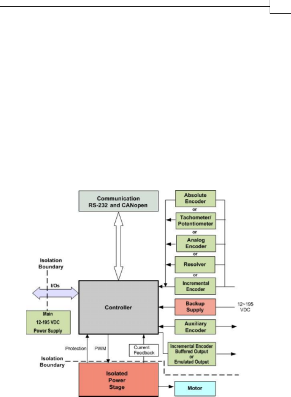
2.3 System Architecture
Figure 2-1: Drum System Block Diagram
Drum Installation Guide Introduction
MAN-DRUIG (Ver. 1.0)
2-4
2.4 How to Use this Guide
In order to install and operate your Elmo Drum servo drives, you will use this manual in
conjunction with a set of Elmo documentation. Installation is your first step; after
carefully reading the safety instructions in the first chapter, the following chapters
provide you with installation instructions as follows:
Chapter 3, Installation, provides step-by-step instructions for unpacking, mounting,
connecting and powering up the Drum.
The Appendix, Technical Specifications, lists all the drive ratings and specifications.
Upon completing the instructions in this guide, your Drum servo drives should be
successfully mounted and installed. From this stage, you need to consult higher-level
Elmo documentation in order to set up and fine-tune the system for optimal operation.
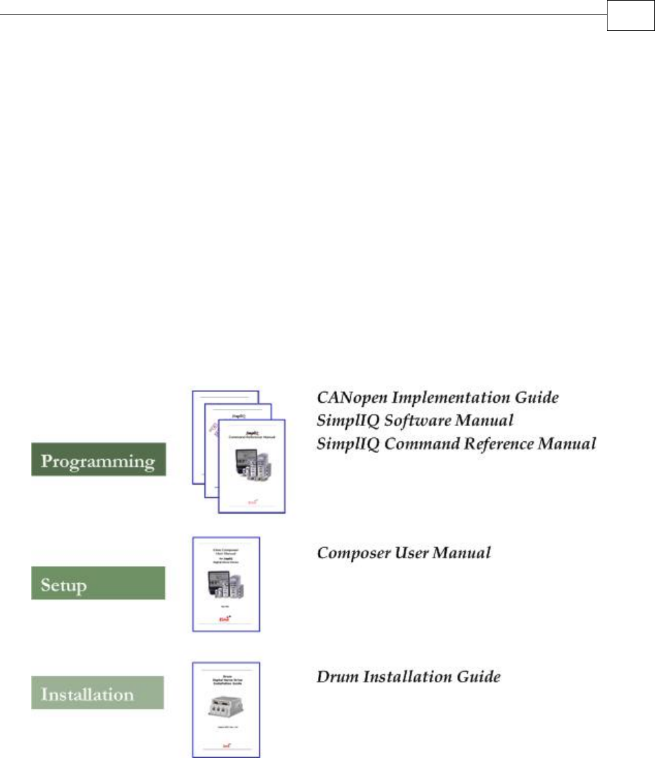
The following figure describes the accompanying documentation that you will require.
Figure 2-2: Elmo Digital Servo Drive Documentation Hierarchy
As depicted in the previous figure, this installation guide is an integral part of the Drum
documentation set, comprising:
The SimplIQ Software Manual, which describes the comprehensive software
used with the Drum.
The SimplIQ Command Reference Manual, which describes, in detail, each
software command used to manipulate the Drum motion controller.
The Composer Software Manual, which includes explanations of all the
software tools that are part of Elmo’s Composer software environment.
Chapter 3: Installation
3.1 Before You Begin
3.1.1 Site Requirements
You can guarantee the safe operation of the Drum by ensuring that it is installed in an
appropriate environment.
Feature Value
Ambient operating temperature 0 °C to 40 °C (32 °F to 104 °F)
Maximum relative humidity 90% non-condensing
Operating area atmosphere No flammable gases or vapors permitted in area
Models for extended environmental conditions are available.
The Drum dissipates its heat by convection. The maximum operating ambient
temperature of 0 °C to 40 °C (32 °F to 104 °F) must not be exceeded.
3.1.2 Hardware Requirements
The components that you will need to install the Drum are:
Component Connector
Described
in Section Diagram
Main Power Cable
VP+ PR 3.4.2.2
Motor Cable M1 M2 M3 3.4.2.1
Drum Installation Guide Installation
3-1
Component Connector
Described
in Section Diagram
Main and Auxiliary
Feedbacks Cable
FEEDBACK A and
FEEDBACK B 3.4.4
Digital I/O and Analog
Input Cable
(if needed)
GENERAL I/O
J1 3.4.7.1
RS232 Communication
Cable
RS232 3.4.8.1
CANopen
Communication cable(s)
(if needed)
CAN (in),
CAN (out) and
Backup Option 3.4.8.2
PC for drive setup and
tuning
Motor data sheet or
manual
Drum Installation Guide Installation
MAN-DRUIG (Ver. 1.0)
3-2
3.2 Unpacking the Drive Components
Before you begin working with the Drum system, verify that you have all of its components,
as follows:
The Drum servo drive
The Composer software and software manual
The Drum is shipped in a cardboard box with styrofoam protection.
To unpack the Drum:
1. Carefully remove the servo drive from the box and the Styrofoam.
2. Check the drive to ensure that there is no visible damage to the instrument. If any damage
has occurred, report it immediately to the carrier that delivered your drive.
3. To ensure that the Drum you have unpacked is the appropriate type for your
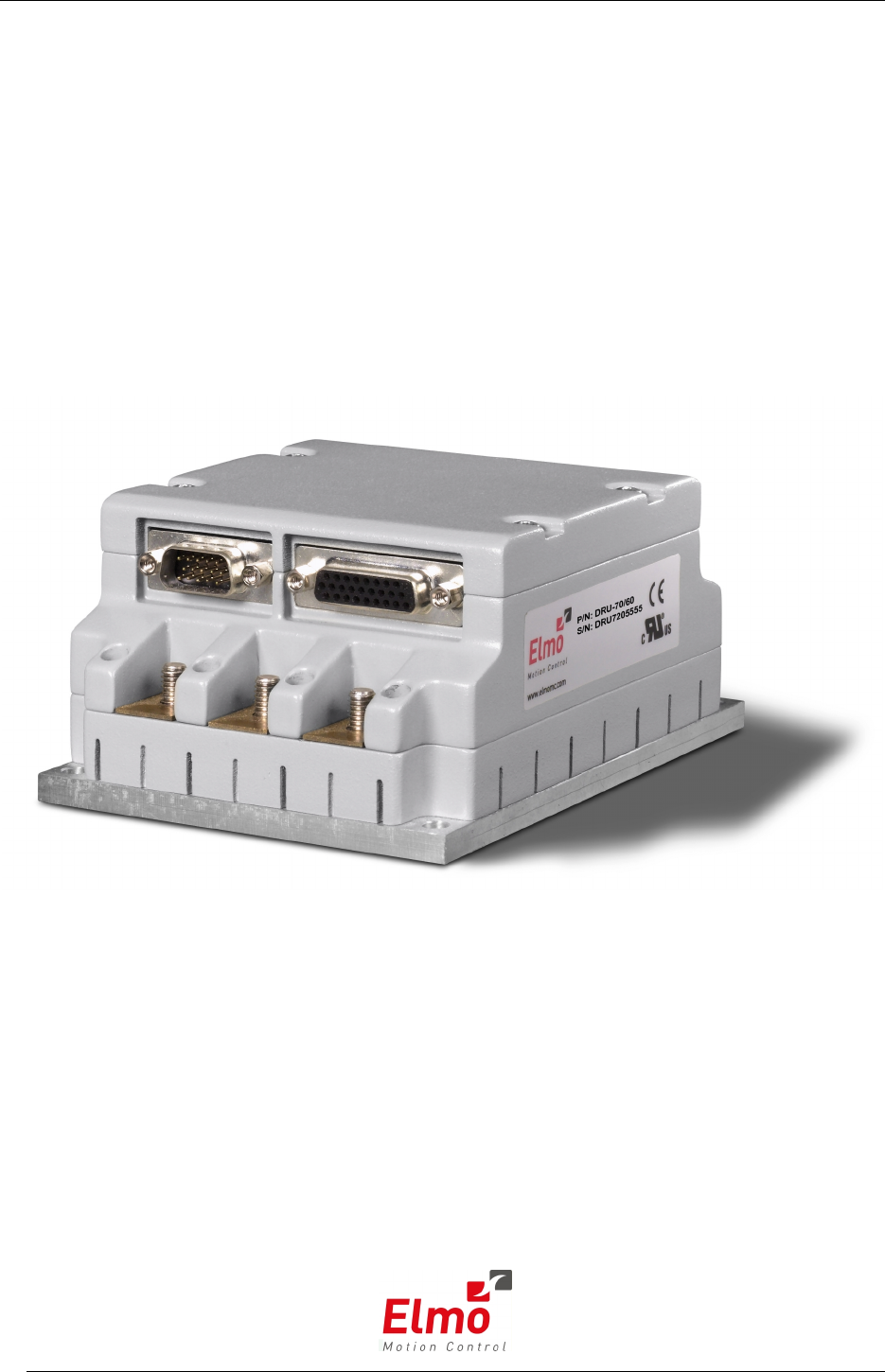
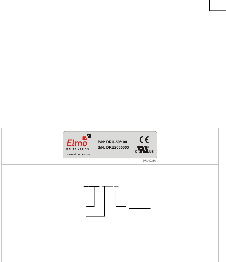
requirements, locate the part number sticker on the side of the Drum. It looks like this:
The P/N number at the top gives the type designation as follows:
Maximum DC
Operating Voltage
Continuous Current
(Amps)
Version :
Blank = Standard
A = Advanced
Feedback:
Blank = Incremental
Encoder
and/or Halls
R=Resolver
DRU- AXX/YYY R
T=Tachometer &
Potentiometer
I = Interpolated
Analog
Encoder
Q= Encoder
Absolute
4. Verify that the Drum type is the one that you ordered, and ensure that the voltage meets
your specific requirements.
Drum Installation Guide Installation
MAN-DRUIG (Ver. 1.0)
3-3
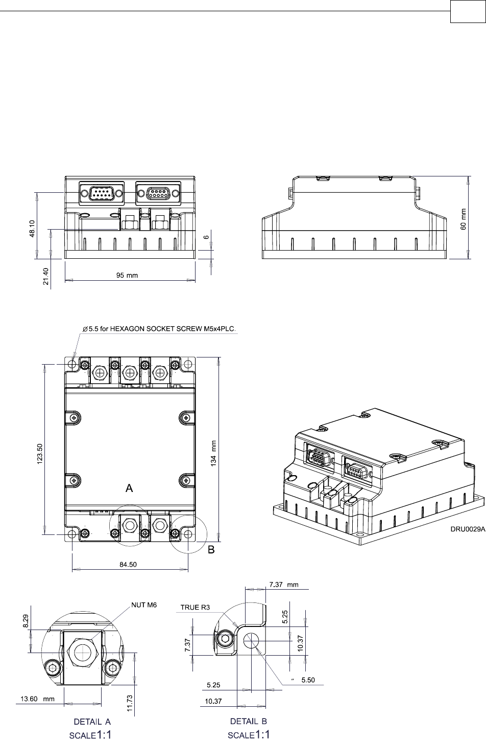
3.3 Mounting the Drum
The Drum has been designed for two standard mounting options:
“Wall Mount” along the back (can also be mounted horizontally on a metal surface)
“Book Shelf” along the side
M5 round head screws, one through each opening in the heat sink, are used to mount the
Drum (see the diagram below).
Figure 3-1: Mounting the Drum
Drum Installation Guide Installation
MAN-DRUIG (Ver. 1.0)
3-4

3.4 Connecting the Cables
3.4.1 Wiring the Drum
Once the Drum is mounted, you are ready to wire the device. Proper wiring, grounding and
shielding are essential for ensuring safe, immune and optimal servo performance of the
Drum.
Follow these instructions to ensure safe and proper wiring:
Use twisted pair shielded cables for control, feedback and communication connections.
For best results, the cable should have an aluminum foil shield covered by copper braid,
and should contain a drain wire.
The drain wire is a non-insulated wire that is in contact with parts of the cable,
usually the shield. It is used to terminate the shield and as a grounding connection.
The impedance of the wire must be as low as possible. The size of the wire must be thicker
than actually required by the carrying current. A 24, 26 or 28 AWG wire for control and
feedback cables is satisfactory although 24 AWG is recommended.
Use shielded wires for motor connections as well. If the wires are long, ensure that the
capacitance between the wires is not too high: C < 30 nF is satisfactory for most
applications.
Keep all wires and cables as short as possible.
Keep the motor wires as far away as possible from the feedback, control and
communication cables.
Ensure that in normal operating conditions, the shielded wires and drain carry no current.
The only time these conductors carry current is under abnormal conditions, when
electrical equipment has become a potential shock or fire hazard while conducting
external EMI interferences directly to ground, in order to prevent them from affecting the
drive. Failing to meet this requirement can result in drive/controller/host failure.
After completing the wiring, carefully inspect all wires to ensure tightness, good solder
joints and general safety.
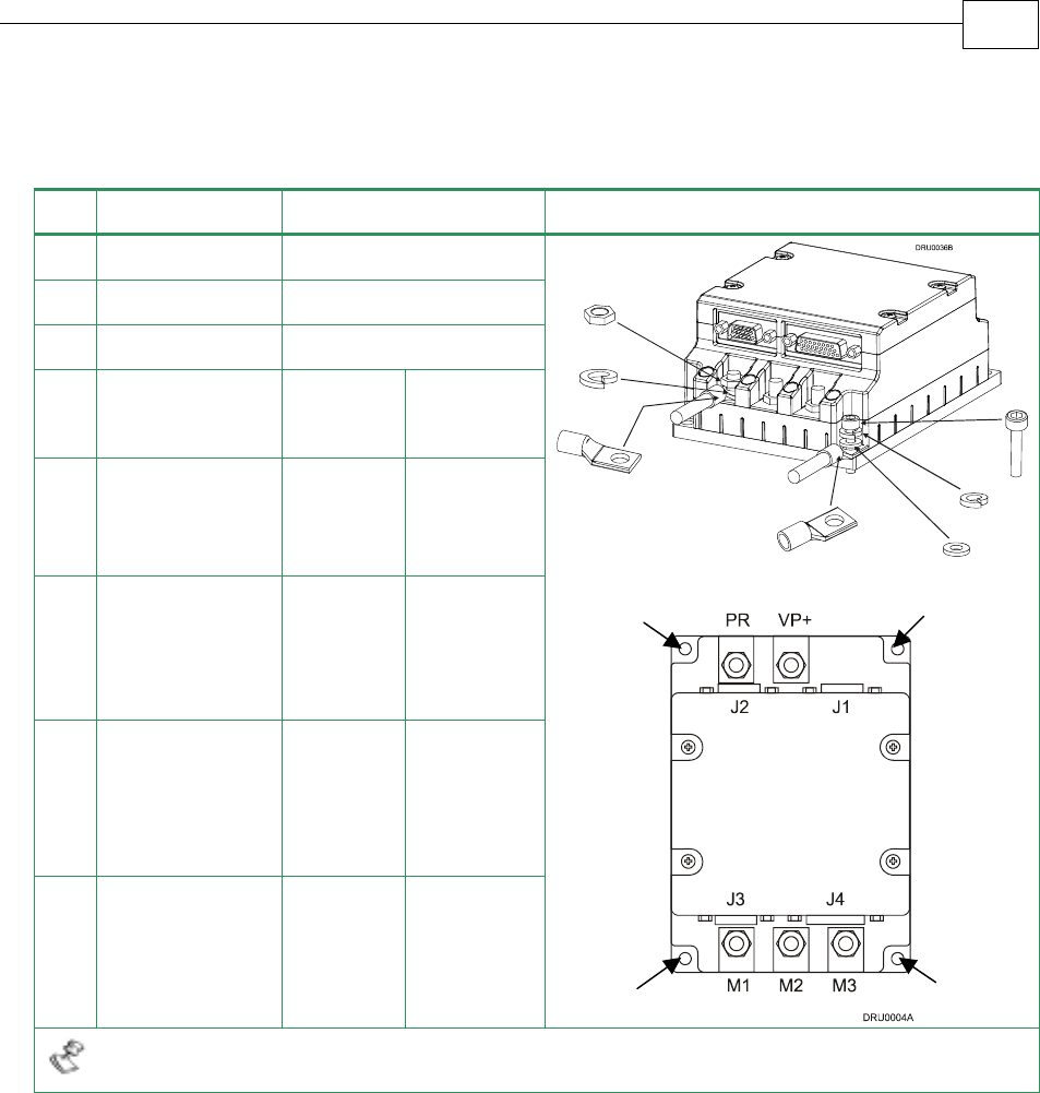
The following connectors are used for wiring the Drum.
Drum Installation Guide Installation
MAN-DRUIG (Ver. 1.0)
3-5
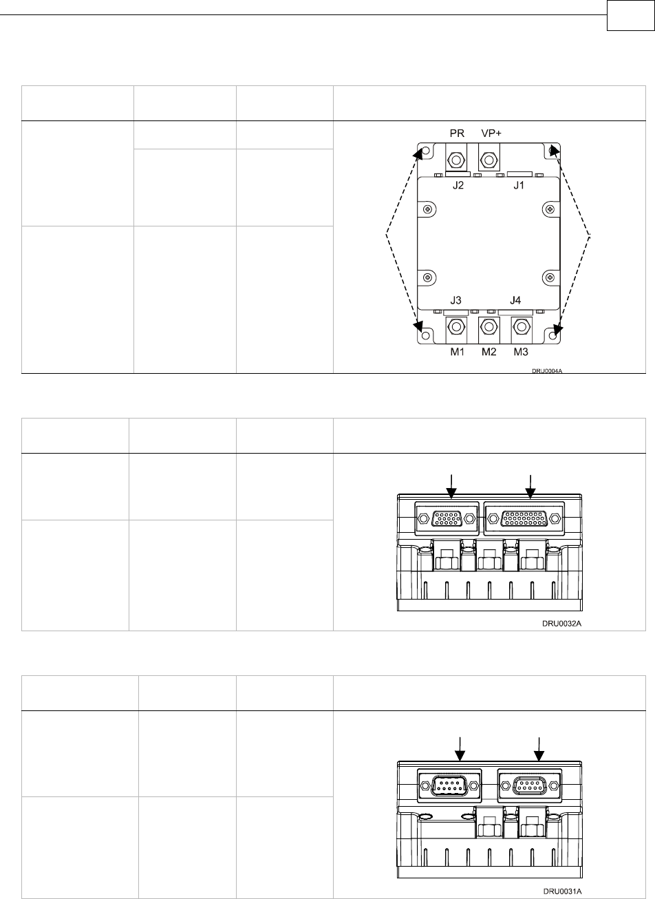
Type Function Port Connector Location
Power VP+, PR Barrel
Connector +
M6 Spring
Washer + M6
Nut
Motor M1, M2, M3
Barrel
Connector +
M5 Flat
Washer + M5
Spring Washer
+ M5 screw
Ground PE, PE, PE,
PE
Table 3-1: Power Connectors on the Drum
Type Function Port Connector Location
26-pin high
density D-
Sub female
Feedbacks A
& B
J4
15-pin high
density D-
Sub male
Analog Input
and General
I/O
J3
Table 3-2: Feedback and I/O Connectors on the Drum
Type Function Port Connector Location
9-pin D-Sub
male
CANopen &
Optional
Backup
Supply
J1
9-pin D-Sub
female
RS-232 J2
Table 3-3: Communication and Backup Connectors on the Drum
J3 Male: I/O J4 Female: Feedbacks A & B
J1 Male: CANopen & Optional
Backup Supply J2 Female: RS-232
PE
PE
Drum Installation Guide Installation
MAN-DRUIG (Ver. 1.0)
3-6
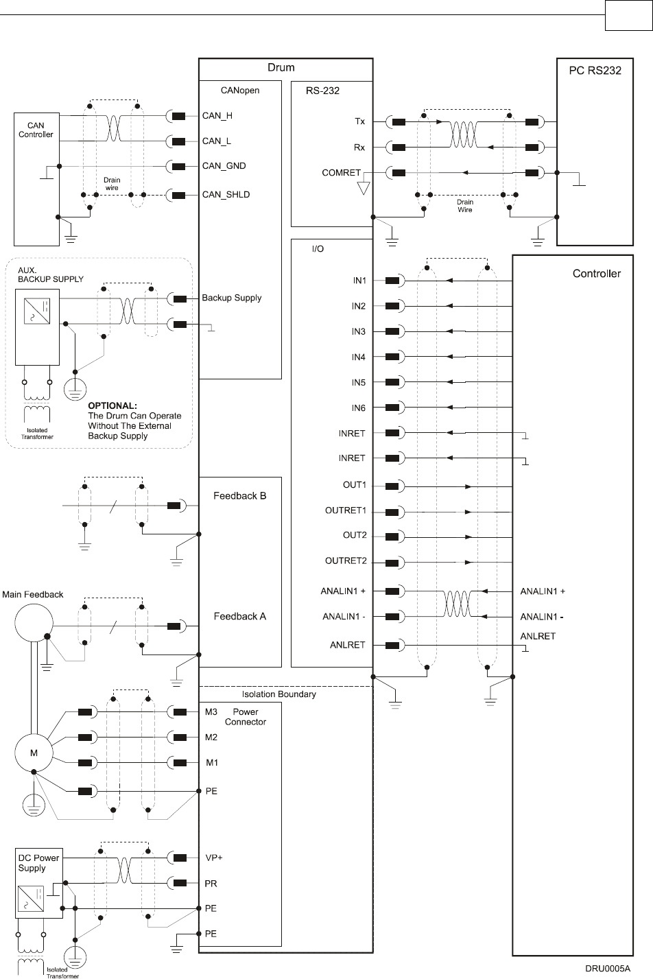
Figure 3-2: Drum Detailed Connection Diagram
Drum Installation Guide Installation
MAN-DRUIG (Ver. 1.0)
3-7
3.4.2 Connecting the Power Cables
The main power connector located at the bottom of the Drum, as follows:
Pin Function Cable Pin Positions
VP+ Pos. Power input Power
PR Power return Power
PE Protective earth Power
3-Phase
Motor
Cable
DC Motor
Cable
PE Protective earth Motor Motor
M1 Motor phase Motor N/C
M2 Motor phase Motor Motor
M3 Motor phase Motor Motor
When connecting several motors, all must be wired in an identical manner.
Table 3-4: Connector for Main Power and Motor Cables
PE
PE
PE
PE
Drum Installation Guide Installation
MAN-DRUIG (Ver. 1.0)
3-8
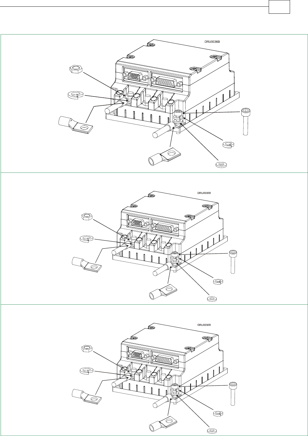
Step 1: PE Connection
Step 2: Power and Motor Connection
Table 3-5: Connecting the Main Power and Motor Cables
M5
screw
M5 spring washer
M5 flat washer
M6 nut (available
with the drive
)
M6 spring
washer
barrel
connector
M5 screw
M5 sprin
g
washer
M6 nut (available
with the drive
)
M5 flat washer
barrel connector
barrel connector
M6 spring washer
barrel
connector
Drum Installation Guide Installation
MAN-DRUIG (Ver. 1.0)
3-9
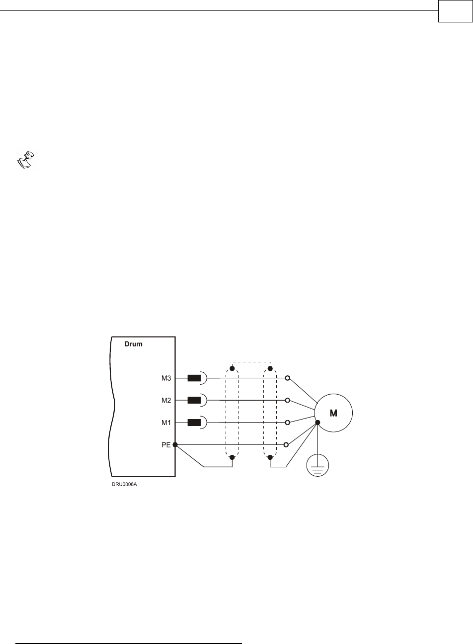
3.4.2.1 Connecting the Motor Cable
Connect the motor power cable to the M1, M2, and M3 terminals of the main power connector
and the fourth wire to the PE (Protective Earth) on the heat sink (see diagram above). The
phase connection order is arbitrary because the Composer will establish the proper
commutation automatically during setup.
Notes for connecting the motor cables:
For best immunity, it is highly recommended to use a shielded (not twisted) cable for
the motor connection. A 4-wire shielded cable should be used. The gauge is
determined by the actual current consumption of the motor.
Connect the shield of the cable to the closest ground connection at the motor end.
Connect the shield of the cable to the PE terminal on the Drum.
Be sure that the motor chassis is properly grounded.
To close the motor cable into the drive, use the barrel connector, M6 spring washer
and M6 nut (in the drive). The required torque is 3-4 Nm.
To close the PE wire into the drive, use the barrel connector, M5 flat washer, M5
spring washer and M5 screw to the heatsink. The required torque is 3-4 Nm.
Figure 3-3: AC Motor Power Connection Diagram
3.4.2.2 Connecting the DC Power
The Power stage of the Drum is fully isolated from other sections of the Drum, such as the
control stage and the heatsink. This contributes very significantly to the safety and the EMI
immunity of the Drum. In addition it simplifies the requirements of the DC power supply
used to power the DC bus of the Drum and allows also the operation with a non-isolated DC
power source.
Operation with an Isolated DC power Supply:
The PE (Protective Ground of the AC network) is connected to the PR terminal [The negative
power terminal (-)].
Drum Installation Guide Installation
MAN-DRUIG (Ver. 1.0)
3-10
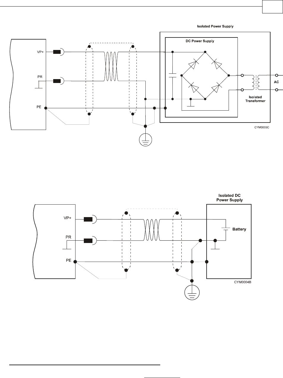
Figure 3-4: Isolated DC Power Supply
In this case the isolation is achieved by the isolation transformer.
It is highly recommended to connect the network PE to the Return (negative terminal) of the
Power Supply.
Figure 3-5: Isolated Power Supply
In this case the isolation is achieved by using a battery.
It is highly recommended to connect the PE to the Return (negative terminal) of the Power
Supply.
Operation with a NON- Isolated DC power Supply:
The PE (Protective Ground of the AC network) MUST NOT be connected to the Return [PR
terminal, the negative power terminal (-)] of the Drum.
Drum
Drum
Drum Installation Guide Installation
MAN-DRUIG (Ver. 1.0)
3-11
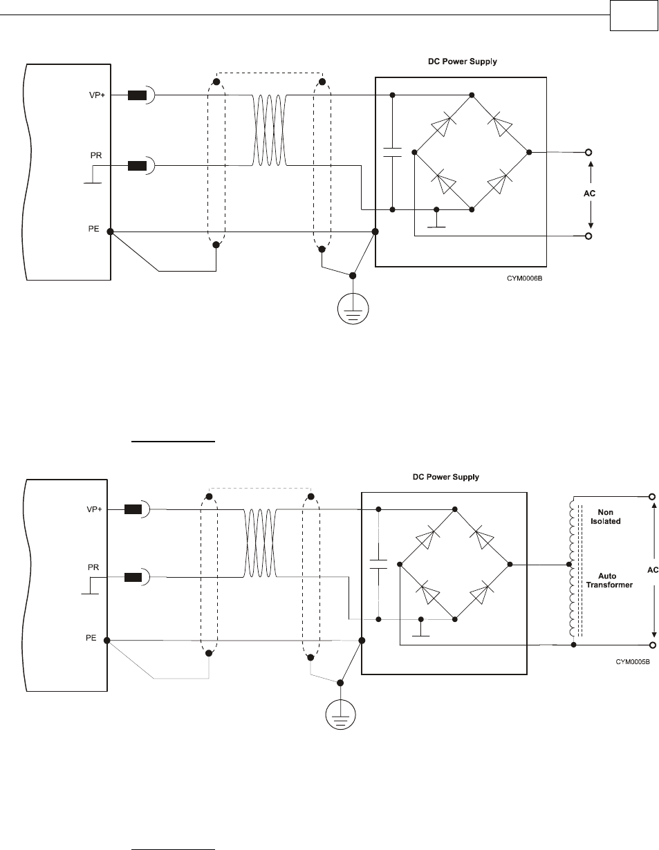
Figure 3-6: Non-Isolated DC Power Supply
The Power Supply is directly connected to the AC line (The AC must be limited to 135 VAC
not to exceed the max 190 VDC in case of 200 VDC drive).
The network PE MUST NOT be connected to the Return of the Power Supply.
Figure 3-7: Non-Isolated DC Power Supply
The Power Supply is directly connected to the AC line through an Autotransformer.
The network PE MUST NOT be connected to the Return of the Power Supply.
Warning: Connecting the PE to the PR with a non- isolated power supply will cause damages
to the system (Any component that is connected to the system might be damaged).
Drum
Drum
Drum Installation Guide Installation
MAN-DRUIG (Ver. 1.0)
3-12

Notes for connecting the DC power supply:
Be aware: The Drum can operate from either an:
oisolated DC power supply
or
onon-isolated DC power supply
For best immunity, it is highly recommended to use twisted cables for the DC power
supply cable. A 3-wire shielded cable should be used. The gauge is determined by
the actual current consumption of the motor.
Connect both ends of the cable shield to the closest ground connection, one end near
the power supply and the other end to the PE terminal on the Drum’s heatsink.
For safety reasons connect the PR of the power supply to the closest ground
connection.
To close the power supply cable into the drive, use the barrel connector, M6 spring
washer and M6 nut (in the drive). The required torque is 3-4 Nm.
To close the PE wire into the drive, use the barrel connector, M5 flat washer, M5
spring washer and M5 screw to the heatsink. The required torque is 3-4 Nm.
3.4.2.3 Connecting the Optional Back-up Supply Cable
Power to the Drum is provided by a 12 to 195 VDC source (depending on model type). A
“smart” control-supply algorithm enables the Drum to operate with the power supply only,
with no need for an auxiliary supply voltage. If backup functionality is required for storing
control parameters in case of power-outs, an external 12-195 VDC power supply can be
connected, providing maximum flexibility and optional backup functionality when needed.
To connect the back-up supply to the Auxiliary port, use the Drum's J1 connector (CAN
communication connector). Remember, you are working with DC power so be sure to exercise
caution.
Notes for back-up supply connections:
Use a 24 AWG twisted pair shielded cable. The shield should have copper braid.
The source of the back-up supply must be isolated.
For safety reasons, connect the return of the back-up supply source to the closest
ground.
Connect the cable shield to the closest ground near the power source.
Before applying power, first verify the polarity of the connection.
Drum Installation Guide Installation
MAN-DRUIG (Ver. 1.0)
3-13
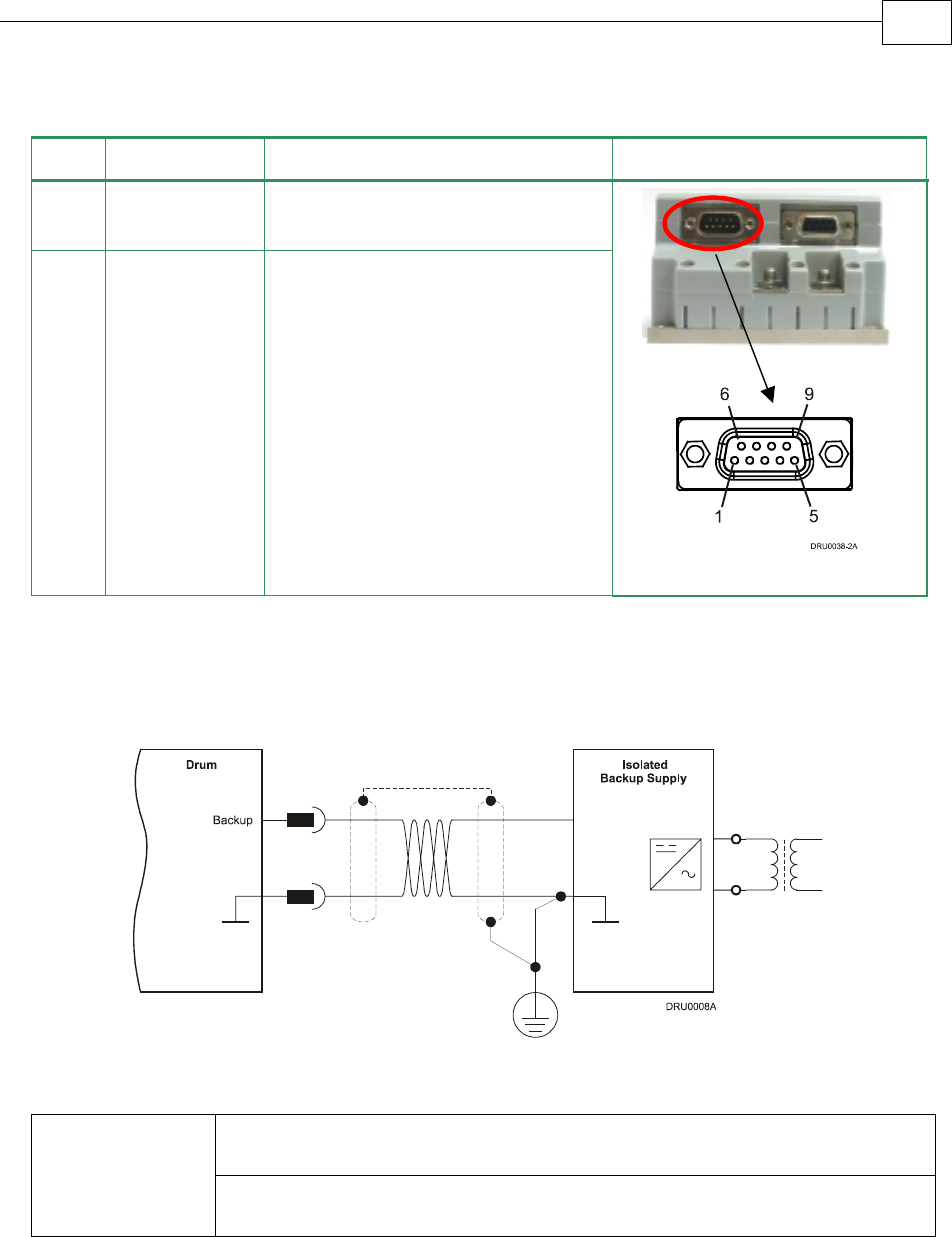
Pin Signal Function Pin Position
J1-9 +VDC Backup
Supply
+VDC back-up supply
J1-8 RET Backup
Supply
Return (common) of the back-up
supply
Table 3-6: Back-up Cable Plug
Figure 3-8: Back-up Supply Connection Diagram
Internal DC-to-DC converter allowing for operation from DC power (no
need for auxiliary external supply for normal operation).
“Smart” Control
Supply Options
12-195 VDC supply for backing up the control parameters if DC power is
shut off.
3.4.3 Feedback Control and Communication Cable
Assemblies
The Drum features easy-to-use D-sub type connections for all Control and Feedback cables.
Below are instructions and diagrams describing how to assemble those cables.
Use 24, 26 or 28 AWG twisted-pair shielded cables (24 AWG cable is recommended).
For best results, the shield should have aluminum foil covered by copper braid.
J1
Male
Drum Installation Guide Installation
MAN-DRUIG (Ver. 1.0)
3-14
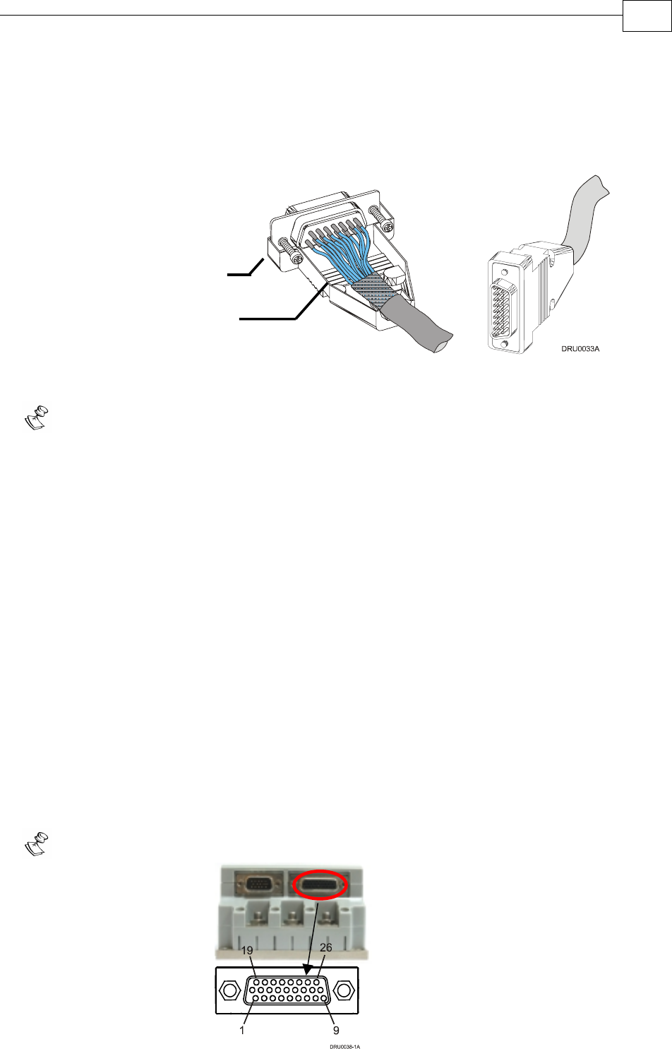
Use only a D-sub connector with a metal housing.
Attach the braid shield tightly to the metal housing of the D-type connector.
On the motor side connections, ground the shield to the motor chassis.
On controller side connections, follow the controller manufacturer’s
recommendations concerning the shield.
Figure 3-9: Feedback and Control Cable Assemblies
Note: All D-sub type connectors, used with the Drum, should be assembled in this way.
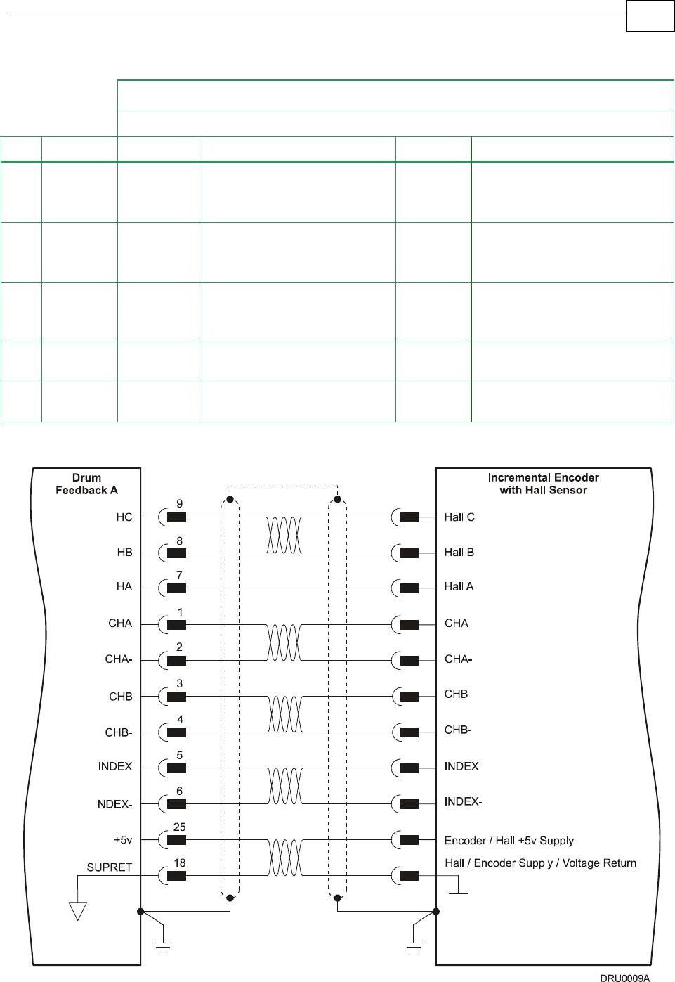
3.4.4 Main Feedback Cable (FEEDBACK A)
The main feedback cable is used to transfer feedback data from the motor to the drive.
The Drum accepts the following as a main feedback mechanism:
Incremental encoder only
Incremental encoder with digital Hall sensors
Digital Hall sensors only
Incremental Analog (Sine/Cosine) encoder (option)
Resolver (option)
Tachometer & Potentiometer
Absolute Encoder
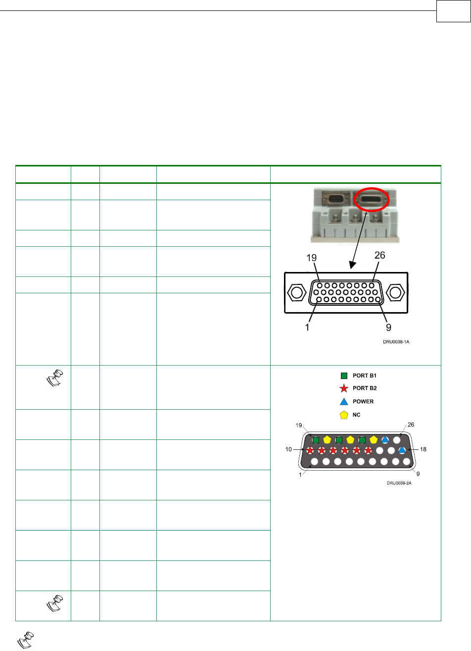
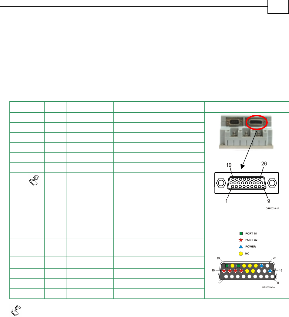
FEEDBACK A on the “front” of the Drum has a 26-pin high density D-sub socket. Connect the
Main Feedback cable from the motor to FEEDBACK A using a 26-pin, high density D-Sub
plug with a metal housing. When assembling the Main Feedback cable, follow the instructions
in Section 3.4.3 (Feedback Control and Communication Cable Assemblies).
Note: the Feedback connector also supports Feedbacks A and B.
Metal Housing
Make sure that the braid shield is in
tight contact with the metal housing
J4 Female
Drum Installation Guide Installation
MAN-DRUIG (Ver. 1.0)
3-15

Incremental Encoder
Interpolated Analog
Encoder
Resolver Tachometer and
Potentiometer
DRU XX/YYY_ DRU XX/YYYI DRU XX/YYYR DRU XX/YYYT
Pin Port Signal Function Signal Function Signal Function Signal Function
1 A–
Main
Input
CHA Channel A A+ Sine A S1 Sine A Tac1+ Tacho
Input 1
Pos. (20 V
max)
2 A–
Main
Input
CHA- Channel A
Complement
A- Sine A
Complement
S3 Sine A
Complement
Tac1- Tacho
Input 1
Neg.
(20 V
max)
3 A–
Main
Input
CHB Channel B B+ Cosine B S2 Cosine B Tac2+ Tacho
Input 2
Pos. (50 V
max)
4 A–
Main
Input
CHB- Channel B
Complement
B- Cosine B
Complement
S4 Cosine B
Complement
Tac2- Tacho
Input 2
Neg.
(50 V
max)
5 A–
Main
Input
INDEX Index R+ Reference R1 Vref f=1/TS,
50mA Max.
POT Potentio-
meter
Input
6 A–
Main
Input
INDEX- Index
Complement
R- Reference
Complement
R2 Vref
complement
f= 1/TS,
50 mA Max.
NC -
7 Hall A HA Hall sensor
A input
HA Hall sensor A
input
HA Hall sensor A
input
HA Hall
sensor A
input
8 Hall B HB Hall sensor B
input
HB Hall sensor B
input
HB Hall sensor B
input
HB Hall
sensor B
input
9 Hall C HC Hall sensor
C input
HC Hall sensor C
input
HC Hall sensor C
input
HC Hall
sensor C
input
10 B2 –
Aux.
Output
CHAO Aux./Main
channel A
high output
CHAO Aux./
Emulated
channel A
high output
CHAO Aux./
Emulated
channel A
high output
CHAO Aux./
Emulated
channel A
high
output
11 B2 –
Aux.
Output
CHAO- Aux./Main
channel A
low output
CHAO- Aux./
Emulated
channel A
low output
CHAO- Aux./
Emulated
channel A
low output
CHAO- Aux./
Emulated
channel A
low
output
12 B2 –
Aux.
Output
CHBO Aux./Main
channel B
high output
CHBO Aux./
Emulated
channel B
high output
CHBO Aux./
Emulated
channel B
high output
CHBO Aux./
Emulated
channel B
high
output
Drum Installation Guide Installation
MAN-DRUIG (Ver. 1.0)
3-16

Incremental Encoder
Interpolated Analog
Encoder
Resolver Tachometer and
Potentiometer
DRU XX/YYY_ DRU XX/YYYI DRU XX/YYYR DRU XX/YYYT
Pin Port Signal Function Signal Function Signal Function Signal Function
13 B2 – Aux.
Output
CHBO- Aux./Main
channel B low
output
CHBO- Aux./
Emulated
channel B low
output
CHBO- Aux./
Emulated
channel B low
output
CHBO- Aux./
Emulated
channel B
low output
14 B2 – Aux.
Output
INDEXO Aux./Main
INDEX high
output
INDEXO Aux. INDEX
high output
INDEXO Aux./
Emulated
INDEX high
output
INDEXO Aux.
INDEX
high
output
15 B2 – Aux.
Output
INDEXO- Aux./Main
INDEX low
output
INDEXO- Aux. INDEX
low output
INDEXO
-
Aux./
Emulated
INDEX low
output
INDEXO- Aux.
INDEX
low output
16 PWR SUPRET Supply return SUPRET Supply return SUPRET Supply return SUPRET Supply
return
17 PWR SUPRET Supply return SUPRET Supply return SUPRET Supply return SUPRET Supply
return
18 PWR SUPRET Supply return SUPRET Supply return SUPRET Supply return SUPRET Supply
return
19 B1 – Aux.
Input/
Output
CHA Main channel A
high output/
Auxiliary
channel A high
input
CHA Emulated
channel A
high output/
Auxiliary
channel A
high input
CHA Emulated
channel A high
output/
Auxiliary
channel A high
input
CHA Emulated
channel A
high
output/
Auxiliary
channel A
high input
20 B1 – Aux.
Input/
Output
CHA- Main channel A
low output/
Auxiliary
channel A low
input
CHA- Emulated
channel A low
output/
Auxiliary
channel A low
input
CHA- Emulated
channel A low
output/
Auxiliary
channel A low
input
CHA- Emulated
channel A
low
output/
Auxiliary
channel A
low input
21 B1 – Aux.
Input/
Output
CHB Main channel B
high output/
Auxiliary
channel B high
input
CHB Emulated
channel B
high output/
Auxiliary
channel B
high input
CHB Emulated
channel B high
output/
Auxiliary
channel B high
input
CHB Emulated
channel B
high
output/
Auxiliary
channel B
high input
Drum Installation Guide Installation
MAN-DRUIG (Ver. 1.0)
3-17

Incremental Encoder
Interpolated Analog
Encoder
Resolver Tachometer and
Potentiometer
DRU XX/YYY_ DRU XX/YYYI DRU XX/YYYR DRU XX/YYYT
Pin Port Signal Function Signal Function Signal Function Signal Function
22 B1 – Aux.
Input/
Output
CHB- Main channel
B low output/
Auxiliary
channel B low
input
CHB- Emulated
channel B low
output/
Auxiliary
channel B low
input
CHB- Emulated
channel B low
output/
Auxiliary
channel B low
input
CHB- Emulated
channel B
low
output/
Auxiliary
channel B
low input
23 B1 – Aux.
Input/
Output
INDEX Main INDEX
high output/
Auxiliary
INDEX high
input
INDEX Auxiliary
INDEX high
input
INDEX Emulated
INDEX high
output/
Auxiliary
INDEX high
input
INDEX Auxiliary
INDEX
high input
24 B1 – Aux.
Input/
Output
INDEX- Main INDEX
low output/
Auxiliary
INDEX low
input
INDEX- Auxiliary
INDEX low
input
INDEX- Emulated
INDEX low
output/
Auxiliary
INDEX low
input
INDEX- Auxiliary
INDEX
low input
25 PWR +5V Encoder/
Hall +5V
supply
+5V Encoder/Hall
+5V supply
+5V Encoder/
Hall +5V supply
+5V Encoder/
Hall +5V
supply
26 PWR +5V
Encoder/
Hall +5V
supply
+5V Encoder/Hall
+5V supply
+5V Encoder/
Hall +5V supply
+5V Encoder/
Hall +5V
supply
Table 3-7: Feedback Cable Pin Assignments
Drum Installation Guide Installation
MAN-DRUIG (Ver. 1.0)
3-18

Absolute Encoders
DRU XX/YYY
Pin Port Signal Heidenhain 2.1 Signal Stegmann
1 A– Main
Input
A+ Sine A A- Sine A Complement
2 A– Main
Input
A- Sine A Complement A+ Sine A
3 A– Main
Input
B+ Cosine B B+ Cosine B
4 A– Main
Input
B- Cosine B Complement B- Cosine B Complement
5 A– Main
Input
DATA+ Data DATA+ Data
6 A– Main
Input
DATA- Data Complement DATA- Data Complement
7 Hall A HA Hall sensor A
input
HA Hall sensor A
input
8 Hall B HB Hall sensor B
input
HB Hall sensor B
input
9 Hall C HC Hall sensor C
input
HC Hall sensor C
input
10 B2– Aux.
Output
CHAO Aux. / Emulated channel A high
output
CHAO Aux. channel A high output
/ Emulated channel A low output
11 B2– Aux.
Output
CHAO- Aux. / Emulated channel A low
output
CHAO- Aux. channel A low output /
Emulated channel A high output
12 B2– Aux.
Output
CHBO Aux. / Emulated channel B high
output
CHBO Aux. / Emulated channel B high
output
13 B2– Aux.
Output
CHBO- Aux. / Emulated channel B low
output
CHBO- Aux. / Emulated channel B low
output
14 B2– Aux.
Output
INDEXO Aux. INDEX high output INDEXO Aux. INDEX high output
15 B2– Aux.
Output
INDEXO- Aux. INDEX low output INDEXO- Aux. INDEX low output
16 CLK+ Clock N.A Do not connect
17 CLK- Clock Complement N.A Do not connect
18 PWR SUPRET Supply return SUPRET Supply return
19 B1– Aux.
Input/
Output
CHA Emulated channel A high
output/Auxiliary channel A
high input
CHA Emulated channel A low output /
Auxiliary channel A high input
20 B1– Aux.
Input/
Output
CHA- Emulated channel A low
output/Auxiliary channel A low
input
CHA- Emulated channel A high output /
Auxiliary channel A low input
21 B1– Aux.
Input/
Output
CHB Emulated channel B high
output/Auxiliary channel B high
input
CHB Emulated channel B high output/
Auxiliary channel B high input
Drum Installation Guide Installation
MAN-DRUIG (Ver. 1.0)
3-19
Absolute Encoders
DRU XX/YYY
Pin Port Signal Heidenhain 2.1 Signal Stegmann
22 B1– Aux.
Input/
Output
CHB- Emulated channel B low output/
Auxiliary channel B low input
CHB- Emulated channel B low output/
Auxiliary channel B low input
23 B1– Aux.
Input/
Output
INDEX Auxiliary INDEX high input INDEX Auxiliary INDEX high input
24 B1– Aux.
Input/
Output
INDEX- Auxiliary INDEX low input INDEX- Auxiliary INDEX low input
25 PWR +5V Encoder/Hall +5V supply +5V +5V Hall
supply
26 PWR +8V Do not connect +8V +8V Encoder
supply
Table 3-7B: Feedback Cable Pin Assignments
Figure 3-10: Main Feedback- Incremental Encoder Connection Diagram
Drum Installation Guide Installation
MAN-DRUIG (Ver. 1.0)
3-20
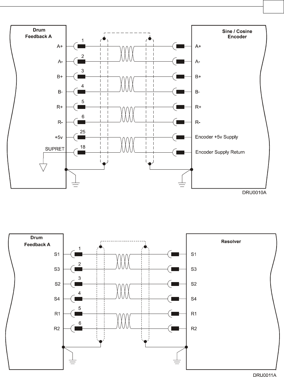
Figure 3-11: Main Feedback – Interpolated Analog Encoder Connection Diagram
Figure 3-12: Main Feedback – Resolver Connection Diagram
Drum Installation Guide Installation
MAN-DRUIG (Ver. 1.0)
3-21
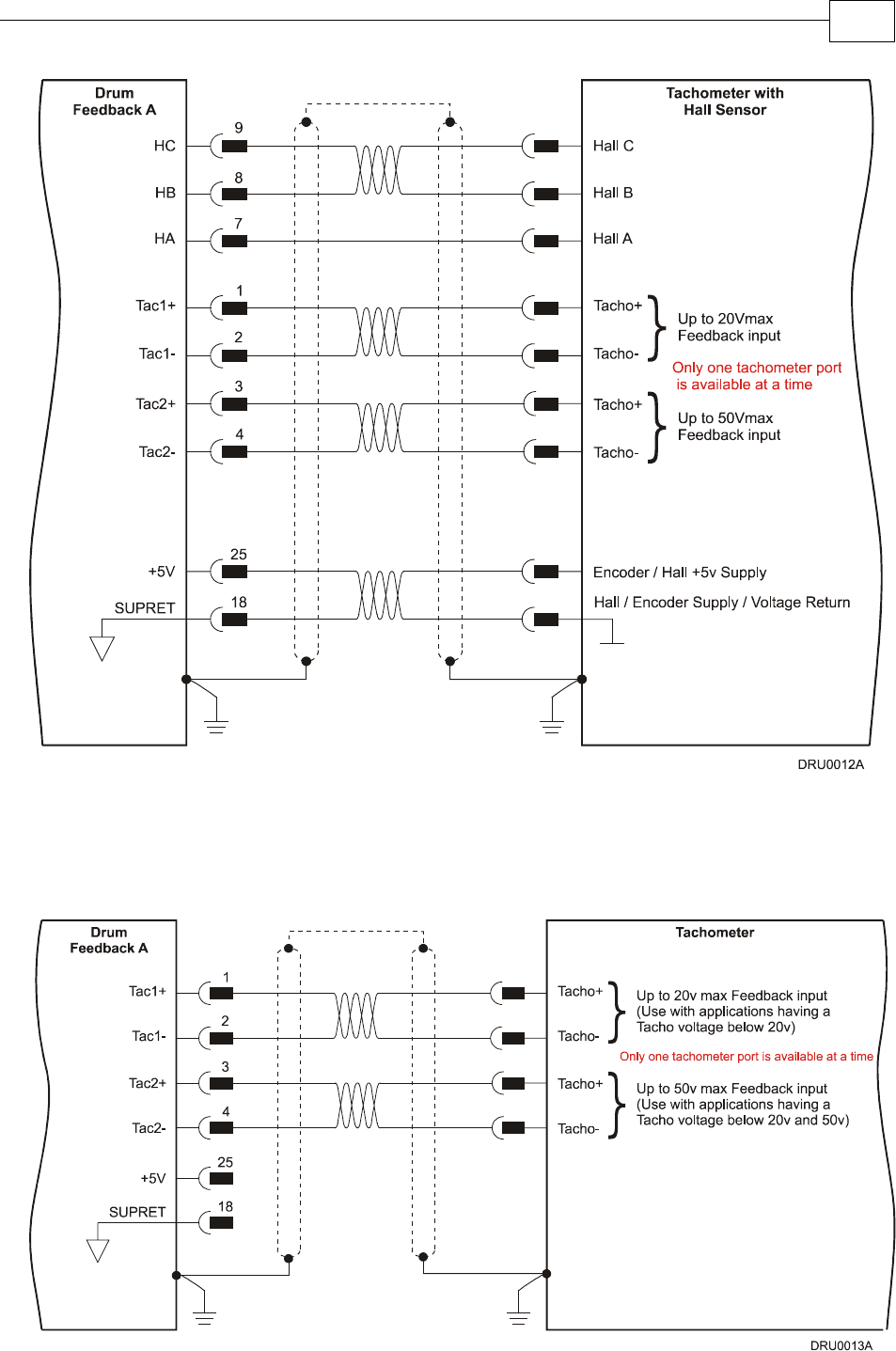
Figure 3-13: Main Feedback – Tachometer Feedback with Digital Hall Sensor
Connection Diagram for Brushless Motors
Figure 3-14: Main Feedback – Tachometer Feedback Connection Diagram for Brush Motors
Drum Installation Guide Installation
MAN-DRUIG (Ver. 1.0)
3-22
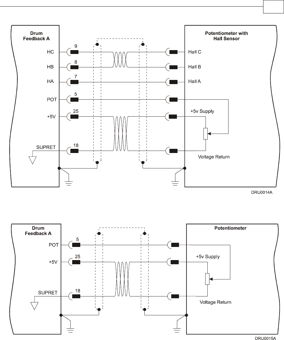
Figure 3-15: Main Feedback – Potentiometer Feedback with Digital Hall Sensor
Connection Diagram for Brushless Motors
Figure 3-16: Main Feedback –
Potentiometer Feedback Connection Diagram for Brush Motors and Voice Coils
Drum Installation Guide Installation
MAN-DRUIG (Ver. 1.0)
3-23
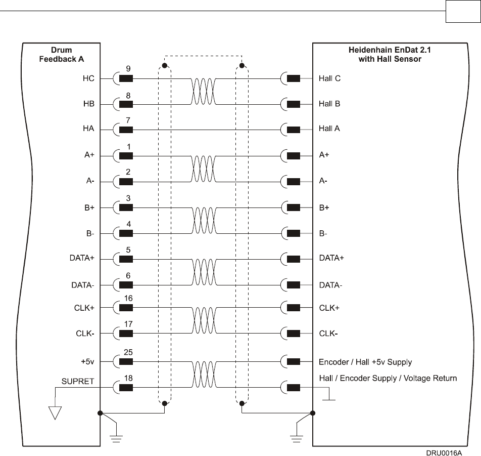
Figure 3-17: Main Feedback – Heidenhain (EnDat 2.1) Feedback with Hall Sensor
Connection Diagram
Drum Installation Guide Installation
MAN-DRUIG (Ver. 1.0)
3-24
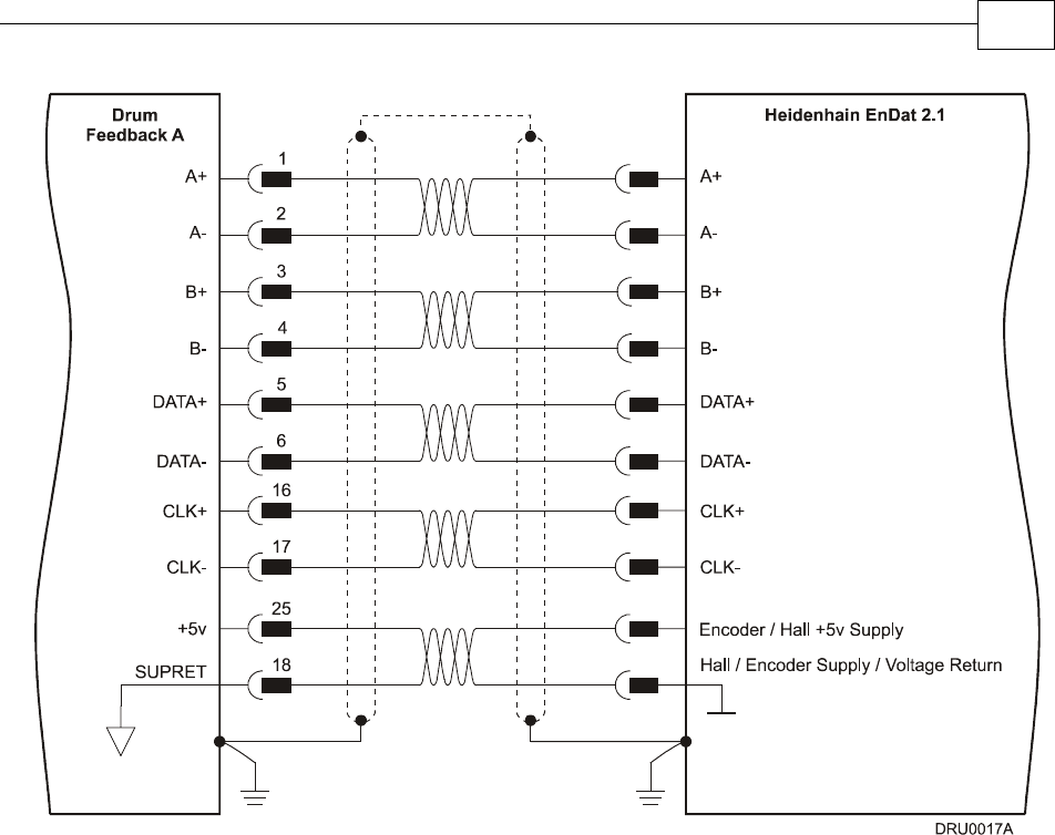
Figure 3-18: Main Feedback – Heidenhain (EnDat 2.1) Feedback Connection Diagram
Drum Installation Guide Installation
MAN-DRUIG (Ver. 1.0)
3-25
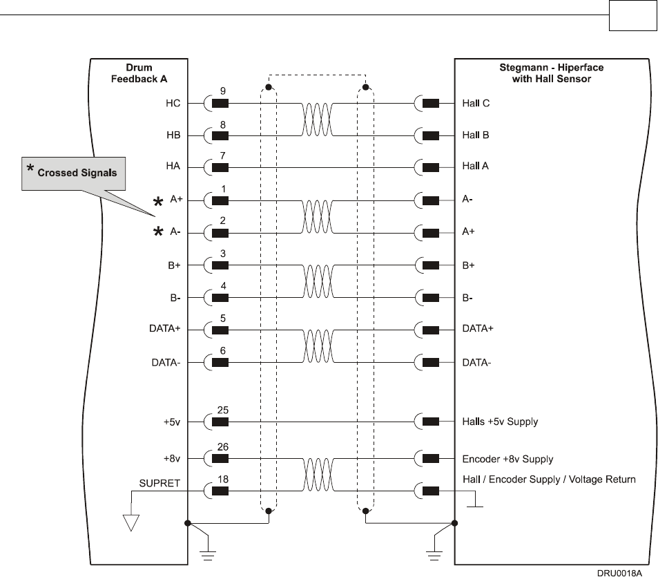
Figure 3-19: Main Feedback – Stegmann (Hiperface) Feedback with Hall Sensor
Connection Diagram
Drum Installation Guide Installation
MAN-DRUIG (Ver. 1.0)
3-26
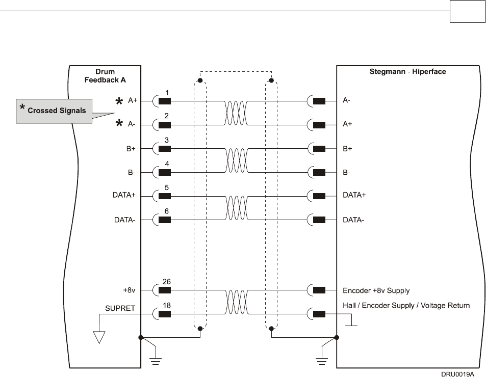
Figure 3-20: Main Feedback – Stegmann (Hiperface) Feedback Connection Diagram
Drum Installation Guide Installation
MAN-DRUIG (Ver. 1.0)
3-27
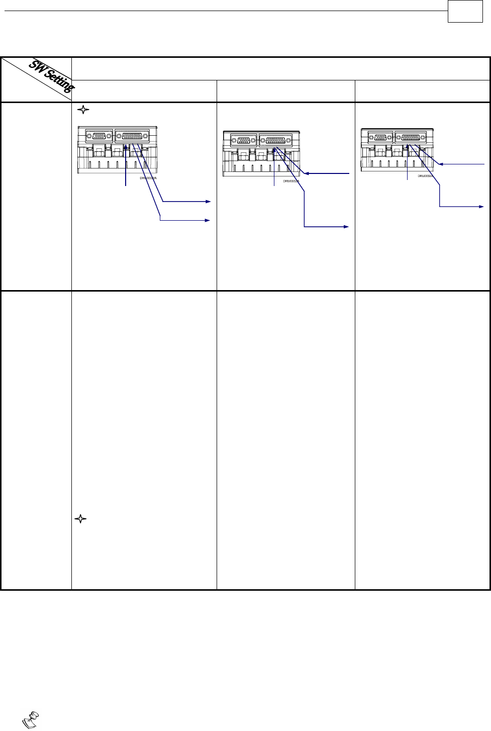
3.4.5 Main and Auxiliary Feedback Combinations
The Main Feedback is always used in motion control devices whereas Auxiliary Feedback is
often, but not always used. The Auxiliary Feedback connector on the Drum, “FEEDBACK B”
has two ports, Port B1 and Port B2. When used in combination with the Main Feedback port,
“FEEDBACK A”, the ports can be set, by software, as follows:
FEEDBACK B Ports B1 and B2
FEED-
BACK A YA[4] = 4 YA[4] = 2 YA[4] = 0
Incremental
Encoder
Input
B1 - Output
B2 - output
same as B1
Differential
and
Buffered
Main
Encoder
Signal
Incremental
Encoder
A - input
Interpolated
Analog
(Sin/Cos)
Encoder
Input
A-input
Analog
Encoder
Analog
Encoder
Position
Data
Emulated in
Incremental
Encoder
Format
(signals are
quadrature,
differential
& buffered)
B1- Output
B2- Output
same as B1
Resolver
Input
A-input
Resolver
Resolver
Position
Data
Emulated in
Incremental
Encoder
Format
(signals are
quadrature,
differential
& buffered)
same as B1
B1- Output
B2- Output
Tachometer
Input A-input
Tachometer
Tachometer
Position
Data
Emulated in
Incremental
Encoder
Format
(signals are
quadrature,
differential
& buffered)
B1- Output
B2- Output
same as B1
Differential
or
Single-ended
Auxiliary
Incremental
Encoder
B1- Input
B2- Output
Differential
and
Buffered
Auxiliary
Encoder
Signal
Incremental
Encoder
or
Analog
Encoder
or
Resolver
or
Tachometer
or
Potentiometer
or
Absolute
Encoder
Differential or
Single-ended
Pulse &
Direction
Commands
Differential
and Buffered
Pulse &
Direction
Signals
B1- Input
B2- Output
Incremental
Encoder
or
Analog
Encoder
or
Resolver
or
Tachometer
or
Potentiometer
or
Absolute
Encoder
*
Drum Installation Guide Installation
MAN-DRUIG (Ver. 1.0)
3-28
FEEDBACK B Ports B1 and B2
FEED-
BACK A YA[4] = 4 YA[4] = 2 YA[4] = 0
P
otentiometer
Input
A-input
Potentiometer
Potentiometer
Position Data
Emulated in
Incremental
Encoder
Format
(signals are
quadrature,
differential &
buffered)
B1- Output
B2- Output
same as B1
Differential
or
Single-ended
Auxiliary
Incremental
Encoder
B1- Input
B2- Output
Differential
and
Buffered
Auxiliary
Encoder
Signal
Incremental
Encoder
or
Analog
Encoder
or
Resolver
or
Tachometer
or
Potentiometer
or
Absolute
Encoder
Differential or
Single-ended
Pulse &
Direction
Commands
Differential
and Buffered
Pulse &
Direction
Signals
B1- Input
B2- Output
Incremental
Encoder
or
Analog
Encoder
or
Resolver
or
Tachometer
or
Potentiometer
or
Absolute
Encoder
Typical
Applications Any application where the
main encoder is used, not
only for the drive, but also
for other purposes such as
position controllers and/or
other drives.
Analog Encoder
applications where position
data is required in the
Encoder’s quadrature
format.
Resolver applications
where position data is
required in the Encoder’s
quadrature format.
Tachometer applications
where velocity data is
required in the Encoder’s
quadrature format.
Absolute Encoder
applications where position
data is required in the
Encoder’s quadrature
format.
Any application where two
feedbacks are used by the
drive.
Port B1 serves as an input for
the auxiliary incremental
encoder (differential or
single-ended).
Port B2 is used to output
differential buffered
Auxiliary Incremental
Encoder signals.
For applications such as
Follower, ECAM, or Dual
Loop.
Port B1 serves as an input for
Pulse & Direction
commands (differential or
single-ended).
Port B2 is used to output
differential buffered Pulse &
Direction signals.
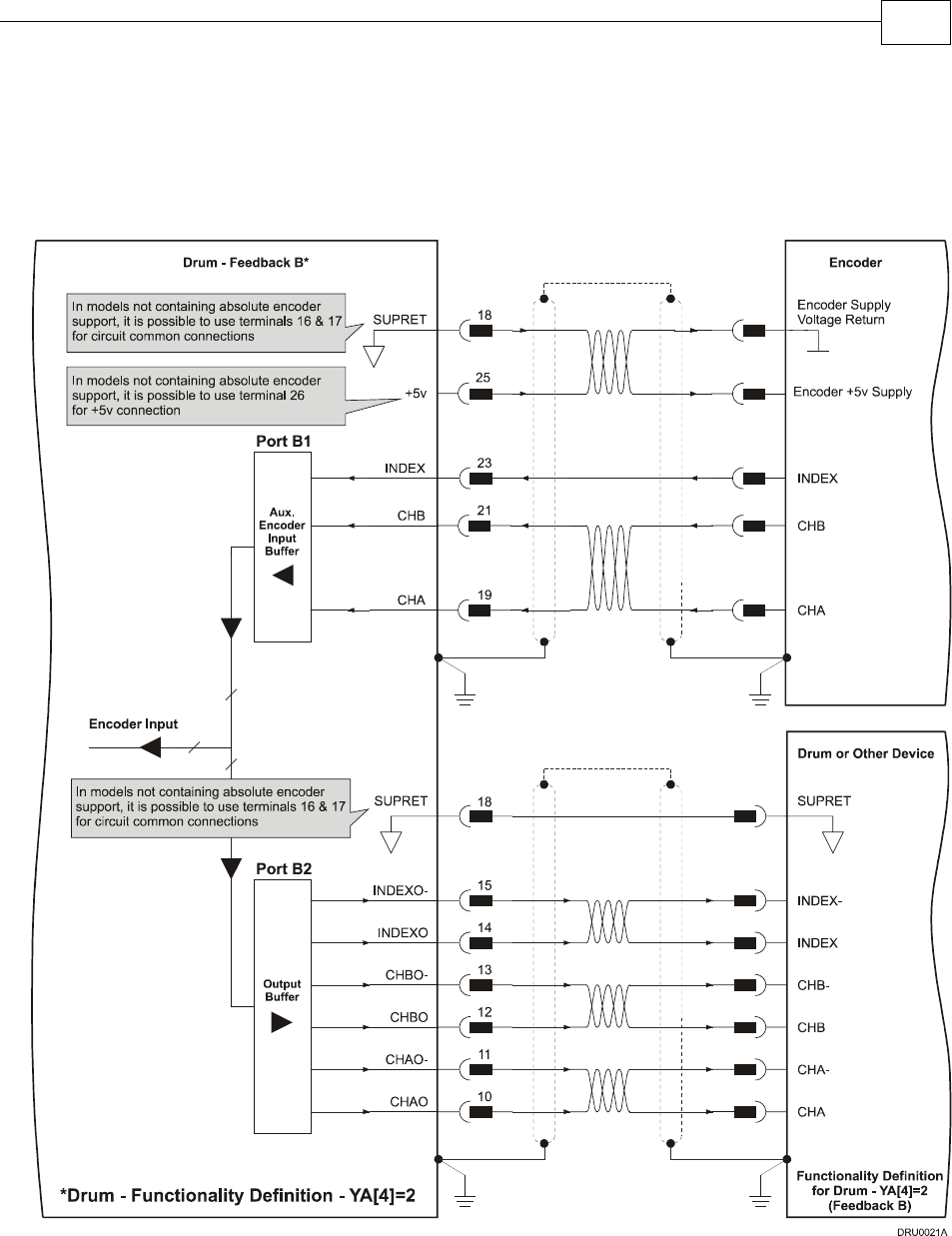
3.4.6 Auxiliary Feedback (FEEDBACK B)
When using one of the auxiliary feedback options, the relevant functionality of FEEDBACK B
ports are software selected for that option. Refer to the SimplIQ Command Reference Manual for
detailed information about FEEDBACK B setup. When assembling the Main Feedback cable,
follow the instructions in Section 3.4.3 (Feedback Control and Communication Cable
Assemblies).
Note: the Feedback connector also supports Feedbacks A and B.
*
Drum Installation Guide Installation
MAN-DRUIG (Ver. 1.0)
3-29
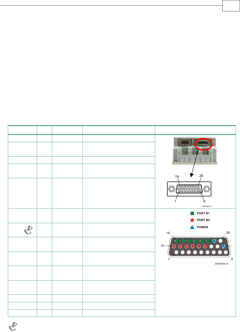
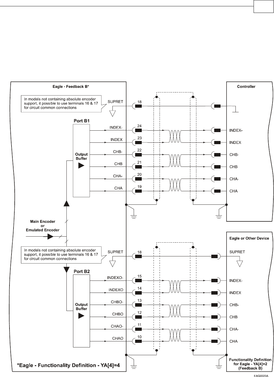
3.4.6.1 Main Encoder Buffered Outputs or Emulated Encoder
Outputs Option on FEEDBACK B (YA[4]=4)
Through FEEDBACK B (Ports B1 and B2) the Drum can provide two simultaneous
buffered main, or emulated, encoder signals to other controllers or drives. This option
can be used when:
The Drum is used as a current amplifier to provide position data to the position
controller.
The Drum is used in velocity mode, to provide position data to the position
controller.
The Drum is used as a master in Follower or ECAM mode.
Below are the signals on the Auxiliary Feedback ports when set up to run as a buffered
outputs or emulated outputs of the main encoder (on FEEDBACK A):
Port Pin Signal Function Pin Position
B2 10 CHAO Buffered channel A output
B2 11 CHAO-
Buffered channel A
complement output
B2 12 CHBO Buffered channel B output
B2 13 CHBO-
Buffered channel B
complement output
B2 14 INDEXO Buffered Index output
B2 15 INDEXO-
Buffered Index complement
output
PWR 18 SUPRET Encoder supply voltage
return/COMRET
B1 19 CHA Auxiliary channel A high
output
B1 20 CHA- Auxiliary channel A low
output
B1 21 CHB Auxiliary channel B high
output
B1 22 CHB- Auxiliary channel B low
output
B1 23 INDEX Auxiliary Index high output
B1 24 INDEX- Auxiliary Index low output
PWR 25 +5V Encoder supply voltage
26 Pin high density
D-sub Socket
Note: In models not containing absolute encoder support, it is possible to use
terminals 16 and 17 for SUPRET connections.
Table 3-8: Main Encoder Buffered Outputs or Emulated Encoder Outputs on FEEDBACK B -
Pin Assignments
J4
Female
Drum Installation Guide Installation
MAN-DRUIG (Ver. 1.0)
3-30
FEEDBACK B on the “top” of the Drum has a 26-pin high density D-sub socket. Connect the
Auxiliary Feedback cable, from the controller or other device, to FEEDBACK B using a 26-pin,
high density D-Sub plug with a metal housing. When assembling the Auxiliary Feedback
cable, follow the instructions in Section 3.4.3 (Feedback Control and Communication Cable
Assemblies).
Figure 3-21: Main Encoder Buffered Output or Emulated Encoder Output on FEEDBACK B -
Connection Diagram
Drum Installation Guide Installation
MAN-DRUIG (Ver. 1.0)
3-31
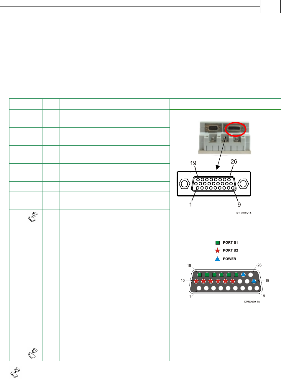
3.4.6.2 Differential Auxiliary Encoder Input Option on
FEEDBACK B (YA[4]=2)
The Drum can be used as a slave by receiving the position of the master encoder data (on Port
B1) in Follower or ECAM mode. In this mode Port B2 provides differential buffered
auxiliary outputs for the next slave axis in follower or ECAM mode.
Below are the signals on the Auxiliary Feedback port when set up to run as a differential
auxiliary encoder input:
Port Pin Signal Function Pin Position
B2 10 CHAO Buffered channel A
output
B2 11 CHAO- Buffered channel A
complement output
B2 12 CHBO Buffered channel B
output
B2 13 CHBO- Buffered channel B
complement output
B2 14 INDEXO Buffered Index output
B2 15 INDEXO- Buffered Index
complement output
PWR 18 SUPRET Encoder supply voltage
return/COMRET
B1 19 CHA Auxiliary channel A
high input
B1 20 CHA- Auxiliary channel A low
input
B1 21 CHB Auxiliary channel B
high input
B1 22 CHB- Auxiliary channel B low
input
B1 23 INDEX Auxiliary Index high
input
B1 24 INDEX- Auxiliary Index low
input
PWR 25 +5V Encoder supply voltage
26 Pin high density
D-Sub Socket
Note: In models not containing absolute encoder support, it is possible to use
terminals 16 and 17 for SUPRET connections and use terminal 26 for +5V connection.
Table 3-9: Differential Auxiliary Encoder Input Option on FEEDBACK B – Pin Assignments
J4
Female
Drum Installation Guide Installation
MAN-DRUIG (Ver. 1.0)
3-32
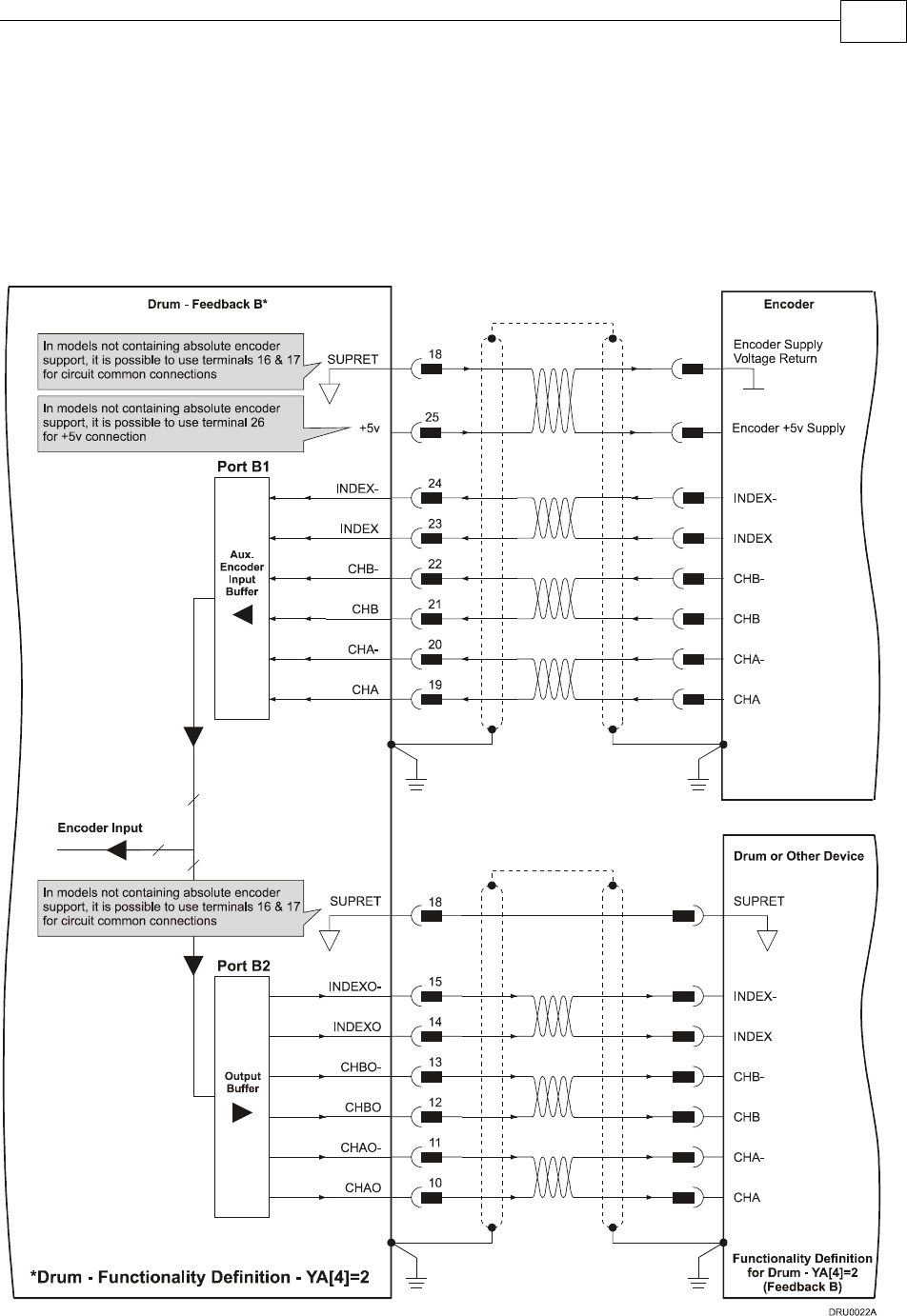
FEEDBACK B on the “top” of the Drum has a 26-pin high density D-sub socket. Connect the
Auxiliary Feedback cable from the feedback device to FEEDBACK B using a 26-pin, high
density D-Sub plug with a metal housing. When assembling the Auxiliary Feedback cable,
follow the instructions in Section 3.4.3 (Feedback Control and Communication Cable
Assemblies).
Figure 3-22: Differential Auxiliary Encoder Input Option on FEEDBACK B -
Connection Diagram
Drum Installation Guide Installation
MAN-DRUIG (Ver. 1.0)
3-33
3.4.6.3 Single-ended Auxiliary Input Option on FEEDBACK B
(YA[4]=2)
The Drum can be used as a slave by receiving the position data (on Port B1) of the master
encoder in Follower or ECAM mode. In this mode Port B2 provides differential buffered
auxiliary outputs for the next slave axis in Follower or ECAM mode.
Below are the signals on the Auxiliary Feedback ports when set up to run as a single-ended
auxiliary input:
Port Pin Signal Function Pin Position
B2 10 CHAO Channel A output
B2 11 CHAO- Channel A
complement output
B2 12 CHBO Channel B output
B2 13 CHBO- Channel B
complement output
B2 14 INDEXO Index output
B2 15 INDEXO- Index complement
output
26 Pin high density D-Sub Plug
PWR 18 SUPRET Encoder supply
voltage return/
COMRET
B1 19 CHA Auxiliary channel A
high input
20 NC Do not connect this
pin
B1 21 CHB Auxiliary channel B
high input
22 NC Do not connect this
pin
B1 23 INDEX Auxiliary Index high
input
24 NC Do not connect this
pin
PWR 25 +5V Encoder supply
voltage
26 Pin high density
D-Sub Socket
Note: In models not containing absolute encoder support, it is possible to use
terminals 16 and 17 for SUPRET connections and use terminal 26 for +5V connection.
Table 3-10: Single-ended Auxiliary Encoder Option on FEEDBACK B - Pin Assignments
J4
Female
Drum Installation Guide Installation
MAN-DRUIG (Ver. 1.0)
3-34
FEEDBACK B on the “top” of the Drum has a 26-pin high density D-sub socket. Connect the
Auxiliary Feedback cable from the feedback device to FEEDBACK B using a 26-pin, high
density D-Sub plug with a metal housing. When assembling the Auxiliary Feedback cable,
follow the instructions in Section 3.4.3 (Feedback Control and Communication Cable
Assemblies).
Figure 3-23: Single-ended Auxiliary Input Option on FEEDBACK B - Connection Diagram
Drum Installation Guide Installation
MAN-DRUIG (Ver. 1.0)
3-35
3.4.6.4 Pulse-and-Direction Input Option on FEEDBACK B
(YA[4]=0)
This mode is used for input of differential or single-ended pulse-and-direction position
commands on Port B1. In this mode Port B2 provides differential buffered pulse-and-
direction outputs for another axis.
Below are the signals on the Auxiliary Feedback ports when set up to run as a single-ended
pulse-and-direction input:
Port Pin Signal Function Pin Position
B2 10 CHAO Channel A output
B2 11 CHAO- Channel A complement output
B2 12 CHBO Channel B output.
B2 13 CHBO- Channel B complement output
14 NC Do not connect this pin
15 NC Do not connect this pin
PWR 18 SUPRET Encoder supply voltage return/
COMRET
B1 19 PULS/CHA Pulse/Auxiliary channel A high
input
26 Pin D-Sub
High Density Plug
20 NC Do not connect this pin
B1 21 DIR/CHB Direction/Auxiliary channel B
high input
22 NC Do not connect this pin
23 NC Do not connect this pin
24 NC Do not connect this pin
PWR 25 +5V Encoder supply voltage 26 Pin D-Sub Socket
Note: In models not containing absolute encoder support, it is possible to use
terminals 16 and 17 for SUPRET connections.
Table 3-11: Single Ended Pulse-and-Direction Auxiliary Encoder Pin Assignment on
FEEDBACK B
FEEDBACK B on the “top” of the Drum has a 26-pin high density D-sub socket. Connect the
Auxiliary Feedback cable from the Pulse and Direction Controller to FEEDBACK B using a
26-pin, high density D-Sub plug with a metal housing. When assembling the Auxiliary
Feedback cable, follow the instructions in Section 3.4.3 (Feedback Control and
Communication Cable Assemblies).
J4
Female
Drum Installation Guide Installation
MAN-DRUIG (Ver. 1.0)
3-36
Figure 3-24: Single-Ended Pulse-and-Direction Input Option on FEEDBACK B - Connection
Diagram
Drum Installation Guide Installation
MAN-DRUIG (Ver. 1.0)
3-37
Below are the signals on the Auxiliary Feedback ports when set up to run as a differential
pulse-and-direction input:
Port Pin Signal Function Pin Position
B2 10 CHAO Channel A output
B2 11 CHAO- Channel A complement output
B2 12 CHBO Channel B output.
B2 13 CHBO- Channel B complement output
14 NC Do not connect this pin
15 NC Do not connect this pin
PWR 18 SUPRET Encoder supply voltage return/
COMRET
B1 19 PULS/CHA Pulse/Auxiliary channel A high
input
26 Pin D-Sub High Density
Plug
B1 20 PULS-/CHA- Pulse/Auxiliary channel A
complement high input
B1 21 DIR/CHB Direction/Auxiliary channel B
high input
B1 22 DIR-/CHB- Direction/Auxiliary channel B
complement high input
23 NC Do not connect this pin
24 NC Do not connect this pin
PWR 25 +5V Encoder supply voltage
26 Pin D-Sub Socket
Note: In models not containing absolute encoder support, it is possible to use
terminals 16 and 17 for SUPRET connections.
Table 3-12: Differential Pulse-and-Direction Auxiliary Encoder Pin Assignment on
FEEDBACK B
J4
Female
Drum Installation Guide Installation
MAN-DRUIG (Ver. 1.0)
3-38
Figure 3-25: Differential Pulse-and-Direction Input Option on FEEDBACK B - Connection
Diagram
Drum Installation Guide Installation
MAN-DRUIG (Ver. 1.0)
3-39
3.4.7 I/O Cables
The Drum has one I/O port, J3. J3 is a general I/O which can be used to connect 6 digital
inputs, 2 digital outputs and 1 analog input.
I/O J3 Port
Digital Input 6
Digital Output 2
Analog Input 1
3.4.7.1 General I/O Port (J3)
Port J3 has a 15-pin high density D-Sub plug. When assembling this I/O cable, follow the
instructions in Section 3.4.3 (Feedback Control and Communication Cable Assemblies) using
a 15-pin high density metal case D-sub female connector (socket).
Pin Signal Function Pin Position
1 ANLIN+ Analog input +
2 ANLIN- Analog input -
3 ANLRET Analog return
4 OUTRET2 Programmable output return 2
5 OUT2 Programmable output 2
6 IN6 Programmable input 6
7 INRET General input return
8 INRET General input return
9 OUTRET 1 Programmable output return 1
10 OUT1 Programmable output 1
11 IN1 Programmable input 1
12 IN2 Programmable input 2
13 IN3 Programmable input 3
14 IN4 Programmable input 4
15 IN5 Programmable input 5
Table 3-13: J3 I/O Cable - Pin Assignments
J3
Male
Drum Installation Guide Installation
MAN-DRUIG (Ver. 1.0)
3-40
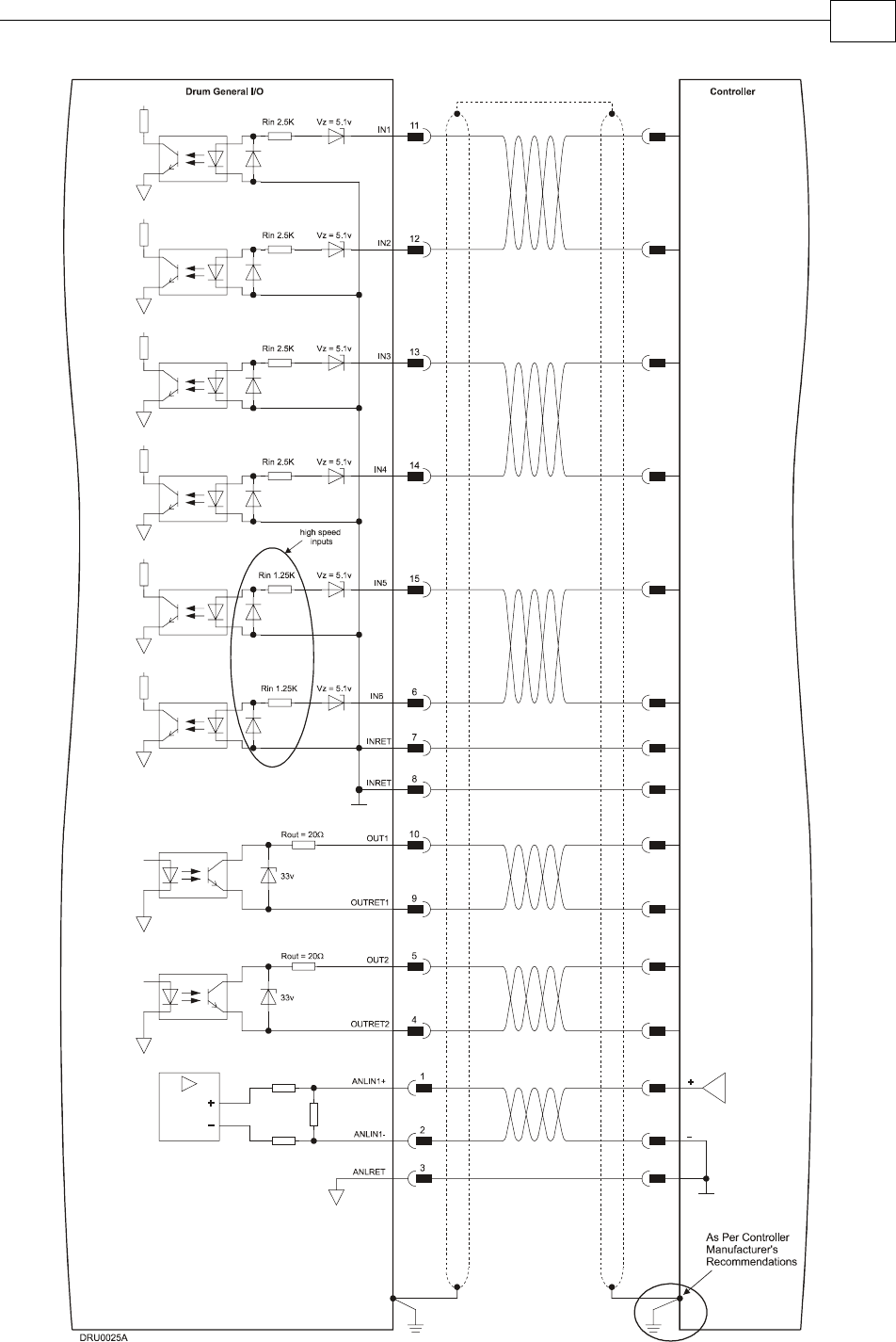
Figure 3-26: General J1 I/O Connection Diagram
Drum Installation Guide Installation
MAN-DRUIG (Ver. 1.0)
3-41
3.4.8 Communication Cables
The communication cables use a 9-pin D-sub plug that connect to the RS-232 and 9-pin D-sub
socket that connects to the CANopen ports on the Drum.
The communication interface may differ according to the user’s hardware. The Drum can
communicate using the following options:
a. RS-232, full duplex
b. CANopen
RS-232 communication requires a standard, commercial 3-core null-modem cable connected
from the Drum to a serial interface on the PC. The interface is selected and set up in the
Composer software.
In order to benefit from CANopen communication, the user must have an understanding of
the basic programming and timing issues of a CANopen network. The interface is electrically
isolated by optocouplers.
For ease of setup and diagnostics of CAN communication, RS-232 and CANopen can be used
simultaneously.
3.4.8.1 RS-232 Communication
Notes for connecting the RS-232 communication cable:
Use a 24, 26 or 28 AWG twisted pair shielded cable (24 AWG cable is recommended).
The shield should have aluminum foil covered by copper braid with a drain wire.
Connect the shield to the ground of the host (PC). Usually, this connection is
soldered internally inside the connector at the PC end. You can use the drain wire to
facilitate connection.
Use only a D-sub connector with a metal housing.
Attach the braided shield tightly to the metal housing of the D-type connector.
When assembling the Communication cable, follow the instructions in Section 3.4.3
(Feedback Control and Communication Cable Assemblies).
Pin Signal Function Pin Location
1 — —
2 Tx RS-232 transmit
3 Rx RS-232 receive
4 — —
5 COMRET Communication return
6 — —
7 — —
8 — —
Table 3-14: RS-232 Cable - Pin Assignments
J2
Female
Drum Installation Guide Installation
MAN-DRUIG (Ver. 1.0)
3-42
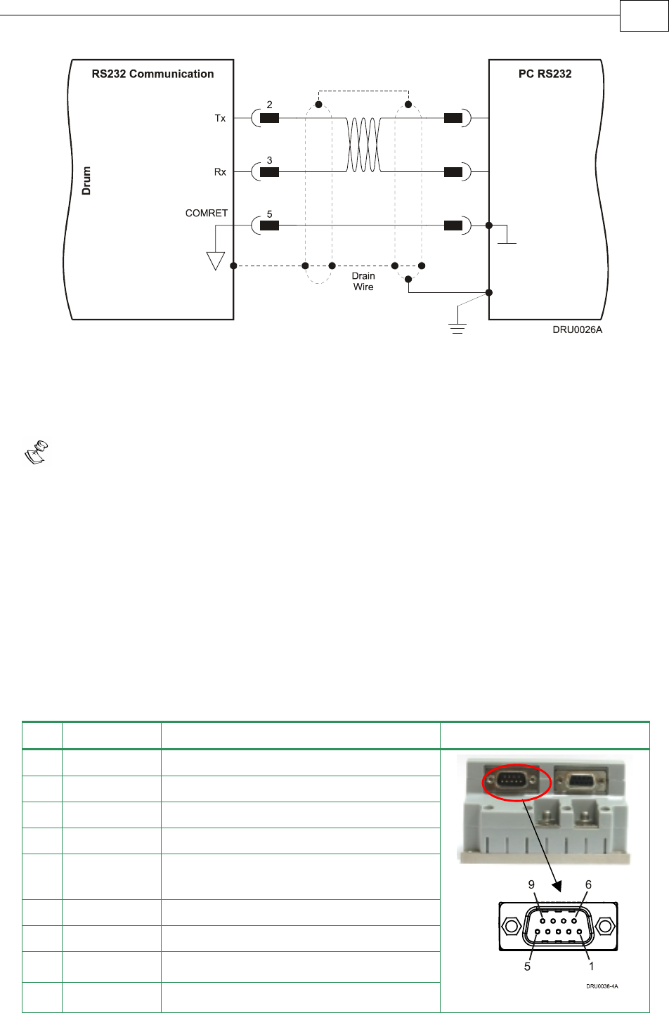
Figure 3-27: RS-232 Connection Diagram
3.4.8.2 CANopen Communication
Notes for connecting the CANopen communication cable:
Use 24, 26 or 28 AWG twisted pair shielded cables (24 AWG cable is recommended).
For best results, the shield should have aluminum foil and covered by copper braid
with a drain wire
Connect the shield to the ground of the host (PC). Usually, this connection is
soldered internally inside the connector at the PC end. You can use the drain wire to
facilitate connection.
Use only a D-sub connector with a metal housing.
Attach the braid shield tightly to the metal housing of the D-type connector.
Connect a termination 120-ohm resistor at each of the two ends of the network cable.
When assembling the Communication cable, follow the instructions in Section 3.4.3
(Feedback Control and Communication Cable Assemblies).
Pin Signal Function Pin Position
1 — —
2 CAN_L CAN_L busline (dominant low)
3 CAN_GND CAN ground
4 — —
5 CAN_SHLD Shield, attach to the metal housing of
the D-type
6 CAN_GND CAN Ground
7 CAN_H CAN_H busline (dominant high)
8 — Do not connect
9 — Do not connect
Table 3-15: CANopen Cable - Pin Assignments
J1
Male
Drum Installation Guide Installation
MAN-DRUIG (Ver. 1.0)
3-43
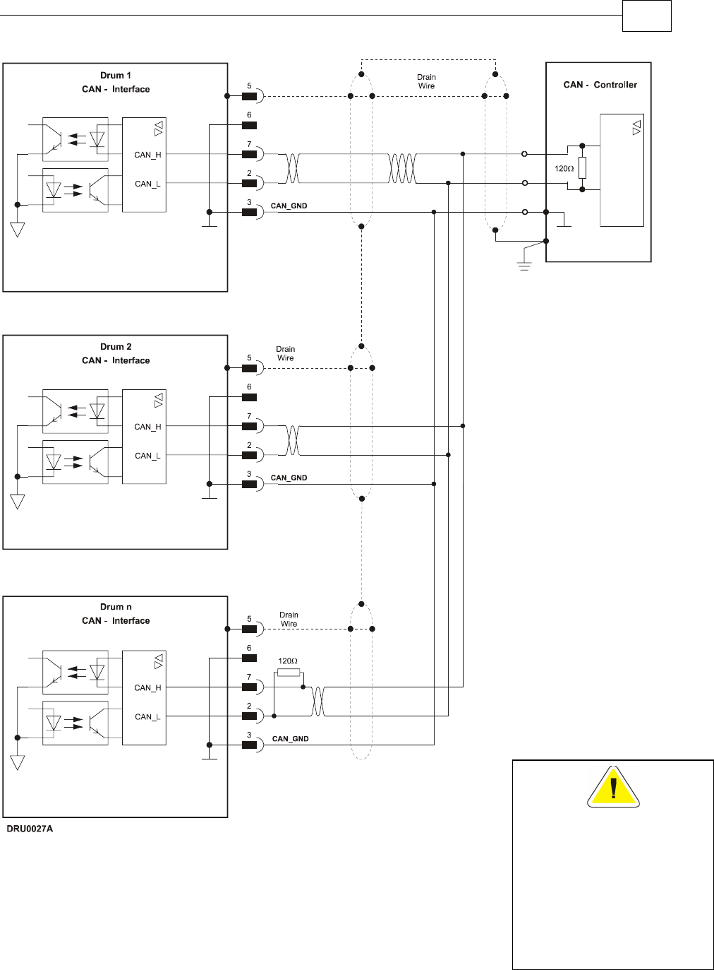
Figure 3-28: CANopen Connection Diagram
Caution:
When installing CANope
n
communications, ensure
that each servo drive is
allocated a unique ID.
Otherwise, the CANope
n
network may hang.
Drum Installation Guide Installation
MAN-DRUIG (Ver. 1.0)
3-44

3.5 DC Power Supply
The DC power supply can be at any voltage in the range defined in the technical
specifications (the Appendix of this guide). The supply source must comply with the safety
aspects of the relevant requirements, in accordance with the most recent version of the
standard EN60950 or equivalent Low Voltage Directive Standard, all according to the
applicable over-voltage category. If the power source to the power supply is the AC line
(through an isolated or a non-isolated transformer), safety margins must be considered, in
order to avoid activating the under/over voltage protection due to line variations and/or
voltage drop under load.
In addition to the above, the transformer must comply with the safety aspects of the relevant
requirements in accordance with the most recent version of the standard EN60742 (Isolating
and Safety Isolating Transformers). The nominal DC bus voltage should be in the following
range:
1.2 Vdcmin < Vdc < 0.9 Vdcmax
Where:
Vdcmin is the minimum DC bus
Vdcmax is the maximum DC bus
The transformer power should be calculated such that it will be able to deliver power to the
amplifier (including peak power) without significant voltage drops.
The power supply should be located as close as possible to the amplifier. While driving high-
inertia loads, the power supply must be equipped with a shunt regulator; otherwise, the
amplifier will be disabled whenever the capacitors are charged above the maximum voltage,
during motor break down.
3.5.1 Powering Up
After the Drum has been mounted, check that the cables are intact. The Drum servo drive is
then ready to be powered up.
Caution:
Before applying power, ensure that the DC supply is within the range
specified for your specific type of Drum and that the proper
plus-minus connections are in order.
3.5.2 Initializing the System
After the Drum has been connected and mounted, the system must be set up and initialized.
This is accomplished using the Composer, Elmo’s Windows-based software application. Install
the application and then perform setup and initialization according to the directions in the
Composer Software Manual.
Drum Installation Guide Installation
MAN-DRUIG (Ver. 1.0)
3-45
3.6 Heat Dissipation
For full power output capability the Drum is designed to be mounted on an external heatsink.
It is highly recommended that the “Wall” on which the Drum is mounted will have heat
dissipation capabilities. The Drum at “free air convection” (without an additional heatsink)
can dissipate around 12 W for 40 °C ambient temperature and not exceeding 80 °C on the
heatsink.
When “Free Air Convection” is sufficient for the application it is recommended to leave
approximately 10 mm of space between the Drum's heatsink and any other assembly.
3.6.1 Drum Thermal Data
• Free air convection thermal resistance (θ): Approximately 3.6 – 4 °C/W.
• Thermal time constant: Approximately 40 minutes/ 2400 seconds (thermal time
constant means that the Drum will reach 2/3 of its final temperature after 4 minutes).
• Self heat dissipation capability (no external heatsink): 12W for 40 °C/W temperature
rise.
• Shut-off temperature: 86 °C – 88 °C (measured on the heatsink).
• The thermal resistance when connecting to an external heat sink:
oThe surface of the external heatsink is 50um: 0.18 °C/W.
oThermal conductive compound. By proper Smearing of the surface a
significant improvement of the thermal resistance is achieved: 0.13 °C/W
3.6.2 Heat Dissipation Data
Heat Dissipation is shown in graphically below:
Power Dissipation 60V series
0
10
20
30
40
50
60
70
80
90
100
0 122030405060708090
Motor's Current (Ampere)
Power Dissipation (W)
12VDC
20VDC
30VDC
40VDC
50VDC
56VDC
Sta
n
da
r
d
4
0
°
°°
°
C
Am
b
i
e
n
t
T
e
m
p
.
Heatsink
Required
Heatsink
not
Required
Drum Installation Guide Installation
MAN-DRUIG (Ver. 1.0)
3-46
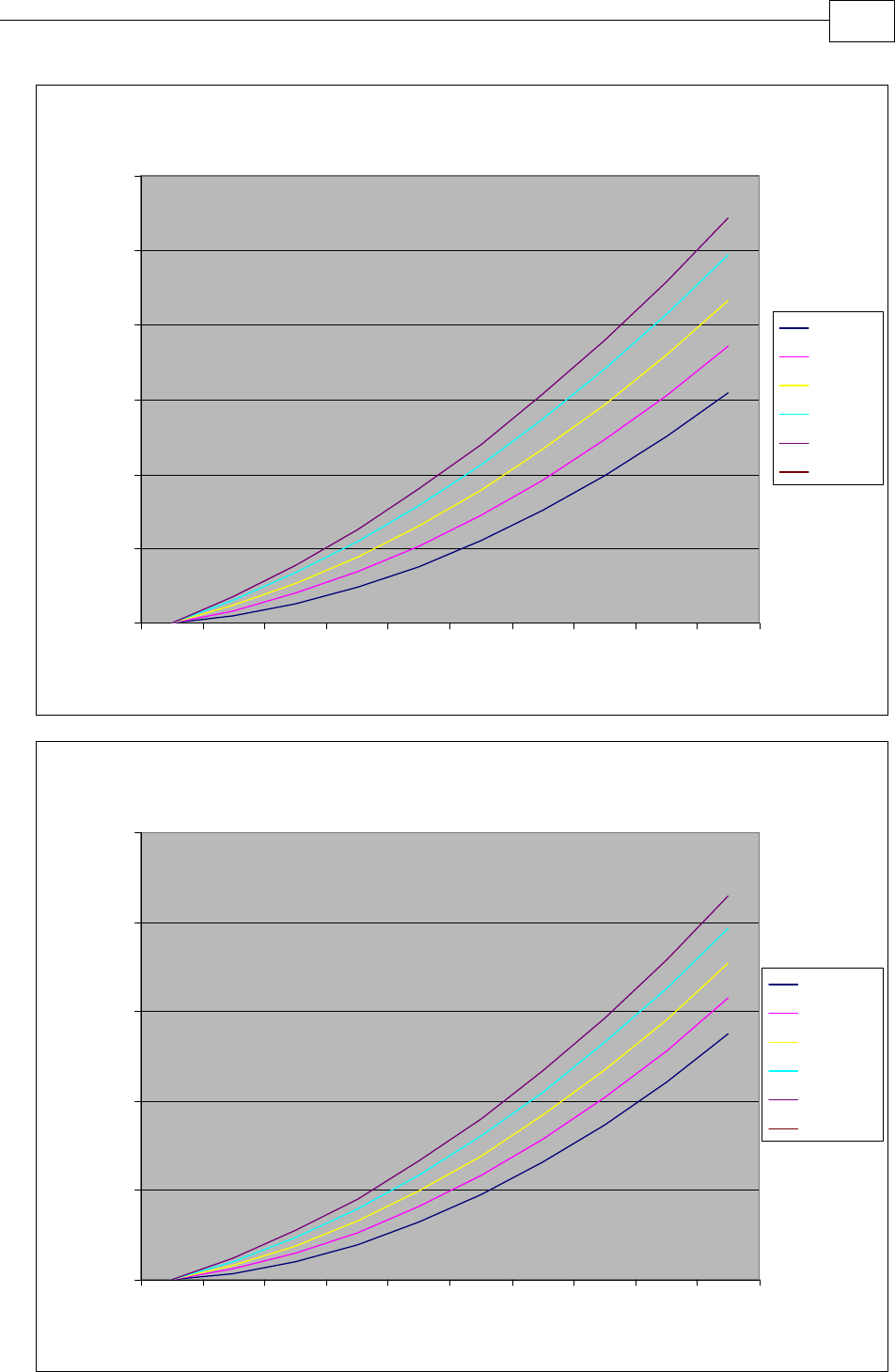
Power Dissipation 100V series
0
20
40
60
80
100
120
0 8.3 16.7 25.0 33.3 41.7 50.0 58.3 66.7 75.0
Motor's Current (Ampere)
Power Dissipation (W)
20VDC
40VDC
60VDC
80VDC
96VDC
Power Dissipation 200V series
0
50
100
150
200
250
0 6.7 13.3 20.0 26.7 33.3 40.0 46.7 53.3 60.0
Motor's Current (Ampere)
Power Dissipation (W)
40VDC
80VDC
120VDC
160VDC
196VDC
Drum Installation Guide Installation
MAN-DRUIG (Ver. 1.0)
3-47

3.6.3 How to Use the Charts
The charts above are based upon theoretical worst-case conditions. Actual test results show
30% - 50% better power dissipation.
To determine if your application needs a heatsink:
1. Allow maximum heatsink temperature to be 80°C or less (shunt down is 6 °C – 8 °C
higher).
2. Determine the ambient operating temperature of the Drum as ≤ 40 °C.
3. Calculate the allowable temperature increase as follows:
• for an ambient temperature of 40°C , ∆T= 80 °C – 40 °C = 40 °C
4. Use the chart to find the actual dissipation power of the drive. Follow the voltage
curve to the desired output current and then find the dissipated power.
5. If the dissipated power is below 12 W the Drum needs no additional cooling.
Note: The chart above shows that no heatsink is needed when the heatsink temperature is
80 °C, ambient temperature is 40 °C and heat dissipated is 4 W.
Drum Installation Guide Installation
MAN-DRUIG (Ver. 1.0)
3-48

Appendix: Drum Technical Specifications
A.1 Features
A.1.1 Motion Control Modes
• Current/Torque - up to 14 kHz sampling rate
• Velocity - up to 7 kHz sampling rate
• Position - up to 3.5 kHz sampling rate
A.1.2 Advanced Positioning Control Modes
• PTP, PT, PVT, ECAM, Follower, Dual Loop
• Fast event capturing inputs
• Fast output compare (OC)
• Motion Commands: Analog, PWM, digital (SW) and Pulse and Direction
A.1.3 Advanced Filters and Gain Scheduling
• “On-the-Fly” gain scheduling of current and velocity
• Velocity and position with “1-2-4” PIP controllers
• Automatic commutation alignment
• Automatic motor phase sequencing
A.1.4 Fully Programmable
• Third generation programming structure with motion commands –
“Metronome”
• Event capturing interrupts
• Event triggered programming
• 32 KB memory
A.1.5 Feedback Options
• Incremental Encoder – up to 20 Mega-Counts (5 Mega-Pulse) per second
• Digital Halls – up to 2 kHz
• Tachometer and potentiometer (optional)
• Incremental Encoder with Digital Halls for commutation – up to 20 Mega-
Counts per second for encoder
• Interpolated Analog Encoder (optional)
Sine/Cosine Encoder– up to 250 kHz
Internal Interpolation - up to x4096
Automatic correction of amplitude mismatch, phase mismatch, signal offset
Differential encoder buffered outputs
• Resolver (optional)
Programmable 10~15 bit resolution
Up to 512 revolution per seconds (RPS)
Encoder outputs
A, B, Index
Differential encoder buffered outputs
Quadrate
Drum Installation Guide Drum Technical Specifications
MAN-DRUIG (Ver. 1.0)
A-1

• Absolute Encoder - Heidenhain 2.1 and Stegmann
Sine/Cosine Encoder– up to 250 kHz
Internal Interpolation - up to x4096
Automatic correction of amplitude mismatch, phase mismatch, signal offset
Differential encoder buffered outputs
• Auxiliary Encoder inputs (ECAM, follower, etc.)
A, B, Index
Differential encoder buffered outputs
Quadrate
A.1.6 Input/Output
• Analog Input– up to 14-bit resolution
• Six programmable Digital Inputs, optically isolated, PLC level
Inhibit/Enable motion
Software and analog reference stop
Motion limit switches
Begin on input
Abort motion
Homing
General-purpose
• Fast event capture inputs, optically isolated
• Two programmable Digital Outputs, optically isolated (open, emitter and collector)
Brake Control
Amplifier fault indication
General-purpose
Servo enable indication
• Differential emulated outputs of the resolver, interpolated analog encoder,
tachometer and absolute encoder
• Fast output compare (OC), optically isolated
• Pulse and Direction inputs (single-ended and differential)
• PWM current command output
A.1.7 Built-In Protection
• Software error handling
• Abort (hard stops and soft stops)
• Status reporting
• Protection against:
Shorts between motor power outputs
Shorts between motor power outputs and power input/return
Failure of internal power supplies
Over temperature
Cont. temperature measurement. Temperature can be read on the fly,
Warning can be initiated X degrees before temp disable is activated.
Over/Under voltage
Loss of feedback
Drum Installation Guide Drum Technical Specifications
MAN-DRUIG (Ver. 1.0)
A-2

Following error
Current limits
Loss of commutation signals
Communication error
A.1.8 Accessories
• Cable Kit
A.1.9 Automatic Procedures
• Commutation alignment
• Phase sequencing
• Current loop offset adjustment
• Current loop gain tuning
• Current gain scheduling
• Velocity loop offset adjustment
• Velocity gain tuning
• Velocity gain scheduling
• Position gain tuning
Drum Installation Guide Drum Technical Specifications
MAN-DRUIG (Ver. 1.0)
A-3

A.2 Dimensions
Drum Installation Guide Drum Technical Specifications
MAN-DRUIG (Ver. 1.0)
A-4

A.3 Power Ratings
Feature Units 70/48 70/60 R90/60 50/100 R75/100 35/200 R60/200 18/400
Minimum supply voltage VDC 11 14 23 46 92
Nominal supply voltage VDC 42 50 85 170 340
Maximum supply voltage VDC 48 59 95 195 390
Maximum continuous
power output W 2700 3400 4300 4000 6000 5600 9600 5600
Efficiency at rated power
(at nominal conditions) % > 97
Maximum output voltage 97% of DC bus voltage at f=22 kHz
Amplitude sinusoidal/DC
continuous current A 70 70 90 50 75 35 60 18
Sinusoidal continuous
RMS current limit (Ic) A 50 50 63 35 53 25 42 12.7
Peak current limit A 2 x Ic 2 x Ic No Peak 2 x Ic No Peak 2 x Ic No Peak 2 x Ic
Weight g (oz) 700 g (24.7 oz)
Dimensions mm (in) 134 x 95 x 60 (5.3" x 3.7" x 2.4")
Digital in/Digital
out/Analog in 6/2/1
Mounting method Panel mount
A.4 Environmental Conditions
Feature Details
Ambient operating temperature 0 °C – 40 °C (32 °F – 104°F)
Storage temperature -20 °C – 85 °C (-4 °F – +185 °F)
Maximum humidity 90% non-condensing
Protection level
Drum Installation Guide Drum Technical Specifications
MAN-DRUIG (Ver. 1.0)
A-5

A.4.1 Auxiliary Supply
Feature Details
Auxiliary power supply Isolated DC source only
Auxiliary supply input voltage 12 VDC ~ 195 VDC
Auxiliary supply input power < 4 VA (this includes the 5V/200 mA load for
the main encoder only)
< 5.5 VA (this includes the 5V/400 mA load on
the main encoder and feedback B)
A.5 Control Specifications
A.5.1 Current Loop
Feature Details
Controller type Vector, digital
Compensation for bus voltage
variations
“On-the-fly” automatic gain scheduling
Motor types AC brushless (sinusoidal)
DC brushless (trapezoidal)
DC brush
Linear motors
Moving coils
Current control Fully digital
Sinusoidal with vector control
Programmable PI control filter based on a
pair of PI controls of AC current signals and
constant power at high speed
Current loop bandwidth < 2.5 kHz
Current loop sampling time Programmable 70 - 100 µsec
Current loop sampling rate Up to 16 kHz; default 11 kHz
Drum Installation Guide Drum Technical Specifications
MAN-DRUIG (Ver. 1.0)
A-6

A.5.2 Velocity Loop
Feature Details
Controller type PI
Velocity control Fully digital
Programmable PI and FFW control filters
"On-the-fly" gain scheduling
Automatic, manual and advanced manual tuning
Velocity and position feedback
options
Incremental Encoder
Absolute Encoder- Heidenhain and Stegmann
Digital Halls
Interpolated Analog (sin/cos) Encoder (optional)
Resolver (optional)
Tachometer and Potentiometer (optional)
Velocity loop bandwidth < 350 Hz
Velocity loop sampling time 140 - 200 µsec (x2 current loop sample time)
Velocity loop sampling rate up to 8 kHz; default 5.5 kHz
Velocity command options Analog
Internally calculated by either jogging or step
Note: All software-calculated profiles support
on-the-fly changes.
A.5.3 Position Loop
Feature Details
Controller type “1-2-4” PIP
Position command options Software
Pulse and Direction
Analog Potentiometer
Position loop bandwidth < 80 Hz
Position loop sampling time 280 - 400 µsec (x 4 current loop sample time)
Position loop sampling rate up to 4 kHz; default 2.75 kHz
Drum Installation Guide Drum Technical Specifications
MAN-DRUIG (Ver. 1.0)
A-7
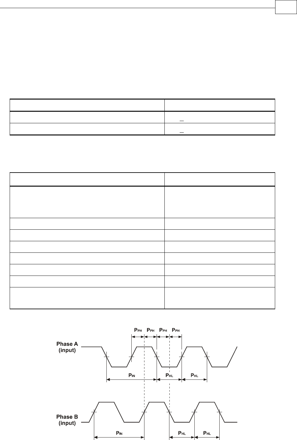
A.6 Feedbacks
A.6.1 Feedback Supply Voltage
The Drum has two feedback ports (main and auxiliary). The drives supply voltage to the
main and auxiliary feedback devices (200 mA to the main feedback and 200 mA to the
auxiliary feedback).
Feature Details
Main encoder supply voltage 5 V +5% @ 200 mA
Auxiliary encoder supply voltage 5 V +5% @ 200 mA
A.6.2 Main Feedback Options
A.6.2.1 Incremental Encoder Input
Feature Details
Encoder format A, B and Index
Differential
Quadrature
Interface RS-422
Input resistance Differential: 120 Ω
Maximum incremental encoder frequency Maximum absolute: 5 MHz pulses
Minimum quadrature input period (PIN) 112 nsec
Minimum quadrature input high/low period (PHL) 56 nsec
Minimum quadrature phase period (PPH) 28 nsec
Maximum encoder input voltage range Common mode: ±7 V
Differential mode: ±7 V
Figure A-1: Main Feedback - Encoder Phase Diagram
Drum Installation Guide Drum Technical Specifications
MAN-DRUIG (Ver. 1.0)
A-8

A.6.2.2 Digital Halls
Feature Details
Halls inputs HA, HB, HC.
Single ended inputs
Built in hysteresis of 1 V for noise immunity
Input voltage Nominal operating range: 0 V < VIn_Hall < 5 V
Maximum absolute: -1 V < VIn_Hall < 15 V
High level input voltage: V InHigh > 2.5 V
Low level input voltage: V InLow < 1 V
Input current Sink current (when input pulled to the
common): 3 mA
Maximum frequency fMAX : 2 kHz
A.6.2.3 Interpolated Analog Encoder (Sine/Cosine)
Feature Details
Analog encoder format Sine and Cosine signals
Analog input signal level Offset voltage: 2.2 V – 2.8 V
Differential, 1 V peak to peak
Input resistance Differential 120 Ω
Maximum analog signal frequency fMAX : 250 kHz
Interpolation multipliers Programmable: x4 to x4096
Maximum “counts” frequency 80 mega-counts/sec “internally”
Automatic errors correction Signal amplitudes mismatch
Signal phase shift
Signal offsets
Encoder outputs See Auxiliary Encoder Outputs specifications ( 0)
A.6.2.4 Resolver
Feature Details
Resolver format Sine/Cosine
Differential
Input resistance Differential 2.49 kΩ
Resolution Programmable: 10 ~ 15 bits
Maximum electrical frequency (RPS) 512 revolutions/sec
Resolver transfer ratio 0.5
Drum Installation Guide Drum Technical Specifications
MAN-DRUIG (Ver. 1.0)
A-9

Feature Details
Reference frequency 1/Ts (Ts = sample time in seconds)
Reference voltage Supplied by the Drum
Reference current up to ±50 mA
Encoder outputs See Auxiliary Encoder Output specifications
( 0)
A.6.2.5 Tachometer*
Feature Details
Tachometer format Differential
Maximum operating differential
voltage for TAC1+, TAC1-
±20 V
Maximum absolute differential input
voltage for TAC1+, TAC1-
±25 V
Maximum operating differential
voltage for TAC2+, TAC2-
±50 V
Maximum absolute differential input
voltage for TAC2+, TAC2-
±50 V
Input resistance for TAC1+, TAC1- 46 kΩ
Input resistance for TAC2+, TAC2- 100 kΩ
Resolution 14 bit
* Only one Tachometer port can be used at a time (either TAC1+/TAC1- or TAC2+/TAC2-).
TAC1+/TAC1- is used in applications with having a Tachometer of less than 20V.
TAC2+/TAC2- is used in applications with having a Tachometer of between 20V and 50V.
Drum Installation Guide Drum Technical Specifications
MAN-DRUIG (Ver. 1.0)
A-10

A.6.2.6 Potentiometer
Feature Details
Potentiometer Format Single-ended
Operating Voltage Range 0 ~ 5 V supplied by the Drum
Potentiometer Resistance 100 Ω ~ 1 kΩ … above this range, linearity is
affected detrimentally
Input Resistance 100 kΩ
Resolution 14 Bit
A.6.2.7 Absolute Encoder
Feature Details
Analog encoder format Sine and Cosine signals
Analog input signal level Offset voltage: 2.2 V – 2.8 V
Differential, 1 V peak to peak
Input resistance Differential 120 Ω
Maximum analog signal frequency fMAX : 250 kHz
Interpolation multipliers Programmable: x4 to x4096
Maximum “counts” frequency 80 mega-counts/sec "internally"
Automatic errors correction Signal amplitudes mismatch
Signal phase shift
Signal offsets
Encoder outputs See Encoder Outputs specifications (A.6.2.8)
A.6.2.8 Encoder Outputs
Feature Details
Encoder output format A, B, Index (not available in analog and
absolute encoders)
Differential outputs
Quadrature
Interface RS-422
Port B1 output current capability Driving differential loads of 200 Ω on
INDEX/INDEX-, CHB/CHB- and CHA/CHA- pairs
Drum Installation Guide Drum Technical Specifications
MAN-DRUIG (Ver. 1.0)
A-11

Feature Details
Port B2 output current capability
INDEXO/INDEXO-, CHBO/CHBO- and
CHAO/CHAO- pairs are not loaded
Available as options Two simultaneous buffered outputs of main-
incremental encoder input
Two simultaneous emulated encoder outputs
of analog or absolute encoder input
Two simultaneous emulated encoder outputs
of resolver input
Buffered output of auxiliary input
Maximum frequency fMAX : 5 MHz pulses/output
Index (marker) Length of pulse is one quadrature (one quarter
of an encoder cycle) and synchronized to A&B
A.6.3 Auxiliary Port
Feature Details
Encoder input, emulated output,
pulse and direction
A, B, Index
Differential or single ended
Quadrature
Output current capability 120 Ω
Available as options Emulated encoder outputs of analog encoder
Emulated encoder outputs of the resolver
Emulated encoder outputs of the potentiometer
Emulated encoder outputs of the tachometer
Main encoder buffered output
P&D buffered output
Emulated encoder outputs of the absolute
encoder
Maximum frequency fMAX : 5 MHz pulses/output
Edge separation between A & B
Programmable number of clocks to allow
adequate noise filtering at remote receiver of
emulated encoder signals
Index (marker): Length of pulse is one quadrature (one
quarter of an encoder cycle) and synchronized
to A&B
Drum Installation Guide Drum Technical Specifications
MAN-DRUIG (Ver. 1.0)
A-12
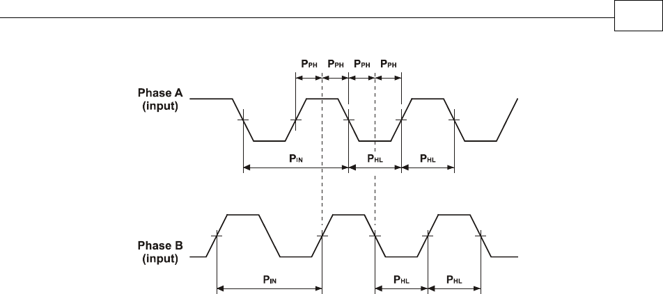
Figure A-2: Auxiliary Feedback - Encoder Phase Diagram
A.7 I/Os
The Drum has: 6 Digital Inputs 2 Digital Outputs 1 Analog Input
Drum Installation Guide Drum Technical Specifications
MAN-DRUIG (Ver. 1.0)
A-13
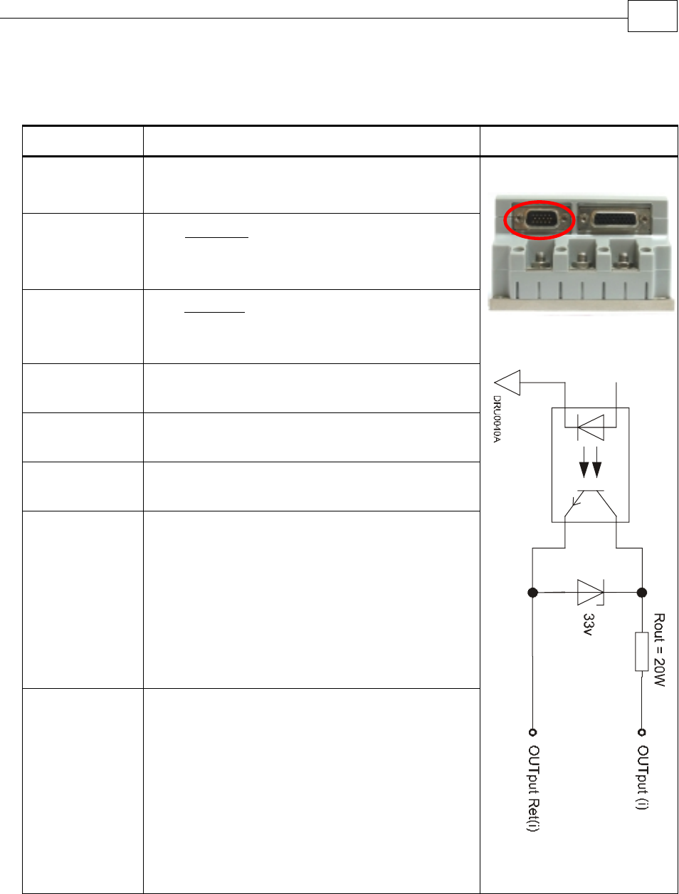
A.7.1 Digital Input Interfaces
Feature Details Connector Location
Type of input Optically isolated
Single ended
PLC level
Input current
Ω
−
=2500
5.6 VVin
Iin
* Iin = 2.2 mA @ Vin = 12 V
Input current
for high speed
inputs
Ω
−
=1250
5.6 VVin
Iin
* Iin = 4.4 mA @ Vin = 12 V
High-level
input voltage 12 V < Vin < 30 V, 24 V typical
Low-level
input voltage 0 V < Vin < 6.5 V
Minimum
pulse width > 4 x TS, where TS is sampling time
Execution time
(all inputs):
the time from
application of
voltage on
input until
execution is
complete
If input is set to one of the built-in functions —
Home, Inhibit, Hard Stop, Soft Stop, Hard and
Soft Stop, Forward Limit, Reverse Limit or
Begin — execution is immediate upon detection:
0<T<4xTS
If input is set to General input, execution
depends on program. Typical execution time: ≅
0.5 msec.
High-speed
inputs – 5 & 6
minimum pulse
width, in high-
speed mode
T < 5 µsec
Notes:
Home mode is high-speed mode and can
be used for fast capture and precise
homing
High speed input has a digital filter set to
same value as digital filter (EF) of main
encoder
Highest speed is achieved when turning on
optocouplers
Digital Input Schematic
Drum Installation Guide Drum Technical Specifications
MAN-DRUIG (Ver. 1.0)
A-14
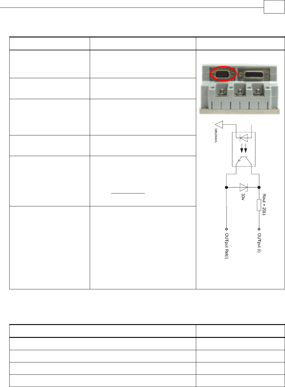
A.7.2 Digital Output Interface
Feature Details Connector Location
Type of output Optically isolated
Open collector and open
emitter
Maximum supply output
(Vcc)
30 V
Max. output current
Iout (max) (Vout = Low)
Iout (max) ≤ 15 mA
VOL at maximum output
voltage (low level)
Vout (on) ≤ 0.3 V + 0.02 * Iout
(mA)
RL External resistor RL must be
selected to limit output current to
no more than 15 mA.
(max)Io
VOLVcc
RL
−
=
Executable time If output is set to one of the built-
in functions — Home flag, Brake
or AOK — execution is immediate
upon detection:
0 < T < 4 x TS
If output is set to General output
and is executed from a program,
the typical time is approximately
0.5 msec.
Digital Output Schematic
A.7.3 Analog Input
Feature Details
Maximum operating differential voltage ± 10 V
Maximum absolute differential input voltage ± 16 V
Differential input resistance 3.74 kΩ
Analog input command resolution 14-bit
Drum Installation Guide Drum Technical Specifications
MAN-DRUIG (Ver. 1.0)
A-15

A.8 Communications
Specification Details
RS-232 Signals:
RxD , TxD , Gnd
Full duplex, serial communication for setup and control
Baud Rate of 9,600 ~ 57,600 bit/sec
CANopen CANbus Signals:
CAN_H, CAN_L, CAN_GND
Maximum Baud Rate of 1 Mbit/sec
Version:
DS 301 V4.01
Device Profile (drive and motion control):
DS 402
A.9 Pulse Width Modulation (PWM)
Feature Details
PWM resolution 12-bit
PWM switching frequency on the load 2/Ts (factory default 22 kHz on the motor)
A.10 Standards Compliance
A.10.1 Quality Assurance
Specification Description
ISO 9001:2000 Quality Management
A.10.2 Design
Specification Description
In compliance with MIL-HDBK-217 Reliability Prediction of Electronic Equipment
(rating,de-rating,stress.etc)
IPC-D-275
IPC-SM-782
IPC-CM-770
UL508c
UL840
Reliability prediction of electronic equipment
(rating, de-rating, stress, etc.)
Printed wiring for electronic equipment
(clearance, creepage, spacing, conductors
sizing, etc.)
In compliance with VDE0160-7 (IEC68) Type testing
Drum Installation Guide Drum Technical Specifications
MAN-DRUIG (Ver. 1.0)
A-16

A.10.3 Safety
Specification Description
In compliance with UL508c Power conversion equipment
In compliance with UL840 Insulation coordination, including clearance
and creepage distances of electrical equipment
In compliance with UL60950 Safety of information technology equipment,
including electrical business equipment
In compliance with EN60204-1 Low voltage directive, 72/23/EEC
A.10.4 EMC
Specification Description
In compliance with
EN55011 Class A with EN61000-6-2:
Immunity for industrial environment,
according to:
IEC61000-4-2 / criteria B
IEC61000-4-3 / criteria A
IEC61000-4-4 / criteria B
IEC61000-4-5 / criteria B
IEC61000-4-6 / criteria A
IEC61000-4-8 / criteria A
IEC61000-4-11 / criteria B/C
Electromagnetic compatibility (EMC)
A.10.5 Workmanship
Specification Description
In compliance with IPC-A-610, level 3 Acceptability of electronic assemblies
A.10.6 PCB
Specification Description
In compliance with IPC-A-600, level 3 Acceptability of printed circuit boards
Drum Installation Guide Drum Technical Specifications
MAN-DRUIG (Ver. 1.0)
A-17

A.10.7 Packing
Specification Description
In compliance with EN100015 Protection of electrostatic sensitive devices
A.10.8 WEEE*
Specification Description
In compliance with 2002/96/EC Waste Electrical and Electronic Equipment
regulations
* Please send out-of-service Elmo drives to the nearest Elmo sales office.
A.10.9 RoHS
Specification Description
In compliance with 2002/95/EC
(effective July 2006)
Restrictions on Application of Hazardous
Substances in Electric and Electronic Equipment
Drum Installation Guide Drum Technical Specifications
MAN-DRUIG (Ver. 1.0)
A-18
