Elmo ISP Emanuisp User Manual To The 55c601e8 0f4c 460d 9437 D9e38e620371
User Manual: Elmo ISP to the manual
Open the PDF directly: View PDF ![]() .
.
Page Count: 77

1
ISP - Rev 6/95
Rev 6/95

2
ISP - Rev 6/95
ELMO-WARRANTY PERFORMANCE
The warranty performance covers only ELMO's products and only the elimination
of problems that are due to manufacturing defects resulting in impaired function,
deficient workmanship or defective material. Specifically excluded from warranty
is the elimination of problems which are caused by abuse, damage, neglect,
overloading, wrong operation, unauthorized manipulations etc.
The following maximum warranty period applies:
12 months from the time of operational startup but not later than 18 months from
shipment by the manufacturing plant.
Units repaired under warranty have to be treated as an entity.
A breakdown of the repair procedure (for instance of the repair of a unit into
repair of cards) is not permissible.
Damage claims, including consequential damages, which exceed the warranty
obligation will be rejected in all cases.
If any term or condition in this warranty performance shall be at variance or
inconsistent with any provision or condition (whether special or general)
contained or referred to in the Terms and Conditions of Sales set out at the back
of Elmo's Standard Acknowledge Form, than the later shall prevail and be
effective.
3
ISP - Rev 6/95
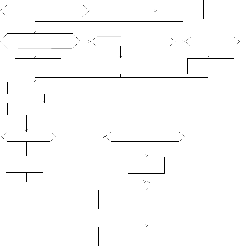
How to use this manual - Flow Chart
The ISP amplifier is designed for OEM applications. It enables the user to
adjust the amplifier for various types of motors and to save valuable adjusting
time in repetitive applications.
Use the following flow chart in order to determine the chapters that you should
read. If you are a new user of the ISP, you should read chapters 1-4 which will
familiarize you with the product.
Read chapter 5.1
Read chapter 6 - Installation
Read chapter 7.1 - Start-Up
Read chapters
1,2,3,4
Familiar with the ISP ? no
no
Read
7.3
Brush Tacho ?
Read
7.2
Read chapter 8 - Adjustments
Read chapter 9 - Summaries
no
Panel (H) version or Rack (R)
Terminals
Read chapters 5.1+5.2
Terminals
Armature voltage feedback ? no
(Current mode)
w/o Elmo mother board ? Rack (R) with Elmo mother board? no Elmo enclosure ?
Read chapter 5.3
Terminals
4
ISP - Rev 6/95
TABLE OF CONTENTS
1. Description ................................ ........................ 6
2. Type Designation ................................ ................... 7
3. Technical specifications ................................ ...........7
4. Operation of the servo control ................................ .....8
4.1 Inputs................................ ....................... 8
4.2 Velocity mode................................ ................ 9
4.2.1 Velocity control using armature voltage feedback .....10
4.3 Current mode................................ ................. 10
4.4 Current loop................................ ................. 11
4.5 Current limits................................ ............... 11
4.5.1 Time dependent peak current limit .................... 11
4.5.2 Dynamic contouring of continuous and peak current limits 12
4.6 Operation of the shunt regulator ............................. 13
4.7 Protective functions ................................ .........14
4.7.1 Short circuit protection ............................. 14
4.7.2 Under/over voltage protection ........................ 14
4.7.3 Temperature protection ............................... 14
4.7.4 Insufficient load inductance ......................... 14
4.7.5 Loss of velocity feedback signal ..................... 14
4.7.6 Shunt regulator duty cycle ........................... 14
5. Terminal Description ................................ ............... 17
5.1 Terminals for Horizontal and Rack mounting versions ..........17
5.2 Mother Board terminals ................................ .......20
5.3 Terminals for ISP mounted in 3U size ENC. .................... 22
6. Installation procedures ................................ ............26
6.1 Mounting................................ ..................... 26
6.2 Wiring................................ ....................... 26
6.3 Load inductance................................ .............. 27
6.4 AC power supply................................ .............. 27
6.5 Wiring diagrams................................ .............. 28
7. Start - Up Procedures ................................ ..............33
7.1 Common procedures for all amplifiers types ................... 33
7.1.1 Inhibit and CW/CCW logic ............................. 33
7.1.2 Velocity mode ................................ ........36
7.1.3 Current mode ................................ .........36
5
ISP - Rev 6/95
7.1.4 Activating the loss of tacho protection (velocity mode only)
................................ ........................... 37
7.1.5 Latch mode of the protective functions .............. 38
7.1.6 Activating the dynamic contouring of the current limits 38
7.2 Velocity control using tachogenerator feedback .............. 38
7.3 Velocity control using armature voltage feedback ............ 39
8. Amplifier adjustment and diagnostics ............................... 40
8.1 Balance adjustment ................................ .......... 40
8.2 Current limit adjustment ................................ .... 40
8.3 Adjusting the motor speed (velocity mode only) .............. 41
8.4 Adjustment of the IxR compensation .......................... 41
8.5 Response adjustment (velocity mode only) .................... 42
9. Tables and Summaries ................................ ............... 44
9.1 Adjusting trimmers ................................ .......... 44
9.2 LED diagnostics ................................ ............. 44
Appendix A - Response adjustment - current loop ........................ 45
Appendix B - Current limits contour adjustment ......................... 47
List of ELMO Service Centers ................................ ........... 77

6
ISP - Rev 6/95
1. Description
The ISP is an amplifier/power supply package, assembled on a single heatsink
with a Eurocard size. The rated output is up to 1500W.
The integrated power supply includes a shunt regulator.
The ISP is available in either panel version or rack version with a 32 poles
DIN 41612 connector.
Standard features
* Zero deadband.
* Excellent linearity.
* 2 inputs.
* Differential input.
* Motor current monitor.
* Inhibit/fault indication (free contact relay).
* Remote control functions: Inhibit and CW/CCW disable.
* Adjustable compensation.
* Adjustable continuous and peak current limits.
* Dynamic contouring of continuous and peak current limits.
* Input balance (offset) adjustment.
* Operation in two velocity modes (Tacho or armature voltage feedback) or current
mode.
* LEDs diagnostics.
* Option - Personality board for ease of replacement: the board includes all the
adjusting trimmers.
Protective functions:
The following protections cause an inhibit which is either self-restart or
latched (for manual reset) selectable by the user:
* Under / over voltage.
* Short circuit: between outputs or each output to ground.
* Low inductance.
* RMS current limit.
* Loss of tacho feedback.
* Over temperature.
* Duty cycle limit of the power supply's shunt regulator.
7
ISP - Rev 6/95
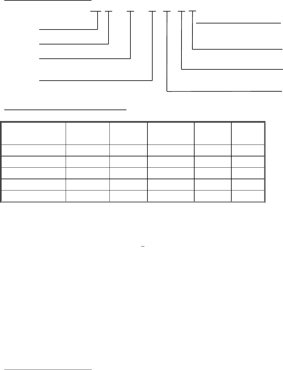
2. Type DesignationISP F - 15 / 65 R W 4
ISP amplifier
Fan cooled 4=40KHz, 6=60KHz
R - Rack mounting
Rated current
20KHz when not specified
PWM switching frequency
H - Panel mounting
Maximum rated voltage for ISP-10/135 only
Additional capacitance
3. Technical specifications
Type AC Supply
*
*
*
Current
limits
Size
Panel types
Size
Rack
Weight
ISP-8/65 14-65 8/16 SP1 3U/8T 0.7
ISP-15/65 14-65 15/30 SP1 3U/8T 0.7
ISP-5/135 80-135 5/10 SP1 3U/8T 0.7
ISPF-10/135_W 28-135 10/20 SP3 3U/12T 0.8
ISP-10/135_W 28-135 10/20 SP4 3U/19T 1.6
* DC output voltage is 130% of AC input voltage.
* 20KHz, 40KHz or 60KHz switching frequency.
* 2KHz current loop response (minimum)
* Outputs voltages of +5V/100mA, +15V/50mA each, for external use.
* Efficiency at rated current - 97%.
* Drift: 10æV/§C (referred to input)
* Operating temperature: 0-50 §C.
* Storage temperature: -10 - +70 §C.
* The W version includes additional 3000 æF in the bus filter.
*
*
* These are the absolute minimum-maximum AC supply voltages under any condition.

8
ISP - Rev 6/95
4. Operation of the servo control
4.1 Inputs
The ISP has 3 inputs: 2 single ended inputs (no.1 at terminal 1 and no.2 at
terminal 5) and one differential input at terminals 3,4.
The current gain of inputs 1 and 2 (current mode) is given by:
8 x Ic x Ki
Gc = --------------- (A/V)
15 + Ri
Ic - amplifier rated continuous current.
Ri - input resistor in Kohm.
R1 for input 1
R2 for input 2
Ki - position of wiper of trimming potentiometer
Ki=0.33 when trimmer is fully CW.
Ki=1 when trimmer is fully CW.
The current gain of the differential input for R3=R4 (current mode) is given
by:
5.33 x Ic
Gcd = ------------- (A/V)
R3
R3 in Kohm
The current gain of the single ended inputs in velocity mode is given by (place
the appropriate Gc for each input):
400 x Ic x Ki
Gv = ----------------- (A/V)
(15+Ri)xR6
Ri,R6 in Kohm

9
ISP - Rev 6/95
The current gain of the differential input in velocity mode is given by:
266 x Ic
Gvd = ---------------- (A/V)
R3 x R6
R3,R6 in Kohm
The maximum input voltage at terminals 1 or 5 is calculated by:
Vinmax = 10 + 0.6Ri (Volts)
Ri in Kohm
The maximum input voltage at terminals 3,4 is calculated by:
Vdmax = 10 + R3 (Volts),
R3=R4 in Kohm
4.2 Velocity mode
In this mode op amp U1/A is employed as a high gain error amplifier The
amplifier sums velocity command and the tachogenerator feedback signal, and
provides the necessary servo compensation and gain adjustments, resulting in
stable, optimum servo operation.
This op amp is configured with two feedback paths:
One, in the form of a resistive T network, controls the DC gain of this
amplifier. The equivalent value of a T network is given by:
1010
Rf= --------
R6
Resistor R6 is mounted in solderless terminals so it can be changed easily
whenever the DC gain of the error amplifier is to be changed. The AC gain is
controlled by C1, R5 and COMP trimmer. Maximum AC gain is obtained with COMP
trimmer set fully CW. Setting COMP trimmer fully CCW removes AC gain and no lag
in response occurs. R5 and C1 are mounted in solderless terminals and can be

10
ISP - Rev 6/95
easily replaced in cases when COMP trimmer range is not enough to get optimum
result.
The output of the error amplifier is:
1 + SxC1xR5
Vo = (V1Gv1 + V2Gv2) x [ --------------------------- ]
1 + SxC1xR5(1 + RfxKi/R5)
V1,V2, - Input signals
Gv1,Gv2 - Gain of inputs.
Ki = Position factor of the wiper of COMP trimmer.
Full CW = 0.1
Full CCW = 1
The feedback element must be connected for negative feedback.
The polarity of the ISP servo amplifiers is such that a positive input signal
results in a negative voltage at terminal M1 with respect to terminal M2.
4.2.1 Velocity control using armature voltage feedback
By inserting R8 to its solderless terminals, the armature voltage is fed into
the error amplifier to be used as a velocity feedback. This feature is useful for
all cases when low regulation ratio and low speed accuracy are acceptable.
4.3 Current mode
In order to operate the servo amplifier as a current amplifier, the velocity
loop should be disabled. This is done by converting the error amplifier into a
low gain DC amplifier which has a flat response beyond the desired current
bandwidth. In this mode, R6 and C1 have to be removed from the circuit.

11
ISP - Rev 6/95
4.4 Current loop
Current loop control is obtained by op amp U1/B (Current amplifier) and R7, C2
which form a lag-lead network for current loop. The standard amp is equipped with
R7 (100Kohm) and C2 (0.01æF) to get optimum current response for an average motor
in this power range. These components are mounted in solderless terminals.
4.5 Current limits
The servo amplifier can operate in the following voltage-current plane:
-Ip -Ic
+V
Ic Ip
Intermittent
zone
Continuous
zone -V
Ic - Continuous current Ip - Peak current
Fig. 4.1: Voltage-Current plane
Each amplifier is factory calibrated to have this shape of voltage-current
operating area with rated values of continuous and peak current limits. In
addition the peak current limit is time dependent as explained in 4.5.1.
4.5.1 Time dependent peak current limit
The peak current is so designed that its duration is a function of the peak
amplitude and the motor actual operating current before the peak demand. The
maximum peak current is available for 1.6 second. The duration of Ip is given by:
12
ISP - Rev 6/95
Ip - Iop
Tp = 2.2ln ----------
Ip - Ic
Ic - Amplifier continuous current rating.
Ip - Peak demanded (not amplifier Ip)
Iop - Actual operating current before the peak demand.
Example:
A motor is driven by an ISP-15/65 amplifier at constant speed and constant
current of 5A. What is the maximum possible duration of a 20A peak ?
20 - 5
Tp = 2.2ln -------- = 2.42 seconds
20 - 15
4.5.2 Dynamic contouring of continuous and peak current limits
Most of the servo motors have reduced continuous current limits at high speeds
(Fig. 4.2). This phenomenon is due to commutation limits and iron looses which
become significantly high as speed increases and this leads to reduction of the
continuous current limit. The ISP amplifiers have the features which enable the
user to define the current limit envelope as closely as possible to the motor
operating envelope defined by the motor manufacturer.
Velocity
Torque
Cont.
zone Interm.
zone
Fig. 4.2:
Typical operating envelope of a brush servo motor

13
ISP - Rev 6/95
4.6 Operation of the shunt regulator
A shunt regulator is included in the power supply section of the ISP. The shunt
regulator is a switching type, wherein dissipative elements (resistors) are
switched across the DC bus, whenever the voltage reaches a predetermined level.
The function of the shunt regulator is to regulate the voltage of the DC bus
during the period of motor deceleration, when there is a net energy outflow from
the motor to the amplifier. The amplifier handles this reverse energy just as
efficiently as it provides energy to the motor, hence, most of the energy is
passed through the amplifier to the power supply, where the returning energy
charges the filter capacitors above their normal voltage level, as determined by
the AC incoming voltage.
When the capacitors charge-up reaches the predetermined voltage level (Vr), the
shunt regulator begins its regulating action. The bus is regulated to this range
until regeneration ceases.
On multi-axis systems, it is recommended to parallel the DC bus of all the
ISPs.
SHUNT specifications
Type Reg. Voltage (Vr) Reg. Current (A)
ISP-8/65 91 11
ISP-15/65 91 22
ISP-5/135 191 6
ISPF-10/135_W 191 12
ISP-10/135_W 191 12
14
ISP - Rev 6/95
4.7 Protective functions
All the protective functions (excluding 4.7.6) activate internal inhibit. There
are two modes of resetting the amplifier after the cause of the inhibit
disappears: Self Restart and Latch.
- Self restart: The amplifier is inhibited only for the period that the inhibit
cause is present.
- Latch: All failures latch the inhibit and only a reset signal will clear the
latch.
4.7.1 Short circuit protection
This protection is realized by sensing current in the DC line. Every current
peak above a certain value will inhibit the amplifier for a period of approx.
30mS (if in restart mode).
The amplifier is protected against shorts between outputs and either output to
ground.
4.7.2 Under/over voltage protection
Whenever the DC bus voltage is under or over the limits indicated in the
technical specifications, the amplifiers will be inhibited.
4.7.3 Temperature protection
Temperature sensor is mounted on the heatsink. If, for any reason, the
temperature exceeds 85§C the amplifier will be inhibited. The amplifier will
restart when the temperature drops below 80 §C.
4.7.4 Insufficient load inductance
Whenever the load inductance is too small, the current spikes will be very
high. In such cases the amplifier will be disabled.
4.7.5 Loss of velocity feedback signal
If the amplifier loses the velocity feedback signal it will inhibit itself. In
the "Self Restart" mode it will restart after a delay of 6-8 seconds.
4.7.6 Shunt regulator duty cycle
Whenever the ratio between "ON" time to "OFF" time of the shunt exceeds 5-10%
the shunt will be inhibited.
15
ISP - Rev 6/95
T4
10K
100
C1
.022MF
1000PF
R5
475K
100K
4700PF T7
10K
R1
INPUT 1
CURRENT COMMAND MONITOR.
15
1
2
3R3 100K
5.11K
.01MF
10K
-
100K
+
-
R6
100K
10K
R7
100K
100PF
+
-
C2
.01MF
PWM
TO POWER
STAGE
CONVERTER
CURRNET
FEEDBACK
A
10K
T3
IP
CURRENT
LIMITS
T2
IC
+
R2
INPUT 2
10K
.01MF
R4
4
5
CURRENT
T6
10K
.1MF
5.11K
+V
T5
10K
100K
-V
offset
4.7M
R8 AVOLTAGE
ARMATURE
CONTOURS
CURRENT
R9
R10
R11
MONITOR
RELAY
7
17
18
16
8CW
BACK EMF OUTPUT
R19a PROTECTIONS
inhibit latch
R12
R13
A
FROM POWER STAGE
D17
loss of tacho
loss of tacho
loss of tacho
R16
R15
R14
5V
5.11K
100 +
R20a
INHIBIT
INPUT
CCW
R18
9
10
12
+5V
11 13
-
2.8V
-15V
14
+15V
RESET
6

16
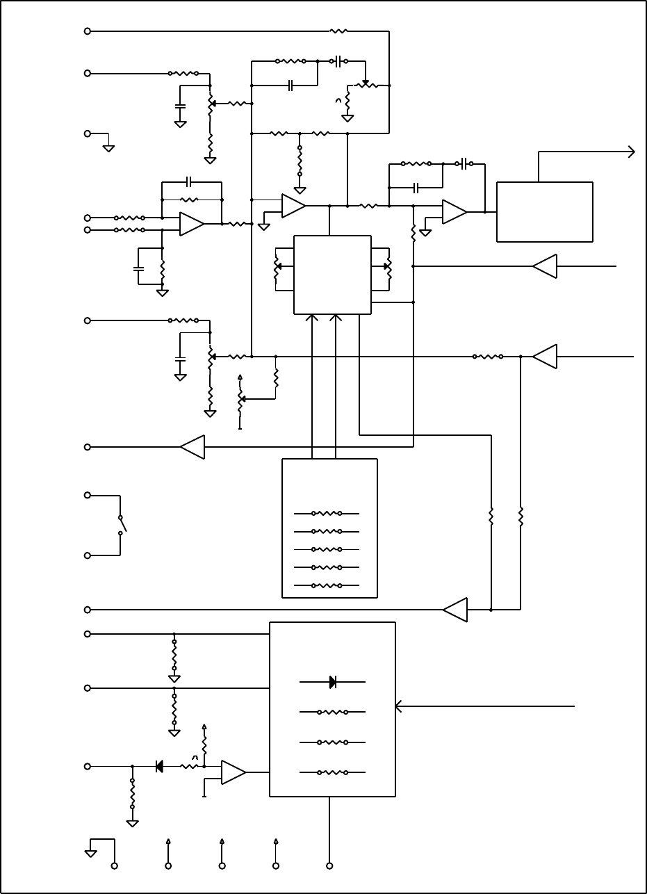
ISP - Rev 6/95
U1
T2 T3 T4
COMPIPIC
U5
T6 T7
GAIN 1GAIN 2
T5
OFFSET
R1
R2 U12
L1 L2 L3
ICINH
VS
L4
SO
J1
12
13
14
1
2
3
4
5
6
7
8
9
10
11
U17
R3
R4
R5
R6
R7
R8
R9
U14
U15
R10
R11
R12
R13
R14
U7
U6
U2
U3
U4
U13
R15
R16
R18
C1
C2
U10
U9
U8
D17
U16
U11 U18
J3
U19
R19A
R20A 3
4
5
6
7
8
9
10
11
12
13
14
1
2
ISP - CONTROL BOARD

17
ISP - Rev 6/95
5. Terminal Description
5.1 Terminals for Horizontal and Rack mounting versions
Power stage
H R Function Remark
AC 2ac,4c AC input All pins are shorted on the PCB.
M1 8ac,10a Armature
output
This output will be negative when a positive signal
is fed to one of the inputs. All pins are shorted on
the PCB.
M2 6ac,4a Armature
output
This output will be positive when a positive signal
is fed to one of the inputs. All pins are shorted on
the PCB.
AC 12ac,10c AC input All pins are shorted on the PCB.
Control stage
H R Function Remark
1 32a Input 1 For more details see 4.1.
2 32c Circuit common
3 30a Negative
differential
input
For more details see 4.1.
4 30c Positive
differential
input
For more details see 4.1.
5 28a Input 2 For more details see 4.1.
6 28c Reset for latch
mode
low level input voltage *
*
* enables the amplifier
(see 7.1.5).
7 26a Current monitor Ic
Scale is = ------ (A/V)
3.75
8 26c CW disable Two modes - see chapter 7.1.1 *
*
*
*
*
* -1V < Vil < 1V ; 2V < Vih < 30V
Source sink capability - 2mA.

18
ISP - Rev 6/95
Control stage - Cont.
H R Function Remark
9 24a CCW disable Two modes - see chapter 7.1.1 *
*
*
10 24c Inhibit input Two modes - see chapter 7.1.1 *
11 22a Circuit common
12 22c +5V 100mA
13 20a -15V + 5%, 50mA external load.
14 20c +15V + 5%, 50mA external load.
15 18a Current command
monitor
Ic
Scale is = ------ (A/V)
3.75
16 18c Back EMF output See Appendix B.
17,
18
16a,
16c
Inhibit output A potential free relay contact. Closed when
amplifier is enabled.
Contact rating: 0.5A, 200V, 10W
19 14a DC power voltage
output - common
5A max.
20 14c DC power voltage
output - positive
5A max.
Remark: In the following paragraphs the terminals will be related to all the
mounting types as in the the following example:
H-18,R-16c,E-J1/8.
*
*
* -1V < Vil < 1V ; 2V < Vih < 30V
Source sink capability - 2mA.

19
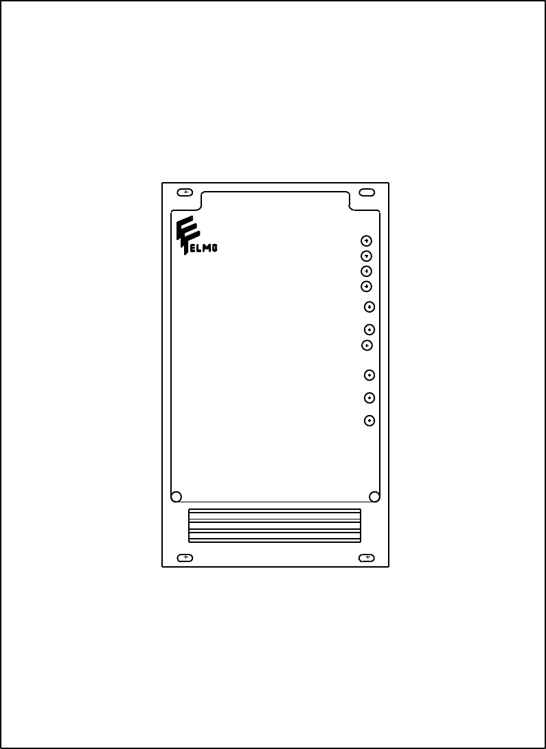
ISP - Rev 6/95
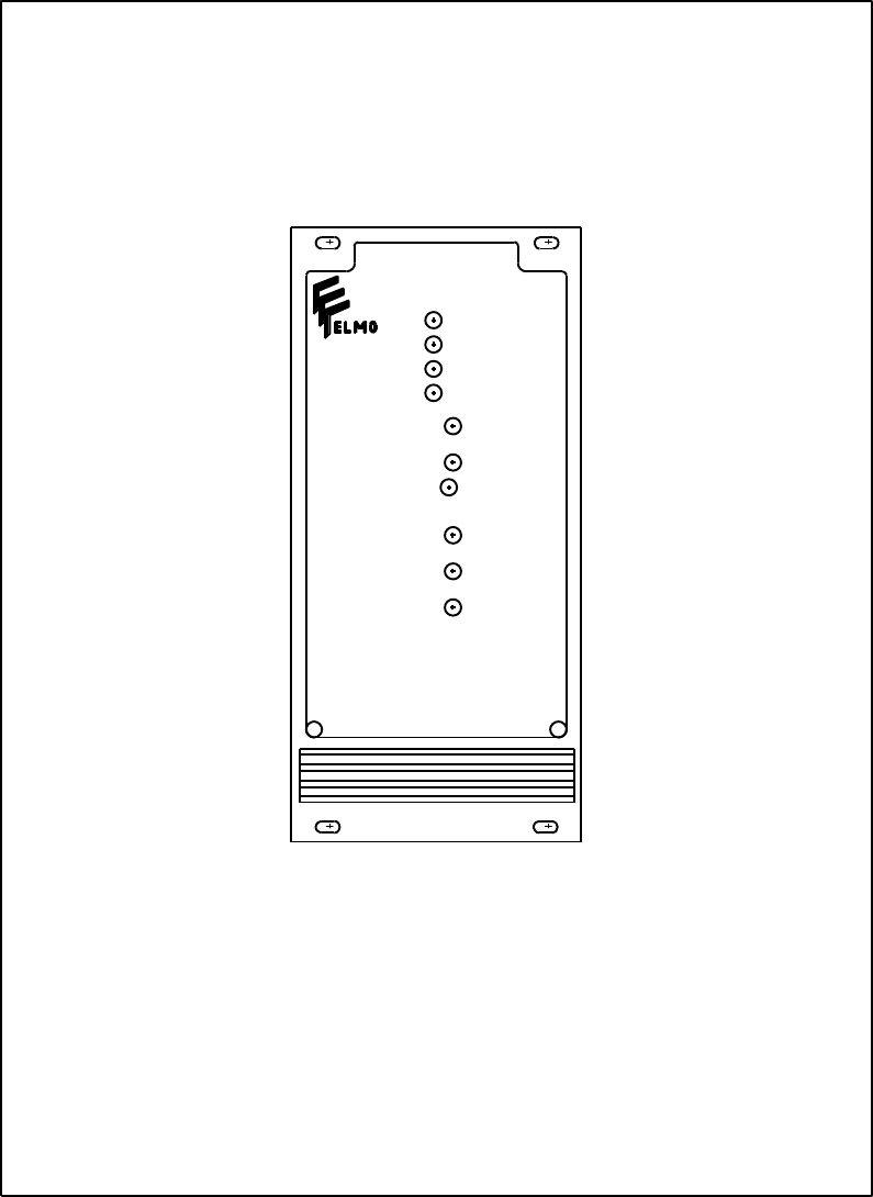
TERMINALS OF ISP - PANEL VERSION
AC M2 M1 AC
120

20
ISP - Rev 6/95
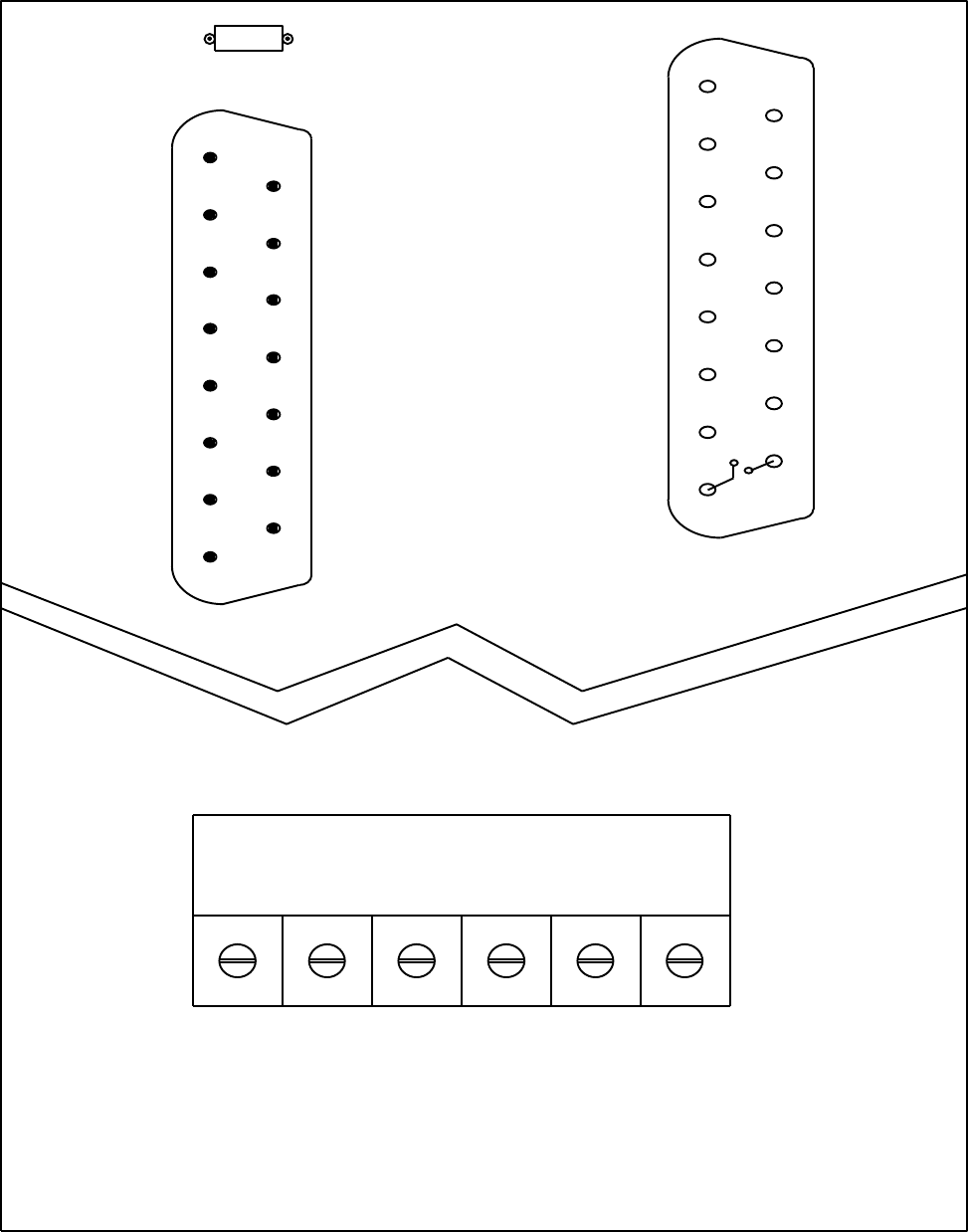
5.2 Mother Board terminals
The MBA-ISP/N is designed for 19" rack systems. It has screw type terminals for
both power and signals with identical designations as in the panel versions
except for the following new terminals:
21 Potential free Inhibit Input (+). See 7.1.1.
22 Potential free Inhibit Input (-). See 7.1.1.
The Potential Free Inhibit Input is applicable only when the "inverted inhibit
logic" is used (R18 in the amplifier is inserted). An opto-Coupler (IL5) is used
to isolate between the Inhibit signal and the amplifier circuit. Activating this
opto-coupler is done by inserting R1 on the mother board according to the
following relation:
R1 = 100 x Vinh (ohm)
Vinh - voltage in the inhibit input.
Standard value is 2.4K (For 24 volts) Source must be capable of source or sink
10mA.

21
ISP - Rev 6/95
R1
22
21
18
17
16
AC1
M2
AC1
15
14
13
12
11
10
M1
AC2
AC2
VS
VS
9
8
7
6
5
4
G
G
U1
3
2
1
MBA-ISP/N

22
ISP - Rev 6/95
5.3 Terminals for ISP mounted in 3U size ENC.
The MBA-ISP/3UE is designed for Elmo enclosures. It has screw type terminals
for the power and D-type connectors for the signals.
The Potential Free Inhibit Input is applicable only when the "inverted inhibit
logic" is used (R18 in the amplifier is inserted). An opto-Coupler (IL5) is used
to isolate between the Inhibit signal and the amplifier circuit. Activating this
opto-coupler is done by inserting R1 on the mother board according to the
following relation:
R1 = 100 x Vinh (ohm)
Vinh - voltage in the inhibit input.
Standard value is 2.4K (For 24 volts) Source must be capable of source or sink
10mA.
Power Terminals
Terminal Function Remark
AC AC input
M1 Armature
output
This output will be negative when a positive signal
is fed to one of the inputs.
M2 Armature
output
This output will be positive when a positive signal
is fed to one of the inputs.
AC AC input
GND Ground

23
ISP - Rev 6/95
Control connector - J1
Pin Function Remark
1 Input 2 For more details see 4.1.
2 Back EMF output See Appendix B.
3 Input 1 For more details see 4.1.
4 Negative
differential
input
For more details see 4.1.
5 Positive
differential
input
For more details see 4.1.
6 Current monitor Ic
Scale is = ------ (A/V)
3.75
7Current command
monitor
Ic
Scale is = ------ (A/V)
3.75
8,15 Inhibit output A potential free relay contact. Closed when
amplifier is enabled.
Contact rating: 0.5A, 200V, 10W
9,10 Circuit common
11 +15V + 5%, 50mA external load.
12 -15V + 5%, 50mA external load.
13 +5V 100mA
14 Circuit common

24
ISP - Rev 6/95
Control connector - J2
Pin Function Remark
1 Inhibit input Potential free inhibit input (-).
See 7.1.1 *
2 Inhibit input Potential free inhibit input (+).
See 7.1.1 *
3 Inhibit input Two modes - see chapter 7.1.1 *
4 CCW disable Two modes - see chapter 7.1.1 *
5 CW disable Two modes - see chapter 7.1.1 *
6Reset for latch
mode
low level input voltage *
*
* enables the amplifier
(see 7.1.5).
7 Back EMF output See Appendix B.
8 Input 2 For more details see 4.1.
9 -15V + 5%, 50mA external load.
10 +15V + 5%, 50mA external load.
11,12 Circuit common
13 +5V 100mA
14,15 Circuit common
Remark: In the following paragraphs the terminals will be related to all the
mounting types as in the the following example:
H-18,R-16c,E-J1/8.
*
*
* -1V < Vil < 1V ; 2V < Vih < 30V
Source sink capability - 2mA.
25
ISP - Rev 6/95
R1
J1
FEMALE
J2
MALE
GNDAC GNDM1M2AC
MBA - ISP/3UE
9
COM.
1
IN 2
BACK
2
3
4
IN 1
DIFF(-)
EMF
10
11
12
COM.
+15V
-15V
13
14
15
+5V
COM.
RELAY
5
6
7
DIFF(+)
CURRENT
MONITOR
CURRENT
COMMAND
8
8
7
6
IN 2
RESET
BACK
EMF 15
14
COM.
COM.
13
12
11
+5V
COM.
COM.
+15V
5
4
3
C.W
C.C.W
INH.
2
1
INH.(+)
INH.(-)
10
9
-15V

26
ISP - Rev 6/95
6. Installation procedures
6.1 Mounting
The ISP series dissipates its heat by natural convection. For optimum
dissipation the amplifier should be mounted with the fins vertical.
6.2 Wiring
Proper wiring, grounding and shielding techniques are important in obtaining
proper servo operation and performance. Incorrect wiring, grounding or shielding
can cause erratic servo performance or even a
complete lack of operation.
a) Keep motor wires as far as possible from the signal level wiring (feedback
signals, control signals, etc.).
b) If additional inductors (chokes) are required, keep the wires between the
amplifier and the chokes as short as possible.
c) Minimize lead lengths as much as is practical.
d) Use twisted and shielded wires for connecting all signals (command and
feedback). Avoid running these wires in close proximity to power leads or
other sources of EMI noise.
e) Use a 4 wires twisted and shielded cable for the motor connection.
f) Shield must be connected at one end only to avoid ground loops.
g) All grounded components should be tied together at a single point (star
connection). This point should then be tied with a single conductor to an
earth ground point.
h) After wiring is completed, carefully inspect all conditions to ensure
tightness, good solder joints etc.
A reliable connection with the spring type connectors is achieved with wires of 0.5mm 2
(AWG 20) stripped to a length of 11mm (.043").

27
ISP - Rev 6/95
6.3 Load inductance
The total load inductance must be sufficient to keep the current ripple within
the 50% limit (10-20% of rated current is recommended). The armature current
ripple (Ir) can be calculated by using the following equation:
0.5 x Vs
Ir = ---------- (A)
f x L
L - load inductance in mH.
Vs - Voltage of the DC supply in Volts.
f - Switching frequency in KHz.
If motor inductance does not exceed this value, a choke should be added (on the
motor branch) summing together the required inductance
Lch = L - Larm
Lch - Choke inductance
Larm - Armature inductance
6.4 AC power supply
AC power supply can be at any voltage in the range defined within the technical
specifications (chapter 3). However, if the power source to the power supply is
the AC line (through a transformer), safety margins have to be considered to
avoid activating the under/over voltage protection due to line variations and/or
voltage drop under load.
The nominal DC bus voltage should be in the following range:
1.2Vdcmin < Vdc < 0.9Vdcmax
Vdcmin - Minimum DC bus in the table of chapter 3
Vdcmax - Maximum DC bus in the table of chapter 3
28
ISP - Rev 6/95
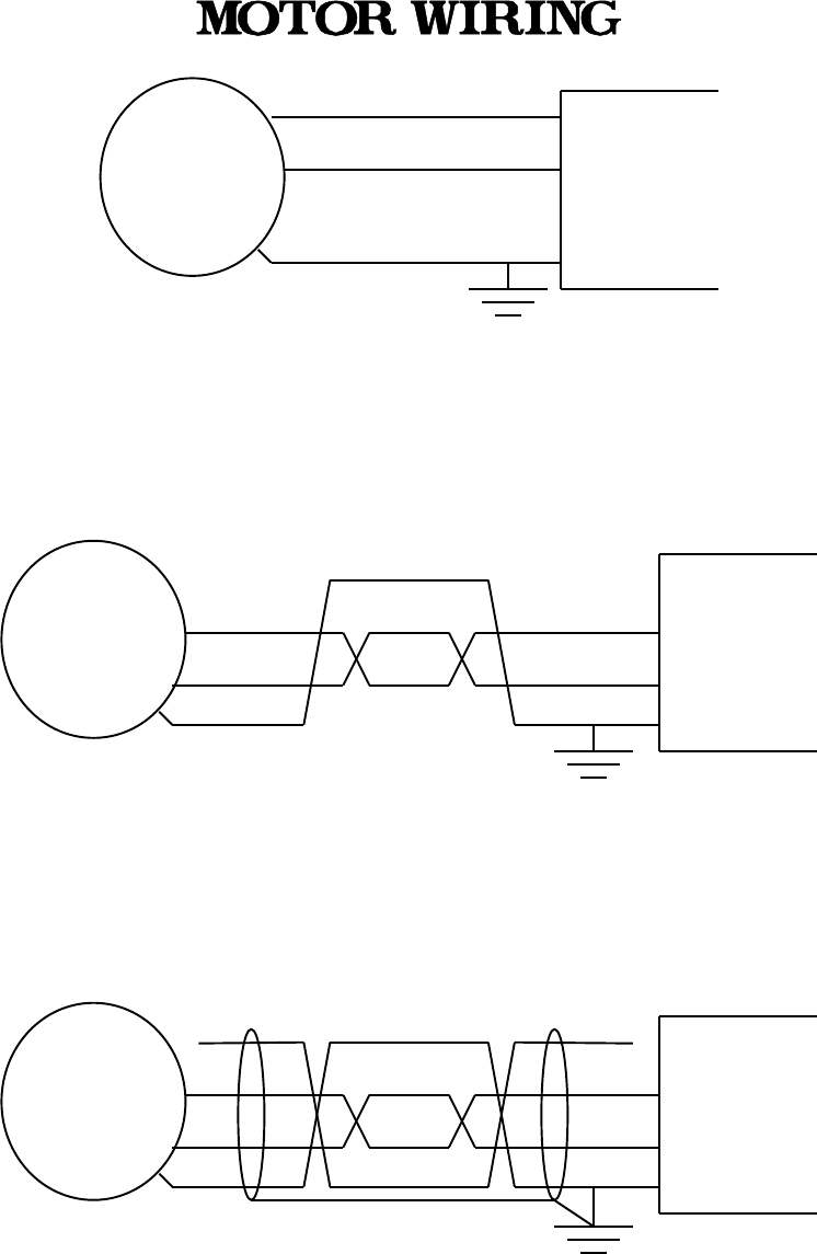
6.5 Wiring diagrams
Motor
A
B
GND
Chassis
ISP
M1
M2
Minimum acceptance
=============================================================
Motor A
B
GND
Chassis
Power wires twisted together
ISP
M1
M2
Acceptable for most applications
============================================================
Motor A
B
GND
Chassis
Power wires twisted and shielded
ISP
M1
M2
Optimum wiring, minimum RFI
29
ISP - Rev 6/95
DC power common is internally
connected to control common
Heatsink
Isolating transformer
ISP
+Vs
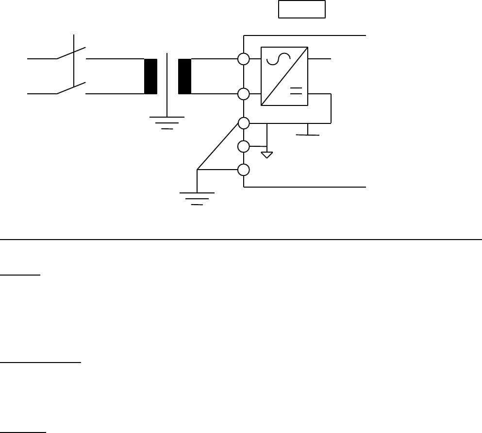
Guide lines for connecting a non isolated amplifier with an isolating power transformer
Ground:
DC power common
Motor chassis
Amplifier's heat sink
Do not ground:
Control common - It is internally connected to the power common. Grounding the control
common will create a ground loop.
Caution:
- If source of motor command is grounded, use amplifier's differential input.
Otherwise, ground loop is created.

30
ISP - Rev 6/95
AC
AC
+Vs
DC power common
Control common
Heatsink
AC
AC
+Vs
DC power common
Control common
Heatsink
To additional
ISPs
CONNECTING MORE THAN ONE ISP
SINGLE PHASE TRANSFORMER
ISP
ISP
31
ISP - Rev 6/95
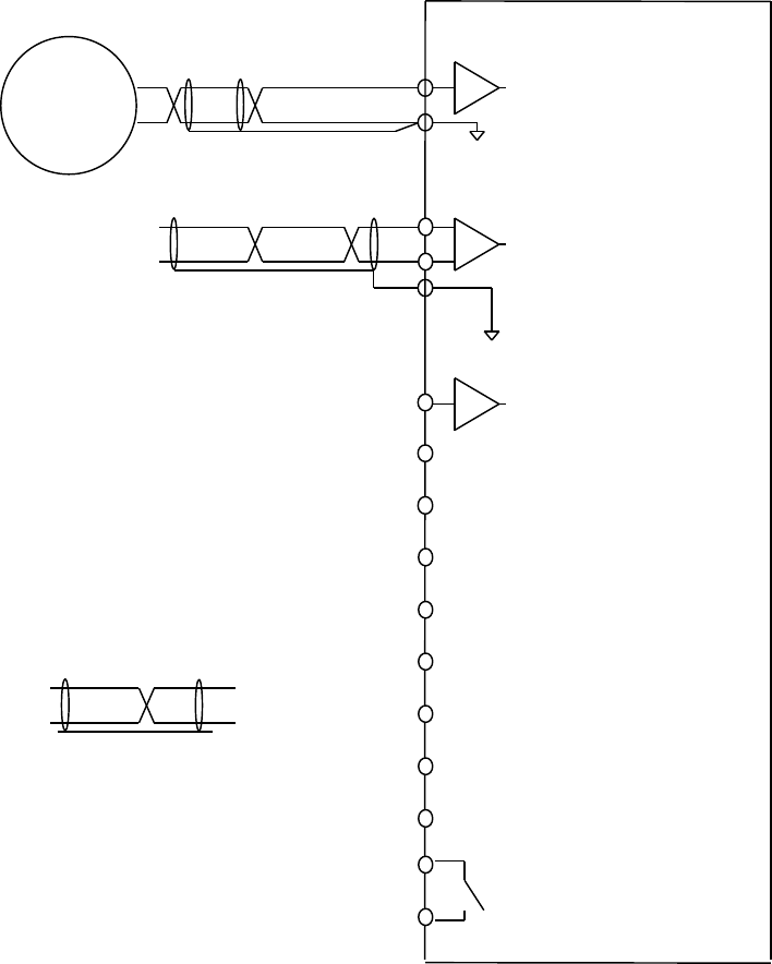
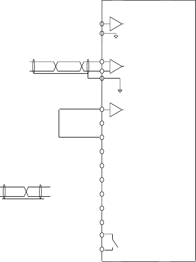
ISP CONTROL CONNECTIONS
TACHOGENERATOR FEEDBACK
Reset
Motor command
A
-15V
CW disable
Twisted and shielded pair
1
3
+
_
4
14
13
+15V
12 +5V
7Current monitor
10
5
11
2
8
Tacho
6
9
Inhibit input
CCW disable
A
Relay
18
17
32
ISP - Rev 6/95
ISP CONTROL CONNECTIONS
ARMATURE VOLTAGE FEEDBACK
Reset
Motor command
A
-15V
CW disable
Twisted and shielded pair
1
3
+
_
4
14
13
+15V
12 +5V
7Current monitor
10
5
11
2
8
6
9
Inhibit input
CCW disable
A
Relay
18
17
33
ISP - Rev 6/95
7. Start - Up Procedures
All the operations of this chapter do not require power on the unit. The steps of
paragraph 7.1 must be performed before proceeding to the appropriate feedback sensor
section.
7.1 Common procedures for all amplifiers types
7.1.1 Inhibit and CW/CCW logic
Select the desired Inhibit and CW/CCW logic you need:
a) Disable by Low
Inhibit/CW/CCW functions will be activated by connecting their inputs to a low
level signal. If no signal is applied to these inputs the amplifier will be
enabled upon power on.
For this logic, R18 (for Inhibit), R19a (for CW), R20a (for CCW) should not be
installed.
+5V
ISP DISABLED BY ACTIVE LOW OR CLOSED CONTACT
C
-1V < Vil < 1V
2V < Vih < 30V

34
ISP - Rev 6/95
b) Enable by High
Inhibit/CW/CCW functions will be de-activated by connecting their inputs to a
high level signal. If no signal is applied to these inputs the amplifier will be
disabled upon power on.
For this logic insert 3.6Kohm ( +10%)resistors for R18 (Inhibit), R19a (CW),
R20a (CCW). The power of these resistors is calculated according to:
Pmin=V2/1500 (Watt)
+5V
ISP ENABLED BY ACTIVE HIGH OR CLOSED CONTACT
C
+v
+5V
C
+5V
C
R18INHIBIT
R19aCW
R20aCCW
2V < +V < 30V

35
ISP - Rev 6/95
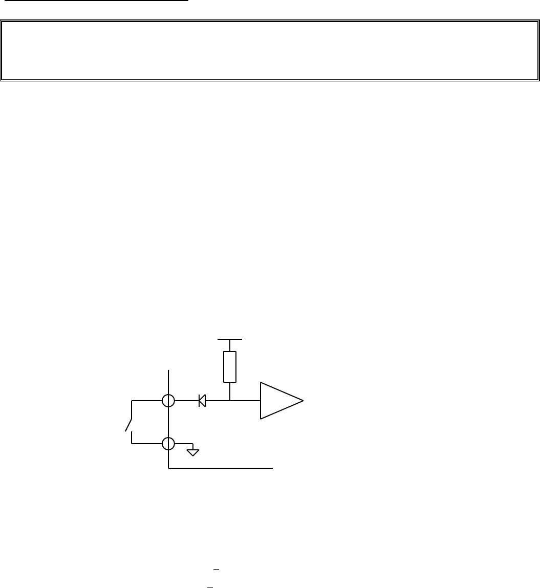
OPTO-ISOLATED INHIBIT
+5V
ISP ENABLED BY ACTIVE LOW OR CLOSED CONTACT
C
R18
V +5
R1
MBA-ISP/... ISP CONTROL BOARD
Inhibit
+5V
ISP ENABLED BY ACTIVE HIGH OR CLOSED CONTACT
C
R18
+5
R1
MBA-ISP/... ISP CONTROL BOARD
Inhibit
V
R1 = 100 x V (ohm)
V - Voltage at the inhibit input.
Standard value is 2.4K (for 24V). Source must be capable to source or sink 10mA.
36
ISP - Rev 6/95
7.1.2 Velocity mode
To operate in velocity mode the velocity loop should be enabled by converting
the error amplifier to a high gain PI amplifier.
Make sure that: R6 (30ohm), R5 (475Kohm) and C1 (0.022 æF), in solderless
terminals, are installed on the board.
7.1.3 Current mode
a) Converting the amplifier into current mode
To operate in current mode the velocity loop should be disabled by converting
the error amplifier to a low gain proportional amplifier.
- Remove R6 (in solderless terminals).
- Remove C1 (in solderless terminals).
In addition, you must make sure that the velocity feedback signal is not
entering the error amplifier. If a tachogenerator is used, make sure that it is
not connected to the amplifier.
b) Selecting the reference signal gain
The ISP has 2 single ended inputs (terminals H-1,R-32a,E-J1/3 and H-5,R-28a,E-
J1/1) and a differential input (terminals H-3,R-30a,E-J1/4, and H-4,R-30c,E-
J1/5).
The standard procedure recommends to use the differential input for the
reference signal.
Following are the input maximum voltage and impedance with the standard values
of input resistors:
INPUT - RESISTOR STANDARD
VALUE
MAX.
VOLTAGE
Current Gain(A/V)
(in current mode)
INPUT
IMPEDANCE
Input 1 - R1 2.49Kohm 11V 0.46xIc 17.5 Kohm
Input 2 - R2 15Kohm 19V 0.27xIc 30Kohm
Differential - R3,4 20Kohm 30V 0.27xIc 30 Kohm
See chapter 4.1 for calculation of other values

37
ISP - Rev 6/95
7.1.4 Activating the loss of tacho protection (velocity mode only)
Activating the loss of tacho protection is done by installing R14 (different
value for 65V or 135V amplifiers),R15, and R16 as follows:
1530
R14(65V) = ------- (Kohm)
Vam
2730
R14(135V) = ------ (Kohm)
Vam
100 x Vam
R15 = ----------- (Kohm)
Ip x Rm
R16 < 10 ohm
Vam - Armature voltage at maximum application speed.
Ip - Amplifiers' rated peak current limit.
Rm - Total ohmic resistance of motor.
R9 should be calculated and inserted according to the tacho voltage at maximum
application velocity (Vtm):
For Vtm > 7.5V:
insert R9 = 301Kohm.
For Vtm < 7.5V:
2250
R9 = ------- (Kohm)
Vtm

38
ISP - Rev 6/95
7.1.5 Latch mode of the protective functions
Self Restart(D17 removed): The amplifier is inhibited only for the period that
the inhibit cause is present.
Latch (D17 - inserted): Failures 4.7.1-5 latch the Inhibit and the diagnostic
LED. For restart (after clearing the failure source), reset has to be performed
by connecting the reset input to the circuit common.
7.1.6 Activating the dynamic contouring of the current limits
If you do not use this feature make sure that R11 and R13 are not installed on
the board.
If you want to activate this function refer to appendix B.
7.2 Velocity control using tachogenerator feedback
When using tacho feedback, it is recommended to use the single ended input no.2
for the tacho signal and to use the differential input for the reference signal
in order to reduce common mode noises.
R2,R3 and R4 are calculated and inserted for two tacho voltage ranges:
For Vtm > 7.5V
R3 = R4 = 1.33xVdm (Kohm)
Vdm - maximum reference voltage at the differential input.
R2 = 2xVtm - 15 (kohm)
Vtm - Voltage generated by the tacho at maximum velocity.
For Vtm < 7.5V
R3 = R4 = 10xVdm/Vtm (Kohm)
Vdm - maximum reference voltage at the differential input.
Vtm - Voltage generated by the tacho at maximum velocity.
R2 = 470 Ohm

39
ISP - Rev 6/95
7.3 Velocity control using armature voltage feedback
The reference signal should be connected to the differential input and R3,R4
should be calculated and inserted according to:
R3 = R4 = 1.33xVdm (Kohm)
Vdm - maximum reference voltage at the differential input.
The armature voltage feedback will enter the error amplifier by inserting R8,
calculated for the two voltage types as follows:
For ISP-X/65:
R8(65V) = 1.3xVam (Kohm)
Vam - armature voltage at maximum application speed
For ISP-X/135:
R8(135V) = 0.73xVam (Kohm)
Vam - armature voltage at maximum application speed
IxR compensation
In order to improve the speed stability in various load conditions, an IxR
compensation is required. This is achieved by:
- Connect the Current Feedback Monitor (terminal H-7,R-26a,E-J1/6) to input 1
(terminal H-1,R-32a,E-J1/3).
- Rotate T7 to max. CCW position (minimum IxR compensation).
- Insert R1 as follows:
3 x Vam
R1 = ---------- (Kohm)
Rm x Ip
Vam - Armature voltage at maximum application speed.
Ip - Amplifiers' rated peak current limit.
Rm - Total ohmic resistance of motor.

40
ISP - Rev 6/95
8. Amplifier adjustment and diagnostics
Important remarks:
A. If all the previous steps were accomplished you may now turn on the power and
continue with the following adjustments. You may omit the step for current mode
or velocity mode according to your application.
B. In some applications, especially those where the motor electrical parameters
(total inductance and resistance in the armature circuit) are much smaller or
larger than normally encountered, the current loop response should be optimized
before proceeding with the following steps - See Appendix A.
8.1 Balance adjustment
If the motor is rotating with the command signal at zero voltage, a balance
adjustment will be necessary. Turn the balance trimmer (T5) as required until the
motor stops. As a rule, have the command signal connected and set to zero when
balancing the amplifier. This way, any offset in the command signal will be
canceled.
8.2 Current limit adjustment
The amplifiers' current limits can be adjusted without the need for loading.
Disconnect motor leads and connect a voltmeter between the Current Command
Monitor (terminal H-15,R-18a,E-J1/7) and the circuit common. Apply maximum input
voltage to one of the inputs to cause an error at the error amplifier (input gain
trimmer should be fully CW). In order to adjust the continuous limit - turn T3
(Ip) fully CCW to disable Ip, then use T2 (Ic) to adjust the continuous limit by
monitoring the meter readout. Full CW rotation of T2 will result in rated current
limit. After adjusting the continuous limit, turn T3 up to the desired peak
level.
The current monitor range is up to 7.5V and its scale depends on the amplifier
rated continuous current (Ic) and is given by:

41
ISP - Rev 6/95
Ic
Current monitor scale (A/V) : ------
3.75
8.3 Adjusting the motor speed (velocity mode only)
Adjusting the speed is done by adjusting the input gain trimmer of the tacho
feedback:
- Increasing/decreasing the feedback gain will decrease/increase the speed.
It is also possible to increase/decrease the command gain (change the fix
resistors of the differential amplifier) in order to increase/decrease the speed.
Best performance is achieved when the feedback gain is as close as possible to
its maximum value. Therefore, the final adjustment should yield with Ki of the
tacho input trimmer over 0.8.
8.4 Adjustment of the IxR compensation
If you do not use this feature, skip this chapter.
After following all the instructions in 7.3, you may improve the speed
stability in various load conditions by performing the following procedure:
a. Run motor at 2/3 of nominal speed.
b. Apply nominal load.
c. Increase IxR compensation (CW rotation of gain 1 - trimmer T7) until motor's
speed reaches the no load speed.
d. Notice that a high compensation may result in unstable operation of the
amplifier.
Reducing the DC and AC gains of the error amplifier by increasing C1 and R5 is
recommended. The final values depend on the type of motor and mechanical load, so
optimum results will be achieved by the empirical method.
42
ISP - Rev 6/95
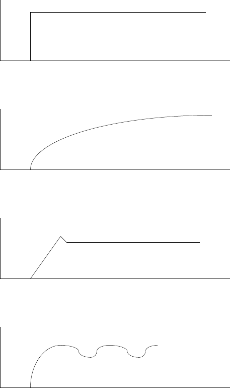
8.5 Response adjustment (velocity mode only)
In most applications optimum response is achieved by adjusting the compensation
(COMP) trimmer. Adjustment procedure is as follows:
- Provide the amplifier with a low frequency, bi-directional square wave velocity
command (A 0.5Hz, ñ2.0V waveform is often employed)
- Apply power to the amplifier, and while monitoring the tachometer signal,
gradually adjust the COMP trimmer from the CCW toward the CW position. Optimum
response (critically-damped) should be achieved at some position before
reaching full CW on T4. Fig 8.1 illustrates the types of waveforms observed
for various setting o T4.
In some applications, especially those where the load inertia is much smaller
or larger than normally encountered, the standard compensation components values
of 0.022æF for C1 and 470Kohm for R5 may not allow an optimum setting of the COMP
trimmer T4. In fact, the velocity loop may be unstable for any setting of T4.
In these cases different values for C1 and R5 must be chosen. The following
procedure can be used to select these values:
- Short circuit C1 with a short jumper wire.
- Replace R5 with a decade resistance box. Initially set the box resistance at
20Kohm.
- Set T4, the COMP trimmer to approximately midrange.
- Input a 0.5Hz, ñ2V bi-directional square wave velocity command signal to the
amplifier.
- Apply power, and while monitoring the tachometer signal, gradually increase the
value of the box resistance until optimum response a depicted in Fig 8.1 is
achieved.
- Substitute the closest standard value discrete resistor for R6 and
remove the decade resistance box.
- Remove the shorting jumper across C1, and again check the response using the
squarewave test signal. If near optimum result are obtained, trim the response
using the COMP trimmer T4 for the optimum.

43
ISP - Rev 6/95
- If the previous step does not yield satisfactory results, if unacceptable
overshooting has been noted, substitute a larger value than 0.022æF; or, if
the response is overdamped substitute a smaller value than 0.022æF.
Repetition of this procedure should yield an optimum choice for C1.
Reference input signal
Overdamped: T4 too far CW
Critically damped: T4 optimum
Underdamped: T4 too far CCW
Fig. 8.1
Typical velocity response waveforms

44
ISP - Rev 6/95
9. Tables and Summaries
9.1 Adjusting trimmers
Six trimmers are installed on the ISP board with the following functions:
T7 (Gain 1) - CW rotation increases input 1 gain.
T6 (Gain 2) - CW rotation increases input 2 gain.
T5 (Balance) - see 8.1.
T4 (compensation) - See 8.6.
T3 (Ip) - CW rotation increases peak current limit (see 8.2).
T2 (Ic) - CW rotation increases continuous current limit (see 8.2)
9.2 LED diagnostics
Four LEDs are installed on the ISP with the following designations: Ic, In, Vs,
SO. Under normal operation only Vs should illuminate (Vs indicates the existence
of supply voltages). The following table represents the faults indications of the
LEDs:
1 2 3
Ic X
In X
Vs X X X
SO X
X - Illuminated LED
1. One or more of: external inhibit, under/over voltage, short circuit, excess
temperature, loss of tacho or insufficient load inductance.
2. Continuous current limit.
3. The shunt is "ON".

45
ISP - Rev 6/95
Appendix A - Response adjustment - current loop
In most applications it is not necessary to adjust the current loop to achieve
the optimum response. When there are extreme electrical parameters in the
armature circuit (inductance and resistance) the standard components values of
0.01æF for C2 and 100Kohm for R7 may not yield with the optimum response. The
current loop should be optimized as follows:
- Turn the amplifier to a current amplifier by removing C1 and R6.
- Provide the amplifier with a bi-directional square wave current command (100-
200Hz, ñ2.0V waveform is often employed).
- Apply power to the amplifier, and monitor the load current either by a current
probe or by the current monitor.
If the current response is not critically damped, use the following procedure
- Short circuit C2 with a short jumper wire.
- Replace R7 with a decade resistance box. Initially set the box resistance at
10Kohm.
- Apply the square wave test signal to the amplifier input.
- Apply power, and while monitoring the load current, gradually increase the
value of the box resistance until optimum response a depicted in Fig A-1 is
achieved.
- Substitute the closest standard value discrete resistor for R7 and remove the
decade resistance box.
- Remove the shorting jumper across C2, and again check the response using the
square wave test signal.
- If the previous step does not yield satisfactory results, if unacceptable
overshooting has been noted, substitute a larger value than 0.01 æF; or, if the
response is overdamped, substitute smaller value than 0.01 æF. Repetition of
this procedure should yield an optimum choice for C2.
46
ISP - Rev 6/95
Reference input signal
C2 too large / R7 too small
Critically damped
C2 too small / R7 too large
Fig. A-1
Typical current response waveforms

47
ISP - Rev 6/95
Appendix B - Current limits contour adjustment
The amplifier can be configured to have either continuous current limit or peak
current limit or both which depend on motor velocity feedback. This function is
enabled by calculating and inserting R11, R13.
The continuous current limit is speed dependent when R11 is inserted.
The peak current limit is speed dependent when R13 is inserted.
The general shape of the operating envelope is given in fig. B-1
Velocity
Torque
N1
N2
T2 Tc T3 Tp
Tc - Max continuous torque up to velocity N1
T2 - Continuous torque at max velocity (Nmax).
Tp - Max peak torque up to velocity N2.
T3 - Peak torque at maximum velocity.
Fig. B-1: Current limits contour
The user should derive the relations r1=N1/Nmax, r2=T2/Tc, s1=N2/Nmax and
s2=T3/Tp from the motor data sheet.
R11 and R10 (for continuous limit) and/or R13/R12 (for peak limit) should be
installed according to the following relations:

48
ISP - Rev 6/95
Continuous current limit contouring:
1 - r1
R11 = 18.3 -------- (Kohm)
1 - r2
R11
R10 = 36.6 ------------- (Kohm)
R11 + 20r1
Peak current limit contouring:
1 - s1
R13 = 18.3 -------- (Kohm)
1 - s2
R13
R12 = 36.6 ------------ (Kohm)
R13 + 20s1
Dynamic contouring with armature voltage feedback
- IxR compensation must be activated as in 7.3
- Connect the Back EMF (terminal H-16,R-18c,E-J2/7) to input 2 (terminal H-5,R-
28a,E-J2/8).
- Remove R31.
- Insert R2 = 470 Ohm
- Insert R9 = 301 Kohm
- Calculate and insert R14 as in 7.1.4.

49
ISP - Rev 6/95

50
ISP - Rev 6/95
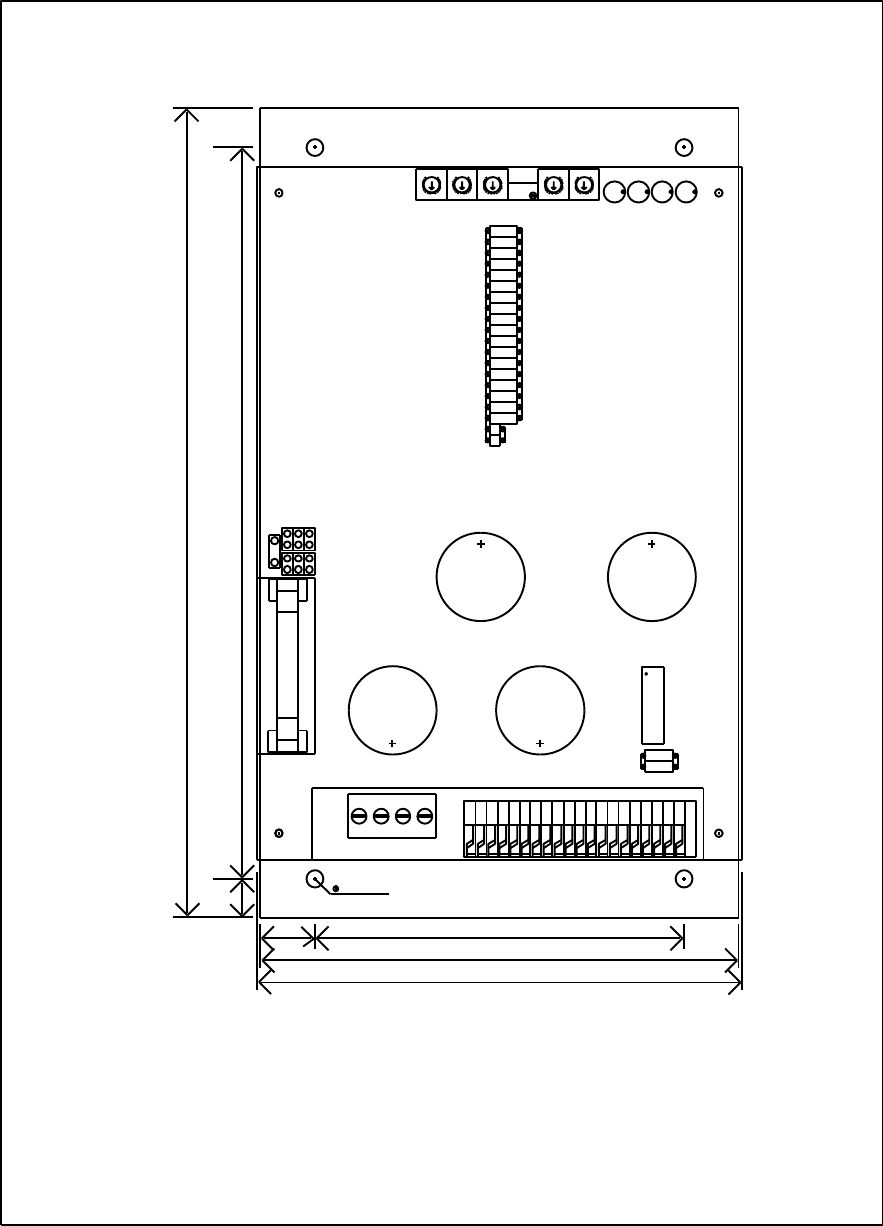
187 169
85
12.5
4.0 x 4
9
110
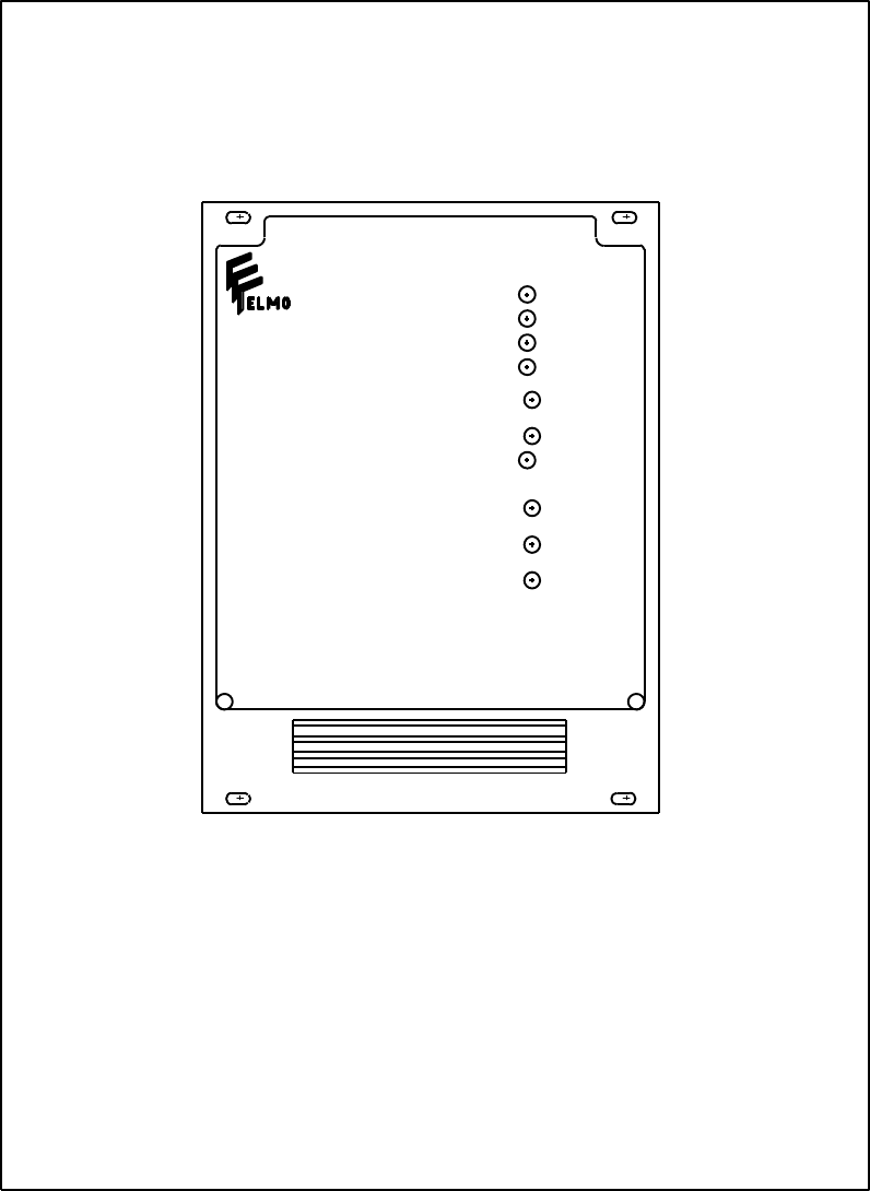
111.76
SP1 - TOP VIEW

51
ISP - Rev 6/95
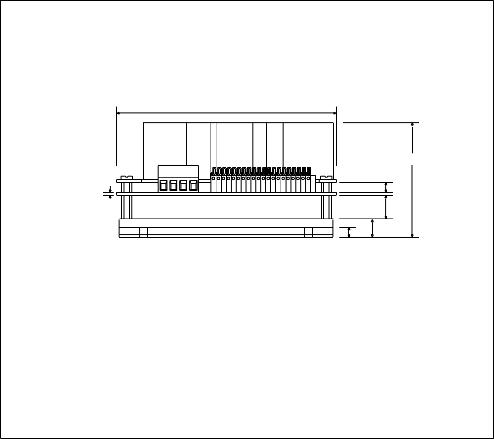
39
22.6 29.4
13.6
4.0
187
SP1 - SIDE VIEW 1
52
ISP - Rev 6/95
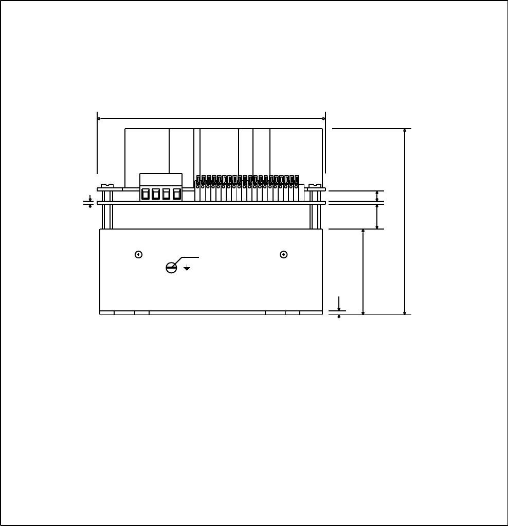
111.76
12
39
5.2
1.6
59
SP1 - SIDE VIEW 2
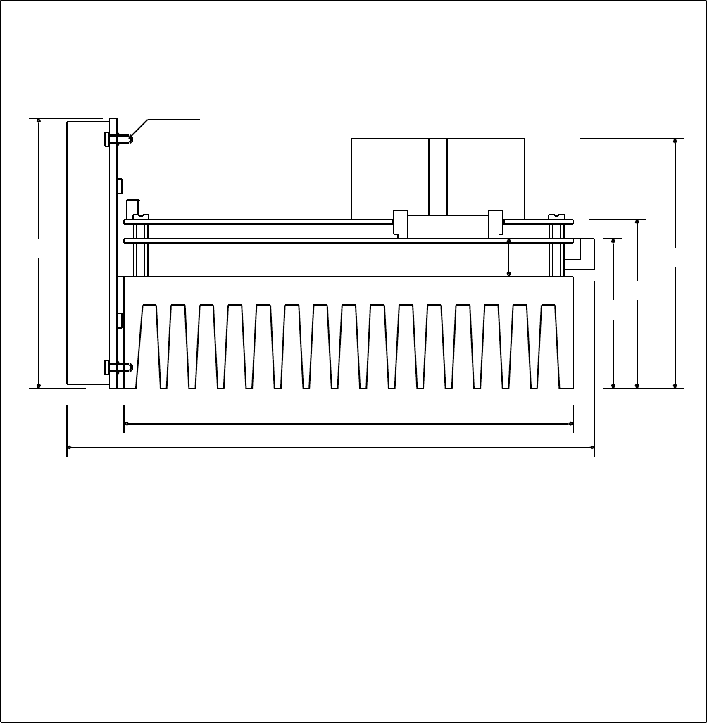
53
ISP - Rev 6/95
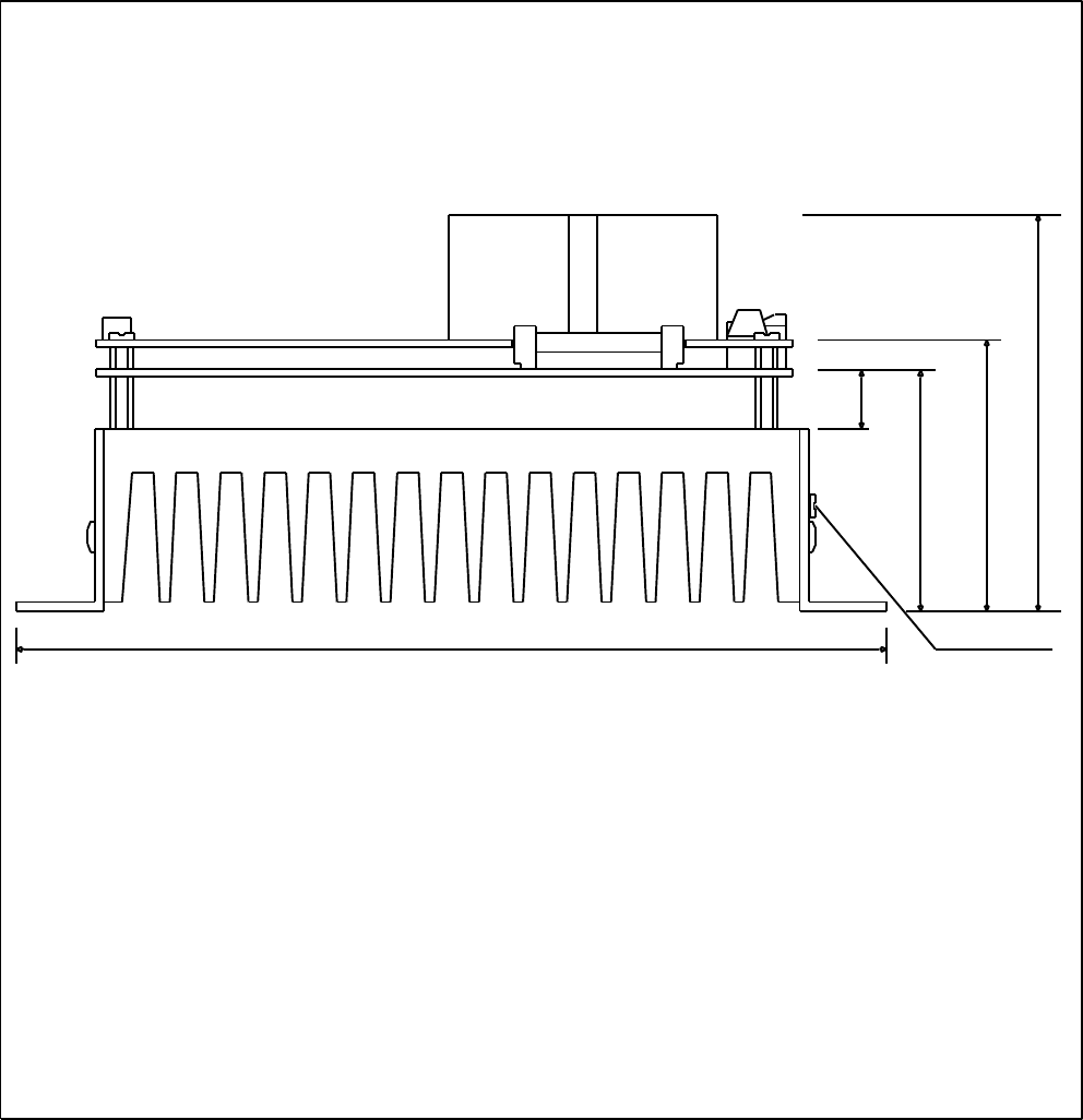
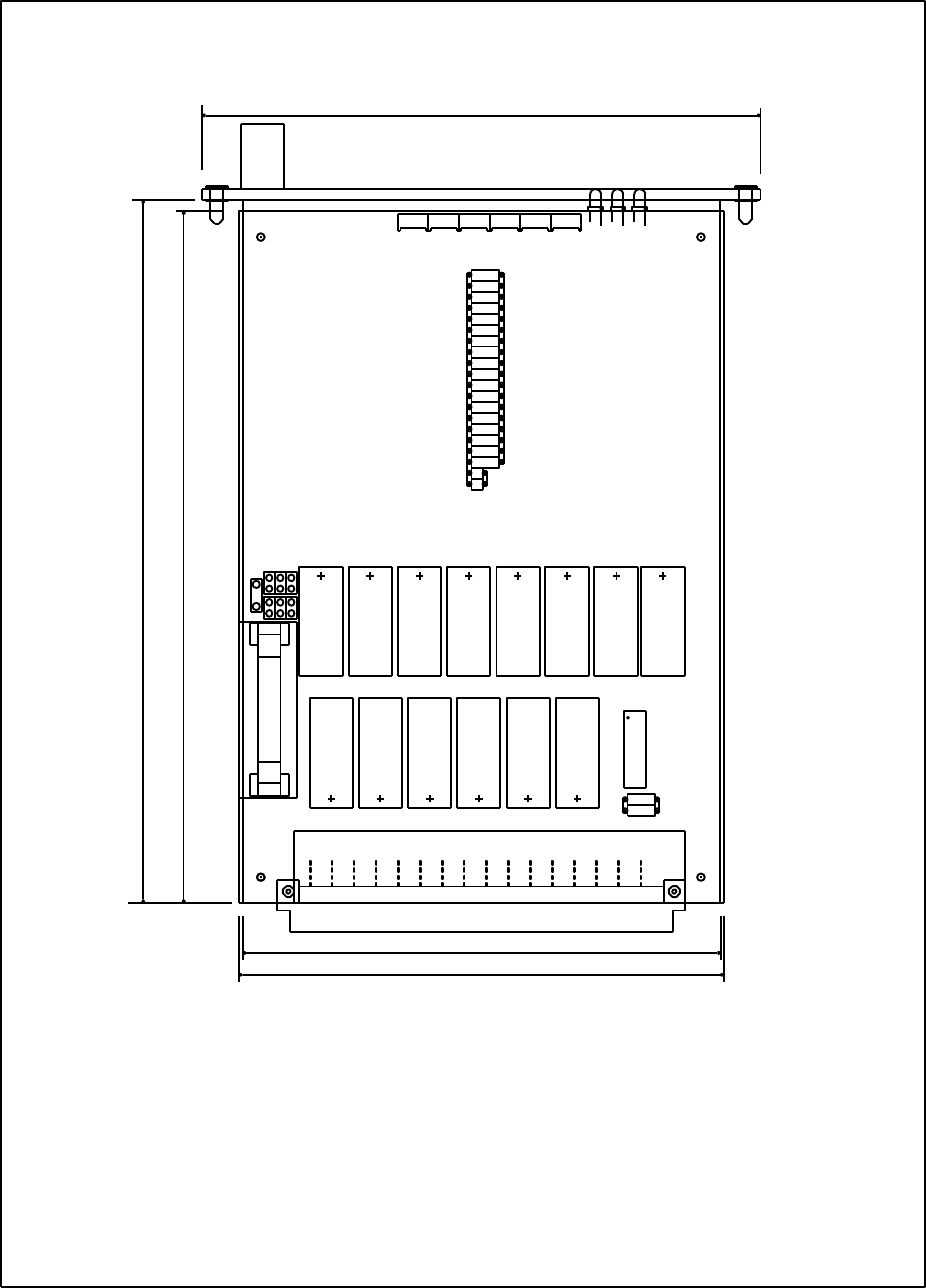
200 182
SEE DETAIL A
9.5
9
10
9.5
DETAIL A
5
25.5 109
70
111.76
SP2 - TOP VIEW
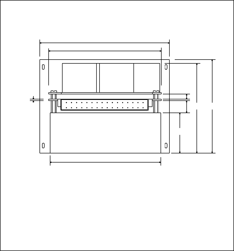
54
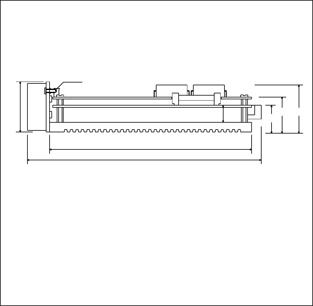
ISP - Rev 6/95
55.6 62.4
13.6
GROUNDING
SCREW M4
200
SP2 - SIDE VIEW 1
74
55
ISP - Rev 6/95
111.76
5.2
12
1.6
M4
42
72
2
SP2 - SIDE VIEW 2
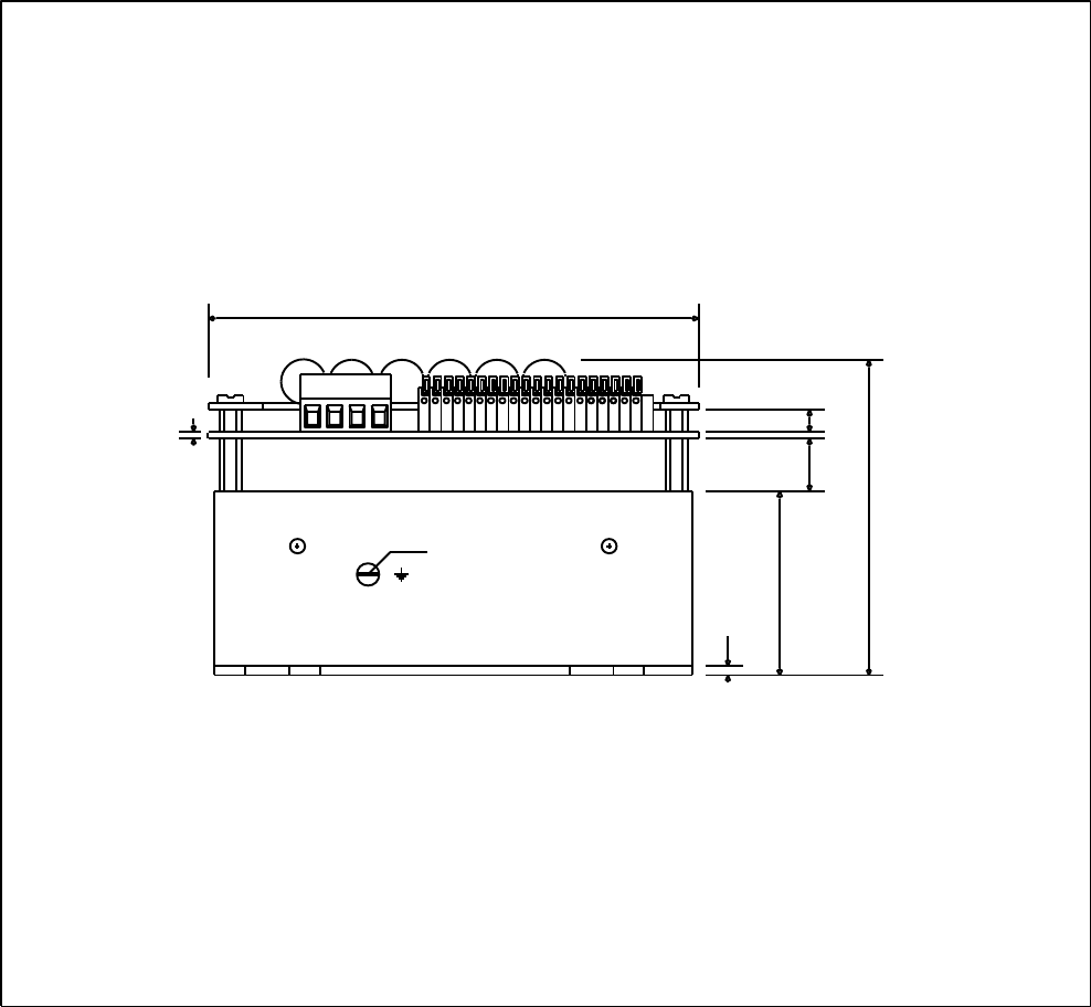
56
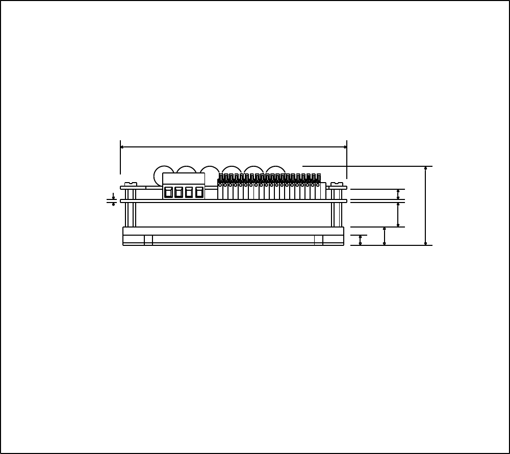
ISP - Rev 6/95
187 169
85
12.5
4.0 x 4
9
110
111.76
SP3 - TOP VIEW

57
ISP - Rev 6/95
39
22.6 29.4
13.6
4.0
187
SP3 - SIDE VIEW 1
58
58
ISP - Rev 6/95
59
SP3 - SIDE VIEW 2
111.76
5.2
12
1.6
58

59
ISP - Rev 6/95
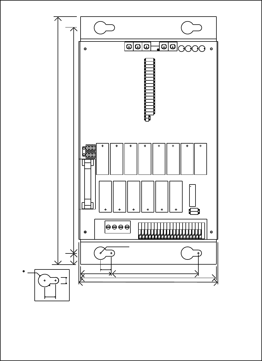
200 182
70
SEE DETAIL A
9.5
25.5
9
10
9.5
DETAIL A
5
109
111.76
SP4 - TOP VIEW
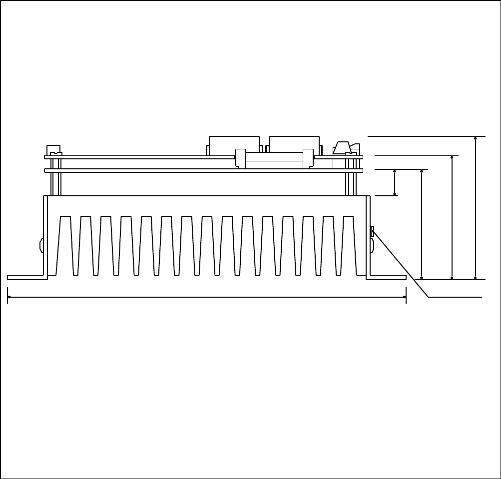
60
ISP - Rev 6/95
91
55.6 62.4
13.6
GROUNDING
SCREW M4
200
SP4 - SIDE VIEW 1
61
ISP - Rev 6/95
111.76
5.2
12
1.6
M4
42
91
2
SP4 - SIDE VIEW 2
62
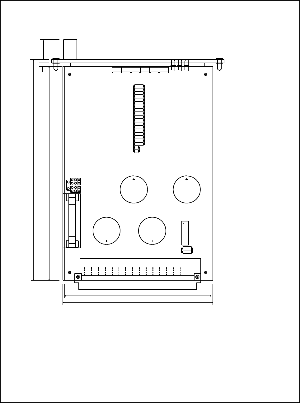
ISP - Rev 6/95
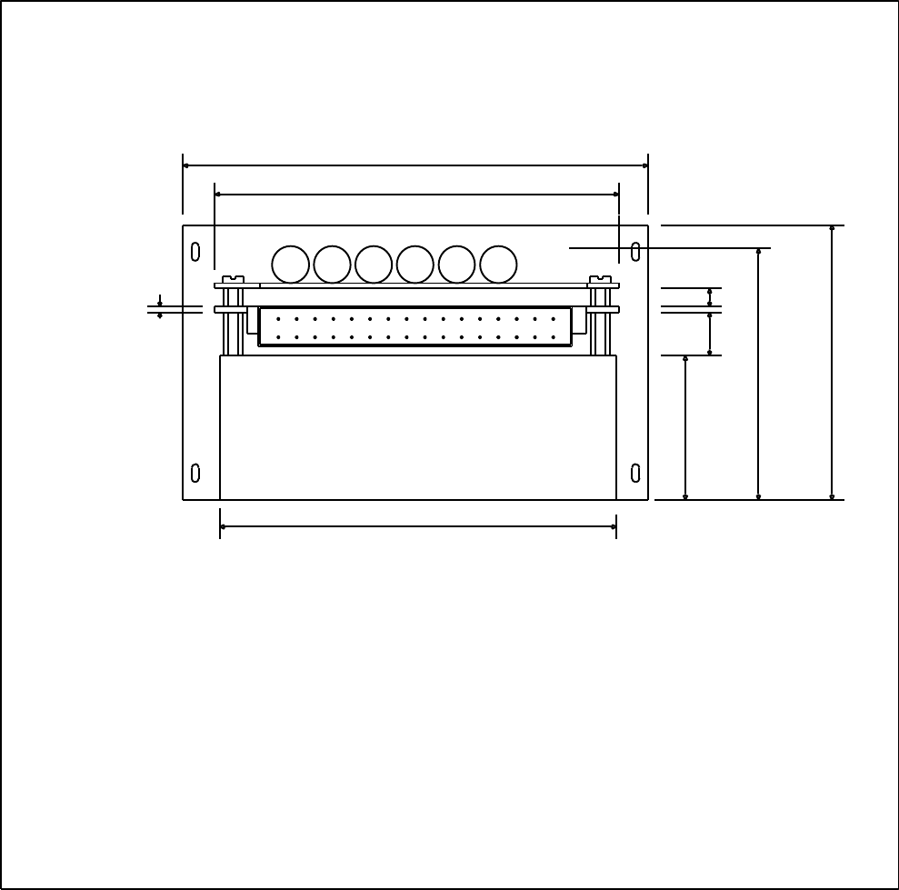
128.7
ISP RACK MOUNTING (8T and 15T) - TOP VIEW
160162.54
110
J1
111.76
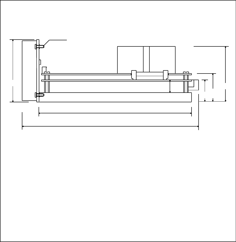
63
ISP - Rev 6/95
ISP RACK MOUNTING (3U/8T) - SIDE VIEW 1
2 x M3
40.64
3929.4
22.6
13.6
162.54
188

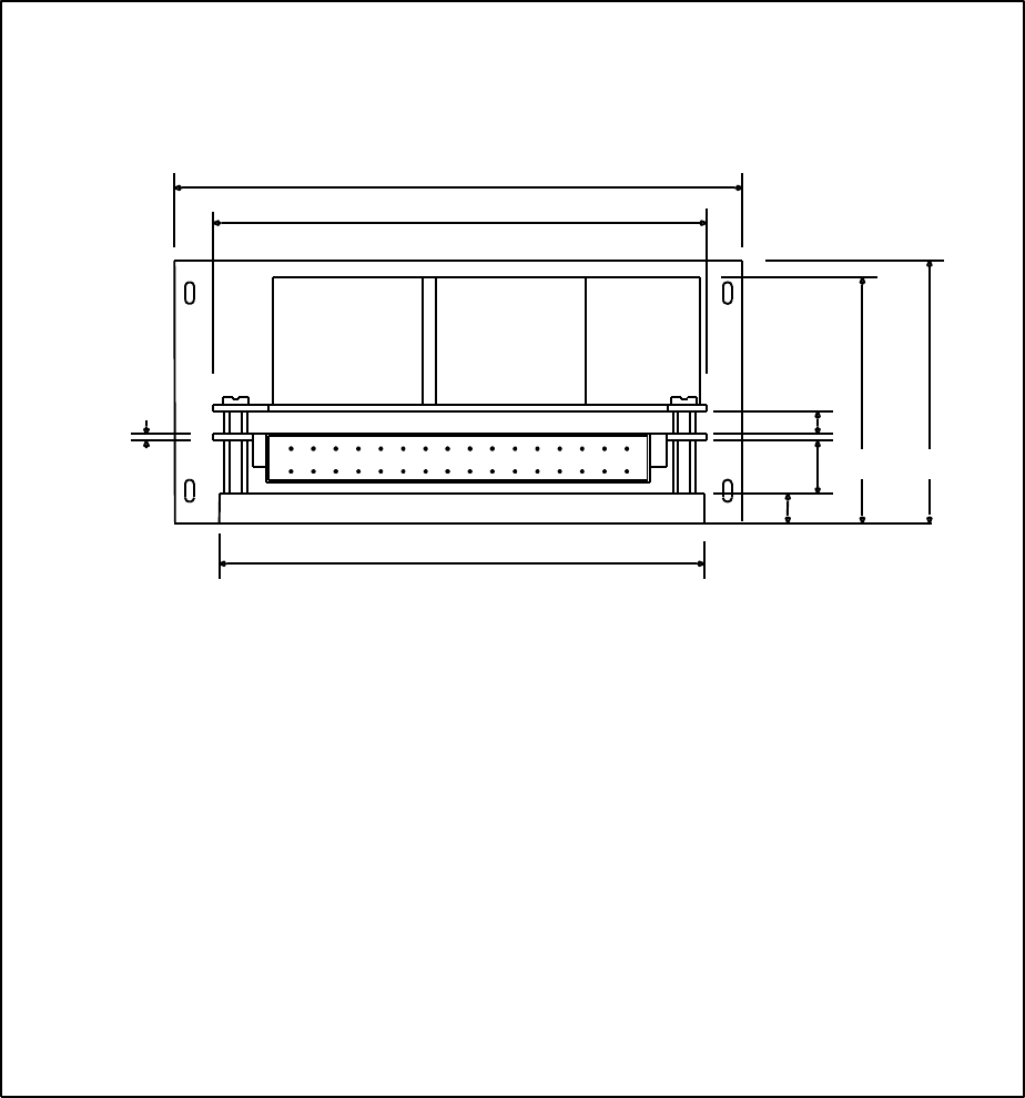
64
ISP - Rev 6/95
ISP RACK MOUNTING (3U/8T) - SIDE VIEW 2
111.76
128.7
1.6
8
5.2
12
38
65
ISP - Rev 6/95
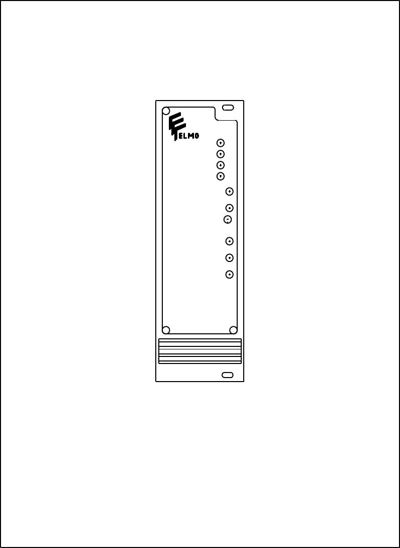
+
SO
IC
IN
VS
COMP.
GN1
GN2
BAL.
IP
IC
+
FRONT PANEL FOR ISP 3U/8T

66
ISP - Rev 6/95
ISP RACK MOUNTING (3U/15T) -SIDE VIEW 1
4 x M3
7060.4
53.6
13.6
76.2
160
188
67
ISP - Rev 6/95
ISP RACK MOUNTING (3U/15T) - SIDE VIEW 2
128.7
111.76
1.6 5.2
12
70 76.2
40
109
68
ISP - Rev 6/95
FRONT PANEL FOR ISP 3U/15T
+
SO
IC
IN
GN1
GN2
BAL.
VS
IP
IC
COMP.
69
ISP - Rev 6/95
ISP RACK MOUNTING (3U/12T and 3U/19T) - TOP VIEW
2.5
15
160165
J1
109
111.76
70
ISP - Rev 6/95
4 x M3
ISP RACK MOUNTING (3U/12T) -SIDE VIEW 1
60.96
28.4
59
21.6
13.6
162.45
188
71
ISP - Rev 6/95
ISP RACK MOUNTING ( 3U/12T) - SIDE VIEW 2
128.7
111.76
12 59 60.96
5.2
1.6
8
109
72
ISP - Rev 6/95
FRONT PANEL FOR ISP 3U/12T
SO
IC
IN
VS
GN1
GN2
BAL.
COMP.
IP
IC
73
ISP - Rev 6/95
4 x M3
ISP RACK MOUNTING (3U/19T) -SIDE VIEW 1
96.52
60.4
89
53.6
13.6
160
188
74
ISP - Rev 6/95
ISP RACK MOUNTING ( 3U/19T) - SIDE VIEW 2
128.7
111.76
12 89 96.52
5.2
1.6
40
109
75
ISP - Rev 6/95
FRONT PANEL FOR ISP 3U/19T
SO
IC
IN
VS
GN1
GN2
BAL.
COMP.
IP
IC
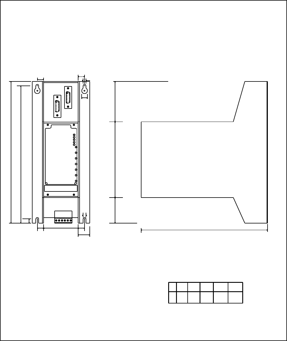
76
ISP - Rev 6/95
SIDE VIEW
FRONT VIEW
ENCLOSURE MECHANICAL OUTLINE
11
11
10
5
74.2
132.5
240
251.7
222
45.0
20
5
11
11 X
POWER
7.5
NOTE:
ALL DIMENSIONS ARE IN mm.
X102.7
12T 20T16T
62.0 82.3
24T 36T
123.0 184.0
Standard Sizes
For non-standard sizes:
X = 5.08 x n + 1mm

77
ISP - Rev 6/95
List of ELMO Service Centers
ISRAEL
Elmo Motion Control LTD
34 Segula ST.
Petah-Tikva 49103
Tel: (03)934-5059
Fax: (03)934-5126
EUROPE
Elmo Motion Control
7 Stanserstrasse
CH-6362 Stansstad
Switzerland
Tel: (041)610775
Fax: (041)610778
U.S.A
Elmo Motion Control INC.
1200 Woodruff Road,
Suite C-22,
Greenville, SC 29607-5731
Tel: (803) 288-9316
Fax: (803) 288-9318
