Elpas Solutions 3-62817 Access control system for two doors controlling User Manual
Elpas Solutions Ltd. Access control system for two doors controlling Users Manual
Users Manual
VisAccess AXS-100, AXS-100XT
Indoor Two-Door Proximity Access Control System
1. INTRODUCTION
The AXS-100/AXS-100XT is an electronic access control system
for controlling two doors.. Eight controllers can be networked
together to control a total of 16 doors. The controller relay
activates a lock or an electromagnetic strike (EMS), when a valid
proximity key card or tag is presented to the reader. For detailed
system description, refer to the AXS-100/AXS-100XT user’s
guide.
The use of a proximity (non-contact) key makes the installation of
the AXS-100/AXS-100XT system an attractive possibility in harsh
environments and in places with poor lighting conditions.
The proximity keys are totally sealed and wear resistant. The lock
reads the key ID, whenever the key is held close to the reader.
Installation Guide
2. SPECIFICATIONS
AXS-100, AXS-100XT CONROLLER
Power Input: 14 - 16.5 VAC, 50VA
Max Current Consumption: 2.5A
Memory Capacity: 5,000 access card codes
Event Log: 1000 records per controller
Time Schedules: 64 separate schedules. Each key may be
assigned to 2 schedules.
Dry Contact Relay: Max 1A continuous
Doors Per Controller: Up to 2
Readers Per Controller: Up to 2 external + 1 internal (for programming)
Controllers Per Network: 8
Inputs (x 2 doors): Request-to-exit, door position, 2 programmable inputs
Outputs: 2 lock relays, NO/NC dry contact, 30VDC 2A max
1 auxiliary relay, NO/NC dry contact, 30V DC 2A max
Output power for 2 locks: 10.3 - 12VDC, 400mA max
2 readers output: 70 mA max
Anti Passback (APB) Modes:
1. Local to each controller
2. Network APB
Indicators (LEDs): 5 (see figure 5)
Operating Temperatures: 0°C to 50°C (32°F to 122°F)
Dimensions (LxWxD): 315x262x74mm (12-3/8x10-5/16x10-15/16 in)
Weight: AXS-100: 3.8 kg (8.4 lb)
AXS-100XT: 3 kg (6.6 lb)
Color: White
Operation is subject to the following two conditions: (1) This
device may not cause harmful interference, and (2) this device must
accept any interference received, including interference that may
cause undesired operation.
READERS
Operating Temperatures: -20°C to 50°C (-4°F to 122°F)
Color: Dark brown
Minimum distance between readers: 60 cm (2 ft)
RDR-4 PROXIMITY READER
Weight: 121.5 g (4.3 oz)
Indicators: Tricolor LED (Green, Red, Amber)
Cable (to AXS-100/AXS-100XT control unit) maximum length:
22 AWG up to 60 m (200 ft)
18 AWG up to 100 m (320 ft)
Dimensions (LxWxD): 116 x 70 x 16.8 mm (4-1/2 x 2-3/4 x 5/8 in)
RDK-4 PROXIMITY READER WITH KEYPAD (optional, not evaluated by UL)
Weight: 170 g (6 oz)
Power input: 12-16V DC from the AXS-100 / AXS-100XT
Buttons: 12 (numeric keypad)
Dimensions (LxWxD): 122x82x31mm (4-13/16 x 3-1/2 x 1-1/4 in)
CARDS (*)
CRD-1SL ISO STANDARD SLOTTED AND NUMBERED
PROXIMITY CARD
Card ID: One of a trillion different combinations
Dimensions (LxWxD): 85x54x1mm (3 5/16 x 2 1/8 x 1/32 in)
Weight: 2.5 g (0.1 oz)
Color: White
CRD-25SL: Package of twenty-five CRD-1SL slotted proximity
cards with print
CRD-25: Package of twenty-five CRD-1 non-slotted proximity cards
(optional).
CRD-25S: Slotted proximity card
TAGS (*)
TAG-1: One proximity tag
* Both cards and tags contain 40-bit code and using
Manchester encoding
.
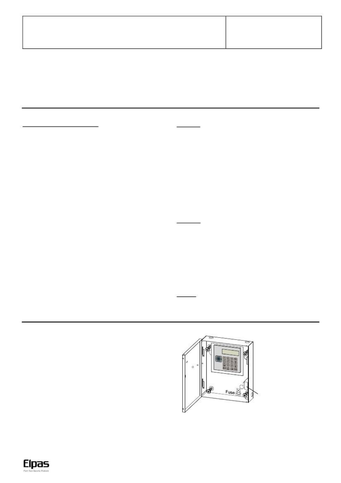
3. MOUNTING
3.1 Metal Box Mounting
The system must be installed indoors, within the protected
premise, in accordance with the National Electrical Code
(NFPA70) and the local authorities having jurisdiction.
For AXS-100XT use only the supplied plug-in transformer:
PRI 120V/60Hz @ 0.59A, SEC 16.5VAC / 50VA
BE116250CAA0040, Basler Electric, Class 2 NOT WET,
Do not connect (the transformer) to a power receptacle that is
controlled by a switch.
Use the box as a template
to mark on the mounting
surface, drill 4 holes on the
mounting surface and
fasten the box to the
mounting surface by using
4 screws.
Transformer (AXS-100 only).
In AXS-100XT there is no
transformer.
Figure 1 - Mounting
www.elpas.com
Page 1 of 5
DE6280_V12_09/13
VisAccess AXS-100, AXS-100XT– Installation Guide
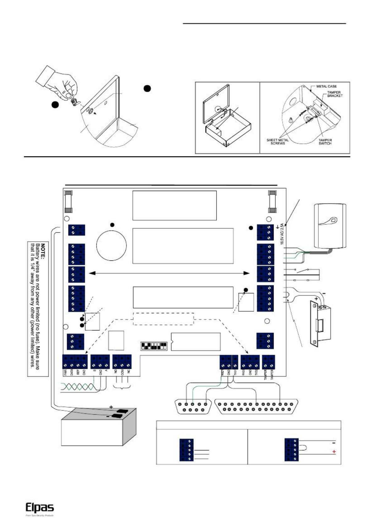
3.2 Metal Box Door Lock Assembly
The door lock assembly of the system metal box is presented in
figure 2 (the lock and the brass nut are supplied in the system
accessories box).
3.3 Backup Battery Installation (Optional)
Locate the optional backup battery (12V, 7.0Ah, Lead-acid
battery) in the lower left side of the system enclosure (see fig. 3).
3.4 Tamper Switch Installation & Wiring
It is necessary to protect the controller against tampering. A UL
Listed Tamper switch must be installed (see fig. 4) and wired to
AUXIN1 and COM of lock #3 of each controller.
2
1
Align lock with the pre-
pu n c h e d h o le a n d
insert it into the hole.
Place the brass nut on the
lock, tighten by hand and
finally tighten with
spanner (7/8”). Verify that
you can lock the door (key
rotation of 90 degrees).
Metal box
Metal box door
Backup
battery
(optional)
Figure 2 - Metal Cabinet Door Lock Assembly
Fig. 3 - Backup Battery Fig. 4 - Tamper Switch Installation
4. WIRING
AXS-100, AXS-100XT Wiring Diagram
F
2
Battery fuse 3.15A
LD3 (green LED)
ext. batt. charged
Replace fuses (x2) with UL
Listed fuses.
WARNING: To reduce risk of
fire, replace only with the same
type and rate of fuse.
NOTE:
Replace battery with PANASONIC.
Type: CR2032, 3V “COIN” battery.
Use of another battery may present
a risk of fire or explosion.
AC fuse 3.15A
LD2 (red LED)
Power ON
F
3
Plug-in transformer for AXS-100XT
only: PEI 120V/60Hz @ 0.59A,
S E C . 1 6 . 5 V A C / 5 0 VA .
B E 11 62 50 CA A 00 40 , B as l er
Electric. Class 2 NOT WET,
UL Listed 49HO.
Prox. Reader
BAT-
BAT+
READER 1
PWR
GND
TX
RX
RTE
GND
DPOS
RELAY 1
GND
PWR
NO
COM
NC
AC
AC
READER 2
PWR
GND
TX
RX
RTE
GND
DPOS
battery
-
+
holder
See user manuals for safety instructions.
Red
Black
Green
White
Symmetrical connectors
Door 1Door 2
LD4 (red LED) alarm
relay activated
LD5 (green
LED) output
relay activated
RTE input
RELAY 2
GND
PWR
NO
COM
NC
D.POS input
NOTE:
All power outputs are power limited
except from the battery outputs.
Note:
Optional for future use
DIP Switches
LD1 (green LED)
output relay
activated
DOOR 2
IN1
GND
IN2
DOOR 1
IN1
GND
IN2
EPROM
Wire Jumper
(remove for dry contact)
Twisted pair to A,B
of other AXS-100
Common gnd to
other AXS-100
must be connected!
Alarm relay
to Siren or
Bell
DB-9F
To computer
COM1 or COM2
1 2
6
3
7
4
8
5.
9
13 12 11 10
9
8
7
6
5
4
3
DB-25M
To serial printer
2
1
25 24 23 22 21 20 19 18 17 16 15 14
NOTE:
For battery
replacement
see
installation
instructions.
12V, 7.0Ah
Lead-acid battery
(optional)
Lock connection configurations
Dry contact connectionInternal 12V power supply
GND
PWR
N.O.
COM
N.C.
Normally open (EMS)
Common
Normally closed (maglock)
GND
PWR
N.O.
COM
N.C.
Figure 5 - Wiring
www.elpas.com
Page 2 of 5
DE6280_V12_09/13
VisAccess AXS-100, AXS-100XT – Installation Guide
Each two-door controller connects to two proximity readers and two
electric locks. It can also be connected to two inputs per door:
Request-to-Exit (RTE) button or PIR near the door in the
secure area will allow a person to open the door from within for
leaving.
Door Position micro switch installed between the door and door
frame will provide the controller with door status indications.
12VDC
Normally Open
NC
COM
NO
PWR
GND
----- Power
----- Power+Power+
Jumper
12VDC
Normally Closed
NC
COM
NO
PWR
GND
----- Power
Jumper
----- Power+
Non-12VDC or
high current
devices - Dry
contact N.O.
NC
COM
NO
PWR
GND
------
------
Non-12VDC or
high current
devices - Dry
contact N.C.
NC
COM
NO
PWR
GND
------
------
A. Proximity Readers
Each reader is connected to the controller via a 4-wire cable. The
standard cable is color coded as follows:
REDPower +
BLACK Power –
GREEN TX
WHITE RX
Use an extension cable with the same colors to avoid connection
errors.
Note: Do not install the RDR-4 on a metal surface or a metal
door frame, since this decreases the read range significantly. If
you have to install the reader on a metal surface, use a spacer
so that the reader will be at least 1 cm (3/8 in.) away from the
metal. You may use RDR-BACK which is an optionally
available spacer made specifically for this purpose
Note: When installing more than one RDR-4, the distance
between them should be at least 60 cm (2 ft.), to ensure proper
operation.
The lock sections include also 12V power connectors. These
connectors provide power to the lock with a current limit of 400mA
for each lock. The controller supplies power from a backup battery if
available when the AC power is down. Electromagnetic locks which
constantly draw a large current, should use the dry contact ONLY
without connecting the internal power supply. The same holds true
for any other device, which does NOT operate at 12VDC.
If you notice problems with a controller operating an EMS that
uses an internal power supply, connect the diode supplied
between + and – of the EMS output (see Panel Wiring Diagram).
D. Controller Network
Up to eight system controllers can be connected together in a
network. The controller provides two 3-connector blocks for daisy
chaining controllers in a bus configuration.
The controllers’ addresses need not be in the physical order
of connection.
Connect system units with a single twisted pair cable.
Connect terminal A to A and B to B, GND to GND, this way up to
eight controllers.
B. Inputs
Both inputs (RTE and Door Position) can be connected to either
normally open or normally closed switches. The default is a
normally open RTE and normally closed Door Position (when
door is shut).
F. Power Connection
Connect the AC power cable to the power connector on the top
right side of the board.
G. Backup Battery Connection
Connect backup battery to black and red wires on the left side.
C. Locks
The system can operate both electromagnetic strikes - EMS
(normally open) and electromagnetic locks - EML (normally
closed). Each connector block has a COMMON as well as N.O.
and N.C. connectors.
If the controller is configured for one door, connect it to the
EMS/EML, at the left side of the controller.
All types of connections are detailed in the next drawing.
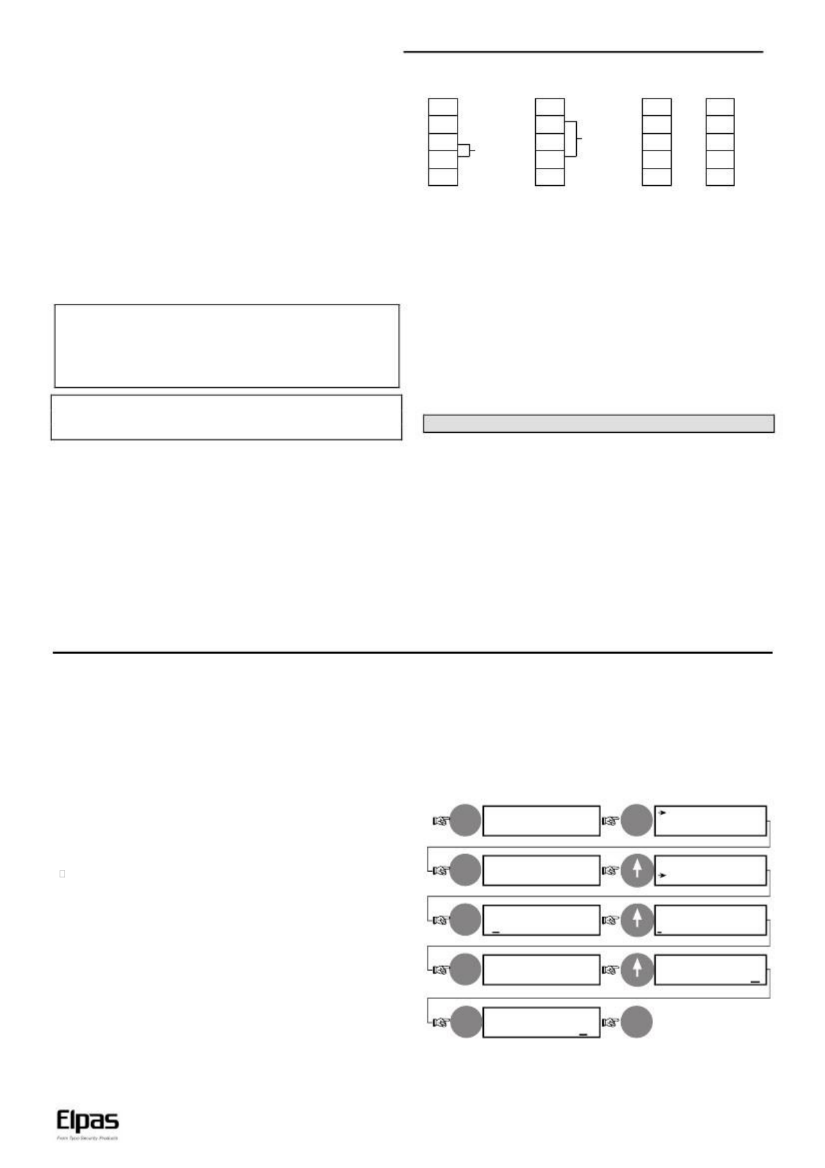
5. SPECIAL INSTALLER FUNCTIONS
The AXS-100 / AXS-100XT system has a few special functions,
which should not be accessible to the regular user. These
functions allow the installer to initialize the system to a known
state before starting to set up user data. The functions are:
Reset passwords
Clear key database
Load setup defaults
Setting address & operation mode
The controller will prompt you with a “Y/N”. Press “1”
followed by another Enter to confirm.
The keys database will be erased. The operation will be
logged and printed as “DB ERASED”.
5.3 Setup Defaults
To return the system to its default setup, perform the actions that
are shown in figure 6 (text in rectangles represents displayed text).
Enter
5.1 Reset Passwords
If password #1 is not known, it is impossible to change some
system parameters. The following steps reset the passwords:
When the idle screen is displayed, repeatedly press the arrow up
( ) key until a long beep is heard. As a result, Password #1 has
been reset to “2975”. Password #2 is cleared.
ENTER PASSWORD
XXXX
DATE TYPE
Enter
SETUP
EDIT KEYS
EDIT REGISTER
LOCAL SETUP
SETUP FLAGS 1
------78
LOAD SETUP
DEFAULTS (Y/N)N
Enter DATE/TIME
5.2 Clear Keys Database
It is recommended to clear the key database before starting to
program user keys for the first time.
This operation should be performed from controller #1.
Follow these steps to clear the keys database:
Enter
APB RESET HOUR
99:00
PC PASSWORD
Enter 65535
(16 times)
Enter password #1 and log in into the system.
In EDIT KEYS menu select DELETE KEY screen.
Enter 9999 as the key number and press Enter.
1
LOAD SETUP
DEFAULTS (Y/N)Y
Enter (long beep is heard
to indicate success)
Figure 6 - Returning to Setup Defaults
www.elpas.com
Page 3 of 5
DE6280_V12_09/13
VisAccess AXS-100, AXS-100XT– Installation Guide
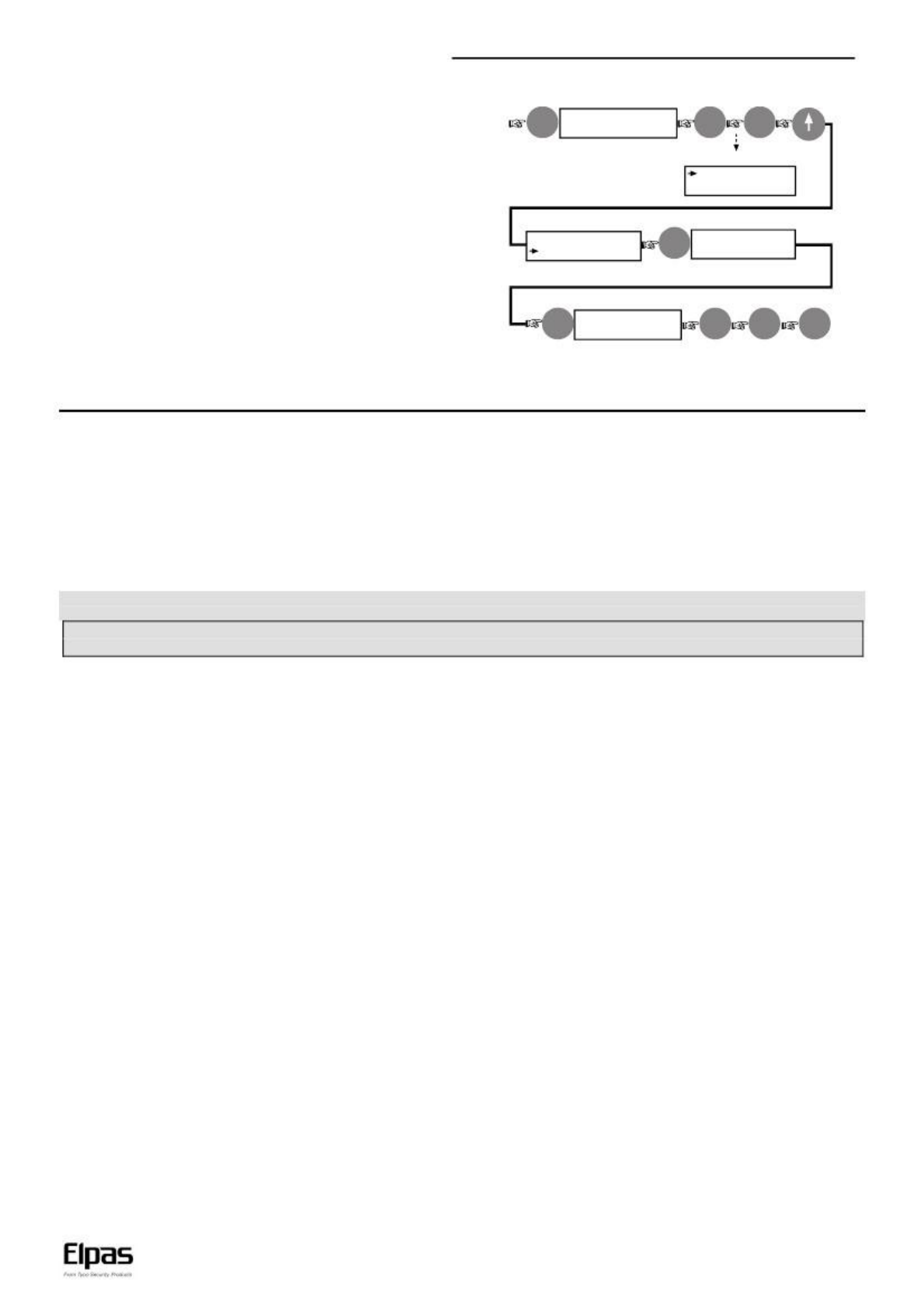
5.4 Setting Address & Operation Mode
Setting the controller address and operation mode, in AXS-100 /
AXS-100XT version 2.06 and above, is performed by using the
controller keypad (not by using DIP switches) - see figure 7.
Enter
ENTER PASSWORD
XXXX
Enter
Enter
The display will be:
SETUP
EDIT KEYS
Enter controller No. (e.g. 1)
EDIT REGISTERS
LOCAL SETUP
Enter
4 times
CONTROLLER
1
Select operation mode (e.g. 7)
Enter
MODE
7
Note: Mode list is attached
to the AXS-100 door.
Enter
Esc
Esc
Figure 7 - Controller Address and Operation Mode Setting
6. MAINTENANCE
6.1 Replacement Parts List
1. Lithium battery 3V, cat. No. 0-9913-0.
2. CRD-1, cat. No. 0-9923-2, or 0-9923-8.
3. Proximity reader RDR-4, cat. No. 3-6304-0
6.3 Lithium Battery Handling/Disposal
Caution: Battery may explode if mistreated, do not recharge,
disassemble or dispose in fire.
Replace battery with PANASONIC Coin battery type CR2032, 3V
only. Use of another battery may present a risk of fire or explosion.
Dispose any used Lithium battery only in an approved disposal
container.
6.2 Periodic Check
Once a month, the system must be checked by presenting a
tag/card to the reader and verifying that the proper door is opened.
This device complies with the essential requirements and provisions of Directive 1999/5/EC of the European Parliament and of the Council of 9
March 1999 on radio and telecommunications terminal equipment.
WARNING! Changes or modifications to this unit not expressly approved by the party responsible for compliance could void the user's
authority to operate the equipment.
7. REGULATORY
7.1 EU Declaration of Conformity
This equipment is in compliance with the essential requirements
and other relevant provisions of Directive 1999/5/EC.
However, there is no guarantee that interference will not occur in
a particular installation. If this equipment does cause harmful
interference to radio or television reception, which can be
determined by turning the equipment off and on, the user is
encouraged to try to correct the interference by one or more of
the following measures:
• Reorient or relocate the receiving antenna.
• Increase the separation between the equipment and receiver.
• Connect the equipment into an outlet on a circuit different from
that to which the receiver is connected.
• Consult the dealer or an experienced radio/TV technician for
help.
Changes or modifications to this equipment not expressly
approved by the party responsible for compliance (Elpas
Solutions Ltd.) could void the user’s authority to operate the
equipment.
7.2 Compliance FCC Compliance
These devices (FCC #:04X3-62817) complies with FCC Rules
Part 15.
Operation is subject to the following two conditions:
(1) This device may not cause harmful interference, and
(2) This device must accept any interference received, or that
may cause undesired operation.
Note: This equipment has been tested and found to comply with
the limits for a Class B digital device, pursuant to part 15 of the
FCC Rules. These limits are designed to provide reasonable
protection against harmful interface in a residential installation.
This equipment generates; uses and can radiate radio frequency
energy and, if not installed and used in accordance with the
instructions, may cause harmful interference to radio
communications
7.3 Company Contact
Elpas, Inc.
Westford, Massachusetts (USA) -Tel: 1-800-223-0020
www.elpas.com
Page 4 of 5
DE6280_V12_09/13

VisAccess AXS-100, AXS-100XT– Installation Guide
8. PRODUCT WARRANTY
Elpas Solutions Ltd. (Elpas or the Company), and its affiliates,
warrants its products (hereinafter referred to as "the Product”) to
be free of defects in materials and workmanship under normal
operating conditions and use for a period of one year from the
date of shipment by Elpas. The Company’s obligations shall be
limited within the warranty period, at its option, to repair or to
replace the defective Product or any defective component or part
thereof. To exercise this warranty, the product must be returned
to the manufacturer freight prepaid and insured.
This warranty does not apply to repairs or replacement caused by
improper installation, Product misuse, failure to follow installation
or operating instructions, alteration, abuse, accident, tampering,
repair by anyone other than Elpas, external causes, and failure to
perform required preventive maintenance. This warranty also
does not apply to any products, accessories, or attachments used
in conjunction with the Product, including batteries, which shall be
covered solely by their own warranties, if any. Elpas shall not be
liable for any damage or loss whatsoever, whether directly,
indirectly, incidentally, consequentially or otherwise, resulting
from a malfunction of the Product due to products, accessories,
or attachments of others, including batteries, used in conjunction
with the Product.
Elpas MAKES NO EXPRESS WARRANTIES EXCEPT THOSE
STATED IN THIS STATEMENT. ELPAS DISCLAIMS ALL
OTHER WARRANTIES, EXPRESS OR IMPLIED, INCLUDING
WITHOUTLIMITATIONIMPLIEDWARRANTIESOF
MERCHANTABILITY AND FITNESS FOR A PARTICULAR
PURPOSE.ELPAS’SSOLERESPONSIBILITYFOR
WARRANTY CLAIMS IS LIMITED TO REPAIR OR TO
REPLACE AS SET FORTH IN THIS STATEMENT.
Elpas shall have no liability for any death, personal injury,
property damage, or other loss whether direct, indirect, incidental,
consequential, or otherwise, based on a claim that the Product
failed to function. However, if Elpas is held liable, whether directly
or indirectly, for any loss or damage arising under this limited
warranty or otherwise, regardless of cause or origin, the
company's maximum liability shall be limited to the purchase
price of the Product, which shall be fixed as liquidated damages
and not as a penalty, and shall be the complete and exclusive
liability of Elpas.
Elpas shall not, under any circumstances whatsoever, be liable
for any inaccuracy, error of judgment, default, or negligence of
Elpas, its employees, officers, agents, or any other party, or of
the purchaser or user, arising from any assistance or
communication of any kind regarding the configuration, design,
installation, or creation of security system involving the Product,
that being the responsibility of the purchaser or user.
If Elpas is unable to make such repair or replacement, the
company’s entire liability shall be limited to the cost of a
reasonable substitute product. Elpas shall not be responsible for
any dismantling, installation, reinstallation, purchasing, shipping,
insurance, or any similar charges Elpas shall have no liability for
any damages, including without limitation, any direct, indirect,
incidental, special, or consequential damages, expenses, costs,
profits, lost savings or earnings, or other damages arising out of
the use of the Product or the removal, installation, reinstallation,
repair or replacement of the Product or any related events. In the
event that there is any liability against Elpas, such liability shall be
limited to the purchase price of the Product which amount shall
be fixed as liquidated damages.
The purchaser and user understand that this Product may be
compromised or circumvented by intentional acts; that the
Product will not in all cases prevent death, personal injury,
property damage, or other loss resulting from burglary, robbery,
fire or other causes; and that the Product will not in all cases
provide adequate warning or protection. The purchaser and user
also understand that a properly installed and maintained alarm
may reduce the risk of events such as burglary, robbery, and fire
without warning, but it is not insurance or a guarantee that such
events will not occur or that there will be no death, personal
injury, property damage, or other loss as a result of such events.
By purchasing the Product, the purchaser and user shall defend,
indemnify and hold Elpas, its officers, directors, affiliates,
subsidiaries, agents, servants, employees, and authorized
representatives harmless from and against any and all claims,
suits, costs, damages, and judgments incurred, claimed, or
sustained whether for death, personal injury, property damage, or
otherwise, because of or in any way related to the configuration,
design, installation, or creation of a security system involving the
Product, and the use, sale, distribution, and installation of the
Product, including payment of any and all attorney’s fees, costs,
and expenses incurred as a result of any such events.
The purchaser or user should follow the Product installation and
operation instructions and test the Product and the entire system
at least once each week. For various reasons, including but not
limited to changes in environmental conditions, electric,
electronic, or electromagnetic disruptions, and tampering, the
Product may not perform as expected. The purchaser and user
are advised to take all necessary precautions for the protection
and safety of persons and property.
This statement provides certain legal rights. Other rights may
vary
by state or country. Under certain circumstances, some states or
countries may not allow exclusion or limitation of incidental or
consequential damages or implied warranties, so the above
exclusions may not apply under those circumstances and in
those states or countries.
Elpas reserves the right to modify this statement at any time, in
its sole discretion without notice to any purchaser or user.
However, this statement shall not be modified or varied except by
Elpas in writing, and
Elpas does not authorize any single individual to act on its behalf
to modify or vary this statement.
Any questions about this statement should be directed to Elpas.
Page 5 of 5
DE6280_V12_09/13
W.E.E.E. Product Recycling Declaration
For information regarding the recycling of this product you must contact the company from which you orignially purchased it.
If you are discarding this product and not returning it for repair then you must ensure that it is returned as identified by your supplier .
This product is not to be thrown away with everyday waste - Directive 2002/96/EC Waste Electrical and Electronic Equipment.