Elpas Solutions 5-LFB00125 PROXIMITY BUS READER User Manual Proximity BUS Reader Wiring Guide
Elpas Solutions Ltd. PROXIMITY BUS READER Proximity BUS Reader Wiring Guide
User Manual
www.elpas.com
Page 1 of 6
V10/March 2014
Elpas Proximity BUS Reader
P/N: 5-LFA00125
Installation Guide
Introduction
This installation guide provides basic instructions for common Proximity BUS Reader installation scenarios. For UL 294 Compliant Applications
refer to page 4 of this document for a listing of applicable installation considerations.
CAUTION: It is important that you read, understand, and follow the instructions in this document. If you have questions, call your local Elpas
support representative. All reasonable efforts have been made to ensure that the specifications and other information in this guide are accurate
and complete at the time of its publication. Nonetheless, all information contained within this document is subject to change at any time without
prior notice. Any modifications to this equipment without prior written consent of Elpas Solutions Ltd. will void all warranties including the
pertinent regulatory certifications and as such revoke your authority to operate this product. Furthermore unauthorized modifications may also
result in damage to this device and may cause a safety hazard to the users.
Product Description
The Elpas Proximity BUS Reader is a 125KHz, EM4100
compatible; indoor/outdoor surface mounted proximity reader.
The reader features low power consumption, high reliability, and
consistent read ranges (up to 10cm /4 inches), regardless of card
or tag.
Designed for indoor/outdoor environments, the reader’s solid
state electronics is housed in an epoxy potted, (IP-67 rated), of
thermoplastic casing that ensures years of maintenance free
deployments.
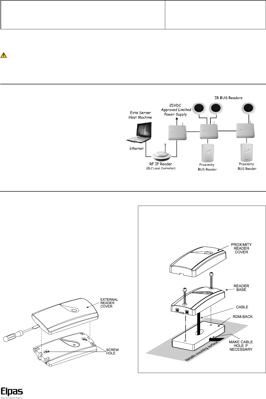
The Proximity BUS Reader contains an onboard I/O that enables
the monitoring of one alarm sensor and control of one digital
open-collector output. The proximity reader also includes a
2m/6.5ft long RS-485 power/data cable for interfacing to a Elpas
BUS Master (a RF IP Reader or an ELC Controller) via a RS-485
Junction Box (P/N:5-JBA00485).
Note: An Elpas RS-485 BUS may contain up to fifteen Elpas BUS devices
(such as RF or IR Readers, Elpas Display Panels, LF Beacons, or other
Proximity BUS Readers) which are wired together using Elpas RS-485
Junction Boxes.
\
LF Proximity BUS Reader - Network Topology
Mounting Considerations
The Proximity BUS Reader should be wall mounted, adjacent to the
opening side of the door (outside of the protected area), at a height
of approximately 1.2m/4ft above the floor
Note: When installing Proximity BUS Readers on adjacent doors,
make certain that the minimum distance between readers is at least
60cm/2.0ft to ensure proper operation.
Mounting Procedure
1. Insert a screwdriver into the recess at the bottom of the case, and
separate the cover from the reader.
2. Place the base on the installation surface, mark two screw holes,
drill the holes, and insert the supplied plastic anchors, if
necessary.
3. Fasten the base to the mounting surface, using the two #6 Tap
screws supplied with the reader.
4. Replace the reader’s cover, ensuring that the cover is aligned with
the reader. This enables the LED to be visible.
Note: Do not install the Proximity BUS Reader directly onto a metal
surface, since can significantly decrease the effective read range of
the device. If you have to mount the reader onto a metal surface,
insert a RDR-BACK (P/N: 3-6317-0) between the device’s reader
base and the metal surface.
Proximity BUS Reader – Installation Guide
www.elpas.com
Page 2 of 6
V10/March 2014
LED Status Indicator
The Proximity BUS Reader contains a tri-colored (Red, Green and
Orange) software configurable LED array that can be used to specify
the status of the device.
Refer to the Eiris Software (V4.7.1 or higher) or the ELC Programmer
Software (V2.1 or higher) Configuration Guides for setup details.
By default, the Red LED is used to indicate the following device
trouble conditions:
o The reader is unregistered (flashes once/sec.)
o The reader has lost RS-485 communication (flashes once/sec.)
RS-485 Interface
The Proximity BUS Reader has one 2m/6.5ft, 6-wire AWG-26
power/data cable with a male RJ-11 connector (6P6C) for connecting
to the RS-485 Junction Box.
I/O Interface
The Proximity BUS Reader also has a 2m/6.5ft, 4-wire AWG-22
cable with ends for connecting two inputs and one digital output.
Color
Conductor Details
Black
Ground
Red
Digital Output
Green
Input 1 (IN1)
White
Input 2 (IN2)
IMPORTANT: BUS Beacons MUST BE powered-down while wiring the unit’s
I/Os and when connecting to the RS-485 BUS. This will prevent accidental
shorts/spikes to cause damage to the devices.
General Purpose Inputs
The Proximity BUS Reader has two general purpose analog
(N.O.) dry contact inputs for monitoring alert sensors or emergency
call buttons designated IN1 and IN2.
EOL supervision may be added to either of these inputs to detect:
Open, Close, Line Cut and Line Short conditions using an End-of-
Line Terminator (P/N: 5-IOX00001).
Note: Elpas End-of-Line Terminators have not been evaluated for use in UL Applications.
Recommended Cable: 22 AWG, unshielded/twisted pair.
Digital Output
The Proximity BUS Reader has one dry contact open-collector
digital output (up to 100mA, 28VDC) for actuating an alert
response device.
Note: The output is resistive loading only, there is no power factor.
Recommended Cable: 22 AWG, unshielded/twisted pair.
Proximity BUS Reader – Installation Guide
www.elpas.com
Page 3 of 6
V10/March 2014
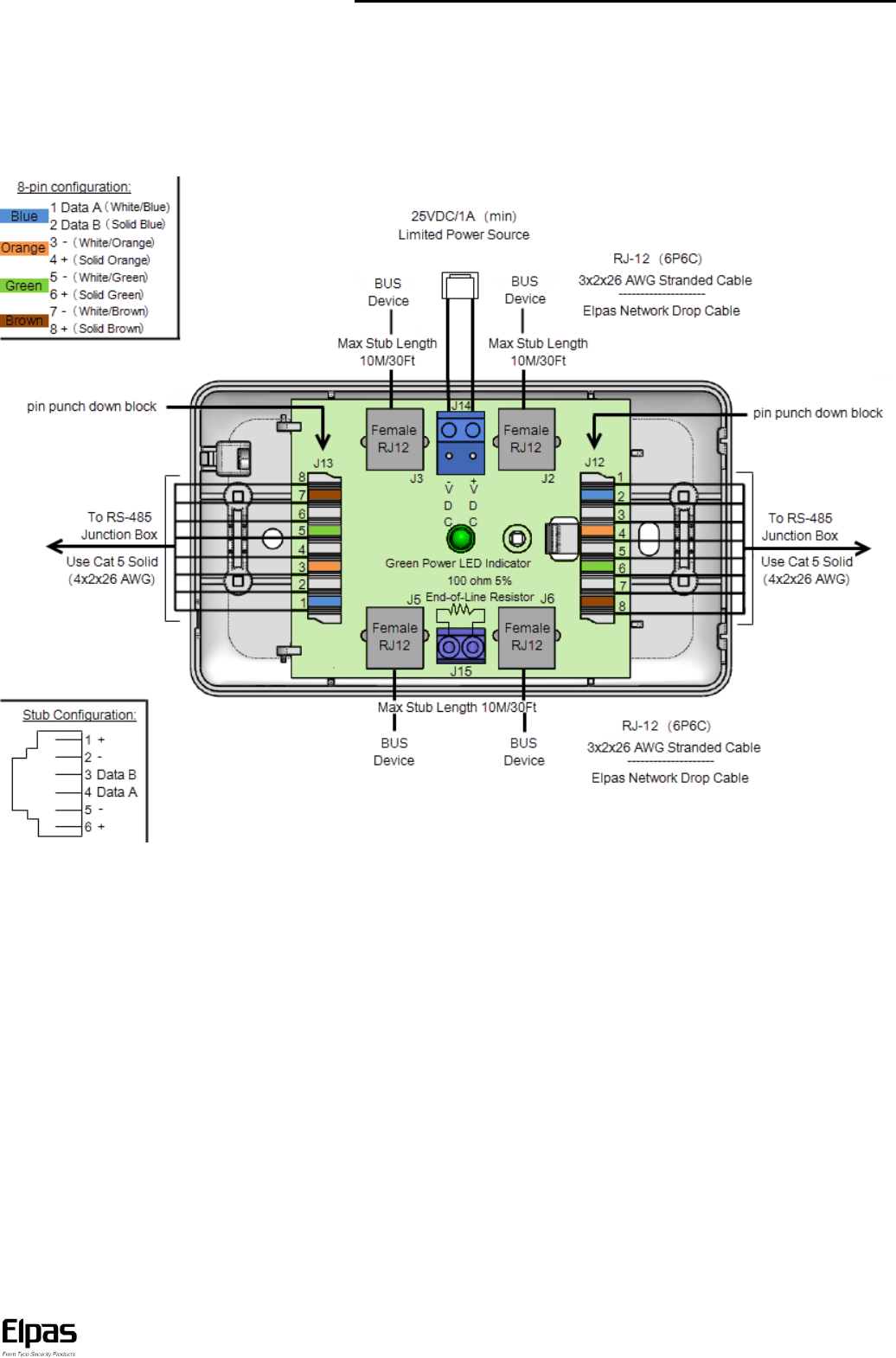
RS-485 BUS/Stub Topology
The RS-485 BUS MUST BE wired using a BUS/Stub topology where the BUS Master (a RF IP Reader or an ELC Controller) is connected
anywhere along the BUS. The topology supports data transmission between the BUS Master and up to 15 Elpas BUS Devices (such as RF or IR
Readers; LF Beacons primary & secondary), Elpas Display Panels and 6x6 I/O Modules using Elpas RS-485 Junction Boxes (P/N: 5-JBA00485).
IMPORTANT NOTE: Only 1 RF IP Reader/ELC Controller and up to 7 RF BUS Readers may coexist together on a single BUS.
200M/650Ft: Max. BUS length 10M/30Ft: Max. Stub length 100 Ohm Termination: Required each end of the BUS.
Recommended Cable/Power Supply Types:
BUS Backbone:
CAT5 solid (4x2x26AWG).
Power: Three twisted pairs
(six conductors) between junction boxes.
Data: One twisted pair (two conductors) between junction boxes.
Power: 16 to 28 VDC/2.5A Limited.
Note: For UL installations use only UL 294 (ALVY) compliant power supplies (see page 4 for details).

Proximity BUS Reader – Installation Guide
www.elpas.com
Page 4 of 6
V10/March 2014
Electrical Specifications
Frequency
Low frequency electromagnetic field (125 KHz)
ISO Card Standard
EM 4100
*Read Range
Up to 10 cm/4.0 inches (actual range depends on the proximity card or tag)
RS-485 BUS
230Kbit/sec
Device Supervision
Lost Away, Low Voltage, RS-485 BUS Communication Problem
Red LED Indicator
Unregistered in Eiris/ELC Programmer - Flashes once/second
Power up/RS-485 Communication Loss - Flashes once/second
Status LED
Software configurable
Inputs/Output
Two dry contact analog inputs (N.O.) One dry contact open collector digital output (up to 100mA)
Input Supervision
4 Levels (Open, Closed, Line Short, Line Cut) using optional Elpas End-of-Line Terminator
(Elpas End Of Line Terminators have not been evaluated for use in UL Applications)
Power Requirements
12–28VDC, 48mA @ 24VDC
General Specifications
Construction
White polycarbonate plastic (IP-67)
Device Interfaces
RS-485 Bus & Power: 2 meter/6.5ft in length, 6-wire AWG 26 cable with male RJ-11 (6P6C) connector
Input/Output : 2 meter 2 meter/6.5ft in length, 4-wire AWG 22 cable with ends
Dimensions (H x W x D)
116 x 70 x 16.8mm…(4.5 x 2.76 x 1.62 inches)
Weight
121.5 grams (4.3 ounces)
Operating Environment
Temp: -20°C to 50°C (-4°F to 122°F)…...Humidity: 20% to 100% non-condensing
Minimum Distance
Between Readers
30cm/ 12 inches
Management software
Eiris 4.7.1 (or higher) Software
*Actual read range depends on card/tag type, electrical environment and proximity to metal. Specifications are subject to change without notice.
Selected Compatible Accessories
Part Number
Description
3-6302-2
White proximity reader replacement cover (8 units)
3-6317-0
RDR-BACK, mounting spacer for metal surfaces
5-IOX00001
End-of-Line Terminator for Elpas & AXS Inputs (5 units)
5-JBA00485
RS-485 Junction Box, 4 RJ11 Ports
5-ERS02800
P60 Power Supply, 24VDC/2.2A

Proximity BUS Reader – Installation Guide
www.elpas.com
Page 5 of 6
V10/March 2014
UL 294 Compliance Installations
For all Elpas UL 294 compliant installations, the following requirements must be met:
UL installations are Controller based only and do not include an Eiris Server.
Elpas Fixed Infrastructure Products (except for Outdoor RF Readers) can only be installed in interior building locations only that do not
exceed the following environmental conditions:
o Temp: 0°C to 49°C (32°F to 120°F)
o Humidity: 85% non-condensing
Only 24VDC, UL 294 (ALVY) compliant power supplies such as Altronix model AL600ULPD4 can be used to power Elpas Infrastructure
Products
Note: All circuits must be power limited.
Elpas Outdoor RF Readers (Elpas PNs: 5-RFB00433-6 and 5-ELC00433-4) can only be installed in exterior building locations that do not
exceed the following environmental conditions:
o Temp: -35°C to 66°C (-31°F to 151°F)
o Humidity: 20% to 95% non-condensing
Only UL 294 compliant products may be connected to the outputs of any Elpas infrastructure device and may not be used for
”Burglary Applications”.
Limitations
Elpas Healthcare applications which are designed for hospitals assisted living and nursing care facilities for the protection of staff personnel,
patients or residents are not UL 294 compliant.
Specific Conditions
Elpas End-of-the Line Terminators (Elpas P/N: 5-IOX00001) are not evaluated for use in UL 294 Compliant Installations by Underwriters
Laboratories. Therefore, supervised inputs are for non UL applications only.
High-Power LF Beacons need to be powered locally and should not share the same power supply with any other Elpas Fixed
Infrastructure Product.
Note: Applies to the following Elpas P/Ns: 5-RLF00001-3, 5-RLF00001-31 and 5-RLF00001-32.
To ensure RF detection reliability the read range installation grids for all Local Controllers and RF Readers need to be designed so that
received messages from the Active RFID Tag does not fall below a RSSI Value of 121 (-90dBm).
Note: Applies to the following Elpas P/Ns: 5-RFB00433, 5-RFB00433-1, 5-RFB10433-2, 5-RFB10433-5,5-RFB00433-6, 5-ELC00433-1, 5-ELC10433-2,
5-ELC10433-3 and 5-ELC00433-4.

Proximity BUS Reader – Installation Guide
Page 6 of 6
V10/March 2014
W.E.E.E. Product Recycling Declaration
For information regarding the recycling of this product you must contact the company from which you orignially purchased it.
If you are discarding this product and not returning it for repair then you must ensure that it is returned as identified by your supplier.
This product is not to be thrown away with everyday waste.
Directive 2002/96/EC Waste Electrical and Electronic Equipment.
Regulatory
EU Declaration of Conformity
This equipment is in compliance with the essential requirements and other relevant provisions of Directive 1999/5/EC.
FCC & IC Compliance Standards
This device (FCC #:04X5-LFA00125 and IC #:1467G-5LFA00125) complies with
FCC Rules Part 15 and with industry Canada license exempt RSS.
Operation is subject to the following two conditions:
(1) This device may not cause harmful interference, and
(2) This device must accept any interference received, or that may cause
undesired operation.
For industry Canada: Le présent appareil est conforme aux CNR d'Industrie
Canada applicables aux appareils radio exempts de licence. L'exploitation est
autorisée aux deux conditions suivantes : (1) l'appareil ne doit pas produire de
brouillage, et (2) l'utilisateur de l'appareil doit accepter tout brouillage
radioélectrique subi, même si le brouillage est susceptible d'en compromettre le
fonctionnement.
Note: This equipment has been tested and found to comply with the limits for a
Class B digital device, pursuant to part 15 of the FCC Rules. These limits are
designed to provide reasonable protection against harmful interface in a
residential installation. This equipment generates; uses and can radiate radio
frequency energy and, if not installed and used in accordance with the
instructions, may cause harmful interference to radio communications.
However, there is no guarantee that interference will not occur in a particular
installation. If this equipment does cause harmful interference to radio or
television reception, which can be determined by turning the equipment off and
on, the user is encouraged to try to correct the interference by one or more of
the following measures:
Reorient or relocate the receiving antenna.
Increase the separation between the equipment and receiver.
Connect the equipment into an outlet on a circuit different from that to
which the receiver is connected.
Consult the dealer or an experienced radio/TV technician for help.
Changes or modifications to this equipment not expressly approved by the party
responsible for compliance (Elpas Solutions Ltd.) could void the user’s authority
to operate the equipment.
Company Contact
Elpas, Inc.
Westford, Massachusetts (USA) -Tel: 1-800-223-0020
.
Product Warranty
Elpas Solutions, Ltd. (the Company), and its affiliates, warrants its products
(hereinafter referred to as "the Product”) to be free of defects in materials and
workmanship under normal operating conditions and use for a period of one year
from the date of shipment by Elpas. The Company’s obligations shall be limited
within the warranty period, at its option, to repair or to replace the defective Product
or any defective component or part thereof. To exercise this warranty, the product
must be returned to the manufacturer freight prepaid and insured.
This warranty does not apply to repairs or replacement caused by improper
installation, Product misuse, failure to follow installation or operating instructions,
alteration, abuse, accident, tampering, repair by anyone other than Elpas, external
causes, and failure to perform required preventive maintenance. This warranty also
does not apply to any products, accessories, or attachments used in conjunction with
the Product, including batteries, which shall be covered solely by their own
warranties, if any. Elpas shall not be liable for any damage or loss whatsoever,
whether directly, indirectly, incidentally, consequentially or otherwise, resulting from
a malfunction of the Product due to products, accessories, or attachments of others,
including batteries, used in conjunction with the Product.
ELPAS MAKES NO EXPRESS WARRANTIES EXCEPT THOSE STATED IN THIS
STATEMENT. ELPAS DISCLAIMS ALL OTHER WARRANTIES, EXPRESS OR
IMPLIED, INCLUDING WITHOUT LIMITATION IMPLIED WARRANTIES OF
MERCHANTABILITY AND FITNESS FOR A PARTICULAR PURPOSE. ELPAS’S
SOLE RESPONSIBILITY FOR WARRANTY CLAIMS IS LIMITED TO REPAIR OR
TO REPLACE AS SET FORTH IN THIS STATEMENT.
Elpas shall have no liability for any death, personal injury, property damage, or other
loss whether direct, indirect, incidental, consequential, or otherwise, based on a
claim that the Product failed to function. However, if Elpas is held liable, whether
directly or indirectly, for any loss or damage arising under this limited warranty or
otherwise, regardless of cause or origin, the company's maximum liability shall be
limited to the purchase price of the Product, which shall be fixed as liquidated
damages and not as a penalty, and shall be the complete and exclusive liability of
Elpas.
Elpas shall not, under any circumstances whatsoever, be liable for any inaccuracy,
error of judgment, default, or negligence of Elpas, its employees, officers, agents, or
any other party, or of the purchaser or user, arising from any assistance or
communication of any kind regarding the configuration, design, installation, or
creation of security system involving the Product, that being the responsibility of the
purchaser or user. If Elpas is unable to make such repair or replacement, the
company’s entire liability shall be limited to the cost of a reasonable substitute
product. Elpas shall not be responsible for any dismantling, installation,
reinstallation, purchasing, shipping, insurance, or any similar charges.
Elpas shall have no liability for any damages, including without limitation, any direct,
indirect, incidental, special, or consequential damages, expenses, costs, profits, lost
savings or earnings, or other damages arising out of the use of the Product or the
removal, installation, reinstallation, repair or replacement of the Product or any
related events. In the event that there is any liability against Elpas, such liability shall
be limited to the purchase price of the Product which amount shall be fixed as
liquidated damages.
The purchaser and user understand that this Product may be compromised or
circumvented by intentional acts; that the Product will not in all cases prevent death,
personal injury, property damage, or other loss resulting from burglary, robbery, fire
or other causes; and that the Product will not in all cases provide adequate warning
or protection. The purchaser and user also understand that a properly installed and
maintained alarm may reduce the risk of events such as burglary, robbery, and fire
without warning, but it is not insurance or a guarantee that such events will not occur
or that there will be no death, personal injury, property damage, or other loss as a
result of such events.
By purchasing the Product, the purchaser and user shall defend, indemnify and hold
Elpas, its officers, directors, affiliates, subsidiaries, agents, servants, employees, and
authorized representatives harmless from and against any and all claims, suits,
costs, damages, and judgments incurred, claimed, or sustained whether for death,
personal injury, property damage, or otherwise, because of or in any way related to
the configuration, design, installation, or creation of a security system involving the
Product, and the use, sale, distribution, and installation of the Product, including
payment of any and all attorney’s fees, costs, and expenses incurred as a result of
any such events.
The purchaser or user should follow the Product installation and operation
instructions and test the Product and the entire system at least once each week. For
various reasons, including but not limited to changes in environmental conditions,
electric, electronic, or electromagnetic disruptions, and tampering, the Product may
not perform as expected. The purchaser and user are advised to take all necessary
precautions for the protection and safety of persons and property.
This statement provides certain legal rights. Other rights may vary by state or
country. Under certain circumstances, some states or countries may not allow
exclusion or limitation of incidental or consequential damages or implied warranties,
so the above exclusions may not apply under those circumstances and in those
states or countries.
Elpas reserves the right to modify this statement at any time, in its sole discretion
without notice to any purchaser or user. However, this statement shall not be
modified or varied except by Elpas in writing, and Elpas does not authorize any
single individual to act on its behalf to modify or vary this statement.
Any questions about this statement should be directed to Elpas.