Elpas Solutions 5-PBA00433 Active Identity Badge User Manual
Elpas Solutions Ltd. Active Identity Badge Users Manual
Users Manual

Page 1 of 3
V11.0 June 08
Active Identity Badge
User Guide – P/Ns: 5-PBA00433, 5-PBA00433-1, 5-PBA00433-2
5-PBA00433-3 and 5-PBA00880
Elpas
Active RFID Visibility Solutions
Introduction
The Elpas Active Identity Badge is
an ultra-low power, unified, long-
range active Radio Frequency
(RFID) and Infrared device.
Designed to resemble an industry-
standard photo ID badge, the
device is intended primarily for
protecting those staff members
and lone workers most at risk from
patient violence and aggression in
both interior and/or exterior areas.
The unique form factor of the badge makes it usable as a clip-on
photo ID personnel badge. Or, when inserted into its matching card
holder (sold separately) the device may be bundled with any
standard credit-card size access control card; and user worn either
horizontally (landscape format) or vertically (portrait format).
The badge's, dual technology
transmitter continuously emits, low-
power UHF (433.92MHz) long-
distance beacon type omni-
directional radio frequency (RF)
transmissions plus optional infra-red
(IR) messaging for indoor tracking
to sub-room level precision.
The Active Identity Badge features two one-touch fully customizable
emergency/duress signaling buttons for ensuring complete, around-
the-clock staff and visitor supervision. The badge’s onboard
magnetic low frequency (LF) receiver (125 KHz) also adds
chokepoint type area detection so whenever a badge wearer nears a
protected exit/entrance covered by an Elpas LF Exciter any number
of user definable alerts or alarms may be triggered. Optionally, the
badge is designed for use as an electronic proximity key for doors
protected by VisAccess Tag-In-A-Bag, AXS-10, AXS-100/200
systems or other third-party EM 4100 compliant or Wiegand 26-bit
compatible access control solutions.
Small in size (5cm/2in x 8.3cm/3.27in x 0.9cm/0.35in) and weight
(32g/1.2oz) the Active Identity Badge is housed in an epoxy potted,
IP66 rated, weatherproof black thermoplastic outer casing. Powered
by a single, replaceable lithium long life battery (five-year estimated
usage), the badge’s power efficient design ensures years of
maintenance free deployments in harsh indoor and outdoor
environments such as manufacturing operations, medical facilities or
maximum security correctional institutions.
Supported Event Transmissions
Active Identity Badges supports LF, Battery, Motion, Motionless, Exit from
LF and two discrete Button Press events; designated B1 and B2.
Each event is transmitted as a burst of 4 messages. Should 1 event
interrupt another, then the first event burst will end after a minimum of two
messages.
The entry to LF event messages contain the ID of the LF Exciter.
IMPORTANT: The badge does not support simultaneous press of B1 and
B2.
Technical Specifications
Radio Technology RF (433.92MHz) and LF (125KHz)
RF (Motion/Stationary) Every 10 seconds / 20 seconds
IR (Motion/Stationary) Every 4.5 seconds / 60 seconds
RF Transmission Rate
upon entry into LF area
4 IR/RF transmissions (each transmission @
2ms in duration), 0.5 seconds apart. Then
repeated at 2 seconds intervals.
RF Range 200 meters/ 656ft (360° coverage area)
LF Sampling
(Motion/Stationary) Every 500ms / 15 seconds
RF under LF Rate 2 secs; after 10 minutes returns to 10 secs
IR under LF Rate 10 seconds
LF Timeout Transmits 2 non-LF messages after not
hearing from LF for this amount of time
Time to Idle 10 seconds
Button Press/Release 4 IR/RF transmissions (each transmission
@ 2ms in duration), 400 ms apart
Power Source 3V/600mAh Lithium Battery, type: CR2450
Battery Life 5 years approximately
Low Battery Voltage 2.3 volts
Visual Indicator Red LED specifics button press and release
Badge ID Unique factory programmed
Proximity Specifications
Standard/Frequency EM 4100 compliant/ 125 kHz
Typical Working Range Up to 30cm (11.8 inches) - Actual range
depends on proximity reader type
General Specifications
Construction Black, polymer plastic
Dimensions (H x W x D) 5.0 x 8.3 x 0.9cm (2.0 x 3.27 x 0.35 inches)
Weight (assembled) 32 grams (1.128 ounces)
Temp. and Humidity -10°-0°C (14-59°F),100% non-condensing
Housing IP66 water rated enclosure
Remote Management EIRIS 4.6 or higher enterprise software
Standards
FCC Part 15.231 Level C, FCC ID#: GSA-
BTC00433 (433.92 MHz) and EC approvals
pending
Warranty One year limited warranty
All specifications are subject to change without notice
Ordering Information
Part # Description
5-PBA00433 Active Identity Badge, WP, IR/RF/LF, 433MHz, 4.5/10/60
5-PBA00433-1 Active Identity Badge, WP, RF/LF, 433MHz, 10/60
5-PBA00433-2 Active Identity Badge, WP, IR/RF/LF/Prox,433MHz,
4.5/10/60
5-PBA00433-3 Active Identity Badge, WP, RF, 433MHz, 10/60
5-PBA00880 Active Identity Badge, WP, IR, 433MHz, 4.5/60
Part # Accessories
5-PBA90001 Personnel Identity Badge - Clip Attachment (25 pcs)
5-PBA90002 Open Front Card Holder, Horizontal/Vertical, (5 pcs)
5-PBA90003 3V/600mAh Lithium Battery, CR2450 (25 pcs)
5-PBA90004 Personnel Identity Badge - Label Covers (25 pcs)
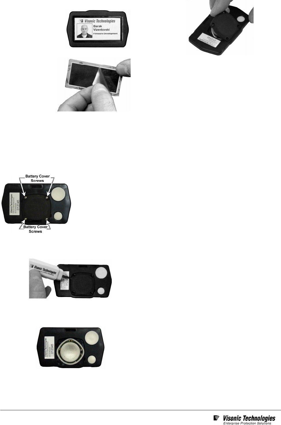
Badge Activation Prior to Initial Usage
1. Orient the badge
back-cover side up.
Then press & hold
down the larger of two
emergency call
buttons for at least 6
seconds
2. If the activation process
was successful the red
LED on the front of the
badge will illuminate
for about 6 seconds.
Page 2 of 3
V11.0 June 08
Attaching a Paper Photo ID to the Badge
1. Ensure that the photo ID
paper label is trimmed
properly so that it lies
flatly (picture/text side up)
in the recessed
area on the front of
the badge.
2. Peel off the clear
protective layer on
the font and rear of
the label cover
(P/T: 5-PBA90004).
3. Finally, remove the label cover’s adhesive backing and carefully
place it (adhesive edge down) onto the badge so that it neatly holds
the paper label correctly in place.
Battery Replacement
1. Place the badge back cover side up on a clear dry level surface.
Using a Phillips-type screwdriver that fits the battery cover
screws, unscrew the 4 screws that holds the battery cover in
place.
2. Separate the battery cover from the back of the badge by
inserting a small screw driver into either of the square slots
adjacent to the battery cover. Gently lever the screw driver
outwards until the battery cover releases from the badge.
3. Remove the worn-out battery from the badge and dispose of it
according to manufacture’s instructions.
4. Insert a new battery (P/T: 5-PBA90003) into the compartment,
ensuring that that the positive (+) side of the battery faces up.
5. Align the battery cover so that its flat edge fits correctly into the
badge’s back cover prior to seating the cover into place.
6. Once the battery cover is in place, tighten its 4 screws
into place.
Standards Compliance This device complies with Part 15 of the
FCC Rules; and its operation is subject to the following two
conditions:
• This device may not cause harmful interference
• This device must accept any interference received, including
interference that may cause undesired operation.
For a Class B digital device or peripheral, the instructions furnished
the user shall include the following or similar statement, placed in a
prominent location in the text of the manual:
NOTE: This equipment has been tested and found to comply with
the limits for a Class B digital device, pursuant to Part 15 of the FCC
Rules. These limits are designed to provide reasonable protection
against harmful interference in a residential installation. This
equipment generates uses and can radiate radio frequency energy
and, if not installed and used in accordance with the instructions,
may cause harmful interference to radio communications. However,
there is no guarantee that interference will not occur in a particular
installation.
If this equipment does cause harmful interference to radio or
television reception, which can be determined by turning the
equipment off and on, the user is encouraged to try to correct the
interference by one or more of the following measures:
• Reorient or relocate the receiving antenna.
• Increase the separation between the equipment and receiver.
Connect the equipment into an outlet on a circuit different from
that to which the receiver is connected.
• Consult the dealer or an experienced radio/TV technician for
help.
Warning! Changes or modifications to this equipment not approved
by the party responsible for compliance (Visonic Technologies Ltd.)
could void the user’s authority to operate the equipment.
Page 3 of 3
V11.0 June 08
W.E.E.E. Product Recycling Declaration
For information regarding the recycling of this product you must contact the company from which you orignially purchased
it. If you are discarding this product and not returning it for repair then you must ensure that it is returned as identified by your
supplier. This product is not to be thrown away with everyday waste.
Directive 2002/96/EC Waste Electrical and Electronic Equipment.
Product Warranty
Visonic Technologies Ltd. (VT or the Company), and its affiliates,
warrants its products (hereinafter referred to as "the Product”) to be free
of defects in materials and workmanship under normal operating
conditions and use for a period of one year from the date of shipment by
VT. The Company’s obligations shall be limited within the warranty
period, at its option, to repair or to replace the defective Product or any
defective component or part thereof. To exercise this warranty, the
product must be returned to the manufacturer freight prepaid and
insured.
This warranty does not apply to repairs or replacement caused by
improper installation, Product misuse, failure to follow installation or
operating instructions, alteration, abuse, accident, tampering, repair by
anyone other than VT, external causes, and failure to perform required
preventive maintenance. This warranty also does not apply to any
products, accessories, or attachments used in conjunction with the
Product, including batteries, which shall be covered solely by their own
warranties, if any. VT shall not be liable for any damage or loss
whatsoever, whether directly, indirectly, incidentally, consequentially or
otherwise, resulting from a malfunction of the Product due to products,
accessories, or attachments of others, including batteries, used in
conjunction with the Product.
VT MAKES NO EXPRESS WARRANTIES EXCEPT THOSE STATED IN
THIS STATEMENT. VT DISCLAIMS ALL OTHER WARRANTIES,
EXPRESS OR IMPLIED, INCLUDING WITHOUT LIMITATION IMPLIED
WARRANTIES OF MERCHANTABILITY AND FITNESS FOR A
PARTICULAR PURPOSE. VT’S SOLE RESPONSIBILITY FOR
WARRANTY CLAIMS IS LIMITED TO REPAIR OR TO REPLACE AS
SET FORTH IN THIS STATEMENT.
VT shall have no liability for any death, personal injury, property damage,
or other loss whether direct, indirect, incidental, consequential, or
otherwise, based on a claim that the Product failed to function. However,
if VT is held liable, whether directly or indirectly, for any loss or damage
arising under this limited warranty or otherwise, regardless of cause or
origin, VT's maximum liability shall be limited to the purchase price of
the Product, which shall be fixed as liquidated damages and not as a
penalty, and shall be the complete and exclusive liability of VT.
VT shall not, under any circumstances whatsoever, be liable for any
inaccuracy, error of judgment, default, or negligence of VT, its
employees, officers, agents, or any other party, or of the purchaser or
user, arising from any assistance or communication of any kind
regarding the configuration, design, installation, or creation of security
system involving the Product, that being the responsibility of the
purchaser or user.
If VT is unable to make such repair or replacement, VT’s entire liability
shall be limited to the cost of a reasonable substitute product. VT shall
not be responsible for any dismantling, installation, reinstallation,
purchasing, shipping, insurance, or any similar charges.
VT shall have no liability for any damages, including without limitation,
any direct, indirect, incidental, special, or consequential damages,
expenses, costs, profits, lost savings or earnings, or other damages
arising out of the use of the Product or the removal, installation,
reinstallation, repair or replacement of the Product or any related events.
In the event that there is any liability against VT, such liability shall be
limited to the purchase price of the Product which amount shall be fixed
as liquidated damages.
The purchaser and user understand that this Product may be
compromised or circumvented by intentional acts; that the Product will
not in all cases prevent death, personal injury, property damage, or
other loss resulting from burglary, robbery, fire or other causes; and that
the Product will not in all cases provide adequate warning or protection.
The purchaser and user also understand that a properly installed and
maintained alarm may reduce the risk of events such as burglary,
robbery, and fire without warning, but it is not insurance or a guarantee
that such events will not occur or that there will be no death, personal
injury, property damage, or other loss as a result of such events.
By purchasing the Product, the purchaser and user shall defend,
indemnify and hold VT, its officers, directors, affiliates, subsidiaries,
agents, servants, employees, and authorized representatives harmless
from and against any and all claims, suits, costs, damages, and
judgments incurred, claimed, or sustained whether for death, personal
injury, property damage, or otherwise, because of or in any way related
to the configuration, design, installation, or creation of a security system
involving the Product, and the use, sale, distribution, and installation of
the Product, including payment of any and all attorney’s fees, costs, and
expenses incurred as a result of any such events.
The purchaser or user should follow the Product installation and
operation instructions and test the Product and the entire system at
least once each week. For various reasons, including but not limited to
changes in environmental conditions, electric, electronic, or
electromagnetic disruptions, and tampering, the Product may not
perform as expected. The purchaser and user are advised to take all
necessary precautions for the protection and safety of persons and
property.
This statement provides certain legal rights. Other rights may vary by
state or country. Under certain circumstances, some states or countries
may not allow exclusion or limitation of incidental or consequential
damages or implied warranties, so the above exclusions may not apply
under those circumstances and in those states or countries.
VT reserves the right to modify this statement at any time, in its sole
discretion without notice to any purchaser or user. However, this
statement shall not be modified or varied except by VT in writing, and
VT does not authorize any single individual to act on its behalf to modify
or vary this statement .
Any questions about this statement should be directed to VT. 3/0
VT World Headquarters * Tel Aviv, Israel * Tel: + 972 3 768-1400 * support@visonictech.com
VT Americas * Bloomfield, CT (USA) * Tel: 1-800-223-0020 * vta_support@visonictech.com
VT United Kingdom * Beckenham Kent BR3 90BF, U.K. * Tel: + 44-870-730-0840 * vtuk_support@ visonictech.com
Visonic GmbH * D-40215 Düsseldorf, Germany * Tel: + 49-0-211-600-696-0 * support@ visonictech.de
Manufactured
in Israel
Additional information may be found at: www.visonictech.com