Elpas Solutions 5-RRB00880 ELPAS IR READER RS-485 User Manual
Elpas Solutions Ltd. ELPAS IR READER RS-485 Users Manual
Users Manual
Gen-2 IR Location Reader
Wiring Guide - For P/N: 5-IRB00880 Elpas
Active RFID/RTLS Solutions
Page 1 of 2
D-302086_V5/Aug. 09
Introduction
This wiring guide provides basic instructions for common installation scenarios. For advanced functionality, this document should
also be used in conjunction with the Elpas Gen-2 IR Reader Installation & Configuration Guide.
Download from the EIRIS Software Download Page (http://www.visonictech.com/Eiris.html) of the VT Website the Elpas 4.6.3
Installer file, which contains all the necessary software extensions and updates for enrolling and configuring Gen-2 IR Location
Readers into existing or new EIRIS installations. It is highly recommended that you ensure that the EIRIS installation on the host
machine has been properly updated before wiring the readers.
Note: VT is not responsible for any radio or TV interference caused by unauthorized modifications to this equipment. Such modifications could void the
user’s authority to operate the equipment.
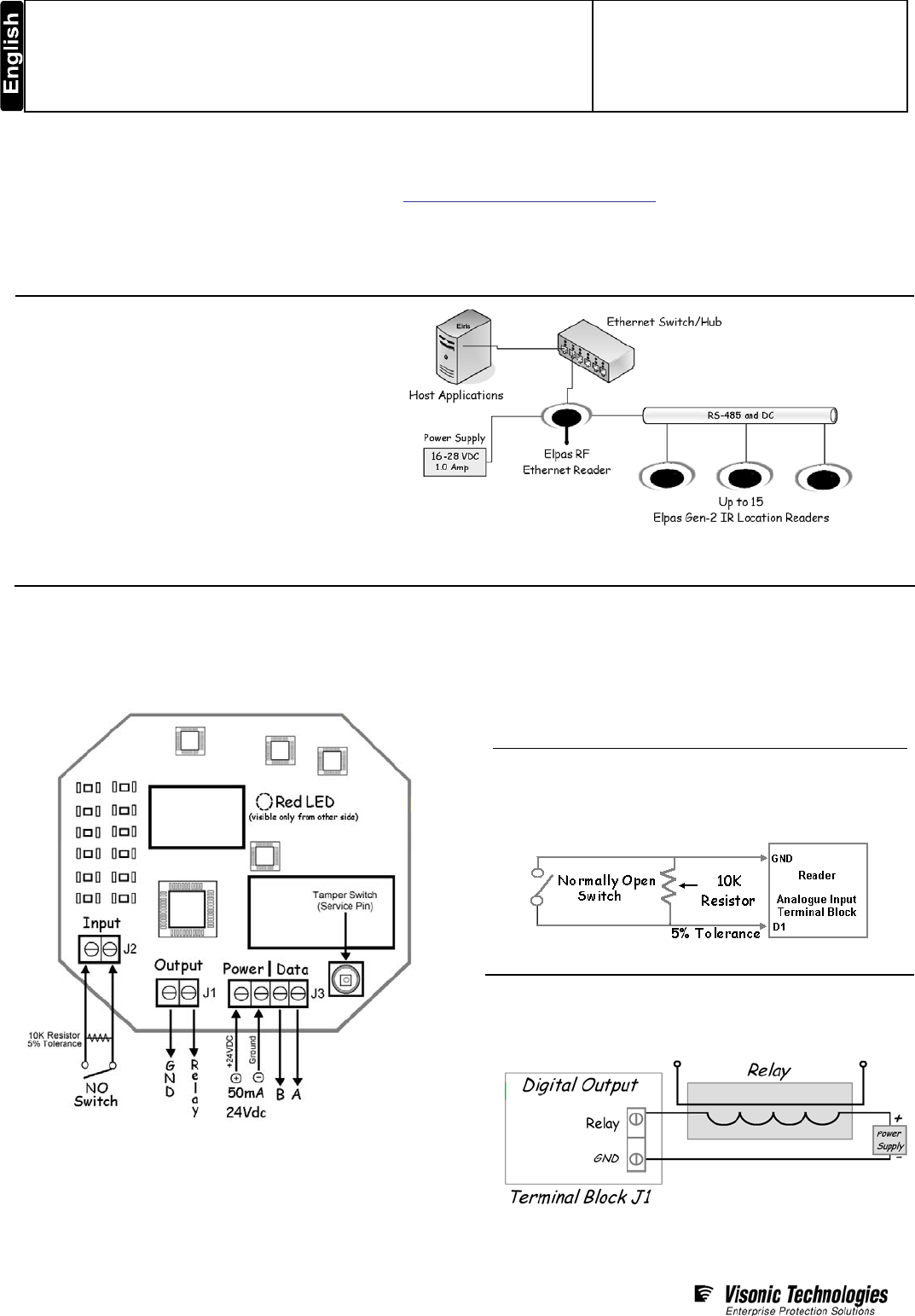
Product Description
The Gen-2 IR Location Reader is a
supervised; fixed receiving device that detects
and relays ‘State’ and sub-room ‘Location’
data from Elpas Active RFID IR-enabled tags
to host applications over wired or wireless
Ethernet/Wi-Fi networks in real-time.
The reader’s onboard I/O enables the local
monitoring of one general purpose analogue
input and control of one open-collector digital
switched device. The reader also supports
RS-485 data transmission to fourteen other
Elpas RS-485 BUS devices plus to one Elpas
RF Ethernet Reader.
FCC Compliance: PART 15, Sub-part B, Class B FCC ID: O4X5-IRB0088
CE Compliance: EN300220-1, EN300220-2, EN60950-1, ICES-003, CAN/CSA-CEI/ICE CISPR 22
IC Compliance: 1467G IRB00880
Circuit Board Terminal Blocks
The Gen-2 IR Location Reader has one analogue input (J2) and
one digital open-collector output (J1) located on the right-hand
side of the board. The reader also includes a four position color-
coded removable RS-485 terminal block (J3) for date and power
connections (see page 2 for details).
The Gen-2 IR Location Reader has a Service Pin/Tamper
Switch that generates service messages when pressed to aide
device registration. The Service Pin/Tamper Switch is also used
to indicate attempts to remove the device’s cover after the
device has been enrolled in EIRIS.
Power
Ensure that the Gen-2 IR Location Reader is connected to the
power source. Then switch off the device till you have wired the
I/O and the RS-485 BUS terminal blocks to prevent accidental
shorts or power spikes from causing damage to the reader.
Power Requirements: 100mA/24Vdc
Recommended Cable: CAT5 Stranded (4x2x26AWG)
Max Distance: Refer to wiring topologies on page 2
Analogue Input
The Gen-IR Location Reader is equipped with one general
purpose analogue input (Terminal Block J2). The input is a
two-wired supervised circuit for monitoring alarm detection
devices such as ultrasonic motion detectors and door contacts.
Recommended Cable: 22 AWG, unshielded/twisted pair
Digital Outputs
The Gen-IR Location Reader has a general purpose digital
output (Terminal Block J1) that provides open-collector
switching (up to 100mA, 28Vdc).
Recommended Cable: 22 AWG, unshielded/twisted pair
Elpas Gen-2 IR Location Reader – Wiring Guide
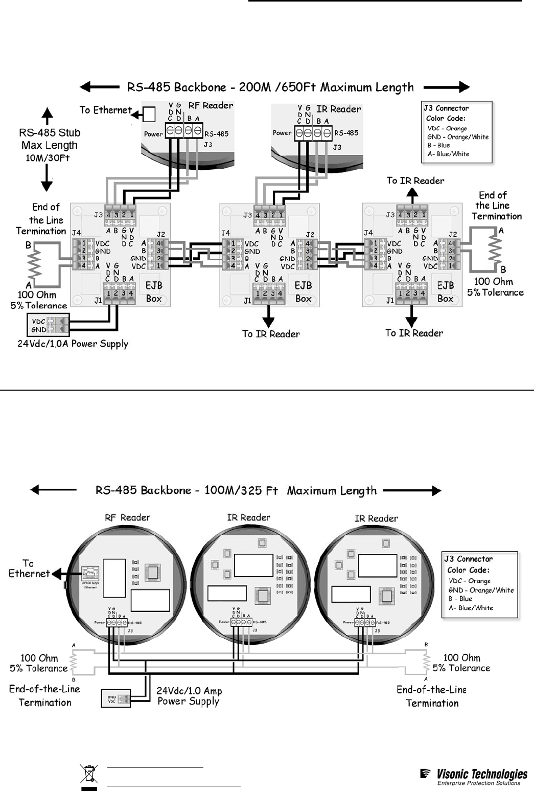
RS-485 BUS/Stub Topology
The Elpas-2 RS-485 BUS may be wired using a BUS/Stub topology using 4-port EJB boxes (P/N: 5-EJB00001). This topology
supports data transmission between 1 RF Ethernet Reader (BUS-Master) and up to 15 BUS Slaves (IR Readers, I/Os,
RDUs…etc). Additionally the reader may be connected at any location along the RS-485 data BUS.
200M/650Ft: Max. BUS length 10M/30Ft: Max. Stub length 100 Ohm Termination: Required each end of the BUS
Recommended Cable Type: CAT5 Stranded (4x2x26AWG)
For Power: Use three twisted pairs (six conductors) between EJBs Use one twisted pair (two conductors) between each EJB and Reader.
For Data: Use one-twisted pair (two conductors)
RS-485 Daisy Chain Topology
The Elpas-2 RS-485 BUS may be wired using a Daisy Chain topology. This configuration supports data transmission between
1 RF Ethernet Reader (BUS-Master) and up to 7 BUS Slaves (IR Readers, I/Os, RDUs...etc).
The RF Ethernet Reader may be connected at any location on the RS-485 data chain as long as the power supply is connected
to the power BUS in close proximity to the RF reader.
100M/325 Ft: Maximum cable length 100 Ohm Termination: Required at each end of the daisy chain
Recommended Cable Type: CAT5 Stranded (4x2x26AWG)
For Power: Use one twisted pair (two conductors) For Data: Use one-twisted pair (two conductors)
Page 2 of 27
D-302086_V5/Aug. 09
W.E.E.E. Product Recycling Declaration
For information regarding the recycling of this product you must contact the company from which you orignially purchased it.
If you are discarding this product and not returning it for repair then you must ensure that it is returned as identified by your supplier.
This product is not to be thrown away with everyday waste.
Directive 2002/96/EC Waste Electrical and Electronic Equipment.