Elster Solutions EA2W-I Sprean Spectrum Transmitter User Manual IL42 5016
Elster Solutions, LLC Sprean Spectrum Transmitter IL42 5016
UserManual.wiki
>
Elster Solutions
>
EA2W-I User Manual
>
User Manual
Contents
1.
final version - User manual
2.
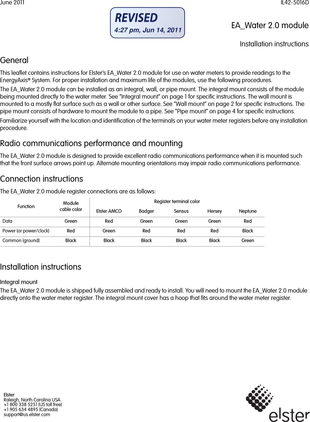
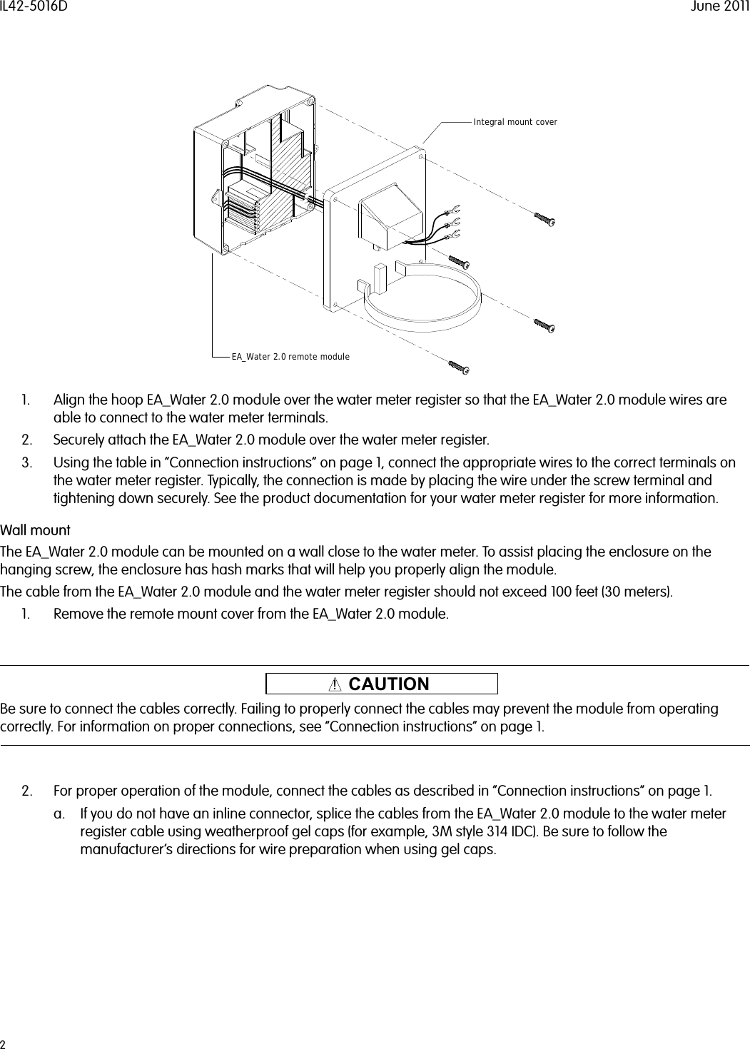
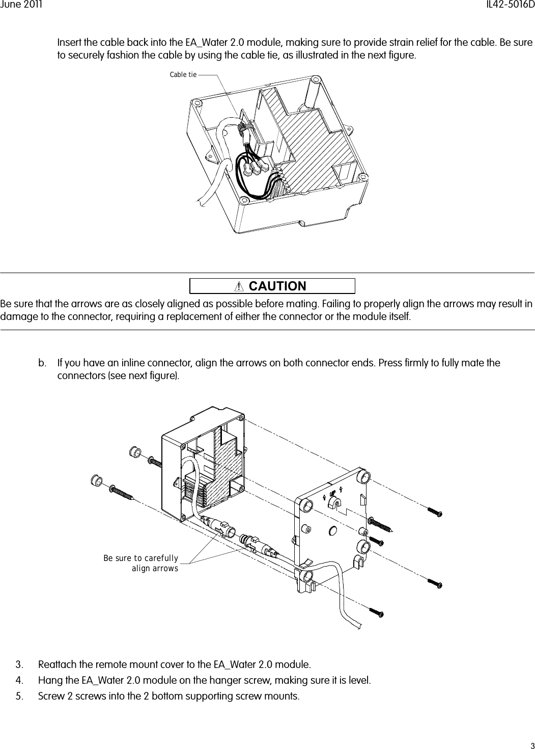
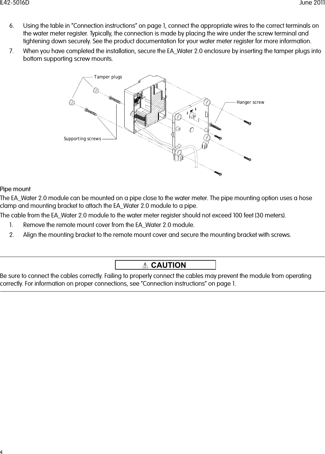
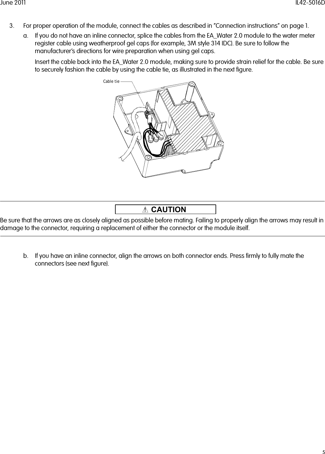
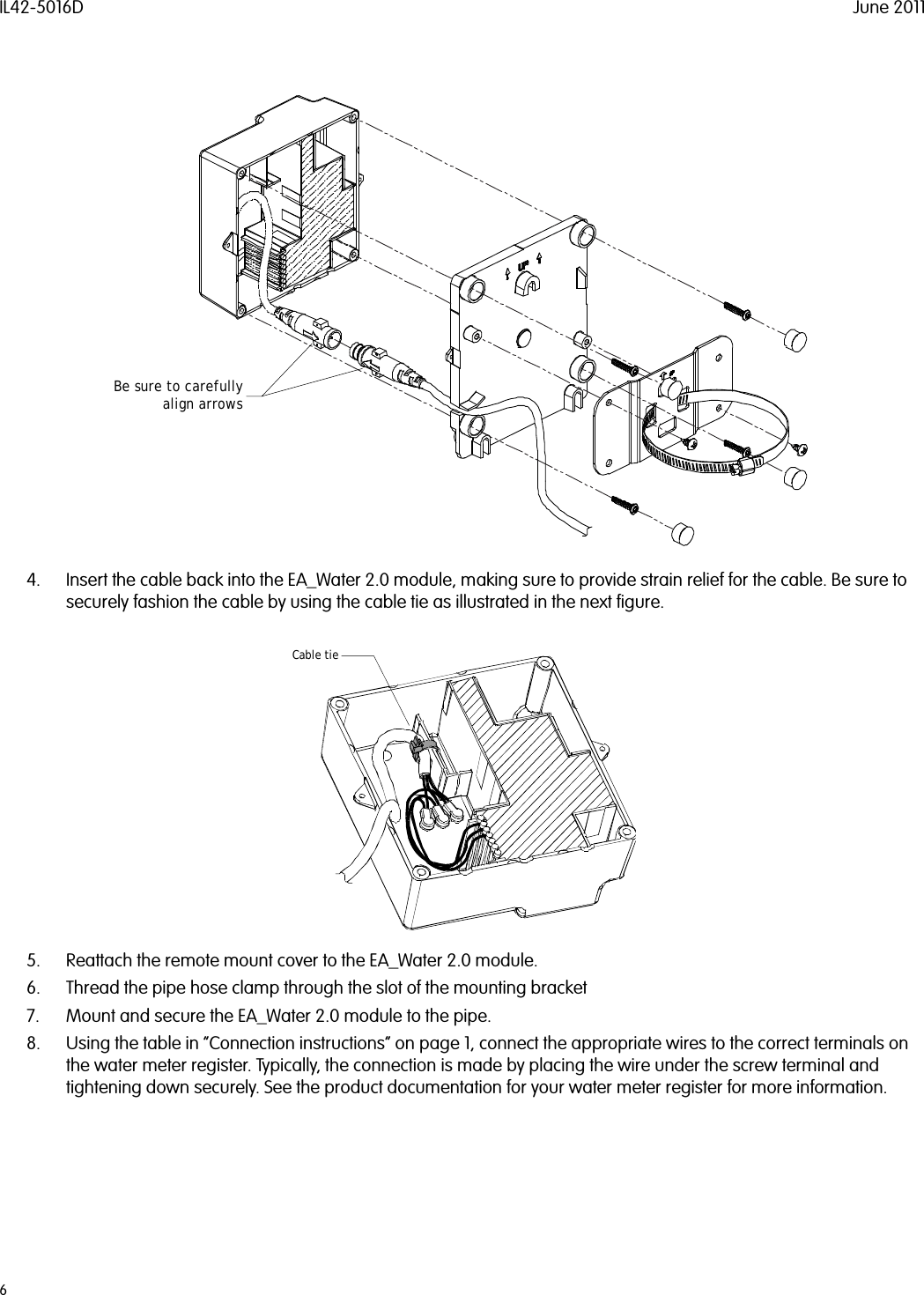
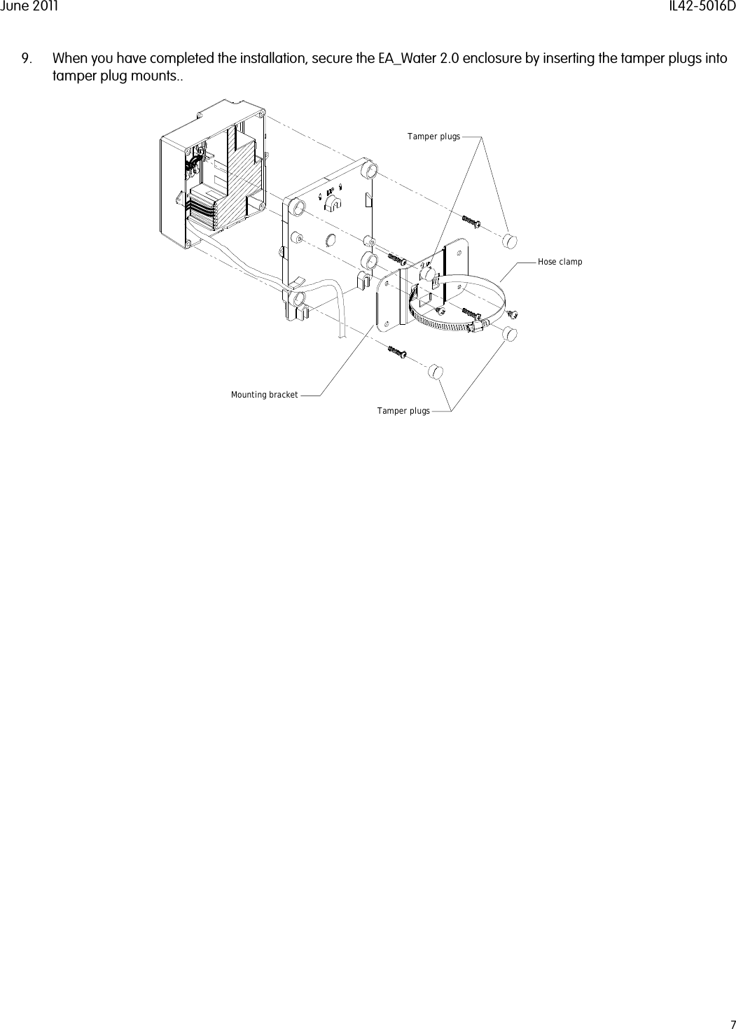
User Manual
User Manual
Navigation menu
Upload a User Manual
Namespaces
Wiki Guide
HTML
PDF
Info
Views
User Manual
Discussion / Help
Navigation