Elster Solutions EAGAS01 EnergyAxis Gas Module User Manual Manual
Elster Solutions, LLC EnergyAxis Gas Module Manual
UserManual.wiki
>
Elster Solutions
>
EAGAS01 User Manual
Manual
Navigation menu
Upload a User Manual
Namespaces
Wiki Guide
HTML
PDF
Info
Views
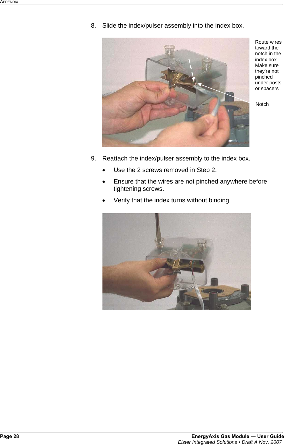
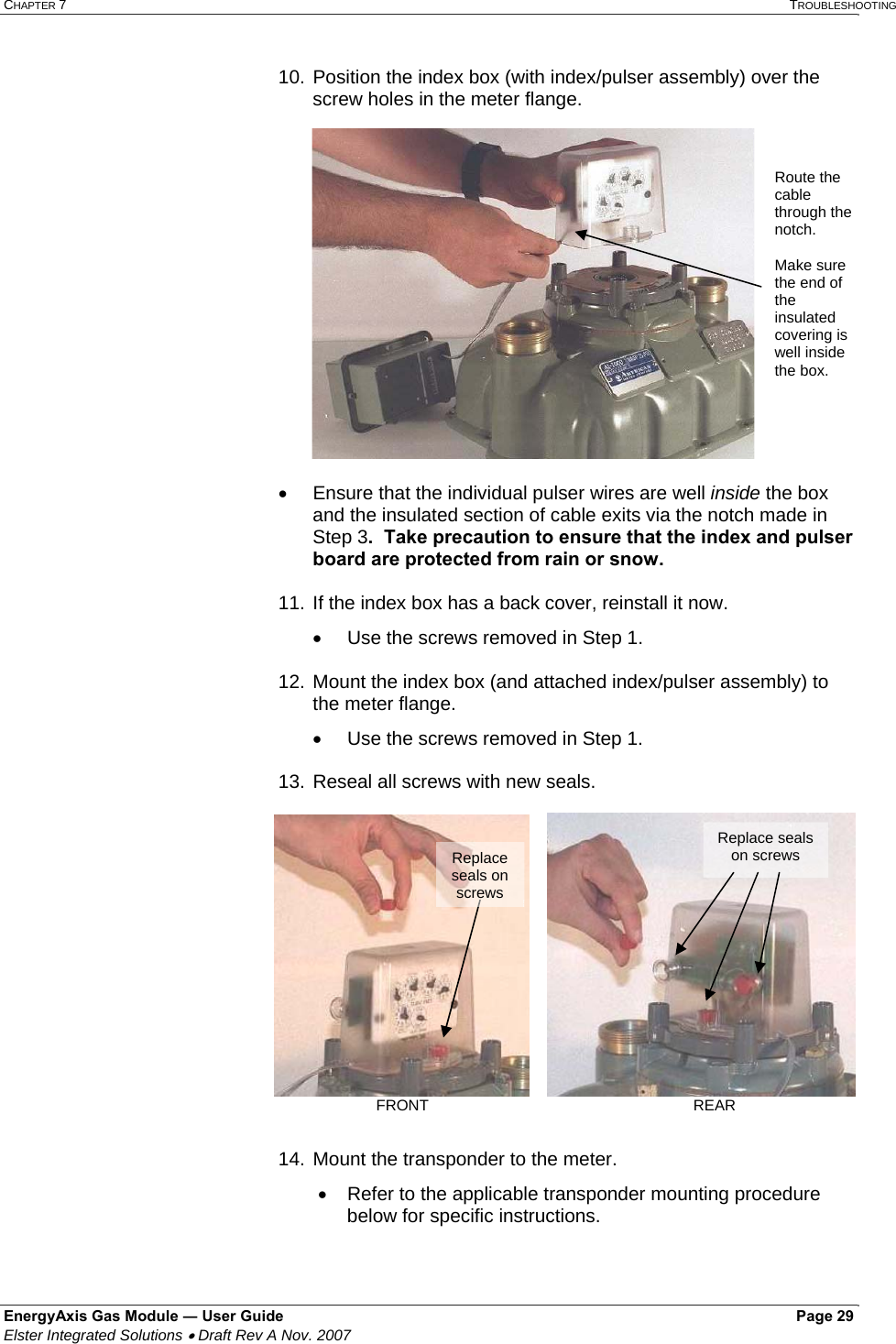
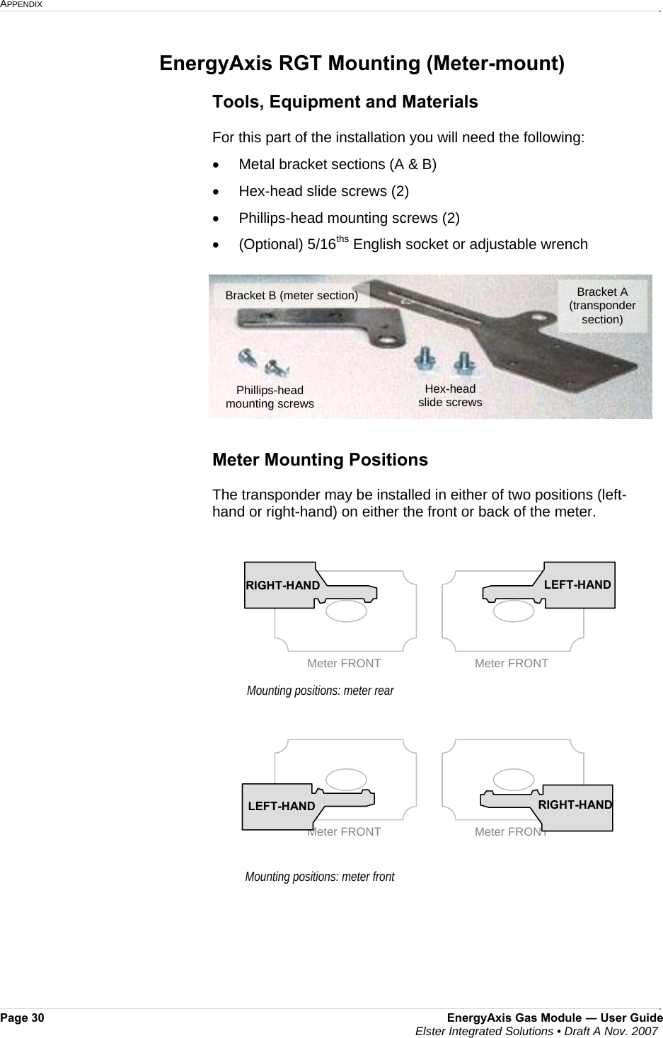
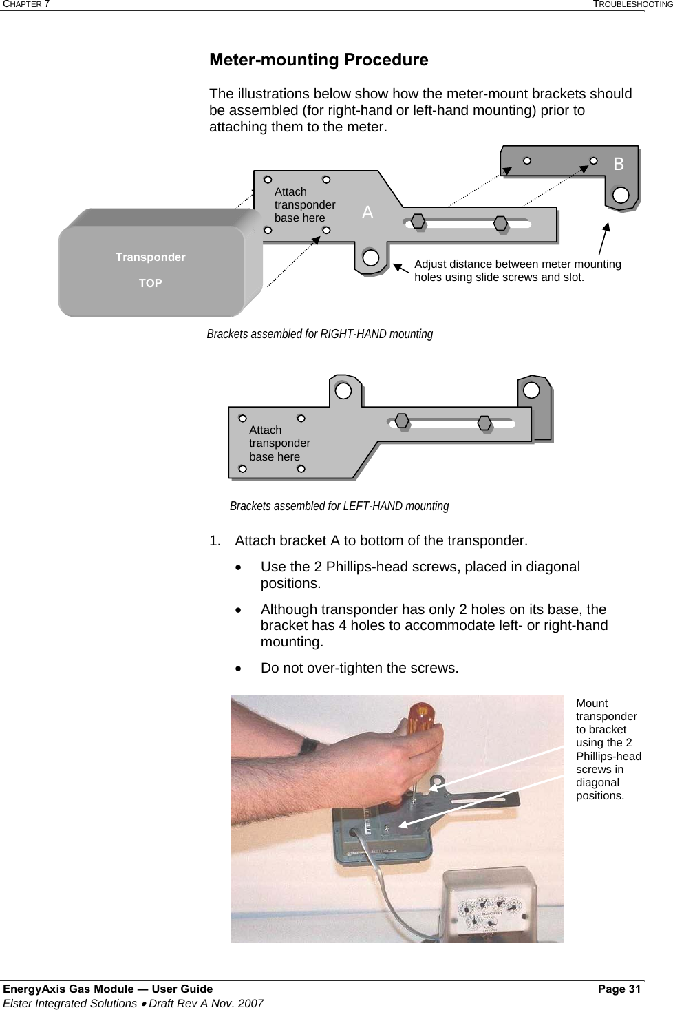
User Manual
Discussion / Help
Navigation