Elster Solutions EAGAS01 EnergyAxis Gas Module User Manual Manual
Elster Solutions, LLC EnergyAxis Gas Module Manual
Manual

U
U
US
S
SE
E
ER
R
R
G
G
GU
U
UI
I
ID
D
DE
E
E
E
En
ne
er
rg
gy
yA
Ax
xi
is
s
G
Ga
as
s
M
Mo
od
du
ul
le
e

TABLE OF CONTENTS
EnergyAxis Gas Module ― User Guide Page i
Elster Integrated Solutions
•
P/N 52870T010 Rev 3 March 2007
Copyright Acknowledgements
The contents of this document are the property of Elster Integrated
Solutions and are copyrighted. All rights reserved. Any
reproduction, in whole or in part, is strictly prohibited. For
additional copies of this document, please contact:
Elster Integrated Solutions
208 South Rogers Lane
Raleigh, NC 27610
Phone 919-250-5700 Fax 919-250-5439
The information contained herein has been carefully checked and
is believed to be accurate; however, no responsibility is assumed
for inaccuracies. Elster Integrated Solutions reserves the right to
make changes without prior notice. This document is not covered
by any warranty either expressed or implied. Any correction,
comments or additions to the contents of this document should be
directed to Elster Integrated Solutions at the above address.
Copyright 2003 Elster Integrated Solutions. Printed in USA.
EnergyAxis are trademarks of Elster Integrated Solutions. All rights
reserved.

Page ii EnergyAxis Gas Module ― User Guide
Elster Integrated Solutions • Draft Rev A Nov. 2007
FCC & Industry Canada Compliance
EnergyAxis Gas Module™ has been granted authorization as a low power
modular radio transmitter by the Federal Communications Commission
under 47 CFR Part 15.247 and by Industry Canada under RSS-GEN and
RSS-210. FCC ID: G8JEAGAS01. Industry Canada ID: 3599-EAGAS01.
The device transmits and receives in the frequency range 902.8 – 927.6
MHz. The device may also receive on 451.35 MHz.
The user of this device must maintain a distance of 20cm between the
device and any part of the human body, to comply with FCC RF exposure
requirements.
This device complies with FCC Part 15 & Industry Canada RSS-GEN/RSS-
210 rules. Operation is subject to the following conditions:
1. This device may not cause harmful interference, and
2. This device must accept any interference received, including
interference that may cause undesired operation.
This equipment has been tested and found to comply with the limits for a
Class B digital device, pursuant to Part 15 of the FCC Rules. These limits
are designed to provide reasonable protection against harmful interference
in a residential installation.
This equipment generates uses and radiates radio frequency energy, and if
not installed and used in accordance with the instructions, may cause
harmful interference to radio communications. However, there is no
guarantee that interference will not occur in a particular installation.
If this equipment does cause harmful interference to radio or television
reception, which can be determined by turning the equipment off and on,
the user is encouraged to try to correct the interference by one or more of
the following measures:
• Reorient or relocate the receiving antenna.
• Increase the separation distance between the equipment and receiver.
• Connect the equipment into an outlet on a circuit different from that to
which the receiver is connected (not applicable for the battery-powered
EnergyAxis Gas Module™).
• Consult the equipment dealer or an experienced radio/TV technician
for help.
WARNING! Changes or modifications not expressly approved by Elster
Integrated Solutions void the user’s authority to operate the
equipment.

TABLE OF CONTENTS
EnergyAxis Gas Module ― User Guide Page i
Elster Integrated Solutions
•
P/N 52870T010 Rev 3 March 2007
EnergyAxis Gas Module
USER GUIDE
Table of Contents
Chapter One.............................................................................................. 1
Introduction ......................................................................................................................................... 1
About this Document 1
Chapter Two..................................................................................................................................... 3
Automated Meter Reading Overview................................................................................................. 3
Basic AMI Components 3
EnergyAxis AMI System Overview 4
Chapter Three.................................................................................................................................. 5
EnergyAxis Direct Gas-meter Transponder Overview .................................................................... 5
EnergyAxis Direct Gas-meter Transponder and Components 6
How the EnergyAxis Direct Gas-meter Transponder Works 9
Specifications 10
Chapter Four................................................................................................................................... 11
EnergyAxis Direct Gas-meter Transponder Installation ............................................................... 11
Tools, Equipment and Materials 11
Preparation and Installation 12
Programming the EnergyAxis Direct Gas-meter Transponder 17
Chapter Five ................................................................................................................................... 19
EnergyAxis Remote Gas-meter Transponder Overview ............................................................... 19
How it Works 20
Features and Capabilities 20
EnergyAxis Remote Gas-meter Transponder Construction 20
Identifying the Components (Meter Mount) 22
Chapter Six ..................................................................................................................................... 23
EnergyAxis Remote Gas-meter Transponder Installation ............................................................ 23
Tools, Equipment and Materials 23
Pulser Installation (Meter-mount) 24
EnergyAxis RGT Mounting (Meter-mount) 30
EnergyAxis RGT Programming (All) 34
Appendix.......................................................................................................................................... 36
Pre-Divider 36
Pressure-Compensation Factor 36

Page ii EnergyAxis Gas Module ― User Guide
Elster Integrated Solutions • Draft Rev A Nov. 2007

CHAPTER 1 INTRODUCTION
EnergyAxis Gas Module ― User Guide Page 1
Elster Integrated Solutions
•
Draft Rev A Nov. 2007
Chapter One
Introduction
The EnergyAxis Gas Module is the heart of Elster Integrated
Solutions’ portfolio of products for automated metering infrastructure
(AMI).
About this Document
The EnergyAxis Gas Module User Guide provides instructions for
installing and troubleshooting transponders. It also includes an
overview of both AMI in general and EnergyAxis technology in
particular.
Actual procedures are covered in two sets of chapters. One is set
for direct mounted transponders (transponders connected directly to
the meter index) and the other set is for remote-mounted
transponders (transponders mounted some distance away from the
meter index):
• Chapters 3 and 4 discuss the installation, operation and
programming of direct-mounted transponders. These are
typically used for residential applications with 1ft and 2 ft
meters.
• Chapters 5 and 6 cover installation, operation and programming
of remote-mounted transponders. These are typically used for
commercial applications with 5 ft and 10 ft meters.
Audience
This document is designed for utility industry installers and
supervisory staff. In order to establish appropriate levels of detail for
the material, this document assumes the following:
The user is proficient in installing and EnergyAxis transponders
and possesses all the skills necessary to conduct meter
installation reading meters of the type currently compatible with
and reading by conventional means.
The user has little or no prior expertise in the EnergyAxis AMI
technology.
The user is familiar with common data entry devices and
techniques.
The user will receive (or has received) instructions for operation
of an appropriate EnergyAxis programmer elsewhere (in a
separate document or training program).

Page 2 EnergyAxis Gas Module ― User Guide
Elster Integrated Solutions • Draft A Nov. 2007
Conventions
In the interest of brevity and simplicity, this document uses the
following conventions:
Additional information relevant to a given instruction step may
be shown in one of three ways:
1. A bulleted item covers “how-to” and verification information.
2. An italicized NOTE contains relevant background
information.
3. An italicized and bolded CAUTION contains information
important to the safety of either the user or the equipment.
Where reference to other parties is made, the generic
masculine pronouns (he, his, him) are used. This in no way
reflects bias or gender discrimination in any manner related to
the users, publishers or authors of this document.

CHAPTER 3 VRT DIRECT GAS-METER TRANSPONDER OVERVIEW
EnergyAxis Gas Module ― User Guide Page 3
Elster Integrated Solutions
•
Draft Rev A Nov. 2007
Chapter Two
Automated Meter Reading Overview
The EnergyAxis system uses radio frequency (RF) signals to allow
utility personnel to automate meter reading activities. This
technology is called automated meter infrastructure (AMI). This
technology greatly increases the speed at which routes can be
covered with a high degree of accuracy.
Basic AMI Components
An automated meter reading system requires the following basic
components:
Endpoint—The EnergyAxis Gas Module interfaces with the
meter index drive, counts the number of drive dial (proving dial)
rotations, receives commands from an interrogator and
transmits the index reading and other meter data.
Interrogator—At its simplest, the interrogator remotely reads
meter data transmitted by transponders. At more sophisticated
levels an interrogator may also program transponders, store
route data and verify transponder conditions and data, among
other functions.

VRT DIRECT GAS-METER TRANSPONDER OVERVIEW CHAPTER 3
Page 4 EnergyAxis Gas Module ― User Guide
Elster Integrated Solutions • Draft A Nov. 2007
EnergyAxis AMI System Overview
Elster Integrated Solutions EnergyAxis system portfolio of products
permits the remote recording of tamper conditions and the linking of
meter latitude and longitude data using the Global Positioning
System (GPS).
In every meter reading transmission, gas modules send total
consumption data as well as interval consumption data for each of
the last 24 hours. The data are stored in the EnergyAxis collector as
well as the module’s nonvolatile memory, protecting the data
against loss. All the data are available for on-request reading.
EnergyAxis Gas modules communicated with an unlicensed
frequency hopping spread spectrum RF technology compliant with
FCC Rules, Part 15 and Industry Canada RSS-210 in a rage of 902
MHz to 928 MHz.
How the EnergyAxis System Works
Installing EnergyAxis electricity meters builds the infrastructure that
allows gas AMI metering to be added at an incremental cost.
Therefore, expanding the EnergyAxis network to cover gas metering
requires the installation of the EnergyAxis Gas module to the gas
meter.
The information acquisition, storage and handling process includes
several basic elements:
Meter interface. Using a mechanical-to-digital interface, the
EnergyAxis Gas Module senses the output of a utility meter,
translates this into electronic form and stores it in the transponder’s
memory.
Tamper sense and flagging. When the EnergyAxis Gas Module is
installed and programmed, a baseline orientation for its internal
tamper sense is set. Any deviation from that baseline setting will
trigger a tamper indication.
Transponder data acquisition. The EnergyAxis Gas Module is
programmed with a unique serial number at the time of
manufacture. Upon installation on a meter, the current (or baseline)
meter index reading is also programmed into the transponder’s
memory. As the meter measures consumption and the index is
advanced, the index reading stored in the transponder’s memory is
automatically updated. The transponder also records changes to the
tamper detection sensor.
Pressure-compensation factor. For EnergyAxis Gas Modules a
pressure-compensation factor can also be programmed into the
transponder memory ensuring the transponder readings match the
pressure-compensated mechanical index reading.
CHAPTER 3 VRT DIRECT GAS-METER TRANSPONDER OVERVIEW
EnergyAxis Gas Module ― User Guide Page 5
Elster Integrated Solutions
•
Draft Rev A Nov. 2007
Chapter Three
EnergyAxis Direct Gas-meter Transponder
Overview
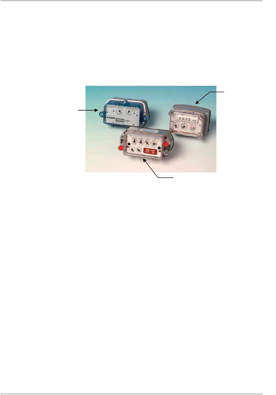
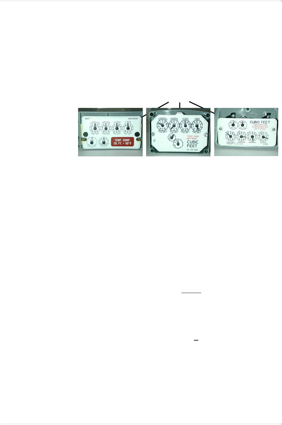
The EnergyAxis Direct Gas-meter Transponder (DGT) is designed
for use with most residential diaphragm meters. EnergyAxis Direct
Gas-meter Transponders for residential meters are available in
three distinct types:
• Type A = American Meter Company® products
• Type R & R415 = Rockwell / Equimeter / Invensys®
• Type S = Sprague / Schlumberger / Actaris / Metris®
The EnergyAxis DGT can be programmed for use with a fixed
factor, pressure-compensated index.
The EnergyAxis DGT maintains the current time and date, which are
used to manage the recording of real-time data for retrieval as
required during the normal read cycle.
In addition to maintaining index reading, the transponder:
• Stores 35 daily index readings in separate electronic indexes
recorded at the start of the utility day. (The utility day start time
is programmable).
• Maintains interval data for each 15 minute, 30 minute or 60
minute interval (default). Up to 35 days of 60 minute interval
data will be stored by our module.
Type S
Sprague/
Schlumberger/
Actaris/Metris®
Type R & R415
Rockwell/
Equimeter/
Invensys®
Type A
American Meter Company®

VRT DIRECT GAS-METER TRANSPONDER OVERVIEW CHAPTER 3
Page 6 EnergyAxis Gas Module ― User Guide
Elster Integrated Solutions • Draft A Nov. 2007
EnergyAxis Direct Gas-meter Transponder and
Components
The EnergyAxis Direct Gas-meter Transponder is available for three
types of meters. The transponder has a high impact plastic housing
with rubber gasket and it includes the following components:
• RF transmitter
• RF receiver
• Tamper switch
• Transmit and receive antennas
• Battery
• Electronic components
The meter’s existing index and index cover are attached to the
EnergyAxis gas-meter transponder during installation.
The index cover is not shipped with the standard transponder, but
may be purchased separately, if needed. (See page 16)
Identifying the Components
To determine the transponder type for each meter, refer to the photo
on the previous page.
Each shipment of transponders includes all of the hardware
necessary to successfully install a transponder onto a meter. This
hardware includes index screws to attach the index to the
transponder, three or four longer bolts to attach the
transponder/index assembly to the meter, two vandal plugs, and an
index cover gasket as shown in the photos below. Index covers are
sold separately.
This hardware can also be purchased separately.
Type A hardware
Type R & R415 hardware
Type S hardware
CHAPTER 3 VRT DIRECT GAS-METER TRANSPONDER OVERVIEW
EnergyAxis Gas Module ― User Guide Page 7
Elster Integrated Solutions
•
Draft Rev A Nov. 2007
EnergyAxis Direct Gas-meter Transponder H/W by Meter Type (and
P/N)
Meter Manufacturer American (A)
Invensys/Rockwell
(R & R415) Metris/Sprague (S)
Index screw 52800P063 1 10528P002 2 52800P063 1
Meter mounting bolt 10529P001 3 10529P003 4 10529P002 5
Index cover gasket 11401P001 6 11401P002 7 11401P003 8
Vandal plug (tamper seal) 52548P010 --- 11302P002 --- 11302P003 ---
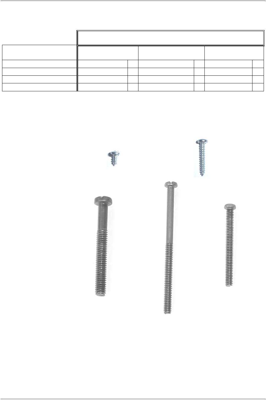
Screws
The following photos indicate the actual size and shape of the
different screws and index cover gaskets used.
4
3” partial
thread
(R & R415)
3
2¼” partial
thread
(A)
5
2” full
thread
(S)
Meter
Mounting
Bolts
Index
Screws
1
3/8” Sheet Metal
(A, S)
2
7/8” Sheet Metal
(R & R415)

VRT DIRECT GAS-METER TRANSPONDER OVERVIEW CHAPTER 3
Page 8 EnergyAxis Gas Module ― User Guide
Elster Integrated Solutions • Draft A Nov. 2007
6
Cork Index
Cover Gasket
(A)
7
Cork Index
Cover Gasket
(R & R415)
8
Cork Index
Cover Gasket
(S)
Index Cover
Gaskets

CHAPTER 3 VRT DIRECT GAS-METER TRANSPONDER OVERVIEW
EnergyAxis Gas Module ― User Guide Page 9
Elster Integrated Solutions
•
Draft Rev A Nov. 2007
How the EnergyAxis Direct Gas-meter
Transponder Works
When a EnergyAxis DGT is installed on a meter the installer
programs the mechanical index reading into the transponder.
Converting Mechanical Count into Electronic Form
During normal operation, the mechanical index accumulates its
count. The transponder keeps track of the index reading by counting
the number of rotations of the index’s drive dial.
Storing Readings
Once a day, at a pre-programmed time specified by the utility, the
transponder stores the current index reading into the electronic
index for that day.
The transponder maintains daily reading history for the past 35
days.
Between 1 an 4 interval values per hour—can accumulate
consumption in separate electronic indexes as well.
Operation Cycle
To maximize battery life, the EnergyAxis gas-meter transponder
changes from its normal, low-power quiescent state every 2
seconds into an intermediate power state for 5.5 milliseconds in
order to perform three tasks:
• Update the electronic indexes for the meter reading, daily
reading and interval reading
• Poll the tamper detection switch
• Check to see if a valid interrogation signal is being received
If and when a valid interrogation signal is received, a two-way
communication link is established.
Meter reading data is then transmitted to the interrogator.
Data collected by an interrogator is validated and stored for
uploading to Route Manager Software later.
VRT DIRECT GAS-METER TRANSPONDER OVERVIEW CHAPTER 3
Page 10 EnergyAxis Gas Module ― User Guide
Elster Integrated Solutions • Draft A Nov. 2007
Specifications
The following table shows the specifications of the EnergyAxis
Direct Gas-meter Transponder:
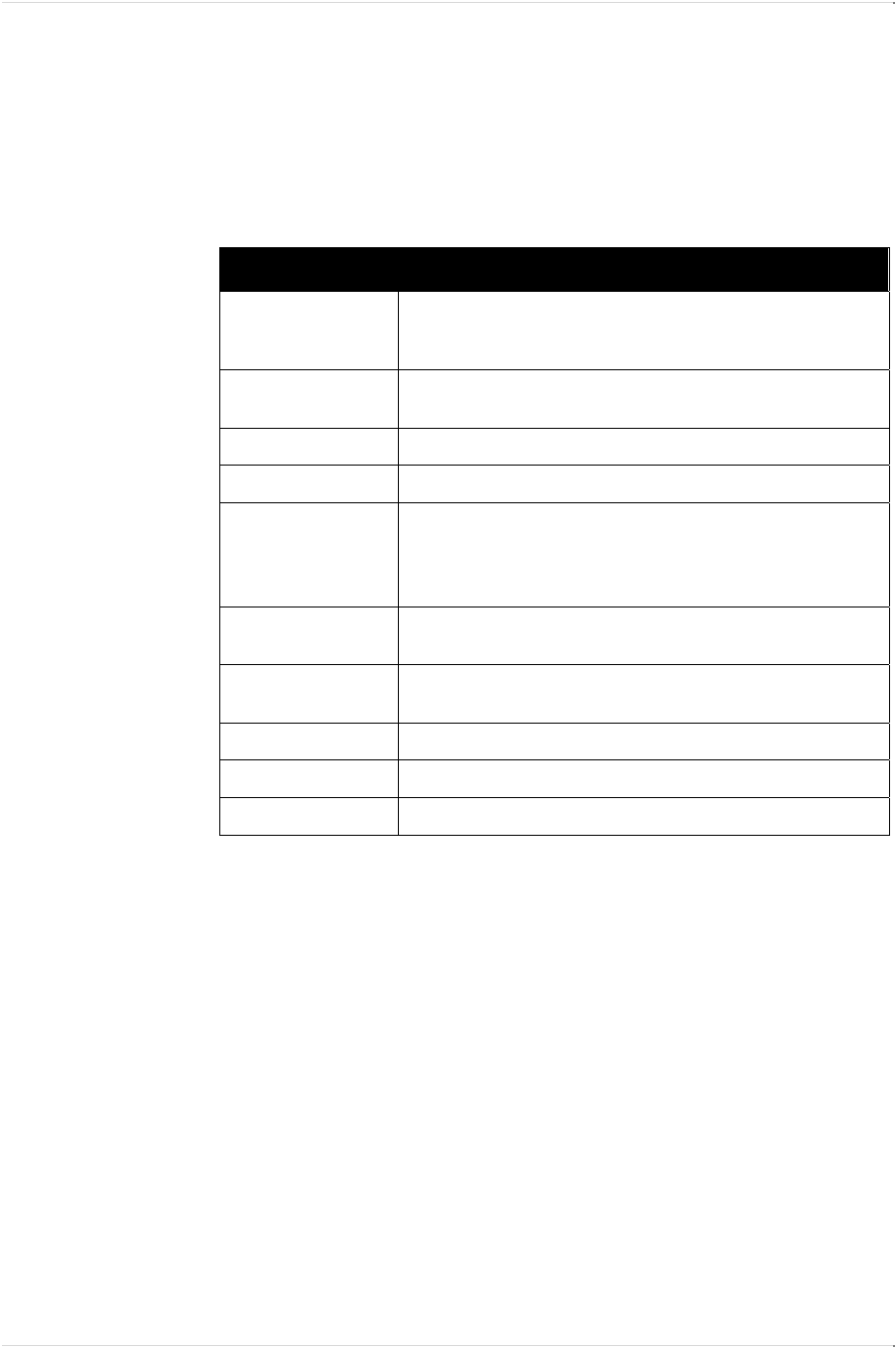
EnergyAxis DGT Specifications
Power One (1) lithium–thionyl chloride 2750 mAmp-hours; 20 years calculated
life under normal working conditions. The battery can be easily
replaced in the field.
FCC Compliance 47CFR Part 15.247: A user license is not required
(G8JEAGAS01)
RF Transmitter
RF Receiver
Materials • Housing: high-impact plastic, weatherproof, UV protected for
outdoor installation.
• Circuit-card assembly: conformal-coated
• Corrosion–protected external-housing screws
Operating
Temperature Range
Storage Temperature
Range
Humidity
Weight
Serial Numbers

CHAPTER 4 VRT DIRECT GAS-METER TRANSPONDER INSTALLATION
EnergyAxis Gas Module ― User Guide Page 11
Elster Integrated Solutions
•
Draft Rev A Nov. 2007
Chapter Four
EnergyAxis Direct Gas-meter Transponder
Installation
Installing the EnergyAxis DGT on any of the four types of meters (A,
R415, R and S) is quick and easy.
We estimate the complete process (including initial baseline
programming) will take an experienced installer about five minutes
to complete, assuming all tools, equipment and materials are on
hand.
Tools, Equipment and Materials
All or some of the following items may be needed in order to install
the transponder, depending upon the type of meter/index and the
condition of the old index cover and gaskets:
• EnergyAxis Direct Gas-meter Transponder
• EnergyAxis Handheld interrogator/programmer
• Index screws (2 each) *
• Meter mounting bolts (3 or 4 each, depending upon the meter
type) *
• Index cover (if old one is not reusable)
• Index cover gasket *
• Putty knife or scraper (to remove old gaskets)
• #2 Phillips screwdriver
• Awl (to remove existing vandal plugs)
• Vandal plugs (2 each) *
• Pressure-compensation factor value, if needed (obtain from
Elster Integrated Solutions)
* Supplied with the transponder
VRT DIRECT GAS-METER TRANSPONDER INSTALLATION CHAPTER 4
Page 12 EnergyAxis Gas Module ― User Guide
Elster Integrated Solutions • Draft A Nov. 2007
Preparation and Installation
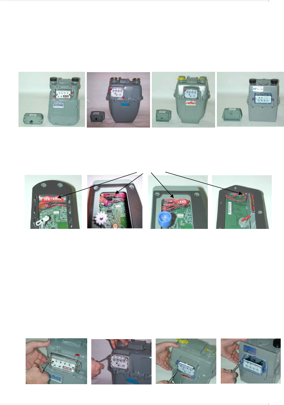
Preparation
1. Prior to removing the existing index and index cover, verify that
the transponder style is compatible with the meter style.
2. Verify the transponder battery is properly seated, and that the
battery wires are tucked neatly beside it, out of the way of the
wriggler and other transponder components.
NOTE: When transporting transponders to the field for installation
please take care not to jar the housing and dislodge the battery from
the bracket.
Installing Index onto Transponder
1. Remove the existing index cover and index (or transponder)
from the meter (An awl can be used to remove the existing
vandal plugs)
• Clean any debris from index and cover.
Battery & wires
Type R415 Type R Type S
Type A
Type A Type R415 Type S
Type R
Type A Type S
Type R
Type R415

CHAPTER 4 VRT DIRECT GAS-METER TRANSPONDER INSTALLATION
EnergyAxis Gas Module ― User Guide Page 13
Elster Integrated Solutions
•
Draft Rev A Nov. 2007
2. Remove the gasket and any adhesive material from the meter.
• Use a scraper or putty knife.
3. Align index wriggler with transponder wriggler, as shown below.
4. Attach the index to transponder.
• Use two (2) appropriate index screws.
CAUTION: Do not over tighten index screws.
Checking Mechanical Operation
This procedure will verify the attached index rotates freely and
without resistance.
1. Rotate the index drive dial 3 times clockwise.
2. If it turns easily, rotate the drive dial 3 times counterclockwise.
• This will remove counts or subcounts from the mechanical
index.)
• If it does not turn easily, first rotate the drive dial 3 times
counterclockwise to remove subcounts from the mechanical
index. Second, unscrew the index/transponder assembly
and repeat from Step 3 of the previous section.
NOTE: Subcounts added to the electronic index during this
procedure will be cleared when the index reading is programmed
into the transponder.
Type A Type R Type S Type R415
VRT DIRECT GAS-METER TRANSPONDER INSTALLATION CHAPTER 4
Page 14 EnergyAxis Gas Module ― User Guide
Elster Integrated Solutions • Draft A Nov. 2007
Checking Mechanical Index to Electronic Index
Operation
This procedure will verify the electronic index is properly recording
counts and subcounts corresponding with those of the mechanical
index.
1. Rotate the transponder wriggler till the drive dial is in the 12
o’clock position.
2. Electronically read the transponder subcounts.
• Use an Handheld or other suitable interrogator/programmer.
• Remember the subcount value.
3. Facing the index, rotate the drive dial 3 times counterclockwise.
Stop at the 12 o’clock position.
4. Electronically read the new transponder subcounts.
• Use an Handheld or other suitable interrogator/programmer.
• Observe the new subcount value and calculate the
difference between it and the starting subcount value.
5. If the new subcount value is exactly 3 subcounts higher than the
original reading, proceed to step 8.
6. If the new subcount value is less than 3 subcounts higher,
consider whether the subcounts may have rolled over during the
test.
• If it appears the discrepancy is due to rollover, proceed to
step 8.
7. If the new subcount value is less than 3 subcounts higher,
repeat this procedure from Step 1.
• If the procedure fails a second time, replace transponder
with a new one.
Type A Type R415 & R Type S
Drive dial hand in 12 o’clock position
CHAPTER 4 VRT DIRECT GAS-METER TRANSPONDER INSTALLATION
EnergyAxis Gas Module ― User Guide Page 15
Elster Integrated Solutions
•
Draft Rev A Nov. 2007
8. By using an Handheld or other suitable
interrogator/programmer, verify that the pre-divider is correct.
(The pre-divider for a 1-ft drive is 100 and the pre-divider for a
2-ft drive is 50; refer to the Appendix for the definition of pre-
divider).
9. Remove any subcounts or counts from the mechanical index by
rotating the drive dial clockwise by the same number of counter-
clockwise rotations that were placed on the mechanical index in
the previous steps.
Mounting the Transponder/Index Assembly
NOTE: Be sure to have your transponder/index assembly,
screwdriver, index cover and index cover gasket within easy reach
before starting this procedure.
1. For Rockwell 415 Transponders Only: Install the meter
adapter to the meter using the two 6/32 supplied in the
assembly. Note: Make sure the gears on the adapter and meter
are properly meshed.
2. Visually align transponder wriggler with meter wriggler or meter
adapter (drive dog).
• If wriggler cannot be put in a fixed position, position it
correctly by rotating the drive dial with your finger.
3. Mate the transponder wriggler with the meter wriggler or meter
adapter (drive dog) and hold the mated assembly against the
meter.
4. While holding the assembly against the meter, gently try to turn
the drive wheel clockwise, then counterclockwise.
• If the drive wheel meets resistance in both directions, it is
properly mated. Proceed to Step 4.
• If it meets no resistance in either direction, and can rotate
freely through an angle of 360 degrees and beyond, then
make sure the meter is completely free of old gasket
material and forcefully press the transponder into the meter.
Repeat this step (Step 3). If the unit still does not correctly
engage with the meter, return it to Elster Integrated
Solutions.
meter Adapter
6/32 mounting
scre
w
VRT DIRECT GAS-METER TRANSPONDER INSTALLATION CHAPTER 4
Page 16 EnergyAxis Gas Module ― User Guide
Elster Integrated Solutions • Draft A Nov. 2007
• For American Meter Transponders Only: If the American
Meter transponder meets resistance in one direction then
turns 360 degrees the other way before again meeting
resistance, it is not properly mated. Repeat from Step 1.
CAUTION: It is very important that the wriggler on the
transponder is correctly engaged onto the meter. If it is not, it
could produce an erroneous indication during utility leak test
procedures that monitor drive dial (proving dial) movement.
Incorrectly engaged wrigglers could also cause meter damage.
CORRECT EXECUTION OF STEPS 1, 2 and 3 IS CRITICAL.
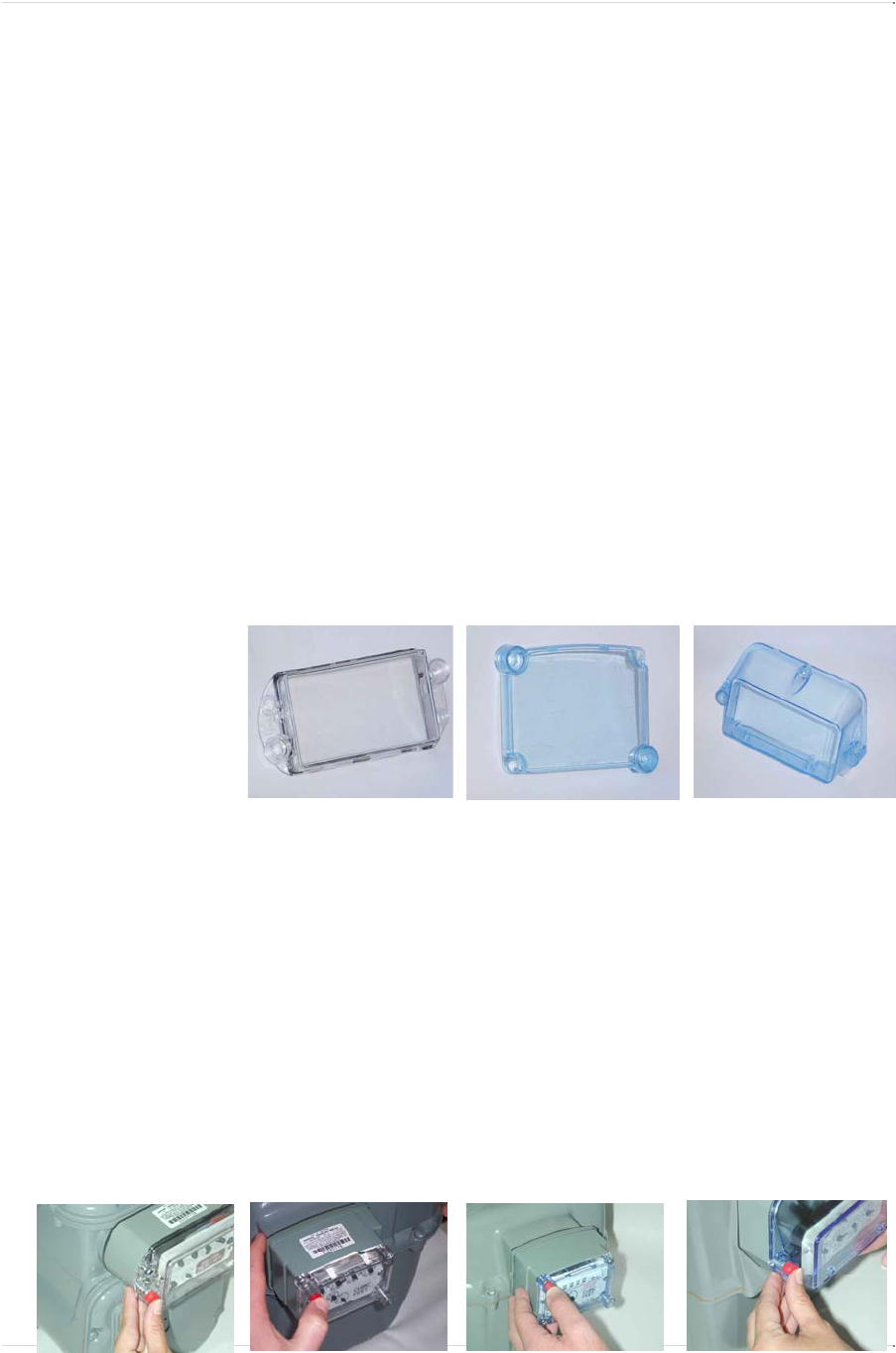
5. Verify that the gasket material on the index cover is free of rips
or tears.
• If it is not, remove the damaged gasket from the index cover
and replace with a new one.
6. Place the index cover and index cover gasket onto the
transponder/ index assembly.
• Verify the index cover is properly oriented with its vent holes
at the bottom.
• See photos below for orientation cues.
7. Screw the transponder/index/cover assembly to the meter and
tighten bolts to secure assembly to meter.
• Use the appropriate mounting bolts provided.
• Recommended torque range is 16-24 in-lbs.
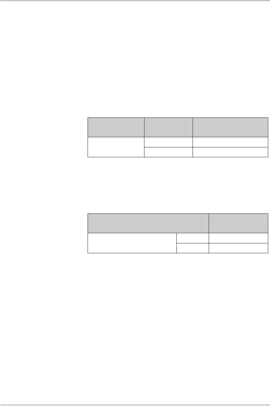
8. Install the tamper seals into the index cover receptacles.
Type
A
Top edge of lens has
continuous ridges;
bottom has intermittent
ridges. Left flange
contains an “L”
P/N 10001P001
Type R415 & R
Rectangular lens with a
curved top and flat
bottom.
P/N 10001P003
Type S
Angled lens with a single
screw groove at the top
and two screw holes on
the sides.
P/N 10001P002
Top
Bottom
Top
Top
Bottom Bottom
Type A Type R415 Type S
Type R

CHAPTER 4 VRT DIRECT GAS-METER TRANSPONDER INSTALLATION
EnergyAxis Gas Module ― User Guide Page 17
Elster Integrated Solutions
•
Draft Rev A Nov. 2007
9. Remove the semi-detached label from the transponder and
attach it to your paperwork.
Programming the EnergyAxis Direct Gas-meter
Transponder
Although transponders may contain default or utility-specified values
that are programmed during manufacturing, it is important to
program certain data only after the transponder has been installed
in the field:
• Transponders can accumulate subcounts during shipping,
handling and installation due to the movement of its wriggler.
• The transponder’s tamper sensing switch must be told which
orientation should be considered its normal (not tampered)
condition.
Therefore, all transponders (even those mated with indexes set
at 0000) should be programmed after installation on the meter.
When the transponder is programmed, it also automatically sets the
tamper flag to “false” or “not tampered,” establishing its normal
condition in the transponder’s memory.
NOTE: Even transponders factory-installed on meters must be
programmed at the time the meter is installed in the field.
Programming Procedure
NOTE: For specific instructions for programming transponders,
please refer to the appropriate interrogator/programmer user guide.
NOTE: Always verify the display of the utility-lan id on the Handheld
with that same value on the module itself to insure that
programming is being completed for the correct module..
NOTE: If required, be sure to have on hand the pressure
compensation factor. (Obtain from Elster Integrated Solutions.)
1. Read the transponder.
• Place interrogator/programmer close to the transponder,
especially if other transponders are nearby.
• If no other transponders are within 6 feet, use Wildcard
function to find transponder serial number.
• If other transponders are within 6 feet, enter the serial
number of the desired transponder.
2. Visually read the meter’s mechanical index.

VRT DIRECT GAS-METER TRANSPONDER INSTALLATION CHAPTER 4
Page 18 EnergyAxis Gas Module ― User Guide
Elster Integrated Solutions • Draft A Nov. 2007
3. Program the electronic index to match the meter ‘s mechanical
index.
• This will also reset the transponder subcounts to zero.
4. If required, program the pressure compensation factor now.
• Compensation factors are unique for specific indexes and
can be obtained by contacting Elster Integrated Solutions
Customer Service Department at (919) 250-5700.
5. Read the transponder.
• If the electronic index matches the meter ‘s mechanical
index, installation is complete.
• If the electronic index does not match the meter ‘s
mechanical index, repeat procedure from Step 1.
• If the transponder still does not program, replace it with a
new one.
CHAPTER 7 TROUBLESHOOTING
EnergyAxis Gas Module ― User Guide Page 19
Elster Integrated Solutions
•
Draft Rev A Nov. 2007
Chapter Five
EnergyAxis Remote Gas-meter
Transponder Overview
The EnergyAxis Remote Gas-meter Transponder (RGT) is
compatible with American Meter C&I meters. The pulser board is
used for both 5-ft and 10-ft indexes.
EnergyAxis RGT
Style
Meter Type Part Number*
5 ft. 52807K551-100
Meter Mount 10 ft. 52807K551-100
* Part numbers are subject to change. Be sure to include item description when ordering.
NOTE: The EnergyAxis RGT can be purchased without the 5/1010-
ft pulser board so that third-party pulser kits may be attached.
Additional EnergyAxis pulser boards with mounting kits are also
available:
EnergyAxis Pulser Board w/ Mounting
Kit
Part Number*
5 ft. 52807K001
Pulser board, 2 mounting screws,
6 spacers 10 ft. 52807K002
* Part numbers are subject to change. Be sure to include item description when ordering.

APPENDIX
Page 20 EnergyAxis Gas Module ― User Guide
Elster Integrated Solutions • Draft A Nov. 2007
How it Works
The EnergyAxis RGT is designed for use with commercial gas
meters where the meter/index design prohibits direct transponder
attachment.
A “pulser” circuit board is interfaced with the index gears to provide
an electronic “pulse” that translates each turn of the mechanical
gear into electronic pulses. These pulses are sent via a cable to the
transponder where they are recorded as consumption values.
Most applications accommodate connection of the transponder
within one foot of the meter. However, certain applications (where
the meter is obscured by metallic materials that can block radio
signals, for example) a remote transponder with a longer cable may
be special ordered so that the transponder can be mounted farther
away from the meter in a position more favorable for interrogation.
Features and Capabilities
The EnergyAxis RGT can be programmed for use with a fixed
factor, pressure-compensated index.
The transponder maintains current time and date, which are used to
manage the recording of real-time data for retrieval as required
during the normal read cycle.
In addition to maintaining index reading, the transponder:
• Stores 35 daily index readings in separate electronic indexes
recorded at the start of the utility day. (The utility day start time
is programmable.)
• Maintains up to four time-of-use (TOU) electronic indexes that
each have programmable start and stop times.
EnergyAxis Remote Gas-meter Transponder
Construction
The EnergyAxis RGT is available for American Meter 5-foot and 10-
foot meters. The transponder has a high impact plastic housing with
rubber gasket and it includes the following internal components:
• RF transmitter
• RF receiver
• Tamper switch
• Transmit and receive antennas
• Battery
• Electronic components

CHAPTER 7 TROUBLESHOOTING
EnergyAxis Gas Module ― User Guide Page 21
Elster Integrated Solutions
•
Draft Rev A Nov. 2007
The meter’s existing index and index cover are attached to the
EnergyAxis RGT pulser board during installation.
APPENDIX
Page 22 EnergyAxis Gas Module ― User Guide
Elster Integrated Solutions • Draft A Nov. 2007
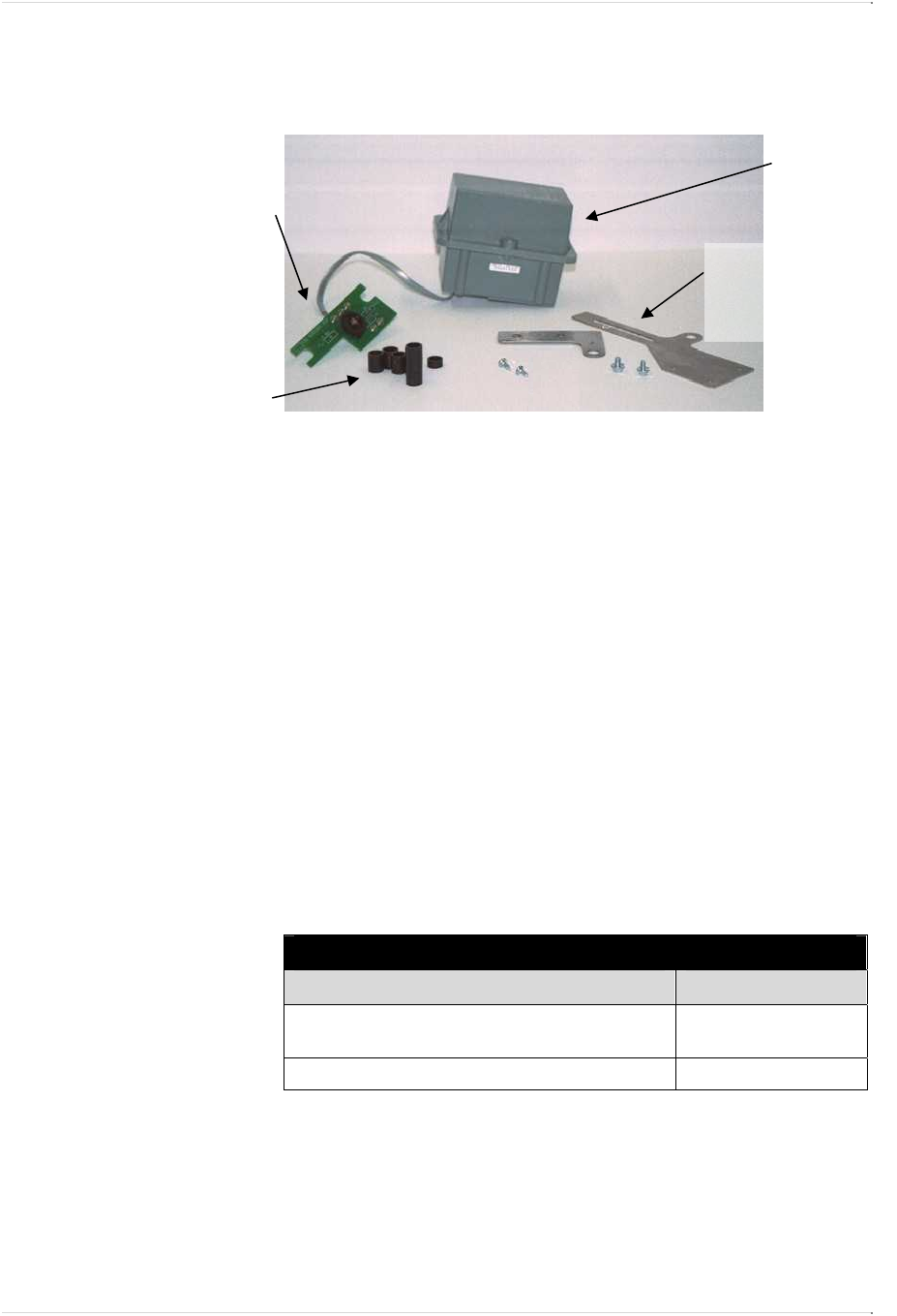
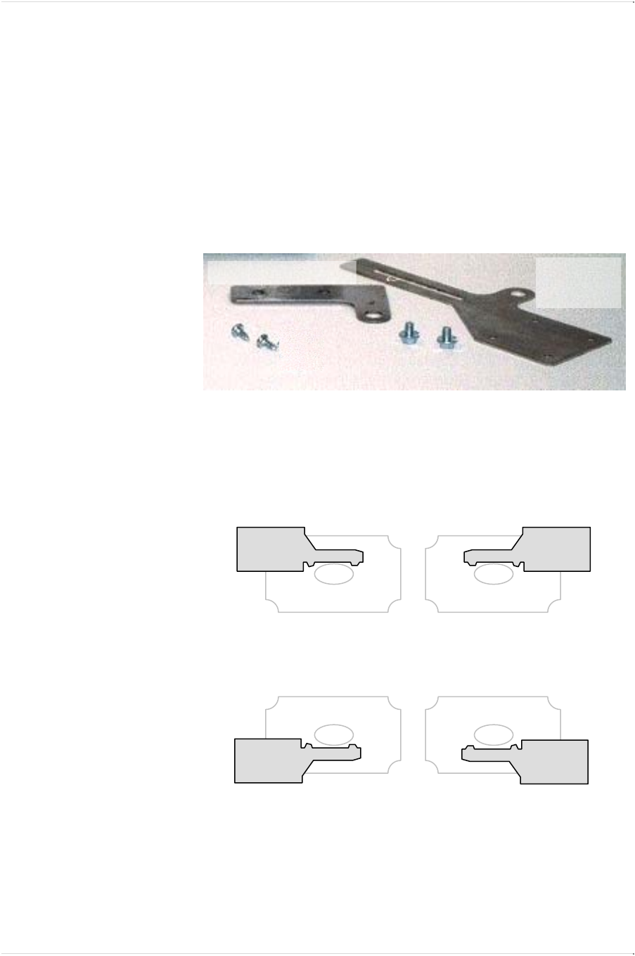
Identifying the Components (Meter Mount)
Each shipment of EnergyAxis RGTs includes all the hardware
necessary to successfully install a transponder onto a meter.
You will receive:
• The meter-mount transponder
• A 5-ft /10-ft meter pulser board connected to the transponder by
a standard one-foot cable.
CAUTION: Use extreme care transporting and installing the
pulser board. The glass reed switches are extremely fragile.
Keep the protective bubble wrap on the pulser board until
installation.
• Six (6) plastic spacers (2 short, 2 tall/fat post, 2 tall/thin post) to
position the pulser board on the index
• Meter mounting kit (2 brackets with 2 hex-head slide screws
and 2 Phillips-head screws)
Meter-mounting hardware can also be purchased separately. See
table below for part numbers.
To Order Additional Meter-mount Hardware
Item Part Number
Meter Mounting Kit (2 brackets, 2 mounting
screws, 2 hex slide screws) 52805K004
Pulser Mounting Kit (6 spacers) 52807K003
* Part numbers are subject to change. Be sure to include item description when ordering.
American
Meter 5/10 ft.
Pulser board
Mounting kit with:
• brackets (2)
• slide screws (2)
• mounting screws (2)
Spacers (6)
Meter-mount
remote VRT
gas
trans
p
onde
r
CHAPTER 7 TROUBLESHOOTING
EnergyAxis Gas Module ― User Guide Page 23
Elster Integrated Solutions
•
Draft Rev A Nov. 2007
Chapter Six
EnergyAxis Remote Gas-meter Transponder
Installation
Installing the EnergyAxis RGT on American Meter 5-ft and 10-ft
meters is quick and easy.
We estimate the complete process (including initial baseline
programming) will take an experienced installer about five minutes
to complete, assuming all tools, equipment and materials are on
hand.
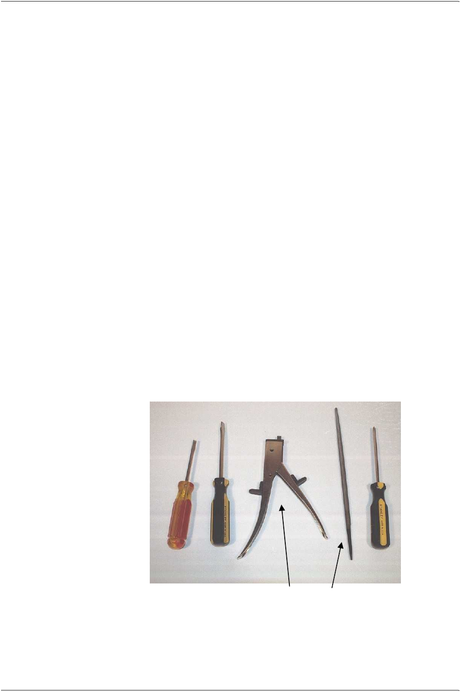
Tools, Equipment and Materials
All or some of the following items may be needed in order to install
the transponder.
Tools Required:
• 3/8" flat blade screwdriver
• 3/16" flat blade screwdriver
• Nibbling tool or small file
• #1 Phillips screwdriver
Not shown:
• Awl
• 5/16 English socket or adjustable wrench (optional, for meter-
mount only)
Flat blade
screwdrivers
Nibbling tool or small file
Phillips
screwdriver
APPENDIX
Page 24 EnergyAxis Gas Module ― User Guide
Elster Integrated Solutions • Draft A Nov. 2007
Equipment & Materials
• Replacement seals
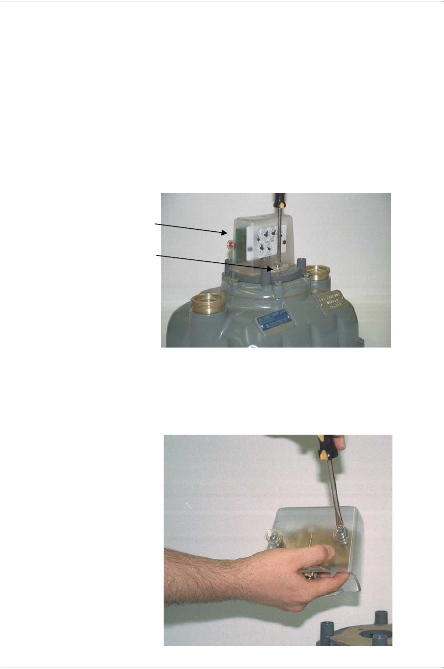
Pulser Installation (Meter-mount)
NOTE: Although this section illustrates installation of the 5 ft pulser
board, the procedure is essentially the same for the 10 ft pulser
board.
1. Remove the index box from the meter.
• If the meter index box has a back cover, remove the 2
screws that secure it first.
• Remove the screws securing the index box to the meter.
• Save all screws.
2. Remove the 2 screws that secure the index to the index box.
• Save the screws.
Remove back cover of
index box first
(if applicable).
Then remove index
box from meter.
CHAPTER 7 TROUBLESHOOTING
EnergyAxis Gas Module ― User Guide Page 25
Elster Integrated Solutions
•
Draft Rev A Nov. 2007
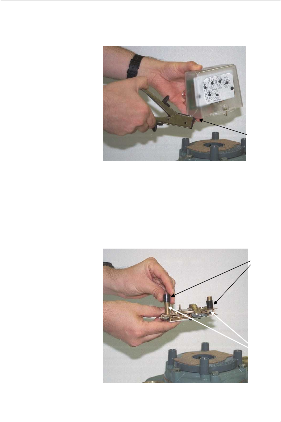
3. Cut a small notch in the base of the index box (on the left side
near the back).
• Use either the nibbling tool or file.
• The notch should be only large enough to allow the
connecting cable to pass through.
CAUTION: The notched index cover should fit snugly over
the cable but not so tightly that the wires inside may be
broken or crimped when the box is tightened down.
4. Place a tall spacer over each of the 2 posts protruding from the
back of the index.
• Use either tall spacer A (1/2”) or B (7/8”) depending upon
the width of the index post. (See illustration below.)
Cut a small
notch on left
side of the
base (near
the back) to
pass cable
though.
Index
posts
Tall
spacers
APPENDIX
Page 26 EnergyAxis Gas Module ― User Guide
Elster Integrated Solutions • Draft A Nov. 2007
To Order Additional Spacers
Item Part Number*
A 1/2” Tall spacer for fat post 52807P002
B 7/8” Tall (2 tiered) spacer for thin post 52807P003
C 1/4” Short spacer (all) 52807P004
* Part numbers are subject to change. Be sure to include item description when ordering.
5. Fit the pulser board over the index posts onto spacers:
• Hold index in one hand, face-down.
• Position pulser board so that its circular notches align with
the index posts and the pulser gear faces the index gears.
• Slide the pulser board onto the posts.
• Ensure pulsar gears mate with index gears.
• Ensure the gears mesh smoothly by turning the input
wriggler.
•
See assembly illustration below.
Index faceplate
Index posts with
spacers beneath
p
ulse
r
Pulser board
A
TALL
1/2”
(fat post)
C
SHORT
1/4”
(both posts)
B
TALL
7/8”
(thin post)
Pulser board spacer types (2 of each type in kit)
FAT POST
spacer
combo
THIN POST
spacer
combo
A + C B + C
CHAPTER 7 TROUBLESHOOTING
EnergyAxis Gas Module ― User Guide Page 27
Elster Integrated Solutions
•
Draft Rev A Nov. 2007
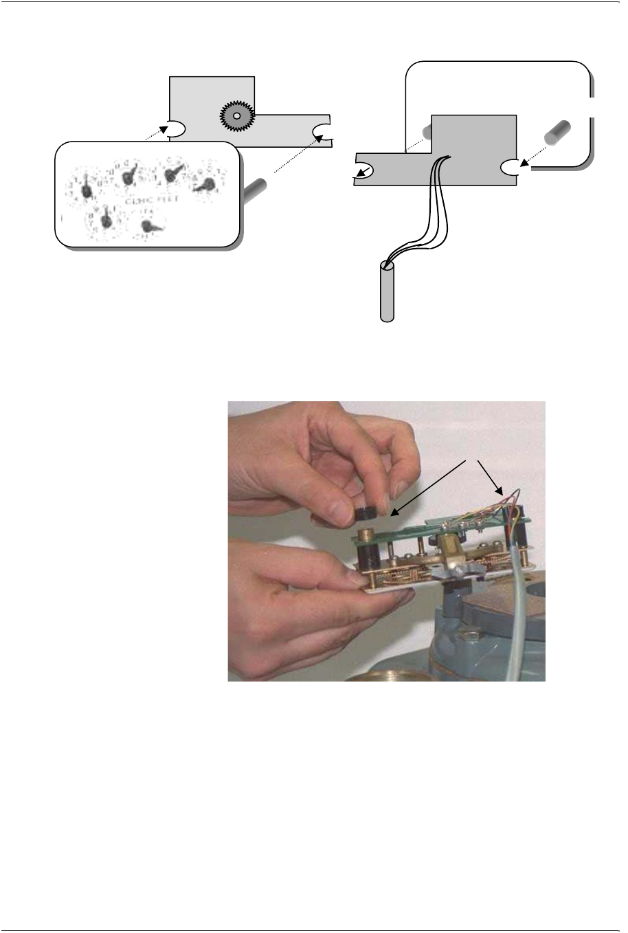
6. Slip one of the short spacers over the portion of each post
protruding above the pulser board.
7. Route the pulser wires toward the notch cut earlier in the index
box.
• Be sure the wires are not pinched under either the posts or
the spacers.
Put short spacers
on protruding
portion of posts
Pulser board
(front)
Faces toward
index, gears
en
g
a
g
ed
INDEX (back)
INDEX (front)
Pulser board
(back)
Index post
Index p
ost
APPENDIX
Page 28 EnergyAxis Gas Module ― User Guide
Elster Integrated Solutions • Draft A Nov. 2007
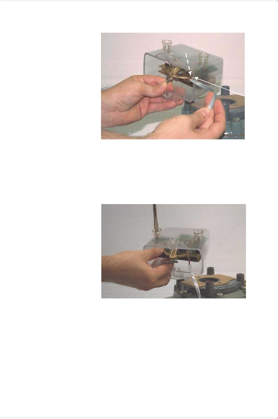
8. Slide the index/pulser assembly into the index box.
9. Reattach the index/pulser assembly to the index box.
• Use the 2 screws removed in Step 2.
• Ensure that the wires are not pinched anywhere before
tightening screws.
• Verify that the index turns without binding.
Route wires
toward the
notch in the
index box.
Make sure
they’re not
pinched
under posts
or spacers
Notch
CHAPTER 7 TROUBLESHOOTING
EnergyAxis Gas Module ― User Guide Page 29
Elster Integrated Solutions
•
Draft Rev A Nov. 2007
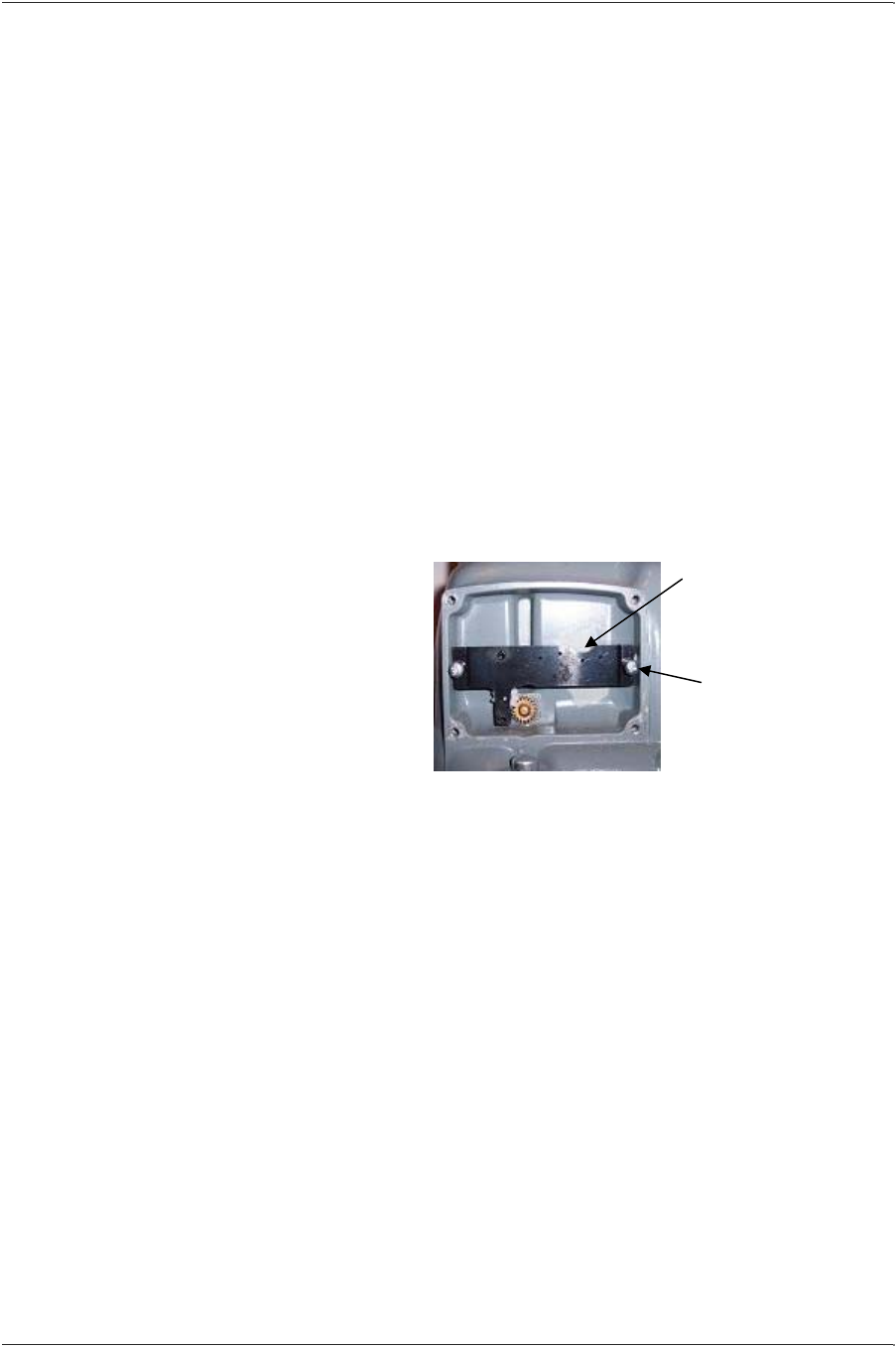
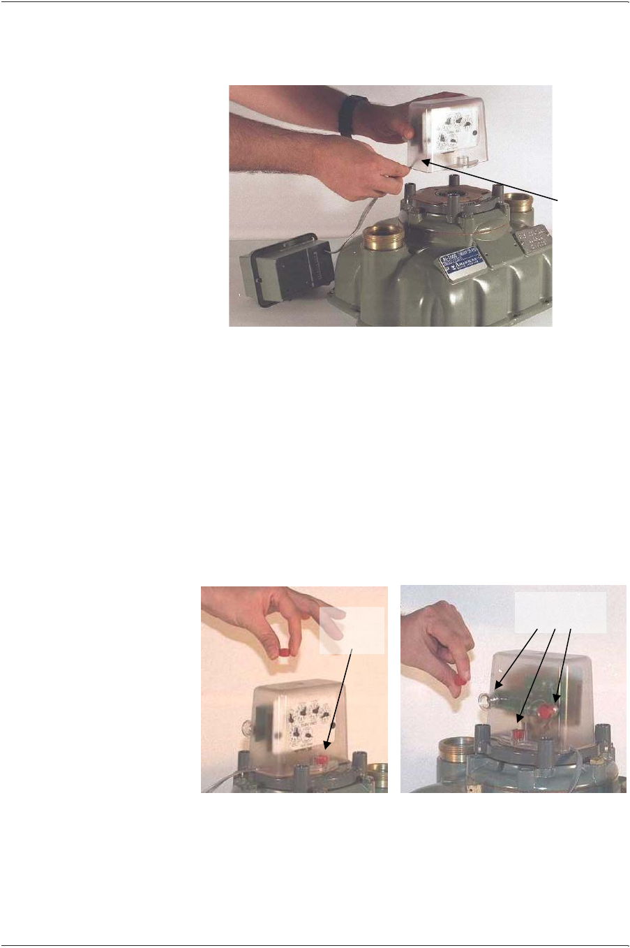
10. Position the index box (with index/pulser assembly) over the
screw holes in the meter flange.
• Ensure that the individual pulser wires are well inside the box
and the insulated section of cable exits via the notch made in
Step 3. Take precaution to ensure that the index and pulser
board are protected from rain or snow.
11. If the index box has a back cover, reinstall it now.
• Use the screws removed in Step 1.
12. Mount the index box (and attached index/pulser assembly) to
the meter flange.
• Use the screws removed in Step 1.
13. Reseal all screws with new seals.
14. Mount the transponder to the meter.
• Refer to the applicable transponder mounting procedure
below for specific instructions.
Route the
cable
through the
notch.
Make sure
the end of
the
insulated
covering is
well inside
the box.
Replace seals
on screws
Replace
seals on
screws
FRONT REAR
APPENDIX
Page 30 EnergyAxis Gas Module ― User Guide
Elster Integrated Solutions • Draft A Nov. 2007
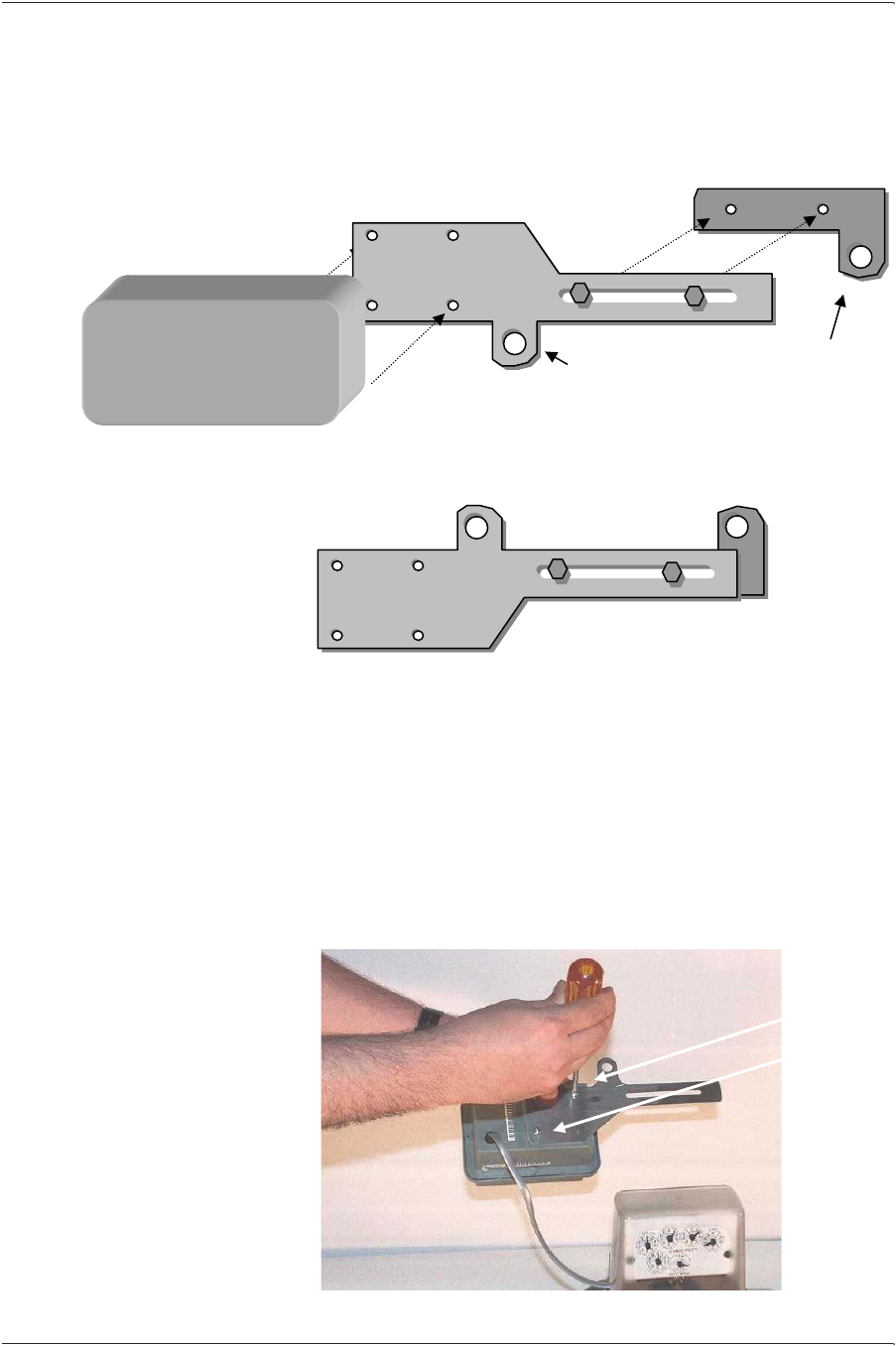
EnergyAxis RGT Mounting (Meter-mount)
Tools, Equipment and Materials
For this part of the installation you will need the following:
• Metal bracket sections (A & B)
• Hex-head slide screws (2)
• Phillips-head mounting screws (2)
• (Optional) 5/16ths English socket or adjustable wrench
Meter Mounting Positions
The transponder may be installed in either of two positions (left-
hand or right-hand) on either the front or back of the meter.
Meter FRONT
LEFT-HAND
Meter FRONT
RIGHT-HAND
Mounting positions: meter front
Meter FRONT
LEFT-HAND
Meter FRONT
RIGHT-HAND
Mounting positions: meter rear
Hex-head
slide screws
Bracket A
(transponder
section)
Bracket B
(
meter section
)
Phillips-head
mounting screws
CHAPTER 7 TROUBLESHOOTING
EnergyAxis Gas Module ― User Guide Page 31
Elster Integrated Solutions
•
Draft Rev A Nov. 2007
Meter-mounting Procedure
The illustrations below show how the meter-mount brackets should
be assembled (for right-hand or left-hand mounting) prior to
attaching them to the meter.
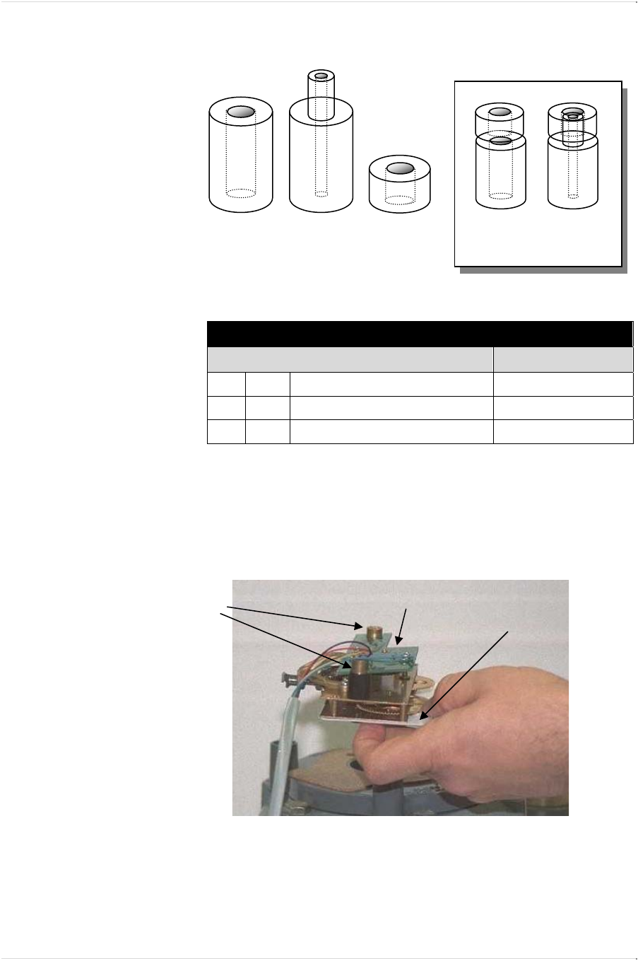
1. Attach bracket A to bottom of the transponder.
• Use the 2 Phillips-head screws, placed in diagonal
positions.
• Although transponder has only 2 holes on its base, the
bracket has 4 holes to accommodate left- or right-hand
mounting.
• Do not over-tighten the screws.
Attach
transponder
base here
Brackets assembled for LEFT-HAND mounting
Adjust distance between meter mounting
holes using slide screws and slot.
B
Attach
transponder
base here
Transponder
TOP
Brackets assembled for RIGHT-HAND mounting
A
A
Mount
transponder
to bracket
using the 2
Phillips-head
screws in
diagonal
positions.
APPENDIX
Page 32 EnergyAxis Gas Module ― User Guide
Elster Integrated Solutions • Draft A Nov. 2007
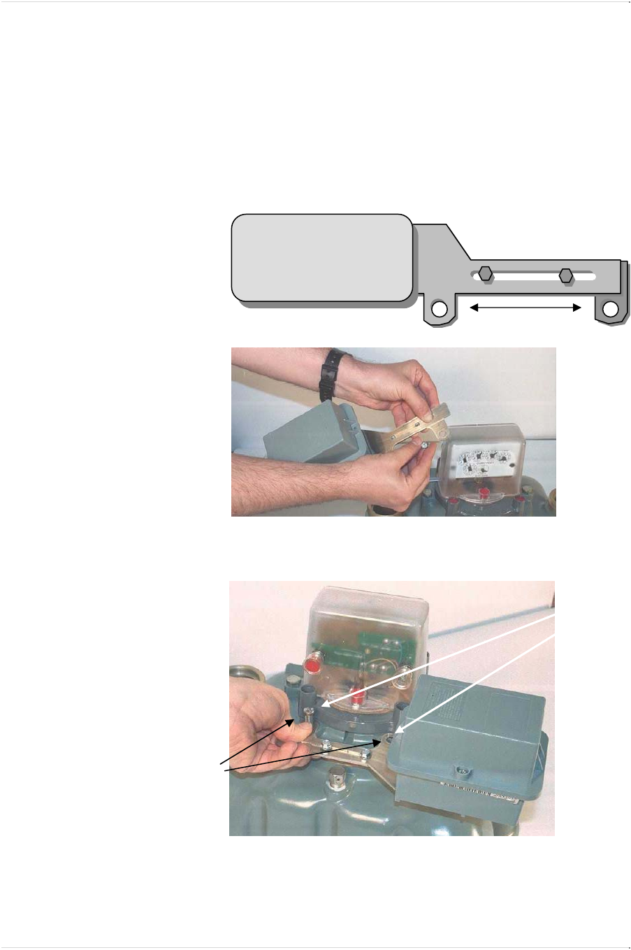
2. Connect brackets A and B using the 2 hex-head slide screws.
• The screw heads should be on the outside of the slot on
bracket A, with their threads started in bracket B holes.
• Slightly finger-tighten the screws so that the bracket width
can still be adjusted.
• The hex screws should be on top—regardless which
mounting position you use—when the bracket assembly is
connected to the meter.
3. Remove the two slotted screws already attached to the meter in
the selected mounting location (front or back).
4. Position the transponder brackets in the mounting location and
adjust the bracket mounting holes to the width of the meter
holes.
Align bracket
mounting
holes with the
mounting
screws
already
installed in
the meter.
Remove
slotted
mounting
screws from
meter
Shown: RIGHT-HAND mounting, meter REAR
B
A
A
Transponder
TOP
CHAPTER 7 TROUBLESHOOTING
EnergyAxis Gas Module ― User Guide Page 33
Elster Integrated Solutions
•
Draft Rev A Nov. 2007
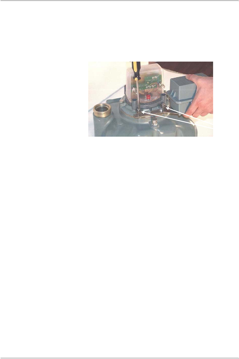
5. Secure slide screws into position.
• You may be able to finger-tighten these sufficiently, but it is
recommended you use either an adjustable wrench or a
3/16ths English socket to secure the slide.
6. Mount the transponder to meter in desired location.
• Use the 2 slotted screws previously removed from the
meter.
• Do not over-tighten screws.
7. Dress pulser cable neatly.
• Tie up or bind any excess cable and position it out of harm’s
way.
8. Program the transponder to the reading on the index.
• Refer to the programming procedure at the end of this
chapter for specific instructions.
Meter
slotted
screws

APPENDIX
Page 34 EnergyAxis Gas Module ― User Guide
Elster Integrated Solutions • Draft A Nov. 2007
EnergyAxis RGT Programming (All)
NOTE: The procedure for programming the EnergyAxis Remote
Gas-meter Transponder is identical to that used for programming
the EnergyAxis Direct Gas-meter Transponder as described earlier
in this manual.
Although transponders may contain default or utility-specified values
that are programmed during manufacturing, it is important to
program certain data only after the transponder has been installed
in the field:
• Transponders can accumulate subcounts during shipping,
handling and installation due to the movement of its wriggler.
• The transponder’s tamper sensing switch must be told which
orientation should be considered its normal (not tampered)
condition.
Therefore, all transponders (even those mated with indexes set
at 0000) should be programmed after installation (on meter).
When the transponder is programmed, it also automatically sets the
tamper flag to “false” or “not tampered,” establishing its normal
condition in the transponder’s memory.
NOTE: Even transponders factory-installed on meters must be
programmed at the time the meter is installed in the field.
Programming Procedure
NOTE: For specific instructions for programming transponders,
please refer to the appropriate interrogator/programmer user guide.
NOTE: If required, be sure to have on hand the pressure
compensation factor. (Obtain from Elster Integrated Solutions.)
1. Read the transponder.
• Place interrogator/programmer close to the transponder,
especially if other transponders are nearby.
• If no other transponders are within 6 feet, use Wildcard
function to find transponder serial number.
• If other transponders are within 6 feet, enter the serial
number of the desired transponder.
2. Visually read the meter’s mechanical index.
3. Verify that the transponder is programmed for the proper index
drive. If it is not re-program it.
4. Program the electronic index to match the meter ‘s mechanical
index.

CHAPTER 7 TROUBLESHOOTING
EnergyAxis Gas Module ― User Guide Page 35
Elster Integrated Solutions
•
Draft Rev A Nov. 2007
• This will also reset the transponder subcounts to zero.
5.. If required, program the pressure compensation factor now.
• Compensation factors are unique for specific indexes and
can be obtained by contacting Elster Integrated Solutions
Customer Service Department at (919) 250-5700.
6.. Read the transponder.
• If the electronic index matches the meter ‘s mechanical
index, installation is complete.
• If the electronic index does not match the meter ‘s
mechanical index, repeat procedure from Step 1.
• If the transponder still does not program, replace it with a
new one.

Page 36 EnergyAxis Gas Module ― User Guide
Elster Integrated Solutions • Draft A Nov. 2007
Appendix
EnergyAxis Direct Gas-meter Transponders can be programmed (at
the factory or in the field) with values specified by the utility.
This Appendix highlights some of the types of data that can be
programmed at the factory and the range of selections within each
type.
For comprehensive discussion of all programmable transponder
data, please refer to the applicable interrogator/programmer user
guide.
Pre-Divider
The number of subcounts recorded with each revolution of the drive
dial on 1-ft3 and 2-ft3 indexes is one. A 1-ft3 index requires 100
revolutions to yield 100 ft3 (1 count) and a 2-ft3 index requires 50
revolutions to yield 100 ft3 (1 count). Therefore, the pre-divider for a
1-ft3 index is 100 and for a 2-ft3 index it is 50.
Pressure-Compensation Factor
When a transponder is used in conjunction with a pressure-
compensated index, a pressure-compensation factor can be
programmed into the transponder memory by the utility at the time
of installation to ensure that the electronic index reading agrees with
the mechanical index.
Pressure-compensation factors are unique for specific indexes and
can be obtained by contacting Elster Integrated Solutions’ Customer
Service Department at (919) 250-5700.