Elster Solutions EAMOBILE1 Vehicle-Based Mobile Wireless Meter Reading Equipment User Manual Real Time Mobile Interrogator User Guide
Elster Solutions, LLC Vehicle-Based Mobile Wireless Meter Reading Equipment Real Time Mobile Interrogator User Guide
User Manual
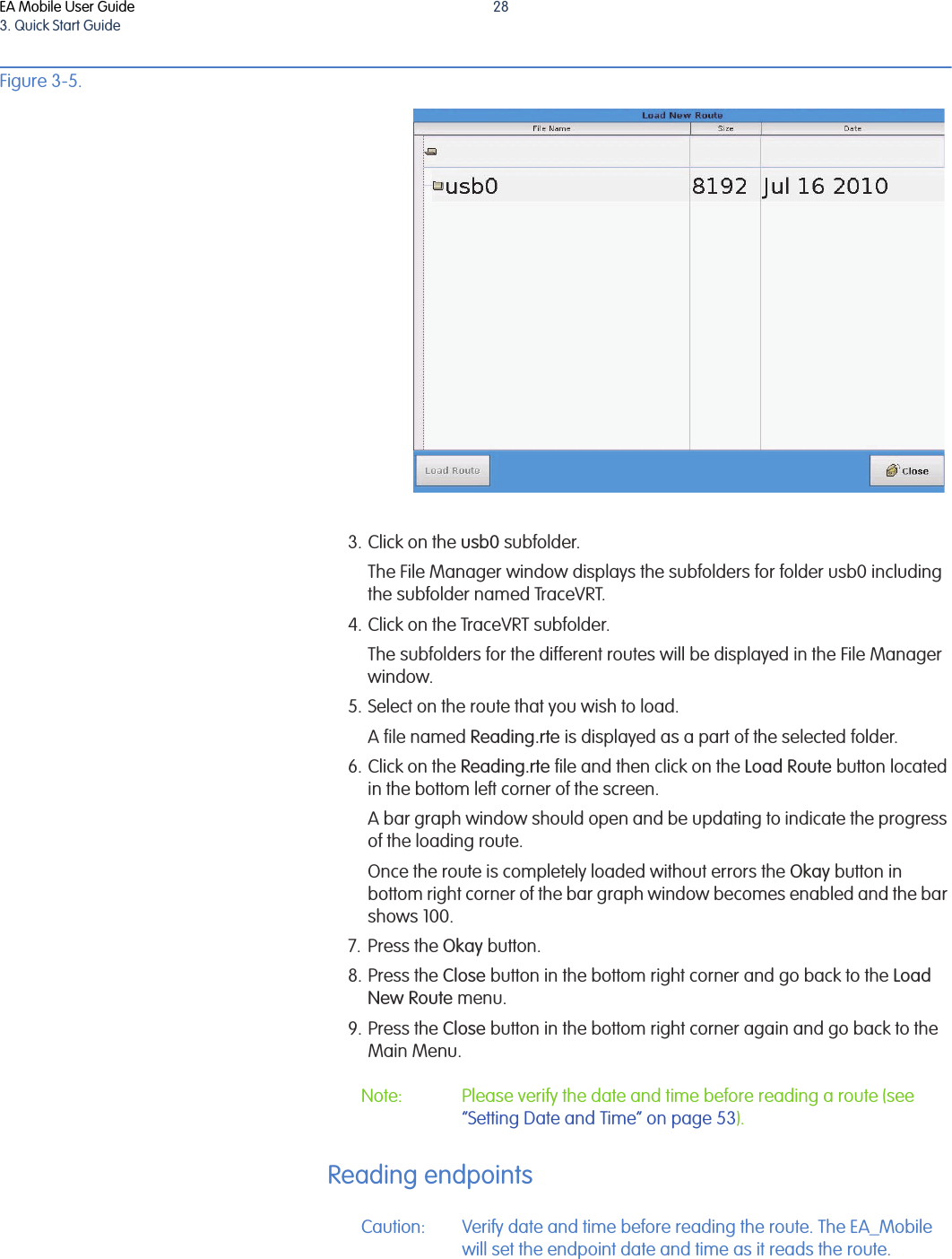
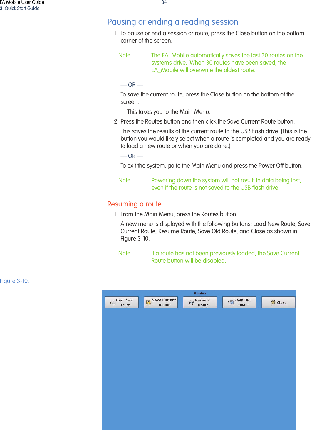
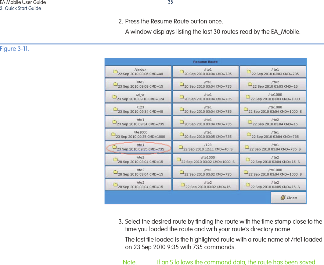
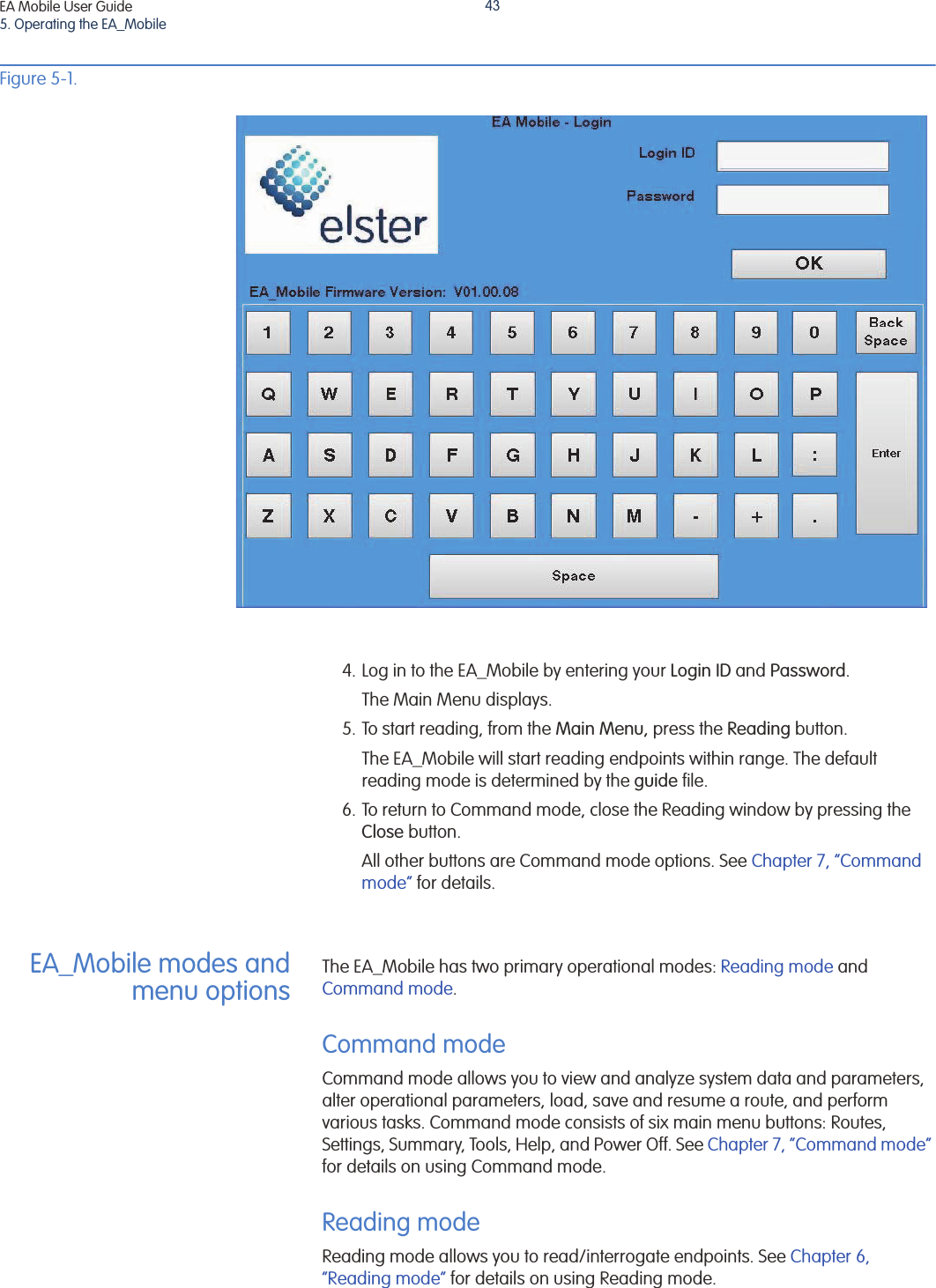
![EA Mobile User GuideContents4Option 1 -to a dashboard . . . . . . . . . . . . . . . . . . . . . . . . . 18Option 2 - to a windshield . . . . . . . . . . . . . . . . . . . . . . . . 19Connecting the monitor to the EA_Mobile. . . . . . . . . . . . . . . . . . 193 Quick Start Guide . . . . . . . . . . . . . . . . . . . . . . . . . . . . . . . . . . . . . . . . . . . . 24Installing the EA_Mobile . . . . . . . . . . . . . . . . . . . . . . . . . . . . . . . . . . . . . . 24Operating the EA_Mobile . . . . . . . . . . . . . . . . . . . . . . . . . . . . . . . . . . . . . 25Loading a new route . . . . . . . . . . . . . . . . . . . . . . . . . . . . . . . . . . . 27Reading endpoints. . . . . . . . . . . . . . . . . . . . . . . . . . . . . . . . . . . . . 28Pausing or ending a reading session . . . . . . . . . . . . . . . . . . . . . 34Resuming a route . . . . . . . . . . . . . . . . . . . . . . . . . . . . . . . 344 Controls and indicators . . . . . . . . . . . . . . . . . . . . . . . . . . . . . . . . . . . . . . . 36Controls and indicators . . . . . . . . . . . . . . . . . . . . . . . . . . . . . . . . . . . . . . . 36Transmit and power manager controls and indicators. . . . . . . 36Main POWER switch . . . . . . . . . . . . . . . . . . . . . . . . . . . . . 37[Alarm] SILENCE button . . . . . . . . . . . . . . . . . . . . . . . . . . . 38CHARGE . . . . . . . . . . . . . . . . . . . . . . . . . . . . . . . . . . . . . . . 38TEMP . . . . . . . . . . . . . . . . . . . . . . . . . . . . . . . . . . . . . . . . . . 38BATT . . . . . . . . . . . . . . . . . . . . . . . . . . . . . . . . . . . . . . . . . . 38LINE . . . . . . . . . . . . . . . . . . . . . . . . . . . . . . . . . . . . . . . . . . . 38POWER . . . . . . . . . . . . . . . . . . . . . . . . . . . . . . . . . . . . . . . . 39ENABLED . . . . . . . . . . . . . . . . . . . . . . . . . . . . . . . . . . . . . . . 39EnergyAxis panel indicator . . . . . . . . . . . . . . . . . . . . . . . . . . . . . . 39ACTIVITY . . . . . . . . . . . . . . . . . . . . . . . . . . . . . . . . . . . . . . . 40Fuses . . . . . . . . . . . . . . . . . . . . . . . . . . . . . . . . . . . . . . . . . . . . . . . . 40Removing a fuse . . . . . . . . . . . . . . . . . . . . . . . . . . . . . . . . 41Checking a fuse . . . . . . . . . . . . . . . . . . . . . . . . . . . . . . . . . 41Replacing a fuse . . . . . . . . . . . . . . . . . . . . . . . . . . . . . . . . 41Specifications . . . . . . . . . . . . . . . . . . . . . . . . . . . . . . . . . . . . . . . . . . . . . . . 415 Operating the EA_Mobile . . . . . . . . . . . . . . . . . . . . . . . . . . . . . . . . . . . . . 42Accessing EA_Mobile functions . . . . . . . . . . . . . . . . . . . . . . . . . . . . . . . . 42EA_Mobile modes and menu options . . . . . . . . . . . . . . . . . . . . . . . . . . . 43Command mode . . . . . . . . . . . . . . . . . . . . . . . . . . . . . . . . . . . . . . 43Reading mode . . . . . . . . . . . . . . . . . . . . . . . . . . . . . . . . . . . . . . . . 43Modes and menus . . . . . . . . . . . . . . . . . . . . . . . . . . . . . . . . . . . . 44Command mode . . . . . . . . . . . . . . . . . . . . . . . . . . . . . . . 44Reading mode . . . . . . . . . . . . . . . . . . . . . . . . . . . . . . . . . . 466Reading mode . . . . . . . . . . . . . . . . . . . . . . . . . . . . . . . . . . . . . . . . . . . . . . 47Discontinuing reading . . . . . . . . . . . . . . . . . . . . . . . . . . . . . . . . . . 49Change Reading mode options . . . . . . . . . . . . . . . . . . . . . . . . . . 49Audible signal . . . . . . . . . . . . . . . . . . . . . . . . . . . . . . . . . . . . . . . . 49Route Sequence . . . . . . . . . . . . . . . . . . . . . . . . . . . . . . . . . . . . . . . 49Lat/Lon option. . . . . . . . . . . . . . . . . . . . . . . . . . . . . . . . . . . . . . . . . . . . . . . 49Establishing Lat/Lon coordinates . . . . . . . . . . . . . . . . . . . . . . . . . 50Using Lat/Long coordinates . . . . . . . . . . . . . . . . . . . . . . . . . . . . . 50FIFO option . . . . . . . . . . . . . . . . . . . . . . . . . . . . . . . . . . . . . . . . . . . . . . . . . 50Assigning endpoint coordinates . . . . . . . . . . . . . . . . . . . . . . . . . 51GEO option . . . . . . . . . . . . . . . . . . . . . . . . . . . . . . . . . . . . . . . . . . . . . . . . . 51Assigning coordinates. . . . . . . . . . . . . . . . . . . . . . . . . . . . . . . . . . 51](https://usermanual.wiki/Elster-Solutions/EAMOBILE1/User-Guide-1872797-Page-4.png)
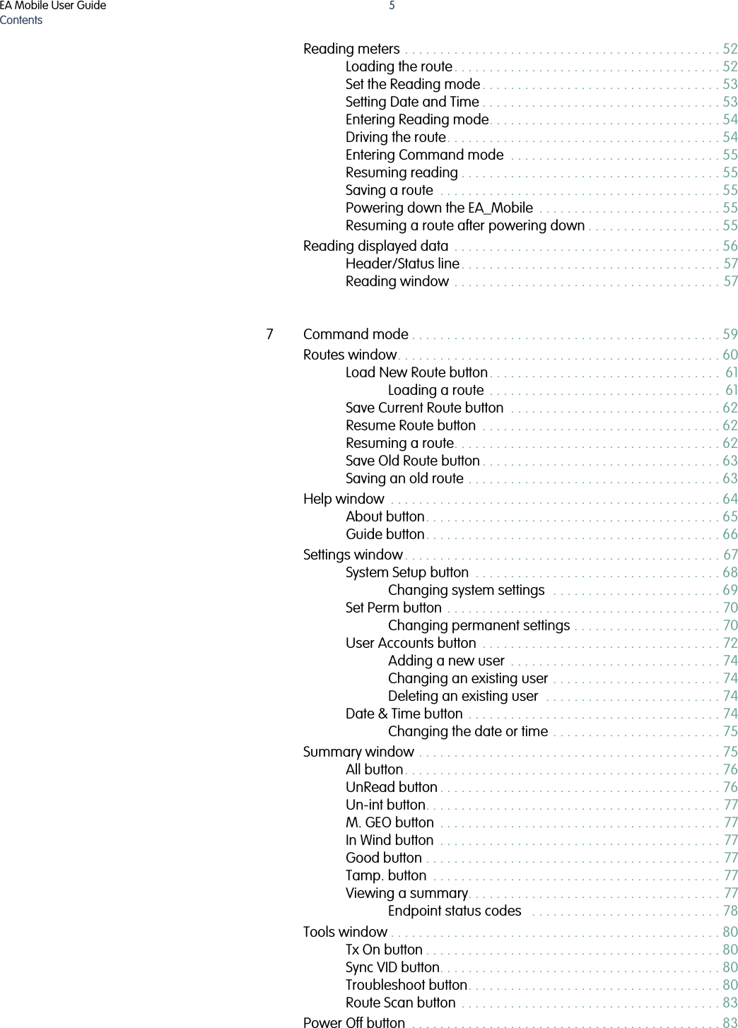


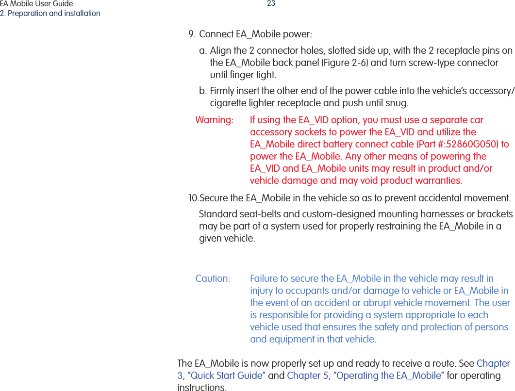
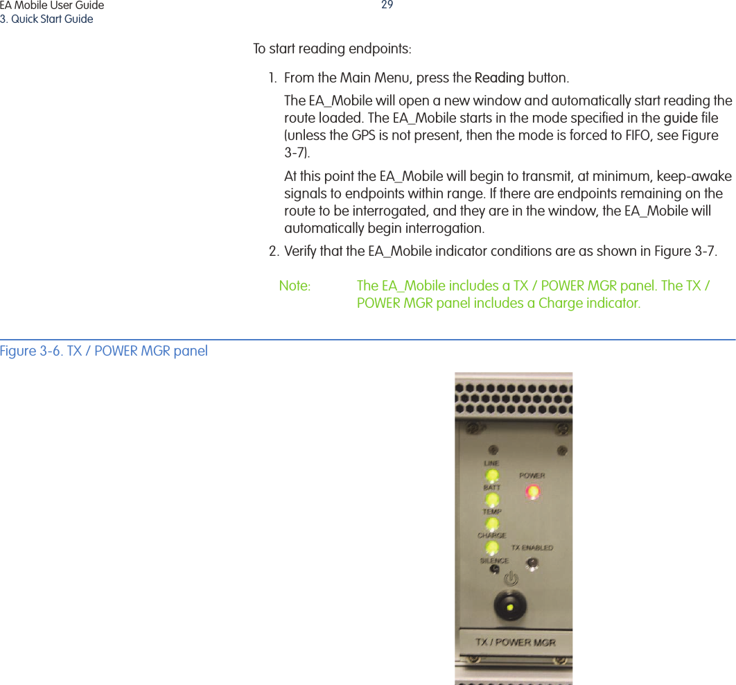
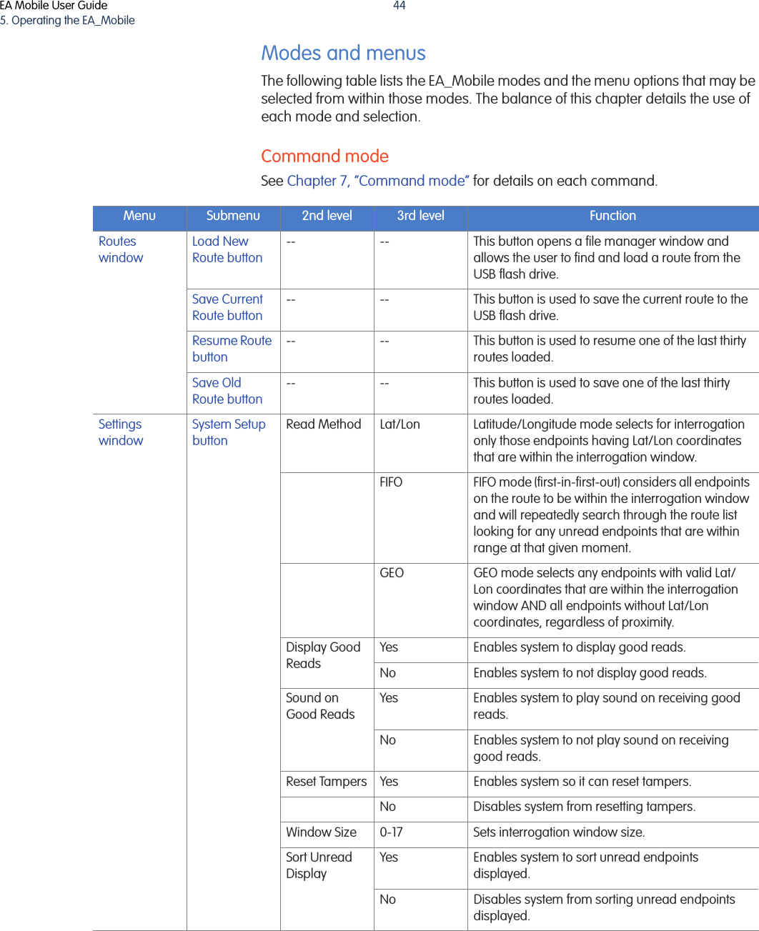
![EA Mobile User Guide3. Quick Start Guide25Operating the EA_Mobile Note: If using the EA_VID, there is no longer a need to load the route on the EA_VID. The EA_Mobile will copy the data to the EA_VID.1. Obtain an HP 4 GB USB flash drive that has been properly loaded with routes created using Elster’s Route Manager for use on the EA_Mobile. Note: All route directories must be the part of the parent directory named TraceVRT. To load the route successfully, each route directory must include the following three files: a Start file, a Guide file, and a Reading.rte file.• The route disk must include the following directory structure if the USB flash drive will be used for multiple routes:• TraceVRT is the top level directory and must be included. •The 0311 directory represents the top route directory for March 2011 (mmYY format). •The 001rte directory will contain all the files necessary for EA_Mobile to interrogate the 001 route. When the route is complete and the Save Current Route button is selected, the 0010311.van file will be stored in the 001rte directory.Note: Ensure that no directory name is longer than 8 characters and that the following characters: ’+’, ’,’’;’ ’=’ ’[’ ’]’ and space are not used in the directory name. Additionally, the ddirectory structure is limited to three levels deep.2. Use the directions detailed in “Installing the EA_Mobile” on page 17 to install the EA_Mobile and the LCD touch screen monitor.3. Insert the HP 4 GB USB flash drive in the socket labelled USB 2 on the EA_Mobile.4. Turn on the EA_Mobile main power switch located on the front panel labeled POWER/AMP MGR.If using an EA_VID, wait a few minutes until the red XMIT status on the EA_VID changes from a ‘?’ to ‘off’, otherwise wait until the monitor displays the EA_Mobile Login Screen.TraceVRT 0311001rteguideReading.rteStart...999rteguideReading.rteStart](https://usermanual.wiki/Elster-Solutions/EAMOBILE1/User-Guide-1872797-Page-25.png)
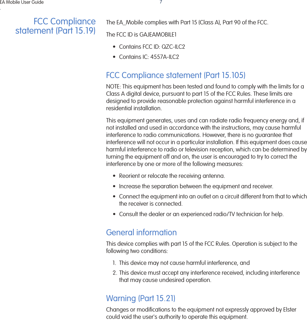
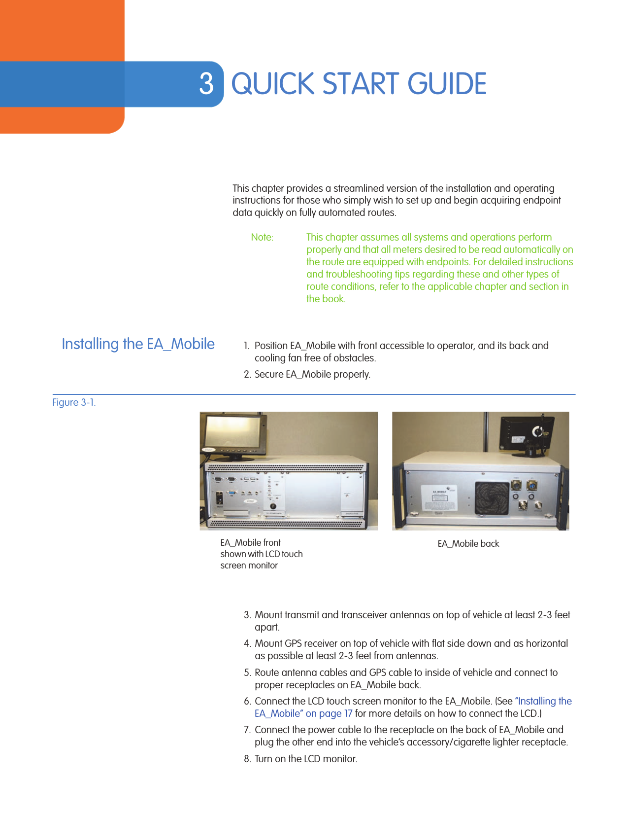
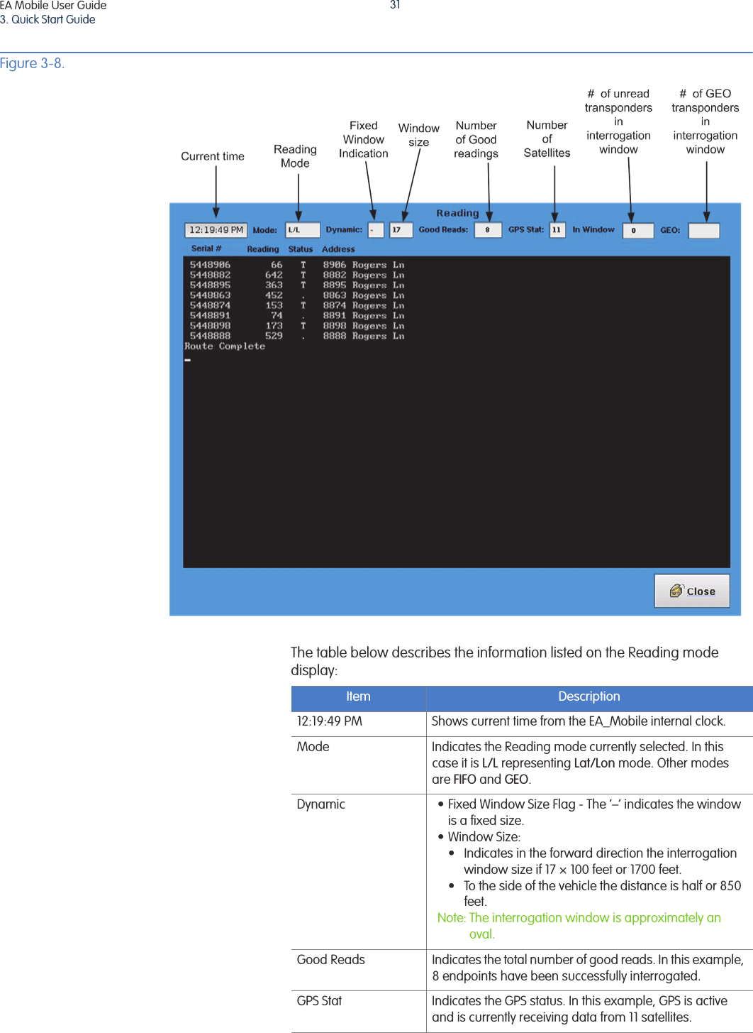
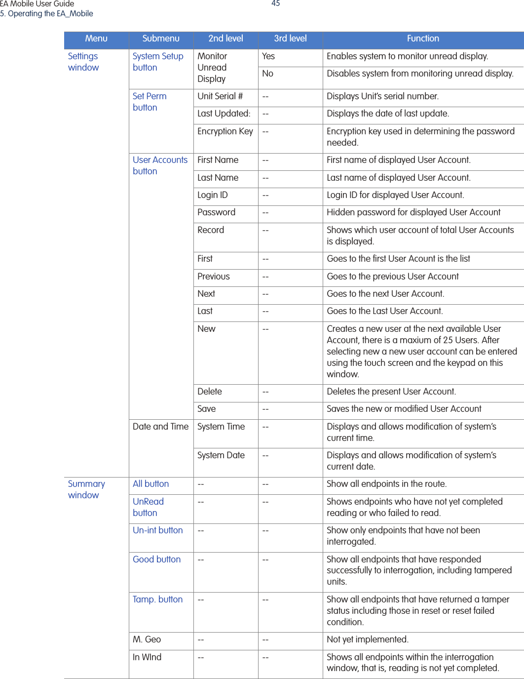
![EA Mobile User Guide3. Quick Start Guide30Figure 3-7. EnergyAxis panelFigure 3-8 shows an example of a Reading mode header. [8] ACTIVITY#Indicator Label Function Start-up Condition1[Alarm] SILENCE button [Not an indicator but a push button] --2CHARGE Battery Charging Status (Power AMP / Mgr.) ON (green or red)3TEMP Temperature status ON (green)4BATT Battery status ON (green)5LINE +12V line status ON (green)6POWER [Next to BATT light] Power status ON (red)7ENABLED TX enabled ON (green)8ACTIVITY Shows transceiver activity OFF (green)](https://usermanual.wiki/Elster-Solutions/EAMOBILE1/User-Guide-1872797-Page-30.png)
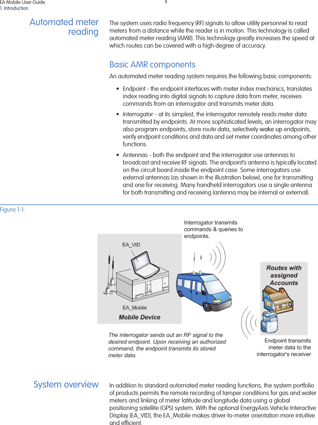
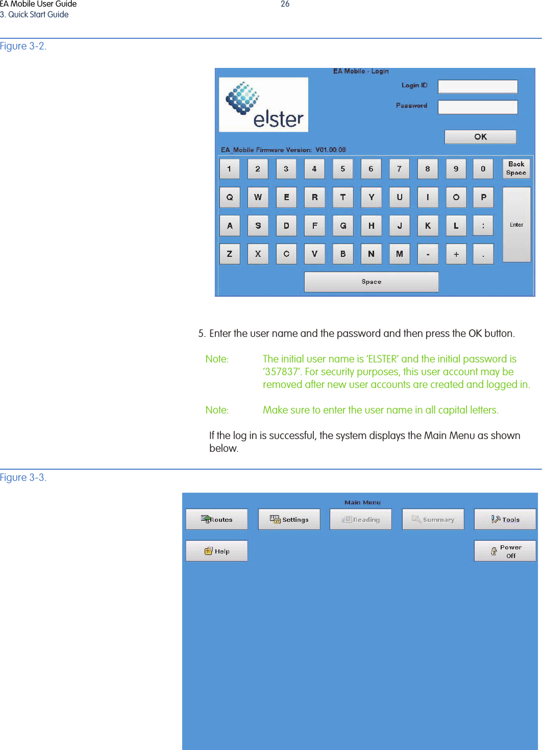
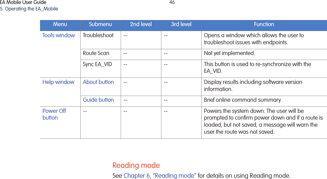
![EA Mobile User Guide3. Quick Start Guide33Figure 3-9. Upon receiving endpoint data, the EA_Mobile will display whatever data it has acquired regarding that particular interrogation attempt including:• Endpoint serial number•Meter reading• Tamper status: • Street addressIf a endpoint replies with tamper code T indicating potential evidence of tampering, the EA_Mobile will automatically attempt to reset the tamper indicator. (You may turn off this option off on the Tools menu.Status Code Meaning• [bullet] Non-tamperedT TamperedR Tamper reset successfulF Tamper reset failed](https://usermanual.wiki/Elster-Solutions/EAMOBILE1/User-Guide-1872797-Page-33.png)

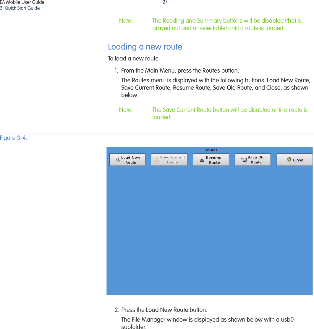
![EA Mobile User Guide4. Controls and indicators37Figure 4-1. TX / POWER MGR panelMain POWER switchThe main Power switch turns on or turns off the 12 Volt power to the EA_Mobile. It is a rocker switch labeled to show the ON and OFF positions.Note: Key numbers shown in brackets [ ] in Figure 4-2 refer to the Key numbers in the table.Familiarize yourself with the normal conditions of these indicators at startup and during interrogation so that any improper conditions will quickly alert you to take action.Caution: Failure to respond to certain improper indications in a timely manner may lead to poor EA_Mobile performance and, in some cases, permanent equipment damage.Table 4-1. TX / Power Mgr. IndicatorsKey Indicator ConditionOptimal t EA_Mobile startupDuring interrogation Warning conditionsError condition1[Alarm] SILENCE button2CHARGE Green Green (when charging)NA Red (when discharging)3TEMP Green Green Yellow Red4BATT Green Green Yellow Red5LINE (+12V) Green Green Yellow Red6POWER Red Red NA Off7ENABLED Off Green NA Off when interrogating](https://usermanual.wiki/Elster-Solutions/EAMOBILE1/User-Guide-1872797-Page-37.png)
![EA Mobile User Guide4. Controls and indicators38Note: As a rule of thumb, all indicator lights except the transmit ENABLED light - should be ON continuously while the EA_Mobile is operating. If the remaining lights are off or flickering, you may need to troubleshoot an error condition. See Appendix A, “Troubleshooting the EA_Mobile” for details.[Alarm] SILENCE buttonAny new alarm condition (also shown by indicator lights) will activate the audible alarm. • If you choose to ignore the problem, you may press the Silence button to silence the alarm. Even after you silence the alarm, however, the indicator light will continue to flash until the actual alarm condition ceases. If the alarm condition persists or recurs, the audible alarm will sound again. CHARGE[Green] Indicates the battery is charging. [Red] Indicates the battery is discharging.TEMP[Green] Indicates the internal temperature of the EA_Mobile is below 130° F. It should be ON continuously whenever the EA_Mobile is powered. If this light is flashing or is Red, it indicates the internal temperature has exceeded the threshold:• Check the cooling fan. Remove any clogs and reposition the EA_Mobile if necessary to ensure adequate air circulation to the cooling fan. • If the fan is operating properly, lower the ambient temperature in the vehicle either by opening windows or by adjusting the heater or air conditioning thermostat.• If the fan is not operating, call Elster’s Service Department. Warning: If the EA_Mobile overheating conditions cannot be corrected immediately, shut down the EA_Mobile. Failure to do so may result in damage to EA_Mobile components.BATT[Green] Indicates the internal battery voltage is stable and adequate to power the EA_Mobile. It should be ON continuously whenever the EA_Mobile is powered. • If this light is flashing, it indicates the EA_Mobile is running on battery power. The internal battery is for temporary emergency use only.Warning: If the BATT light is flashing or is Red, it may indicate the internal battery has dropped to an unusable voltage. Immediately shut down the EA_Mobile!LINE[Green] Indicates the 12 Volt supply from the vehicle’s accessory/cigarette lighter receptacle is delivering adequate voltage to power the EA_Mobile. The LED should be ON continuously whenever the EA_Mobile is powered. If this light is flashing or is Red, it indicates the 12 Volt supply has dropped to an unusable voltage:](https://usermanual.wiki/Elster-Solutions/EAMOBILE1/User-Guide-1872797-Page-38.png)
![EA Mobile User Guide4. Controls and indicators39• Verify the power cable is connected. • Check for vehicle accessories (radio, tape player, CD, etc.) that can be turned off to minimize the power drain. • If the LINE light continues to blink, verify the accessory/cigarette lighter fuse is intact. • If the fuse for the accessory/cigarette lighter has blown, shut down the EA_Mobile and replace the fuse. • If the LINE light continues to blink, the vehicle’s alternator may be unable to produce adequate operating current and should be serviced.POWER[Red] Indicates the +12 Volt power supply to the amplifier is on. It should be ON whenever the EA_Mobile is powered.• If it is not ON, check the fuse and replace if necessary. See “Checking a fuse” on page 41 for details.• If the fuse is OK, contact Elster’s Service Department.ENABLED[Green] Indicates the EA_Mobile transmitter is actively transmitting. The LED should be ON during interrogation or once turned on using the Tools window.• If this light is not ON during interrogation or when transmitter is turned on from the Tools window, contact Elster’s Service Department.EnergyAxis panel indicatorThe EnergyAxis panel is located on the right side of the EA_Mobile front panel (Figure 4-2). The sole indicator is ACTIVITY. This light indicates if serial communications are occurring. This light generally appears as a blinking red or orange. This indicates activity is occurring over the serial communications port.Figure 4-2. EnergyAxis panel[8] ACTIVITY](https://usermanual.wiki/Elster-Solutions/EAMOBILE1/User-Guide-1872797-Page-39.png)
![EA Mobile User Guide4. Controls and indicators40Note: Key numbers shown in brackets [ ] in Figure 4-2 refer to the Key numbers in Table 4-2.ACTIVITYThe activity light indicates if there is activity on the EnergyAxis transceiver antenna.• It will blink Red whenever RS-232 data is received.• It will flicker Green whenever RS-232 data is read from the transceiver.• If the transceiver is both receiving and reading, the Activity indicator will appear as Amber. This includes communication with the transponder and the CPU. This indicator should flicker whenever the EA_Mobile is in reading mode. It’s flickering becomes more solid when transmitting and receiving data from transponders.FusesThe EA_Mobile contains two internal fuses accessed from the back panel (Figure 4-3)FusesFuses. These are standard automotive-type fuses:Figure 4-3. FusesTable 4-2. Receiver (REC) and Transmitter (XMIT) IndicatorsKey Indicator Color ConditionAt EA_Mobile startupWhen EA_Mobile is poweredDuring interrogationError condition8ACTIVITY Red OFF OFF Blinking (Red or Green)OFFInput 20 Amp AGC 32VBattery 20 Amp AGC 32VInputfuseBatteryfuse](https://usermanual.wiki/Elster-Solutions/EAMOBILE1/User-Guide-1872797-Page-40.png)


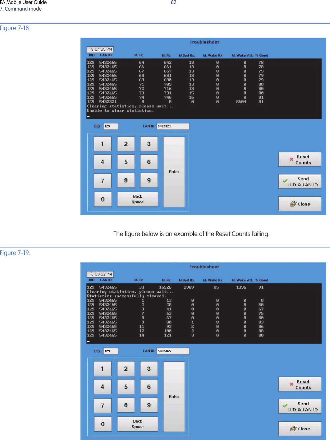
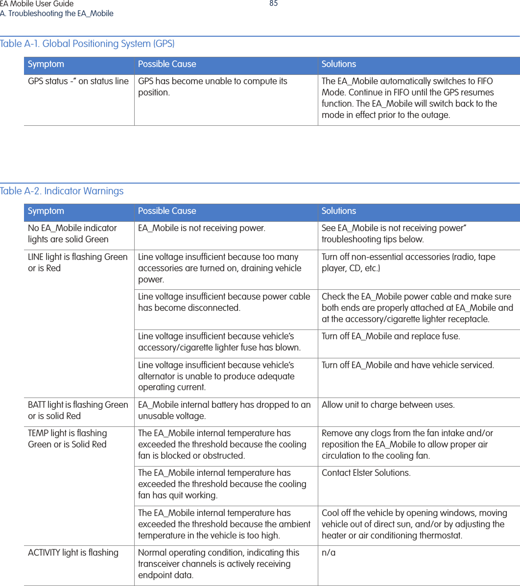
![ATROUBLESHOOTING THE EA_MOBILEThe following table offers troubleshooting assistance for many problems you may encounter. For those symptoms or solutions not covered by this table, contact:ElsterCustomer ServicePhone 800-786-2215 FAX 919-250-5439Business Hours: Monday-Friday 8am-5pm [Eastern Time]Warning: The EA_Mobile contains NO user serviceable parts or adjustment. Tampering with such or breaking tamper seals may prove harmful to personnel or equipment and voids the warranty.Table A-1. Global Positioning System (GPS)Symptom Possible Cause SolutionsGPS not active Insufficient time elapsed since being moved from its last known position and reactivated. GPS requires up to 5 minutes (30 minutes for first time initialization) to achieve maximum satellite communications.Wait 30 minutes or until a minimum of 4 satellites in use, are displayed on handheld terminal or EA_VID. GPS active but not providing good L/L coordinates in FIFO modeInadequate number of satellites for FIFO mode (minimum of 6 required).Wait 30 minutes or until a minimum of 6 satellites in use, are displayed on handheld terminal or EA_VID.GPS active but providing poor L/L readingsInterference is caused by tall buildings, overhanging trees or other obstacles.Continue reading. When coverage resumes, the unit will continue operating in that mode. Receiver is too close to the other antennas Reposition GPS receiver and/or antennas to allow for at least 2 feet separation from the GPS receiver.Loss of GPS signal GPS cable disconnected or improperly connected.Properly connect cable to GPS receptacle on EA_Mobile back.GPS cable crimped or crushed. Reroute cable. If damaged, contact American Meter for replacement unit.Interference is caused by tall buildings, overhanging trees or other obstacles.Continue reading. When coverage resumes, the unit will continue operating in FIFO mode.GPS offline Go to //FIFO or GEO?// mode and continue operating.EA Mobile User Guide](https://usermanual.wiki/Elster-Solutions/EAMOBILE1/User-Guide-1872797-Page-84.png)