Elster Solutions EAMOBILE1 Vehicle-Based Mobile Wireless Meter Reading Equipment User Manual Real Time Mobile Interrogator User Guide
Elster Solutions, LLC Vehicle-Based Mobile Wireless Meter Reading Equipment Real Time Mobile Interrogator User Guide
User Manual

EA_Mobile
for the EnergyAxis®
System
Release 1.0
User Guide
TM42-4025A
11:48 am, Dec 04, 2012

Contents
FCC Compliance statement (Part 15.19) . . . . . . . . . . . . . . . . . . . . . . . . . . . 7
FCC Compliance statement (Part 15.105) . . . . . . . . . . . . . . . . . . . 7
General information . . . . . . . . . . . . . . . . . . . . . . . . . . . . . . . . . . . . 7
Warning (Part 15.21) . . . . . . . . . . . . . . . . . . . . . . . . . . . . . . . . . . . . . 7
1Introduction. . . . . . . . . . . . . . . . . . . . . . . . . . . . . . . . . . . . . . . . . . . . . . . . . . 8
About this book . . . . . . . . . . . . . . . . . . . . . . . . . . . . . . . . . . . . . . . . . . . . . . 8
Audience. . . . . . . . . . . . . . . . . . . . . . . . . . . . . . . . . . . . . . . . . . . . . . 8
Conventions . . . . . . . . . . . . . . . . . . . . . . . . . . . . . . . . . . . . . . . . . . . 8
Automated meter reading . . . . . . . . . . . . . . . . . . . . . . . . . . . . . . . . . . . . . 9
Basic AMR components . . . . . . . . . . . . . . . . . . . . . . . . . . . . . . . . . 9
System overview. . . . . . . . . . . . . . . . . . . . . . . . . . . . . . . . . . . . . . . . . . . . . . 9
How the system works . . . . . . . . . . . . . . . . . . . . . . . . . . . . . . . . . 10
EA_Mobile overview . . . . . . . . . . . . . . . . . . . . . . . . . . . . . . . . . . . . . . . . . .11
Features and functions . . . . . . . . . . . . . . . . . . . . . . . . . . . . . . . . . .11
Interrogator unit . . . . . . . . . . . . . . . . . . . . . . . . . . . . . . . . . 12
GPS receiver . . . . . . . . . . . . . . . . . . . . . . . . . . . . . . . . . . . . 12
Antennas . . . . . . . . . . . . . . . . . . . . . . . . . . . . . . . . . . . . . . 12
Display . . . . . . . . . . . . . . . . . . . . . . . . . . . . . . . . . . . . . . . . 12
Vehicle Interactive Display (optional) . . . . . . . . . . . . . . . . 12
How the EA_Mobile operates . . . . . . . . . . . . . . . . . . . . . . . . . . . . 12
Endpoint selection . . . . . . . . . . . . . . . . . . . . . . . . . . . . . . . 13
Data accuracy verification . . . . . . . . . . . . . . . . . . . . . . . . 13
Meter data acquisition and processing . . . . . . . . . . . . . 13
Route data collection made fast, easy and safe . . . . . . 13
RF signals and conditions . . . . . . . . . . . . . . . . . . . . . . . . . . . . . . . 14
EA_Mobile range . . . . . . . . . . . . . . . . . . . . . . . . . . . . . . . 14
Obstructions . . . . . . . . . . . . . . . . . . . . . . . . . . . . . . . . . . . . 14
Transaction capacity . . . . . . . . . . . . . . . . . . . . . . . . . . . . . 14
Interrogation window . . . . . . . . . . . . . . . . . . . . . . . . . . . . . . . . . . 14
Adjusting interrogation window size . . . . . . . . . . . . . . . 14
Data Processing . . . . . . . . . . . . . . . . . . . . . . . . . . . . . . . . . . . . . . . 15
Maintenance . . . . . . . . . . . . . . . . . . . . . . . . . . . . . . . . . . . . . . . . . . . . . . . 15
Replacement Parts. . . . . . . . . . . . . . . . . . . . . . . . . . . . . . . . . . . . . . . . . . . 15
2 Preparation and installation . . . . . . . . . . . . . . . . . . . . . . . . . . . . . . . . . . . 16
Vehicle requirements. . . . . . . . . . . . . . . . . . . . . . . . . . . . . . . . . . . . . . . . . 16
Unpacking and assembling EA_Mobile components . . . . . . . . . . . . . . 16
Received equipment inventory . . . . . . . . . . . . . . . . . . . . . . . . . . . 17
Unpacking the EA_Mobile. . . . . . . . . . . . . . . . . . . . . . . . . . . . . . . 17
Antennas. . . . . . . . . . . . . . . . . . . . . . . . . . . . . . . . . . . . . . . . . . . . . 17
EnergyAxis transceiver (RX) antenna . . . . . . . . . . . . . . . . 17
Transmit (TX) antenna . . . . . . . . . . . . . . . . . . . . . . . . . . . . 17
Installing the EA_Mobile . . . . . . . . . . . . . . . . . . . . . . . . . . . . . . . . . . . . . . 17
Installing the 7 inch LCD touch screen monitor . . . . . . . . . . . . . . 18
EA Mobile User Guide
EA Mobile User Guide
Contents
4
Option 1 -to a dashboard . . . . . . . . . . . . . . . . . . . . . . . . . 18
Option 2 - to a windshield . . . . . . . . . . . . . . . . . . . . . . . . 19
Connecting the monitor to the EA_Mobile. . . . . . . . . . . . . . . . . . 19
3 Quick Start Guide . . . . . . . . . . . . . . . . . . . . . . . . . . . . . . . . . . . . . . . . . . . . 24
Installing the EA_Mobile . . . . . . . . . . . . . . . . . . . . . . . . . . . . . . . . . . . . . . 24
Operating the EA_Mobile . . . . . . . . . . . . . . . . . . . . . . . . . . . . . . . . . . . . . 25
Loading a new route . . . . . . . . . . . . . . . . . . . . . . . . . . . . . . . . . . . 27
Reading endpoints. . . . . . . . . . . . . . . . . . . . . . . . . . . . . . . . . . . . . 28
Pausing or ending a reading session . . . . . . . . . . . . . . . . . . . . . 34
Resuming a route . . . . . . . . . . . . . . . . . . . . . . . . . . . . . . . 34
4 Controls and indicators . . . . . . . . . . . . . . . . . . . . . . . . . . . . . . . . . . . . . . . 36
Controls and indicators . . . . . . . . . . . . . . . . . . . . . . . . . . . . . . . . . . . . . . . 36
Transmit and power manager controls and indicators. . . . . . . 36
Main POWER switch . . . . . . . . . . . . . . . . . . . . . . . . . . . . . 37
[Alarm] SILENCE button . . . . . . . . . . . . . . . . . . . . . . . . . . . 38
CHARGE . . . . . . . . . . . . . . . . . . . . . . . . . . . . . . . . . . . . . . . 38
TEMP . . . . . . . . . . . . . . . . . . . . . . . . . . . . . . . . . . . . . . . . . . 38
BATT . . . . . . . . . . . . . . . . . . . . . . . . . . . . . . . . . . . . . . . . . . 38
LINE . . . . . . . . . . . . . . . . . . . . . . . . . . . . . . . . . . . . . . . . . . . 38
POWER . . . . . . . . . . . . . . . . . . . . . . . . . . . . . . . . . . . . . . . . 39
ENABLED . . . . . . . . . . . . . . . . . . . . . . . . . . . . . . . . . . . . . . . 39
EnergyAxis panel indicator . . . . . . . . . . . . . . . . . . . . . . . . . . . . . . 39
ACTIVITY . . . . . . . . . . . . . . . . . . . . . . . . . . . . . . . . . . . . . . . 40
Fuses . . . . . . . . . . . . . . . . . . . . . . . . . . . . . . . . . . . . . . . . . . . . . . . . 40
Removing a fuse . . . . . . . . . . . . . . . . . . . . . . . . . . . . . . . . 41
Checking a fuse . . . . . . . . . . . . . . . . . . . . . . . . . . . . . . . . . 41
Replacing a fuse . . . . . . . . . . . . . . . . . . . . . . . . . . . . . . . . 41
Specifications . . . . . . . . . . . . . . . . . . . . . . . . . . . . . . . . . . . . . . . . . . . . . . . 41
5 Operating the EA_Mobile . . . . . . . . . . . . . . . . . . . . . . . . . . . . . . . . . . . . . 42
Accessing EA_Mobile functions . . . . . . . . . . . . . . . . . . . . . . . . . . . . . . . . 42
EA_Mobile modes and menu options . . . . . . . . . . . . . . . . . . . . . . . . . . . 43
Command mode . . . . . . . . . . . . . . . . . . . . . . . . . . . . . . . . . . . . . . 43
Reading mode . . . . . . . . . . . . . . . . . . . . . . . . . . . . . . . . . . . . . . . . 43
Modes and menus . . . . . . . . . . . . . . . . . . . . . . . . . . . . . . . . . . . . 44
Command mode . . . . . . . . . . . . . . . . . . . . . . . . . . . . . . . 44
Reading mode . . . . . . . . . . . . . . . . . . . . . . . . . . . . . . . . . . 46
6Reading mode . . . . . . . . . . . . . . . . . . . . . . . . . . . . . . . . . . . . . . . . . . . . . . 47
Discontinuing reading . . . . . . . . . . . . . . . . . . . . . . . . . . . . . . . . . . 49
Change Reading mode options . . . . . . . . . . . . . . . . . . . . . . . . . . 49
Audible signal . . . . . . . . . . . . . . . . . . . . . . . . . . . . . . . . . . . . . . . . 49
Route Sequence . . . . . . . . . . . . . . . . . . . . . . . . . . . . . . . . . . . . . . . 49
Lat/Lon option. . . . . . . . . . . . . . . . . . . . . . . . . . . . . . . . . . . . . . . . . . . . . . . 49
Establishing Lat/Lon coordinates . . . . . . . . . . . . . . . . . . . . . . . . . 50
Using Lat/Long coordinates . . . . . . . . . . . . . . . . . . . . . . . . . . . . . 50
FIFO option . . . . . . . . . . . . . . . . . . . . . . . . . . . . . . . . . . . . . . . . . . . . . . . . . 50
Assigning endpoint coordinates . . . . . . . . . . . . . . . . . . . . . . . . . 51
GEO option . . . . . . . . . . . . . . . . . . . . . . . . . . . . . . . . . . . . . . . . . . . . . . . . . 51
Assigning coordinates. . . . . . . . . . . . . . . . . . . . . . . . . . . . . . . . . . 51
EA Mobile User Guide
Contents
5
Reading meters . . . . . . . . . . . . . . . . . . . . . . . . . . . . . . . . . . . . . . . . . . . . . 52
Loading the route. . . . . . . . . . . . . . . . . . . . . . . . . . . . . . . . . . . . . . 52
Set the Reading mode . . . . . . . . . . . . . . . . . . . . . . . . . . . . . . . . . . 53
Setting Date and Time . . . . . . . . . . . . . . . . . . . . . . . . . . . . . . . . . . 53
Entering Reading mode. . . . . . . . . . . . . . . . . . . . . . . . . . . . . . . . . 54
Driving the route. . . . . . . . . . . . . . . . . . . . . . . . . . . . . . . . . . . . . . . 54
Entering Command mode . . . . . . . . . . . . . . . . . . . . . . . . . . . . . . 55
Resuming reading . . . . . . . . . . . . . . . . . . . . . . . . . . . . . . . . . . . . . 55
Saving a route . . . . . . . . . . . . . . . . . . . . . . . . . . . . . . . . . . . . . . . . 55
Powering down the EA_Mobile . . . . . . . . . . . . . . . . . . . . . . . . . . 55
Resuming a route after powering down . . . . . . . . . . . . . . . . . . . 55
Reading displayed data . . . . . . . . . . . . . . . . . . . . . . . . . . . . . . . . . . . . . . 56
Header/Status line. . . . . . . . . . . . . . . . . . . . . . . . . . . . . . . . . . . . . 57
Reading window . . . . . . . . . . . . . . . . . . . . . . . . . . . . . . . . . . . . . . 57
7 Command mode . . . . . . . . . . . . . . . . . . . . . . . . . . . . . . . . . . . . . . . . . . . . 59
Routes window. . . . . . . . . . . . . . . . . . . . . . . . . . . . . . . . . . . . . . . . . . . . . . 60
Load New Route button. . . . . . . . . . . . . . . . . . . . . . . . . . . . . . . . . 61
Loading a route . . . . . . . . . . . . . . . . . . . . . . . . . . . . . . . . . 61
Save Current Route button . . . . . . . . . . . . . . . . . . . . . . . . . . . . . . 62
Resume Route button . . . . . . . . . . . . . . . . . . . . . . . . . . . . . . . . . . 62
Resuming a route. . . . . . . . . . . . . . . . . . . . . . . . . . . . . . . . . . . . . . 62
Save Old Route button . . . . . . . . . . . . . . . . . . . . . . . . . . . . . . . . . . 63
Saving an old route . . . . . . . . . . . . . . . . . . . . . . . . . . . . . . . . . . . . 63
Help window . . . . . . . . . . . . . . . . . . . . . . . . . . . . . . . . . . . . . . . . . . . . . . . 64
About button. . . . . . . . . . . . . . . . . . . . . . . . . . . . . . . . . . . . . . . . . . 65
Guide button. . . . . . . . . . . . . . . . . . . . . . . . . . . . . . . . . . . . . . . . . . 66
Settings window . . . . . . . . . . . . . . . . . . . . . . . . . . . . . . . . . . . . . . . . . . . . . 67
System Setup button . . . . . . . . . . . . . . . . . . . . . . . . . . . . . . . . . . . 68
Changing system settings . . . . . . . . . . . . . . . . . . . . . . . . 69
Set Perm button . . . . . . . . . . . . . . . . . . . . . . . . . . . . . . . . . . . . . . . 70
Changing permanent settings . . . . . . . . . . . . . . . . . . . . . 70
User Accounts button . . . . . . . . . . . . . . . . . . . . . . . . . . . . . . . . . . 72
Adding a new user . . . . . . . . . . . . . . . . . . . . . . . . . . . . . . 74
Changing an existing user . . . . . . . . . . . . . . . . . . . . . . . . 74
Deleting an existing user . . . . . . . . . . . . . . . . . . . . . . . . . 74
Date & Time button . . . . . . . . . . . . . . . . . . . . . . . . . . . . . . . . . . . . 74
Changing the date or time . . . . . . . . . . . . . . . . . . . . . . . . 75
Summary window . . . . . . . . . . . . . . . . . . . . . . . . . . . . . . . . . . . . . . . . . . . 75
All button. . . . . . . . . . . . . . . . . . . . . . . . . . . . . . . . . . . . . . . . . . . . . 76
UnRead button . . . . . . . . . . . . . . . . . . . . . . . . . . . . . . . . . . . . . . . . 76
Un-int button. . . . . . . . . . . . . . . . . . . . . . . . . . . . . . . . . . . . . . . . . . 77
M. GEO button . . . . . . . . . . . . . . . . . . . . . . . . . . . . . . . . . . . . . . . . 77
In Wind button . . . . . . . . . . . . . . . . . . . . . . . . . . . . . . . . . . . . . . . . 77
Good button . . . . . . . . . . . . . . . . . . . . . . . . . . . . . . . . . . . . . . . . . . 77
Tamp. button . . . . . . . . . . . . . . . . . . . . . . . . . . . . . . . . . . . . . . . . . 77
Viewing a summary. . . . . . . . . . . . . . . . . . . . . . . . . . . . . . . . . . . . 77
Endpoint status codes . . . . . . . . . . . . . . . . . . . . . . . . . . . 78
Tools window . . . . . . . . . . . . . . . . . . . . . . . . . . . . . . . . . . . . . . . . . . . . . . . 80
Tx On button . . . . . . . . . . . . . . . . . . . . . . . . . . . . . . . . . . . . . . . . . . 80
Sync VID button. . . . . . . . . . . . . . . . . . . . . . . . . . . . . . . . . . . . . . . . 80
Troubleshoot button. . . . . . . . . . . . . . . . . . . . . . . . . . . . . . . . . . . . 80
Route Scan button . . . . . . . . . . . . . . . . . . . . . . . . . . . . . . . . . . . . . 83
Power Off button . . . . . . . . . . . . . . . . . . . . . . . . . . . . . . . . . . . . . . . . . . . . 83
EA Mobile User Guide
Contents
6
A Troubleshooting the EA_Mobile . . . . . . . . . . . . . . . . . . . . . . . . . . . . . . . . 84
B GUI buttons. . . . . . . . . . . . . . . . . . . . . . . . . . . . . . . . . . . . . . . . . . . . . . . . . 88
Notes on GUI buttons . . . . . . . . . . . . . . . . . . . . . . . . . . . . . . . . . . . . . . . . 88
EA Mobile User Guide
.
7
FCC Compliance
statement (Part 15.19)
The EA_Mobile complies with Part 15 (Class A), Part 90 of the FCC.
The FCC ID is GAJEAMOBILE1
• Contains FCC ID: QZC-ILC2
• Contains IC: 4557A-ILC2
FCC Compliance statement (Part 15.105)
NOTE: This equipment has been tested and found to comply with the limits for a
Class A digital device, pursuant to part 15 of the FCC Rules. These limits are
designed to provide reasonable protection against harmful interference in a
residential installation.
This equipment generates, uses and can radiate radio frequency energy and, if
not installed and used in accordance with the instructions, may cause harmful
interference to radio communications. However, there is no guarantee that
interference will not occur in a particular installation. If this equipment does cause
harmful interference to radio or television reception, which can be determined by
turning the equipment off and on, the user is encouraged to try to correct the
interference by one or more of the following measures:
• Reorient or relocate the receiving antenna.
• Increase the separation between the equipment and receiver.
• Connect the equipment into an outlet on a circuit different from that to which
the receiver is connected.
• Consult the dealer or an experienced radio/TV technician for help.
General information
This device complies with part 15 of the FCC Rules. Operation is subject to the
following two conditions:
1. This device may not cause harmful interference, and
2. This device must accept any interference received, including interference
that may cause undesired operation.
Warning (Part 15.21)
Changes or modifications to the equipment not expressly approved by Elster
could void the user's authority to operate this equipment.
EA Mobile User Guide

1INTRODUCTION
The EA_Mobile is the most robust interrogator in Elster’s portfolio of products for
remote and automated meter reading (AMR). The EA_Mobile has numerous
features and functions not available with smaller, handheld devices and yet is
versatile enough to be moved from vehicle to vehicle, wherever and whenever it
is needed.
About this book This EA_Mobile User Guide provides instructions for setup, installation, operation
and troubleshooting the EA_Mobile. It is structured for use as an adjunct to
system training, as well as a standalone instruction guide and reference.
Audience
This document is designed for utility industry meter readers and supervisory staff.
In order to establish appropriate levels of detail for the material, this document
assumes the following:
• The user is experienced in reading meters of the type currently compatible
with endpoints and possesses all the skills necessary to conduct meter
reading by conventional means.
• The user has little or no prior expertise with AMR technology.
• The user is competent in the basic use of computer equipment and
software.
• The user is familiar with geographic positioning concepts such as latitude
and longitude.
Conventions
In the interest of brevity and simplicity, this document uses the following
conventions:
• Additional information relevant to a given instruction step may be shown in
one of three ways:
• a numbered or bulleted item covers how-to and verification information.
•a NOTE contains relevant background information.
•a blue CAUTION contains information important to the safety of either the
user or the equipment.
•a red WARNING contains information critical to the safety of people and/
or equipment.
• Where reference to other parties is made, the generic masculine pronouns
(he, his, and him) are used. This is no way reflects bias or gender
discrimination in any manner related to the users, publishers or authors of
this book.
EA Mobile User Guide
EA Mobile User Guide
1. Introduction
9
Automated meter
reading
The system uses radio frequency (RF) signals to allow utility personnel to read
meters from a distance while the reader is in motion. This technology is called
automated meter reading (AMR). This technology greatly increases the speed at
which routes can be covered with a high degree of accuracy.
Basic AMR components
An automated meter reading system requires the following basic components:
• Endpoint - the endpoint interfaces with meter index mechanics, translates
index reading into digital signals to capture data from meter, receives
commands from an interrogator and transmits meter data.
• Interrogator - at its simplest, the interrogator remotely reads meter data
transmitted by endpoints. At more sophisticated levels, an interrogator may
also program endpoints, store route data, selectively wake up endpoints,
verify endpoint conditions and data and set meter coordinates among other
functions.
• Antennas - both the endpoint and the interrogator use antennas to
broadcast and receive RF signals. The endpoint’s antenna is typically located
on the circuit board inside the endpoint case. Some interrogators use
external antennas (as shown in the illustration below), one for transmitting
and one for receiving. Many handheld interrogators use a single antenna
for both transmitting and receiving (antenna may be internal or external).
Figure 1-1.
System overview In addition to standard automated meter reading functions, the system portfolio
of products permits the remote recording of tamper conditions for gas and water
meters and linking of meter latitude and longitude data using a global
positioning satellite (GPS) system. With the optional EnergyAxis Vehicle Interactive
Display (EA_VID), the EA_Mobile makes driver-to-meter orientation more intuitive
and efficient.
EA Mobile User Guide
1. Introduction
10
EA_Gas module and EA_Water module endpoints that are normally in a sleep
mode to conserve battery power wake up and periodically listen for an
interrogation signal. These endpoints will transmit data back to the interrogation
device only if it hears its unique ID and specified command and then it goes back
to sleep. REX2 and A3 ALPHA electricity meters have AC power sources and do
not require wake-up; they respond to the interrogation request without a wake-
up.
How the system works
Utility personnel no longer have to walk up to each meter, look at its index and
record its reading. Once endpoints are installed on meters and programmed,
meter readers simply drive a route allowing the interrogator to request and
record meter data automatically.
Figure 1-2.
Acquisition of meter information begins with the endpoint where data is stored
continuously for later retrieval and is received by the interrogator when
requested. The acquired data from a given route can be transferred to a host
computer via the supplied HP 4 GB USB flash drive for processing.
The information acquisition, storage and handling process includes several basic
elements:
Meter interface The gas and water endpoint, using a mechanical-to-
digital interface, senses the output from the index of a
utility meter and translates this into electronic form and
stores it in the endpoint’s memory. Electricity meters
measure the kilowatts used and store this usage data in
the endpoint’s memory.

EA Mobile User Guide
1. Introduction
11
EA_Mobile overview The EA_Mobile is a portable data retrieval and storage system designed to
provide remote meter reading of mechanical indexes via meter endpoints.
The EA_Mobile is designed for use in vehicles for fast, accurate automated meter
reading at maximum range and at normal residential driving speeds.
Caution: Use only automatic EA_Mobile operation while the vehicle is in
motion. To change EA_Mobile settings or view data, safely
move the vehicle off the roadway and park in a secure location.
Features and functions
The EA_Mobile along with several primary components is transported in a
wheeled case. Those components are:
• EA_Mobile interrogator unit
• GPS receiver
• Transmitting antenna
• EnergyAxis transceiver antenna
• LCD touch screen display
• Power supply cable
Endpoint data acquisition The endpoint is programmed with a unique serial
number at the time of manufacture. Upon installation on
a meter, the current (or baseline) meter index reading is
also programmed into the endpoint’s memory. As the
meter reading advances it automatically updates the
endpoint memory. For gas and water meters, the
endpoint also records changes to the tamper detection
sensor.
Compensation factor For gas and water endpoints, a compensation factor can
also be programmed into the endpoint memory ensuring
the endpoint readings match the compensated
mechanical index reading.
Route information loading Route data includes the meter account number, address,
latitude/longitude coordinates (when available), and
endpoint serial number. This information, along with
Guide and Start files, is downloaded to the interrogator
prior to commencing automated meter reading. By
tracking the vehicle or interrogator’s coordinates, a GPS-
equipped system determines which endpoints in the
route are within range at any given time and transmits
those serial numbers requesting meter data.
Interrogation Once placed in an interrogation mode by the meter
interrogator; the interrogator transmits serial numbers of
the desired endpoints along with a command requesting
the contents of each endpoint’s memory. Endpoints are
selected for reading on the basis of route and meter
location information stored in the interrogator and
presence of the endpoint within range of the interrogator.
Route data processing Meter data from endpoints is stored in the interrogator’s
memory and can be transferred to the utility’s host
computer for processing.

EA Mobile User Guide
1. Introduction
12
Note: Optional EA_VID is shipped separately.
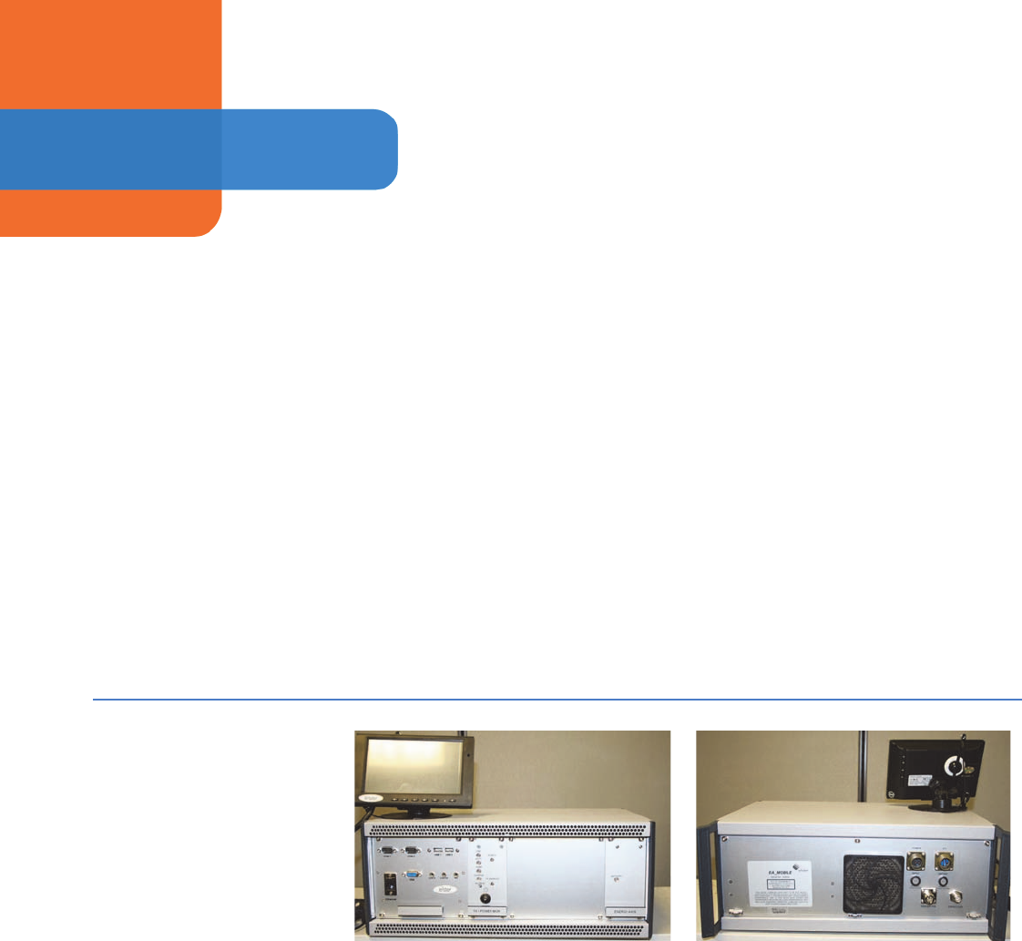
Interrogator unit
The interrogator unit is the heart of the EA_Mobile, containing within its rugged
case these core components:
• Wake-up transmitter
• EnergyAxis transceiver module
• Power supply (backup)
• Computer - CPU (microprocessor)
• Connection receptacles, controls and indicators
Figure 1-3.
GPS receiver
The EA_Mobile interfaces with a Global Positioning Satellite (GPS) system to
provide data, including latitude and longitude information for the interrogator/
vehicle (the data can be used to determine the location of the vehicle and
determine if meter endpoints are within the interrogation window).
Antennas
The EA_Mobile employs separate transmit wake-up and transceiver antennas for
faster acquisition of endpoint data.
Display
The user interface for the EA_Mobile is accomplished via a 7 inch LCD Monitor
with Touch Screen.
Vehicle Interactive Display (optional)
The EnergyAxis Vehicle Interactive Display (EA_VID) (installed on a ruggedized
laptop computer) is an optional graphical user interface (GUI) terminal for the
EA_Mobile that provides a more visual and intuitive means to interact with the
EA_Mobile and view information.
How the EA_Mobile operates
1. On power up, the EA_Mobile will turn off the transmitter.
2. The user plugs in the HP 4 GB USB flash drive, from which a route can be
selected and loaded.
Front view Back view

EA Mobile User Guide
1. Introduction
13
3. Once the route is loaded the reading mode can be entered. In reading
mode the interrogator issues the necessary commands to interrogate the
endpoints while the user drives along the route with the EA_Mobile
operating.
4. The EA_Mobile sends out an interrogation signal searching for the
endpoints that are determined to be within its current interrogation window.
5. When a endpoint receives a signal with its unique ID and specific command,
the endpoint replies by transmitting the requested data (transmitted data
depends on the type of meter).
Endpoint selection
Endpoints can be queued for reading by the EA_Mobile according to three types
of criteria:
Data accuracy verification
The EA_Mobile uses a module to preform RF communication using the EA_LAN
protocol. The EA_Gas module and the EA_Water module use various methods for
error detection including a check sum algorithm.
Meter data acquisition and processing
When the data stream from a endpoint meets the above criteria for accuracy, the
EA_Mobile records the meter index reading along with endpoint status, time and
the vehicle position at the time of the read. If desired, this data can be stored in an
output file on the supplied HP 4GB USB flash drive. At the end of a shift or upon
terminating data collection for a particular route, the HP 4GB USB flash drive is
removed for later use or for further processing by the utility.
Route data collection made fast, easy and safe
Once the EA_Mobile is initialized with the proper route data and the interrogation
command is given by the user, the system will collect readings automatically, with
little or no further intervention from the meter reader as the user drives the
Proximity to EA_Mobile (Lat/
Lon mode)
All endpoints with Lat/Lon coordinates within range of the
EA_Mobile are polled until readings are obtained. This is
the most efficient reading method because the
EA_Mobile only attempts to read endpoints that are
within its range. (Endpoints without Lat/Lon coordinates
cannot be read in Lat/Lon mode.) The EA_Mobile limits
route files to 50176 lines when in this mode.
Sequential (FIFO mode) The FIFO, or first-in-first-out, method simply means the
EA_Mobile will begin at the top of the route list,
continuously searching for all unread endpoints on the
list. As the route is covered and endpoints reply to the
interrogation signal with valid data, the list becomes
shorter. This is the least efficient reading method because
the EA_Mobile may be polling endpoints that are out of
range. The EA_Mobile limits routes to 300 endpoints
when in this mode.
Combination (GEO mode) GEO mode is a combination of Lat/Lon and FIFO. If a
endpoint has Lat/Lon coordinates, the EA_Mobile will
attempt to read this unit ONLY if it is currently within the
interrogation window. All endpoints without Lat/Long
coordinates are constantly polled until readings are
obtained. The EA_Mobile limits the number of endpoints
without Lat/Lon coordinates (GEO transponders) to 100.
EA Mobile User Guide
1. Introduction
14
specified route. The EA_Mobile can be set to give an audible signal upon
acquiring meter data so that the driver never has to take his eyes off the road
while the vehicle is in motion.
RF signals and conditions
EA_Mobile range
As a rule, residential gas endpoints within a line-of-sight distance of
approximately 1200 feet of the EA_Mobile should be able to receive interrogation
signals and respond appropriately when the EA_Mobile is in FIFO mode (Note:
the line-of-sight distance for water endpoints may vary based on installation
parameters). In GEO or L/L mode interrogations are limited to the size of the
window. Certain fixed or transient conditions in the immediate environment
surrounding the endpoint or EA_Mobile may increase or reduce this range.
Obstructions
Line-of-sight (no obstructions between the EA_Mobile antennas and the
endpoint) provides the optimum transaction range. Although the EA_Mobile can
typically read endpoints through walls and fences, any obstacles between the
EA_Mobile and the endpoint will reduce the range at which successful
communications may be conducted. Metallic obstacles (vehicles, trash cans,
metal sheds, etc.) in the path will severely limit interrogation range.
Transaction capacity
The EA_Mobile can interrogate one EA_Gas module endpoint a second,
retrieving 35 daily reads in addition to the current read in extremely dense
populations under ideal conditions.
Interrogation window
The interrogation window is a virtual space that simply defines which endpoints
the EA_Mobile will seek to read at any given time. Depending upon the selected
reading mode, the interrogation window may include:
• Endpoints having Lat/Lon coordinates that are determined to be within the
interrogation window of the EA_Mobile at the moment (Lat/Lon mode).
• All endpoints, regardless of Lat/Lon coordinates or proximity to the
EA_Mobile (FIFO mode).
• A combination of the above, seeking those Lat/Lon endpoints determined to
be within the interrogation window at the moment and in addition also
seeking all endpoints without Lat/Lon coordinates regardless of proximity to
the EA_Mobile (GEO mode).
Adjusting interrogation window size
The user can manually increase or decrease the interrogation window in order to
change the scope of the EA_Mobile’s search for endpoints. A smaller
interrogation window would be desirable, for example, in urban areas where the
endpoint population is extremely dense. In rural areas where endpoints are few
and far between, a larger Interrogation window may be used to detect endpoints
at a greater distance.

EA Mobile User Guide
1. Introduction
15
Data Processing
At the end of a route, data acquired automatically by the EA_Mobile can be
saved to a HP 4 GB USB flash drive disk for transfer to the utility company’s host
computer for administrative processing.
Maintenance The EA_Mobile has no user-serviceable parts.
Replacement Parts Below is a list of the replacement parts that can be ordered from Elster.
Caution: Only use the USB drive provides by Elster.
Item Part Name Quantity Part #
1 EA_Mobile Transmitter Antenna – 28
inches
1 40811 G001
2 EA_Mobile Transceiver Antenna – 12
inches
1 1B11917G01
3 EA_Mobile GPS Receiver 1 52860K001
4 EA_Mobile Power Cord (Optional) 1 52860K002
5 HP 4 GB USB flash drive 1 7S1969 H001
6 Direct Battery Cable Assembly
(recommended option)
1 52860G050
7 Monitor, Xenarc 705 series 7 inch LCD
Monitor with USB Touch Screen
(Required when NOT using EA_VID)
1 7S1911 H001
8 Adhesive, dashboard mount for the
touch screen.
Note: Required when NOT using the
EA_VID.
1 7S1941 H002
9 Suction, wind-shield mount for the
touch screen. (Optional)
1 7S1941 H001
10 Cable, Xenarc 26 pin input
Note: Required when NOT using the
EA_VID.
1 7S1978 H001
11 Cigarette lighter Cable, Xenarc 12V
DC
Note: Required when NOT using the
EA_VID.
1 7S1977 H001
14 Cable, CAT5e, Crossover,6’
.(Only required when using EA_VID)
1 7S1943 H001
2PREPARATION AND
INSTALLATION
This section details the procedures for unpacking the EA_Mobile, assembling its
components and installing them in and on your selected vehicle. This section also
specifies EA_Mobile requirements, conditions and cautions.
Vehicle requirements The EA_Mobile typically uses 100 Watts of power (8 Amps current) and is powered
by a vehicle’s standard 13.8 Volt electrical systems using the direct battery
connection cable (recommended configuration). If the optional outlet power cable
is used, the vehicle accessory outlet should be rated for 20 Amps continuous.
Operating the EA_Mobile with the optional EA_VID requires a separate accessory
outlet for each device.
Unpacking and
assembling EA_Mobile
components
When you receive the EA_Mobile, it will contain all components inside a single,
hard-shelled case that has wheels on the bottom and a handle on top for easy
transport.
Note: The optional EA_VID is shipped separately.
Figure 2-1.
EA Mobile User Guide
EA Mobile User Guide
2. Preparation and installation
17
EA_Mobile unpacking and set-up will take about five minutes using the
procedure described below. No special tools are required.
Received equipment inventory
The EA_Mobile is shipped with the following components inside its case:
• Interrogator unit (transceiver, CPU, USB flash drive, etc.)
• EA_Mobile-to-vehicle power cable and connector
• GPS receiver, cable and connector
• Transmit antenna, cable and connector
• EnergyAxis transceiver antenna, cable and connector
• 7 inch LCD touch screen and connector cables
Note: The optional EA_VID is shipped separately.
Unpacking the EA_Mobile
The EA_Mobile wheeled carrying case contains all the basic EA_Mobile
equipment and materials listed above.
1. Set the carrying case on a sturdy flat surface with the wheels and sliding tow
handle on the bottom.
2. Remove any locks that may have been attached for security purposes.
3. Release both latches and open the case.
4. Remove the handheld touch screen from the top of the EA_Mobile unit.
5. Remove the cables and antennas from beside the EA_Mobile.
6. Lift the EA_Mobile unit from the case and remove the packing wrap.
7. Leave packing materials in the case for future use and stow the case in a
secure location.
Antennas
Antennas are fully assembled and can not be disassembled
Caution: Attempting to disassemble antennas with black Mag from
mount bases will cause damage to the antennas and possibly
to the EA_Mobile.
EnergyAxis transceiver (RX) antenna
Screw-in BNC connector.
Transmit (TX) antenna
Screw-in N connector.
Installing the EA_Mobile This section describes the procedure for installing the EA_Mobile and
components in the selected vehicle.
EA Mobile User Guide
2. Preparation and installation
18
Caution: The EA_Mobile base unit contains sensitive electronic
components. Handle with care and do not drop. Use carrying
case to transport the EA_Mobile wherever possible.
1. Verify the vehicle requirements (see “Vehicle requirements” on page 16) are
met.
2. Place the EA_Mobile unit in the vehicle:
• Set the EA_Mobile on a passenger seat or on any other firm and
reasonably level surface where it will not interfere with the vehicle’s
operation yet is accessible to the user.
• Situate the EA_Mobile with its front toward the user/driver and its back
and cooling fan away from any objects or surfaces that might impede air
flow.
Caution: Failure to provide adequate cooling can cause EA_Mobile to
overheat, which can damage components.
• Position the front panel so that the operator can view the indicator lights
and access the USB flash drive when the vehicle is parked.
Caution: The EA_Mobile should only be used for automated functions
when the vehicle is in motion. To interact with the EA_Mobile,
the user must first stop and park the vehicle safely off the
roadway.
Installing the 7 inch LCD touch screen monitor
You can select to install the 7-inch LCD monitor in either of the following positions:
•Option 1 -to a dashboard
•Option 2 - to a windshield
Note: The suction mount needed to install the LCD monitor is an
optional component and, if required, must be ordered
separately.
If you are using a suction windshield mount instead of the adhesive, dashboard
mount, see “Option 2 - to a windshield” on page 19.
Option 1 -to a dashboard
Note: Elster recommends mounting the 7 inch LCD touch screen
monitor onto the dashboard.
To mount the monitor to the dashboard:
1. Mount the LCD monitor to its dashboard holder by sliding the monitor into
the mounting stand and then secure the height position by adjusting the
knob.
• Choose an area near the driver’s side dashboard for the mount.
• Make sure the area does not block the driver’s view of the road when the
touch screen monitor is installed.
• Position the holder in such a way so when the monitor is installed, the
monitor can be easily reached by the operator when the vehicle is safely
parked.

EA Mobile User Guide
2. Preparation and installation
19
• Use an area below the driver’s line of sight
2. Clean the selected location.
3. Remove the adhesive cover from the holder’s base and securely mount the
holder and the monitor on the selected location of the dashboard.
Option 2 - to a windshield
1. Mount the LCD monitor to its suction windshield holder by sliding monitor
into the mounting stand, then, secure the height position by adjusting knob.
• Choose an area near the driver’s side windshield for the mount.
• Make sure the area does not block the driver’s view of the road when the
touch screen monitor is installed.
• Position the holder in such a way so when monitor installed, the monitor
can be easily reached by the operator when the vehicle is safely parked.
• Use an area below the driver’s line of sight, close to the dashboard.
2. Clean the selected location with the glass cleaner.
3. Remove the protecting film covering the suction cup.
4. Press the suction cup against the flat area of the selected location and use
the release lever to secure the holder.
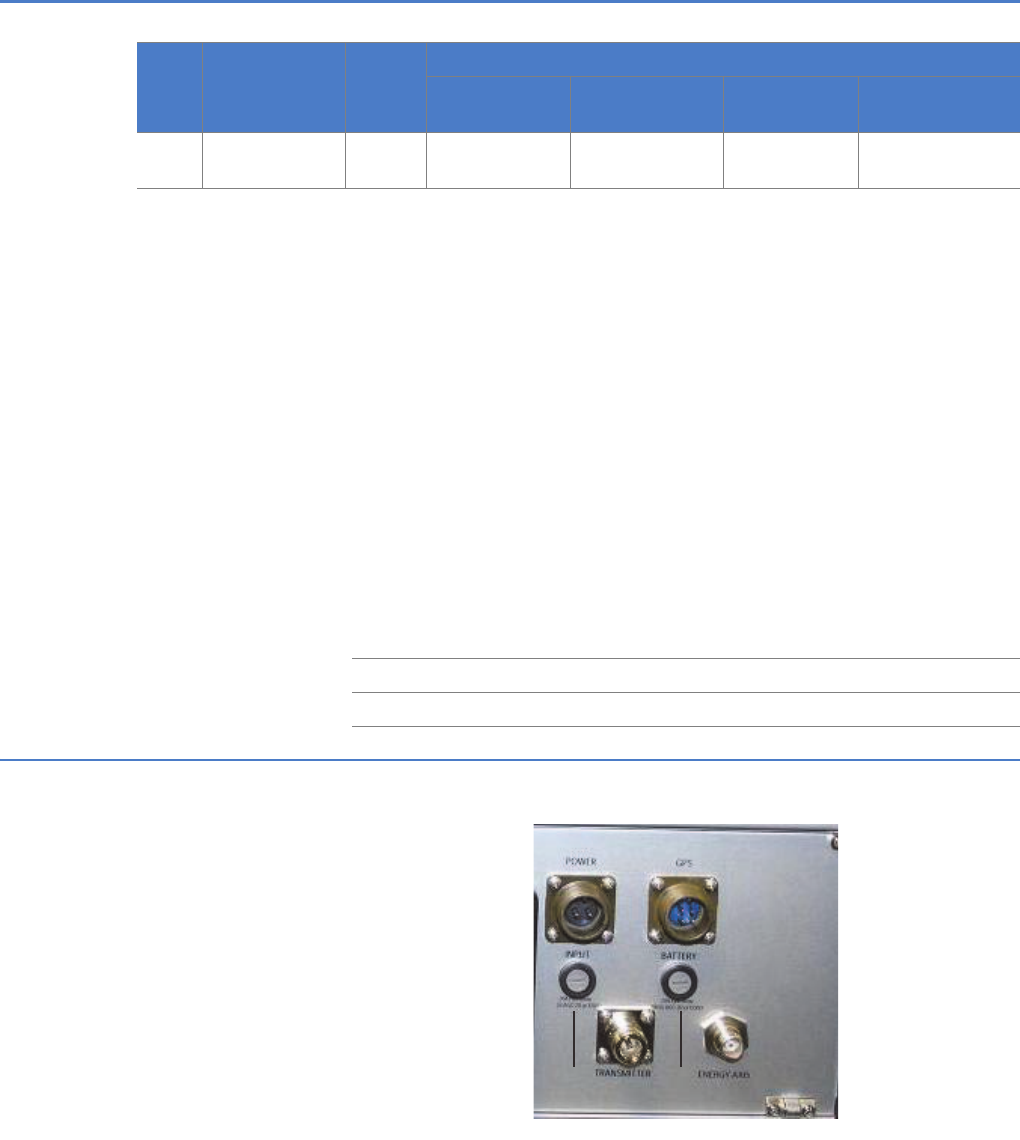
Connecting the monitor to the EA_Mobile
To connect the touch screen monitor with the EA_Mobile after mounting the
monitor on the dashboard or on the windshield:
1. Connect the power cable to the POWER receptacle on the back of the
monitor (Figure 2-2).
Figure 2-2. EA_Mobile back panel
2. Have a certified vehicle mechanic connect the other end of the direct
connect power cable to the vehicle’s battery post.
3. Connect the LCD monitor to the EA_Mobile by connecting the VGA, Line Out
and USB 1 into the corresponding sockets on the EA_Mobile front panel as
shown in Figure 2-3.
EA Mobile User Guide
2. Preparation and installation
20
Figure 2-3. EA_Mobile front panel
Caution: The monitor must be connected before powering up the
EA_Mobile for the touch screen to function correctly.
4. Install the antennas, including GPS, on the roof of the vehicle (as shown in
Figures 2-4 and 2-5).
Caution: Use of antennas other than those supplied with the EA_Mobile
or improperly connected antennas may result in reduced
performance and/or EA_Mobile damage. Use of unauthorized
antennas will void your warranty.
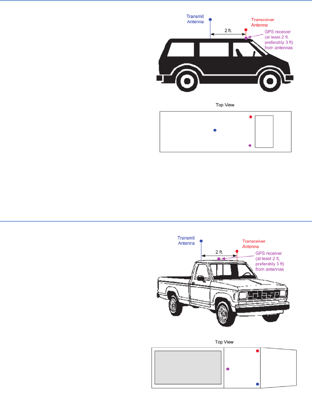
• Position the antennas so they are separated by a minimum of 2 feet.
• Antennas should also be placed a minimum of 2 feet from the edge of
the vehicle or metal surface.
The transceiver antenna should be place as close to the front edge of the
vehicle as possible to get the antenna nearly vertical.
The figures below show the ideal placement of antennas mounted on
roof of a mini van and pickup. Vehicles with larger roof area can provide
greater antenna separation.
EA Mobile User Guide
2. Preparation and installation
21
Figure 2-4. Placement of GPS receiver and RF antennas (van or SUV)
a. Place the transceiver antenna on the roof of the vehicle near the front and
secure its magnetic mount to the roof.
b. Place the transmit antenna on the roof of the vehicle near the back and
secure its magnetic mount to the roof.
See the figure below for recommended mounting configuration on a pickup truck.
Figure 2-5. Placement of GPS receiver and RF antennas (truck)

EA Mobile User Guide
2. Preparation and installation
22
5. Route both antenna coaxial cables to the inside of the vehicle, preferably
from the passenger side.
Caution: Ensure routing method secures cables without crimping or
crushing and provides proper safety for occupants and
equipment.
6. Mount the GPS receiver on the front right for a van or the back middle for a
truck:
a. Attach the GPS receiver to the roof using the magnetic mount on the flat
(bottom) side of the receiver.
b. For optimal satellite reception, mount the receiver with the flat side down
and as nearly horizontal as possible.
c. To minimize interference to and from antennas, mount GPS at least 2 to 3
feet away from antennas.
7. Route the GPS receiver cable to the inside of the vehicle.
Caution: Ensure cable routing method secures cable without crimping or
crushing and provides proper safety for occupants and
equipment.
Figure 2-6.
8. Connect the antennas and GPS receiver cables to the EA_Mobile (see Figure
2-6):
a. Connect transmitter antenna to the TRANSMITTER receptacle on the
EA_Mobile back panel by turning the screw-type connector until finger-
tight.
b. Connect the Transceiver antenna to toe EnergyAxis receptacle on the
EA_Mobile back panel by aligning the pin and pushing the coax
connector on and twisting it ¼ turn until locked in placed.
c. Connect the GPS receiver by aligning the 4 connector holes, slotted side
up, with the 4 GPS receptacle pins on the EA_Mobile back panel and turn
screw-type connector until finger tight.
Warning: Do not block air flow to the EA_Mobile cooling fan located on
the back panel to the left of the power connector.
EA Mobile User Guide
2. Preparation and installation
23
9. Connect EA_Mobile power:
a. Align the 2 connector holes, slotted side up, with the 2 receptacle pins on
the EA_Mobile back panel (Figure 2-6) and turn screw-type connector
until finger tight.
b. Firmly insert the other end of the power cable into the vehicle’s accessory/
cigarette lighter receptacle and push until snug.
Warning: If using the EA_VID option, you must use a separate car
accessory sockets to power the EA_VID and utilize the
EA_Mobile direct battery connect cable (Part #:52860G050) to
power the EA_Mobile. Any other means of powering the
EA_VID and EA_Mobile units may result in product and/or
vehicle damage and may void product warranties.
10.Secure the EA_Mobile in the vehicle so as to prevent accidental movement.
Standard seat-belts and custom-designed mounting harnesses or brackets
may be part of a system used for properly restraining the EA_Mobile in a
given vehicle.
Caution: Failure to secure the EA_Mobile in the vehicle may result in
injury to occupants and/or damage to vehicle or EA_Mobile in
the event of an accident or abrupt vehicle movement. The user
is responsible for providing a system appropriate to each
vehicle used that ensures the safety and protection of persons
and equipment in that vehicle.
The EA_Mobile is now properly set up and ready to receive a route. See Chapter
3, “Quick Start Guide” and Chapter 5, “Operating the EA_Mobile” for operating
instructions.
3QUICK START GUIDE
This chapter provides a streamlined version of the installation and operating
instructions for those who simply wish to set up and begin acquiring endpoint
data quickly on fully automated routes.
Note: This chapter assumes all systems and operations perform
properly and that all meters desired to be read automatically on
the route are equipped with endpoints. For detailed instructions
and troubleshooting tips regarding these and other types of
route conditions, refer to the applicable chapter and section in
the book.
Installing the EA_Mobile 1. Position EA_Mobile with front accessible to operator, and its back and
cooling fan free of obstacles.
2. Secure EA_Mobile properly.
Figure 3-1.
3. Mount transmit and transceiver antennas on top of vehicle at least 2-3 feet
apart.
4. Mount GPS receiver on top of vehicle with flat side down and as horizontal
as possible at least 2-3 feet from antennas.
5. Route antenna cables and GPS cable to inside of vehicle and connect to
proper receptacles on EA_Mobile back.
6. Connect the LCD touch screen monitor to the EA_Mobile. (See “Installing the
EA_Mobile” on page 17 for more details on how to connect the LCD.)
7. Connect the power cable to the receptacle on the back of EA_Mobile and
plug the other end into the vehicle’s accessory/cigarette lighter receptacle.
8. Turn on the LCD monitor.
EA_Mobile front
shown with LCD touch
screen monitor
EA_Mobile back
EA Mobile User Guide

EA Mobile User Guide
3. Quick Start Guide
25
Operating the EA_Mobile Note: If using the EA_VID, there is no longer a need to load the route
on the EA_VID. The EA_Mobile will copy the data to the EA_VID.
1. Obtain an HP 4 GB USB flash drive that has been properly loaded with
routes created using Elster’s Route Manager for use on the EA_Mobile.
Note: All route directories must be the part of the parent directory
named TraceVRT. To load the route successfully, each route
directory must include the following three files: a Start file, a
Guide file, and a Reading.rte file.
• The route disk must include the following directory structure if the USB
flash drive will be used for multiple routes:
• TraceVRT is the top level directory and must be included.
•The 0311 directory represents the top route directory for March 2011
(mmYY format).
•The 001rte directory will contain all the files necessary for EA_Mobile to
interrogate the 001 route.
When the route is complete and the Save Current Route button is
selected, the 0010311.van file will be stored in the 001rte directory.
Note: Ensure that no directory name is longer than 8 characters and
that the following characters: ’+’, ’,’’;’ ’=’ ’[’ ’]’ and space are not
used in the directory name. Additionally, the ddirectory structure
is limited to three levels deep.
2. Use the directions detailed in “Installing the EA_Mobile” on page 17 to install
the EA_Mobile and the LCD touch screen monitor.
3. Insert the HP 4 GB USB flash drive in the socket labelled USB 2 on the
EA_Mobile.
4. Turn on the EA_Mobile main power switch located on the front panel
labeled POWER/AMP MGR.
If using an EA_VID, wait a few minutes until the red XMIT status on the
EA_VID changes from a ‘?’ to ‘off’, otherwise wait until the monitor displays
the EA_Mobile Login Screen.
TraceVRT
0311
001rte
guide
Reading.rte
Start
.
.
.
999rte
guide
Reading.rte
Start
EA Mobile User Guide
3. Quick Start Guide
26
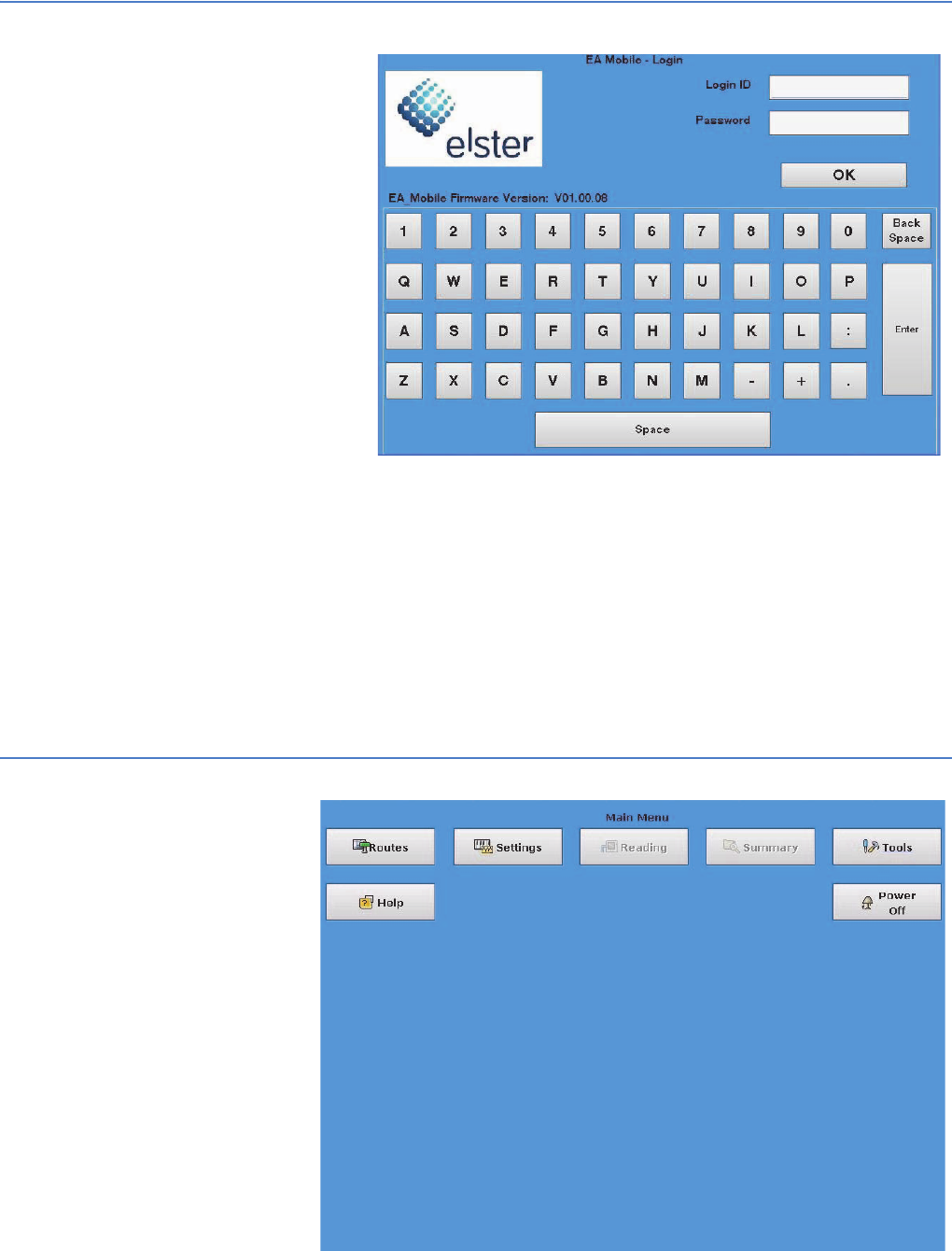
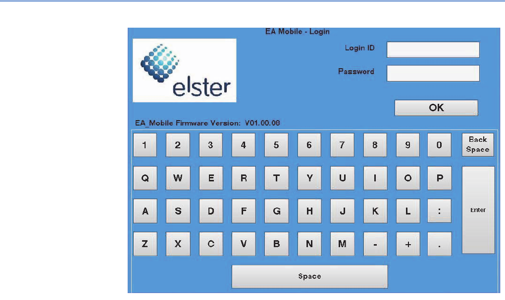
Figure 3-2.
5. Enter the user name and the password and then press the OK button.
Note: The initial user name is ‘ELSTER’ and the initial password is
‘357837’. For security purposes, this user account may be
removed after new user accounts are created and logged in.
Note: Make sure to enter the user name in all capital letters.
If the log in is successful, the system displays the Main Menu as shown
below.
Figure 3-3.

EA Mobile User Guide
3. Quick Start Guide
27
Note: The Reading and Summary buttons will be disabled (that is,
grayed out and unselectable) until a route is loaded.
Loading a new route
To load a new route:
1. From the Main Menu, press the Routes button.
The Routes menu is displayed with the following buttons: Load New Route,
Save Current Route, Resume Route, Save Old Route, and Close, as shown
below.
Note: The Save Current Route button will be disabled until a route is
loaded.
Figure 3-4.
2. Press the Load New Route button.
The File Manager window is displayed as shown below with a usb0
subfolder.
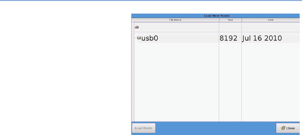
EA Mobile User Guide
3. Quick Start Guide
28
Figure 3-5.
3. Click on the usb0 subfolder.
The File Manager window displays the subfolders for folder usb0 including
the subfolder named TraceVRT.
4. Click on the TraceVRT subfolder.
The subfolders for the different routes will be displayed in the File Manager
window.
5. Select on the route that you wish to load.
A file named Reading.rte is displayed as a part of the selected folder.
6. Click on the Reading.rte file and then click on the Load Route button located
in the bottom left corner of the screen.
A bar graph window should open and be updating to indicate the progress
of the loading route.
Once the route is completely loaded without errors the Okay button in
bottom right corner of the bar graph window becomes enabled and the bar
shows 100.
7. Press the Okay button.
8. Press the Close button in the bottom right corner and go back to the Load
New Route menu.
9. Press the Close button in the bottom right corner again and go back to the
Main Menu.
Note: Please verify the date and time before reading a route (see
“Setting Date and Time” on page 53).
Reading endpoints
Caution: Verify date and time before reading the route. The EA_Mobile
will set the endpoint date and time as it reads the route.

EA Mobile User Guide
3. Quick Start Guide
29
To start reading endpoints:
1. From the Main Menu, press the Reading button.
The EA_Mobile will open a new window and automatically start reading the
route loaded. The EA_Mobile starts in the mode specified in the guide file
(unless the GPS is not present, then the mode is forced to FIFO, see Figure
3-7).
At this point the EA_Mobile will begin to transmit, at minimum, keep-awake
signals to endpoints within range. If there are endpoints remaining on the
route to be interrogated, and they are in the window, the EA_Mobile will
automatically begin interrogation.
2. Verify that the EA_Mobile indicator conditions are as shown in Figure 3-7.
Note: The EA_Mobile includes a TX / POWER MGR panel. The TX /
POWER MGR panel includes a Charge indicator.
Figure 3-6. TX / POWER MGR panel
EA Mobile User Guide
3. Quick Start Guide
30
Figure 3-7. EnergyAxis panel
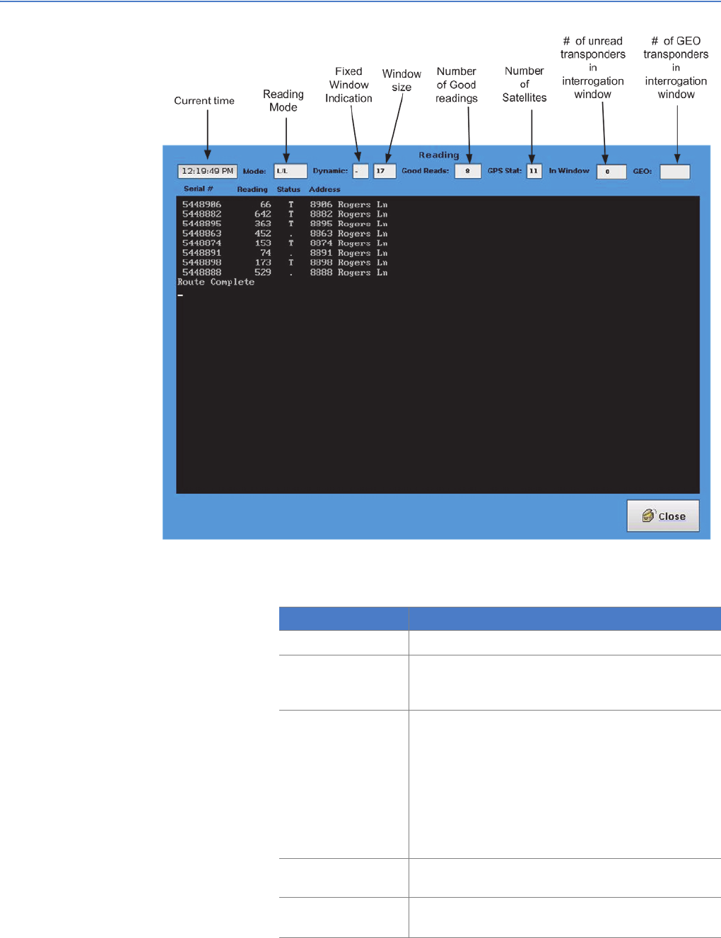
Figure 3-8 shows an example of a Reading mode header.
[8] ACTIVITY
#Indicator Label Function Start-up Condition
1[Alarm] SILENCE button [Not an indicator but a push button] --
2CHARGE Battery Charging Status (Power AMP / Mgr.) ON (green or red)
3TEMP Temperature status ON (green)
4BATT Battery status ON (green)
5LINE +12V line status ON (green)
6POWER [Next to BATT light] Power status ON (red)
7ENABLED TX enabled ON (green)
8ACTIVITY Shows transceiver activity OFF (green)
EA Mobile User Guide
3. Quick Start Guide
31
Figure 3-8.
The table below describes the information listed on the Reading mode
display:
Item Description
12:19:49 PM Shows current time from the EA_Mobile internal clock.
Mode Indicates the Reading mode currently selected. In this
case it is L/L representing Lat/Lon mode. Other modes
are FIFO and GEO.
Dynamic • Fixed Window Size Flag - The ‘–’ indicates the window
is a fixed size.
• Window Size:
• Indicates in the forward direction the interrogation
window size if 17 × 100 feet or 1700 feet.
• To the side of the vehicle the distance is half or 850
feet.
Note: The interrogation window is approximately an
oval.
Good Reads Indicates the total number of good reads. In this example,
8 endpoints have been successfully interrogated.
GPS Stat Indicates the GPS status. In this example, GPS is active
and is currently receiving data from 11 satellites.

EA Mobile User Guide
3. Quick Start Guide
32
The table below describes the GPS Status Codes and their meaning:
3. You may now begin driving the route.
The EA_Mobile will automatically scan for endpoints within its interrogation
window. You will hear a beep each time the EA_Mobile gets a good
response from a endpoint (unless the “Beep on Good Read” option is turned
off).
In Window Indicates the number of endpoints currently in the
interrogation window. In this example, there are 0
endpoints.
GEO Indicates the number of GEO endpoints in the
interrogation window. In this example, there is no GEO
indicated since the EA_Mobile is not in GEO mode.
Value Description
XX (A numerical value will be displayed)
The GPS receiver is communicating with the EA_Mobile
and is producing valid position data. The value shows the
number of satellites.
- The GPS receiver is not properly communicating with the
EA_Mobile or is not connected.
A The GPS receiver is properly communicating with the
EA_Mobile; however, the GPS is not getting good data
from the satellites or the EA_Mobile is in FIFO mode.
Item Description
EA Mobile User Guide
3. Quick Start Guide
33
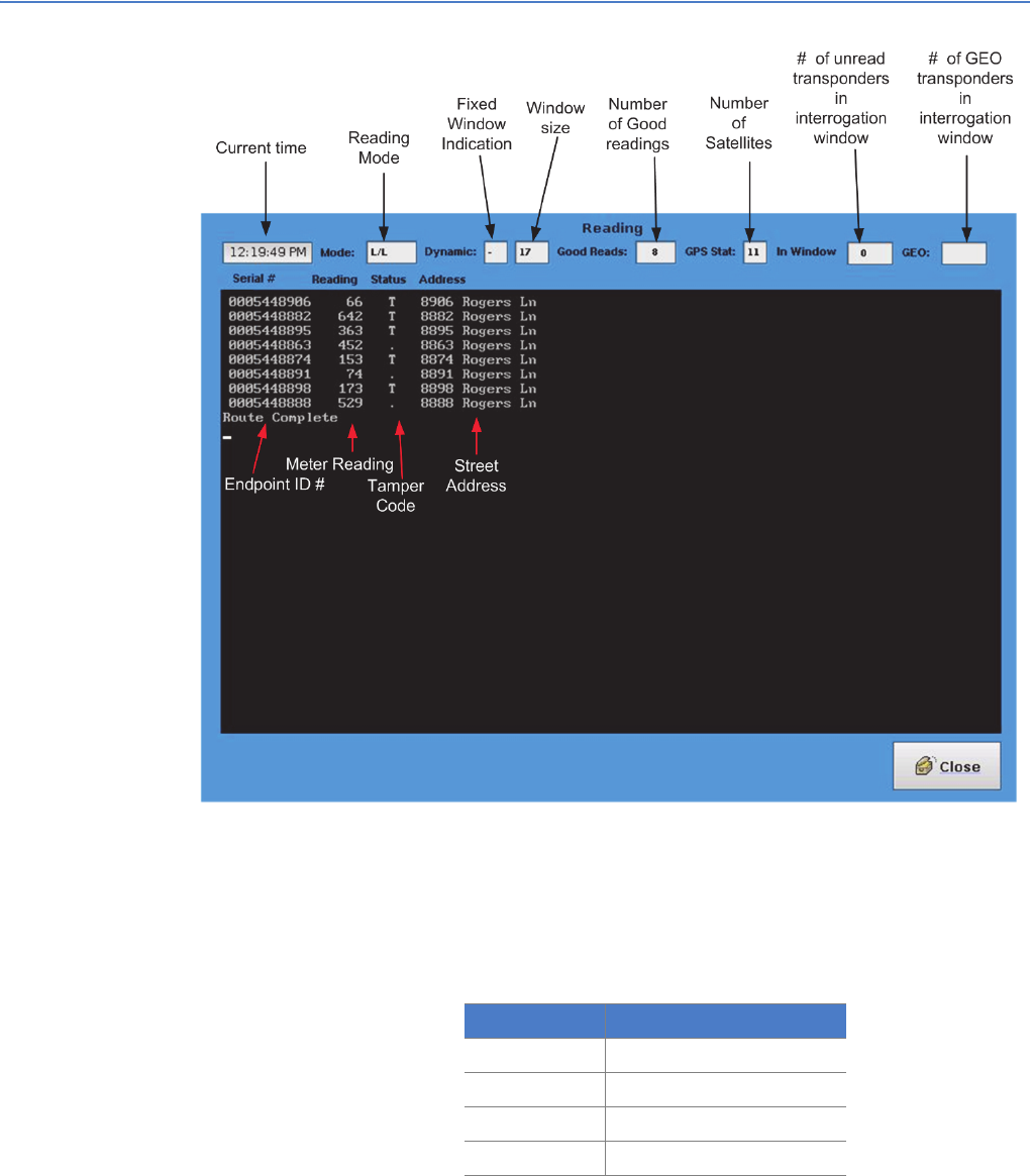
Figure 3-9.
Upon receiving endpoint data, the EA_Mobile will display whatever data it
has acquired regarding that particular interrogation attempt including:
• Endpoint serial number
•Meter reading
• Tamper status:
• Street address
If a endpoint replies with tamper code T indicating potential evidence of
tampering, the EA_Mobile will automatically attempt to reset the tamper
indicator. (You may turn off this option off on the Tools menu.
Status Code Meaning
• [bullet] Non-tampered
T Tampered
R Tamper reset successful
F Tamper reset failed

EA Mobile User Guide
3. Quick Start Guide
34
Pausing or ending a reading session
1. To pause or end a session or route, press the Close button on the bottom
corner of the screen.
Note: The EA_Mobile automatically saves the last 30 routes on the
systems drive. (When 30 routes have been saved, the
EA_Mobile will overwrite the oldest route.
— OR —
To save the current route, press the Close button on the bottom of the
screen.
This takes you to the Main Menu.
2. Press the Routes button and then click the Save Current Route button.
This saves the results of the current route to the USB flash drive. (This is the
button you would likely select when a route is completed and you are ready
to load a new route or when you are done.)
— OR —
To exit the system, go to the Main Menu and press the Power Off button.
Note: Powering down the system will not result in data being lost,
even if the route is not saved to the USB flash drive.
Resuming a route
1. From the Main Menu, press the Routes button.
A new menu is displayed with the following buttons: Load New Route, Save
Current Route, Resume Route, Save Old Route, and Close as shown in
Figure 3-10.
Note: If a route has not been previously loaded, the Save Current
Route button will be disabled.
Figure 3-10.
EA Mobile User Guide
3. Quick Start Guide
35
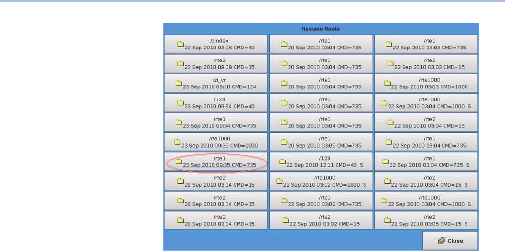
2. Press the Resume Route button once.
A window displays listing the last 30 routes read by the EA_Mobile.
Figure 3-11.
3. Select the desired route by finding the route with the time stamp close to the
time you loaded the route and with your route’s directory name.
The last file loaded is the highlighted route with a route name of /rte1 loaded
on 23 Sep 2010 9:35 with 735 commands.
Note: If an S follows the command data, the route has been saved.

4CONTROLS AND
INDICATORS
The EA_Mobile hardware offers a variety of audible and visual indicators and
interaction mechanisms to tell you how the EA_Mobile is functioning internally
and give you control over certain functions.
This chapter describes these controls and indicators along with their conditions
and any actions you may need to take in response.
The LCD Touch screen display can also provide system indications and controls.
These capabilities are discussed in Chapter 5, “Operating the EA_Mobile.”
Controls and indicators Figure 4-1 and Figure 4-2 show the indicators and controls located on the
EA_Mobile’s front panel. Some of the indicators will change color or appearance
when the EA_Mobile is actively acquiring endpoint data.
Transmit and power manager controls and indicators
Transmit and power manager controls and indicators are located on the center
front panel of the EA_Mobile. The EA_Mobile indicator lights (LEDs) and alarms
convey information regarding the status of the power supply unit, internal
temperature and transmitter/receiver operation. The controls allow you to turn on
power and silence alarms.
Note: The EA_Mobile includes a TX / POWER MGR panel. The TX /
POWER MGR panel includes a Charge indicator. See Table 4-1
for the configuration of your EA_Mobile.
EA Mobile User Guide
EA Mobile User Guide
4. Controls and indicators
37
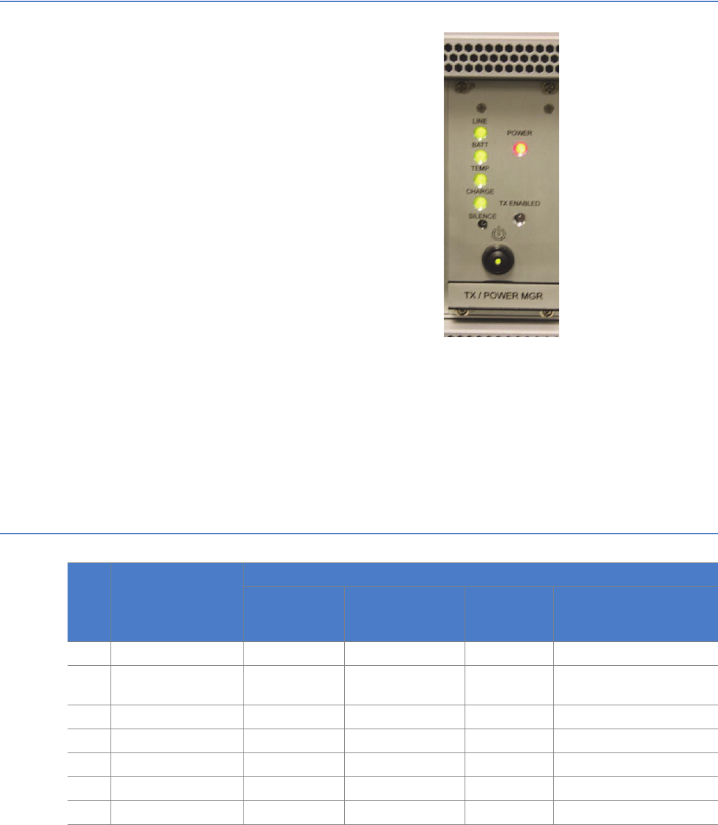
Figure 4-1. TX / POWER MGR panel
Main POWER switch
The main Power switch turns on or turns off the 12 Volt power to the EA_Mobile. It
is a rocker switch labeled to show the ON and OFF positions.
Note: Key numbers shown in brackets [ ] in Figure 4-2 refer to the Key
numbers in the table.
Familiarize yourself with the normal conditions of these indicators at startup and
during interrogation so that any improper conditions will quickly alert you to take
action.
Caution: Failure to respond to certain improper indications in a timely
manner may lead to poor EA_Mobile performance and, in
some cases, permanent equipment damage.
Table 4-1. TX / Power Mgr. Indicators
Key Indicator Condition
Optimal t
EA_Mobile
startup
During interrogation Warning
conditions
Error condition
1[Alarm] SILENCE button
2CHARGE Green Green (when
charging)
NA Red (when discharging)
3TEMP Green Green Yellow Red
4BATT Green Green Yellow Red
5LINE (+12V) Green Green Yellow Red
6POWER Red Red NA Off
7ENABLED Off Green NA Off when interrogating
EA Mobile User Guide
4. Controls and indicators
38
Note: As a rule of thumb, all indicator lights except the transmit
ENABLED light - should be ON continuously while the EA_Mobile
is operating. If the remaining lights are off or flickering, you may
need to troubleshoot an error condition. See Appendix A,
“Troubleshooting the EA_Mobile” for details.
[Alarm] SILENCE button
Any new alarm condition (also shown by indicator lights) will activate the audible
alarm.
• If you choose to ignore the problem, you may press the Silence button to
silence the alarm.
Even after you silence the alarm, however, the indicator light will continue to
flash until the actual alarm condition ceases. If the alarm condition persists
or recurs, the audible alarm will sound again.
CHARGE
[Green] Indicates the battery is charging. [Red] Indicates the battery is
discharging.
TEMP
[Green] Indicates the internal temperature of the EA_Mobile is below 130° F. It
should be ON continuously whenever the EA_Mobile is powered.
If this light is flashing or is Red, it indicates the internal temperature has exceeded
the threshold:
• Check the cooling fan. Remove any clogs and reposition the EA_Mobile if
necessary to ensure adequate air circulation to the cooling fan.
• If the fan is operating properly, lower the ambient temperature in the vehicle
either by opening windows or by adjusting the heater or air conditioning
thermostat.
• If the fan is not operating, call Elster’s Service Department.
Warning: If the EA_Mobile overheating conditions cannot be corrected
immediately, shut down the EA_Mobile. Failure to do so may
result in damage to EA_Mobile components.
BATT
[Green] Indicates the internal battery voltage is stable and adequate to power the
EA_Mobile. It should be ON continuously whenever the EA_Mobile is powered.
• If this light is flashing, it indicates the EA_Mobile is running on battery power.
The internal battery is for temporary emergency use only.
Warning: If the BATT light is flashing or is Red, it may indicate the internal
battery has dropped to an unusable voltage. Immediately shut
down the EA_Mobile!
LINE
[Green] Indicates the 12 Volt supply from the vehicle’s accessory/cigarette lighter
receptacle is delivering adequate voltage to power the EA_Mobile. The LED
should be ON continuously whenever the EA_Mobile is powered.
If this light is flashing or is Red, it indicates the 12 Volt supply has dropped to an
unusable voltage:

EA Mobile User Guide
4. Controls and indicators
39
• Verify the power cable is connected.
• Check for vehicle accessories (radio, tape player, CD, etc.) that can be turned
off to minimize the power drain.
• If the LINE light continues to blink, verify the accessory/cigarette lighter fuse is
intact.
• If the fuse for the accessory/cigarette lighter has blown, shut down the
EA_Mobile and replace the fuse.
• If the LINE light continues to blink, the vehicle’s alternator may be unable to
produce adequate operating current and should be serviced.
POWER
[Red] Indicates the +12 Volt power supply to the amplifier is on. It should be ON
whenever the EA_Mobile is powered.
• If it is not ON, check the fuse and replace if necessary. See “Checking a
fuse” on page 41 for details.
• If the fuse is OK, contact Elster’s Service Department.
ENABLED
[Green] Indicates the EA_Mobile transmitter is actively transmitting. The LED
should be ON during interrogation or once turned on using the Tools window.
• If this light is not ON during interrogation or when transmitter is turned on
from the Tools window, contact Elster’s Service Department.
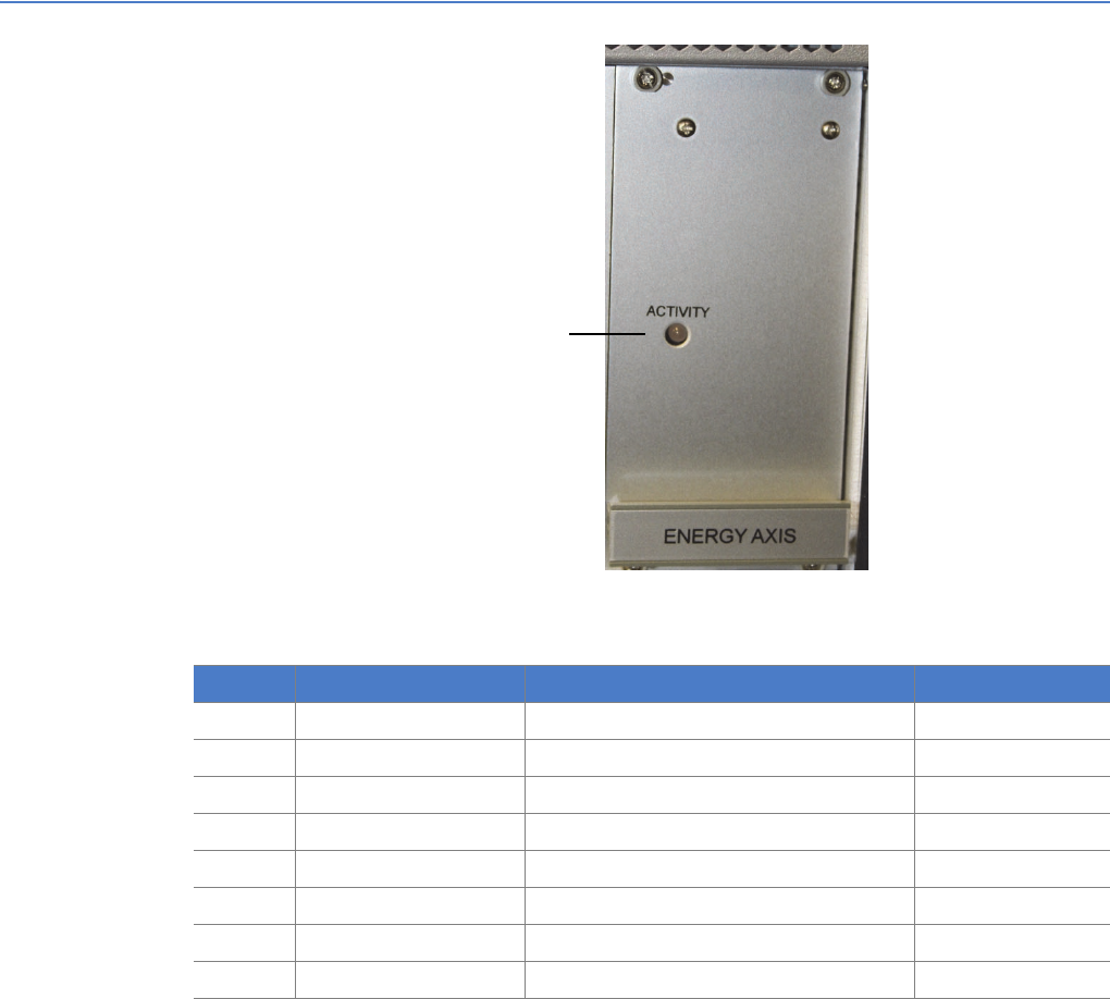
EnergyAxis panel indicator
The EnergyAxis panel is located on the right side of the EA_Mobile front panel
(Figure 4-2). The sole indicator is ACTIVITY. This light indicates if serial
communications are occurring. This light generally appears as a blinking red or
orange. This indicates activity is occurring over the serial communications port.
Figure 4-2. EnergyAxis panel
[8] ACTIVITY
EA Mobile User Guide
4. Controls and indicators
40
Note: Key numbers shown in brackets [ ] in Figure 4-2 refer to the Key
numbers in Table 4-2.
ACTIVITY
The activity light indicates if there is activity on the EnergyAxis transceiver antenna.
• It will blink Red whenever RS-232 data is received.
• It will flicker Green whenever RS-232 data is read from the transceiver.
• If the transceiver is both receiving and reading, the Activity indicator will
appear as Amber.
This includes communication with the transponder and the CPU.
This indicator should flicker whenever the EA_Mobile is in reading mode. It’s
flickering becomes more solid when transmitting and receiving data from
transponders.
Fuses
The EA_Mobile contains two internal fuses accessed from the back panel (Figure
4-3)FusesFuses. These are standard automotive-type fuses:
Figure 4-3. Fuses
Table 4-2. Receiver (REC) and Transmitter (XMIT) Indicators
Key Indicator Color Condition
At EA_Mobile
startup
When EA_Mobile
is powered
During
interrogation
Error condition
8ACTIVITY Red OFF OFF Blinking (Red or
Green)
OFF
Input 20 Amp AGC 32V
Battery 20 Amp AGC 32V
Input
fuse
Battery
fuse

EA Mobile User Guide
4. Controls and indicators
41
Removing a fuse
To check a fuse you must remove it:
1. To remove the selected fuse, insert a flat-head screwdriver (or a dime) into
the slotted center of the fuse holder.
2. Turn counterclockwise until the fuse holder springs out.
3. Pull the fuse holder and fuse out of the EA_Mobile back panel.
Checking a fuse
To check the fuse:
1. If the fuse has a window in it, check the metal filament inside.
• If it is clearly broken, the fuse is blown.
• If the filament appears to be intact, it could still be broken at one end
where the break is less apparent. You may want to try replacing the fuse
with a known good fuse, just to be sure.
• If the fuse has no window, replace with a known good fuse to see if this
solves the problem.
Replacing a fuse
1. To replace the fuse, remove the old one from the fuse holder and insert a
new one.
• Verify the fuse has the proper amperage and voltage characteristics.
2. Replace the fuse holder (with new fuse) in the socket on the EA_Mobile back
panel.
3. Insert the screwdriver/coin into the center slot on the fuse holder cap, push
in and turn clockwise until tight.
Specifications The following table shows the EA_Mobile specifications:
Power Source Standard 13.8 VDC vehicle power, sealed internal gel-cell battery
Power Consumption 100 Watts (8 Amps maximum current) fully loaded
RF Transmitter Power is 12.5 Watts nominal. Frequency is software tunable to licensed
frequency
Transceiver ISM Band, Frequency Hopping 900 MHz transmit and receive
GPS Receiver Accuracy, approximately 3 meters
FCC Compliance Part 90, including Parts 90.210(d) FCC ID: G8JEAMOBILE1
Operating Temperature
(Ambient)
-10C to 50C (14F to 122F)
Storage Temperature -10 °C to +40 °C (+14 °F to +104 °F)
Size 17”W x 7”H x 12”D
Weight (approximate) 33 lbs (15 kg) in operational configuration
62 lbs (28 kg) in carrying case
Fuses Input 20 Amp AGC 32V
Battery 20 Amp AGC 32V

5OPERATING THE
EA_MOBILE
This chapter describes the functions and operations of the EA_Mobile and
provides certain background information regarding technologies involved, where
appropriate.
Accessing EA_Mobile
functions
After the components have been assembled and connected and the EA_Mobile
has been properly installed in the vehicle (see Chapter 2, “Preparation and
installation”), you are ready to begin the process of automated meter reading.
Note: If you are using the EA_VID, there is no need to load the route
on the EA_VID. The EA_Mobile will copy the data to the EA_VID
over the Ethernet cable. If the Ethernet cable becomes loose or
is removed, it takes the EA_Mobile and EA_VID several seconds
to re-establish communications. These communications are
used to copy a route to the EA_VID, to display the EA_Mobile
window on the EA_VID and to send data bi-directionally
between the EA_Mobile and the EA_VID.
Use the following steps to access EA_Mobile functions:
1. Obtain a USB flash drive that has been loaded with a route by Route
Manager software for use in the EA_Mobile.
The routes on the USB flash drive must include the following three files for all
route directories:
•start
•guide
• Reading.rte
2. Insert the USB flash drive into the slot labeled USB 2 on the EA_Mobile front
panel.
3. Turn on the EA_Mobile’s Main POWER switch located on the front panel to
the right of the USB drive (Figure 5-1) and allow a couple of minutes for the
system to boot up.
Once the system is ready, the touch screen monitor will display the log in
screen.
EA Mobile User Guide
EA Mobile User Guide
5. Operating the EA_Mobile
43
Figure 5-1.
4. Log in to the EA_Mobile by entering your Login ID and Password.
The Main Menu displays.
5. To start reading, from the Main Menu, press the Reading button.
The EA_Mobile will start reading endpoints within range. The default
reading mode is determined by the guide file.
6. To return to Command mode, close the Reading window by pressing the
Close button.
All other buttons are Command mode options. See Chapter 7, “Command
mode” for details.
EA_Mobile modes and
menu options
The EA_Mobile has two primary operational modes: Reading mode and
Command mode.
Command mode
Command mode allows you to view and analyze system data and parameters,
alter operational parameters, load, save and resume a route, and perform
various tasks. Command mode consists of six main menu buttons: Routes,
Settings, Summary, Tools, Help, and Power Off. See Chapter 7, “Command mode”
for details on using Command mode.
Reading mode
Reading mode allows you to read/interrogate endpoints. See Chapter 6,
“Reading mode” for details on using Reading mode.

EA Mobile User Guide
5. Operating the EA_Mobile
44
Modes and menus
The following table lists the EA_Mobile modes and the menu options that may be
selected from within those modes. The balance of this chapter details the use of
each mode and selection.
Command mode
See Chapter 7, “Command mode” for details on each command.
Menu Submenu 2nd level 3rd level Function
Routes
window
Load New
Route button
-- -- This button opens a file manager window and
allows the user to find and load a route from the
USB flash drive.
Save Current
Route button
-- -- This button is used to save the current route to the
USB flash drive.
Resume Route
button
-- -- This button is used to resume one of the last thirty
routes loaded.
Save Old
Route button
-- -- This button is used to save one of the last thirty
routes loaded.
Settings
window
System Setup
button
Read Method Lat/Lon Latitude/Longitude mode selects for interrogation
only those endpoints having Lat/Lon coordinates
that are within the interrogation window.
FIFO FIFO mode (first-in-first-out) considers all endpoints
on the route to be within the interrogation window
and will repeatedly search through the route list
looking for any unread endpoints that are within
range at that given moment.
GEO GEO mode selects any endpoints with valid Lat/
Lon coordinates that are within the interrogation
window AND all endpoints without Lat/Lon
coordinates, regardless of proximity.
Display Good
Reads
Yes Enables system to display good reads.
No Enables system to not display good reads.
Sound on
Good Reads
Yes Enables system to play sound on receiving good
reads.
No Enables system to not play sound on receiving
good reads.
Reset Tampers Yes Enables system so it can reset tampers.
No Disables system from resetting tampers.
Window Size 0-17 Sets interrogation window size.
Sort Unread
Display
Yes Enables system to sort unread endpoints
displayed.
No Disables system from sorting unread endpoints
displayed.

EA Mobile User Guide
5. Operating the EA_Mobile
45
Settings
window
System Setup
button
Monitor
Unread
Display
Yes Enables system to monitor unread display.
No Disables system from monitoring unread display.
Set Perm
button
Unit Serial # -- Displays Unit’s serial number.
Last Updated: -- Displays the date of last update.
Encryption Key -- Encryption key used in determining the password
needed.
User Accounts
button
First Name -- First name of displayed User Account.
Last Name -- Last name of displayed User Account.
Login ID -- Login ID for displayed User Account.
Password -- Hidden password for displayed User Account
Record -- Shows which user account of total User Accounts
is displayed.
First -- Goes to the first User Acount is the list
Previous -- Goes to the previous User Account
Next -- Goes to the next User Account.
Last -- Goes to the Last User Account.
New -- Creates a new user at the next available User
Account, there is a maxium of 25 Users. After
selecting new a new user account can be entered
using the touch screen and the keypad on this
window.
Delete -- Deletes the present User Account.
Save -- Saves the new or modified User Account
Date and Time System Time -- Displays and allows modification of system’s
current time.
System Date -- Displays and allows modification of system’s
current date.
Summary
window
All button -- -- Show all endpoints in the route.
UnRead
button
-- -- Shows endpoints who have not yet completed
reading or who failed to read.
Un-int button -- -- Show only endpoints that have not been
interrogated.
Good button -- -- Show all endpoints that have responded
successfully to interrogation, including tampered
units.
Tamp. button -- -- Show all endpoints that have returned a tamper
status including those in reset or reset failed
condition.
M. Geo -- -- Not yet implemented.
In WInd -- -- Shows all endpoints within the interrogation
window, that is, reading is not yet completed.
Menu Submenu 2nd level 3rd level Function

EA Mobile User Guide
5. Operating the EA_Mobile
46
Reading mode
See Chapter 6, “Reading mode” for details on using Reading mode.
Tools window Troubleshoot -- -- Opens a window which allows the user to
troubleshoot issues with endpoints.
Route Scan -- -- Not yet implemented.
Sync EA_VID -- -- This button is used to re-synchronize with the
EA_VID.
Help window About button -- -- Display results including software version
information.
Guide button -- -- Brief online command summary.
Power Off
button
-- -- -- Powers the system down. The user will be
prompted to confirm power down and if a route is
loaded, but not saved, a message will warn the
user the route was not saved.
Menu Submenu 2nd level 3rd level Function

6READING MODE
Note: Please verify the date and time before reading a route (see
“Setting Date and Time” on page 53).
“EA_Mobile modes and menu options” on page 43 listed the various Reading
mode and Command mode buttons. Reading mode has three interrogation
control options:
•Lat/Lon option
•FIFO option
•GEO option
Reading mode can be entered from the Main Menu by pressing the Reading
button after a route is loaded. See “Loading a new route” on page 27 for details
on loading a route.
Caution: Verify date and time before reading the route. The EA_Mobile
will set the endpoint date and time as it reads the route.
The following figure shows the Reading window.
EA Mobile User Guide
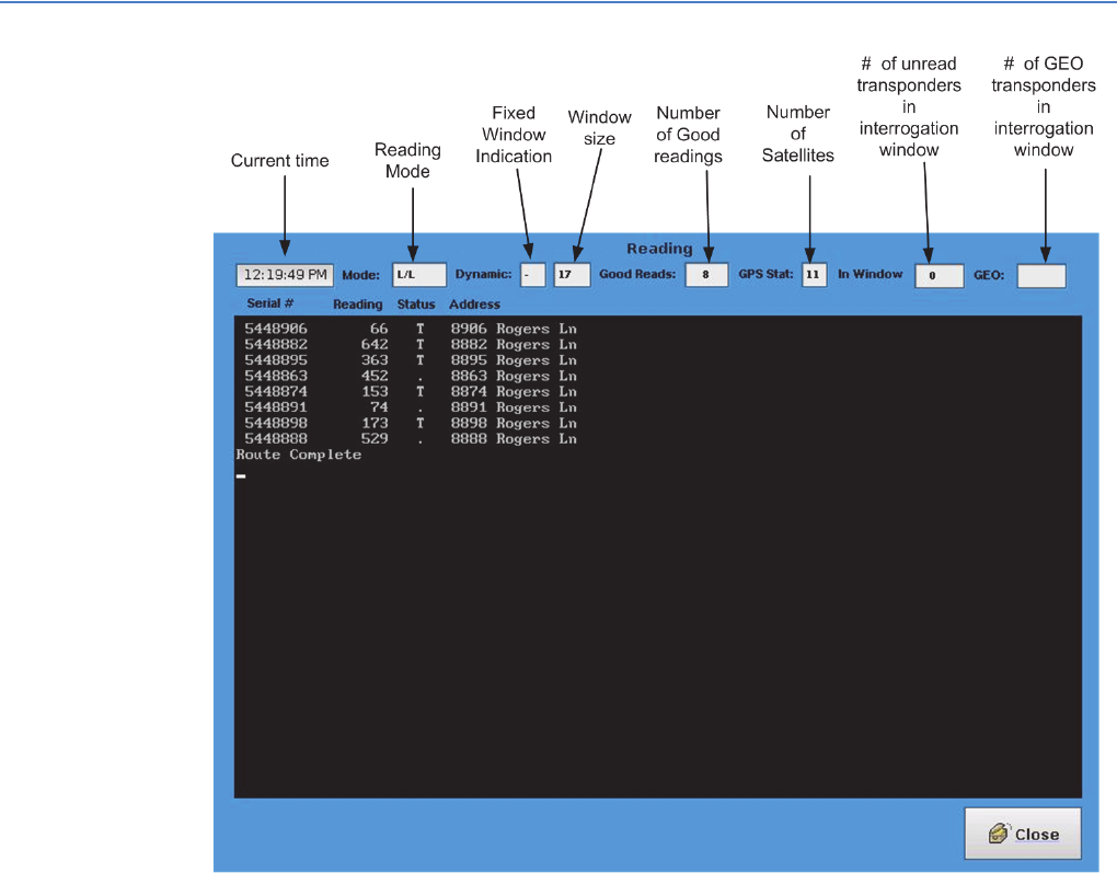
EA Mobile User Guide
6. Reading mode
48
Figure 6-1.
The three Reading mode options allow you to determine the method by which
endpoints will be selected for interrogation:
•Lat/Lon option uses latitude and longitude coordinates of the meter’s
endpoint (along with current coordinates of the EA_Mobile/vehicle) to
determine which endpoints in the route should be within the interrogation
window at any given time. It then scans only those endpoints.
Note: If no satellites are detected, the EA_Mobile will automatically
switch to FIFO mode.
•GEO option selects any endpoints with valid Lat/Lon coordinates that are
within the interrogation window AND all endpoints without Lat/Lon
coordinates, regardless of proximity to the EA_Mobile.
Note: If no satellites are detected, the EA_Mobile will automatically
switch to FIFO mode.
•FIFO option (first-in-first-out) considers all endpoints on the route to be within
the interrogation window and will repeatedly search through the route list
looking for any unread endpoints.
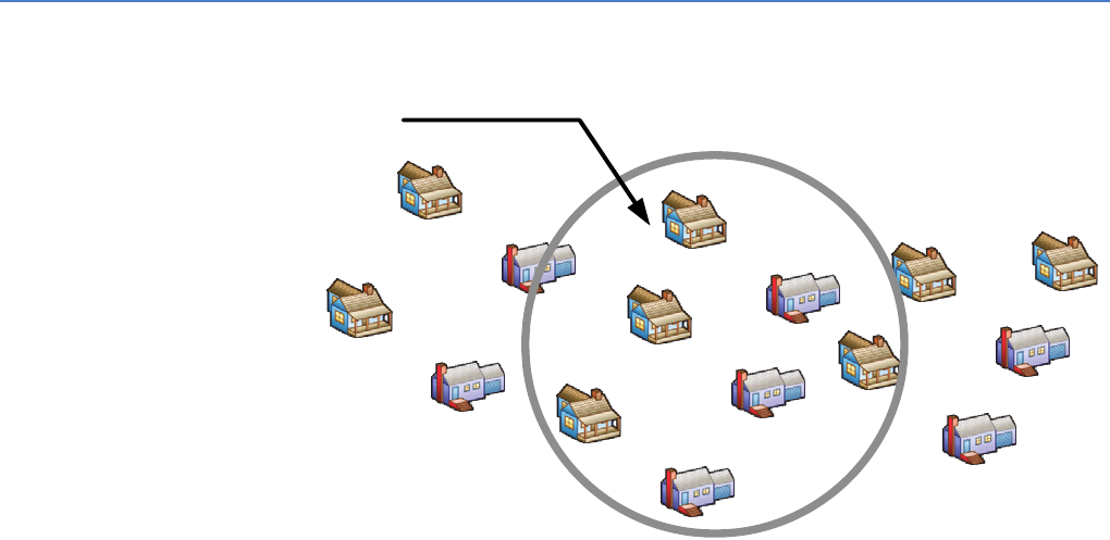
EA Mobile User Guide
6. Reading mode
49
Discontinuing reading
To discontinue reading when in the Reading window, press the Close button.
Change Reading mode options
To select/change Reading mode options, see “System Setup button” on page 68
Audible signal
The EA_Mobile default is to emit an audible beep upon each good read. See
“System Setup button” on page 68 for details on changing this setting.
Route Sequence
You may drive the route in any order since the EA_Mobile is constantly computing
which endpoints are available for interrogation.
Lat/Lon option Lat/Lon (Latitude/Longitude) is the default Reading mode (unless changed in the
Guide file via Route Manager software). It allows you to automatically select for
interrogation only those endpoints determined to be in the interrogation window
of the EA_Mobile at any given time. This means that only a portion of the route list
must be scanned at a location allowing for maximum speed in capturing route
data.
• Lat/Lon is recommended for routes of 300 endpoints or more.
• Endpoints with zero or default coordinates will not appear for interrogation
in this mode.
• Use the Lat/Long option when all or most endpoints on your route have valid
Lat/Lon coordinates and your GPS system is functioning normally.
Figure 6-2.
L/L
L/L L/L
L/L
L/L
L/L
L/L
L/L
Lat/Lon option selects
only those transponders
with L/L coordinates that
are calculated to be
within range of the RTMI
interrogation window at
the given moment.
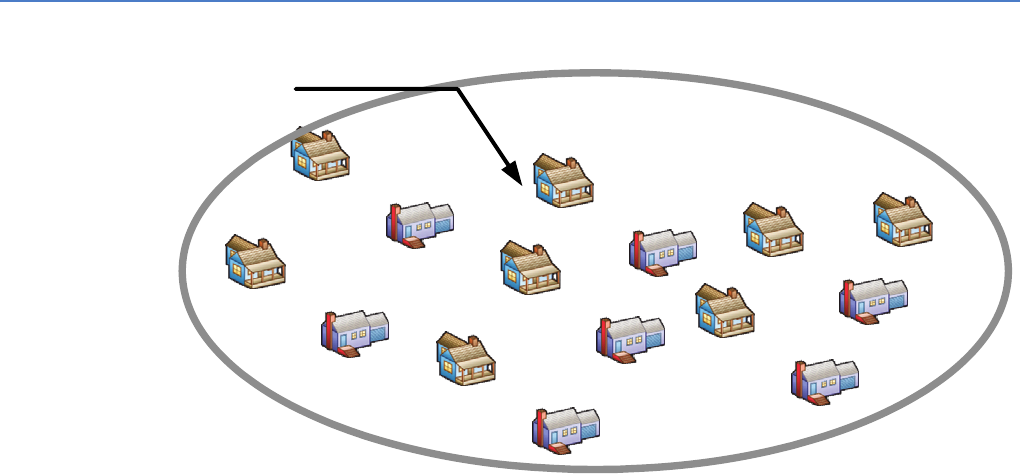
EA Mobile User Guide
6. Reading mode
50
Establishing Lat/Lon coordinates
For new routes whose endpoints have not yet been assigned coordinates, the
FIFO Mode is recommended. Once a endpoint is located and responds, the GPS
can then provide latitude and longitude information to be stored along with other
account information. For routes having many endpoints both with and without
coordinates, the GEO mode is recommended, as it streamlines the search for
endpoints that have coordinates while allowing for unassigned endpoints to be
interrogated and their coordinates assigned. Interpolated Lat/Lon (captured by
the EA_Mobile) are the coordinates of the EA_Mobile when the interrogation is
validated, however, these coordinates may be up to 1500 ft away from the actual
endpoint position. Therefore, for optimal performance hard coded Lat/Lon
coordinates taken at the endpoint are recommended.
Using Lat/Long coordinates
The GPS receiver provides latitude and longitude coordinates for the EA_Mobile-
equipped vehicle. Based on this position, the EA_Mobile can calculate which
endpoints should be in the interrogation window of the system. It then sends out
interrogation signals looking for only those endpoints. When all endpoints in the
interrogation window (IW) have been read, you can continue on the route.
FIFO option In the FIFO option, the system considers all endpoints to be within the
interrogation window at all times. The FIFO method does not require Lat/Lon
coordinates for either the endpoints or the EA_Mobile/vehicle. Instead it simply
reads through the route list over and over as you drive the route, scanning for all
unread endpoints on the list.
• This is the slowest Reading option, especially at the beginning of a session.
As endpoints report their data, the list becomes shorter and thus the search
for unread endpoints proceeds more and more quickly.
Figure 6-3.
Use the FIFO option for the following situations:
L/L
L/L L/L
L/L
L/L
L/L
L/L
L/L
FIFO option continuously
selects for interrogation
ALL unread transponders
in the route, regardless of
coordinates or location.
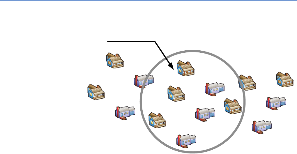
EA Mobile User Guide
6. Reading mode
51
• none of the endpoints in the route have been assigned coordinates
• when the GPS system is not delivering usable location data
• when you have a very small route list (the FIFO option requires less than 300
endpoints) and the EA_Mobile/vehicle is moving slowly or stopped.
Assigning endpoint coordinates
For a route whose endpoints have not yet been assigned formal latitude and
longitude coordinates, the system can find and interrogate each endpoint using
the sequential FIFO method. It then automatically assigns temporary GPS
coordinates (according to EA_Mobile/vehicle position) as the endpoint is read.
Each time the endpoint is read thereafter, its coordinates will be rewritten in the
same manner until formal coordinates are entered in the route for that endpoint
via host software.
GEO option For endpoints with Lat/Lon coordinates, the GEO option seeks only those that are
determined to be within the interrogation window (as in the Lat/Lon option). It also
seeks ALL endpoints without coordinates at all times during the route until they
are successfully read, regardless of the EA_Mobile’s present location. Routes with
more than 100 endpoints without Lat/Lon coordinates are not allowed in the GEO
option.
Figure 6-4.
Assigning coordinates
When a endpoint is located and read, the EA_Mobile assigns temporary
coordinates based on the current EA_Mobile/vehicle position.
• Use the GEO option when you want to streamline coverage and optimize
data acquisition speed for a route that contains a mix of endpoints with and
without Lat/Lon coordinates.
L/L
L/L L/L
L/L
L/L
L/L
L/L
L/L
GEO option selects those
transponders with L/L
coordinated that are
calculated to be within
range of the RTMI at the
given moment –
plus ALL transponders
with L/L coordinates,
regardless of location.

EA Mobile User Guide
6. Reading mode
52
In the GEO option, the status line is the same as in Lat/Lon or FIFO mode, except
the GEO mode status shows the total GEO mode endpoints in the route.
Figure 6-5.
For the route above, there are 12 GEO endpoints and 53 In window” L/L
endpoints.
Reading meters The following describes the steps involved in reading endpoint-equipped meters
automatically using the EA_Mobile.
Loading the route
To load the route:
1. From the Main Menu, select the Route button.
2. From the Route window, select the Load New Route button.
3. Using the File Manager window find and select the Reading.rte file to be
loaded.
4. Press the Load Route button and wait for the load to complete.
5. Press the Okay button.
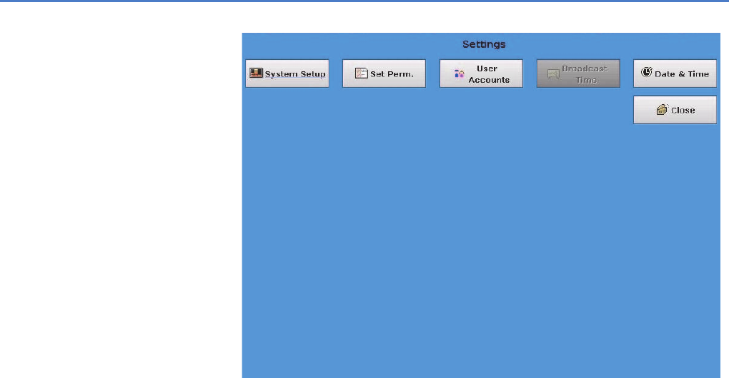
EA Mobile User Guide
6. Reading mode
53
Set the Reading mode
The Reading mode (L/L, FIFO or GEO) can be changed if required:
1. Return to the Main Menu by pressing the Close button on the File Manager
window and then the Route window.
2. From the Main Menu, select the Settings button.
3. From the Settings window, select the System Setup button.
4. In the System Setup menu, press the button of the mode you want.
You can also set other system settings if desired at this time, such as turning
on/off audible beep. See Chapter 7, “Command mode.”
5. Press the Close button to return to the Settings window.
6. Press the Close button to return to the Main Menu.
Setting Date and Time
Caution: Failure to perform this procedure prior to reading a route may
result in the endpoints having the incorrect date or time.
Before reading any endpoints, please verify that the date and time are set
correctly in the system using the following steps:
1. From the Main Menu, press the Settings button.
The Settings window displays.
Figure 6-6.
2. From the Settings menu, press the Date & Time button.
The Date & Time window displays.
EA Mobile User Guide
6. Reading mode
54
Figure 6-7.
3. If you need to adjust the date or time, use the + and - buttons next to the
Hour, Minutes, Seconds, Month, Day and Year to set the date and time.
4. Press the Close button to return to the Settings window.
5. Press the Close button to return to the Main Menu.
Entering Reading mode
Caution: Prior to reading a route, verify the date and time (see “Setting
Date and Time” on page 53).
To enter reading mode:
• Press the Reading button on the Main Menu.
The EA_Mobile will now start reading endpoints within range.
Driving the route
You may now drive the route in any order:
• The EA_Mobile will continuously determine which endpoints are available
for interrogation and will automatically interrogate.
• As the EA_Mobile receives a valid endpoint response it will add a new line
to the data display.
• The LCD touch screen monitor displays the results of the current
interrogations in text form and provides an audible beep upon each good
read (unless default audible signal settings have been changed) or the
volume is turned off on the LCD touch screen display.
EA Mobile User Guide
6. Reading mode
55
Entering Command mode
To access the Command mode at any time during a reading session:
• Press the Close button on the Reading Current Route window to suspend
reads until you return.
Resuming reading
Caution: Prior to resuming reading a route, verify the date and time (see
“Setting Date and Time” on page 53).
To resume reading where you left off:
• Navigate to the Reading window.
The EA_Mobile will now start reading endpoints within range.
Saving a route
To save a route:
1. Navigate back to the Main Menu and select the Route button.
2. Select the Save Current Route button on the Route window and wait while
the route is saved.
Note: If the Route was resumed, the route will be saved at the top
level directory of the USB. If the route to be saved was loaded,
and not resumed, the route will be saved in the directory on the
USB flash drive from where the route was loaded.
Powering down the EA_Mobile
To power down the unit:
1. Navigate back to the Main Menu and select the Power Off button.
This will ask you to confirm the Power Off and, if the route was not saved, it
will display a message indicating route not saved.
2. Press the Okay button to power down.
— OR —
3. Press the Cancel button to continue.
Note: The EA_Mobile automatically saves route data for the last 30
routes.
Resuming a route after powering down
Caution: Prior to resuming reading a route, verify the date and time (see
“Setting Date and Time” on page 53).
To resume a route after powering down or loading a different route:
1. Navigate to the Main Menu.
2. Press the Route button.
3. Press the Resume Route button.
EA Mobile User Guide
6. Reading mode
56
4. Select the Route you wish to resume by route directory, path name and time
route was loaded and press that route’s button.
The route will load and you can continue reading this route.
Note: Your route could be any one of the possible thirty route buttons.
Reading displayed data Any time the EA_Mobile is in Reading mode, the LCD touch screen will display a
header/status line showing the current status of eight parameters:
• Current time
•Reading mode
• Fixed Window size flag and window size indicator
• Number of good readings
•GPS status
• Number of endpoints in the interrogation window
• GEO mode - number of GEO endpoints
Figure 6-8.

EA Mobile User Guide
6. Reading mode
57
If the Display Good Reads feedback option is turned on (the default setting unless
changed using the System Setup window described in Chapter 7, “Command
mode”) in the System Setup command, the LCD touch screen will also display a
number of details regarding endpoints that have returned valid data. The
information displayed includes:
• Endpoint serial number
•Meter reading
• Tamper code
• Meter/endpoint street address
Header/Status line
Reading window
The data displayed in the Reading window includes the following:
• Serial # - This is the LAN ID of the meter’s endpoint. It will be displayed when
the endpoint is read and again, if necessary, when a Tamper indication is
cleared.
• Reading - This shows the current usage, as computed by the meter’s
endpoint (including, in some cases, a correction factor).
• Status - Shows the current tamper condition of the endpoint:
12:19:49 PM Current Time – This shows current time from the EA_Mobile internal
real-time clock.
Mode: Reading Mode – This displays the currently selected Reading mode.
In this example the mode is L/L or Latitude/Longitude. Allowed
modes are:
• L/L or Latitude/Longitude
• FIFO (first-in-first-out)
•GEO
Dynamic: • Fixed Window Size Flag - The ‘–’ indicates the window is a fixed
size.
• Window Size:
• Indicates in the forward direction the interrogation window
size if 17 × 100 feet or 1700 feet.
• To the side of the vehicle the distance is half or 850 feet.
Note: The interrogation window is approximately an oval.
Good Reads: Number of Good Readings - Indicates total number of good reads,
regardless of tamper condition. In this example, 8 endpoints have
been successfully interrogated.
GPS Stats: GPS status – Shows the level at which the GPS system is
communicating and delivering valid position data to the EA_Mobile.
In this example, GPS is active and is currently receiving data from 11
satellites.
In Window Number of endpoints in interrogation window – Shows the total
number of endpoints considered to be in the interrogation window
according to the parameters of the selected Reading mode.
GEO: GEO Endpoints – In Geo mode, shows the total number of GEO
endpoints considered to be in the interrogation window, otherwise
blank. In this example, the mode is L/L and thus the field is blank.
EA Mobile User Guide
6. Reading mode
58
• • (bullet) indicates non-tampered
• T indicates Tampered; If Reset Tamper is on, the endpoint will be
instructed to clear the tamper indication. The T or R result should appear
within a few seconds.
• R indicates the Tamper reset successful; meter reading is not displayed
since it was displayed when the endpoint was initially read.
• F indicates the Tamper reset failed; possible cause is a tilted meter that
will not allow the liquid tamper switch inside the endpoint to level for a
reset. Endpoint damage may also cause reset failure.
• L indicates Leak Detection (for water endpoints only) - The L character is
displayed when a leak condition is detected using the leak detection
route sequence commands.
• Address - Shows the street address for a given gas or water endpoint/
meter.

7COMMAND MODE
“EA_Mobile modes and menu options” on page 43 listed the various Reading
mode and Command mode buttons. Command mode gives you access to
EA_Mobile data and user functions. Command mode provides access to the
following windows:
•Routes window
•Settings window
•Tools window
•Summary window
•Help window
•Power Off button
These are represented by the buttons on the Main Menu as shown below.
Reading mode button was discussed in Chapter 6, “Reading mode.”
Figure 7-1.
EA Mobile User Guide

EA Mobile User Guide
7. Command mode
60
The corresponding submenu selections for each main menu item are listed
below:
When a button is pressed on the Main Menu its window will be displayed on the
LCD touch screen.
Routes window The Routes window buttons are related to USB access: loading, saving, and
resuming a route. The Routes window offers four buttons and a Close button
shown in the figure below:
Figure 7-2.
Main Menu Submenu Main Menu Submenu
Routes Load New Route button
Save Current Route button
Resume Route button
Save Old Route button
Summary All button
UnRead button
Un-int button
Good button
Tamp. button
M. GEO button
In Wind button
Help About button
Guide button
Tools Tx On button
Sync VID button
Troubleshoot button
Route Scan button
Settings System Setup button
Set Perm button
User Accounts button
Date & Time button
Power Off Power Off button
EA Mobile User Guide
7. Command mode
61
Load New Route button
The Load New Route button opens a file manager window (Figure 7-3) which
allows the user to navigate to the USB flash drive and to load a route from this
drive. The USB flash drive top level directory will be listed as usb0 in the file
manager window.
Loading a route
To load a route:
1. From the Main Menu, press the Route button.
This will open the Route window.
2. From the Route window, press the Load New Route button.
The Load New Route window will open.
Figure 7-3.
3. Select the usb0 folder and it will expand.
Item Description
Load New Route button Provides functionality to load a route from the USB flash
drive.
Save Current Route button Saves the route currently loaded to the USB flash drive,
only available after a route is loaded or resumed.
Resume Route button Resumes one of the thirty possible routes saved on the
system drive.
Save Old Route button Saves the route to the USB flash drive, one of thirty
possible routes that can be saved on the system drive.
EA Mobile User Guide
7. Command mode
62
4. Repeat for the TraceVRT folder.
5. Select the folder containing your route and navigate to the Reading.rte file.
6. Select the Reading.rte file.
The Load Route button should be enabled.
7. Press the Load Route button.
A bar graph will open indicating the progress of the load.
Note: The only files displayed other than directories are the
Reading.rte files. The Guide and start files are not visible.
8. If your system is running with a EA_VID, press the Okay button.
A new bar graph will open indicating that the EA_Mobile is waiting for data
from the EA_VID.
• Once the EA_VID is loaded press the OK button.
9. Press the Close button to return to the Routes window.
10.Press the Close button to return to the Main Menu.
You can now start reading a route, access and set System Settings, etc.
Save Current Route button
The Save Current Route button saves the current route to the USB flash drive of the
route that was last loaded or resumed. If the last route was loaded, the save
current route will write the van file to the directory the route was loaded from. If
the last route loaded was resumed or saved as old, the van file will be saved at
the /USB0/TraceVRT/ folder.
For example, if the route was loaded from /USB0/TraceVRT/031611/rt1/
Reading.rte, the van file will be written to the following directory /USB0/TraceVRT/
031611/rt1.
Resume Route button
The Resume Route button opens the Resume Route window (Figure 7-4) and will
display a button for each of the last thirty routes loaded and a Close button which
closes this window.
Note: The last route loaded can be any one of the thirty possible
buttons.
Resuming a route
To resume a route:
1. From the Main Menu press the Routes button.
This will open the Routes window.
2. From the Routes window press the Resume Route button.
This will open the Resume Route window.
EA Mobile User Guide
7. Command mode
63
Figure 7-4.
3. Select the route of interest and press that button.
4. If you want to resume the last route executed in this example, it is the first
button, but it could be any button.
The route will load.
5. Press Okay on the once the route is loaded.
Note: If you are operating the system with the EA_VID, an additional
bar graph window will open indicating that the EA_Mobile is
awaiting data from the EA_VID. Once the EA_VID has loaded
the route, the Okay button will become enabled and pressing
this button will allow you to continue.
Note: If an error message is displayed follow the message directions.
6. Press Close to return the EA_Mobile to the Route window.
Save Old Route button
The Save Old Route button opens the Save Old Route window (Figure 7-5) which
will display a button for each of the last thirty routes loaded and a Close button
which closes this window.
Saving an old route
To save an old route:
1. From the Main Menu, press the Routes button.
This will open the Routes window.
2. From the Routes window, press the Save Old Route button.
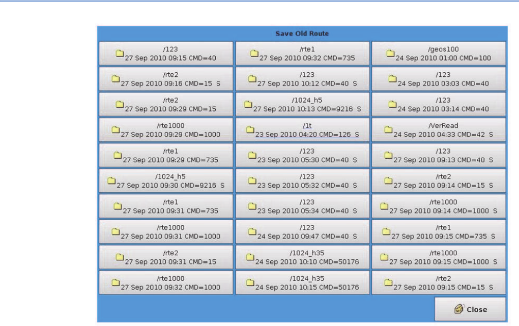
EA Mobile User Guide
7. Command mode
64
This will open the Save Old Route window.
Figure 7-5.
3. Select the route of interest and press that button.
For example, if you want to save the last route executed. In this example, it
would be the 3rd button in the second column. Always inspect each button
as the last executed can appear in any location.
The route will load and then be saved.
4. Press Okay on the bar graph once the route is saved.
Note: If you are operating the system with the EA_VID, an additional
bar graph window will open indicating the EA_Mobile is
awaiting data from the EA_VID. Once the EA_VID has loaded
the route the Okay button will become enabled and pressing
this button will allow you to continue.
Note: If an error message is displayed follow the message directions.
5. Press Close to return the EA_Mobile to the Route window.
Help window The Help window is accessed by pressing the Help button on the Main Menu and
provides online assistance via three buttons:
• About - Displays information about the EA_Mobile including version data
and build date.
• Guide - Offers brief operating instructions.

EA Mobile User Guide
7. Command mode
65
• Close - Closes the Help Window.
Figure 7-6.
About button
Pressing the About buttons displays the About window (Figure 7-7) that shows
the EA_Mobile version number, build date of the installed firmware, Elster logo
and address. See the below figure for an example of this window.

EA Mobile User Guide
7. Command mode
66
Figure 7-7.
• Press Close to return the EA_Mobile to the previous window.
Guide button
The Guide button opens a Quick Help Manual, which supplies some useful
information on how to use the EA_Mobile.
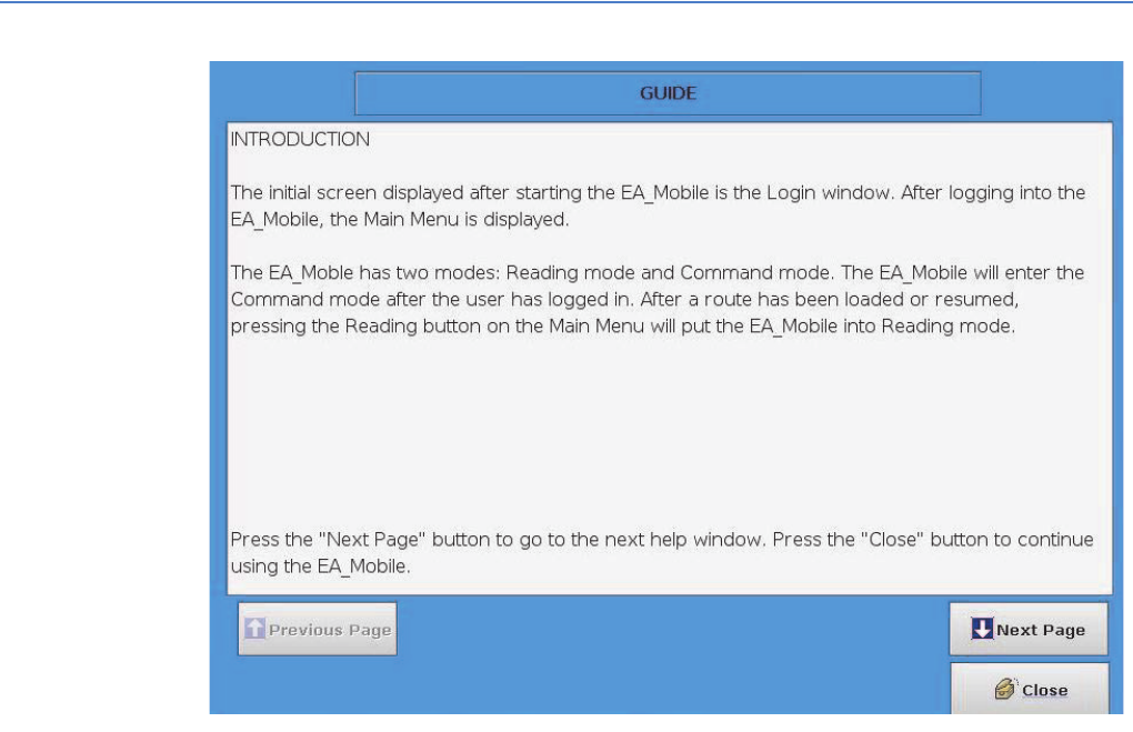
EA Mobile User Guide
7. Command mode
67
Figure 7-8.
To move through the listing, use the following keys:
• Previous Page - pages back to the previous page.
• Next page - advances to the next page.
• Close - closes this window.
Settings window The Settings window offers five buttons and a Close button as seen in Figure 7-9.
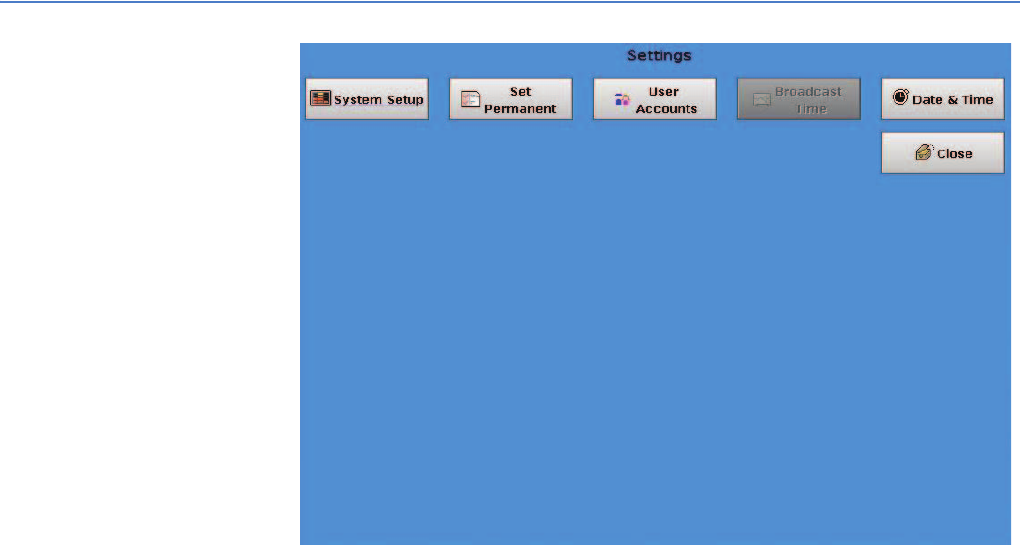
EA Mobile User Guide
7. Command mode
68
Figure 7-9.
The System Setup button allows for configuration of route related parameters
including Reading Mode, Display of Good Reads, Sound on Good Read, Reset
Tampers, Window Size, Sort Unread Display, and Monitor Unread Display.
The Set Perm button displays system usage, unit serial #, date last updated, date
of last service.
The User Accounts button allows the user to add, delete and modify users for this
EA_Mobile unit.
The Date & Time button allows user to configure the system data and time.
The Broadcast Time button is currently not implemented.
System Setup button
Pressing the System Setup button displays the System Setup window (Figure 7-10).
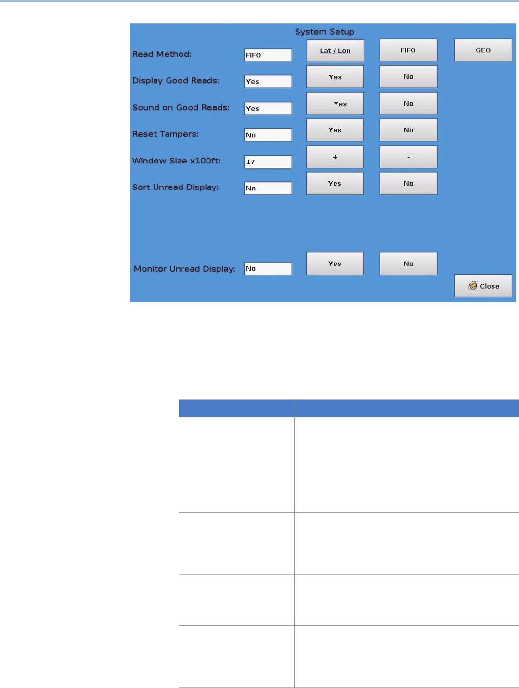
EA Mobile User Guide
7. Command mode
69
Figure 7-10.
To exit this screen and save the new settings, press the Close button.
Changing system settings
The table below describes each setting and tells you how to change the current
setting:
Item Description
Reading Method This option allows you to change the default Reading
mode:
• L/L (Lat/Lon)
•GEO
•FIFO
Press the relevant button to select the desired mode.
The new mode will be displayed in the white text area
following the Read Method.
Display Good Reads This option allows you to set up the EA_Mobile to display
endpoint data details (endpoint LAN ID, meter reading
and street address) after receiving a good reply.
• Press the Yes or No button after this option to set to
desired value.
Sound on Good Reads This option tells the EA_Mobile whether or not to beep
after each good read.
• Press the Yes or No button after this option to set to
desired value.
Reset Tampers This option determines whether or not the EA_Mobile will
automatically attempt to reset a tamper indication after it
receives a reply.
• Press the Yes or No button after this option to set to
desired value.

EA Mobile User Guide
7. Command mode
70
Set Perm button
The Set Perm button displays the Permanent Settings window (Figure 7-11) that
allows you to view permanent settings in the EA_Mobile’s non-volatile (saved
even when powered off) memory. These settings are not loaded from the USB
flash drive and, typically, never need to be changed.
Note: Only authorized personnel can change permanent settings by
entering the factory unlock password.
Do not use the Clear button unless you wish to reset all
parameters to default value!
Changing permanent settings
If you are authorized to change the settings in this option, use the following
procedure:
1. Obtain the factory unlock password from Elster Customer Support.
Customer Support will need the EA_Mobile’s serial number and the encrypt
key found on the Permanent Settings window of the EA_Mobile.
2. From the Main Menu, press the Settings button.
3. From the Settings window press the Set Perm. button.
The Permanent Settings window displays the current settings.
Window Size x 100 feet This option allows you to set the interrogation window
size for the Lat/Lon or GEO mode:
• Press the + or - buttons following this option to
increase/decrease the window size.
• The interrogation window is approximately an oval.
The size display is the radius in the forward direction
multiplied by 100 and by 50 to the side of the vehicle.
For example, if the window size is 12, meters up to
1200 feet in front or behind and up to 600 feet to either
side the vehicle will be read.
• Valid ranges are between 1 and 18.
Note: Elster recommends a distance of 1200 feet.
Sort Unread Display This option tells the EA_Mobile to sort unread endpoints
by distance from the EA_Mobile. With this turned on,
unread endpoints closest to the EA_Mobile will be listed
first and the farthest will be listed last.
• Press the Yes or No button after this option to set to
desired value.
Monitor Unread Display This allows you to set the EA_Mobile to alert you with an
audible alarm if an endpoint comes in and then exits the
interrogation window without being read.
Note: Applies only when in Lat/Lon or GEO mode.
• Press the Yes or No button after this option to set to
desired value.
Item Description
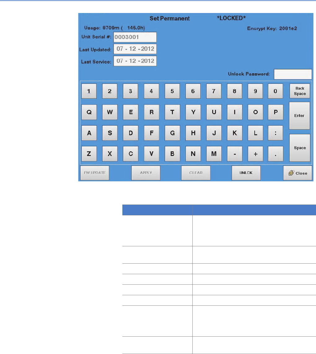
EA Mobile User Guide
7. Command mode
71
Figure 7-11.
The table below describes the permanent settings;
4. Press the UNLCK (Unlock) button to access the Unlock sequence.
5. Enter the Password supplied by Elster in the Password field on the screen
and then press Enter button.
The top line of the screen will now display the message EA_Mobile
Permanent Settings *UNLOCKED*.
6. Press the Enter button on the LCD touch screen display and scroll to the
parameter you wish to change.
Item Description
EA_Mobile Permanent
Settings
(Locked/Unlocked) The heading line on this screen
indicates whether this function is Locked (as it will
be under all normal conditions) or Unlocked (by
special factory password authorization only).
Usage The total number of minutes (also shown in hours)
that the EA_Mobile has been in the reading mode.
Unit Serial # Serial number of the EA_Mobile.
Last Updated Date the EA_Mobile firmware was last updated.
Last Service Date of latest factory service to EA_Mobile.
Encrypt Key This field is for factory use only.
Unlock Password Password for unlocking Permanent Settings
window.
Note: Please contact Elster Customer Support if this
password is needed.
Close Press to exit the Set Perm. window and return to the
Settings window.
EA Mobile User Guide
7. Command mode
72
7. Change the desired setting by selecting alphabetic characters on the LCD
touch screen display.
Caution: The CLEAR button on the LCD touch screen will clear/reset all
parameters to default values. Do NOT press CLEAR to correct
individual entries.
8. To correct an entry, use the Back Space button on the LCD touch screen
display.
Caution: The FW UPDATE button on the LCD touch screen display will try
to update the firmware, do not press this button unless
instructed to do so by Customer Support.
9. When you are satisfied with the entered changes and settings, press the
APPLY button on the LCD touch screen display to apply the new settings and
permanently reset the default values in EA_Mobile memory.
10.Press the Close button to exit this function and return to the Settings window.
Note: Closing the window with out hitting the APPLY button will result
in the settings returning to their original value and all changes
will be lost.
User Accounts button
The User Accounts button displays the User Account window (Figure 7-12) that
allows the operator to add, modify and delete user accounts.
There are a maximum of 25 user accounts.
Note: The initial user name is ‘ELSTER’ and the initial password is
‘357837’. For security purposes, this user account may be
removed after new user accounts are created and logged in.
Note: Make sure to enter the user name in all capital letters.
Note: This User Account can be deleted.
Note: The account for a user that is currently logged in cannot be
deleted.
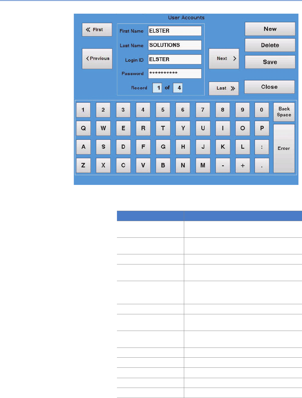
EA Mobile User Guide
7. Command mode
73
Figure 7-12.
The table below describes the permanent settings;
Item Description
First Name Indicates the first name for the selected user
account.
Last Name Indicates the last name for the selected user
account.
Login ID Indicates the Login ID for the user.
Password Indicates the Password for the user.
Note: The password is hidden.
Record Identifies the list number for the selected user
account and indicates the total number of user
accounts defined in the EA_Mobile unit.
First Displays the first user account in the list.
Previous Displays the previous user account from the
selected user account.
Next Displays the next user account from the selected
user account.
Last Displays the last user account in the list.
New Allows you to add a new user account to the list.
Delete Allows you to delete the selected user account.
Save Saves changes to user accounts.
Close Closes the User Account window.
EA Mobile User Guide
7. Command mode
74
Adding a new user
To add a new user account:
1. Press the New button.
2. Use the keyboard to enter new user data:
a. The First Name can be 6 characters.
b. The Last Name can be up to 10 characters.
c. The Login ID can be up to 6 characters.
d. Passwords must be between 6 and 10 characters.
3. Press Save to save the changes.
Changing an existing user
To modify an existing account:
1. Locate the record for the user account to be modified using the First, Last,
Next and Previous buttons.
Note: You cannot change a logged in user account.
2. Click in the text box you want to change.
3. Use the keyboard to make the desired changes:
a. Use the Back Space button to delete the last character in the field
Note: Using the Back Space button in the Password text box will
delete the password.
b. Use the keyboard to enter new data:
1) The First Name can be 6 characters.
2) The Last Name can be up to 10 characters.
3) The Login ID can be up to 6 characters.
4) Passwords must be between 6 and 10 characters.
4. Press Save to save the changes.
Deleting an existing user
To delete an existing user:
1. Locate the record for the user account to be deleted using the First, Last,
Next and Previous buttons.
Note: You cannot delete a logged in user account.
2. Press Delete.
3. Press Save to save the changes.
Date & Time button
Pressing the Date & Time button displays the Set System Time and Date window
(Figure 7-13). Using the + and - buttons you can change the time (Hours, Minutes,
and Seconds) and the date (Month, Day, and Year) as maintained by the
EA_Mobile’s CPU.
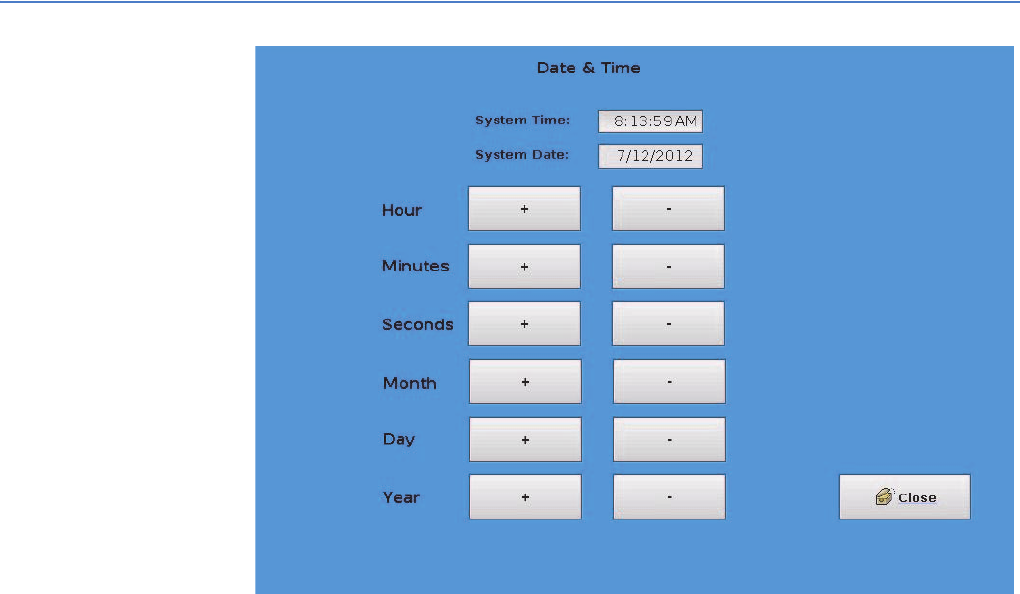
EA Mobile User Guide
7. Command mode
75
Figure 7-13.
Changing the date or time
To change the date or time:
1. Press the + or -buttons to increase or decrease, respectively, the value you
wish to change.
For example, to increase the hour from 5 to 6 simply press the + button next
to the Hour label.
2. When you are satisfied with the system time and date settings, press the
Close button to exit this screen and return to the Settings window.
Note: Since the system clock continues to run while setting the time,
when setting the seconds decreasing 1 second may result in no
change, because the system time increased 1 second during
the time it took you to decrease it by 1 second.
Summary window The Summary window supplies buttons to view the current route data according
to various different categories. This can help you assess your progress and
analyze route details and characteristics.
The Summary window (Figure 7-14) can be opened by clicking on the Summary
button in the Main Menu.
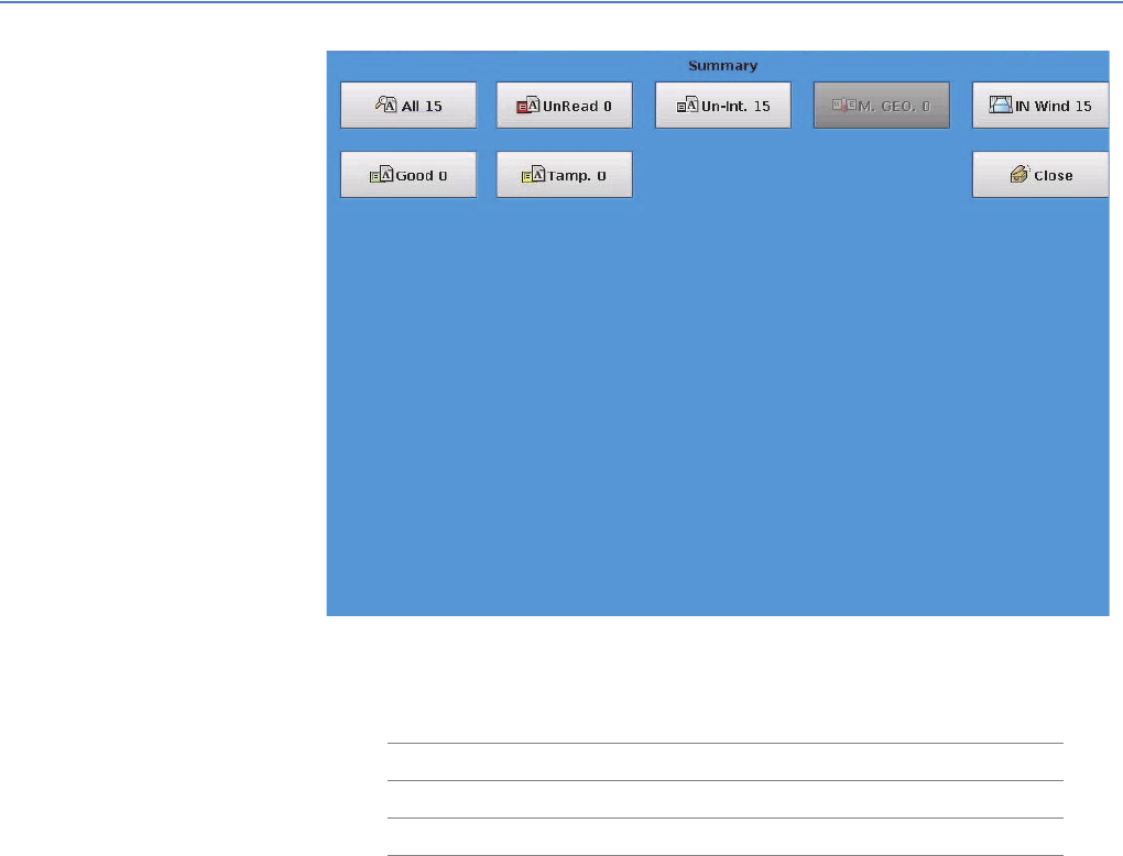
EA Mobile User Guide
7. Command mode
76
Figure 7-14.
The Summary window offers five views of the current route’s accumulated data
represented by the following buttons:
Note: The M. GEO button and IN Wind button are functional on the
EA_VID and not available on the EA_Mobile.
All button
The All button indicates the total number of endpoints in the route. When this
button is selected, the screen displays the data for all endpoints in the route,
regardless of read condition or proximity.
UnRead button
The UnRead button indicates the number of unread endpoints in the route. This
button displays all unread endpoints in the route regardless of proximity. For this
option, the Reading column changes to a Distance column, showing the
endpoint’s distance from the EA_Mobile. The Status column displays NO_RD.
Endpoints are listed in order from the closest to the farthest away. Distance is
measured in feet up to 5280 then begins with miles up to 99.9. Any UNRD without
a Lat/Lon will be indicated at a distance of 99.9 miles.
•All button •UnRead button •Un-int button
•M. GEO button •In Wind button •Good button
•Tamp. button • Close button
EA Mobile User Guide
7. Command mode
77
Un-int button
The Un-int button indicates the number of uninterrogated endpoints in the route.
This button displays all endpoints that have never been interrogated in the current
session. This refers to any endpoints the EA_Mobile has not yet broadcast an
interrogation signal. (This means that in FIFO mode, there should be no
interrogated endpoints after the first pass down the route list.)
M. GEO button
The M. GEO button displays the number of unread GEO accounts. This button
disable and ghosted out.
In Wind button
The In Wind button indicates the number of unread transponder in the window.
This button display all transponder that are with in the interrogation window and
have not completed or are bad reads.
Good button
The Good button indicates the number of endpoints successfully responding to
the interrogation signal. This button displays all endpoints that have replied
successfully to an interrogation, including tampered units.
Tamp. button
The Tamp. button indicates the number of endpoints returning a tamper status.
This button displays all endpoints that have returned a tamper status, regardless
of whether or not the tamper has been reset.
Note: The Tamp. button does not apply to electricity meters.
Viewing a summary
When you select one of the five summary buttons the LCD touch screen will
display a screen like the one shown below (in this example, the All button has
been selected).
EA Mobile User Guide
7. Command mode
78
Figure 7-15.
The top portion of the screen displays the sequential summary Entry number,
endpoint/meter street Address, endpoint Serial Number, endpoint Status and
meter Reading.
Note: For the UnRead button, the Reading column is replaced with a
Distance column.
The All number indicates the number of endpoint/entries in the selected category.
In the case of the display example shown above, there are a total of 4500 entries,
only 28 of which can be seen at this time.
The bottom of the screen displays the following three buttons:
• UP - scrolls to the previous window
• DOWN - scrolls to the next window
• Close - exits the screen and returns to the Summary window.
Endpoint status codes
The following table lists the endpoint status codes and their definitions for gas
and water endpoint. For electricity endpoints, a HEX value will be displayed
indicating status. These status Output Codes are used in the VAN file only. Various
screens on the LCD touch screen monitor use text mnemonics for some of the
same indications.
In the table below:
•Status Code reflects various combinations of conditions including:
interrogated/uninterrogated, good/bad/no read, tamper evidence, tamper
reset succeeded/failed/pending and bad checksum (data integrity checks)
on meter reading, serial number or both.
•Simple description describes the abbreviations used in the Status Code
column.

EA Mobile User Guide
7. Command mode
79
•Output Code is a code used by the EA_Mobile’s processor to classify read
conditions in the output file written to the USB flash drive when a route is
completed and saved.
•Detailed description describes the conditions identified by each status type,
and in some cases, possible causes and solutions.
Status Code Simple description Output
Code
Detailed description
UNINT Uninterrogated 10 The endpoint has never been interrogated because it does not appear
within the interrogation window.
G_NT Good, not tampered 01 Endpoint has replied with a good read, no temper condition reported.
G_NR Good, tampered, not reset 03 Endpoint has answered with a good reply and is showing a tamper status
G_TR Good, tamper reset 07 Endpoint has answered with a good replay and was showing a tamper
status. EA_Mobile has successfully reset tamper condition.
G_T_RF Good, tamper reset failed 0B Endpoint has answered with a good reply and is showing a tamper status
but the EA_Mobile cannot reset the tamper condition (possibly because
the endpoint is still in the condition that triggered the tamper message).
G_T_RP Good, tamper reset pending 0F Endpoint has answered with a good reply and is showing a tamper status
but the EA_Mobile was not able to verify the tamper condition was reset.
This may occur if the EA_Mobile goes out of range while interrogating and
before verifying the tamper reset.
NO_RD EA_Mobile received no reply
from endpoint
20 Endpoints which have not processed all outstanding command or the
endpoint failed to read for some reason.
BAD_RD Bad read 40 Endpoint has been interrogated and the receiver was able to lock on to the
incoming data but the BCH error detection test has failed. This may occur if
the EA_Mobile is in an area of strong interference and is usually corrected
when the EA_Mobile gets closer to the endpoint.
BAD_MR Bad meter reading
checksum
41 Endpoint has answered with an indication that the meter reading
checksum has failed. This may be the result of a temporary power
fluctuation. The endpoint should be checked and reprogrammed.
Manually verify and enter meter reading.
BAD_ID Bad serial number
checksum
42 Endpoint has answered with an indication that the serial number
checksum has failed. This may be the result of a temporary power
fluctuation. The endpoint should be checked and reprogrammed.
Manually verify and enter meter reading.
BAD_B2 Both checksums bad 43 Endpoint has answered with an indication that both the meter reading and
serial number checksums have failed. This may be the result of a
temporary power fluctuation. The endpoint should be checked and
reprogrammed. Manually verify and enter meter reading.
N_T_RP No read, tamper reset
pending
2F Endpoint has answered with a good reply and is showing a tamper status
but during the tamper reset verification, the endpoint reply resulted in a
NO_RD status. The tamper condition may or may not still exist. (See NO_RD
description.)
B_T_RP Bad read, tramper reset
pending
4F Endpoint has answered with a good reply and is showing a tamper status
but during the tamper reset verification, the endpoint reply resulted in a
BAD_RD status. The tamper condition may or may not still exist. (See
BAD_RD description)

EA Mobile User Guide
7. Command mode
80
Tools window The Tools button on the Main Menu displays the Tools window. The Tools window
contains buttons that allow you to troubleshoot system components, modify
certain parameters, and view additional data detail stored in the EA_Mobile’s
memory.
Figure 7-16.
The buttons available under the Tools window are described below.
Tx On button
Turns the transmitter ON and OFF.
Sync VID button
Sends currently read endpoints to the EA_VID to allow the EA_VID screen to
update (when EA_VID is connected).
Troubleshoot button
Pressing the Troubleshoot button opens a new window (Figure 7-17) which allows
the user to troubleshoot endpoints which are not reading.
EA Mobile User Guide
7. Command mode
81
Figure 7-17.
• Use the keypad to enter a new UID and LAN ID.
• Press the Send UID & LAN ID button to have the transceiver request the
specified endpoint to start sending message count data.
The message count data includes: transmitted messages, good messages
received, bad messages received, wake-up tones received, wake-up tones
tried, and percent good.
• Press the Reset Counts button to reset the counts to zero.
The figure below (Figure 7-18) is an example of the Reset Counts command
processing.
EA Mobile User Guide
7. Command mode
82
Figure 7-18.
The figure below is an example of the Reset Counts failing.
Figure 7-19.
EA Mobile User Guide
7. Command mode
83
Note: If no data is received from the selected endpoint, the endpoint is
either out of range or it is bad.
Route Scan button
Not currently implemented.
Power Off button The Power Off button can be used to power off the system. This button opens a
message window informing the user that the system is about to power off and
giving the user a choice between continuing and canceling the power off. If a
route is loaded and not saved, this message will also inform the user of this.
• Pressing the Okay button will result in the system powering off.
• Pressing the Cancel button will cancel the power off and allow the user to
continue using the EA_Mobile.
Note: The EA_Mobile stores the last 30 routes loaded so that
powering off without saving does not result in lost data. These
routes can be saved using the Save Old Route button or to
continue reading the route can be resumed using the Resume
Route button.

ATROUBLESHOOTING THE
EA_MOBILE
The following table offers troubleshooting assistance for many problems you may
encounter. For those symptoms or solutions not covered by this table, contact:
Elster
Customer Service
Phone 800-786-2215 FAX 919-250-5439
Business Hours: Monday-Friday 8am-5pm [Eastern Time]
Warning: The EA_Mobile contains NO user serviceable parts or
adjustment. Tampering with such or breaking tamper seals
may prove harmful to personnel or equipment and voids the
warranty.
Table A-1. Global Positioning System (GPS)
Symptom Possible Cause Solutions
GPS not active Insufficient time elapsed since being moved
from its last known position and reactivated.
GPS requires up to 5 minutes (30 minutes for
first time initialization) to achieve maximum
satellite communications.
Wait 30 minutes or until a minimum of 4 satellites in
use, are displayed on handheld terminal or
EA_VID.
GPS active but not
providing good L/L
coordinates in FIFO mode
Inadequate number of satellites for FIFO mode
(minimum of 6 required).
Wait 30 minutes or until a minimum of 6 satellites in
use, are displayed on handheld terminal or
EA_VID.
GPS active but providing
poor L/L readings
Interference is caused by tall buildings,
overhanging trees or other obstacles.
Continue reading. When coverage resumes, the
unit will continue operating in that mode.
Receiver is too close to the other antennas Reposition GPS receiver and/or antennas to allow
for at least 2 feet separation from the GPS receiver.
Loss of GPS signal GPS cable disconnected or improperly
connected.
Properly connect cable to GPS receptacle on
EA_Mobile back.
GPS cable crimped or crushed. Reroute cable. If damaged, contact American
Meter for replacement unit.
Interference is caused by tall buildings,
overhanging trees or other obstacles.
Continue reading. When coverage resumes, the
unit will continue operating in FIFO mode.
GPS offline Go to //FIFO or GEO?// mode and continue
operating.
EA Mobile User Guide

EA Mobile User Guide
A. Troubleshooting the EA_Mobile
85
GPS status -” on status line GPS has become unable to compute its
position.
The EA_Mobile automatically switches to FIFO
Mode. Continue in FIFO until the GPS resumes
function. The EA_Mobile will switch back to the
mode in effect prior to the outage.
Table A-1. Global Positioning System (GPS)
Symptom Possible Cause Solutions
Table A-2. Indicator Warnings
Symptom Possible Cause Solutions
No EA_Mobile indicator
lights are solid Green
EA_Mobile is not receiving power. See EA_Mobile is not receiving power”
troubleshooting tips below.
LINE light is flashing Green
or is Red
Line voltage insufficient because too many
accessories are turned on, draining vehicle
power.
Turn off non-essential accessories (radio, tape
player, CD, etc.)
Line voltage insufficient because power cable
has become disconnected.
Check the EA_Mobile power cable and make sure
both ends are properly attached at EA_Mobile and
at the accessory/cigarette lighter receptacle.
Line voltage insufficient because vehicle’s
accessory/cigarette lighter fuse has blown.
Turn off EA_Mobile and replace fuse.
Line voltage insufficient because vehicle’s
alternator is unable to produce adequate
operating current.
Turn off EA_Mobile and have vehicle serviced.
BATT light is flashing Green
or is solid Red
EA_Mobile internal battery has dropped to an
unusable voltage.
Allow unit to charge between uses.
TEMP light is flashing
Green or is Solid Red
The EA_Mobile internal temperature has
exceeded the threshold because the cooling
fan is blocked or obstructed.
Remove any clogs from the fan intake and/or
reposition the EA_Mobile to allow proper air
circulation to the cooling fan.
The EA_Mobile internal temperature has
exceeded the threshold because the cooling
fan has quit working.
Contact Elster Solutions.
The EA_Mobile internal temperature has
exceeded the threshold because the ambient
temperature in the vehicle is too high.
Cool off the vehicle by opening windows, moving
vehicle out of direct sun, and/or by adjusting the
heater or air conditioning thermostat.
ACTIVITY light is flashing Normal operating condition, indicating this
transceiver channels is actively receiving
endpoint data.
n/a

EA Mobile User Guide
A. Troubleshooting the EA_Mobile
86
Table A-3. Displayed Status Reports & Messages
Symptom Possible Cause Solutions
NO_RD status returned Endpoint is still too far from EA_Mobile for
robust read.
Move EA_Mobile closer to endpoint and continue
interrogation.
RF-opaque (metallic) objects are blocking
signal path.
Move EA_Mobile or objects and continue
interrogation.
Endpoint is faulty Replace endpoint.
BAD_RD status returned EA_Mobile is in area of strong interference
from an outside source.
Move the EA_Mobile closer to the endpoint and
continue interrogation.
Endpoint is in area of interference from an
outside source.
Determine source of interference and correct.
N_T_RP status returned Condition causing tamper condition still exists. Check meter and endpoint. Correct condition
causing tamper status.
During attempt to verify tamper reset,
EA_Mobile moved out of range before reset
was verified.
Move EA_Mobile closer and continue interrogation.
B_T_RP status returned Condition causing tamper condition still exists. Check meter and endpoint. Correct condition
causing tamper status.
During attempt to verify tamper reset,
EA_Mobile moved into an area of strong
interference from outside source.
Move the EA_Mobile closer to the endpoint and
continue interrogation.
Endpoint is in area of interference from an
outside source.
Determine source of interference and correct.
Table A-4. Operational & Miscellaneous
Symptom Possible Cause Solutions
Cannot access the
Settings/System Setup
window
User is not authorized to access this function
and does not have the password.
Contact your supervisor or Elster Solutions.
Four previous failed password attempts have
locked out further access to this function.
Restart the EA_Mobile and enter the correct
password at the prompt for this screen.
Cannot change system
date and time via Settings/
Date & Time window
User is not authorized to access this function
and does not have the password.
Contact your supervisor or Elster Solutions.
Tamper reset not working
(for gas and water
endpoints only)
Condition causing tamper condition still exists. Check meter and endpoint. Correct condition
causing tamper status.
EA_Mobile went out of range before tamper
reset verified.
Move close to endpoint and continue interrogation.
Endpoint is faulty. If no tamper condition exists, replace endpoint.
Reset tamper function not enabled on
EA_Mobile.
Contact your supervisor or Elster Solutions.

EA Mobile User Guide
A. Troubleshooting the EA_Mobile
87
Endpoints can be read in
FIFO but not in Lat/Lon
GPS is not providing adequate GPS data. Verify the GPS is in Active status and has satellite
acquisition. If not, move EA_Mobile and try again.
Endpoint Lat/Lon coordinates are incorrect or
not valid.
Check Summary Command/INWIN button for list of
endpoints in Lat/Lon Mode are considered to be in
the interrogation window. If the desired endpoints
are not in the list, interrogate the endpoints using
FIFO Mode and correct the coordinates. See
Chapter 6, “Reading mode.”
Table A-4. Operational & Miscellaneous
Symptom Possible Cause Solutions

BGUI BUTTONS
Notes on GUI buttons In the EA_Mobile there are three types of buttons: normal, disabled and blocked.
Normal buttons can be pressed and their functionally will be implemented. For
example the Close button will close the current window.
Disabled buttons (as shown below) indicate the functionality is not available at
this time. The Sync EA_VID button is only available after a route is loaded and
running with a EA_VID.
The following buttons are disabled until a route is loaded:
• On the Main Menu:
•Reading
•Summary
• On the Route Menu
• Save Current Route
• On the Tools Menu
• Sync EA_VID - EA_VID must also be present
Blocked buttons were added for future development and their functionality is not
currently available in this release. For example, the Route Scan button is available
on the EA_VID, but has not yet been implemented in the EA_Mobile.
The following buttons have been added for future functionality:
• On the Settings Menu
• Broadcast Time
• On the Summary Button
• M. Geo - available on the EA_VID
• On the Tools Menu
• Route Scan - available on the EA_VID
EA Mobile User Guide
EA Mobile User Guide
B. GUI buttons
89

© 2012 by Elster. All rights reserved.
No part of this software or documentation may be reproduced, transmitted, processed or recorded by any
means or form, electronic, mechanical, photographic or otherwise, translated to another language, or be
released to any third party without the express written consent of Elster.
4 December 2012
Elster Solutions
208 South Rogers Lane
Raleigh NC 27610-2144
EnergyAxis Support +1 866 554 9007
www.elster.com