Elster Solutions HHI04 Hand Held Interrogator User Manual
Elster Solutions, LLC Hand Held Interrogator Users Manual
Users Manual

Elster Handhelds
User Guide 3Contents
Contents
FCC and Industry Canada compliance . . . . . . . . . . . . . . . . . . .7
Disclaimer of warranties and limitation of liability . . . . . . . . . .8
Safety information . . . . . . . . . . . . . . . . . . . . . . . . . . . . . . . . . . . .8
Revisions to this document . . . . . . . . . . . . . . . . . . . . . . . . . . . . .9
1 Introduction . . . . . . . . . . . . . . . . . . . . . . . . . . . . . . . . . . . . . . . . . . 10
About handheld devices . . . . . . . . . . . . . . . . . . . . . . . . . . . . . . 10
About This manual . . . . . . . . . . . . . . . . . . . . . . . . . . . . . . . . . . 10
Audience . . . . . . . . . . . . . . . . . . . . . . . . . . . . . . . . . . . . . . . 10
New users . . . . . . . . . . . . . . . . . . . . . . . . . . . . . . . . . . . . . . 10
Existing users . . . . . . . . . . . . . . . . . . . . . . . . . . . . . . . . . . . . 11
Automatic meter reading . . . . . . . . . . . . . . . . . . . . . . . . . . . . . 11
Basic AMR components . . . . . . . . . . . . . . . . . . . . . . . . . . . 11
Overview . . . . . . . . . . . . . . . . . . . . . . . . . . . . . . . . . . . . . . . 11
2 About handheld devices . . . . . . . . . . . . . . . . . . . . . . . . . . . . . . . 13
PI 500 handheld . . . . . . . . . . . . . . . . . . . . . . . . . . . . . . . . . . . . . 13
Dap CE5240X handheld computer specifications . . . . . . 13
Using an external antenna . . . . . . . . . . . . . . . . . . . . . . . . 14
Safe RF exposure using external antenna . . . . . . . . . . . 14
More about Dap CE5240x . . . . . . . . . . . . . . . . . . . . . . . . . 14
evoWalk and PI 900 handhelds . . . . . . . . . . . . . . . . . . . . . . . . 14
Radix specifications . . . . . . . . . . . . . . . . . . . . . . . . . . . . . . 15
Safe RF exposure using external antenna . . . . . . . . . . . 15
More about Radix . . . . . . . . . . . . . . . . . . . . . . . . . . . . . . . . 15
Basic operation . . . . . . . . . . . . . . . . . . . . . . . . . . . . . . . . . . . . . 16
Transmission accuracy . . . . . . . . . . . . . . . . . . . . . . . . . . . . . . . 16
Navigating . . . . . . . . . . . . . . . . . . . . . . . . . . . . . . . . . . . . . . . . . 16
PI 500 installation tool . . . . . . . . . . . . . . . . . . . . . . . . . . . . . . . . 17
PI 900 installation tool . . . . . . . . . . . . . . . . . . . . . . . . . . . . . . . . 17
Database warning . . . . . . . . . . . . . . . . . . . . . . . . . . . . . . . . . . . 17
3 Handheld operation. . . . . . . . . . . . . . . . . . . . . . . . . . . . . . . . . . . 18
Commonly used keys . . . . . . . . . . . . . . . . . . . . . . . . . . . . . . . . 18
<Esc> . . . . . . . . . . . . . . . . . . . . . . . . . . . . . . . . . . . . . . . . . . 19
<Enter> . . . . . . . . . . . . . . . . . . . . . . . . . . . . . . . . . . . . . . . . . 19
Arrow keys . . . . . . . . . . . . . . . . . . . . . . . . . . . . . . . . . . . . . . 19
<Tab> . . . . . . . . . . . . . . . . . . . . . . . . . . . . . . . . . . . . . . . . . . 19
Entering responses (Yes/No) . . . . . . . . . . . . . . . . . . . . . . . 19
Using the stylus . . . . . . . . . . . . . . . . . . . . . . . . . . . . . . . . . . . . 20
Reading meters . . . . . . . . . . . . . . . . . . . . . . . . . . . . . . . . . . . . 20
Turning the device on and off . . . . . . . . . . . . . . . . . . . . . . . . . 20
Dap . . . . . . . . . . . . . . . . . . . . . . . . . . . . . . . . . . . . . . . . . . . 20
Radix . . . . . . . . . . . . . . . . . . . . . . . . . . . . . . . . . . . . . . . . . . 20
Charging the device . . . . . . . . . . . . . . . . . . . . . . . . . . . . . . . . . 21
Dap . . . . . . . . . . . . . . . . . . . . . . . . . . . . . . . . . . . . . . . . . . . . 21
Elster Handhelds
User Guide 4Contents
Radix . . . . . . . . . . . . . . . . . . . . . . . . . . . . . . . . . . . . . . . . . . . 21
Resetting the handheld device . . . . . . . . . . . . . . . . . . . . . . . . . 21
Dap . . . . . . . . . . . . . . . . . . . . . . . . . . . . . . . . . . . . . . . . . . . . 21
Radix . . . . . . . . . . . . . . . . . . . . . . . . . . . . . . . . . . . . . . . . . . . 21
Logging in to the handheld . . . . . . . . . . . . . . . . . . . . . . . . . . . . 21
Holding the handheld . . . . . . . . . . . . . . . . . . . . . . . . . . . . . . . 22
For meter reading . . . . . . . . . . . . . . . . . . . . . . . . . . . . . . . 22
For RTM installation . . . . . . . . . . . . . . . . . . . . . . . . . . . . . . 22
4 About Interrogator software . . . . . . . . . . . . . . . . . . . . . . . . . . . 23
Selecting a route . . . . . . . . . . . . . . . . . . . . . . . . . . . . . . . . . . . 24
RM Communication . . . . . . . . . . . . . . . . . . . . . . . . . . . . . . . . . 24
Viewing handheld configuration . . . . . . . . . . . . . . . . . . . . . . 25
Updating handheld configuration . . . . . . . . . . . . . . . . . . 26
Exiting Elster Interrogator . . . . . . . . . . . . . . . . . . . . . . . . . . . . . .27
5 Reading accounts . . . . . . . . . . . . . . . . . . . . . . . . . . . . . . . . . . . 29
Navigating accounts . . . . . . . . . . . . . . . . . . . . . . . . . . . . . . . . 29
<Esc> . . . . . . . . . . . . . . . . . . . . . . . . . . . . . . . . . . . . . . . . . 29
<Enter> . . . . . . . . . . . . . . . . . . . . . . . . . . . . . . . . . . . . . . . . 29
<Up> and <Down> arrow keys . . . . . . . . . . . . . . . . . . . 29
Reading an account . . . . . . . . . . . . . . . . . . . . . . . . . . . . . . . . 29
Performing a default read of an unread account . . . . . 30
Performing a manual index reading . . . . . . . . . . . . . . . . 31
Moving on to the next account . . . . . . . . . . . . . . . . . . . . 32
Additional account reading options . . . . . . . . . . . . . . . . . . . 32
Clearing index read . . . . . . . . . . . . . . . . . . . . . . . . . . . . . 32
Forcing unattempted account . . . . . . . . . . . . . . . . . . . . . 32
Adding a trouble code . . . . . . . . . . . . . . . . . . . . . . . . . . . 33
Adding a skip code . . . . . . . . . . . . . . . . . . . . . . . . . . . . . . 33
Entering messages for an account . . . . . . . . . . . . . . . . . 34
Setting the resequence flag . . . . . . . . . . . . . . . . . . . . . . . 35
Removing a resequence flag . . . . . . . . . . . . . . . . . . . . . . 36
Performing a multiple parameter RF read . . . . . . . . . . . 36
Performing a single history/TOU RF read . . . . . . . . . . . . 39
Performing a general index RF read . . . . . . . . . . . . . . . . 39
Jumps . . . . . . . . . . . . . . . . . . . . . . . . . . . . . . . . . . . . . . . . . . . . . 41
Viewing Account Details screen . . . . . . . . . . . . . . . . . . . . 41
Jumping to the beginning of current route . . . . . . . . . . . . 41
Jumping to the end of current route . . . . . . . . . . . . . . . . . 41
Jumping to a specified sequence number . . . . . . . . . . . . 41
Jumping to the next route . . . . . . . . . . . . . . . . . . . . . . . . . . 41
Jumping to the previous route . . . . . . . . . . . . . . . . . . . . . . 41
Jumping to next unread account in the current route . . 42
Searching the current route . . . . . . . . . . . . . . . . . . . . . . . . . . 42
Performing a search . . . . . . . . . . . . . . . . . . . . . . . . . . . . . 42
Example Search - Address . . . . . . . . . . . . . . . . . . . . . . 43
Example Search - Customer . . . . . . . . . . . . . . . . . . . . . 44
Viewing additional information . . . . . . . . . . . . . . . . . . . . . . . 45
Viewing Help and available commands . . . . . . . . . . . . 46
Viewing Routes Selection screen . . . . . . . . . . . . . . . . . . . 46
Viewing Route Summary screen . . . . . . . . . . . . . . . . . . . 46
Viewing Account Details screen . . . . . . . . . . . . . . . . . . . .47
Viewing Instruction Code screen . . . . . . . . . . . . . . . . . . . 48
Viewing Location Code screen . . . . . . . . . . . . . . . . . . . . 48
Viewing Error Log screen . . . . . . . . . . . . . . . . . . . . . . . . . 49
Viewing Trouble Code screen . . . . . . . . . . . . . . . . . . . . . 50
Viewing appointments . . . . . . . . . . . . . . . . . . . . . . . . . . . . . . 50
Elster Handhelds
User Guide 5Contents
6 Using the VersaProbe . . . . . . . . . . . . . . . . . . . . . . . . . . . . . . . . 52
Configuring a VersaProbe connection . . . . . . . . . . . . . . . . . . 52
Serial communication mode . . . . . . . . . . . . . . . . . . . . . . 52
Bluetooth communication mode . . . . . . . . . . . . . . . . . . . 53
Reading using a VersaProbe . . . . . . . . . . . . . . . . . . . . . . . . . 55
Establishing the VersaProbe connection . . . . . . . . . . . . 55
Reading a meter . . . . . . . . . . . . . . . . . . . . . . . . . . . . . . . . 56
7 Installing RTMs . . . . . . . . . . . . . . . . . . . . . . . . . . . . . . . . . . . . . . 59
Installing RTMs using the PI 500 . . . . . . . . . . . . . . . . . . . . . . . 59
Changing out meters and indexes . . . . . . . . . . . . . . . . . 59
Changing out a meter . . . . . . . . . . . . . . . . . . . . . . . . . . 60
Changing out an index . . . . . . . . . . . . . . . . . . . . . . . . . . 61
Installing an RTM . . . . . . . . . . . . . . . . . . . . . . . . . . . . . . . . 62
Water meter RTM installation display . . . . . . . . . . . . . 63
Gas meter RTM installation display . . . . . . . . . . . . . . . 63
Programming an RTM . . . . . . . . . . . . . . . . . . . . . . . . . . . 66
Checking subcounts . . . . . . . . . . . . . . . . . . . . . . . . . . . 66
Programming the RTM . . . . . . . . . . . . . . . . . . . . . . . . . 66
Using the scanner . . . . . . . . . . . . . . . . . . . . . . . . . . . . . . . .67
Taking GPS coordinates . . . . . . . . . . . . . . . . . . . . . . . . . . .67
Automatically . . . . . . . . . . . . . . . . . . . . . . . . . . . . . . . . . 68
Manually . . . . . . . . . . . . . . . . . . . . . . . . . . . . . . . . . . . . . 68
Installing EnergyAxis gas modules using the PI 900 . . . . . . 69
Checking subcounts . . . . . . . . . . . . . . . . . . . . . . . . . . . . 71
Programming the RTM . . . . . . . . . . . . . . . . . . . . . . . . . .72
8 RTM Verification . . . . . . . . . . . . . . . . . . . . . . . . . . . . . . . . . . . . . .76
Reading a meter with verification . . . . . . . . . . . . . . . . . . . . . . .76
Programming for verification . . . . . . . . . . . . . . . . . . . . . . .78
After failed verification . . . . . . . . . . . . . . . . . . . . . . . . . . .78
After successful verification . . . . . . . . . . . . . . . . . . . . . . .79
9 Communicating with Route Manager . . . . . . . . . . . . . . . . . . . 80
Establishing communications . . . . . . . . . . . . . . . . . . . . . . . . . 80
Downloading routes from Route Manager to device . . . . . . 82
Uploading routes from device to Route Manager . . . . . . . . 83
Removing routes from the handheld device . . . . . . . . . . . . . 83
After a successful upload . . . . . . . . . . . . . . . . . . . . . . . . . 83
Without receiving the routes first . . . . . . . . . . . . . . . . . . . 83
Updating handheld files . . . . . . . . . . . . . . . . . . . . . . . . . . . . . 83
10 Setting up devices in Route Manager . . . . . . . . . . . . . . . . . . . 85
Handheld device properties . . . . . . . . . . . . . . . . . . . . . . . . . . 85
VersaProbe properties . . . . . . . . . . . . . . . . . . . . . . . . . . . . . . 86
Scanner and GPS properties . . . . . . . . . . . . . . . . . . . . . . . . . . .87
A Accelerator keys for meter reading . . . . . . . . . . . . . . . . . . . . . 89
B Accelerator keys for installing RTMs . . . . . . . . . . . . . . . . . . . . . 90
C Troubleshooting . . . . . . . . . . . . . . . . . . . . . . . . . . . . . . . . . . . . . . 91
General troubleshooting . . . . . . . . . . . . . . . . . . . . . . . . . . . . . . 91
Elster Handhelds
User Guide 6Contents
Trouble in connecting the device to Route Manager . . . . . . . 91
D Programming Pre Gen 5 RTMs. . . . . . . . . . . . . . . . . . . . . . . . . 92
Gen 2 RTMs (FCC ID G8J3GNAMR8) . . . . . . . . . . . . . . . . . . . . 92
Gen 2.5 water pit RTMs (FCC ID G8JPIT25) . . . . . . . . . . . . . . 92
Gen 2.5 water remote RTMs (FCC ID G8JGEN25) . . . . . . . . . 92
Gen 3.x water remote RTMs (FCC ID G8JGEN03) . . . . . . . . . 92
Gen 3.x gas remote RTMs (FCC ID G8JGEN03) . . . . . . . . . . . 93

Elster Handhelds
User Guide 7.
FCC and Industry Canada compliance
Compliance statement (Part 15.19)
PI 500:
The PI500 complies with Part 90 of the FCC Rules.
The FCC IDs are G8JHHI01 and G8JHHI02.
PI 900:
The PI900 complies with Part 15 (Class B ), Part 90 of the FCC Rules and with RSS-210 and
RSS-119 of Industry Canada.
The FCC ID is G8JHHI03 and G8JHHI04. The Industry Canada is 4557C-HHI03 and
4557C-HHI04.
evoWalk:
The evoWalk complies with Part 15 (Class B ) of the FCC Rules.
The FCC ID is S28-EVO.
General information
This device complies with part 15 of the FCC Rules. Operation is subject to the following two
conditions:
1. This device may not cause harmful interference, and
2. This device must accept any interference received, including interference that may
cause undesired operation.
Warning (Part 15.21)
Changes or modifications to the equipment not expressly approved by Elster could void the
user's authority to operate this equipment.
User information
This equipment has been tested and found to comply with the limits for a Class B digital
device, pursuant to part 15 of the FCC Rules. These limits are designed to provide
reasonable protection against harmful interference in a residential installation. This
equipment generates, uses and can radiate radio frequency energy and, if not installed
and used in accordance with the instructions, may cause harmful interference to radio
communications. However, there is no guarantee that interference will not occur in a
particular installation. If this equipment does cause harmful interference to radio or
television reception, which can be determined by turning the equipment off and on, the
user is encouraged to try to correct the interference by one or more of the following
measures:
• Reorient or relocate the receiving antenna.
• Increase the separation between the equipment and receiver.
• Connect the equipment into an outlet on a circuit different from that to which the
receiver is connected.
• Consult the dealer or an experienced radio/ TV technician for help.
A separation distance of at least 8 inches (20 cm) is to be maintained between the
antenna and the human body and must not be co-located or operated in conjunction with
any other transmitter or antenna.
Industry Canada statement
The Term "IC" before the certification/registration number only signifies that the Industry
Canada technical specifications were met.

Elster Handhelds
User Guide 8.
Disclaimer of warranties and limitation of liability
There are no understandings, agreements, representations, or warranties either
expressed or implied, including warranties of merchantability or fitness for a particular
purpose, other than those specifically set out by any existing contract between the parties.
Any such contract states the entire obligation of the seller. The contents of this technical
manual shall not become part of or modify any prior or existing agreement, commitment,
or relationship.
The information, recommendations, descriptions, and safety notices in this technical
manual are based on Elster experience and judgment with respect to the operation and
maintenance of the described product. This information should not be considered as all–
inclusive or covering all contingencies. If further information is required, Elster should be
consulted.
No warranties, either expressed or implied, including warranties of fitness for a particular
purpose or merchantability, or warranties arising from the course of dealing or usage of
trade, are made regarding the information, recommendations, descriptions, warnings,
and cautions contained herein.
In no event will Elster be held responsible to the user in contract, in tort (including
negligence), strict liability, or otherwise for any special, indirect, incidental, or consequential
damage or loss whatsoever, including but not limited to: damage or loss of use of
equipment, cost of capital, loss of profits or revenues, or claims against the user by its
customers from the use of the information, recommendations, descriptions, and safety
notices contained herein.
Safety information
Installation, operation, and maintenance of this product can present potentially hazardous
conditions (for example, high voltages) if safety procedures are not followed. To ensure that
this product is used safely, it is important that you:
Review, understand, and observe all safety notices and recommendations within this
manual.
Do not remove or copy individual pages from this manual, as this manual is intended for
use in its entirety. If you were to remove or copy individual pages, cross references and
safety notices may be overlooked, possibly resulting in damage to the equipment,
personal injury, or even death.
Inform personnel involved in the installation, operation, and maintenance of the product
about the safety notices and recommendations contained in this manual.
Within this manual, safety notices appear preceding the text or step to which they apply.
Safety notices are divided into the following four classifications:
Notice is used to alert personnel to installation, operation, or maintenance
information that is important but not hazard related.
Elster Handhelds
User Guide 9.
Caution is used to alert personnel to the presence of a hazard that will or can
cause
minor
personal injury, equipment damage, or property damage if the
notice is ignored.
Warning is used to alert personnel to the presence of a hazard that
can cause
severe personal injury, death, equipment damage, or property damage if notice
is ignored.
Danger is used to alert personnel to the presence of a hazard that
will cause
severe personal injury, death, equipment damage, or property damage if the
notice is ignored.
Revisions to this document
The following table lists the revisions to this document, the date of the release, and any
notes about the changes made.
Date Brief Description
19 December 2007 Initial release of the document.

Elster Handhelds
User Guide 10 1. Introduction
1 Introduction
This document provides comprehensive operating instructions for the use of the following
Elster handheld interrogators:
• PI 500 - an RTM programmer and reader
• evoWalk - RTM reader only
• PI 900 - RTM installation tool only
About handheld devices
Handheld devices are lightweight and easy to use handheld computer for automatic
meter reading (AMR), using touch screen technology to simplify the meter reading process.
The handheld device can be used to obtain meter readings in two ways:
• allowing meter readers to acquire data remotely via radio frequency (RF) signals
from the handheld to the RTMs.
• allowing meter readers to observe and manually enter and store meter readings in
the unit.
About This manual
This guide provides instructions for setup, installation, operation and troubleshooting of the
handheld device. It is structured for use as an adjunct to Elster system training, as well as a
standalone instruction guide and reference. The screen shots shown in various illustrations
may vary slightly from your handheld's display.
Audience
This document is designed for utility industry meter readers and supervisory staff.
In order to establish appropriate levels of detail for the material, this document assumes
the following:
• The user is experienced in reading meters of the type currently compatible with Elster
RTMs and possesses all the skills necessary to conduct meter reading by
conventional means.
• The user has little or no prior expertise with AMR technology.
• The user is competent in the basic use of computers and software.
New users
If you are new to Elster AMR products, or are new to AMR products in general, please take
some time to go through all the sections of the user guide.
Observe how each function of the handheld device serves the ultimate goal of the unit:
getting accurate readings from meters and into the billing system in the quickest and
easiest way possible.
Elster Handhelds
User Guide 11 1. Introduction
Existing users
If you are already familiar with Elster AMR products, you will still find it helpful to go through
the Introduction and detail sections to understand how the features of the handheld device
work together and what information is needed to perform each feature.
Automatic meter reading
The Elster system uses radio frequency (RF) signals to allow utility personnel to read meters
from a distance while the reader is in motion. This technology is called automatic meter
reading (AMR). This technology greatly increases the speed at which routes can be
covered with a high degree of accuracy.
Basic AMR components
An automatic meter reading system requires the following basic components:
• RTM - The RTM interfaces with meter index mechanics, translates the index reading
into digital signals to capture data from meter; additionally, it receives commands
from and transmits meter data to an interrogator.
• Interrogator - At its simplest, the interrogator remotely reads meter data transmitted
by RTMs. At more sophisticated levels, an interrogator may also program RTMs,
store route data, selectively wake up RTMs, verify RTM conditions and data and set
meter coordinates, among other functions.
• Antennas - Both the RTM and the interrogator use antennas to broadcast and
receive RF signals. Many handheld interrogators use a single antenna for both
transmitting and receiving (antenna may be internal or external).
The interrogator sends out an RF signal to the desired RTMs. Upon receiving an authorized
command, the RTM transmits its stored meter data.
Overview
The handheld device is part of the Elster AMR system. The system uses mobile, two-way,
RF communication technology to request and collect specific data from individual meters.
The data to be collected, along with the actual collected data, is managed by Route
Manager software and its interface to the utility company’s information system. The Elster
AMR system includes:
• RTMs that encode, process, and store individual meter data and, on command from
an interrogator, transmit requested meter data. This processing and storing of meter
data and two-way communication provides data acquisition flexibility usually
associated with more expensive fixed-base AMR systems.
• interrogators that establish a two-way communication link with individual RTMs and

Elster Handhelds
User Guide 12 1. Introduction
request, receive, and store specific meter data for transfer to route management
software. Interrogators offer a lower infrastructure investment over a fixed-base
system with operational flexibility, efficiency and cost-savings. Interrogators include
handheld computers and van-based mobile interrogators:
• route management software that processes route files from a utility’s customer
information system (CIS); downloads and uploads meter routes to and from
interrogators; stores meter readings for local validation, editing and analysis, and
creates files to transfer meter readings to the utility’s CIS.
Interrogation method TRACE (gas and water) evolution (water) EnergyAxis (gas)
walk by (handhelds) PI 500, PI 400, PI 300 evoWalk PI 900
drive by (mobiles) CMMI, MMI evoDrive N/A
Elster Handhelds
User Guide 13 2. About handheld devices
2 About handheld devices
The handheld device provides a wide range of meter data collection functions and can
serve as the main meter reading device in smaller utilities. The unit provides a combination
of functionality and ruggedness that make it an attractive option for Elster AMR users.
Elster uses three handheld devices for its systems.
PI 500 handheld
The PI 500 handheld device is the handheld interrogator for all Elster TRACE AMR products.
The PI 500 is a rugged Microflex CE5240X handheld computer from DAP Technologies
modified with a TRACE Interrogator PC Card and Elster software. This reliable handheld
interrogator is designed for the collection of both RF and manual reads from gas and
water meters and is compatible with all TRACE RTMs. In addition, the PI 500 can operate as
an installation tool by programming newly installed TRACE RTMs.
Figure 2-1. Dap 5240X handheld
Dap CE5240X handheld computer specifications
• Windows CE operating system
• .NET Framework 4.2
• 400 MHz Intel Xscale processor
• 64 MB RAM
TRACE evolution EnergyAxis
PI 500
PI 400
PI 300
evoWalk PI 900

Elster Handhelds
User Guide 14 2. About handheld devices
• 3.5" QVGA TFT Color LCD resistive touch-screen
• 54-key ergonomic keypad with separate numeric keys
• Rechargeable Lithium Ion battery
• TRACE Interrogator PC card
• Elster software
• Half-duplex RF communications
• RF Transmitter - 451 MHz
• RF Receiver - 414 MHz
• FCC compliance: Part 90, FCC ID# G8JHHI01
• Operating temperature: -4 °F to +122 °F (-20 °C to + 50 °C)
• Ethernet communications through charging cradle
• The Dap 5240X is IP-67 rated (1 meter submersion). The Elster nose cone is IP-67
rated (1 meter submersion)
• IEC 68-2-32 method - 2 meter drop onto concrete test
Using an external antenna
An external antenna may be mounted on the roof of your vehicle and attached to the
PI 500 for increased reading performance. In this mode of operation, a meter reader
MUST stop the vehicle before using the handheld device to read an RTM.
Caution: For safely reasons, a meter reader should not drive and operate the
handheld device at the same time.
Safe RF exposure using external antenna
The antenna used for the PI 500 transmitter must be installed to provide a separation
distance of at least 9.5 inches (24 cm) from all persons and must not be co-located or
operating in conjunction with any other antenna or transmitter.
More about Dap CE5240x
For more information on the Dap handheld and its cradle, please refer to the
Dap
Microflex CE5000 User's Guide
shipped with your Dap handheld.
evoWalk and PI 900 handhelds
The evoWalk handheld device is the handheld interrogator for Elster evolution AMR
products. The evoWalk is a rugged Radix handheld computer modified with an evolution
PC Card and Elster software. This reliable handheld interrogator collects both RF and
manual reads from water meters and is compatible with evolution RTMs.
The PI 900 handheld device is the handheld installation tool for Elster’s EnergyAxis System
Gas Module. The PI 900 is a rugged Radix handheld computer with the EnergyAxis PC
card installed. This handheld allows field personnel to install the EnergyAxis Gas Module
onto gas meters.
Elster Handhelds
User Guide 15 2. About handheld devices
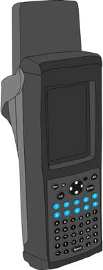
Figure 2-2. Radix FW900 handheld
Radix specifications
• Windows CE operating system
• .NET Framework 4.2
• 400 MHz Intel XScale PXA255
• 128 MB RAM; 128 MB Flash
• 3.5” *89mm) 240 x 320 TFT 65K Color industrial grade touch screen
• 48-key ergonomic keypad with separate numeric keys
• User replaceable lithium-ion battery pack, 3 hour charge, up to 8 hours use
• EnergyAxis PC card
• Elster software
• RF Transmitter - 900 MHz
• RF Receiver - 900 MHz
• FCC compliance: Part 90 and Part 15. The FCC ID is G8JHHI03.
• Operating temperature: -4 °F to +140 °F (-20 °C to + 60 °C)
• USB, Ethernet, serial, IPP, multiple communications ports
• IP-67 rated (1 meter submersion)
• Elster nose cone is IP-67 rated (1 meter submersion)
• MIL-STD-810F method - 1.5 meter drop onto concrete test
The evoWalk and PI 900 handhelds do not support using an external antenna.
Safe RF exposure using external antenna
The antenna used for the evoWalk and PI 900 transmitter must be installed to provide a
separation distance of at least 8 inches (20 cm) from all persons and must not be co-
located or operating in conjunction with any other antenna or transmitter.
More about Radix
For more information on the Radix handheld and its cradle, please refer to the
Radix
FW900 User's Guide
shipped with your handheld.

Elster Handhelds
User Guide 16 2. About handheld devices
Basic operation
The handheld device is pre-loaded with Elster software which allows for either automatic
or manual meter reading functions, or both. The routes are loaded into the handheld using
Route Manager software. Once the interrogator establishes two-way communications
with an Elster RTM, the following data can be collected from various electronic indexes in
the RTM through the use of commands:
Data collected by the handheld device is validated, audited and stored for subsequent
uploading to Route Manager. Meter reading instructions are downloaded to interrogators
indicating what data is required from each RTM in the route. Changes to reading
instructions are made in Route Manager or in the CIS system to ensure that whatever
specific information is needed gets collected. Not all data is requested from all RTMs
making route read-times as low as possible.
Transmission accuracy
The accuracy of transmitted data is insured in two ways:
• the RTM only replies after detection of its unique serial number
• the RTM transmits an error-detection code with the meter data that is used by the
interrogator to confirm that the data has been received without errors.
Within the handheld device are programmable Trouble Codes and a free-form text
message field for specific account details.
Navigating
Simple menu commands allow access to the software functions. These commands fall into
either Route functions or Route Manager Communications functions. From the Route
Selection function a user can specify which of the loaded routes are targeted for reading
operations. Route Manager Communications provides for downloading route
information and uploading read data from the handheld device to the Route Manager
software.
Once the route is loaded, readings can be done automatically over RF, over RF with
verification against the manual meter reading input, or via manual reading input.
Accelerator keys are provided, along with on-demand help, to provide advanced account
and route navigation. See Appendix A, “Accelerator keys for meter reading” and Appendix
B, “Accelerator keys for installing RTMs” for details.
Data collected TRACE handhelds evoWalk
Current meter reading Yes Yes
Daily meter readings (35 days)a
a. Addressable readings often used for billing customer move in/move out.
Any, All, or None All
TOU indexesb
b. Used for billing-rate structure or to encourage conservation.
Up to 4 No
Water leakage Yesc
c. With programmable thresholds.
Yes
Tamper and other alarms Yes Yes

Elster Handhelds
User Guide 17 2. About handheld devices
PI 500 installation tool
Recently added functionality allows users to operate the PI 500 as an installation tool for
TRACE RTMs. In this mode the device performs the following actions:
• setting initial index value (to match the existing mechanical index reading)
• setting leak detection parameters (water only)
• programming of the predivider and pressure compensation factor (gas only)
• verifying or updating of the date and time setting
See Chapter 7, “Installing RTMs” for details.
Note: When used as an installation tool, the PI 500 must be used with the short range
antenna to ensure proper communication with the RTM.
With optional hardware, the handheld device can also capture the meter latitude and
longitude values for use by Elster mobile interrogators and other mapping programs.
PI 900 installation tool
The PI 900 is an installation tool for EnergyAxis gas module RTMs. This device performs the
following actions:
• setting initial index value (to match the existing mechanical index reading)
• programming of EnergyAxis gas modules
• verifying or updating of the date and time setting
See Chapter 7, “Installing RTMs” for details.
Database warning
Do not attempt to modify or edit any of the database tables or files outside of the Elster
handheld / Route Manager environment without prior authorization by Elster technical
support personnel. Unauthorized manipulation of these files may void your software
service agreements.
Elster Handhelds
User Guide 18 3. Handheld operation
3 Handheld operation
Commonly used keys
The handheld’s keyboard allows the user to access software functions. Elster handhelds
respond to the keystrokes independent of hardware.
Note: All letters are assumed to be upper case. Function keys <F1> - <F4> are also used.
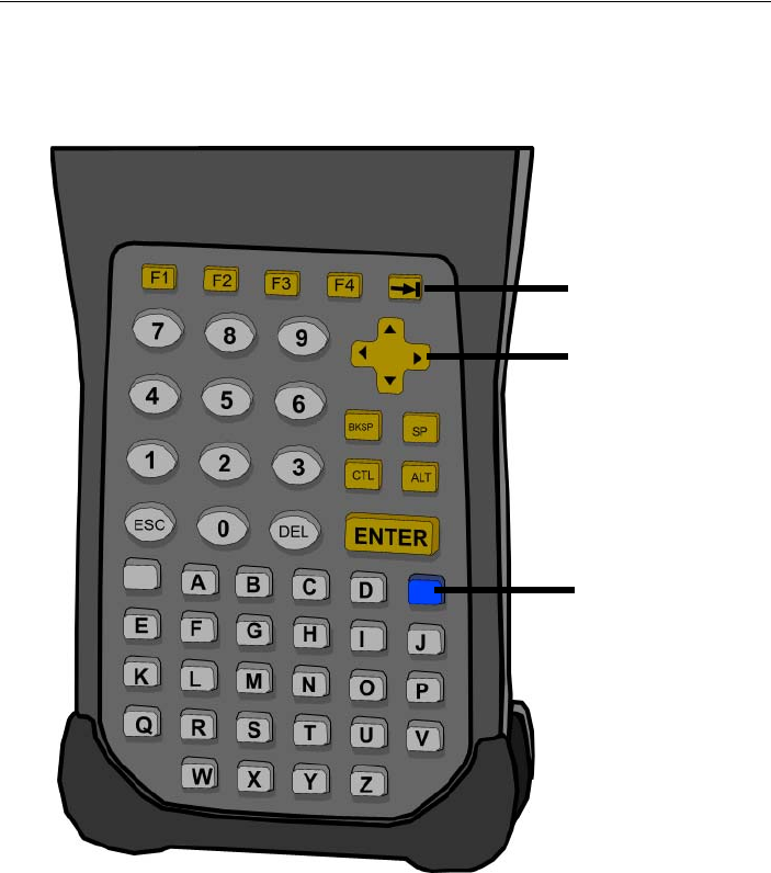
Figure 3-1. Dap CE5240x handheld keyboard
Tab
Arrow keys
Reset and
Function
Elster Handhelds
User Guide 19 3. Handheld operation
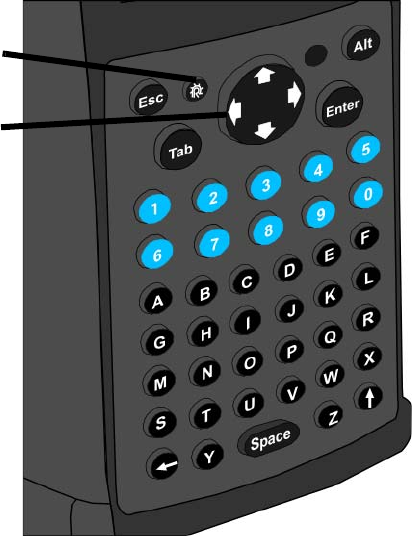
Figure 3-2. Radix handheld keyboard
<Esc>
• Cancels operation
• Exits screen
<Enter>
• In menus/list boxes, selects item
• In editable field, submits entry
• When on an unread RF account, triggers an RF read
• With Automove on and on a completed account, and moves to next account
•In Details list box (History and TOU) initiates single interrogation of highlighted item
Arrow keys
These keys (<Up>, <Down>, <Left>, and <Right>) are used to navigate directionally in the
screen.
<Tab>
• Navigates between fields within the current screen (messages, search, etc.).
Entering responses (Yes/No)
You respond to questions using either of the following methods:
• Tap the button Yes or No with the stylus
• Press <Y> or <N> on the keyboard
• Moving to the desired button by using left/right arrow keys and pressing <Enter>
when the button is highlighted
Radix R button
Arrow keys

Elster Handhelds
User Guide 20 3. Handheld operation
Using the stylus
Use the stylus to tap a command button or to move focus to a data entry field. If you do not
have a stylus, use the tip of your fingernail (not the soft pad of your finger).
Reading meters
Using the handheld device for meter reading is easy. The reading cycle consists of four
main stages:
1. Preparation:
a. Prepare the handheld device to accept the route from the Route Manager
software by touching the F3 - Route Manager Communications line in the main
menu or by pressing <F3>.
b. Once the handheld device is ready to accept a connection, Route Manager can
connect to the handheld device and the route is transferred from Route Manager
to the handheld device.
See Chapter 9, “Communicating with Route Manager.”
2. Initiate meter reading process:
• Begin meter reading by touching the F2 - Route Selection line in the main menu
or by pressing <F2>. The handheld device will display the Route Selection screen
that allows you to select a route for reading.
See Chapter 5, “Reading accounts.”
3. Acquire meter readings:
• If the meter shown on the Read screen has a RTM, then press <Enter> to begin
the read process. The handheld device will interrogate the RTM, report the
reading, and display the next meter in the route. If the meter is manually read,
then enter the numeric meter reading and press <Enter> to move to the next
account.
4. Transfer read data to Route Manager:
• When all readings have been gathered, the handheld device is unloaded by
pressing <Esc> to exit the route and return to the Main Menu. Then press <F3> to
enter Route Manager Communications. After the handheld device connects to
Route Manager, the handheld device will transfer stored readings to Route
Manager on the PC.
See “Uploading routes from device to Route Manager” on page 83.
Turning the device on and off
Dap
To turn the handheld on, press the <F1> key. If the handheld device is not in its charger, it
will normally turn off after three minutes of no activity.
To turn the handheld off, press the Blue key then press the <F1> key.
Radix
To turn the handheld on, press and hold the <Radix R> key until the handheld turns on.
The handheld turns off automatically after the handheld had been idle for more than two
minutes; the idle timeout is configurable (see the
FW900 User Guide
for details).

Elster Handhelds
User Guide 21 3. Handheld operation
Charging the device
Dap
Place the handheld securely in its charging cradle to recharge the battery. The handheld
will automatically turn on once it is placed in the cradle. The Battery Status Light on the
bottom right corner of the handheld will light up indicating a connection has been made:
• red light indicates that the unit is charging
• yellow light indicates that charging is not possible due to various reasons
• green light indicates that the unit is fully charged
Radix
Place the handheld in its cradle to recharge the battery. The red Battery Status Light on
the top right corner of the handheld will flash on and off while the battery is charging. Once
that battery is fully charged, the status light will remain on.
Resetting the handheld device
Dap
You may occasionally need to deliberately reset the handheld. The handheld is a computer
and it can be reset like a desktop computer.
You can reset the handheld device by simultaneously pressing the <F1> + <0> + <9> keys
for several seconds until the handheld beeps.
After the second beep the handheld starts the reboot process.
After the reboot, the Elster PI software will automatically be loaded.
Note: The three keys need to be depressed for a few seconds to start the reset.
Radix
Note: The Radix handheld will not reload the Elster PI software if it is in its cradle when
rebooting using this process.
To reset the handheld:
1. Hold down the <R> + <X> + <↑> keys down simultaneously for several seconds.
2. Release the keys when the screen goes blank.
3. Recalibrate the touch screen as directed.
The Elster PI software will reload if the handheld is not in the cradle.
Logging in to the handheld
If security is enabled for the handheld device, then the meter reader must login before any
routes can be selected. The login information consists of a user name and password.
Different levels of security can be set in Route Manager for each user (refer to the
Route
Manager User Guide
for details).
Elster Handhelds
User Guide 22 3. Handheld operation
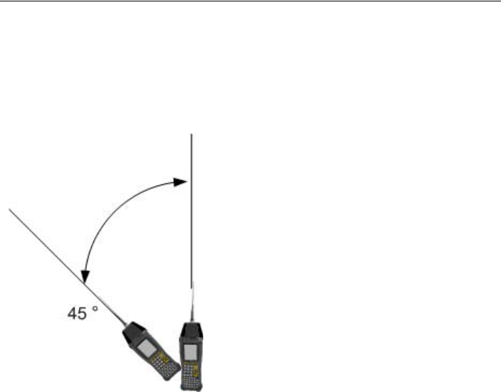
Holding the handheld
For meter reading
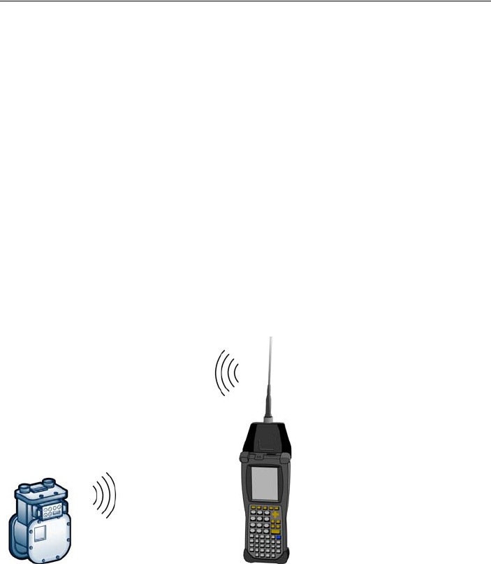
When using a handheld device to read RTMs, hold the handheld device at a distance of at
least 10 feet from the RTM. It should be held between a 45° to 90° angle from the ground
(figure below).
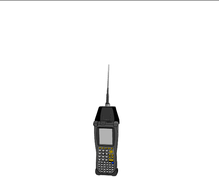
For RTM installation
When programming a RTM, the handheld device uses short range radio frequency. The
handheld device should be held from 0 to 3 feet from the RTM. The angle of the handheld
does not matter. See Chapter 7, “Installing RTMs” for details.
Elster Handhelds
User Guide 23 4. About Interrogator software
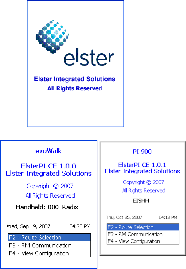
4 About Interrogator software
After successfully logging into the handheld device, you will first see the Interrogator splash
screen followed by the main menu screen.
Elster Handhelds
User Guide 24 4. About Interrogator software
The main menu screen allows the selection of the following modes:
• Route Selection (see “Selecting a route” on page 24)
• Route Manager (RM) Communication (see “RM Communication” on page 24)
• View Configuration (see “Viewing handheld configuration” on page 25)
Selecting a route
To select a route to read:
1. Press <F2> or select Route Selection.
A listing of route Names and Types loaded in the device displays.
2. To select the route for reading touch the desired route on the screen.
— Or —
Use the <Up> and <Down> arrow keys to select the route and press <Enter>.
The first account in the route displays.
See Chapter 5, “Reading accounts” for details.
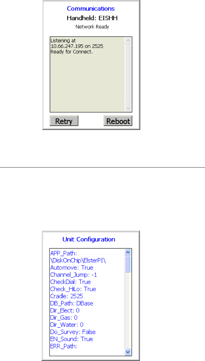
RM Communication
The RM Communication mode is used to exchange data files and other information with
Route Manager. To view the RM Communications screen:
1. Press <F3>.
— Or —
Select <F3> - RM Communication.
The specified communication port opens, the Communications screen displays and
initiates polling for incoming messages from Route Manager.
Elster Handhelds
User Guide 25 4. About Interrogator software
See Chapter 9, “Communicating with Route Manager” for details.
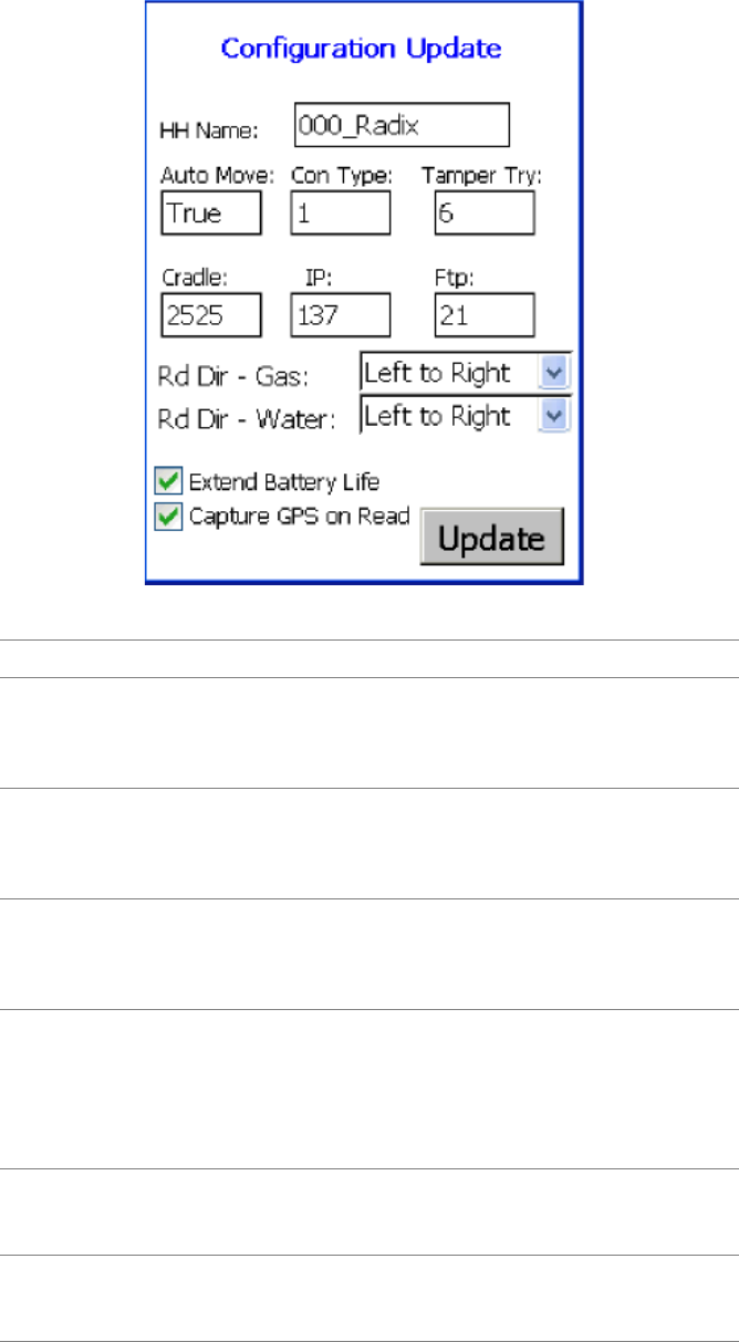
Viewing handheld configuration
To the configuration of the handheld:
1. Press <F4>.
— Or —
Select <F4> - View Configuration to view the configuration settings for the handheld
device.
The View Configuration screen displays the current configuration for the handheld.
Elster Handhelds
User Guide 26 4. About Interrogator software
Updating handheld configuration
Note: The configuration settings should only be modified by the handheld administrator.
1. From the View Configuration screen you can press <F4> again to access the Update
Configuration screen.
The figure below shows the fields available for update.
The table below details the information entered on the Configuration Update screen:
Item Description
HH Name Enter a maximum of 10 characters for the handheld
name.
Note: The entered name must match the handheld
name in Route Manager.
Auto Move Select:
•True - to automatically display the next account’s
screen after a good read
•False - to stay on the account screen after a read
Con Type Set the connection type:
•1 - for Ethernet communication
Note: Contact Elster Customer Support for other types of
communications options.
Tamper Try
[PI 500 only]
Enter a value of 0 to 10 to indicates how many attempts
are made to clear a tamper status.
Note: A higher number will increase battery usage and
reducing the amount of time before the handheld
needs to be recharged. To maximize battery life,
Elster recommends setting this value to 0.
Cradle Port number of the cradle.
Note: Do not change unless directed by Elster Customer
Support.
IP Port number used for IP communications.
Note: Do not change unless directed by Elster Customer
Support.
Elster Handhelds
User Guide 27 4. About Interrogator software
To exit from the Update Configuration screen without making or saving changes,
press <Esc>.
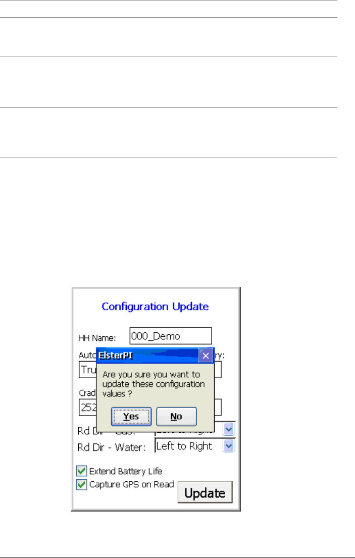
2. After making changes, press Update to save your changes.
A confirmation box will appear to verify that you really want to save your changes.
3. Tap the button Yes or No with the stylus.
— Or —
Press <Y> or <N> on the keyboard.
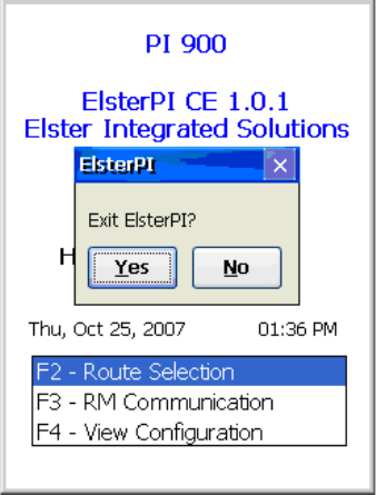
Exiting Elster Interrogator
1. While the main menu screen is open, press <Esc> to exit the software.
A dialog displays asking you to confirm you wish to exit.
Ftp Port number used to FTP file transfers.
Note: Do not change unless directed by Elster Customer
Support.
Extend Battery Life
[PI 500 only]
If checked, the RF communications port will be closed
after each read to maximize battery life.
If unchecked, the communications port remains open
between reads allowing faster reads.
Capture GPS on Read
[PI 500 and evoWalk]
If checked and the account GPS coordinates are 0, the
meter reader will be asked if they want to capture the
RTM GPS coordinates. See “Taking GPS coordinates” on
page 67 for details.
Item Description
Elster Handhelds
User Guide 28 4. About Interrogator software
2. Use <Tab>, <Left> or <Right> arrow keys to select the response.
— Or —
Touch Yes or press <Y> or press <Enter> when the button is highlighted to accept the
selection.
Touch No or press <N> or press <Enter> when the button is highlighted to cancel.

Elster Handhelds
User Guide 29 5. Reading accounts
5 Reading accounts
Navigating accounts
You can use the handheld's keyboard or the touch screen using a stylus to execute
functions. The handheld responds to the keystrokes independent of platform. All letters are
assumed to be upper case. Function keys <F1> - <F4> are also used.
<Esc>
• Cancels an operation
• Closes the current screen
<Enter>
• In menus/list boxes selects item
• In editable field submits entry
• With Automove on, submits entry and moves to next Account
• In Details list box (History & TOU) initiates single interrogation of highlighted item
• In Read box on Data Entry Screen, initiates RF interrogation of current account
<Up> and <Down> arrow keys
These keys are used to navigate between accounts within the current Route. When either
the first or last account is reached an audible warning will sound and the display will
remain on the current account.
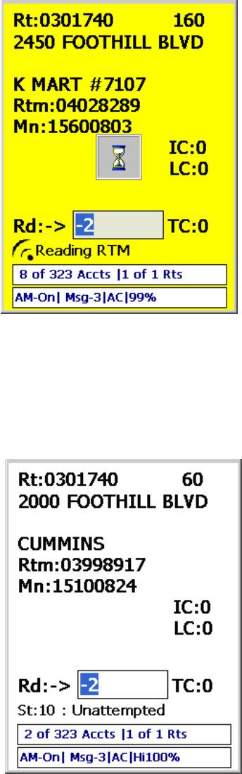
Reading an account
After selecting a route (see “Selecting a route” on page 24), you will see the first account in
the route.
If there are appointments set for selected route, the message, “Do you want to view the
appoints for this route?”, will display on the screen (see “Viewing appointments” on page
50).
Note: The appearance of the handheld display is configurable. Refer to the
Route
Manager User Guide
for details. Your handheld display may appear different
from examples shown in this manual.
Elster Handhelds
User Guide 30 5. Reading accounts
The Read screen appears as below.
Index reads can be entered in either of the following ways:
• manually (see “Performing a manual index reading” on page 31)
• as part of a single or multiple parameter RF read (see “Performing a default read of
an unread account” on page 30)
• as part of a multiple parameter read of Index, History, and TOU:
•“Performing a multiple parameter RF read” on page 36
•“Performing a single history/TOU RF read” on page 39
•“Performing a general index RF read” on page 39
Note: History and TOU reads can be performed either singly or as part of a multiple
parameter read of Index, History and TOU.
From this screen you can perform the following tasks:
•“Adding a trouble code” on page 33
•“Adding a skip code” on page 33
•“Entering messages for an account” on page 34
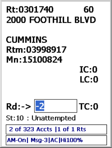
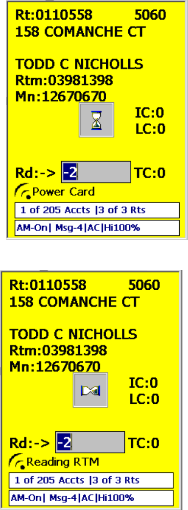
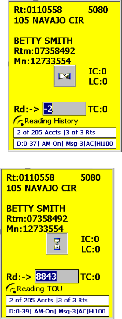
Performing a default read of an unread account
To trigger a single or multiple parameter RF read of the RTM:
• If the current read value is -2 and the RTM number is not blank, press <Enter>.
The handheld will read the current meter (index), as well as any requested History or
TOU VRT reads.
RF interrogation starts and the status displays as
Reading RTM
and the background
of the display changes color.
Rt: Route ID Account Sequence No.: 1
Address line 1: first 20 characters
Address line 2:remaining 20 characters
Customer Name: first 20 characters of the customer’s name
Rtm: RTM Serial Number
Mn: Meter Number LC: Location Code
IC: Instruction Code
Rd: Index Read –>: Direction of
Data Entry
TC: Trouble Code
St: Account Status
D:0-35 Number of VRT details (requests)
available
AM-off/on AutoMove enabled
Msg-2 There are 2 messages in the
alarm category.
AC or BT: the source of power for
the handheld:
•AC from cradle
• BT from battery
Hi100% : shows that the battery is
charged at 100%
Elster Handhelds
User Guide 31 5. Reading accounts
If Enable sound is enabled, a sound will notify you of the status of the reading
(success or fail).
If Automove is enabled and the reading was successful, the display shows the next
account in the route. If the account just read is the last one in the current route an
audible alert will sound.
Once the interrogation is completed the account record will be updated.
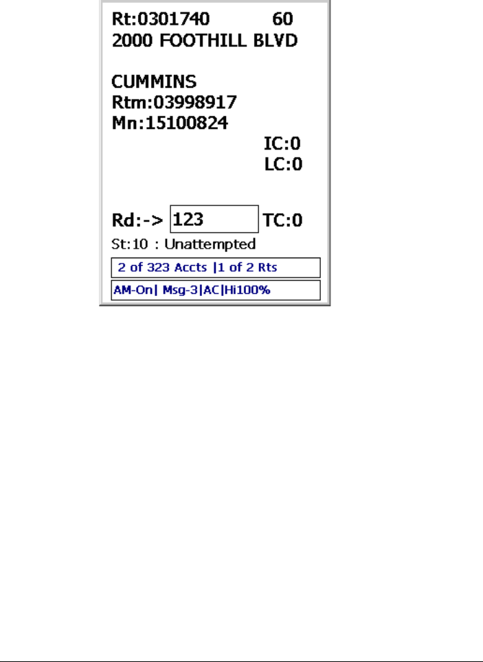
Performing a manual index reading
To perform a manual index read:
1. In the Rd: text box, enter digits (from 0 to 9) for the meter reading.
2. Press <Enter>.
The direction of manually reading a meter is shown by the arrow (-> or <-) by the
reading and is dependant on the read direction setting for the meter type.
Note: Reads may be entered from left to right or from right to left.
Elster Handhelds
User Guide 32 5. Reading accounts
The number entered will be checked against:
• The number of dials as reported in Route Manager for the account.
This option can be turned off/on in Route Manager.
• Upper Limit and Lower Limit for the account as reported in Route Manager.
This option can be turned off/on in Route Manager.
• Previous read for the account as reported in Route Manager.
A zero (0) uploaded for the value to check turns this option off.
If the entered index read fails the verification above a message displays asking if it
should be recorded or cancelled.
3. Choose the option by selecting OK to record or press <X> to cancel.
Moving on to the next account
If the Automove option is enabled, a successful read will cause the display to automatically
move to the next account in the route. When either the first or last account is reached an
audible warning will sound and the display will remain on the current account.
Additional account reading options
The following accelerator keys can be used from the Read screen as part of the meter
reading process.
Clearing index read
Accelerator key: <C>
Pressing <X> has no effect.
After pressing <C>, the reading is cleared and the cursor is positioned in the index read
field waiting for the entry to overwrite the previous reading.
Forcing unattempted account
Accelerator key: <F>
Pressing <X> has no effect.
Elster Handhelds
User Guide 33 5. Reading accounts
If the account had a manual reading, then after pressing <F>, a message dialog displays
asking you if you wish to reset the account:
• Selecting Yes clears the reading and trouble code and sets the account status to
Unattempted.
• Selecting No has no affect on the account.
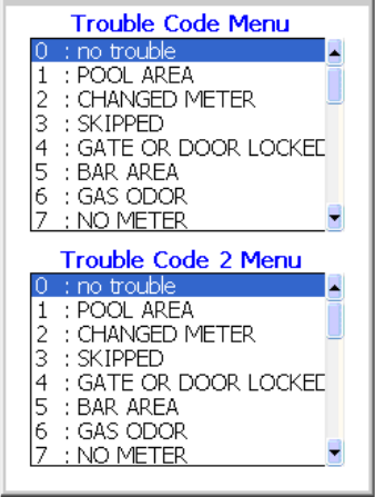
Adding a trouble code
Accelerator key: <T>
Pressing <X> has no effect.
Trouble codes are used to indicate problems with obtaining readings. A trouble code
should be entered with a reading. You can enter up to two trouble codes for a reading.
1. While in the Read screen, press <T> to move the cursor to the Trouble Code field.
2. Enter a one or two digit trouble code.
3. To review the list of available trouble codes, press <T> again to display the Trouble
Codes List screen.
4. Use the <Up> and <Down> arrow keys to select the desired trouble code from the
list.
5. If needed, enter a second trouble code by tapping to select the desired trouble code
from the Trouble Code 2 Menu.
6. Press <Enter> to update the account with the selected trouble code.
— Or —
Press <Esc> to close the window without entering a trouble code.
Note: The stylus can be used to select the desired Trouble Code from the list. This action
updates the account with the selected Trouble Code and closes the window.
Adding a skip code
Accelerator key: <S>
Pressing <X> has no effect.

Elster Handhelds
User Guide 34 5. Reading accounts
Skip codes are used to indicate a reason why an account could not be read. A skip code
should be entered when a reading cannot be obtained.
1. While in the Read screen, press <S> to display the Skip Code list.
2. Use the <Up> and <Down> arrow keys to select the desired skip code from the list.
3. Press <Enter> to update the account with the selected skip code.
— Or —
Press <Esc> to close the window without entering a skip code.
Note: The stylus can be used to select the desired Skip Code from the list. This action
updates the account with the selected Skip Code and closes the window.
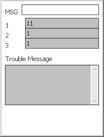
Entering messages for an account
Accelerator key: <M>
Pressing <X> has no effect.
Note: Messages can be allowed or disallowed for editing in the Device configuration in
Route Manager.
Route Manager can be configured to sound an alarm if the message contains an alarm. If
sound is disabled a message box will pop up with the warning. See the
Route Manager
User Guide
for details.
To view or enter a message regarding an account:
1. While in the Account screen, press <M> to open the Messages screen.
2. Press <Tab> or select a message field with the stylus to move the cursor to the
message for editing.
3. Enter text in either of the following:
• a 19-character message (MSG)
• up to three 20-character user messages (1, 2, and 3)
These messages can be sent from Route Manager. If M appears in the lower
Information bar of the data entry display, the account contains one or more
messages. If !! follows the message then one of the messages contains an
alarm.
• a Trouble Message
This is an 80-character message used to specify trouble conditions when no utility
Elster Handhelds
User Guide 35 5. Reading accounts
trouble code applies.
4. Press <Esc> to close the Message screen.
A message dialog displays asking if you want to save changes to messages.
5. Press Yes or <Y> to save the changes and close the screen.
— Or —
Press No or <N> to close the screen without saving changes to messages.
Setting the resequence flag
Accelerator key: <Q>
Pressing <X> has no effect.
If a route’s accounts are out of sequence, setting the Resequence flag marks the route for
resequencing by date time stamp during reading the route. The resequencing is done in
the Billing system after uploading the route to Route Manager.
1. With an account in the route displayed, press <Q>.
A dialog displays asking you to confirm the resequence.
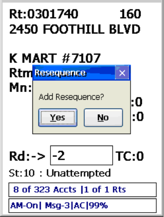
Elster Handhelds
User Guide 36 5. Reading accounts
The message box will pop-up to verify if resequencing is desired.
2. Select either Yes or No by:
• Touching Yes or No.
• Pressing <Y> or <N> on the keyboard.
• Moving to the desired button by using <Left> or <Right> arrow keys to select the
response and press <Enter>.
Removing a resequence flag
To remove a resequence flag from a route:
1. With an account in the route displayed, press <Q>.
A dialog displays asking you to confirm the resequence.
2. Select No or press <N>.
Performing a multiple parameter RF read
Accelerator key: <R>
Pressing <X> has no effect.
Use the multiple parameter RF read to get the index read and all the VRT requests.
1. With an account in the route displayed, press <R>.
— Or —
Press <Enter> on an unread account.
RF interrogation starts and the status displays as
Reading RTM
,
Reading History
and
Reading TOU
and the background of the display changes color.
Elster Handhelds
User Guide 37 5. Reading accounts
Elster Handhelds
User Guide 38 5. Reading accounts
If Enable sound is enabled, a sound will notify you of the status of the reading
(success or fail).
If Automove is enabled and the reading was successful, the display shows the next
account in the route. If the account just read is the last one in the current route an
audible alert will sound.
Once the interrogation is completed the account record will be updated.
Elster Handhelds
User Guide 39 5. Reading accounts
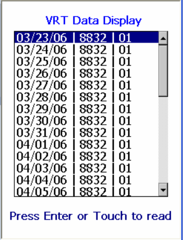
Performing a single history/TOU RF read
If a
D
appears in the lower left corner of the data entry display, the account contains one or
more History and or TOU requests.
1. To retrieve the history or TOU request, press <D> to display a pop-up list of all
requests.
2. Use the Up / Down arrow keys or a stylus to select the History/TOU request to read.
3. Press <Enter> to start the interrogation.
An RF communications window will open and RF interrogation will start. The user will
be able to watch commands issued and replies returned from the target RTM.
The list will be updated with the information obtained from the RTM for the chosen
VRT request.
If a valid index read does not exist, one will be added to any single History requests.
A new index read will be added to any Single TOU request.
Once the interrogation is completed the account record will be updated.
4. Press <Esc> to close the screen.
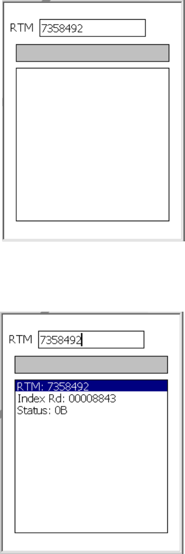
Performing a general index RF read
Accelerator key: <G>
Pressing <X> has no effect.
Use a general index RF read to obtain an “on the fly” read of an RTM.
Note: The results of a general index read are
not
returned to Route Manager.
1. With an account in the route displayed, press <G>.
A popup display opens.
Elster Handhelds
User Guide 40 5. Reading accounts
2. Enter the desired RTM number and press <Enter>.
An RF communications window will open and RF interrogation will start. You can
watch commands issued and replies returned from the target RTM.
When the interrogation is completed, the communications commands will be
replaced with read results.
Note: Data is NOT added to the database.

Elster Handhelds
User Guide 41 5. Reading accounts
Jumps
Jumps are moving from the current account in the current route to various other accounts
and routes.
Viewing Account Details screen
Accelerator key: <A>
Press <A> to trigger a jump to the Account Details screen of the selected account on the
data entry screen.
Pressing <X> has no effect.
Press <Esc> to close Account Details screen.
Jumping to the beginning of current route
Accelerator key: <B>
Press <B> to trigger a jump to the first account in the current route.
Press <X> to return to the screen displayed prior to the jump.
If you press <B> at the beginning of the route a beep sounds and the display remains on
the current account.
Jumping to the end of current route
Accelerator key: <E>
Press <E> to jump to the last account in the current route.
Press <X> to return to the screen displayed prior to the jump.
If you press <E> at the end of the route a beep sounds and the display remains on the
current account.
Jumping to a specified sequence number
Accelerator key: <J>
1. Press <J> to jump to a specified sequence number in the current route.
2. After pressing the J hot key an entry window will pop up.
3. Type the sequence number in the box and
4. Press <Enter>.
Press <X> to return to the screen displayed prior to the jump.
Jumping to the next route
Accelerator key: <N>
Press <N> to jump to the next route.
Pressing <X> has no effect.
If you press <N> on the last route a beep sounds and the display remains on the current
account.
Jumping to the previous route
Accelerator key: <P>
Press <P> to jump to the first account in the previous route.
Pressing <X> has no effect.
Elster Handhelds
User Guide 42 5. Reading accounts
If you press <P> on the first route a beep sounds and the display remains on the current
account.
Jumping to next unread account in the current route
Accelerator key: <U>
Press <U> to jump to the next account with a index read of -2 and trouble code 0 in the
current route.
Press <X> to return to the screen displayed prior to the jump.
Searching the current route
Searches allow you to jump to any specified account in the current route. The following
searches are available:
• Account number
•RTM number
• Meter number
• Customer (name)
•(Customer) Address
• Premise code
• Specific trouble code
• Any trouble code
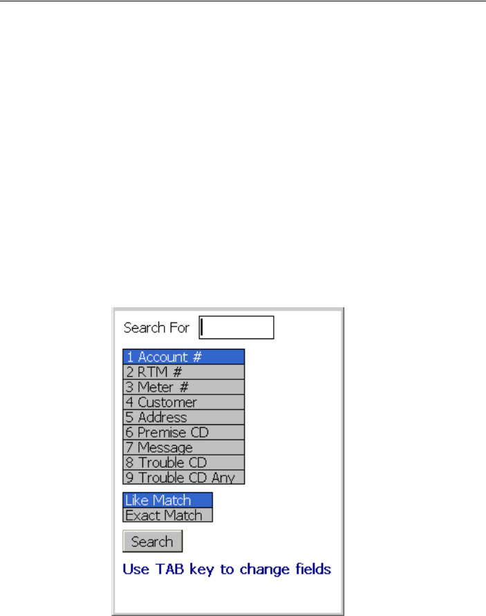
Performing a search
1. Press <H> to display the search type dialog.
2. Use the <Up> and <Down> arrow keys or the stylus to select the type of search.
— Or —
Press <Tab> or use the stylus to select fields on the screen.
3. Select whether Exact Match is wanted or the search performed by partially
submitted information, Like Match, is preferred (except for search for accounts with
trouble code).
Elster Handhelds
User Guide 43 5. Reading accounts
4. Enter the Search For text string.
5. Click Search to begin the defined search
— Or —
Press <Enter> while the Search button is highlighted.
6. Press <Esc> to cancel the search.
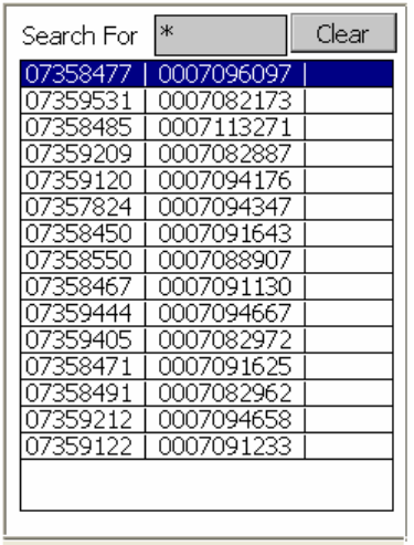
Searches with only one account returned will jump directly to that account.
If the search results in multiple accounts, the results list will present the list of
accounts:
7. To jump to an account, select an item from the results list and press <Enter>.
Or
Select the account by tapping with the stylus.
8. Press <Clear> to clear the search and to start over.
9. Press <X> to return to the account displayed prior to pressing <H>.
Note: RTM number for exact search has to be 8 digits.
Example Search - Address
To search for all addresses that begin with "3102 DEWAR":
1. Enter 3102 DEWAR in the Search For string.
2. Select 5 Address.
3. Click Like Match.
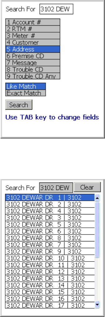
Elster Handhelds
User Guide 44 5. Reading accounts
4. Click Search.
If multiple accounts are found, they are displayed as Address followed by first part of
address.
5. Select the account to view the account’s screen.
6. Press <H> to return to the search results screen.
— Or —
Click Clear to return to the search screen to start a new search.
Example Search - Customer
To search for all Customers named "Smith":
1. Enter Smith in the Search For string.
2. Select 4 Customer.
3. Click Like Match.
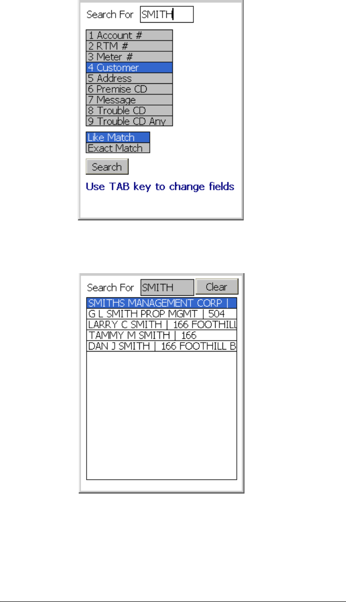
Elster Handhelds
User Guide 45 5. Reading accounts
4. Click Search.
Multiple accounts show Customer name and first part of the Address.
5. Select an account to view the account’s screen.
6. If that account is not correct, press <H> to return to the search results screen.
— Or —
Click Clear to return to the search screen to start a new search.
Viewing additional information
The Account Data Entry screen provides access to several information screens. Most of
these take the form of a dialog.
Press <Esc> to close the information screen and return to the Account Data Entry screen.
Elster Handhelds
User Guide 46 5. Reading accounts
Viewing Help and available commands
Accelerator key: <F1>
Pressing <X> has no effect.
To display the information:
• Use the <Up> and <Down> arrow keys to select the desired accelerator key from the
list and press <Enter>.
• Click the desired function with the stylus.
• Press the shortcut letter on the keyboard.
• Press <Esc> to close the dialog.
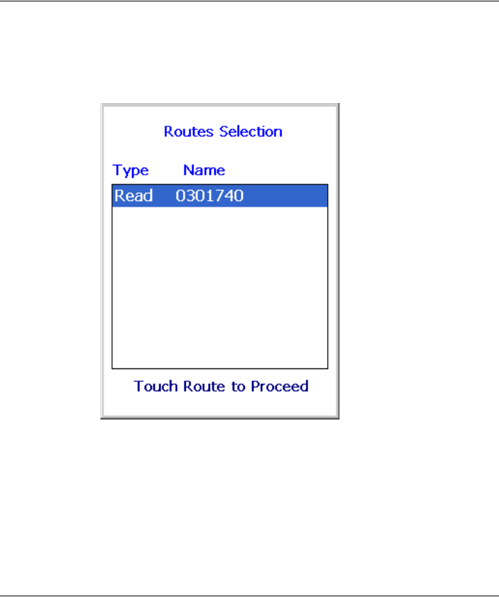
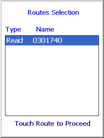
Viewing Routes Selection screen
Accelerator key: <F2>
Pressing <X> has no effect.
The Routes Selection screen allows you to select a route to be processed.
To select a route from a list:
1. Press <F2> to view the Routes Selection screen.
2. Use the <Up> and <Down> arrow keys to select the desired route.
3. Press <Enter> to view the first account in the selected route.
Note: Clicking the desired route with a stylus jumps to the first account in the selected
route
4. Press <Esc> to close the dialog.
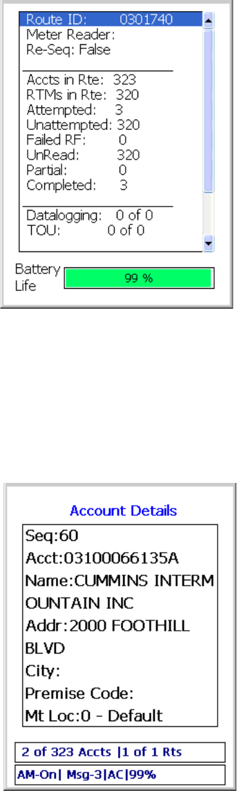
Viewing Route Summary screen
Accelerator key: <F3>
Pressing <X> has no effect.
The Route Summary screen shows battery life (%) as well as statistics collected from the
route.
1. Press <F3>.
Elster Handhelds
User Guide 47 5. Reading accounts
A list of routes displays.
2. Use the <Up> and <Down> arrow keys to select the desired route.
3. Press <Enter>.
A dialog displays the Route Summary screen.
4. Press <Esc> to close the dialog.
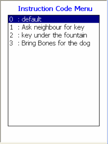
Viewing Account Details screen
Accelerator key: <A>
The Account Details screen displays additional information about the account.
1. Press <A> to display the account details of a selected account on the data entry
screen.
2. Press <Esc> to close the dialog.
Elster Handhelds
User Guide 48 5. Reading accounts
Viewing Instruction Code screen
Accelerator key: <I>
Instruction codes are used to indicate instructions for Meter Reader.
1. Press <I> to view the list of available instruction codes.
2. Press <Esc> to close the dialog.
Viewing Location Code screen
Accelerator key: <L>
Location codes are used to indicate the location of meters and RTMs.
1. Press <L> to view the list of available location codes.
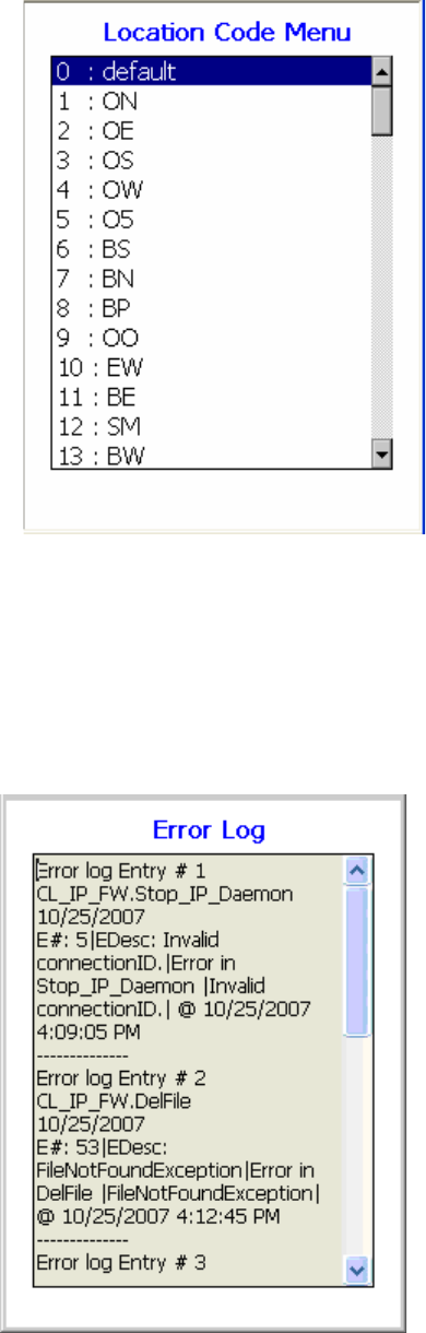
Elster Handhelds
User Guide 49 5. Reading accounts
2. Press <Esc> to close the dialog.
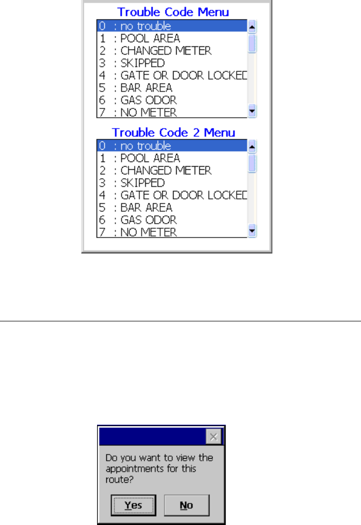
Viewing Error Log screen
Accelerator key: <O>
1. Press <O> to view the Error Log screen.
2. Use the <Up> and <Down> arrow keys to move within the screen.
3. Press <Esc> to close the dialog.
Elster Handhelds
User Guide 50 5. Reading accounts
Viewing Trouble Code screen
Accelerator key: <T>
Trouble codes are used to indicate problems with obtaining readings.
1. Press <T> to view the list of available trouble codes.
2. Use the <Up> and <Down> arrow keys to move within the list.
3. To enter a Trouble Code 2, tap the screen with the stylus then use the <Up> and
<Down> arrow keys to move within the list.
4. Press <Esc> to close the dialog.
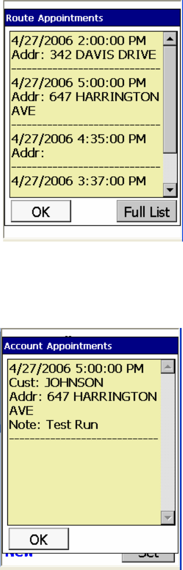
Viewing appointments
Route Manager allows you to set appointments for an account.
To view appointments for a selected account:
1. From the Routes Selection screen, select a route.
2. If there are appointments set for selected route, the message, “Do you want to view
the appointments for this route?”, will display on the screen.
3. Click on Yes to view the list of current appointments for the selected route.
After clicking on Yes to view the list of appointments, a brief list will display all
appointments set for selected route.
Elster Handhelds
User Guide 51 5. Reading accounts
Note: Only appointments whose date is greater than or equal to the current date will be
displayed.
4. To view the appointment details, click Full List.
The appointment date/time, customer name, service address, and note will be
displayed.
The full appointment screen will also be displayed just prior to moving to the account
on the route for which the appointment was made.
5. Click OK to close the Appointments screen.

Elster Handhelds
User Guide 52 6. Using the VersaProbe
6 Using the VersaProbe
The VersaProbe device is a universal probe for remote reading of water meters equipped
with a remote register and touchpad. With a true open-architecture design, it allows the
utility to read any brand touchpad meter in the system with a single probe, eliminating the
need for multiple sets of reading equipment.
The VersaProbe can be used as a standalone device (disconnected mode) or attached to a
handheld device (connected mode). When used as a standalone device, the VersaProbe
will store reads until it is attached to the handheld device at a later time. The reads are
then unloaded and attached to the correct accounts in the route.
Configuring a VersaProbe connection
The VersaProbe can communicate to the handheld device using either a serial or
Bluetooth connection. All communications use the Sensus I/O mode.
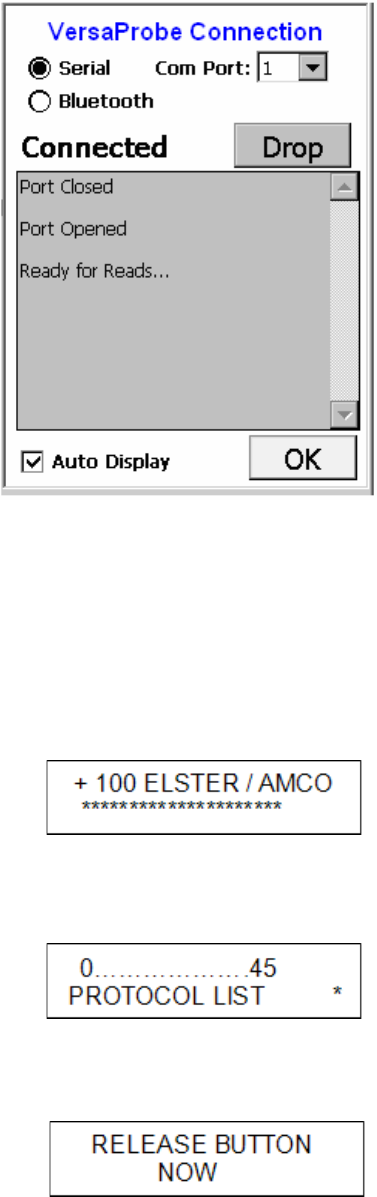
Serial communication mode
To communicate in serial mode:
1. For the PI 500 handheld, connect the lemo end of the lemo cable to the Dap
handheld’s lemo port and the other end of the cable to the 6-pin connector of the
VersaProbe.
For the evoWalk handheld, connect the 11-pin mini DIN end of the cable to the Radix
handheld’s Port A and the other end of the cable to the 6-pin connector of the
VersaProbe.
2. Press <V> to view the VersaProbe Connection screen.
3. Ensure that Serial is selected and that the Com Port is Com1.
4. Check Auto Display to automatically display the VersaProbe Connection screen.
If Auto Display is not checked, press <V> at the main menu screen or Meter
Readings screen to view the VersaProbe Connection screen.
5. Click Connect.
Once the connection is established, the Connect button changes to Drop.
Elster Handhelds
User Guide 53 6. Using the VersaProbe
6. Click Drop to cancel the connection.
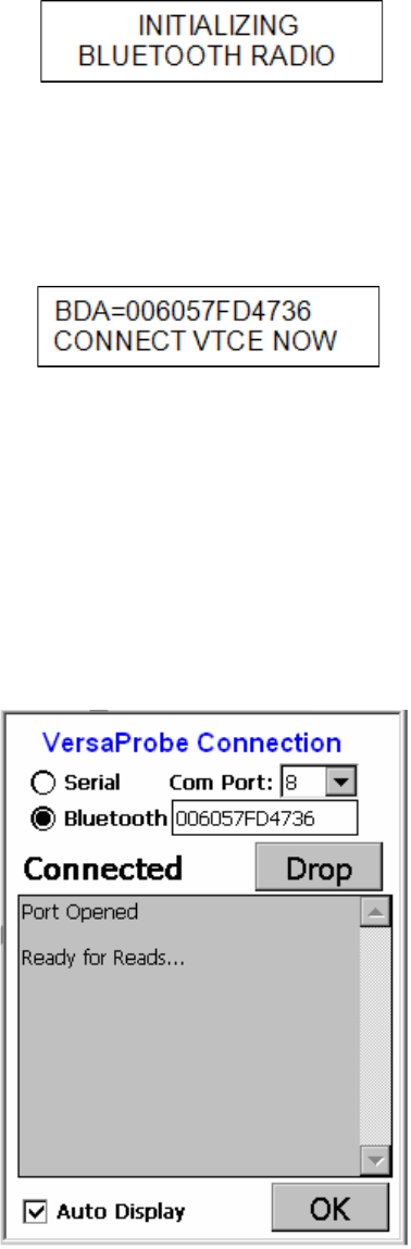
Bluetooth communication mode
To activate the Bluetooth radio:
1. Press and hold the trigger button for about 12 seconds.
During this time the display will progress through several steps.
Initially asterisks begin to appear on the display, from left to right.
2. As you continue to hold the trigger button, a blinking * will appear in the right corner
of the protocol list display to indicate that Bluetooth radio is installed.
3. Continue holding the trigger button, until the display indicates you can release the
button.
4. Release the trigger button.
The Bluetooth radio initializes.
Elster Handhelds
User Guide 54 6. Using the VersaProbe
The VersaProbe will perform a short radio module test and then display its Bluetooth
device address (BDA) also known as the Bluetooth ID.
5. Enter the Bluetooth ID into the handheld by updating the handheld’s configuration
properties using Route Manager.
See Chapter 9, “Communicating with Route Manager” for details.
6. On the handheld, press <V> to view the VersaProbe Connection screen.
7. Ensure that Bluetooth is selected and that the Com Port is correct:
• For the PI 500 handheld the Com Port is 8.
• For the evoWalk handheld the Com Port is 6.
8. Check Auto Display to automatically display the VersaProbe Connection screen.
If Auto Display is not checked, press <V> at the main menu screen or Meter
Readings screen to view the VersaProbe Connection screen.
9. Click Connect.
Once the connection is established, the Connect button changes to Drop.
10.Click Drop to cancel the connection.
Elster Handhelds
User Guide 55 6. Using the VersaProbe
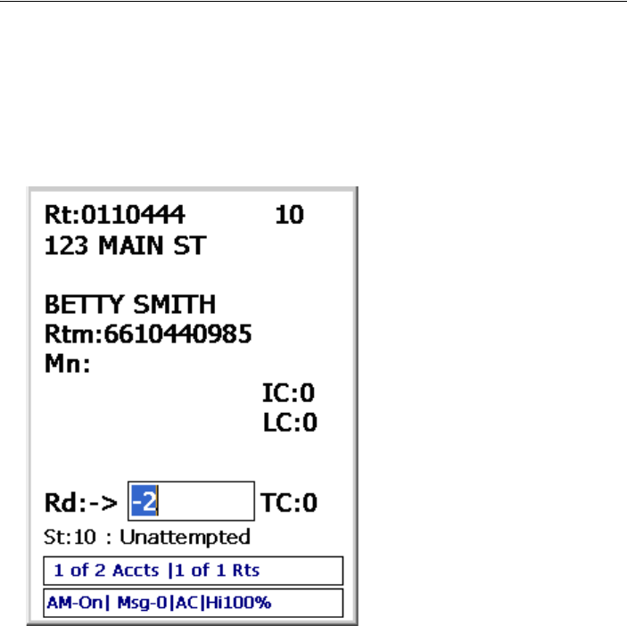
Reading using a VersaProbe
In order to read an account with a VersaProbe, the account must be configured with the
Probe Encoder Number of the VersaProbe. On the handheld, the RTM field shows the
encoder number to be used by the VersaProbe.
Note: The probe encoder number must be 10 digits long.
The VersaProbe can read meters in either the connected or disconnected mode.
Establishing the VersaProbe connection
See “Configuring a VersaProbe connection” on page 52 for details on configuring the
connection.
1. At either the main or data entry screen, press <V> to view the VersaProbe
Connection screen.
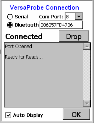
2. Ensure the connection settings are correct and then click Connect.
Once the connection is established, the status changes to
Connected
and the
Ready
for Reads
message displayed.
Rt: Route ID Sequence Number
Address 1
Address 2
Rtm: Probe Encoder Number IC: Instruction Code
Mn: Meter Number LC: Location Code
Rd: Index Read:
• -2 - indicates unread account
• positive number - indicates a reading
–>: Direction of Data Entry
TC: Trouble Code
St: Account Status
Number of Accounts in route Number of Routes in handheld
AM-off/on
AutoMove enabled
Msg-0 There are 0
messages in the
alarm category.
AC or BT : the source of power for
the handheld:
•AC from cradle
• BT from battery
Hi100% : shows the charge level
in the battery i(for example, 100%)
Elster Handhelds
User Guide 56 6. Using the VersaProbe
3. You are ready to read meters using the VersaProbe (see “Reading a meter” on page
56).
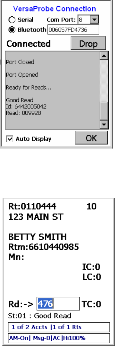
Reading a meter
When the VersaProbe is ready for the reads (see “Establishing the VersaProbe connection”
on page 55):
1. Hold the VersaProbe up to the meter.
2. Press the trigger button and then release it within less than four seconds.
If Enable sound option is enabled, a success or fail sound will alert you with the
result of reading.
Note: If
Auto Display
is checked the handheld will automatically display the VersaProbe
Connection screen to read the meter. If it is not checked, press <V> at the main
menu screen or Meter Readings screen to show the VersaProbe Connection
screen.
Elster Handhelds
User Guide 57 6. Using the VersaProbe
3. Click OK to return to the Meter Readings screen.
You will be returned to the last Account screen you were on, not to the account that
was just updated. However, the read will be updated in the account as shown
below.
• Elster PI software will match the VersaProbe read to the correct account using the
probe encoder number, no matter what route the account is found in.
• If the encoder number is not found in any route, then a mismatch error will be
displayed.
• If the VersaProbe is used in the disconnected mode, then the handheld device will
take each stored reading from the VersaProbe and match it to the correct account
after the VersaProbe is reconnected to the handheld device.
Elster Handhelds
User Guide 58 6. Using the VersaProbe
Note: If you return to the Account screen for the encoder you just read and the read value
is -2, press <Enter> to refresh the screen. The read value is replaced by a positive
number indicating the reading.
Note: If AutoMove is on, press <Enter> again to advance to the next Account screen.
4. When ready to unload the stored reads, connect the VersaProbe to the handheld
device and press the VersaProbe’s trigger to start the unload process.

Elster Handhelds
User Guide 59 7. Installing RTMs
7 Installing RTMs
The PI 500 handheld can be used to install and read RTMs and the PI 900 can be used to
install RTMs. The handheld can perform the following actions:
• program an RTM index
• set special gas and water (PI 500 only) parameters
• verify and set RTM date and time
• capture GPS coordinates
The handheld can also capture additional information associated with meter and index
change outs performed at the time of the RTM installation.
All information is saved on the handheld device and brought back to Route Manager for
review and storage.
Installing RTMs using the PI 500
In order to use the handheld to install RTMs, a route must first be set up in Route Manager
with a Route Type = Install. This route will contain the meter number, customer name,
service address and other account information. Typically this route is imported from a CIS
system where the route is being used as a manual read route.
Appointments can be assigned to accounts in the Install route from Route Manager.
After the route is downloaded to the handheld device you can select the route from the
handheld device Route Select screen. The selected route should have a type of Install.
After moving to an account in the route, you can do one of the following:
• a meter change out followed by a RTM install (see “Changing out a meter” on page
60)
• an index change out followed by a RTM install (see “Changing out an index” on page
61)
• a RTM install without a meter or index change out (see “Installing an RTM” on page
62)
The RTM installation is done at low power so that the meter installer can stand close to the
RTM. The handheld can be held from 0 to 3 feet from the RTM.
After the installation is finished, the GPS coordinates of the meter are captured before the
handheld moves to the next account. Once all accounts are complete, the route can be
uploaded into Route Manager.
Changing out meters and indexes
Note: The appearance of the handheld display is configurable. Refer to the
Route
Manager User Guide
for details. Your handheld display may appear different
from examples shown in this manual.
1. From the RTM installation screen, press <F4> to view the Change Out screen.
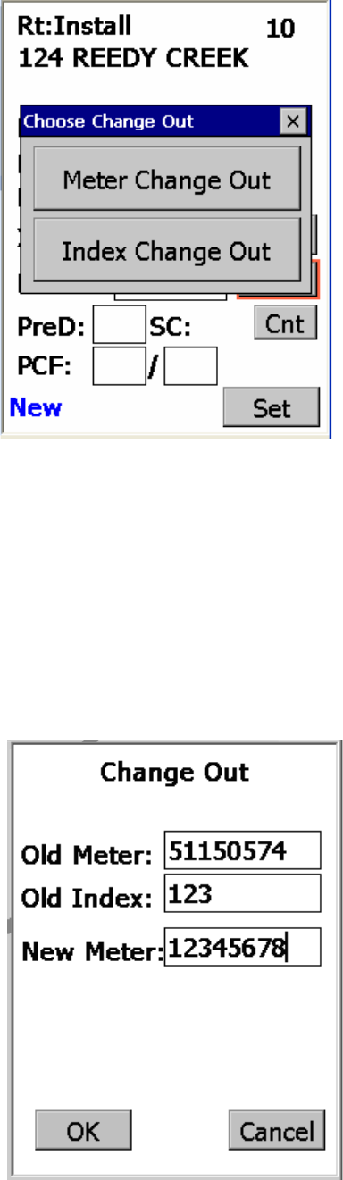
Elster Handhelds
User Guide 60 7. Installing RTMs
2. Choose either Meter Change Out or Index Change Out.
The Change Out screen displays:
•“Changing out a meter” on page 60
•“Changing out an index” on page 61
Changing out a meter
1. If you selected Meter Change Out, enter the Old Index.
2. Enter the New Meter number.
The PI 500 will display the Old Meter number for the account.
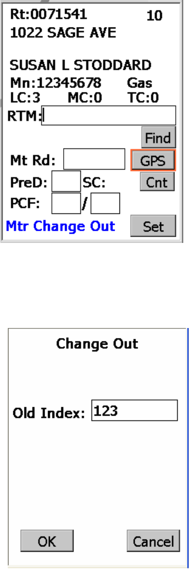
Elster Handhelds
User Guide 61 7. Installing RTMs
3. Click OK when finished.
After a successful change out, the installation screen displays the status
Meter
Change Out
.
Changing out an index
1. If you selected Index Change Out, enter the Old Index.
2. Enter the reading from the Old Index that you plan to change out.
3. Click OK when you are finished.
After a successful change out the installation screen displays the status
Idx Change
Out
.
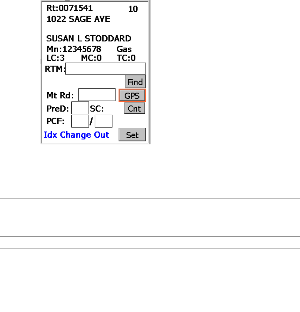
Elster Handhelds
User Guide 62 7. Installing RTMs
Installing an RTM
The RTM installation screen and process will vary slightly depending on whether the meter
is a gas or water meter, and the generation of the RTM. The table below details the
specifics of each RTM generation.
The screens for Gen 5 gas and water installation are shown below.
RTM
Generation Meter Type RTM Serial Number FCC ID Programming Notes
2.0 Water, Gas < 2500000 G8J3GNAMR8 Programming Stick
2.5 Water (pit) ≥ 2500000 ≤ 6500000 G8JPIT25 magnet
2.5 Water (remote) ≥ 2500000 ≤ 6500000 G8JGEN25 Programming Stick
3.x Water (remote) ≥ 2500000 ≤ 6500000 G8JGEN03 magnet
Gas (remote) ≥ 2500000 ≤ 6500000 G8JGEN03 jumper
5.0 Gas (direct) > 6500000 G8JVRT01
Water (remote, integral) > 6500000 G8JVRT02
Water (pit) > 6500000 G8JVRT03
Gas (standalone) > 6500000 G8JVRT04
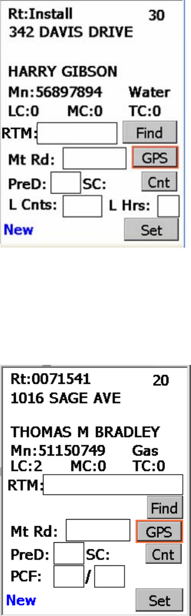
Elster Handhelds
User Guide 63 7. Installing RTMs
Water meter RTM installation display
Gas meter RTM installation display
Rt: Route ID
Mn: Meter Number Meter type: Water
LC: Location Code
MT: Meter Type MC: Meter Location Code TC: Trouble
Code
Rtm: RTM Serial Number Find: Used to find the RTM Serial
Number
Mt Rd: Index Read GPS: It will show GPS screen
PreD: PreDivider SC: Subcounts Cnt: Used to read Subcounts
L Cnts: Leak Counts L Hrs: Leak Hours
Set: To set entered parameter
values
Rt: Route ID
Mn: Meter Number Meter type: Gas
LC: Location Code MC: Meter Location Code TC: Trouble
Code
Rtm: RTM Serial Number Find: Used to find the RTM Serial
Number
Mt Rd: Index Read GPS: It will show GPS screen
PreD: PreDivider SC: Subcounts Cnt: Used to read Subcounts
PCF: Pressure Compensation Factor
Set: To set entered parameter
values
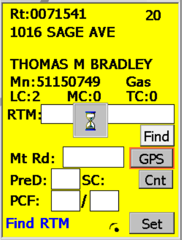
Elster Handhelds
User Guide 64 7. Installing RTMs
To begin the installation process:
1. Press <F> or click Find to read the serial number of the RTM that is within the range of
the short range antenna.
You can also enter the RTM serial number in the Rtm text box and then press Find to
ensure that only the RTM number you entered is searched for.
The lower left corner of the screen displays the status of the Find operation.
a. For Gen 2 RTMs: enter the serial number before pressing Find.
Note: You must enter 7 digits for the serial number. Use a leading zero for serial numbers
less than 1000000.
b. For Gen 2, Gen 2.5 Water and Gen 3 Water RTMs, disconnecting the battery will
erase the serial number. The serial number must be entered because the Find
command will not work.
2. Once the RTM is found, the handheld will display the RTM serial number and its
parameter values as shown below.
Parameter values will vary for pre Gen 5 RTMs.
If Enable sound option if on, a success or fail sound will alert you to the result of
reading.
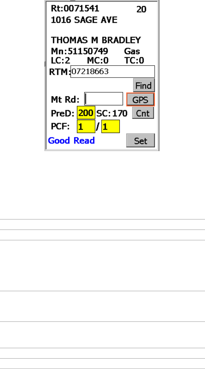
Elster Handhelds
User Guide 65 7. Installing RTMs
3. For pre Gen 5 RTMs, follow the instructions on the screen to place and remove the
programming stick, jumper or magnet. The magnet can be removed after the
programming operation has finished. See Chapter D, “Programming Pre Gen 5
RTMs” for more details on placing the programming stick, jumper or magnet.
For Gen 5 RTMs, follow the instructions below.
Setting gas RTM values (Gen 5)
Setting water RTM values (Gen 5)
Item Description
Mt Rd meter index reading
PreD The predivider value can be set to 1, 2, 4, 5, 7, 9, 10, 20,
50, 100, 200, or 250.
This value represents the number of counts that must be
collected from the meter to represent one count for the
RTM. For example, if the predivider was set to 2, 10 pulse
counts from the meter would be stored as 5 pulse counts
in the RTM.
PCF pressure compensation factor
The pressure compensation factor is represented as a
numerator over a denominator (any number from 1 to
255).
Item Description
Mt Rd meter index reading

Elster Handhelds
User Guide 66 7. Installing RTMs
Programming an RTM
Note: Before programming the RTM, Elster recommends that the RTM be checked to see
if it is recording subcounts correctly.
Checking subcounts
To check subcounts:
1. Press Cnt or <C>.
The current RTM subcount will be returned.
2. Rotate the wriggler on the RTM, counting the rotations.
Refer to your
TRACE VRT Gas Transponder
manual (P/N 52870T010) for details.
3. Reread the subcounts and verify that the subcount value has increased by the
correct number of rotations.
When you have verified the subcounts are recording correctly, proceed to
“Programming the RTM” on page 66.
Programming the RTM
To program the RTM:
1. Enter the desired values and then click Set or press <S>.
The interrogator will read, check and set the parameter values.
PreD The predivider value can be set to 1, 2, 4, 5, 7, 9, 10, 20,
50, 100, 200, or 250.
This value represents the number of counts that must be
collected from the meter to represent one count for the
RTM. For example, if the predivider was set to 2, 10 pulse
counts from the meter would be stored as 5 pulse counts
in the RTM.
L Cnts leak counts
Leak counts can be set to any number from 1 to 9999.
L Hrs hours for leak detect
Leak hours can be set to 0, 1, 2, 3, 4, 6, 8 and 12 (hours
that evenly divide 24 hours)
Item Description
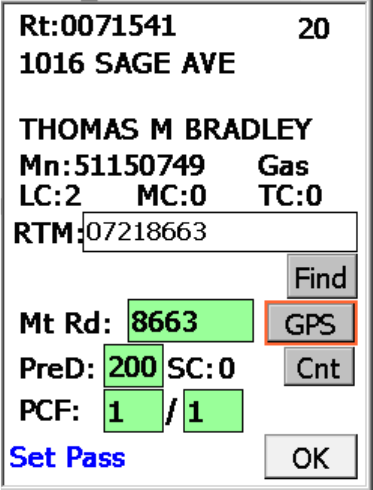
Elster Handhelds
User Guide 67 7. Installing RTMs
The final status will be displayed as either Set Pass or Failed.
After a successful installation:
• The RTM subcount value will be set to zero.
• The status will be displayed as Installed.
2. Press OK to move to the next account.
If the GPS coordinates are zero, the interrogator will automatically read them at this
time.
Using the scanner
The scanner feature is available with installation routes. To use the scanner requires a
Bluetooth card in the handheld device and the scanner must be Bluetooth enabled.
The scanner can be used instead of using Find or typing in the RTM serial number at the
beginning of the installation process.
• To use the scanner, press the scanner trigger while scanning the RTM serial number
bar code label.
A successful scan will cause the handheld to beep and cause the scanner to beep
twice.
The scanned RTM serial number will then be displayed in the RTM field.
See “Scanner and GPS properties” on page 87 for scanner configuration properties for the
handheld device.
Taking GPS coordinates
GPS coordinates can be captured during RTM installation. To use GPS requires a Bluetooth
card in the handheld and the GPS receiver must be Bluetooth enabled.
Note: Turn on the GPS receiver before trying to capture GPS coordinates. The device takes
about 30 - 45 seconds to get a good satellite fix.
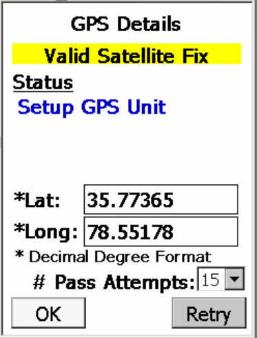
Elster Handhelds
User Guide 68 7. Installing RTMs
Automatically
To capturing GPS coordinates, press OK after a successful RTM install (see “Installing an
RTM” on page 62). If the GPS coordinates are zero, they will automatically be captured
before moving to the next account.
Manually
1. At the install route screen, press GPS or <G> to view the GPS Details screen.
• If the GPS coordinates have not yet been read, moving to the GPS Details screen
will trigger reading the GPS location.
A successful receive will display latitude and longitude values in decimal format.
• If GPS coordinates have been saved, moving to the GPS Details screen will display
the previously captured coordinates.
The Status field describes the various phases of the GPS reading process. First the
GPS port is opened, followed by the setup of the GPS receiver.
Once the device is setup, it reads the RTM location in latitude and longitude values.
A successful read displays a status of
GPS Info Completed
.
2. If the GPS read fails, press Retry or <R> to retry the operation.
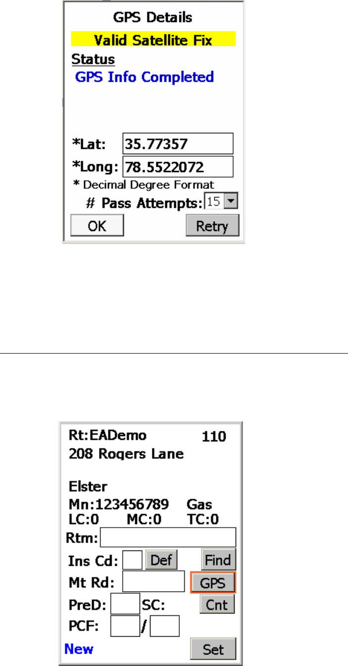
Elster Handhelds
User Guide 69 7. Installing RTMs
3. Click OK to exit the screen and save the coordinate values.
4. When you are finished installing RTMs, turn the GPS receiver off to save its battery life.
See “Scanner and GPS properties” on page 87 for GPS configuration properties for the
handheld device.
Installing EnergyAxis gas modules using the PI 900
The PI 900 installs and programs EnergyAxis Gas modules. To install EnergyAxis Gas
modules:
1. From the Account installation screen, press <F> or click Find.
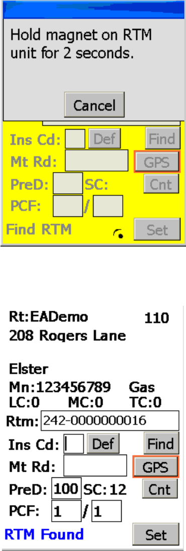
Elster Handhelds
User Guide 70 7. Installing RTMs
The screen prompts you to hold a magnet on the RTM for 2 seconds.
2. Hold a magnet on the side of the RTM for 2 seconds.
Click Cancel to return to the installation screen.
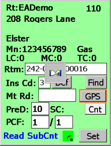
Elster Handhelds
User Guide 71 7. Installing RTMs
3. After the 2 seconds, the RTM broadcasts the RTM number and is recognized by the
handheld.
The handheld displays the following information for the RTM:
•RTM number
•PreDiv
• Sub-counts
•PCF
• Status message
The handheld prompts you to read the Subcounts. See “Checking subcounts” on
page 71 for details.
Checking subcounts
To check subcounts:
1. Press Cnt or <C>.
The current RTM subcount will be returned.
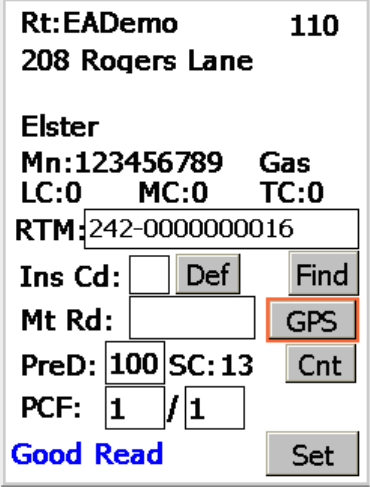
Elster Handhelds
User Guide 72 7. Installing RTMs
2. Rotate the wriggler on the RTM, counting the rotations.
Refer to your
EnergyAxis Gas Module
manual for details.
3. Reread the subcounts and verify that the subcount value has increased by the
correct number of rotations.
When you have verified the subcounts are recording correctly, proceed to
“Programming the RTM” on page 72.
Programming the RTM
To program the RTM:
1. Click Def or press <D>.
The screen displays the Ins Def Codes (Installation Definition Codes).
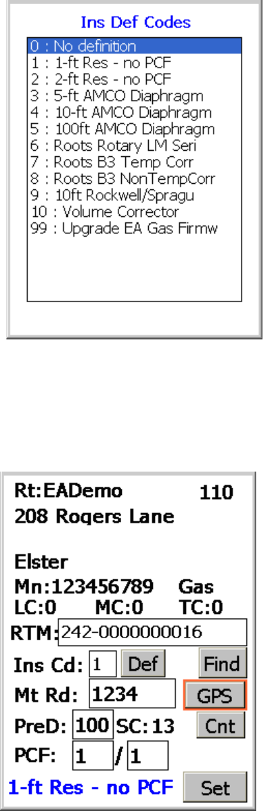
Elster Handhelds
User Guide 73 7. Installing RTMs
2. Select the appropriate Installation Definition Code from the list.
Note: Code 99 is reserved for upgrading the module firmware using a file obtained from
Elster Customer Support. Use this code only if directed to by Elster.
Note: Refer to the
Route Manager User Guide
for details on configuring Installation
Definition Codes.
3. Enter the visual read index value in the Mt Rd.
— Or —
If you wish to use the default values, select the Installation Definition Code = 0.
a. Enter the PreD value.
b. Enter the PCF value.
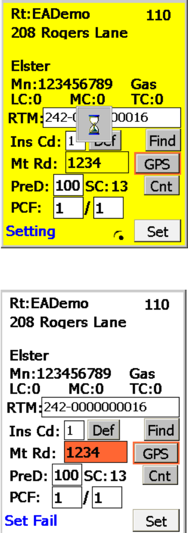
Elster Handhelds
User Guide 74 7. Installing RTMs
4. Click Set or press <S>.
The interrogator will read, check and set the parameter values.
The final status will be displayed as either Set Pass or Failed.
After a successful installation:
• The RTM subcount value will be set to zero.
• The status will be displayed as Installed.
• The date and time will be set.
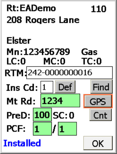
Elster Handhelds
User Guide 75 7. Installing RTMs
5. Press OK to move to the next account.
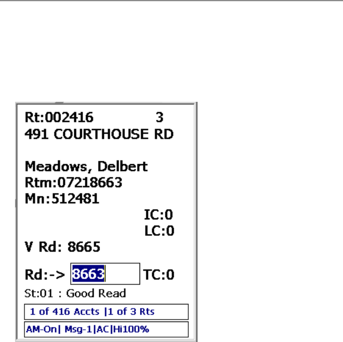
Elster Handhelds
User Guide 76 8. RTM Verification
8 RTM Verification
The handheld device can also be used to verify the RTM index reading against the visual
meter reading. In Route Manager the route must be set to a Read Type = Verify before the
route is downloaded to the handheld device. After the download, check that the Route
Type is Verify when you select the route on the handheld device.
Reading a meter with verification
Note: The appearance of the handheld display is configurable. Refer to the
Route
Manager User Guide
for details. Your handheld display may appear different
from examples shown in this manual.
1. After selecting the route, the Account screen displays with a field for the verify read.
2. If the current read value is -2 and the RTM number is not blank, then pressing
<Enter> will trigger an RF read of the RTM along with verification of the RTM reading
against a visual meter reading.
3. After pressing <Enter>, the screen shown below will appear.
Rt: Route ID
Rtm: RTM Serial Number
Mn: Meter Number IC: Instruction Code
MT: Meter Type LC: Location Code
V Rd: Visual Read
Rd: Index Read –>: Direction of
Data Entry
TC: Trouble Code
St: Account Status
D:0-35 Number of VRT details (requests)
available
AM-off/on AutoMove enabled
Msg-0 There are 0 messages in the
alarm category.
AC / BT : shows the source of
power for the handheld:
•AC from cradle
• BT from battery
Hi100% : shows that the battery is
charged at 100%
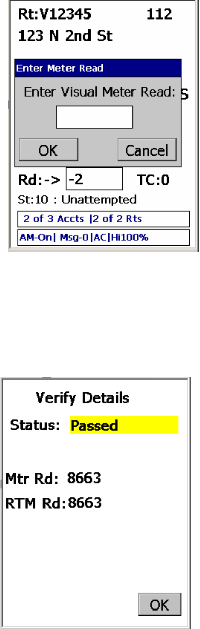
Elster Handhelds
User Guide 77 8. RTM Verification
4. Enter the meter read obtained by visually reading the dials associated with the meter
and press <Enter> or OK to continue.
If the difference between the visual meter read and the RTM read is less than or
equal to the allowed tolerance as set through Route Manager, then the verification
will pass.
5. Press <Enter> or OK to return to the data entry screen.
The verification information will be returned back to Route Manager.
If the difference between the visual meter read and the RTM read is greater than the
allowed tolerance as set through Route Manager, then the verification will fail.
6. Press <Enter> or OK to return to the data entry screen.
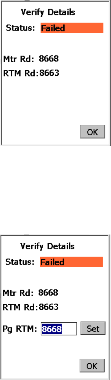
Elster Handhelds
User Guide 78 8. RTM Verification
The failed verification information will be returned back to Route Manager.
Programming for verification
If the route has the Verify Allow Programming flag set, then you will be able to reprogram
the RTM with a new index value after a failed verification. The screen displayed below
shows a failed verification.
After failed verification
1. Enter the new index value as the Pg RTM value and touch Set or press <Enter> to
continue with programming.
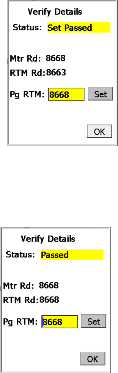
Elster Handhelds
User Guide 79 8. RTM Verification
After a successful program operation, the screen below will appear.
2. Press <Enter> or touch OK to continue.
After successful verification
You also have the option of reprogramming the index after a successful read verification.
After the verification test passes, the screen below will be displayed.
1. Touch Set to program the RTM with the value shown in the Pg RTM box, or press
<Enter> to continue without programming.
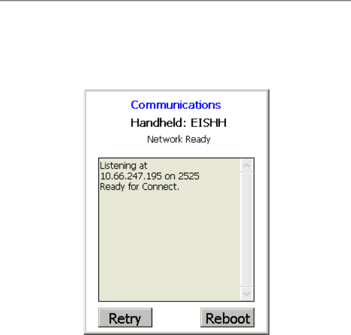
Elster Handhelds
User Guide 80 9. Communicating with Route Manager
9 Communicating with Route Manager
In order to move routes back and forth between the handheld device and Route Manager,
the handheld device must first be set up to communicate over Ethernet to the Route
Manager computer. Ethernet communications can be done over the utility's local area
network using either dynamic or static IP addressing. If the Route Manager PC is not on a
network, communications to the handheld device can be done via a router connection or
through an Ethernet cross over cable connecting the handheld device cradle to the PC
using static IP addressing. Contact Elster for more details on how to set up
communications if you are not on a network. If you are on a network, your utility IT
administrator should be able to assist in the initial communications setup.
Once the initial setup has been done to connect the handheld device to Route Manager,
follow the steps below to move routes back and forth between the handheld device and
Route Manager.
Establishing communications
1. Ensure that the handheld device's cradle and the computer with Route Manager are
connected with the proper cable (Ethernet).
2. Ensure that the handheld is properly seated in its cradle.
3. Make sure the handheld is in communications mode: press <F3> from the Main
Menu.
4. Open Route Manager on your computer.
5. Select Devices.
6. From the Handheld Selection drop list select the desired handheld.
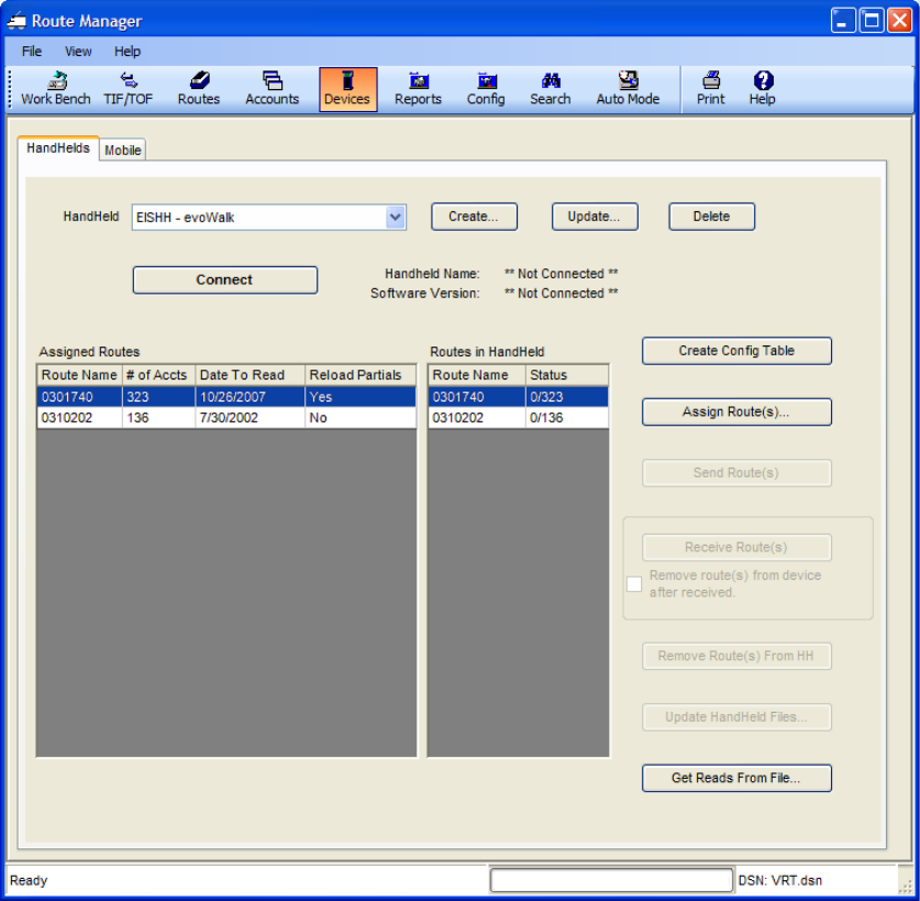
Elster Handhelds
User Guide 81 9. Communicating with Route Manager
7. Click Connect.
Upon successful connection:
•The Connect button will display Disconnect.
• The Serial Number and Handheld Software Version will be displayed directly
beneath the Disconnect button.
• The Handheld function buttons will be disabled.
• The Handheld Communication buttons will be enabled.
• If Routes exist in the handheld they will be displayed in the Routes in Handheld
display list.
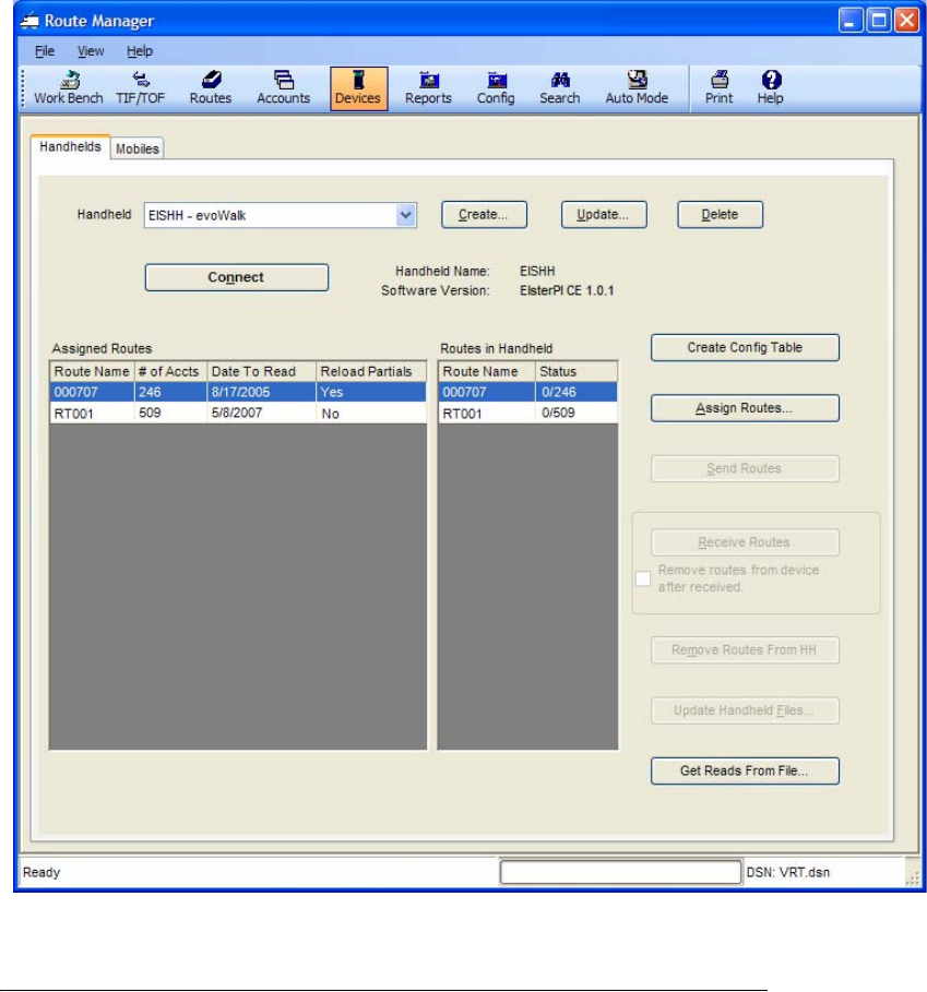
Elster Handhelds
User Guide 82 9. Communicating with Route Manager
Downloading routes from Route Manager to device
Note: To prevent overwriting data on the handheld, the
Send Route
command will be
disabled if the routes on the handheld contain meter readings that have not yet
been uploaded to Route Manager. To delete routes on a handheld without
uploading existing data, click
Remove Routes from HH
. See “Removing routes
from the handheld device” on page 83 for details.
1. Follow the connection steps as described in “Establishing communications” on page
80.
2. Ensure that the desired Route is assigned to the connected handheld.
3. Highlight the desired routes in the Assigned Routes display list.
4. Click Send Route to send the route to the Handheld Device.
After the Route has been sent successfully to the Handheld device, the Routes in
Handheld display grid will be updated to display the sent routes.
5. Press <Esc> on the handheld to exit from the Route Manager Communications
screen.
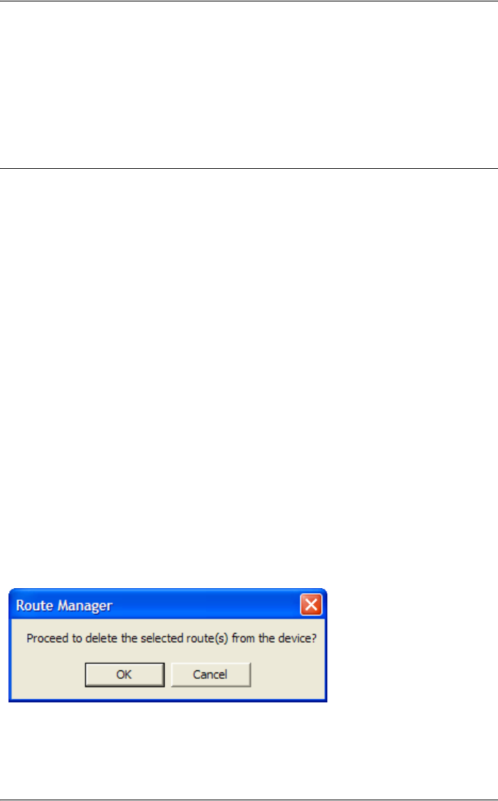
Elster Handhelds
User Guide 83 9. Communicating with Route Manager
Uploading routes from device to Route Manager
1. Follow the connection steps as described in “Establishing communications” on page
80.
2. Select the desired Routes to receive from the Routes in Handheld display list.
3. Click Receive Route to start the process.
Upon successful completion the Route Status will change to Transferred.
Removing routes from the handheld device
Each time you download routes to the handheld device, all existing routes on the handheld
will be deleted. Old routes are not deleted until AFTER the new routes have been
successfully downloaded, so you may not have enough room on the handheld to store
both the old routes and the new routes at the same time. If your routes are extremely
large, you may wish to delete existing routes from the handheld device before
downloading new routes.
You may follow either of the two procedures below to delete routes from the handheld
device.
After a successful upload
1. Follow the connection steps as described in “Establishing communications” on page
80.
2. Select the Remove Routes from device after received check box.
3. Click Receive Routes.
Without receiving the routes first
1. Follow the connection steps as described in “Establishing communications” on page
80.
2. Once connected, select the route to remove from the Routes in Handheld display
list.
3. Click Remove Routes from HH.
4. Click OK on the message box.
Updating handheld files
Route Manager can be used to download files other than route files to the handheld
device. You may need to download a new executable or configuration file to the handheld
device after advice from Elster Technical Support. The instructions below show the steps
involved.
1. Follow the connection steps as described in “Establishing communications” on page
80.
2. Click the Update Handheld File button.
The Update Handheld Files screen displays.
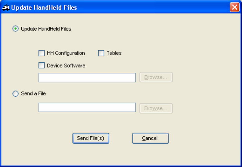
Elster Handhelds
User Guide 84 9. Communicating with Route Manager
3. Select one of the two options: Update Handheld Files or Send a File.
a. Update Handheld Files - Select the check boxes for the files you wish to update
and then click Send Files.
• HH Configuration - updates the handheld with new or changed configuration
files (see the
Route Manager User Guide
for details).
• Device Software - select and browse to the location of the UPGSOFTW.ZIP file
that will be transferred to the handheld. This file can contain one or more of the
following files:
Note: Elster recommends that you only use this option only if directed to by Elster
Customer Support.
• ELSTERPI.EXE - a new executable for the handheld software
•*.HEX - a new firmware file to be downloaded to the PI 500 or PI 900
handheld RF cards
•*.HEX - a new firmware file to be downloaded to the EnergyAxis gas
module.
• Tables - downloads new database template files (*.DBQ) to the handheld.
Note: Elster recommends that you only use this option only if directed to by Elster
Customer Support.
— Or —
b. Send a File
Browse becomes active.
4. Type or Browse for the desired file names and locations.
5. When the desired files are selected, click Send Files to begin updating the
handheld’s files.
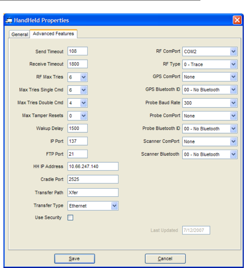
Elster Handhelds
User Guide 85 10. Setting up devices in Route Manager
10Setting up devices in Route Manager
Before connecting the handheld device to Route Manager, the handheld device must be
set up in Route Manager with the correct communication properties. The
Route Manager
User Guide
details how to set up a handheld device. The information below gives
information specifically about the handheld device properties.
Handheld device properties
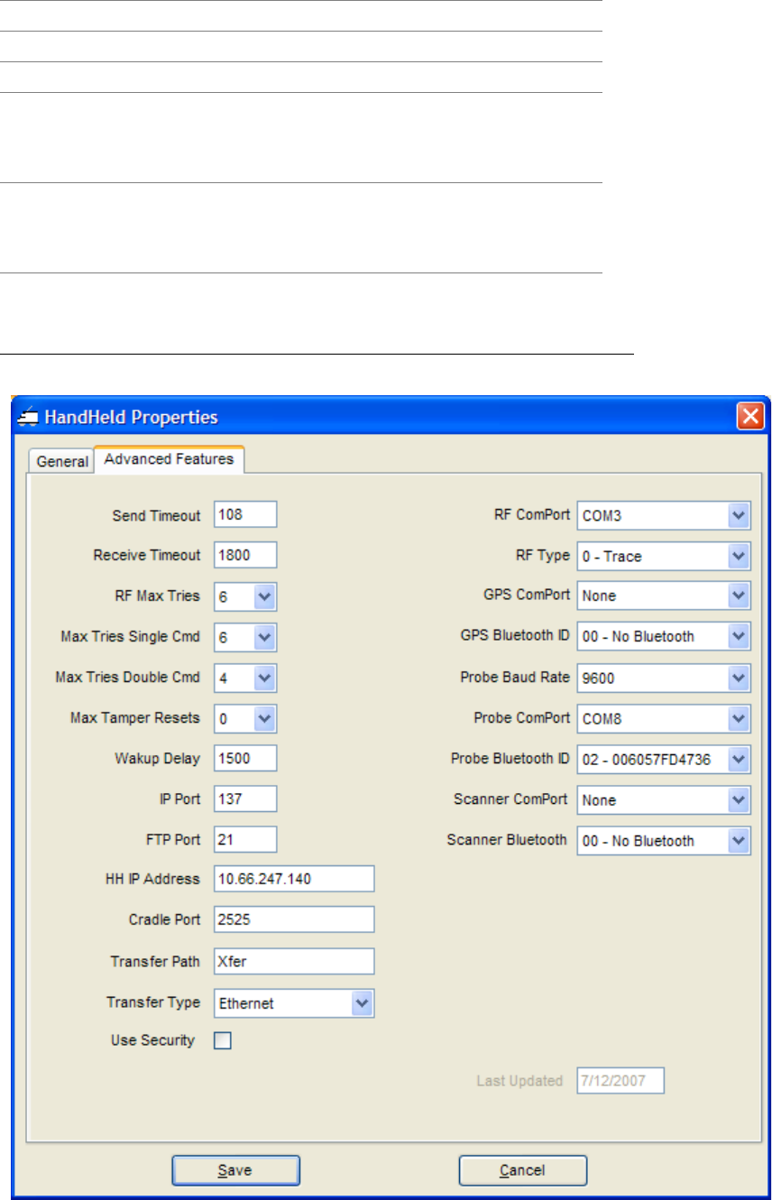
Elster Handhelds
User Guide 86 10. Setting up devices in Route Manager
Make sure the following values are added correctly.
VersaProbe properties
Property Value
Handheld IP Address: IP address of handheld
Transfer Type: Ethernet
RF ComPort: Select the appropriate port for the handheld:
• for PI 500 - ComPort 2
• for PI 900 - ComPort 3
• for evoWalk - ComPort 3
RF Type Select the appropriate system:
•Trace - 0
•evolution - 1
•EnergyAxis - 2
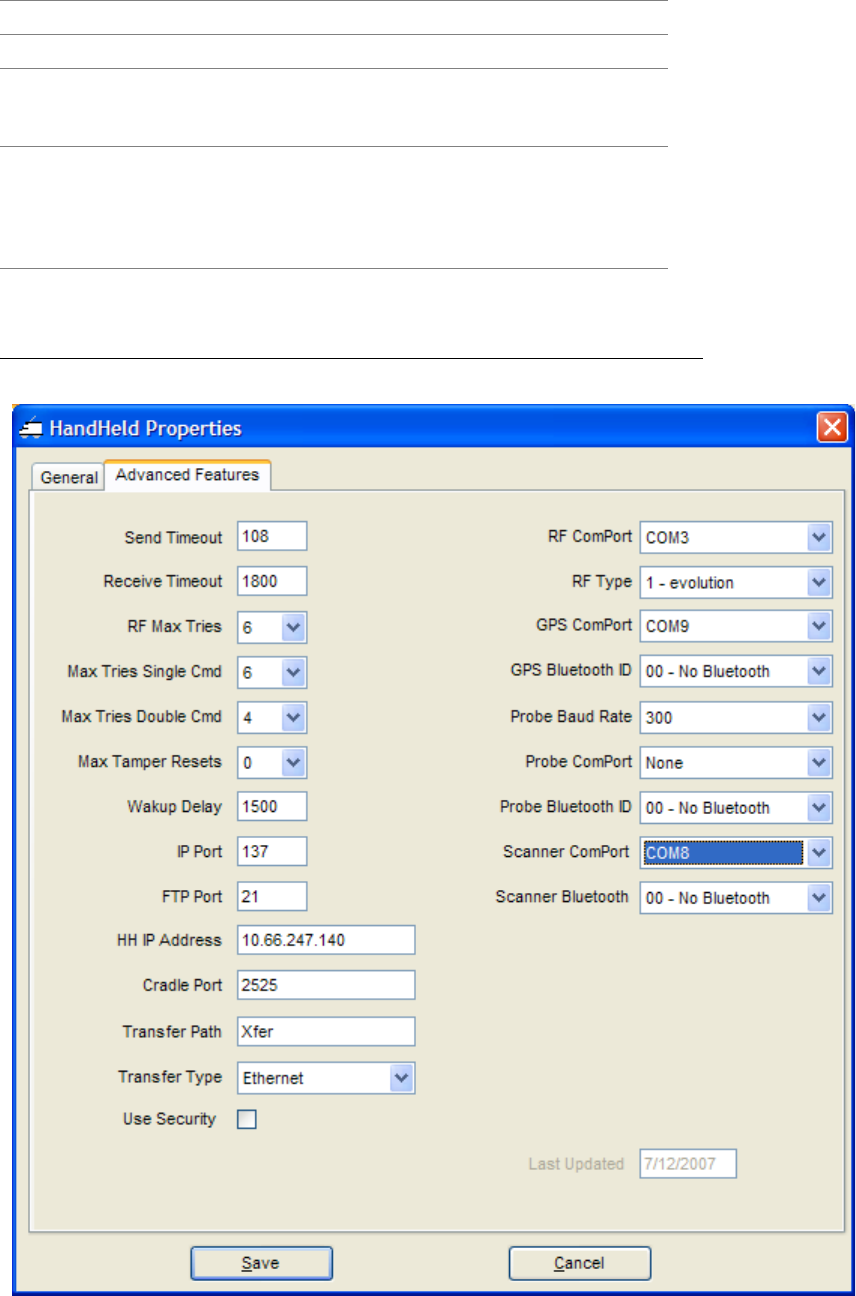
Elster Handhelds
User Guide 87 10. Setting up devices in Route Manager
Make sure the following values are added correctly.
Scanner and GPS properties
Property Value
Probe Baud Rate: 9600
Probe ComPort: Select the appropriate ComPort:
• Com8 for Bluetooth Communication
• Com1 for Serial Communication
Probe Bluetooth ID: Select appropriate Bluetooth ID of the device
Note: You will find this ID in the VersaProbe
communication mode and It is created in Route
Manager under
Configuration > Misc Codes >
VersaProbe Bluetooth ID > Create.

Elster Handhelds
User Guide 88 10. Setting up devices in Route Manager
Make sure the following values are added correctly.
Property Value
GPS ComPort: COM9
Scanner ComPort: • COM8
•None

Elster Handhelds
User Guide 89 A. Accelerator keys for meter reading
A Accelerator keys for meter reading
Accelerator Keys Action
A Account Details
B Jump to Beginning of current route
C Clear Reading
D Detail History / TOU for Current Account. Pressing <Enter>
key initiates RF interrogation for the selected item
E Jump to End of current route
F Force account to Unattempted (only for manual read)
G General Interrogation of the entered RTM.
HSearch menu
I Instruction code.
J Jump (by sequence)
L Location code.
M Message (Comments). Messages can be added or edited
if allowed.
N Jump to Next route
O ErrOr log
P Jump to Previous route
Q Set the Re-Sequence flag for upload back to CIS
R RF Read Index and all VRT requests for current account.
Pressing <Enter> key initiates RF interrogation for the
selected Account
S Skip code. Allows selection of skip code for current
account.
T Trouble code. Allows selection of trouble code for current
account.
U Jump to next Unread account
V Jump to VersaProbe connection screen
X Jump to record displayed prior to the jump (Only available
for B,E,H,J,U accelerator keys)
F1 Displays key list with description. When an item is
selected the choice is executed (if appropriate).
F2 Route Selection / Load
F3 Current Route Summary or Communication on the main
screen
F4 Configuration Settings

Elster Handhelds
User Guide 90 B. Accelerator keys for installing RTMs
B Accelerator keys for installing RTMs
Accelerator Keys Action
A Account Details
B Jump to Beginning of current route
C Read Sub Counts
E Jump to End of current route
FFind RTM
G GPS Screen
HSearch menu
I Instruction code.
J Jump (by sequence)
L Location code.
M Message (Comments). Messages can be added or edited
if allowed.
N Jump to Next route
P Jump to Previous route
Q Set the Re-Sequence flag for upload to CIS
S Set RTM values
T Trouble code. Allows selection of trouble code for current
account.
X Cancel last move
F1 Displays key list with description. When an item is
selected the choice is executed (if appropriate).
F2 Route Selection / Load
F3 Current Route Summary or Communication on the main
screen
F4 Displays change out screen

Elster Handhelds
User Guide 91 C. Troubleshooting
C Troubleshooting
General troubleshooting
1. Click on the screen with the stylus if the navigation using device keys does not
produce expected results.
2. Try to reboot handheld:
a. PI 500 - press and hold <F1>+ <0> +<9> keys together for few seconds.
b. evoWalk and PI 900 - hold down the <R> + <X> + <¦> keys down simultaneously
for several seconds until the screen goes blank.
— Or —
Refer to the
Elster Handhelds Installation and Administration Guide
.
Trouble in connecting the device to Route Manager
1. Make sure the handheld device is correctly seated in the cradle and there is not any
contaminated material in between the cradle and handheld's contacts.
2. If using a router (instead of Company's Network connections) for handheld and host
PC communication, make sure that the firewall on the host PC is disabled, from the
Windows Start menu, select Settings > Control Panel > Windows Firewall and
select option OFF.
3. Check if the Handheld's LED is glowing either green or red. If not then maybe the AC
charger is faulty.
For Interrogator PC card error messages or further information, please contact:
Customer Support
Elster
208 South Rogers Lane
Raleigh, NC 27610
T+1 800 338 5251 (US toll free)
F+1 919 212 4801
trace.support@us.elster.com
energyaxis.support@us.elster.com

Elster Handhelds
User Guide 92 D. Programming Pre Gen 5 RTMs
D Programming Pre Gen 5 RTMs
Gen 2 RTMs (FCC ID G8J3GNAMR8)
Gen 2 RTMs (serial numbers < 2,500,000) must be programmed using a four position
programming stick (EIS P/N 52800G101). Place the programming stick over the four
jumpers located on the lower right corner of the circuit border which is visible from the
back of the RTM when prompted to do so by the handheld device. Remove the
programming stick before the verify process begins as prompted by the handheld device.
For Gen 2 RTMs, you can read the serial number, index and subcounts. You can program
the serial number and the index. If the battery is disconnected, the serial number is lost.
You cannot read the RTM when the serial number is lost, but you can program the serial
number and index in order to prepare the RTM for reading.
Gen 2.5 water pit RTMs (FCC ID G8JPIT25)
Gen 2.5 Water Pit RTMs are programmed using a magnet on the programming switch.
When prompted by the handheld device, place a magnet on the bottom of the RTM
(opposite side of the RTR or HRT wires). The magnet may be removed after the
programming is complete.
For these RTMs, you can read the serial number, index and subcounts. You can program
the index.
Gen 2.5 water remote RTMs (FCC ID G8JGEN25)
Gen 2.5 Water Remote RTMs are programmed using a programming stick. Before
programming, remove the four seal screws and cover from the RTM. Locate the group of
three jumper pins on the lower left corner of the circuit card. When prompted by the
handheld device to place the magnet, slide the socket end of the programming stick over
these pins (polarity is not critical). (The handheld device cannot distinguish between the pit
and remote Gen 2.5 RTMs, so the prompt always refers to the magnet.)
For these RTMs, you can read the serial number, index and subcounts. You can program
the index.
Gen 3.x water remote RTMs (FCC ID G8JGEN03)
Gen 3.x Water Remote RTMs are programmed using a magnet. It is not necessary to
remove the enclosure cover to program these RTMs. Locate the target molded into the
lower right hand side of the enclosure. The texture is different from the rest of the box.
When prompted by the handheld device to place the magnet, position and hold the
magnet on the target.
For these RTMs, you can read the serial number, index and subcounts. You can program
the index.
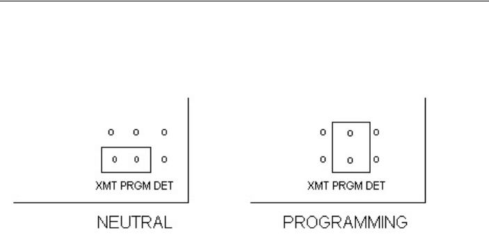
Elster Handhelds
User Guide 93 D. Programming Pre Gen 5 RTMs
Gen 3.x gas remote RTMs (FCC ID G8JGEN03)
Gen 3.x Gas Remote RTMs are programmed using a jumper. The jumper is supplied from
the factory in a neutral position. When a RTM is programmed, the jumper is repositioned
onto the PRGM pins. These two positions are illustrated below.
The positions shown above are the ONLY TWO valid positions for this jumper. Any RTM
which is found with its jumper in any other position should be corrected to the NEUTRAL
position for maximum performance.
When prompted by the handheld device, place the jumper into the PROGRAMMING
position. Remove the jumper when prompted by the handheld device and place back into
the NEUTRAL position.
For these RTMs, you can read the serial number, predivider, type, revision and subcounts.
You can program the index.
Elster Handhelds
User Guide 94 Index
Index
Symbols
<Enter> key 19
<Esc> key 19
<N> key 19
<Tab> key 19
<Y> key 19
A
accelerator keys 16
account
adding trouble code 33
clearing index read 32
forcing unattempted 32
reading 29, 30
Account Appointments screen 51
Account Data Entry screen 45
Account Details screen 41, 47
accounts
navigating 29
adding
skip code 33
trouble code 33
AMR
components 11
AMR. See
automatic meter reading.
11
antenna, external
Dap CE5240X 14
safety 14, 15
antennas 11
appointments
route 29
arrow keys 19
Auto Move 26
automatic meter reading 11
Automove 32
B
Bluetooth
GPS 67
scanner 67
C
Capture GPS on Read 27
changing out
index 59
meter 59
charging
handheld 21
checking
subcounts 66
clearing
index read 32
communicating
with Route Manager 80
components
of AMR 11
Con Type 26
configuring
VersaProbe 52
contacting
Customer Support 91
Cradle 26
Customer Support
contacting 91
D
database
warning 17
downloading
routes from Route Manager 82
E
EnergyAxis
RTM installation tool 17
entering
index read 30
messages 34
Error Log screen 49
evoWalk 10
description 14
exiting
Elster Interrogator software 27
Extend Battery Life 27
F
files
exchanging 24
forcing unattempted
account 32
Ftp 27
functions
Route 16
Route Manager Communications 16
G
getting
GPS coordinates 67
GPS
configuring in Route Manager 87
getting coordinates 67
H
handheld
about 10, 13
charging 21
configuring in Route Manager 85
Dap CE5240X 13
EnergyAxis 14
evolution 14
evoWalk 10
functionality 11
holding 22
logging in 21
main menu screen 24
menu commands 16
operating 16
PI 500 10
PI 900 10
Radix 14
rebooting 21
resetting 21
TRACE 13
turning on/off 20
updating configuration 26
updating files 83
viewing configuration 25
hardware
optional 17
HH Name 26
History
reading 39
holding
handheld 22
I
index, general
reading 39
Installation Definition Codes screen 73
installing
RTM 62
RTMs 59
installing RTMs
using PI 500 59
using PI 900 69
Instruction Code screen 48
interrogator, def. 11
IP 26
J
jumping
beginning of route 41
end of route 41
Elster Handhelds
User Guide 95 Index
next route 41
next unread account 42
previous route 41
sequence number 41
jumps, about 41
K
keyboard
Dap CE5240x 18
Radix 19
L
latitude 17
Location Code screen 48
logging in
handheld 21
longitude 17
M
menu commands 16
messages
entering 34
meter reading
automatic 16
MSG 34
N
navigating
accounts 29
O
obtaining readings
methods 10
P
PI 500 10
PI 500, desc. 13
PI 900 10
PI 900, desc. 14
programming
for verification 78
RTM 66
R
read data
processing 16
Read screen 30, 32
reading
account 29, 30
general index 39
history 39
meters 20
multiple parameters 36
TOU 39
with VersaProbe 55
reading, manually 31
rebooting
handheld 21
removing
resequencing flag 36
routes from handheld 83
reprogramming
after failed verificiation 78
after successful verification 79
resequence flag
setting 35
resequencing
route 35
resequencing flag
removing 36
resetting
handheld 21
RMT installation tool
requirements 17
route
appointments 29
resequencing 35
selecting 24
Route Appointments screen 50
Route Manager 16
communicating with 24
communications 80
configuring GPS 87
configuring handheld 85
configuring handhelds 85
configuring scanner 87
configuring VersaProbe 86
downloading routes 82
uploading routes 83
Route Manager Communication 24
Route Manager Communications 20
Route Selection 20, 24
Route Summary screen 46
Routes Selection screen 46
RTM installation tool
EnergyAxis 17
TRACE 17
RTM, def. 11
S
safety
notices 8
procedures 8
scanner
configuring in Route Manager 87
searching
address 43
customer 44
route 42
setting
resequence flag 35
skip code
adding 33
software
exiting 27
specifications
Dap CE5240X 13
Radix 15
stylus
using 20
T
Tamper Try 26
TOU
reading 39
TRACE
RTM installation tool 17
Trouble Codes screen 50
Trouble Message 34
turning on/off 20
U
Update Configuration 26
updating
handheld files 83
UPGSOFTW.ZIP 84
uploading
routes to Route Manager 83
using
scanner 67
V
verification, failed 78
verification, successful 79
Verify Allow Programming flag 78
verifying
RTM index reads 76
VersaProbe 52
Bluetooth communication 53
configuring in Route Manager 86
connecting 55
reading 55
serial communication 52
View Configuration 24, 25
viewing
Account Details 41
help 46
W
warranty 8

© 2007 by Elster. All rights reserved.
No part of this software or documentation may be reproduced,
transmitted, processed or recorded by any means or form,
electronic, mechanical, photographic or otherwise, translated
to another language, or be released to any third party without
the express written consent of the Elster.
Printed in the United States of America.
P/N 52808T510 December 2007
Elster
208 S Rogers Lane
Raleigh, NC 27610-2144
United States
T +1 800 338 5251 (US toll free)
F +1 919 212 4801
trace.support@us.elster.com
energyaxis.support@us.elster.com
www.elster.com
TRACE and EnergyAxis are registered trademarks and evolution
and Route Manager are trademarks of Elster. Other products
and company names mentioned herein may be the trademarks
and/or registered trademarks of their respective owners.
About Elster Group
Elster Group is the world's leading
manufacturer and supplier of highly
accurate, high quality, integrated metering
and utilization solutions to the gas,
electricity, and water industries. In addition,
through its subsidiary Ipsen International, it
is the leading global manufacturer of high-
level thermo- chemical treatment
equipment.
The group has over 8,500 staff and
operations in 38 countries, focused in
North and South America, Europe, and
Asia. Elster's high quality products and
systems reflect the wealth of knowledge
and experience gained from over 170 years
of dedication to measuring energy and
scarce natural resources.