Elster Solutions HHI05 PI900W User Manual
Elster Solutions, LLC PI900W
UserManual.wiki
>
Elster Solutions
>
HHI05 User Manual
User Manual
Navigation menu
Upload a User Manual
Namespaces
Wiki Guide
HTML
PDF
Info
Views
User Manual
Discussion / Help
Navigation
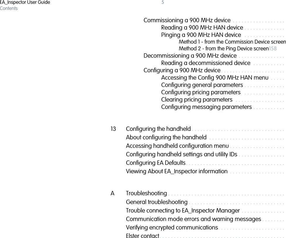


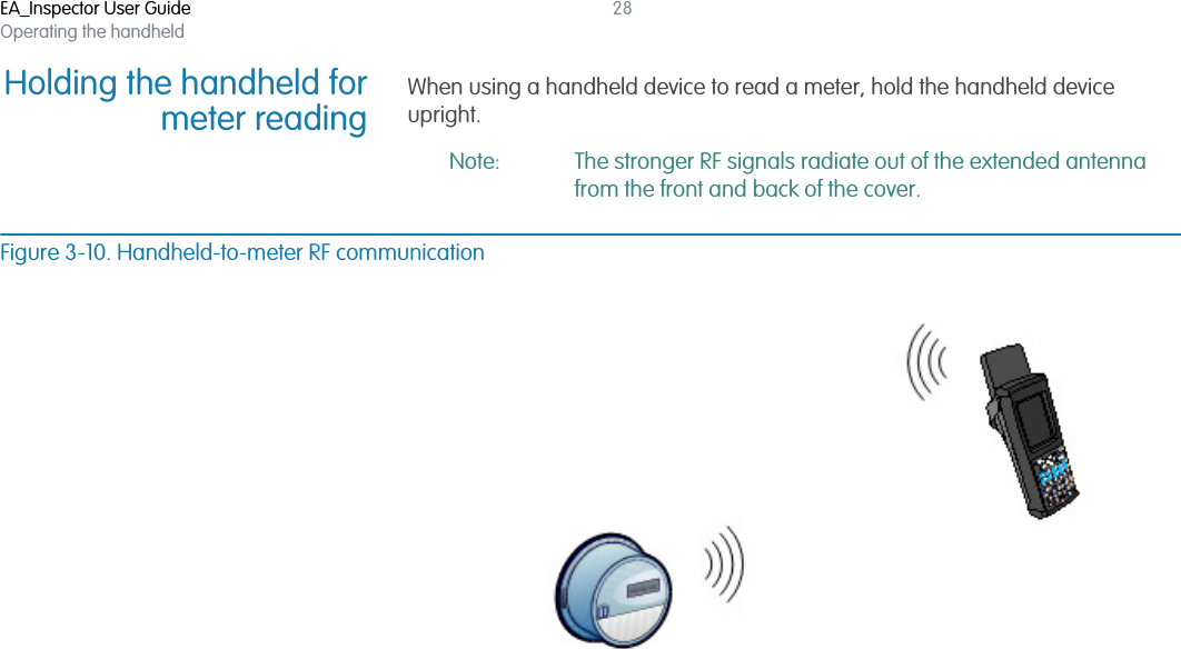
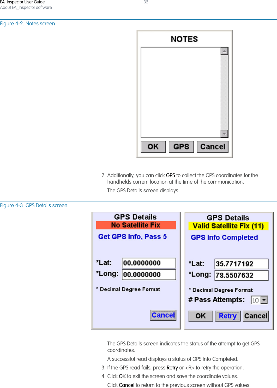
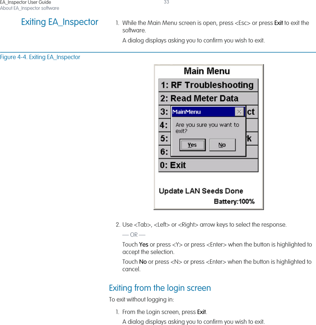
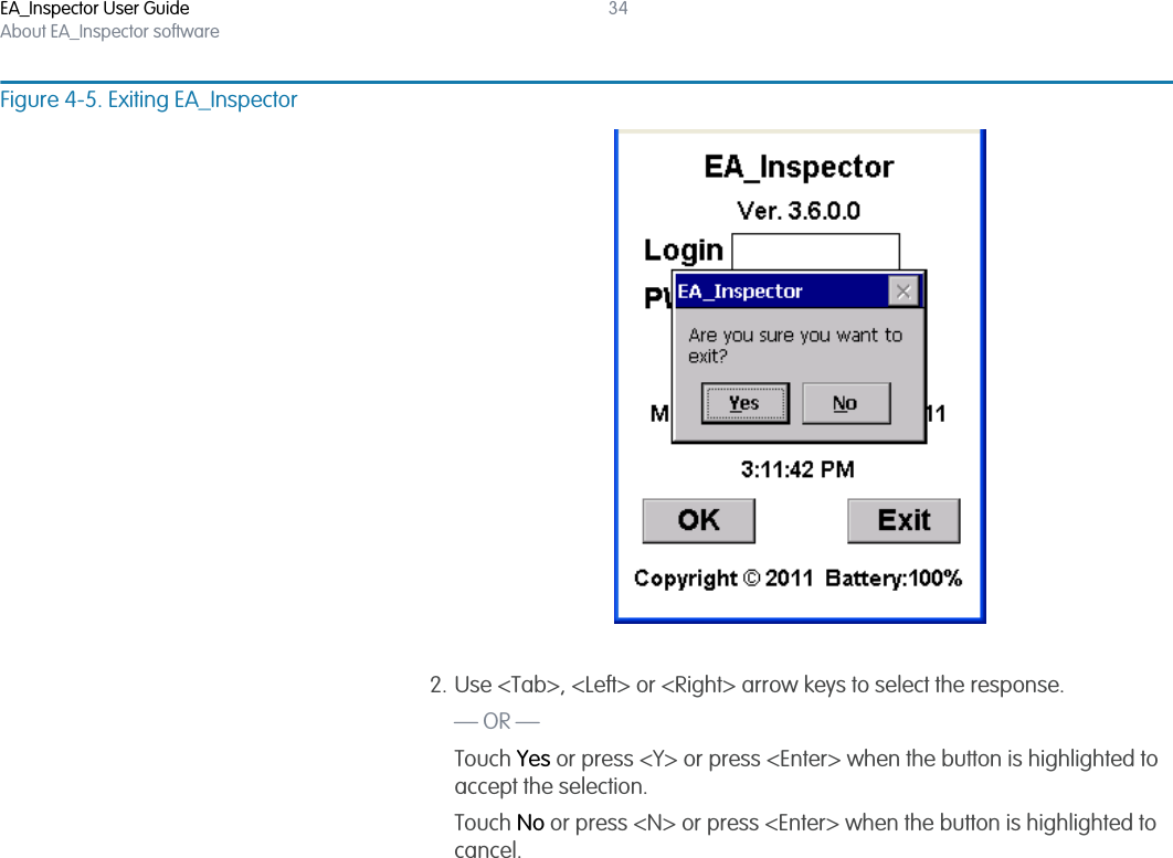
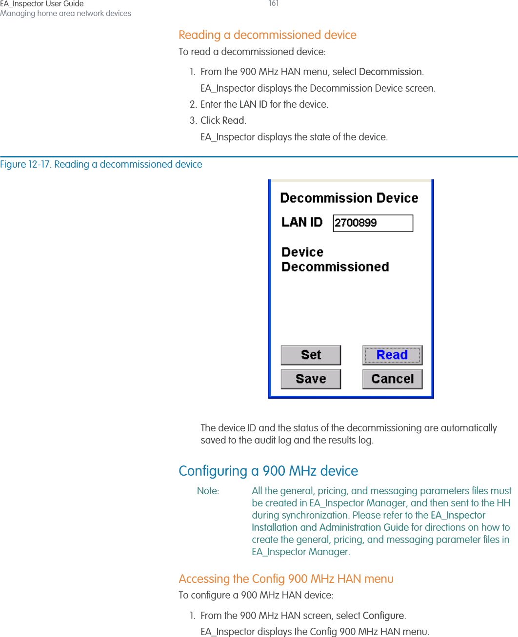
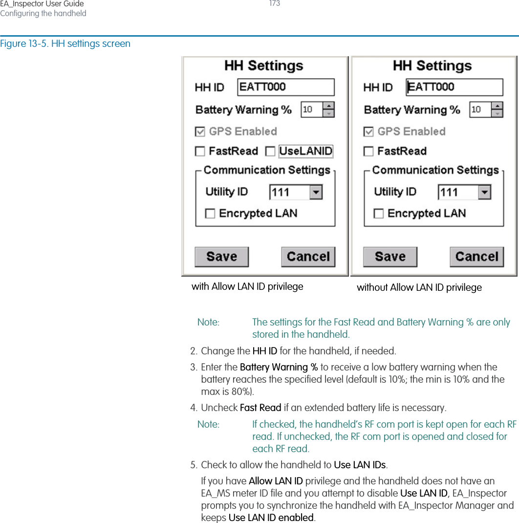
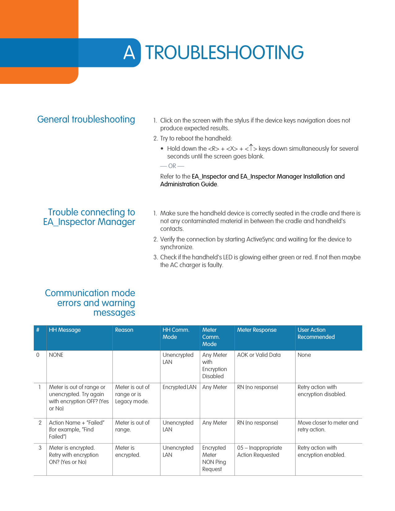
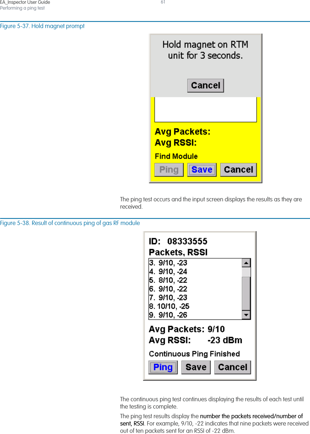
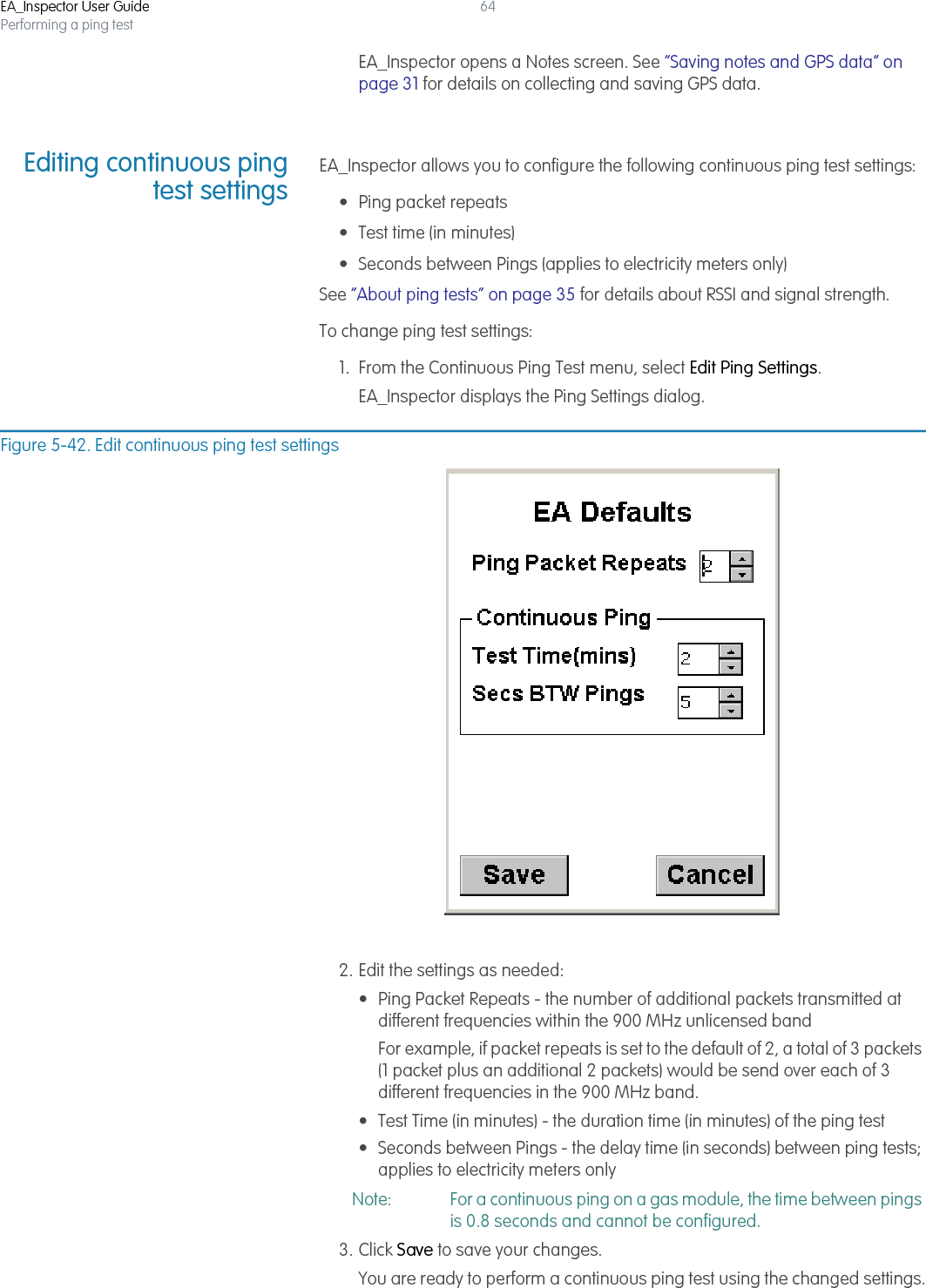
![EA_Inspector User GuidePerforming a ping test41Figure 5-8. Communication warningsIf you receive a communication error or warning message [Figure 5-8], see “Communication mode errors and warning messages” on page 177 for details on troubleshooting communication problems.5. Click Save to save the results to a file for uploading into EA_Inspector Manager.EA_Inspector opens a Notes screen. See “Saving notes and GPS data” on page 31 for details on collecting and saving GPS data.](https://usermanual.wiki/Elster-Solutions/HHI05/User-Guide-1801993-Page-41.png)

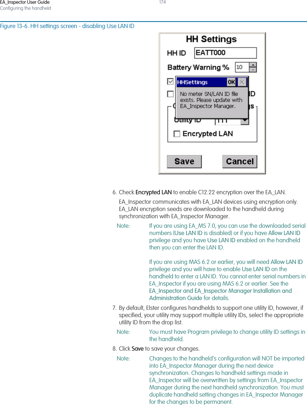
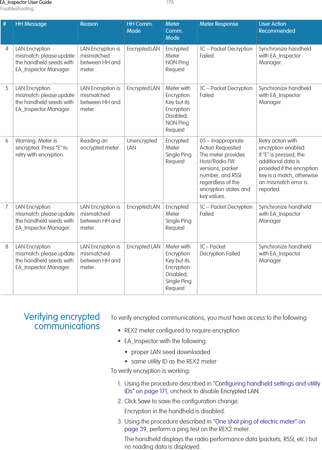
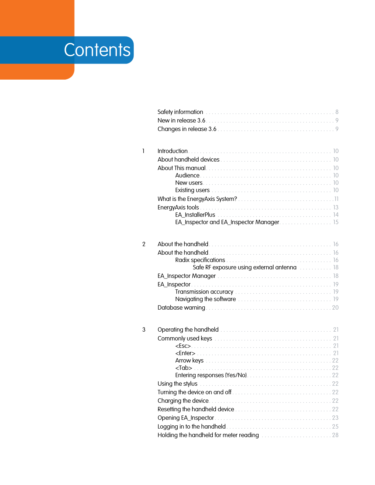
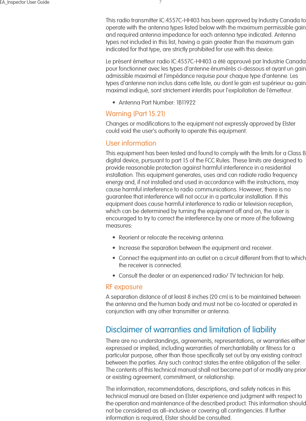
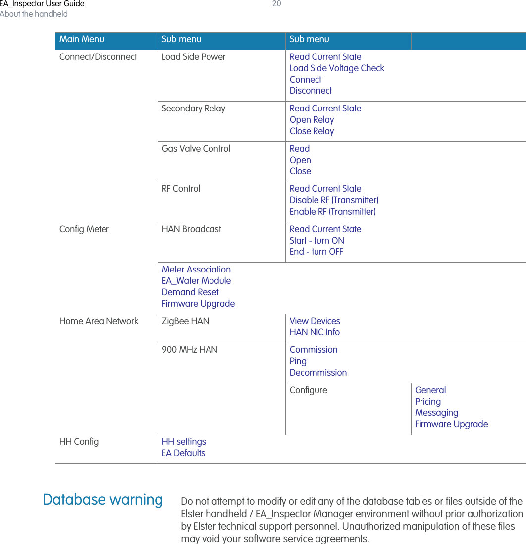
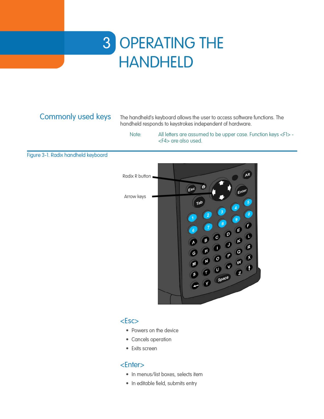
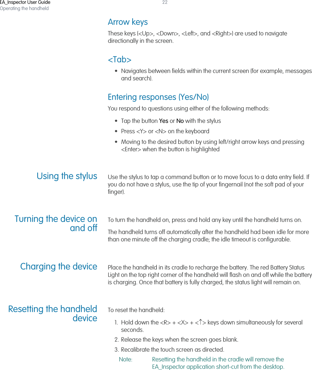
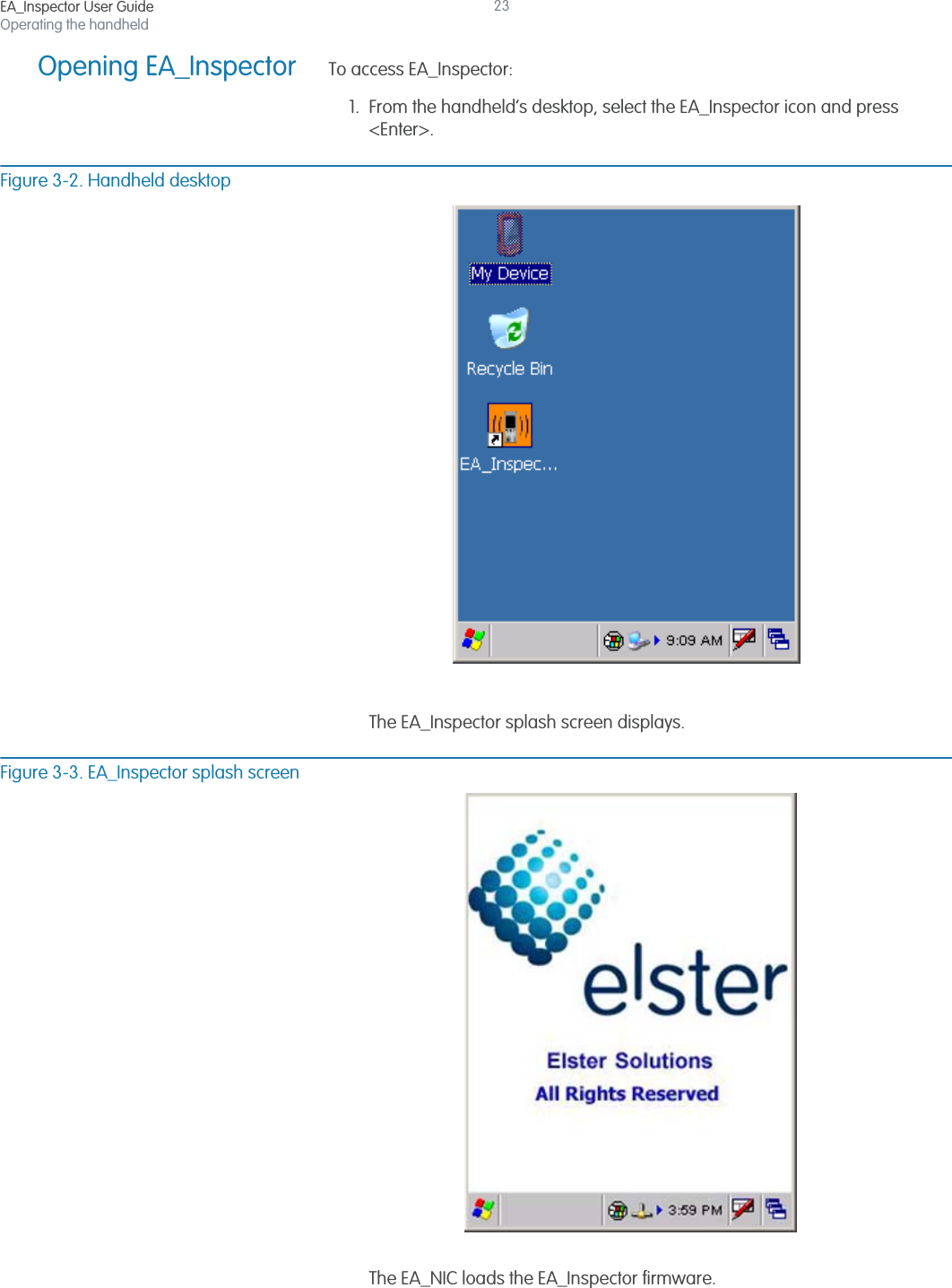
![EA_Inspector User GuideDisconnecting and reconnecting meters87Figure 9-8. Communication warningsIf you receive a communication error or warning message [Figure 9-8], see “Communication mode errors and warning messages” on page 177 for details on troubleshooting communication problems.Checking load sidevoltageBecause a service control switch will not connect if load side voltage is present. To check the status of load side voltage:1. From the Load Side Power menu, select Load Side Voltage Check.EA_Inspector queries the meter and displays the status of the meter’s load side voltage.Read Current State resultsLoad Side Voltage Check display resultsCommunication failureaa. no response from meter.Communication failurePower is disconnected No load side voltageConnection is pending No load side voltagePower is disconnected with load side voltage presentLoad side voltage is presentPower is connected Power is presentDisconnect is pending Power is presentConnect/Disconnect cannot be operated for unregistered REX meterConnect/Disconnect cannot be operated for unregistered REX meter](https://usermanual.wiki/Elster-Solutions/HHI05/User-Guide-1801993-Page-87.png)

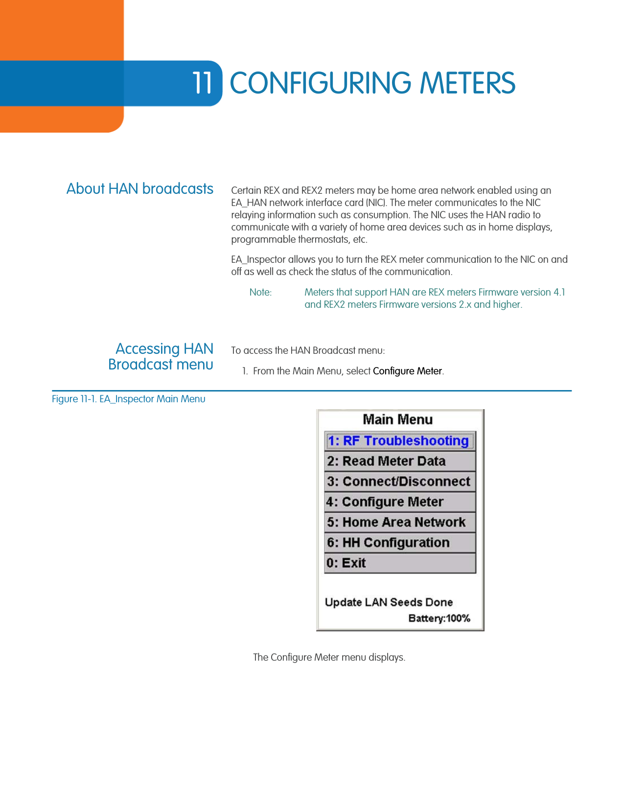
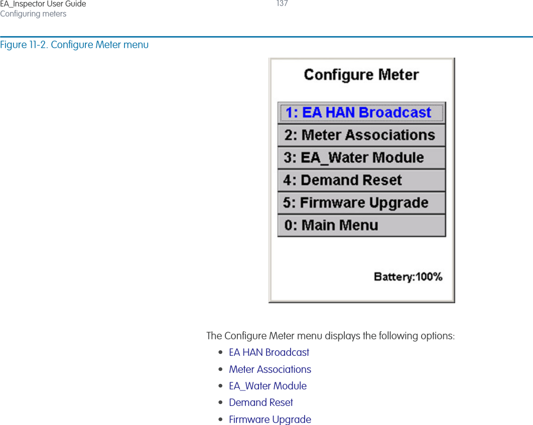
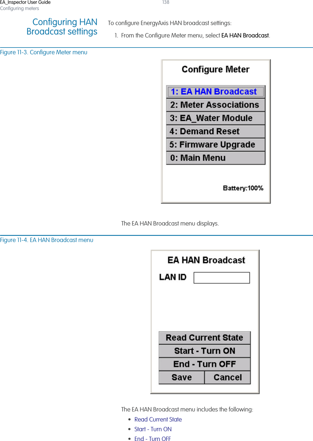
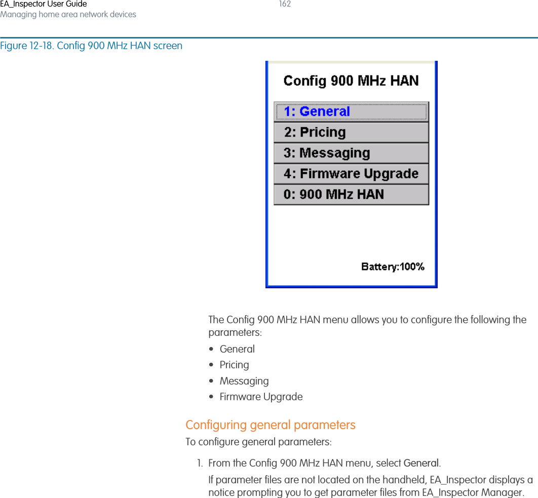
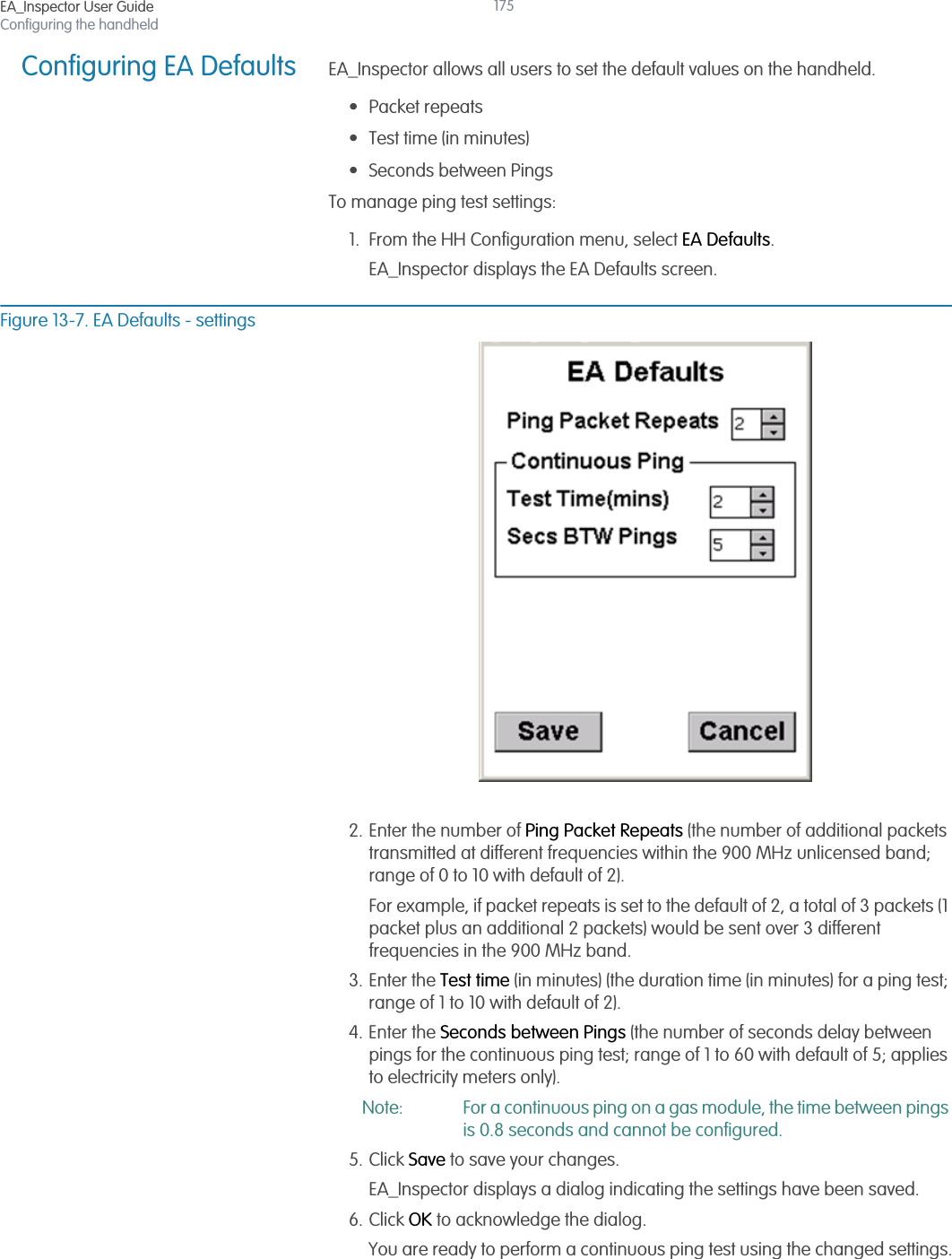
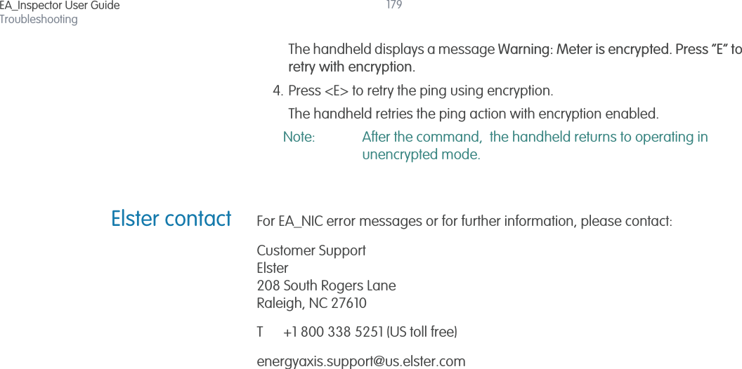
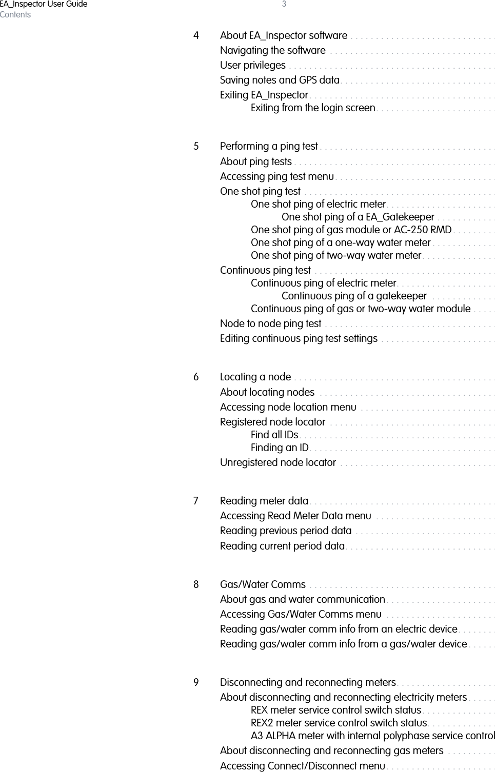
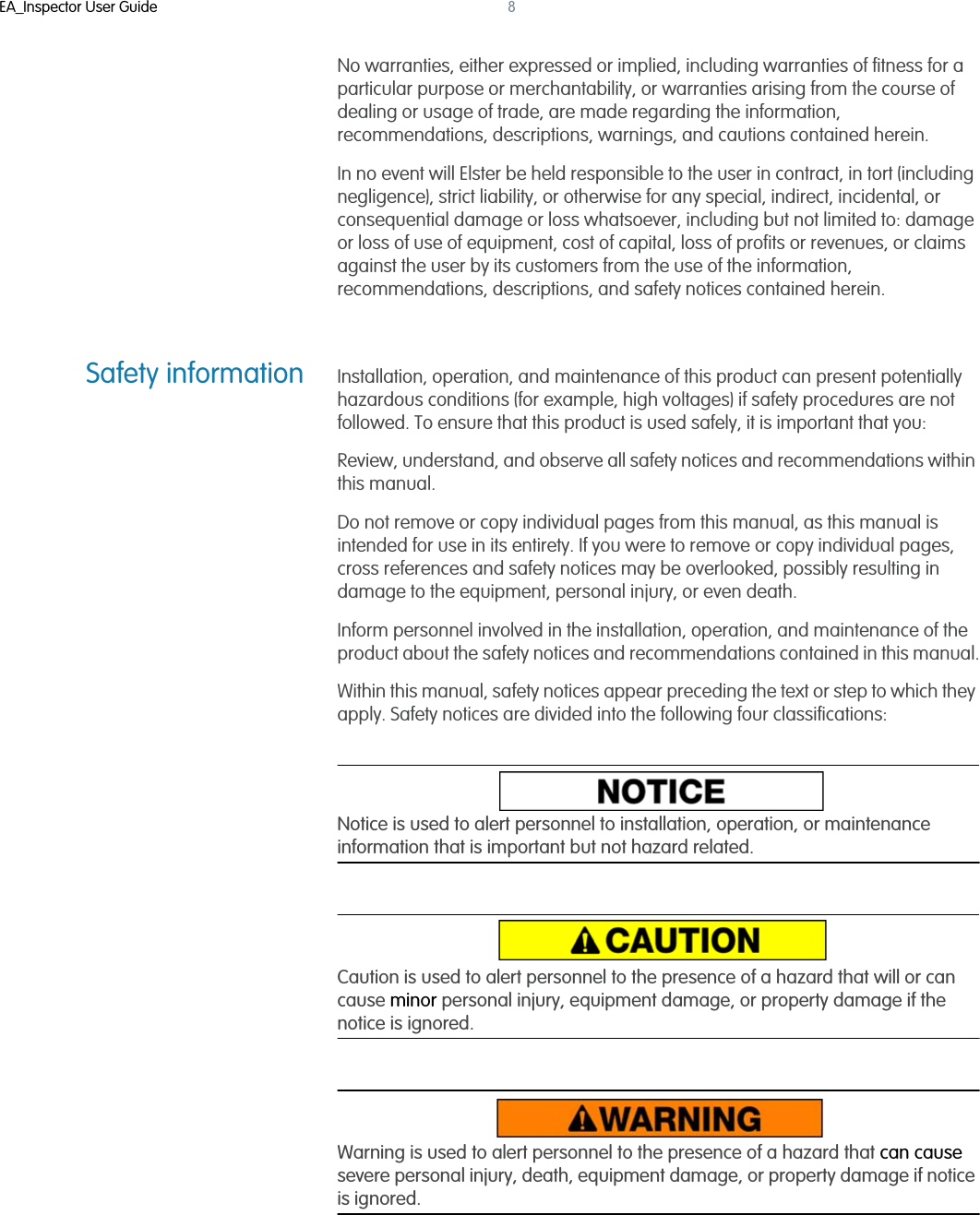
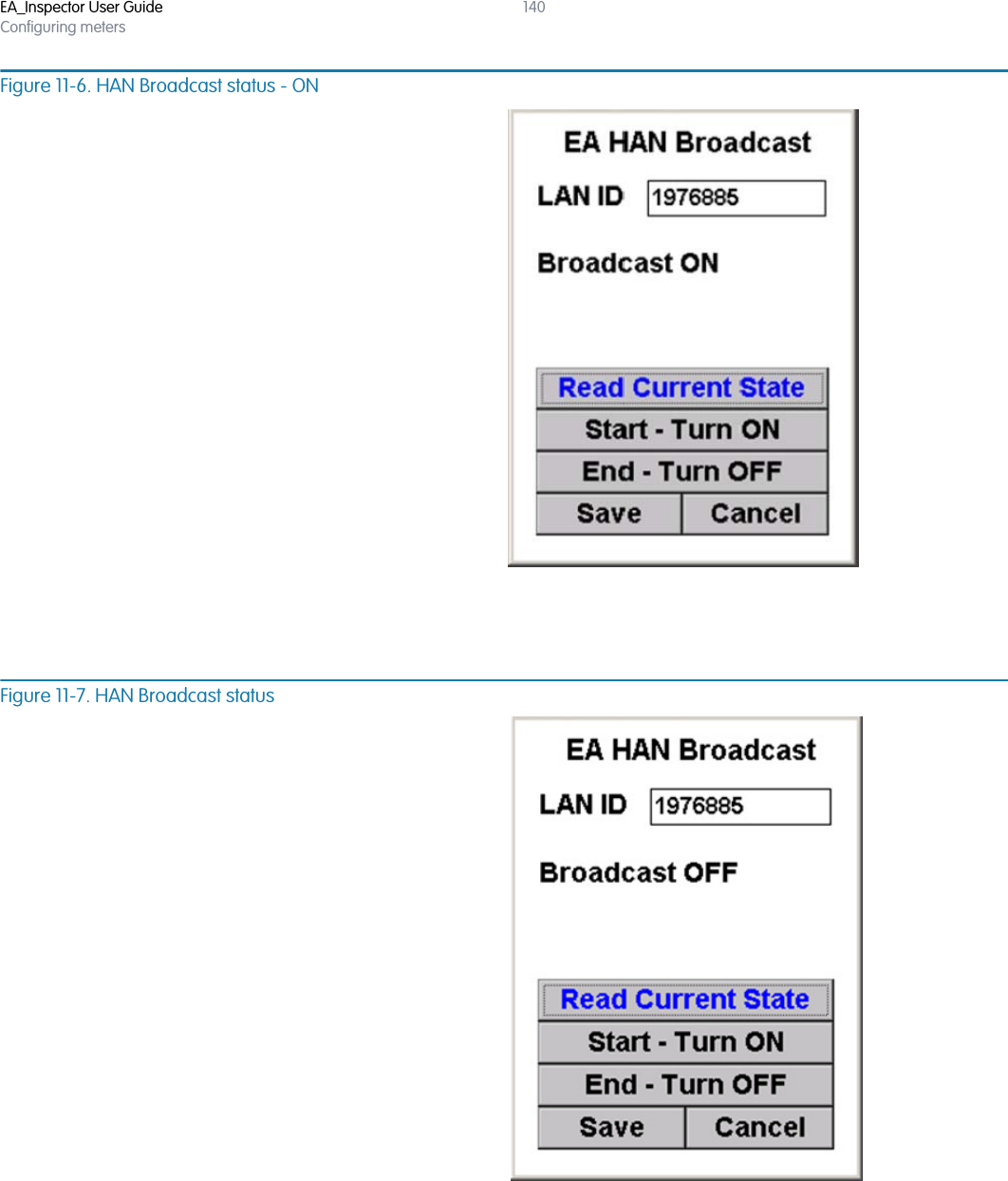
![EA_Inspector User GuideConfiguring meters139Checking the status ofthe meter’s HANbroadcastTo check the status of a meter’s HAN broadcast:1. From the EA HAN Broadcast menu, enter the LAN ID of the selected meter.Figure 11-5. EA HAN Broadcast menu2. Select Read Current State.If the meter selected supports HAN, the handheld displays the status of the HAN Broadcast.If the selected meter does not support HAN, the handheld displays the message “Broadcast not supported in REX v#.”If you receive a communication error or warning message [Figure 11-8], see “Communication mode errors and warning messages” on page 177 for details on troubleshooting communication problems.](https://usermanual.wiki/Elster-Solutions/HHI05/User-Guide-1801993-Page-139.png)
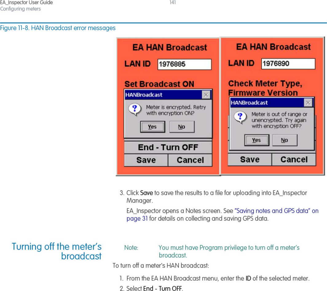
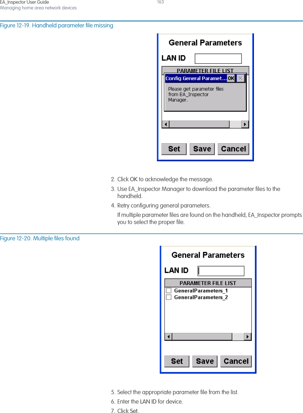
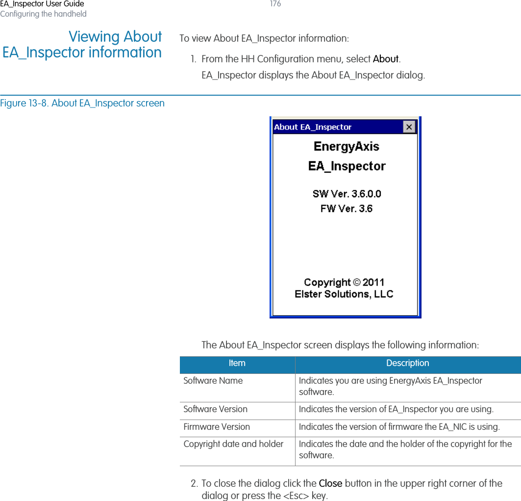
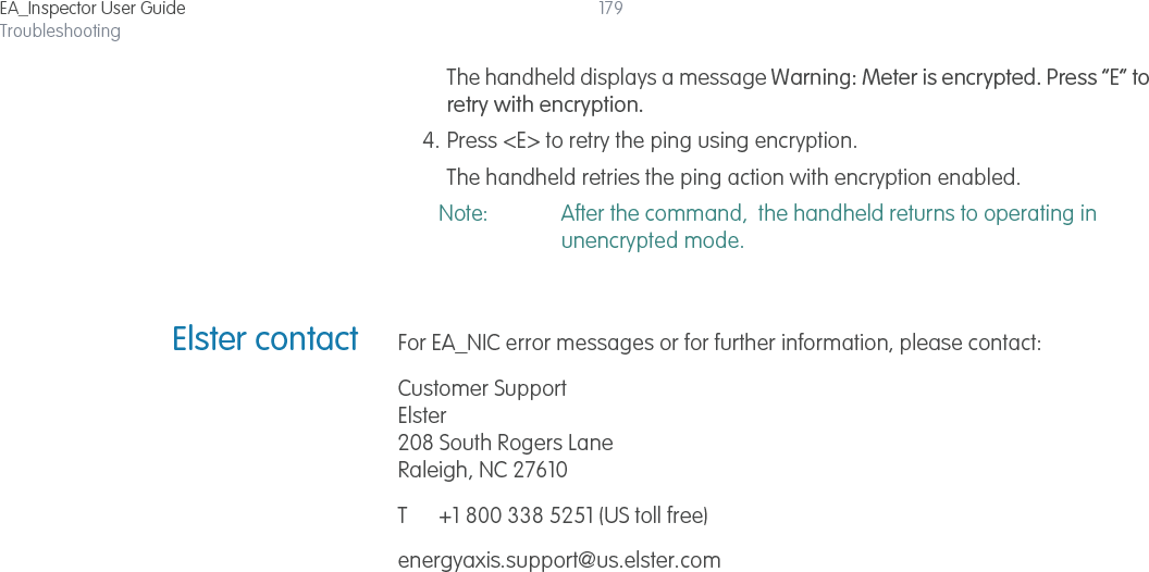
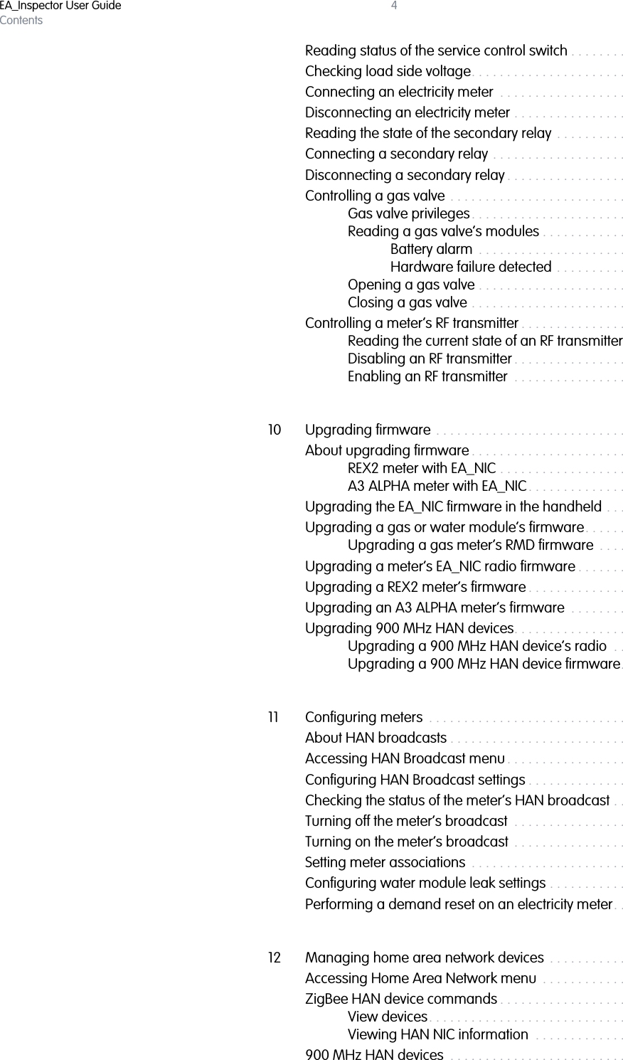
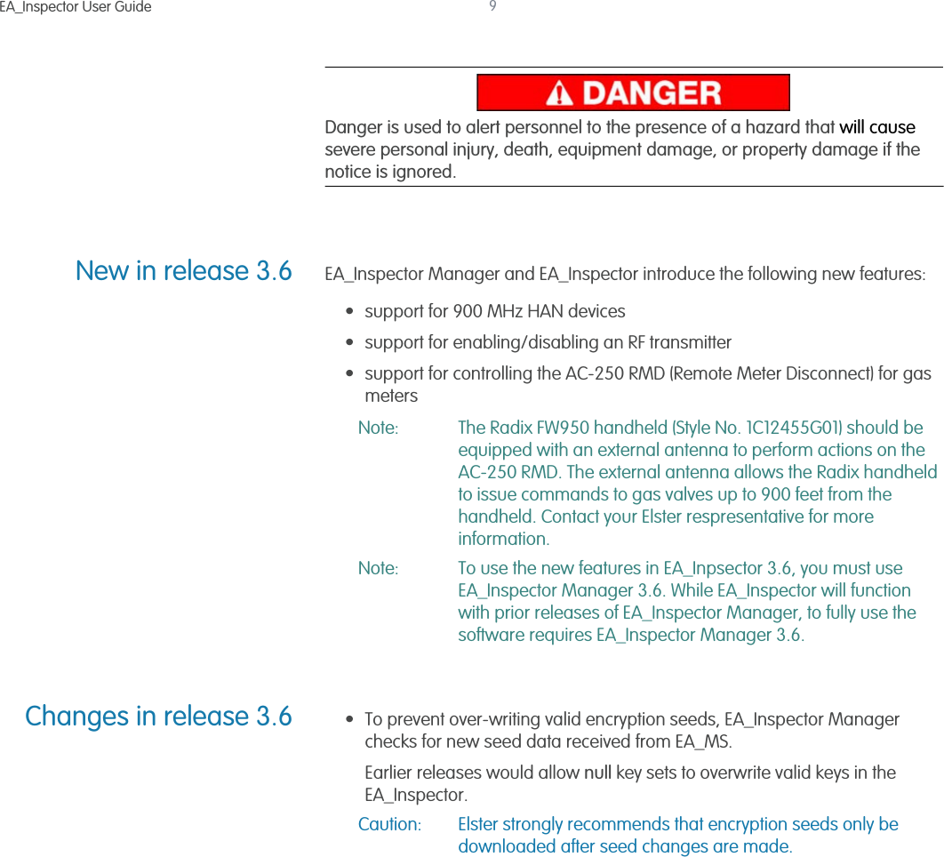
![EA_Inspector User GuideConfiguring meters142Figure 11-9. Turn OFF BroadcastFigure 11-10. HAN Broadcast - OFFIf the selected meter does not support HAN, the handheld displays the message “Broadcast not supported in REX v#.”If you receive a communication error or warning message [Figure 11-8], see “Communication mode errors and warning messages” on page 177 for details on troubleshooting communication problems.3. Click Save to save the results to a file for uploading into EA_Inspector Manager.](https://usermanual.wiki/Elster-Solutions/HHI05/User-Guide-1801993-Page-142.png)
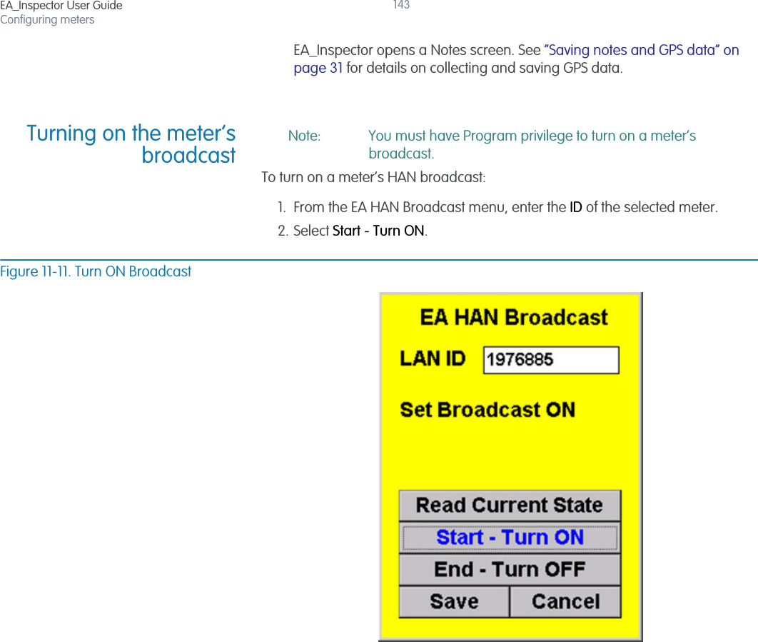
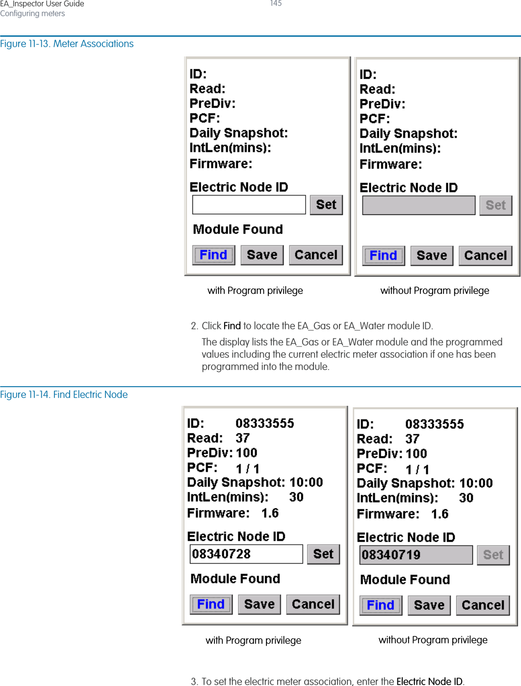
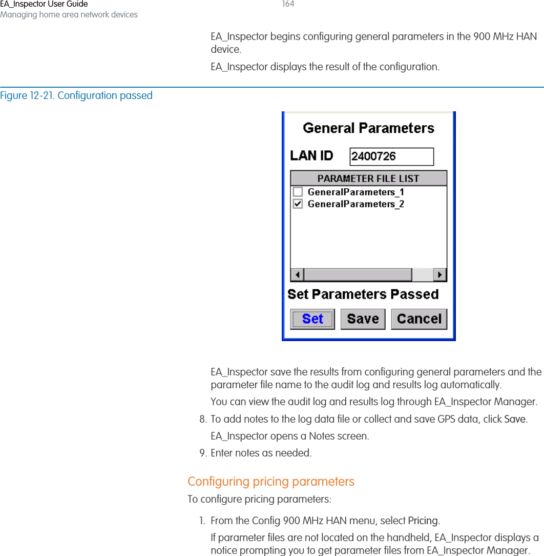
![EA_Inspector User GuideConfiguring meters144Figure 11-12. HAN Broadcast - ONIf the selected meter does not support HAN, the handheld displays the message “Broadcast not supported in REX v#.”If you receive a communication error or warning message [Figure 11-8], see “Communication mode errors and warning messages” on page 177 for details on troubleshooting communication problems.3. Click Save to save the results to a file for uploading into EA_Inspector Manager.EA_Inspector opens a Notes screen. See “Saving notes and GPS data” on page 31 for details on collecting and saving GPS data.Setting meterassociationsNote: You must have Program privilege to use the Set function.The Meter Associations menu allows you to write an electric meter association into an EA_Gas or two-way EA_Water 2.0 module. 1. From the Configure Meter menu, select Meter Associations.The Meter Associations dialog displays.](https://usermanual.wiki/Elster-Solutions/HHI05/User-Guide-1801993-Page-144.png)