Elster Solutions VRT01 VRT Residential Gas Transponder User Manual CERTIFICATE OF COMPLIANCE
Elster Solutions, LLC VRT Residential Gas Transponder CERTIFICATE OF COMPLIANCE
UserManual.wiki
>
Elster Solutions
>
VRT01 User Manual
Users Manual Revised
Navigation menu
Upload a User Manual
Namespaces
Wiki Guide
HTML
PDF
Info
Views
User Manual
Discussion / Help
Navigation

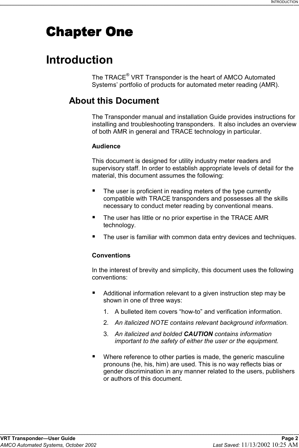
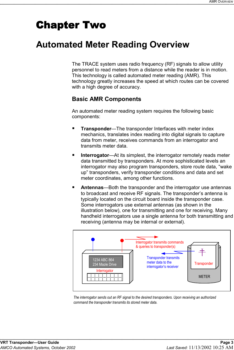
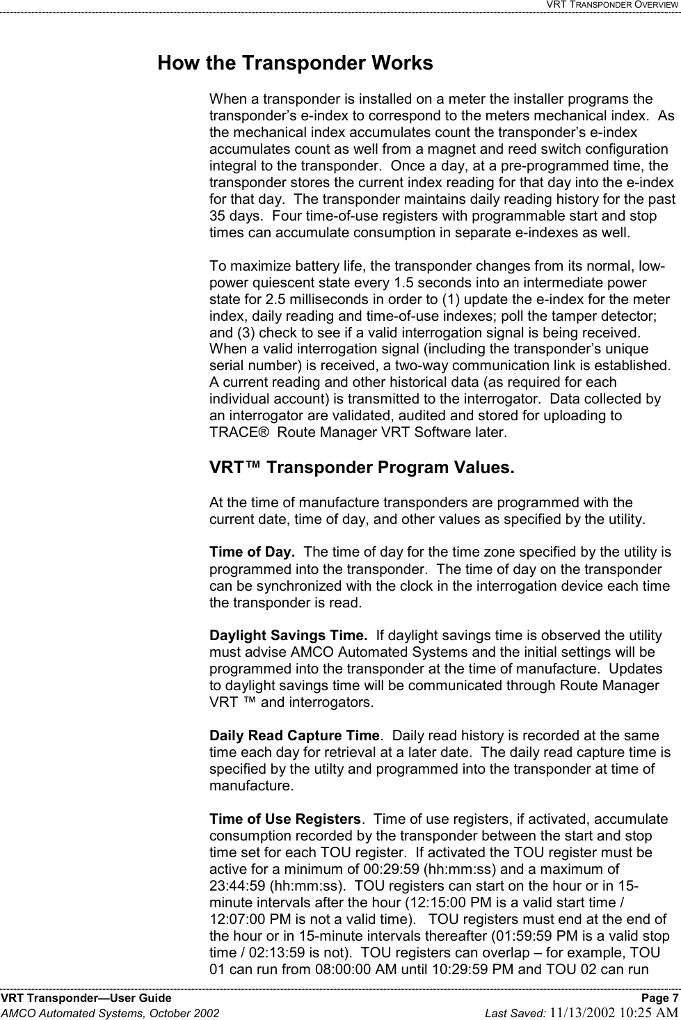
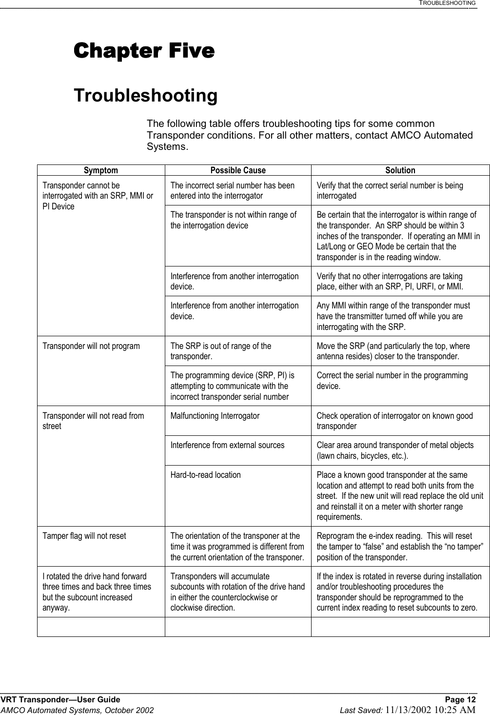
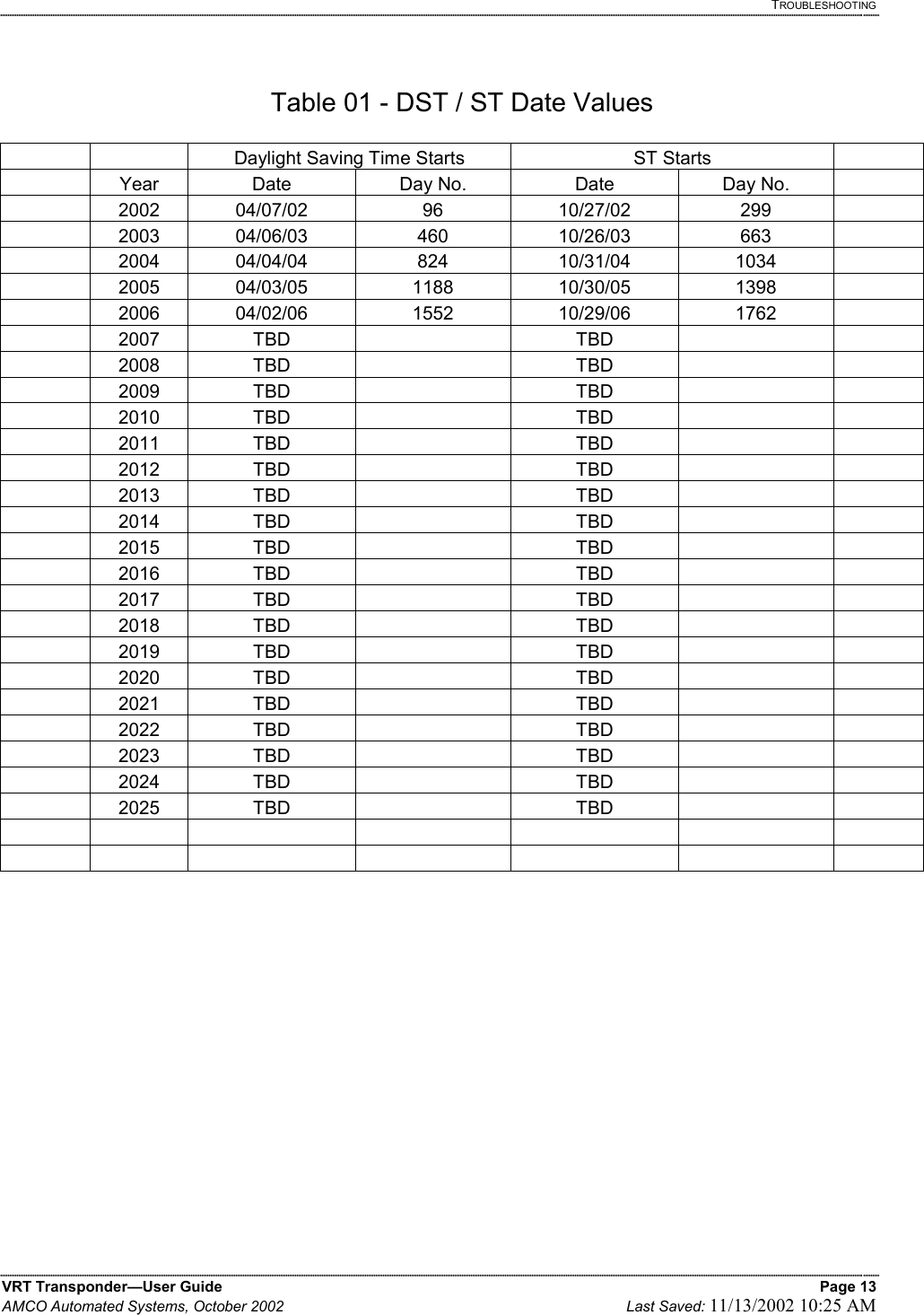
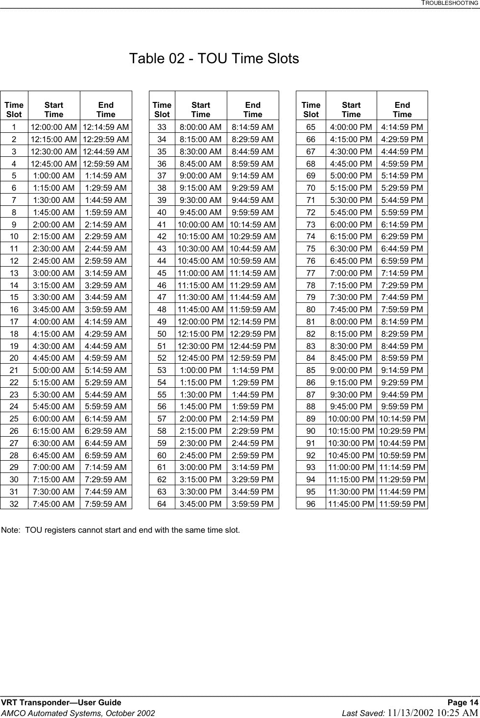
![VRT TRANSPONDER INSTALLATION & PROGRAMMING VRT Transponder—User Guide Page 11 AMCO Automated Systems, October 2002 Last Saved: 11/13/2002 10:25 AM This value is programmed at the factory and is retained in the event of a power interruption. The value can be reprogrammed if your requirements change. 5. Daily Read History The value in each Daily Read e-index is recorded at a pre-determined time every day and can be retrieved for up to 35 days. In the event of a power interruption these values are lost and cannot be retrieved. 6. Time of Use (TOU) e-index Parameters There can be different values for each TOU e-index. These values are programmed at the factory, but will be lost in the event of a power interruption. If your requirements change the TOU start and stop times can be reprogrammed at any time. 7. Time of Use (TOU) e-index Values The value in each TOU e-index accumulates as the mechanical index registers consumption. In the event of a power interruption the values in each TOU e-index is lost and cannot be recovered. 8. Index Drive Size / Subcounts per Revolution / Pre-Dividers The pre-divider value is programmed at time of manufacture and is dependant on the drive size of the meter/index being used with the transponder. This value can be reprogrammed by the utility if your requirements change. The pre-divider value resides in flash memory and it is not lost in the event of a power interruption. 9. Pressure Compensation Factor The pressure compensation factor programmed by the utility at time of installation is lost in the event of a power interruption, and must be reprogrammed. Compensation factors are unique for specific indexes and can be obtained by contacting AMCO Automated Systems’ Customer Service Department at (304) 757-3300. 10. Next Daylight Saving Time Day Number The transponder’s internal clock will automatically switch to daylight saving time on the date represented by the value entered into this field. The value must represent a future date. Please refer to table [TABLE 01] for a list of valid entries. This value is programmed at the factory for the next valid date after it is shipped, but must be updated by the utility for subsequent periods. In the event of a power interruption the value is retained. 11. Next Standard Time Number The transponder’s internal clock will automatically switch to standard time on the date represented by the value entered into this field. The value must represent a future date. Please refer to table [TABLE 01] for a list of valid entries. This value is programmed at the factory for the next valid date after it is shipped, but must be updated by the utility for subsequent periods. In the event of a power interruption the value is retained.](https://usermanual.wiki/Elster-Solutions/VRT01/User-Guide-285689-Page-15.png)