Elster Solutions VRT01 VRT Residential Gas Transponder User Manual CERTIFICATE OF COMPLIANCE
Elster Solutions, LLC VRT Residential Gas Transponder CERTIFICATE OF COMPLIANCE
Users Manual Revised

Rhein Tech Laboratories AMCO Automated Systems
360 Herndon Parkway
Suite 1400
VRT Residential Gas Transponder
FCC ID: G8JVRT01
Herndon, VA 20170 FCC Part 15.231
http://www.rheintech.com RTL WO# 2002187
Page 21 of 27
APPENDIX H: MANUAL
Please see the following pages.

U
U
US
S
SE
E
ER
R
R
G
G
GU
U
UI
I
ID
D
DE
E
E
TRACE ™
V
VR
RT
T
T
Tr
ra
an
ns
sp
po
on
nd
de
er
r
Copyright Acknowledgements
The contents of this document are the property of AMCO
Automated Systems and are copyrighted. All rights reserved.
Any reproduction, in whole or in part, is strictly prohibited. For
additional copies of this document, please contact:
AMCO Automated Systems
107 Erskine Lane
Scott Depot, WV 25560
Phone 304-757-3300 Fax 304-757-3388
The information contained herein has been carefully checked
and is believed to be accurate; however, no responsibility is
assumed for inaccuracies. AMCO Automated Systems reserves
the right to make changes without prior notice. This document is
not covered by any warranty either expressed or implied. Any
correction, comments or additions to the contents of this
document should be directed to AMCO Automated Systems at
the above address.
Copyright 2002 AMCO Automated Systems. Printed in USA.
TRACE, Universal RF Interface, URFI, Mini Mobile Interrogator,
ReadIt and TICS are trademarks of AMCO Automated Systems.
All rights reserved.
MS-DOS, IBM and MicroPalm are registered trademarks of their
respective owners.
FCC Compliance
The TRACE VRT Transponder™ has been type accepted by the
Federal Communications Commission under Part 15C, low
power communication device transmitter. FCC ID: G8JVRT01
This device complies with Part 15 rules. Operation is subject to
the following conditions:
1. This device may not cause harmful interference, and
2. This device must accept any interference received, including
interference that may cause undesired operation.
This equipment has been tested and found to comply with the
limits for a Class B digital device, pursuant to part 15 of the FCC
Rules. These limits are designed to provide reasonable
protection against harmful interference in a residential
installation. This equipment generates, uses and can radiate
radio frequency energy, and if not installed and used in
accordance with the instructions, may cause harmful interference
to radio communications. However, there is no guarantee that
interference will not occur in a particular installation. If this
equipment does cause harmful interference to radio or television
reception, which can be determined by turning the equipment off
and on, the user is encouraged to try to correct the interference
by one or more of the following measures:
• Reorient or relocate the receiving antenna.
• Increase the separation distance between the
equipment and receiver.
• Connect the equipment into an outlet on a circuit
different from that to which the receiver is
connected.
• Consult the dealer or an experience radio/TV
technician for help.
Changes or modifications not expressly approved by AMCO
Automated Systems could void the user’s authority to operate
the equipment.

T
ABLE OF CONTENTS
VRT Transponder—User Guide Page 1
AMCO Automated Systems, October 2002 Last Saved: 11/13/2002 10:25 AM
Transponder
Manual and Installation Guide
Table of Contents
Chapter One—Introduction................................................................................. 2
About this Document ....................................................................................... 2
Audience ................................................................................................... 2
Conventions .............................................................................................. 2
Chapter Two—Automated Meter Reading Overview........................................ 3
Basic AMR Components ................................................................................. 3
TRACE AMR System Overview ...................................................................... 4
Chapter Three—VRT Transponder Overview.................................................... 6
VRT Transponder and Components ............................................................... 6
How the VRT Transponder Works .................................................................. 7
Specifications .................................................................................................. 8
Chapter Four—VRT Transponder Operation .................................................... 9
Chapter Five—Troubleshooting ....................................................................... 12

I
NTRODUCTION
VRT Transponder—User Guide Page 2
AMCO Automated Systems, October 2002 Last Saved: 11/13/2002 10:25 AM
Chapter One
Chapter OneChapter One
Chapter One
Introduction
The TRACE® VRT Transponder is the heart of AMCO Automated
Systems’ portfolio of products for automated meter reading (AMR).
About this Document
The Transponder manual and installation Guide provides instructions for
installing and troubleshooting transponders. It also includes an overview
of both AMR in general and TRACE technology in particular.
Audience
This document is designed for utility industry meter readers and
supervisory staff. In order to establish appropriate levels of detail for the
material, this document assumes the following:
The user is proficient in reading meters of the type currently
compatible with TRACE transponders and possesses all the skills
necessary to conduct meter reading by conventional means.
The user has little or no prior expertise in the TRACE AMR
technology.
The user is familiar with common data entry devices and techniques.
Conventions
In the interest of brevity and simplicity, this document uses the following
conventions:
Additional information relevant to a given instruction step may be
shown in one of three ways:
1. A bulleted item covers “how-to” and verification information.
2. An italicized NOTE contains relevant background information.
3. An italicized and bolded CAUTION contains information
important to the safety of either the user or the equipment.
Where reference to other parties is made, the generic masculine
pronouns (he, his, him) are used. This is no way reflects bias or
gender discrimination in any manner related to the users, publishers
or authors of this document.
AMR OVERVIEW
VRT Transponder—User Guide Page 3
AMCO Automated Systems, October 2002 Last Saved: 11/13/2002 10:25 AM
Chapter Two
Chapter TwoChapter Two
Chapter Two
Automated Meter Reading Overview
The TRACE system uses radio frequency (RF) signals to allow utility
personnel to read meters from a distance while the reader is in motion.
This technology is called automated meter reading (AMR). This
technology greatly increases the speed at which routes can be covered
with a high degree of accuracy.
Basic AMR Components
An automated meter reading system requires the following basic
components:
Transponder—The transponder Interfaces with meter index
mechanics, translates index reading into digital signals to capture
data from meter, receives commands from an interrogator and
transmits meter data.
Interrogator—At its simplest, the interrogator remotely reads meter
data transmitted by transponders. At more sophisticated levels an
interrogator may also program transponders, store route data, “wake
up” transponders, verify transponder conditions and data and set
meter coordinates, among other functions.
Antennas—Both the transponder and the interrogator use antennas
to broadcast and receive RF signals. The transponder’s antenna is
typically located on the circuit board inside the transponder case.
Some interrogators use external antennas (as shown in the
illustration below), one for transmitting and one for receiving. Many
handheld interrogators use a single antenna for both transmitting and
receiving (antenna may be internal or external).
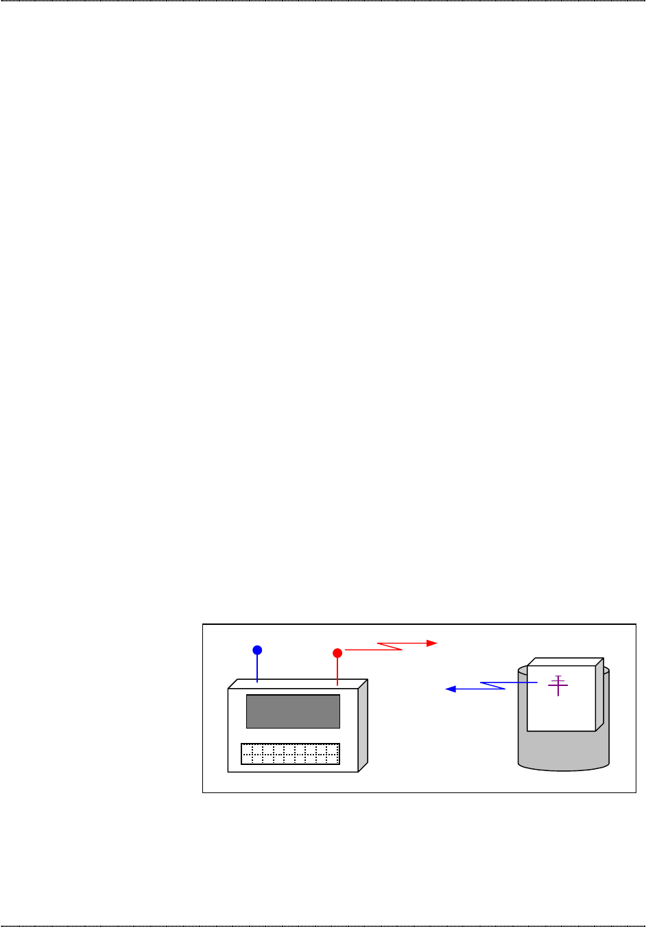
Transponder
METER
The interrogator sends out an RF signal to the desired transponders. Upon receiving an authorized
command the transponder transmits its stored meter data.
1234 ABC 864
234 Maple Drive
Interrogator
Interrogator transmits commands
& queries to transponder(s)
Transponder transmits
meter data to the
interrogator’s receiver
TRACE SYSTEM OVERVIEW
VRT Transponder—User Guide Page 4
AMCO Automated Systems, October 2002 Last Saved: 11/13/2002 10:25 AM
The TRACE AMR System Overview
In addition to standard automated meter reading functions, AMCO’s
TRACE system portfolio of products permits the remote recording of
tamper conditions and linking of meter latitude and longitude data using
a Global Positioning Satellite (GPS) system. With the optional Vehicle
Interactive Display, TRACE makes driver-to-meter orientation more
intuitive and efficient.
TRACE interrogators transmit at 451.35 MHz and receive transponder
messages at 415 MHz. (Transponders transmit between 414.5 and 415
MHz and receive at 451.35 MHz.)
Trace transponders, normally asleep, “wake up” and listen for an
interrogation signal once every second. Only if a transponder hears its
unique serial number will it transmit data back to the interrogation device,
and then it goes back to sleep.
How the TRACE System Works
Utility personnel no longer have to walk up to each meter, look at its
index and record its reading. Once transponders are installed on meters
and programmed, meter readers simply walk or drive down each street in
the route allowing the TRACE interrogator to request and record meter
data automatically.
Acquisition of meter information begins with the transponder where data
is stored continuously for later retrieval and moves to the interrogator
upon command. The acquired data from a given route can be transferred
to a host computer via floppy disk for processing.
The information acquisition, storage and handling process includes
several basic elements:
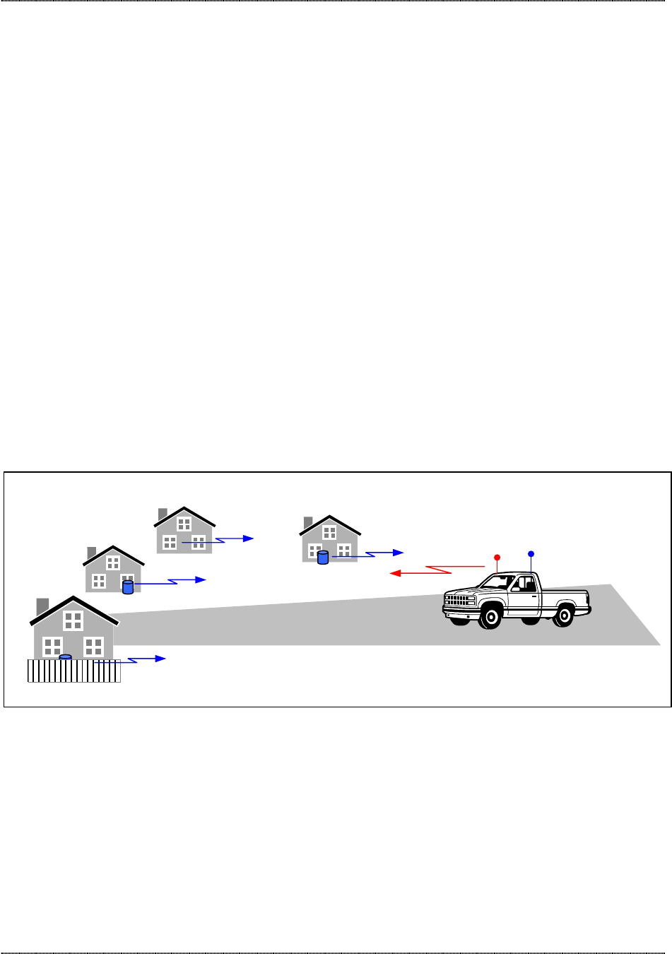
SN 1111 Read 208…
SN 2222 Read 943…
MMI
Equipped
SN 3333 Read 510…
SN 4444 Read 1031…
TRANSMIT
RECEIVE
The interrogator addresses each transponder in the interrogation window individually. When the transponder “hears” its serial number and proper authorization, it
transmits the current meter data. The TRACE system’s frequency band allows remote reading of transponders even through walls and fences.

TRACE SYSTEM OVERVIEW
VRT Transponder—User Guide Page 5
AMCO Automated Systems, October 2002 Last Saved: 11/13/2002 10:25 AM
Meter interface. Using a mechanical-to-digital interface, the TRACE
transponder senses the output from the index of a utility meter, translates
this into electronic form and stores it in the transponder’s memory.
Transponder data acquisition. The transponder is programmed with a
unique serial number at the time of manufacture. Upon installation on a
meter, the current (or baseline) meter index reading is also programmed
into the transponder’s memory. As the meter reading advances it
automatically updates transponder memory. The transponder also
records changes to the tamper detection sensor.
Compensation factor. For TRACE transponders using firmware
Version 9 or higher, a compensation factor can also be programmed into
the transponder memory ensuring the transponder readings match the
compensated mechanical index reading.
Route information loading. Route data includes meter account number,
address and latitude/longitude coordinates (when available), and
transponder serial number. This information, along with Guide and Start
files, is downloaded to the interrogator prior to commencing automated
meter reading. By also tracking the vehicle or interrogator’s coordinates,
a GPS-equipped system determines which transponders in the route
should lie within range at any given time and transmits those serial
numbers requesting meter data.
Interrogation. Once placed in an interrogation mode by the meter
reader, the TRACE interrogator transmits serial number(s) of the desired
transponder(s) along with a command requesting the contents of each
transponder’s memory. Transponders are selected for reading on the
basis of route and meter location information stored in the interrogator
and presence of the transponder within range of the interrogator.
Route data processing. Meter data from transponders is stored in the
interrogator’s memory and can be transferred to the utility’s host
computer for processing
VRT TRANSPONDER OVERVIEW
VRT Transponder—User Guide Page 6
AMCO Automated Systems, October 2002 Last Saved: 11/13/2002 10:25 AM
Chapter Three
Chapter ThreeChapter Three
Chapter Three
VRT Transponder Overview
The TRACE VRT Gas Transponder is designed for use with most
residential and commercial diaphragm meters from American Meter,
Equimeter/Invensys®, and Sprague/Schlumberger®. The transponder
can be programmed to work with a fixed factor, pressure-compensating
index. The transponder maintains the current time and date, which are
used to record real-time data for retrieval as required during the normal
read cycle. In addition to maintaining an electronic index (e-index)
reading that corresponds to the meter index reading, the transponder:
• Stores 35 daily index readings in separate e-indexes recorded at the
start of the utility day.
• Maintains up to four time-of-use (TOU) e-indexes that each have
programmable start and stop times.
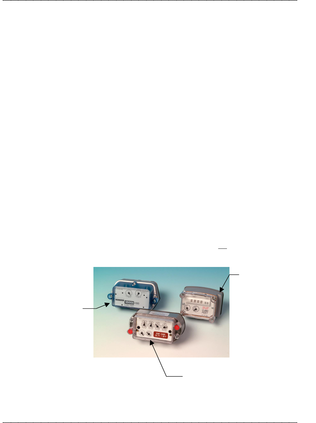
VRT Transponder and Components
The transponder consists of a high impact plastic housing with rubber
gasket; RF transmitter; receiver; tamper switch; transmit and receive
antennas; battery, and various electronic components.
The transponder is shipped with mounting hardware.
The meter’s existing index and index cover are attached to the
transponder. The index and index cover are not shipped with the
standard transponder, but in some cases may be purchased separately.
Sprague/Schlumberger
®
Equimeter/Invensys®
American Meter

VRT TRANSPONDER OVERVIEW
VRT Transponder—User Guide Page 7
AMCO Automated Systems, October 2002 Last Saved: 11/13/2002 10:25 AM
How the Transponder Works
When a transponder is installed on a meter the installer programs the
transponder’s e-index to correspond to the meters mechanical index. As
the mechanical index accumulates count the transponder’s e-index
accumulates count as well from a magnet and reed switch configuration
integral to the transponder. Once a day, at a pre-programmed time, the
transponder stores the current index reading for that day into the e-index
for that day. The transponder maintains daily reading history for the past
35 days. Four time-of-use registers with programmable start and stop
times can accumulate consumption in separate e-indexes as well.
To maximize battery life, the transponder changes from its normal, low-
power quiescent state every 1.5 seconds into an intermediate power
state for 2.5 milliseconds in order to (1) update the e-index for the meter
index, daily reading and time-of-use indexes; poll the tamper detector;
and (3) check to see if a valid interrogation signal is being received.
When a valid interrogation signal (including the transponder’s unique
serial number) is received, a two-way communication link is established.
A current reading and other historical data (as required for each
individual account) is transmitted to the interrogator. Data collected by
an interrogator are validated, audited and stored for uploading to
TRACE® Route Manager VRT Software later.
VRT™ Transponder Program Values.
At the time of manufacture transponders are programmed with the
current date, time of day, and other values as specified by the utility.
Time of Day. The time of day for the time zone specified by the utility is
programmed into the transponder. The time of day on the transponder
can be synchronized with the clock in the interrogation device each time
the transponder is read.
Daylight Savings Time. If daylight savings time is observed the utility
must advise AMCO Automated Systems and the initial settings will be
programmed into the transponder at the time of manufacture. Updates
to daylight savings time will be communicated through Route Manager
VRT ™ and interrogators.
Daily Read Capture Time. Daily read history is recorded at the same
time each day for retrieval at a later date. The daily read capture time is
specified by the utilty and programmed into the transponder at time of
manufacture.
Time of Use Registers. Time of use registers, if activated, accumulate
consumption recorded by the transponder between the start and stop
time set for each TOU register. If activated the TOU register must be
active for a minimum of 00:29:59 (hh:mm:ss) and a maximum of
23:44:59 (hh:mm:ss). TOU registers can start on the hour or in 15-
minute intervals after the hour (12:15:00 PM is a valid start time /
12:07:00 PM is not a valid time). TOU registers must end at the end of
the hour or in 15-minute intervals thereafter (01:59:59 PM is a valid stop
time / 02:13:59 is not). TOU registers can overlap – for example, TOU
01 can run from 08:00:00 AM until 10:29:59 PM and TOU 02 can run

VRT TRANSPONDER OVERVIEW
VRT Transponder—User Guide Page 8
AMCO Automated Systems, October 2002 Last Saved: 11/13/2002 10:25 AM
from 10:15:00 AM until 2:29:59 PM. TOU registers can span midnight –
a start time of 08:00:00 PM with a stop time of 01:59:59 AM is valid.
Index Drive Size / Subcounts per Revolution / Pre-Dividers. The
number of subcounts recorded with each revolution of the drive dial on 1-
ft3 and 2-ft3 indexes is one. A 1-ft3 index requires 100 revolutions to yield
100 ft3 and a 2-ft3 index requires 50 revolutions to yield 100 ft3.
Therefore, the pre-divider for a 1-ft3 index is 100 and for a 2-ft3 index it is
50.
Pressure Compensation Factor. When a transponder is used in
conjunction with a pressure compensated index a compensation factor
can be programmed into the transponder memory by the utility at the
time of installation. This instructs the transponder’s microprocessor to
compute adjustments to the meter reading as needed. Compensation
factors are unique for specific indexes and can be obtained by contacting
AMCO Automated Systems’ Customer Service Department at (304) 757-
3300.
Specifications
The following table shows the VRT Transponder specifications:
Power One (1) lithium – Thionyl chloride 275 amp-hours; 20 years calculated life
under normal working conditions. The battery can be easily replaced in the
field.
FCC Compliance Part 15, Subpart C: a user license is not required (FCC ID G8JVRT01)
RF Transmitter 414.5 MHz, +0.5, -1.0 MHz; 4,000 uV/m @ 3m.
RF Receiver 451.35 MHz; -70 dBm sensitivity
Materials • Housing: high-impact plastic, weatherproof, UV protected for outdoor
installation.
• Circuit-card assembly: conformal-coated
• Corrosion–protected external-housing screws
Operating Temperature
Range -22°F to 158°F (-30°C to 70°C)
Storage Temperature
Range
-40 °F to 185°F (-40°C to 85°C)
Humidity 5-95% Relative (non-condensing)
Weight 6 oz. Excluding index and index cover.
Serial Numbers Up to eight digits, starting at 6500000

VRT TRANSPONDER INSTALLATION & PROGRAMMING
VRT Transponder—User Guide Page 9
AMCO Automated Systems, October 2002 Last Saved: 11/13/2002 10:25 AM
Chapter Four
Chapter FourChapter Four
Chapter Four
Transponder Installation & Programming
Installation
1. Prior to removing the existing index and index cover, verify that the
transponder style is compatible with the meter style.
2. Verify that the battery is properly seated, and that the battery wires
are flush to the left side of the transponder wall (facing the rear of the
transponder). Note: When transporting transponders to the field for
installation please take care not to jar the housing and dislodge the
battery from the bracket.
3. Verify that the transponder is in good working order by querying the
transponder for the meter reading using an SRP, PI, or any other
appropriate interrogation device.
4. If the transponder is in good working order, remove the existing
index and index cover from the meter. Remove the gasket and any
adhesive material from the meter – a scraper or putty knife is
recommended for this task.
5. Using the self-tapping index screws provided, mount existing index
to the transponder, verifying that the index wriggler is properly mated
with the transponder wriggler.
6. Mechanical Check
a. Once the index is attached to the transponder, perform a quick
spin test to verify that the index rotates freely and without
resistance. If the index is rotated 3 times in the clockwise
direction, be sure to rotate it 3 times in the counter-clockwise
direction to assure that no additional subcounts or counts are
inadvertently placed on the mechanical index. Subcounts added
to the e-index during this procedure will be cleared when the
transponder is programmed to the mechanical index reading.
7. Sub-Count Check
a. Rotate the transponder wriggler such that the drive dial is in the
12 o’clock position.
b. Read the transponder subcounts using an SRP, making note of
the subcount value.
c. While facing the index rotate the drive dial 3 times in the counter-
clockwise direction, stopping at the 12 o’clock position.
d. Read the transponder subcounts using an SRP, making note of
the new subcount value. The new subcount value should read 3
subcounts higher than the original reading. If the new subcount
value is less than the original subcount value, please consider

VRT TRANSPONDER INSTALLATION & PROGRAMMING
VRT Transponder—User Guide Page 10
AMCO Automated Systems, October 2002 Last Saved: 11/13/2002 10:25 AM
the possibility that the subcounts rolled over. If the values do not
meet to your expectations, repeat from Step 7a.
8. Mounting Transponder
a. Visually align transponder wriggler with meter wriggler.
b. Mate the transponder wriggler with the meter wriggler. (Picture
here, all three TP styles)
9. Holding the transponder on the meter, place the index cover onto the
transponder, verifying that the index cover weep holes are at the
bottom.
10. Secure transponder to the meter using the mounting bolts provided.
The recommended torque range is 14-26-in-lbs.
11. Install the tamper seals into the index cover receptacles.
12. Remove the auxiliary label from the transponder and attach it to your
field order.
Programming
Note: Transponders not installed on meters may accumulate sub-
counts during shipping. Sub-counts are automatically reset to zero
when the current e-index reading is programmed. With the exception of
transponders delivered on meters, all transponders (even those mated
with indexes set at 0000) should be programmed after installation on the
meter to confirm that the subcount is set at zero when the transponder is
placed in service.
The tamper flag is set to “false” or “not tampered” when the transponder
is programmed. The orientation of the transponder at the time that it is
programmed will be the “not tampered” orientation for future reference. If
a transponder is mounted on a meter which is subsequently installed in a
different orientation, you may need to reprogram the transponder to
remove it from a tampered condition.
Please refer to the SRP manual for programming instructions, if required.
1. Index Reading
Program the transponder’s e-index value to the value of the
mechanical index.
2. Current Date
This value is programmed at the factory, but will be lost in the event
of a power interruption. If necessary, program the transponder with
the current date.
3. Current Time
This value is programmed at the factory, but will be lost in the event
of a power interruption. If necessary, program the transponder with
the current time.
4. Daily Read Capture Time

VRT TRANSPONDER INSTALLATION & PROGRAMMING
VRT Transponder—User Guide Page 11
AMCO Automated Systems, October 2002 Last Saved: 11/13/2002 10:25 AM
This value is programmed at the factory and is retained in the event
of a power interruption. The value can be reprogrammed if your
requirements change.
5. Daily Read History
The value in each Daily Read e-index is recorded at a pre-
determined time every day and can be retrieved for up to 35 days. In
the event of a power interruption these values are lost and cannot be
retrieved.
6. Time of Use (TOU) e-index Parameters
There can be different values for each TOU e-index. These values
are programmed at the factory, but will be lost in the event of a
power interruption. If your requirements change the TOU start and
stop times can be reprogrammed at any time.
7. Time of Use (TOU) e-index Values
The value in each TOU e-index accumulates as the mechanical
index registers consumption. In the event of a power interruption the
values in each TOU e-index is lost and cannot be recovered.
8. Index Drive Size / Subcounts per Revolution / Pre-Dividers
The pre-divider value is programmed at time of manufacture and is
dependant on the drive size of the meter/index being used with the
transponder. This value can be reprogrammed by the utility if your
requirements change. The pre-divider value resides in flash memory
and it is not lost in the event of a power interruption.
9. Pressure Compensation Factor
The pressure compensation factor programmed by the utility at time
of installation is lost in the event of a power interruption, and must be
reprogrammed. Compensation factors are unique for specific
indexes and can be obtained by contacting AMCO Automated
Systems’ Customer Service Department at (304) 757-3300.
10. Next Daylight Saving Time Day Number
The transponder’s internal clock will automatically switch to daylight
saving time on the date represented by the value entered into this
field. The value must represent a future date. Please refer to table
[TABLE 01] for a list of valid entries. This value is programmed at
the factory for the next valid date after it is shipped, but must be
updated by the utility for subsequent periods. In the event of a
power interruption the value is retained.
11. Next Standard Time Number
The transponder’s internal clock will automatically switch to standard
time on the date represented by the value entered into this field. The
value must represent a future date. Please refer to table [TABLE 01]
for a list of valid entries. This value is programmed at the factory for
the next valid date after it is shipped, but must be updated by the
utility for subsequent periods. In the event of a power interruption
the value is retained.

T
ROUBLESHOOTING
VRT Transponder—User Guide Page 12
AMCO Automated Systems, October 2002 Last Saved: 11/13/2002 10:25 AM
Chapter Five
Chapter FiveChapter Five
Chapter Five
Troubleshooting
The following table offers troubleshooting tips for some common
Transponder conditions. For all other matters, contact AMCO Automated
Systems.
Symptom Possible Cause Solution
The incorrect serial number has been
entered into the interrogator
Verify that the correct serial number is being
interrogated
The transponder is not within range of
the interrogation device
Be certain that the interrogator is within range of
the transponder. An SRP should be within 3
inches of the transponder. If operating an MMI in
Lat/Long or GEO Mode be certain that the
transponder is in the reading window.
Interference from another interrogation
device.
Verify that no other interrogations are taking
place, either with an SRP, PI, URFI, or MMI.
Transponder cannot be
interrogated with an SRP, MMI or
PI Device
Interference from another interrogation
device.
Any MMI within range of the transponder must
have the transmitter turned off while you are
interrogating with the SRP.
The SRP is out of range of the
transponder.
Move the SRP (and particularly the top, where
antenna resides) closer to the transponder.
Transponder will not program
The programming device (SRP, PI) is
attempting to communicate with the
incorrect transponder serial number
Correct the serial number in the programming
device.
Malfunctioning Interrogator Check operation of interrogator on known good
transponder
Interference from external sources Clear area around transponder of metal objects
(lawn chairs, bicycles, etc.).
Transponder will not read from
street
Hard-to-read location Place a known good transponder at the same
location and attempt to read both units from the
street. If the new unit will read replace the old unit
and reinstall it on a meter with shorter range
requirements.
Tamper flag will not reset The orientation of the transponer at the
time it was programmed is different from
the current orientation of the transponer.
Reprogram the e-index reading. This will reset
the tamper to “false” and establish the “no tamper”
position of the transponder.
I rotated the drive hand forward
three times and back three times
but the subcount increased
anyway.
Transponders will accumulate
subcounts with rotation of the drive hand
in either the counterclockwise or
clockwise direction.
If the index is rotated in reverse during installation
and/or troubleshooting procedures the
transponder should be reprogrammed to the
current index reading to reset subcounts to zero.

T
ROUBLESHOOTING
VRT Transponder—User Guide Page 13
AMCO Automated Systems, October 2002 Last Saved: 11/13/2002 10:25 AM
Table 01 - DST / ST Date Values
Daylight Saving Time Starts ST Starts
Year Date Day No. Date Day No.
2002 04/07/02 96 10/27/02 299
2003 04/06/03 460 10/26/03 663
2004 04/04/04 824 10/31/04 1034
2005 04/03/05 1188 10/30/05 1398
2006 04/02/06 1552 10/29/06 1762
2007 TBD TBD
2008 TBD TBD
2009 TBD TBD
2010 TBD TBD
2011 TBD TBD
2012 TBD TBD
2013 TBD TBD
2014 TBD TBD
2015 TBD TBD
2016 TBD TBD
2017 TBD TBD
2018 TBD TBD
2019 TBD TBD
2020 TBD TBD
2021 TBD TBD
2022 TBD TBD
2023 TBD TBD
2024 TBD TBD
2025 TBD TBD

T
ROUBLESHOOTING
VRT Transponder—User Guide Page 14
AMCO Automated Systems, October 2002 Last Saved: 11/13/2002 10:25 AM
Table 02 - TOU Time Slots
Time
Slot
Start
Time
End
Time
Time
Slot
Start
Time
End
Time
Time
Slot
Start
Time
End
Time
1 12:00:00 AM 12:14:59 AM 33 8:00:00 AM 8:14:59 AM 65 4:00:00 PM 4:14:59 PM
2 12:15:00 AM 12:29:59 AM 34 8:15:00 AM 8:29:59 AM 66 4:15:00 PM 4:29:59 PM
3 12:30:00 AM 12:44:59 AM 35 8:30:00 AM 8:44:59 AM 67 4:30:00 PM 4:44:59 PM
4 12:45:00 AM 12:59:59 AM 36 8:45:00 AM 8:59:59 AM 68 4:45:00 PM 4:59:59 PM
5 1:00:00 AM 1:14:59 AM 37 9:00:00 AM 9:14:59 AM 69 5:00:00 PM 5:14:59 PM
6 1:15:00 AM 1:29:59 AM 38 9:15:00 AM 9:29:59 AM 70 5:15:00 PM 5:29:59 PM
7 1:30:00 AM 1:44:59 AM 39 9:30:00 AM 9:44:59 AM 71 5:30:00 PM 5:44:59 PM
8 1:45:00 AM 1:59:59 AM 40 9:45:00 AM 9:59:59 AM 72 5:45:00 PM 5:59:59 PM
9 2:00:00 AM 2:14:59 AM 41 10:00:00 AM 10:14:59 AM 73 6:00:00 PM 6:14:59 PM
10 2:15:00 AM 2:29:59 AM 42 10:15:00 AM 10:29:59 AM 74 6:15:00 PM 6:29:59 PM
11 2:30:00 AM 2:44:59 AM 43 10:30:00 AM 10:44:59 AM 75 6:30:00 PM 6:44:59 PM
12 2:45:00 AM 2:59:59 AM 44 10:45:00 AM 10:59:59 AM 76 6:45:00 PM 6:59:59 PM
13 3:00:00 AM 3:14:59 AM 45 11:00:00 AM 11:14:59 AM 77 7:00:00 PM 7:14:59 PM
14 3:15:00 AM 3:29:59 AM 46 11:15:00 AM 11:29:59 AM 78 7:15:00 PM 7:29:59 PM
15 3:30:00 AM 3:44:59 AM 47 11:30:00 AM 11:44:59 AM 79 7:30:00 PM 7:44:59 PM
16 3:45:00 AM 3:59:59 AM 48 11:45:00 AM 11:59:59 AM 80 7:45:00 PM 7:59:59 PM
17 4:00:00 AM 4:14:59 AM 49 12:00:00 PM 12:14:59 PM 81 8:00:00 PM 8:14:59 PM
18 4:15:00 AM 4:29:59 AM 50 12:15:00 PM 12:29:59 PM 82 8:15:00 PM 8:29:59 PM
19 4:30:00 AM 4:44:59 AM 51 12:30:00 PM 12:44:59 PM 83 8:30:00 PM 8:44:59 PM
20 4:45:00 AM 4:59:59 AM 52 12:45:00 PM 12:59:59 PM 84 8:45:00 PM 8:59:59 PM
21 5:00:00 AM 5:14:59 AM 53 1:00:00 PM 1:14:59 PM 85 9:00:00 PM 9:14:59 PM
22 5:15:00 AM 5:29:59 AM 54 1:15:00 PM 1:29:59 PM 86 9:15:00 PM 9:29:59 PM
23 5:30:00 AM 5:44:59 AM 55 1:30:00 PM 1:44:59 PM 87 9:30:00 PM 9:44:59 PM
24 5:45:00 AM 5:59:59 AM 56 1:45:00 PM 1:59:59 PM 88 9:45:00 PM 9:59:59 PM
25 6:00:00 AM 6:14:59 AM 57 2:00:00 PM 2:14:59 PM 89 10:00:00 PM 10:14:59 PM
26 6:15:00 AM 6:29:59 AM 58 2:15:00 PM 2:29:59 PM 90 10:15:00 PM 10:29:59 PM
27 6:30:00 AM 6:44:59 AM 59 2:30:00 PM 2:44:59 PM 91 10:30:00 PM 10:44:59 PM
28 6:45:00 AM 6:59:59 AM 60 2:45:00 PM 2:59:59 PM 92 10:45:00 PM 10:59:59 PM
29 7:00:00 AM 7:14:59 AM 61 3:00:00 PM 3:14:59 PM 93 11:00:00 PM 11:14:59 PM
30 7:15:00 AM 7:29:59 AM 62 3:15:00 PM 3:29:59 PM 94 11:15:00 PM 11:29:59 PM
31 7:30:00 AM 7:44:59 AM 63 3:30:00 PM 3:44:59 PM 95 11:30:00 PM 11:44:59 PM
32 7:45:00 AM 7:59:59 AM 64 3:45:00 PM 3:59:59 PM 96 11:45:00 PM 11:59:59 PM
Note: TOU registers cannot start and end with the same time slot.