Elta Systems 2127 Radar User Manual ELM2127 userman 111909
Elta Systems Ltd. Radar ELM2127 userman 111909
UserManual.wiki
>
Elta Systems
>
2127 User Manual
manual
Navigation menu
Upload a User Manual
Namespaces
Wiki Guide
HTML
PDF
Info
Views
User Manual
Discussion / Help
Navigation
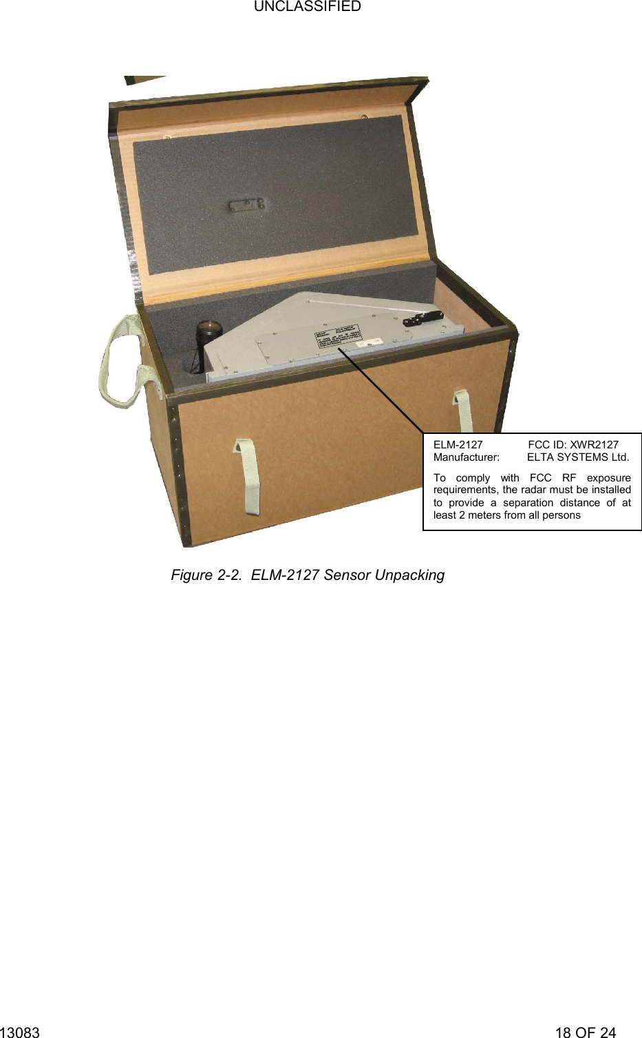
![UNCLASSIFIED 13083 17 OF 24 2.3 ELM-2127 DEPLOYMENT 2.3.1 Unpacking ELM-2127 Sensor To unpack ELM-2127 sensor, proceed as follows: ELM-2127 sensor radome is sensitive to mechanical damage. While moving the ELM-2127 sensor, verify radome does not come in contact with sharp or abrasive objects. Do not rest the ELM-2127 sensor with the radome facing down, on the radome corners or edges. Failure to comply may cause damage to ELM-2127 sensor radome. 1) Verify ELM-2127 storage box [1] is intact and without any visible damage. 2) Release ELM-2127 storage box locking strips [2] and open the box. 3) Using ELM-2127 sensor carrying handles, carefully remove ELM-2127 sensor (3) from the storage box. 4) Visually inspect ELM-2127 sensor and verify its exterior is intact and clear of dust or dirt. If required, clean it using soft dry cloth.](https://usermanual.wiki/Elta-Systems/2127/User-Guide-1205545-Page-17.png)
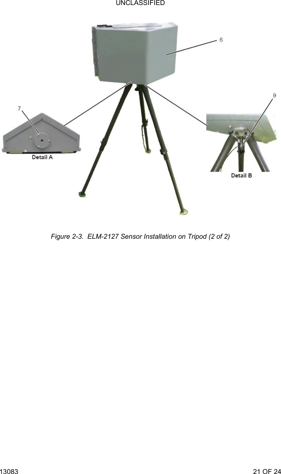
![UNCLASSIFIED 13083 19 OF 24 2.3.2 ELM-2127 Installation on Tripod To install ELM-2127 sensor on the tripod, proceed as follows (Figure 2-3): 1) Open tripod securing strip [1] and spread tripod legs. Verify leg top latches [2] are locked. 2) Release tripod legs latches [3] and adjust tripod legs [4] height. 3) Position the tripod and level it by adjusting legs height. Verify tripod level bubble [5] is positioned at the center of the circle in the leveling window. Verify three leg latches are properly locked before installing ELM-2127 sensor. Failure to comply may cause damage to ELM-2127 sensor. 4) Mount ELM-2127 sensor [6] on the tripod so that three protrusions [7] on the sensor mounting surface fit into three depressions [8] on the tripod. 5) Using securing screw [9], secure ELM-2127 sensor to tripod.](https://usermanual.wiki/Elta-Systems/2127/User-Guide-1205545-Page-19.png)

![UNCLASSIFIED 13083 23 OF 24 2.3.4 ELM-2127 Sensor Northing To align ELM-2127 sensor to required azimuth, proceed as follows (Figure 2-4): 1) Install telescope [1] on ELM-2127 sensor telescope base [2] and secure it using securing screw [3]. 2) Remove lens protective covers. 3) Aim the telescope an object in the horizon, whose azimuth is known. Use the carrying handles to move the ELM-2127 sensor or to adjust its direction. Do not apply any force on the telescope or radome. Failure to comply may cause damage to ELM-2127 sensor or telescope. 4) Record the ELM-2127 sensor azimuth for further use. Figure 2-4. Aligning ELM-2127 Sensor Azimuth](https://usermanual.wiki/Elta-Systems/2127/User-Guide-1205545-Page-23.png)
![UNCLASSIFIED 13083 24 OF 24 2.3.5 ELM-2127 Connecting to Tactical Center and Power To connect ELM-2127 sensor to the tactical center and power, proceed as follows (Figure 2-5): NOTE 1018E220-001 - includes two connectors: J1 - power and J2 - communication (using 1018E247-001 cable). The following description refers to 1018E220-001 configurations. 1) Connect cable power connector P1 to ELM-2127 sensor J1 [1]. 2) Connect cable communication connector P2 to ELM-2127 sensor J2 [2]. 3) Connect cable Ethernet connector (RJ45) to tactical center Ethernet connector. 4) Connect cable power wires to 24 VDC power source. Verify 24 VDC power source output is stable without interruption or power drops. Failure to comply may cause damage to the ELM-2127 sensor. Figure 2-5. Connecting ELM-2127 Sensor to Tactical Center and Power](https://usermanual.wiki/Elta-Systems/2127/User-Guide-1205545-Page-24.png)