Elta Systems 2127 Radar User Manual ELM2127 userman 111909
Elta Systems Ltd. Radar ELM2127 userman 111909
manual

ELTA SYSTEMS, LTD. - P.O.B. 330, ASHDOD 77102, ISRAEL - TEL. 972-8-8572410 - FAX. 972-8-8561872 - EMAIL: MARKET@ELTA.CO.IL
RESTRICTION ON USE, DUPLICATION, OR
DISCLOSURE OF PROPRIETARY INFORMATION
THIS DOCUMENT CONTAINS PROPRIETARY INFORMATION, WHICH IS
THE SOLE PROPERTY OF ELTA SYSTEMS LTD. THE DOCUMENT IS
SUBMITTED TO THE RECIPIENT FOR HIS USE ONLY. BY RECEIVING
THIS DOCUMENT, THE RECIPIENT UNDERTAKES NOT TO DUPLICATE
THE DOCUMENT OR TO DISCLOSE IN PART OF, OR THE WHOLE OF,
ANY OF THE INFORMATION CONTAINED HEREIN TO ANY THIRD
PARTY WITHOUT RECEIVING BEFORE HAND, WRITTEN PERMISSION
FROM THE SUBMITTING COMPANY.
UNCLASSIFIED
EL/M 2127
USER MANUAL
UNCLASSIFIED
13083 2 OF 24
TABLE OF CONTENTS
1.
GENERAL DESCRIPTION................................................................................2-3
1.1
SCOPE .............................................................................................................2-3
1.2
INTRODUCTION...............................................................................................2-3
1.3
ELM-2127 MAIN FEATURES............................................................................2-5
1.4
SYSTEM ARCHITECTURE...............................................................................2-6
1.4.1
ELM-2127 Sensor .............................................................................................2-7
1.4.2
Tactical Center..................................................................................................2-8
1.4.3
Remote C&C.....................................................................................................2-8
1.4.4
System Connections .........................................................................................2-8
1.5
ELM-2127 PHYSICAL DESCRIPTION..............................................................2-9
1.5.1
System Physical Description .............................................................................2-9
1.5.2
Sensor Physical Description............................................................................2-10
1.5.3
ELM-2127 Cable Physical Description ............................................................2-12
1.5.4
ELM-2127 Tripod Physical Description............................................................2-13
1.6
ELM-2127 MAIN CHARACTERISTICS ...........................................................2-14
CHAPTER 2
DEPLOYMENT...........................................................................................2-15
2.1
SCOPE ...........................................................................................................2-15
2.2
SENSOR LOCATION SELECTION.................................................................2-15
2.3
ELM-2127 DEPLOYMENT ..............................................................................2-17
2.3.1
Unpacking ELM-2127 Sensor..........................................................................2-17
2.3.2
ELM-2127 Installation on Tripod......................................................................2-19
2.3.3
ELM-2127 Installation on Pole.........................................................................2-22
2.3.4
ELM-2127 Sensor Northing.............................................................................2-23
2.3.5
ELM-2127 Connecting to Tactical Center and Power ......................................2-24
UNCLASSIFIED
13083 3 OF 24
1. GENERAL DESCRIPTION
1.1 SCOPE
This chapter provides general description of the ELM-2127 system and its main components.
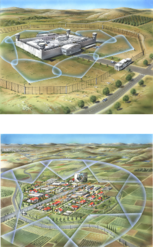
1.2 INTRODUCTION
The Smart Miniature Detection Radar (ELM-2127) is small ground surveillance radar used for anti-
intruder operations. It detects and tracks the intruder movements in and out of any fenced area
(Figure 1-1 and Figure 1-2) or selected zone such as: borders (terrorism, drug smuggling etc.), army
bases, power stations, prisons, mines, governmental buildings, nuclear facilities, airports, oil
reservoirs.
The ELM-2127 is tailored to the customer site type, terrain constraints, environmental conditions, type
of threats to guard from, nature of law enforcement roles and concept and many other parameters.
The ELM-2127 utilizes an advanced waveform with signal processing techniques for high resolution
and high probability of target detection, coupled with low radiated power.
The ELM-2127 low power consumption, small volume, and full solid state design enables deployment
in almost any area, terrain and weather conditions, while featuring high Mean Time between Failures
(MTBF).
The ELM-2127 is comprised of an RF transceiver module, digital receiver and signal processor,
antenna modules, and DC-DC converter.
Detected targets are displayed on a separate PC display. The radar display may be deployed at large
distance from the system via LAN or wireless network.
The ELM-2127 power is supplied by an external 24 VDC power source, converted internally to the
required power supply.
UNCLASSIFIED
13083 4 OF 24
Figure 1-1. ELM-2127 Deployment - Internal Surveillance (Example)
Figure 1-2. ELM-2127 Deployment - Perimeter Protection (Example)
UNCLASSIFIED
13083 5 OF 24
1.3 ELM-2127 MAIN FEATURES
High resolution pulse-Doppler radar operating in the upper X- frequency band.
Consists of two printed-patch array mono-pulse antennas. No moving parts; target area is
scanned using phased array techniques.
The phased array antennas divide the coverage area into discrete, smaller sectors. Each
antenna covers ±30° in azimuth providing overall coverage of 120° in azimuth and 10° in
elevation.
Low power dissipation.
Provides automatic detection and tracking for the alert phase. The system alerts that a
movement is detected and indicates the alert on a map.
Built in a compact case that may be installed on any building, fence, or tower and is easily
transportable (by light vehicle or carried by a single person).
Enables operation as stand-alone by local operator in a fixed installation or portable.
Enables integration with other systems via Ethernet or WLAN to a host system.
Operates in bad weather conditions. ELM-2127 performs well under adverse weather conditions:
rain, fog, high and low temperature extremes.
Classifies the detected target. Classification is usually done without operator assistance.
UNCLASSIFIED
13083 6 OF 24
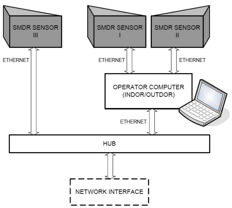
1.4 SYSTEM ARCHITECTURE
The ELM-2127 system consists of the following subunits:
Multiple ELM-2127 sensors - connected to operator computer (tactical center) or other systems
using Ethernet.
Operator indoor or outdoor post - based on PC or laptop computer with dedicated ELM-2127
application, providing ELM-2127 Human Machine Interface (HMI).
Remote Command & Control (C&C) interface via Ethernet communication.
NOTE
In the current application, only one sensor is connecter to
each tactical center.
Figure 1-3. ELM-2127 System Architecture
UNCLASSIFIED
13083 7 OF 24
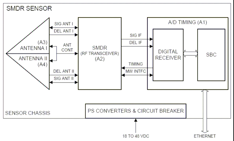
1.4.1 ELM-2127 Sensor
The ELM-2127 is composed of one or more sensors (Figure 1-4), connected using Ethernet to
operator post.
The ELM-2127 sensor consists of the following:
A/D Timing (A1) module - includes two main sections:
− Digital receiver - performs A/D conversion and digital reception.
− Single Board Computer - performs signal processing, communication with the tactical center
via Ethernet and sensor timing and control.
Two Antenna modules (A3, A4) - perform RF signal transmission and reception using phased
array technology. Each antenna provides sigma and delta channels for reception.
RF Transceiver module (A2) - generates RF signal for transmission, and during reception, down
converts RF signals to IF and sends them to A/D Timing module.
Power conversion module - DC to DC converters, which converts 24 VDC input power to power
supplies for sensor models.
Figure 1-4. ELM-2127 Sensor Block Diagram
UNCLASSIFIED
13083 8 OF 24
1.4.2 Tactical Center
The ELM-2127 application provides stand alone C&C Graphic User Interface (GUI) and tactical
display.
NOTE
The tactical center PC is also named Control and Display
Unit (CDU).
The C&C GUI provides the following functions:
Communication with the sensor
Sensor control
HW status monitoring and display.
The tactical display provides the following functions:
Background map (2D, 3D)
Raster and vector layers and user sketches objects (icons, lines, polygons, texts)
Scanning sector display
Detections display, including plots, tracks, zones (alarm zones, ignoring zones, etc.)
Data display, including clutter data, lines of sights, orientation global map.
1.4.3 Remote C&C
The ELM-2127 system can be controlled from distance via Ethernet communication.
The remote control supports control over several sensors, and radar networking.
NOTE
The current application is provided in stand alone
configuration.
1.4.4 System Connections
The power is supplied to the system from a 24 VDC power source.
The tactical center is connected to the ELM-2127 sensor via Ethernet, using LAN cable.
UNCLASSIFIED
13083 9 OF 24
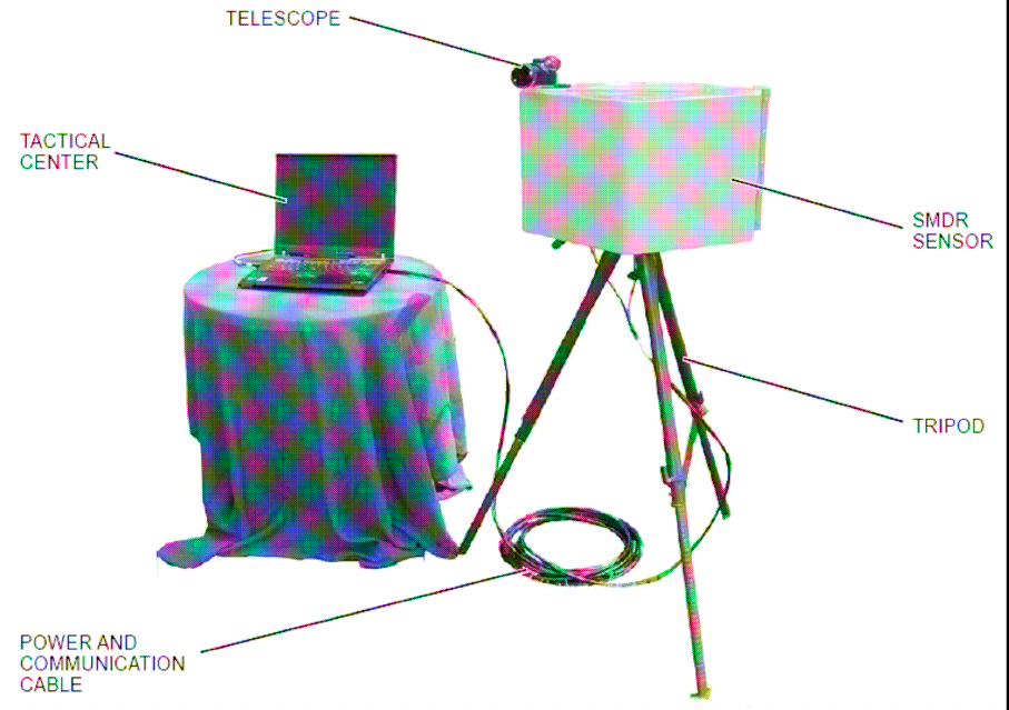
1.5 ELM-2127 PHYSICAL DESCRIPTION
1.5.1 System Physical Description
The ELM-2127 system (Figure 1-5) comprises the following units:
ELM-2127 sensor - installed on ELM-2127 tripod or stationary pole.
Tactical center - based on standard PC or laptop, with ELM-2127 dedicated applications.
Power and communications cable - provides 24 VDC power supply to ELM-2127 sensor and
communication between the sensor and the tactical center, via Ethernet.
Telescope - used for during operational deployment to set system azimuth relative to north.
Tripod - used for system deployment.
NOTE
In case that ELM-2127 sensor is installed on a stationary
pole, the tripod is not used.
Figure 1-5. ELM-2127 General View
UNCLASSIFIED
13083 10 OF 24
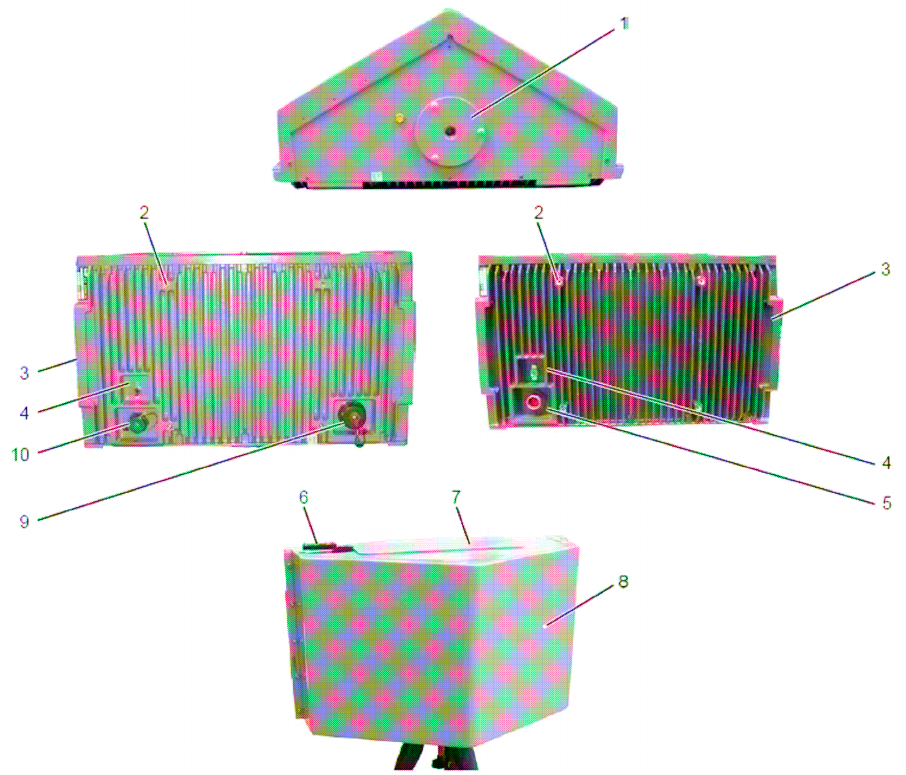
1.5.2 Sensor Physical Description
The ELM-2127 sensor (Figure 1-6) includes the radar transceiver, antennas and processing modules.
The ELM-2127 sensor has a single motherboard, which hosts all modules.
NOTE
The ELM-2127 mechanical design has two
configurations:
1018E170-001 - includes a single connector for
power and communication.
1018E220-001 - includes two connectors:
J1 - power and J2 - communication.
Figure 1-6. ELM-2127 Sensor Elements

UNCLASSIFIED
13083 11 OF 24
Table 1-1 details ELM-2127 senor elements.
Table 1-1. ELM-2127 Sensor Elements
No. Name Function
1 Tripod Mounting Thread Single-mounting thread for installation on tripod
2 Pole Mounting Threads Four-mounting threads for installation on pole (using
a mounting adaptor)
3 Carrying Handle Use to carry the ELM-2127 sensor.
4 ON/OFF ELM-2127 sensor power on/off switch.
5 Connector
(1018E170-001 only)
Provides ELM-2127 sensor power supply and
communication.
6 Telescope Mounting Used to mount the telescope during system
deployment.
7 Top Cover Provides access to RF Transceiver and A/D timing
modules.
8 Front Cover Provides access to the ELM-2127 antennas.
9 J2 Connector
(1018E220-001 only)
Provides ELM-2127 sensor communication.
10 J1 Connector
(1018E220-001 only)
Provides ELM-2127 sensor power supply.
UNCLASSIFIED
13083 12 OF 24
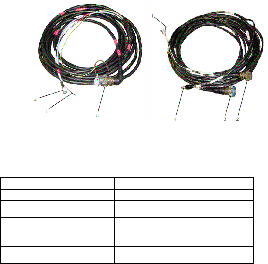
1.5.3 ELM-2127 Cable Physical Description
The ELM-2127 cable (Figure 1-7) connects the ELM-2127 sensor to power source and tactical
center.
NOTE
The ELM-2127 cable has two configurations:
1018E051-001 (for 1018E170-001) - includes a
single connector for power and communication.
1018E247-001 (for 1018E220-001) - includes two
connectors, J1 - power and J2 - communication.
Figure 1-7. ELM-2127 Cable
Table 1-2 details ELM-2127 cables elements.
Table 1-2. ELM-2127 Sensor Cables
No. Name Type Function
1 Power Wirers Connecting wires for 24 VDC power source
2 P1
(1018E247-001 only)
Circular
Connector
Provides ELM-2127 sensor power supply.
3 P2
(1018E247-001 only)
Circular
Connector
Provides ELM-2127 sensor communication.
4 Ethernet RJ45 Ethernet connector to tactical center.
5 P1
(1018E051-001 only)
Circular
Connector
Provides ELM-2127 sensor power supply and
communication.
UNCLASSIFIED
13083 13 OF 24
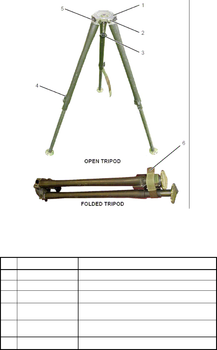
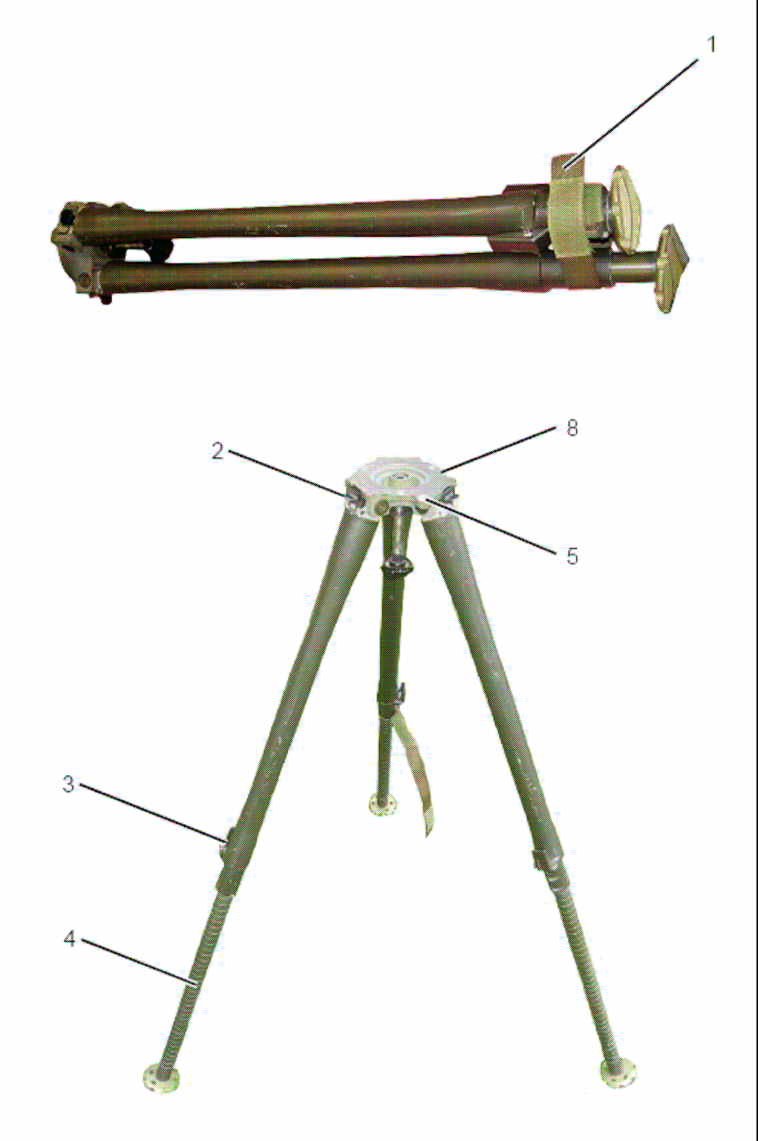
1.5.4 ELM-2127 Tripod Physical Description
The ELM-2127 tripod (Figure 1-8) is used to mount the ELM-2127 sensor. The tripod is collapsible for
transportation.
Figure 1-8. ELM-2127 Tripod
Table 1-3 details ELM-2127 tripod elements.
Table 1-3. ELM-2127 Tripod Elements
No. Name Function
1 Mounting Surface Used to mount ELM-2127 sensor
2 Level Used to level the tripod.
3 Securing Screw Provides ELM-2127 sensor power supply.
4 Latches (3) Three latches used to locks tripod legs, in open or
collapsed position.
5 Top latches Three latches use to maintain tripod legs in open
position.
6 Securing strip Use to secure the tripod when in collapsed position.

UNCLASSIFIED
13083 14 OF 24
1.6 ELM-2127 MAIN CHARACTERISTICS
Table 1-4. ELM-2127 Technical Characteristics
Parameter Characteristics
Frequency band “X” 10.4 ±0.1 GHz
Transmitted peak power 700 mW maximum
Transmitted average power 70 mW maximum
Azimuth coverage 120º
Azimuth beam width 15º
Azimuth side lobes • 1
st
: -20 dB
• Average: -35 dB
Azimuth accuracy 1.5º
Elevation beam width 10º
Antenna gain 23.5 ±0.5 dB
Digital signal processing • Digital matched filter
• LFM pulse compression
• FFT (Doppler), IFFT (range), CFAR,
Monopulse Azimuth
• TWS
External Communication Ethernet 10/100 BaseT
Input power 24 VDC nominal
Power consumption 60W
MTBF 5,000 h calculated
Table 1-5. ELM-2127 Physical Characteristics
Parameter Characteristics
Weight ~16KG
Dimensions L=50, D=32, H=30 cm
Operation ambient temperature -30 to +45 ºC
Storage temperature -40 to +85 ºC
Rain The equipment is sealed and designed to operate in
rainy conditions.
Humidity 88% relative humidity.

UNCLASSIFIED
13083 15 OF 24
CHAPTER 2
DEPLOYMENT
2.1 SCOPE
This chapter details ELM-2127 system preparation for use, including deployment and installation.
2.2 SENSOR LOCATION SELECTION
The ELM-2127 sensor is located at a point from which there is a free line of sight from the radar to
the entire transmission area around the radar. Verify ELM-2127 sensor is positioned as far as
possible from fixed or mobile radio emitting equipment such as communication sets of any type or
other radars.
The ELM-2127 sensor is should not be deployed near high power electrical cables. Verify that no
high power electrical cables are located within 30 m around the sensor or 10 m above the sensor.
Operator post can be located at a remote location or close to the ELM-2127 sensor.
NOTE: This equipment generates, uses, and can radiate radio frequency energy
and, if not installed and used in accordance with the instruction manual, may
cause harmful interference to radio communications. Operation of this
equipment in a residential area is likely to cause harmful interference in which
case the user will be required to correct the interference at his own expense.
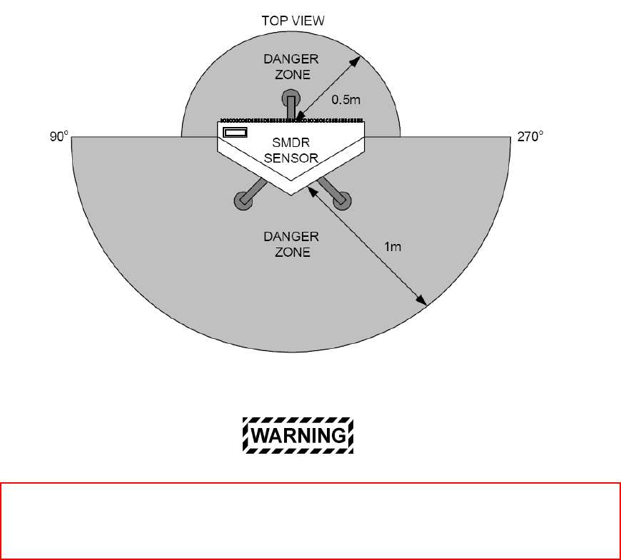
ELM-2127 sensor emits electromagnetic radiation. Verify no personnel are located
within the danger area of 1m from the front sector of the sensor and 0.5m from the rea
r
sector of the sensor (Figure 2-1). To comply with FCC RF exposure requirements, this
radar must be installed to provide a separation distance of at least 2 meters from all
persons. See FCC ID and Warning Label on the top access cover of the radar.
UNCLASSIFIED
13083 16 OF 24
Figure 2-1. ELM-2127 Sensor RF Radiation Danger Area
Changes or modifications to this equipment not expressly approved by ELTA Systems, Ltd.
could void the user’s authority to operate the equipment.
UNCLASSIFIED
13083 17 OF 24
2.3 ELM-2127 DEPLOYMENT
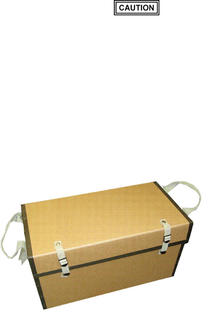
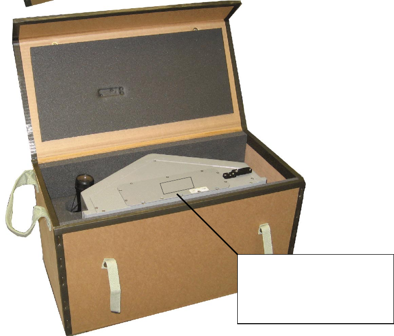
2.3.1 Unpacking ELM-2127 Sensor
To unpack ELM-2127 sensor, proceed as follows:
ELM-2127 sensor radome is sensitive to mechanical
damage. While moving the ELM-2127 sensor, verify
radome does not come in contact with sharp or abrasive
objects. Do not rest the ELM-2127 sensor with the
radome facing down, on the radome corners or edges.
Failure to comply may cause damage to ELM-2127
sensor radome.
1) Verify ELM-2127 storage box [1] is intact and without any visible damage.
2) Release ELM-2127 storage box locking strips [2] and open the box.
3) Using ELM-2127 sensor carrying handles, carefully remove ELM-2127 sensor (3) from the
storage box.
4) Visually inspect ELM-2127 sensor and verify its exterior is intact and clear of dust or dirt. If
required, clean it using soft dry cloth.
UNCLASSIFIED
13083 18 OF 24
Figure 2-2. ELM-2127 Sensor Unpacking
ELM-2127 FCC ID: XWR2127
Manufacturer: ELTA SYSTEMS Ltd.
To comply with FCC RF exposure
requirements, the radar must be installed
to provide a separation distance of at
least 2 meters from all persons
E
E
E
EL
L
L
LM
M
M
M-
-
-
-2
2
2
21
1
1
12
2
2
27
7
7
7
F
F
F
FC
C
C
CC
C
C
C
I
II
ID
D
D
D:
::
:
X
X
X
XW
W
W
WR
R
R
R2
2
2
21
1
1
12
2
2
27
7
7
7
M
M
M
Ma
a
a
an
n
n
nu
u
u
uf
ff
fa
a
a
ac
c
c
ct
tt
tu
u
u
ur
r
r
re
e
e
er
r
r
r:
::
:
E
E
E
EL
L
L
LT
T
T
TA
A
A
A
S
S
S
SY
Y
Y
YS
S
S
ST
T
T
TE
E
E
EM
M
M
MS
S
S
S
L
L
L
Lt
tt
td
d
d
d.
..
.
T
T
T
To
o
o
o
c
c
c
co
o
o
om
m
m
mp
p
p
pl
ll
ly
y
y
y
w
w
w
wi
ii
it
tt
th
h
h
h
F
F
F
FC
C
C
CC
C
C
C
R
R
R
RF
F
F
F
e
e
e
ex
x
x
xp
p
p
po
o
o
os
s
s
su
u
u
ur
r
r
re
e
e
e
r
r
r
re
e
e
eq
q
q
qu
u
u
ui
ii
ir
r
r
re
e
e
em
m
m
me
e
e
en
n
n
nt
tt
ts
s
s
s,
,,
,
t
tt
th
h
h
he
e
e
e
r
r
r
ra
a
a
ad
d
d
da
a
a
ar
r
r
r
m
m
m
mu
u
u
us
s
s
st
tt
t
b
b
b
be
e
e
e
i
ii
in
n
n
ns
s
s
st
tt
ta
a
a
al
ll
ll
ll
le
e
e
ed
d
d
d
t
tt
to
o
o
o
p
p
p
pr
r
r
ro
o
o
ov
v
v
vi
ii
id
d
d
de
e
e
e
a
a
a
a
s
s
s
se
e
e
ep
p
p
pa
a
a
ar
r
r
ra
a
a
at
tt
ti
ii
io
o
o
on
n
n
n
d
d
d
di
ii
is
s
s
st
tt
ta
a
a
an
n
n
nc
c
c
ce
e
e
e
o
o
o
of
ff
f
a
a
a
at
tt
t
l
ll
le
e
e
ea
a
a
as
s
s
st
tt
t
2
2
2
2
m
m
m
me
e
e
et
tt
te
e
e
er
r
r
rs
s
s
s
f
ff
fr
r
r
ro
o
o
om
m
m
m
a
a
a
al
ll
ll
ll
l
p
p
p
pe
e
e
er
r
r
rs
s
s
so
o
o
on
n
n
ns
s
s
s

UNCLASSIFIED
13083 19 OF 24
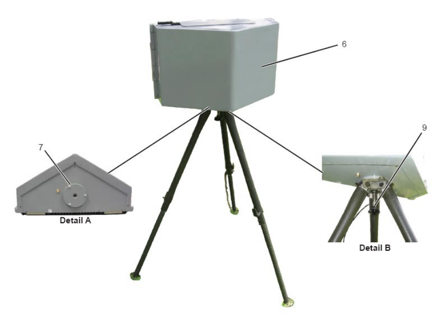
2.3.2 ELM-2127 Installation on Tripod
To install ELM-2127 sensor on the tripod, proceed as follows (Figure 2-3):
1) Open tripod securing strip [1] and spread tripod legs. Verify leg top latches [2] are locked.
2) Release tripod legs latches [3] and adjust tripod legs [4] height.
3) Position the tripod and level it by adjusting legs height. Verify tripod level bubble [5] is positioned
at the center of the circle in the leveling window.
Verify three leg latches are properly locked before
installing ELM-2127 sensor. Failure to comply may cause
damage to ELM-2127 sensor.
4) Mount ELM-2127 sensor [6] on the tripod so that three protrusions [7] on the sensor mounting
surface fit into three depressions [8] on the tripod.
5) Using securing screw [9], secure ELM-2127 sensor to tripod.
UNCLASSIFIED
13083 20 OF 24
Figure 2-3. ELM-2127 Sensor Installation on Tripod (1 of 2)
UNCLASSIFIED
13083 21 OF 24
Figure 2-3. ELM-2127 Sensor Installation on Tripod (2 of 2)

UNCLASSIFIED
13083 22 OF 24
2.3.3 ELM-2127 Installation on Pole
To install ELM-2127 sensor on the pole, proceed as follows:
1) Verify pole mounting jig is installed on the pole, and adjust its height and azimuth.
Pole mounting jigs should be design to support ELM-
2127 sensor weight and to prevent vibration in azimuth
and elevation.
2) Mount ELM-2127 sensor on the pole mounting jig, and secure it using four screws.
UNCLASSIFIED
13083 23 OF 24
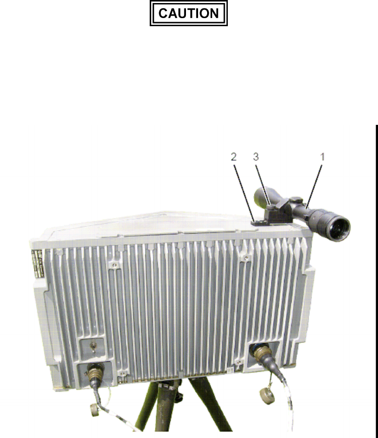
2.3.4 ELM-2127 Sensor Northing
To align ELM-2127 sensor to required azimuth, proceed as follows (Figure 2-4):
1) Install telescope [1] on ELM-2127 sensor telescope base [2] and secure it using securing screw
[3].
2) Remove lens protective covers.
3) Aim the telescope an object in the horizon, whose azimuth is known.
Use the carrying handles to move the ELM-2127 sensor
or to adjust its direction. Do not apply any force on the
telescope or radome. Failure to comply may cause
damage to ELM-2127 sensor or telescope.
4) Record the ELM-2127 sensor azimuth for further use.
Figure 2-4. Aligning ELM-2127 Sensor Azimuth
UNCLASSIFIED
13083 24 OF 24
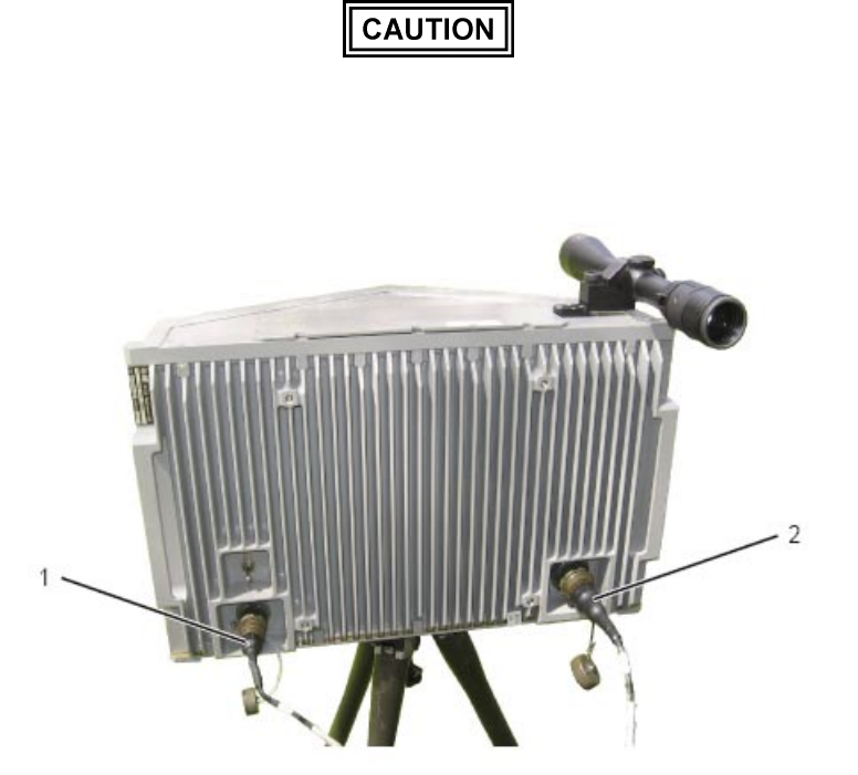
2.3.5 ELM-2127 Connecting to Tactical Center and Power
To connect ELM-2127 sensor to the tactical center and power, proceed as follows (Figure 2-5):
NOTE
1018E220-001 - includes two connectors:
J1 - power and J2 - communication (using
1018E247-001 cable).
The following description refers to 1018E220-001
configurations.
1) Connect cable power connector P1 to ELM-2127 sensor J1 [1].
2) Connect cable communication connector P2 to ELM-2127 sensor J2 [2].
3) Connect cable Ethernet connector (RJ45) to tactical center Ethernet connector.
4) Connect cable power wires to 24 VDC power source.
Verify 24 VDC power source output is stable without
interruption or power drops. Failure to comply may cause
damage to the ELM-2127 sensor.
Figure 2-5. Connecting ELM-2127 Sensor to Tactical Center and Power