Embeded Designs BS KIC Base Station User Manual KIC 2000
Embeded Designs KIC Base Station KIC 2000
UserManual.wiki
>
Embeded Designs
>
BS User Manual
>
Manual Part 1
Contents
1.
Manual Part 1
2.
Manual Part 2
Manual Part 1
Navigation menu
Upload a User Manual
Namespaces
Wiki Guide
HTML
PDF
Info
Views
User Manual
Discussion / Help
Navigation


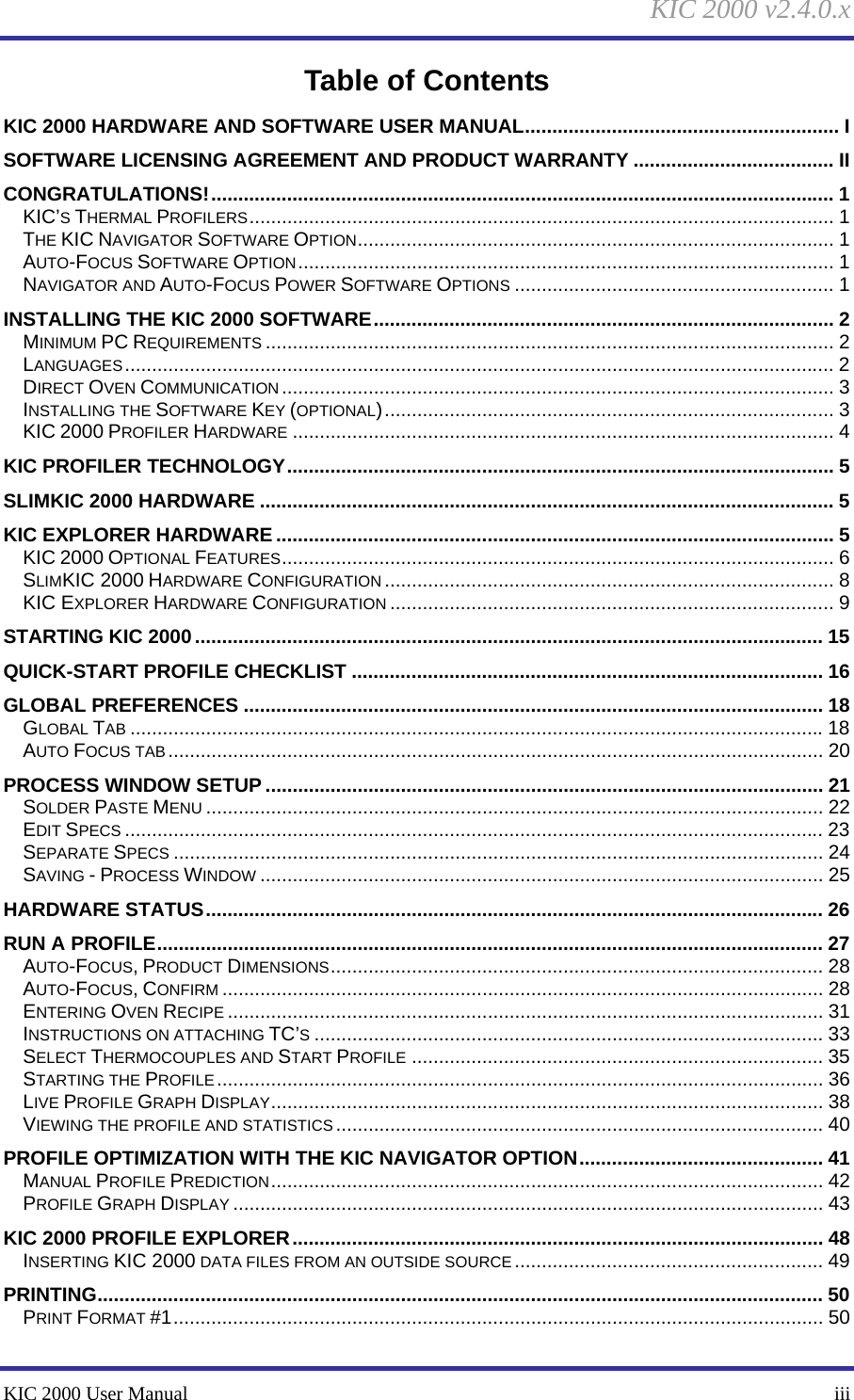

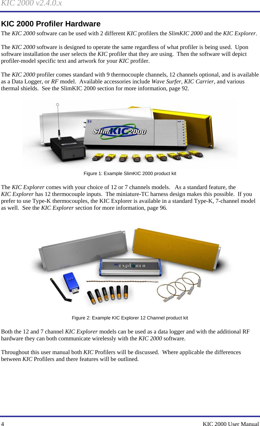


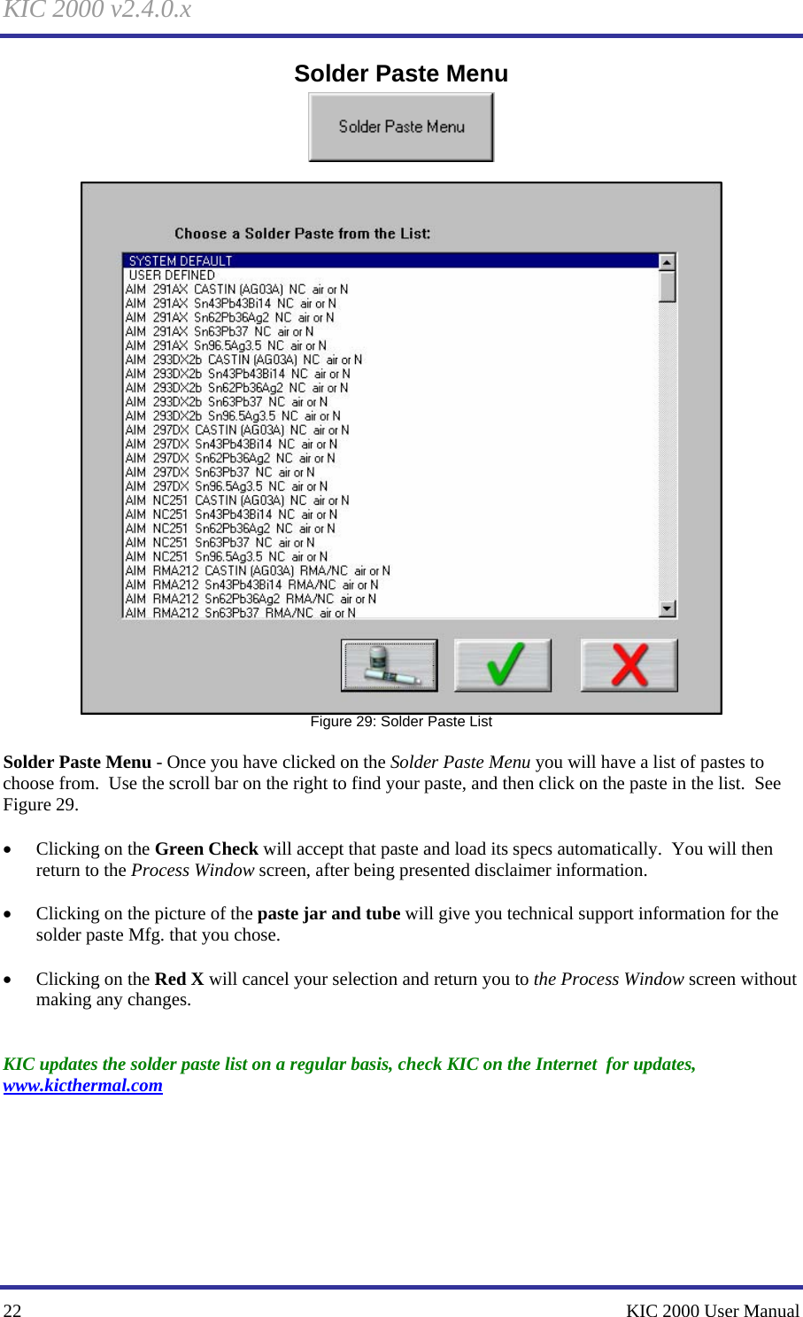
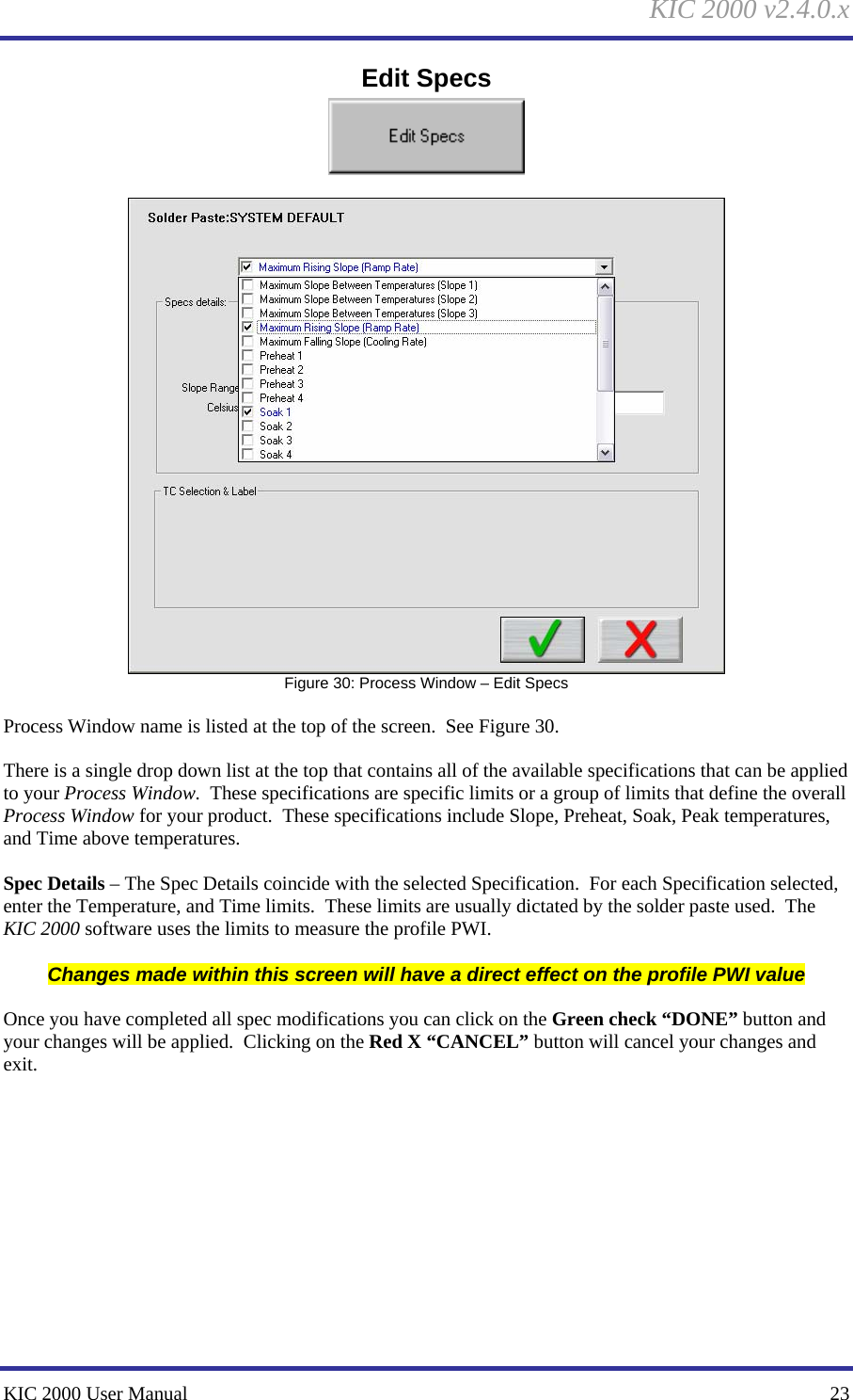
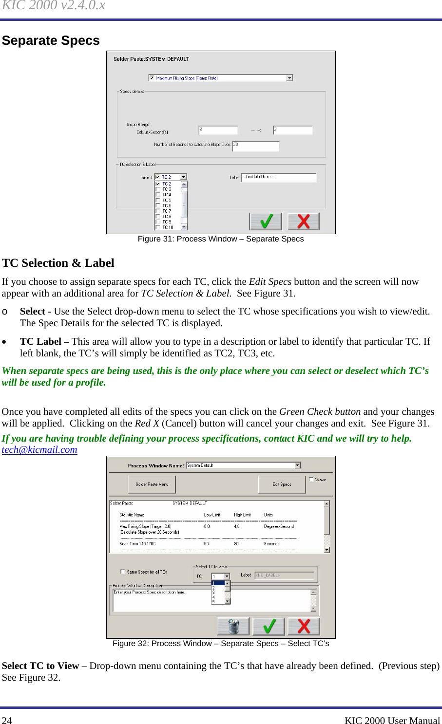
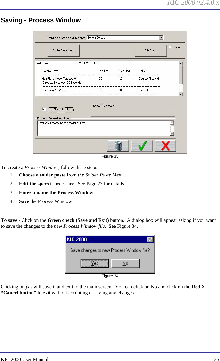
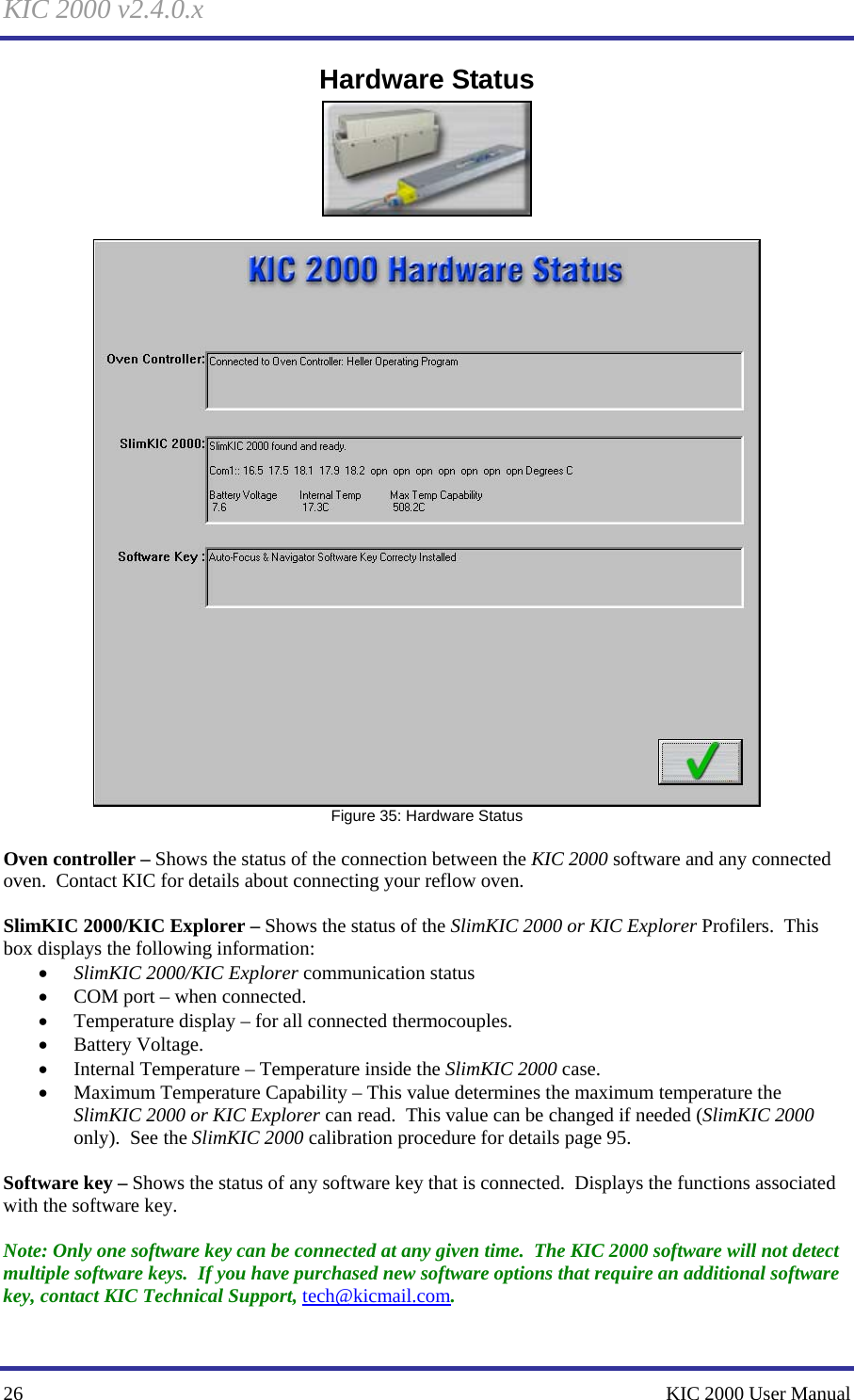
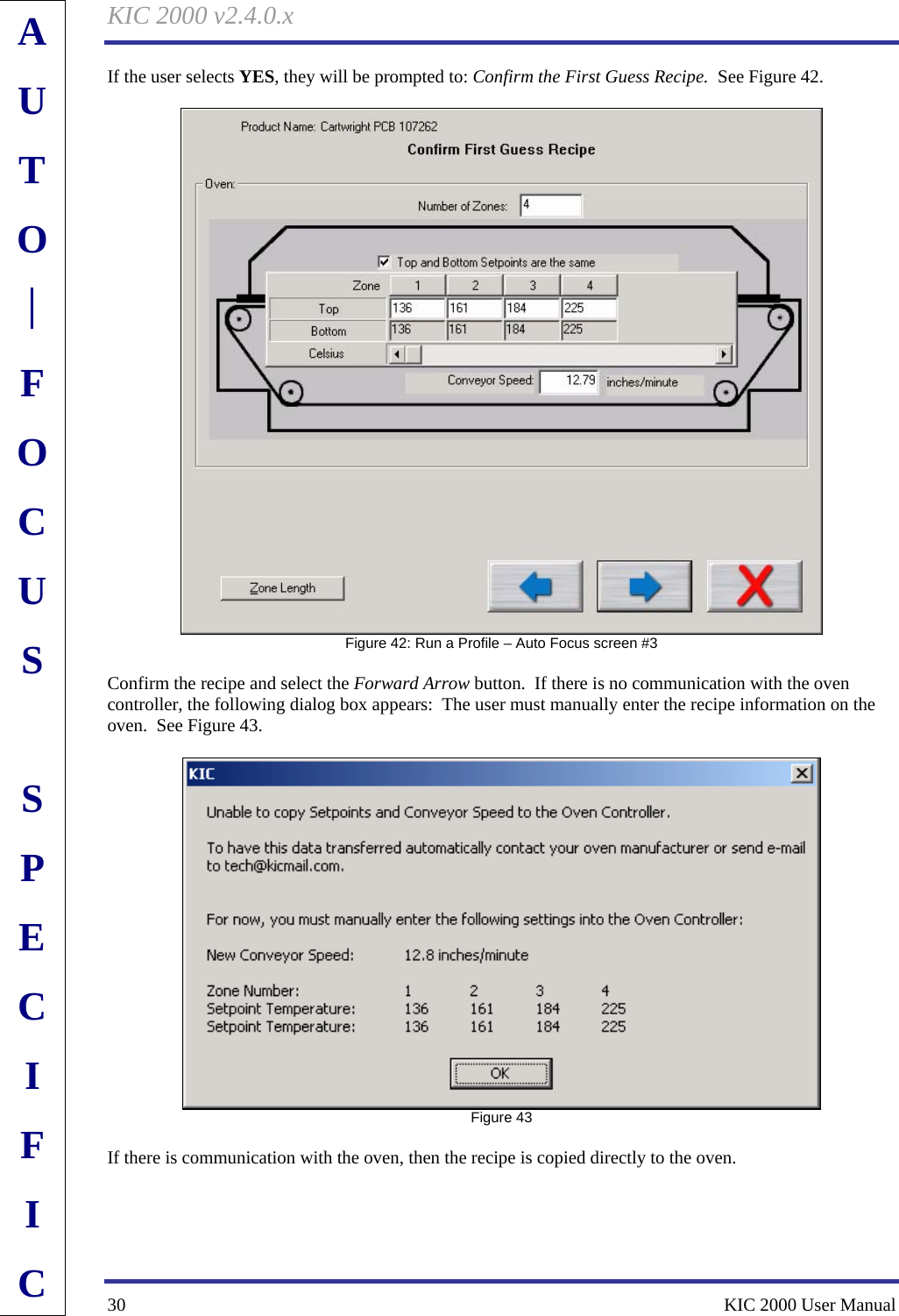
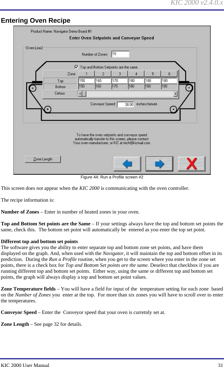

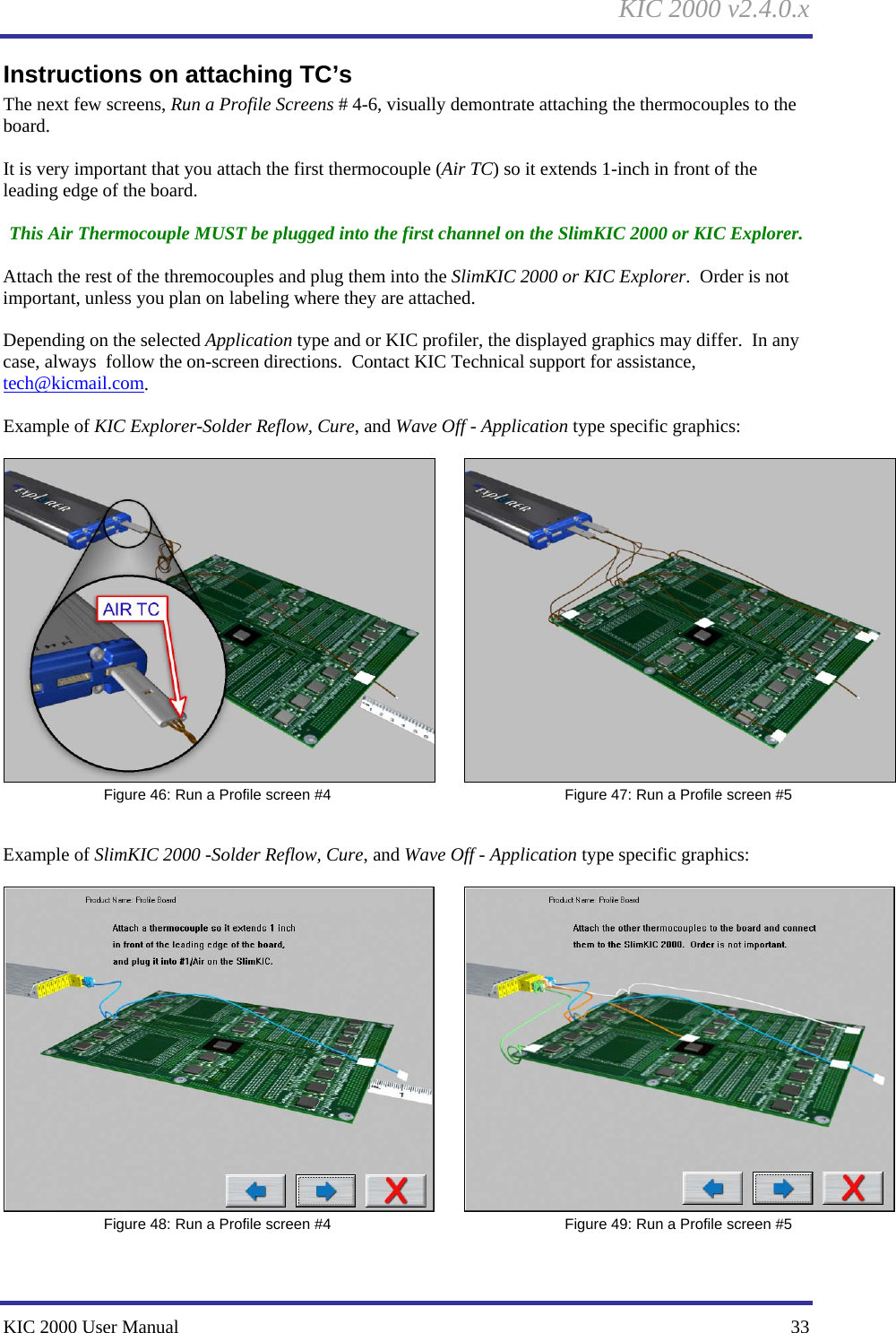
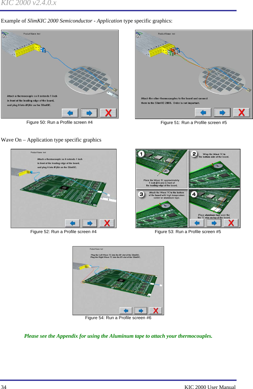
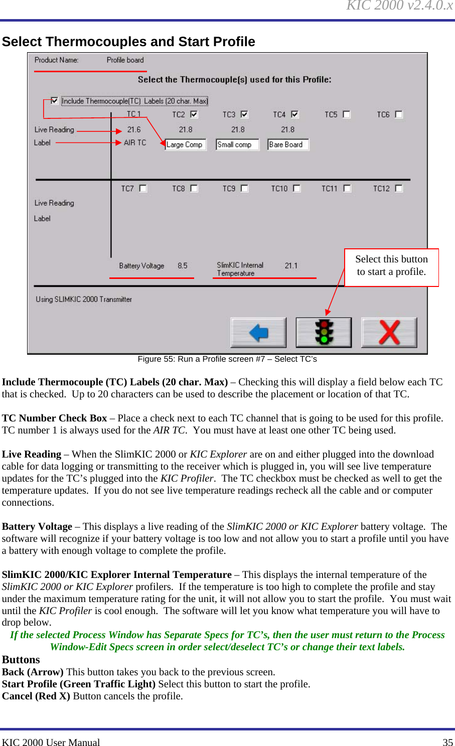
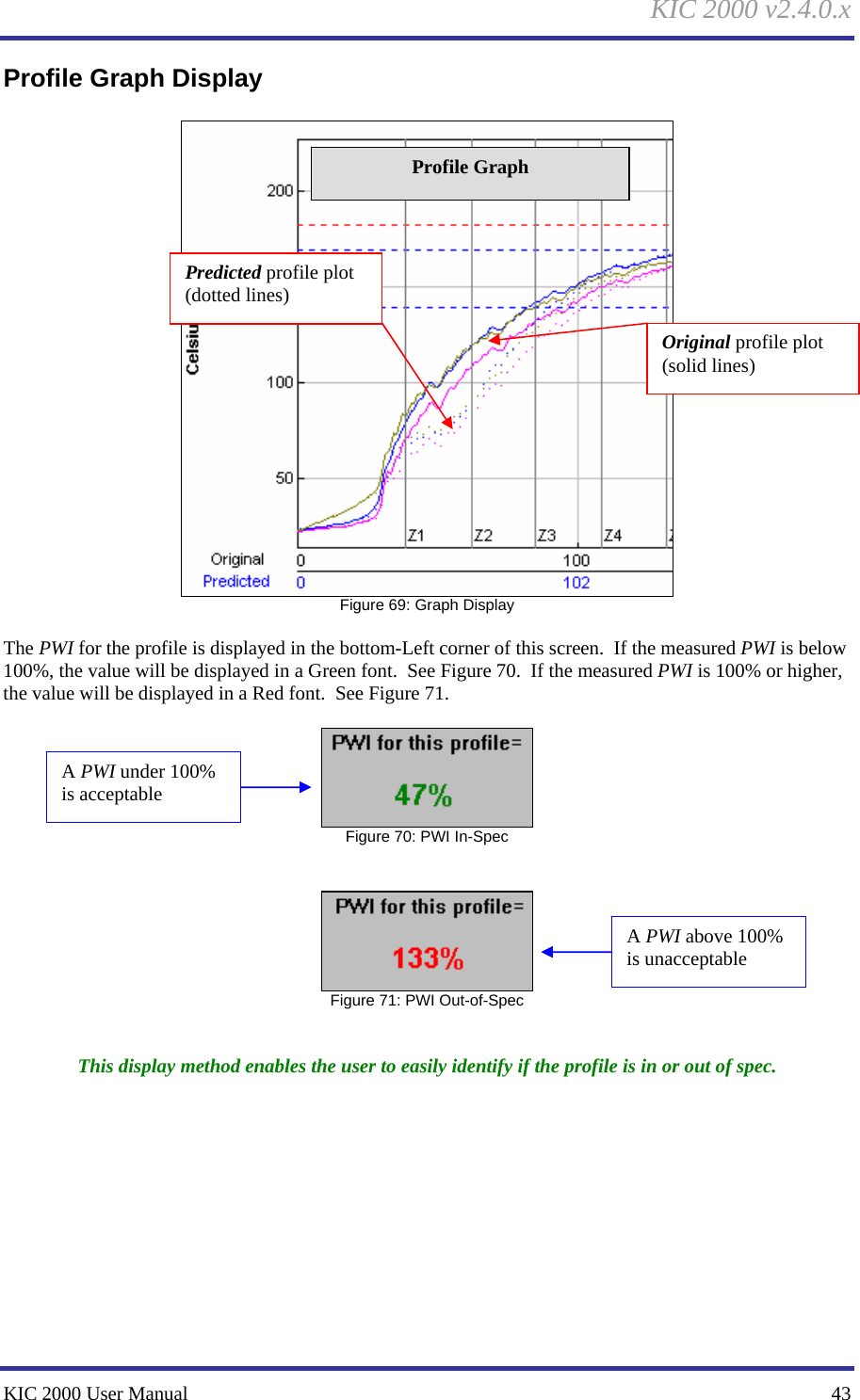
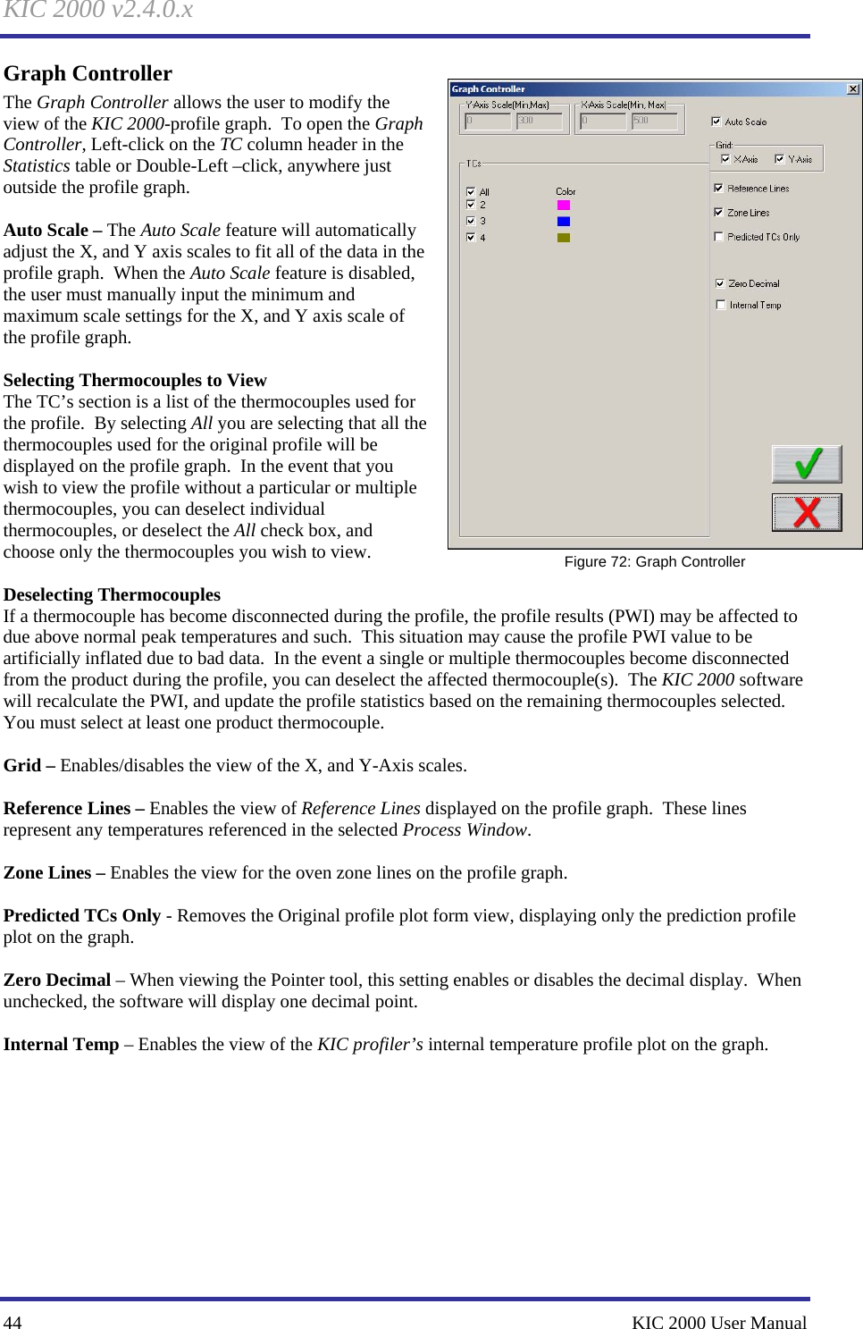
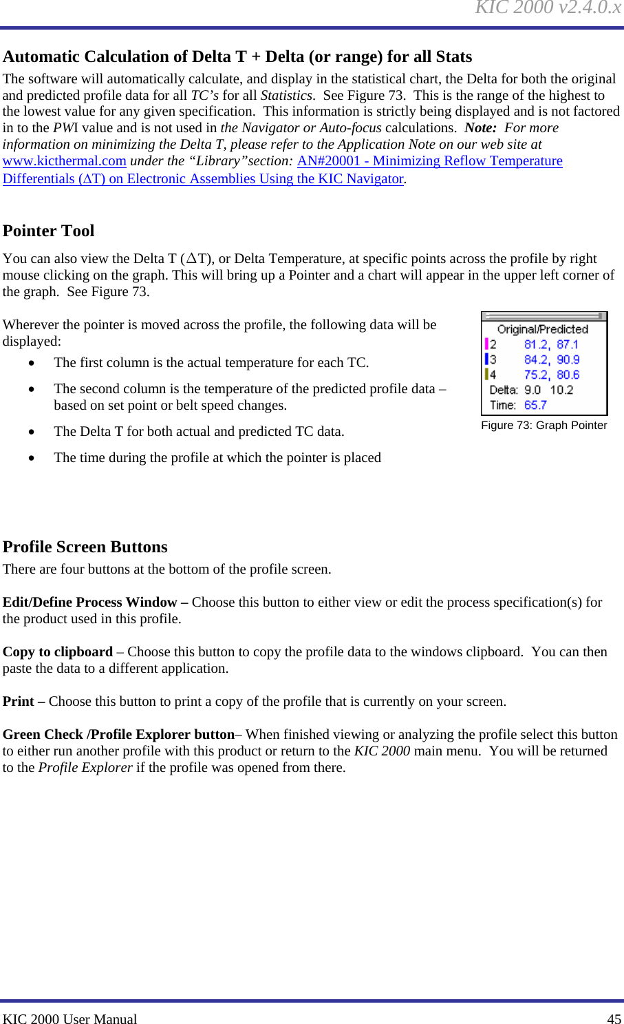
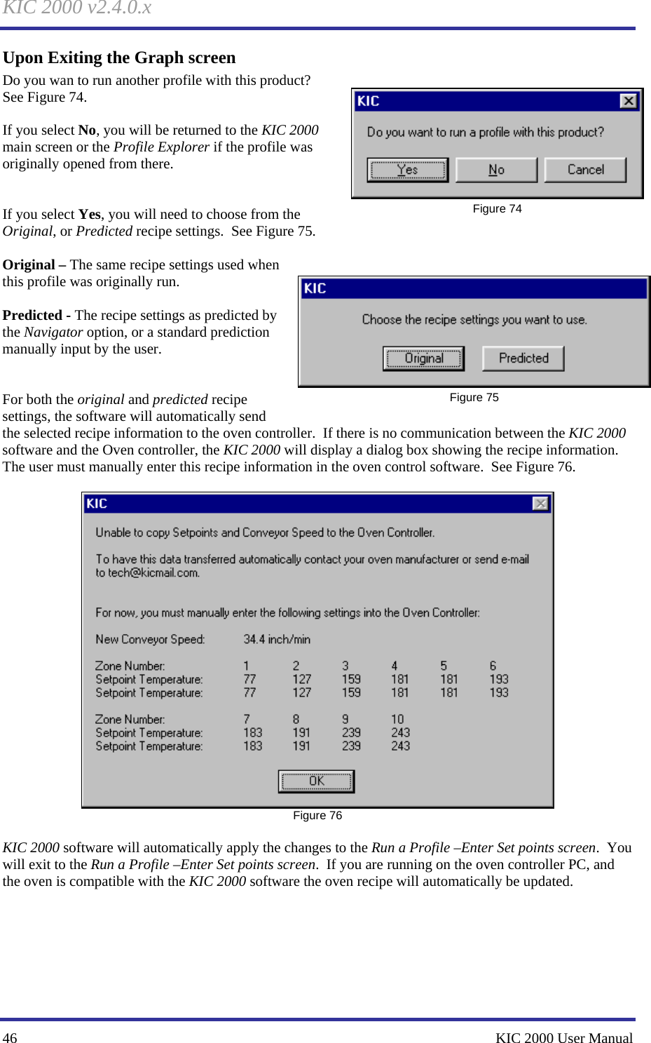
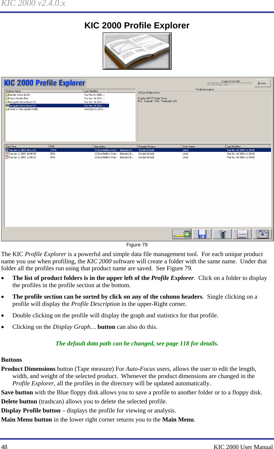

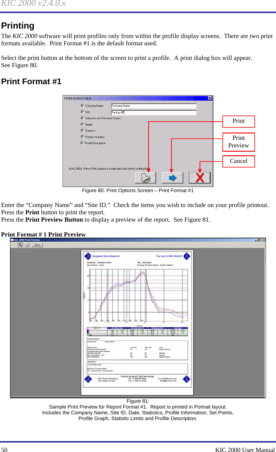
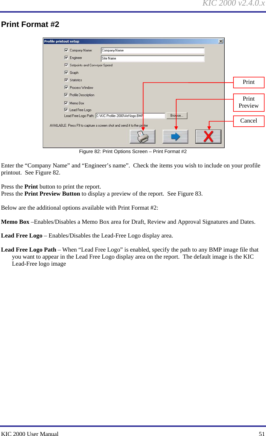
![KIC 2000 v2.4.0.x 52 KIC 2000 User Manual Print For mat # 2 Print Preview Figure 83: Sample Print Preview for Report Format #2. Report is printed in Landscape layout. Includes the Company Name, Engineer, Date, Statistics, Process Window, Set Points, Profile Graph, Profile Description, Lead-Free Logo Area and Memo Box Area Optionally, you can print the contents of any screen in the KIC 2000 software by pressing F9 on your keyboard. The F9 function will not work while viewing the Profile Printout Setup dialog box. Before printing make sure you defined a printer for use with Windows. Changing Print Formats The default Print Format is #1 (Portrait). Includes the Company Name, Site ID, Date, Statistics, Profile Information, Set Points, Profile Graph, Statistic Limits and Profile Description. You can change the default format by editing a KIC 2000 configuration file. To change Print formats follow these steps: 1. Close the KIC 2000 software if open. 2. Using Windows Explorer, find and open the file: C:\KIC Profiler 2000\Log\GControl.kiccfg 3. Find the command line that reads: [PRINT_FORMAT] AlternativePrintFormat=0 4. Change the command line to read: [PRINT_FORMAT] AlternativePrintFormat=1 5. Save and exit the file: C:\KIC Profiler 2000\Log\GControl.kiccfg 6. Restart the KIC 2000 software, the new print format will be active. Confirm by printing a profile.](https://usermanual.wiki/Embeded-Designs/BS.Manual-Part-1/User-Guide-857735-Page-58.png)