Emerson Process Management El O Matic E And P Series E25 E950 Users Manual
P2500 to the manual 22aa08c1-11cf-4a36-b294-aa60443dd2f9
2015-02-06
: Emerson-Process-Management Emerson-Process-Management-El-O-Matic-E-And-P-Series-E25-E950-Users-Manual-540079 emerson-process-management-el-o-matic-e-and-p-series-e25-e950-users-manual-540079 emerson-process-management pdf
Open the PDF directly: View PDF ![]() .
.
Page Count: 59
El-O-Matic E and P Series
Technical data pneumatic Rack and Pinion actuators
Product Data sheets
DOC.DSE.PN.US Rev. *
0D\ 2011
www.El-O-matic.com
Data sheet
Copyright © Emerson Process Management. The information in this document is subject to change without notice.
Updated data sheets can be obtained from our website www.El-O-Matic.com or from your nearest Valve Automation Center USA: +1 813 319 0266 Europe: +31 74 256 10 10 Asia-Pacific: +65 6501 4600
www.El-O-matic.com
Sheet No.:
Date: June 2010
A1.102 Rev. B
91.5°
A B
A B
AB
E-series
ED = Double acting ES = Spring return
91.5°
A B
A B
AB
11°
Adjustable
range*
91°
Open
* only standard on E-Serie actuators
-0.5° Closed
91.5°
A B
A B
AB
P-series
PD = Double acting PS = Spring return
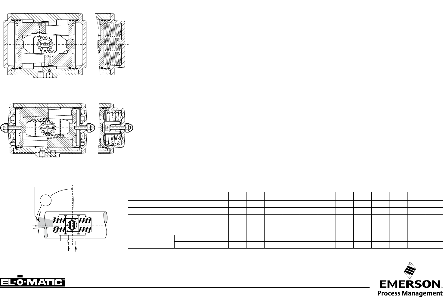
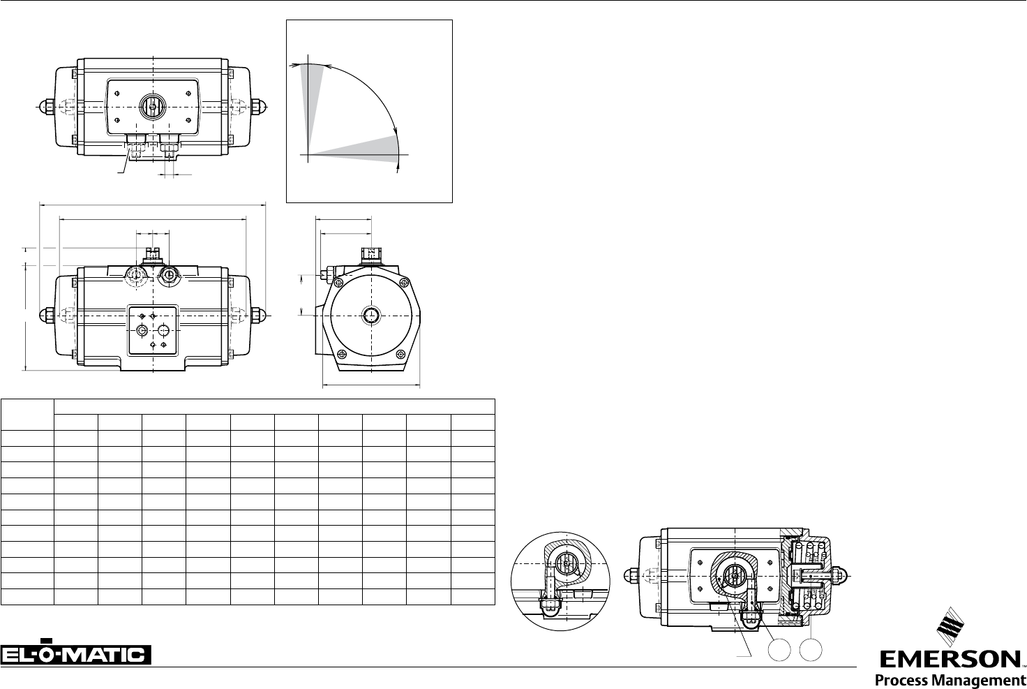
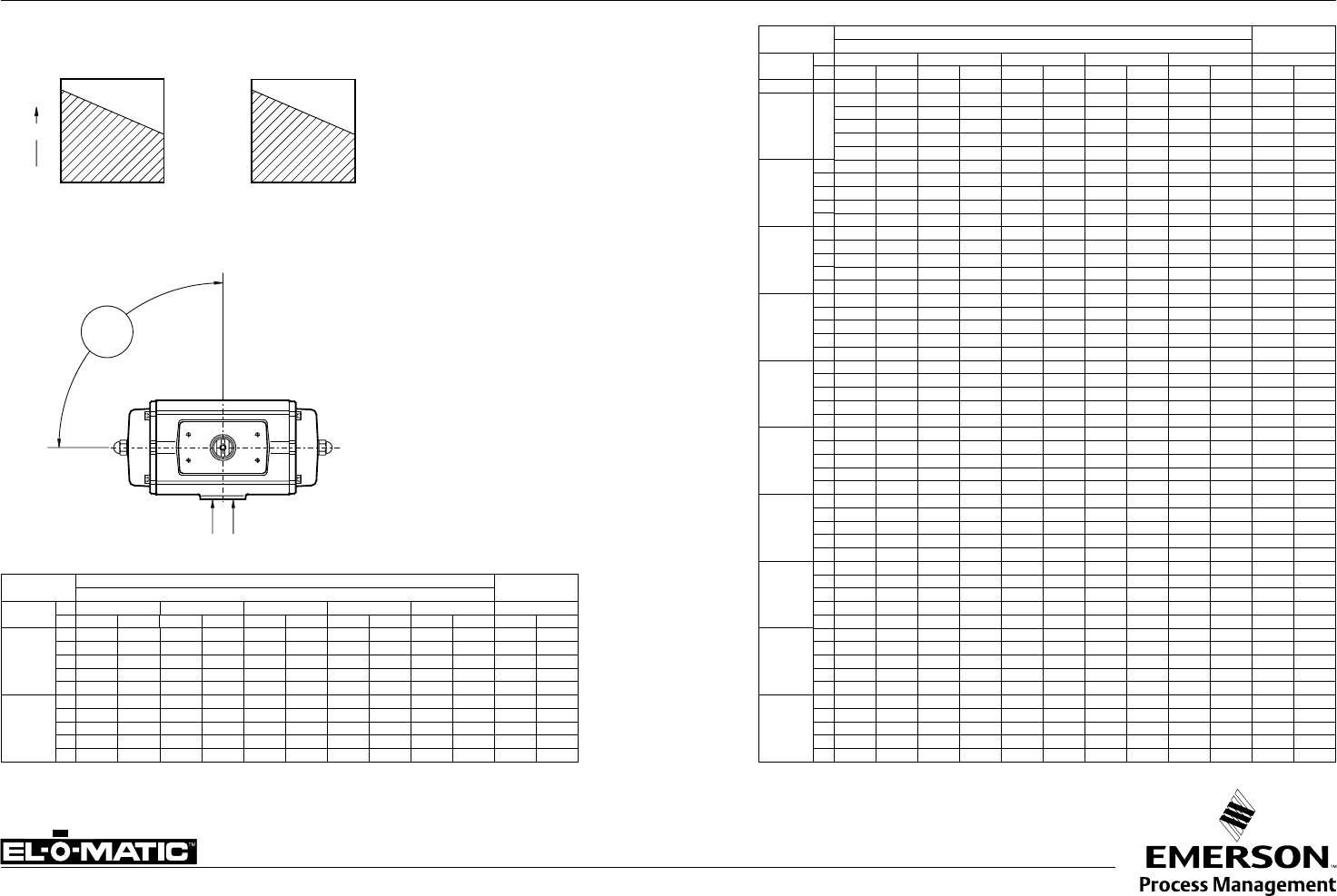
TECHNICAL DETAILS, STANDARD ACTUATOR E/P
ACTUATOR TYPE E12 E25 E40 E65 E100 E150 E200 E350 E600 E950 E1600 P2500 P4000
Bore inch 1.8 2.2 2.8 3.1 3.6 4.1 4.3 5.7 6.9 7.9 9.1 11.8 12.8
Stroke inch 0.5 0.6 0.7 0.9 1.0 1.2 1.5 1.5 1.7 2.0 2.5 2.2 3.2
Weight: Double acting lb. 1.3 2.9 4.0 5.3 6.8 10.5 12.8 23 43 58 94 125 191
Spring return lb. 1.5 3.7 5.3 7.9 10.1 15.2 20.1 37 61 85 145 194 291
Operating time sec. 0.4 0.5 0.7 1.1 1.2 1.8 2.3 3.6 4.5 5.4 6.9 7 12
Air consumption at
1 atm (cu./in.)
port A stroke 3.1 6.1 9.8 20 21 45 49 110 177 287 445 488 824
port B stroke 3.7 6.7 13 22 30 40 61 116 189 299 488 568 1,068
Specification
Pressure range : Double acting 20 to 120 psi
: Spring return 80 to 120 psi,, with max. spring set
40 to 120 psi, reduced spring
quantity
: 180° actuators 87 psi maximum
Torque : 1133 to 40,000 in.lb at 80psi supply
See torque datasheets 1.104.01 and 1.104.02
Operating media : Air, dry or lubricated and inert gasses
: For sub-zero applications take appropriate measures
Temperature : -4° to +176°F
Lubrication : Factory lubricated for the normal life of the actuator
Construction : Suitable for indoor and outdoor installation
Finish : Polyester non-TGIC based powder coating
(see data sheet A4.204.01)
Rotation : 91.5° (-0.5° CW to 91° CCW)
Double acting : Standard counter clockwise with port "A" pressurized
(code A, see data sheet A1.503 for other assembly
codes)
Spring return : Clockwise fail action
(code A, see data sheet A1.504 for other assembly
codes)
Limit stops : Standard on E-series. Adjustable range 91°/80°
: Optional on P-series. See datasheet A1.501.01
: For double stroke adjustment. See datasheet
A1.501.05
European Directives
PED : All actuators are suiteable for use
with Group 2 gasses according to
Pressure Equippement Directive
97/23/EC
: Optional : actuators suiteable for
use with Group 1 gasses
ATEX : All basic actuators are suiteable
for use in hazardous area's
classified II 2 GD, zones 1 or 2
(Gasses) and 21 or 22 (Dust)
Russian Approvals
El-O-Matic E and P series pneumatic actuators are
available with the GOST-R and Rostechnadzor (RTN)
approvals.
Note
1. Operating time is average with actuator under load
and solenoid valve fitted.
2. Air consumption is the actual free air volume at 1 atm.
3. Pressure is in barg.

Data sheet
Copyright © Emerson Process Management. The information in this document is subject to change without notice.
Updated data sheets can be obtained from our website www.El-O-Matic.com or from your nearest Valve Automation Center USA: +1 813 319 0266 Europe: +31 74 256 10 10 Asia-Pacific: +65 6501 4600
www.El-O-matic.com
Sheet No.:
Date: November 2010
A1.102.10 Rev. C EL-O-MATIC BASIC PNEUMATIC ACTUATOR CONFIGURATION E/P
Single or Double action
ES or PS = Single acting, ED or PD = Double acting
Actuator size
E-series
0012 = E12 0025 = E25 0040 = E40 0065 = E65 0100 = E100 0150 = E150
0200 = E200 0350 = E 350 0600 = E600 0950 = E950 1600 = E1600
P-series
2500 = P2500 4000 = P4000
Valve flange
Metric Metric UNC/NPT Finish
ISO 5211 DIN 3337 ISO 5211
M = D = U = Standard
N = E = V = CSR coating (2 + Aluminum pinion
O = F = W = CSR coating (2 + Stainless Steel pinion (3
Limit stops
0 = No limit stops 1 = L1 One way limit stops 2 = Double Stroke Adjustment
Standard on P-series Standard on E-Series Standard on DSA-Series
Assembly code
Code Action Rotation Mounting
A = Spring to close clock wise in line with pipeline
B = Spring to close clock wise across pipeline
C = Spring to open counter clock wise across pipeline
D = Spring to open counter clock wise in line with pipeline
Spring set E-serie Spring set P-serie
00 = Double acting actuator 00 = Double acting actuator
01 = Springset 1 04 = Springset 4 04 = Springset 4 10 = Springset 10
02 = Springset 2 05 = Springset 5 06 = Springset 6 12 = Springset 12
03 = Springset 3 06 = Springset 6 08 = Springset 8 14 = Springset 14
Future expansion
A = Standard
Default Insert
Size (in mm.) (1 E12 E25 E40 E65 E100 E150 E200 E 350 E600 E950 E1600 P2500 P4000
- ISO or UNC 00 11 14 14 19 19 22 27 27 36 46 00 00
- DIN 00 11 14 14 17 17 22 22 27 36 46 00 00
Visual Indication Code
D = Disk K = Knob N = No visual indication
Temperature range
0 = Standard TS: 80°C (176°F) -20°C ( -4°F)
1 = High temp TS: 120°C (248°F) -20°C ( -4°F)
2 = Low temp TS: 80°C (176°F) -40°C (-40°F)
ES 0040.M 1 A 05 A.14 N 1 (1 Actuators E12, P2500 and P4000 have no inserts. They have have a inner square the shaft
180° actuators are not covered by this configuration matrix.
(2 CSR Coating not possible in combination with Double Stroke Adjustment limit stops (DSA series).
(3 Stainless Steel Pinion not possible in combination with Double Stroke Adjustment limit stops (DSA series).
See following data sheets
for more information
A1.104.01 / A1.104.02
A1.103.106 / A1.103.073 /
A1.103.102 / A1.103.103
A1.101.30 / A1.101.33 /
A4.204.01
A1.501.01/
A1.501.05
A1.503/
A1.504
A1.104.02
A1.103.073
A1.103.106
A1.103.120
A1.101.70 / A1.101.71
Data sheet
Sheet No.:
Date: November 2009
Copyright © Emerson Process Management. The information in this document is subject to change without notice.
Updated data sheets can be obtained from our website www.El-O-Matic.com or from your nearest Valve Automation Center USA: +1 813 319 0266 Europe: +31 74 256 10 10 Asia-Pacific: +65 6501 4600
www.El-O-matic.com
TM
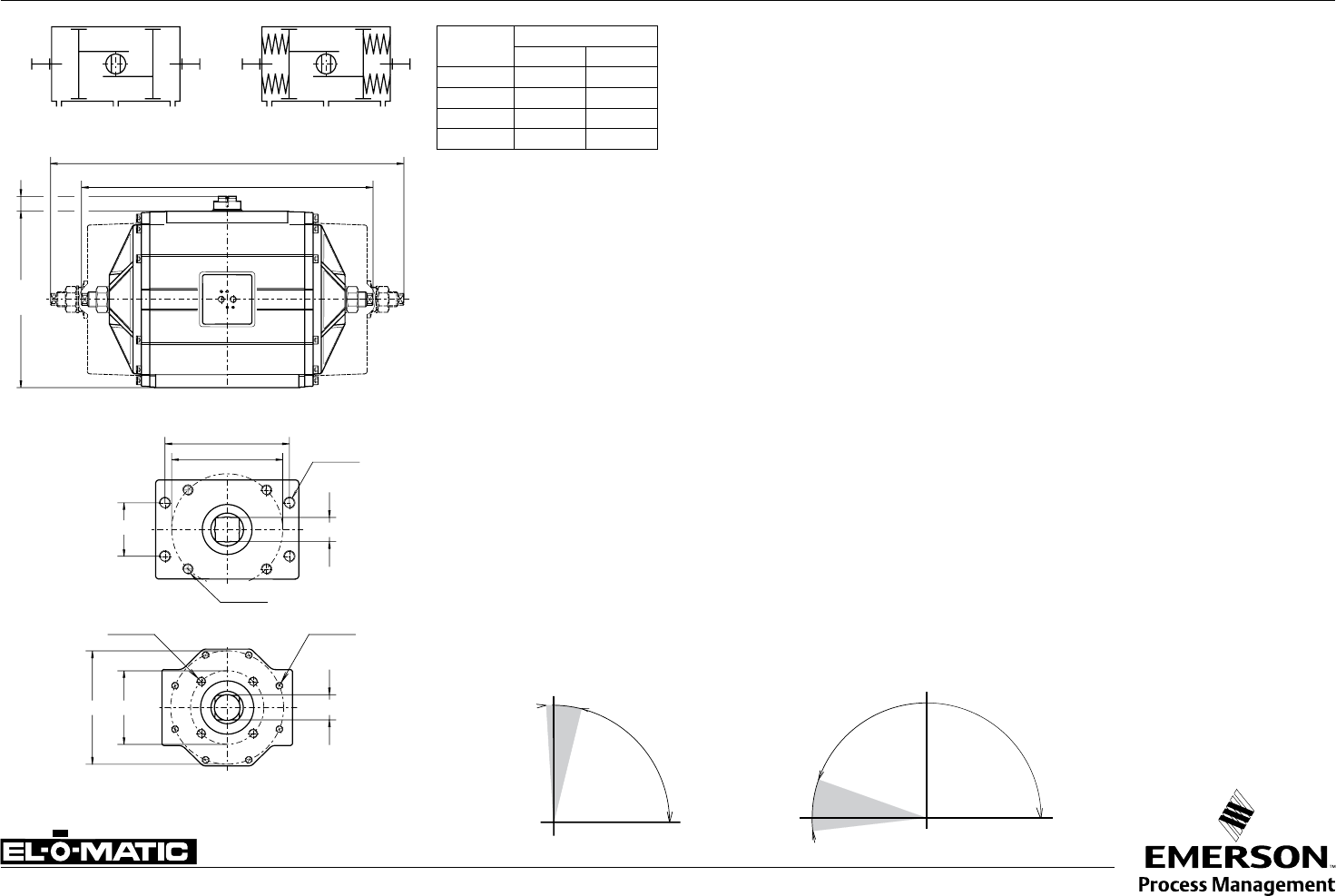
A1.501.01 Rev. A EL-O-MATIC ACTUATOR WITH ONE WAY LIMIT STOPS L1/LF
Description
Actuators with one way adjustable limit stops are used where the maximum opening (or closing)
position of the valve needs to be reduced. For instance to adjust the maximum capacity of a
remote operated valve.
Also actuators with 180° rotation are available with these stops.
Operation
Stop screws are fitted to both endcaps and the screw length is such that adjustment is possible
through the specified rotation of the actuator.
The modified endcap is machined for -0.5° to +93° rotation for all P-series models.
Identification
“L1” is added to the basic part number i.e. PD2500-L1
Specification:
Pressure : Up to 120 PSI
Media : Air, dry or lubricated or non-corrosive gas
Torque (90°) : Data sheet A1.104.01 - A1.104.04
(180°) : Data sheet P-serie A1.204.01 and A1.204.02
Other dimensions : Data sheet A 1.103.XXX (90°)
: Data sheet A 1.203.011 (180°)
Temperature : -4.0° to +176°F
Adjustable range : 80°-93°(90°) or 160°-186° (180°)
Adjustable position (see data sheet A1.503 or A1.504)
code position
A Valve open (spring to close)
B Valve open (spring to close)
C Valve closed (spring to open)
D Valve closed (spring to open)
Note:
1) Can be provided with extra long screws for full range adjustment
(identification: PD2500-LF)
2) This option in combination of a manual override gearbox is redundant
Dim.
in inch
ACTUATOR TYPE
P2500 P4000
A22.8 27.9
B31.3 45.4
C14.0 15
D1.2 1.2
B
A
C
D
3° 10°
Open Adjustable range
90° actuator
Adjustable range
180° actuator
-20°
+6°
Open Closed
Closed
Note: Do not adjust under pressure
B
A
C
D
DOUBLE ACTING SPRING RETURN
9.236
6.496
3.827
5/8"-11x.98
P2500
3/4"-10x1.14
1.811
5/8"-11x.98
P4000
2.16510.000
6.496
3/4"-
10x1.14
Data sheet
Sheet No.:
Date: November 2009
Copyright © Emerson Process Management. The information in this document is subject to change without notice.
Updated data sheets can be obtained from our website www.El-O-Matic.com or from your nearest Valve Automation Center USA: +1 813 319 0266 Europe: +31 74 256 10 10 Asia-Pacific: +65 6501 4600
www.El-O-matic.com
TM
A1.501.03 Rev. A LIMIT STOP PLATE DIMENSIONS LS 420
Dim.
in inches
ACTUATOR TYPE
P2500 P4000
E18.3 19.3
F5.3 5.3
G12.7 12.7
H5.1 5.6
O1.8 2.2
V165 165
WM20x30 M20x30
Description
These limit stop plates are used when precise control is required for both end of stroke positions.
It is possible to adjust 15° of both ends of the standard stroke.
Construction
The complete stop plate assembly may be added to the 90° P- series actuators.
The assembly is normally sandwiched between the actuator and mounting surface of the valve
or bracket. Bearing rings are used at both surfaces to provide a long life expectancy.
The unit is assembled with a drive adaptor which passes through the stop plate, into the square
actuator and provides the coupling between the two components.
This drive adaptor normally also accommodates the coupling of the valve stem.
Identification
"LS420" is added to the basic part number i.e. PD2500-LS420
Other dimensions
See data sheet A1.103.xxx
Option
Version for 180° or DIN-standard actuator
+1° -15°
+0.5°
-15°
E
Gmax.
F
WO
V
Hmax.
Drive shaft
Actuator base
Drive adaptor
Cover plate
Cam
Housing limit stop
+1° -15°
+0.5°
-15°
E
Gmax.
F
WO
V
Hmax.
Open
Closed
Adjustable range
90° actuators
Note: Cover plate only in combination with P2500
Data sheet
Sheet No.:
Date: November 2009
Copyright © Emerson Process Management. The information in this document is subject to change without notice.
Updated data sheets can be obtained from our website www.El-O-Matic.com or from your nearest Valve Automation Center USA: +1 813 319 0266 Europe: +31 74 256 10 10 Asia-Pacific: +65 6501 4600
www.El-O-matic.com
TM
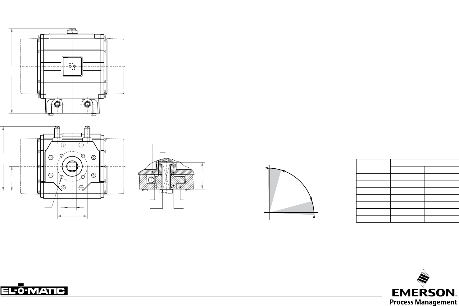
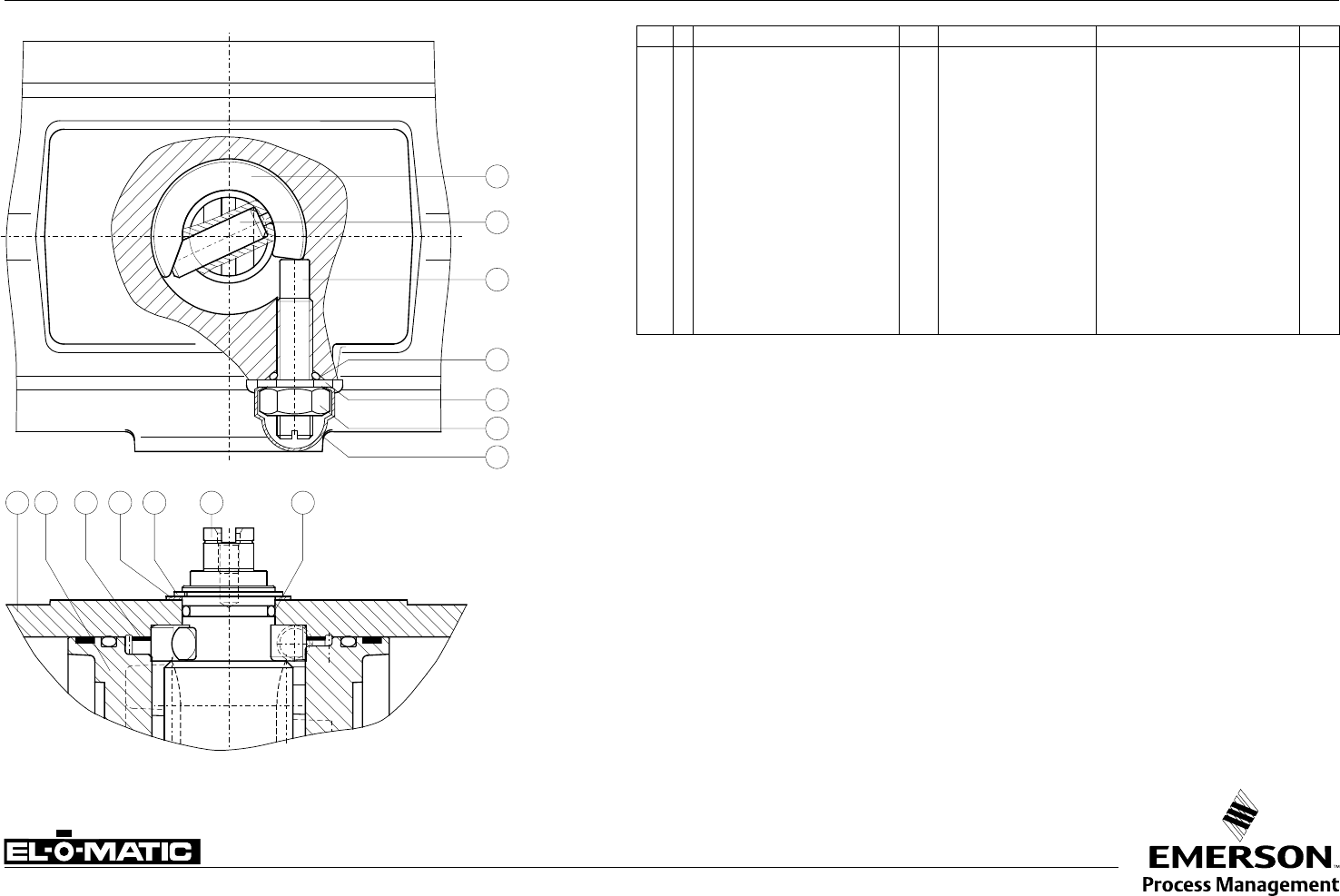
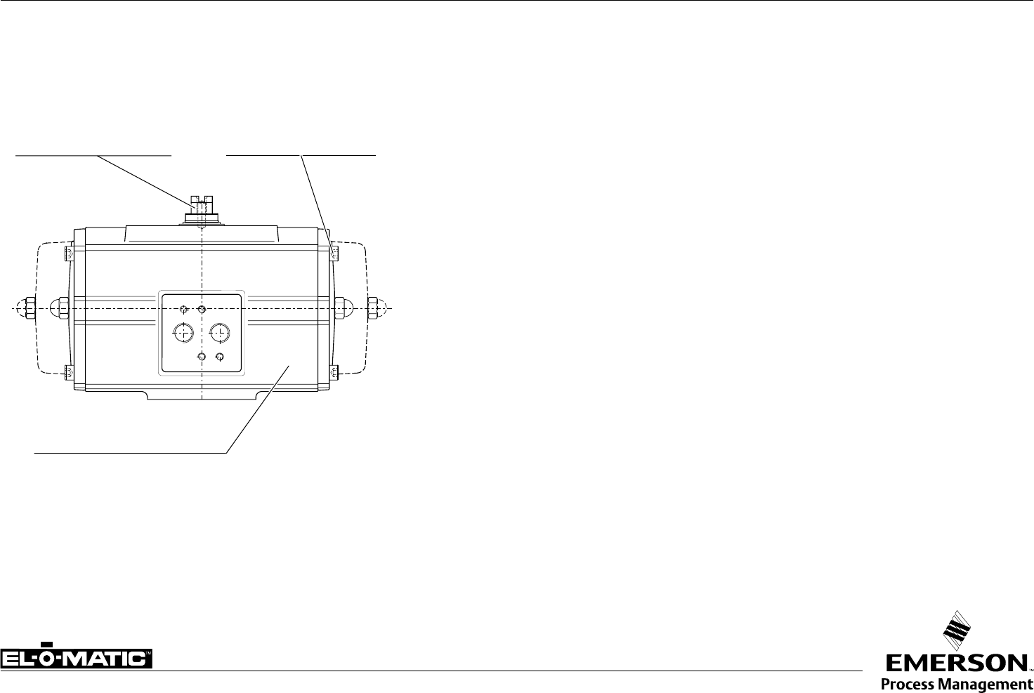
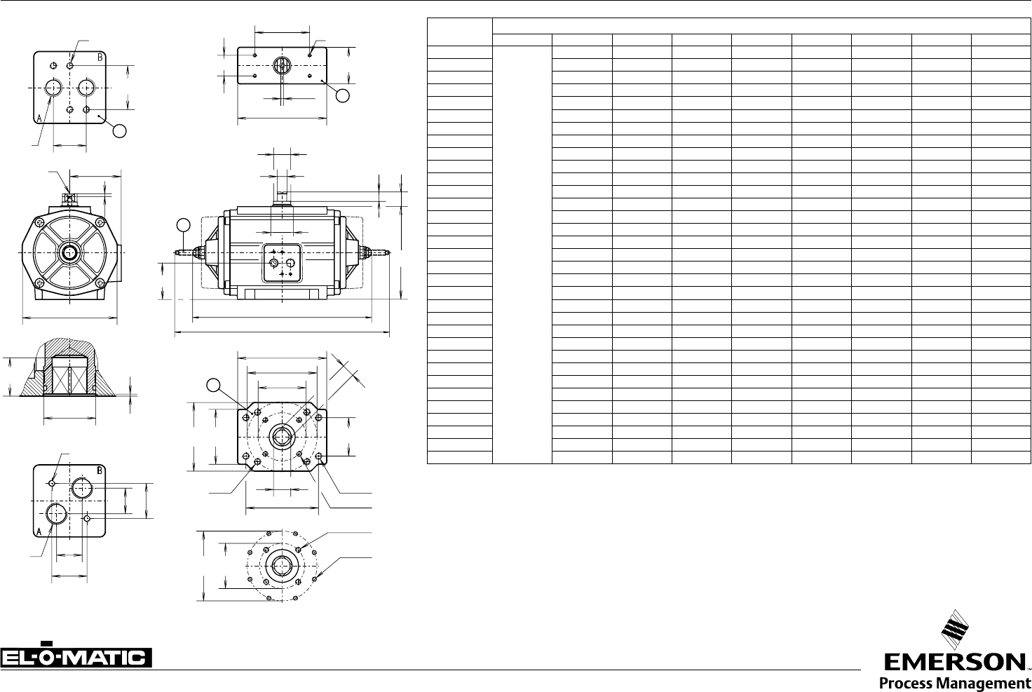
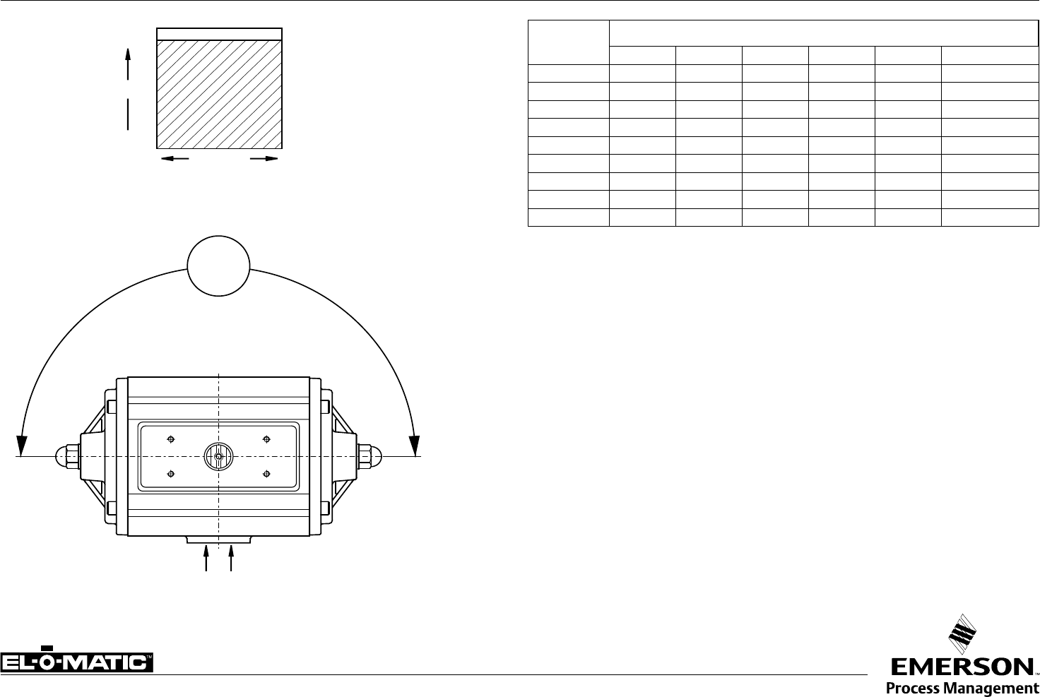
A1.501.05 Rev. A EL-O-MATIC ACTUATOR WITH DOUBLE STROKE ADJUSTMENT DSA
Dim.
in inch.
Actuator type
E25 E40 E65 E100 E150 E200 E350 E600 E950 E1600
A DA 6.26 7.09 7.83 8.70 10.00 11.14 12.01 15.35 17.32 20.47
B SR 6.77 8.03 9.80 10.51 12.20 14.17 15.24 18.90 20.94 25.24
C3.15 3.66 4.13 4.65 5.51 5.63 7.13 8.66 10.20 11.69
D0.79 0.79 0.79 0.79 0.79 0.79 0.79 1.18 1.18 1.18
H2.91 3.39 3.86 4.25 4.76 5.04 6.81 8.15 9.09 264.00
I1.81 2.01 2.26 2.48 2.76 2.87 3.71 4.45 4.96 5.59
J1 1.11 1.38 1.57 1.72 1.92 2.12 2.85 3.50 4.03 4.50
L0.45 0.61 0.61 0.73 0.97 0.97 0.97 1.63 1.63 1.87
Y1/4"-20 5/16"-18 5/16"-19 3/8"-16 3/8"-16 1/2"-13 1/2"-13 5/8"-11 5/8"-11 3/4"-10
X1.42 1.63 1.63 1.99 2.36 2.46 2.85 4.02 4.02 4.31
X max. 1.63 1.91 1.91 2.30 2.64 2.91 3.31 4.51 4.51 4.88
Y
A
B
C
H
I
X
J
1
LL
12
D
3° 10°
3°
15°
adjustable
range
Closed
stopscrew (1)
Open
stopscrew (2)
Factory option:
Fail to Open
Y
A
B
C
H
I
X
J
1
LL
12
D
3° 10°
3°
15°
Stroke adjustment cam
Factory option:
"Fail open"
Description
Actuators with double stroke adjustment are normally used for high performance butterfly valves
where a fine adjustment is required for the closed position. In this version adjustment is provided
at the end of the opening and closing stroke positions. DSA actuators may be double acting or
spring return, though are normally used as spring return (fail close) actuators.
Operation
The closed position is adjusted by means of the stop-screw (1) located in the actuator body and
for the open position by the stop-screws (2) in the actuator end caps.
Identification
See data sheet A1.102.10
Specification
Pressure : Up to 120 psi
Operating media : Air, dry or lubricated or non-corrosive gas
Torque (90°) : Data sheet A1.104.01 - A1.104.02
Rotation -
- Spring return : Clock-wise on air failure.
- Double acting : Counter clock-wise with port “A” pressurised.
Other dimensions : Data sheet A1.103.XXX
Temperature : -4° to +176° F
Adjustable range : Closed position (1), -3° - 15°
Open position (2), 80° - 93°
Note
1) Can be provided with extra long end-cap stop screws for full range adjustment of the “open”
position.
2) This DSA option is not required on actuators fitted with manual override gearboxes, as MO
gearboxes already incorporate this function.
Important
1) "Fail open" is factory option.
2) When assembled for “fail open” operation (code D; see data sheet A1.504), both stop-screws
(1) and (2) will adjust the closed position. There is no adjustment for the open position!
Data sheet
Copyright © Emerson Process Management. The information in this document is subject to change without notice.
Updated data sheets can be obtained from our website www.El-O-Matic.com or from your nearest Valve Automation Center USA: +1 813 319 0266 Europe: +31 74 256 10 10 Asia-Pacific: +65 6501 4600
www.El-O-matic.com
Sheet No.:
Date: May 2011
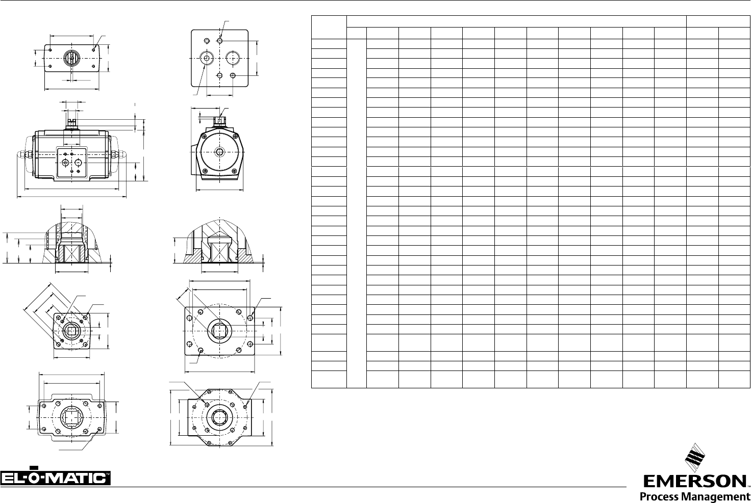
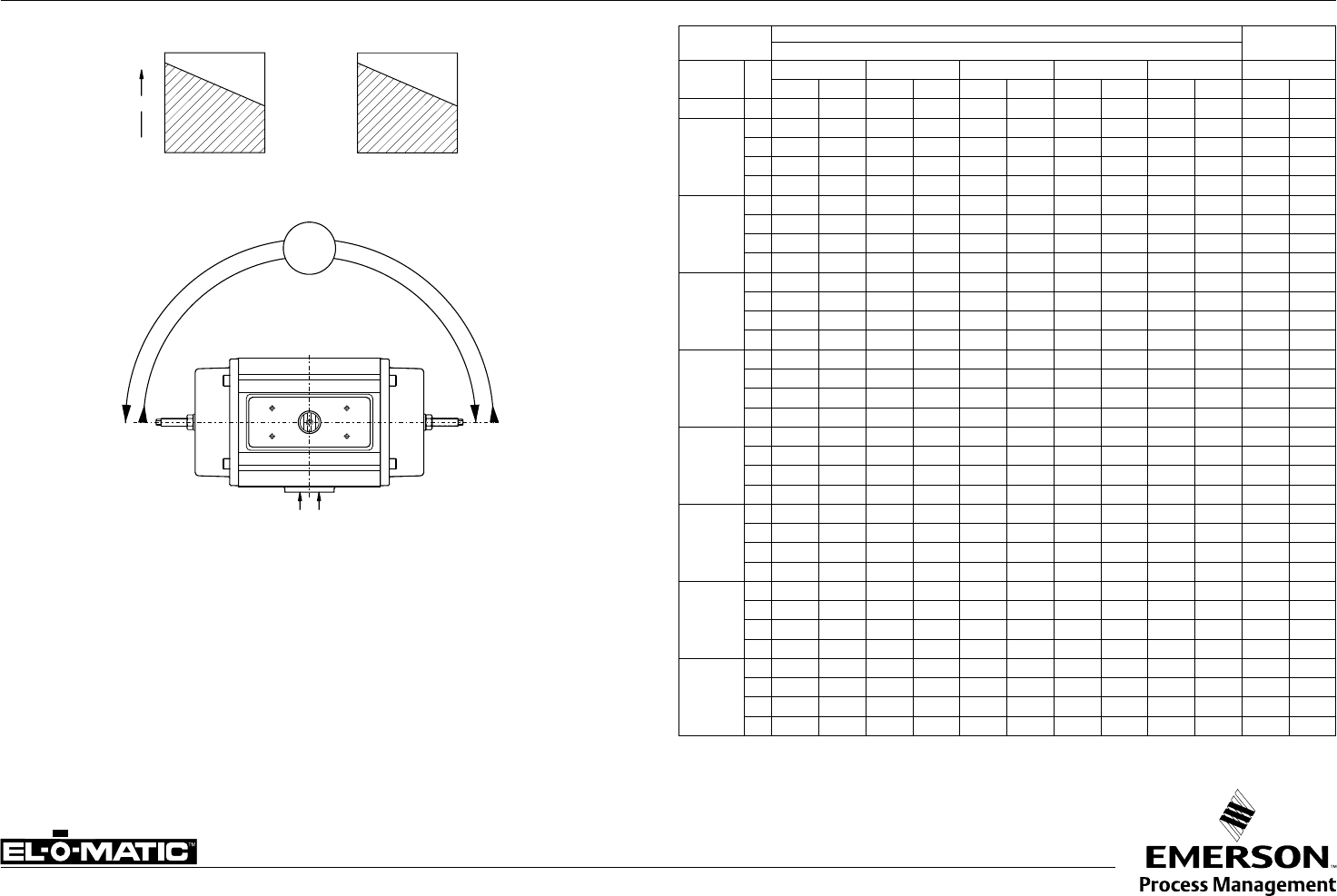
A1.103.106 Rev. D DIMENSION SHEET STANDARD ACTUATOR - ISO E/P
Note
1. Flange and square drive to ISO 5211
2. Top and solenoid flange to VDI/VDE 3845 (NAMUR)
3. For P-series actuators with limit stops see A1.501.01
Dim.
in inch
Actuators E-series P-series
E 12 E 25 E 40 E 65 E100 E150 E200 E 350 E600 E950 E1600 P2500 P4000
A DA 6.26 7.09 7.83 8.70 10.00 11.14 12.01 15.24 16.69 20.31 14.88 19.76
B SR 6.77 8.03 9.80 10.51 12.20 14.17 15.24 18.78 20.35 25.08 22.44 32.83
C3.15 3.66 4.13 4.65 5.51 5.63 7.13 8.66 10.20 11.69 14.02 14.96
D0.79 0.79 0.79 0.79 0.79 0.79 0.79 1.18 1.18 1.18 1.18 1.18
E0.63 0.87 0.87 0.87 1.42 1.42 1.42 2.17 2.17 2.52 2.17 2.52
E2 0.91 1.18 1.18 1.18 1.77 1.77 1.77 2.56 2.56 2.95 2.56 3.15
F0.39 0.55 0.55 0.55 0.75 0.75 0.75 1.42 1.42 1.42 1.42 1.42
G0.47 0.47 0.47 0.47 0.47 0.47 0.47 0.39 0.39 0.39 0.39 0.39
H2.91 3.39 3.86 4.25 4.76 5.04 6.81 8.15 9.09 10.43 13.78 14.96
I1.81 2.09 2.26 2.48 2.76 2.87 3.71 4.45 4.96 5.59 7.28 7.87
J1.26 1.32 1.54 1.59 1.59 1.99 2.85 3.33 4.15 4.74 7.01 7.48
K0.94 1.30 1.30 1.50 2.17 2.17 2.17 2.68 2.95 3.74 3.35 4.72
M1 1.36 1.36 1.36 1.36 1.97 1.97 1.97 2.05 2.52 3.23 2.60 3.03
M2 - - - 1.06 - 1.46 1.46 - - - - -
M3 0.669 0.669 0.669 0.787 0.787 1.161 1.161 1.161 1.949 2.303 - -
N0.04 0.04 0.04 0.06 0.04 0.06 0.06 0.06 0.06 0.06 0.12 0.06
O max. 0.437 0.556 0.556 0.753 0.871 0.871 1.068 1.068 1.424 1.817 1.817 2.173
O min. 0.433 0.551 0.551 0.748 0.866 0.866 1.063 1.063 1.417 1.811 1.811 2.165
P0.555 0.713 0.713 0.992 1.110 1.110 1.425 1.425 1.898 2.370 2.370 2.843
P1 0.555 0.713 0.831 0.909 1.303 1.303 1.303 1.437 1.909 2.382 - -
P2 - - - 0.988 1.264 1.264 1.264 - - - - -
R2.05 2.56 2.76 2.76 3.39 3.54 4.49 4.88 5.12 6.06 6.69 6.69
R1 1.97 1.97 1.97 2.36 2.36 2.36 2.36 3.54 3.54 4.92 6.30 6.30
R2 - - - - - - - - - 5.20 - 10.31
S2.05 2.56 2.76 2.76 3.62 3.54 4.49 4.88 5.59 11.02 11.42 11.42
S1 3.94 3.94 3.94 3.94 3.94 3.94 3.94 6.69 6.69 8.27 9.65 9.65
T1 3.150 3.150 3.150 3.150 3.150 3.150 3.150 5.118 5.118 5.118 5.118 5.118
U1 1.181 1.181 1.181 1.181 1.181 1.181 1.181 1.181 1.181 1.181 1.181 1.181
F03 F05 F05 F05 F07 F07 F07 F10 F10 F16 F16 F16
V1.417 1.969 1.969 1.969 2.756 2.756 2.756 4.016 4.016 6.496 6.496 6.496
W10-24
x.31"
1/4"-20
x.39"
1/4"-20
x.39"
1/4"-20
x.39"
5/16"-18
x.39"
5/16"-18
x.39"
5/16"-18
x.39"
3/8"-16
x.63"
3/8"-16
x.63"
3/4"-10
x1.14"
3/4"-10
x1.14"
3/4"-10
x1.14"
F05 F07 F07 F07 F10 F10 F10 F12 F14 - - F25
V1 1.969 2.756 2.756 2.756 4.016 4.016 4.016 4.921 5.512 - - 10.000
W1 1/4"-20
x.39"
5/16"-18
x.39"
5/16"-18
x.39"
5/16"-18
x.39"
3/8"-16
x.63"
3/8"-16
x.63"
3/8"-16
x.63"
1/2"-13
x.79"
5/8"-11
x.98" - - "5/8""-11
x.98"
For E12 dimensions see data sheet A1.103.102
R
S
S
R2
øK
W1
M1 M2
N ±0.02
øV
O
W
J
A
B
øP2
øP1
E
FG
D
C
E2
H
øK
N ±0.02
øP+0.02
0
øV
O
W
S
R
øV
W1
RR2
T1
U1 R1
S1 A
B
I
øV1
øV1
W
M3
UNC 10-24x.31
0.16
UNC 10-24x.31
1.26
0.95
1/4”NPT
M6x.47
0.16
E-series
E25-E950
E1600
M1
P-series
P2500
P4000
W2
5/8”-11
x .98”
3.827
9.236
øP+0.02
0
T
U

Data sheet
Sheet No.:
Date: November 2009
Copyright © Emerson Process Management. The information in this document is subject to change without notice.
Updated data sheets can be obtained from our website www.El-O-Matic.com or from your nearest Valve Automation Center USA: +1 813 319 0266 Europe: +31 74 256 10 10 Asia-Pacific: +65 6501 4600
www.El-O-matic.com
TM
A1.103.102 Rev. A DIMENSION SHEET ACTUATOR ISO E12 (90°/180°)
TW2
UR1
0.16
UNC10-24x .31
1/4"
E
F
G
D
K1
K
C
E2
W1
X
L
L1
A
B
J
øP+0.02
0
øV
R
W
YI
H
1.77
0.59
MN ±0.02
O
DOUBLE ACTING TORQUE (ED)
Pressure psi 40 50 60 70 80 90 100 120
Torque 90°/180° (in.lb.) 59 74 89 104 119 134 149 179
SINGLE ACTING TORQUE (ES)
Air stroke Spring
stroke
Pressure psi 60 80 100
Position - start end start end start end start end
Torque 90° (in.lb.) 48 23 80 55 112 87 64 41
Torque 180° (in.lb.) 49 25 81 57 112 88 63 40
Dim. in
Inches 90° 180°
A ED 4.06 6.10
B ES 4.65 8.50
C2.36 2.36
D0.79 0.79
E0.63 0.63
E2 0.91 0.91
F0.39 0.39
G0.47 0.47
H2.36 2.36
I1.30 1.30
J0.83 0.83
K0.50 0.50
K1 0.25 0.25
L1.00 1.00
L1 2.00 2.00
M0.65 0.65
N0.039 0.039
Omax. 0.358 0.358
Omin. 0.354 0.354
P0.476 0.476
R1.57 1.57
R1 1.57 1.57
T1.57 1.57
U1.22 1.22
V1.654 1.654
W10-24 UNCx.24" 10-24 UNCx.24"
W1 10-24 UNCx.24" 10-24 UNCx.24"
W2 10-24 UNCx.24" 10-24 UNCx.24"
X1/8"NPT 1/8"NPT
YM6x.48 M6x.48
Data sheet
Copyright © Emerson Process Management. The information in this document is subject to change without notice.
Updated data sheets can be obtained from our website www.El-O-Matic.com or from your nearest Valve Automation Center USA: +1 813 319 0266 Europe: +31 74 256 10 10 Asia-Pacific: +65 6501 4600
www.El-O-matic.com
Sheet No.:
Date: May 2011
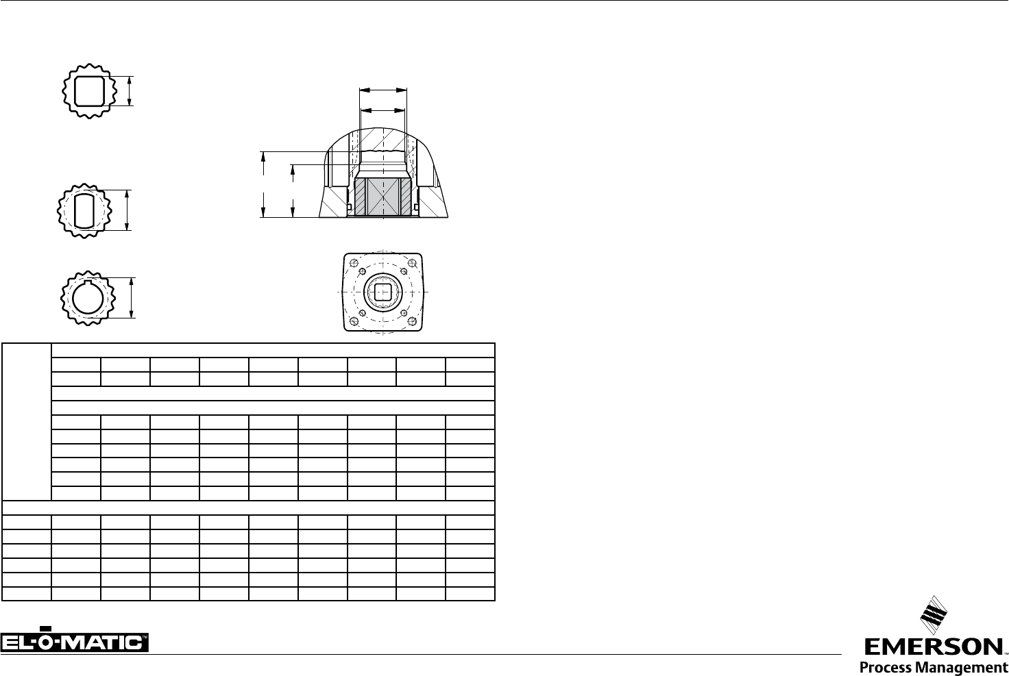
A1.103.200 Rev. B DRIVE INSERTS FOR EL-O-MATIC ACTUATORS E
Description
Most of the El-O-Matic actuators are fitted with drive inserts. This enables actuators to be
directly mounted onto suitable valves and eliminates the need for a bracket and coupling type
mounting kit. The use of direct mounts significantly cuts the cost of the valve/actuator assembly.
Standard actuators are fitted with square drive inserts in accordance with ISO 5211 (or DIN
3337), but a wide variety of other inserts are also available. Special inserts may have oversize or
undersize squares, double-D and shaft key way forms.
Drive inserts can be supplied on factory built actuators or as loose items and are easily
replaceable at distributor or end user level.
Where direct mounts are not possible, for instance on valves with exposed grand packing, the
use of inserts often simplifies the design of the mounting kit.
Material : Aluminum alloy
Finish : Anodized
The following actuator types do not have inserts.
- E12,
- P2500 and P4000
- 180° actuators
These actuators have inner square directly in the bottom of the pinion. See the following data
sheets for more information :
E12 ISO5211 A1.103.102
P2500/P4000 ISO 5211 A1.103.106
180° ISO 5211 A1.203.011
Ø P2
Ø P1
M1 M2
Standard available
insert shapes
Insert mounting
acc. ISO 5211
Optional available
insert shapes
sq Max.
D Max.
D Max.
Standard inserts with inner-square-dimensions per actuator type
E25 E40 / E65 E100 E150 E200 E350 E600 E950 E1600
0.433 0.551 0.748 0.866 0.866 1.063 1.063 1.417 1.811
Optional insert dimensions
0.354 0.394 0.472 0.551 0.551 0.551 0.551 0.866
0.394 0.472 0.551 0.630 0.630 0.630 0.630
0.63 0.669 0.669 0.669 0.669
0.748 0.748 0.748 0.748
0.945 0.945 0.866 0.866
1.063 1.063 0.945 0.945
Maximum insert dimensions
M1 1.36 1.36 1.36 1.97 1.97 1.97 2.05 2.52 3.23
M2 - - 1.06 1.46 1.46 1.46 - - -
P1 0.71 0.71 0.91 1.26 1.26 1.26 1.44 1.91 2.38
P2 - - 0.99 1.43 1.43 1.43 - - -
SQ max. 0.630 0.630 0.748 1.063 1.063 1.063 1.063 1.417 1.811
D max. 0.827 0.827 0.929 1.323 1.323 1.323 1.323 1.772 2.362
Data sheet
Sheet No.:
Date: January 2010
Copyright © Emerson Process Management. The information in this document is subject to change without notice.
Updated data sheets can be obtained from our website www.El-O-Matic.com or from your nearest Valve Automation Center USA: +1 813 319 0266 Europe: +31 74 256 10 10 Asia-Pacific: +65 6501 4600
www.El-O-matic.com
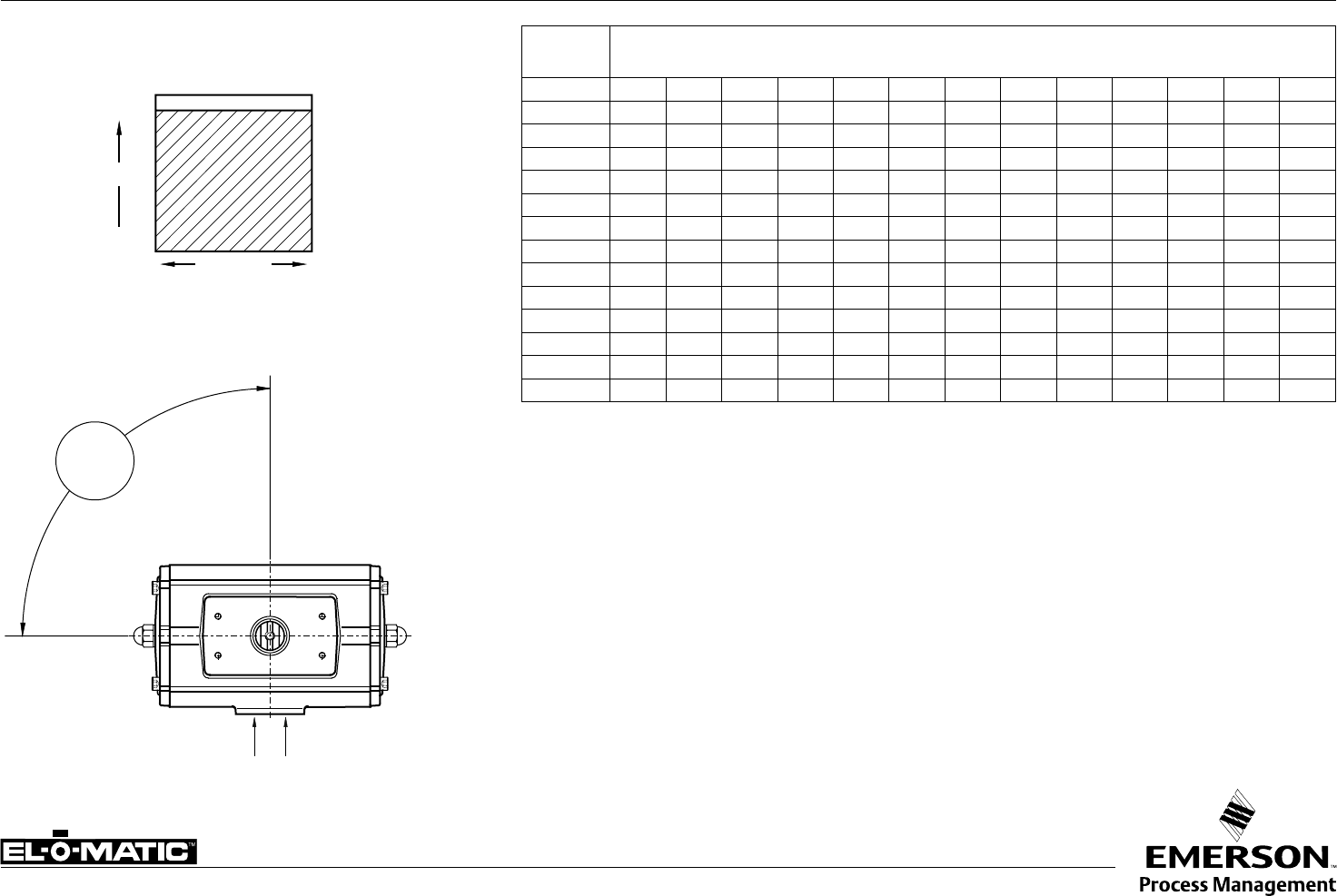
A1.104.01 Rev. B DOUBLE ACTING ACTUATOR TORQUE (In.lb.) 90°
Actuator Torque of double acting actuators (in In.lb)
Supply pressure (psi)
Type Size 30 35 40 45 50 55 60 70 75 80 90 100 120
ED 12 43.9 51.4 58.9 66.4 73.9 81.4 88.9 104 111 119 134 149 179
ED 25 81.4 95.3 109 123 137 151 165 193 206 220 248 276 332
ED 40 153 179 205 231 257 283 309 361 387 413 466 518 622
ED 65 233 272 312 352 392 431 471 551 590 630 709 789 948
ED 100 344 402 461 520 578 637 696 813 872 930 1048 1165 1400
ED 150 551 645 739 833 927 1021 1115 1303 1397 1491 1680 1868 2244
ED 200 754 883 1011 1140 1269 1398 1527 1784 1913 2042 2299 2557 3072
ED 350 1310 1534 1757 1981 2205 2428 2652 3100 3323 3547 3994 4442 5337
ED 600 2226 2606 2986 3366 3747 4127 4507 5267 5647 6028 6788 7548 9069
ED 950 3323 3890 4458 5025 5593 6160 6728 7862 8430 8997 10132 11267 13537
ED 1600 5493 6431 7369 8307 9245 10183 11121 12998 13936 14874 16750 18626 22379
PD 2500 8774 10273 11825 13270 14768 16267 17847 20858 22363 23869 26880 29891 35912
PD 4000 14874 17414 19962 22495 25035 27576 30127 35210 37751 40293 45375 50458 60623
Note
1. Emerson Process Management recommends that the valve manufacturer supply the maximum required torque
values (Including any adjustments or suggested safety factors for valve service conditions or application).
Additionally, the valve manufacturer must identify at which position(s) and direction(s) of rotation
(Counter Clock Wise or Clock Wise) these maximum requirements occur.
2. If in doubt, or you require any assistance with sizing actuators, do not hesitate to contact your
nearest Emerson's Valve Automation Division representative.
3 Pressure on port "A" opens the actuator*
4 The actuator is shown in closed position*
(* code A, data sheet A1.503)
91.5°
-0.5°
91°
AB
CLOSED
OPEN
Rotation
Start End
Torque
DOUBLE ACTING TORQUE
Data sheet
Sheet No.:
Date: January 2010
Copyright © Emerson Process Management. The information in this document is subject to change without notice.
Updated data sheets can be obtained from our website www.El-O-Matic.com or from your nearest Valve Automation Center USA: +1 813 319 0266 Europe: +31 74 256 10 10 Asia-Pacific: +65 6501 4600
www.El-O-matic.com
A1.104.02 Rev. B SPRING RETURN ACTUATOR TORQUE (In.lb.) 90°
Springset
nr.
Air Stroke (lbf/in) Spring Stroke
SUPPLY PRESSURE (in PSI)
Actuator
Type
40 60 80 100 120 (lbf/in)
CDCDCDCDCDEF
ES 12 2 - - 48 24 80 55 111 87 143 119 63 40
ES 25 2
3
4
5
6
71 44 130 103 189 162 248 221 306 280 62 39
48 8 107 67 166 126 225 185 284 244 94 59
- - 85 31 144 90 203 149 262 208 125 78
- - - - 121 54 180 113 239 172 156 98
- - - - 99 18 158 77 217 136 188 117
ES 40 2 133 82 243 193 354 303 464 414 575 524 117 73
3 91 15 201 125 312 236 422 346 533 457 176 110
4 - - 159 58 270 169 380 279 491 390 234 146
5 - - - - 228 101 338 212 449 322 293 183
6 - - - - 185 34 296 144 406 255 351 220
ES 65 2 196 117 365 285 533 454 701 622 870 790 186 117
3 129 10 297 178 466 347 634 515 802 683 279 176
4 - - 230 71 398 240 567 408 735 576 372 234
5 - - - - 331 133 500 301 668 470 465 292
6 - - - - 264 26 432 194 601 363 558 351
ES 100 2 303 192 552 441 801 690 1050 939 1299 1188 258 161
3 211 44 460 293 709 542 958 791 1206 1039 387 242
4 - - 367 144 616 393 865 642 1114 891 516 323
5 - - - - 523 245 772 494 1021 743 646 403
6 - - - - 430 96 679 345 928 594 775 484
ES 150 2 485 297 884 696 1283 1094 1681 1493 2080 1892 423 259
3 337 54 735 453 1134 852 1533 1250 1931 1649 634 388
4 - - 587 210 985 609 1384 1007 1783 1406 845 517
5 - - - - 837 366 1235 764 1634 1163 1056 647
6 - - - - 688 123 1087 522 1485 920 1268 776
ES 200 2 656 406 1202 952 1747 1498 2293 2043 2838 2589 579 362
3 448 74 994 619 1539 1165 2085 1710 2631 2256 868 542
4 - - 786 287 1332 832 1877 1378 2423 1924 1158 723
5 - - - - 1124 500 1669 1045 2215 1591 1447 904
6 - - - - 916 167 1462 713 2007 1258 1736 1085
ES 350 2 1105 684 2053 1632 3001 2580 3949 3528 4897 4476 1025 658
3 727 95 1675 1043 2623 1991 3571 2939 4519 3887 1537 987
4 - - 1297 455 2245 1403 3193 2351 4141 3299 2049 1317
5 - - - - 1866 814 2814 1762 3762 2710 2561 1646
6 - - - - 1488 225 2436 1173 3384 2121 3074 1975
ES 600 2 1920 1183 3531 2794 5142 4405 6753 6016 8364 7628 1723 1082
3 1298 193 2909 1804 4520 3415 6131 5026 7742 6637 2585 1624
4 - - 2287 814 3898 2425 5509 4036 7120 5647 3446 2165
5 - - - - 3276 1434 4887 3046 6498 4657 4308 2706
6 - - - - 2654 444 4265 2055 5876 3666 5169 3247
ES 950 2 2898 1777 5303 4182 7708 6587 10113 8992 12518 11397 2563 1587
3 1986 304 4391 2709 6796 5114 9201 7519 11606 9924 3844 2381
4 - - 3479 1236 5884 3641 8288 6046 10693 8451 5125 3175
5 - - - - 4971 2168 7376 4573 9781 6978 6407 3968
6 - - - - 4059 695 6464 3100 8869 5505 7688 4762
ES 1600 2 4765 2988 8741 6964 12716 10939 16692 14915 20668 18890 4193 2646
3 3244 578 7220 4554 11196 8530 15171 12505 19147 16481 6289 3970
4 - - 5699 2145 9675 6120 13650 10096 17626 14071 8385 5293
5 - - - - 8154 3711 12129 7686 16105 11662 10481 6616
6 - - - - 6633 1301 10608 5277 14584 9252 12578 7939
Springset
nr.
Air Stroke (lbf/in) Spring Stroke
SUPPLY PRESSURE (in PSI)
Actuator
Type
40 60 80 100 120 (lbf/in)
CDCDCDCDCDEF
PS 2500 6 6881 4278 12875 10273 18869 16267 24863 22261 30858 28255 7013 4401
8 5251 1781 11245 7775 17239 13769 23233 19764 29228 25758 9351 5868
10 - - 9615 5278 15609 11272 21603 17266 27597 23260 11689 7335
12 - - 7985 2780 13979 8774 19973 14768 25967 20763 14026 8803
14 - - - - 12349 6277 18343 12271 24337 18265 16364 10270
PS 4000 6 11701 7310 21862 17472 32024 27633 42185 37795 52347 47956 11835 7429
8 8949 3096 19111 13257 29272 23419 39434 33580 49595 43742 15780 9905
10 - - 16359 9042 26521 19204 36682 29365 46844 39527 19725 12381
12 - - 13608 4828 23770 14989 33931 25150 44093 35312 23670 14857
14 - - - - 21018 10774 31180 20936 41341 31097 27615 17333
SINGLE ACTING TORQUE
91.5°
C
F
D E
-0.5°
91°
AB
OPEN
CLOSED
F
End
Rotation
Clockwise
D
End
Rotation
Counter Clockwise
C
Start
SPRING STROKEAIR STROKE
Torque
E
Start
Note
1. Emerson Process Management
recommends that the valve manufacturer
supply the maximum required torque values
(Including any adjustments or suggested
safety factors for valve service conditions or
application).
Additionally, the valve manufacturer must
identify at which position(s) and direction(s)
of rotation (Counter Clock Wise or Clock
Wise) these maximum requirements occur.
2. If in doubt, or you require any assistance
with sizing actuators, do not hesitate to
contact your nearest Emerson's Valve
Automation Division representative.
3 Pressure on port "A" opens the actuator*
4 The actuator is shown in closed position*
(* code A, data sheet A1.504)
Data sheet
Sheet No.:
Date: November 2009
Copyright © Emerson Process Management. The information in this document is subject to change without notice.
Updated data sheets can be obtained from our website www.El-O-Matic.com or from your nearest Valve Automation Center USA: +1 813 319 0266 Europe: +31 74 256 10 10 Asia-Pacific: +65 6501 4600
www.El-O-matic.com
TM
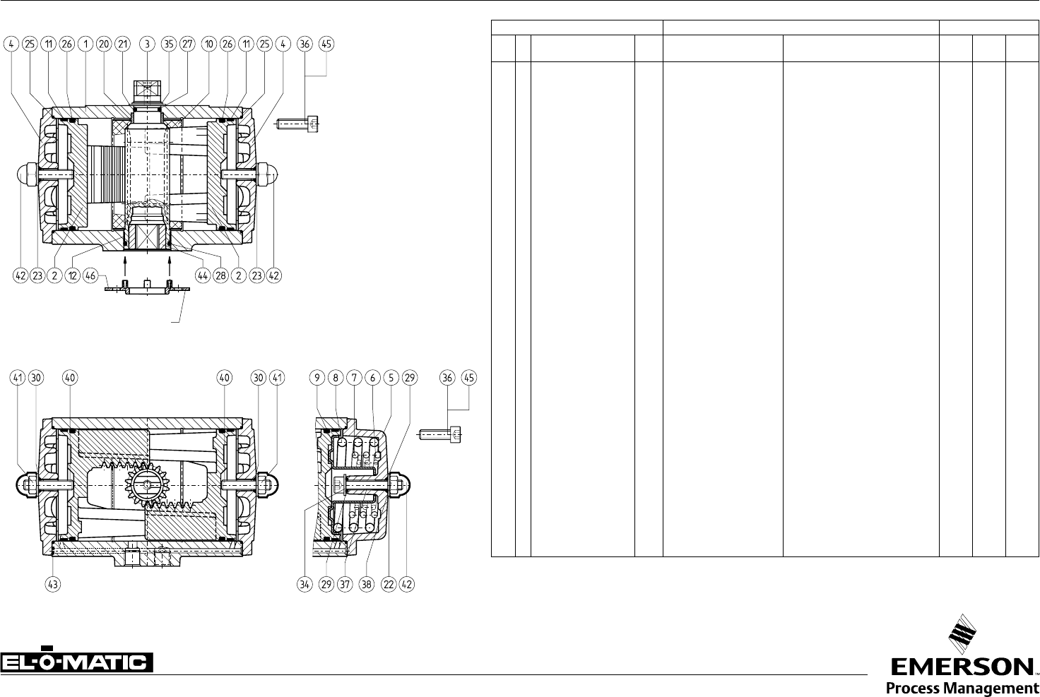
A1.101.33 Rev. A CONSTRUCTION, PARTS AND MATERIALS E-SERIE ACTUATORS E
Parts Materials Excecutions
Nr. Description Qty. Description Specification Std S.S.
Shaft CSR
1 Body 1 Aluminum Alloy UNS A13600, ASTM B85 - - 5
2 Piston 2 Aluminum Alloy UNS A03560, ASTM B26 - - -
3 Drive pinion 1 GAlSi10Mg, DIN 1725/2 UNS 1 77075, ASTM 7075 T6 1 6 6
4 End Cap ED 2 Aluminum Alloy UNS A13600, ASTM B85 - - 5
5 End Cap ES 2 Aluminum Alloy UNS A13600, ASTM B85 - - 5
6 Spring- inner 2 Carbon Spring Steel UNS G10860, ASTM A228 2 2 2
7 Spring- mid 2 Carbon Spring Steel UNS G10860, ASTM A228 2 2 2
8 Spring- outer 2 Carbon Spring Steel UNS G10860, ASTM A228 2 2 2
9 Spring Holder 2 Steel C45, DIN 17200 3 3 3
10 * Guide Band 1 Nylatron PA6.6 + MoS2 - - -
11 * Guide Band 2 PTFE, Carbon filled PTFE + 25% C - - -
12 * Bearing Bush 1 Nylatron PA6.6 + MoS2 - - -
20 * Bearing Bush 1 Delrin POM - - -
21 * O-ring 1 Nitrile Rubber Buna N - - -
22 * Washer ES 2 Nylon PA6 - - -
23 * Washer ED 2 Nylon PA6 - - -
25 * O-ring 2 Nitrile Rubber Buna N - - -
26 * O-ring 2 Nitrile Rubber Buna N - - -
27 * Washer 1 ZEDEX 100 K - - - -
28 * O-ring 1 Nitrile Rubber Buna N - - -
29 * O-ring 4 Nitrile Rubber Buna N - - -
30 * O-ring 2 Nitrile Rubber Buna N - - -
34 Washer ES 2 Steel C35 3 3 3
35 * Spring Clip 1 Carbon Spring Steel MIL - R-212 48B 2 7 7
36 End Cap Bolt ED/ES 8 Stainless Steel AISI 304 - - -
37 Limit Stop Bolt ES 2 Stainless Steel AISI 304 - - -
38 Nut 2 Stainless Steel AlSl 304 - - -
40 Limit Stop Bolt ED 2 Stainless Steel AISI 304 - - -
41 Nut 2 Stainless Steel AISI 304 - - -
42 Nut Cover 2 Polyethylene PE - - -
43 * O-ring 2 Nitrile Rubber Buna N - - -
44 Insert 1 Aluminum Alloy UNS 1 6082, ASTM 6082 4 9 4
45 Threaded insert 8 Steel UNS G10430, ASTM A29 3 3 3
* Recommended spare parts (contained in Repair kits)
Notes
1 Hard anodized
aluminum alloy:
AlZnMgCu1.5,
DIN 1725/1
2 Deltatone Coating
3 Anodized
4 Zinc plated and
passivated
5 CSR Coating
(see 4.204.02)
6 Stainless Steel
Sandvic 1802, SS2382
7 Stainless Steel
X35CrM017
8 No insert, adaptor
square direct in pinion
Optional center-plate
DOUBLE ACTING ED SINGLE ACTING ES
Remark
All materials are European origin, listed are the nearest US equivalents.
Finish
Standard : Polyester non-TGIC based powder coating
(see data sheet A4.204.01)
CSR : CSR Coating (see data sheet A4.204.02)

Data sheet
Sheet No.:
Date: November 2009
Copyright © Emerson Process Management. The information in this document is subject to change without notice.
Updated data sheets can be obtained from our website www.El-O-Matic.com or from your nearest Valve Automation Center USA: +1 813 319 0266 Europe: +31 74 256 10 10 Asia-Pacific: +65 6501 4600
www.El-O-matic.com
TM
Notes
1 Hard anodized
2 Deltatone® Coating
3 Zinc plated and passivated
4 Stainless Steel AISI 304
5 Stainless Steel, X35CrM017
6 CSR Coating (see A4.204.02)
7 P4000 has a stainless steel (AISI 304)
locking ring between spring clip (20)
and thrust washer (21)
8 P4000 has in the springs a guiding bush (PVC)
Remark
All materials are European origin, listed are the nearest US equivalents
Finish
Standard : Polyester non-TGIC based powder coating
(see data sheet A4.204.01)
CSR : CSR Coating (see data sheet A4.204.02)
Parts Materials Excecutions
Nr. Description Qty. Description Specification Std S.S.
Shaft CSR
1 Body 1 Aluminum Alloy UNS A13600, ASTM B85 - - 6
2 Piston 2 Aluminum Alloy UNS A03560, ASTM B26 - - -
3 Endcap PDA 2 Aluminum Alloy UNS A13600, ASTM B85 - - 6
4 Endcap PSA 2 Aluminum Alloy UNS A13600, ASTM B85 - - 6
5 Drive pinion 1 Aluminum Alloy UNS 1 77075, ASTM 7075 T6 1 4 4
6 Gear Rack 2 Steel UNS G10950, ASTM A108 - - -
8 Spring 14 Carbon Spring Steel UNS G10860, ASTM A228 2 2 2
9 * Bearing Bush 1 Nylatron GS PA6.6 + MoS2 - - -
10 * Bearing Bush 1 Delrin POM - - -
14 * Guide band 2 PTFE, Carbon filled PTFE + 25% C - - -
15 * Guide band 2 PTFE, Carbon filled PTFE + 25% C - - -
16 * O-ring 2 Nitrile Rubber Buna N - - -
17 * O-ring 2 Nitrile Rubber Buna N - - -
18 * O-ring 1 Nitrile Rubber Buna N - - -
19 * O-ring 1 Nitrile Rubber Buna N - - -
20 * Spring Clip 1 Carbon Spring Steel MIL - R-212 48B 2 5 5
21 * Thrust Washer 1 ZEDEX 100 K - - - -
23 Bolt 4 Alloy Steel 12.9 ASTM F568 - - -
24 Endcap bolt PDA 20 Alloy Steel 8.8 ASTM F568 2 4 4
25 Endcap bolt PSA 20 Alloy Steel 8.8 ASTM F568 2 4 4
26 * O-ring 2 Nitrile Rubber Buna N - - -
27 Threaded insert 20 Steel UNS G10430, ASTM A29 3 3 3
* Recommended spare parts (contained in Repair kit)
DOUBLE ACTING PD SINGLE ACTING PS
A1.101.30 Rev. A CONSTRUCTION, PARTS AND MATERIALS P-SERIE ACTUATORS P
Data sheet
Sheet No.:
Date: November 2009
Copyright © Emerson Process Management. The information in this document is subject to change without notice.
Updated data sheets can be obtained from our website www.El-O-Matic.com or from your nearest Valve Automation Center USA: +1 813 319 0266 Europe: +31 74 256 10 10 Asia-Pacific: +65 6501 4600
www.El-O-matic.com
TM
5
6
8
10
12
13
14
12 3
47 9
11
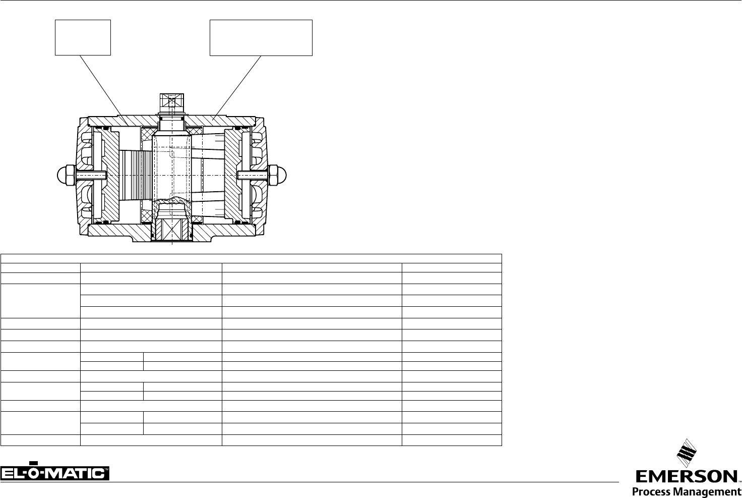
A1.101.60 Rev. A CONSTRUCTION, PARTS AND MATERIALS DSA ACTUATOR
Nr. Description Qty. Material Specification Note
1 Body DSA 1 Aluminum Alloy UNS A13600, ASTM B85 -
2 Piston DSA 2 Aluminum Alloy UNS A03560, ASTM B26 -
3 Drive pinion DSA 1 Aluminum Alloy UNS 1 77075, ASTM 7075 T6 1
4 * Guide Band DSA 1 Nylatron GS UNS A13600, ASTM B85 -
5 Cam for stroke adj. DSA 1 Stainless Steel UNS A13600, ASTM B85 -
6 Shaftpin for stroke adj. DSA 1 Chrome nickel steel UNS G10860, ASTM A228 -
7 * Washer 1 ZEDEX 100 K - -
8 * Washer 1 Nylon UNS G10860, ASTM A228 -
9 * O-ring shaft top 1 Nitrile Rubber C45, DIN 17200 -
10 * O-ring limit stop bolt DSA 1 Nitrile Rubber PA6.6 + MoS2 -
11 Circlip 1 Carbon spring steel PTFE + 25% C 2
12 Limitstop bolt DSA 1 Stainless Steel PA6.6 + MoS2 -
13 Nut 1 Stainless Steel POM -
14 Nut Cover 1 Polyethylene Buna N -
* Recommended spare parts (contained in Repair kits DSA)
Finish
Polyester non-TGIC based powder coating (see data sheet A4.204.01)
Note
1 Hard anodized
2 Deltatone® coating
Remark
This data sheet shows only the extra or specific parts of a DSA actuator.
For all the other parts see data sheet A1.101.33
DSA

Data sheet
Copyright © Emerson Process Management. The information in this document is subject to change without notice.
Updated data sheets can be obtained from our website www.El-O-Matic.com or from your nearest Valve Automation Center USA: +1 813 319 0266 Europe: +31 74 256 10 10 Asia-Pacific: +65 6501 4600
www.El-O-matic.com
Sheet No.:
Date: June 2010
A1.101.70 Rev. C LOW TEMPERATURE ACTUATOR SPECIFICATIONS
-40°C / +80°C
-40°F / +176°F
Silicone
MVQ 70
Sealings
Castrol Optitemp TT1
Low Temperature
Grease
Materials
Part Material Specifications Remark
Housing Aluminum Alloy UNS A13600, ASTM B85
Drive Shaft
Aluminum Alloy UNS 1 77075, ASTM 7075 T6 Hard anodized
Steel (180° rotation) ETG100 or 42CrMo4V XM Zinc Plated type > P750
Stainless Steel Sandvic 1802, SS2382 or X35CrM017 type > E950
Piston Aluminum Alloy UNS A03560, ASTM B26
Sealings Silicone MVQ 70 O-rings -/-
Grease Castrol Optitemp TT1 -/-
Shaft bearings Top : Delrin POM
Bottom : Nylatron PA6.6 + MoS2
Piston bearings PTFE 25% Carbon filled
Bodybearings PTFE (“P” serie) 25% Carbon filled
Nylatron (“E” serie) PA6.6 + MoS2
Shaft thrust washer ZEDEX 100 K -/-
End cap bolts Stainless Steel (“E” serie) AISI 304 A2
Alloy Steel (“P” serie) 8.8 DIN 912 Deltatone® coating
Springs Carbon Spring Steel UNS G10860, ASTM A228 Deltatone® coating
Description
A double piston, rack and pinion pneumatic actuator incorporating a three point piston support
system, anti-blowout spindle and with high duty synthetic bearings at all bearing points.
This version is a standard aluminum actuator, but incorporating parts and materials suitable for
low temperature operation.
Note
When operating actuators in sub-zero temperatures (< 0°C or < 32°F) care should be taken to
counter the effects of freezing condensate inside the actuator.
Specification
Max. pressure : 120 psi (8 bar)
Torque : Standard
Media : Air or non corrosive gas
Temperature : -40°F to +176°F (-40°C to +80°C)
Finish : Polyester non-TGIC based powder coating (see data sheet A4.204.01)
Spare parts
Dedicated low temperature spare parts are available for maintenance or make a standard
actuator suiteable for low temperature operation.
Data sheet
Copyright © Emerson Process Management. The information in this document is subject to change without notice.
Updated data sheets can be obtained from our website www.El-O-Matic.com or from your nearest Valve Automation Center USA: +1 813 319 0266 Europe: +31 74 256 10 10 Asia-Pacific: +65 6501 4600
www.El-O-matic.com
Sheet No.:
Date: January 2010
A1.101.71 Rev. B HIGH TEMPERATURE ACTUATOR SPECIFICATIONS
-20°C / +120°C
-4°F / +248°F
Viton
FPM
Sealings
Castrol
LMX
Grease
Description
A double piston, rack and pinion pneumatic actuator incorporating a three point piston support
system, anti-blowout spindle and with high duty synthetic bearings at all bearing points.
This version is a standard aluminum actuator, but incorporating parts and materials suitable for
high temperature operation.
Specification
Max. pressure : 8 bar ~ 120psi
Torque : Standard
Media : Air or non corrosive gas
Temperature : -4°F to +248°F (-20°C to +120°C)
Finish : Polyester non-TGIC based powder coating (see data sheet A4.204.01)
Spare parts
Dedicated high temperature spare parts are available for maintenance or make a standard
actuator suiteable for high temperature operation.
Materials
Part Material Specifications Remark
Housing Aluminum Alloy UNS A13600, ASTM B85
Drive Shaft
Aluminum Alloy UNS 1 77075, ASTM 7075 T6 Hard anodized
Steel (180° rotation) ETG100 or 42CrMo4V XM Zinc Plated type > P750
Stainless Steel Sandvic 1802, SS2382 or X35CrM017 type > E950
Piston Aluminum Alloy UNS A03560, ASTM B26
Sealings Viton FPM O-rings -/-
Grease Castrol LMX -/-
Shaft bearings Top : Delrin POM
Bottom : Nylatron PA6.6 + MoS2
Piston bearings PTFE 25% Carbon filled
Bodybearings PTFE (“P” serie) 25% Carbon filled
Nylatron (“E” serie) PA6.6 + MoS2
Shaft thrust washer ZEDEX 100 K -/-
End cap bolts Stainless Steel (“E” serie) AISI 304 A2
Alloy Steel (“P” serie) 8.8 DIN 912 Deltatone® coating
Springs Carbon Spring Steel UNS G10860, ASTM A228 Deltatone® coating
Data sheet
Sheet No.:
Date: November 2009
Copyright © Emerson Process Management. The information in this document is subject to change without notice.
Updated data sheets can be obtained from our website www.El-O-Matic.com or from your nearest Valve Automation Center USA: +1 813 319 0266 Europe: +31 74 256 10 10 Asia-Pacific: +65 6501 4600
www.El-O-matic.com
TM
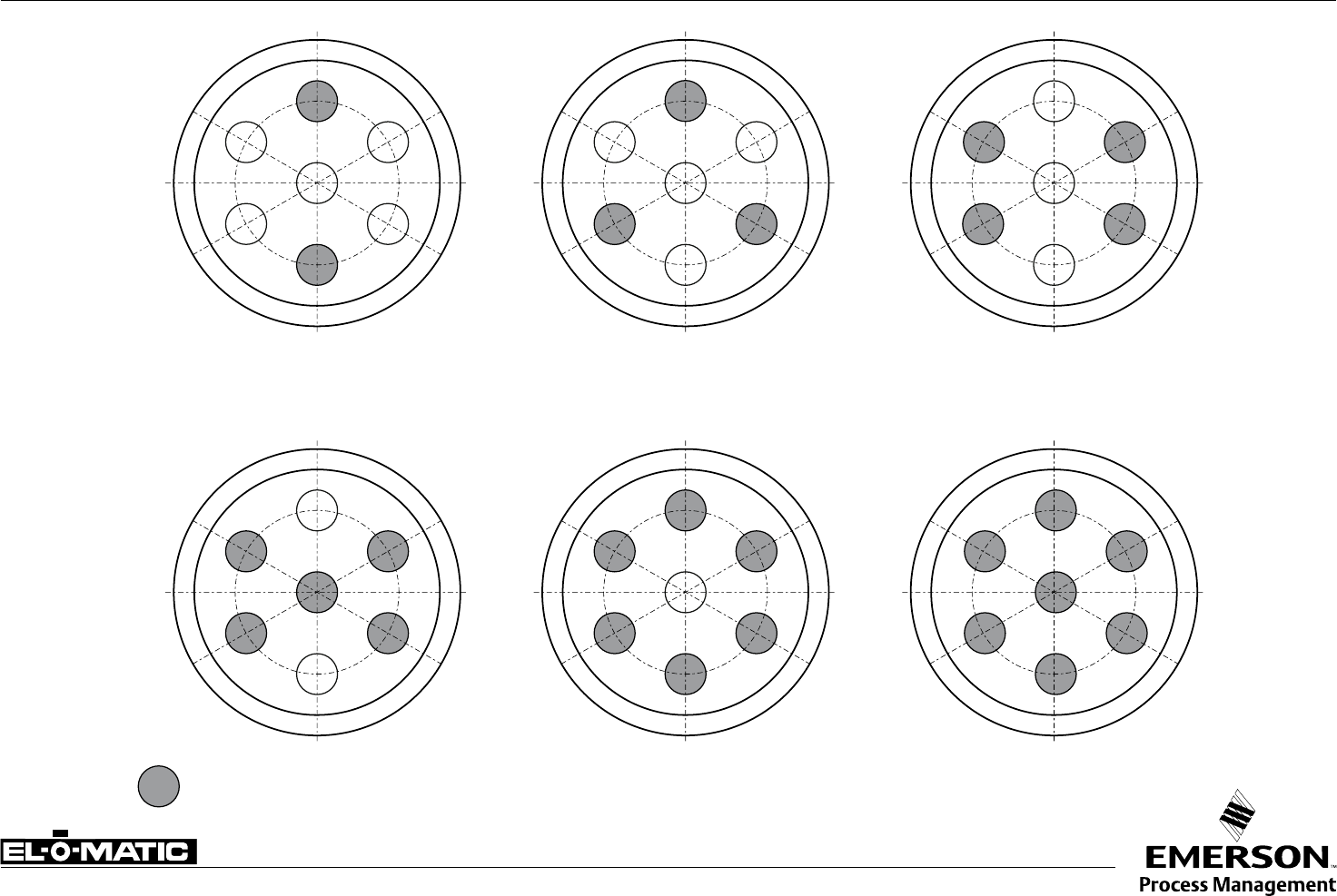
A4.201 Rev.A INSTALLATION OF SPRINGS OF P-SERIES ACTUATOR P
4 SPRINGS 6 SPRINGS 8 SPRINGS
10 SPRINGS 12 SPRINGS 14 SPRINGS
SPRING
Data sheet
Sheet No.:
Date: November 2009
Copyright © Emerson Process Management. The information in this document is subject to change without notice.
Updated data sheets can be obtained from our website www.El-O-Matic.com or from your nearest Valve Automation Center USA: +1 813 319 0266 Europe: +31 74 256 10 10 Asia-Pacific: +65 6501 4600
www.El-O-matic.com
TM
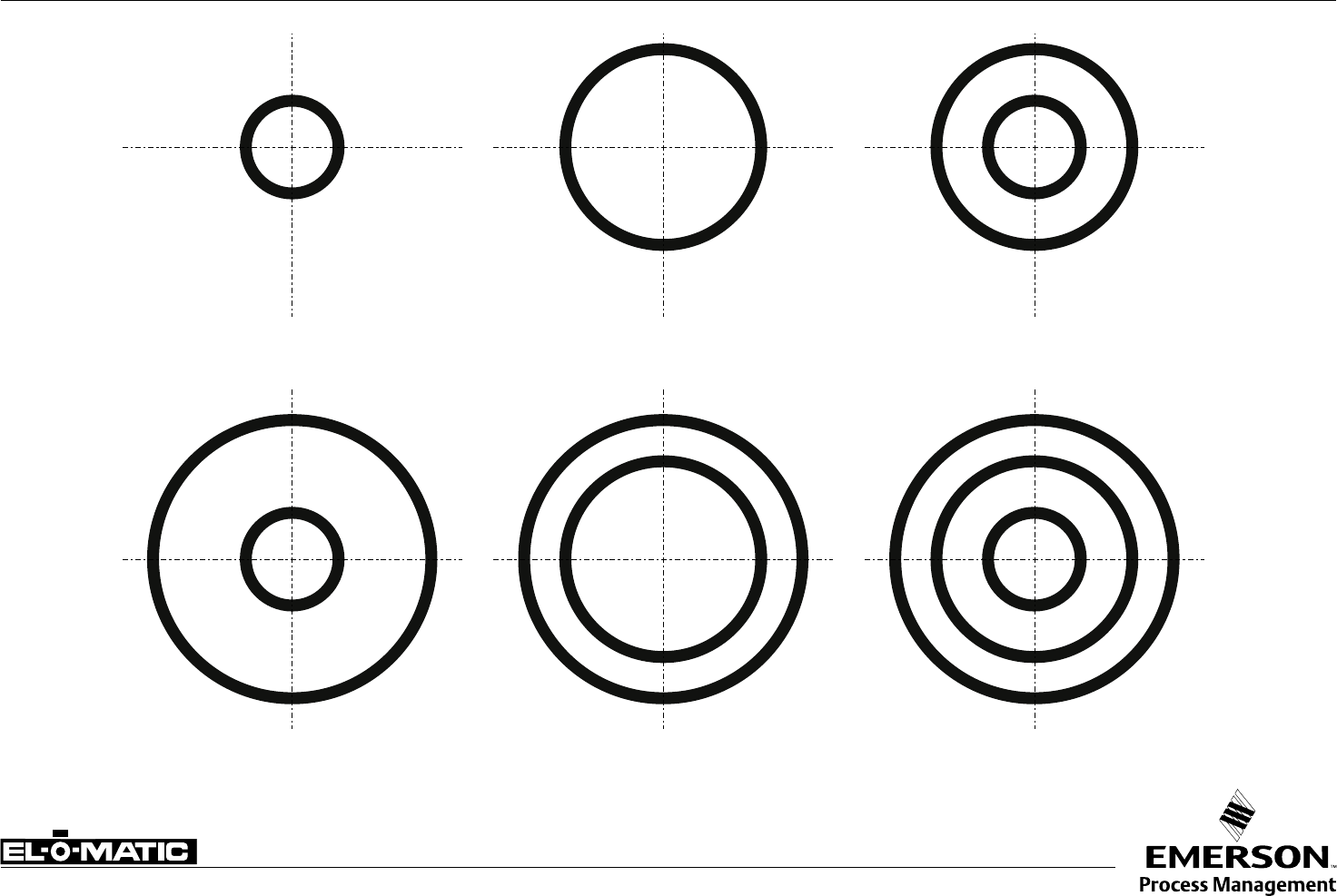
SPRING SET No. 4
inner spring
outer spring
SPRING SET No. 1
inner spring
SPRING SET No. 2
mid spring
SPRING SET No. 5
mid spring
outer spring
SPRING SET No. 6
inner spring
mid spring
outer spring
SPRING SET No. 3
inner spring
mid spring
A4.202 Rev.A INSTALLATION OF SPRINGS OF E-SERIES ACTUATOR E
Data sheet
Sheet No.:
Date: November 2009
Copyright © Emerson Process Management. The information in this document is subject to change without notice.
Updated data sheets can be obtained from our website www.El-O-Matic.com or from your nearest Valve Automation Center USA: +1 813 319 0266 Europe: +31 74 256 10 10 Asia-Pacific: +65 6501 4600
www.El-O-matic.com
TM
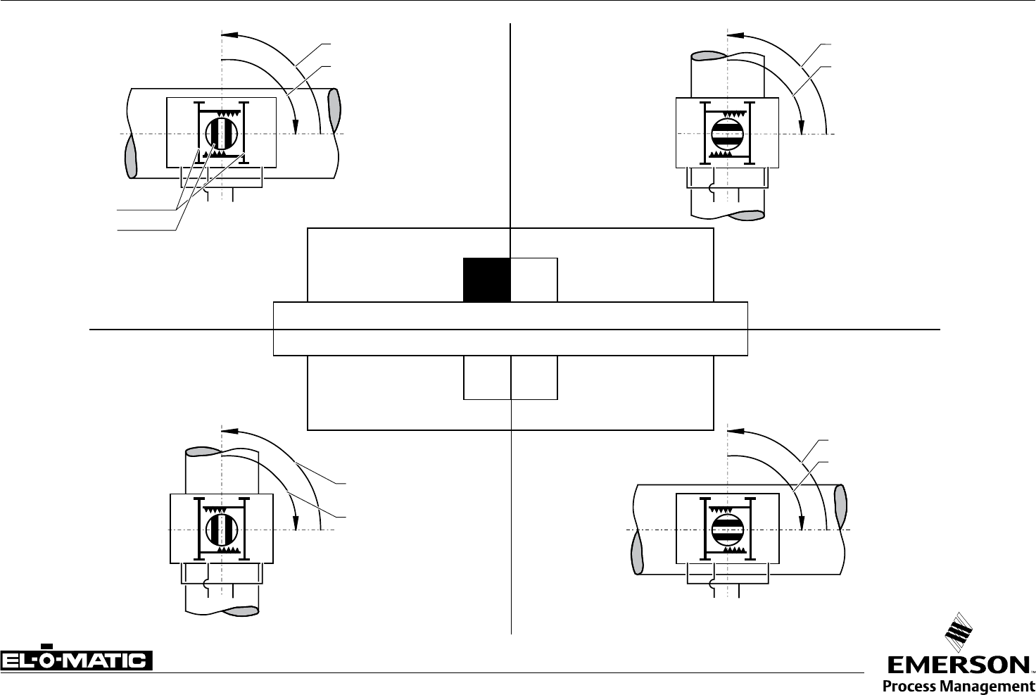
A1.503 Rev. A DOUBLE ACTING ACTUATOR ASSEMBLY MODES E/P
AB
AB
AB
AB
A-port pressurized
B-port pressurized
Pistons
Shaft
A-port pressurized
B-port pressurized
B-port pressurized
A-port pressurized
B-port pressurized
A-port pressurized
B
SHAFT TURNED 90°
(from standard)
STANDARD
DC
MOUNTING ACROSS LINE
MOUNTING IN LINE
MOUNTING IN LINE
MOUNTING ACROSS LINE
SHAFT TURNED 90°
PISTONS TURNED 180°
(from standard)
PISTONS TURNED 180°
(from standard)
(OPTIONAL L1/LF) LIMIT STOPS WILL ADJUST THE VALVE AT OPEN POSITION
(OPTIONAL L1/LF) LIMIT STOPS WILL ADJUST THE VALVE AT CLOSED POSITION
All views are from above
Pistons are shown in inner position
A
Data sheet
Sheet No.:
Date: November 2009
Copyright © Emerson Process Management. The information in this document is subject to change without notice.
Updated data sheets can be obtained from our website www.El-O-Matic.com or from your nearest Valve Automation Center USA: +1 813 319 0266 Europe: +31 74 256 10 10 Asia-Pacific: +65 6501 4600
www.El-O-matic.com
TM
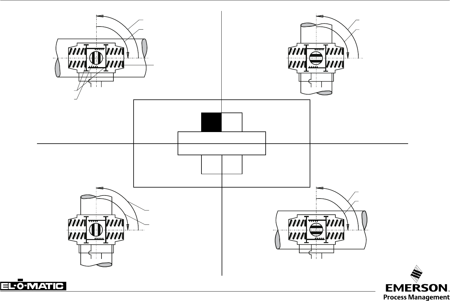
A1.504 Rev. A SPRING RETURN ACTUATOR ASSEMBLY MODES E/P
AB
AB
AB
AB
SPRING TO OPEN (ROTATION CCW)
B
SHAFT TURNED 90°
(from standard)
STANDARD
DC
MOUNTING ACROSS LINE
MOUNTING IN LINE
MOUNTING IN LINE
MOUNTING ACROSS LINE
SHAFT TURNED 90°
PISTONS TURNED 180°
(from standard)
PISTONS TURNED 180°
(from standard)
SPRING TO CLOSE (ROTATION CW)
A-port pressurized
Spring stroke
Springs
Pistons
Shaft
A-port pressurized
Spring stroke
A-port pressurized
Spring stroke
Spring stroke
A-port pressurized
A
All views are from above
Pistons are shown in inner position
Data sheet
Copyright © Emerson Process Management. The information in this document is subject to change without notice.
Updated data sheets can be obtained from our website www.El-O-Matic.com or from your nearest Valve Automation Center USA: +1 813 319 0266 Europe: +31 74 256 10 10 Asia-Pacific: +65 6501 4600
www.El-O-matic.com
Description
The corrosion protection system of standard El-O-Matic E&P series pneumatic actuators consist of the
following treatments or materials:
1 De-greasing
All aluminum parts are de-greased before the powder coating is applied by washing with an alkaline
solution to assure the best bonding between the aluminum surface and the coating.
2 Powder coating
- Polyester non-TGIC based powder coating for exterior use.
- The powder coating is applied cold using automatic electrostatic spray equipment and is cured at
minimum 190°C (374°F) offering excellent anti color fade and weather resistance.
- The powder coating thickness is 1.5 mm (37 microns) minimum, and 2 mm (50 microns) average.
- Good resistance against most chemical bases, acids, solvents, alkalis and oils at normal temperatures.
- Excellent exterior mechanical durability.
- The coating has passed a salt spray test according to ASTM B117 for 500 hours. The powder coating is
virtually solvent free, and therefore environmentally friendly.
3 High grade & hard anodized aluminum pinion
Actuators with high grade & hard anodized aluminum pinions, passed a 500 hours salt spray test.
Optional stainless steel pinions are available for a higher corrosion resistance.
4 Stainless steel or Deltatone® treated external steel parts
External parts are stainless steel or steel alloy with a Deltatone® treatment.
Technical data:
Coating : Polyester non-TGIC based powder coating
Salt spray test : DIN 50021 / ASTM B117: 500h
Color : Yellow (RAL 1007)
Materials : Housing : Aluminum alloy
: Pinion : High grade aluminum alloy, hard anodized
(Option : Stainless steel)
: Fasteners : Stainless steel or alloy steel with Deltatone® treatment
: Tagplate : Stainless steel
Application : Standard EL-O-MATIC E & P series pneumatic actuators
For Non-Standard actuators, see data sheet A4.204.05
Option : CSR coating for excellent corrosion resistance
See data sheet A4.204.02
High grade aluminum alloy,
hard anodized
(Option : Stainless steel) Stainless steel fasteners
Powder coating:
Polyester non-TGIC based powder
coating for exterior use.
A4.204.01 Rev.B EL-O-MATIC STANDARD CORROSION PROTECTION SYSTEM
Sheet No.:
Date: April 2011

Data sheet
Copyright © Emerson Process Management. The information in this document is subject to change without notice.
Updated data sheets can be obtained from our website www.El-O-Matic.com or from your nearest Valve Automation Center USA: +1 813 319 0266 Europe: +31 74 256 10 10 Asia-Pacific: +65 6501 4600
www.El-O-matic.com
Description
EL-O-MATIC CSR-actuators have an excellent corrosion resistance in environments where the actuator is
in contact with chemicals like caustic soda. The CSR coating itself is resistant to at least 1000 hours of salt
spray test exposure. Together with the excellent mechanical properties, the CSR coating is "the" solution for
very harsh environments.
CSR actuator housing and caps are completely coated (inside and out) with a ceramic filled fluoropolymer
based epoxy resin, impregnated by a temperature of 240°C into the aluminum surface.
Approximately 40% of the coating is impregnated into the aluminum, 60% stays on the surface of the
component as a seal.
Technical data
Coating : Ceramic filled fluoropolymer based epoxy resin
Layer thickness : 20 microns
Salt spray test : DIN 50021 / ASTM B117: 1000 hours
Max. temperature : -4° to 176°F (20° to + 80°C)
Materials : Housing : Aluminum alloy
: Shaft : Aluminum hard anodized
: (Option : Stainless steel)
: Fasteners : Stainless steel
: Tagplate : Stainless steel
Application : Optional on all EL-O-MATIC actuators
Chemical resistances
Resistance to various inorganic chemicals, organic chemicals, gasolines, oils, detergents,
etc. is generally good to excellent, but also depends on temperature and/or concentration.
More detailed information available at data sheet A4.204.021
A4.204.02 Rev.B EL-O-MATIC ACTUATOR WITH CSR COATING CSR
CSR
Corrosion
Protected
Hard anodized aluminum
(Option : Stainless steel) Stainless steel fasteners
Coating:
20 microns Ceramic filled epoxy resin
Sheet No.:
Date: June 2009

Data sheet
Sheet No.:
Date: November 2009
Copyright © Emerson Process Management. The information in this document is subject to change without notice.
Updated data sheets can be obtained from our website www.El-O-Matic.com or from your nearest Valve Automation Center USA: +1 813 319 0266 Europe: +31 74 256 10 10 Asia-Pacific: +65 6501 4600
www.El-O-matic.com
TM
A4.204.021 Rev.A CHEMICAL RESISTANCE LIST FOR CSR COATING CSR
Note: This list has been composed with great care. However,
EL -O - MATIC cannot be held responsible, either for any
errors in this list or for their consequences.
Because of continued testing this list is subject to
change without notice.
Inorganic chemicals
1 Ammonium hydroxide (10%) 2 Nitric acid (10%)
1 Calcium chloride (~50%) 3 Nitric acid (50%)
3 Chlorine 1 Hydrochloric acid (10%)
3 Chromic acid 1 Hydrochloric acid (concentrated)
3 Hydrofluoric acid (50%) 1 Sulphuric acid (50%)
1 Caustic potash solution (10%) 3 Sulphuric acid (concentrated)
1 Sodium hypochlorite (saturated) 2 Sulphur dioxide
1 Caustic soda solution (10%) 1 Sulphur hexafluoride
1 Caustic soda solution (saturated) 2 Nitric oxide
1 Phosphoric acid (10%) 1 Hydrogen peroxide (100%)
1 Phosphoric acid (50%)
Organic chemicals
3 Acetone 1 Glycerine
3 Acetonitrile 1 Hexane
3 Aniline 1 Isooctane
2 Benzene 1 Isopropanol
1 n-Butanol 1 Methanol
3 Butyl acetate 3 Methylene chloride
3 Chlorobenzene 3 Methyl ethyl ketone
3 Chloroforme 3 N.N-Dimethylformamide
3 o-Chlorophenol 3 N-Methylpyrrolidon
1 Cyclohexane 1 Oxalic acid
3 Cyclohexanone 1 Perchloroethylene
3 1,2-Dichloroethane 1 Petroleum ether
2 Diethyl ether 3 Phenol
2 Dioxane 1 Carbon bisulphide
1 Glacial acetic acid 1 Turpentine
1 Ethanol 2 Tetrachloroethane
3 Ethyl acetate 2 1,1,1-Trichloroethane
1 Ethylene glycol 1 Tetrachloromethane
1 Formaldehyde 3 Trichloroethylene
2 Freon 11 2 Toluene
2 Freon 22 1 Xylene
Fuels/lubricants
1 Two-star petrol (50°C)
1 Four-star petrol (50°C)
1 Fuel M 15 (50°C)
1 Diesel oil
1 Kerosene
1 to 2 Hypoid bevel gear oil Shell Spirax HD 90 (150°C)
1 Transmission oil Shell Spirax MA 80 (150°C)
Chemicals
1 Automatic transmission fluid Shell Dextra
11D 20-137 (150°C)
1 Engine oil, mineral, Mihag 1500-40 (150°C)
1 Engine oil, synthetic, Mobil SHC 10 W-40
3 Brake fluid Hydraulan DOT 4
1 Roller bearing grease DIN 51 825
Technical detergents
2 Genkeene
2 1,1,1- Trichloroethane
2 Triklone A
2 Perchloroethylene
Miscellaneous fluids
1 Glysantin (BASF)/water
1 Plasticizer DOP
1 Suds
1 Washing-up liquids
1 Household detergents
1 Linseed oil
1 Milk
1 Soapsuds
1 Silicone oils
1 Excellent
2 Limited resistance; it is recommended to perform field tests under the specified conditions.
3 Not recommended
Data sheet
Sheet No.:
Date: November 2009
Copyright © Emerson Process Management. The information in this document is subject to change without notice.
Updated data sheets can be obtained from our website www.El-O-Matic.com or from your nearest Valve Automation Center USA: +1 813 319 0266 Europe: +31 74 256 10 10 Asia-Pacific: +65 6501 4600
www.El-O-matic.com
TM
A1.203.011 Rev. A DIMENSION SHEET STANDARD 180° ACTUATOR 180°
Dim.
in mm.
ACTUATOR TYPE
E12 P60 P150 P280 P500 P750 P1100 P2500 P4000
A DA
For E12 dimensions see A1.103.102
9.17 11.61 13.94 16.30 17.60 19.76 24.92 29.61
B SR 10.08 13.07 17.09 19.57 21.77 25.24 32.17 42.95
C3.98 5.31 6.30 7.48 9.21 9.72 14.02 14.96
D0.79 0.79 0.79 1.18 1.18 1.18 1.18 1.18
E1 0.63 0.87 1.02 1.42 1.42 1.77 2.17 2.52
E2 0.91 1.18 1.38 1.77 1.77 2.17 2.56 3.15
F0.39 0.55 0.55 0.75 0.75 1.18 1.42 1.42
G0.47 0.47 0.47 0.75 0.75 0.39 0.39 0.39
H3.98 5.43 6.61 7.56 9.41 9.84 13.54 14.65
I2.28 2.95 3.50 4.29 5.28 5.31 7.20 7.87
J1.69 2.09 2.72 3.74 4.57 4.92 7.01 7.48
K1.10 1.50 1.89 2.20 2.20 2.95 3.35 4.72
M1 1.06 1.06 1.22 1.50 1.50 2.01 2.60 3.03
N0.04 0.04 0.06 0.06 0.08 0.10 0.12 0.06
O max. 0.556 0.674 0.871 1.068 1.068 1.424 1.817 2.173
O min. 0.551 0.669 0.866 1.063 1.063 1.417 1.811 2.165
P0.713 0.992 1.110 1.425 1.425 1.898 2.370 2.843
R2.36 3.15 3.98 4.37 5.51 5.51 6.69 6.69
R1 2.01 2.36 2.80 3.19 3.94 4.72 6.30 6.30
R2 2.76 3.94 - - - - - 10.31
S4.37 5.12 5.55 6.34 8.27 8.27 11.42 11.42
S1 4.37 5.12 5.55 5.55 6.30 8.27 9.65 9.65
T- - - - - - 9.24 -
T1 3.15 3.15 3.15 5.12 5.12 5.12 5.12 5.12
U- - - - - - 3.83 -
U1 1.18 1.18 1.18 1.18 1.18 1.18 1.18 1.18
F05 F07 F07 F10 F10 F14 F16 F16
V1.969 2.756 2.756 4.016 4.016 5.512 6.496 6.496
WM6 x .35 M8 x .51 M8 x .51 M10 x .63 M10 x .63 M16 x .79 M20 x1.18 M20 x1.18
F07 F10 F10 F12 F12 - - F25
V1 2.756 4.016 4.016 4.921 4.921 - - 10.000
W1 M8 x .51 M10 x .63 M10 x .63 M12 x .63 M12 x .63 - - M16 x 0.98
W2 - - - - - - M16 x 0.98 -
Note
1. Flange to ISO 5211, square drive to DIN 3337
2. Top and Solenoid flange to VDI/VDE 3845 (NAMUR).
P1100 P2500 and P4000 have a non-NAMUR solenoid flange with 1/2" entries.
3. 180° actuators are standard equipped with "L1" limit stops. 120° or 135° rotation
is possible with optional LF-option (See data sheet A1.503.01)
P60 - P750
0.94
1.26
M5x.31
G1/4"
I
M6x.47
4
H
K
M1 N ±0.02
øV1
4xW
øV
8xW1
W1 øP+0.02
0
W
W2
T
O
R
R2
S
øV
øV1
U
B
A
0.16
U1
T1
R1
S1
M5x.31
E1
F
E2
J
GD
C
2
2
3
P1100 - P4000 P4000
M5x.31
1.00
1.37
1.00
G1/2"
1.37
1
Data sheet
Copyright © Emerson Process Management. The information in this document is subject to change without notice.
Updated data sheets can be obtained from our website www.El-O-Matic.com or from your nearest Valve Automation Center USA: +1 813 319 0266 Europe: +31 74 256 10 10 Asia-Pacific: +65 6501 4600
www.El-O-matic.com
A1.204.01 Rev. C 180° DOUBLE ACTING ACTUATOR TORQUE (In.lb.) 180°
Actuator
type
Torque (in in.lb)
Supply Pressure (PSI)
30 40 50 60 70 80
ED 12 44 59 74 89 104 119
PD 60 104 139 175 210 245 281
PD 150 262 351 441 530 620 709
PD 280 493 662 830 999 1167 1336
PD 500 872 1170 1467 1765 2063 2361
PD 750 1297 1740 2182 2625 3068 3511
PD 1100 1912 2566 3219 3872 4525 5179
PD 2500 4407 5913 7418 8923 10429 11934
PD 4000 7440 9981 12522 15064 17605 20146
Note
1. Emerson Process Management recommends that the valve manufacturer supply the
maximum required torque values (Including any adjustments or suggested safety factors for
valve service conditions or application).
Additionally, the valve manufacturer must identify at which position(s) and direction(s) of
rotation (Counter Clock Wise or Clock Wise) these maximum requirements occur.
2. If in doubt, or you require any assistance with sizing actuators, do not hesitate to contact your
nearest Emerson's Valve Automation Division representative.
3. Pressure on port "A" opens the actuator*
4. The actuator is shown in closed position*
5. Do not exceed the maximum supply pressure of 6 bar / 87psi.
(*code A, data sheet A1.503)
A B
182°
181° -1°
TORQUE
START END
ROTATION
Sheet No.:
Date: June 2010
Data sheet
Copyright © Emerson Process Management. The information in this document is subject to change without notice.
Updated data sheets can be obtained from our website www.El-O-Matic.com or from your nearest Valve Automation Center USA: +1 813 319 0266 Europe: +31 74 256 10 10 Asia-Pacific: +65 6501 4600
www.El-O-matic.com
A1.204.02 Rev. C 180° SPRING RETURN ACTUATOR TORQUE (In.lb.) 180°
Note
1. Emerson Process Management recommends that the valve manufacturer supply the maximum
required torque values (Including any adjustments or suggested safety factors for valve service
conditions or application).
Additionally, the valve manufacturer must identify at which position(s) and direction(s) of rotation
(Counter Clock Wise or Clock Wise) these maximum requirements occur.
2. If in doubt, or you require any assistance with sizing actuators, do not hesitate to contact your
nearest Emerson's Valve Automation Division representative.
3. Pressure on port "A" opens the actuator*
4. The actuator is shown in closed position*
5. Do not exceed the maximum supply pressure of 6 bar / 87psi.
(*code A, data sheet A1.504)
Spring
nr.
Air Stroke (in.lb.) Spring
Stroke
SUPPLY PRESSURE (PSI)
Actuator
type
40 50 60 70 80 (in.lb.)
CDCDCDCDCDEF
ES12 2 - - 33 9 49 25 65 41 81 57 63 41
PE60 8 70 19 105 55 141 90 176 125 212 161 112 62
10 - - 88 24 123 60 159 95 194 131 141 78
12 - - - - 106 30 142 65 177 101 169 93
14 - - - - - - 124 35 160 71 197 109
PE150 8 185 76 274 165 364 255 453 344 543 433 258 150
10 - - 233 96 322 186 411 275 501 365 322 187
12 - - - - 280 117 370 206 459 296 387 225
14 - - - - 239 48 328 137 418 227 451 262
PE280 8 - - 493 193 662 361 830 530 999 698 597 303
10 - - - - 578 202 746 370 915 539 746 379
12 - - - - - - 662 211 830 379 896 455
14 - - - - - - - - 746 220 1045 531
PE500 8 - - 965 256 1263 554 1561 852 1859 1149 1134 452
10 - - - - 1138 251 1435 549 1733 847 1417 565
12 - - - - - - - - 1608 544 1701 678
14 - - - - - - - - - - 1984 791
PE750 8 - - 1470 549 1913 992 2356 1434 2799 1877 1529 641
10 - - - - 1735 583 2178 1026 2621 1469 1912 801
12 - - - - - - 2000 618 2443 1060 2294 961
14 - - - - - - - - 2265 652 2676 1121
PE1100 8 1454 430 2108 1083 2761 1736 3414 2389 4067 3043 1999 1000
10 - - 1830 549 2483 1202 3136 1855 3790 2509 2499 1250
12 - - - - 2205 668 2858 1321 3512 1975 2999 1500
14 - - - - - - 2581 787 3234 1441 3499 1750
PE2500 8 2625 890 4124 2389 5622 3888 7121 5386 8620 6885 4675 2934
10 - - 3309 1140 4807 2639 6306 4137 7804 5636 5844 3668
12 - - 2494 -109 3992 1390 5491 2889 6989 4387 7013 4401
14 - - - - 3177 141 4676 1640 6174 3138 8182 5135
PE4000 8 4475 1548 7015 4088 9555 6628 12096 9169 14636 11709 7890 4952
10 - - 5639 1981 8180 4521 10720 7061 13260 9602 9863 6190
12 - - 4264 -127 6804 2414 9344 4954 11885 7494 11835 7429
14 - - - - 5428 306 7969 2847 10509 5387 13808 8667
D E
181°
F C
-1°
A B
182°
SPRING STROKE
AIR STROKE
F
End
Rotation
Clockwise
D
End
Rotation
Counter Clockwise
C
Start
Torque
E
Start
Sheet No.:
Date: June 2010

© 2010 Emerson Process Management. All rights reserved.
The Emerson logo is a trademark and service mark of Emerson Electric Co. “Brand mark listing” are marks of one of the Emerson Process Management family of companies.
All other marks are property of their respective owners.
The contents of this publication are presented for information purposes only, and while every effort has been made to ensure their accuracy, they are not to be construed as warranties or guarantees, express or implied,
regarding the products or services described herein or their use or applicability. All sales are governed by our terms and conditions, which are available on request. We reserve the right to modify or improve the designs or
specifications of our products at any time without notice.
EL-O-MATIC® is a registered trademark of EL-O-MATIC B.V.
Contact Us: Emerson Process Management, Valve Automation facilities at your nearest location:
North & South AmericA
18703 GH Circle
PO Box 508
Waller, TX 77484
USA
T +1 281 727 5300
F +1 281 727 5353
2500 Park Avenue West
Mansfield, OH 44906
USA
T +1 419 529 4311
F +1 419 529 3688
9009 King Palm Drive
Tampa, FL 33619
USA
T +1 813 630 2255
F +1 813 630 9449
13840 Pike Road
Missouri City, Texas 77489
USA
T +1 281 499 1561
F +1 281 499 8445
Av. Hollingsworth,
325, Iporanga Sorocaba,
SP 18087-105
Brazil
T +55 15 3238 3788
F +55 15 3228 3300
middle eASt & AfricA
P. O. Box 17033
Dubai
United Arab Emirates
T +971 4 811 8100
F +971 4 886 5465
P. O. Box 105958
Abu Dhabi
United Arab Emirates
T +971 2 697 2000
F +971 2 555 0364
P. O. Box 3911
Al Khobar 31952
Saudi Arabia
T +966 3 814 7560
F +966 3 814 7570
P. O. Box 10305
Jubail 31961
Saudi Arabia
T +966 3 340 8650
F +966 3 340 8790
P. O. Box 32281
Doha
Qatar
T +974 4 576777
F +974 4 315448
2 Monteer Road, Isando
Kempton Park, 1600
South Africa
T +27 11 974 3336
F +27 11 974 7005
europe
Asveldweg 11
7556 BR Hengelo (O)
The Netherlands
T +31 74 256 1010
F +31 74 291 0938
Siemensring 112
47877 Willich
Germany
T +49 2154 499 660
F +49 2154 499 6613
25, Rue de Villeneuve
Silic – BP 40434
94583 RUNGIS Cedex
France
T +33 1 49 79 73 00
F +33 1 49 79 73 99
Via Montello 71/73
20038 Seregno (Milan)
Italy
T +39 0362 2285 207
F +39 0362 2436 55
6 Bracken Hill
South West Industrial Estate
Peterlee SR8 2LS
United Kingdom
T +44 191 518 0020
F +44 191 518 0032
ul. Konstruktorska str 11A
02-673 Warsaw
Poland
T +48 22 4589237
F +48 22 45 89 231
C/ Francisco Gervás, 1
28108 Alcobendas – Madrid
Spain
T +34 0913 586 000
F +34 0913 589 145
Letnikovskaya Str. 10-2
115114 Moscow
Russia and FSU
T +7 495 981 98 11
F +7 495 981 98 10
ASiA pAcific
No. 9 Gul Road
#01-02 Singapore 629361
T +65 6501 4600
F +65 6268 0028
9/F Gateway Building
No. 10 Ya Bao Road
Chaoyang District
Beijing 100020
P.R.China
T +86 10 5821 1188
F +86 10 5821 1100
No.15 Xing Wang Road
Wuqing Development Area
Tianjin 301700
P.R.China
T +86 22 8212 3300
F +86 22 8212 3308
Lot 13111, Mukim Labu
Kawasan Perindustrian Nilai
71807 Nilai, Negeri Sembilan
Malaysia
T +60 6 799 2323
F +60 6 799 9942
471 Mountain Highway
Bayswater, Victoria 3153
Australia
T +61 3 9721 0200
F +61 3 9720 0588
301 Solitaire Corporate Park
151 M.V.Road, Andheri (E)
Mumbai – 400093
Maharashtra, India
T +91 22 6694 2711
F +91 22 2825 3394
NOF, Shinagawa Konan Bldg
1-2-5, Higashi-shinagwa
Shinagwa-ku, Tokyo
140-0002 Japan
T +81 3 5769 6873
F +81 3 5769 6902
www.El-O-matic.com
DOC,F20,EDN Rev. : -
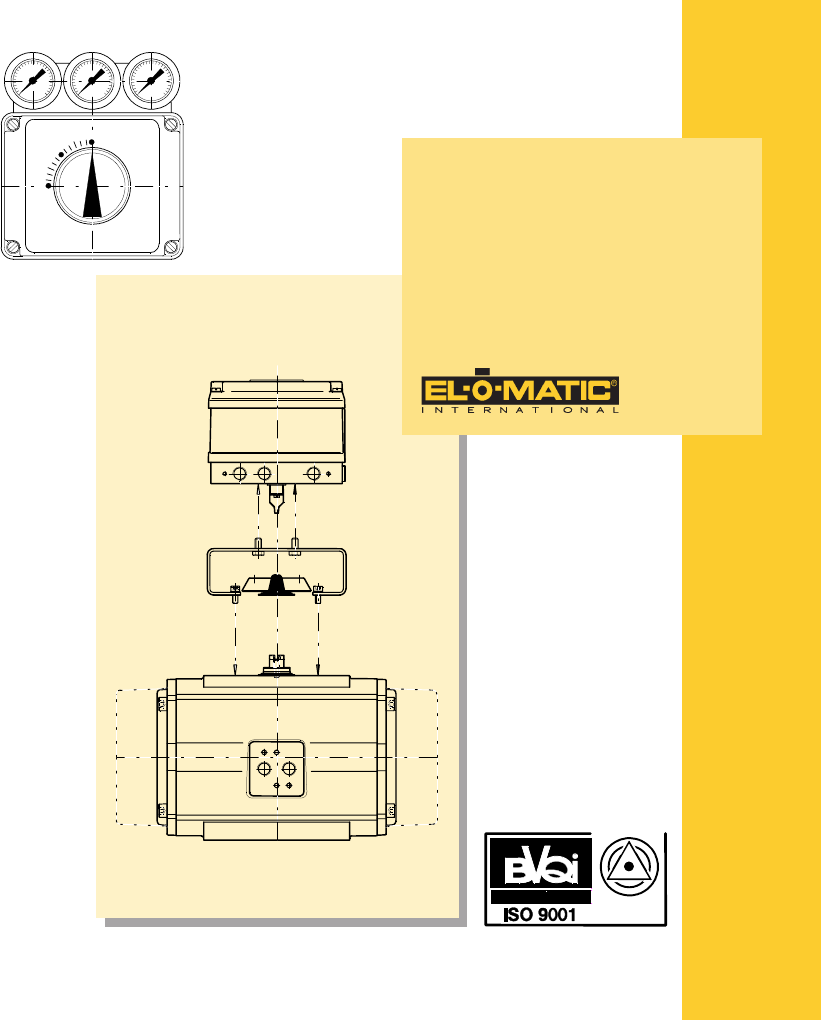
Installation and Operation
Manual
Electro-Pneumatic Positioner F20
Accredited by the
Dutch Council for
Certification
English
Deutsch
Nederlands

2DOC,F20,EDN Rev.: -
Contents (English)
1.0 Introduction .................................................................. 4
1.1 Product Description F20 ....................................... 4
1.2 Operating Principles .............................................. 6
2.0 Installation - Rotary Actuators ................................... 8
2.1 Mechanical Installation - Rotary Actuators ............. 8
2.2 Pneumatic Connections ....................................... 10
2.2.1 Double acting ....................................................... 10
2.2.2 Single acting ........................................................ 10
3.0 Installation - Linear Actuators .................................. 12
3.1 Mechanical Installation - Linear Actuators ........... 12
3.1.1 Installation sequence ........................................... 12
3.2 Pneumatic Connections ....................................... 14
3.2.1 Double acting ....................................................... 14
3.2.2 Single acting ........................................................ 14
4.0 Electrical Connections - Initial Setup ....................... 16
4.1 Electrical Connections ......................................... 16
4.2 Initial Setup - Zero, Range and Sensitivity ........... 16
4.3 Zero Setting ......................................................... 16
4.4 Range Setting ...................................................... 16
4.5 Sensitivity Setting................................................. 16
4.6 Split range setting ................................................ 18
5.0 Failure Modes............................................................. 20
5.1 Failure Modes - Double acting ............................. 20
5.1.1 Changes for Reverse Acting ................................ 20
5.2 Failure Modes - Single Acting (Spring return) ...... 22
5.2.1 Changes for Reverse Acting ................................ 22
6.0 General specifications .............................................. 24
6.1 Certificates .......................................................... 25
7.0 PTF20 option .............................................................. 26
7.1 Introduction .......................................................... 26
7.2 Installation ............................................................ 26
Inhalt (Deutsch)
1.0 Einführung ............................................................................. 5
1.1 Produktbeschreibung F20 .............................................. 5
1.2 Arbeitsweise ................................................................... 7
2.0 Einbau Drehantriebe ............................................................. 9
2.1 Mechanischer Einbau - Drehantriebe ........................... 9
2.2 Pneumatikanschlüsse ................................................... 11
2.2.1 Doppeltwirkende Ausführung ..................................... 11
2.2.2 Einfachwirkend Ausführung ........................................ 11
3.0 Einbau - Hubantriebe ......................................................... 13
3.1 Mechanischer Einbau - Hubantriebe ........................... 13
3.1.1 Montageablauf ............................................................. 13
3.2 Pneumatikanschlüsse ................................................... 15
3.2.1 Doppeltwirkende Ausführung ..................................... 15
3.2.2 Einfachwirkende Ausführung ...................................... 15
4.0 Elektrische Anschlüsse - Anfangseinstellungen ................ 17
4.1 Elektrische Anschlüsse ................................................. 17
4.2 Anfangseinstellungen - Null, Bereich und Totzone ..... 17
4.3 Nullpunkteinstellung .................................................... 17
4.4 Bereicheinstellung ........................................................ 17
4.5 Einstellung der Empfindlichkeit .................................. 17
4.6 Einstellung für geteilten Eingangsbereich / Split range 19
5.0 Ausfallarten ......................................................................... 21
5.1 Ausfallarten Doppeltwirkend ....................................... 21
5.1.1 Umschaltung auf umgekehrte Wirkung ....................... 21
5.2 Ausfallarten - Einfachwirkend (Federrückführung) .... 23
5.2.1 Umschaltung auf umgekehrte Wirkung ....................... 23
6.0 Allgemeine technische Daten .............................................. 24
6.1 Zertificate ..................................................................... 25
7.0 Optionsbaugruppe PTF20 .................................................. 27
7.1 Einführung ................................................................... 27
7.2 Einbau .......................................................................... 27
Inhoud (Nederlands)
1.0 Introductie .................................................................... 5
1.1 Produktomschrijving F20 ....................................... 5
1.2 Werkingsprincipes ................................................. 7
2.0 Montage op roterende aandrijvingen ......................... 9
2.1 Montage op roterende aandrijvingen ..................... 9
2.2 Pneumatische aansluitingen ................................ 11
2.2.1 Dubbelwerkende uitvoering ................................. 11
2.2.2 Enkelwerkende uitvoering .................................... 11
3.0 Montage - lineaire aandrijvingen .............................. 13
3.1 Montage - lineaire aandrijvingen .......................... 13
3.1.1 Montagevolgorde ................................................. 13
3.2 Pneumatische aansluitingen ................................ 15
3.2.1 Dubbelwerkende uitvoering ................................. 15
3.2.2 Enkelwerkende uitvoering .................................... 15
4.0 Elektrische aansluitingen - Initiële instelling .......... 17
4.1 Elektrische aansluitingen ..................................... 17
4.2 Initiële instelling - nulpunt, bereik en gevoeligheid 17
4.3 Nulpunt instellen .................................................. 17
4.4 Instellen van het bereik ........................................ 17
4.5 Instellen van de gevoeligheid ............................... 17
4.6 Instellen voor gesplitst bereik ............................... 19
5.0 Storingen .................................................................... 21
5.1 Storingen - dubbelwerkend .................................. 21
5.1.1 Wijzigingen voor omgekeerde werking ................ 21
5.2 Storingen- enkelwerkend (veerretour) ................. 23
5.2.1 Wijzigingen voor omgekeerde werking ................ 23
6.0 Algemene specificaties ............................................. 24
6.1 Certifikaten .......................................................... 25
7.0 Optie PTF20 ................................................................ 27
7.1 Inleiding ............................................................... 27
7.2 Installatie .............................................................. 27

3DOC,F20,EDN Rev.: -
WARNUNG
Das Gerät darf nur von Fachpersonal, das mit der Montage, der Inbetriebnahme und dem Betrieb dieses Produktes vertraut ist, montiert und in Betrieb genommen werden.
Fachpersonal im Sinne dieser Einbau- und Bedienungsanleitung sind Personen, die auf Grund ihrer fachlichen Ausbildung, ihrer Kenntnisse und Erfahrungen sowie ihrer
Kenntnisse der einschlägigen Normen die ihnen übertragenen Arbeiten beurteilen und mögliche Gefahren erkennen können.
Bei Geräten in explosionsgeschützter Ausführung müssen die Personen eine Ausbildung oder Unterweisung bzw. eine Berechtigung zum Arbeiten an explosions-
geschützten Geräten in explosionsgefährdeten Anlagen haben.
Gefährdungen, die am Stellventil vom Durchflußmedium, dem Stelldruck und von beweglichen Teilen ausgehen können, sind durch geeignete Maßnahmen zu verhin-
dern. Sachgemäßer Transport und fachgerechte Lagerung des Gerätes werden vorausgesetzt.
Die elektrische Sicherheit wird allein durch die speisenden Geräte bestimmt, da im Gerät nur Kleinspannungen zur Anwendung kommen. Bei der elektrischen Installation
sind die geltenden Vorschriften zu beachten. Zusätzlich sind bei der Installation von explosionsgefährdeten Geräten die Angaben der Konformitätsbescheinigung und die
Vorschriften für die Errichtung explosionsgefährdeter Anlagen zu beachten.
Waarschuwing
Dit apparaat mag alleen door vakpersoneel, welke met de montage, het in bedrijf stellen en het in bedrijf zijn, bekent zijn, gemonteerd en in bedrijf geno-
men worden.
Vakpersoneel zoals in deze montage handleiding bedoelt, zijn personen, die op grond van hun vaktechnische opleiding, hun kennis en ervaring als ook
hun kennis van de desbetreffende normen de hun opgedragen arbeid kunnen beoordelen en de mogelijke gevaren kunnen herkennen.
Bij apparaten in explosieveilige uitvoeringen moeten die personen een opleiding of onderricht in resp. een bevoegdheid voor het werken met explosie-
veilige apparaten in omgevingen met dreigend explosie gevaar, hebben.
Gevaar, welke aan de regelklep van het doorstroommedium, de werkdruk, en de bewegende delen uitgaan, moeten door geëigende maatregelen verhin-
derd worden. Deskundig transport en vakkundige opslag van het apparaat wordt verondersteld.
De elektrische zekerheid wordt alleen bepaald door de voedende apparaten, omdat in het apparaat alleen laagspanning gebruikt worden. Bij de elektri-
sche installatie moeten alle geldende voorschriften in acht genomen worden. Aanvullend moeten bij de installatie van apparaten met dreigend explosie
gevaar de aanwijzing van de konformiteitsgetuigschrift en de voorschriften voor het vestigen van een installatie met dreigend explosie gevaar in acht ge-
nomen worden.
Warning
The device may only be operated by craftsmen who are familiar with the mounting, the installation and operation of this product.
Craftsmen as mentioned in this installation and operation manual are persons who, on the basis of their crafts education, their knowledge and experience
as well their knowledge of the applicable standards can judge the to them commissioned labour and can recognise the possible dangers.
To work on the device in an explosion proof execution, the craftsmen must have an education or instruction respectively the legitimacy to work on
explosion proof devices in explosion hazardous areas.
Dangers due to the control valve of the flow media, the working pressure and the moving parts have to be avoided by appropriate measures. Professional
transport and storage of the device is required.
The electrical security will be determined by power supply, because in the device only low voltageis applied. The electrical installation has to comply with
the applicable standards. Additionally for the installation of explosion hazardous devices the notifications of the certificate of conformity and the
regulations for to establish explosion hazardous installations have to be observed.
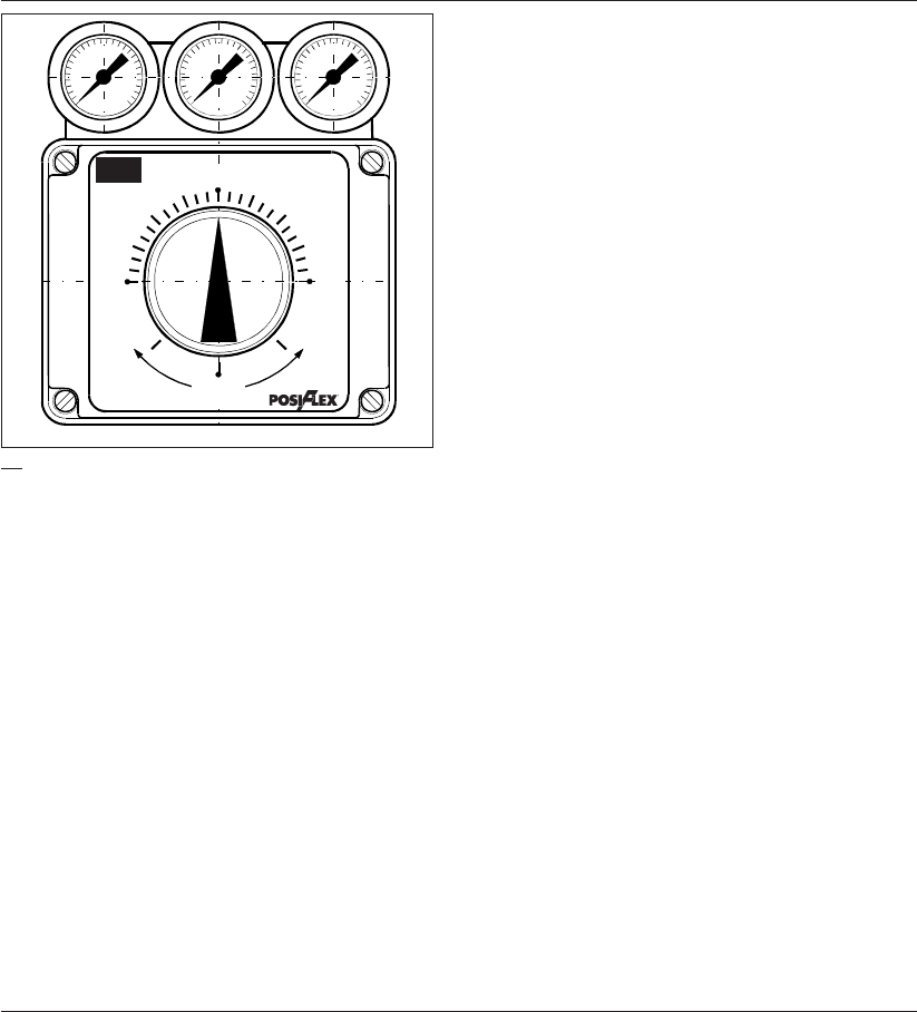
4DOC,F20,EDN Rev.: -
1.0 Introduction / Einführung / Introductie
1.0
1.1 Product Description F20
El-o-matic POSIFLEX positioners belong to the most advanced
positioners of their type on the market today. This latest version
is made possible by a combination of the newest electronics
developments with a high precision spool type pneumatic pilot
for the volume amplifier.
The F20 is a true 2 wire instrument: An industry standard 4 to
20 mA. signal provides both the controlling signal and the
power supply for the electronics. As such the positioner is plug
compatible with the current industry standard.
The use of electronics as the controlling element means that all
the usual control characteristics: Zero, range and sensitivity
are all electronically resettable using trimmers on the control
card.
Both rotary and linear applications are catered for, the differ-
ence being with feedback mechanism and the mounting
methods. A single universal positioner is suitable for both
double acting and single acting (spring return) actuators. The
standard internal feedback provides a linear relationship
between the input signal and the output movement.
The functionallity of the F20 positioner can be extended by a
"Plug-in" PTF20 Option for a analog 4-20mA feedback signal.
This option is, well protected, mounted inside the F20 enclo-
sure and has its own feedback potentiometer.
ELECTRO-PNEUMATIC
POSITIONER
F20 Rotary
Linear
Closed
Open Open
Closed

5DOC,F20,EDN Rev.: -
1.0 Introduction / Einführung / Introductie
1.1 Produktbeschreibung F20
Die El-o-Matic POSIFLEX-Positioner gehören zu den fortschritt-
lichsten Stellungsreglern ihrer Art am Markt. Die letzte Ausführung
wurde möglich durch die Kombination der neuesten Elektronik-Ent-
wicklungen mit einem Präzisions-Stahlschieberventil zur pneumati-
schen Ausgangsverstärkung.
Der F20 ist ein reines 2-Leitergerät, dessen 4-20 mA Eingangssignal
sowohl als Regelsignal als auch zur Energieversorgung der
Elektronikbaugruppe dient. Damit ist dieser Positioner kompatibel
zum aktuellen Industriestandard. Die Nutzung der Elektronik zur In-
formationsverarbeitung gestattet die Einstellung der üblichen Para-
meter Nullpunkt, Bereich und Verstärkung mittels Trimm-Potentio-
meter auf der Leiterplatte. Es sind Ausführungen sowohl für Dreh-
antriebe als auch für Linearantriebe verfügbar, die sich nur im Rück-
führmechanismus und in der Montageweise unterscheiden.
Der Positioner ist ein Universalgerät sowohl für doppeltwirkende als
auch für einfachwirkende (mit Federrückstellung) Stellantriebe. Die
Standardrückführung stellt eine lineare Beziehung zwischen dem
Eingangssignal und der Ausgangsbewegung her.
Die Funktion des Stellungsregler F20 kann auf Wunsch erweitert
werden mit einer aufsteckbaren Baugruppe PTF20 zur analogen
Stellungsrückmeldung mit dem 4-20 mA-Signal. Diese Baugruppe
ist, gut geschützt, im gleichen Gehäuse untergebracht und verfügt
über ein separates Meßpotentiometer zur Rückführung.
1.1 Produktomschrijving F20
El-o-matic klepstandstellers van het type POSIFLEX behoren
tot meest geavanceerde klepstandstellers in hun soort die
thans op de markt verkrijgbaar zijn. Deze nieuwste versie is
gebaseerd op een koppeling van de meest recente ontwikkelin-
gen op het gebied van de elektronica met een uiterst nauwkeu-
rig werkende pneumatische stuurklep van het plunjertype voor
de volumeversterker.
De F20 is een 2-draads instrument: een 4 tot 20 mA signaal
volgens industrienorm levert niet alleen het stuursignaal maar
zorgt ook voor de stroomvoorziening van de elektronische ap-
paratuur. Als zodanig is de klepstandsteller “plug-compatible”
conform de huidige industrienorm.
Door het gebruik van elektronische stuurelementen kunnen
alle gebruikelijke stuurkarakteristieken, zoals nulinstelling,
werkbereik en gevoeligheid, door middel van trimmers op de
besturingskaart elektronisch gereset worden.
Zowel roterende als lineaire toepassingen zijn mogelijk; ze ver-
eisen alleen een ander terugvoermechanisme en een andere
montagewijze. Een enkelwerkende universele klepstandsteller
is geschikt voor zowel dubbel- als enkelwerkende (veer-
belaste) aandrijvingen. De interne terugkoppeling die stan-
daard wordt geleverd, legt een lineair verband tussen het
ingangssignaal en de uitgaande beweging.
De functionaliteit van de F20 klepstandsteller kan uitgebreid
worden met een PTF20 "Plug-in" optie voor een 4-20 mA
terugmeldsignaal. Deze optie wordt, goed beschermd, in de
F20 behuizing gemonteerd en heeft een eigen
terugmeldpotentiometer.
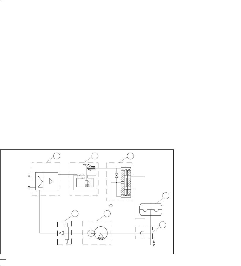
6DOC,F20,EDN Rev.: -
1.2 Operating Principles
The positioner provides the means for a pneumatic actuator to
be accurately positioned to any point between full open and full
closed position. The actuator’s movement is controlled in
proportion to a 4-20 mA incoming signal.
The actuator’s movement is monitored by the integral feedback
potentiometer (7), the signal from this and the incoming signal
are fed to the comparative electronics on the main circuit board
(1).
Providing these two signals are equal the resulting signal sent
to the I/P converter (2) is “Neutral” and the spool of the pilot
valve (3) is held in the mid or blocked position.
In this state the actuator remains locked in the last set position,
that is at it’s “Set point”.
If, either the input mA. signal or the valve position changes then
the difference is sensed and the signal to the I/P is either
increased or decreased. This causes a corresponding move-
ment of the pilot spool (3) which in turn starts the actuator’s
movement (4) towards the new “Set point”. On reaching this the
two signals are again equal and movement stops at this new
“Set point”.
For single acting (spring return) actuators only a single air line
is used, the other port at the spool valve (3) is plugged off.
1.0 Introduction / Einführung / Introductie
123
4
5
67
4-20 mA
Signal input
4-20 mA Signal input =
4-20 mA Eingangssignal =
4-20 mA Stuursignaal
1.1

7DOC,F20,EDN Rev.: -
1.0 Introduction / Einführung / Introductie
1.2 Arbeitsweise
Der Stellungsregler bietet die Möglichkeit, ein pneumatisches Stell-
glied in jeder beliebigen Stellung zwischen völlig auf und völlig ge-
schlossen zu positionieren. Die Bewegung des Stellgliedes wird pro-
portional zu einem Eingangssignal von 4-20 mA geregelt.
Die Stellbewegung des Antriebes wird von einem Rückführ-
potentiometer (7) erfaßt und in der Elektronikbaugruppe (1) mit
dem Eingangssignal verglichen.
Liegt Soll-Istwert Gleichheit vor, verbleibt der Stellantrieb in der je-
weiligen Position.
Ändert sich das Stellsignal oder die Antriebsposition, wird die Ab-
weichung erfaßt. Die Soll-Istwert Differenz wird elektronisch ver-
stärkt und ändert das Magnetfeld der Festspule (2). Damit ändert
sich der Abstand zwischen Düse und Prallplatte. Die Kaskaden-
druckänderung verstellt das Verstärker-Ventil (3) am Ausgang. Der
Antrieb (4) bewegt sich in Richtung neuer Sollwert und stoppt bei
Erreichen der neuen Sollposition.
Bei einfachwirkenden Antrieben wird nur der eine Ausgang genutzt.
Der andere Ausgang wird verschlossen.
1.2 Werkingsprincipes
Door de montage van klepstandsteller F20 kan een pneumati-
sche aandrijving nauwkeurig in elke stand tussen volledig geo-
pend en volledig gesloten worden gezet. De beweging van de
aandrijving wordt evenredig aan een 4-20 mA ingangssignaal
geregeld.
De beweging van de aandrijving wordt bewaakt door de inte-
grale terugkoppelpotentiometer (7). Het door deze
potentiometer afgegeven signaal en het ingangssignaal worden
aan de vergelijkingselektronica op de hoofdprintplaat (1) toe-
gevoerd.
Alleen wanneer deze twee signalen gelijk zijn, zal het aan de I/
P-omzetter (2) afgegeven resulterende signaal “neutraal” zijn,
waarbij de plunjer van de stuurklep (3) in de centrale of geblok-
keerde stand wordt gehouden.
In deze stand blijft de aandrijving in de laatst ingestelde positie,
te weten het instelpunt, vergrendeld.
Indien het mA-ingangssignaal of de klepstand verandert, wordt
het verschil gedetecteerd, waardoor het signaal naar de I/P
verhoogd dan wel verlaagd wordt. Dit resulteert in een corres-
ponderende beweging van de stuurklepplunjer (3) die wederom
de beweging van de aandrijving (4) naar het nieuwe instelpunt
in gang zet. Zodra dit punt is bereikt, zijn de beide signalen
weer gelijk en komt de beweging bij dit nieuwe instelpunt tot
stilstand.
Bij enkelwerkende (veerbelaste) aandrijvingen wordt slechts
een enkele luchtleiding gebruikt; de andere poort bij de
plunjerklep (3) wordt afgestopt.
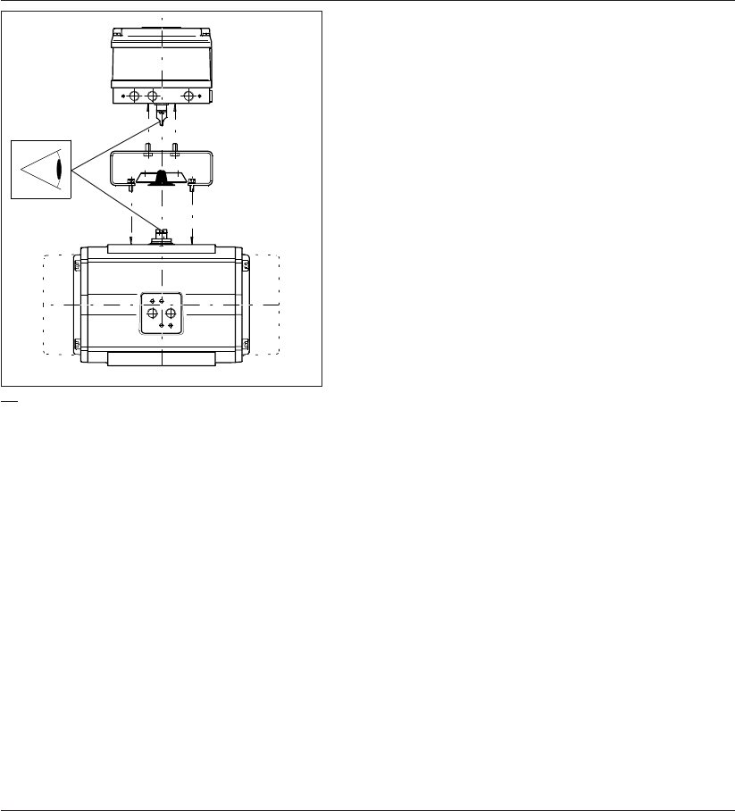
8DOC,F20,EDN Rev.: -
2.1 Mechanical Installation - Rotary
Actuators
The positioner is mounted on to the top surface of the pneu-
matic actuator using an appropriate mounting kit.
The positioner’s mounting configuration is to the VDE/VDI 3845
standard, if the actuator is to the same standard, a standard
NAMUR mounting kit can be used, otherwise a special
mounting kit will have to be obtained.
Assuming the installation will use the standard NAMUR
mounting kit, proceed as follows:
1. Fix the bracket to the top surface of the actuator using the 4
screws provided.
2. Locate the positioner in place on top of the bracket, making
sure that the 4 mm. tongue locates properly into it’s slot in
the actuator spindle.
3. Fix the positioner to the bracket using the 4 screws pro-
vided.
2.0
2.0 Installation - Rotary Actuators / Einbau Drehantriebe / Montage op roterende
aandrijvingen

9DOC,F20,EDN Rev.: -
2.0 Installation - Rotary Actuators / Einbau Drehantriebe / Montage op roterende
aandrijvingen
2.1 Mechanischer Einbau - Drehantriebe
Der Stellungsregler wird oben auf dem pneumatischen Stellglied
montiert unter Anwendung eines entsprechenden Montagesatzes.
Die Montagekonfiguration des Stellungsreglers entspricht der Norm
VDE/VDI 3845. Wenn das Stellglied der gleichen Norm entspricht,
kann ein Standard- NAMUR -Montagesatz verwendet werden. Sonst
sollte ein Sondermontagesatz bestellt werden.
Wenn der Standard-NAMUR-Montagesatz zum Einbau verwendet
wird, ist wie folgt vorzugehen:
1. Die Halterung mit den 4 mitgelieferten Schrauben auf der Ober-
seite des Stellglieds befestigen.
2. Den Stellungsregler oben auf die Halterung anordnen und kon-
trollieren, daß die federnde Kupplung richtig in die entsprechen-
de Aussparung in der Spindel des Stellglieds eingreift.
3. Den Stellungsregler mit den 4 mitgelieferten Schrauben an der
Halterung befestigen.
2.1 Montage op roterende aandrijvingen
De klepstandsteller wordt met behulp van een daarvoor ge-
schikte montagekit bovenop de pneumatische aandrijving ge-
monteerd.
De wijze van montage van de klepstandsteller is conform de
norm VDE/VDI 3845. Indien de aandrijving aan dezelfde norm
voldoet, kan een standaard NAMUR-montagekit worden ge-
bruikt. Als dit niet het geval is, dient u een speciale montagekit
te bestellen.
Ervan uitgaande dat bij de montage gebruik wordt gemaakt
van de standaard NAMUR-montagekit, dient als volgt te werk
worden gegaan:
1. Bevestig de beugel met de 4 meegeleverde schroeven bo-
venop de aandrijving.
2. Plaats de klepstandsteller bovenop de beugel en zorg er-
voor dat de 4 mm lange lip goed in de corresponderende
groef in de spil van de aandrijving valt en dat de
centreerschroef in de juiste stand staat.
3. Monteer de klepstandsteller met de 4 meegeleverde schroe-
ven op de beugel.
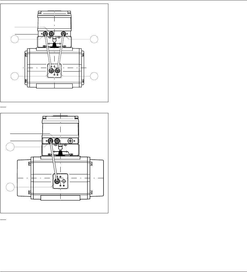
10 DOC,F20,EDN Rev.: -
2.2 Pneumatic Connections
Assuming a standard (direct acting) installation with an
increasing signal to open the valve in a CCW (counter clock-
wise) direction.
Before connecting any air supply make sure that the air
available is clean dry instrument air filtered to at least 25
microns.
2.2.1 Double acting
1. Connect an appropriate piece of air tubing between the port
1. on the positioner to the “A” port on the actuator. (The “A”
port is the one that when air is applied to it, rotates the
actuator in a counter clockwise direction).
2. Connect an appropriate piece of air tubing between the port
2. on the positioner to the “B” port on the actuator. (The “B”
port is the one that when air is applied to it, rotates the
actuator in a clockwise direction).
3. If the positioner is required to meet enclosure rating IP54, be
sure that the sintered filter is in place at the “Exhaust” port.
4. Connect an air supply to the positioner port marked
“Supply”.
Note:
The same procedure is applicable to connect a double
acting actuator with reverse action. Only select "Reverse
Action", see page 20.
For electrical installation, see page 16.
2.2.2 Single acting
1. Connect an appropriate piece of air tubing between the port
1. on the positioner to the “A” port on the actuator. (The “A”
port is the one that, when air is applied to it, rotates the
actuator in a counter clockwise direction).
2. Connect an air supply to the positioner port marked
“Supply”.
3. If the positioner is required to meet enclosure rating IP54, be
sure that the sintered filter is in place at the “Exhaust” port.
Note:
The same procedure is applicable to connect a single
acting actuator with reverse action, only select "Reverse
Action", see page 22.
For electrical installation, see page 16.
2.0 Installation - Rotary Actuators / Einbau Drehantriebe / Montage op roterende
aandrijvingen
Double acting
Supply
Exhaust
Supply
Exhaust
12
AB
Double acting
2.1
2.2
Supply
Exhaust
1
A
= Doppelt Wirkend
= Luftversorgung
= Entlüftung
= Dubbel werkend
= Luchtaansluiting
= Ontluchting
Single acting

11DOC,F20,EDN Rev.: -
2.0 Installation - Rotary Actuators / Einbau Drehantriebe / Montage op roterende
aandrijvingen
2.2 Pneumatikanschlüsse
Es wird ausgegangen von einer (direkt wirkenden) Standardaus-
führung mit ansteigendem Signal zum Öffnen des Ventils im Gegen-
uhrzeigersinn.
Bevor die Luftversorgung angeschlossen wird, ist sicherzustellen,
daß die verfügbare Luft reine trockene Instrumentenluft ist, die
mit einer Feinheit von 25 Mikrometer gefiltert ist.
2.2.1 Doppeltwirkende Ausführung
1. Einen geeigneten Luftschlauch zwischen Anschluß 1 am
Stellungsregler und Anschluß "A" am Stellglied anbringen. (An-
schluß "A" ist der Anschluß, der bei Beaufschlagung mit Luft
eine Drehbewegung des Stellglieds im Gegenuhrzeigersinn be-
wirkt).
2. Einen geeigneten Luftschlauch zwischen Anschluß 2 am
Stellungsregler und Anschluß "B" am Stellglied anbringen. (An-
schluß "B" ist der Anschluß, der bei Beaufschlagung mit Luft
eine Drehbewegung des Stellglieds im Uhrzeigersinn bewirkt).
3. Die Luftversorgung an den Anschluß "SUPPLY" (Zuluft) des
Stellungsreglers anschließen.
4. An den Anschluß "Exhaust" (Entlüftung) sind Elemente anzu-
schließen, die IP54 gewährleisten (z.B. mitgelieferter Schall-
dämpfer).
Bemerkung:
Für einen doppeltwirkenden Antrieb mit Wirkung in umgekehr-
ter Richtung ist dem selben Verfahren zu folgen, mit dem Unter-
schied, daß die Einstellung "Umgekehrte Wirkungsrichtung" zu
wählen ist. Siehe Seite 21.
Elektrische Anschlüsse, siehe Seite 17.
2.2.2 Einfachwirkend
1. Einen geeigneten Luftschlauch zwischen Anschluß 1 am
Stellungsregler und Anschluß "A" am Stellglied anbringen. (An-
schluß "A" ist der Anschluß, der bei Beaufschlagung mit Luft
eine Drehbewegung des Stellglieds im Gegenuhrzeigersinn be-
wirkt).
2. Die Luftversorgungsquelle an den Anschluß "SUPPLY" (Zuluft)
des Stellungsreglers anschließen.
3. An den Anschluß "Exhaust" (Entlüftung) sind Elemente anzu-
schließen, die IP54 gewährleisten (z.B. mitgelieferter Schall-
dämpfer).
Bemerkung:
Für einen einfachwirkenden Antrieb mit Wirkung in umgekehr-
ter Richtung ist dem selben Verfahren zu folgen, mit dem Unter-
schied, daß die Einstellung "Umgekehrte Wirkungsrichtung" zu
wählen ist. Siehe Seite 23.
Elektrische Anschlüsse, siehe Seite 17.
2.2 Pneumatische aansluitingen
Hierbij wordt uitgegaan van een standaard montage (voor di-
recte werking), waarbij een in intensiteit toenemend signaal de
afsluiter linksom moet openen.
Alvorens lucht aan te sluiten, dient u te controleren of hier
sprake is van schone, droge instrumenten-lucht die mini-
maal tot op 25 micron is gefilterd.
2.2.1 Dubbelwerkende uitvoering
1. Breng een passend stuk luchtleiding tussen poort 1 op de
klepstandsteller en poort “A” op de aandrijving aan. (Met
poort “A” wordt die poort bedoeld, waarbij de aandrijving
linksom draait wanneer lucht op deze poort wordt gezet.)
2. Breng een passend stuk luchtleiding tussen poort 2 op de
klepstandsteller en poort “B” op de aandrijving aan. (Met
poort “B” wordt die poort bedoeld, waarbij de aandrijving
rechtsom draait wanneer lucht op deze poort wordt gezet.)
3. Sluit de instrumentenlucht aan op de met “Supply” aange-
duide poort.
4. Indien de klepstandsteller aan beschermingsklasse IP54
moet voldoen, dient b.v. de meegeleverde geluidsdemper in
de met “Exhaust” aangeduide poort te zijn aangebracht.
Opmerking:
De zelfde produre is van toepassing voor het aansluiten
van dubbelwerkende aandrijvingen met omgekeerde wer-
king. Echter, selecteer "Omgekeerde Werking" zie pagina
21.
Elektrische aansluitingen, zie pagina 17.
2.2.2 Enkelwerkende uitvoering
1. Breng een passend stuk luchtleiding tussen poort 1 op de
klepstandsteller en poort “A” op de aandrijving aan. (Met
poort “A” wordt die poort bedoeld, waarbij de aandrijving
linksom draait wanneer lucht op deze poort wordt gezet.)
2. Sluit lucht aan op de met “Supply” aangeduide poort van de
klepstandsteller.
3. Indien de klepstandsteller aan beschermingsklasse IP54
moet voldoen, dient b.v. de meegeleverde geluidsdemper in
de met “Exhaust” aangeduide poort te zijn aangebracht.
Opmerking:
De zelfde produre is van toepassing voor het aansluiten
van enkelwerkende aandrijvingen met omgekeerde wer-
king. Echter, selecteer "Omgekeerde Werking" zie pagina
23.
Elektrische aansluitingen, zie pagina 17.
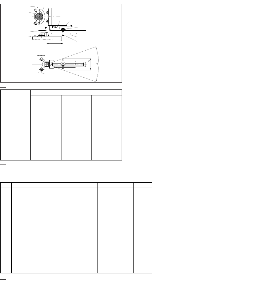
12 DOC,F20,EDN Rev.: -
3.1 Mechanical Installation - Linear Ac-
tuators
The mounting set is used for mounting POSIFLEX positioners
on linear actuator which have mountings in accordance with
DIN IEC 534-6. All parts are made from stainless steel. The
mounting sets contain two different levers for different stroke
ranges:
1. Stroke 10 - 65 mm
2. Stroke 65 - 100 mm
Mounting is possible for actuators with pillars, by using the
bracket (7) with the U-bolt (8). Or for actuators with a cast pad,
by direct fitting using the screw M8x20 (16) with washer M8
(17). The linear moving of actuator has to be converted into a
rotation of the shaft of positioner. The distance ”A” between
coupling bolt (6) and shaft of positioner is set with reference to
the table below. This distance is a function of stroke S. Pre-
setting the linkage with this distance ”A” enables the best range
setting to be achieved with only a small adjustment on the
positioners’ range setting. A spring (3); (5) in lever (2); (4)
eliminates play in the linkage.
3.0 Installation - Linear Actuators / Einbau - Hubantriebe / Montage - lineaire aandrijvingen
9;11
7
8
15
12;18
A6
12;14
10;13
2;3 / 4;5
1
30
3.1
3.2
l = long lever (4)
k = short lever (2)
reference to the table 3.2.
5. Fix coupling bolt with nut M6 (10).
6. Adjust positioner (zero, range, amplification).
7. Change setting of zero and range as required.
Note:
1. POSIFLEX positioners for linear applications are
adjusted for an angle of 40° as standard (see table
above). For different strokes i.e. 10mm or 100 mm
(other angle!) reset zero and range adjustment of
F20.
2. Several parts, standard parts e.g., of mounting kit
are already pre-assembled for ease of assembly.
3. Using only one lever is possible in applications of
F20 if the relation of stroke and distance ”A” is not
more than 1,0. To use this type of assembly,
please also order coupling bolt ES (Part number
6.003618).
l = langer Hebel (4)
k = kurzer Hebel (2)
l = lange hefboom (4)
k = korte hefboom (2)
3.3
No. Qty Description Umschreibung
Omschrijving
Norm
1 1 Carrier bracket Mitnehmerblech
Meeneembeugel
2 1 Lever, short Heb el-ku rz
Hefboom kort
3 1 Spring, short Feder-kurz
Veer kort
4 1 Lever, long Heb el-lan g
Hefboom lang
51Spring,long Feder-lang
Hefboom kort
6 1 Coupling bolt Mitn ehmer
Meeneembout
7 1 Bracket for postioner Montagewinkel
Montagebeugel
82U-bolt Spannbügel
Spanbeugel
94NutM8 Mutter M8
Moer M8
DIN 934
10 1 Nut M6 Mu tter M6
Moer M6
DIN 439
11 4 Lockwasher B8 Federring B8
Ring B8
DIN 127
12 3 Lockwasher B6 Federring B6
Ring B6
DIN 127
13 1 Disk A6,4 Scheibe A6,4
Schijf A6,4
DIN9021
14 3 Screw M6x10 Schraube M6x10
Schroef M6x10
DIN 933
15 1 Screw M3x10 Schraube M3x10
Schroef M3x10
DIN 912
16 1 Screw M8x20 Schraube M8x20
Schroef M8x20
DIN 933
17 1 Lockwasher B8 Federrin
g
B8
Rin
g
B8
DIN 917
18 2 Screw M6x12 Schraube M6x12
Schroef M6x12
DIN 933
S (in mm.) A (in mm.)
∝= 24,5° ∝= 40° ∝= 49°
10 23 (k)
16 22 (k)
20 27 (k)
30 41 (k)
32 44 (k)
50 68 (k)
55 75 (k)
65 89 (k), (l)
75 103 (l)
80 110 (l)
100 110 (l)
3.1.1 Installation sequence
The following installation sequence is for a positioner with a
direct action (increasing signal opens the valve with rising
spindle.)
1. Insert lever (2); (4) at end of positioner shaft and fix it with
screw.
2. Check the standard interface of actuator and mount bracket
(7) at left side of actuator - at pillar or casting pad.
3. Choose the position of bracket (7) where lever (2); (4) is in a
horizontal position and the actuator is in mid stroke.
4. Position the coupling bolt (6) for a correct distance ”A”, with

13DOC,F20,EDN Rev.: -
3.0 Installation - Linear Actuators / Einbau - Hubantriebe / Montage - lineaire aandrijvingen
3.1 Mechanischer Einbau - Hubantriebe
Zum Anbau ist der Montagewinkel (7) mit den Spannbügeln (8) für
Antriebe mit Säulenjoch oder Schraube M8x20 (16) mit Unterleg-
scheibe M8 (17) für Antriebe mit Gußjoch vorgesehen. Die
Montagesätze haben zwei verschiedene Hebel für verschiedene
Hubbereiche;
1. Hub 10 - 65 mm
2. Hub 65 - 100 mm
Zur funktionellen Kopplung muß die Linearbewegung des Antriebs
in eine Drehbewegung der Welle des Stellungsreglers gewandelt
werden. Hierzu dient das an der standardisierten Schnittstelle der
Antriebsspindel montierte Mitnehmerblech (1), das über den Mit-
nehmer (6) den Hebel (2); (4) dreht. Um mit optimalen
Übertragungsbedingungen und nur geringfügigen Korrekturen der
Stellungsregler-Kalibrierung arbeiten zu können, ist der Abstand
"A" des Mitnehmers von der Stellungsregler-Welle in Abhängigkeit
vom Antriebshub gemäß Tabelle (siehe unten) einzustellen. Zur Ver-
meidung von Übertragungsspiel ist im Hebel (2); (4) die Feder (3);
(5) eingelegt.
3.1 Montage - lineaire aandrijvingen
Voor aandrijvingen met een zuilenjuk worden een Montage-
beugel (7) en een Spanbeugel (8) meegeleverd. Voor aandrij-
vingen met gietwerkjuk worden schroef M8x20 (16) met sluit-
ring M8 (17) meegeleverd. De montageset hebben twee ver-
schillende hefbomen voor verschillende slagbereiken;
1. Slag 10 - 65 mm
2. Slag 65 - 100 mm
De lineaire beweging van de regelklep moet omgezet worden
in een draaibeweging van de as van de klepstandsteller. Hier-
voor dient het aan de gestandardiseerde interface van de
aandrijvingsspindel gemonteerde meeneembeugel (1), welke
via de meeneembout (6) hefboom (2;4) verdraait. Afstand "A"
dient volgens onderstaande abel ingesteld te worden. Dit zorgt
voor een optimale bereiksinstelling welke naderhand dan nog
gering bijgesteld dient te worden. De veer (3:5) zorgt voor een
spellingsvrije overbrenging
3.1.1 Montageablauf
Nachstehend folgt ein typisches Montagebeispiel für eine direkt wir-
kende Einheit (ansteigendes Signal öffnet ein Ventil mit steigender
Spindel).
1. Hebel (2); (4) auf Zweiflach am Wellenende des Stellungsreglers
aufstecken und anschrauben.
2. Montagewinkel (7) an linke Seite des Antriebsjochs (bei Sicht auf
Schnittstelle an Spindel) montieren
3. Im Säulenjoch den Montagewinkel in der Höhe so einstellen, daß
Hebel bei Hubmitte horizontal steht
4. Mitnehmer-Abstand A in Abhängigkeit vom Hub aus der Tabelle
entnehmen.
5. Mitnehmer auf Maß A einstellen und mit Mutter M6 (10) fest ar-
retieren.
6. Inbetriebnahme des Stellungsreglers
7. Bei Bedarf Nullpunkt und Bereichseinstellung korrigieren
Hinweise
1. Die POSIFLEX-Geräte für Hubantriebe sind auf den Schwenk-
winkel α=40° (siehe Tabelle) standardmäßig justiert. Für die An-
passung auf den kleineren oder größeren Schwenkwinkel für
Hub 10mm bzw. 100mm ist bei dem elektropneumatischen Stel-
lungsregler F20 die Einstellung für Nullpunkt und Bereich zu än-
dern.
2. Zur Erleichterung der Handhabung sind einzelne Baugruppen mit
Normteilen vorkomplettiert.
3. Eine Einstiftbetätigung des Schwenkhebels (ohne Mitnehmer-
blech 1) ist für den Stellungsregler F20 möglich, wenn das Ver-
hältnis von Hub und Maß A maximal 1,0 ist. Hierfür als Option
Mitnehmer ES (Typ-Nr. 6.003618) bestellen.
3.1.1 Montagevolgorde
Hieronder volgd een typische montagevolgorde voor een direct
werkende samenstelling (Bij stijgend signaal opend de afsluiter
met steigende spindel).
1. Hefboom (2);(4) op asuiteinde van de klepstandsteller mon-
teren
2. Montagebeugel (7) aan de linker kant van het aandrijvings-
juk (met zicht op de inteface aan de spindel) monteren.
3. De montagebeugel zodanig in de hoogte verschuiven, dat
hefboom horizontaal staat. De aandrijving moet hierbij in de
midden positie staan.
4. Afstand “A” volgens onderstaande tabel instellen.
5. Meeneembout vastzetten met moer M6 (10).
6. Afstellen klepstandsteller - Zie “Montage en bediening”.
7. Eventueel nulpunt, bereik en gevoeligheid corrigeren.
Opmerking
1. POSIFLEX-klepstandsteller voor lineaire aandrijvingen zijn
standaard ingesteld voor een hoekverdraaiing van
α
=40°
(zie tabel). Bij grotere of kleinere hoekverdraaiingen (bij een
slag van 10mm resp. 100mm) moet bij de elektro-pneumati-
sche klepstandsteller F20 de instelling voor nulpunt en be-
reik veranderd worden.
2. Voorgemonteerde montagesets zijn beschikbaar voor de
verschillende slagbereiken.
3. Een Eenstiftbediening van de hefboom (zonder meeneem-
beugel 1) is voor de klepstandsteller F20 mogelijk, wanneer
de verhouding van slag en maat “A” maximaal 1,0 is. Hier-
voor is als optie meenemer ES Eénstiftbediening voor F20
(Typ-Nr. 6.003618) te bestellen.
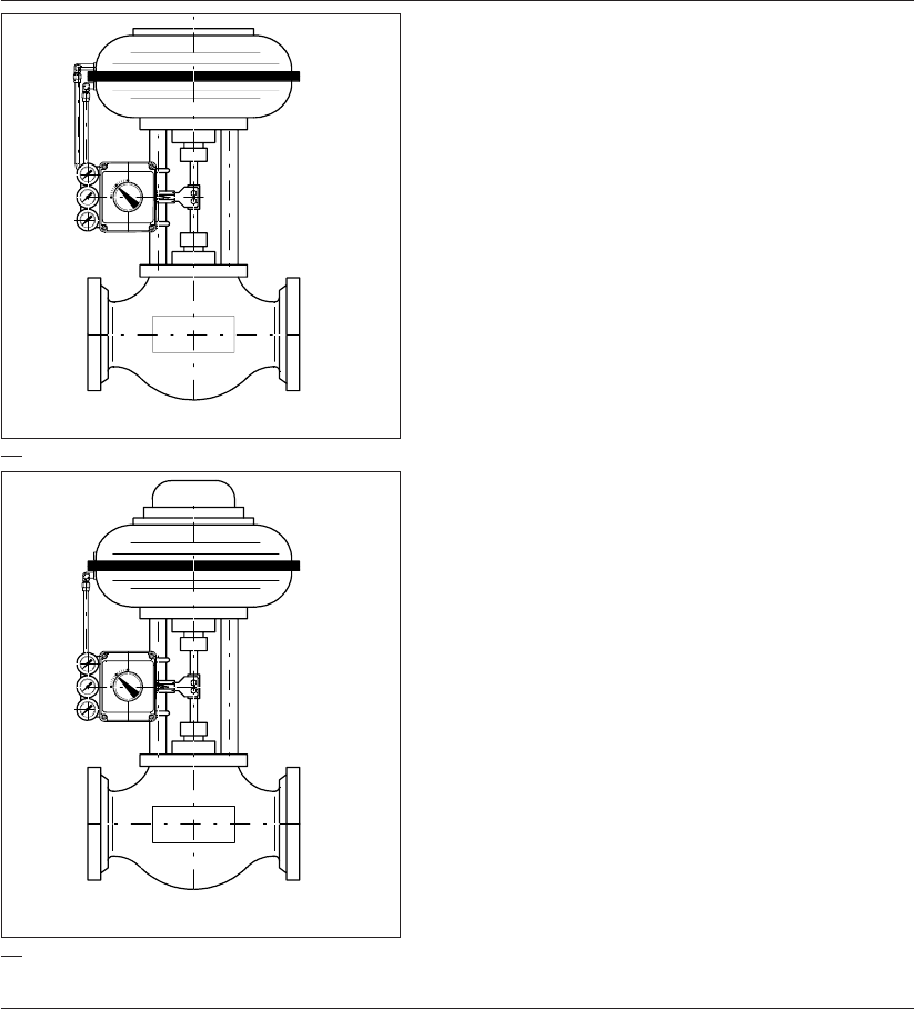
14 DOC,F20,EDN Rev.: -
3.2 Pneumatic Connections
Assuming a standard installation, with direct acting an increas-
ing signal to open the valve (rising spindle).
Before connecting any air supply make sure that the air
available is clean dry instrument air filtered to at least 25
microns.
3.2.1 Double acting
1. Connect an appropriate piece of air tubing between the port
1. on the positioner to the “A” port on the actuator. (The “A”
port is the one that, when air is applied to it, opens the
valve).
2. Connect an appropriate piece of air tubing between the port
2. on the positioner to the “B” port on the actuator. (The “B”
port is the one that when air is applied to it, closes the
valve).
3. If the positioner is required to meet enclosure rating IP54, be
sure that the sintered filter is in place at the “Exhaust” port.
4. Connect an air supply to the positioner port marked
“Supply”.
Note:
The same procedure is applicable to connect a double
acting actuator with reverse action, only select "Reverse
Action", see page 20.
For electrical installation, see page 16.
3.2.2 Single acting
1. Connect an appropriate piece of air tubing between the port
1. on the positioner to the “A” port on the actuator. (The “A”
port is the one that when air is applied to it, opens the
valve).
2. If the positioner is required to meet enclosure rating IP54, be
sure that the sintered filter is in place at the “Exhaust” port.
3. Connect an air supply to the positioner port marked
“Supply”.
Note:
The same procedure is applicable to connect a single
acting actuator with reverse action, only select "Reverse
Action", see page 22.
For electrical installation, see page 16.
3.0 Installation - Linear Actuators / Einbau - Hubantriebe / Montage - lineaire aandrijvingen
3.5
3.4
Double acting
Single acting

15DOC,F20,EDN Rev.: -
3.0 Installation - Linear Actuators / Einbau - Hubantriebe / Montage - lineaire aandrijvingen
3.2 Pneumatikanschlüsse
Es wird ausgegangen von einer direkt wirkenden Standardaus-
führung mit ansteigendem Signal zum Öffnen eines Ventils (mit stei-
gender Spindel).
Bevor die Luftversorgung angeschlossen wird, ist sicherzustellen,
daß die verfügbare Luft reine trockene Instrumentenluft ist, die
mit einer Feinheit von mindestens 25 Mikrometer gefiltert ist.
3.2.1 Doppeltwirkende Ausführung
1. Einen geeigneten Luftschlauch zwischen Anschluß 1 am
Stellungsregler und Anschluß "A" am Stellglied anbringen. (An-
schluß "A" ist der Anschluß, der bei Beaufschlagung mit Luft das
Ventil öffnet).
2. Einen geeigneten Luftschlauch zwischen Anschluß 2 am
Stellungsregler und Anschluß "B" am Stellglied anbringen. (An-
schluß "B" ist der Anschluß, der bei Beaufschlagung mit Luft das
Ventil schließt).
3. Die Luftversorgung an den Anschluß "SUPPLY" (Zuluft) des
Stellungsreglers anschließen.
4. An den Anschluß "Exhaust" (Entlüftung) sind Elemente anzu-
schließen, die IP54 gewährleisten (z.B. mitgelieferter Schall-
dämpfer).
Bemerkung:
Für einen doppeltwirkenden Antrieb mit Wirkung in umgekehr-
ter Richtung ist dem selben Verfahren zu folgen, mit dem Unter-
schied, daß die Einstellung "Umgekehrte Wirkungsrichtung" zu
wählen ist. Siehe Seite 21.
Elektrische Anschlüsse, siehe Seite 17.
3.2.2 Einfachwirkende Ausführung
1. Einen geeigneten Luftschlauch zwischen Anschluß 1 am
Stellungsregler und Anschluß "A" am Stellglied anbringen. (An-
schluß "A" ist der Anschluß, der bei Beaufschlagung mit Luft das
Ventil öffnet).
2. Die Luftversorgung an den Anschluß "SUPPLY" (Zuluft) des
Stellungsreglers anschließen.
3. An den Anschluß "Exhaust" (Entlüftung) sind Elemente anzu-
schließen, die IP54 gewährleisten (z.B. mitgelieferter Schall-
dämpfer).
Bemerkung:
Für einen einfachwirkenden Antrieb mit Wirkung in umgekehr-
ter Richtung ist dem selben Verfahren zu folgen, mit dem Unter-
schied, daß die Einstellung "Umgekehrte Wirkungsrichtung" zu
wählen ist. Siehe Seite 23.
Elektrische Anschlüsse, siehe Seite 17.
3.2 Pneumatische aansluitingen
Hierbij wordt uitgegaan van een standaard montage (voor di-
recte werking), waarbij een in intensiteit toenemend signaal de
afsluiter moet openen (omhoogkomende klepstang).
Alvorens lucht aan te sluiten, dient u te controleren of hier
sprake is van schone, droge instrumentenlucht die mini-
maal tot op 25 micron is gefilterd.
3.2.1 Dubbelwerkende uitvoering
1. Breng een passend stuk luchtleiding tussen poort 1 op de
klepstandsteller en poort “A” op de aandrijving aan. (Met
poort “A” wordt die poort bedoeld welke de klep opent wan-
neer lucht op deze poort wordt gezet.)
2. Breng een passend stuk luchtleiding tussen poort 2 op de
klepstandsteller en poort “B” op de aandrijving aan. (Met
poort “B” wordt die poort bedoeld welke de klep afsluit wan-
neer lucht op deze poort wordt gezet.)
3. Sluit lucht aan op de met “Supply” aangeduide poort van de
klepstandsteller.
4. Indien de klepstandsteller aan beschermingsklasse IP54
moet voldoen, dient b.v. de meegeleverde geluidsdemper in
de met “Exhaust” aangeduide poort te zijn aangebracht.
Opmerking:
De zelfde produre is van toepassing voor het aansluiten
van dubbelwerkende aandrijvingen met omgekeerde wer-
king. Echter, selecteer "Omgekeerde Werking" zie pagina
21.
Elektrische aansluitingen, zie pagina 17.
3.2.2 Enkelwerkende uitvoering
1. Breng een passend stuk luchtleiding tussen poort 1 op de
klepstandsteller en poort “A” op de aandrijving aan. (Met
poort “A” wordt die poort bedoeld welke de afsluiter opent
wanneer lucht op deze poort wordt gezet.)
2. Sluit lucht aan op de met “Supply” aangeduide poort van de
klepstandsteller.
3. Indien de klepstandsteller aan beschermingsklasse IP54
moet voldoen, dient b.v. de meegeleverde geluidsdemper in
de met “Exhaust” aangeduide poort te zijn aangebracht.
Opmerking:
De zelfde produre is van toepassing voor het aansluiten
van enkelwerkende aandrijvingen met omgekeerde wer-
king. Echter, selecteer "Omgekeerde Werking" zie pagina
23.
Elektrische aansluitingen, zie pagina 17.
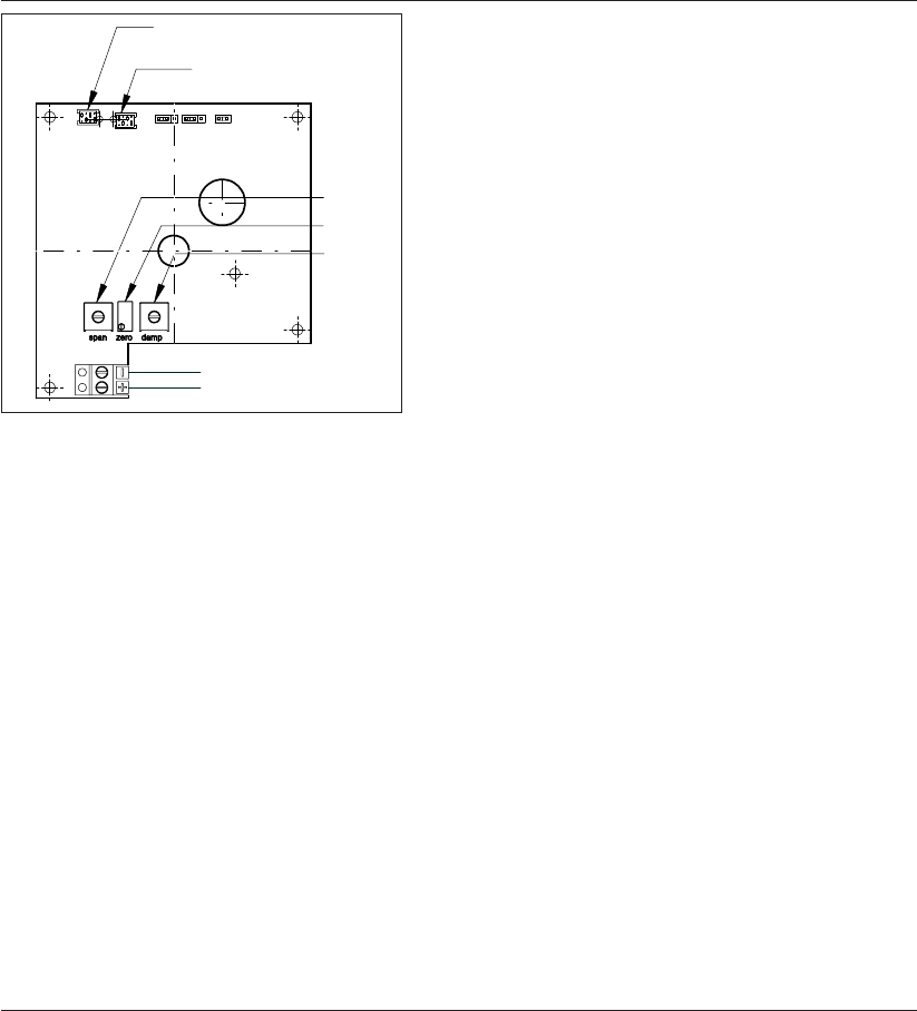
16 DOC,F20,EDN Rev.: -
4.1 Electrical Connections
Connect the 4 - 20 mA signal to the terminals (4) and (5),
making sure that the + and - are the correct way round. The
voltage is ~8 VDC.
4.2 Initial Setup - Zero, Range and Sensi-
tivity
The factory settings provide the positioner with an initial range
of settings that will allow the operation of positioners on most
applications.
Signal Input - 4 mA. - 20 mA.
Range - 0% to 100%
Control Function - Linear.
Action - Direct Acting.
(CCW with increasing Signal).
Three settings are provided on the main circuit board. These
allow adjustments of the zero, range and dead band (sensitiv-
ity).
Before making adjustments the positioner should be already
mounted on the valve/actuator, air supply connected, and a 4 -
20 mA.(¯8V.) signal connected to the signal input terminals.
4.3 Zero Setting
The zero resetting trimmer on the circuit board is marked
“Zero”. To change the position for the 4 mA signal, first set the
signal to 4 mA, then turn the trimmer screw until the desired
position is reached.
4.4 Range Setting
The positioner range is limited by the stroke position at the 20
mA. signal point. The range resetting trimmer on the circuit
board is marked “Span”. To change range, first set the signal to
20 mA, then turn the trimmer screw until the desired position is
reached.
4.5 Sensitivity Setting
A setting that is too high will cause the positioner to “hunt” with
difficulty in establishing a settled output. A setting that is too low
causes an output that is sluggish and lacking in response.
The sensitivity resetting trimmer on the circuit board is marked
“Damp”. To change sensitivity, first set the signal to an approxi-
mate mid point between 4 and 20 mA, then turn the trimmer
screw until the best result is reached.
Note:
The trimmers operate clockwise (CW) to increase, counter
clockwise (CCW) to decrease.
4.0 Electrical Connections and settings / Elektrische Anschlüsse und Einstellungen /
Elektrische aansluitingen en instellingen
Damp
Zero
Span
Input signal
Positioner coil
Feedback
potentiometer
= Empfindlichkeit
= Nullpunkt
= Bereich
= Eingangssignal
= Festspule
= Rückmelde-
potentiometer
= Gevoeligheid
= Nulpunt
= Bereik
= Ingangssignaal
= Standsteller Spoel
= Terugmeld
potentiometer
Positioner coil
Feeback potentiometer
Span
Zero
Damp
-4-20 mA
(~8 VDC Input signal)
+

17DOC,F20,EDN Rev.: -
4.1 Elektrische Anschlüsse
Anschließen des 4-20 mA Eingangssignales mit den Anschlüssen (4)
und (5). Es ist sicherzustellen, daß das + Signal richtig angeschlos-
sen ist. Die Spannung ist ~8 VDC
4.2 Anfangseinstellungen - Null, Bereich und
Totzone
Die Fabrikseinstellungen verschaffen dem Stellungsregler eine Rei-
he von Anfangseinstellungen, die den Betrieb von Stellungsreglern
für die meisten Anwendungen ermöglichen.
Signaleingang - 4 mA - 20 mA
Bereich - 0% bis 100%
Steuerfunktion - linear
Empfindlichkeit - 0,1%
Wirkung - Direkt wirkend (EDUL, mit ansteigendem
Signal)
Die Hauptplatine hat drei Einstellungsmöglichkeiten. Sie ermögli-
chen das Justieren vom Nullpunkt, Bereich und Empfindlichkeit. Vor
dem Justieren soll der Stellungsregler bereits am Ventil/Stellantrieb
montiert, die Luftversorgung angeschlossen und ein Signal von 4-20
mA (~8V) an den Eingangssignalklemmen angeschlossen sein.
4.3 Nullpunkteinstellung
Der Nullpunkt wird mit dem Einstellregler ,"zero" eingestellt. Das
Eingangssignal in den Stellungsregler wird auf 4mA abgesenkt.
Durch Verändern des Einstellreglers ,zero" wird der Punkt einge-
stellt, an dem der Antrieb gerade seine Bewegung beginnt.
4.4 Bereicheinstellung
Die Bereichseinstellung wird mit dem Einstellregler ,"span" vorge-
nommen. Das Eingangssignal in den Stellungsregler wird auf 20mA
erhöht. Durch Verändern des Einstellreglers ,span" wird der Punkt
eingestellt, an dem der Antrieb gerade seine Bewegung beginnt.
4.5 Einstellung der Empfindlichkeit
Die Empfindlichkeit wird mit dem Einstellregler ,"damp" eingestellt.
Eine zu hohe Empfindlichkeit kann zum Schwingen des Antriebes
führen. Eine zu kleine Einstellung bewirkt ein sehr langsames Rea-
gieren des Antriebes und eine zu große Totzone.
Die Empfindlichkeit kann man optimal einstellen, wenn man den
Stellungsregler mit ca. 12mA betreibt. Durch Drehen des Reglers
,damp" wird der Punkt eingestellt, an dem der Antrieb gerade nicht
mehr schwingt. Bei großen Antrieben kann man die volle Empfind-
lichkeit nutzen.
Vermerke:
Zum Anstieg die Abgleichschrauben mit dem Uhrzeigerlauf
(MUL), und zur Senkung entgegen dem Uhrzeigerlauf (EDUL)
drehen.
4.1 Elektrische aansluitingen
Sluit het 4-20 mA signaal aan op de klemmen (4) en (5). Let
erop dat de + en - op de juiste wijze worden aangesloten. Het
voltage is ~8VDC
4.2 Initiële instelling - nulpunt, bereik en
gevoeligheid
De klepstandstellers worden fabrieksmatig zodanig afgesteld,
dat zij voor de meeste toepassingen geschikt zijn.
Signaalingang - 4 - 20 mA
Bereik - 0% tot 100%
Regelfunctie - lineair
Gevoeligheid - 0,1%
Werking - direct werkend (Tegen de klok in ope-
nend bij een in intensiteit toenemend
signaal.)
De printplaat heeft drie instelmogelijkheden om het nulpunt, het
bereik en de gevoeligheid in te stellen. Voordat er gewijzigd
wordt, dient de klep-standsteller op de klep/aandrijving gemon-
teerd, lucht toegevoerd en een 4-20 mA (~8 V) signaal op de
signaalingangsklemmen aangesloten te worden.
4.3 Nulpunt instellen
Het nulpunt wordt met de trimmer “zero” ingesteld. Om de
stand voor het 4 mA signaal te veranderen, dient het signaal
eerst op 4 mA te worden ingesteld. Draai nu de trimmer totdat
de gewenste stand is bereikt.
4.4 Instellen van het bereik
Het bereik van de klepstandsteller wordt beperkt door de slag
die bij het 20 mA signaalpunt wordt gemaakt. Het bereik wordt
met de trimmer “span” ingesteld. Voor het veranderen van het
bereik dient het signaal eerst op 20 mA te worden ingesteld.
Draai nu de trimmer totdat de gewenste stand is bereikt.
4.5 Instellen van de gevoeligheid
Bij een te hoge instelwaarde zal de klepstandsteller zich onrus-
tig gedragen, waardoor het moeilijk wordt een vaste uitgaande
beweging te krijgen. Een te lage instelwaarde resulteert in een
trage uitgaande beweging.
Om de gevoeligheid te wijzigen, dient het signaal eerst te wor-
den ingesteld op 12 mA. Draai nu de trimmer "damp" totdat de
gewenste stand is bereikt. Bij grote aandrijvingen kan men de
volledige gevoeligheid benutten.
Opmerking:
Voor een hogere waarde de trimmers kloksgewijs draaien,
voor een lagere waarde de trimmers tegen de klok in
draaien.
4.0 Electrical Connections and settings / Elektrische Anschlüsse und Einstellungen /
Elektrische aansluitingen en instellingen
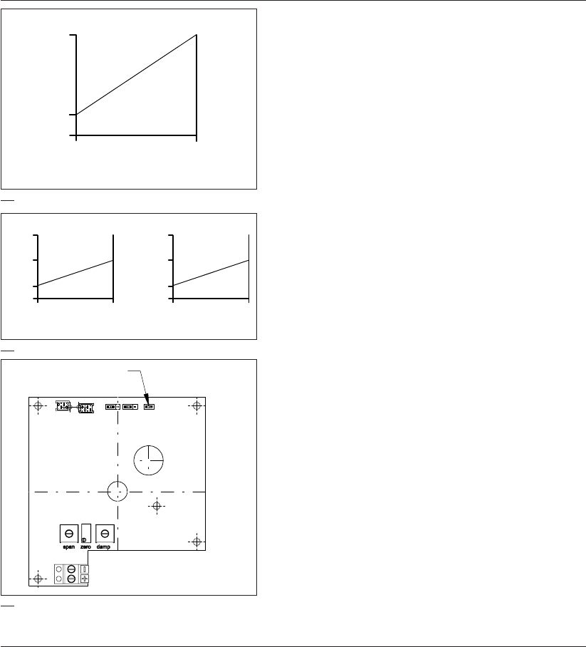
18 DOC,F20,EDN Rev.: -
4.6 Split range setting
To change the range from full range to split range remove the
split range jumper.
This way the positioner can be controlled either by a 4 to 12mA
signal or a 12 to 20mA signal.
The start point can be set at 4 or 12mA with the "ZERO"-
trimmer. The end point (range) can be set at 12 or 20mA with
the "SPAN"-trimmer.
Note:
1. These two adjustments are interrelated, so the zero may
have to be reset after changing the range and vice
versa.
2. To increase the signal turn the trimmer screws clock-
wise (CW). To decrease the signal turn the trimmer
screws counter clockwise (CCW).
20mA
4mA
0mA
Standard setting
0% 100%
20mA
12mA
4mA
0mA 0% 100%
20mA
12mA
4mA
0mA 0% 100%
Split range setting Setting of second positioner
4.1
4.2
4.3
4.0 Electrical Connections and settings / Elektrische Anschlüsse und Eeinstellungen /
Elektrische aansluitingen en instellingen
Standard setting =
Standard Einstellung =
Standaard instelling
Split range setting =
Einstellung für geteilten Eingangsbereich =
Instellen voor gesplitst bereik
Setting of second positioner =
Einstellung für den zweiten Stellungsregler =
Instelling voor tweede klepstandsteller
Split range jumper =
Jumper für geteilten Eingangsbereich =
Jumper voor gedeeld bereik
Split range jumper

19DOC,F20,EDN Rev.: -
4.6 Einstellung für geteilten Eingangsbereich
/ Split range
Durch Ziehen des einzelnen roten Jumpers auf der Leiterplatte kann
der Eingangssignalbereich halbiert werden. Damit kann man den
Stellungsregler entweder mit einem Eingangssignal von 4 bis 12mA
oder 12 bis 20mA betreiben.
Mit dem Einstellregler "ZERO" wird der jeweilige Startpunkt (4
oder 12mA) und mit "SPAN" das Bereichsende (12 oder 20mA) wie
oben beschrieben eingestellt.
Bemerkungen
1 Alle Einstellvorgänge beeinflussen sich. Deshalb muß ca. 2 bis
3 mal iterativ der Nullpunkt und der Bereich eingestellt wer-
den, um die maximale Genauigkeit zu erreichen.
2 Zum Anstieg die Abgleichschrauben mit dem Uhrzeigerlauf
(MUL), und zur Senkung entgegen dem Uhrzeigerlauf
(EDUL) drehen.
4.6 Instellen voor gesplitst bereik
Door het verwijderen van de rode jumper op de printplaat kan
het ingangssignaalbereik gehalveerd worden. Zo kan men de
klepstandsteller of met een ingangssignaal van 4 tot 12 mA of
12 tot 20 mA besturen.
Met de trimmers “zero” en “span” kan dan het beginpunt (4 of
12 mA) en het eindpunt (12 of 20 mA ) ingesteld worden.
Opmerking:
1 Deze instellingen zijn onderling verbonden. Dit houdt in
dat het nulpunt wellicht opnieuw moet worden inge-
steld nadat het bereik is gewijzigd. Het omgekeerde
geldt bij wijziging van het nulpunt.
2 Voor een hogere waarde moeten de trimmers met de
klok mee worden gedraaid, terwijl ze voor een lagere
waarde tegen de klok in gedraaid dienen te worden.
4.0 Electrical Connections and settings / Elektrische Anschlüsse und Eeinstellungen /
Elektrische aansluitingen en instellingen
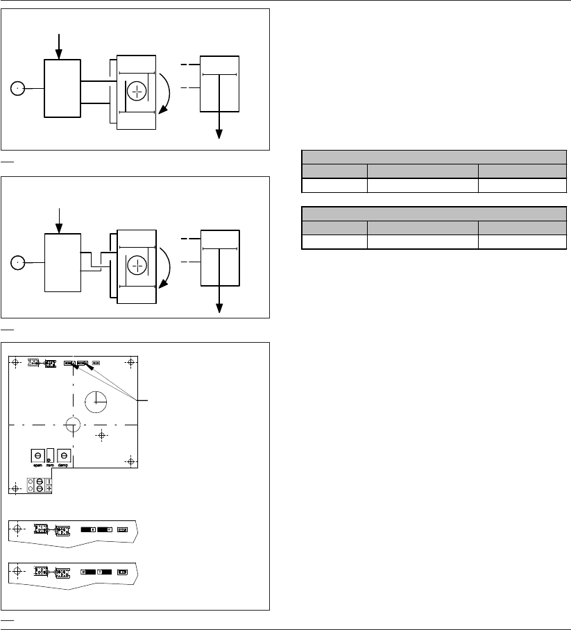
20 DOC,F20,EDN Rev.: -
Input
signal Rotary
actuator Linear
actuator
1
2
A
B
Close
B
A
Direct acting
Input
signal Rotary
actuator Linear
actuator
1
2
A
BClose
B
A
Reverse acting
5.1 Failure Modes - Double acting
The standard setup for double acting actuators is so that an
increasing input signal opens the valve. Signal failure, then,
moves the valve to the closed position . This may be changed
to “Open on signal failure” by changing the setup to REVERSE
ACTING.
The effect of signal and air failure depends on the way the air
connections and the potentiometer connections are made:
5.0 Failure Modes / Ausfallarten / Storingen
5.0
5.1
5.1.1 Changes for Reverse Acting
To change from the standard setup to reverse acting:
1. Change the tubing (see fig. 5.1).
2. Remove the cover.
3. Change the action jumper setting by setting both jumpers to
the right side (see fig. 5.2).
4. Replace the cover taking care that the “O” ring seal is in
place and the fixing screws are tightened correctly.
Action Air failure Signal failure
Direct Position not defined Closed
Action Air failure Signal failure
Reverse Position not defined Open
1. Direct actin
g
- Standard Setu
p
2. Reverse actin
g
Action "Direct"
Wirkungsweise "Direkt"
Werkwijze "Direkt"
Action "Reverse"
Wirkungsweise "Umgekehrt"
Werkwijze "Omgekeert"
5.2
- Jumper setting
"Action"
- Jumper Einstellung
"Wirkungsweise
- Jumper instelling
"Werkwijze"

21DOC,F20,EDN Rev.: -
5.0 Failure Modes / Ausfallarten / Storingen
5.1 Ausfallarten Doppeltwirkend
Die Standardeinstellung für doppeltwirkende Stellantriebe ist die,
bei der ein ansteigendes Gerätesignal das Ventil öffnet. Beim Ausfal-
len des Signals wird das Ventil geschlossen. Dies läßt sich ändern in
,Öffnen bei Signalausfall", indem die Einstellung auf REVERSE
ACTING (UMGEKEHRTE WIRKUNG) umgestellt wird.
Die Auswirkung eines Signal- und/oder Luftausfalls hängt davon
ab, wie Luft- und Potentiometeranschlüsse verbunden sind:
5.1 Storingen - dubbelwerkend
De standaardinstelling voor dubbelwerkende aandrijvingen is
zodanig dat een in intensiteit toenemend ingangssignaal de
klep opent. Door een signaalstoring wordt de klep gesloten. Dit
kan worden gewijzigd in “Open bij signaalstoring” door de in-
stelling te veranderen in OMGEKEERD WERKEND.
Het effect van een signaal- en luchtstoring is afhankelijk van de
wijze waarop de lucht- en potentiometeraansluitingen zijn ge-
maakt:
5.1.1 Umschaltung auf umgekehrte Wirkung
Zur Umschaltung von den Standardeinstellungen auf die umgekehr-
te Wirkung:
1. Die Schläuche ändern (siehe Abb. 5.1).
2. Den Deckel entfernen.
3. Wirkungsweise-Jumper auf umgekehrte Wirkung einstellen (Bei-
de Jumper auf die rechte Position stecken, siehe Abb. 5.2).
4. Den Deckel wieder einlegen, dabei darauf achten, daß die O-
Ringabdichtung in der richtigen Lage ist und die Fixierschrauben
ordnungsgemäß festgezogen werden.
5.1.1 Wijzigingen voor omgekeerde wer-
king
Om van standaardinstelling op de instelling voor omgekeerde
werking over te schakelen:
1. De luchtleidingen wijzigen (zie Afb. 5.1).
2. Verwijder het deksel.
3. Stel de "werkwijze"-jumpers in op omgekeerde werking
(Beide jumpers op de rechter positie plaatsen, zie Afb. 5.2).
4. Breng het deksel weer aan en controleer of de O-ring op de
juiste plaats zit en de bevestigingsschroeven correct zijn
aangehaald.
Wirkung Luftausfall Signalausfall
Direkt Stellung nicht definiert Zu
Wirkung Luftausfall Signalausfall
Umgekehrt Stellung nicht definiert Offen
1. Direkt wirkend - Standardeinstellung
2. Umgekehrt wirkend
Werking Luchtstoring Signaalstoring
Direkt Stand niet gedefinieerd Dicht
Werking Luchtstoring Signaalstoring
Omgekeerd Stand niet gedefinieerd Open
1. Direkt werkend - Standardeinstellun
g
2. Om
g
ekeerd werkend
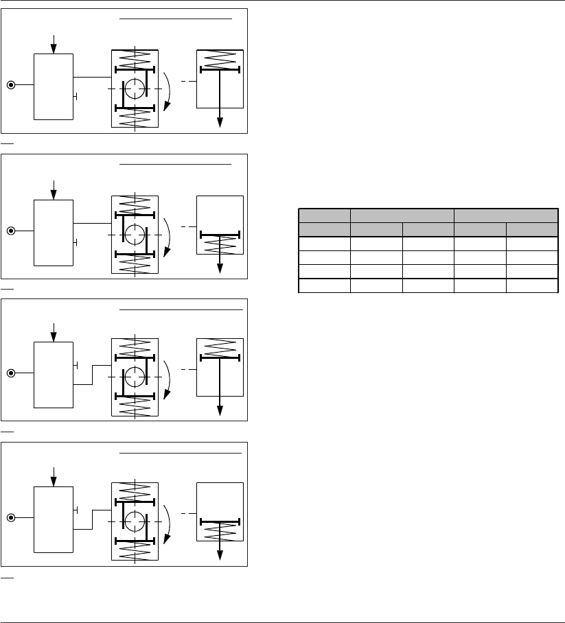
22 DOC,F20,EDN Rev.: -
5.2 Failure Modes - Single Acting (Spring
return)
Spring return actuators may be “fail open” or “fail close”
depending on what happens when the air fails. This air failure
mode must be built into the actuator and maintained when the
actuator is built onto the valve.
In addition both these air failure modes may be either direct
acting or reverse acting depending on what happens at the
positioner when the 4 - 20 mA. signal fails or is reduced to it’s
lowest level.
5.0 Failure Modes / Ausfallarten / Storingen
4. Fail Open - Reverse acting
Input
signal Rotary
actuator Linear
actuator
F20
1
2
A
Close
A
3. Fail Close - Reverse actingInput
signal Rotary
actuator Linear
actuator
F20
1
2
A
Close
A
2. Fail Open - Direct acting
Input
signal Rotary
actuator Linear
actuator
F20
1
2
A
Close
A
1. Fail Close - Direct acting
Input
signal Rotary
actuator Linear
actuator
F20
1
2
A
Close
A
5.3
5.4
5.5
5.6
5.2.1 Changes for Reverse Acting
To change from the standard setup to reverse acting:
1. Change the tubing (see fig. 5.3 to 5.6).
2. Plug the unused actuator port.
2. Remove the cover.
3. Change the action jumper setting by setting both jumpers to
the right side (see fig. 5.2).
4. Replace the cover taking care that the “O” ring seal is in
place and the fixing screws are tightened correctly.
Action
1 2 Air Signal
Direct A Block Close Close
Direct Block A Open Close
Reverse A Block Open Open
Reverse Block A Close Open
Air connection Failure
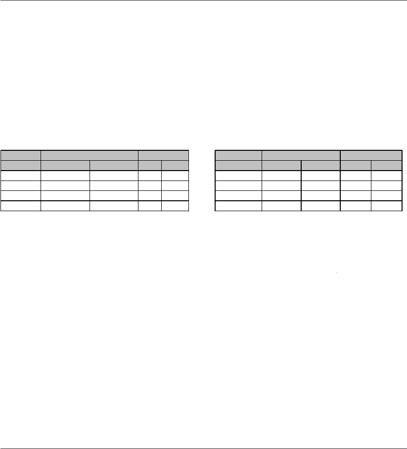
23DOC,F20,EDN Rev.: -
5.0 Failure Modes / Ausfallarten / Storingen
5.2 Ausfallarten - Einfachwirkend (Feder-
rückführung)
Stellungsantriebe mit Federrückführung können vom Typ ,bei Aus-
fall auf" oder ,bei Ausfall zu" sein, je nach dem, was passiert, wenn
die Luft ausfällt. Dieser Luftausfallmodus muß in den Stellantrieb
eingebaut werden und aufrechterhalten bleiben, wenn der Antrieb
auf die Armatur aufgebaut wird.
Außerdem können diese beiden Luftausfallmodi entweder direkt
wirkend oder umgekehrt wirkend sein, je nach dem, was mit dem
Stellungsregler passiert, wenn das (4-20 mA)-Signal ausfällt oder
auf sein niedrigstes Niveau abfällt.
5.2 Storingen- enkelwerkend (veerretour)
Veerbelaste aandrijvingen kunnen van het “bij storing ope-
nende” of het “bij storing sluitende” type zijn, al naar gelang wat
er bij een storing in de luchttoevoer gebeurt. Deze faalwijze
moet in de aandrijving worden opgenomen en gehandhaafd
blijven wanneer de aandrijving op de klep wordt gemonteerd.
Bovendien kunnen deze faalwijzen van het direct of omgekeerd
werkende type zijn, al naar gelang wat er met de klepstands-
teller gebeurt wanneer er een storing in het 4-20 mA signaal
optreedt of wanneer dit signaal zijn laagste waarde bereikt.
Door de luchtaansluiting te verwisselen en de niet gebruikte
aansluitpoort van de aandrijving af te pluggen kan geschakeld
worden tussen direct en omgekeerd werkend.
5.2.1 Umschaltung auf umgekehrte Wirkung
Zur Umschaltung von den Standardeinstellungen auf die umgekehr-
te Wirkung:
1. Die Schläuche ändern (siehe Abb. 5.3 bis 5.6)
2. Den nicht verwendeten Anschluß verschliessen.
3. Den Deckel entfernen.
4. Potentiometer-Jumper auf umgekehrte Wirkung einstellen (Beide
Jumper auf der rechten Position stecken, siehe Abb. 5.2).
5. Den Deckel wieder einlegen, dabei darauf achten, daß die O-
Ringabdichtung in der richtigen Lage ist und die Fixierschrauben
ordnungsgemäß festgezogen werden.
5.2.1 Wijzigingen voor omgekeerde wer-
king
Om van standaardinstelling op de instelling voor omgekeerde
werking over te schakelen:
1. De luchtleidingen wijzigen (zei Afb. 5.3 tot 5.6)
2 De niet gebruikte luchtaansluiting van de aandrijving
afpluggen.
3. Verwijder het deksel.
4. Stel de "werkwijze"-jumpers in op omgekeerde werking
(Beide jumpers op de rechter positie plaatsen, zie Afb. 5.2).
5. Breng het deksel weer aan en controleer of de O-ring op de
juiste plaats zit en de bevestigingsschroeven correct zijn
aangehaald.
Wirkung
1 2 Luft Signal
Direkt A verschliessen Zu Zu
Direkt verschliessen A Offen Zu
Umgekehrt A verschliessen Offen Offen
Umgekehrt verschliessen A Zu Offen
Anschlusse Ausfall
Werking Storing
1 2 Lucht Signaal
Direkt A Afpluggen Dicht Dicht
Direkt Afpluggen A Open Dicht
Omgekeerd A Afpluggen Open Open
Omgekeerd Afpluggen A Dicht Open
Luchtaansluitin
g
en

24 DOC,F20,EDN Rev.: -
6.0 General specifications / Allgemeine technische Daten / Algemene specificaties
General Specifications / Allgemeine technische Daten / Algemene specificaties
English Deutsch
Nederlands
Metric / Metrisch Imperial
Hysteresis Hysterese
Hysteresis
0.60%
Linearity Linearität
Lineariteit
1.00%
Air Flow Luftmenge
Luchtdoorlaat
210 Nl/min. (6 bar) 7.4 SCFM (87 psi)
Air Consumption Luftverbrauch
Luchtverbruik
10 Nl/min. (6 bar) 0.4 SCFM (87 psi)
Min. volume actuator Min. Volumen des Antriebs
Min. volume aandrijving
0.1 Nl 6.1 in3
Temperature Temperatur
Temperatuur
-20° / +80° C. -4° / +176°F
Enclosure Schutzart
Behuizing
IP 54 (option IP65). NEMA 3 (option NEMA 4)
Mounting Einbaunorm
Montage
VDI/VDE 3845 / IEC 534/6.
Air Entry Zuluftanschluß
Luchtaansluiting
G 1/4". 1/4" NPT
Air Supply Luftversorgung
Luchtdruk
1.4 - 8.6 bar. 21 to 125 psi
Electrical Entry Elektrischer Eingang
Elektrische aansluiting
PG 13.5 (option M20 x 1.5) 1/2"NPT
- Standard -Standard
- Standaard
2 wire/Draht/draads : 4 - 20 mA (~ 8VDC).
- Adjustable (for split
range)
- Einstellbar (für geteilten
Eingangsbereich)
- Instelbaar (voor gesplitst
bereik)
4-12mA / 12-20 mA
Resistance (at 20 mA) Widerstand (bei 20 mA)
Weerstand (bij 20 mA)
350 Ω
Ignite proof Zündschutzart
Explosie veilig
II 2 G EEx ib IIC T6
-acc. -nach
- volgens
TÜV 00 ATEX 1565
Only to be connected at Nur zum Anschluß an
Alleen aan te sluiten
certified intrinsically safe bescheinigte eigensichere
aan gecertificeerde
electrical circuit Stromkreise
intrinsiek veilige
elektrische circuits
Maximum values Höchstwerte
Maximum waardes
Ui = 28V
Ii = 100mA
Pi = 0,67
Effective inside Wirksame innere
Werkzame innere
0,1mH
inductivity Indukticität
inductiviteit
The effective inside Die wirksame innere
De werkzame innere
capacity is neglectable Kapazität ist vernach-
capaciteit is verwaar-
small lässigbar klein.
loosbaar klein
Media Non-lubricated instrument air, filtered at 25 micron.
Dew point should be 10°C (18°F) below enviromental temperatur.
Medien Instrumentluft, trocken, auf 25 Mikrometer gefiltert.
Taupunkt soll 10°C (18°F) niedriger sein als Betriebstemperatur.
Media Niet gesmeerde instrument lucht, gefilterd op 25 micron.
Dauwpunt moet 10°C (18°F) onder omgevingstemperatuur liggen.
Electrical Signal / Elektrisches Signal / Elektrisch signaal
Ex
p
losion
p
roo
f
version/Ex
p
losionsschutz Aus
f
ührun
g
/Ex
p
losieveili
g
euitvoerin
g
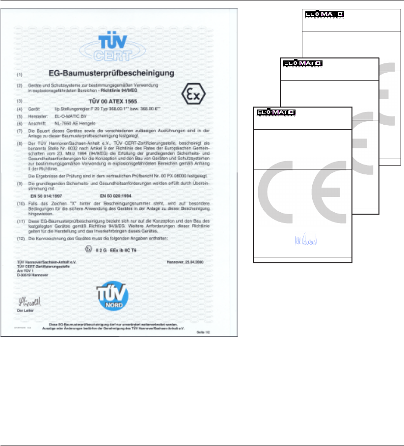
25DOC,F20,EDN Rev.: -
El-o-matic International B.V.
Asveldweg 19
7556 BR Hengelo
Netherlands
Verklaring
volgens
EMC-richtlijn 89/336/EG.
El-o-matic International B.V. verklaart hiermee dat de hieronder gespecificeerde
produkten voldoen aan de fundamentele veiligheids- en gezondheidseisen.
Beschrijving:Elektro-Pneumatische Klepstandsteller
Toepassingsgebied aandrijving Zie handleiding "Installation and Operation"
Type:F20
Certificaat:1023-99-EE-011 SLG Prüf- und Zertifizierungs
GmbH
Type:F40
Certificaat:Bolborn EMC Solutions dd. 21-12-1995
Serienummer:Iedere aandrijving wordt voorzien van een
serienummer
Van toepassing zijnde normen:EN 61000-3-2:1995
EN 61000-3-3:1995
EN 50081-1:1992
EN 50011:1991 Grenswaarde Klasse B
EN 50082-2:1995
H.G. Schwind
Algemeen Directeur
Alvorens de elektro-pneumatische klepstandsteller in gebruik wordt gesteld, dient de machine waarin de elektro-pneumatische
klepstandsteller wordt in- of opgebouwd, in overeenstemming te zijn met de bepalingen van de machinerichtlijn.
Hengelo, 30 mei 2000
6.1 Certificates / Zertifikate / Certifikaten
El-o-matic International B.V.
Asveldweg 19
7556 BR Hengelo
Netherlands
Erklärung
gemäß
Richtlinien in Sachen der elektromagnetischen Verträglichkeit 89/336/EG
El-o-matic International B.V. erklärt hiermit, daß die nachfolgend spezifizierten
Produkte den grundsätzlichen Anforderungen an die Sicherheit und den Gesund-
heitsschutz entsprechen.
Beschreibung:Elektropneumatischer Stellungsregler
Anwendungsbereich:Siehe Anleitung "Einbau und Inbetriebnahme"
Typ:F20
Zeugnis:1023-99-EE-011 SLG Prüf- und Zertifizierungs
GmbH
Type:F40
Zeugnis:Bolborn EMC Solutions dd. 21-12-1995
Seriennummer:Jeder Stellantrieb wird mit einer Seriennummer
versehen.
Anwendungsnormen:EN 61000-3-2:1995
EN 61000-3-3:1995
EN 50081-1:1992
EN 50011:1991 Grenzwerklasse B
EN 50082-2:1995
H.G. Schwind
Generaldirektor
Bevor der elektropneumatischer Stellungsregler in Betrieb gesetzt wird, muß die Maschine, in bzw. auf der der elektropneumatischer
Stellungsregler montiert wird, den Bestimmungen der Maschinenrichtlinie entsprechen.
Hengelo, den 30 Mai, 2000
El-o-matic International B.V.
Asveldweg 19
7556 BR Hengelo
Netherlands
Declaration
in accordance with
EMC directives 89/336/EC.
El-o-matic International B.V. hereby declares that the products specified below
meet the basic health and safety requirements.
Description:Electro-Pneumatic Positioner
Application area actuator:See manual "Installation and Operation"
Type:F20
Certificate 1023-99-EE-011 SLG Prüf- und Zertifizierungs
GmbH
Type:F40
Certificate Bolborn EMC Solutions dd. 21-12-1995
Serial No.:Each Electro-Pneumatic Positionerhas an
identifiable serial number
Applicable standards:EN 61000-3-2:1995
EN 61000-3-3:1995
EN 50081-1:1992
EN 50011:1991 Limit value class B
EN 50082-2:1995
H.G. Schwind
Managing Director
Before the electro-pneumatic positioner is put into operation, the machine into or onto which the electro-pneumatic positioner
will be installed, must comply with the stipulations of the machinery directive.
Hengelo, May 30th, 2000

26 DOC,F20,EDN Rev.: -
7.1 Introduction
The Position transmitter option provides a continuous position
indication by transmitting a 4 to 20 mA signal. This is propor-
tional to the actuators shaft position. The option is equipped
with trimmers for zero and span adjustment. These parameter
are not interrelated and adjusting one of these parameters will
not affect the other. Feedback is reversable from a 4-20 mA
signal to a 20-4 mA signal by means of two jumpers.
The option consists of an electronic card with a potentiometer.
The electronic card is mounted on top of the positioners main
board and fastened by three bolts. The wiring of the potentio-
meter is prewired.
Pos Qty Description
1 1 Position transmitter card
23Screw
3 3 Spacer
1. Remove cover and dial .
2. Turn positioner shaft CCW and potentiometer shaft CW until
they block (see fig. 7.0).
3. Place positioner transmitter option on the positioners main
board and fix the three screws (see fig. 7.1). Check posi-
tioner shaft for 90° rotation.
7.2 Installation
Before starting check the “Q-PT” kit to ensure that all the parts
are available.
Specifications;
Potmeter resistance : 50 KOhm
Umax : 30 VDC
Umin : 15 VDC
Signal out : 4 - 20 mA
7.0 Position transmitter option PTF20 / Stellungsgeberoption PTF20 / Positietransmitter
optie PTF20
7.0
7.1
27DOC,F20,EDN Rev.: -
7.1 Einführung
Diese Option sorgt mit Hilfe eines Signals von 4 bis 20 mA für eine
kontinuierliche Stellungsanzeige. Das Signal ist proportional zur Ab-
triebswellenposition. Diese Option ist mit Trimmern für die Null-
stellung und Bereich ausgestattet. Das Einstellen einer dieser Para-
meter hat keinen Einfluß auf den anderen Parameter. Die Rückmel-
dung kann von einem 4-20 mA-Signal in ein 20-4 mA-Signal umge-
wandelt werden mit Hilfe von zwei Jumper.
Diese Option besteht aus einer Elektronikkarte mit einem Potentio-
meter. Die Elektronikkarte wird oben auf die Grundplatine montiert
und mit drei Schrauben befestigt. Das Potentiometer ist vor-
verdrahtet.
7.1 Inleiding
De optionele positietransmitter zorgt voor een continue positie-
aanduiding door een 4 tot 20 mA signaal uit te zenden. Dit is
proportioneel aan de positie van de aandrijvings. Deze optie is
uitgerust met trimmers voor nulpunt en bereikinstelling. Het in-
stellen van een van deze parameters zal de ander niet beïn-
vloeden. Terugkoppeling is omkeerbaar van een 4-20 mA sig-
naal naar een 20-4 mA signaal door middel van een jumper-in-
stelling.
Deze optie bestaat uit een printplaat en een potentiometer. De
printplaat wordt op de hoofdkaart gemonteerd en met een bout
vastgezet. De potentiometer wordt op de eindschakelaarunit
gemonteerd. De bedrading van de potentiometer wordt op de
hoofdkaart aangesloten.
Pos. Anzahl Anzahl
1 1 Positionsgeberplatine
2 3 Schraube
3 3 Distanzplatte
7.2 Einbau
Vor dem Installieren überprüfen, ob alle Teile des “Q-PT”-Satzes
vorhanden sind.
7.2 Installatie
Controleer, alvorens te beginnen, of alle onderdelen van de “Q-
PT”-set beschikbaar zijn.
Pos Stuks Beschrijving
1 1 Positietransmitter
2 3 Schroef
3 3 Afstandstuk
1. Die Abdeckung und Skala entfernen.
2. Die Stellungsreglerwelle entgegen dem Uhrzeigerlauf und die
Potentiometerwelle mit dem Uhrzeigerlauf verdrehen (siehe Abb.
7.0) bis sie blocken.
3. Den Stellungsgeber auf der Hauptplatine platzieren und mit drei
Schrauben befestigen (siehe Abb. 7.1). Der Stellungsregler soll
jetzt um 90° verdrehbar sein.
1. Verwijder het deksel en de standindicatieschijf.
2. Draai de as van de standsteller tegen de klok in en de
potentiometeras met de klok mee (zie afb. 7.0) tot aan de
aanslag.
3. Plaats de positietransmitter op de hoofdkaart van de klep-
standsteller en bevestig de drie schroeven(zie afb. 7.1).
Kontroleer of de standsteller een 90° hoekverdraaiing maakt
Spezifikationen:
Potentiometer-Widerstand : 50 KOhm
Umax : 30 VDC
Umin : 15 VDC
Signalausgang : 4 - 20 mA
Specificaties:
weerstand potentiometer : 50 KOhm
Umax : 30 VDC
Umin : 15 VDC
signaal uit : 4 - 20 mA
7.0 Position transmitter option PTF20 / Stellungsgeberoption PTF20 / Positietransmitter
optie PTF20
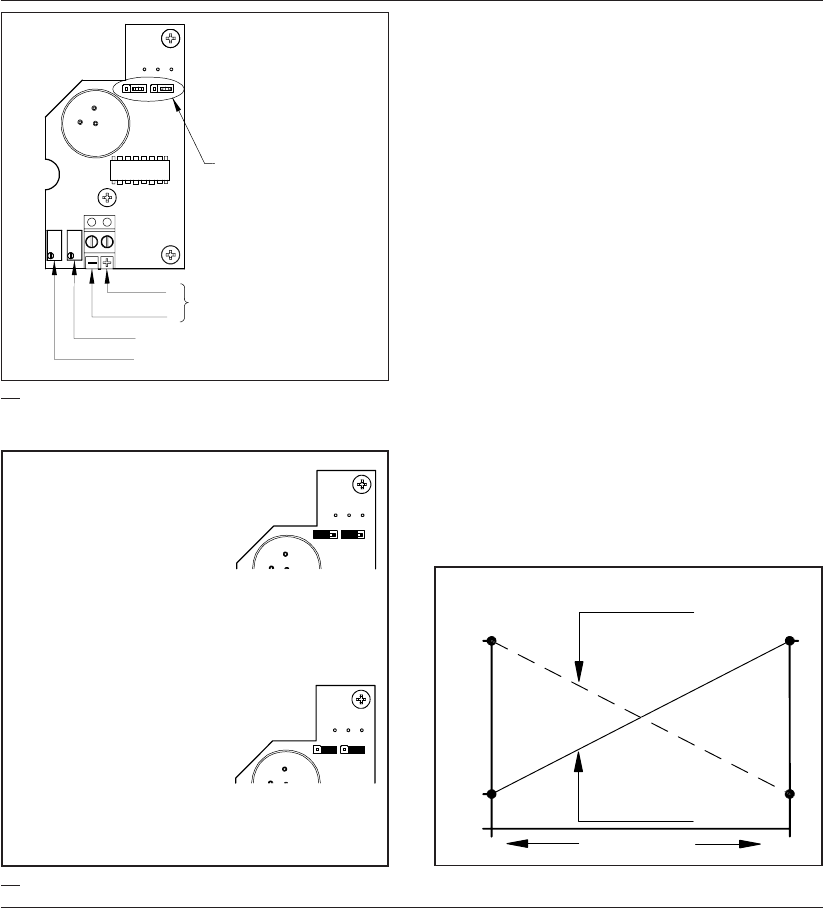
28 DOC,F20,EDN Rev.: -
4. Mount positioner on actuator (see chapter 2 or 3).
5. Make electrical connections as shown in fig. 7.2. Connect
also the control signal of the positioner as decribed in
chapter 4.
Wiring information
Wiring dimension : 1.5 mm 2 / 14 AWG
Tool : Screwdriver 0.6 x x 3.5 mm
Turning moment : 0.8 Nm / 7 in/lb
6. Set jumpers to “Direct” or “Reverse” to achieve a 4-20 mA or
a 20-4 mA feedback (see fig. 7.3).
7. Move the actuator pneumatically to the fully closed position.
Adjust the trimmer marked “Zero” to achieve a 4 mA reading
(20 mA in case of "Revers Action").
8. Move the actuator pneumatically to the fully open position.
Adjust the trimmer marked “Span” to achieve a 20 mA
reading (4 mA in case of "Revers Action").
Action "Direct" = 4-20mA at CCW
rotation
Wirkungsweise "Direkt" = 4-20mA bei
CCW Rotation
Werkwijze "Direkt" = 4-20mA bij rota-
tie tegen de klok in
Action "Reverse" = 20-4mA at CCW
rotation
Wirkungsweise "Umgekehrt" = 20-4mA
bei CCW Rotation
Werkwijze "Omgekeert" = 20-4mA bij
rotatie tegem de klok in.
7.0 Position transmitter option PTF20 / Stellungsgeberoption PTF20 / Positietransmitter
optie PTF20
Standard
"Direct" Action
7.2
7.3
-
+
Jumpersetting "Action"
Output signal:
Signal ; 4-20 mA
Voltage : 15-30 VDC
"Zero"
"Span"
"Revers" Action
Valve position
20 mA
4 mA
0 mA
0% 100%
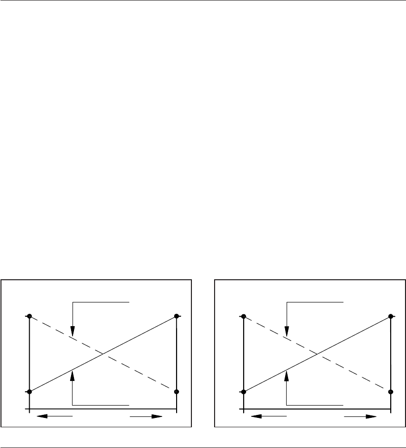
29DOC,F20,EDN Rev.: -
4. Den Stellungsregler mit dem Antrieb zusammenbauen (siehe Ka-
pitel 2 oder 3).
5. Die in Abb. 7.2 gezeigten Verbindungen herstellen. Ebenfalls das
Steuersignal des Stellungsreglers anschliessen wie beschrieben in
Kapitel 4.
Verdrahtungsinformation
Drahtabmessung : 1,5 mm 2 / 14 AWG
Werkzeug : Schraubenzieher 0,6 x x 3,5 mm
Anzugsdrehmoment : 0,8 Nm / 7 in/lb.
6. Die Jumper in der Position anbringen, die “Direkt” bzw. “Umge-
kehrt” entspricht, um eine 4-20 mA- oder 20-4 mA-Rück-
meldung zu bewirken (siehe Abb.7.3).
7. Den Antrieb pneumatisch in die völlig geschlossene Stellung fah-
ren. Den mit “Zero” bezeichneten Trimmer so einstellen, daß 4
mA angezeigt wird (20 mA bei Umgekehrter Wirkung).
8. Den Antrieb pneumatisch in die völlig offene Position fahren.
Den mit “Span” bezeichnetenTrimmer so einstellen, daß 20 mA
angezeigt wird (4 mA bei Umgekehrter Wirkung)..
4. De standsteller samenbouwen met de aandrijving (zie
hoofdstuk 2 of 3).
5. Maak de verbindingen zoals getoond in afb. 7.2. Sluit ook
het stuursignaal aan van de standsteller zoals beschreven
in hoofdstuk 4.
Bedradingsinformatie
Draadafmeting : 1,5 mm 2 / 14 AWG
Gereedschap : Schroevendraaier 0,6 x x 3,5 mm
Aanhaalmoment : 0,8 Nm / 7 in/lb
6. Stel de jumpers op “direkt” of “omgekeerde werking” in om
een terugkoppeling van 4-20 mA of van 20-4 mA te bereiken
(zie afb. 7.3).
7. Beweeg de aandrijving pneumatisch naar de positie volledig
gesloten. Stel de trimmer met de markering “nul” (zero) bij
om een 4 mA uitlezing te bereiken (20 mA bij omgekeerde
werking).
8. Beweeg de aandrijving pneumatisch naar de positie volledig
open. Stel de trimmer met de markering “spanwijdte” (span)
bij om een 20 mA uitlezing te bereiken (4 mA bij omge-
keerde werking).
7.0 Position transmitter option PTF20 / Stellungsgeberoption PTF20 / Positietransmitter
optie PTF20
Stanfard "Direkte"
Wirkungsweise
Standaard
"Direkte" werking
Omgekeerde
werking
Umgekehrte
Wirkungsweise
Armturen Stellung
Afsluiterstand
20 mA
4 mA
0 mA
0% 100%
20 mA
4 mA
0 mA
0% 100%

30 DOC,F20,EDN Rev.: -

31DOC,F20,EDN Rev.: -
INTERNATIONAL BENELUX GERMANY
EL-O-MATIC B.V. EL-O-MATIC Benelux EL-O-MATIC GmbH.
P.O. Box 223 P.O. Box 223 Postfach 460234 . D-47856 Willich
7550 AE Hengelo (O) 7550 AE Hengelo (O) Siemensring 112 . D-47877 Willich
Asveldweg 19 Asveldweg 11 Tel. +49 2154 499660
7556 BR Hengelo (O) 7556 BT Hengelo (O) Fax. +49 2154 427669
Holland Holland Löbtauer Strasse 65/67. D-01159 Dresden
Tel. +31 74 256 10 10 Tel. +31 74 256 10 20 Tel. +49 351 867 96 30
Fax. +31 74 291 09 38 Fax. +31 74 243 86 90 Fax. +49 351 867 96 50
UNITED KINGDOM SOUTH AFRICA VENEZUELA
EL-O-MATIC Ltd. EL-O-MATIC (Pty) Ltd. EL-O-MATIC INTERNATIONAL
16/17 Beeding Close Teknipark, 62 Lower Germiston Road Av. Principal Los Ruices
Southern Cross Trading Estate Heriotdale, Johannesburg Edif. stemo piso 1 Ofc. 1A
Bognor Regis P.O. Box 40348 Caracas
West Sussex, PO 22 9TS Cleveland 2022 Venezuela
Tel. +44 1243 830 363 Tel. +27 11 626 2880/1/2 Tel. +58 2 237 77 51
Fax. +44 1243 830 843 Fax. +27 11 626 2905 Fax. +58 2 238 9023
U.S.A. INDIA SINGAPORE
EL-O-MATIC U.S.A. Inc. EL-O-MATIC India Pvt Ltd. EL-O-MATIC Valve Actuators
135 English Street 296/A/1/5, St. Patrick’s Town Far East Pte Ltd.
Hackensack NJ 07601 Near Railway Crossing 28 Third Lok Yang Road
Tel. +1 201 489 5550 Hadapsar Industrial Estate Singapore 628016
Fax. +1 201 489 9171 Pune 411 013 Tel. +65 26 24 515
www.el-o-matic.com Tel. +91 212 672916 Fax. +65 2680028 / 770 80 80
Fax. +91 212 674465
