Emerson Fisher 8560 Data Sheet
2015-03-30
: Emerson Emerson-Fisher-8560-Data-Sheet-680503 emerson-fisher-8560-data-sheet-680503 emerson pdf
Open the PDF directly: View PDF ![]() .
.
Page Count: 12
www.Fisher.com
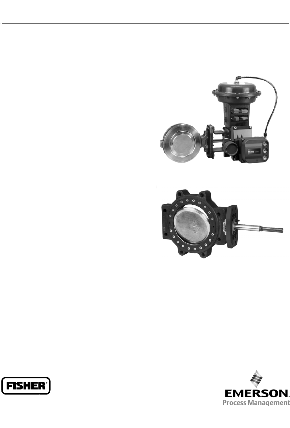
Fisherr8560 Eccentric Disc
Butterfly Control Valve
Fisher 8560 high-performance valves feature a
stainless steel disc with a soft or stainless steel seal
ring. Soft seals provide excellent sealing capabilities in
both directions. The pressure-assisted metal seal ring
provides excellent shutoff against pressure applied in
the recommended flow direction for both liquid and
gas applications.
The NOVEX and Phoenix III metal seals are available for
demanding applications requiring excellent shutoff
capabilities. The splined-shaft valve combines with a
variety of power actuators to form a reliable,
high-performancecontrolvalvesuitableforthrottling
applications requiring extremely low leakage rates.
Unless otherwise noted, all NACE references are to
NACE MR0175-2002.
Features
Exceptional Shutoff–Bidirectionalsoftsealring
with pressure assisting action (see figure 1) results
in exceptional shutoff per Class VI.
Excellent Flow Control–The eccentrically-mounted
disc design provides an approximate linear flow
characteristic and can be used for throttling or
on/off control applications through 90 degrees of
disc rotation.
Sour Service Capability–Trim and bolting materials
are available for applications involving sour service.
These constructions comply with the
recommendations of NACE MR0175-2002.
Improved Environmental Capabilities–The optional
ENVIRO-SEALpackingsystemisdesignedwith
improved sealing, guiding, and loading force
transmission. The ENVIRO-SEAL packing system can
control emissions to below the EPA (Environmental
Fisher 8560 Valve with 1052 Actuator and FIELDVUEt
DVC6200 Digital Valve Controller
W8299- 2
W6361
Fisher 8560 Single-Flange Valve
Protection Agency) limit of 100 ppm (parts per
million) for valves.
Integral Shaft-to-Body Bonding–Standard valve
construction includes conductive packing to
provide electrical bonding for hazardous area
applications.
Low Cost Maintenance–Individual disc/shaft
components can be replaced after disassembly due
to sleeve and taper pin connections (see figure 1).
8560 Valve
D102028X012
Product Bulletin
51.6:8560
February 2013

8560 Valve
D102028X012
Product Bulletin
51.6:8560
February 2013
2
Specifications
Valve Sizes and End Connection Styles
NPS J2, J3, J4, J6, J8, J10, and J12 valve
size available in Jwafer or Jsingle-flanged style
(NPS 2 available in wafer only)
Maximum Inlet Pressure(1)
Carbon Steel and Stainless Steel Valve Bodies:
Consistent with CL150 and 300 pressure-temperature
ratings per ASME B16.34 unless limited by material
temperature capabilities. NPS 2 is also consistent with
CL600
Maximum Pressure Drops(1)
Consistent with CL150 and 300 pressure-temperature
ratings per ASME B16.34 except for PTFE, UHMWPE
and Phoenix III seals which are derated at some higher
pressure-temperature values. Refer to figure 3
Shutoff Classifications
JPTFE, Reinforced PTFE, and UHMWPE(3) Seals:
Bidirectional shutoff to Class VI per ANSI/FCI 70-2and
IEC 60534-4.Seefigure2
JNPS 2 Metal Seal: Bidirectional shutoff. 0.001% of
maximum valve capacity (1/10) of Class IV per
ANSI/FCI 70-2 and IEC 60534-4. Maximum Pressure
drop is 51 bar (740 psi) forward and 6.9 bar (100 psi)
reverse
JNOVEX Seal: For NPS 3 through 12. Unidirectional
shutoff is 0.0001% of maximum valve capacity (1% of
Class IV). See figure 2
JPhoenix III Seal: For NPS 3 through 12. Bidirectional
shutoff to Class VI per ANSI/FCI 70-2 and IEC 60534-4.
Seefigure2.FortheoptionalPhoenixIIIFire-Tested
seal(2), consult your Emerson Process Management
sales office
Construction Materials
Refer to table 2 for standard material selections and
component temperature ranges
Material Temperature Capabilities(1)
PTFE and Reinforced PTFE Seals: -46 to 232_C
(-50 to 450_F)
UHMWPE(3) Seal: -18 to 93_C(0to200_F)
NPS 2 Metal Seal: -46 to 538_C(-50 to 1000_F)
NOVEX Seal: -46 to 538_C(-50to1000_F)
Phoenix III: -46 to 232_C (-50 to 450_F)
Flow Characteristic
Approximately linear
Flow Direction
Refer to figure 4
Flow Coefficients
See table 1 and Fisher Catalog 12
Flow Coefficient Ratio(4)
100 to 1
Noise Levels
See Catalog 12 for sound pressure level prediction
Disc Rotation
Clockwise to close (when viewing from the drive shaft
end) through 90 degrees of disc rotation
Actuator/ Valve Action
With a diaphragm or piston rotary actuator, the valve
action is field-reversible. Refer to information
provided in the Installation section and figure 4
Valve Classification
Face-to-face dimensions of NPS 3 through 12 valves in
CL150 or 300, meets API 609 or MSS-SP68 standards
for face-to-face dimensions of wafer-style and
single-flange valves (see figure 6)
(continued)

8560 Valve
D102028X012
Product Bulletin
51.6:8560
February 2013
3
Specifications (continued)
Approximate Weights
VALVE SIZE,
NPS
WAFER STYLE SINGLE FLANGE
CL150 CL300 CL150 CL300
kg
2(5)
3
4
4
5
9
4
6
10
---
6
11
---
11
18
6
8
10
12
13
21
34
49
15
24
44
64
16
27
40
62
27
42
78
131
Pounds
2(5)
3
4
9.5
10
19
9.5
13
23
---
14
24
---
25
39
6
8
10
12
29
47
75
107
33
53
96
141
35
59
88
137
59
93
172
288
Mating Flange Capabilities
All sizes compatible with CL150 and 300, NPS 2 also
compatible with CL600, flanges (schedule 80 or
lighter, see figure 6, Dimension M)
Shaft Diameters
Seefigure6
ENVIRO-SEALtPacking
This optional JPTFE or Jgraphite packing system
provides improved sealing, guiding, and transmission
of loading force to control liquid and gas emissions
(see figure 5). See Bulletin 59.3:041 ENVIRO-SEAL
Packing Systems for Rotary Valves for more
information.
1. The pressure-temperature limits in this bulletin and any applicable standard or code limitation should not be exceeded.
2. For component selection and applicable fire-tested standards and codes, consult your Emerson Process Management sales office (see table 2).
3. UHMWPE stands for ultra high molecular weight polyethylene.
4. Ratio of maximum flow coefficient to minimum usable flow coefficient.
5. Weight of the CL600 NPS 2 valve is the same as the CL150 and CL300 values.
Installation
It is recommended that the valve drive shaft be
mounted in a horizontal position as shown in the
figures on page 1. Operating conditions may require
specific valve/actuator fail action, styles, positions and
flow direction. Valves with NOVEX seal rings require
mounting in the reverse flow direction. Refer to figure
4. Large valve/actuator assemblies may require
additional support because of their combined weight.
Fail Action: For actuators with spring returns, spring
fail action is available for push-down-to-open or
push-down-to-close valve action. The valve action is
field reversible.
For assistance in selecting the valve/actuator
mounting suited to your application, consult your
Emerson Process Management sales office.
Dimensions for wafer-style and single-flanged valves
are shown in figure 6.

8560 Valve
D102028X012
Product Bulletin
51.6:8560
February 2013
4
Table 1. Flow Coefficients(1)
VALVE SIZE,
NPS
CvFORWARD FLOW WITH DISC WIDE OPEN (90 DEGREES ROTATION)
CL150 CL300
2
3
4
6
8
10
12
80.2
237
499
1250
2180
3600
5400
80.2
237
488
1110
2070
3480
5130
1. See Fisher Catalog 12 for a complete listing of flow coefficients.
Table 2. Construction Material Temperature Limits
COMPONENTS AND MATERIALS OF CONSTRUCTION TEMPERATURE LIMITS
_C_F
Valve Body Material
Carbon Steel
CF8M
CG8M
-29 to 427
-198 to 538
-198 to 538
-20 to 800
-325 to 1000
-325 to 1000
Disc Material
CF8M
CG8M
-198 to 538
-198 to 538
-325 to 1000
-325 to 1000
Shaft Material
S20910
S17400
-198 to 538
-62 to 427
-325 to 1000
-80 to 800
Bearing Material
PEEK / PTFE lined
Metal (NOVEX or Phoenix III only)
-73 to 260
-198 to 538
-100 to 500
-325 to 1000
Packing Material
PTFE V-Rings
Graphite rings (NOVEX or Phoenix III only)
-46 to 232
-198 to 538
-50 to 450
-325 to 1000
Seal Ring
PTFE (Standard) Soft Seal Ring -46 to 232 -50 to 450
Reinforced PTFE Soft Seal Ring -46 to 232 -50 to 450
UHMWPE Soft Seal Ring -18 to 93 0 to 200
NOVEX Metal Seal Ring -46 to 538 -50 to 1000
NPS2MetalSealring -46 to 538 -50 to 1000
Phoenix III MetalSealRing
Fluorocarbon backup ring -40 to 232 -40 to 450
Phoenix III Fire-Tested(1)
MetalSealRing
Fluorocarbon backup ring
(Specify metal bearings and graphite packing)
-40 to 232 -40 to 450
1. For component selection and applicable fire-tested standards and codes, consult your Emerson Process Management sales office.
8560 Valve
D102028X012
Product Bulletin
51.6:8560
February 2013
5
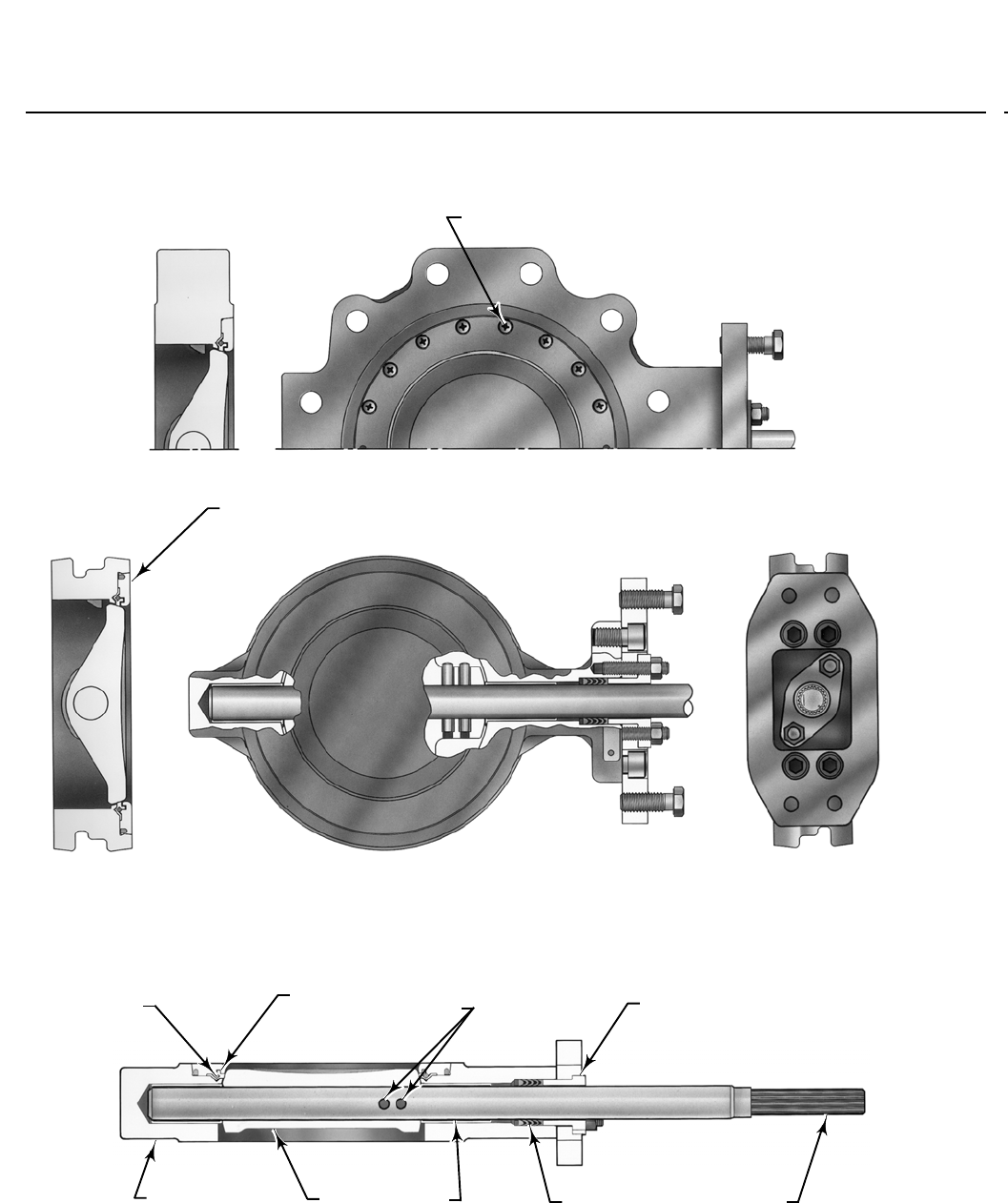
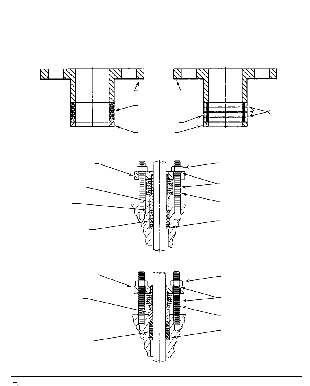
Figure 1. Typical Valve Construction
RETAINER RING
SCREWS
SINGLE-FLANGED STYLE
W6233-1
SPRING SEAL
RING
TAPER PINS
AND HOLLOW
PINS PACKING FOLLOWER
VALVE BODY DISC BEARING PTFE V-RING
PACKING
SPLINED SHAFT
W6235-2
W6234-1
RETAINER RING
(PRESSED-IN)
WAFER STYLE
8560 Valve
D102028X012
Product Bulletin
51.6:8560
February 2013
6
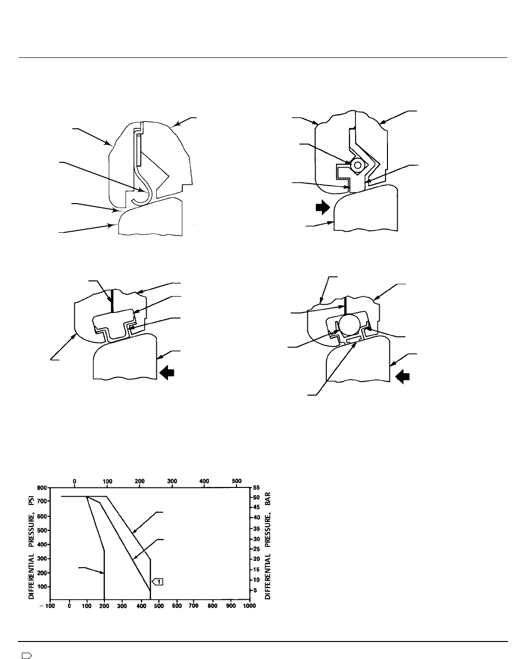
Figure 2. Available Seal Configuration
NOVEX METAL SEAL PHOENIX III METAL SEAL
PTFE, REINFORCED PTFE, AND UHMWPE SEALS
BIDIRECTIONAL SEAL
UNIDIRECTIONAL SEAL BIDIRECTIONAL SEAL
A6301-1
RETAINING
RING
SPRING
PRESSURE-
ASSISTED
SEAL
HIGH
PRESSURE
SHUTOFF
DISC FACE
VALVE
BODY
SEAL
RING
GRAPHITE
GASKET
RETAINING
RING
VALVE BODY
PRESSURE-
ASSISTED SEAL
SEAL RING
HUB SIDE
OF DISC
HIGH
PRESSURE
SHUTOFF
RETAINING
RING
GRAPHITE
GASKET
VALVE
BODY
SEAL RING
HUB SIDE
OF DISC
HIGH
PRESSURE
SHUTOFF
BACKUP
O-RING
RESILIENT
INSERT
RETAINING
RING
PRESSURE-ASSISTED
SEAL
HIGH PRESSURE
SHUTOFF
DISC
FACE
VALVE BODY
B1558-3/IL
NPS 2 METAL SEAL
Figure 3. Maximum Pressure-Temperature Ratings
1
Note:
Temperature limitations do not account for the additional limitations imposed by the backup ring used with this seal. To
determine the effective temperature limitation of the appropriate seal/backup ring combination, refer to table 2.
A6306-2
OPERATING TEMPERATURE, _C
OPERATING TEMPERATURE, _F
UHMWPE
SEAL
PHOENIX III SEAL
WITH PTFE INSERT
PTFE AND REINFORCED
PTFE SEAL
8560 Valve
D102028X012
Product Bulletin
51.6:8560
February 2013
7
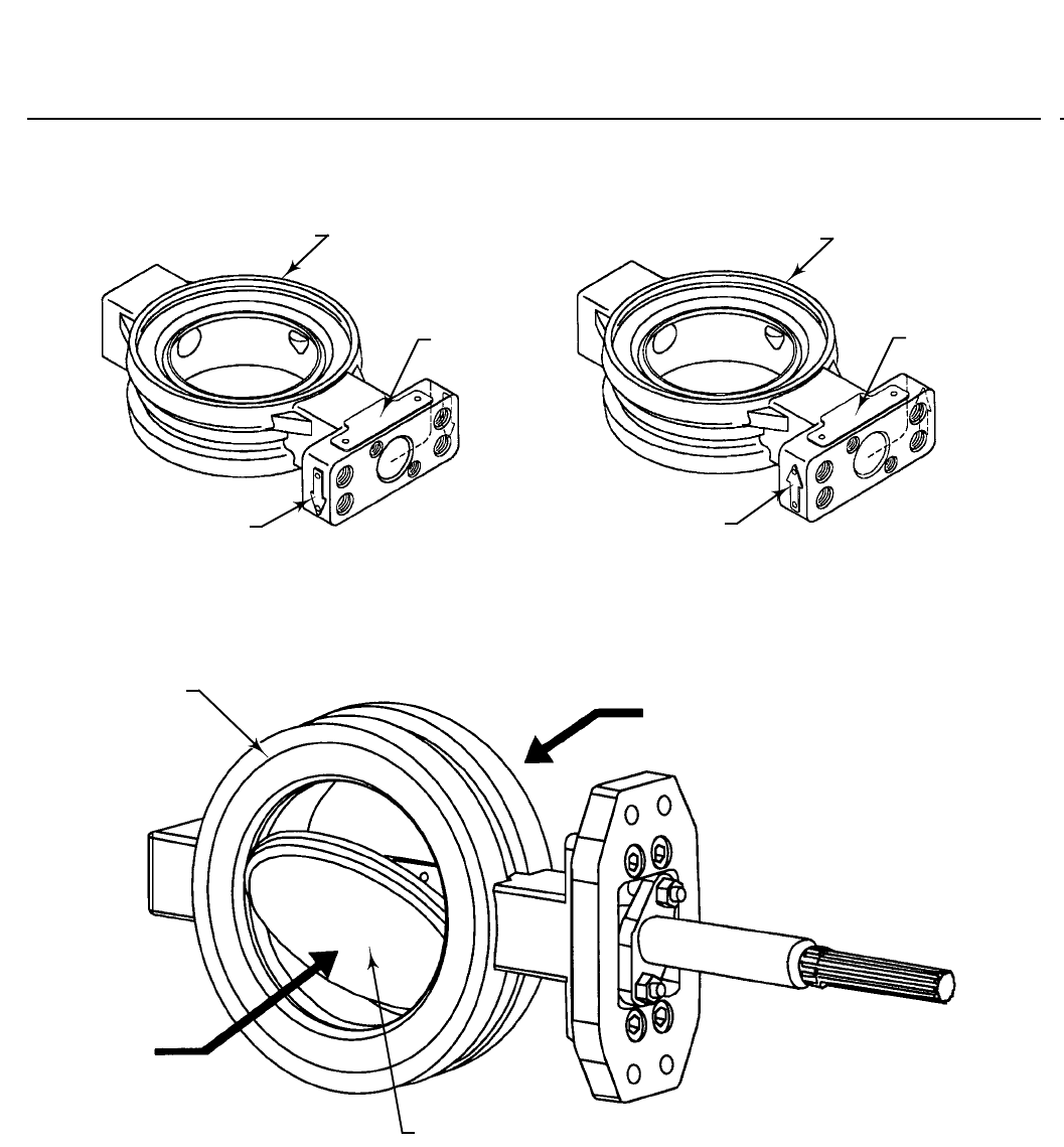
Figure 4. Actuator Mounting
RETAINER RING SIDE
MFG LABEL
FLOW ARROW
RETAINER RING SIDE
MFG LABEL
FLOW ARROW
ARROW SHOWS PREFERRED FLOW DIRECTION FOR SOFT SEALS AND
NPS 2 METAL SEALS
FORWARD FLOW REVERSE FLOW
ARROW SHOWS FLOW DIRECTION FOR NOVEX METAL SEAL, AND
PREFERRED FLOW DIRECTION FOR PHOENIX METAL SEAL
75B1181-A
A6882
RETAINER RING
FORWARD
FLOW
REVERSE
FLOW
FACE SIDE OF DISC
8560 Valve
D102028X012
Product Bulletin
51.6:8560
February 2013
8
Figure 5. Typical Packing Arrangement
Note:
Includes zinc washers for graphite ribbon packing only.
1
PACKING
FOLLOWER
PACKING SET
PACKING RING
PACKING BOX
RING
PACKING FLANGE
SPRING PACK
ASSEMBLY
ANTI-EXTRUSION
RING
PACKING SET
PACKING FLANGE
NUT
LUBRICANT
PACKING FLANGE
STUD
PACKING BOX
RING
PACKING FLANGE
SPRING PACK
ASSEMBLY
PACKING SET
PACKING FLANGE
NUT
LUBRICANT
PACKING FLANGE
STUD
PACKING BOX
RING
PTFE V-RING PACKING GRAPHITE RIBBON PACKING
ENVIRO-SEAL PTFE PACKING SYSTEM
ENVIRO-SEAL GRAPHITE PACKING SYSTEM
STANDARD PACKING
C0785*A
1
8560 Valve
D102028X012
Product Bulletin
51.6:8560
February 2013
9
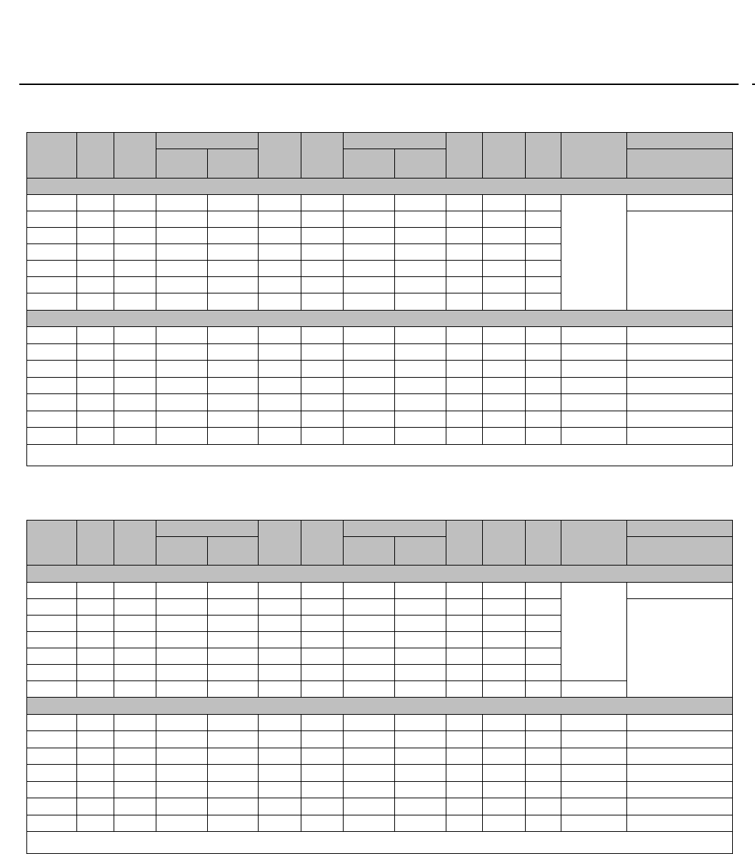
Table3.CL150ValveDimensions
Valve
Size,
NPS
A E
G
K M(2)
R
S(1) T U W
Y
Wafer
Style
Single
Flange
Wafer
Style
Single
Flange
Single Flange
Only
mm
245 188 102 --- 102 --- 103 --- 12.7 117 ---
See thread
informatio
nbelow
---
348 188 70 79 121 73 133 189 12.7 117 ---
See thread
information
below
454 188 86 102 143 97 171 219 15.9 117 ---
657 214 121 129 172 146 219 273 19.1 152 32
864 214 155 157 200 191 272 333 25.4 152 32
10 71 208 186 198 254 238 330 406 31.8 235 46
12 81 208 222 230 279 284 387 476 38.1 235 46
Inches
21.78 7.38 4.0 --- 4.00 1.88 4.06 --- 1/2 4.62 --- 1/2-13 ---
31.88 7.38 2.75 3.12 4.00 2.88 5.25 7.44 1/2 4.62 --- 1/2-13 5/8-11 4-holes
42.12 7.38 3.38 4.00 5.62 3.81 6.75 8.62 5/8 4.62 --- 1/2-13 5/8-11 8-holes
62.25 8.44 4.75 5.06 6.75 5.75 8.62 10.75 3/4 6.00 1.25 1/2-13 3/4-10 8-holes
82.50 8.44 6.12 6.19 7.88 7.50 10.69 13.12 16.00 1.25 1/2-13 3/4-10 8-holes
10 2.81 8.19 7.31 7.81 10.00 9.38 13.00 16.00 1-1/4 9.25 1.81 5/8-11 7/8-9 12-holes
12 3.19 8.19 8.75 9.06 11.00 11.19 15.25 18.75 1-1/2 9.25 1.81 5/8-11 7/8-9 12-holes
1. This nominal valve shaft diameter is the shaft diameter through the packing box. Use this diameter when selecting Fisher actuators.
2. Disc chordal swing diameter at valve face. Please verify with piping.
Table 4. CL300 Valve Dimensions
Valve
Size,
NPS
A E
G
K M(2)
R
S(1) T U W
Y
Wafer
Style
Single
Flange
Wafer
Style
Single
Flange
Single Flange
Only
mm
245 188 102 --- 102 --- 103 --- 12.7 117 ---
See thread
informatio
nbelow
---
348 188 89 95 137 73 132 206 15.9 117 ---
See thread
information
below
454 214 114 121 165 97 162 238 19.1 152 32
659 214 146 152 197 146 221 308 25.4 152 32
873 208 175 183 235 188 276 375 31.8 235 46
10 83 208 232 229 268 233 330 438 38.1 235 46
12 92 365 308 308 308 278 389 508 44.5 273 51 21
Inches
21.78 7.38 4.00 --- 4.00 1.88 4.06 --- 1/2 4.62 --- 1/2-13 ---
31.88 7.38 3.50 3.75 5.38 2.88 5.19 8.12 5/8 4.62 --- 1/2-13 3/4-10 8-holes
42.12 8.44 3.50 4.75 6.50 3.81 6.38 9.38 3/4 6.00 1.25 1/2-13 3/4-10 8-holes
62.31 8.44 5.75 6.00 7.75 5.69 8.69 12.12 16.00 1.25 1/2-13 3/4-10 12-holes
82.88 8.19 6.88 7.19 9.25 7.38 10.88 14.75 1-1/4 9.25 1.81 5/8-11 7/8-9 12-holes
10 3.25 8.19 9.12 9.00 10.56 9.19 13.00 17.25 1-1/2 9.25 1.81 5/8-11 1-8 16-holes
12 3.61 14.00 12.12 12.12 12.12 10.94 15.31 20.00 1-3/4 10.75 2.00 0.82 1-1/8-816-holes
1. This nominal valve shaft diameter is the shaft diameter through the packing box. Use this diameter when selecting Fisher actuators.
2. Disc chordal swing diameter at valve face. Please verify with piping.
8560 Valve
D102028X012
Product Bulletin
51.6:8560
February 2013
10
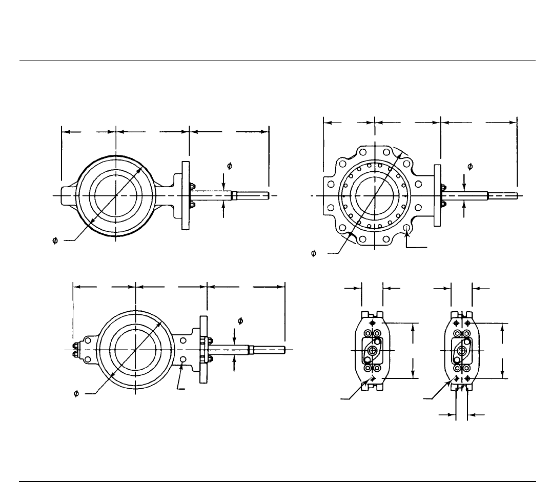
Figure 6. Typical Valve Dimensions (also see tables 3 and 4)
Note:
Disc chordal swing diameter at valve face is M. Please verify clearance with piping.
WAFER-STYLE VALVE
SINGLE-FLANGE VALVE
NPS 12 CL300
WAFER-STYLE VALVE
TYPICAL VALVE MOUNTING
14B0833-B
14B0835-D
B2433
NPS 6 THROUGH 12 CL150
NPS 4 THROUGH 12 CL300
NPS 2 THROUGH 4 CL150
NPS 2 AND 3 CL300
G
G
G
K
K
K
E
E
E
SS
S
R
R
R
AA
WW
TT
U
Y
4 CLEARANCE HOLES

8560 Valve
D102028X012
Product Bulletin
51.6:8560
February 2013
11

8560 Valve
D102028X012
Product Bulletin
51.6:8560
February 2013
12
Emerson Process Management
Marshalltown, Iowa 50158 USA
Sorocaba, 18087 Brazil
Chatham, Kent ME4 4QZ UK
Dubai, United Arab Emirates
Singapore 128461 Singapore
www.Fisher.com
The contents of this publication are presented for informational purposes only, and while every effort has been made to ensure their accuracy, they arenot
to be construed as warranties or guarantees, express or implied, regarding the products or services described herein or their use or applicability. All sales are
governed by our terms and conditions, which are available upon request. We reserve the right to modify or improve the designs or specifications of such
products at any time without notice.
E1994, 2013 Fisher Controls International LLC. All rights reserved.
Fisher, FIELDVUE, and ENVIRO-SEAL are marks owned by one of the companies in the Emerson Process Management business unit of Emerson Electric Co.
Emerson Process Management, Emerson, and the Emerson logo are trademarks and service marks of Emerson Electric Co. All other marks are the property
of their respective owners.
Neither Emerson, Emerson Process Management, nor any of their affiliated entities assumes responsibility for the selection, use or maintenance
of any product. Responsibility for proper selection, use, and maintenance of any product remains solely with the purchaser and end user.
