Emerson Fisher Baumann 24003 Data Sheet
2015-03-30
: Emerson Emerson-Fisher-Baumann-24003-Data-Sheet-680712 emerson-fisher-baumann-24003-data-sheet-680712 emerson pdf
Open the PDF directly: View PDF ![]() .
.
Page Count: 8
www.Fisher.com
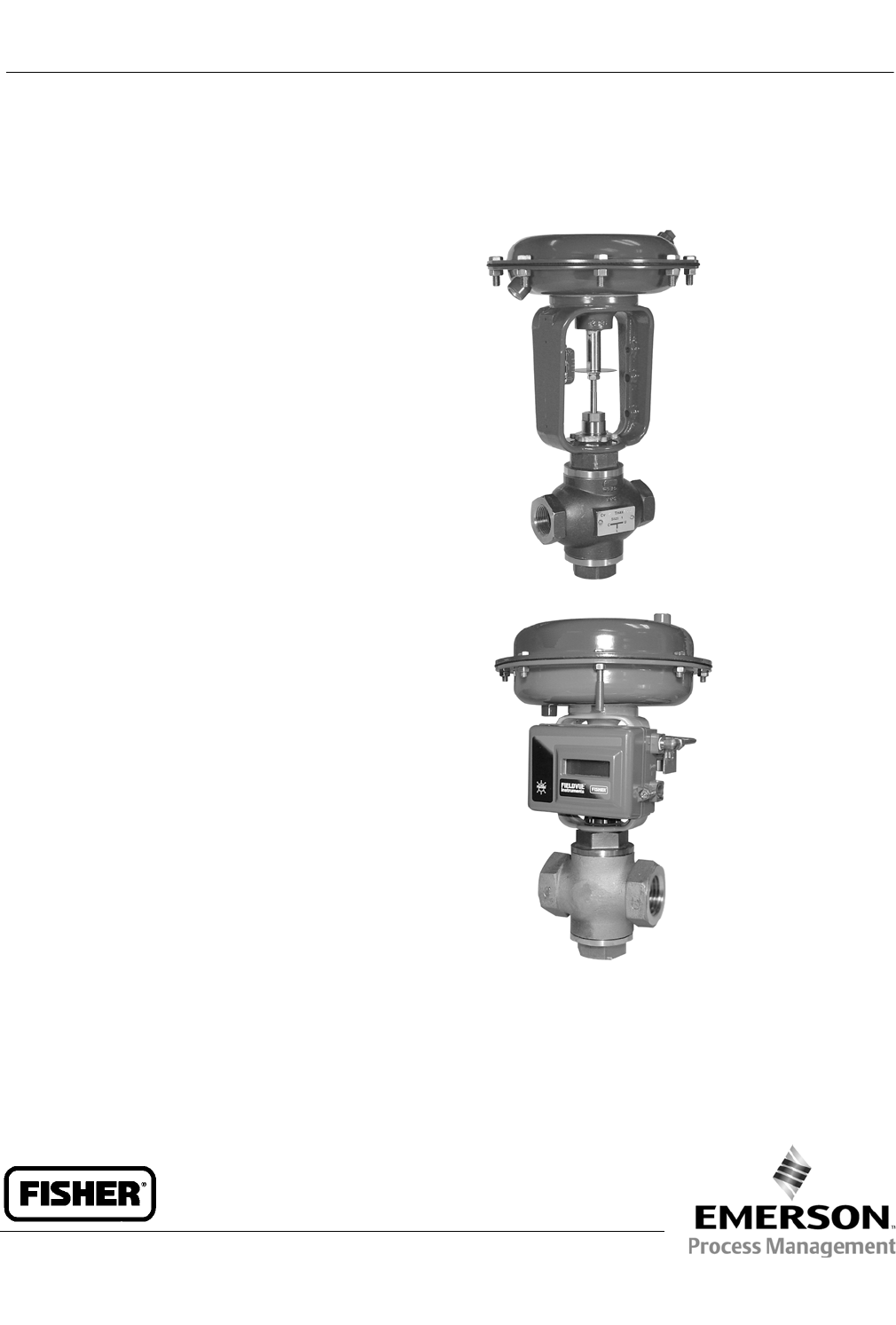
Baumann™ 24003 3-Way Bronze or Stainless
Steel Control Valve
The Baumann 24003 3-way control valve is ideally
suited for control of flow and temperature where
mixing or diverting service is required. This 3-way valve
uses a rugged cast bronze or CF8M stainless steel body
with S31600 austenitic stainless steel trim for
extended service life.
Features
Compactandlightweightdesign reduces installed
piping costs.
Optional ENVIRO-SEALtpacking system to meet
critical emission control requirements; suitable for
use in light duty chemical service (not for use in
corrosive service). This option is available in the
stainless steel version only.
High quality S31600 austenitic stainless steel trim
materials.
Dual plug and stem guiding provides increased
stability during plug travel.
Multiple trim capacity reductions available to meet
changing processrequirements.
Epoxy powder-coated actuator with stainless steel
fasteners for corrosion resistance.
Multi-spring, field-reversible actuator with reduced
deadband, permits direct operation from remote
signal devices.
Actuator and yoke can be removed from the valve
assembly while maintaining packing integrity.
FisherrFIELDVUEtdigital valve controllers available
for remote calibration and diagnostics in facilities
utilizing the PlantWebtarchitecture.
W9764
Stainless Steel 3-Way Valve with Baumann 32 Actuator
W9765
Bronze 3-Way Valve with Baumann 54 Actuator and
FIELDVUE DVC2000 Digital Valve Controller
24003 Valve
D103329X012
Product Bulletin
52.1:243WY
November 2012
24003 Valve
D103329X012
Product Bulletin
52.1:243WY
November 2012
2
Table 1. Flow Direction(1)
Service Inlet Outlet
Diverting CUandL
Mixing UandL C
1. C = Common port, U = Upper port, L = Lower port
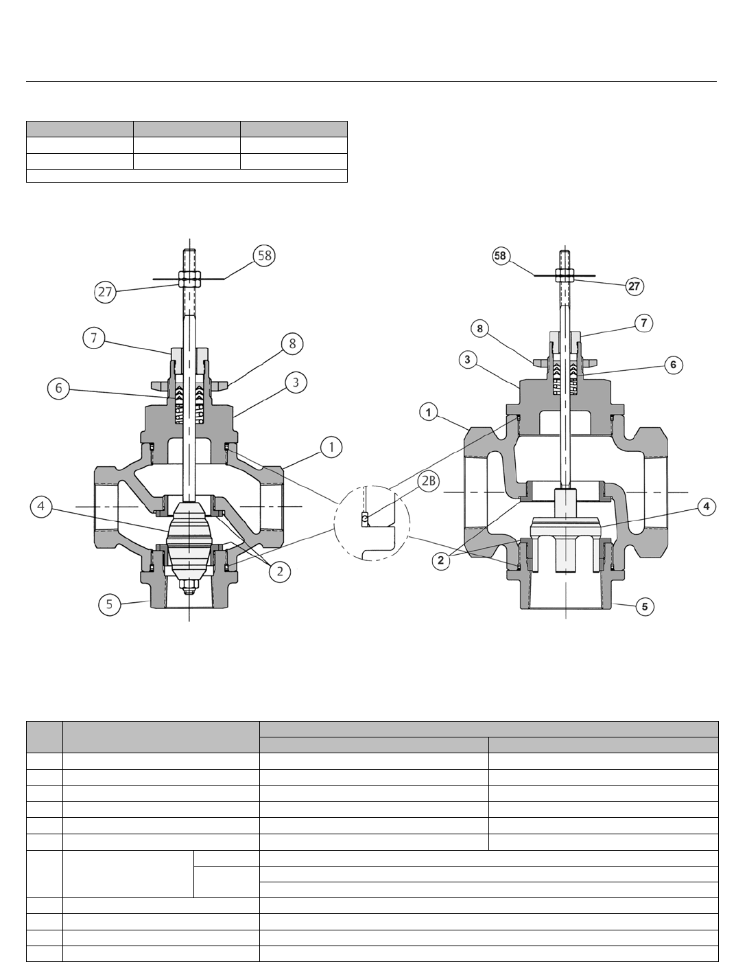
Figure 1. Baumann 24000F Valve Body with Standard Bonnet and NPS 1 Integral Seat
E1281 NPS 1/2 and 1 NPS 1-1/2 and 2
O-RING USED IN
STAINLESS STEEL VALVE
ASSEMBLY ONLY
Table 2. Materials of Construction
KEY
NO. DESCRIPTION MATERIAL
Bronze Stainless Steel
1Valve Body Bronze ASTM B62 ASTM A351 CF8M
2 Seat Rings ASTM A276 S31600 Condition A ASTM A276 S31600 Condition A
2B O-Ring N/A TFE/P (tetrafluoroethylene/propylene)
3Bonnet Bronze ASTM B62 ASTM A351 CF8M
4Plug & Stem Assembly ASTM A276 S31600 Condition A ASTM A276 S31600 Condition A
5Bottom Port Bronze ASTM B62 ASTM A351 CF8M
6Packing
Standard PTFE (Polytetrafluoroethylene) / PTFE, 25% carbon filled
Optional Molded Graphite Ribbon (Flexible Graphite)
ENVIRO-SEAL (Stainless Steel ONLY)
7Packing Follower ASTM A276 S31600 Condition A Stainless Steel
8Drive Nut (Yoke) ASTM A194 S30400 Gr. 8
27 Locknuts Stainless Steel (18-8 SST)
58 Travel Indicator ASTM A240 S30400
24003 Valve
D103329X012
Product Bulletin
52.1:243WY
November 2012
3
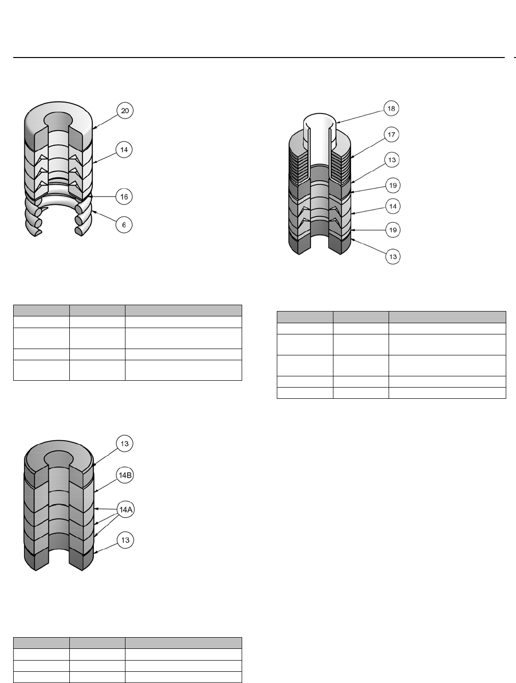
Figure 2. Standard Spring-Loaded PTFE V-Ring
Packing Kit
E1240
Table 3. Standard Spring-Loaded PTFE V-Ring
Packing Kit
Key Number Description Material
6Spring ASTM A313 S30200
14 Packing Set PTFE (Polytetrafluoroethylene) /
PTFE, 25% carbon filled
16 Washer ASTM A240 S31600
20 Spacer J-2000
(filled-Polytetrafluoroethylene)
Figure 3. Molded Graphite (Flexible Graphite)
Packing Kit (Optional)
E1241
Table 4. Molded Graphite (Flexible Graphite)
Packing Kit (Optional)
Key Number Description Material
13 Bushings Carbon-Graphite
14A Packing Rings Graphite
14B Packing Ring Graphite
Figure 4. ENVIRO-SEAL Packing Kit (Optional for
Stainless Steel Only)
E1248
Table 5. ENVIRO-SEAL Packing Kit (Optional for
Stainless Steel Only)
Key Number Description Material
13 Bushing Carbon-Graphite
14 Packing Set PTFE (Polytetrafluoroethylene) /
PTFE, 25% carbon filled
17 Belleville
Spring
N06600 Nickel Alloy (ASTM B637
N07718, 40 HRC max)
18 Bushing PEEK (polyetheretherketone)
19 Washer Modified PTFE
Special ENVIRO-SEAL
Packing Note
The ENVIRO-SEAL PTFE packing system is suitable for
100 ppm environmental applications on services up to
51.7 barg (750 psig) and process temperatures
ranging from -46 to 232_C(-50to450_F).
For non-environmental applications, this packing
system offers excellent performance at the same
temperature range up to the maximum valve working
pressure.
Temperature limits apply to packing arrangements
only. Complete valve assembly temperature limits may
differ, refer to appropriate pressure/temperature
ratings.
(Reference Fisher Packing Selection Guidelines for
Sliding-Stem Valves,Bulletin 59.1:062,
D101986X012).
24003 Valve
D103329X012
Product Bulletin
52.1:243WY
November 2012
4
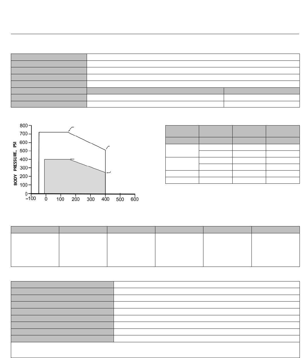
Table 6. Technical Specifications
NOMINAL PIPE SIZE NPS 1/2, 1, 1-1/2, and 2
END CONNECTIONS Screwed NPT
SEAT PLUG SEALING Metal-to-Metal
CHARACTERISTIC Linear
SEAT LEAKAGE Class III
VALVE BODY MATERIAL Bronze Stainless Steel
PRESSURE RATING 400 psi @ 150_F / 250 psi @ 400_F720 psi @ 150_F / 515 psi @ 400_F
TEMPERATURE LIMITS -20 to 400_F-20 to 450_F
Figure 5. Valve Body and Temperature Limits
E1282 OPERATING TEMPERATURE _F
720 psi @ 150_F
515 psi @ 400_F
250 psi @ 400_F
400 psi @ 150_F
CF8M VALVE BODY
ACCEPTABLE OPERATING LIMITS
BRONZE VALVE BODY
ACCEPTABLE OPERATING
LIMITS
Table 7. Maximum Cv Values at 100% Plug Opening
(Kv = 0.86 x Cv)
VALVE SIZE ORIFICE
DIAMETER PLUG TRAVEL RATED
VALUES
NPS inches inches CV
1/2 0.626 0.56 1, 2
0.876 0.56 4
10.876 0.56 4
1.126 0.56 10
1-1/2 1.676 0.75 20
22.126 0.75 40
Table 8. Maximum Cv Values
Valve Series CVRating FLFdXTKC
688
1
2
4
10
20
40
0.9 0.46 0.68 0.73
Table 9. Actuator Specifications
TYPE(1) 32, 54, 70 Multi-Spring Diaphragm (Single Acting)
DIAPHRAGM AREA 210, 350, 450 cm2/ 32, 54, 70 in2
AIR FAILURE 32 and 54 Fails Open or Closed (Field Reversible) / 70 Fails Closed ONLY
TRAVEL(2) 14.2 or 19.1 mm / 0.56 or 0.75 inches
AMBIENT TEMPERATURE RANGE -29_Cto71_C/-20_F to 160_F
MAXIMUM AIR PRESSURE 2.41 barg / 35 psig
DIAPHRAGM MATERIAL(3) NBR (Nitrile) / TPES (Polyester Thermoplastic)
SPRING CASES Steel, Powder Epoxy-Coated with Stainless Steel Fasteners
YOKE Ductile Iron, Powder Epoxy-Coated
1. Electric actuators available. Refer to bulletins 52.1:ECV (D103347X012) and 52.1:NVACT (D103326X012).
2. Dual travel stops are available on Baumann 32 and 54 actuators. These are not field reversible.
3. Optional reinforced VMQ (Silicone) diaphragm with FKM (Fluorocarbon) O-ring actuator stem seal for high temperature conditions (-29_Cto121_C/-20_F to 250_F) is available with
Baumann 32 and 54 actuators ONLY.

24003 Valve
D103329X012
Product Bulletin
52.1:243WY
November 2012
5
Table 10. Allowable Pressure Drops (psi) - Mixing (Combining) Service
ORIFIC
DIAMETER
(inch)
NOMINAL
PLUG TRAVEL
(inch)(1)
ACTUATOR
TYPE
BENCH
RANGE (psi)
ALLOWABLE PRESSURE DROP
PORT L FAILS CLOSED (PSI) BENCH
RANGE (psi)
ALLOWABLE PRESSURE DROP
PORT L FAILS OPEN (PSI)
3-15 psi
Signal to
Actuator
With Positioner
20 psig Air
Supply
3-15 psi
Signal to
Actuator
With Positioner
20 psig Air
Supply
0.626 0.56
32 5-13 112 225 3-11 281 563
7-15 225 337 5-13 112 394
54 7-14 375 563 3-10 469 720
9-15 563 720 3-13 187 656
0.876 0.56
32 5-13 60 121 3-11 151 303
7-15 121 259 5-13 60 212
54 7-14 202 303 3-10 252 505
9-16 303 404 3-13 101 353
1.126 0.56
32 5-13 37 75 3-11 94 189
7-15 75 113 5-13 37 132
54 7-14 126 189 3-10 157 315
9-16 189 252 3-13 63 220
70 8-15 220 309 --- --- ---
1.676 0.75 54 5-15 29 58 3-10 73 147
7-13 58 88 3-13 29 102
70 7-15 82 123 --- --- ---
2.126 0.75
54 3-10 --- --- 3-10 46 93
7-13 37 55 3-13 18 65
70 7-15 52 78 --- --- ---
10-15 91 117 --- --- ---
1. Use Baumann 54 or larger actuator with molded graphite ribbon or ENVIRO-SEAL packing systems.
Table 11. Allowable Pressure Drops (psi) - Diverting (Diverging) Service
ORIFIC
DIAMETER
(inch)
NOMINAL
PLUG TRAVEL
(inch)(1)
ACTUATOR
TYPE
BENCH
RANGE (psi)
ALLOWABLE PRESSURE DROP
PORT L FAILS CLOSED (PSI) BENCH
RANGE (psi)
ALLOWABLE PRESSURE DROP
PORT L FAILS OPEN (PSI)
3-15 psi
Signal to
Actuator
With Positioner
20 psig Air
Supply
3-15 psi
Signal to
Actuator
With Positioner
20 psig Air
Supply
0.626 0.56
32 5-13 80 160 3-11 201 402
7-15 160 241 5-13 80 281
54 7-14 268 402 3-10 335 670
9-15 402 670 3-13 134 469
0.876 0.56
32 5-13 43 86 3-11 108 216
7-15 86 185 5-13 43 151
54 7-14 144 216 3-10 180 360
9-16 216 288 3-13 72 252
1.126 0.56
32 5-13 27 54 3-11 67 135
7-15 54 81 5-13 27 94
54 7-14 90 135 3-10 112 225
9-16 135 180 3-13 45 157
70 8-15 157 220 --- --- ---
1.676 0.75 54 5-15 21 42 3-10 52 105
7-13 42 63 3-13 21 73
70 7-15 59 88 --- --- ---
2.126 0.75
54 3-10 --- --- 3-10 33 66
7-13 26 39 3-13 13 46
70 7-15 37 55 --- --- ---
10-15 65 83 --- --- ---
1. Use Baumann 54 or larger actuator with molded graphite ribbon or ENVIRO-SEAL packing systems.
24003 Valve
D103329X012
Product Bulletin
52.1:243WY
November 2012
6
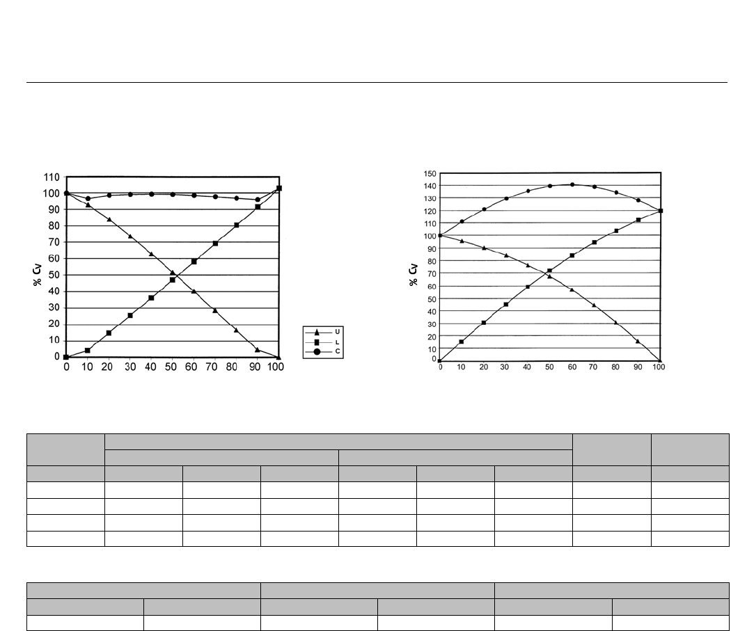
Figure 6. Mixing Service Flow Characteristics
E1283
% TRAVEL
FLOW INTO PORTS U AND L
PERCENTAGE OF MAXIMUM RATED Cv
Figure 7. Diverting Service Flow Characteristics
%TRAVEL
FLOW INTO PORT C
PERCENTAGE OF MAXIMUM RATED Cv
E1284
Table12.ValveBodyDimensionsandWeights:NPTValveBodiesOnly
VALVE SIZE VALVE BODY MATERIAL TRAVEL WEIGHT
BRONZE, NPT STAINLESS STEEL, NPT (A)
NPS A B C1 A B C1 Inches lbs
1/2 4.88 2.75 2.75 5.0 2.75 2.75 0.56 8
14.88 2.75 2.75 5.0 2.75 2.75 0.56 8
1-1/2 5.75 3.81 3.31 6.1 3.38 3.31 0.75 15
26.50 4.0 3.6 6.50 3.75 3.6 0.75 20
Table 13. Actuator Weights
BAUMANN 32 ACTUATOR BAUMANN 54 ACTUATOR BAUMANN 70 ACTUATOR
kg lbs kg lbs kg lbs
4.5 10 11.3 25 15.4 34
24003 Valve
D103329X012
Product Bulletin
52.1:243WY
November 2012
7
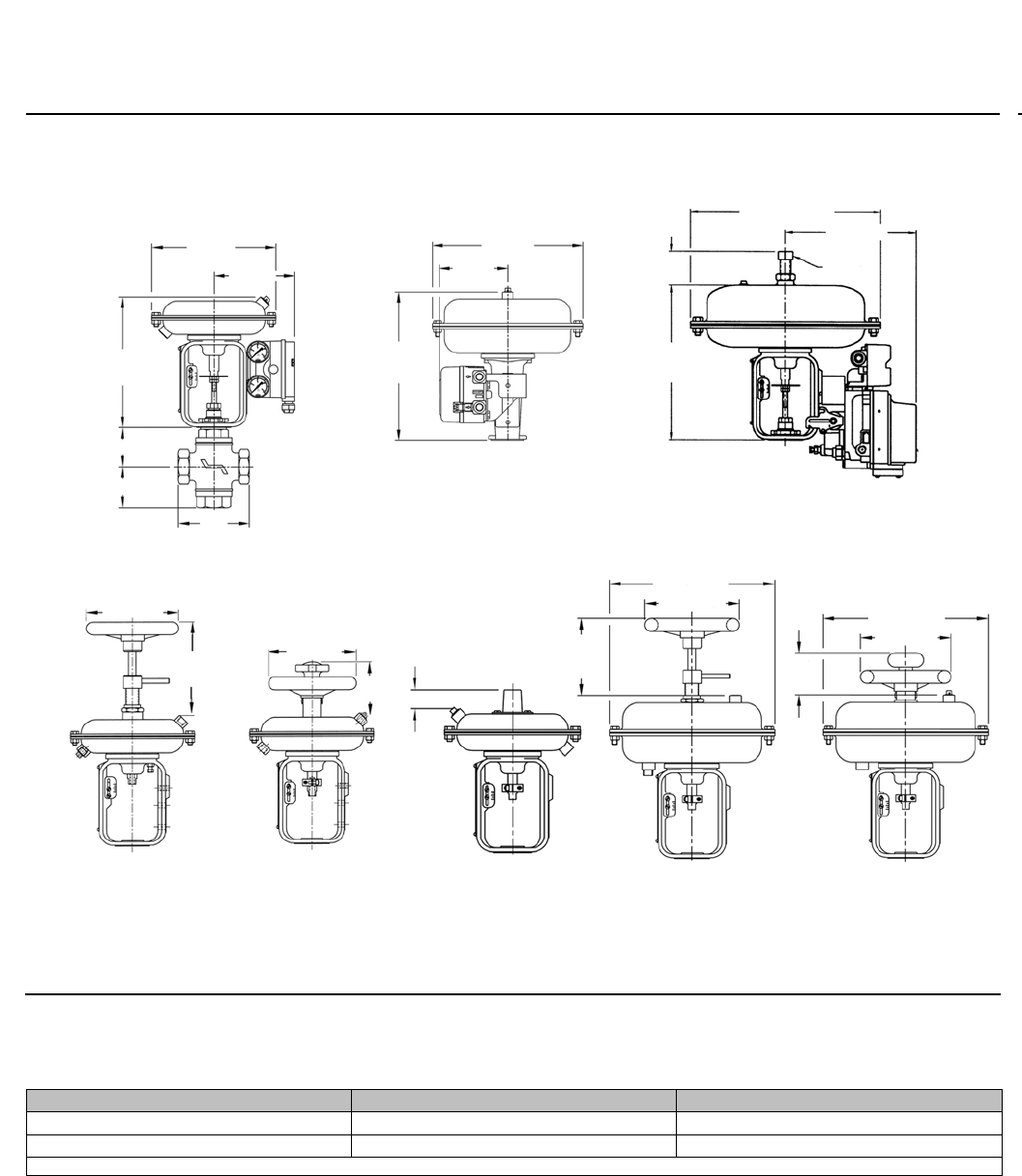
Figure 8. Dimensional Drawings
Note: Actuator removal requires 115 mm (4.5 inches) vertical clearance.
216
(48.5)
279
(411.0)
333 (413.1)
141
(5.5)
127
(5.0)
276
(10.9)
60
(2.4)
271
(10.7)
229
(9.0)
E1285
229
(9.0)
24000 3-WAY WITH BAUMANN 32
ACTUATOR AND 3660/3661 POSITIONER
BAUMANN 54 ATO/FAIL
CLOSED ACTUATOR w/
HANDWHEEL
BAUMANN 70 ACTUATOR w/
FIELDVUE DVC6010 DIGITAL
VALVE CONTROLLER
BAUMANN 32 ATC/
FAIL OPEN ACTUATOR
WITH HANDWHEEL
BAUMANN 54 ATC /
FAIL OPEN ACTUATOR
WITH HANDWHEEL
160
(46.3)
163
(6.4)
160 (46.3)
130 (5.1)
MAX 71 (2.8)
MAX
94
(3.7)
279 (411.0)
279 (411.0)
152
(46.0)
BAUMANN 54 ACTUATOR
w/ FIELDVUE DVC2000
DIGITAL VALVE
CONTROLLER
BAUMANN 32 ATO/
FAIL CLOSED
ACTUATOR WITH
HANDWHEEL
31 (1.24)
152 (46.0)
BAUMANN 32
ACTUATOR WITH
ADJUSTABLE OPEN/
CLOSE DUAL TRAVEL
STOPS
mm
(inch)
C1
B
A
C
L
U
3/4 INCH
SQUARE
Table 14. Application Port(1)
Service Inlet Outlet
Diverting CUandL
Mixing UandL C
1. C = Common port, U = Upper port, L = Lower port
24003 Valve
D103329X012
Product Bulletin
52.1:243WY
November 2012
8
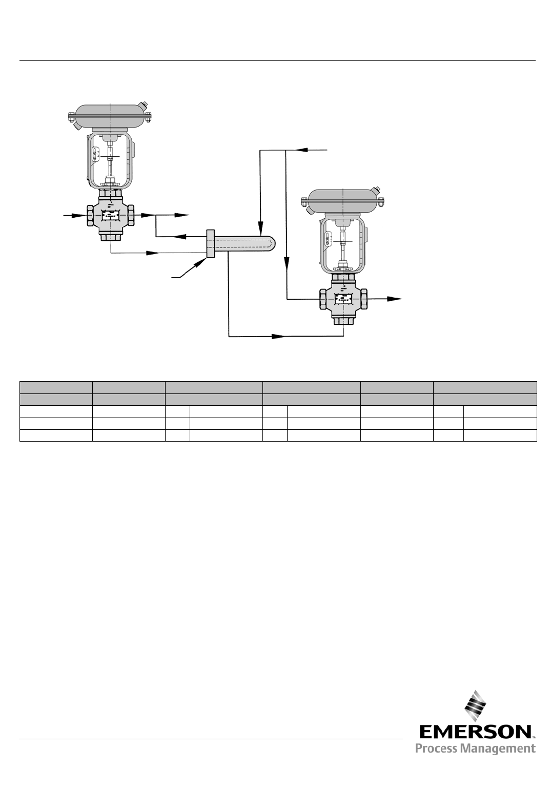
Figure 9. Mixing and Diverting Applications
C
U
L
L
U
C
E1286
DIVERTING
VALVE
COOL
WATER
TEMPERED
WATER
HEAT EXCHANGER
HEATING WATER
MIXING VALVE
RETURN
Table 15. Model Numbering System
24 3
Actuator Type Valve Body Series Service Port “L” Fails 3-Way Valve Body Material
32 24 DDiverting 1Closed 3--- Bronze
54 MMixing 2Open SStainless Steel
70
Emerson Process Management
Marshalltown, Iowa 50158 USA
Sorocaba, 18087 Brazil
Chatham, Kent ME4 4QZ UK
Dubai, United Arab Emirates
Singapore 128461 Singapore
www.Fisher.com
The contents of this publication are presented for informational purposes only, and while every effort has been made to ensure their accuracy, they arenot
to be construed as warranties or guarantees, express or implied, regarding the products or services described herein or their use or applicability. All sales are
governed by our terms and conditions, which are available upon request. We reserve the right to modify or improve the designs or specifications of such
products at any time without notice.
E2009, 2012 Fisher Controls International LLC. All rights reserved.
Baumann, ENVIRO-SEAL, Fisher, FIELDVUE, and PlantWeb are marks owned by one of the companies in the Emerson Process Management business unit of
Emerson Electric Co. Emerson Process Management, Emerson, and the Emerson logo are trademarks and service marks of Emerson Electric Co. All other
marks are the property of their respective owners.
Neither Emerson, Emerson Process Management, nor any of their affiliated entities assumes responsibility for the selection, use or maintenance
of any product. Responsibility for proper selection, use, and maintenance of any product remains solely with the purchaser and end user.
