Emerson Fisher Easy E Ed User Guide
2015-03-30
: Emerson Emerson-Fisher-Easy-E-Ed-User-Guide-680737 emerson-fisher-easy-e-ed-user-guide-680737 emerson pdf
Open the PDF directly: View PDF ![]() .
.
Page Count: 28
www.Fisher.com
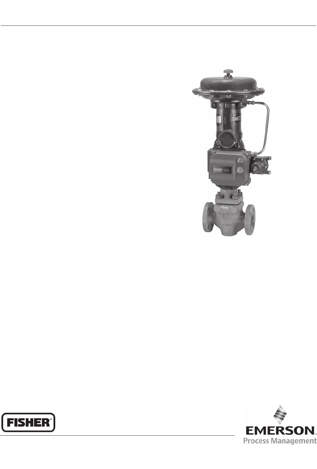
Fisherr easy-et Control Valves
W7957
S Valves for general, erosive, cavitating, or noisy applications
S DN 25 to 300 and NPS 1/2 to 24 sizes
S Choice of balanced or unbalanced trim and metal or soft seats
S Temperatures to 538_C
S Pressures to PN 160 and CL900
S ENVIRO-SEALt packing systems are available to assist in
compliance with environmental emissions requirements
S FIELDVUEt digital valve controllers offer digital control and remote
diagnostics. The traditional proven line of Fisher positioners,
controllers, transmitters, and switches also is available.
Product Flier
PF51.1:E
D102414X012
July 2008 easy-e Valves
easy-e Valves
Product Flier
PF51.1:E
July 2008
2
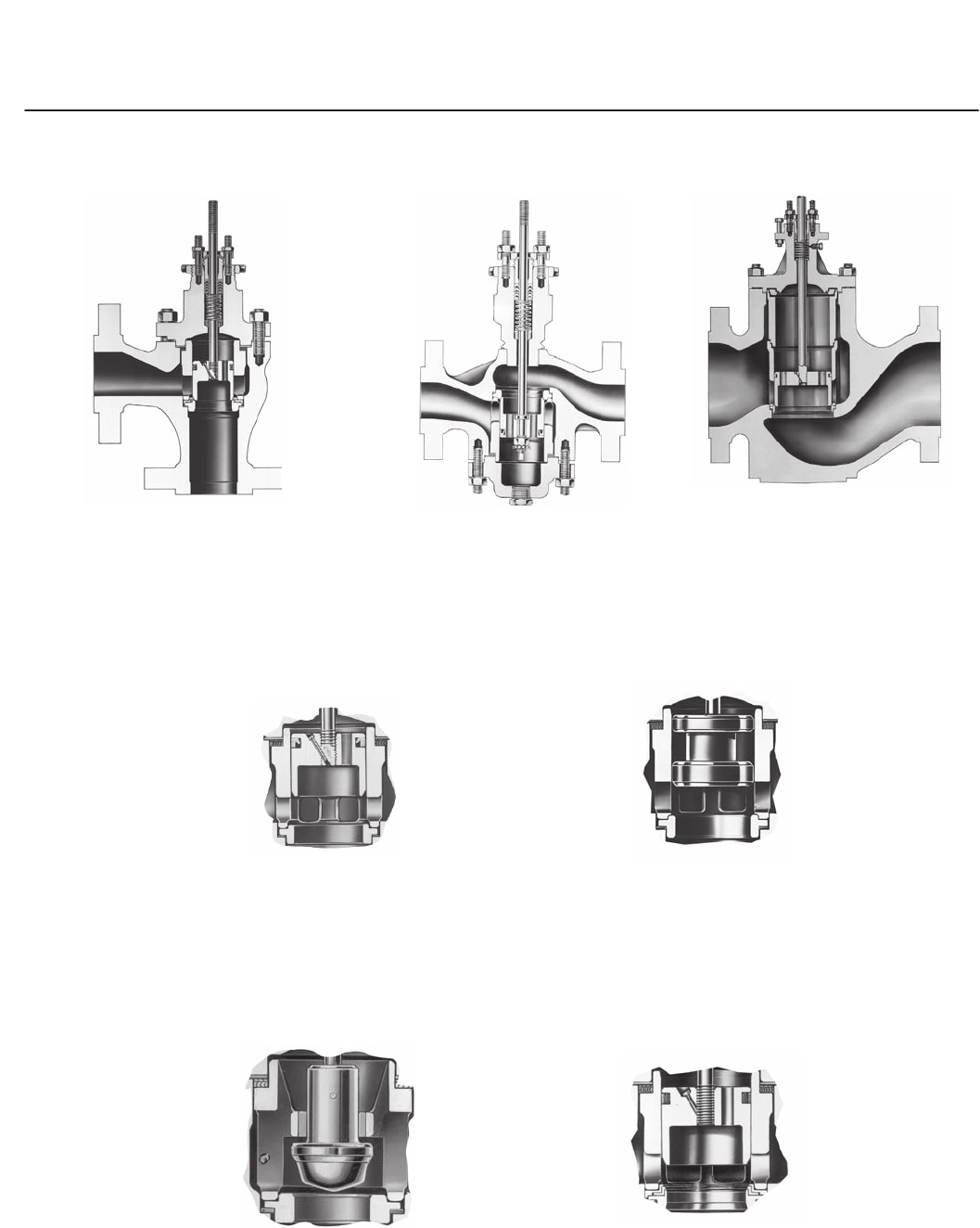
The easy-e Valve Family
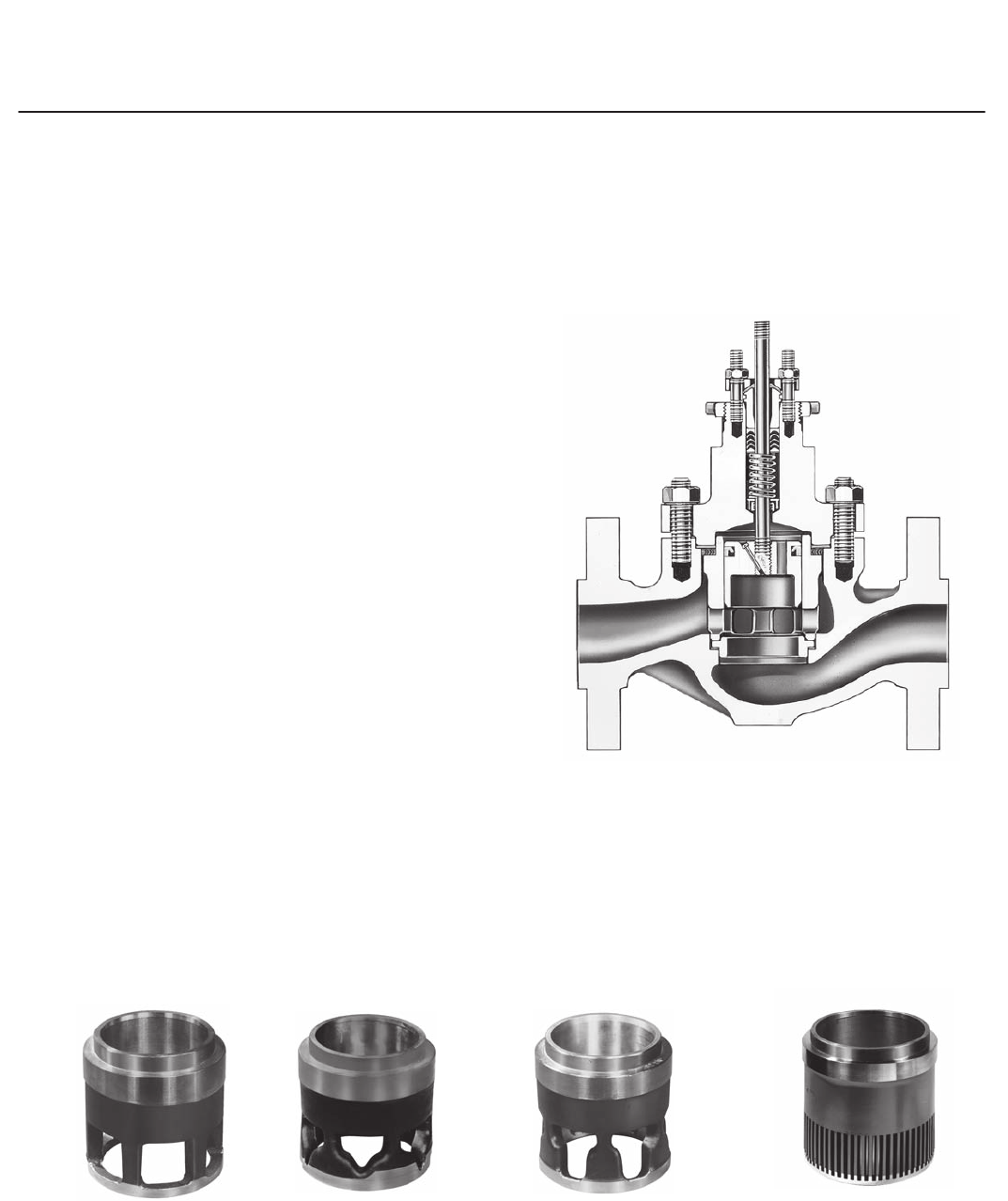
easy-e valves are rugged, single-port globe, angle,
and reverse-acting (push-down-to-open) valves
designed for many varied applications. Although
there are many variations available, internal trim
parts are interchangeable for many different trims,
and maintenance procedures are similar. These
features reduce spare parts inventory and simplify
maintenance training.
Interchangeable Trim Sizes . . . Many easy-e
valves feature interchangeable, restricted-capacity
and full-size trims to meet variable flow demands.
W0451-3
Figure 1. Typical easy-e Globe Valve
Select from Several Flow Characteristics . . . In
most types,
J quick-opening, J linear, and
J equal percentage flow characteristics are
available.
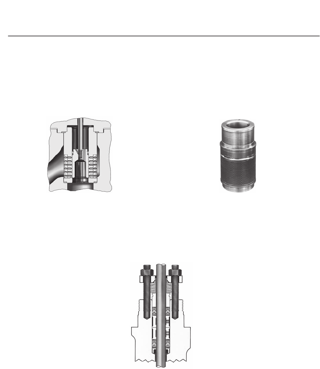
Noise-Attenuating Trim . . . To help reduce
aerodynamic noise in gaseous service, Whisper
Trimt cages are available. To minimize liquid
cavitation damage, Cavitrolt III cages are available.
W0958
Quick Opening Cage
W0957
Equal Percentage Cage
Whisper Trim Cage
for Noise Attenuation
W0959 W0961
Linear Cage
Figure 2. Typical Cages
easy-e Valves
Product Flier
PF51.1:E
July 2008
3
The easy-e Valve Family (Continued)
Materials for Sour Service . . . Materials and
manufacturing procedures for compatibility with
NACE MR0103, and MR0175/ISO 15156 are
available.
W6962
Cavitrol III Trim for Control of Liquid Cavitation
(Typical FL Coefficients for Two- or Three-Stage
Trim is 0.98)
W2629/IL
Whisper Trim III Cage for
Reduction of Noise in
Gas, Steam, and Vapor Applications
Figure 3. Typical Trims
Protection Against Process Fluid Emissions . . .
Optional ENVIRO-SEAL packing systems provide an
improved stem seal to help prevent the loss of
valuable or hazardous process fluids. These
live-loaded systems provide long packing life and
reliability.
W5803-1*
PTFE ENVIRO-SEAL Packing System
Figure 4. ENVIRO-SEAL Packing
easy-e Valves
Product Flier
PF51.1:E
July 2008
4
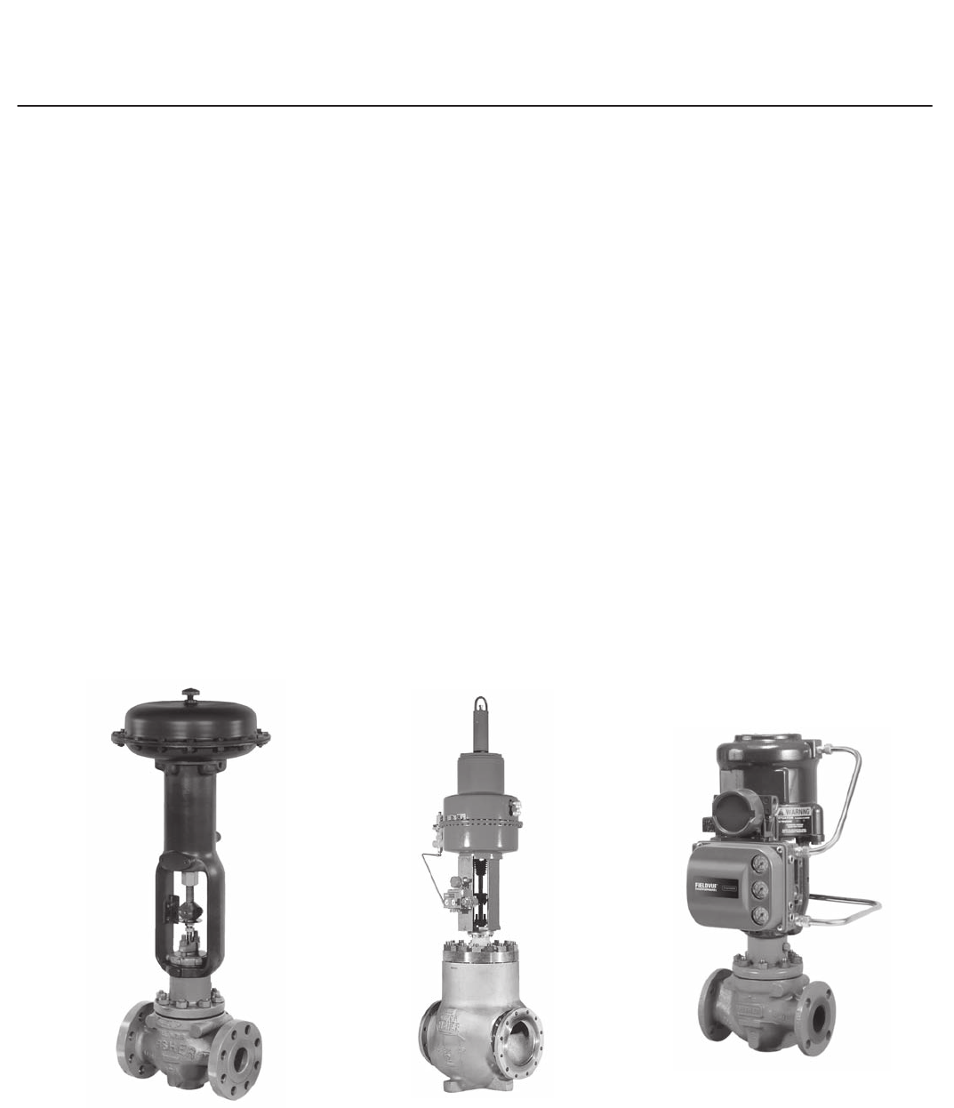
Actuators
657 and 667 Pneumatic Diaphragm Actuators . . .
Rugged, heavy-duty spring-return actuators. These
actuators are available with a variety of instrument
accessories, handwheels, and adjustable travel
stops. They can be used for on-off or throttling
operation with or without a valve positioner.
3025 Diaphragm Actuators . . . Spring-opposed
diaphragm actuators. Suitable for travels up to 200
mm (8 inches). Specified as either direct or reverse
acting, actuator action can be easily changed on site
without need of additional parts. They can be used
for on-off or throttling operation of automatic control
valves.
Piston Actuators . . . J585C size 25 through 130
actuators for high thrust requirements. J585CLS
(long stroke) piston actuators feature high thrust and
long travels for very large valves.
Accessories
FIELDVUE Digital Valve Controller . . . The
controller is available mounted on actuators.
Positioners and Transducers . . . Pneumatic
positioners and electro-pneumatic positioners and
transducers can be provided with these valves.
Position Transducers, Solenoid Valves, Limit
Switches, and Controllers . . . Also available.
W1916-2
657 or 667 Actuator
W9131-1
585C Actuator
3025 Actuator
W9088
Figure 5. Typical Actuators

easy-e Valves
Product Flier
PF51.1:E
July 2008
5
Selecting easy-e Products
Only a few of the more commonly selected product materials, sizes,
options, and accessories are covered in this flier.
Contact your nearest sales office (refer to the back cover) for assistance
in selecting and sizing these products. More detailed specifications are
available on request.
Selecting Valve Components
Valve Trim and Body Style 6.................................
End Connections and Valve Body Materials 8..................
Valve Plug, Seat, Ring, and Cage (Trim) Materials 9.............
Bonnets 9.................................................
Other Valve Parts 10........................................
Selecting an Actuator
657 and 667 Pneumatic Diaphragm Actuators 11...............
3025 Diaphragm Actuators 12................................
Selecting Accessories
FIELDVUE Digital Valve Controller 13.........................
Valve Positioners 15........................................
Other Accessories 16.......................................
Reference Information
Trim Material Pressure/Temperature Capabilities 17.............
Flow Coefficients 19........................................
Conversion of Sizing Coefficients 20..........................
Actuator Size Selection 22...................................
Typical Valve and Actuator Weight 24.........................
Typical Dimensions 24......................................
Ordering Information 26.....................................
Sales Offices NO TAG.......................................

easy-e Valves
Product Flier
PF51.1:E
July 2008
6
Valve Trim and Body Style
Letter Designations
Used in this Table %
E: Valve design series
T, D, S, and Z: Trim type
U: Large size
W. Expanded ends
N: Long travel
A: Angle valve style
R: Reverse acting (push down
to open)
Application Trim Type Fisher Trim
Designation Body Style Fisher Valve
Body Valve Size Ratings Standard
Shutoff Class
Stringent
shutoff with
process
temperatures
to 204_C
Balanced,
cage-guided
with elastomer
cage-plug seal
and soft or
metal seats
T
Globe ET DN 25 - 200
NPS 1 - 8 PN 10 - 100
CL125 - 600
Soft seat: V
Metal seat: IV
(standard) or V
(optional)
Reverse acting
(push-down-to-open) ETR DN 25 - 100
NPS 1 - 4
Angle EAT DN 25 - 150
NPS 1 - 6
PN 10 - 100
CL150 - 600
Globe with expanded
end connections EWT
DN 100 x 50(1)
(NPS 4 x 2)
through
NPS 24 x 20
PN 25 - 160
CL300 - 900
Globe with expanded
end connections and
long travel for
noise-attenuating trim
EWNT (metal
seats only)
DN 200 x 150 and
DN 300 x 200
NPS 8 x 6 and 12 x
8
PN 25 - 160
CL300 - 900 IV
Large globe with long
travel EUT NPS 12, 16, 20 CL150 - 600 Soft seat: V
Metal seat: IV
General
applications for
process
temperatures
to 427_C
Balanced,
cage-guided
with graphite
cage-plug seal
and metal
seats
D
Globe ED DN 25 - 200
NPS 1 - 8 PN 10 - 100
CL125 - 600 II
Reverse acting
(push-down-to-open) EDR DN 25 - 100
NPS 1 - 4
Angle EAD DN 25 - 150
NPS 1 - 6
PN 10 - 100
CL150 - 600
Globe with expanded
end connections EWD
DN 100 x 50
(NPS 4 x 2)
through NPS 24 x
20
PN 25 - 160
CL300 - 900
Through
12 x 8: II
Larger sizes: III
Globe with expanded
end connections and
long travel for
noise-attenuating trim
EWND
DN 200 x 150
through DN 300 x
200 NPS 8 x 6
through
NPS 12 x 8
PN 25 - 160
CL300 - 900 III
Large globe with long
travel EUD NPS 12, 16, 20 CL150 - 600 III
General
applications for
process
temperatures
to 538_C
Unbalanced,
cage-guided
without
cage-plug seal
and with metal
or soft seats
S
Globe ES DN 25 - 200
NPS 1/2 - 8
PN 10 - 100
CL125 - 600
Metal Seat: IV
Soft Seat: VI
Angle EAS DN 25 - 150
NPS 1 - 6
PN 10 - 100
CL150 - 600
Globe with expanded
end connections EWS
DN 100 x 50
through DN 300 x
200
NPS 4 x 2 through
NPS 12 x 8
PN 25 - 160
CL300 - 900
Viscous,
non-lubricating,
or other
hard-to-handle
fluids with
process
temperatures
to 427_C
Unbalanced
cageless,
post-guided
with metal or
soft seals
Z Globe EZ DN 25 - 100
NPS 1/2 - 4
PN 10 - 100
CL125 - 600
Metal Seat: IV
Soft Seat: VI
1. End connection size x nominal trim size.
easy-e Valves
Product Flier
PF51.1:E
July 2008
7
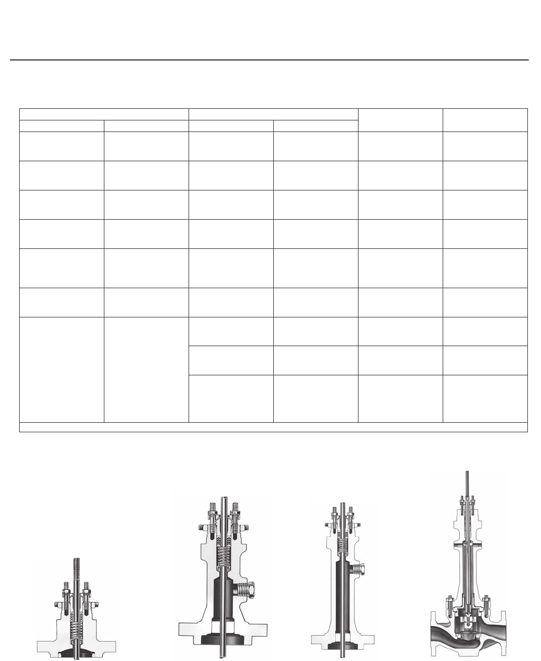
Valve Trim and Body Style (Continued)
W0972-3
Typical Angle Valve
W9509-1
Typical Reverse-Acting Valve
W3318
Valve with Long Travel and
Expanded End Connections
W0451-1
ED Trim
W3421-1
ES Trim
W2966B-1
EZ Trim
W3162-1
ET Trim
easy-e Valves
Product Flier
PF51.1:E
July 2008
8
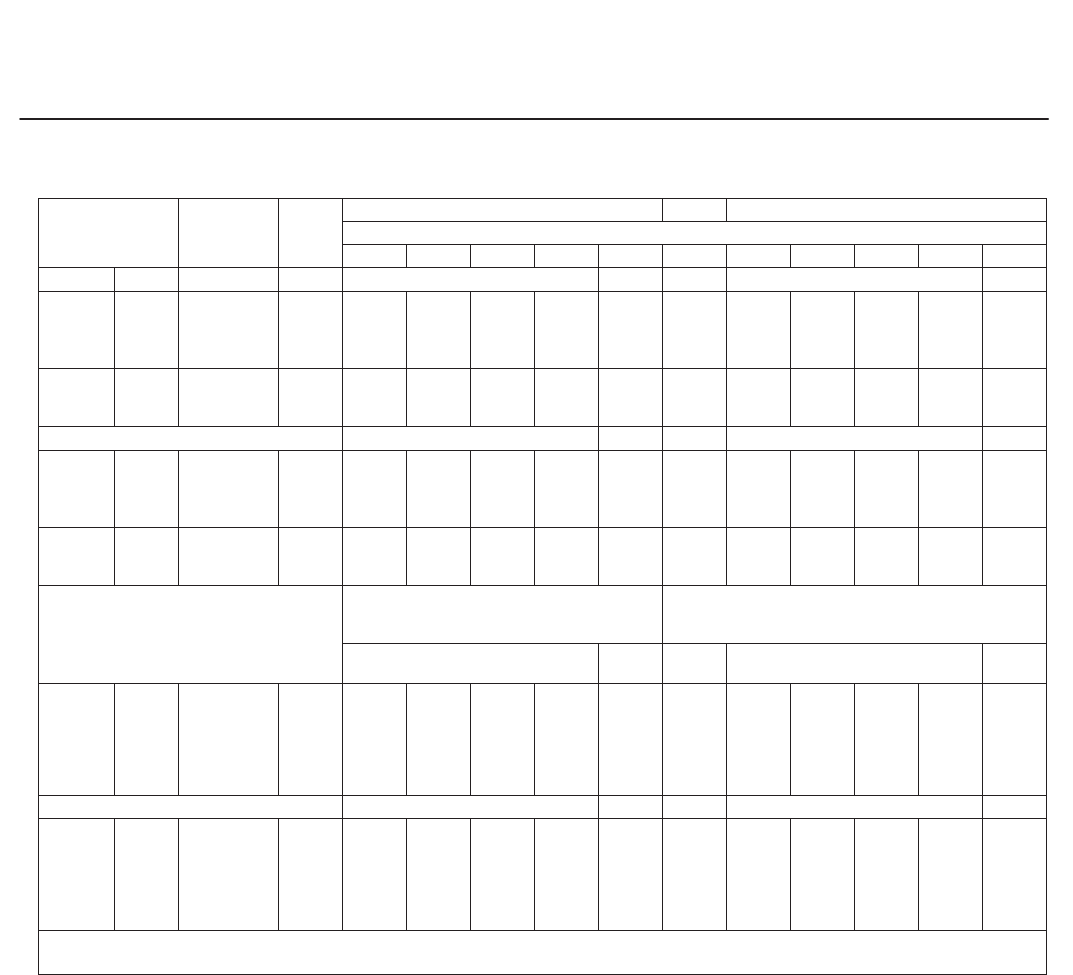
End Connections and Valve Body Materials
END CONNECTIONS VALVE SIZE MATERIALS NOTES
EN ASME DN NPS
- - - NPT internal CL600
body rating - - - 1/2 - 2
WCC steel, CF8M
(316 stainless steel),
and other steel alloys
Not available in angle
valves
PN 10, 16, and 25
raised-face flanged
CL125 flat-face and
250 raised-face
flanged
25 - 200 1 - 8 Cast iron Not available in
NPS 1-1/4
PN 16, 25, 40, 63, and
100 raised-face
flanged
CL150, 300, and 600
raised-face or
ring-type joint flanged
25 - 200 1 - 8
WCC steel, CF8M
(316 stainless steel),
and other steel alloys
Not available in
NPS 1-1/4
PN 16, 25, 40, 63,
100, and 160
raised-face flanged
CL300, 600, or 900
raised-face or
ring-type joint flanged
100 x 50
through
300 x 200
4 x 2(1)
through
12 x 8
WCC steel, CF8M
(316 stainless steel),
and other steel alloys
- - -
- - -
CL150, 300, and 600
raised-face or
ring-type joint flanged
- - -
12 - 24 and
16 x 12
through
24 x 20
WCC steel, CF8M
(316 stainless steel),
and other steel alloys
- - -
- - - Socket weld ends
(CL600 body rating) - - - 1/2 - 2
WCC steel, CF8M
(316 stainless steel),
and other steel alloys
Not available in angle
valves
- - - Buttwelding ends
- - - 1 - 8
WCC steel, CF8M
(316 stainless steel),
and other steel alloys
Not available
in NPS 1-1/4
Available in CL600
- - -
4 x 2
through
12 x 8
WCC steel, CF8M
(316 stainless steel),
and other steel alloys
CL300, 600, or 900
- - -
12 through 24
and
16 x 12
through
24 x 20
WCC steel, CF8M
(316 stainless steel),
and other steel alloys
CL600
1. End connection size x nominal trim size.
Plain Bonnet with Single
PTFE V-Ring Packing
Style 1 Extension Bonnet Style 2 Extension Bonnet ENVIRO-SEAL
Bellows Seal Bonnet
W6733
W0668-2 W0667-2
W5800-2
easy-e Valves
Product Flier
PF51.1:E
July 2008
9
Valve Plug, Seat Ring, and Cage (Trim) Materials
VALVE TYPE BODY MATERIAL SEAT TYPE MATERIALS FISHER TRIM
NUMBER(2) NOTES
Valve Plug Seat Ring Cage
ED, ES, EWD,
EWS through
DN 300 x 200(1)
(NPS 12 x 8
sizes)
Standard for all body
materials except
CF8M (316 stainless
steel)
Metal
S41600 (416
stainless
steel)
hardened to
38 HRC
Depending on size,
S41600 or CA15 (410
stainless steel) both
hardened to 38 HRC
S17400
(17-4PH
stainless
steel)
hardened to
40 HRC
1
Trims with
alloy 6
hardfacing
also are
available. For
optional ES,
EWS soft
seat, use trim
29 or 57
CF8M Metal
S31600 (316
stainless
steel)
S31600
S31600 with
electroless
nickel coating
(ENC)
29
ET, EWT
through DN
300 x 200
(NPS 12 x 8)
Standard for all body
materials except
CF8M (316 stainless
steel)
Soft
S41600 (416
stainless
steel)
hardened to
38 HRC
S31600
S17400
(17-4PH
stainless
steel)
hardened to
40 HRC
57 Trims with
alloy 6
hardfacing
also are
available. For
optional metal
seats, use
trim1 or 29
CF8M Soft S31600 S31600
S31600 or
CF8M with
electroless
nickel coating
(ENC)
29
EZ
Cast iron and steel Metal S41600
hardened
S41600 hardened
seat ring with
CB7Cu-1 (17-4PH
stainless steel) seat
ring retainer
- - - 101
Trims with
alloy 6
hardfacing
also are
available.
CF8M Metal S31600 S31600 with CF8M
seat ring retainer - - - 129 - - -
1. End connection size x nominal trim size.
2. Refer to the following pages for pressure and temperature limits of the trim.
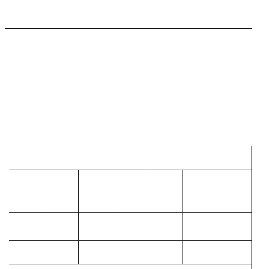
Bonnets
Bonnet Style Valve Type or Size Packing Material In-Body Process
Temperature Range, _CNotes
Plain All types and sizes
PTFE V-Ring -18 to 232
These in-body process
temperatures assume an
ambient temperature of
21_C. When using any
packing at low process
temperatures, an extension
bonnet might be needed to
prevent valve stem frost.
Frost can damage the
packing.
PTFE/composition -18 to 232
Graphite ribbon/filament 18 to maximum limit
shown in other tables
Style 1 extension
Globe and angle only; not
available for EUD, EUT or
16 x 12 or larger
EW
PTFE V-ring
46 to 18 and above 232
PTFE/Composition
Graphite ribbon/filament
Style 2 extension
Globe and angle only; not
available for EUD, EUT,
EWN, or 16 x 12 or larger
EW
PTFE V-ring
101 to 18 and above 232
PTFE/Composition
Graphite ribbon/filament
ENVIRO-SEAL bellows seal
bonnet
Available only on globe and
angle valves through DN
100 and DN 200 x 100
(NPS 4 and 8 x 4)
For exceptional stem
sealing capabilities with
PTFE or graphite standard
packing or with
ENVIRO-SEAL packing
system
Contact your nearest sales
office

easy-e Valves
Product Flier
PF51.1:E
July 2008
10
Other Valve Parts
PART VALVE TYPE
OR SIZE MATERIALS TEMPERATURE
RANGE, _CNOTES
Body-to-bonnet
bolting
All sizes and types
except as listed
below
Use for Body
Material:
Cap Screws, Stud, or
Nut Material - - - - - -
Cast iron Steel SAE GR 5 cap screws 29 to 232
WCC, C5, and WC9
steel
SA-193-B7 steel studs
SA-194-2H steel nuts 29 to 427
Specify lubricated
nuts for
temperatures
greater than 232_C
CF8M
SA-193-B7 steel studs
SA-194-2H steel nuts 48 to 427
SA-193-B8M stainless steel studs
(strain hardened)
SA-194-8M stainless steel nuts
198 to 427
SA-193B8M stainless steel studs
(annealed)
SA-194-8M stainless steel nuts
The lower limit is
198; other valve
parts determine the
upper limit
- - -
Packing (also refer
to the bonnet
selection table)
All types (see notes for exceptions)
PTFE V-ring 40 to 232
- - -
PTFE/composition 73 to 232
Graphite ribbon/filament in
oxidizing service 198 to 371
Graphite ribbon/filament in
non-oxidizing service 198 to 538
ENVIRO-SEAL and HIGH-SEAL
packing systems with PTFE,
duplex, Kalrez, or graphite
packing
Temperature limits vary with pressure and
fugitive emissions standards; contact your
nearest sales office for information
Flat gaskets
EZ S31600 stainless steel / graphite 198 to 593 Limit to 427_C in
oxidizing service
PTFE-coated N04400 73 to 149 - - -
All sizes and types except EZ
S31600/graphite in oxidizing
service 198 to 593 Limit to 427_C in
oxidizing service
PTFE-coated N04400 73 to 149 - - -
Spiral-wound gasket All
N06600 nickel alloy 600 /
graphite (flexible graphite)
standard
198 to 593 - - -
N04400 nickel alloy 73 to 232
Soft seat disc ES, ET, EUT, EWS, EWT, EZ PTFE 73 to 204 - - -
Piston ring for ED
type trim ED and EWD Graphite in oxidizing service 46 to 427 - - -
Graphite in non-oxidizing service 46 to 482 - - -
Seal ring for ET type
trim
ET, EWT (up to
DN 300 x 200 or NPS 12 x 8 sizes)
Carbon-filled PTFE seal ring with
fluorocarbon backup ring 18 to 204
Do not use
fluorocarbon with
ammonia, steam, or
hot water
Carbon-filled PTFE seal ring with
ethylene-propylene backup ring 40 to 232
Do not use
ethylene-propylene
with
petroleum-based
fluids or other
hydrocarbons
Spring-loaded PTFE seal ring
with N07750 spring and stainless
steel backup ring and retaining
ring
73 to 232 - - -
easy-e Valves
Product Flier
PF51.1:E
July 2008
11
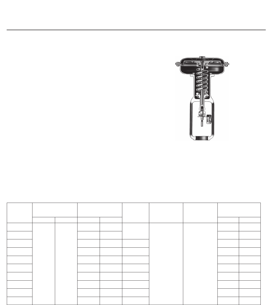
657 and 667 Pneumatic Diaphragm Actuators
These heavy-duty actuators feature spring-return
action and a variety of operation options and
actuator-mounted accessories.
The actuator can be used for on-off or throttling
service, with or without a positioner.
With a push-down-to-close valve, the 657 is air to
close, and the 667 is air to open.
Options . . . J Adjustable travel stop, J
top-mounted handwheel, and J side-mounted
manual actuator.
Specifications . . . Refer to the following table and
the actuator-valve selection tables.
Accessories . . . Refer to the following pages for J
pneumatic and electro-pneumatic valve positioners,
J FIELDVUE digital valve controllers, and other
accessories
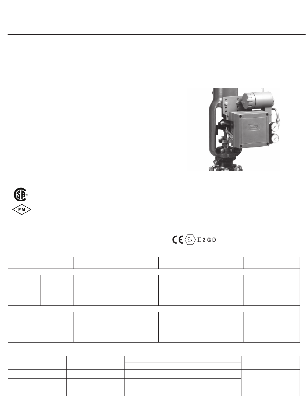
W0363-1
Figure 6. 657 and 667 Actuator
657 and 667 Actuator Specifications
ACTUATOR
SIZE
NOMINAL
OPERATING
PRESSURE RANGES
MAXIMUM CASING
PRESSURE, BAR MAXIMUM
ALLOWABLE
THRUST, N
AMBIENT
TEMPERA-
TURES, _C
MATERIALS
APPROXIMATE
WEIGHT, kg
Bar Psig 657 667 657 667
30
0.2 to 1.0
or
0.4 to 2.0
3 to 15
or
6 to 30
9.6 7.6
10 231
Nitrile:
40 to 82
Silicone:
50 to 149
Diaphragm:
Nitrile (standard)
or
Silicone
(Optional)
Yoke: Cast iron
Diaphragm
Plate: Aluminum,
cast iron, or steel
(depending on
size)
Other Major
Metal Parts: steel
or cast iron with
brass seal
bushing
16 15
34 5.2 6.2 22 22
40 5.2 6.2 12 010 23 23
45 4.1 5.2 25 132 37 41
46 3.4 4.5 33 584 49 55
50 4.1 5.2 25 131 42 43
60 3.4 4.5 30 246 53 55
70 4.5 4.1 39 142 107 115
80 4.1 4.1 63 392 234 284
100 7.9 7.9 200 160 346 544
easy-e Valves
Product Flier
PF51.1:E
July 2008
12
3025 Diaphragm Actuators
These heavy-duty spring-opposed actuators can be
specified as either direct (air-to-close) or reverse
(air-to-open). Actuator action can be easily changed
on site without need of additional parts.
The actuator can be used for on-off or throttling
operation of automatic control valves.
Options . . . J Side-mounted gear handwheel, J
Oversize signal connections.
Specifications . . . Refer to the following table.
Accessories . . . Refer to the following table.
3025 Actuator Specifications
Features
Long travel, up to 200 mm (8 inches)
Style
Spring-opposed pneumatic diaphragm
Typical Maximum Thrust, Newtons (Varies with Operating
Pressure, Spring, and Construction)
Air to Close, Size P900: 76 310
Air to Open, Size P900: 61 150
Accessories
FIELDVUE digital valve controllers, handwheels, transducers,
position transmitters, air relays, volume boosters, switching valves,
lockable valves, limit switches, and solenoid valves are available
for actuator mounting.
AIR TO CLOSE AIR TO OPEN
Figure 7. 3025 Actuator
easy-e Valves
Product Flier
PF51.1:E
July 2008
13
FIELDVUE Digital Valve Controller
FIELDVUE digital valve controllers are
communicating, microprocessor-based controllers
that convert a current signal to a pressure signal to
operate the actuator. Through digital
communications, the controller gives easy access to
actuator-valve information that is critical to operation.
Refer to following tables for FIELDVUE controller
specifications.
AMS ValveLinkt Software . . . AMS ValveLink
Software allows easy access to the information
available from FIELDVUE digital valve controllers.
The software provides diagnostic information such
as dynamic error band and step response on
easy-to-interpret screens. Tests can be run while the
valve is operating, without disrupting the process.
Access to diagnostics is through the 375 Field
Communicator or a personal computer using AMS
ValveLink Software.
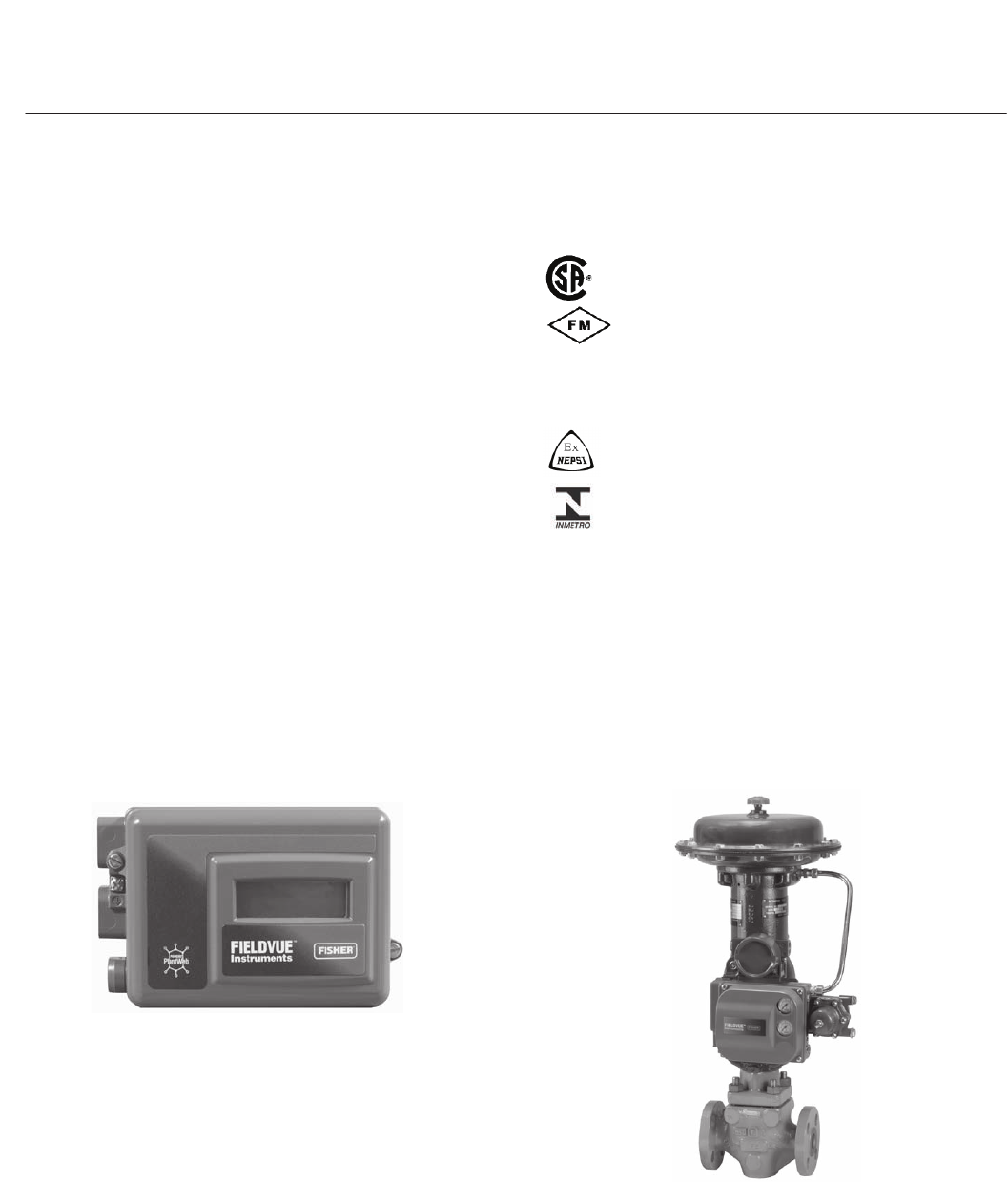
W8755
Figure 8. FIELDVUE DVC2000 Digital Valve Controller
Options (contact your sales office for details on
product specific options) . . . JHARTr,
JFOUNDATIONt fieldbus, Jremote mounting,
Jstainless steel housing, JSafety Instrumented
System (SIS) applications, JNatural gas
applications, JPerformance Diagnostics,
Jextreme temperatures, and Jlow bleed relay.
Approvals Available
Not all approvals are available on all FIELDVUE
products. Contact your sales office for specific
approvals.
Explosion proof, Division 2, Dust-Ignition
proof, Intrinsic Safety, Non-incentive
Explosion proof, Non-incendive,
Dust-Ignition proof, Intrinsic Safety
Flameproof, Type n, Intrinsic Safety
IECEx Flameproof, Type n, Intrinsic Safety
Flameproof, Intrinsic Safety
Flameproof, Intrinsic Safety
DVC2000 Electrical Housing: Designed to meet
IP66 (FM--approval pending for other agencies)
NEMA 4X (approval pending). Contact your sales
office for information on pending approvals.
DVC6000 and DVC6000f Electrical Housing:
Meets NEMA 4X, CSA Type 4X, IEC 60529 IP66
Natural Gas Approved: DVC6000 and DVC6000f
are single-seal approved for use with natural gas.
Contact your sales office for specific agency
approval information.
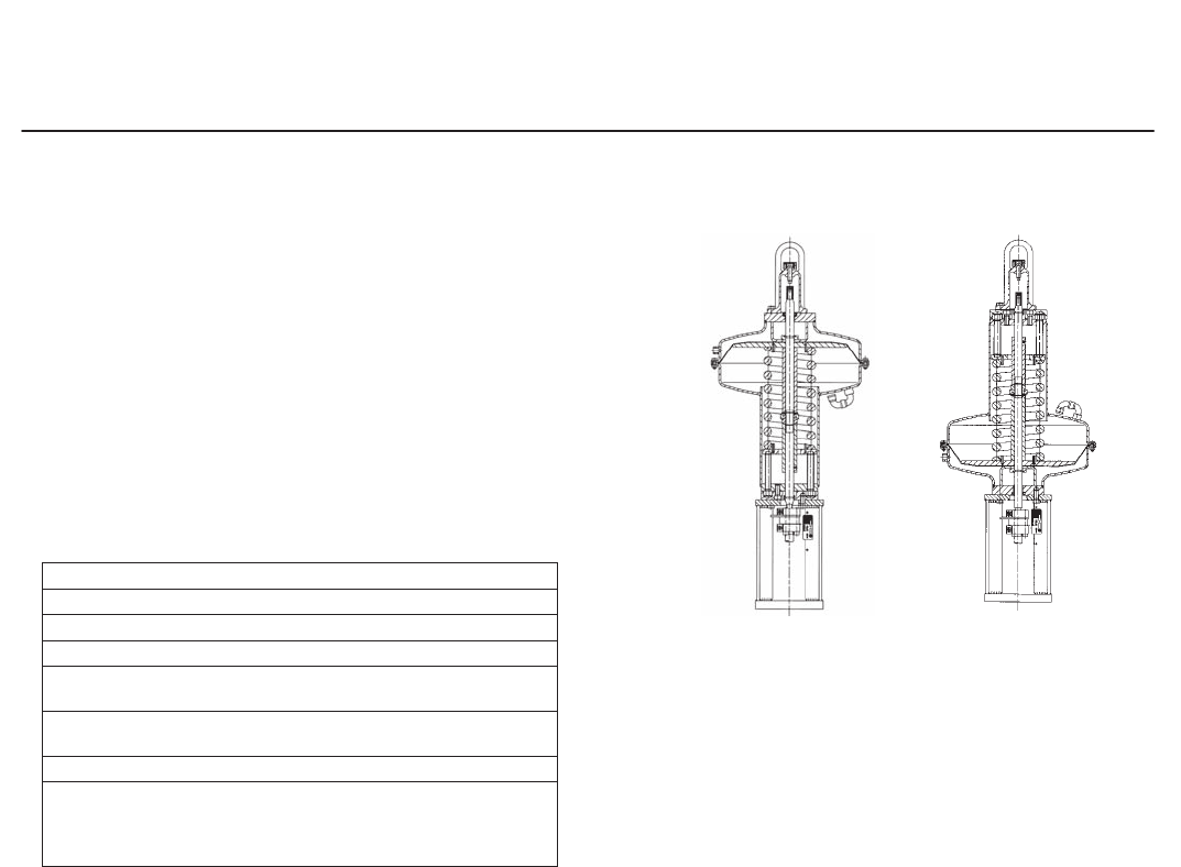
W7957
Figure 9. FIELDVUE DVC6000 Digital Valve Controller on a
657 or 667 Actuator
APPROVED
ATEX

easy-e Valves
Product Flier
PF51.1:E
July 2008
14
FIELDVUE Digital Valve Controller
(Continued)
Digital Valve Controller Electrical Specifications (HART instruments only)
ELECTRICAL INPUT
REVERSE
POLARITY
PROTECTION
Point-to-Point Connection
Multi-Drop
Connection
(DVC6000 Only)
Analog Input
Signal
Minimum
Control
Current
Minimum Current
without
Microprocessor
Restart
Maximum
Voltage
Overcurrent
Protection
Instrument
Power
4 to 20 mA DC
nominal 4.0 mA 3.5 mA 30 VDC
Input circuit limits
current to prevent
internal damage
11 to 30 VDC at
approximately 8 mA
No damage occurs
from reversal of
loop current
Digital Valve Controller Electrical Specifications (FOUNDATION fieldbus Communication only)
COMMUNICATION PROTOCOL
POWER REQUIREMENTS
Voltage Level Maximum
Current
Reverse
Polarity
Protection
Termination
FOUNDATION fieldbus registered device
Physical Layer Type(s):
121—Low-power signaling, bus-powered, Entity Model I.S.
511—Low-power signaling, bus-powered, FISCO I.S.
9 to 32 volts 18 mA Device is not
polarity sensitive
Bus must be properly
terminated per
ISA SP50 guidelines
easy-e Valves
Product Flier
PF51.1:E
July 2008
15
Valve Positioners
3582 and 3582i Valve Positioners (for 657 and 667 Actuators)
The 3582 pneumatic and 3582i electro-pneumatic
valve positioners are accurate, efficient positioners
for use with 657 and 667 actuators.
The field-proven design is fast to respond to input
signal changes and is able to withstand the
vibrations of most plants.
Options . . . J Gauges and J bypass valve for
direct-acting positioners using full input signal range.
Approvals Available
Electrical Classification (Applies to the 3582i)
Intrinsic Safety, Explosion proof, Type n
Dust-Ignition proof, DIV 2,
Intrinsic Safety, Explosion proof, Type n,
Non-incendive, Dust-Ignition proof,
Intrinsic Safety, Type n, Explosion proof
(Gas Atmospheres Only)
Intrinsic Safety, Flameproof, Type n
W5500
Figure 10. 3582 and 3582i Valve Positioners
Hazardous Area Classifications (Applies to the
3582)
3582 Series valve positioners comply with the
requirements of ATEX Group II Category 2 Gas
and Dust
3582 and 3582i Positioner Specifications
Input Signal Supply Pressure Input Bellows
Rating
Operative
Temperature Weight Connections
3582
0.2 to 1.0 or
0.4 to 2.0 bar
3 to 15 or
6 to 30 psig
0.3 bar above the
actuator requirement
up to 3.4 bar
maximum (do not
exceed actuator
pressure rating)
2.4 bar 40 to 71_C2.5 kg
Pressure and Vent
Connections: 1/4 NPT
internal
3582i
4 to 20 mA constant current with
30 VDC maximum compliance
voltage; equivalent circuit is 120
ohms shunted by three 5.6 V
zener diodes
0.3 bar above the
actuator requirement
up to 3.4 bar
maximum (do not
exceed actuator
pressure rating)
- - - 40 to 71_C3.6 kg
Pressure and Vent
Connections: 1/4 NPT
internal Conduit: 1/2 NPT
internal
3582 and 3582i Capacities and Housing
SUPPLY PRESSURE, BAR SUPPLY AIR DEMAND,
Nm3/h
AIR CONSUMPTION, Nm3/h HOUSING
3582 3582i
1.4 4.7 0.38 0.42 CSA Type 3 Encl., NEMA 3,
IP54 per IEC 60529;
Mount instrument with vent on
the side or the bottom if
weatherproofing is a concern.
2.0 7.0 0.48 0.53
2.4 8.1 0.54 0.59
APPROVED
ATEX
SAA
easy-e Valves
Product Flier
PF51.1:E
July 2008
16
Other Accessories
67CFR Filter-Regulator . . . The 67CFR provides
constantly controlled supply pressure to actuator
accessories system. This regulator features an
internal filter and limited-capacity internal relief,
allowing partial reduction of downstream pressure.
Also featured is an integral check valve option that
allows the actuated valve to fail to a desired safe
position when inlet pressure is lost.
67CFR Filter-Regulator Specifications
OUTLET PRESSURE
SETTINGS
MAXIMUM INLET
PRESSURE
(BODY RATING)
BAR
MAXIMUM
DIAPHRAGM
PRESSURE, BAR
TEMPERATURE
CAPABILITIES CONNECTIONS
MAXIMUM FLOW
COEFFICIENT,
CV
WEIGHT,
kg
Bar Psig
0 to 1.4
0 to 2.4
0 to 4.1
0 to 8.6
0 to 20
0 to 35
0 to 60
0 to 125
17.2 3.4 over outlet
setting
Nitrile diaphragm
and plug: 29 to 82_C
fluorocarbon
diaphragm, plug and
PVDF, SST, or Glass
Filter: 18 to 149_C
Inlet and Outlet: 1/4
NPT internal
Vent: Drilled hole or
1/4 NPT internal
0.36 0.5
546, 646, 846, or i2P-100 Electro-
Pneumatic Transducers . . . These transducers
convert a standard 4 to 20 mA DC signal to a
proportional pneumatic signal. The 846 and i2P-100
transducers incorporate an explosive fluid process
seal to meet safety regulations for use with natural
gas as the pneumatic supply.
Approvals Available
Not all approvals are available on all accessories.
Contact your sales office for specific approvals.
Explosion proof, Division 2, Dust-Ignition
proof, Intrinsic Safety
Explosion proof, Intrinsic Safety,
Non-incendive, Dust-Ignition proof
Intrinsic Safety, Flameproof, and Type n
IECEx Intrinsic Safety, Flameproof, and Type n
GOST Intrinsic Safety, Flameproof, and Type n
2625 Volume Booster . . . The volume booster can
be used in conjunction with a positioner to increase
actuator stroking speed.
C1 Pneumatic Controller . . . The controller can
sense pressure, differential pressure or vacuum and
send pneumatic control signal to an adjacent valve
or other control element.
Others . . . J High-pressure supply pressure
regulators, J proximity switches, J microswitches,
J solenoid valves, J signal volume boosters and J
pneumatic pressure transmitters.
Contact your nearest sales office for more
information.
APPROVED
ATEX
easy-e Valves
Product Flier
PF51.1:E
July 2008
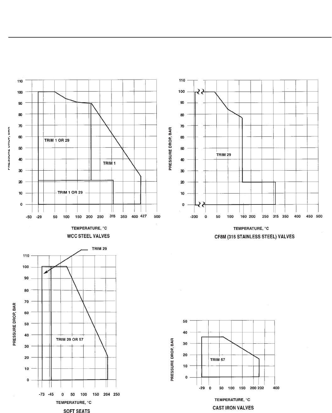
17
Trim Material Pressure/Temperature Capabilities for Valve Sizes
through DN 300 x 200 (NPS 12 x 8) for ED, ES, and ET Trim

easy-e Valves
Product Flier
PF51.1:E
July 2008
18
Trim Material Pressure/Temperature Capabilities for EZ Trim
EZ Trim Temperature Capabilities
BODY
MATERIAL
FISHER TRIM
NUMBER
VALVE SIZE TEMPERATURE,
_CNOTES
DN NPS
Cast iron
101 All All 29 to 232 - - -
129 All All 73 to 232 With non-lubricating
fluids, limit to 149_C
WCC Steel
101 All All 29 to 427 - - -
129
to 50
80
100
to 2
3
4
29 to 260
29 to 371
29 to 338
With non-lubricating
fluids, limit to 149_C
CF8M (316 stainless
steel)
101
to 40
50
80
100
to 1-1/2
2
3
4
29 to 354
29 to 288
29 to 216
12 to 177
- - -
129
to 40
80
100
to 2
3
4
198 to 260
198 to 377
198 to 371
With non-lubricating
fluids, limit to 149_C

easy-e Valves
Product Flier
PF51.1:E
July 2008
19
ED, ES, and ET Flow Coefficients
FLOW
CHARAC-
TERISTIC
VALVE SIZE
MAXI-
MUM
TRAVEL
PORT
DIA.
ED AND ET
(FLOW DOWN) ES (FLOW UP)
Valve Opening, Percent of Total Travel
10 30 70 100 100 10 30 70 100 100
DN NPS mm mm CVFLCVFL
Quick
Opening
- - -
- - -
25
40
50
1/2
3/4
1, 1-1/4
1-1/2
2
19
19
19
19
29
33.3
33.3
33.3
47.6
58.7
- - -
- - -
4.86
7.79
13.4
- - -
- - -
13.4
20.5
39.9
- - -
- - -
21.1
39.4
73.7
- - -
- - -
22.1
44.0
77.6
- - -
- - -
.81
.79
.77
4.00
4.94
5.24
7.60
14.3
6.22
11.8
15.0
22.3
48.6
6.52
14.2
21.1
38.0
67.2
6.53
14.2
21.4
38.0
67.2
.88
.83
.89
.94
.93
65
80
100
150
200
2-1/2
3
4
6
8
38
38
51
51
76
73.0
87.3
111.1
177.8
203.2
20.9
27.2
37.7
73.6
135
58.8
77.9
125
232
434
103
149
238
416
759
109
161
251
460
863
.81
.77
.79
.82
.85
21.8
23.3
39.0
89.9
156
66.6
78.3
132
255
490
93.1
136
225
418
796
93.1
150
235
469
875
.91
.87
.89
.82
.85
XT - - -XT - - -
- - -
- - -
25
40
50
1/2
3/4
1, 1-1/4
1-1/2
2
19
19
19
19
29
33.3
33.3
33.3
47.6
58.7
- - -
- - -
.556
.494
.605
- - -
- - -
.724
.682
.737
- - -
- - -
.566
.649
.641
- - -
- - -
.556
.597
.623
- - -
- - -
- - -
- - -
- - -
.681
.576
.540
.577
.633
.653
.605
.656
.639
.619
.624
.534
.663
.743
.797
.622
.534
.650
.789
.810
- - -
- - -
- - -
- - -
- - -
65
80
100
150
200
2-1/2
3
4
6
8
38
38
51
51
76
73.0
87.3
111.1
177.8
203.2
.601
.626
.623
.664
.643
.738
.745
.733
.667
.757
.669
.619
.689
.728
.857
.652
.577
.694
.710
.827
- - -
- - -
- - -
- - -
- - -
.659
.585
.642
.572
.520
.720
.602
.714
.601
.654
.848
.737
.769
.681
.818
.868
.720
.780
.700
.774
- - -
- - -
- - -
- - -
- - -
Linear
CVFLCVFL
25
40
50
65
1, 1-1/4
1-1/2
2
2-1/2
19
19
29
38
33.3
47.6
58.7
70.3
3.21
4.23
7.87
9.34
8.18
11.8
24.9
35.5
16.9
30.3
62.0
83.6
20.6
39.2
72.9
108
.84
.82
.77
.81
2.27
3.56
8.49
10.4
6.23
11.1
25.9
34.9
15.8
26.7
59.2
73.7
20.1
34.9
65.3
86.5
.89
.92
.91
.93
80
100
150
200
3
4
6
8
38
51
51
76
87.3
111.1
177.8
203.2
14.5
23.3
46.3
91.4
52.1
78.1
171
325
118
181
367
711
148
236
433
846
15.3
23.7
55.0
100
52.8
72.9
180
330
112
165
341
719
135
212
417
836
.89
.89
.81
.85
XT - - -XT - - -
25
40
50
65
1, 1-1/4
1-1/2
2
2-1/2
19
19
29
38
33.3
47.6
58.7
70.3
.340
.656
.641
.680
.494
.758
.728
.644
.610
.708
.683
.716
.636
.656
.638
.641
- - -
- - -
- - -
- - -
.691
.628
.618
.672
.690
.604
.689
.739
.709
.715
.742
.858
.690
.764
.762
.866
- - -
- - -
- - -
- - -
80
100
150
200
3
4
6
8
38
51
51
76
87.3
111.1
177.8
203.2
.671
.691
.656
.651
.697
.720
.744
.677
.707
.748
.784
.823
.620
.688
.740
.807
- - -
- - -
- - -
- - -
.607
.553
.597
.616
.663
.644
.701
.669
.762
.743
.787
.762
.751
.791
.745
.799
- - -
- - -
- - -
- - -
Equal
Percentage
CVFLCVFL
25
40
50
65
1, 1-1/4
1-1/2
2
2-1/2
19
19
29
38
33.3
47.6
58.7
73.0
.783
1.52
1.66
3.43
2.20
3.87
4.66
10.8
7.83
17.4
25.4
49.2
17.2
35.8
59.7
99.4
.88
.84
.85
.84
.783
1.54
1.74
4.05
1.86
3.57
4.72
10.6
9.54
17.2
25.0
45.5
17.4
33.4
56.2
82.7
.95
.94
.92
.93
80
100
150
200
3
4
6
8
38
51
51
76
87.3
111.1
177.8
203.2
4.32
5.85
12.9
27.0
10.9
18.3
43.3
105
66.0
125
239
605
136
224
394
818
.82
.82
.85
.86
4.05
6.56
13.2
25.9
10.0
17.3
41.1
97.8
59.0
103
223
618
121
203
357
808
.89
.91
.86
.85
XT - - -XT - - -
25
40
50
65
1, 1-1/4
1-1/2
2
2-1/2
19
19
29
38
33.3
47.6
58.7
73.0
.766
.780
.827
.778
.587
.716
.774
.678
.743
.690
.702
.661
.667
.679
.687
.660
- - -
- - -
- - -
- - -
.754
.674
.863
.747
.763
.694
.849
.745
.630
.698
.792
.783
.721
.793
.848
.878
- - -
- - -
- - -
- - -
80
100
150
200
3
4
6
8
38
51
51
76
87.3
111.1
177.8
203.2
.774
.731
.688
.644
.682
.643
.682
.636
.663
.672
.736
.725
.675
.716
.778
.807
- - -
- - -
- - -
- - -
.768
.722
.723
.825
.761
.739
.767
.681
.754
.718
.808
.735
.757
.822
.816
.827
- - -
- - -
- - -
- - -
easy-e Valves
Product Flier
PF51.1:E
July 2008
20
EZ Flow Coefficients (Flow Up)
VALVE SIZE MAXIMUM
TRAVEL
PORT
DIA.
QUICK OPENING - - - LINEAR
Valve Opening, Percent of Total Travel
10 30 70 100 100 - - - 10 30 70 100 100
DN NPS mm mm CVFL - - -CVFL
- - -
- - -
25
40
1/2
3/4
1
1-1/2
19
19
19
19
33.3
33.3
33.3
47.6
1.76
3.85
4.39
5.64
4.29
9.40
14.0
20.6
4.44
9.72
16.8
33.4
4.44
9.72
16.9
34.2
.83
.88
.94
.96
- - -
- - -
- - -
- - -
- - -
- - -
2.21
3.99
- - -
- - -
5.29
11.1
- - -
- - -
11.1
25.8
- - -
- - -
13.6
31.9
- - -
- - -
.96
.96
50
80
100
2
3
4
29
38
51
58.7
87.3
111.1
13.0
30.8
50.8
44.3
92.4
159
58.4
126
219
58.6
129
223
.94
.91
.88
- - -
- - -
- - -
6.08
15.4
21.3
18.0
43.4
57.5
42.8
93.8
157
52.4
110
209
.95
.92
.89
XT - - - - - -XT - - -
- - -
- - -
25
40
1-2
3/4
1
1-1/2
19
19
19
19
33.3
33.3
33.3
47.6
.364
.314
.400
.623
.764
.654
.523
.726
.894
.769
.500
.861
.894
.769
.494
.848
- - -
- - -
- - -
- - -
- - -
- - -
- - -
- - -
- - -
- - -
.638
.633
- - -
- - -
.638
.657
- - -
- - -
.636
.696
- - -
- - -
.834
.818
- - -
- - -
- - -
- - -
50
80
100
2
3
4
29
38
51
58.7
87.3
111.1
.548
.672
.733
.765
.713
.724
.831
.783
.809
.834
.774
.835
- - -
- - -
- - -
- - -
- - -
- - -
.560
.622
.554
.655
.692
.684
.779
.758
.677
.924
.888
.866
- - -
- - -
- - -
EQUAL PERCENTAGE
DN 25 (NPS 1) VALVE WITH MICRO-FORM AND
MICRO-FLUTE VALVE PLUG 19 mm TRAVEL
EQUAL PERCENTAGE CHARACTERISTIC
CVFLPORT
DIA.
CVFL
DN 25
DN 40
DN 50
DN 80
DN 100
1
1-1/2
2
3
4
19
19
29
38
51
33.3
47.6
58.7
87.3
111.1
.79
.80
1.65
3.11
4.90
1.80
1.91
4.30
9.12
13.5
7.59
9.84
32.8
60.4
96.7
13.2
28.1
53.8
114
190
.96
.97
.95
.92
.90
6.4(1)
9.5(1)
12.7(1)
19.1(1)
6.4(2)
6.4(3)
.075
.099
.133
.276
.0385
.0562
.175
.308
.492
.965
.0560
.101
.641
1.29
2.12
4.57
.162
.433
1.52
3.07
4.91
8.84
.354
1.07
.88
.89
.93
.97
.87
.90
XT - - -XT - - -
DN 25
DN 40
DN 50
DN 80
DN 100
1
1-1/2
2
3
4
19
19
29
38
51
33.3
47.6
58.7
84.3
111.1
.641
.726
.655
.619
.594
.598
.733
.520
.598
.560
.646
.597
.653
.586
.532
.886
.840
.899
.781
.834
- - -
- - -
- - -
- - -
- - -
6.4(1)
9.5(1)
12.7(1)
19.1(1)
6.4(2)
6.4(3)
.804
.795
.787
.723
.778
.692
.658
.641
.628
.588
.690
.639
.596
.560
.600
.603
.637
.597
.647
.662
.803
.919
.656
.624
- - -
- - -
- - -
- - -
- - -
- - -
1. Micro-Form valve plug.
2. Micro-Flute valve plug—1 flute.
3. Micro-Flute valve plug—3 flutes.
Conversion of Sizing Coefficients
Following are conversions for use with other common sizing equations.
Kv = (0.865)Cv
C1= 39.76(pXT)
Cg = CvC1
Km = FL2
Cs = 1/20(Cg). Cs is only applicable for inlet pressures up to 70 bar(a)

easy-e Valves
Product Flier
PF51.1:E
July 2008
21
EWD, EWS, and EWT Flow Coefficients
FLOW
CHARAC-
TERISTIC
VALVE SIZE
MAXI-
MUM
TRAVEL
PORT
DIA.
EWD AND EWT
(FLOW DOWN) EWS (FLOW UP)
Valve Opening, Percent of Total Travel
10 30 70 100 100 10 30 70 100 100
DN NPS mm mm CVFLCVFL
Quick
Opening
100 x 50
150 x 100
200 x 100
200 x 150
4 x 2
6 x 4
8 x 4
8 x 6
29
51
51
51
58.7
111.1
111.1
177.8
13.8
40.8
43.2
79.0
42.7
140
147
247
105
306
328
531
124
340
379
637
.82
.88
.89
.89
13.7
39.4
42.1
79.3
42.1
147
149
249
101
355
365
606
123
382
450
714
.89
.88
.85
.86
300 x 150
250 x 200
300 x 200
400 x 250
12 x 6
10 x 8
12 x 8
16 x 10
51
76
76
152
177.8
203.2
203.2
257.2
80.1
138
149
234
250
468
481
1220
621
903
1000
2080
817
1040
1260
2230
.82
.88
.79
.79
86.1
151
157
221
261
471
480
1190
641
918
957
2100
874
1000
1110
2210
.79
.93
.89
.87
XT - - -XT - - -
100 x 50
150 x 100
200 x 100
200 x 150
4 x 2
6 x 4
8 x 4
8 x 6
29
51
51
51
58.7
111.1
111.1
177.8
.571
.577
.629
.544
.662
.612
.631
.578
.714
.793
.809
.759
.693
.818
.817
.705
- - -
- - -
- - -
- - -
.639
.619
.578
.682
.652
.591
.560
.634
.843
.726
.733
.688
.793
.781
.704
.671
- - -
- - -
- - -
- - -
300 x 150
250 x 200
300 x 200
400 x 250
12 x 6
10 x 8
12 x 8
16 x 10
51
76
76
152
177.8
203.2
203.2
257.2
.515
.665
.687
.872
.613
.651
.727
.682
.715
.741
.744
.652
.782
.787
.636
.614
- - -
- - -
- - -
- - -
.614
.632
.718
.689
.571
.625
.712
.682
.677
.798
.855
.644
.736
.842
.836
.638
- - -
- - -
- - -
- - -
Linear
CVFLCVFL
100 x 50
150 x 100
200 x 100
200 x 150
4 x 2
6 x 4
8 x 4
8 x 6
29
51
51
51
58.7
111.1
111.1
177.8
6.80
21.4
23.2
44.0
23.0
78.7
80.6
170
70.8
201
211
405
107
320
340
617
.79
.86
.82
.88
6.88
26.2
25.1
52.5
21.5
78.4
78.1
182
60.0
197
192
435
96.2
320
328
607
.89
.89
.89
.88
300 x 150
250 x 200
300 x 200
400 x 250
12 x 6
10 x 8
12 x 8
16 x 10
51
76
76
152
177.8
203.2
203.2
257.2
51.7
95.9
104
307
176
336
348
834
458
798
907
1680
729
975
1160
2020
.81
.91
.80
.82
57.4
106
119
343
186
315
336
865
441
766
795
1680
675
958
1050
2080
.84
.92
.89
.87
XT - - -XT - - -
100 x 50
150 x 100
200 x 100
200 x 150
4 x 2
6 x 4
8 x 4
8 x 6
29
51
51
51
58.7
111.1
111.1
177.8
.625
.686
.694
.796
.691
.651
.691
.758
.582
.672
.676
.801
.654
.725
.753
.656
- - -
- - -
- - -
- - -
.599
.713
.610
.655
.728
.661
.682
.688
.744
.666
.716
.723
.794
.725
.729
.679
- - -
- - -
- - -
- - -
300 x 150
250 x 200
300 x 200
400 x 250
12 x 6
10 x 8
12 x 8
16 x 10
51
76
76
152
177.8
203.2
203.2
257.2
.716
.683
.700
.676
.691
.610
.647
.670
.661
.715
.711
.702
.633
.843
.696
.671
- - -
- - -
- - -
- - -
.523
.666
.678
.786
.612
.708
.811
.627
.704
.731
.809
.670
.719
.820
.836
.660
- - -
- - -
- - -
- - -
Equal
Percentage
CVFLCVFL
100 x 50
150 x 100
200 x 100
200 x 150
4 x 2
6 x 4
8 x 4
8 x 6
29
51
51
51
58.7
111.1
111.1
177.8
2.53
7.34
8.01
13.2
6.66
19.8
21.1
45.4
29.4
108
118
256
82.2
271
286
508
.82
.87
.85
.91
2.40
7.18
8.37
12.0
5.97
18.2
20.0
36.9
26.3
100
102
226
67.5
271
269
478
.90
.88
.90
.92
300 x 150
250 x 200
300 x 200
400 x 250
12 x 6
10 x 8
12 x 8
16 x 10
51
76
76
152
177.8
203.2
203.2
257.2
23.6
32.3
28.4
126
52.8
111
112
238
248
635
687
959
565
924
1090
2090
.79
.89
.81
.77
18.6
33.9
28.8
63.2
43.8
97.7
102
189
231
568
654
837
476
932
1020
1780
.88
.90
.88
.83
XT - - -XT - - -
100 x 50
150 x 100
200 x 100
200 x 150
4 x 2
6 x 4
8 x 4
8 x 6
29
51
51
51
58.7
111.1
111.1
177.8
.626
.996
.684
.837
.664
.711
.643
.719
.646
.630
.566
.626
.587
.712
.675
.684
- - -
- - -
- - -
- - -
.751
.794
.761
.733
.781
.775
.716
.874
.732
.718
.701
.773
.777
.694
.704
.727
- - -
- - -
- - -
- - -
100 x 50
150 x 100
200 x 100
200 x 150
4 x 2
6 x 4
8 x 4
8 x 6
51
76
76
152
177.8
203.2
203.2
257.2
.628
.725
.666
.655
.694
.687
.667
.640
.695
.595
.664
.503
.627
.802
.663
.546
- - -
- - -
- - -
- - -
.661
.836
.769
.565
.824
.894
.928
.501
.764
.699
.651
.497
.788
.760
.766
.652
- - -
- - -
- - -
- - -
easy-e Valves
Product Flier
PF51.1:E
July 2008
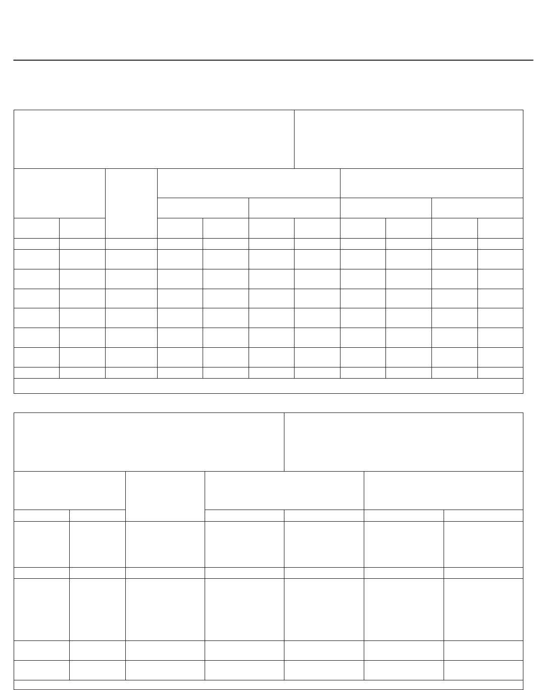
22
Actuator Selection for Plain Bonnets and Standard Spring-Loaded PTFE Packing
The following tables allow you to select an actuator
that will operate the valve at standard actuator
pressures.
It is not implied that the selections shown are best
for your application. In many cases, a smaller
actuator might be satisfactory for lower pressure
drops, and higher pressure drops might be possible
by using higher actuator pressures. Your sales office
can help you with more detailed actuator selection.
DThe actuator selections have been made at
maximum valve travel using plain bonnets and
standard valve stem diameter.
DThe selections are valid to 232_C only (204_C
for soft-seat constructions). For higher temperatures,
your sales office can provide actuator selections for
graphite ribbon/filament packing or extension
bonnets.
DActuator force does not exceed maximum
allowable stem load of standard 316 stainless steel
stem material at 232_C.
DDo not exceed the maximum inlet pressure of
the valve (valve body rating) nor the pressure drop
limits on pages 17 and 18.
657 and 667 Actuators
ED and EWD Valve: Metal Seat with Class II Shutoff and Flow Down
Maximum Inlet Pressure: Through EN PN 100 and ASME CL600
Maximum Shutoff Pressure Drop: As shown below unless limited by body
pressure-temperature rating or trim capabilities at high temperatures
Process Fluid Temperature: With plain bonnet, 18 to 232_C for metal seats
Ambient Temperature: 40 to 82_C with standard actuator materials; also refer to
temperature limits of accessories
Valve and Bonnet: Cast iron, steel, or stainless steel
Trim: Any listed in this flier
Gaskets: Any listed in this flier
Packing: Single PTFE V-ring
Other Valve Parts: Steel or stainless steel
Valve Size or Nominal Trim Size Port
Diameter,
mm
Air to Close (657 Actuator)
0 to 1.2 Bar (0 to 18 psig)
Air to Diaphragm Except
Where Indicated
Air to Open (667 Actuator)
0 to 1.2 bar (0 to 18 psig)
Air to Diaphragm Except
Where Indicated
DN NPS Actuator Size Pressure Drop,
Bar Actuator Size Pressure Drop,
Bar
25 1 or 1-1/4 33.3 30 99.3 30 99.3
40 1-1/2 33.3
47.6
30
34
99.3
99.3
30
34
99.3
99.3
50 2 33.3
58.7
40
40
99.3
91.0
40
40
99.3
91.1
65 2-1/2 47.6
73.0
40
45
99.3
99.3
40
45
99.3
99.3
80 3 58.7
87.3
45
45
99.3
98.9
45
45
99.3
98.9
100 4 73.0
111.1
45
45
99.3
83.8
45
45
99.3
41.2
150 6 111.1
177.8
50
70
80.5
99.3
70
70
99.3
99.3
200 8 203.2 - - -(1) 99.3(1) - - -(1) 99.3(1)
1. Use a size 70 actuator with 0 to 2.4 bar air to diaphragm.
easy-e Valves
Product Flier
PF51.1:E
July 2008
23
657 and 667 Actuators (Continued)
ET and EWT Valve: Flow Down
Maximum Inlet Pressure: Through EN PN 100 and ASME CL600
Maximum Shutoff Pressure Drop: As shown below unless limited by body
pressure-temperature rating or trim capabilities at high temperatures
Process Fluid Temperature: With plain bonnet, 18 to 204_C for soft seats and
to 232_C for metal seats
Ambient Temperature: 40 to 82_C with standard actuator materials; also refer
to temperature limits of accessories.
Valve and Bonnet: Cast iron, steel, or stainless steel
Trim: Any listed in this flier
Gaskets: Any listed in this flier
Packing: Single PTFE V-ring
Other Valve Parts: Steel or stainless steel
Valve Size or
Nominal Trim Size Port
Diameter,
mm
Air to Close (657 ACtuator)
0 to 1.2 Bar (0 to 18 psig)
Air to Diaphragm Except Where Indicated
Air to Open (667 Actuator)
0 to 1.2 Bar (0 to 18 psig)
Air to Diaphragm Except Where Indicated
Metal Seat
Class IV Shutoff
Soft Seat
Class V Shutoff Class IV Shutoff Soft Seat
Class V Shutoff
DN NPS Actuator
Size
Pressure
Drop, Bar
Actuator
Size
Pressure
Drop, Bar
Actuator
Size
Pressure
Drop, Bar
Actuator
Size
Pressure
Drop, Bar
25 1 or 1-1/4 33.3 34 99.3 34 99.3 34 99.3 34 99.3
40 1-1/2 33.3
47.6
34
34
99.3
99.3
34
34
99.3
95.0
34
34
99.3
99.3
34
34
99.3
94.9
50 2 33.3
58.7
40
45
99.3
99.3
40
45
99.3
99.3
40
45
99.3
99.3
40
45
99.3
99.3
65 2-1/2 47.6
73.0
40
45
99.3
86.9
40
45
92.2
78.7
40
45
99.3
86.9
40
45
92.2
99.3
80 3 58.7
87.3
45
45
99.3
61.7
45
45
99.3
59.8
45
45
99.3
61.7
45
45
99.3
59.8
100 4 73.0
111.1
45
45
86.9
46.7
45
45
78.7
48.6 45 99.3
60.9(2)
45
- - -(2)
99.3
59.2(2)
150 6 177.8 60
- - -(1)
99.3
49.8(1)
60
70
92.5
65.0
70
- - -(1)
99.3
99.3(1)
70
70
99.3
65.0
200 8 203.2 - - -(1) 9.2(1) - - -(1) 81.8(1) - - -(1) 79.8(1) - - -(1) 99.3(1)
1. Use a size 70 actuator with 0 to 2.4 bar (0 to 33 psig) air to diaphragm.
2. Use a size 45 actuator with 0 to 2.4 bar (0 to 33 psig) air to diaphragm.
EZ Valve: Metal Seat (Class IV Shutoff) or PTFE Seat (Class VI Shutoff, and Flow Up)
Maximum Inlet Pressure: Through EN PN 100 and ASME CL600
Maximum Shutoff Pressure Drop: As shown below unless limited by body
pressure-temperature rating or trim capabilities at high temperatures
Process Fluid Temperature: With plain bonnet, 18 to 232_C for soft seats
and 232_C for metal seats
Ambient Temperature: 40 to 82_C with standard actuator materials; also
refer to temperature limits of accessories
Valve and Bonnet: Cast iron, steel, or stainless steel
Trim: Any listed in this flier
Gaskets: Any listed in this flier
Packing: Single PTFE V-ring
Other Valve Parts: Steel or stainless steel
Valve Size Port
Diameter,
mm
Air to Close (657 Actuator)
0 to 1.2 Bar (0 to 18 psig)
Air to Diaphragm Except
Where Indicated
Air to Open (667 Actuator)
0 to 1.2 bar (0 to 18 psig)
Air to Diaphragm Except
Where Indicated
DN NPS Actuator Size Pressure Drop, Bar Actuator Size Pressure Drop, Bar
25 and 40 1/2, 3/4, 1 and
1-1/2
6.4
9.5
12.7
19.1
25.4
30
30
30
34
34
99.3
99.3
99.3
76.5
34.1
30
30
30
34
34
99.3
99.3
99.3
76.5
40.2
40 1-1/2 38.1 34 15.4 34 15.4
50 2
6.4
9.5
12.7
19.1
25.4
38.1
50.8
40
40
40
45
45
45
45
99.3
99.3
99.3
99.3
58.3
23.4
11.8
40
40
40
45
45
45
45
99.3
99.3
99.3
99.3
58.3
23.4
11.8
80 3 50.8
76.2
45
- - -(1)
3.2
7.1(1)
45
- - -(1)
11.8
10.1(1)
100 4 50.8
101.6
45
- - -(1)
11.8
3.2(1)
45
- - -(1)
11.8
2.7(1)
1. Use a size 45 actuator with 0 to 2.4 bar (0 to 33 psig) air to diaphragm.
easy-e Valves
Product Flier
PF51.1:E
July 2008
24
Typical Valve and Actuator Weight
VALVE SIZE TYPICAL
ACTUATOR
SIZE
APPROXIMATE
WEIGHT OF
VALVE AND
ACTUATOR, kg
DN NPS
- - -
25
40
50
1/2 and 3/4
1
1-1/2
2
30
30
30
40
25
27
34
59
65
80
100
150
2-1/2
3
4
6
40
45
45
50
68
95
116
202
200
100 x 50
150 x 100
200 x 100
8
4x2
6x4
8x4
70
40
45
45
523
123
236
316
200 x 150
300 x 150
250 x 200
300 x 200
8x6
12x6
10x8
12x8
50
50
70
70
351
764
859
971
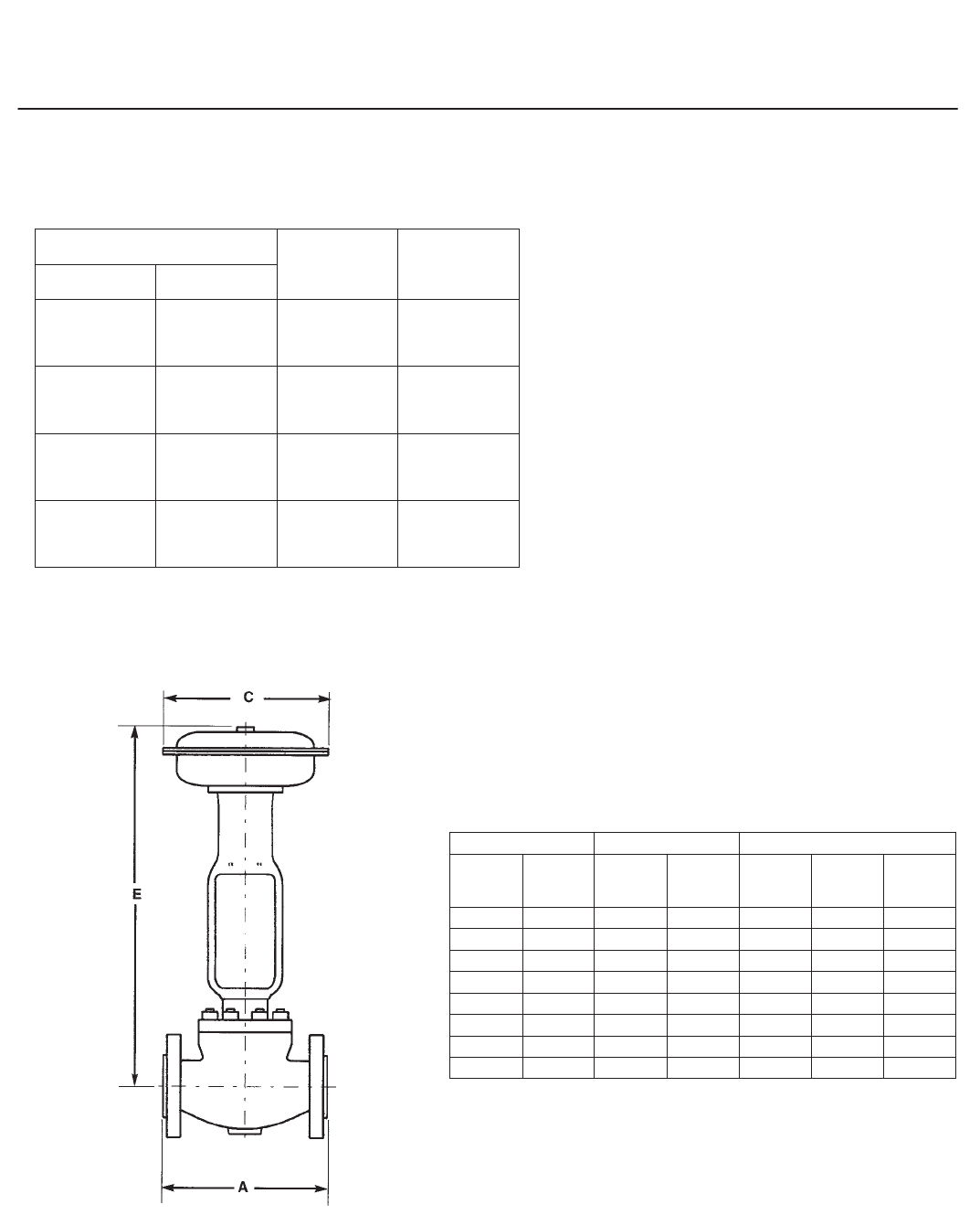
Typical Dimensions (Plain Bonnet and Standard Stem Diameter)
Face-to-Face Dimensions, A (mm)
VALVE SIZE EN ASME
DN NPS PN 16-40 PN
63-100
CL150
Raised
Face
CL300
Raised
Face
CL600
Raised
Face
25 1 160 230 184 197 210
40 1-1/2 200 260 222 235 251
50 2 230 300 254 267 286
65 2-1/2 290 340 276 292 311
80 3 310 380 298 317 337
100 4 350 430 353 368 394
150 6 480 550 451 473 508
200 8 600 650 543 568 613

easy-e Valves
Product Flier
PF51.1:E
July 2008
25
Dimensions (mm) with 585C Actuators Dimensions (mm) with 657 and 667 Actuators
VALVE SIZE ACTUA-
TOR
SIZE
C E
VALVE SIZE ACTUA-
TOR SIZE C
E
DN NPS DN NPS 657 667
25 1 and
1-1/4 25 205 480 25 1 and
1-1/4 30 34 289
333
567
625
605
700
40 1-1/2 25 205 477 40 1-1/2 30 34 289
333
564
622
602
697
50 2 25
50
205
257
518
668 50 2 40 45 333
406
713
824
759
933
65 2-1/2 25
50
205
257
540
690 65 2-1/2 40 45 333
406
735
846
781
955
80 3 25
50
205
257
544
694 80 3 45 406 850 959
100 4 25
50
205
257
574
724 100 4 45 406 880 989
150 6 50 257 754 150 6
50
60
70
406
473
536
973
973
1091
1035
1035
1184
200 8 70 536 1215 1308
easy-e Valves
Product Flier
PF51.1:E
July 2008
26
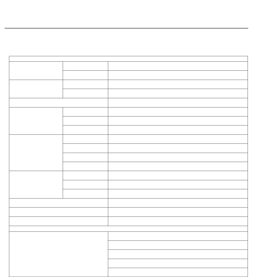
Ordering Information
When ordering, please specify . . .
Application
Type of Application
Throttling or on-off
Reducing or relief
Controlled Fluid
Include chemical analysis
of fluid if possible
Specific gravity
Fluid Temperature
Inlet Pressures
Minimum
Normal
Maximum
Pressure Drops
Minimum flowing
Normal flowing
Maximum flowing
Maximum at shutoff
Flow
Minimum controlled
Normal
Maximum
Maximum Permissible Noise Level, if Critical
Shutoff Classification Required
Line Size, Schedule, and End Connection Type
Valve, Actuator, and Accessories
From this or other product flier, select your choice wherever
a choice is offered. If you cannot find the selection you
need, contact your nearest sales office.
Note
Neither Emerson, Emerson Process
Management, nor any of their affiliated
entities assumes responsibility for the
selection, use and maintenance of any
product. Responsibility for the
selection, use and maintenance of any
product remains with the purchaser
and end user.

easy-e Valves
Product Flier
PF51.1:E
July 2008
27

easy-e Valves
Product Flier
PF51.1:E
July 2008
28
Sales Offices
For the name and location of your nearest sales office, refer to
www.emersonprocess.com/Fisher/support/contactus/index.html or contact our headquarters:
Europe
Emerson Process Management
Prince Regent House
Chatham Maritime Kent ME4 4QZ
United Kingdom
T +44 (0)16 34 89 58 00
F +44 (0)16 34 89 58 42
Middle East and Africa
Emerson Process Management
P.O. Box 17 003
Jebel Ali Free Zone
Dubai
United Arab Emirates
T +(971) 4 883 5235
F +(971) 4 883 5312
Russia
Emerson Process Management
Malaya Trubetskaya
Street 8 - 11th Floor
119881 Moscow
T (7) 095 232 69 68
F (7) 095 245 86 85
Latin America
Emerson Process Management
Av. Hollingsworth 325
Iporanga Sorocaba, SP
CEP 18.087-105
Brazil
T +(55)(15)3238-3788
F +(55)(15)3238-3300
Asia Pacific
Emerson Process Management
Asia Pacific Pte Ltd
1 Pandan Crescent
Singapore 128461
Singapore
T +(65) 6777 8211
F +(65) 6777 8010
Japan
Nippon Fisher Co. Ltd.
Shinagawa NF Building
4th Floor, 1-2-5 HigashiShinagawa
ShinagawaKu, Tokyo, 140-0002
Japan
T (81)-3-5769-6900
F (81)-3-5769-6901
North America
Emerson Process Management
301 S. 1st Avenue
Marshalltown IA 50158
USA
T (641) 754-3011
F (641) 754-2830
Emerson Process Management
Marshalltown, Iowa 50158 USA
Sorocaba, 18087 Brazil
Chatham, Kent ME4 4QZ UK
Dubai, United Arab Emirates
Singapore 128461 Singapore
EFisher Controls International LLC 1997, 2008; All Rights Reserved
www.Fisher.com
The contents of this publication are presented for informational purposes only, and while every effort has been made to ensure their accuracy, they
are not to be construed as warranties or guarantees, express or implied, regarding the products or services described herein or their use or
applicability. All sales are governed by our terms and conditions, which are available upon request. We reserve the right to modify or improve the
designs or specifications of such products at any time without notice. Neither Emerson, Emerson Process Management, nor any of their affiliated
entities assumes responsibility for the selection, use or maintenance of any product. Responsibility for proper selection, use, and maintenance of
any product remains solely with the purchaser and end user.
Fisher, easye, Cavitrol, ENVIRO-SEAL, FIELDVUE, ValveLink, and Whisper Trim are marks owned by one of the companies in the Emerson
Process Management business division of Emerson Electric Co. Emerson Process Management, Emerson, and the Emerson logo are trademarks
and service marks of Emerson Electric Co. HART is a mark owned by the HART Communications Foundation. FOUNDATION fieldbus is a mark
owned by the Fieldbus Foundation. All other marks are the property of their respective owners.
