Emerson Fisher Easy E Et Data Sheet
2015-03-30
: Emerson Emerson-Fisher-Easy-E-Et-Data-Sheet-680764 emerson-fisher-easy-e-et-data-sheet-680764 emerson pdf
Open the PDF directly: View PDF ![]() .
.
Page Count: 28
www.Fisher.com
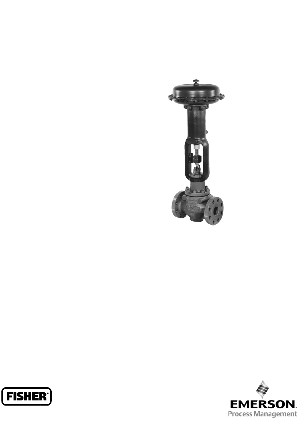
FisherrET, EAT, and ETR
Sliding-Stem Control Valves
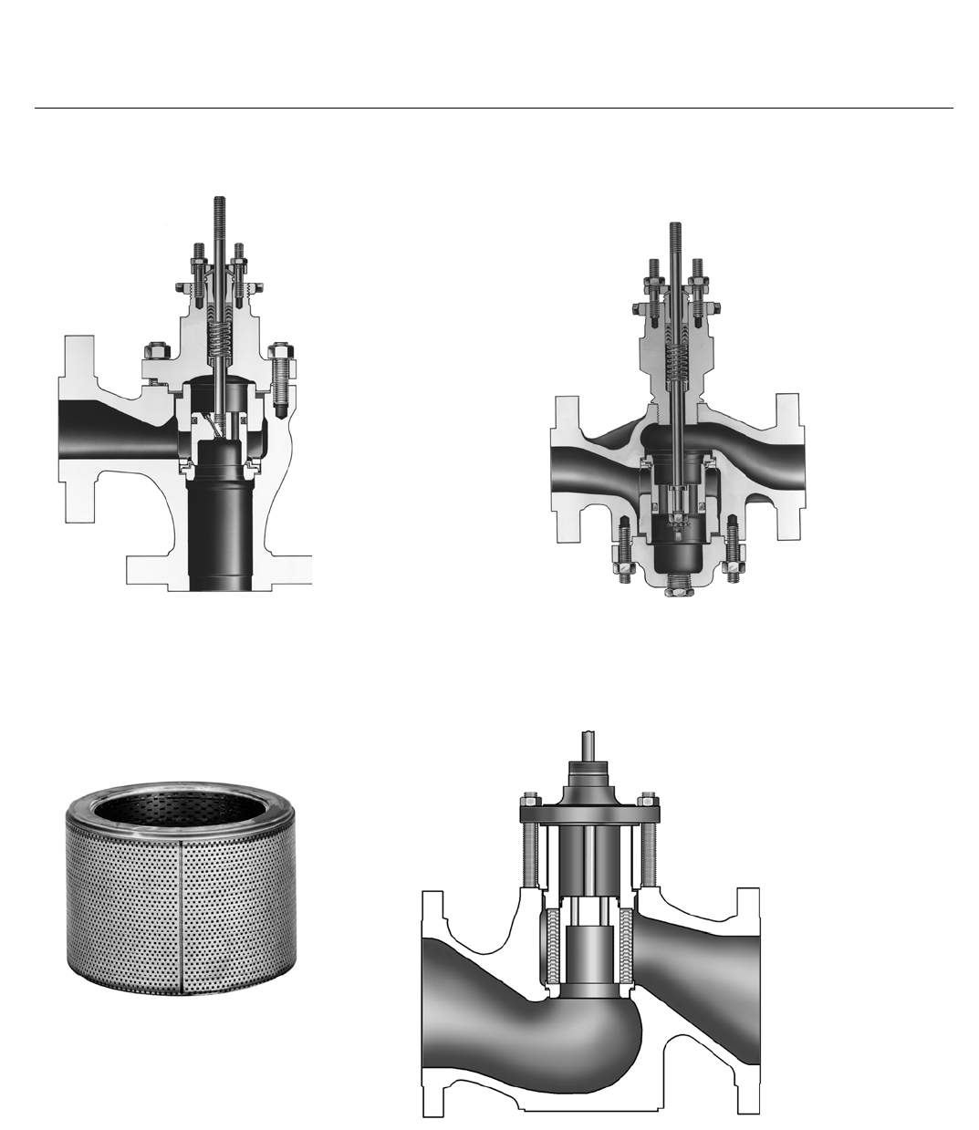
Fisher ET, EAT, and ETR general-purpose control valves
(figures 1, 2, and 3) are used for throttling or on-off
controlofawidevarietyofliquidsandgases.Allthree
valve designs have single ports, balanced valve plugs,
and cage guiding. Metal-to-PTFE seating for stringent
shutoff requirements is standard in all valves except
those with CavitroltIII cages. Metal-to-metal seating
forhighertemperaturesisstandardforvalveswith
Cavitrol III cages and optional for all other valves.
The temperature limits of ET valves can be extended
above 232_C(450_F) by using PEEK
(PolyEtherEtherKetone) anti-extrusion rings in
combination with a spring-loaded PTFE seal. The PEEK
anti-extrusion rings expand to close off the clearance
gapbetweentheplugandthecagewherethePTFE
seal may extrude at high temperatures and pressures.
The temperature limits are extended to 316_C (600_F)
for non-oxidizing service and to 260_C(500_F) for
oxidizing service.
The ET product line is available for a wide range of
applications, including sulfide and chloride
stress-cracking environments common to the oil and
gas production industries. To discuss available
constructions, contact your Emerson Process
Management sales office and include the applicable
codes and standards required for these environments.
The easy-etValve Family
ET, EAT, and ETR control valves are part of the versatile
easy-e family of Fisher industrial control valves. easy-e
valves share the following characteristics:
Multiple trim material choices
Interchangeable, restricted-capacity trims and
full-sized trims to match variable process flow
demands
FISHER ET CONTROL VALVE
WITH 667 ACTUATOR
W1916-3
Different cage/plug styles that provide particular
flow characteristics for highly-specialized
applications. The standard cage comes in three
different flow characteristics: Jquick-opening,
Jlinear, or Jequal percentage.
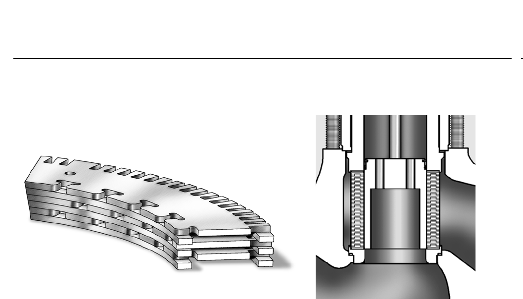
Whisper TrimtI, Whisper Trim III (figure 6), and
WhisperFlotcages (figures 4 and 5) attenuate
aerodynamic noise in gaseous service.
To help eliminate cavitation damage in a
properly-sized valve, a standard-travel, Cavitrol III,
one-stage cage (figure 8) and a long-travel, Cavitrol
III, two-stage cage are available in the NPS 1
throughNPS8ETcontrolvalve.
ET Valve
D100022X012
Product Bulletin
51.1:ET
December 2012

ET Valve
D100022X012
Product Bulletin
51.1:ET
December 2012
2
Features
Compliance with the Clean Air Act–ENVIRO-SEAL™
packing systems (figures 9 and 10) that provide an
improved stem seal to help prevent the loss of
process fluid are available. These packing systems
featurePTFEorGraphiteULFpackingwith
live-loading for reduced packing maintenance.
PTFE Seating for Long-Lasting Shutoff
Capability–Controlled compression of standard
seat construction protects PTFE disk between metal
disk seat and disk retainer (figure 1). Only the edge
of the PTFE disk is contacted by the flowstream
during normal operation. Excellent shutoff is
maintained by a backup ring or spring-loading that
forces the valve plug seal ring against the cage
(figure 1).
Valve Plug Stability– Rugged cage guiding provides
high valve plug stability, which reduces vibration
and mechanical noise.
Cost-Effective Operation and Maintenance
Economy–Increased wear resistance of hardened
stainless steel trim means longer-lasting service.
When inspection or maintenance is necessary, the
body can stay in the pipeline during removal of trim
parts. Balanced valve plug construction permits use
of smaller, lower-cost Fisher actuators. The ETR
valve also permits easy body interior access without
having to remove the bonnetoractuator(figure3).
And, trim inventory costs are cut because
dimensional standardization permits use of most
standard easy-etrimparts.
Compliance with European Standards–Valvesare
available with dimensions specified by EN/DIN
standards. See figure 15.
Sour Service Capability– Unless otherwise noted,
references are to NACE MR0175-2002. Optional
materials are available to meet NACE MR0103 and
NACE MR0175 / ISO 15156. Material requirements
under these standards vary by edition and year of
issue; the specific standard must be specified.
Table of Contents
Features 2.....................................
Specifications 3................................
ENVIRO-SEAL Packing System
Specifications 4..............................
ENVIRO-SEAL and HIGH-SEAL
Packing Systems 6...........................
ANSI/FCI Class VI Shutoff
Capabilities 6................................
Tables
Available Constructions 5.......................
Shutoff Classifications 5........................
Class VI Shutoff Availability 6....................
Class VI Trim Materials 6........................
Trim Materials 10..............................
Materials and Temperature Limits for
Other Parts 17..............................
Valve Body/Trim Temperature
Capabilities 18.............................
Bonnet Selection Guidelines 19..................
Maximum Flow Coefficients 19..................
Port Diameters, Valve Plug Travel,
Stem and Yoke Boss Diameters 20.............
Metal Trim Parts 23............................
Bolting Materials and Temperature Limits 23......
Dimensions 24.................................
Ordering Information 27.........................

ET Valve
D100022X012
Product Bulletin
51.1:ET
December 2012
3
Specifications
Available Configurations
ET: Single-port, globe-style control valve with cage
guiding, balanced valve plug, and push-down-to-close
valve plug action (figure 1)
EAT: Angle version of ET control valve, used to
facilitate piping or in applications where a
self-draining valve is desired (figure 2)
ETR: Same as ET control valve except with
push-down-to-open valve plug action (figure 3)
Valve Sizes and End Connection Styles
Flanged raised-face per EN 1092-1/B and see table 1
Maximum Inlet Pressures and Temperatures(1,2)
As listed below, unless limited by maximum pressure
drop or material temperature capabilities
Valves with Cast Iron Bodies
Flanged: Consistent with CL125B or 250B per ASME
B16.1
Valves with Steel and Stainless Steel Bodies
Flanged: Consistent with CL150, 300, and 600(3) per
ASME B16.34
Screwed or Welding: Consistent with flanged CL600
per ASME B16.34
Maximum Pressure Drops(2)
Same as maximum inlet pressure for specific
construction defined above, except where further
limited as follows:
All Valves Except Those with Cavitrol III, Whisper Trim
III, and WhisperFlo Cages: Seefigure11.
Valves with Cavitrol III Cages: Seefigure12.
Valves with Whisper Trim III Cages: Seefigure13
except where further limited by the following max
P/P1 ratios(4) – 0.60 for level A3 cage, 0.75 for level
B3 cage, 0.85 for level C3 cage, or 0.99 for level D3
cage
Valves for NACE MR0175 / ISO 15156 and MR0103:
Seefigure14
Shutoff Classifications Per ANSI/FCI 70-2
and IEC 60534-4
Class IV, V, or VI. See tables 2, 3, or 4
Construction Materials
Body, Bonnet, and Bonnet Spacer or Bottom Flange, if
used: JCast iron, JWCC carbon steel, or JLCC
carbon steel, JWC9 chrome moly steel, JCF8M
(cast 316 stainless steel), or Jother materials upon
request
Valve Plug, Cage, and Metal Seating Parts:
All Valves Except Those with Cavitrol III or Whisper Trim
III Cages: See table 5
Valves with Cavitrol III Cages: See table 6
Valves with Whisper Trim III Cages: See table 8
Valves with WhisperFlo Cages: See table 7
Bellows Seal Assembly: J316L stainless steel or
JN04400
All Other Parts: See table 9
Material Temperature Capabilities(2)
Body/Trim Combinations:
All Valves Except Those with Cavitrol III or Whisper Trim
III Cages: Seefigure11
Valves with Cavitrol III Cages: See table 6
Valves with Whisper Trim III Cages: See table 8
Valves with WhisperFlo Cages: See table 7
Bolting For NACE MR0175 / ISO 15156 and MR0103:
See table 18
Bonnets: See table 11
All Other Parts: See table 9
Flow Characteristics
Standard Cages: JQuick-opening, Jlinear, or
Jequal percentage
Whisper Trim, WhisperFlo, and Cavitrol Cages: Linear
Flow Directions
ET
Standard Cage: Normally down
Whisper Trim and WhisperFlo Cages: Always up
Cavitrol Cage: Always down
EAT
Standard Cage with Liner for Metal Seat: Normally
down
Standard Cage without Liner: Flow up or down
Whisper Trim and WhisperFlo Cages: Always up
ETR
Standard Cage: Normally up
Whisper Trim Cage: Always down
Flow Coefficients and Noise Level Prediction
See table 12 and Catalog 12
For Whisper Trim III cage flow coefficients (other than
NPS 6 valves), contact your Emerson Process
Management sales office
-continued -

ET Valve
D100022X012
Product Bulletin
51.1:ET
December 2012
4
Specifications (continued)
Port Diameters and Maximum Valve Plug Travels
See tables 13 and 15
Yoke Boss and Stem Diameters
See table 14
Typical Bonnet Styles
See table 11
Packing Arrangements
Standard Material: Single PTFE V-ring
Optional Materials: See table 9
ENVIRO-SEAL Packing Systems: See figures 9 and 10
ENVIRO
-
SEAL Packing Systems in vacuum service:
Standard ENVIRO-SEAL packing systems can be used
in vacuum service with packing rings in standard
orientation. Do not reverse the ENVIRO-SEAL PTFE
packing rings. Also, see Bulletin 59.1:061,
ENVIRO-SEAL Packing Systems for Sliding-Stem
Valves
Approximate Weights
NPS 1: 14 kg (30 lb)
NPS 1-1/2: 20 kg (45 lb)
NPS 2: 39 kg (85 lb)
NPS 2-1/2: 45 kg (100 lb)
NPS 3: 57 kg (125 lb)
NPS 4: 77 kg (170 lb)
NPS 6: 159 kg (350 lb)
NPS 8: 408 kg (900 lb)
Additional Options
JLubricator, Jlubricator/isolating valve, Jdrilled
and tapped connection in extension bonnet for
leak-off service, Jbody drain plug, Jstyle 3
fabricated extension bonnet made on order to a
specific length for cryogenic service, Jstyle NS
bonnet for seismic service requirements, Jpackings
suitable for nuclear service, JClass V shutoff for ET
above 232_C(450_F) using PEEK anti-extrusion rings
1. EN (or other) ratings and end connections can usually be supplied; consult your Emerson Process Management sales office.
2. The pressure or temperature limits in this bulletin, and any applicable code limitations, should not be exceeded.
3. Certain bonnet bolting material selections may require a CL600 easy-e valve assembly to be derated. Contact your Emerson Process Management sales office for more information.
4. Limitation based on excessive noise increase if max P/P1ratio for a given cage level is exceeded.
ENVIRO-SEAL Packing System Specifications
Applicable Stem Diameters
J9.5 mm (3/8 inches), J12.7 mm (1/2 inches),
J19.1 mm (3/4 inches), J25.4 mm (1 inch), and
J31.8 mm (1-1/4 inches) diameter valve stems
Maximum Pressure/Temperature Limits(1)
To Meet the EPA Fugitive Emission Standard of 100
PPM(2)
For ENVIRO
-
SEAL PTFE and ENVIRO
-
SEAL Duplex packing
systems: full CL300 up to 232_C(450_F)
For ENVIRO
-
SEAL Graphite ULF packing: 104 bar (1500
psig) at 316_C(600_F)
Construction Materials
PTFE Packing Systems
Packing Ring and Lower Wiper: PTFE V-ring(3)
Male and Female Adaptor Rings: Carbon-filled PTFE
V-ring
Graphite ULF Packing Systems: Graphite rings
Duplex Packing Systems:
Male and Female Adaptor Rings: Carbon-filled PTFE
V-ring
Guide Bushings: Carbon graphite
Packing Rings: Graphite composite
Packing Washer: PTFE
Anti-Extrusion Washer: Filled PTFE (not required for
Graphite ULF or duplex packing)
Lantern Ring: S31600 (316 stainless steel) (not
required for Graphite ULF packing)
Packing Box Flange: S31600
Spring: J17-7PH stainless steel or JN06600
Packing Follower: S31600 lined with carbon-filled
PTFE
Packing Box Studs: Strain-hardened 316 stainless
steel
Packing Box Nuts: 316 stainless steel SA194 Grade
8M
1. Refer to the valve specifications in this bulletin for pressure/temperature limits of valve parts. Do not exceed the pressure/temperature rating of the valve. Do not exceed any applicable code
or standard limitation.
2. The Environmental Protection Agency (EPA) has set a limit of 100 parts per million (ppm) for fugitive emissions from a valve in selected VOC (VolatileOrganicCompound)services.
3. In vacuum service, it is not necessary to reverse the ENVIRO-SEAL PTFE packing rings.
ET Valve
D100022X012
Product Bulletin
51.1:ET
December 2012
5
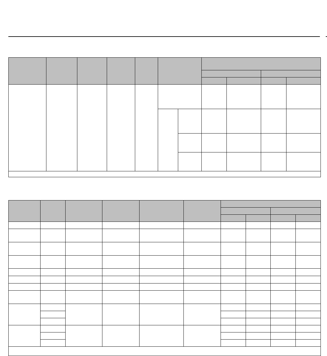
Table 1. Available Constructions
VALVE VALVE SIZE,
NPS
VALVE BODY MATERIAL AND END CONNECTION STYLE(1)
Cast Iron Valve Body Carbon Steel, Alloy Steel, or Stainless Steel Valve Body
CL125
FF Flanged
CL250
RF Flanged Screwed RF or RTJ Flanged Butt
Weld
Socket
Weld
CL150 CL300 CL600
ET 1, 1-1/2, or 2
2-1/2, 3, 4, 6, or 8
X
X
X
X
X
---
X
X
X
X
X
X
X
X
X
X
EAT 1or2
3, 4, or 6
---
---
---
---
---
---
X
X
X
X
X
X
X
X
X
X
ETR 1, 1-1/2, or 2
2-1/2, 3, or 4
---
---
---
---
X
---
X
---
X
---
X
---
X
---
X
---
VALVE VALVE SIZE,
DN
STEEL VALVE BODY MATERIAL AND RAISED-FACE END CONNECTION STYLE(2)
PN16 PN25 PN40 PN63 PN100
ET 25, 40, 50, 65, 80,
100, 150, or 200 X X X X X
EAT 25, 50, 80, 100, or
150 X X X X X
ETR 25, 40, 50, 65, 80,
or 100 X X X X X
X = Available Construction.
1. End connection style abbreviations: FF -Flat Faced, RF -Raised Face, RTJ -Ring Type Joint.
2. End connection EN1092-1/B.
Table 2. Shutoff Classifications Per ANSI/FCI 70-2 and IEC 60534-4
Valve Design Seating Shutoff Class
All except those with Cavitrol III cages PTFE VAirTest
V (optional)
VI (optional)(3)
Metal IV (standard)
V (optional)(1)
VI (optional)(3)
ET with Cavitrol III one-stage cage Metal IV (standard)
V (optional)
ET with Cavitrol III two-stage cages Metal V
ET and EAT w/ TSO (Tight Shutoff) trim
(CL125 through 600)
Replaceable,
protected soft seat
TSO(2)
TSO is not an ANSI/FCI leakage class.
Valves with TSO trim are factory tested to a more stringent Emerson Process
Management test requirement of no leakage at time of shipment. Test medium is
water. Specify service nP when ordering. Shutoff class V.
ET w/ TSO (Tight Shutoff) trim (CL125
through 600)
Std or Cavitrol III
trim. Replaceable,
protected soft seat.
1.ClassVshutoffrequiresspring-loaded seal ring, radius-seat plug, and wide-bevel seat ring (not available with 8-inch port, quick-opening cage). Not available with trims 4, 29, and 85.
2. For additional information, contact your Emerson Process Management sales office.
3. Refer to table 3.
ET Valve
D100022X012
Product Bulletin
51.1:ET
December 2012
6
ENVIRO-SEAL, HIGH-SEAL
Packing Systems
ENVIRO-SEAL and HIGH-SEAL packing systems offer
exceptional sealing capabilities. These systems easily
install in existing valves or can be purchased with new
valves. These systems help seal the process to
conserve valuable process fluid. The long-life and
reliability of these systems also reduce maintenance
costs and downtime.
For applications requiring compliance with
environmental protection regulations, the unique
ENVIRO-SEAL packing system (figure 10) and a unique
ENVIRO-SEAL bellows seal system (figure 9) are
offered. The emission control packing system keeps
emission concentrations below the EPA 100 ppm
requirement.
For an excellent stem seal in applications that are not
environmentally-sensitive, the HIGH-SEAL Graphite
ULF packing system (figure 10) is offered. The
HIGH-SEAL packing system provides improved sealing
at pressure/temperature ratings beyond ENVIRO-SEAL
limits.
ENVIRO-SEAL packing systems, available with PTFE,
Graphite ULF, or duplex packing, and the HIGH-SEAL
Graphite ULF packing system feature live-loading and
unique packing-ring arrangements for long-term,
consistent sealing performance.
ANSI/FCI Class VI Shutoff
Capabilities
ET valves with soft seat and metal seat constructions
can provide ANSI/FCI Class VI shut-off capabilities. See
tables 3 and 4.
Table 3. Class VI Shutoff Availability(1, 2)
Valve Port Size, Inches Seat Minimum Seat Load
ET ²3.4375 ±7Soft See Catalog 14
ET ²3.4375 ±7Metal 300 lbs/lineal inch
1. Limited retrofit capability. Consult your Emerson Process Management sales office.
2. Not for use with NPS 8.
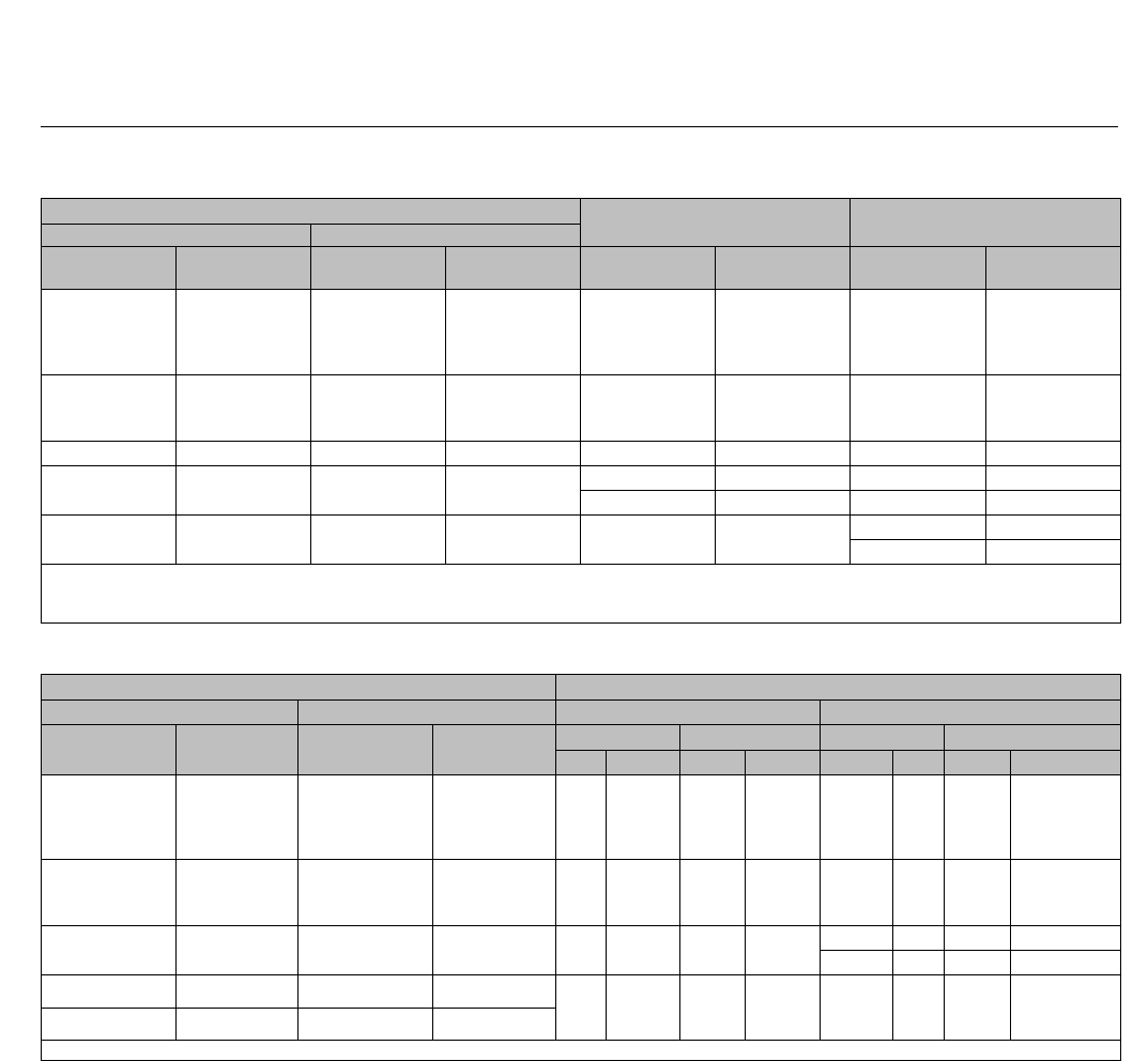
Table 4. Class VI Trim Materials
VALVE CAGE/SEAT
RING RETAINER VALVE PLUG SEAT RING SEAL RING TRIM TEMPERATURE LIMIT
_C_F
ET
S31600 / ENC
S31600 w/
standard beveled
seat
S31600/PTFE UHMWPE(1)
R30003 -198 to 66 -325 to 150
S31600 / ENC
S31600/CoCr-A
seat w/ radiused
seat (special
design)
S31600 w/ wide
beveled seat
(special design)
UHMWPE R30003 -198 to 66 -325 to 150
S17400 (17-4PH
SST)
S41600 w/
standard beveled
seat
S31600/PTFE UHMWPE R30003 -29 to 66 -20 to 150
S17400
S41600 w/ radiused
seat (special
design)
S31600 w/ wide
beveled seat
(special design)
UHMWPE R30003 -29 to 66 -20 to 150
1. UHMWPE (Ultra High Molecular Weight Polyethylene)
ET Valve
D100022X012
Product Bulletin
51.1:ET
December 2012
7
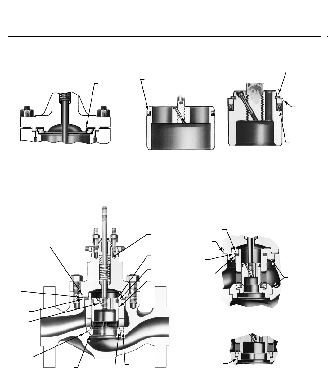
Figure 1. Fisher ET Sectional with Standard Cages
SEAL RING
NPS 6 OR 8 ET
W2914-1
RETAINING
RING
METAL
BACKUP
RING
SEAL RING
NPS 1 THROUGH 4 ET
(ALSONPS1THROUGH6EAT)
W0995-2
W3162-3
BONNET GASKET
SHIM
SPIRAL
WOUND
GASKET
PIN
SEAT RING
GASKET
METAL
DISK SEAT PTFE DISK METAL DISK
RETAINER
VALVE PLUG
SEAL RING
BACKUP RING
PTFE V-RING
PACKING
STANDARD NPS 1 THROUGH
6 CONSTRUCTION
W2001-2
CAGE
GASKET
SHIM
SPIRAL
WOUND
GASKET
RESTRICTED
TRIM
ADAPTORS
OPTIONAL RESTRICTED TRIM
BONNET
GASKET
METAL
SEAT
RING
OPTIONAL METAL-TO-METAL
SEATING
W0983-2
SPRING-LOADED SEAL RING CONSTRUCTION
FOR USE WITH CAVITROL CAGES AND FOR
METAL SEAT WITH OPTIONAL
CLASS V SHUTOFF
W7019-1
LOAD
RING
STANDARD NPS 8
CONSTRUCTION
ET Valve
D100022X012
Product Bulletin
51.1:ET
December 2012
8
Figure 2. Fisher EAT Sectional
W0972-3
Figure 3. Fisher ETR Sectional
W1557-4
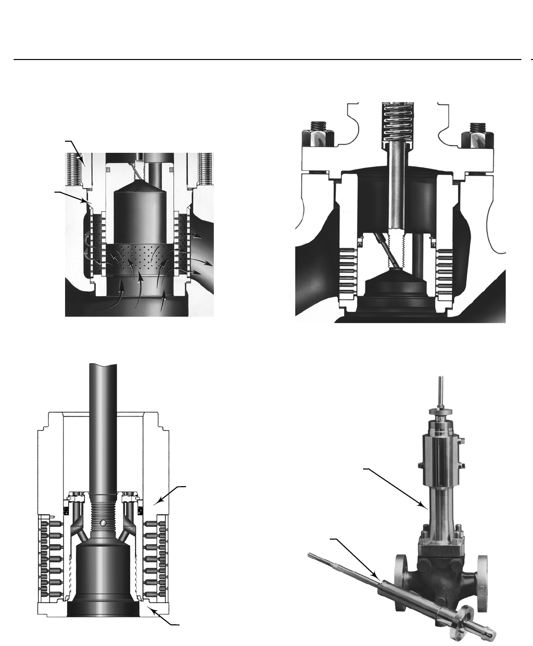
Figure 4. Typical Valve with WhisperFlo Aerodynamic Trim
W6980
WhisperFlo TRIM
W6851-1
ET Valve
D100022X012
Product Bulletin
51.1:ET
December 2012
9
Figure 5. Typical WhisperFlo Cage
W7065
W6851-1

ET Valve
D100022X012
Product Bulletin
51.1:ET
December 2012
10
Table 5. Typical Combinations of Metal Trim Parts for All Valves Except Those for NACE MR0175 / ISO 15156 and
MR0103 Specifications(1),CavitrolIII
(2),6-Inch Whisper Trim III(3),and4-,6-,and8-Inch WhisperFlo Cages(6)
Trim Designation Valve Plug Cage
Disk Seat and Retainer
for
Standard
PTFE-Seat
Construction
Seat Ring or
Liner for Optional
Metal-Seat Construction
Optional Liner
(Metal Seat
EAT Valve
Only)
1 (typically used with optional
metal-seat constructions in all
designs and body materials
except CF8M)
S41600 HT CB7Cu-1HT
––– S41600 HT or CA15 HT(4) S41600 HT
S17400 HT(5) CB7Cu-1HT
(5)
3
S31600
with seat and guide
hard faced with
CoCr-A
hardfacing alloy
R30006 (alloy 6) ––– R30006 (alloy 6) –––
4(7) S31600 CB7Cu-1HT S31600 S31600 S31600
27
S31600
with seat and guide
hard faced with
CoCr-A
hardfacing alloy
CF8M with
electroless nickel
coating (ENC)
S31600
disk retainer with
CoCr-Adiskseat
R30006 (alloy 6) –––
28(8)
S31600
with seat hard faced
with CoCr-A
hardfacing alloy
CF8M with
electroless nickel
coating (ENC)
S31600
disk retainer with
CoCr-Adiskseat
R30006 (alloy 6) –––
29 (standard for CF8M bodies in
all designs regardless of seat
construction)(8)
S31600
CF8M with
electroless nickel
coating (ENC)
S31600 S31600 S31600
37 and 37H (trim 37H has
clearances for high-temperature
service above 210_C[410_F])
S31600
with seat and guide
hard faced with
CoCr-A
CB7Cu-1HT
S31600
disk retainer with
CoCr-Adiskseat
Seat Ring:
R30006 (alloy 6) –––
57 (standard for standard
PTFE-seat ET, EAT, ETR in all body
materials except CF8M)
S41600 HT S17400 HT S31600 ––– –––
1. For NACE MR0175 / ISO 15156 and MR0103 specification trims, see table 17
2. For Cavitrol III trims, see table 6.
3. For 6-inch Whisper Trim III trims with 5.375 inch port diameter, see table 8
4. CA15 is used for NPS 6 and 8 full-sized and restricted-trim valves.
5. For 8-inch Whisper Trim I and 8-inch Whisper Trim III.
6. For 4-,6-,and8-Inch WhisperFlo trims, see table 7.
7. Not for use with Whisper Trim I.
8. Not for use with Whisper Trim I with 136 mm (5.375 inch) and larger ports.
ET Valve
D100022X012
Product Bulletin
51.1:ET
December 2012
11
Table 6. Cavitrol III(1) Metal Trim Part Materials and Body/Trim Temperature Capabilities
TRIM
DESIGNATION
VALVE
PLUG CAGE CAGE
RETAINER
SEAT
RING BODY & BONNET
MATERIAL TEMPERATURE
CAPABILITY
_C_F
Minimum Maximum Minimum Maximum
76 Heat-treated
S42000
S17400 SST
H900 for
Cavitrol III
1-stage
or
S17400 SST
H1075 for
Cavitrol III
2-stage
S31600 S17400
with H900
heat-treat
condition
WCC carbon steel,
WC9 chrome moly
steel, or LCC carbon
steel
-29 These materials
not limiting
factors
-20 These materials
not limiting
factors
CF8M NPS 1,
1-1/2, or 2
valve body
size
-29 These materials
and sizes not
limiting factors
-20 These materials
and sizes not
limiting factors
NPS 2-1/2
or 3 valve
body size
-29 216 -20 420
NPS 4, 6,
or 8 valve
body size
-29 177 -20 350
1.AvailableonlyinNPS1through8ETvalves.
Table 7. WhisperFlo Metal Trim Part Materials and Valve Body/Trim Temperature Capabilities
(NPS 4, 6, and 8 Fisher ET only)
TRIM
DESIGNA-
TION
VALVE
BODY
VALVE
PLUG CAGE CAGE
RETAINER SEAT
MATERIAL TEMPERATURE CAPABILITY(1)
_C_F
Min Max Min Max
901 WCC S41600 S41000 WCC ENC S41600 -29 316 -20 600
902 WCC S31600/CoCrA
Seat and Guide S41000 WCC ENC S31600/CoCrA -29 316 -20 600
926 WCC S31600/CoCrA
Seat and Guide S41000 NACE WCC/NACE/ENC S31600/CoCrA -29 316 -20 600
936 316
CF8M
S31600/CoCrA
Seat and Guide
S31603/
R31233 S31600/ENC S31600/CoCrA -198 316 -325 600
901C WCC S41000 S41000 WCC ENC S31600/PTFE -29 232 -20 450
904C WCC S31600 S41000 WCC ENC S31600/PTFE -29 149 -20 300
984C WCC S31600 S41000 NACE WCC/NACE/ENC S31600/PTFE -29 149 -20 300
985C CF8M S31600 S31603/
R31233 S31600/ENC S31600/PTFE -73 149 -100 300
990
CD3MN
S31803/CoCrA
Seat and Guide
S31803/
R31233 S31800/Cr Plate S31803/CoCrA
Seat
-51 316 -60 600
LCC -46 316 -51 600
WCC -29 316 -20 600
990C
CD3MN
S31803/CoCrA
Seat and Guide
S31803/
R31233 S31800/Cr Plate S31803/PTFE
-51 232 -60 450
LCC -46 232 -51 450
WCC -29 232 -20 450
1. Temperatures above 232_C (450_F) require PEEK anti-extrusion rings and spring-loaded seal ring. This option allows ET construction to be used up to 316_C (600_F) for non-oxidizing service
and 260_C(500_F) for oxidizing service.

ET Valve
D100022X012
Product Bulletin
51.1:ET
December 2012
12
Table 8. Whisper Trim III Metal Trim Part Materials and Body/Trim Temperature Capabilities (NPS 6 Fisher ET with
5.375 inch port only)
Trim
Designation Valve Plug Cage Cage
Retainer
Baffle
(For Level
D3 Cage
Only)
Disk Seat
and Retainer
for
PTFE-Seat
Construction
Seat Ring for
Metal-Seat
Construction
Body
Bonnet,
&Bonnet
Spacer
Material Temperature
Capability
_C_F
301
(standard for
all body
materials
except
CF8M)
S17400 HT S41600 HT
Carbon steel
NACE with
electroless
nickel coating
(ENC)
Steel --- S41000 HT
WCC carbon
steel or WC9
chrome moly
steel
-29 to
316(1)
-20 to
600(1)
CF8M
(316 SST) -29 to 163 -20 to 325
301C (for
soft seats) S17400 HT S41600 HT
Carbon steel
NACE with
electroless
nickel coating
(ENC)
Steel S31600 ---
WCC carbon
steel or WC9
chrome moly
steel
-29 to 204 -20 to 400
CF8M
(316 SST) -29 to 163 -20 to 325
304
S31600
with seat
and guide
hard-faced
with CoCr-A
S41600 HT
Carbon steel
NACE with
electroless
nickel coating
(ENC)
Steel ---
S31600 with
seat
hard-faced
with CoCr-A
WCC carbon
steel or WC9
chrome moly
steel
-29 to
316(1)
-20 to
600(1)
CF8M
(316 SST) -29 to 177 -20 to 350
312
(for level D
NACE)
S31600
with seat
and guide
hard-faced
with CoCr-A
S31600
with
electroless
nickel
coating
(ENC)
S31600 with
electroless
nickel coating
(ENC)
S31600 ---
S31600 with
seat
hard-faced
with CoCr-A
WCC carbon
steel or WC9
chrome moly
steel
-29 to
260(1)
-20 to
500(1)
CF8M
(316 SST)
-198 to
316(1)
-325 to
600(1)
312C
(for level D
NACE)
S31600
with seat
and guide
hard-faced
with CoCr-A
S31600
with
electroless
nickel
coating
(ENC)
S31600 with
electroless
nickel coating
(ENC)
S31600 S31600 ---
WCC carbon
steel or WC9
chrome moly
steel
-29 to
260(1)
-20 to
500(1)
CF8M
(316 SST)
-198 to
316(1)
-325 to
600(1)
313 (NACE
compatible)
S31600
with seat
and guide
hard-faced
with CoCr-A
S31600
with
electroless
nickel
coating
(ENC)
Carbon steel
NACE with
electroless
nickel coating
(ENC)
Steel ---
S31600 with
seat
hard-faced
with CoCr-A
WCC carbon
steel or WC9
chrome moly
steel
-29 to 204 -20 to 400
CF8M
(316 SST)
-29 to
316(1)
-20 to
600(1)
313C (NACE
compatible)
(for soft
seats)
S31600
with seat
and guide
hard-faced
with CoCr-A
S31600
with
electroless
nickel
coating
(ENC)
Carbon steel
NACE with
electroless
nickel coating
(ENC)
Steel S31600 ---
WCC carbon
steel or WC9
chrome moly
steel
-29 to 204 -20 to 400
CF8M
(316 SST) -29 to 204 -20 to 400
1. Temperatures above 232_C (450_F) require PEEK anti-extrusion rings and spring-loaded seal ring. This option allows ET construction to be used up to 316_C (600_F) for non-oxidizing service
and 260_C(500_F) for oxidizing service.
ET Valve
D100022X012
Product Bulletin
51.1:ET
December 2012
13
Figure 6. Metal Seat and Whisper Trim III Cage in NPS
6FisherETValve
W2670
BONNET
SPACER
CAGE
RETAINER
Figure 7. Typical Balanced TSO Trim
VALVE PLUG
SEAL
PROTECTED
SOFT SEAT
W7020-1
Figure 8. Cavitrol III One-Stage Cage
W3746A-4
Figure 9. Typical ENVIRO-SEAL Bellows Seal Bonnet
and Bellows Seal Assembly
BELLOWS
SEAL
BONNET
BELLOWS SEAL
ASSEMBLY
WITH VALVE
PLUG
W5821-1
ET Valve
D100022X012
Product Bulletin
51.1:ET
December 2012
14
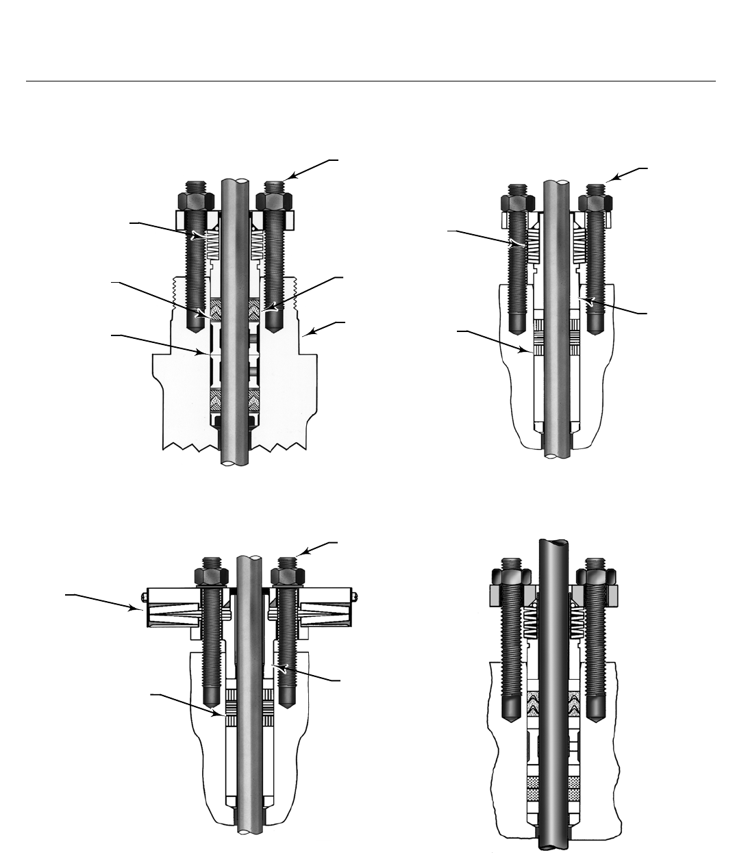
Figure 10. ENVIRO-SEAL and HIGH-SEAL Packing Systems
W7018
W8532-1
FOLLOWER
PACKING
BOX
STUD
PACKING
SPRINGS
W8533-1
PACKING
BOX
STUD
FOLLOWER
PACKING
SPRING
W5803-3
SPRINGS
ANTI-
EXTRUSION
RING
LANTERN
RING
PACKING
BOX
STUDS
PACKING
RING
VALVE
BONNET
TYPICAL ENVIRO-SEAL PACKING SYSTEM
WITH PTFE PACKING
TYPICAL ENVIRO-SEAL PACKING SYSTEM
WITH GRAPHITE ULF PACKING
TYPICAL HIGH-SEAL PACKING SYSTEM
WITH GRAPHITE ULF PACKING
TYPICAL ENVIRO-SEAL PACKING SYS
TEM WITH DUPLEX PACKING
ET Valve
D100022X012
Product Bulletin
51.1:ET
December 2012
15
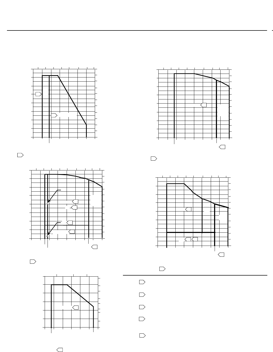
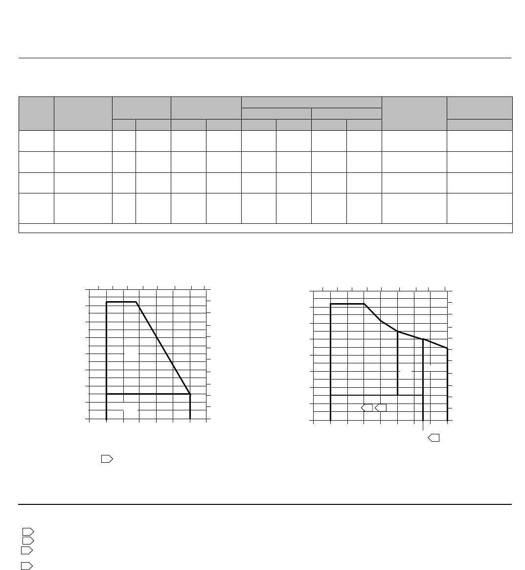
Figure 11. Typical Trim for All Valves Except Those with Cavitrol III, Whisper Trim III, or WhisperFlo Cages
1600
1400
1200
1000
800
600
400
200
0
-200 -100
-20
0 100 200 300 400 500
PRESSURE DROP, PSI
TRIM CAPABILITIES FOR PTFE SEATING
PRESSURE DROP, BAR
110
100
90
80
70
60
50
40
0
30
20
10
FLUID TEMPERATURE, F
- 100 - 50 0 50 100 150 200 250
FLUID TEMPERATURE, C
1600
1400
1200
1000
800
600
400
200
0
-200 -100
-20
0 100 200 300 400 500 600
PRESSURE DROP, PSI
FOR OPTIONAL METAL SEATING
WITH CL600 WCC STEEL, OR WC9 CHROME
MOLY STEEL, BODY
PRESSURE DROP, BAR
110
100
90
80
70
60
50
40
0
30
20
10
FLUID TEMPERATURE, F
- 100 - 50 0 50 100 150 200 250
FLUID TEMPERATURE, C
1600
1400
1200
1000
800
600
400
200
0
- 200 - 100 0 100 200 300 400 500 600
PRESSURE DROP, PSI
FOR OPTIONAL METAL SEATING WITH
CL600 CF8M(316 SST) BODY
PRESSURE DROP, BAR
110
100
90
80
70
60
50
40
0
30
20
10
FLUID TEMPERATURE, F
- 100 - 50 0 50 100 150 200 250
FLUID TEMPERATURE, C
1600
1400
1200
1000
800
600
400
200
0
- 200 - 100
-50
0 100 200 300 400 500 600
PRESSURE DROP, PSI
FOR OPTIONAL METAL SEATING WITH
CL600 LCC STEEL BODY
PRESSURE DROP, BAR
110
100
90
80
70
60
50
40
0
30
20
10
FLUID TEMPERATURE, F
- 100 - 50 0 50 100 150 200 250
FLUID TEMPERATURE, C
500
400
300
200
100
0
-100
-20
0 100 200 300 400
450600
PRESSURE DROP, PSI
FOR OPTIONAL METAL SEATING WITH
CL250B CAST IRON BODY
PRESSURE DROP, BAR
40
35
30
25
20
0
15
10
5
FLUID TEMPERATURE, F
FLUID TEMPERATURE, C
600
300
300
450
300
450
450
2000100
NOTES:
Use trim 27 instead of trim 29 for nonlubricating
fluids such as superheated steam or dry gases
between 149C (300F) and 232C (450F).
Do not exceed the maximum pressure and temperature
for the pressure rating of the body material used,
even though the trims shown may have higher capabilities.
Trims 4 and 29 may be used up to 99 bar (1440 psi) with clean
dry gas. For process fluids other than clean dry gas,
Use trims 4 and 29 only up to 21 bar (300 psi).
Trims 1, 27, and 37H temperature limits can be extended
to 316C(600F)fornon-oxidizingserviceor260C
(500F) oxidizing service if PEEK anti-extrusion rings
are used with spring-loaded seal rings.
Use trim 37H instead of trim 37 for temperatures
above 210C (410F). Requires anti-extrusion rings and
spring-loaded seal rings for temperatures above 232C (450F).
1
2
3
5
4
4C
OR
29C
29COR57C
1OR37 1
OR
37H
1
OR
37H
1OR37
1OR37
1,4 OR 37
28,29
27
27
29
3
3
2
2
5
4
5
5
4
2
3
1
4
2
5
2
3
A6736-2
-20
3
4
4
37
3
ET Valve
D100022X012
Product Bulletin
51.1:ET
December 2012
16
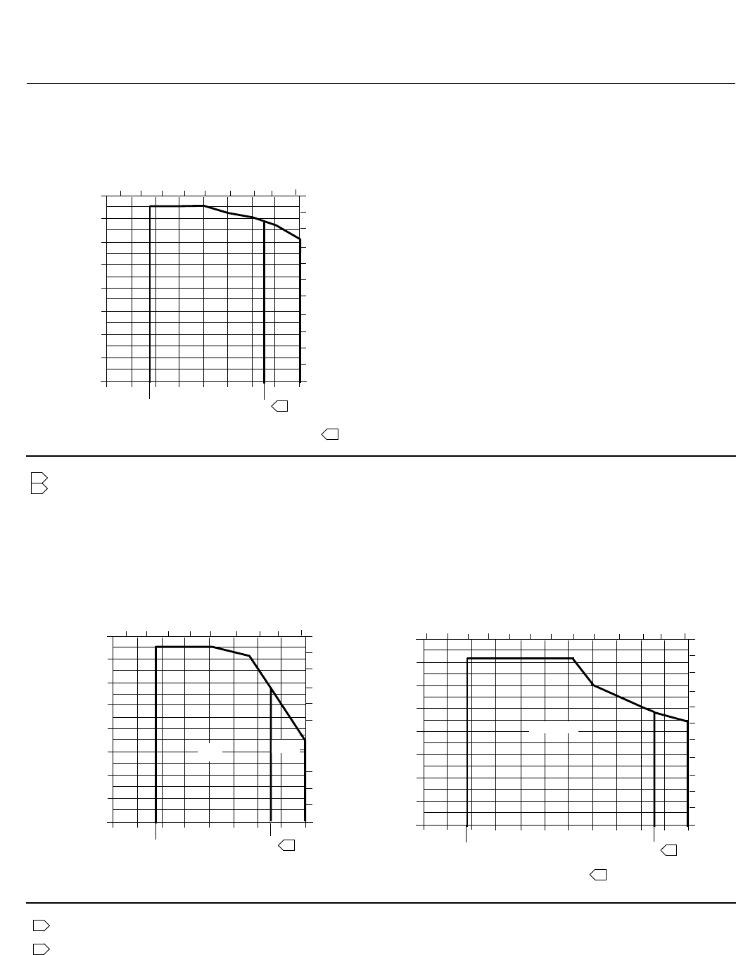
Figure 12. Typical Trim for Cavitrol III Cage Constructions
Notes:
Do not exceed the maximum pressure and temperature for the pressure rating of the bodymaterialused,eventhough the trimshownmay have highercapabilities.
Trim 76 temperature limits can be extended to 316C (600F) for non-oxidizing
service or 260C (500F) for oxidizing service if IF PEEK anti-extrusion rings are used with spring-loaded seal rings.
2
1600
1400
1200
1000
800
600
400
200
0
-200 -100
-20
0 100 200 300 400 500 600
PRESSURE DROP, PSI
WITH STEEL OR STAINLESS STEEL BODIES
PRESSURE DROP, BAR
110
100
90
80
70
60
50
40
0
30
20
10
LIQUID TEMPERATURE, F
- 100 - 50 0 50 100 150 200 250
LIQUID TEMPERATURE, C
300
450 2
1
1
A6737
76
76
Figure 13. Typical Trim for NPS 6 Fisher ET Valve with Whisper Trim III Cage
WITH CL600 WCC STEEL
OR WC9 CHROME MOLY BODY
Notes:
Do not exceed the maximum pressure and temperature for the pressure rating of the body material used, even though the trims shown may have higher
capabilities.
Trims 301 and 312 temperature limits can be extended to316C (600F)for non-oxidizing service or 260C(500F) for oxidizing service if PEEK anti-extrusion rings
are used with spring-loaded seal rings.
1600
1400
1200
1000
800
600
400
200
0
- 200 - 100
-20
0 100 200 300 400 500 600
PRESSURE DROP, PSI
PRESSURE DROP, BAR
110
100
90
80
70
60
50
40
0
30
20
10
FLUID TEMPERATURE, F
- 100 - 50 0 50 100 150 200 250 300
450
2
2
1
1600
1400
1200
1000
800
600
400
200
0
-200 -100
-325
0 100 200 300 400 500 600
PRESSURE DROP, PSI
WITH CL600
316 STAINLESS STEEL (CF8M) BODY
PRESSURE DROP, BAR
110
100
90
80
70
60
50
40
0
30
20
10
FLUID TEMPERATURE, F
- 100 - 50 0 50 100 150 200 250
FLUID TEMPERATURE, C
300
450 2
1
FLUID TEMPERATURE, C
301
301
301C
-400-500
- 200-300
312, 312C
A6738
312

ET Valve
D100022X012
Product Bulletin
51.1:ET
December 2012
17
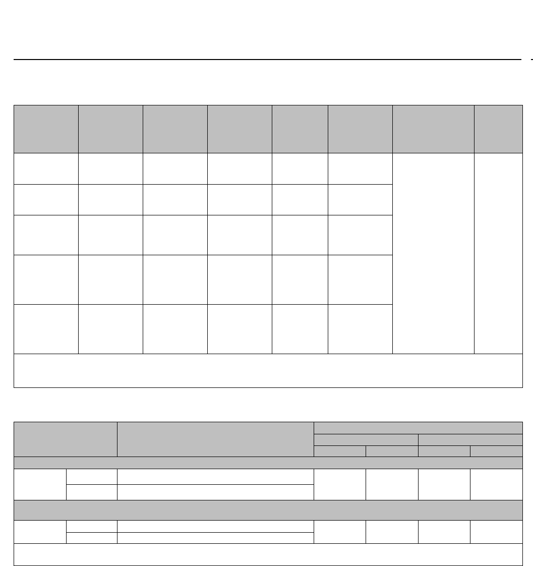
Table 9. Materials and Temperature Limits for Other Parts
PART MATERIAL
TEMPERATURE CAPABILITIES
_C_F
Minimum Maximum Minimum Maximum
Body-to-bonnet
bolting. See
table 18 for
NACE bolting
materials and
temperature
limits
Cast iron body Cap screws Steel SAE Grade 5 -29 232 -20 450
WCC body Studs Steel SA-193-B7 -29
---
(5)
-20
---
(5)
Nuts Steel SA-194-2H
LCC body Studs Steel SA-193-B7 -46 -50
Nuts Steel SA-194-2H
CF8M
(316 stainless
steel) body
Studs Steel SA-193-B7 (std) (NACE [non-exposed
bolting]) -48 ---
(5) -55 ---
(5)
Nuts Steel SA-194-2H (std) (NACE [non-exposed
bolting]) -46 ---
(5) -50 ---
(5)
Studs S30400 stainless steel SA-320-B8 ---
(5) 38 ---
(5) 100
Nuts S30400 stainless steel SA-194-8
Studs
S31600 stainless steel SA-193-B8M
(strain-hardened) or
S31600 stainless steel SA-193-B8M ---
(5) ---
(5) ---
(5) ---
(5)
Nuts S31600 stainless steel SA-194-8M
Disk PTFE -73 204 -100 400
2-piece valve plug seal (standard for
NPS 1 thru 6 valves except those with
Cavitrol III cage)
Backup ring
Fluorocarbon(1) -18 204 0400
Ethylene-propylene(2) -40 232 -40 450
Nitrile(3)
For use with air and
hydrocarbons -40 71 -40 160
For use with other
compatible fluids -40 82 -40 180
Seal ring Carbon-filled PTFE -73 232 -100 450
Spring-loaded valve plug seal(7)
Backup
ring(4)
S41600 stainless steel -29 ---
(5) -20 ---
(5)
S31600 stainless steel
---
(5) ---
(5) ---
(5) ---
(5)
Retaining
ring(4) S30200 stainless steel (N07750, NACE Std)
Seal ring PTFE with N10276 spring -73 232 -100 450
For applications using PEEK
Anti-Extrusion Rings: Spring-loaded
valve plug seal
Backup
ring(4)
S41600 stainless steel -29 ---
(5) -20 ---
(5)
S31600 stainless steel
---
(5) ---
(5) ---
(5) ---
(5)
Retaining
ring(4) S30200 stainless steel
Seal ring PTFE/graphite with R30003spring 232 316(6) 450 600(6)
Anti-extru-
sion rings PEEK (PolyEtherEtherKetone) ---
(5) ---
(5)
Valve plug stem S31600 (S20910, NACE Std.)
---
(5) ---
(5) ---
(5) ---
(5)
Load ring (NPS 8 ET valve only) S17400 or
optional N06600 or N05500
Restricted trim adaptors
Cast iron -73 232 -100 450
WCC steel -29 ---
(5) -20 ---
(5)
S31600 stainless steel ---
(5) ---
(5)
Seat ring, bonnet and cage gaskets FGM (standard) ---
(5) ---
(5)
PTFE-coated N04400 ---
(5) 149 ---
(5) 300
Spiral wound gasket N06600/graphite (FGM-standard) ---
(5) ---
(5)
N04400/PTFE -73 149 -100 300
Shim S31600 stainless steel ---
(5) ---
(5) ---
(5) ---
(5)
N04400
Packing
(temperatures
shown are material
temperature
capabilities)
See table
11 for
proper
bonnet
selection
PTFE V-ring -40 232 -40 450
PTFE/composition -73 232 -100 450
Graphite ribbon/filament ---
(5) ---
(5)
-continued-
ET Valve
D100022X012
Product Bulletin
51.1:ET
December 2012
18
Table 9. Materials and Temperature Limits for Other Parts (continued)
PART MATERIAL
TEMPERATURE CAPABILITIES
_C_F
Minimum Maximum Minimum Maximum
Packing flange, studs, and nuts when used with
standard bonnet S31600 stainless steel ---
(5) ---
(5)
Metal packing box parts S31600 or S17400 stainless steel depending
on part ---
(5) ---
(5)
Extension bonnet bushing Trims 1 & 4 S41600 stainless steel -29 ---
(5) -20 ---
(5)
Other trims S31600 stainless steel ---
(5) ---
(5)
1. For high-temperature air, hydrocarbons, and certain other chemicals and solvents. Not for use with steam or ammonia. Not recommended for water above 82_C (180_F).
2. Has excellent moisture resistance to hot water and steam and may be used with most fire-resistant hydraulic oils, but cannot be used with petroleum-based fluids and other hydrocarbons.
3. Cannot be used with fire-resistant hydraulic oils.
4. These parts not used with 137 mm (7 inch) ports or larger.
5. These materials not limiting factors.
6. This material may be used in temperatures up to 260_C(500_F) for oxidizing service.
7. Standard for NPS 8 valve regardless of cage and all NPS 1 thru 6 valves with Cavitrol III cages, optional in NPS 1 thru 6 valves with other than Cavitrol III cages.
Table 10. Fisher ET Valve Body/Trim Temperature Capabilities For All Valves Except Cavitrol III, NPS 6 ET with Whisper
Trim III Cage, and NPS 4, 6, and 8 ET with WhisperFlo Cage
BODY/BONNET(3)
MATERIALS
TRIM
DESIGNATION VALVE SIZE AND DESIGN
MATERIAL TEMPERATURE CAPABILITY
_C_F
Min Max Min Max
Cast iron
1, 3, 27, 29, or 57 All -29 232 -20 450
37 All -29 210 -20 410
37H All 210 232 410 450
WCC steel
1All -29 316(1) -20 600(1)
27 All -29 316(1) -20 600(1)
29 All -29 149(2) -20 300(2)
37 All -29 210 -20 410
37H All 210 316(1) 410 600(1)
57 All -29 232 -20 450
WC9 chrome moly steel
1or3 All -29 316(1) -20 600(1)
27 All -29 316(1) -20 600(1)
29 All -29 149(2) -20 300(2)
37 All -29 210 -20 410
37H All 210 316(1) 410 600(1)
57 All -29 232 -20 450
LCC steel
1All -29 316(1) -20 600(1)
4All -46 210 -50 410
27 All -46 316(1) -50 600(1)
29 All -46 149(2) -50 300(2)
37 All -46 210 -50 410
37H All 210 316(1) 410 600(1)
57 All -29 232 -20 450
CF8M (316 stainless steel)
27 All -198(4) 316(1) -325(4) 600(1)
28 All -198(4) 149(2) -325(4) 300(2)
29 All -198(4) 149(2) -325(4) 300(2)
1. Temperatures above 232_C (450_F) require PEEK anti-extrusion rings and spring-loaded seal ring. This option allows ET construction to be used up to 316_C (600_F) for non-oxidizing service
and 260_C(500_F) for oxidizing service.
2. Lubricating service allows usage to 232_C(450_F)
3. Same material also used for bottom flange, if required. Restricted trim and full-sized limits are the same.
4. May be used down to -254_C(-425_F) if manufacturing process includes Charpy impact test.

ET Valve
D100022X012
Product Bulletin
51.1:ET
December 2012
19
Table 11. Bonnet Selection Guidelines
BONNET STYLE PACKING MATERIAL IN-BODY PROCESS TEMPERATURE LIMITS(1)
_C_F
Plain:
JStandard for all valve sizes through NPS 6 with
2-13/16 yoke boss diameter
JStandard for NPS 6 and 8 valves in cast iron and WCC
steel bonnet material with 3-9/16 yoke boss diameter
PTFE V-ring -18 to 232 0 to 450
PTFE/Composition -18 to 232 0 to 450
Graphite ribbon/filament 0 to 316(2) 0 to 600(2)
Style 1 Cast Extension:
JStandard for NPS 8 valves in S31600 bonnet material
with 3-9/16 yoke boss diameter
PTFE V-ring
-46 to 316(2) -50 to 600(2)
PTFE/Composition
Graphite ribbon/filament
Style 2 Cast Extension:
JOptional for NPS 2 through 4 valve sizes with 2-13/16
inch yoke boss diameter
JOptionalforNPS6and8valveswith3-9/16 yoke boss
diameter. Not available for NPS 8 valve in S31600
bonnet material
PTFE V-ring
-101 to 316(2) -150 to 600(2)
PTFE/Composition
Graphite ribbon/filament
ENVIRO-SEAL bellows seal bonnet
PTFE
For exceptional stem sealing capabilities. See Bulletin
59.1:070, ENVIRO-SEAL Bellows Seal Bonnets, for
pressure/temperature ratings.
Graphite ULF
For exceptional stem sealing capabilities. See Bulletin
59.1:070, ENVIRO-SEAL Bellows Seal Bonnets, for
pressure/temperature ratings.
1. These in-body process temperatures assume an outside, ambient temperature of 21_C(70_F) and no insulation on the bonnet. When using any packing at low process temperatures, a cast
extension bonnet may have to be used to prevent packing damage which could result from the formation of valve stem frost. Material selection for trim and other components will also be
limiting factors.
2. Temperatures above 232_C (450_F) require PEEK anti-extrusion rings and spring-loaded seal ring.
Table 12. Maximum Flow Coefficients for Full-Sized Trim with Equal Percentage Cage and Normal Flow Direction
Valve Valve Size, NPS Cv at Max. Valve Plug Travel
ET
1
1-1/2
2
2-1/2
3
17.2
35.8
59.7
99.4
136
4
6
8(1)
8(2)
224
394
567
819
EAT
with liner
1
2
3
4
6
18.5
48.1
149
152
336
without liner
1
2
3
4
6
19.0
47.2
148
156
328
ETR
1
1-1/2
2
2-1/2
3
4
17.2
35.8
59.7
99.4
136
224
1. With 51 mm (2 inch) travel.
2. With 76 mm (3 inch) travel.
ET Valve
D100022X012
Product Bulletin
51.1:ET
December 2012
20
Table 13. Port Diameters and Valve Plug Travel
VALVE SIZE, NPS PORT
DIAMETER(1)
MAXIMUM VALVE
PLUG TRAVEL(1)
ET or ETR EAT
Full-Sized Trim Restricted-
Capacity Trim Full-Sized Trim Restricted-
Capacity Trim mm Inch mm Inch
1
---
1-1/2
---
1-1/2
2
---
2-1/2
1
---
2
---
2
---
---
---
33.3
33.3
46.7
46.7
1.3125
1.3125
1.875
1.875
19.1
19.1
19.1
19.1
0.75
0.75
0.75
0.75
2
2-1/2
3
3
4
---
---
3
4
4
6
---
58.7
73.0
87.3
2.3125
2.875
3.4375
29
38
38
1.125
1.5
1.5
4--- 6--- 111.1 4.375 51 2
6(2) --- --- --- 177.8(3) 7(3) 51(3) 2(3)
136.5(4) 5.375(4) 76(4) 3(4)
8(2) --- --- --- 203.2 851 2
76 3
1. For Cavitrol III trim, see table 15.
2. Not available in ETR valves.
3. Standard-travel cages.
4. Whisper Trim III cages
Table14.StemandYokeBossDiameters
VALVE SIZE, NPS STEM AND YOKE BOSS DIAMETERS
ET or ETR EAT Standard Optional
Full-Sized Trim Restricted-
Capacity Trim Full-Sized Trim Restricted-
Capacity Trim
Stem Yoke Boss Stem Yoke Boss
mm Inch mm Inch mm Inch mm Inch
1
---
1-1/2
---
1-1/2
2
---
2-1/2
1
---
2
---
2
---
---
---
9.5
12.7
9.5
12.7
3/8
1/2
3/8
1/2
54
71
54
71
2-1/8
2-13/16
2-1/8
2-13/16
12.7
---
12.7
---
1/2
---
1/2
---
71
---
71
---
2-13/16
---
2-13/16
---
2
2-1/2
3
3
4
---
---
3
4
4
6
---
12.7
12.7
12.7
1/2
1/2
1/2
71
71
71
2-13/16
2-13/16
2-13/16
19.1
19.1
19.1
3/4
3/4
3/4
90
90
90
3-9/16
3-9/16
3-9/16
4--- 6--- 12.7 1/2 71 2-13/16 19.1 3/4 90 3-9/16
25.4 1127 5
6(1) --- --- ---
19.1 3/4 90 3-9/16 25.4 or
31.8
1or
1-1/
4
127 5
8(1) --- --- ---
1. Not available in ETR valves.

ET Valve
D100022X012
Product Bulletin
51.1:ET
December 2012
21
Table 15. Port Diameters and Valve Plug Travel for Cavitrol III Cage
ET
VALVE SIZE, NPS
ONE-STAGE CAGE TWO-STAGE CAGE
Port Diameters Valve Plug Travel(1) Port Diameters Valve Plug Travel
mm
133.3 25 25.4 25
1-1/2 47.6 22 33.3 38
258.7 29 47.6 51
2-1/2 73.0 38 58.7 64
387.3 41 7.30 76
4111.1 54 73.0 102
6177.8 57 136.5 102
8203.2 86 177.8 152
Inch
11.3125 1 1 1
1-1/2 1.875 0.875 1.3125 1.5
22.3125 1.125 1.875 2
2-1/2 2.875 1.5 2.3125 2.5
33.4375 1.625 2.875 3
44.375 2.125 2.875 4
6 7 2.25 5.375 4
8 8 3.375 7 6
1. The travel listed is the maximum travel that can be obtained for the given size. In situations where increased valve capacity is not needed, standard ET valve travels should be utilized in
selecting the actuator.
ET Valve
D100022X012
Product Bulletin
51.1:ET
December 2012
22
Table 16. Port Diameters, Valve Plug Travel, Yoke Boss Diameters for TSO (Tight Shutoff) Trim
VALVE TRIM MAX TRAVEL YOKE BOSS SIZE PORT DIAMETER CVREDUCTION
AT 100%
TRAVEL(1)
UNBALANCE
AREA
Nominal Actual TSO
mm Inch mm Inch mm Inch mm Inch Inch2
ET
NPS 3 CAV III 2-Stage 76.2 390
127
3-9/16
573.0 2.875 68.3 2.6875 0% 0.098
ET
NPS 4 CAV III 2-Stage 102 490
127
3-9/16
573.0 2.875 68.3 2.6875 5% 0.098
EAT
NPS 4 Std 38.1 1.5 71.4
90
2-13/16
3-9/16 87.3 3.4375 82.6 3.25 6%
4% 0.118
EAT
NPS 6 Std 50.8 290 3-9/16 111 4.375 106 4.1875
4% (linear)
3% (equal
percent)
0.154
1. This column lists the percent reduction of published maximum CVof the trim listed in the TRIM column.
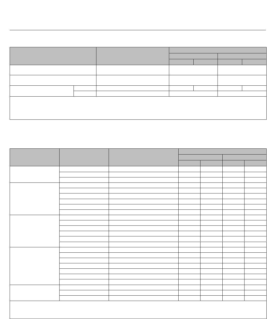
Figure 14. Typical Trim for NACE MR0175 / ISO 15156 and MR0103 (Sour Service)
1600
1400
1200
1000
800
600
400
200
0
- 200 - 100 0 100 200 300 400 500
PRESSURE DROP, PSI
FOR STANDARD PTFE SEATING WITH
ALL BODY MATERIALS
PRESSURE DROP, BAR
110
100
90
80
70
60
50
40
0
30
20
10
FLUID TEMPERATURE, F
- 100 - 50 0 50 100 150 200 250
FLUID TEMPERATURE, C
1600
1400
1200
1000
800
600
400
200
0
- 200 - 100 0 100 200 300 400 500 600
PRESSURE DROP, PSI
PRESSURE DROP, BAR
110
100
90
80
70
60
50
40
0
30
20
10
FLUID TEMPERATURE, F
- 100 - 50 0 50 100 150 200 250
FLUID TEMPERATURE, C
300
450
86
2
3
4
87C
85C
87
85 1
FOR OPTIONAL METAL SEATING WITH
ALL BODY MATERIALS
Notes:
Use trim 87 instead of trim 85 for nonlubricating fluids such as super-heated steam or dry gases between 149C (300F) and 232C (450F).
Donot exceedthe maximum pressureandtemperatureforthe pressureratingofthe bodymaterialused,eventhoughthetrimsshown mayhave highercapabilities.
Trim 85 may be used up to 99 bar (1440 psi) with clean dry gas. For process fluids other than clean dry gas, use trim 85 only up to
21 bar (300 psi).
Trim 87 temperature limits can be extended to 316C(600F) for non-oxidizing service or 260C (500F) for oxidizing service if PEEK anti-extrusion rings are used
with spring-loaded seal rings.
1
2
3
4
A6739-1
87
ET Valve
D100022X012
Product Bulletin
51.1:ET
December 2012
23
Table 17. Metal Trim Part Materials for Compatibility with NACE MR0175 / ISO 15156 and MR0103 (Sour Service)
Specifications. Environmental Restrictions Apply, Refer to Standard.
Trim
Designation(4) Valve Plug Cage
Seat Ring
for Standard
Metal Seat
Construction
Optional
Liner
for Metal
Seat
(EAT only)
Disk Seat and
Retainer for
Optional
PTFE-Seat
Construction
Valve Stem, Packing
Follower, Lantern
Ring, Packing Box
Ring, and Pin
Load
Ring(1)
85(5) S31600
S31600 with
electroless nickel
coating (ENC)
S31600 S31600 ---
S20910 (Valve Stem)
S31600 (All Other
Parts)
N05500
85C(2, 5) S31600
S31600 with
electroless nickel
coating (ENC)
--- --- S31600
86(5)
S31600 with seat
hard faced with
CoCr-A
hardfacing alloy
S31600 with
electroless nickel
coating (ENC)
R30006 (alloy 6) --- ---
87
(Also used for
8-inch Whisper
Trim I)
S31600 with seat
and guide hard
faced with
CoCr-A
hardfacing alloy
S31600 with
electroless nickel
coating (ENC)(3)
R30006 (alloy 6) --- ---
87C(2)
(Also used
for 8-inch
Whisper Trim I)
S31600 with seat
and guide hard
faced with
CoCr-A
hardfacing alloy
S31600 with
electroless nickel
coating (ENC)(3)
--- --- S31600
1. NPS 8 valve body only.
2. 85C and 87C are trims for PTFE-seat construction.
3. 8-inch Whisper Trim I cage is CB7CU-1, double H1150 (NACE) / ENC.
4. N07750 retaining ring is standard for spring-loaded seal ring construction.
5. Not for use with Whisper Trim I with 136 mm (5.375 inch) and larger ports.
Table 18. Bolting Materials and Temperature Limits for Bolting Compliance with NACE MR0175-2002, NACE
MR0175/ISO 15156, and NACE MR0103. Environmental restrictions may apply
VALVE BODY MATERIAL BOLTING MATERIAL
TEMPERATURE CAPABILITIES
_C_F
Min Max Min Max
Non-exposed bolting (Standard)
WCC and
CF8M
(316 SST)
Studs Steel SA-193-B7
-48(2) 427 -55(2) 800
Nuts Steel SA-194-2H
Exposed bolting (Optional)
May require derating of valve(1) when these body-to-bonnet bolting materials are used
WCC and
CF8M
Studs Steel SA-193-B7M -48(2) 427 -55(2) 800
Nuts Steel SA-194-2HM
1. Derating is not required for CL150 and 300 valves. Derating may be required for valves rated at CL600. Contact your Emerson Process Management sales office for assistance in determining
the derating of valves when these body-to-bonnet bolting materials are used.
2. -29_C(-20_F) with WCC body material.
ET Valve
D100022X012
Product Bulletin
51.1:ET
December 2012
24
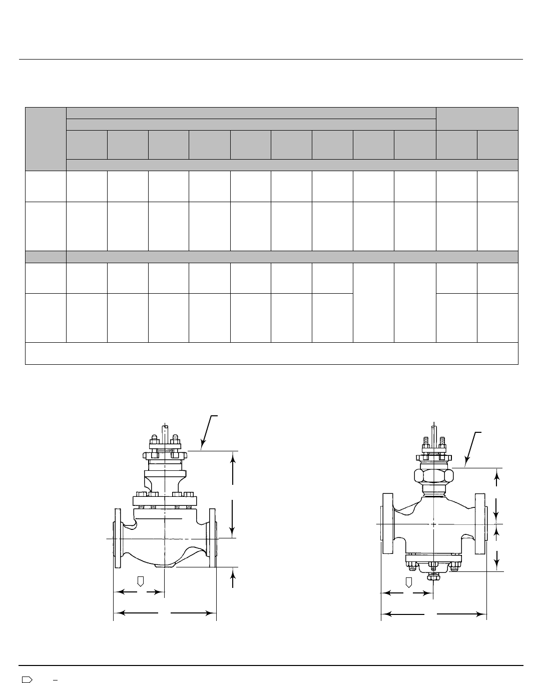
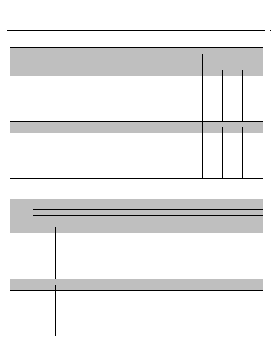
Table 19. Fisher ET and ETR Dimensions
VALVE
SIZE, NPS
AG(MAX)
Pressure Rating, End Connection Style (1)
Scrd or
SW
CL125 FF
or
CL150 RF
CL150
RTJ
CL250 RF
or
CL300 RF
CL300
RTJ
BW or
CL600 RF
CL600
RTJ
PN16-40(
2)
PN63-100
(2) ET ETR
mm
1
1-1/2
2
210
251
286
184
222
254
197
235
267
197
235
267
210
248
282
210
251
286
210
251
289
160
200
230
230
260
300
60
71
78
119
116
133
2-1/2
3
4
6
8
---
---
---
---
---
276
298
353
451
543
292
311
365
464
556
292
317
368
473
568
308
333
384
489
584
311
337
394
508
610
314
340
397
511
613
290
310
350
480
600
340
380
430
550
650
90
97
129
140
191
159
168
192
---
---
Inch
1
1-1/2
2
8.25
9.88
11.25
7.25
8.75
10.00
7.75
9.25
10.50
7.75
9.25
10.50
8.25
9.75
11.12
8.25
9.88
11.25
8.25
9.88
11.38 See
mm
above
See
mm
above
2.38
2.81
3.06
4.69
4.56
5.25
2-1/2
3
4
6
8
---
---
---
---
---
10.88
11.75
13.88
17.75
21.38
11.38
12.25
14.38
18.25
21.88
11.50
12.50
14.50
18.62
22.38
12.12
13.12
15.12
19.25
23.00
12.25
13.25
15.50
20.00
24.00
12.38
13.38
15.62
20.12
24.12
3.56
3.81
5.06
5.51
7.50
6.25
6.62
7.56
---
---
1. End connection style abbreviations: BW -Buttwelding, FF -Flat Faced, Scrd -Screwed, SW -Socketweld, RF -Raised Face, RTJ -Ring Type Joint
2. Valves which meet EN 1092 flange standards and have EN face-to-face dimensions are available only from Europe (EN 558-1). Valves which meet EN 1092 flange standards but not EN
face-to-face standards are available in the US. Consult your Emerson Process Management sales office.
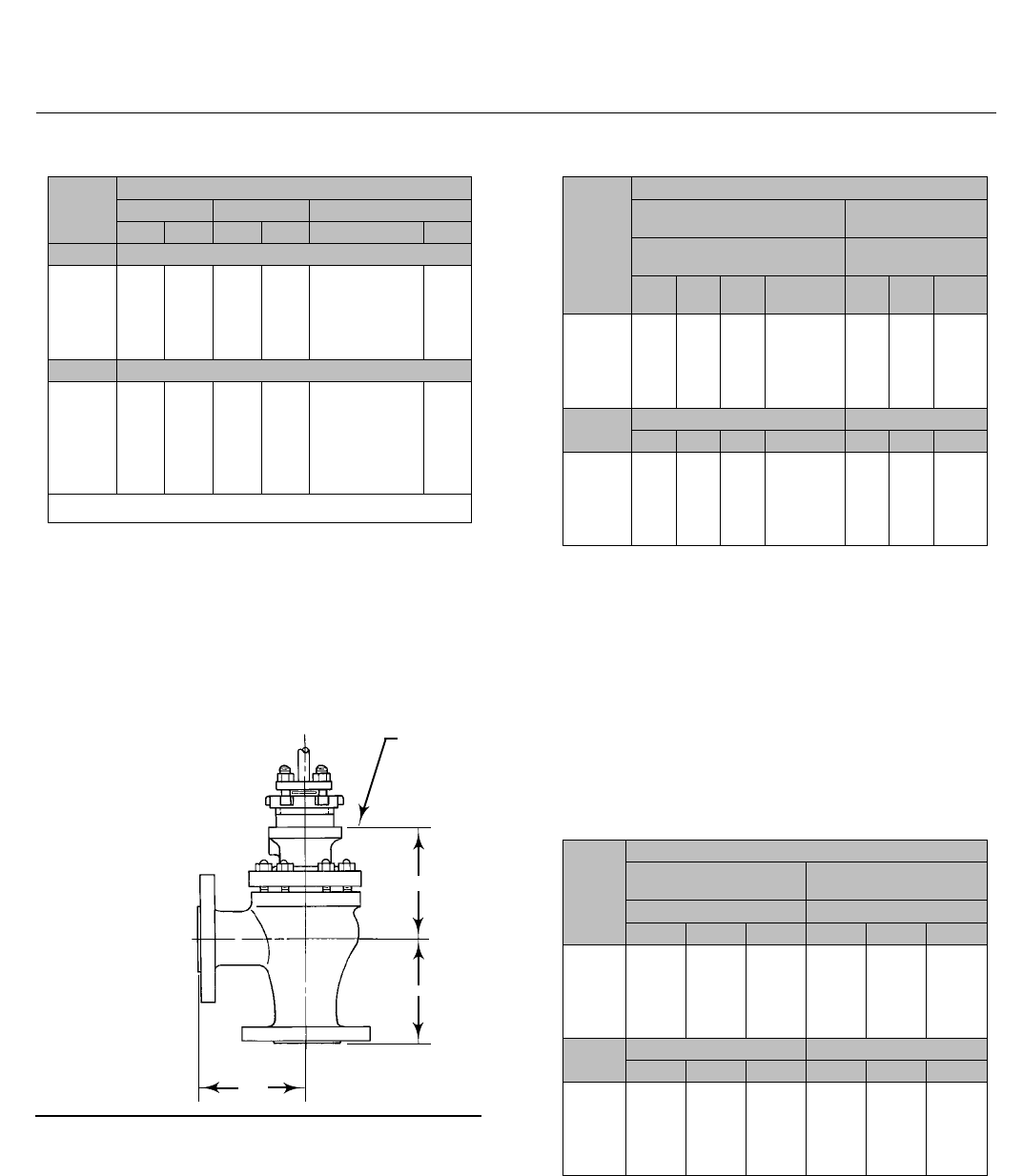
Figure 15. Fisher ET and ETR Dimensions (also see tables 19, 20, and 21)
2. For dimensions of valves with other end connections, consult your Emerson sales office.
A
G
D
MATCH LINE
FOR
ACTUATOR
1
1
B
AR4967-a
A0925-3
Notes:
B=A
2
ET CONTROL VALVE
B
A
G
D
MATCH
LINE
FOR
ACTUATOR
1
10A7397-B
A0926-2 ETR CONTROL VALVE
ET Valve
D100022X012
Product Bulletin
51.1:ET
December 2012
25
Table 20. Fisher ET and ETR Dimensions
VALVE
SIZE,
NPS
D FOR PLAIN BONNET
ET Except
with Cavitrol III Two-Stage Cage
ET
with Cavitrol III Two-Stage Cage ETR
Stem Diameter, mm Stem Diameter, mm Stem Diameter, mm
9.5 12.7 19.1 25.4 or 31.8 9.5 12.7 19.1 25.4 or 31.8 9.5 12.7 19.1
1
1-1/2
2
2-1/2
3
127
124
---
---
---
149
146
165
187
191
---
---
162
184
187
---
---
---
---
---
---
155
---
---
---
184
177
201
229
260
---
---
198
226
256
---
---
---
---
---
113
122
---
---
---
124
133
148
157
167
---
---
140
152
159
4
6(1)
6(2)
8
---
---
---
---
221
---
---
---
217
251
312
375(3)
264
270
330
426
---
---
---
---
311
---
---
---
308
336
---
511
354
380
---
560
---
---
---
---
198
---
---
---
191
---
---
---
Stem Diameter, Inch Stem Diameter, Inch Stem Diameter, Inch
3/8 1/2 3/4 1or1-1/4 3/8 1/2 3/4 1or1-1/4 3/8 1/2 3/4
1
1-1/2
2
2-1/2
3
5.00
4.88
---
---
---
5.88
5.75
6.50
7.38
7.50
---
---
6.38
7.25
7.38
---
---
---
---
---
---
6.09
---
---
---
7.25
6.97
7.91
9.03
10.22
---
---
7.78
8.91
10.09
---
---
---
---
---
4.44
4.81
---
---
---
4.88
5.25
5.81
6.31
6.56
---
---
5.50
6.00
6.25
4
6(1)
6(2)
8
---
---
---
---
8.69
---
---
---
8.56
9.88
12.26
14.75(3)
10.38
10.62
13.00
16.75
---
---
---
---
12.25
---
---
---
12.12
13.22
---
20.12
13.94
14.97
---
22.06
---
---
---
---
7.81
---
---
---
7.50
---
---
---
1. All except Whisper Trim III and WhisperFlo cages.
2. Whisper Trim III and WhisperFlo cages.
3. Available only in cast iron or WCC steel for the stem diameter with plain bonnet.
Table 21. Fisher ET and ETR Dimensions
VALVE
SIZE, NPS
D FOR EXTENSION AND ENVIRO-SEAL BELLOWS SEAL BONNETS
(ET ONLY, EXCEPT WITH CAVITROL III CAGE)
Style 1 Ext. Bonnet Style 2 Ext. Bonnet ENVIRO-SEAL Bellows Seal Bonnet
Stem Diameter Stem Diameter Stem diameter
mm
9.5 12.7 19.1 25.4 or 31.8 9.5 12.7 19.1 9.5 12.7 19.1
1
1-1/2
2
2-1/2
3
213
210
---
---
---
251
248
267
289
292
---
---
272
294
297
---
---
---
---
---
303
300
---
---
---
319
316
465
492
495
---
---
---
---
487
320
317
---
---
---
---
---
384
---
517
---
---
---
---
517
4
6(1)
6(2)
8
---
---
---
---
322
---
---
---
327
357
418
421
370
402
462
450
---
---
---
---
526
---
---
---
518
543
604
621
---
---
---
---
541
---
---
---
---
573
---
703
Inch
3/8 1/2 3/4 1or1-1/4 3/8 1/2 3/4 3/8 1/2 3/4
1
1-1/2
2
2-1/2
3
8.38
8.25
---
---
---
9.88
9.75
10.50
11.38
11.50
---
---
10.69
11.56
11.69
---
---
---
---
---
11.94
11.81
---
---
---
12.56
12.44
18.31
19.38
19.50
---
---
---
---
19.19
12.62
12.50
---
---
---
---
---
15.12
---
20.38
---
---
---
---
20.38
4
6(1)
6(2)
8
---
---
---
---
12.69
---
---
---
12.88
14.06
16.44
16.56
14.56
15.81
18.19
17.75
---
---
---
---
20.69
---
---
---
20.38
21.38
23.76
24.44
---
---
---
---
21.31
---
---
---
---
22.56
---
27.69
1. Standard-travel cages.
2. Whisper Trim III and WhisperFlo cages.
ET Valve
D100022X012
Product Bulletin
51.1:ET
December 2012
26
Table 22. Fisher EAT Dimensions(1)
VALVE
SIZE,
NPS
AA
CL150 CL300 CL600
RF RTJ RF RTJ BW, SW or RF RTJ
mm
1
2
3
4
6
92
127
149
176
225
98
133
156
183
232
98
133
159
184
237
105
141
167
197
244
105
143
168
197
254
105
144
170
198
256
Inch
1
2
3
4
6
3.62
5.00
5.88
6.94
8.88
3.88
5.25
6.12
7.19
9.12
3.88
5.25
6.25
7.25
9.31
4.12
5.56
6.56
7.56
9.62
4.12
5.62
6.62
7.75
10.00
4.12
5.69
6.69
7.81
10.0
6
1. End connection style abbreviations: BW -Buttwelding, FF -Flat Faced, Scrd -
Screwed, SW -Socketweld, RF -Raised Face, RTJ -Ring Type Joint.
Figure 16. Fisher EAT Dimensions (also see tables 22,
23, and 24)
Note:
For dimensions of valves with PN (or other) end connections, consult your
Emerson sales office.
DD
AA
AA
A0927-2
MATCH LINE
FOR
ACTUATOR
Table 23. Fisher EAT Dimensions
VALVE
SIZE,
NPS
DD
Plain Bonnet Style 1 Extension
Bonnet
Stem Diameter, mm Stem Diameter,
mm
9.5 12.7 19.1 25.4 or
38.1 9.5 12.7 19.1
1
2
3
4
6
111
98
---
---
---
133
121
149
140
144
---
---
146
137
141
---
---
---
---
187
197
184
---
---
---
253
223
251
241
246
---
---
256
246
251
Stem Diameter, In. Stem Diameter, In.
3/8 1/2 3/4 1or1-1/4 3/8 1/2 3/4
1
2
3
4
6
4.38
3.88
---
---
---
5.25
4.75
5.88
5.50
5.69
---
---
5.75
5.38
5.56
---
---
---
---
7.38
7.75
7.25
---
---
---
9.95
8.75
9.88
9.50
9.69
---
---
10.06
9.69
9.88
Table 24. Fisher EAT Dimensions
VALVE
SIZE,
NPS
DD
Style 2 Extension Bonnet ENVIRO-SEAL
Bellows Seal Bonnet
Stem Diameter, mm Stem Diameter, mm
9.5 12.7 19.1 9.5 12.7 19.1
1
2
3
4
6
291
278
---
---
---
305
291
454
445
449
---
---
---
437
441
305
292
---
---
---
---
---
---
467
465
---
---
---
---
---
Stem Diameter, In. Stem Diameter, In.
3/8 1/2 3/4 3/8 1/2 3/4
1
2
3
4
6
11.44
10.94
---
---
---
12.00
11.44
17.88
17.50
17.69
---
---
---
17.19
17.38
12.00
11.50
---
---
---
---
---
---
18.38
18.31
---
---
---
---
---

ET Valve
D100022X012
Product Bulletin
51.1:ET
December 2012
27
Ordering Information
Inlet pressure and temperature must always be limited
by the applicable ASME pressure/temperature rating.
Pressure drop information for various trim material
combinations is provided in figures 11, 12, and 14. The
maximum allowable pressure drop for the application
must not exceed the lowest value indicated for the
combination of materials selected.
When ordering, specify:
Application Information
1. Type of application:
a. Throttling or on-off
b. Reducing or relief
2. Controlled fluid (include chemical analysis of fluid if
possible)
3. Specific gravity of controlled fluid
4. Fluid temperature
5. Inlet pressures:
a. Minimum
b. Normal
c. Maximum
6. Pressure drops:
a. Minimum flowing drop
b. Normal flowing drop
c. Maximum flowing drop
d. Maximum at shutoff
7. Flow rates:
a. Minimum controlled flow
b. Normal flow
c. Maximum flow
8. Maximum permissible noise level, if critical
9. Shutoff classification required
10. Valve stem diameter and bonnet type (plain,
extension, or ENVIRO-SEAL bellows seal bonnet)
11. Linesizeandschedule
Valve Information
To determine what valve ordering information is
needed, refer to the specifications. Review the
description for each specification and in the referenced
tables; write down your choice whenever there is a
selection to be made. Always specify the valve design
letter designation.
Actuator and Accessory Information
Refer to the specific actuator and accessory bulletins
for required ordering information.

ET Valve
D100022X012
Product Bulletin
51.1:ET
December 2012
28
Emerson Process Management
Marshalltown, Iowa 50158 USA
Sorocaba, 18087 Brazil
Chatham, Kent ME4 4QZ UK
Dubai, United Arab Emirates
Singapore 128461 Singapore
www.Fisher.com
The contents of this publication are presented for informational purposes only, and while every effort has been made to ensure their accuracy, they arenot
to be construed as warranties or guarantees, express or implied, regarding the products or services described herein or their use or applicability. All sales are
governed by our terms and conditions, which are available upon request. We reserve the right to modify or improve the designs or specifications of such
products at any time without notice.
E2012 Fisher Controls International LLC. All rights reserved.
Fisher, Cavitrol, easy-e, ENVIRO-SEAL, Whisper Trim, and WhisperFlo are marks owned by one of the companies in the Emerson Process Management
business unit of Emerson Electric Co. Emerson Process Management, Emerson, and the Emerson logo are trademarks and service marks of Emerson Electric
Co. All other marks are the property of their respective owners.
Neither Emerson, Emerson Process Management, nor any of their affiliated entities assumes responsibility for the selection, use or maintenance
of any product. Responsibility for proper selection, use, and maintenance of any product remains solely with the purchaser and end user.
