Emerson Fisher Fieldvuedvc2000 Digital Valve Controller Quick Start Manual
2015-03-30
: Emerson Emerson-Fisher-Fieldvuedvc2000-Digital-Valve-Controller-Quick-Start-Manual-681720 emerson-fisher-fieldvuedvc2000-digital-valve-controller-quick-start-manual-681720 emerson pdf
Open the PDF directly: View PDF ![]() .
.
Page Count: 40
www.Fisher.com
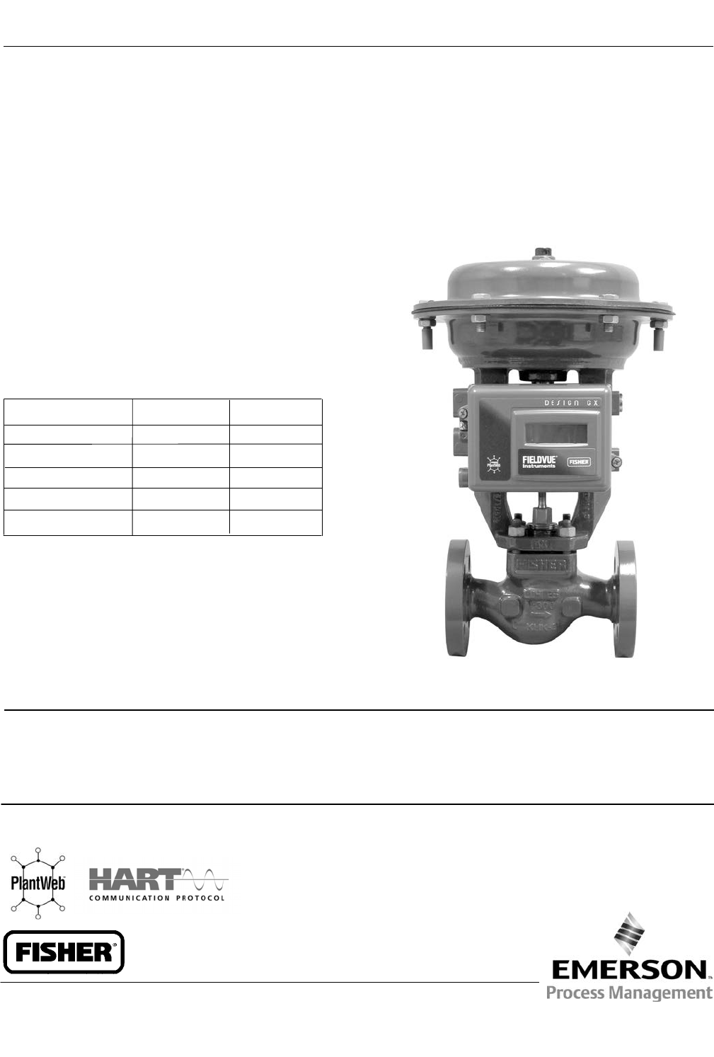
Fisher FIELDVUE™ DVC2000 Digital Valve
Controller
Quick Start Guide
D103203X012
DVC2000 Digital Valve Controller
April 2014
Note
This guide provides installation, initial setup, and calibration information for the DVC2000 digital valve controller. See the
FIELDVUE DVC2000 Digital Valve Controller Instruction Manual (D103176X012), available from your Emerson Process
Management sales office, for additional information, or visit our website at www.FIELDVUE.com.
Instrument Level
Device Type
Device Revision
Hardware Revision
Firmware Revision
DD Revision
Contents
Using this Guide 4..............................
Installation 5..................................
Basic Setup and Calibration 18....................
Specifications 29...............................
Related Documents 32..........................
Hazardous Area Approvals and Special Instructions
Instructions for “Safe Use”and Installations
in Hazardous Locations 33.....................
HC, AD, PD
5
1
1 & 2
1, 2, 3, 4 & 5
3
W8861
AC
5
1
1 & 2
1, 2, 3, 4 & 5
1
Quick Start Guide
D103203X012
DVC2000 Digital Valve Controller
April 2014
2
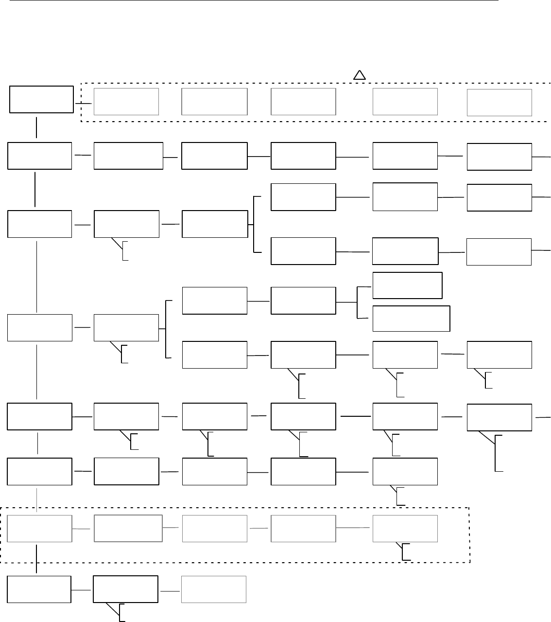
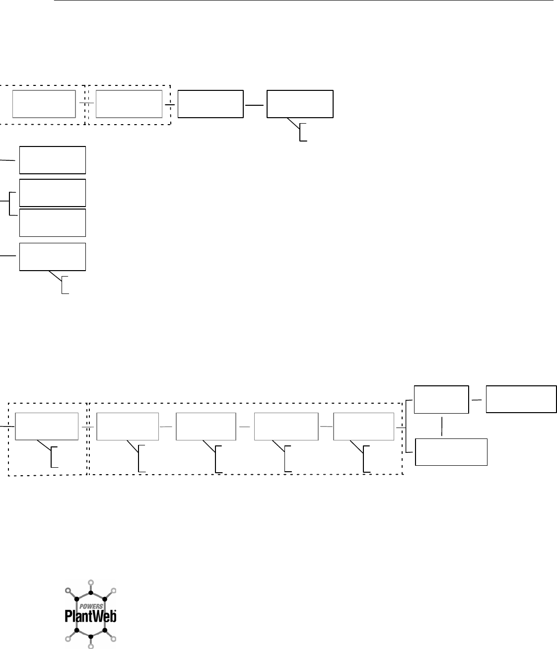
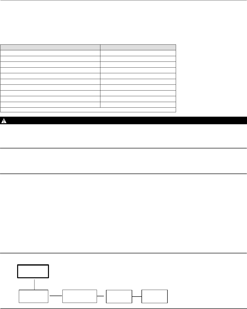
Local Interface Flow Chart
TRAVEL = 66.8%
14.6 MA 0.92 BAR
QUICK SETUP
Y
B
Y
Y
B
B
Y
B
B
Y
Y
Y
B
B
TRAVEL
DEVIATION
CHECK
MOUNTING
CHECK
SUPPLY
CHECK I/P
CONVERTER
VALVE WILL MOVE
PRESS FOR 3 SEC FINDING 0% ... FINDING 100% ... FINDING 50% ...FINDING 0% ...
VALVE WILL MOVE
PRESS FOR 3 SEC
FINDING 100% ... FINDING 0% ... FINDING 50% ...
FINDING 50% ...
TRAVEL
CALIBRATION
TUNING
DETAILED SETUP
ANALOG INPUT
CALIBRATION
POSITION
TRANSMITTER CAL
LOCAL
CONTROL
VALVE WILL MOVE
PRESS FOR 3 SEC
VALVE WILL MOVE
PRESS FOR 3 SEC
YYYYY
YY
Y
Y
Y
Y
Y
Y
Y
Y
Y
Y
Y
Y
YY
YY
Y
Y
Y
Y
Y
Y
Y
Y
Y
YY
ZERO CTL SIGNAL
VALVE CLOSED
PRESSURE UNITS
BAR
INPUT RANGE
LOW 4 mA
INPUT RANGE
HIGH 20 mA
CHARACTERISTIC
LINEAR
SAVE AND EXIT?
PRESS
SAVE AND EXIT?
PRESS
SAVE AND EXIT?
PRESS
Y
MOVE VALVE TO
0% TRAVEL
Y
MOVE VALVE TO
100% TRAVEL
CALIBRATION
AUTOMATIC
YYYY
Y
Y
TUNING
AUTOMATIC
AUTOTUNING IN
PROGRESS...
TUNING
C
APPLY 4 mA
THEN PRESS
APPLY 20 mA
THEN PRESS
VALVE MAY MOVE
PRESS FOR 3 SEC
SHUTDOWN
ACTIVATED
AUTOTUNING
COMPLETE
AUTOTUNING FAILED
USE MANUAL TUNING
DAMPING
NEUTRAL
mA OUT WILL CHANGE
PRESS FOR 3 SEC USE OR
TO SEND 4 mA
USE OR
TO SEND 20 mA
CONTROL
ANALOG
MANUAL SP = XXX
TRAVEL = XXX
Y
Y
Y
Y
Y
Y
Y
Y
Y
ANALOG OR DIGITAL
MANUAL
Y
SAVE AND EXIT? EXIT
W/O SAVING?
SAVE AND EXIT?
EXIT W/O SAVING?
SAVE AND EXIT?
EXIT W/O SAVING?
+5
NEUTRAL
-5
EXPERT,
C,D,E,F,G
H,I,J,K,L,M
AUTOMATIC
MANUAL
BAR
PSI
KPA
CLOSED
OPEN
4 mA
...
19 mA
5 mA
...
20 mA
QUICK OPEN
LINEAR
EQUAL %
CUSTOM
AUTOMATIC
MANUAL
1
2
3
4
5
6
7
8
1
1
1
1
1
These items are identified by an alert icon on the default screen !
Only when transmitter / limit switch hardware is installed.
Y
Home Screen
MANUAL AUTO
MANUAL AUTO
Quick Start Guide
D103203X012
DVC2000 Digital Valve Controller
April 2014
3
Y
Y
Y
Y
Y
Y
Y
Y
Y
Y
Y
Y
Y
VALVE MAY MOVE
PRESS FOR 3 SEC
SAVE AND EXIT?
PRESS
EXIT W/O SAVING?
PRESS
SWITCH2 CLOSED
BELOW 10%
Y
Y
Y
Y
SWITCH1 CLOSED
ABOVE 90%
SWITCH2
TRIP POINT 10%
SWITCH1
TRIP POINT 90%
125%
...
-25%
125%
...
-25%
ABOVE
BELOW
DISABLED
BELOW
ABOVE
DISABLED
TRANSMITTER
4 mA CLOSED
CLOSED
OPEN
Only when transmitter / limit switch hardware is installed
Only when transmitter / limit
switch hardware is installed.
1
1
1
1
1
1
1
Y
Y
Y
QUICK SETUP
COMPLETE
SAVE AND EXIT?
PRESS
SAVE AND EXIT? EXIT
W/O SAVING?
CALIBRATION
COMPLETE
CALIBRATION
FAILED
PROTECTION
OFF
OFF
ON
FW3:1, HW1:2
TUNING = C
Y
Y
Y
Y
Only when transmitter / limit switch
hardware is installed
SWITCH1 = OPEN
SWITCH 2 = CLOSED
REPLACE MAIN
BOARD
+ + +
LANGUAGE SELECTION
+
CANCEL
(TAKES YOU TO THE HOME SCREEN)
Note: Hold + + +
for 3 to 10 seconds
Note: Hold + for 3 to 10 seconds
+
INVERT DISPLAY 180
Note: Hold + for 3 to 10 seconds
Y
Y
THE FIELDVUE DVC2000 DIGITAL VALVE CONTROLLER IS A CORE COMPONENT OF THE PLANTWEB™ DIGITAL PLANT
ARCHITECTURE. THE DIGITAL VALVE CONTROLLER POWERS PLANTWEB BY CAPTURING AND DELIVERING VALVE
DIAGNOSTIC DATA. COUPLED WITH VALVELINK™ SOFTWARE, THE DVC2000 PROVIDES USERS WITH AN ACCURATE
PICTURE OF VALVE PERFORMANCE, INCLUDING ACTUAL STEM POSITION, INSTRUMENT INPUT SIGNAL AND PNEUMATIC
PRESSURE TO THE ACTUATOR. USING THIS INFORMATION, THE DIGITAL VALVE CONTROLLER DIAGNOSES NOT ONLY
ITSELF, BUT ALSO THE VALVE AND ACTUATOR TO WHICH IT IS MOUNTED.

Quick Start Guide
D103203X012
DVC2000 Digital Valve Controller
April 2014
4
Use of this Guide
This guide describes how to install the digital valve controller and setup and calibrate using the local operator
interface. The interface consists of a liquid crystal display, four pushbuttons, and a switch for position transmitter
configuration. The DVC2000 is supplied with one of three different language packs preinstalled, depending on the
firmware revision and ordering option. Language pack options are shown in table 1. To configure the language, follow
the procedure outlined in the Basic Setup section. The instrument must be powered with at least 8.5 volts and 3.5 mA
to operate the local interface. Certain procedures require up to 20 mA of current.
You can also setup and calibrate the instrument using a Field Communicator, a personal computer with ValveLink
software or AMS Suite: Intelligent Device Manager. For information on using the software with a FIELDVUE instrument,
refer to the appropriate user guide or help.
Additional information for installing, operating, and maintaining the DVC2000 digital valve controller can be found in
the related documents listed on page 32.
Do not install, operate, or maintain a DVC2000 digital valve controller without being fully trained and qualified in
valve, actuator, and accessory installation, operation, and maintenance. To avoid personal injury or property damage,
it is important to carefully read, understand, and follow all contents of this quick start guide, including all safety
cautions and warnings. Refer to Hazardous Area Approvals and Special Instructions for “Safe Use” and Installations in
Hazardous Locations, on page 33, for approval specific safe use information. If you have any questions about these
instructions, contact your Emerson Process Management sales office before proceeding.
Quick Start Guide
D103203X012
DVC2000 Digital Valve Controller
April 2014
5
Installation
Note
The DVC2000 is not designed to correct for significant stem rotation on sliding stem actuators.
WARNING
Avoid personal injury or property damage from sudden release of process pressure or bursting of parts. Before mounting
the DVC2000 digital valve controller:
D Always wear protective clothing, gloves, and eyewear when performing any installation procedures.
D Do not remove the actuator from the valve while the valve is still pressurized.
D Disconnect any operating lines providing air pressure, electric power, or a control signal to the actuator. Be sure the
actuator cannot suddenly open or close the control valve.
D Use bypass valves or completely shut off the process to isolate the control valve from process pressure. Relieve process
pressure from both sides of the control valve.
D Use lock‐out procedures to be sure that the above measures stay in effect while you work on the equipment.
D Check with your process or safety engineer for any additional measures that must be taken to protect against process
media.
D Vent the pneumatic actuator loading pressure and relieve any actuator spring precompression so the actuator is not
applying force to the valve stem; this will allow for the safe removal of the stem connector.
WARNING
This product is intended for a specific range of application specifications, found in the Specifications table on page 29.
Incorrect configuration of a positioning instrument could result in the malfunction of the product, property damage or
personal injury.
Note
Refer to Hazardous Area Approvals and Special Instructions for “Safe Use" and Installations in Hazardous Locations,
on page 33, for approval specific safe use and installation information.
Valve / Actuator Mounting
If ordered as a part of a control valve assembly, the factory will mount the digital valve controller on the actuator and
calibrate the instrument. If you purchased the digital valve controller separately, you will need a mounting kit to
mount the digital valve controller on the actuator. The following procedures are general guidelines you should
consider when mounting the digital valve controller. See the instructions that come with the mounting kit for detailed
information on mounting the digital valve controller to a specific actuator model.
Quick Start Guide
D103203X012
DVC2000 Digital Valve Controller
April 2014
6
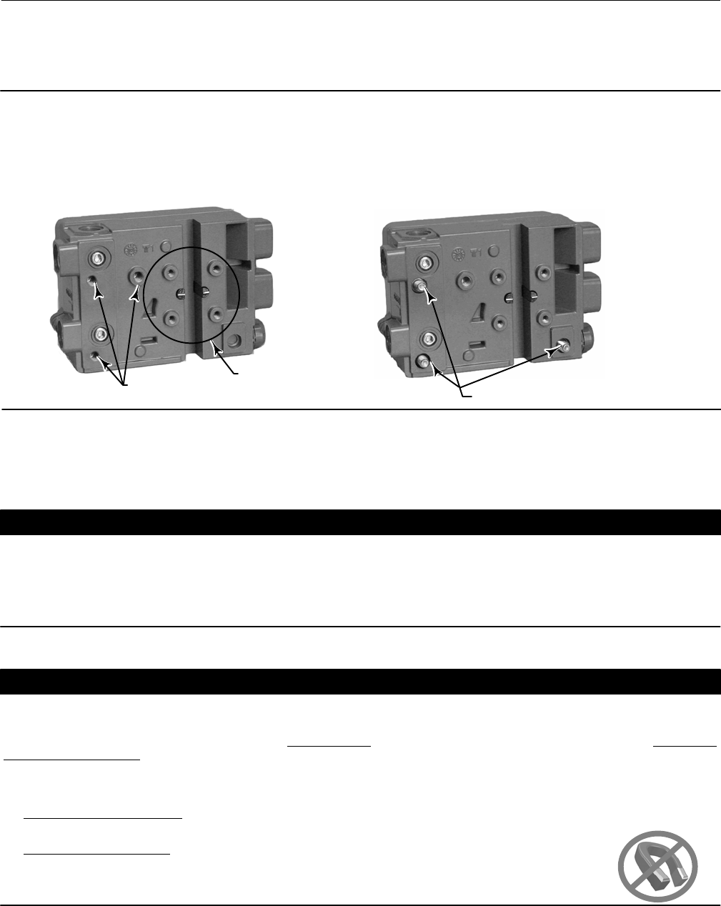
The DVC2000 housing is available in four different configurations, depending on the actuator mounting method and
threaded connection style. Figure 1 shows the available configurations.
Figure 1. Housing Variations
W9015
W9591
HOUSINGS FOR
LINEAR AND ROTARY ACTUATORS
HOUSINGS FOR
FISHER GX ACTUATORS
LINEAR, M8 ROTARY NAMUR, M6
CAPTIVE MOUNTING BOLTS, M8
CONNECTIONS AVAILABLE:
M20 CONDUIT AND G1/4 PNEUMATIC
1/2 NPT CONDUIT AND 1/4 NPT PNEUMATIC
CONNECTIONS AVAILABLE:
M20 CONDUIT AND G1/4 PNEUMATIC
1/2 NPT CONDUIT AND 1/4 NPT PNEUMATIC
PNEUMATIC CONNECTIONS
CONDUIT CONNECTIONS
The feedback system for the DVC2000 digital valve controller utilizes a magnetic field for true linkage‐less,
non‐contacting position measurement. In order to prevent inadvertent stem movement while the instrument is in
operation, magnetic tools (such as a magnetic‐tipped screwdriver) should not be used.
CAUTION
The magnet material has been specifically chosen to provide a long‐term stable magnetic field. However, as with any
magnet, care must be taken when handling the magnet assembly. Another high powered magnet placed in close proximity
(less than 25 mm) can cause permanent damage. Potential sources of damaging equipment include, but are not limited to:
transformers, DC motors, stacking magnet arrays.
CAUTION
General Guidelines for use of High Power Magnets with Positioners
Use of high power magnets in close proximity to any positioner which is operating a process should be avoided. Regardless
of the positioner model, high power magnets can affect the positioner’s ability to control the valve. Technicians should
avoid the use of high power magnets in close proximity with any positioner.
Use of Magnetic Tools with the DVC2000
D Magnetic Tip Screw Drivers – Magnetic tip screw drivers should not be brought in close proximity to the DVC2000 or the
magnetic feedback array (located at the back of the instrument) during process operations.
D Calibrator Strap Magnets – These are high power magnets used to hold 4-20 ma calibrators.
Normally, these calibrators would not be used while an instrument is controlling the process.
High power magnets should be kept at least 15 cm (6 inches) from the DVC2000.
Quick Start Guide
D103203X012
DVC2000 Digital Valve Controller
April 2014
7
Note
As a general rule, do not use less than 50% of the magnet array for full travel measurement. Performance will decrease as the array
is increasingly subranged.
The linear magnet arrays have a valid travel range indicated by arrows molded into the piece. This means that the hall sensor (on
the back of the DVC2000 housing) has to remain within this range throughout the entire valve travel. See figure 2.
The linear magnet arrays are symmetrical. Either end may be up.
There are a variety of mounting brackets and kits that are used to mount the DVC2000 to different actuators.
However, despite subtle differences in fasteners, brackets, and connecting linkages, the procedures for mounting can
be categorized as follows:
D Air‐to‐open sliding‐stem (linear) actuators
D Air‐to‐close sliding‐stem (linear) actuators
D Air‐to‐open Fisher GX actuator
D Air‐to‐close GX actuator
D Rotary actuators with travel up to 90 degrees
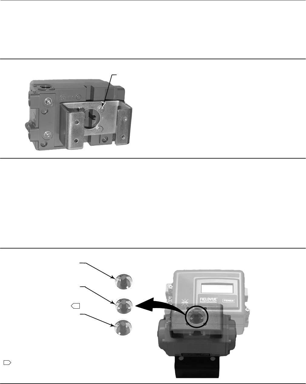
See figure 3 for the different travel feedback magnet pieces.
Figure 2. Travel Range
INDEX MARK
VALID TRAVEL RANGE
50 mm (2 INCH) SHOWN
MAGNET ASSEMBLY
(ATTACHED TO VALVE STEM)
W8830
Figure 3. Magnet Assemblies
W9014
SLIDING STEM (LINEAR)
50 mm (2‐INCH)
ROTARY
90
NOTE: VALID TRAVEL RANGE INDICATED BY WHITE ARROWS
SLIDING STEM (LINEAR)
25 mm (1‐INCH)
Quick Start Guide
D103203X012
DVC2000 Digital Valve Controller
April 2014
8
Sliding-Stem (Linear) Actuators
1. Isolate the control valve from the process line pressure and release pressure from both sides of the valve body. Shut
off all pressure lines to the actuator, releasing all pressure from the actuator. Use lock‐out procedures to be sure
that the above measures stay in effect while you work on the equipment.
2. Attach the mounting bracket to the actuator.
3. Loosely attach the feedback pieces and magnet assembly to the valve stem connector. Do not tighten the fasteners
because fine adjustment is required.
CAUTION
Do not install a magnet array that is shorter than the physical travel of the actuator. Loss of control will result from the
magnet array moving outside the range of the index mark in the feedback slot of the DVC2000 housing.
4. Using the alignment template (supplied with the mounting kit), position the feedback array inside the retaining
slot.
5. Align the magnet array as follows:
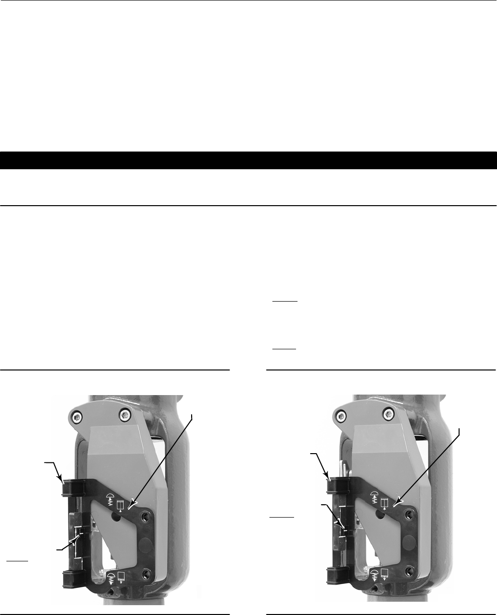
D For air‐to‐open actuators (e.g. Fisher 667) vertically align the magnet array so that the center line of the
alignment template is lined up as close as possible with the upper extreme of the valid travel range on the
feedback array. See figure 4.
D For air‐to‐close actuators (e.g. Fisher 657) vertically align the magnet array so that the center line of the
alignment template is lined up as close as possible with the lower extreme of the valid travel range on the
feedback array. See figure 5.
Figure 4. Air‐to‐Open Magnet Array Alignment
W9718
ALIGNMENT
TEMPLATE
RETAINING
SLOT
LINE UP WITH
UPPER EXTREME
OF VALID TRAVEL
RANGE
Figure 5. Air‐to‐Close Magnet Array Alignment
ALIGNMENT
TEMPLATE
W9719
RETAINING
SLOT
LINE UP WITH
LOWER EXTREME
OF VALID TRAVEL
RANGE
Quick Start Guide
D103203X012
DVC2000 Digital Valve Controller
April 2014
9
6. Tighten the fasteners and remove the alignment template.
Note
Use a flat end hex key to tighten the mounting assembly fasteners to a torque of 2.37 N•m (21 in•lbf) for 4 mm screws, and
5.08 N•m (45 in•lbf) for 5 mm screws. While tightening the fasteners using the hex key should be sufficient, blue (medium) thread
locker may be used for additional security.
7. Mount the digital valve controller to the mounting bracket, using the mounting bolts. See figure 6.
8. Check for clearance between the magnet assembly and the DVC2000 feedback slot. The magnet assembly should
be positioned so that the index mark in the feedback slot of the DVC2000 housing is within the valid range on the
magnet assembly throughout the range of travel. See figure 2.
9. Install tubing between the actuator casing and the pneumatic positioner output connection that has the arrow
pointing away from the opening. See figure 7.
Figure 6. Mounting Holes for Linear Actuators
W9015
M8 THREADED
MOUNTING
HOLES
Figure 7. Conduit and Pneumatic Thread Variations
W9016
ARROW P0INTING
AWAY FROM PORT =
OUTPUT TO ACTUATOR
ARROW P0INTING
TOWARDS THE PORT =
AIR SUPPLY IN
1/4 NPT
PNEUMATIC
CONNECTIONS
G1/4
PNEUMATIC
CONNECTIONS
Quick Start Guide
D103203X012
DVC2000 Digital Valve Controller
April 2014
10
Mounting on GX Actuators
The DVC2000 digital valve controller mounts directly on the GX actuator without the need for a mounting bracket.
However, in applications where the process temperature exceeds 80_C (176_F), it may be necessary to apply an
insulating gasket between the actuator yoke and the DVC2000, as shown in figure 8. The heat conducted from the
process line will transmit through the valve body and actuator and ultimately to the DVC2000. Temperature seen at
the DVC2000 is a function of the ambient temperature as well as the process temperature. Guidelines on when to
apply the high temperature gasket set are shown in figure 9.
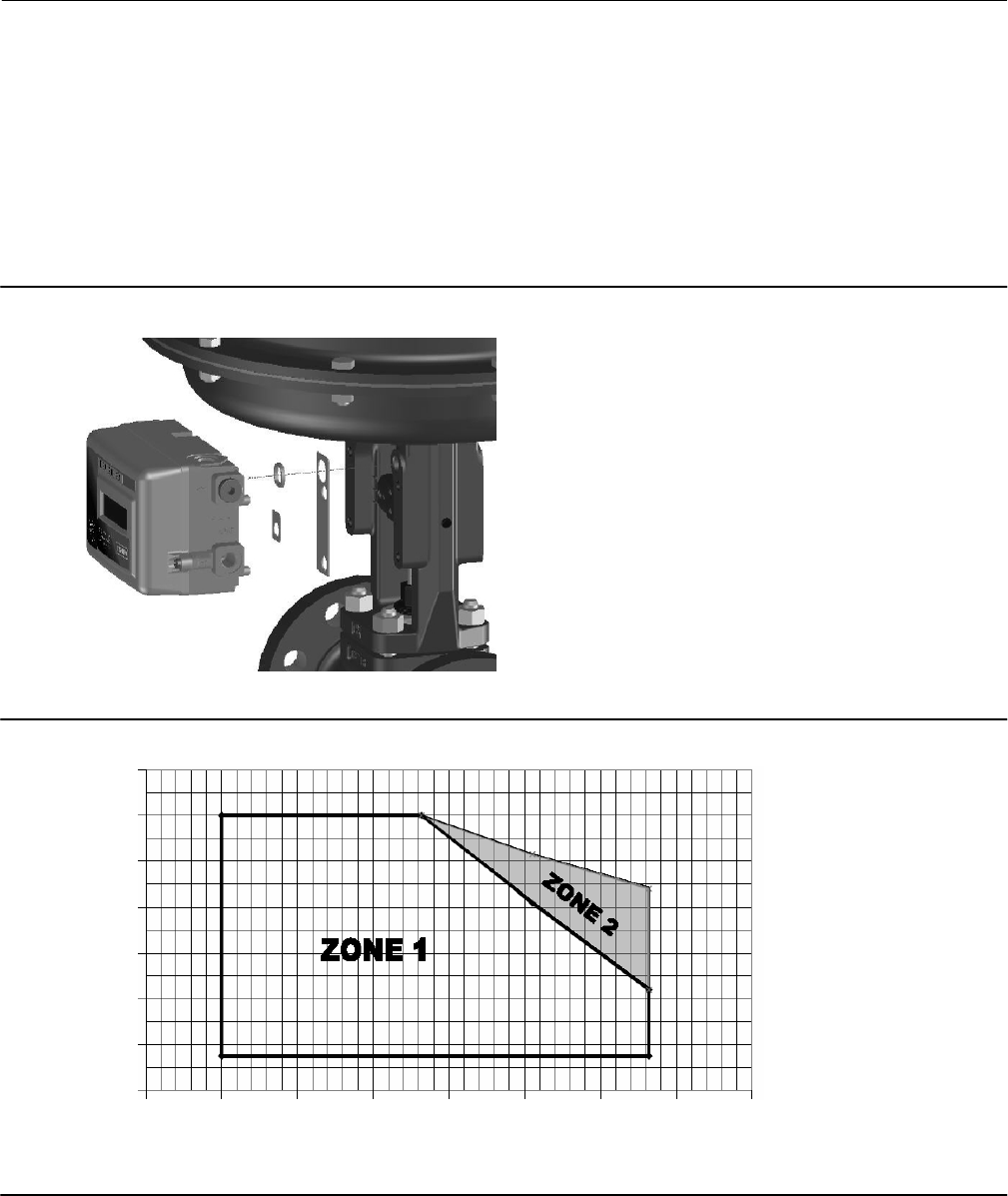
Figure 8. Mounting to Fisher GX Actuator with Insulating Gasket and O‐Ring.
Figure 9. Guidelines for Applying High Process Temperature Solutions to the Fisher GX and FIELDVUE DVC2000
100
80
60
40
20
0
-20
-40
-100 0
-50
NOTES
ZONE 1: STANDARD GX BONNET AND STANDARD DVC2000 MOUNTING APPLY.
ZONE 2: REQUIRES GX EXTENSION BONNET OR HIGH TEMPERATURE DVC2000 GASKET SET.
PROCESS TEMP (C)
AMBIENT TEMP (C)
50 100 150 200 250 300
Note
The GX extension bonnet option is an alternate way to address the high process temperature influence on the DVC2000. However,
if the extension bonnet is used, the high temperature DVC2000 mounting kit is not required.
Quick Start Guide
D103203X012
DVC2000 Digital Valve Controller
April 2014
11
If the process and ambient temperatures exceed the limits indicated by zone 2, then the DVC2000 high temperature mounting kit
can not be used. If temperatures exceed zone 2, you must use an extension bonnet or bracket mounted instrument.
Identify the yoke side to mount the DVC2000 digital valve controller based on the actuator fail mode. Refer to the GX
Control Valve and Actuator System instruction manual (D103175X012).
1. Isolate the control valve from the process line pressure and release pressure from both sides of the valve body. Shut
off all pressure lines to the actuator, releasing all pressure from the actuator. Use lock‐out procedures to be sure
that the above measures stay in effect while you work on the equipment.
2. Loosely attach the feedback pieces and magnet assembly to the valve stem connector. Do not tighten the fasteners
because fine adjustment is required.
CAUTION
Do not install a magnet array that is shorter than the physical travel of the actuator. Loss of control will result from the
magnet array moving outside the range of the index mark in the feedback slot of the DVC2000 housing.
3. Using the alignment template (supplied with the mounting kit), position the feedback array inside the retaining
slot.
4. Align the magnet array as follows:
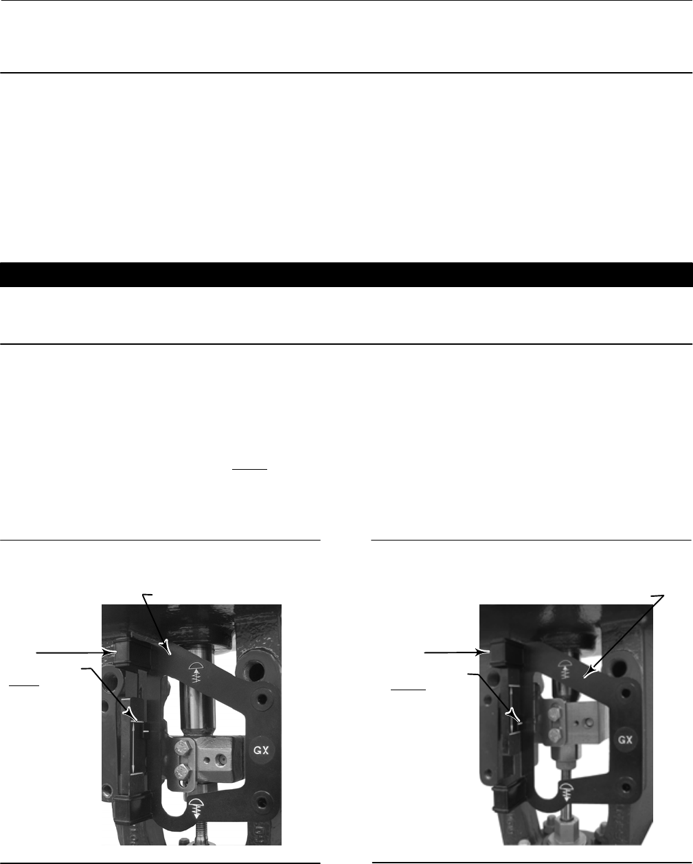
D For air‐to‐open GX actuators vertically align the magnet array so that the center line of the alignment template is
lined up as close as possible with the upper extreme of the valid travel range on the feedback array. See figure 10.
D For air‐to‐close GX actuators vertically align the magnet array so that the center line of the alignment template is
lined up as close as possible with the lower extreme of the valid travel range on the feedback array. See figure 11.
Figure 10. Air‐to‐Open Fisher GX Magnet Array
Alignment
W9218
ALIGNMENT TEMPLATE
LINE UP WITH
UPPER EXTREME
OF VALID TRAVEL
RANGE
RETAINING
SLOT
Figure 11. Air‐to‐Close Fisher GX Magnet Array
Alignment
ALIGNMENT TEMPLATE
W9219
LINE UP WITH
LOWER EXTREME
OF VALID TRAVEL
RANGE
RETAINING
SLOT
Quick Start Guide
D103203X012
DVC2000 Digital Valve Controller
April 2014
12
5. Tighten the fasteners and remove the alignment template. Continue on with the appropriate step 6 below.
Note
Use a flat end hex key to tighten the mounting assembly fasteners to a torque of 2.37 N•m (21 in•lbf) for 4 mm screws, and
5.08 N•m (45 in•lbf) for 5 mm screws. While tightening the fasteners using the hex key should be sufficient, blue (medium) thread
locker may be used for additional security.
For Air‐to‐Open GX Actuators
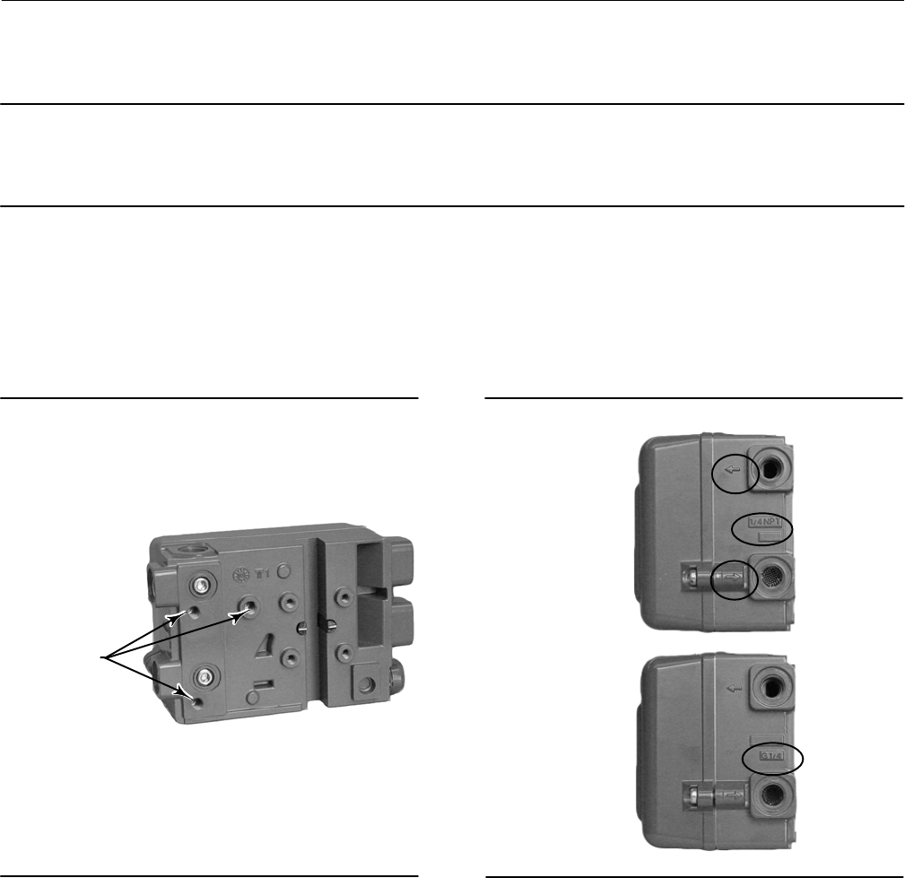
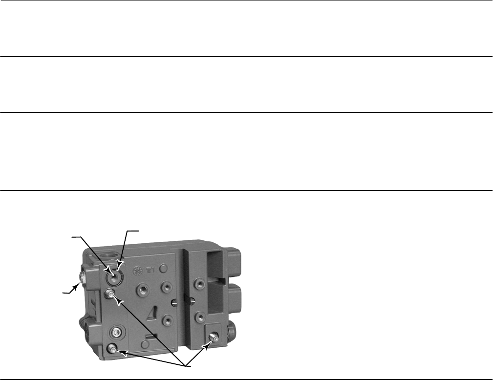
6. Remove the top plug (R1/8) from the back of the DVC2000 housing. This pneumatic output port on the DVC2000
lines up with the integral GX actuator pneumatic port. See figure 12.
Figure 12. Modifications for Fisher GX Actuator - Air‐to‐Open Construction Only
W9019
REMOVE THE
R1/8 PLUG
ADD THE 1/4 NPT
OR G1/4 PLUG
INSTALL THE O‐RING BEFORE
ASSEMBLING TO THE GX ACTUATOR
M8 MOUNTING BOLTS
7. Install the plug (either G1/4 or 1/4 NPT, included in the mounting kit) to the external output pneumatic port.
8. Remove the cover of the digital valve controller.
9. Using a 6 mm hex wrench, attach the digital valve controller to the GX actuator mounting pad on the side that has
the open pneumatic port. Be sure to place the O‐ring between the digital valve controller's pneumatic output and
the actuator mounting pad. Pneumatic tubing is not required because the air passages are internal to the actuator.
10. Check for clearance between the magnet assembly and the DVC2000 feedback slot. The magnet assembly should
be positioned so that the index mark in the feedback slot of the DVC2000 housing is within the valid range on the
magnet assembly throughout the range of travel. See figure 2.
11. Install a vent in the port on the upper diaphragm casing's air supply connection on the actuator yoke leg.

Quick Start Guide
D103203X012
DVC2000 Digital Valve Controller
April 2014
13
Air‐to‐Close GX Actuators
6. Remove the cover of the digital valve controller.
7. Using a 6 mm hex wrench, attach the digital valve controller to the GX actuator mounting pad.
Note
The O‐ring and G1/4 or 1/4 NPT plugs (supplied in the mounting kit) are not used with this actuator construction.
8. Check for clearance between the magnet assembly and the DVC2000 feedback slot. The magnet assembly should
be positioned so that the index mark on the pole pieces (back of the positioner housing) is within the valid range on
the magnet assembly throughout the range of travel. See figure 2.
9. Install tubing between the actuator casing and the pneumatic positioner output connection that has the arrow
pointing away from the opening. See figure 7.
10. Install a vent in the port on the lower diaphragm casing.
Note
When field converting a GX actuator from fail‐open to fail‐closed (or vice‐versa), you will need to change the plugs for the
pneumatic passages in the DVC2000 housing.
D To convert to fail‐closed, remove the R1/8 pneumatic plug on the back of the DVC2000 housing and install an O‐ring. Plug
the external pneumatic output with a 1/4 NPT or G1/4 plug (depending on the housing version). Refer to figure 12.
D To convert to fail‐open, remove the external pneumatic plug (1/4 NPT or G1/4 plug depending on the housing version).
Install an R1/8 plug on the back of the DVC2000 housing. Install tubing between the pneumatic output connection of the
DVC2000 to the pneumatic port on top of the actuator casing.
Quick Start Guide
D103203X012
DVC2000 Digital Valve Controller
April 2014
14
Guidelines for Mounting on Quarter‐Turn (Rotary) Actuators
The DVC2000 digital valve controller can be mounted to any quarter‐turn (rotary) actuator, as well as those that
comply with the NAMUR guidelines. A mounting bracket and associated hardware are required. Refer to figure 13.
Figure 13. For Rotary Actuators (with Typical Mounting Bracket Shown)
W8835
M6 MOUNTING
BOLTS (4)
1. Isolate the control valve from the process line pressure and release pressure from both sides of the valve body. Shut
off all pressure lines to the actuator, releasing all pressure from the actuator. Use lock‐out procedures to be sure
that the above measures stay in effect while you work on the equipment.
2. Attach the magnet assembly to the actuator shaft. At mid‐travel, the flats on the magnet assembly should be
approximately parallel to the channel on the back of the DVC2000 housing, as shown in figure 14.
3. Install the mounting bracket on the actuator.
4. Attach the digital valve controller to the mounting bracket using the 4 mounting bolts, as shown in figure 13.
5. Check for clearance between the magnet assembly and the positioner feedback slot.
6. Install tubing between the actuator casing and the pneumatic positioner output connection that has the arrow
pointing away from the opening. See figure 7.
ORIENTATION
AT ONE TRAVEL
EXTREME
ORIENTATION
AT MID‐TRAVEL
(FLATS PARALLEL
TO DVC2000
CHANNEL)
ORIENTATION
AT THE OTHER
TRAVEL EXTREME
W8836
Figure 14. Magnetic Assembly Orientation on Quarter‐Turn Actuators
1 THIS EXAMPLE SHOWS AN ACTUATOR WITH 90 TRAVEL. ON AN ACTUATOR THAT
HAS LESS THAN 90 TRAVEL THE MAGNET ASSEMBLY MAY NOT BE PARALLEL AT THE
MID-TRAVEL POINT. TO VERIFY THE MAGNET ASSEMBLY POSITION IS IN WORKING RANGE,
CONFIRM TRAVEL COUNTS ARE WITHIN THE EXPECTED RANGE OF 175-3800 USING
VALVELINK SOFTWARE OR A FIELD COMMUNICATOR.
1
Quick Start Guide
D103203X012
DVC2000 Digital Valve Controller
April 2014
15
Electrical and Pneumatic Connections
The electrical and pneumatic connections on the digital valve controller are available with the following combinations:
D 1/4 NPT supply and output with 1/2 NPT conduit connections
D G1/4 supply and output with M20 conduit connections
Supply Connections
WARNING
Severe personal injury or property damage may occur from process instability if the instrument air supply is not clean, dry
and oil‐free. While use and regular maintenance of a filter that removes particles larger that 40 micrometers in diameter
will suffice in most applications, check with an Emerson Process Management field office and industry instrument air
quality standards for use with corrosive air or if you are unsure about the proper amount or method of air filtration or filter
maintenance.
Supply pressure must be clean, dry air or noncorrosive gas that meets the requirements of ISA Standard 7.0.01. A
maximum 40 micrometer particle size in the air system is acceptable. Further filtration down to 5 micrometer particle
size is recommended. Lubricant content is not to exceed 1 ppm weight (w/w) or volume (v/v) basis. Condensation in
the air supply should be minimized.
A Fisher 67CFR filter regulator with standard 5 micrometer filter, or equivalent, may be used to filter and regulate
supply air. If pressure regulation is not required, a 10 micron in‐line filter may be used.
Connect the nearest suitable supply source to the connection with the arrow pointing towards the opening (see
figure 7).
Electrical Connections
WARNING
Select wiring and/or cable glands that are rated for the environment of use (such as hazardous area, ingress protection and
temperature). Failure to use properly rated wiring and/or cable glands can result in personal injury or property damage
from fire or explosion.
Wiring connections must be in accordance with local, regional, and national codes for any given hazardous area approval.
Failure to follow the local, regional, and national codes could result in personal injury or property damage from fire or
explosion.
The valve may move in an unexpected direction when power is applied to the digital valve controller. To avoid personal
injury and property damage caused by moving parts, keep hands, tools, and other objects away from the valve/actuator
assembly when applying power to the instrument.
The digital valve controller is normally powered by a control system output card. The use of shielded cable will ensure
proper operation in electrically noisy environments. Wire size requirements are 14 AWG maximum, 26 AWG
minimum.
Be sure to follow the appropriate I.S. circuit guidelines when installing field wiring to the loop terminals as well as the
limit switch and transmitter terminals.
Quick Start Guide
D103203X012
DVC2000 Digital Valve Controller
April 2014
16
Wire the digital valve controller as follows:
1. Remove the main instrument cover.
2. Route the field wiring into the terminal box through the conduit connection. When applicable, install conduit using
local and national electrical codes that apply to the application.
3. Connect the control system output card positive wire “current output” to the +11 terminal. Connect the control
system output card negative (or return) wire “current output” to the -12 terminal.
4. Two ground terminals are available for connecting a safety ground, earth ground, or drain wire. These ground
terminals are electrically identical. Make connections to these terminals following national and local codes and
plant standards.
5. Replace the cover if the local interface is not being used for configuration or calibration.
Options Boards
All three options circuits (transmitter, switch 1 and switch 2) control current from an external power source similar to
the operation of a 2‐wire transmitter.
Limit Switches
On units that are supplied with integral limit switches, additional terminals provide the field wiring connection point.
The limit switches are isolated from each other and from the digital valve controller's primary feedback. If only one
switch is to be used, you must use channel 1. Although electrically isolated per Intrinsic Safety requirements, channel 2
derives its power from channel 1. Therefore channel 2 cannot be used alone.
Wire the limit switches as follows:
1. Remove the main instrument cover.
2. Route the field wiring into the terminal box through the conduit connection. When applicable, install conduit using
local and national electrical codes that apply to the application.
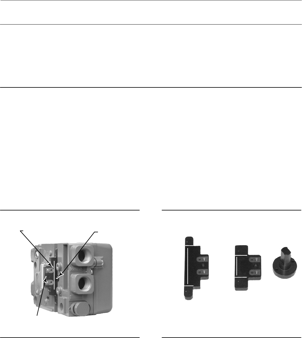
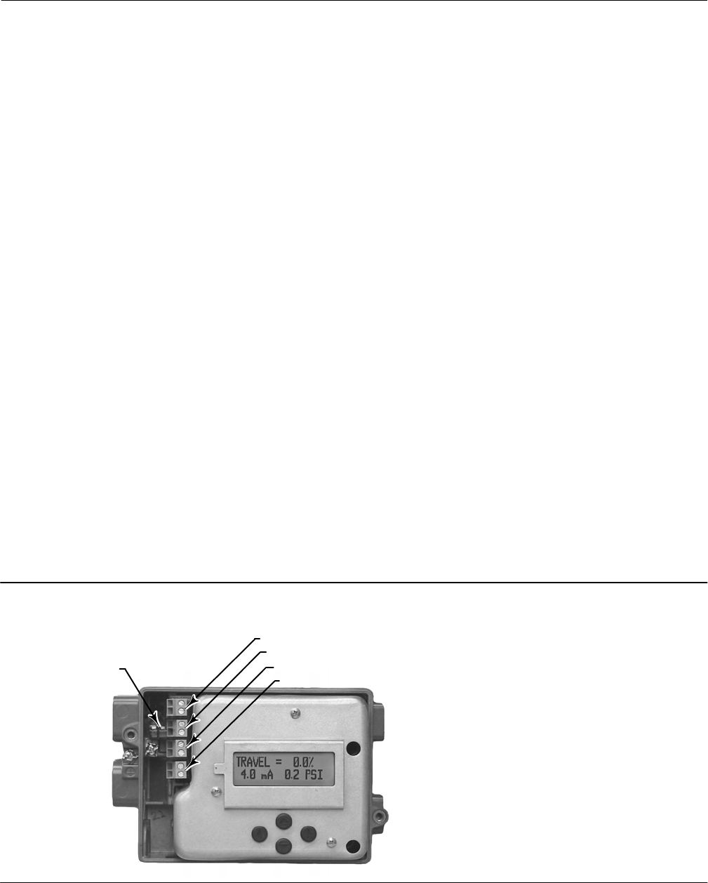
3. Connect the control system input card positive wire “switch input” to the +41 terminal. Connect the control system
input card negative wire “switch input” to the -42 terminal. Refer to figure 15.
Figure 15. Loop, Transmitter, and Limit Switch Terminals
HART
COMMUNICATION
TERMINATION
POINTS
+31/ -32 (TRANSMITTER)
+11/ -12 (LOOP)
+41/ -42 (SWITCH 1)
+51/ -52 (SWITCH 2)
W8838

Quick Start Guide
D103203X012
DVC2000 Digital Valve Controller
April 2014
17
4. If a second switch is to be used, connect the control system input card positive wire “switch input” to the +51
terminal. Connect the control system input card negative wire “switch input” to the -52 terminal.
5. Proceed to the Basic Setup section to configure the switch action.
6. Replace the cover if the local interface is not being used for configuration or calibration.
Position Transmitter
On units that are supplied with an integral valve position transmitter, additional terminals provide the field wiring
connection point. The position transmitter circuit in the DVC2000 derives its operating power from the 4‐20 mA
control system input in the same manner as a 2‐wire transmitter. In addition, the transmitter function gets position
information (through an opto‐isolator) from the digital valve controller so the 4‐20 mA position control loop must also
be powered in order for the position transmitter to provide an output representing the valve position.
Note
In an Intrinsically Safe installation with the options in use, the wire pairs must be shielded. Additionally, to prevent cross‐wiring, the
individual wires must not be exposed beyond the terminal barrier walls.
Wire the position transmitter as follows:
1. Remove the main instrument cover.
2. Route the field wiring into the terminal box through the conduit connection. When applicable, install conduit using
local and national electrical codes that apply to the application.
3. Connect the control system input card positive wire “current input” to the +31 terminal. Connect the control
system input card negative wire “current input” to the -32 terminal. Refer to figure 15.
4. Replace the cover if the local interface is not being used for configuration or calibration.
Vent
By design, the instrument exhausts supply air into the area under the cover. The vent should be left open to prevent
pressure buildup under the cover and to drain any moisture that may accumulate in the housing. The control valve
assembly should be installed so that the primary vent provides gravitational draining.
If a remote vent is required, the vent line must be as short as possible with a minimum number of bends and elbows.
Communications Connections
A HART communicating device, such as a Field Communicator or a personal computer running ValveLink software
communicating through a HART modem, interfaces with the DVC2000 digital valve controller. You can connect at any
point on the 4‐20 mA loop. Alternatively, convenient termination points are located on the termination board (figure
15). The instrument must be powered before digital communication will commence.
Quick Start Guide
D103203X012
DVC2000 Digital Valve Controller
April 2014
18
Basic Setup and Calibration
The local operator interface is available on all DVC2000 digital valve controllers. The interface consists of a liquid
crystal display, four pushbuttons, and a switch for position transmitter configuration. The DVC2000 is supplied with
one of three different language packs preinstalled, depending on the firmware revision and ordering option. Language
pack options are shown in table 1. To configure the language, follow the procedure outlined in the Basic Setup section.
The instrument must be powered with at least 8.5 volts and 3.5 mA to operate the local interface. Certain procedures
require up to 20 mA of current.
CAUTION
When accessing the terminals or pushbuttons, proper means of electrostatic discharge protection is required. Failure to
provide appropriate protection can cause the valve to move, resulting in valve/actuator instability.
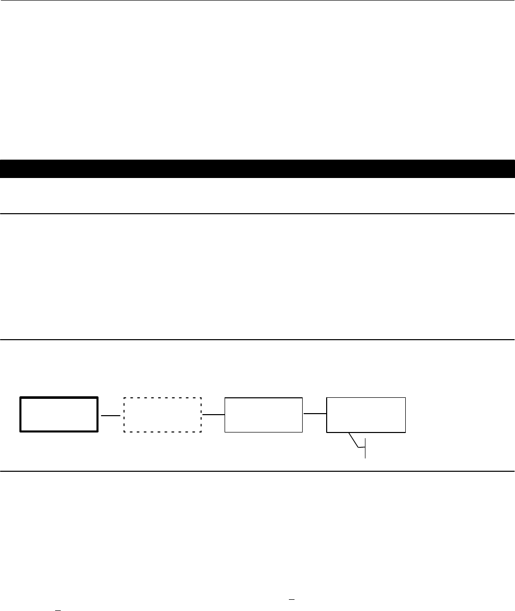
Status Information
The first (home) screen on the LCD that is displayed after applying power to the instrument contains basic status
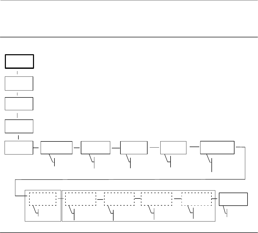
information. On an instrument that is calibrated and operating properly, the flow chart in figure 16 shows the available
information by pressing the right (") arrow key.
Figure 16. Home Screen on the LCD
Only with Optional
Transmitter / Limit Switches
TRAVEL = 66.8%
14.6 MA 0.92 BAR SWITCH 1 = OPEN
SWITCH 2 = CLOSED
OFF
ON
PROTECTION
OFF
FW3:1, HW1:2
TUNING = C
"
A"
A
"
A
TRAVEL=##.#%—Current valve travel in percent of calibrated travel.
##.# MA—Current input signal applied to the instrument in mA.
##.## BAR—Current pressure output to the actuator in the configured units (BAR, PSI or MPA).
SWITCH1—Current status of the optional limit switch wired to terminals +41 and -42.
SWITCH2—Current status of the optional limit switch wired to terminals +51 and -52.
FW#—Version of firmware running in the device.
HW#—Version of electronics hardware installed. The first number (# : #) represents the main board, the second
number (# : #) represents the secondary electronics.
TUNING = X—Current tuning set parameters configured in the device.
PROTECTION—Indicates whether the local interface is protected or not. With protection ON, the instrument cannot be
configured or calibrated with the local pushbuttons.
Quick Start Guide
D103203X012
DVC2000 Digital Valve Controller
April 2014
19
Basic Setup
WARNING
Changes to the instrument setup may cause changes in the output pressure or valve travel. Depending on the application,
these changes may upset process control which may result in personal injury or property damage.
When the DVC2000 digital valve controller is ordered as part of a control valve assembly, the factory mounts the
digital valve controller and sets up the instrument as specified on the order. When mounting to a valve in the field, the
instrument needs to be setup to match the instrument to the valve and actuator.
Before beginning basic setup, be sure the instrument is correctly mounted and powered electrically and
pneumatically.
Selecting the Language
The DVC2000 is supplied with one of three different language packs preinstalled, depending on the firmware revision
and the ordering option. See table 1 for language pack options.
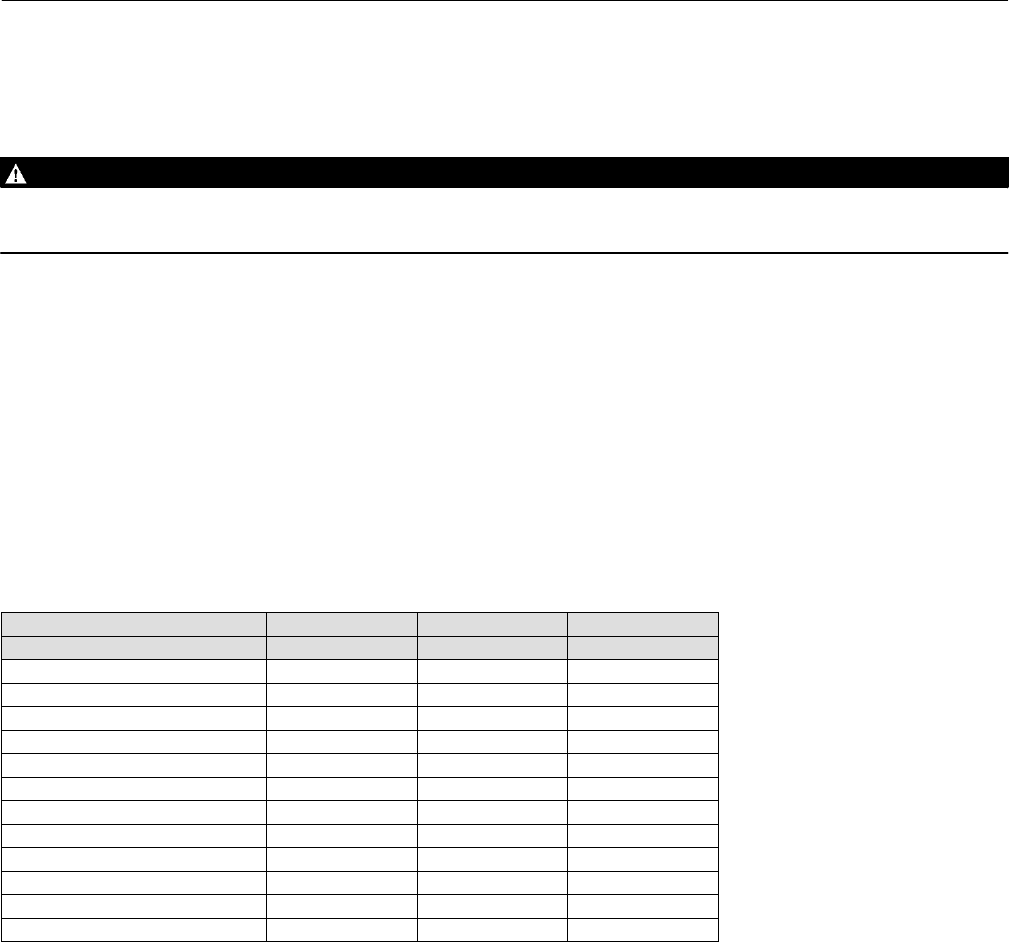
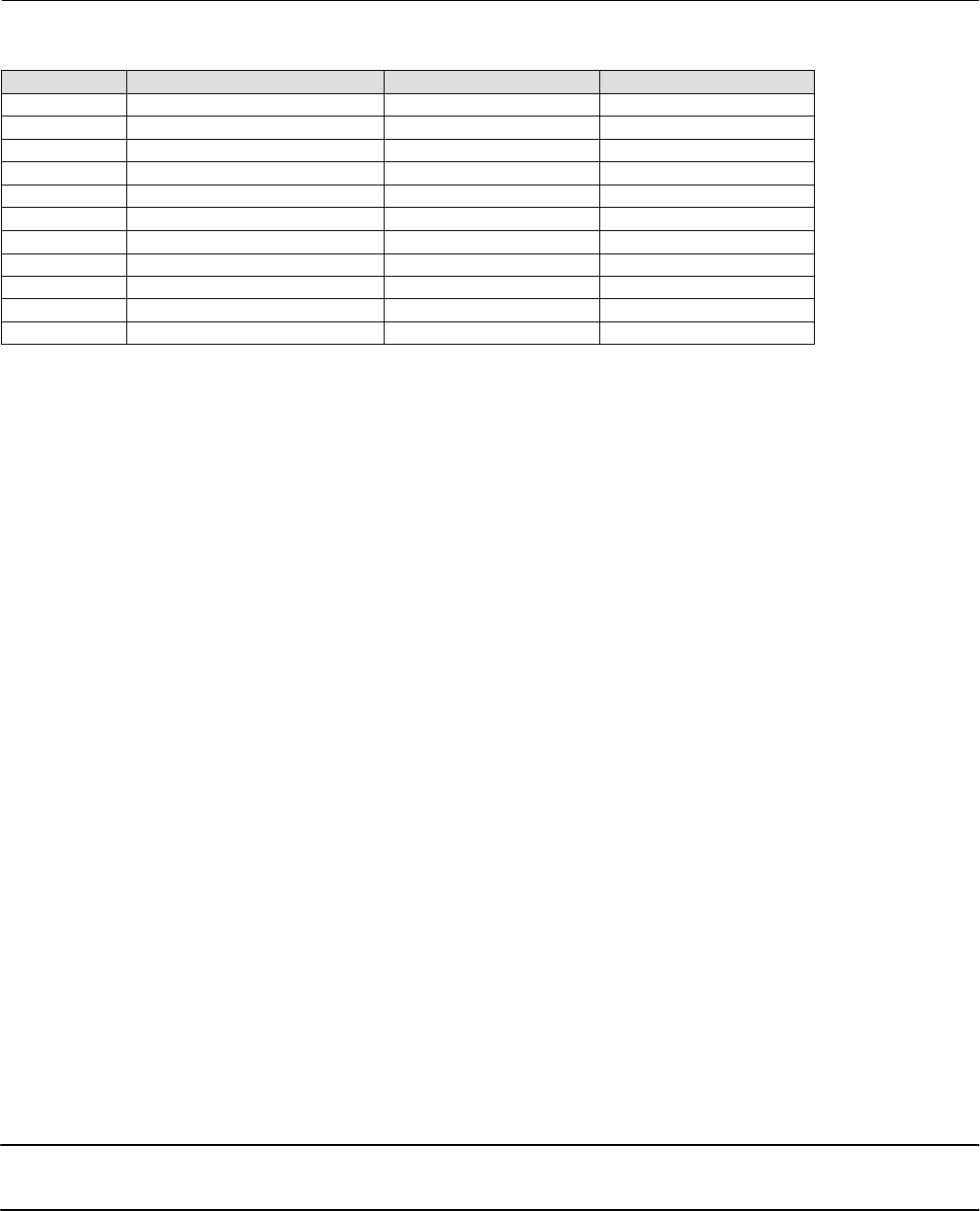
Table 1. Language Pack Options
Firmware Revision 1 or 2 3 3
Language Pack Standard Standard Optional
English X X X
Japanese X X X
Chinese X X X
French X X X
German X X X
Italian X X X
Spanish X X X
Portuguese X
Russian X
Polish X
Czech X
Arabic X
Only firmware revision 3 or later will allow you to download different language packs to the DVC2000 using ValveLink
software.
To access the language selection screen on the DVC2000 local interface press the four arrow keys simultaneously for
three (3) seconds.
Use the UP or DOWN (Y or B) arrow keys to select the appropriate language. Press the RIGHT (") arrow key to
confirm your selection.
Quick Start Guide
D103203X012
DVC2000 Digital Valve Controller
April 2014
20
Quick Setup
When installing the DVC2000 digital valve controller on an actuator for the first time, the quick setup procedure will
calibrate and tune the instrument automatically. Table 2 lists the values that are preconfigured at the factory.
Table 2. Factory Default Settings Accessible from the Local Interface
Setup Parameter Default Setting
Zero Control Signal Open(1)
Pressure Units BAR or PSIG
Input Range Low 4 mA
Input Range High 20 mA
Characteristic Linear
Transmitter (optional feature) 4 mA = Valve Closed
Switch 1 Trip Point (optional feature) 90%
Switch 1 Closed (optional feature) Above 90%
Switch 2 Trip Point (optional feature) 10%
Switch 2 Closed (optional feature) Below 10%
1. If the instrument is shipped mounted on an actuator, this value depends upon the actuator on which the instrument is mounted.
WARNING
During calibration the valve will move full stroke. Changes to the tuning set may also cause the valve / actuator assembly to
stroke. To avoid personal injury and property damage caused by moving parts, keep hands, tools, and other objects away
from the valve/actuator assembly.
Note
If optional limits switches are being used, power must be applied to the switch circuits throughout the quick setup routine. Failure
to power the switches may result in incorrect switch orientation.
Refer to the DETAILED SETUP procedure for further explanation of the parameters.
To access the QUICK SETUP routine from the home screen, press the DOWN (B) arrow key and then the RIGHT (")
arrow key. A warning will advise you that this procedure will cause the valve to move. Another RIGHT (") button press
will begin the calibration process. Pressing the LEFT (A) arrow key will bring you back to the main menu.
This procedure will automatically calibrate the instrument and apply tuning parameters specifically fit for the size of
the actuator.
To abort the procedure at any time, press the RIGHT (") and LEFT (A) arrow keys together for 3 seconds.
When the procedure is complete, press the RIGHT (") arrow key to return to the status screen. If the RIGHT (")
button is not pressed within 30 seconds, the device will automatically revert back to the status screen.
Figure 17. Quick Setup
TRAVEL = 66.8%
14.6 MA 0.92 BAR
VALVE WILL MOVE
PRESS FOR 3 SEC
QUICK SETUP FINDING 0%... QUICK SETUP
COMPLETE
""
"
A
Y
B
Quick Start Guide
D103203X012
DVC2000 Digital Valve Controller
April 2014
21
Travel Calibration
WARNING
During calibration the valve will move full stroke. To avoid personal injury and property damage caused by the release of
pressure or process fluid, isolate the valve from the process and equalize pressure on both sides of the valve or bleed off the
process fluid.
Note
If optional limits switches are being used, power must be applied to the switch circuits throughout the automatic or manual
calibration routine. Failure to power the switches may result in incorrect switch orientation.
To manually calibrate the instrument or automatically calibrate the instrument without changing the tuning values,
the TRAVEL CALIBRATION routine is available. To access this procedure from the home screen, press the DOWN (B)
arrow key two times and then the RIGHT (") arrow key once. From there follow the prompts as illustrated in figure 18.
Figure 18. Travel Calibration
TRAVEL
CALIBRATION "
"
"
A"
A
FINDING
100%...
FINDING 0%... FINDING 50%...
MOVE VALVE TO
100% TRAVEL
FINDING 50%...
CALIBRATION
AUTOMATIC VALVE WILL MOVE
PRESS FOR 3 SEC
CALIBRATION
COMPLETE
CALIBRATION
FAILED
SAVE & EXIT?
PRESS
"
MOVE VALVE TO
0% TRAVEL
AUTOMATIC
MANUAL
"
""
"
"
"
SAVE & EXIT?
EXIT W/O SAVING?
TRAVEL = 66.8%
14.6 MA 0.92 BAR
QUICK SETUP
Y
B
Y
B
AUTO
MANUAL
Note
If the valve is manually calibrated to travel less than the physical travel stops allow, manual tuning (page 22) may be required to
optimize the valve response.
Automatic calibration will provide status information as the procedure is running. Manual calibration will require you
to first adjust the input current to move the valve and then to press the RIGHT (") arrow key. After manual calibration
is complete, you will have the choice to save the calibration or exit the procedure without saving. If you exit without
saving, the last saved calibration data will be restored.
Quick Start Guide
D103203X012
DVC2000 Digital Valve Controller
April 2014
22
Tuning
WARNING
Changes to the tuning set may cause the valve/actuator assembly to stroke. To avoid personal injury and property damage
caused by moving parts, keep hands, tools, and other objects away from the valve/actuator assembly.
To manually tune the instrument or automatically tune the instrument without changing the calibration values, the
TUNING routine is available. To access this procedure from the home screen, press the DOWN (B) arrow key three
times and then the RIGHT (") arrow key once. From there follow the prompts as illustrated in figure 19 below.
Figure 19. Tuning
TUNING "
"
AA
AUTOTUNING
IN PROCESS...
TUNING
C
TUNING
AUTOMATIC
VALVE WILL MOVE
PRESS FOR 3 SEC
AUTOTUNING
COMPLETE
AUTOTUNE FAILED
USE MANUAL TUNING
SAVE & EXIT?
PRESS
AUTOMATIC
MANUAL
""
"
SAVE & EXIT?
EXIT W/O SAVING?
ADAMPING
NEUTRAL
+5, +4, +3, +2, +1
NEUTRAL
-5, -4, -3, -2, -1
EXPERT,
C,D,E,F,G,
H,I,J,K,L,M
"
A
TRAVEL = 66.8%
14.6 MA 0.92 BAR
QUICK SETUP
Y
B
Y
B
Y
B
TRAVEL
CALIBRATION
"
"
VALVE MAY MOVE
PRESS FOR 3 SEC
"
AUTO
MANUAL
Automatic tuning will provide status information as the procedure is running. Manual tuning will require you to choose
from one of eleven tuning sets. Each tuning set provides a preselected value for the digital valve controller gain
settings. Tuning set C provides the slowest response and M provides the fastest response. Table 3 lists the proportional
gain, velocity gain, and minor loop feedback gain values for preselected tuning sets. Manual tuning is only
recommended when the automatic tuning procedure results in failure.
Quick Start Guide
D103203X012
DVC2000 Digital Valve Controller
April 2014
23
Table 3. Gain Values for Preselected Turning Sets
Tuning Set Proportional Gain Velocity Gain Minor Loop Feedback Gain
C 5 2 55
D 6 2 55
E 7 2 55
F 8 2 52
G 9 2 49
H 10 2 46
I 11 2 44
J 12 1 41
K 14 1 38
L 16 1 35
M 18 1 35
A typical starting point for most small actuators is “C”. Using the UP (Y) and DOWN (B) arrow keys will apply the
values immediately. You can then change the input current to observe the response. When you are satisfied with the
response, press the RIGHT (") arrow key to fine tune the instrument. The UP (Y) and DOWN (B) arrow keys will apply
more or less damping to fine tune the overshoot after a step input change.
After manual tuning is complete, you will have the choice to save the tuning data or exit the procedure without saving.
If you exit without saving, the last saved tuning data will be restored.
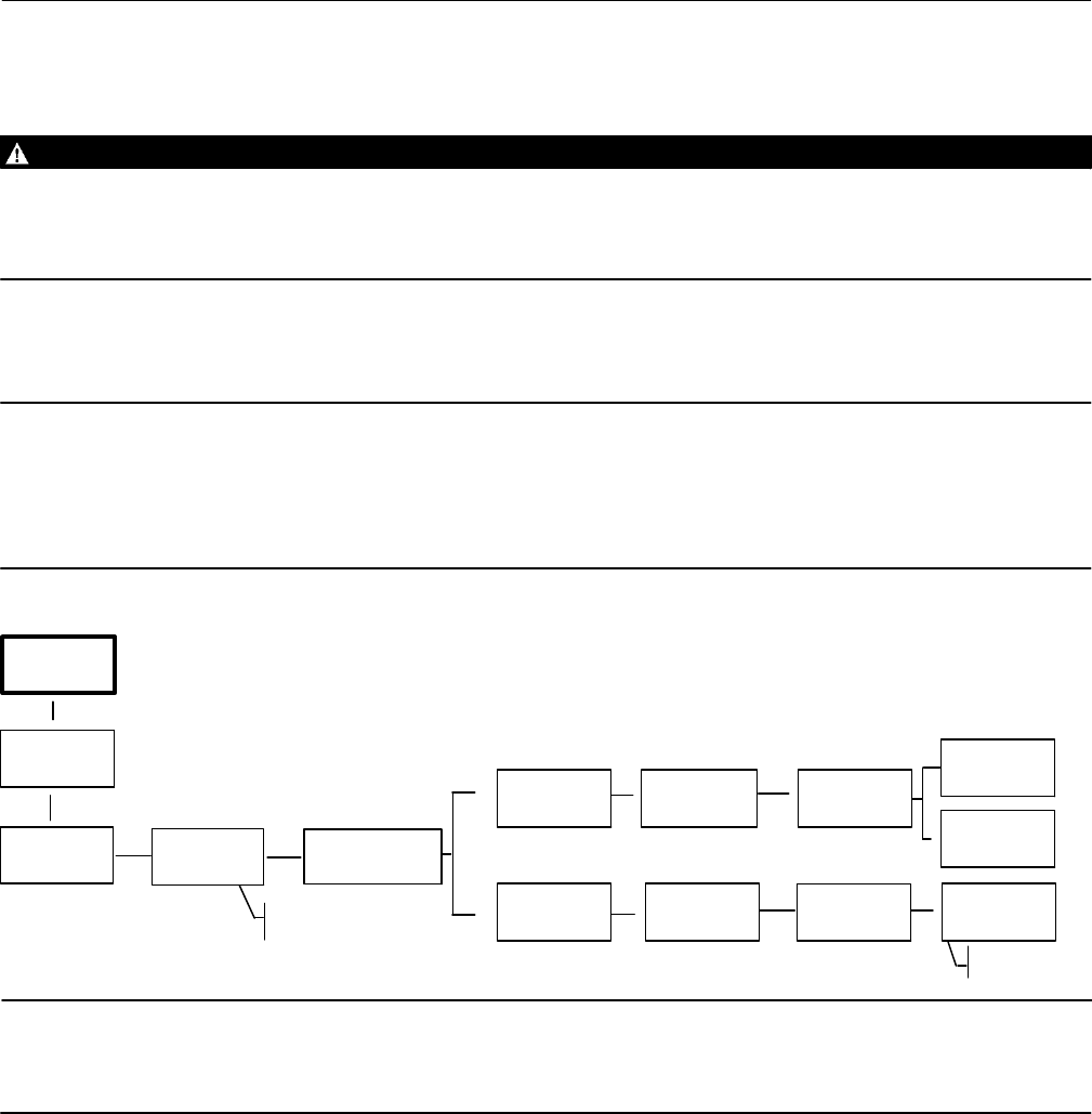
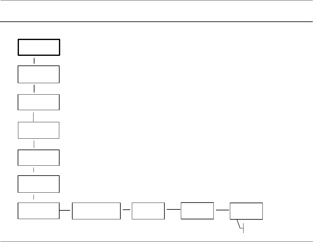
Detailed Setup
If the factory default configuration values need to be changed, the DETAILED SETUP procedure provides access. See
figure 20 for the flowchart showing the sequence of screens. To access this procedure from the home screen, press the
DOWN (B) arrow key four times. The RIGHT (") arrow key brings you into the configuration items. Once you are in a
particular configuration item, use the UP (Y) and DOWN (B) arrow keys to select the appropriate choice.
To exit this procedure, press the RIGHT (") arrow key and view the remaining configuration items until you reach the
exit screen. If you exit without saving, the last saved configuration data will be restored.
Below is an explanation of the configuration items.
Zero Control Signal—Identifies whether the valve is fully OPEN or fully CLOSED when the input is 0%. If you are unsure
how to set this parameter, disconnect the current source to the instrument. The resulting valve travel is the Zero
Control Signal. This corresponds to setting the output pressure to zero.
Pressure Units—Defines the pressure units in either PSI, BAR, or KPA.
Input Range Low—This will correspond to 0% travel if the Zero Control Signal is configured as closed. If the Zero Control
Signal is configured as open, this will correspond to 100% travel.
Input Range High—This will correspond to 100% travel if the Zero Control Signal is configured as closed. If the Zero
Control Signal is configured as open, this will correspond to 0% travel.
Characteristic—Defines the relationship between the travel target and the ranged set point. Ranged set point is the
input to the characterization function. If the Zero Control Signal is closed, then a set point of 0% corresponds to a
ranged input of 0%. If the Zero Control Signal is open, a set point of 0% corresponds to a ranged input of 100%. Travel
target is the output from the characterization function.
Note
Travel cutoffs are enabled by default on all units.
Quick Start Guide
D103203X012
DVC2000 Digital Valve Controller
April 2014
24
The factory default characteristic is LINEAR. You can also use a QUICK OPEN, EQUAL %, or CUSTOM function. However,
the custom function is initially configured linear, unless you use a HART based host to reconfigure the custom points.
Custom configuration can be selected, but the curve cannot be modified with the local interface.
Figure 20. Detailed Setup Flow Chart
TUNING
""
AINPUT RANGE
LOW 4 MA
SWITCH1 CLOSED
ABOVE 90%
ZERO CTL SIGNAL
VALVE CLOSED PRESSURE UNITS
BAR
CHARACTERISTIC
LINEAR
INPUT RANGE
HIGH 20 MA
CLOSED
OPEN
"
"
ABOVE
BELOW
DISABLED
A
TRANSMITTER
4MA CLOSED
125%
...
-25%
TRAVEL = 66.8%
14.6 MA 0.92 BAR
QUICK SETUP
Y
B
Y
B
Y
B
TRAVEL
CALIBRATION
Y
B
DETAILED SETUP "
A"
A"
A
BAR
PSI
KPA
4MA
...
19MA
20MA
...
5MA
QUICK OPEN
LINEAR
EQUAL %
CUSTOM
CLOSED
OPEN
A
SAVE & EXIT?
EXIT W/O SAVIN
G
SAVE & EXIT?
PRESS
125%
...
-25%
BELOW
ABOVE
DISABLED
SWITCH1
TRIP POINT 90%
SWITCH2
TRIP POINT 10%
SWITCH2 CLOSED
BELOW 10%
Only with Optional Position Transmitter / Limit Switches
Only with Optional Position
Transmitter / Limit Switches
"A "
A"
A"
A
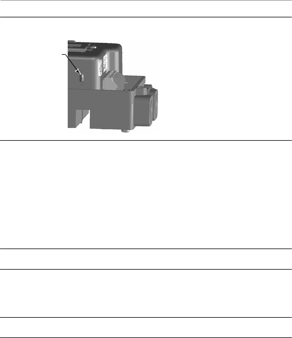
Transmitter—This configures the relationship between the valve travel and the position transmitter output signal. If
you select CLOSED, the transmitter will send 4 mA when the valve is closed. If you select OPEN, the transmitter will
send 4 mA when the valve is open.
A switch is located on the options board to select the transmitter fail signal (high+ or low-). High+ will result in a
current output of > 22.5 mA upon transmitter failure. Low- will result in a current output of < 3.6 mA. Refer to figure
21 for location and switch selection.
Quick Start Guide
D103203X012
DVC2000 Digital Valve Controller
April 2014
25
Figure 21. XMTR Switch
TRANSMITTER SWITCH
FOR FAIL SIGNAL
+ HIGH (SHOWN) OR
-LOW
W8839
Switch #1 Trip Point—Defines the threshold for the limit switch wired to terminals +41 and -42 in percent of calibrated
travel.
Switch #1 Closed—Configures the action of the limit switch wired to terminals +41 and -42. Selecting ABOVE
configures the switch to be closed when the travel is above the trip point. Selecting BELOW configures the switch to be
closed when the travel is below the trip point. Selecting DISABLED removes the icons and status from the display.
Switch #2 Trip Point—Defines the threshold for the limit switch wired to terminals +51 and -52 in percent of calibrated
travel.
Switch #2 Closed—Configures the action of the limit switch wired to terminals +51 and -52. Selecting ABOVE
configures the switch to be closed when the travel is above the trip point. Selecting BELOW configures the switch to be
closed when the travel is below the trip point. Selecting DISABLED removes the icons and status from the display.
Note
Switch #2 is only operational if power is applied to switch #1 also. Switch #2 cannot be used alone.
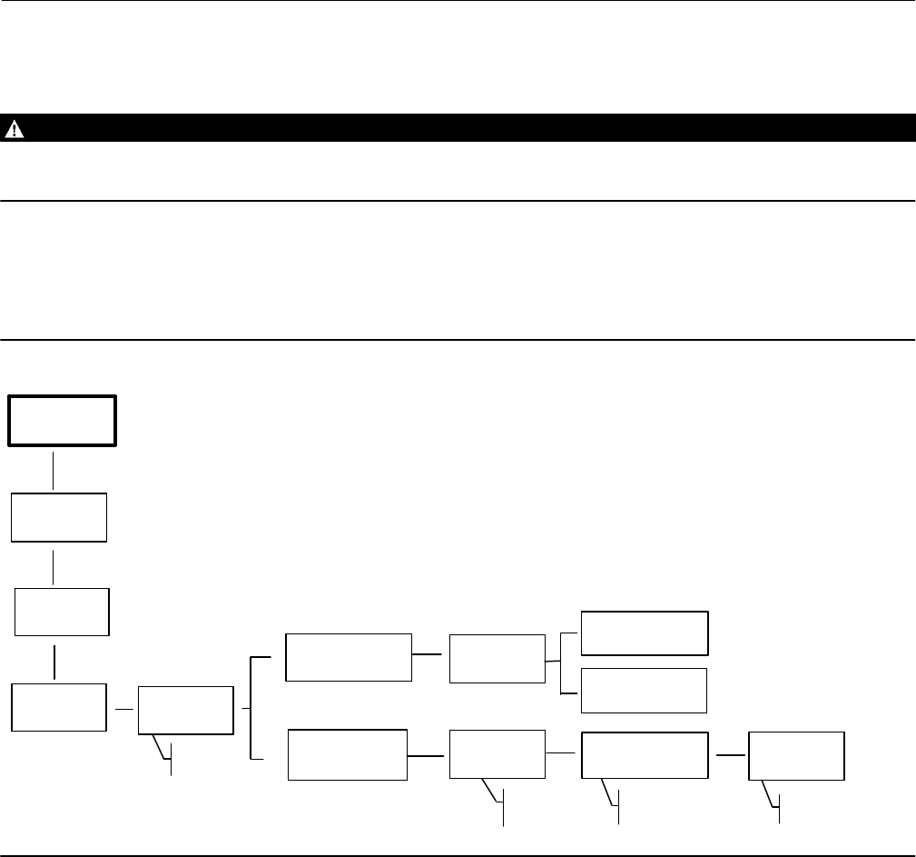
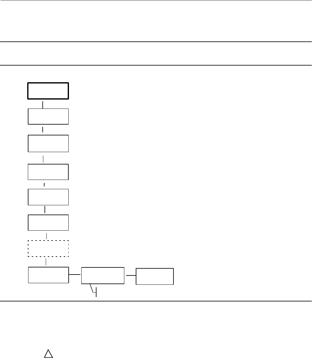
Position Transmitter Calibration
Note
This procedure will not move the control valve. The instrument will simulate an output for calibration purposes only.
This procedure is only available on units that have the optional position transmitter hardware installed. The DVC2000
digital valve controller is shipped from the factory with the position transmitter already calibrated. You do not
normally need to perform this procedure. However, if you suspect that this needs adjustment, follow the procedure
below and refer to figure 22.
Quick Start Guide
D103203X012
DVC2000 Digital Valve Controller
April 2014
26
Figure 22. Position Transmitter Calibration
SAVE & EXIT?
EXIT W/O SAVING?
SAVE & EXIT?
PRESS
""
AUSE OR
TO SEND 20MA
POSITION
TRANSMIITTER CAL "
A
USE OR
TO SEND 4MA
TUNING
TRAVEL = 66.8%
14.6 MA 0.92 BAR
QUICK SETUP
Y
B
Y
B
Y
B
TRAVEL
CALIBRATION
Y
B
DETAILED SETUP
Y
B
Y
B
ANALOG INPUT
CALIBRATION
mA OUT WILL CHANGE
PRESS FOR 3 SEC
"
A
Connect a current meter in series with the transmitter output terminals (+31 & -32) and a voltage source (such as the
DCS analog input channel). From the home screen, press the DOWN (B) arrow key six times and then press the RIGHT
(") arrow key.
1. Use the UP (Y) and DOWN (B) arrow keys to manipulate the output current read by the current meter. When 4 mA
is read by the meter, press the RIGHT (") arrow key.
2. Again, use the UP (Y) and DOWN (B) arrow keys to manipulate the output current read by the current meter.
When 20 mA is read by the meter, press the RIGHT (") arrow key.
If you want to keep this calibration, select SAVE AND EXIT. If you exit without saving, the last saved configuration data
will be restored.
Local Control
This procedure allows the user to manually control the position of the valve (see figure 23). To enter this procedure
from the home screen, press the DOWN (B) arrow key seven times and then press the RIGHT (") arrow key.
If you select ANALOG, you will return to the home screen and the digital valve controller will respond to the loop
current. If you select MANUAL, you will move to the screen that shows the travel setpoint and the actual valve travel.
Quick Start Guide
D103203X012
DVC2000 Digital Valve Controller
April 2014
27
The UP (Y) and DOWN (B) arrow keys will allow you to change the setpoint and therefore move the valve manually.
To exit the manual mode, use the LEFT (A) arrow key to return to the choice list. Select ANALOG.
Note
When placing the instrument back into ANALOG, the valve will step back to the position commanded by the input current.
Figure 23. Local Control
TUNING
TRAVEL = 66.8%
14.6 MA 0.92 BAR
QUICK SETUP
Y
B
Y
B
Y
B
TRAVEL
CALIBRATION
Y
B
DETAILED SETUP
ANALOG
MANUAL
MANUAL SP = XX
TRAVEL = XX.X
"CONTROL
ANALOG
Y
B
POSITION
TRANSMIITTER CAL
"
A
Y
B
ANALOG INPUT
CALIBRATION
LOCAL
CONTROL
B
Y
Only with Optional Position
Transmitter / Limit Switches
Diagnostic Messages, Codes and Details
The DVC2000 digital valve controller is constantly diagnosing itself for abnormal conditions while powered‐up. The
following messages will appear on the local user interface if a fault condition exists (identified on the default screen by
the alert symbol ! ).
SWITCH 1 ???
SWITCH 2 ???—The alert symbol in conjunction with the above text indicates that limit switch circuit 1 is not powered,
or at least one of the switches is enabled. In order for either of the switches to work, switch circuit 1 must be powered.
Switch 2 cannot be used alone. To eliminate the alert symbol, you can either apply 5 to 30 VDC to switch circuit 1 or
disable both switches from DETAILED SETUP.

Quick Start Guide
D103203X012
DVC2000 Digital Valve Controller
April 2014
28
Once switch circuit 1 is powered properly, question marks (???) will indicate that the corresponding switch is disabled.
Shutdown Activated— This screen appears if the positioner has shut down and no air is being delivered to the actuator.
Therefore, the valve is at its fail‐safe position. An example of a source of this error is corrupt firmware code upon
start‐up. The factory default setting for this error is disabled. Therefore, this alert will only be enabled by actively
configuring it with a HART based host (e.g. Field Communicator, ValveLink Software).
Travel Deviation— This error message indicates that there is a difference between the input signal (after
characterization) and the actuator travel reading from the position feedback element. The default setting is 7% for 5
seconds. These settings can be configured through a HART communicating host on any instrument HC tier or higher.
Possible sources of this error are insufficient air supply or excessive valve friction.
Replace Main Board— A problem with the electronics has been detected. Sources of this error may include hardware or
firmware problems. If this error is detected, the instrument may be operational, but performance will be degraded.
Check Mounting— The valve position feedback reading is valid, but it is outside the operating range. Sources of this
error include loose or bent mounting brackets or a misaligned magnet array. This error does not identify faulty
components, but rather faulty installation or alignment. This alert is also called a Travel Sensor Failure.
Check Supply— The valve is not able to reach its target position due to insufficient supply pressure. This error will most
likely occur in conjunction with the Travel Deviation error.
Check I/P Converter— A problem relating to the I/P converter has been detected. Sources of this error include:
D Electronics problems indicated by the drive current read back being out of range
D Low supply pressure indicated by an active drive signal alert
D A stuck valve resulting in integrator wind‐up.
Device Locked by HART— Another HART host (e.g. ValveLink software, AMS Suite: Intelligent Device Manager, or the
Field Communicator) is communicating with the DVC2000. Typically this means that the instrument is “out of
service”. In devices with firmware version 3 or later, you can clear this message by holding down the left button while
cycling power to the DVC2000. This will place the instrument back “in service.”
FIELDVUE Instruments—This is displayed when there are no languages loaded on the DVC2000. This could occur
during firmware download.
Pressure = ???—The actuator pressure reading is greater than 125% of the configured maximum supply pressure. For
example, if the supply pressure range was set to 35 psi and the actual supply pressure was 45 psi, you will see ???'s
when the DVC2000 is delivering full supply pressure to the actuator. If you reduce the supply pressure, or stroke the
valve closed (air‐to‐open/fail closed setup), eventually there will be a point where numerical values appear.
This configuration parameter can be changed through the Field Communicator (1‐1‐2‐2‐3) or ValveLink software
(Detailed Setup > Pressure).

Quick Start Guide
D103203X012
DVC2000 Digital Valve Controller
April 2014
29
Specifications
Available Configurations
J Integral mounting to the GX actuator
J Sliding‐stem applications
J Quarter‐turn rotary applications
The DVC2000 digital valve controller can also be
mounted on other actuators that comply with IEC
60534‐6‐1, IEC 60534‐6‐2, VDI/VDE 3845 and
NAMUR mounting standards.
Input Signal
Analog Input Signal: 4‐20 mA DC, nominal; split
ranging available.
Minimum Voltage: Voltage available at instrument
terminals must be 8.5 volts for analog control, 9.0
volts for HART communication.
Maximum Voltage: 30 volts DC
Minimum Control Current: 4.0 mA (below 3.5 mA
may cause microprocessor restart)
Overcurrent Protection: Input circuitry limits current
to prevent internal damage.
Reverse Polarity Protection: No damage occurs from
reversal of loop current.
Output Signal
Pneumatic signal as required by the actuator, up to
full supply pressure
Minimum Span: 0.5 bar (7 psig)
Maximum Span: 7 bar (101 psig)
Action: Single Acting, direct
Supply Pressure(1)
Recommended: 0.5 bar (7 psig) greater than the
maximum actuator requirements
Maximum: 7 bar (101 psig)
Supply pressure must be clean, dry air or
noncorrosive gas that meets the requirements of ISA
Standard 7.0.01. A maximum 40 micrometer particle
size in the air system is acceptable. Further filtration
down to 5 micrometer particle size is recommended.
Lubricant content is not to exceed 1 ppm weight
(w/w) or volume (v/v) basis. Condensation in the air
supply should be minimized
Temperature Limits(1)
-40 to 85_C (-40 to 185_F). LCD may not be readable
below -20_C (-4 _F).
Air Consumption(2)
Supply pressure
At 1.5 bar (22 psig)(3): 0.06 normal m3/h (2.3 scfh)
At 4 bar (58 psig)(4): 0.12 normal m3/h (4.4 scfh)
Air Capacity(2)
Supply pressure
At 1.5 bar (22 psig)(3): 4.48 normal m3/h (167 scfh)
At 4 bar (58 psig)(4): 9.06 normal m3/h (338 scfh)
Independent Linearity
±0.5% of output span
Electromagnetic Compatibility
Meets EN 61326‐1 (First Edition)
Immunity—Industrial locations per Table 2 of the
EN 61326‐1 standard. Performance is shown
in table 4 below
Emissions—Class A
ISM equipment rating: Group 1, Class A
Tested to NAMUR NE21 requirements.
Vibration Testing Method
Tested per ANSI/ISA‐75.13.01 Section 5.3.5. A
resonant frequency search is performed on all three
axes. The instrument is subjected to the ISA specified
1/2 hour endurance test at each major resonance,
plus an additional two million cycles.
Input Impedance
The input impedance of the DVC2000 active
electronic circuit is not purely resistive. For
comparison to resistive load specifications, an
equivalent impedance of 450 ohms may be used. This
value corresponds to 9 V @ 20 mA.
Electrical Classification
Hazardous Area:
CSA—Intrinsically Safe and Non‐incendive
FM—Intrinsically Safe and Non‐incendive
ATEX—Intrinsically Safe
IECEx—Intrinsically Safe
Refer to Hazardous Area Classifications and Special
Instructions for “Safe Use” and Installations in
Hazardous Locations, starting on page 33, for
additional information.
Electrical Housing:
CSA—IP66, Type 4X
FM, ATEX, IECEx—IP66
-continued-

Quick Start Guide
D103203X012
DVC2000 Digital Valve Controller
April 2014
30
Specifications (continued)
Other Classifications/Certifications
GOST‐R—Russian GOST‐R
INMETRO—National Institute of Metrology,
Quality and Technology (Brazil)
KGS— Korea Gas Safety Corporation (South Korea)
NEPSI—National Supervision and Inspection Centre
for Explosion Protection and Safety of
Instrumentation (China)
PESO CCOE—Petroleum and Explosives Safety
Organisation - Chief Controller of Explosives (India)
RTN—Russian Rostekhnadzor
Contact your Emerson Process Management sales
office for classification/certification specific
information
Connections
Standard
Supply and Output Pressure: G1/4 internal
Electrical: M20 internal
Optional
Supply and Output Pressure: 1/4 NPT internal
Electrical: 1/2 NPT internal
Materials of Construction
Housing and Cover: A03600 low copper aluminum
alloy
Elastomers: nitrile, fluorosilicone
Stem Travel
Minimum: 8 mm (0.3125 inch)
Maximum: 102 mm (4 inches)
Shaft Rotation
Minimum: 45_
Maximum: 90_
Mounting
Designed for direct actuator mounting. For
weatherproof housing capability, the vent must be
positioned at the lowest point of the instrument.
Weight
1.5 kg (3.3 lbs)
Options
JAirset: 67CFR with filter
Language Packs:
J Standard: English, German, French, Italian, Spanish,
Japanese, Chinese, Portuguese, Russian, Polish, and
Czech
J Optional: English, German, French, Italian, Spanish,
Japanese, Chinese, and Arabic
JPipe‐away vent
JLimit Switches: Two isolated switches,
configurable throughout calibrated travel range
Supply Voltage: 5‐30 VDC
OFF State: 0.5 to 1.0 mA
ON State: 3.5 to 4.5 mA (above 5V)
Reference Accuracy: 2% of travel span(5)
JTransmitter: 4‐20 mA output, isolated
Supply Voltage: 8‐30 VDC
Fault Indication: offrange high or low
Reference Accuracy: 1% of travel span(5)
Declaration of SEP
Fisher Controls International LLC declares this
product to be in compliance with Article 3 paragraph
3 of the Pressure Equipment Directive (PED) 97 / 23 /
EC. It was designed and manufactured in accordance
with Sound Engineering Practice (SEP) and cannot
bear the CE marking related to PED compliance.
However, the product may bear the CE marking to
indicate compliance with other applicable European
Community Directives.
1. The pressure/temperature limits in this document and any applicable standard or code limitation should not be exceeded. Note: Temperature limits vary based on hazardous area approval.
2. Normal m3/hour - Normal cubic meters per hour at 0_C and 1.01325 bar, absolute. Scfh - Standard cubic feet per hour at 60_F and 14.7 psia.
3. Low pressure relay: 0 to 3.4 bar (0 to 50 psig).
4. High pressure relay: 3.5 to 7.0 bar (51 to 102 psig).
5. Typical values when calibrated at temperature.
Quick Start Guide
D103203X012
DVC2000 Digital Valve Controller
April 2014
31
Table 4. EMC Summary Results—Immunity
Port Phenomenon Basic Standard Test Level Performance Criteria(1)
Enclosure
Electrostatic discharge
(ESD) IEC 61000‐4‐2 6 kV contact
8 kV air B
Radiated EM field IEC 61000‐4‐3
80 to 1000 MHz @ 10V/m with 1 kHz AM at 80%
1400 to 2000 MHz @ 3V/m with 1 kHz AM at 80%
2000 to 2700 MHz @ 1V/m with 1 kHz AM at 80%
A
Rated power frequency
magnetic field IEC 61000‐4‐8 30 A/m at 50 Hz, 60 sec A
I/O signal/control
Burst (fast transients) IEC 61000‐4‐4 $1 kV A
Surge IEC 61000‐4‐5 $1 kV (line to ground only, each) B
Conducted RF IEC 61000‐4‐6 150 kHz to 80 MHz at 10 Vrms A
Performance criteria is + / - 1% effect.
1. A = No degradation during testing. B = Temporary degradation during testing, but is self‐recovering.

Quick Start Guide
D103203X012
DVC2000 Digital Valve Controller
April 2014
32
Related Documents
Other documents containing information related to the DVC2000 digital valve controller include:
D Bulletin 62.1:DVC2000 - Fisher FIELDVUE DVC2000 Digital Valve Controller (D103167X012)
D Fisher FIELDVUE DVC2000 Digital Valve Controller Instruction Manual (D103176X012)
D INMETRO Hazardous Area Approvals for FIELDVUE DVC2000 Digital Valve Controller (D103780X012)
D FIELDVUE Digital Valve Controller Split Ranging— Supplement to HART Communicating Fisher FIELDVUE Digital
Valve Controller Instruction Manuals (D103262X012)
D Using FIELDVUE Instruments with the Smart HART Loop Interface and Monitor (HIM)— Supplement to HART
Communicating Fisher FIELDVUE Instrument Instruction Manuals (D103263X012)
D Audio Monitor for HART Communications— Supplement to HART Communicating Fisher FIELDVUE Instrument
Instruction Manuals (D103265X012)
D HART Field Device Specification— Fisher FIELDVUE DVC2000 Digital Valve Controller (D103783X012)
D Using the HART Tri‐Loopt HART‐to‐Analog Signal Converter with Fisher FIELDVUE Digital Valve Controllers—
Supplement to HART Communicating Fisher FIELDVUE Instrument Instruction Manuals (D103267X012)
All documents are available from your Emerson Process Management sales office. Also visit our website at
www.FIELDVUE.com.
Educational Services
For information on available courses for the DVC2000 digital valve controller, as well as a variety of other products,
contact:
Emerson Process Management
Educational Services - Registration
P.O. Box 190
Marshalltown, IA 50158-2823
Phone: 800-338-8158 or 641-754-3771
FAX: 641-754-3431
e‐mail: education@emerson.com
Quick Start Guide
D103203X012
DVC2000 Digital Valve Controller
April 2014
33
Hazardous Area Classifications and Special Instructions for “Safe
Use” and Installations in Hazardous Locations
Certain nameplates may carry more than one approval, and each approval may have unique installation/wiring
requirements and/or conditions of “safe use”. These special instructions for “safe use” are in addition to, and may
override, the standard installation procedures. Special instructions are listed by approval.
Note
This information supplements the nameplate markings affixed to the product.
Always refer to the nameplate itself to identify the appropriate certification. Contact your Emerson Process Management sales
office for approval/certification information not listed here.
WARNING
Failure to follow these conditions of “safe use” could result in personal injury or property damage from fire or explosion, or
area re‐classification.
CSA
Intrinsically Safe, Non‐Incendive
No special conditions for safe use.
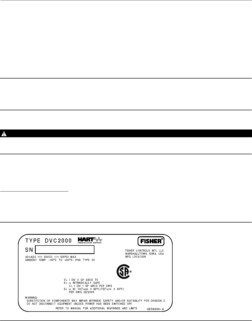
Refer to figure 24 for a typical DVC2000 CSA approval nameplate and figure 25 for installation drawing GE12444.
Figure 24. Typical CSA Nameplate

Quick Start Guide
D103203X012
DVC2000 Digital Valve Controller
April 2014
34
Figure 25. CSA Installation Drawing
GE12444‐C
EQUIPMENT SHALL BE INSTALLED IN ACCORDANCE WITH THE CANADIAN ELECTRICAL CODE (CEC) PART 1:
BARRIERS MUST BE CSA APPROVED WITH ENTITY PARAMETERS AND ARE TO BE INSTALLED IN
ACCORDANCE WITH THE MANUFACTURER'S I.S. INSTALLATION INSTRUCTIONS.
THE ENTITY CONCEPT ALLOWS INTERCONNECTION OF INTRINSICALLY SAFE APPARATUS TO ASSOCIATED
APPARATUS, NOT SPECIFICALLY EXAMINED IN SUCH COMBINATION. THE CRITERIA FOR INTERCONNECTION IS
THAT THE VOLTAGE (Vmax) AND THE CURRENT (Imax) OF THE INTRINSICALLY SAFE APPARATUS MUST BE
EQUAL TO OR GREATER THAN THE VOLTAGE (Voc) AND CURRENT (Isc) DEFINED BY THE ASSOCIATED
APPARATUS. IN ADDITION, THE SUM OF THE MAXIMUM UNPROTECTED CAPACITANCE (Ci) AND INDUCTANCE
(Li) OF EACH INTRINSICALLY SAFE APPARATUS, AND THE INTERCONNECTING WIRING, MUST BE LESS THAN
THE ALLOWABLE CAPACITANCE (Ca) AND INDUCTANCE (La) DEFINED BY THE ASSOCIATED APPARATUS. IF
THESE CRITERIA ARE MET, THEN THE COMBINATION MAY BE CONNECTED.
FORMULAS - Vmax > Voc, Imax > Isc, Ci + Ccable < Ca, Li + Lcable < La
ENTITY PARAMETERS FOR EACH I.S. CIRCUIT ARE AS FOLLOWS:
WHERE MULTIPLE IS CIRCUITS ARE USED:
EACH I.S. CIRCUIT MUST BE SHIELDED TWISTED PAIR CABLE.
I.S. CIRCUITS MUST ENTER ENCLOSURE VIA CONDUIT ENTRIES
AS SPECIFIED IN DETAIL 1.
CABLE INSULATION AND SHIELD MUST EXTEND TO WITHIN
PARTITIONED AREA (SEE DETAIL 1).
XMTR, LS1, AND LS2 CIRCUITS ARE OPTIONAL.
IF HAND‐HELD COMMUNICATOR OR MULTIPLEXOR IS USED, IT MUST
BE CSA CERTIFIED WITH ENTITY PARAMETERS AND INSTALLED PER
THE MANUFACTURER'S CONTROL DRAWING.
HAZARDOUS LOCATION NON‐HAZARDOUS LOCATION
CLASS I, DIV. 1, GROUPS A,B,C,D,
CLASS I, ZONE 0, GROUP IIC
DVC2000
XMTR
MAIN
LS1
LS2
XMTR
MAIN
LS1
LS2
CSA APPROVED
BARRIER
CSA APPROVED
BARRIER
CSA APPROVED
BARRIER
CSA APPROVED
BARRIER
PARTITIONED AREA
DETAIL 1
CIRCUIT
XMTR
MAIN
LS1
LS2
IMAX(Ii)
100mA
130mA
76mA
76mA
VMax (Ui)
28Vdc
30Vdc
16Vdc
16Vdc
Li
0 mH
0.55 mH
0 mH
0 mH
PMAX
1W
1W
1W
1W
Ci
5nF
10.5nF
5nF
5nF
THE APPARATUS ENCLOSURE CONTAINS ALUMINUM
AND IS CONSIDERED TO CONSTITUTE A POTENTIAL
RISK OF IGNTION BY IMPACT OR FRICTION. CARE
MUST BE TAKEN DURING INSTALLATION AND USE TO
PREVENT IMPACT OR FRICTION.
WARNING
FM
Special Conditions of Use
Intrinsically Safe, Non‐Incendive
The apparatus enclosure contains aluminum and is considered to constitute a potential risk of ignition by impact or
friction. Care must be taken into account during installation and use to prevent impact or friction.
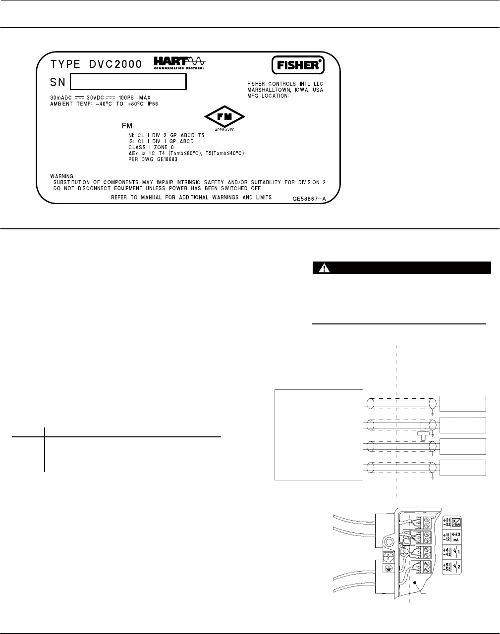
Refer to figure 26 for a typical DVC2000 FM approval nameplate and figure 27 for installation drawing GE10683.
Quick Start Guide
D103203X012
DVC2000 Digital Valve Controller
April 2014
35
Figure 26. Typical FM Nameplate
Figure 27. FM Installation Drawing
GE10683‐D
HAZARDOUS LOCATION NON‐HAZARDOUS LOCATION
CLASS I, DIV. 1, GROUPS A,B,C,D
CLASS I ZONE 0 Aex ia IIC
DVC2000 XMTR
MAIN
LS1
LS2
FM APPROVED
BARRIER
XMTR
MAIN
LS1
LS2
PARTITIONED AREA
DETAIL 1
INSTALLATION MUST BE IN ACCORDANCE WITH THE NATIONAL ELECTRICAL CODE (NEC)
AND ANSI/ISA RP12.6.
BARRIERS MUST BE CONNECTED PER MANUFACTURER'S INSTALLATION INSTRUCTIONS.
THE ENTITY CONCEPT ALLOWS INTERCONNECTION OF INTRINSICALLY SAFE
APPARATUS TO ASSOCIATED APPARATUS, NOT SPECIFICALLY EXAMINED IN
SUCH COMBINATION. THE CRITERIA FOR INTERCONNECTION IS THAT THE
VOLTAGE (Vmax) AND THE CURRENT (Imax) OF THE INTRINSICALLY SAFE
APPARATUS MUST BE EQUAL TO OR GREATER THAN THE VOLTAGE (Voc) AND
CURRENT (Isc) DEFINED BY THE ASSOCIATED APPARATUS. IN ADDITION, THE
SUM OF THE MAXIMUM UNPROTECTED CAPACITANCE (Ci) AND INDUCTANCE
(Li) OF EACH INTRINSICALLY SAFE APPARATUS, AND THE INTERCONNECTING
WIRING, MUST BE LESS THAN THE ALLOWABLE CAPACITANCE (Ca) AND
INDUCTANCE (La) DEFINED BY THE ASSOCIATED APPARATUS. IF THESE
CRITERIA ARE MET, THEN THE COMBINATION MAY BE CONNECTED.
FORMULAS - Vmax > Voc, or Vt, Ci + Ccable < Ca, Pi > Po, or Pt
Imax > Isc, or It, Li + Lcable < La
ENTITY PARAMETERS FOR EACH I.S. CIRCUIT ARE AS FOLLOWS:
WHERE MULTIPLE IS CIRCUITS ARE USED:
EACH I.S. CIRCUIT MUST BE SHIELDED TWISTED PAIR CABLE.
I.S. CIRCUITS MUST ENTER ENCLOSURE VIA CONDUIT ENTRIES
AS SPECIFIED IN DETAIL 1.
CABLE INSULATION AND SHIELD MUST EXTEND TO WITHIN PARTITIONED
AREA (SEE DETAIL 1).
XMTR, LS1, AND LS2 CIRCUITS ARE OPTIONAL.
CLASS I, DIV 2 APPLICATIONS MUST BE INSTALLED AS SPECIFIED IN NEC ARTICLE 501‐4(B).
EQUIPMENT AND FIELD WIRING IS NON‐INCENDIVE WHEN CONNECTED TO APPROVED
BARRIERS WITH ENTITY PARAMETERS.
MAXIMUM SAFE AREA VOLTAGE SHOULD NOT EXCEED 250 Vrms.
RESISTANCE BETWEEN BARRIER GROUND AND EARTH GROUND MUST BE LESS THAN ONE OHM.
IF HAND‐HELD COMMUNICATOR OR MULTIPLEXOR IS USED, IT MUST BE FM APPROVED
WITH ENTITY PARAMETERS AND INSTALLED PER THE MANUFACTURER'S CONTROL DRAWING.
CIRCUIT
XMTR
MAIN
LS1
LS2
IMAX(Ii)
100mA
130mA
76mA
76mA
VMax (Ui)
28Vdc
30Vdc
16Vdc
16Vdc
Li
0 mH
0.55 mH
0 mH
0 mH
PMAX
1W
1W
1W
1W
Ci
5nF
10.5nF
5nF
5nF
FM APPROVED
BARRIER
FM APPROVED
BARRIER
FM APPROVED
BARRIER
THE APPARATUS ENCLOSURE CONTAINS ALUMINUM
AND IS CONSIDERED TO CONSTITUTE A POTENTIAL
RISK OF IGNTION BY IMPACT OR FRICTION. CARE
MUST BE TAKEN DURING INSTALLATION AND USE TO
PREVENT IMPACT OR FRICTION.
WARNING
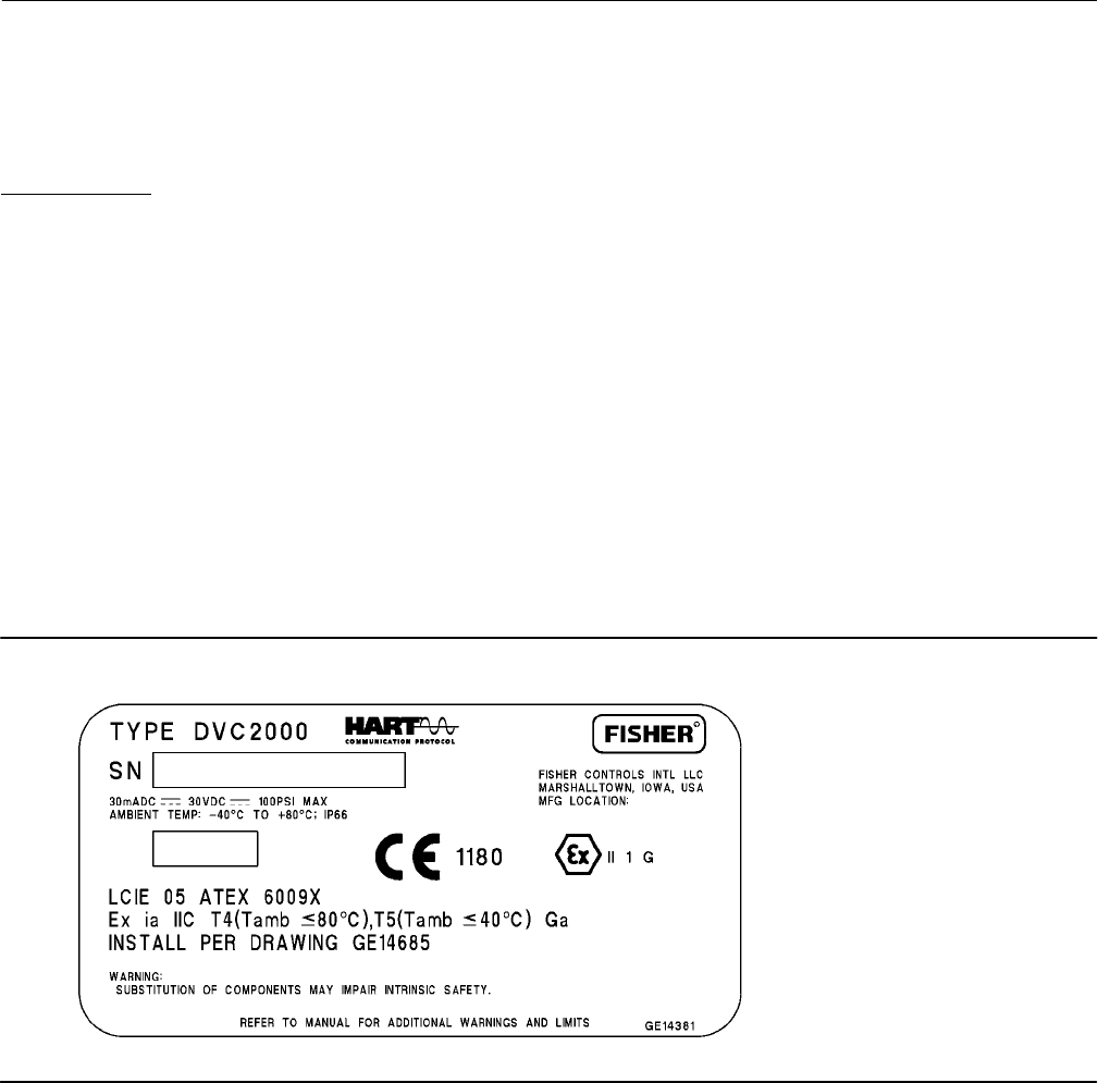
Quick Start Guide
D103203X012
DVC2000 Digital Valve Controller
April 2014
36
ATEX
Special Conditions for Safe Use
Intrinsically Safe
The equipment is an intrinsically safe equipment. It can be mounted in hazardous area.
The terminal blocks can be only connected to certified intrinsically safe equipments and these combinations must be
compatible as regard intrinsic safety rules.
The equipment shall be connected in accordance with manufacturer's installation instructions in drawing GE14685
(figure 29).
The equipment must not be submitted to mechanical impacts or frictions.
Temperature Classification:
T4 at Ta ≤ 80_C
T5 at Ta ≤ 40_C
Refer to figure 28 for a typical DVC2000 ATEX approval nameplate.
Figure 28. Typical ATEX Nameplate
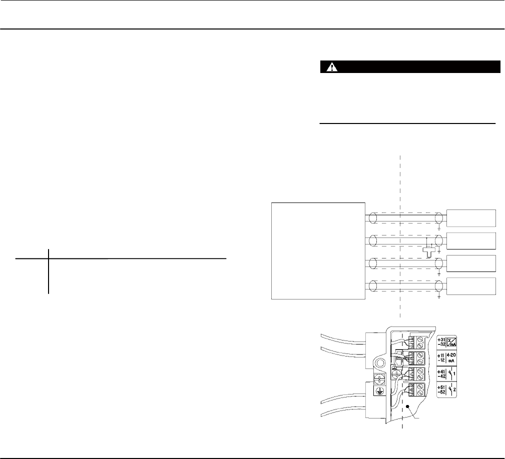
Quick Start Guide
D103203X012
DVC2000 Digital Valve Controller
April 2014
37
Figure 29. ATEX Installation Drawing
GE14685‐C
INSTALLATION MUST BE IN ACCORDANCE WITH THE NATIONAL WIRING PRACTICES OF
THE COUNTRY IN USE.
BARRIERS MUST BE CONNECTED PER MANUFACTURER'S INSTALLATION INSTRUCTIONS.
INTRINSICALLY SAFE APPARATUS MAY BE CONNECTED TO ASSOCIATED APPARATUS NOT
SPECIFICALLY EXAMINED IN SUCH COMBINATION. THE CRITERIA FOR INTERCONNECTION
IS THAT THE VOLTAGE (Ui) AND THE CURRENT (Ii) OF THE INTRINSICALLY SAFE APPARATUS
MUST BE EQUAL TO OR GREATER THAN THE VOLTAGE (Uo) AND CURRENT (Io) DEFINED BY
THE ASSOCIATED APPARATUS. IN ADDITION, THE SUM OF THE MAXIMUM
UNPROTECTED CAPACITANCE (Ci) AND INDUCTANCE (Li) OF EACH INTRINSICALLY
SAFE APPARATUS, AND THE INTERCONNECTING WIRING, MUST BE LESS THAN
THE ALLOWABLE CAPACITANCE (Co) AND INDUCTANCE (Lo) DEFINED BY THE
ASSOCIATED APPARATUS. IF THESE CRITERIA ARE MET, THEN THE
COMBINATION MAY BE CONNECTED.
FORMULASUi > Uo
Ii > Io
Ci + Ccable < Co
Li + Lcable < Lo
Pi > Po
ENTITY PARAMETERS FOR EACH I.S. CIRCUIT ARE AS FOLLOWS:
WHERE MULTIPLE IS CIRCUITS ARE USED:
EACH I.S. CIRCUIT MUST BE SHIELDED TWISTED PAIR CABLE.
I.S. CIRCUITS MUST ENTER ENCLOSURE VIA CONDUIT ENTRIES
AS SPECIFIED IN DETAIL 1.
CABLE INSULATION AND SHIELD MUST EXTEND TO WITHIN PARTITIONED
AREA (SEE DETAIL 1).
XMTR, LS1, AND LS2 CIRCUITS ARE OPTIONAL.
RESISTANCE BETWEEN BARRIER GROUND AND EARTH GROUND MUST BE LESS THAN ONE
OHM.
IF HAND‐HELD COMMUNICATOR OR MULTIPLEXOR IS USED, IT MUST BE APPROVED
WITH ENTITY PARAMETERS AND INSTALLED PER THE MANUFACTURER'S CONTROL
DRAWING.
HAZARDOUS LOCATION NON‐HAZARDOUS LOCATION
ZONE 0, GROUP IIC
DVC2000
XMTR
MAIN
LS1
LS2
I.S. APPROVED
BARRIER
XMTR
MAIN
LS1
LS2
PARTITIONED AREA
DETAIL 1
CIRCUIT
XMTR
MAIN
LS1
LS2
IMAX(Ii)
100mA
130mA
76mA
76mA
VMax (Ui)
28Vdc
30Vdc
16Vdc
16Vdc
Li
0 mH
0.55 mH
0 mH
0 mH
PMAX
1W
1W
1W
1W
Ci
5nF
10.5nF
5nF
5nF
I.S. APPROVED
BARRIER
I.S. APPROVED
BARRIER
I.S. APPROVED
BARRIER
THE APPARATUS ENCLOSURE CONTAINS ALUMINUM
AND IS CONSIDERED TO CONSTITUTE A POTENTIAL
RISK OF IGNTION BY IMPACT OR FRICTION. CARE
MUST BE TAKEN DURING INSTALLATION AND USE TO
PREVENT IMPACT OR FRICTION.
WARNING
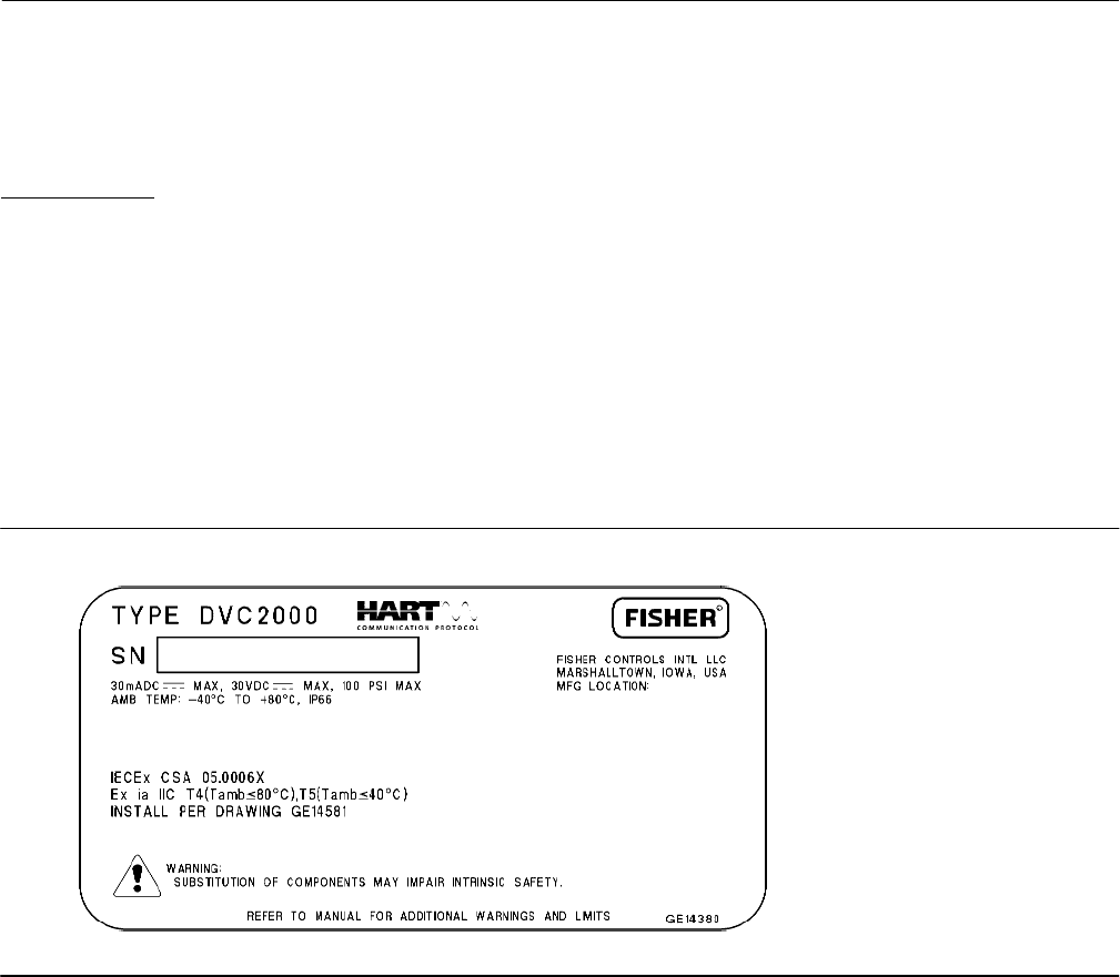
Quick Start Guide
D103203X012
DVC2000 Digital Valve Controller
April 2014
38
IECEx
Conditions of Certification
Intrinsically Safe
This equipment shall be connected in accordance with the manufacturer's installation instructions (drawing GE14581,
figure 31) to intrinsic safety barriers that satisfy the following parameters for each set of terminals.
Main 4-20 mA: Ui = 30 V, Ii = 130 mA, Pi = 1W, Li = 0.55 mH, Ci = 10.5 nF
XMTR circuit: Ui = 28 V, Ii = 100 mA, Pi = 1W, Li = 0 mH, Ci = 5 nF
Limit Switch 1 (LS1): Ui = 16 V, Ii = 76 mA, Pi = 1W, Li = 0 mH, Ci = 5 nF
Limit Switch 2 (LS2): Ui = 16 V, Ii = 76 mA, Pi = 1W, Li = 0 mH, Ci = 5 nF
Refer to figure 30 for a typical DVC2000 IECEx approval nameplate.
Figure 30. Typical IECEx Nameplate
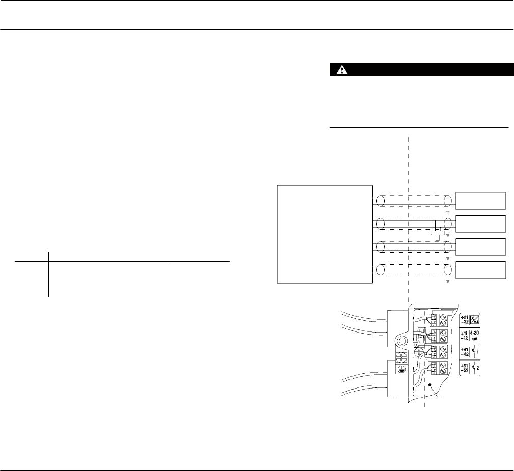
Quick Start Guide
D103203X012
DVC2000 Digital Valve Controller
April 2014
39
Figure 31. IECEx Installation Drawing
GE14581‐C
INSTALLATION MUST BE IN ACCORDANCE WITH THE NATIONAL WIRING PRACTICES OF THE
COUNTRY IN USE.
BARRIERS MUST BE CONNECTED PER MANUFACTURER'S INSTALLATION INSTRUCTIONS.
INTRINSICALLY SAFE APPARATUS MAY BE CONNECTED TO ASSOCIATED
APPARATUS NOT SPECIFICALLY EXAMINED IN SUCH COMBINATION. THE CRITERIA
FOR INTERCONNECTION IS THAT THE VOLTAGE (Ui) AND THE CURRENT (Ii) OF THE
INTRINSICALLY SAFE APPARATUS MUST BE EQUAL TO OR GREATER THAN THE
VOLTAGE (Uo) AND CURRENT (Io) DEFINED BY THE ASSOCIATED APPARATUS. IN
ADDITION, THE SUM OF THE MAXIMUM UNPROTECTED CAPACITANCE (Ci) AND
INDUCTANCE (Li) OF EACH INTRINSICALLY SAFE APPARATUS, AND THE
INTERCONNECTING WIRING, MUST BE LESS THAN THE ALLOWABLE
CAPACITANCE (Co) AND INDUCTANCE (Lo) DEFINED BY THE
ASSOCIATED APPARATUS. IF THESE
CRITERIA ARE MET, THEN THE COMBINATION MAY BE CONNECTED.
FORMULASUi > Uo
Ii > Io
Ci + Ccable < Co
Li + Lcable < Lo
Pi > Po
ENTITY PARAMETERS FOR EACH I.S. CIRCUIT ARE AS FOLLOWS:
WHERE MULTIPLE I.S. CIRCUITS ARE USED:
EACH I.S. CIRCUIT MUST BE SHIELDED TWISTED PAIR CABLE.
I.S. CIRCUITS MUST ENTER ENCLOSURE VIA CONDUIT ENTRIES
AS SPECIFIED IN DETAIL 1.
CABLE INSULATION AND SHIELD MUST EXTEND TO WITHIN PARTITIONED
AREA (SEE DETAIL 1).
XMTR, LS1, AND LS2 CIRCUITS ARE OPTIONAL.
RESISTANCE BETWEEN BARRIER GROUND AND EARTH GROUND MUST BE LESS THAN ONE OHM.
IF HAND‐HELD COMMUNICATOR OR MULTIPLEXOR IS USED, IT MUST BE APPROVED
WITH ENTITY PARAMETERS AND INSTALLED PER THE MANUFACTURER'S CONTROL DRAWING.
HAZARDOUS LOCATION NON‐HAZARDOUS LOCATION
ZONE 0, GROUP IIC
DVC2000
XMTR
MAIN
LS1
LS2
I.S. APPROVED
BARRIER
I.S. APPROVED
BARRIER
I.S. APPROVED
BARRIER
XMTR
MAIN
LS1
LS2
PARTITIONED AREA
DETAIL 1
CIRCUIT
XMTR
MAIN
LS1
LS2
IMAX(Ii)
100mA
130mA
76mA
76mA
VMax (Ui)
28Vdc
30Vdc
16Vdc
16Vdc
Li
0 mH
0.55 mH
0 mH
0 mH
PMAX
1W
1W
1W
1W
Ci
5nF
10.5nF
5nF
5nF
I.S. APPROVED
BARRIER
THE APPARATUS ENCLOSURE CONTAINS ALUMINUM
AND IS CONSIDERED TO CONSTITUTE A POTENTIAL
RISK OF IGNTION BY IMPACT OR FRICTION. CARE
MUST BE TAKEN DURING INSTALLATION AND USE TO
PREVENT IMPACT OR FRICTION.
WARNING

Quick Start Guide
D103203X012
DVC2000 Digital Valve Controller
April 2014
40
Emerson Process Management
Marshalltown, Iowa 50158 USA
Sorocaba, 18087 Brazil
Chatham, Kent ME4 4QZ UK
Dubai, United Arab Emirates
Singapore 128461 Singapore
www.Fisher.com
The contents of this publication are presented for informational purposes only, and while every effort has been made to ensure their accuracy, they are not
to be construed as warranties or guarantees, express or implied, regarding the products or services described herein or their use or applicability. All sales are
governed by our terms and conditions, which are available upon request. We reserve the right to modify or improve the designs or specifications of such
products at any time without notice.
E 2004, 2014. Fisher Controls International LLC. All rights reserved.
Neither Emerson, Emerson Process Management, nor any of their affiliated entities assumes responsibility for the selection, use or maintenance
of any product. Responsibility for proper selection, use, and maintenance of any product remains solely with the purchaser and end user.
Fisher, FIELDVUE, PlantWeb, ValveLink, and Tri‐Loop are marks owned by one of the companies in the Emerson Process Management business unit of
Emerson Electric Co. Emerson Process Management, Emerson, and the Emerson logo are trademarks and service marks of Emerson Electric Co. HART is a
mark owned by the HART Communication Foundation. All other marks are the property of their respective owners.
