Emerson Fisher Hp And Eh Data Sheet
2015-03-30
: Emerson Emerson-Fisher-Hp-And-Eh-Data-Sheet-680686 emerson-fisher-hp-and-eh-data-sheet-680686 emerson pdf
Open the PDF directly: View PDF ![]() .
.
Page Count: 28
www.Fisher.com
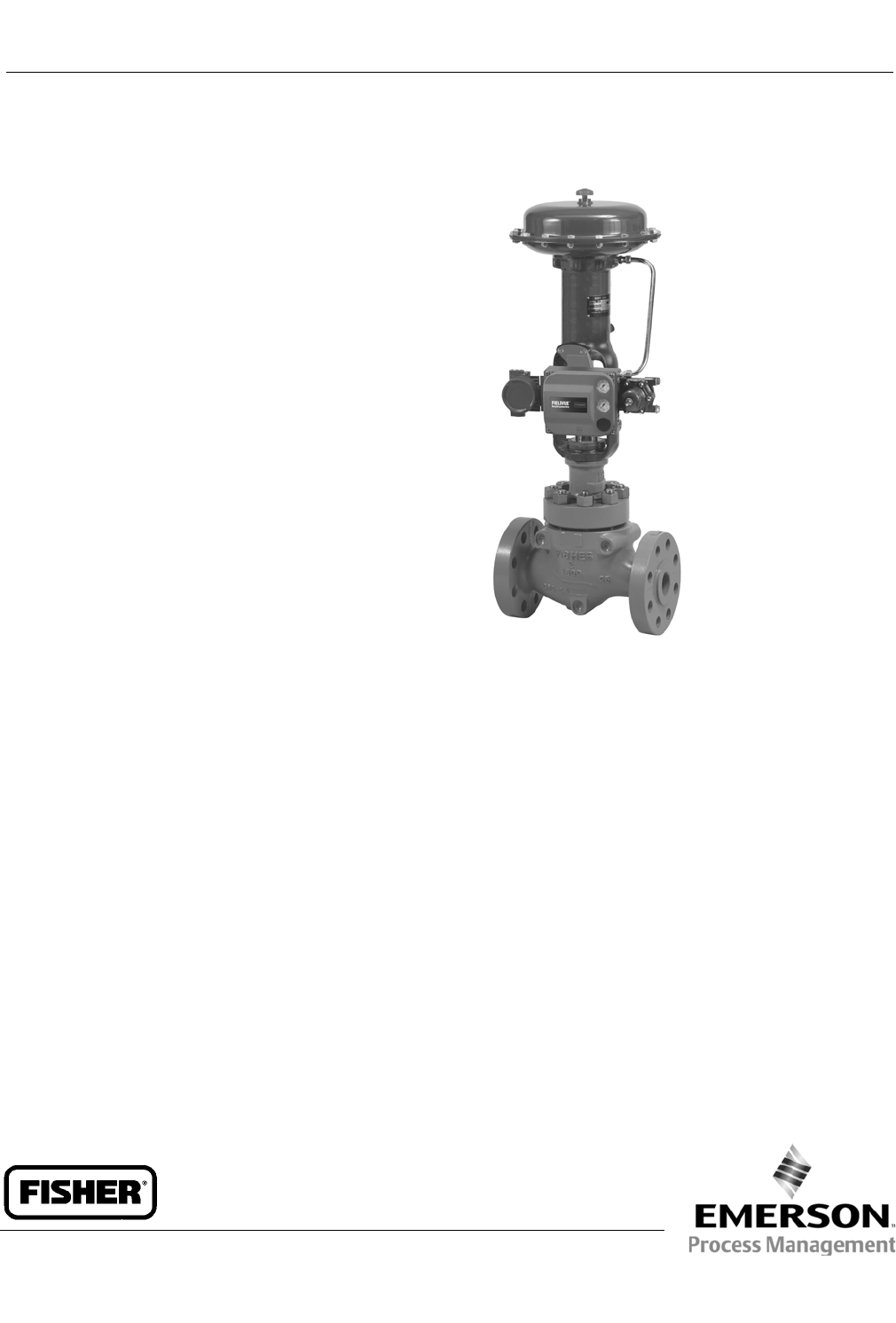
FisherrHP Series Control Valves
HP (Globe Valve)
HPA (Angle Valve)
Balanced High-Temperature Trim
Balanced Tight Shutoff Trim
Unbalanced Trim
Fisher HP Series control valves are single-port,
high-pressure, globe-or angle-style valves with metal
seats, cage guides, and push-down-to-close valve plug
action.
These valves are designed for high-pressure
applications in process control industries such as
power generation, hydrocarbon production, chemical
processing, and refining.
HP Series valves have NACE compliant materials
available. Extra valve body wall thickness provides a
safety margin of protection against erosion, as well as
extra protection against corrosion due to chemical
attack. Because these valves feature a thicker valve
body wall, they are available in higher intermediate
ratings with weld-end fittings.
Unless otherwise noted, all NACE references are to
NACE MR0175-2002 and MR0103.
Balanced
High-Temperature Trim
HPD and HPAD
These valves use a balanced valve plug with graphite
piston rings and are well suited for general applications
with process temperatures in excess of 232_C(450_F),
where extremely tight shutoff is not required.
X0183-1
FISHER HP VALVE WITH 667 ACTUATOR AND FIELDVUE™
DVC6200 DIGITAL VALVE CONTROLLER
Balanced Tight Shutoff
Trim
HPT and HPAT
These valves use a balanced valve plug and offer
excellent shutoff with process temperatures below
232_C(450_F). The temperature limits of HPT can be
extended above 232_C(450_F) to 316_C(600_F) by
using PEEK (PolyEtherEtherKetone) anti-extrusion rings
in combination with a spring-loaded PTFE seal. The
PEEK anti-extrusion rings expand to help close off the
clearance gaps on the plug outside diameter and the
cage inside diameter where the PTFE seal may extrude
at high temperatures and pressures.
HP Valve
D101635X012
Product Bulletin
51.2:HP
October 2014

HP Valve
D101635X012
Product Bulletin
51.2:HP
October 2014
2
Specifications
Available Configurations(1) and Valve Sizes
See table 1
Common Characteristics: Designed according to: J
ASME B16.34 Valve-Flanges, Threaded and Welding
End and JANSI/ISA-75.08.06
End Connections Styles(1)
See table 1
Maximum Inlet Pressure and Temperature(1,2)
Flanged, Socketwelding, or Buttwelding: Consistent
with CL900, 1500, and 2500 according to ASME
B16.34, unless limited by maximum pressure drop or
material temperature capabilities
In addition, both steel HP and HPA valves with BWE
and SWE connections have increased
pressure/temperature ratings as shown in table 3
Maximum Pressure Drop(1)
Valve with Standard Cage: Seefigure12
Valve with Cavitrol™ III Cage: 149 bar (2160 psi) for
two-stage and 207 bar (3000 psi) for three-stage
cage. Consult Fisher Bulletin 80.2:030, Cavitrol III
One-,Two-,andThree-Stage trims,for more
information
Valve with Whisper Trim™ III Cage:
J0.6 nP/P1maximum for levels A1 and A3
J0.75 nP/P1maximum for levels B1 and B3
J0.85 nP/P1maximum for levels C1 and C3
J0.99 nP/P1maximum for levels D1 and D3
Valve with WhisperFlo™ Trim:
JLevels X, Y, and Z: 0.94 nP/P1maximum. If
greater than 0.94 nP/P1, consult your Emerson
Process Management sales office
Shutoff Classifications
See table 4
Construction Materials
Valve Body and Bonnet:
JWCC steel(3),JWC9 Cr-Mo steel(3),JC12A
chrome-moly alloy, JCF8M,CD3MN,and
CD3MWCuN stainless steel, and JLCC for low
temperature service
Trim: See table 12
Other Parts: See table 7
Consult your Emerson Process Management sales
office for special trim and valve body material
availability.
Material Temperature Capabilities(1)
HPD,HPAD,HPS,andHPAS:Up to 566_C (1050_F)
unless limited (see tables 7 or 12 and figure 12)
HPT and HPAT: Up to 232_C(450_F) unless limited
(see tables 7 or 12 and figure 12)
Flow Characteristics(4)
Standard Cages: JLinear, Jequal percentage,
Jmodified equal percentage(5)
Cavitrol III and Whisper Trim III Cages: Linear
Micro-Flute: Equal percentage
Micro-Flat: Linear
Micro-Form: JEqual percentage, Jmodified equal
percentage
Flow Direction
Standard Cage
JHPD, HPAD: Normally flow down
JHPS, HPAS: Normally flow up(6)
JHPAS Micro
-
Flat: Flow down
JHPS, HPAS Micro
-
Form: Flow up only
JHPT, HPAT: Normally flow down
Cavitrol III Cage: Flow down
Whisper Trim III Cage: Flow up
Flow Coefficients
See table 2 and also Fisher Catalog 12
Noise Levels
See Fisher Catalog 12, Section 3 for noise prediction
methods
Port Diameters, Valve Plug Travel, and
Stem Diameters
Seetables5,8,9,and11
- continued -

HP Valve
D101635X012
Product Bulletin
51.2:HP
October 2014
3
Specifications (continued)
Bonnet Style and Mounting(1)
JStandard Bonnet: Seefigure1
Yoke Temperature Limit: Standard bonnet with cast
iron yoke is limited to 537_C (1000_F)
JOptional Style 1–Extension Bonnet: Used for NPS
1 and 2 valves for CL900 or 1500, and NPS 1 valves for
CL2500 (see figures 14 and 15)
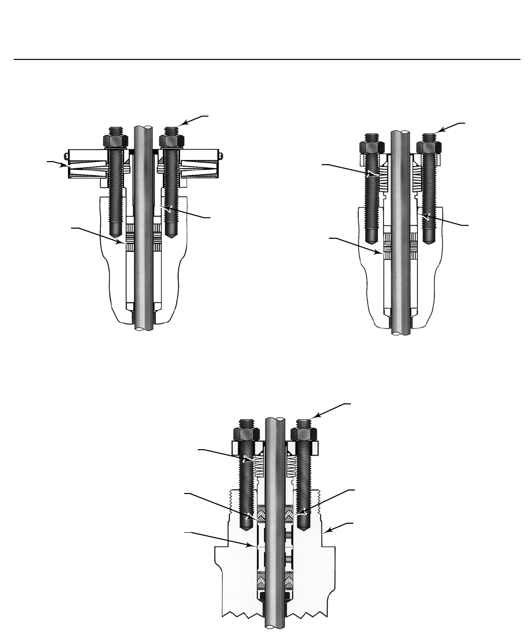
Packing Arrangements
JSingle, JDouble, and JLeakoff standard
packing, or optional JENVIRO-SEAL™ and
JHIGH-SEAL packing systems. See figure 4. Also see
bulletin 59.1:061, ENVIRO-SEAL and HIGH-SEAL
Packing System for Sliding-Stem Valves
Yoke Boss Diameter for Actuator Mounting
See tables 5 and 10, and figures 13, 14, and 15
Approximate Weight
See table 6
Options(1)
JValves with weld-end fittings have increased
pressure/temperature ratings, called intermediate
ratings(7), JClass V(6) shutoff for HPT and HPAT to
316_C(600_F) using PEEK anti-extrusion rings(8),J
Class V shutoff for HPD and HPAD to 593_C (1100_F)
using C-seal trim, Jexpanded ends(7) for NPS 4 and
6 valves (NPS 4 valves are available with NPS 6 ends,
andNPS6valvesareavailablewithNPS8ends),J
lubricator or lubricator/isolating valve(7)
1. The pressure/temperature limits in this bulletin and any applicable standard limitations should not be exceeded.
2. EN (or other valve body material) ratings and end connections can usually be supplied; consult your Emerson Process Management sales office.
3. SA-105 and SA-182-F22 are used for CL2500 HPA valves instead of WCC and WC9.
4. Special characterized cages are available. Contact your Emerson Process Management sales office.
5. Modified equal percentage characteristic is equal percentage for the first 75% of travel, then opens quickly for additional capacity.
6. HPS valves may be used flow down for on-off service only. HPAS valves may be used for flow down in erosive service.
7. For more information contact your Emerson Process Management sales office.
8. Required for all boiler feedwater applications.
Table of Contents
Balanced High-Temperature Trim 1................
Balanced Tight Shutoff Trim 1....................
Specifications 2................................
Unbalanced Trim 4.............................
Expanded Ends 4...............................
Cavitrol, Whisper Trim
and WhisperFlo Cages 4.......................
Features 4.....................................
Material Selection Guidelines 7...................
Installation 7..................................
Packing 9.....................................
Trim Selection Guidelines 17.....................
Trim Material Combinations 19...................
Pressure/Temperature Limits for
Trim Material Combinations 22.................
Dimensions 23.................................
HP Valve
D101635X012
Product Bulletin
51.2:HP
October 2014
4
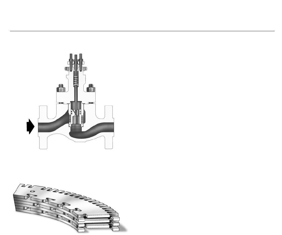
Figure 1. Fisher HPD Valve Assembly (NPS 2 to 6)
W5815A-1
FLOW
Figure 2. Typical WhisperFlo Trim Cut Section View
for Fisher HP Valve
W7065
Unbalanced Trim
HPS and HPAS
These valves have an unbalanced plug and provide
excellent shutoff.
Expanded Ends
Expanded ends are available on the NPS 4 and 6 CL900
and 1500 HP valves. The NPS 4 HP valve body is offered
with NPS 6 ends. The NPS 6 valve body is offered with
NPS 8 ends. Both flanged and buttweld end valve
bodies are offered with expanded ends.
Cavitrol III, Whisper Trim
III, and WhisperFlo Cages
To eliminate cavitation damage in a properly-sized
valve, a Cavitrol III cage is available with HPS, HPAS,
HPT, and HPAT control valves.
To help attenuate aerodynamic noise in gaseous
service, Whisper Trim III and WhisperFlo (figure 2)
cages are available with HPD, HPAD, HPS, HPAS, HPT,
and HPAT control valves. Contact your Emerson
Process Management sales office for more
information.
Features
Valve Plug Stability– Rugged cage guiding provides
increased valve plug stability, which reduces
vibration and mechanical noise.
Full Pressure Drop Capability–Rugged construction
allows full pressure drop capability in HP series
valves.
Spiral-Wound Gaskets for Excellent Sealing Under
All Service Conditions–Premium materials are used
in the construction of spiral-wound gaskets for HP
Series valves. These premium materials, which
make up the standard spiral-wound gaskets, are
N06600 (alloy 600)/graphite or N07750
(alloy X750)/graphite.
Compliance with the Clean Air Act–Optional
ENVIRO-SEAL packing systems (figure 4) provide an
improved stem seal to help prevent the loss of
valuable process fluid or emission of hazardous
process fluid. The ENVIRO-SEAL packing systems
featurePTFEorgraphiteULF.
Piping Economy–The availability of expanded end
connections on NPS 4 and 6 HP valves may
eliminate the need for line swages while
accommodating oversized piping arrangements.
Quick Change Trim–Maintenance is simple and can
easily be performed using common tools. Trim
components can be quickly removed and changed
with no need for special tools.

HP Valve
D101635X012
Product Bulletin
51.2:HP
October 2014
5
Standard Hard Trim Materials–Thecage,valveplug,
and other trim parts are manufactured from
hardened materials. This standard feature provides
excellent wear resistance.
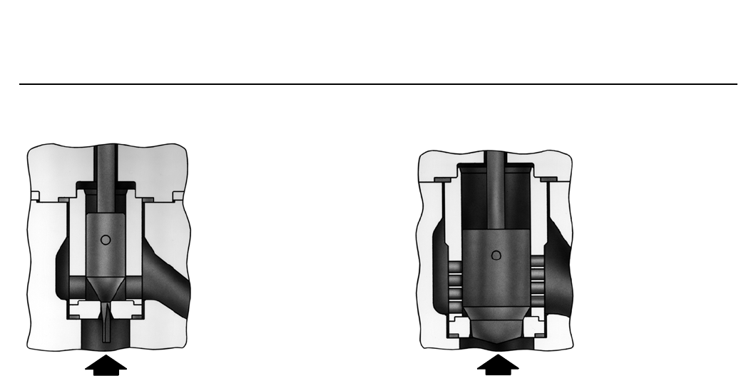
Control of Low Flow Rates/Tight
Shutoff–Micro-Flute and Micro-Form valve plugs
(figures 6 and 7, respectively) provide superb
rangeability in high-pressure, low-flow applications,
while maintaining tight shutoff (table 4). A choice of
several restricted port diameters helps to match
valve body capacity to required flow, to provide
necessary control with fulltravel,andtoprevent
throttling near the seat.
In low-flow applications where cavitation damage
may occur, the Micro-Flat valve plug can be used
with a special Cavitrol III cage. Contact your
Emerson Process Management sales office for more
information.
Increased Pressure/Temperature Ratings– HP Series
valves with weld-end fittings have increased
pressure/temperature ratings, called intermediate
ratings, as defined in ASME B16.34. The extra
strength of these valves allows ratings higher than
the standard CL900 or 1500 ratings specified in
B16.34. Contact your Emerson Process
Management sales office for further information on
intermediate ratings.
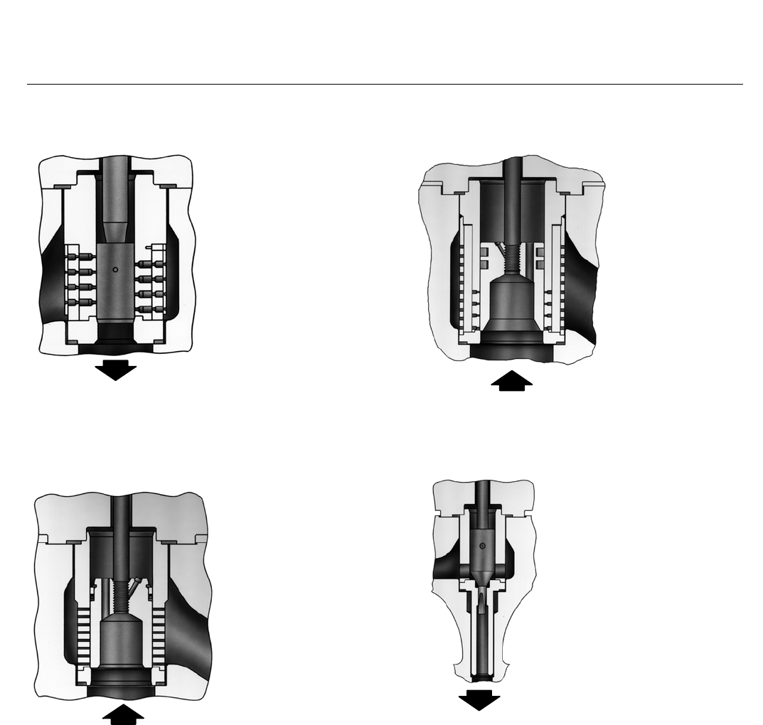
Trim Interchangeability–Cavitrol III, Whisper Trim
III, and WhisperFlo trims (figures 8, 9, and 10) are
interchangeable with standard trims.
Smooth Control at High Pressure Drops–Available
on NPS 2 through 6 valves, balanced trim provides
smooth control at high pressure drops.
High-Temperature Capability with Class V
Shutoff–Use of C-seal trim (see figure 5) permits
Class V shutoff up to 593_C (1100_F) for HPD
valves.
Sour Service Trims Available–Long-lasting, erosion-
and corrosion-resistant trims are available for
control of sour service. These trims are offered with
either a standard cage, a Cavitrol III cage, a Whisper
Trim III cage, or WhisperFlo trim. Spiral-wound
gasket construction is standard.
Table 1. Available Constructions
DESIGN VALVE SIZE,
NPS PRESSURE RATING
VALVE BODY MATERIAL AND END CONNECTION STYLE(1, 2)
WCC, WC9, LCC, C12A, CF8M, CD3MN, and
CD3MWCuN Stainless Steel
Cast Valves
SA-105, SA-182-F22, SA-182-F316, S31803
F51, and S32760 F55 forged SST (for forged
steel HPA CL2500 angle valves)
RF or RTJ Flanged,
Butt Weld, and Socket Weld(3) Socket Weld
HPAD 2to8 CL900 and 1500 X---
2CL2500 --- X
HPAS 1to2 CL900 and 1500 X---
CL2500 --- X
HPAT 2to8 CL900 and 1500 X---
2CL2500 --- X
HPD 2to6 CL900 and 1500 X---
2CL2500 X---
HPS 1to3 CL900 and 1500 X---
1to2 CL2500 X---
HPT 2to6 CL900 and 1500 X---
2CL2500 X---
X = Available Construction.
1. End connection style abbreviations: RF -Raised Face, RTJ -Ring Type Joint.
2. EN (or other valve body material) ratings and end connections can usually be supplied; consult your Emerson Process Management sales office.
3. Socket Weld available on NPS 1, 1-1/2, and 2 only.
HP Valve
D101635X012
Product Bulletin
51.2:HP
October 2014
6
Table 2. Typical Flow Coefficients(1)
Valve Size,
NPS Valve Style Characteristic Maximum Cv
1HP CL1500 Modified Equal
Percentage 17.1
2HP CL1500 Linear 52.2
3HP CL1500 Linear 121
4HP CL1500 Linear 201
6HP CL1500 Linear 425
1HPA CL1500 Modified Equal
Percentage 19.5
2HPA CL1500 Linear 64.3
1HPA CL2500 Modified Equal
Percentage 14.3
2HPA CL2500 Linear 47.4
1. See the section titled Coefficients in this bulletin and also Catalog 12 for a
complete listing of flow coefficients.
Table 3. Increased Pressure/Temperature Ratings for
Steel Valves with BWE and SWE Connections(1)
Valve Type
Valve
Size,
NPS
Pressure Rating
Intermediate
Rating
(ASME
B16.34)
Globe Valves
1CL900 and 1500 1675
CL2500 2800
2CL900 and 1500 1694
3CL1500 1578
4CL1500 2017
6CL1500 1876
1. Contact your Emerson Process Management sales office for further information on
intermediate ratings.
Table 4. Shutoff Classifications per ANSI/FCI 70-2 and IEC 60534-4
Valve Design Port Diameter, mm (Inches) ANSI/FCI and IEC Leakage Class
HPD, HPAD
47.6 (1.875) II
58.7 (2.3125) to 92.1 (3.625) II -Standard
III -Optional
111.1 (4.375) and larger III -Standard
IV -Optional
HPD, HPAD
w/ C-seal trim
Valve Size, NPS Port Diameter, mm (Inches) Cage Style ANSI/FCI and IEC Leakage Class
HPD HPAD
3 4 73 (2.875)
Eq.%,Mod.Eq.%,
Linear (std. cage),
Linear (Whisper III, A1, B1)
V-Standard
to 593_C (1100_F)
(for port diameters from 73 mm
[2.875 inch] through 136.5 mm [5.375
inch]
with optional C-seal trim)
IV -Optional
(for port diameters 73 mm [2.875
inch] through 136.5 mm [5.375 inch]
4 6
73 (2.875) Linear (Whisper III, D3)
92.1 (3.625)
Eq.%,Mod.Eq.%,
Linear (std. cage),
Linear (Whisper III, A1, B3, C3)
6 8
111.1 (4.375) Linear (Whisper III, D3)
136.5 (5.375)
Eq.%,Mod.Eq.%,
Linear (std. cage),
Linear (Whisper III, A1, B3, C3)
HPS, HPAS, HPT, HPAT All
Cavitrol III and Micro-Flat V-Standard
Micro-Form, Micro-Flute, Eq. %,
Mod Eq. %, Linear, Whisper III
IV -Standard
V-Optional
HPS and HPT w/ TSO
(Tight Shutoff trim) See table 5 See table 5
TSO -Optional
TSO is not an ANSI/FCI or IEC leakage
class.
Valves with TSO trim are factory tested
to a more stringent Fisher test
requirement of no leakage at time of
shipment.
Test medium is water.
Specify service Pwhenordering.
Test procedure is ANSI/FCI Class V test
procedure B
HPT and HPAT w/ PEEK(1) Anti-Extrusion
Rings 47.6 (1.875) to 136.5 (5.375) All
V-Standard (to 316_C [600_F])
IV -Optional (47.6 mm [1.875 inch]
through
136.5 mm [5.375 inch] ports)
1. PEEK (PolyEtherEtherKetone), required for all boiler feedwater applications.

HP Valve
D101635X012
Product Bulletin
51.2:HP
October 2014
7
Material Selection
Guidelines
Usethefollowingstepsasaguidelinefortheselection
of materials:
1. Determine the pressure/temperature rating of the
valve body size and material required. Inlet pressure
and temperature must always be limited by the
applicable ASME pressure/temperature rating.
2. SelectthedesiredtrimstylefromtheAvailable
Configurations specification and from table 4, Shutoff
Classifications.
3. Select desired materials from tables 7, 8, 11, and 12
and figure 12. The temperature capabilities
determined from figure 12 may be further limited by
the temperature capabilities of materials selected
from tables 7 and 12. Refer to figure 12 to determine
pressure drop limits of the valve body-trim
combinations selected.
Installation
The valve must be installed so flow through the valve is
as indicated by the flow direction arrow on the valve
body. Consideration should be given to installing an
upstream strainer, especially if the valve uses a Cavitrol
III cage, Whisper Trim III, or WhisperFlo trim.
Overall dimensions are shown in figures 13, 14, and
15. Face-to-face dimensions are in compliance with
ANSI/ISA-75.08.06. Actual end connection dimensions
conform to ASME B16.25 for buttwelding ends and to
ASME B16.5 for flanged ends.
HP Valve
D101635X012
Product Bulletin
51.2:HP
October 2014
8
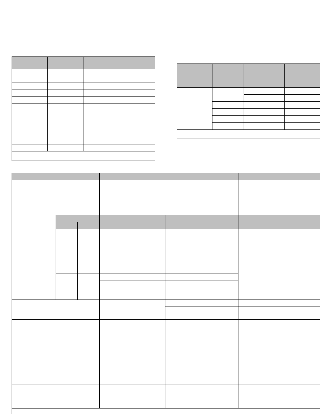
Table 5. Port Diameters, Valve Plug Travel, Yoke Boss Diameters for TSO (Tight Shutoff) Trim
VALVE
TYPE TRIM MAX TRAVEL YOKE BOSS SIZE PORT DIAMETER CV
REDUCTION
AT 100%
TRAVEL(1)
UNBALANCE
AREA
Nominal Actual TSO
mm Inch mm Inch mm Inch mm Inch Inch2
Balanced Plugs–Flow Down Only
HPT
NPS 3(2) CAV III 3-Stage 63.5 2.5 90 3-9/16 47.6 1.875 42.9 1.6875 5% 0.031
HPT
NPS 4 CAV III 3-Stage 76.2 390
127
3-9/16
573.0 2.875 68.3 2.6875 2% 0.047
HPT
NPS 6
CAV III 3-Stage 102 490
127
3-9/16
5116 4.5625 111 4.375 0% 0.080
Standard 76.2 390
127
3-9/16
5137 5.375 132 5.1875 4% 0.206
Unbalanced Plugs–Flow Down Only
HPS
NPS 2 CAV III 3-Stage 50.8 290 3-9/16 25.4 126.2 0.8125 0% 0.785
1. This column lists the percent reduction of published maximum CVof the trim listed in the TRIM column.
2. Not available with 5-inch yoke boss.
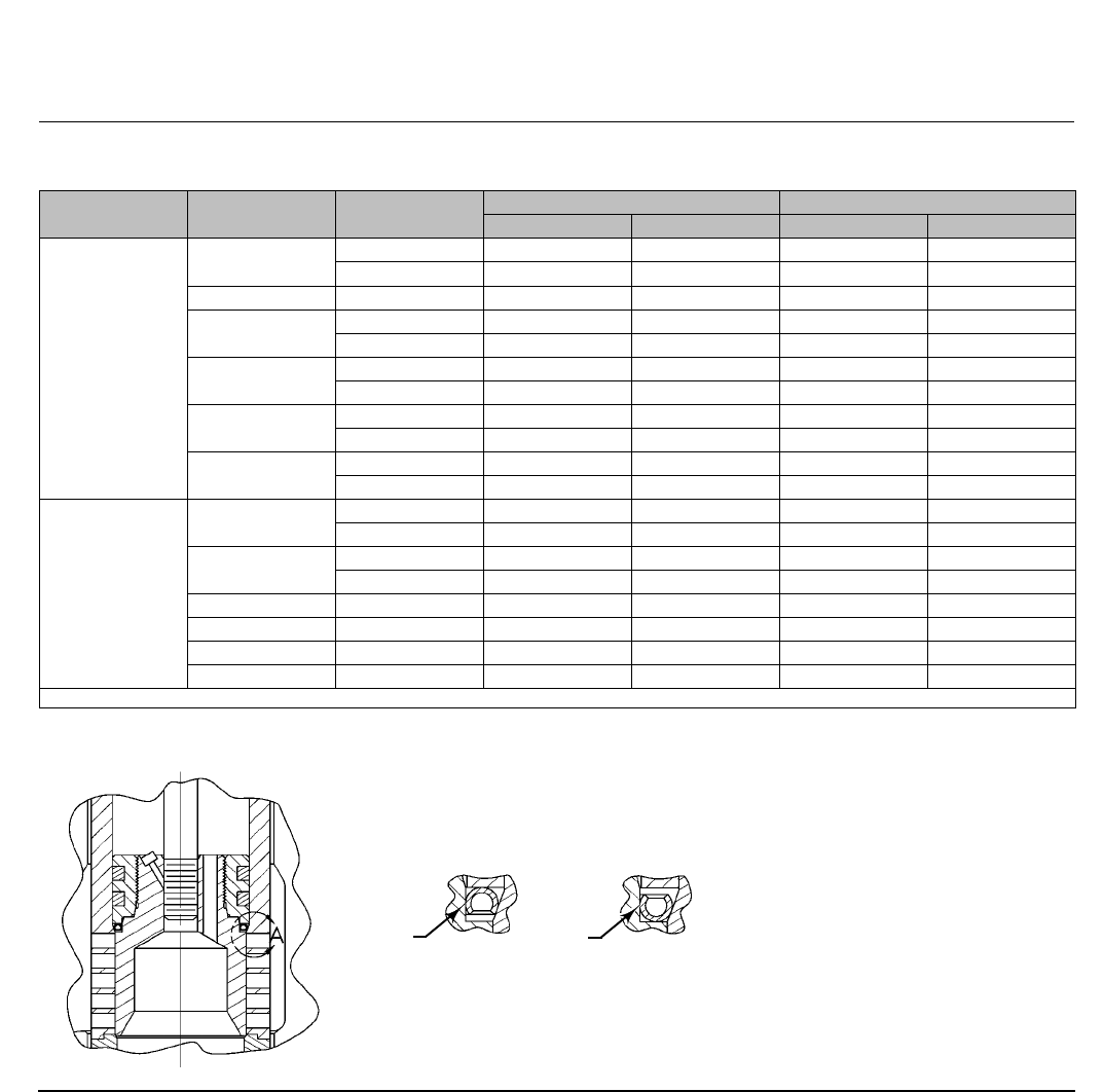
Figure 3. Typical Balanced TSO Trim
VALVE PLUG
SEAL
TSO PROTECTED
SOFT SEAT SEAL
W7020-1
HP Valve
D101635X012
Product Bulletin
51.2:HP
October 2014
9
Figure 4. ENVIRO-SEAL and HIGH-SEAL Packing Systems
TYPICAL HIGH-SEAL PACKING SYSTEM
WITH GRAPHITE ULF PACKING
W5803-3
SPRINGS
ANTI-
EXTRUSION
RING
LANTERN
RING
PACKING
BOX
STUDS
PACKING
RING
VALVE
BONNET
TYPICAL ENVIRO-SEAL PACKING SYSTEM
WITH PTFE PACKING
TYPICAL ENVIRO-SEAL PACKING SYSTEM
WITH GRAPHITE ULF PACKING
W8533-1
PACKING
BOX
STUD
FOLLOWER
PACKING
SPRING
W8532-1
FOLLOWER
PACKING
BOX
STUD
PACKING
SPRINGS
HP Valve
D101635X012
Product Bulletin
51.2:HP
October 2014
10
Table 6. Approximate Weights (Valve and Bonnet Assemblies)
VALVE TYPE VALVE SIZE,
NPS PRESSURE RATING KILOGRAMS POUNDS
Flg SWE, BWE Flg SWE, BWE
Globe Valves
1CL900 and 1500 42 38 93 85
CL2500 45 34 100 76
1-1/2 x 2 CL2500 --- 34 --- 76
2CL900 and 1500 72 52 158 115
CL2500 104 74 229 164
3CL900 125 --- 276 ---
CL1500 129 97 284 213
4CL900 230 --- 507 ---
CL1500 249 201 548 444
6CL900 511 --- 1127 ---
CL1500 557 455 1228 1003
Angle Valves
1CL900 and 1500 40 36 88 80
CL2500 --- 72(1) --- 160(1)
2CL900 and 1500 69 50 153 110
CL2500 --- 109(1) --- 240(1)
3CL1500 123 78 272 173
4CL1500 181 117 399 258
6CL1500 357 202 788 445
8CL1500 648 405 1428 893
1. Only SWE is available for CL2500.
Figure 5. C-seal Trim
C-SEAL
METAL
PLUG
SEAL(1)
1. Reverse the orientation of the C-seal plug seal for proper shutoff when valve is used in a process with different fluid flow direction.
Note:
FLOW DOWN FLOW UP
VIEW A
37B1399-A
C-SEAL
METAL
PLUG
SEAL(1)

HP Valve
D101635X012
Product Bulletin
51.2:HP
October 2014
11
Table 7. Construction Materials and Temperature Capabilities for Parts Other than Valve Body and Trim
PART MATERIAL TEMPERATURE CAPABILITIES
_C_F
Valve plug stem S20910 -198 to 593 -325 to 1100
S32760 -51 to 316 -60 to 600
HPD
piston ring
Graphite (FMS 17F27)
-46 to 427 (to 482
for nonoxidizing
service)
-50 to 800 (to 900
for nonoxidizing
service)
Graphite (FMS 17F39)
-46 to 537 (to 593
for nonoxidizing
service)
-50 to 1000 (to 1100
for nonoxidizing
service)
Spring-loaded
HPT or HPAT
valve plug seal
Backup ring S41600 (416 SST) -29 to 427 -20 to 800
S31600 (316 SST) -198 to 593 -325 to 1100
Retaining ring S30200 (302 SST)
N07750 (NACE) -254 to 593 -425 to 1100
Seal ring PTFE with N10276 Spring -73 to 232(5) -100 to 450(5)
Anti-extrusion
rings PEEK (PolyEtherEtherKetone) -73 to 316 -100 to 600
Cage gasket N06600/Graphite -240 to 593 -400 to 1100
TSO protected soft seat seal Carbon-filled PTFE -73 to 232 -100 to 450
Seat ring gasket N06600/Graphite -240 to 593 -400 to 1100
Valve Body-to-
bonnet
bolting(1)
Studs
Nuts
Steel SA193-B7 (all valve body materials)
Steel SA194-2H (all valve body materials)
-29 to 427
(WCC and WC9)
-46 to 371
(LCC)
-48 to 427
(316 CF8M)(2)
-20 to 800
(WCC and WC9)
-50 to 700
(LCC)
-55 to 800
(316 CF8M)(2)
Studs
Nuts
Steel SA193-B7Mforsourservice
Steel SA194-2HM for sour service
-29 to 427 (WCC)
-46 to 371 (LCC)
-20 to 800 (WCC)
-50 to 700 (LCC)
Studs
Nuts
Steel SA193-B16 (WC9 and C12A valve body mat'ls)
Steel SA194-7-29 to 510 -20 to 950
Studs
Nuts
N07718 SST (SB637)(3)
Steel SA194-7
-29 to 566 (WC9)
-29 to 593 (C12A)
-20 to 1050 (WC9)
-20 to 1100 (C12A)
Studs
Nuts
S31600 stainless steel SA193-B8M (strain hardened)
(CF8M valve body mat'ls)(4)
S31600 stainless steel SA194-8M (CF8M valve body mat'ls)(4)
-198 to 427 -325 to 800
Studs
Nuts
S20910 SST (SA479-XM-19)(3) (CF8M valve body mat'ls)
Steel SA194-7-198 to 593 -325 to 1100
Packing
PTFE V-ring -46 to 232 -50 to 450
Graphite ribbon filament (oxidizing service to 371_C [700_F]) -254 to 537 -425 to 1000
Graphite ribbon
(high-temperature oxidizing service) 371 to 593 700 to 1100
Packing follower,
spring, or lantern ring S31600 stainless steel -254 to 593 -425 to 1100
Packing box ring S31600 stainless steel -254 to 593 -425 to 1100
Packing flange, studs, or nuts Steel -29 to 427 -20 to 800
S31600 stainless steel -198 to 593 -325 to 1100
1. Valve body materials with which these bolting materials may be used are shown in parentheses.
2. Steel studs and nuts with NCF (non-corrodingfinish)coatingareusedwithNPS4and6CF8Mvalvebodies.
3. These stud materials are not listed in ASME B16.34.
4. For valve sizes up through NPS 3.
5. If used with PEEK anti-extrusion rings, PTFE/carbon seal ring may be used in temperatures up to 316_C (600_F) for non-oxidizing service or up to 260_C (500_F) for oxidizing service.

HP Valve
D101635X012
Product Bulletin
51.2:HP
October 2014
12
Table 8. Additional Globe Valve Specifications
VALVE
SIZE,
NPS
FLOW
CHARACTERISTIC
VALVE BODY
DESIGN AND
PLUG STYLE
PORT
DIAMETER
VALVE PLUG
TRAVEL VALVE STEM DIAMETER
mm Inches mm Inches mm Inches
1
Equal
percentage
HPS w/Micro-Flute 6.4
12.7
0.25
0.5
19
19
0.75
0.75
12.7
12.7
1/2
1/2
HPS w/Micro-Form
6.4
12.7
19.1
0.25
0.5
0.75
19
19
19
0.75
0.75
0.75
12.7
12.7
12.7, 19.1
1/2
1/2
1/2, 3/4
Modified
equal percentage HPS w/Micro-Form 19.1
25.4
0.75
1
29
29
1.125
1.125
12.7, 19.1
12.7, 19.1
1/2,3/4
1/2, 3/4
Linear (cage style:
Cavitrol III, 2-stage) HPS 22.2 0.875 38 1.5 12.7, 19.1 1/2, 3/4
2
Equal
percentage
HPS w/Micro-Form
6.4
12.7
19.1
0.25
0.5
0.75
19
19
19
0.75
0.75
0.75
12.7
12.7
12.7, 19.1
1/2
1/2
1/2, 3/4
HPS 47.6 1.875 29 1.125 12.7, 19.1, 25.4(1) 1/2, 3/4, 1(1)
Linear (cage style:
Std)
HPS, HPD, HPT 47.6 1.875 38 1.5 12.7, 19.1, 25.4(1) 1/2, 3/4, 1(1)
Linear (cage style:
Whisper Trim III,
level A1)
Modified
equal
percentage
HPS w/Micro-Form
25.4
31.8
38.1
1
1.25
1.5
29
29
38
1.125
1.125
1.5
12.7,19.1, 25.4
12.7, 19.1, 25.4
12.7, 19.1, 25.4
1/2, 3/4, 1
1/2, 3/4, 1
1/2, 3/4, 1
HPS, HPD, HPT 47.6 1.875 38 1.5 12.7, 19.1, 25.4(1) 1/2, 3/4, 1(1)
Linear (cage style:
Cavitrol III, 2-stage) HPT 44.5 1.75 51 212.7, 19.1 1/2, 3/4
Linear (cage style:
Cavitrol III, 3-stage) HPS 25.4 151 219.1 3/4
3
Modified equal
percentage
HPD, HPT 73 2.875 51 212.7, 19.1, 25.4 1/2, 3/4, 1
Linear (cage style:
Std)
Linear (cage style:
Whisper Trim III, level
A1, B1)
Linear (cage style:
Cavitrol III, 2-stage) HPT 63.5 2.5 64 2.5 12.7, 19.1, 25.4 1/2, 3/4, 1
Linear (cage style:
Cavitrol III, 3-stage) HPT 47.6 1.875 64 2.5 12.7, 19.1, 25.4 1/2, 3/4, 1
-continued-

HP Valve
D101635X012
Product Bulletin
51.2:HP
October 2014
13
Table 8. Additional Globe Valve Specifications (Continued)
VALVE
SIZE,
NPS
FLOW
CHARACTERISTIC
VALVE BODY
DESIGN AND
PLUG STYLE
PORT
DIAMETER
VALVE PLUG
TRAVEL VALVE STEM DIAMETER
mm Inches mm Inches mm Inches
4
Modified equal
percentage
HPD, HPT 92.1 3.625 51 219.1, 25.4 3/4, 1
Linear (cage style:
(Std)
Linear (cage style:
Whisper Trim III level
A1, A3, B3, C3)
Linear (cage style:
Whisper Trim III level
D3)
HPD, HPT 73 2.875 51 219.1, 25.4 3/4, 1
Linear (cage style:
Cavitrol III, 2-stage) HPT 87.3 3.4375 76 319.1, 25.4 3/4, 1
Linear (cage style:
Cavitrol III, 3-stage) HPT 73 2.875 76 319.1, 25.4 3/4, 1
6
Modified equal percentage(2)
HPD, HPT 136.5 5.375 76 319.1, 25.4, 31.8 3/4, 1, 1-1/4
Linear (cage style: Std)
Linear (cage style: Whisper
Trim III, level A1, B3, C3) HPD, HPT 136.5 5.375 76 325.4, 31.8 1, 1-1/4
Linear (cage style: Whisper
Trim III, level D3) HPD, HPT 111.1 4.375 76 325.4, 31.8 1, 1-1/4
Linear (cage style:
Cavitrol III, 2-stage) HPD, HPT 133.4 5.25 102 419.1, 25.4, 31.8 3/4, 1, 1-1/4
Linear (cage style:
Cavitrol III, 3-stage) HPD, HPT 115.9 4.5625 102 419.1, 15.4, 31.8 3/4, 1, 1-1/4
1. Available only with HPS valve.
2. The first 75% is equal percentage.

HP Valve
D101635X012
Product Bulletin
51.2:HP
October 2014
14
Table 9. Valve Stem Travels for CL2500 Globe Valves
VALVE
SIZE,
NPS
VALVE DESIGN / PLUG STYLE CHARACTERISTIC
PORT DIAMETER MAXIMUM VALVE STEM TRAVEL
mm Inches mm Inches
1HPS / Micro-Form or Micro-Flute
Equal Percentage 6.4, 9.5, 12.7,
19.1, 25.4
0.25, 0.375, 0.5,
0.75, 1 19.1 0.75
Modified Equal Percentage 6.4, 9.5, 12.7,
19.1, 25.4
0.25, 0.375, 0.5,
0.75, 1 25.4 1
2
HPS / Micro-Form
Equal Percentage 6.4, 19.1, 25.4,
31.8
0.25, 0.75, 1,
1.25 19.1 0.75
Modified Equal Percentage 6.4, 19.1, 25.4,
31.8
0.25, 0.75, 1,
1.25 28.6 1.125
HPS / Micro-Form Equal Percentage 38.1 1.5 28.6 1.125
Modified Equal Percentage 38.1 1.5 38.1 1.5
HPS
Linear 47.6 1.875 25.4 1
Equal Percentage
Modified Equal Percentage 47.6 1.875 28.6 1.125
HPD, HPT
Linear 47.6 1.875 25.4 1
Equal Percentage
Modified Equal Percentage 47.6 1.875 28.6 1.125
Table 10. Globe and Angle Valve Yoke Boss and Valve Stem Diameter Combinations(1)
VALVE
SIZE,
NPS
STANDARD DIAMETERS OPTIONAL DIAMETERS
mm Inches mm Inches
Stem Yoke Boss Stem Yoke Boss Stem Yoke Boss Stem Yoke Boss
112.7 71 0.5 2-13/16 19.1 90 0.75 3-9/16
212.7
19.1
71
90
0.5
0.75
2-13/16
3-9/16 25.4 127 1 5
319.1 90 0.75 3-9/16 12.7
25.4
71
127
0.5
1
2-13/16
5
419.1 90 0.75 3-9/16 25.4 127 1 5
625.4
31.8
127
127
1
1.25
5
519.1 71 0.75 3-9/16
8(2) 25.4
31.8
127
127
1
1.25
5
519.1 71 0.75 3-9/16
1.Seetables8,9,and11forvalvestemdiameters available for specific constructions.
2. Angle valve construction only (HPAD, HPAT).

HP Valve
D101635X012
Product Bulletin
51.2:HP
October 2014
15
Table 11. Additional Angle Valve Specifications
VALVE
SIZE,
NPS
FLOW
CHARACTERISTIC
VALVE BODY
DESIGN AND
PLUG STYLE
FLOW
DIRECTION
PORT
DIAMETER
VALVE PLUG
TRAVEL VALVE STEM DIAMETER
mm Inches mm Inches mm Inches
1
Equal
percentage
HPAS w/Micro-Flute Up(2)
6.4
9.5
12.7
0.25
0.375
0.5
19
19
19
0.75
0.75
0.75
12.7
12.7
12.7
1/2
1/2
1/2
HPAS w/Micro-Form Up
6.4
12.7
19.1
0.25
0.5
0.75
19
19
19
0.75
0.75
0.75
12.7
12.7
12.7, 19.1
1/2
1/2
1/2, 3/4
HPAS, equal
percentage characterized cage Down 19.1 0.75 19 0.75 19.1 3/4
Modified
equal
percentage
HPAS w/Micro-Form Up
12.7
19.1
25.4
0.5
0.75
1
29
29
29
1.125
1.125
1.125
12.7
12.7, 19.1
12.7, 19.1
1/2
1/2, 3/4
1/2, 3/4
HPAS Down 19.1 0.75 29 1.125 19.1 3/4
Linear (cage
style: Std) HPAS w/ Micro-Flat Down
9.5
12.7
19.1
0.375
0.5
0.75
19
19
19
0.75
0.75
0.75
12.7
12.7
19.1
1/2
1/2
3/4
Linear (cage style:
Cavitrol III, 2-stage) HPAS, HPAD Down 22.2 0.875 38 1.5 12.7, 19.1 1/2, 3/4
2
Equal
percentage
HPAS w/Micro-Flute Up(2)
6.4
9.5
12.7
0.25
0.375
0.5
19
19
19
0.75
0.75
0.75
12.7
12.7
12.7
1/2
1/2
1/2
HPAS w/Micro-Form Up
6.4
12.7
19.1
25.4
0.25
0.5
0.75
1
19
19
19
19
0.75
0.75
0.75
0.75
12.7
12.7
12.7, 19.1
12.7, 19.1, 25.4
1/2
1/2
1/2, 3/4
1/2, 3/4, 1
HPAS, equal
percentage characterized cage Down
19.1
25.4
31.8
38.1
0.75
1
1.25
1.5
19
19
19
29
0.75
0.75
0.75
1.125
19.1
19.1
25.4
25.4
3/4
3/4
1
1
HPAS Up 47.6 1.875 29 1.125 12.7, 19.1, 25.4 1/2, 3/4, 1
HPAT, HPAD Down 47.6 1.875 29 1.125 12.7, 19.1 1/2, 3/4
Modified equal
percentage
HPAS w/Micro-Form Up
25.4
31.8
38.1
1
1.25
1.5
29
29
38
1.125
1.125
1.5
12.7, 19.1, 25.4
12.7, 19.1, 25.4
12.7, 19.1, 25.4
1/2, 3/4, 1
1/2, 3/4, 1
1/2, 3/4, 1
HPAS, equal
percentage characterized cage Down
19.1
25.4
31.8
38.1
0.75
1
1.25
1.5
29
29
29
38
1.125
1.125
1.125
1.5
19.1
19.1
25.4
25.4
3/4
3/4
1
1
HPAS Up 47.6 1.875 38 1.5 12.7, 19.1, 25.4 1/2, 3/4, 1
HPAT, HPAD Down 47.6 1.875 38 1.5 12.7, 19.1 1/2, 3/4
Linear (cage
style: std) HPAS w/Micro-Flat Down 25.4 129 1.125 19.1 3/4
Linear (cage
style: std)
HPAS Up 47.6 1.875 38 1.5 12.7, 19.1, 25.4 1/2, 3/4, 1
HPAT, HPAD Down 47.6 1.875 38 1.5 12.7, 19.1 1/2, 3/4
Linear (cage style:
Whisper III, level A1) HPAS, HPAT, HPAD Up 47.6 1.875 38 1.5 12.7, 19.1, 25.4(1) 1/2, 3/4, 1(1)
Linear (cage style:
Cavitrol III, 2-stage) HPAT Down 44.5 1.75 51 212.7, 19.1 1/2, 3/4
Linear (cage style:
Cavitrol III, 3-stage) HPAS Down 25.4 151 219.1 3/4
-continued-

HP Valve
D101635X012
Product Bulletin
51.2:HP
October 2014
16
Table 11. Additional Angle Valve Specifications (continued)
VALVE
SIZE,
NPS
FLOW
CHARACTERISTIC
VALVE BODY
DESIGN AND
PLUG STYLE
FLOW
DIRECTION
PORT
DIAMETER
VALVE PLUG
TRAVEL VALVE STEM DIAMETER
mm Inches mm Inches mm Inches
3
Equal percentage
HPAT, HPAD
Down 47.6 1.875 29 1.125 12.7, 19.1 1/2, 3/4
Modified equal
percentage Down 47.6 1.875 38 1.5 12.7, 19.1 1/2, 3/4
Linear (cage style: Std) Down
47.6 1.875 38 1.5 12.7, 19.1 1/2, 3/4
Linear (cage style:
Whisper III, level A1) Up
Linear (cage style:
Cavitrol III, 2-stage) HPAT Down 44.5 1.75 51 212.7, 19.1 1/2, 3/4
Linear (cage style:
Cavitrol III, 3-stage) HPAS Down 25.4 151 219.1 3/4
4
Equal percentage
HPAT, HPAD
Down 73 2.875 38 1.5 12.7, 19.1, 25.4 1/2, 3/4, 1
Modified equal
percentage Down
73 2.875 51 212.7, 19.1, 25.4 1/2, 3/4, 1
Linear (cage style: Std) Down
Linear (cage style:
Whisper III, level A1,
B1)
Up
Linear (cage style:
Cavitrol III, 2-stage) HPAT
Down 64 2.5 64 2.5 12.7, 19.1, 25.4 1/2, 3/4, 1
Linear (cage style:
Cavitrol III, 3-stage) Down 47.6 1.875 64 2.5 12.7, 19.1, 25.4 1/2, 3/4, 1
6
Equal percentage
HPAT, HPAD
Down 92.1 3.625 38 1.5 19.1, 25.4 3/4, 1
Modified equal
percentage Down
92.1 3.625 51 219.1, 25.4 3/4, 1
Linear (cage style: Std) Down
Linear (cage style:
Whisper III, level A1,
A3, B3, C3)
Up
Linear (cage style:
Whisper III, level D3) Up 73 2.875 51 219.1, 25.4 3/4, 1
Linear (cage style:
Cavitrol III, 2-stage) HPAT
Down 87.3 3.4375 76 319.1, 25.4 3/4, 1
Linear (cage style:
Cavitrol III, 3-stage) Down 73 2.875 76 319.1, 25.4 3/4, 1
8
Equal percentage
HPAT, HPAD
Down 136.5 5.375 64 2.5 19.1, 25.4, 31.8 3/4, 1, 1-1/4
Modified equal
percentage Down 136.5 5.375 76 319.1, 25.4, 31.8 3/4, 1, 1-1/4
Linear (cage style: Std) Down
Linear (cage style:
Whisper III, level A1,
A3, B3, C3)
Up 136.5 5.375 76 325.4, 31.8 1, 1-1/4
Linear (cage style:
Whisper III, level D3) Up 111.1 4.375 76 325.4, 31.8 1, 1-1/4
Linear (cage style:
Cavitrol III, 2-stage) HPAT
Down 133.4 5.25 102 419.1, 25.4, 31.8 3/4, 1, 1-1/4
Linear (cage style:
Cavitrol III, 3-stage) Down 115.9 4.5625 102 419.1, 25.4, 31.8 3/4, 1, 1-1/4
1. Available only with HPAS valves.
2. Micro-Flutes (1 flute and 0.5 inch port 2 flute) may be used flow down in flashing and erosive service.
HP Valve
D101635X012
Product Bulletin
51.2:HP
October 2014
17
Figure 6. Fisher HPS Trim with Micro-Flute Valve Plug
W5816-1
FLOW
Trim Selection Guidelines
Refer to the following descriptions as a guideline for
the selection of appropriate trims.
Trim 201A– Trim 201A is the standard trim for
carbon steel and alloy steel valve body materials.
This trim is recommended for general or severe
service applications up to 343_C(650_F) or 427_C
(800_F) depending on valve construction. Typical
applications for this trim include services in boiler
feedwater, water, nonsour hydrocarbons, and
steam.
Trims 202 and 202H– Trims 202 and 202H are
designed for use in high temperature applications
up to 566_C (1050_F). Trim 202H includes special
tolerances required for larger sized HPD and HPAD
constructions, as indicated in table 12, at operating
temperatures above 343_C (650_F).
Figure 7. Fisher HPS Trim with Micro-Form Valve Plug
FLOW
W5817-1
Trim 203– Trim 203 is the standard trim for
stainless steel valve body materials and should only
be used with stainless steel valve body materials.
This trim meets the metallurgical requirements of
NACE MR0175-2002 and can be used in applications
up to 593_C (1100_F)
Trim 204– Trim 204 is used in sour or moderately
corrosive services. This trim meets the metallurgical
requirements of NACE MR01752002 and can be
used with carbon steel and alloy steel valve body
materials.
Trim 210– Provides a S31600 CoCr-A hardfaced
valve plug, which can be easily weld repaired. The
S17400 H1075 cage in this trim also allows it to be
usedinanHPTorHPATconstruction.
Trim 211– Trim 211 is the standard trim for C12A
valve body materials and should only be used with
C12A valve body materials. C12A should only be
used when the pressure and temperature
capabilities for WC9 valve body materials are not
acceptable.
HP Valve
D101635X012
Product Bulletin
51.2:HP
October 2014
18
Figure 8. NPS 2 Fisher HPSTrim withCavitrolIII
3-Stage Cage
FLOW
W5818-1
Figure 9. Fisher HPT Trim with Whisper Trim III Level
A1 Cage (also available in HPD [NPS 2-6] and HPS
[NPS 2 and 3])
FLOW
W5952-1
C-seal Trim Description
C-seal trim is available for HPD and HPAD valves with
port diameters from 2.875 inches through 5.375
inches.
With C-seal trim, a balanced valve can achieve
high-temperature, Class V shutoff. Because the C-seal
plug seal is formed from metal (N07718 nickel alloy)
rather than an elastomer, a valve equipped with the
C-seal trim can be applied in processes with a fluid
temperature of up to 593_C (1100_F).
Figure 10. Fisher HPD Trim with Whisper Trim III
Level D Cage (also available in HPT and HPS)
FLOW
W5951-1
Figure 11. Fisher HPAS Trim with Micro-Flat Valve
Plug
FLOW
W6021-1
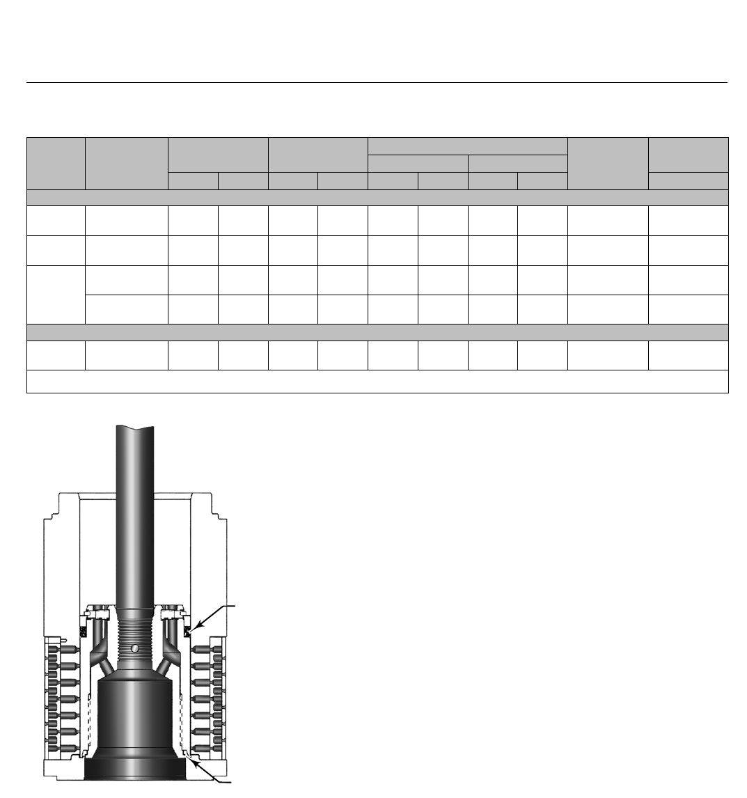
Fisher TSO (Tight Shutoff) Trim
Capabilities
TSO trim is available for HPS and HPT valves with port
diameters as defined in table 5. Also see figure 3 and
table 4.
TSO trim consists of a protected soft seat plus PEEK
anti-extrusion rings with a spring-loaded PTFE plug
seal. Used only in flow down applications, TSO trim
offers unparalleled shutoff integrity, resulting in longer
plug and seat life. For additional information contact
your Emerson Process Management sales office.

HP Valve
D101635X012
Product Bulletin
51.2:HP
October 2014
19
Table 12. Trim Material Combinations
TRIM USAGE VALVE PLUG CAGE SEAT RING VALVE BODY
MATERIAL(1)
OPERATING TEMPERATURE
RANGE(2)
_C_F
With Standard Cage
201A
HP (NPS 1-6 CL900 &
1500 & NPS 1-2
CL2500)
HPA (NPS 1-8 CL900
&1500 &NPS 1-2
CL2500)
S41600 heat-treated
for HP, HPA,
Micro-Form (HPA), and
flow down HPAS)
or
S44004 (440C SST)
heat-treated for
Micro-Flute and
Micro-Flat (HPA only)
valve plugs
S17400 (17-4SST)
H1075 heat-treated
S41600 heat-treated
or
HPA (S44004
heat-treated seat ring
for Micro-Flat
S44004 heat-treated
seat and liner)
WCC -29 to 343(8) -20 to 650(8)
LCC -29 to 343 -20 to 650
WC9 -29 to 343(8) -20 to 650(8)
202
HPD & HPS only (NPS
1-6 CL900 & 1500 &
NPS 1 to 2 CL2500)
HPAD & HPAS only
(NPS 1-8 CL900 & 1500
&NPS 1-2 CL2500)
S31600 (316 stainless
steel) with CoCr-Aseat
and guide
F22 Cr-Mo alloy steel
nitrided
S31600/CoCr-A
or
R30006 (Alloy 6) for
Micro-Flat valve plugs
R30006 seat, liner(3)
WCC -29 to 427 -20 to 800
LCC -46 to 343 -50 to 650
WC9 -29 to 566 -20 to 1050
202H(4)
HPD NPS 6 CL900 &
1500,
HPAD NPS 8 CL900 &
1500 only
S31600 (316 stainless
steel) with CoCr-Aseat
and guide
F22 Cr-Mo alloy steel
nitrided S31600/CoCr-A
WCC 260 to 427 500 to 800
LCC 260 to 343 500 to 650
WC9 260 to 566 500 to 1050
203
(NACE)(5) HP (NPS 1-6 CL900 &
1500 & NPS 1-2
CL2500)
HPA (NPS 1-8 CL900 &
1500 &NPS 1-2
CL2500)
S31600 with CoCr-A
seat and guide
S31600/hard
Cr coat
S31600/CoCr-A
or
R30006 (Alloy 6) for
Micro-Flat valve plugs
R30006 seat, liner(3)
CF8M -198 to 593(2) -325 to 1100(2)
204
(NACE)(5)
S31600 with CoCr-A
seat and guide
S17400 Double
H1150 heat-treated
S31600/CoCr-A
or
R30006 (Alloy 6) for
Micro-Flat valve plugs
R30006 seat, liner(3)
WCC -29 to 427 -20 to 800
LCC -46 to 343 -50 to 650
WC9 -29 to 427 -20 to 800
210
HP (NPS 1-6 CL900 &
1500 & NPS 1-2
CL2500)
HPA (NPS 1-8 CL900 &
1500 &NPS 1-2
CL2500)
S31600 with CoCr-A
seat and guide S17400 H1075 S31600/CoCr-A
WCC -29 to 427 -20 to 800
LCC -46 to 343 -50 to 650
WC9 -29 to 427 -20 to 800
211(9)
HPD & HPS only (NPS
1-6 CL900 & 1500 &
NPS 1 to 2 CL2500)
HPAD & HPAS only
(NPS 1-8 CL900 & 1500
&NPS 1-2 CL2500)
F91withCoCr-A
seat and guide F91 ion nitrided F91 with CoCr-A C12A -29 to 593 -20 to 1100
TC1(10) HPS & HPAS (NPS 1-2
CL900, 1500 & 2500)
S17400/tungsten
carbide insert for seat
& contour (for Micro
trims)(11)
Alloy 6
S17400/tungsten
carbide insert for seat
&bore
WCC, WC9 -29 to 232 -20 to 450
TC2(10) HPS & HPAS (NPS 1-2
CL900, 1500 & 2500)
S32550/tungsten
carbide insert for seat
& contour (for Micro
trims)(11)
Alloy 6
S32550/tungsten
carbide insert for seat
&bore
CF8M, CD3MN,
CD3MWCuN -29 to 232 -20 to 450
TC3(10) HPS & HPAS (NPS 1-2
CL900, 1500 & 2500)
N07718/tungsten
carbide insert for seat
& contour (for Micro
trims)(11)
Alloy 6
N07718/tungsten
carbide insert for seat
&bore
CW6MC -29 to 232 -20 to 450
-continued-

HP Valve
D101635X012
Product Bulletin
51.2:HP
October 2014
20
Table 12. Trim Material Combinations (continued)
TRIM USAGE VALVE PLUG CAGE SEAT RING VALVE BODY
MATERIAL(1)
OPERATING TEMPERATURE
RANGE(2)
_C_F
With Standard Cage
751 HP (NPS 1-6
CL900 & 1500)
≤1/4inchPort:
Alloy 6
>1/4inch,<3inch
Port: S31803 with
CoCr-Aseatandguide
≥3inchPort:
S31803/Ultimet
S31803/Cr Pl S31803/CoCr A CD3MN -51 to 316 -60 to 600
752 HP (NPS 1-6
CL900 & 1500)
≤1/4inchPort:
Alloy 6
>1/4inch,<3inch
Port: S32760 with
CoCr-Aseatandguide
≥3inchPort:
S32760/Ultimet
S32760/Cr Pl S32760/CoCr A CD3MWCuN -51 to 316 -60 to 600
With Cavitrol III Cage
215A
HP (NPS 1-6 CL900 &
1500 & NPS 1-2
CL2500)
HPA (NPS 1-8 CL900 &
1500 &NPS 1-2
CL2500)
S44004 heat-treated S17400
H1075 heat-treated
S42000
or
S44004 heat-treated
for CAV III Micro-Flat
only
WCC
-29 to 232(7) -20 to 450(7)
LCC
WC9
215B(6)
HP (NPS 1-6 CL900 &
1500 & NPS 1-2
CL2500)
HPA (NPS 1-8 CL900 &
1500 &NPS 1-2
CL2500)
S44004 heat-treated S17400
H1075 heat-treated
S42000
or
S44004 heat-treated
for CAV III Micro-Flat
only
WCC
-29 to 232(7) -20 to 450(7)
LCC
WC9
206
(NACE)(5)
HP (NPS 1-6 CL900 &
1500 & NPS 1-2
CL2500)
HPA (NPS 1-8 CL900 &
1500 &NPS 1-2
CL2500)
S31600 with CoCr-A
seat and guide
S17400 Double
H1150 heat-treated S31600/CoCr-A
WCC -29 to 232(7) -20 to 450(7)
LCC -46 to 232(7) -50 to 450(7)
WC9 -29 to 232(7) -20 to 450(7)
753 HP (NPS 1-6
CL900 & 1500)
≤1/4inchPort:
Alloy 6
>1/4inch,<3inch
Port: S31803 with
CoCr-Aseatandguide
≥3inchPort:
S31803/Ultimet
S32760 S31803/CoCr A CD3MN -51 to 316 -60 to 600
754 HP (NPS 1-6
CL900 & 1500)
≤1/4inchPort:
Alloy 6
>1/4inch,<3inch
Port: S32760 with
CoCr-Aseatandguide
≥3inchPort:
S32760/Ultimet
S32760 S32760/CoCr A CD3MWCuN -51 to 316 -60 to 600
-continued-

HP Valve
D101635X012
Product Bulletin
51.2:HP
October 2014
21
Table 12. Trim Material Combinations (continued)
TRIM USAGE VALVE PLUG CAGE SEAT RING VALVE BODY
MATERIAL(1)
OPERATING TEMPERATURE
RANGE(2)
_C_F
With Whisper Trim III Cage
207A
HP (NPS 1-6 CL900 &
1500 & NPS 1-2
CL2500)
HPA (NPS 1-8 CL900 &
1500 &NPS 1-2
CL2500)
S41600 heat-treated S17400
H1075 heat-treated
S41600
heat-treated
WCC
-29 to 343(8) -20 to 650(8)
LCC
WC9
207B
HP (NPS 1-6 CL900 &
1500 & NPS 1-2
CL2500
S41600 heat-treated S17400
H1075 heat-treated S31600/CoCr-A
WCC -29 to 427 -20 to 800
LCC -29 to 343 -20 to 650
WC9 -29 to 427 -20 to 800
208
HPD & HPS only (NPS
1-6 CL900 & 1500 &
NPS 1 to 2 CL2500)
HPAD&HPAS(NPS1-8
CL900 & 1500 &NPS
1-2 CL2500)
S31600 with CoCr-A
seat and guide
F22 steel
nitrided S31600/CoCr-A
WCC -29 to 427 -20 to 800
LCC -46 to 343 -50 to 650
WC9 -29 to 566 -20 to 1050
208H(4)
HPD (NPS 6 CL900 &
1500)
HPAD (NPS 8 CL900 &
1500 only)
S31600 with CoCr-A
seat and guide
F22 steel
nitrided S31600/CoCr-A
WCC -29 to 427 -20 to 800
LCC -46 to 343 -50 to 650
WC9 -29 to 566 -20 to 1050
209
(NACE)(5)
HP (NPS 1-6 CL900 &
1500 & NPS 1-2
CL2500)
HPA (NPS 1-8 CL900 &
1500 &NPS 1-2
CL2500)
S31600 with CoCr-A
seat and guide
S17400 Double
H1150 heat-treated S31600/CoCr-A
WCC -29 to 343 -20 to 650
LCC -46 to 343 -50 to 650
WC9 -29 to 343 -20 to 650
212(9)
HPD & HPS only (NPS
1-6 CL900 & 1500 &
NPS 1 to 2 CL2500)
HPAD & HPAS only
(NPS 1-8 CL900 & 1500
&NPS 1-2 CL2500)
F91withCoCr-A
seat and guide F91 ion nitrided F91 with CoCr-A C12A -29 to 593 -20 to 1100
751 HP (NPS 1-6
CL900 & 1500)
≤1/4inchPort:
Alloy 6
>1/4inch,<3inch
Port: S31803 with
CoCr-Aseatandguide
≥3inchPort:
S31803/Ultimet
S31803/Cr Pl S31803/CoCr A CD3MN -51 to 316 -60 to 600
752 HP (NPS 1-6
CL900 & 1500)
≤1/4inchPort:
Alloy 6
>1/4inch,<3inch
Port: S32760 with
CoCr-Aseatandguide
≥3inchPort:
S32760/Ultimet
S32760/Cr Pl S32760/CoCr A CD3MWCuN -51 to 316 -60 to 600
1. If using valve body/trim combinations other than those listed, consult your Emerson Process Management sales office.
2. Temperatures above 538_C (1000_F) require a non-standard CF8M body material (CF8M to FMS 20B16).
3. For HPA valves.
4. Trims 202H and 208H have valve plug tolerances for high temperature service and are used in place of trims 202 and 208 for the constructions listed when operating temperatures exceed
343_C (650_F).
5. NACE MR0175-2002.
6. Trim 215B has a S31600 valve stem instead of the standard S20910 material.
7. NPS 1 2 stage and NPS 2 3 stage HPS can be used at temperatures up to 343_C(650_F).
8.NPS1and2canbeusedattemperaturesupto427_C(800_F).
9. Trims 211 and 212 use S41000 stem instead of the standard S20910 material. S41000 is limited to 538_C (1000_F). For temperatures greater than 538_C (1000_F), S42200 stem is used.
10. Trims TC1, TC2, TC3 use S20910, S32550, and N07718 stem respectively. Use these trims for highly erosive applications.
11. Use with Micro-Form trim in HPS, Micro-Form and Micro-Flat in HPAS valves.
HP Valve
D101635X012
Product Bulletin
51.2:HP
October 2014
22
Table13.FlowingPressureDropLimitsforNPS6HPDandHPT Valves (Without Cavitrol III or Whisper Trim III
Cage)
FLOW
MEDIA
STEM
DIAMETER,
mm (INCHES)
MAXIMUM FLOWING
PRESSURE DROP
Bar PSI
Flow Down Flow Up Flow Down Flow Up
All except
boiler
feedwater
19 (3/4) 103 --- 1500 ---
25.4 (1) 172 --- 2500 ---
31.8 (1-1/4) 259 --- 3750 ---
51.8 x 31.8(1)
(2 x 1-1/4) 259 259 3750 3750
Boiler
feedwater
31.8 (1-1/4) 69 --- 1000 ---
51.8 x 31.8(1)
(2 x 1-1/4) 138 259 2000 3750
1. Requires 31.8 mm (1-1/4 inch) S20910 stem with 52.8 mm (2-inch) plug-to-stem connection.
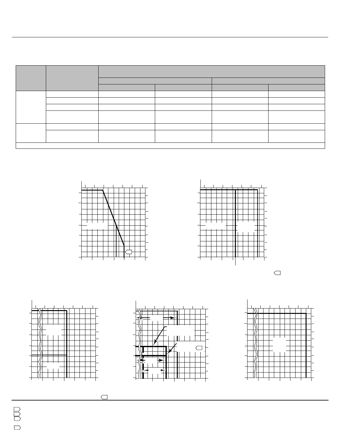
Figure 12. Pressure-Temperature Limits for Trim Material Combinations
Notes:
Use trim 207B in NPS 3, 4, 6 HP and NPS 4, 6, 8 HPA above 343_C (650_F).
NACE MR0175-2002.
Be especially careful to specify service temperature if trim 202 or 208 is selected, As different thermal expansionrates
require special plug clearances.
The limit for 2-stage NPS 1 and 2 valves is 2160 psig. For NPS 3 to 6 valves the limit is 1800 psig.
1
2
3
4
C0746-5
300
0
00
0
1000
2000
3000
5000
6000
10
4000
1200
0200 400 600
200
400
300
200
100
800400-40
FLUID TEMPERATURE, _F
FLUID TEMPERATURE,
_C
PRESSURE DROP, PSI
600 1000
PRESSURE DROP, BAR, DIFFERENTIAL
6000
0
1000
2000
3000
5000
10
4000
1200
0200 400 600
200
400
200
100
800400-40
FLUID TEMPERATURE, _F
FLUID TEMPERATURE,
_C
SOUR SERVICE APPLICATIONS (NACE)
PRESSURE DROP, PSI
600 1000
0
1000
2000
3000
5000
6000
10
4000
1200
200 400 600
200
400
300
200
100
800400
-100
FLUID TEMPERATURE, _F
FLUID TEMPERATURE,
_C
PRESSURE DROP, PSI
600 1000
0
1000
2000
3000
5000
6000
10
4000
1200
200 400 600
200
400
300
200
100
800400-20
FLUID TEMPERATURE, _F
FLUID TEMPERATURE,
_C
PRESSURE DROP, PSI
600 1000
0
1000
2000
3000
5000
6000
10
4000
1200
200 400 600
200
400
300
200
100
800400-20
FLUID TEMPERATURE, _F
FLUID TEMPERATURE,
_C
PRESSURE DROP, PSI
600 1000
-29
PRESSURE DROP, BAR, DIFFERENTIAL
PRESSURE DROP, BAR, DIFFERENTIAL
PRESSURE DROP, BAR, DIFFERENTIAL
PRESSURE DROP, BAR, DIFFERENTIAL
-29
1
-40 -40 -73
2
650
3
202,208 202H,
208H
201, 207
210
LIMIT FOR
3-STAGE
LIMIT FOR
2-STAGE
204,
209
206
206
215
4
203
211
212
HP Valve
D101635X012
Product Bulletin
51.2:HP
October 2014
23
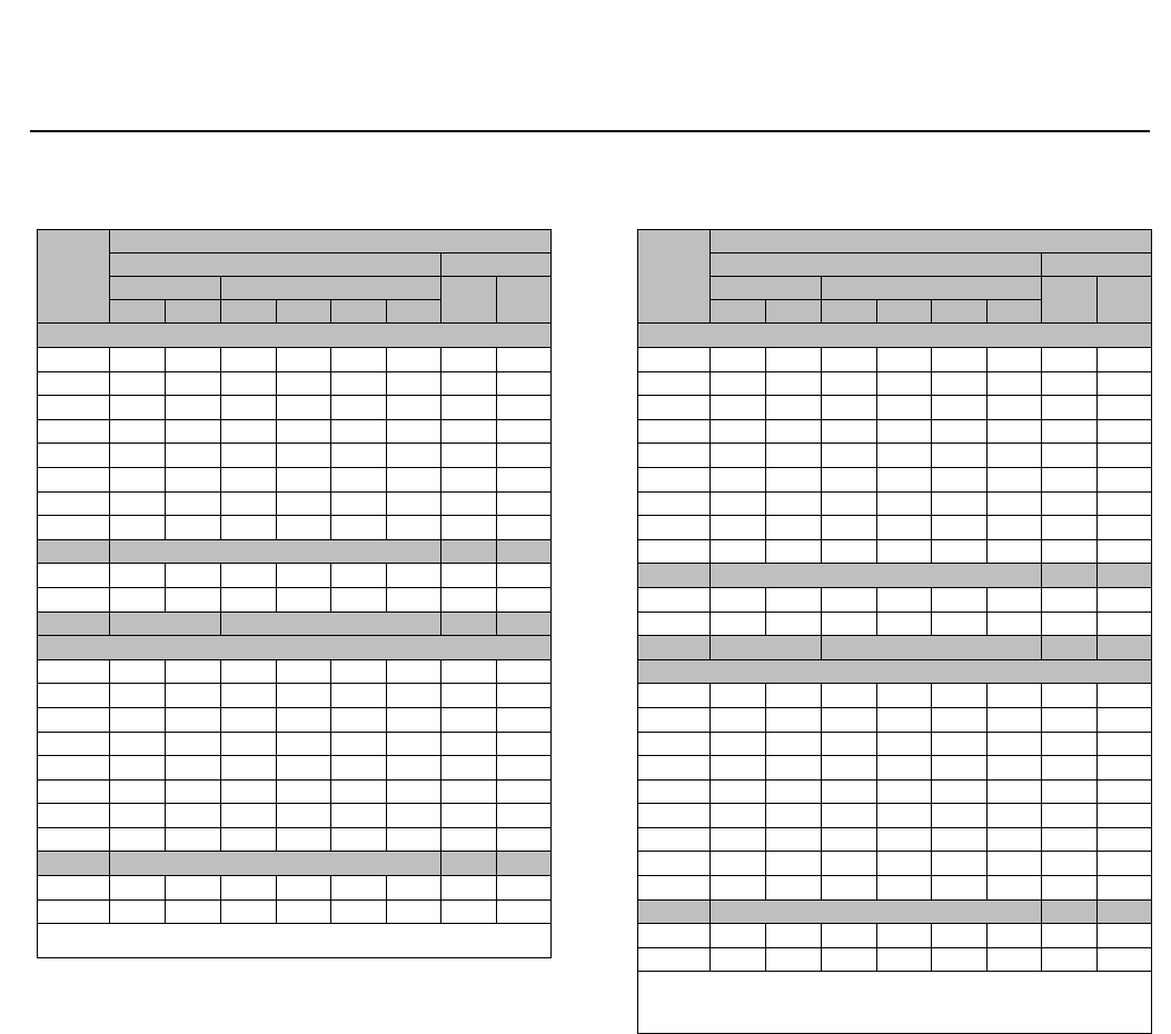
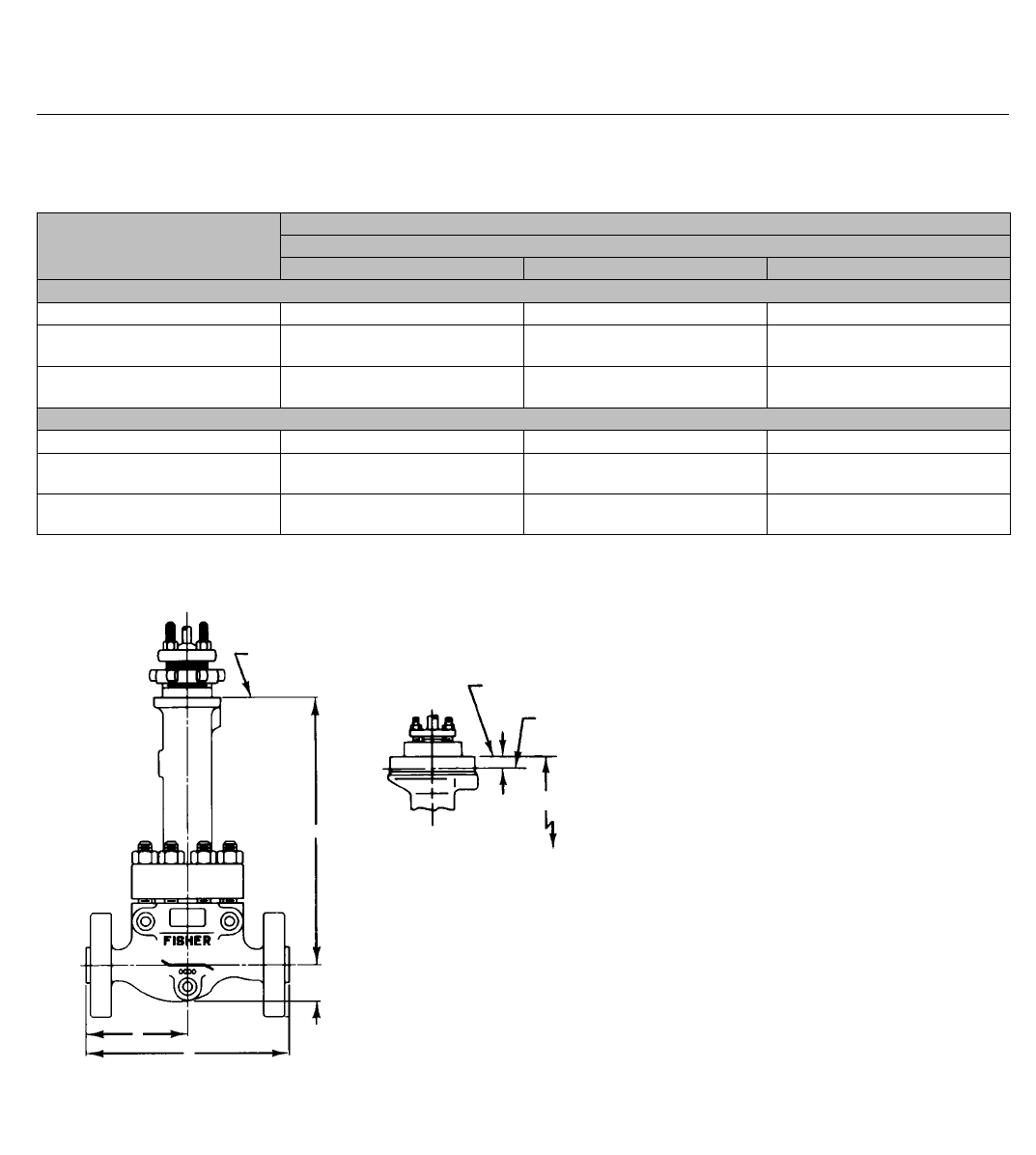
Table 14. Globe Valve Dimensions with Standard
Bonnet
VALVE
SIZE,
NPS
A(1)
ASME EN
CL900 CL1500 PN160 PN250
RF RTJ BWE SWE RF RTJ
mm
1292 292 292 292 292 292 269 277
2375 378 375 375 375 378 344 360
3442 445 460 --- 460 464 442 460
4x3 460 463 460 --- 479 482 --- ---
4511 514 530 --- 530 533 511 530
6x4 544 547 530 --- 598 604 --- ---
6714 718 768 --- 768 775 714 768
8x6 730 733 768 --- 787 797 --- ---
CL2500
1--- --- 318 318 318 318 --- ---
2--- --- 400 400 413 416 --- ---
CL900 CL1500 PN160 PN250
Inches
111.50 11.50 11.50 11.50 11.50 11.50 10.58 10.90
214.75 14.88 14.75 14.75 14.75 14.88 13.56 14.18
317.38 17.50 18.12 --- 18.12 18.25 17.38 18.12
4x3 18.12 18.25 18.12 --- 18.88 19.00 --- ---
420.12 20.25 20.88 --- 20.88 21.00 20.12 20.88
6x4 21.44 21.56 20.88 --- 23.56 23.81 --- ---
628.12 28.25 30.25 --- 30.25 30.50 28.12 30.25
8x6 28.75 28.88 30.25 --- 31.00 31.38 --- ---
CL2500
1--- --- 12.50 12.50 12.50 12.50 --- ---
2--- --- 15.75 15.75 16.25 16.38 --- ---
1. RF-raised-face flanges; RTJ-ring-type joint flanges; BWE-buttwelding ends;
SWE-socketweld ends.
Table 15. Globe Valve Dimensions with Standard
Bonnet
VALVE
SIZE,
NPS
B(1)
ASME EN
CL900 CL1500 PN160 PN250
RF RTJ BWE SWE RF RTJ
mm
1146 146 146 146 146 146 134 138
2187 189 187 187 187 189 172 180
3(2) 221 222 230 --- 230 232 --- ---
3(3) 200 202 210 --- 210 211 192 202
4x3 212 214 209 --- 222 223 --- ---
4229 230 238 --- 238 240 218 232
6x4 249 250 238 --- 276 279 --- ---
6310 311 337 --- 337 340 298 316
8x6 317 319 336 --- 345 350 --- ---
CL2500
1--- --- 159 159 159 159 --- ---
2--- --- 200 200 206 208 --- ---
CL900 CL1500 PN160 PN250
Inches
15.75 5.75 5.75 5.75 5.75 5.75 5.29 5.45
27.38 7.44 7.38 7.38 7.38 7.44 6.78 7.09
3(2) 8.69 8.75 9.06 --- 9.06 9.12 --- ---
3(3) 7.88 7.94 8.25 --- 8.25 8.31 7.54 7.94
4x3 8.38 8.44 8.25 --- 8.75 8.81 --- ---
49.00 9.06 9.38 --- 9.38 9.44 10.75 9.13
6x4 9.81 9.88 9.38 --- 10.88 11.00 --- ---
612.19 12.25 13.25 --- 13.25 13.38 11.72 12.43
8x6 12.5 12.56 13.25 --- 13.62 13.81 --- ---
CL2500
1--- --- 6.25 6.25 6.25 6.25 --- ---
2--- --- 7.88 7.88 8.12 8.19 --- ---
1. RF-raised-face flanges; RTJ-ring-type joint flanges; BWE-buttwelding ends;
SWE-socketweld ends.
2. Manufactured in U.S.A.
3. Manufactured in Europe and Japan.
HP Valve
D101635X012
Product Bulletin
51.2:HP
October 2014
24
Table 16. Globe Valve Dimensions with Standard
Bonnet
STANDARD BONNETS
VALVE
SIZE,
NPS
G
D
Yoke Boss Diameters, mm (Inches)
71 (2-13/16) 90 (3-9/16) 127
(5)
mm
CL900 and 1500
152 260 267 ---
2Std,
Whisper III,
Cavitrol III 3-Stage
77 261 267 331
2, Cavitrol III 2-Stage 77 279 286 344
4x3, 3(1) 121 322 311 370
3(2) 141 289 278 337
6x4, 4 175 --- 300 368
8x6, 6 248 --- 365 402
CL2500
163 35 35 ---
2Std,
Whisper III,
Cavitrol III 3-Stage
84 303 303 352
2, Cavitrol III 2-Stage 84 320 320 40
Inches
CL900 and 1500
12.06 10.25 10.50 ---
2Std,
Whisper III,
Cavitrol III 3-Stage
3.06 10.31 10.56 13.06
2, Cavitrol III 2-Stage 3.06 11.00 11.25 13.56
4x3, 3(1) 4.75 12.69 12.25 14.56
3(2) 5.56 11.38 10.94 13.25
6x4, 4 6.88 --- 11.81 14.50
8x6, 6 9.75 --- 14.38 15.81
CL2500
12.47 10.07 10.07 ---
2Std,
Whisper III,
Cavitrol III 3-Stage
3.31 11.91 11.91 13.85
2, Cavitrol III 2-Stage 3.31 12.59 12.59 14.53
1. Manufactured in U.S.A.
2. Manufactured in Europe and Japan.
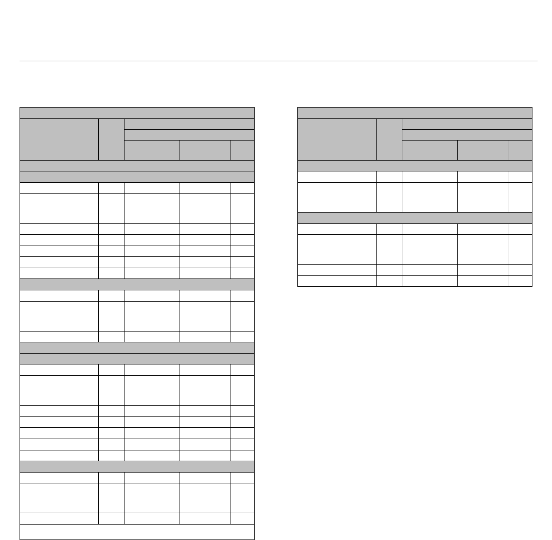
Table 17. Globe Valve Dimensions with Extension
Bonnet
EXTENSION BONNETS (CL900 AND 1500)
VALVE
SIZE,
NPS
G
D
Yoke Boss Diameters, mm (Inches)
71 (2-13/16) 90 (3-9/16) 127
(5)
mm
152 384 400 ---
2Std,
Whisper III,
Cavitrol III 3-Stage
77 430 446 505
Inches
12.06 15.12 15.75 ---
2Std,
Whisper III,
Cavitrol III 3-Stage
3.06 16.94 17.56 19.88
2, Cavitrol III 2-Stage 3.06 17.62 18.25 20.38
2, Cavitrol III 2-Stage 77 448 464 518
HP Valve
D101635X012
Product Bulletin
51.2:HP
October 2014
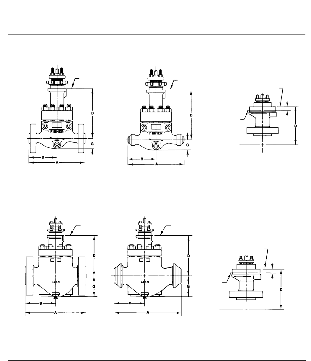
25
Figure 13. Globe Valve Dimensions with Standard Bonnet (also see tables 14, 15, and 16)
Note:
For dimensions of valves with other end connections, consult your Emerson Process Management sales office.
127mm (5-INCH) DIAMETER YOKE BOSS
FOR USE WITH FLANGED OR
BUTTWELDING VALVE
mm
(INCHES)
MATCH LINE FOR 585C SERIES
ACTUATORS AND TYPE 657,
667 SIZE 100 ACTUATORS
mm
(INCHES)
FLANGED VALVE WITH 71 OR 90 mm
(2-13/16 OR 3-9/16 INCH)
DIAMETER YOKE BOSS
BUTTWELDING END VALVE WITH 71 OR 90 mm
(2-13/16 OR 3-9/16 INCH)
DIAMETER YOKE BOSS
127mm (5-INCH) DIAMETER YOKE BOSS
FOR USE WITH ALL
VALVES
FLANGED VALVE WITH 71 OR 90 mm
(2-13/16 OR 3-9/16 INCH)
DIAMETER YOKE BOSS
BUTTWELDING END VALVE WITH 71 OR 90 mm
(2-13/16 OR 3-9/16 INCH)
DIAMETER YOKE BOSS
TYPICAL NPS 1, 2, AND 3
TYPICAL NPS 3 (EUROPE AND JAPAN MANUFACTURE), 4, AND 6
A5700A-3
A2719A-4
25.4
(1.00)
25.4
(1.00)
MATCH LINE FOR 585C SERIES
ACTUATORS AND TYPE 657,
667 SIZE 100 ACTUATORS
MATCH LINE FOR
ACTUATOR
MATCH LINE FOR
ACTUATOR
MATCH LINE FOR
ACTUATOR
MATCH LINE FOR
ACTUATOR
MATCH LINE FOR
ALL OTHER
ACTUATORS
MATCH LINE FOR
ALL OTHER
ACTUATORS
HP Valve
D101635X012
Product Bulletin
51.2:HP
October 2014
26
Table 18. Dimensions D for Style 1 Extension Bonnet
(A, B, and G Dimensions Listed in Figure 13 Do Not Change When Extension Bonnet is Used)
VALVE SIZE,
NPS
D
Yoke Boss Diameters, mm (Inches)
71 (2-13/16) 90 (3-9/16) 127 (5)
mm
1(stdtrim) 383 390 ---
2 (std, Whisper III,
Cavitrol III, 3-stage trim) 430 445 504
2(CavitrolIII
2-stage trim) 447 463 517
Inches
1(stdtrim) 15.09 15.34 ---
2 (std, Whisper III,
Cavitrol III 3-stage trim) 16.91 17.53 19.84
2(CavitrolIII
2-stage trim) 17.59 18.22 20.34
Figure 14. Dimensions D for Style 1 Extension Bonnet (A, B, and G Dimensions Listed in Figure 13 Do Not Change
When Extension Bonnet is Used) (also see tables 17 and 18)
MATCH LINE
FOR ACTUATOR MATCH LINE FOR
585C SERIES ACTUATORS
MATCH LINE FOR ALL
OTHER ACTUATORS
FLANGED VALVE WITH STYLE 1
EXTENSION BONNET HAVING 71 OR 90 mm
(2-13/16 OR 3-9/16 INCH)
DIAMETER YOKE BOSS
127 mm (5-INCH) DIAMETER YOKE BOSS
FOR STYLE 1 EXTENSION BONNET
mm
(INCHES)
25.4
(1.00)
D
D
G
B
A
A5701A-2

HP Valve
D101635X012
Product Bulletin
51.2:HP
October 2014
27
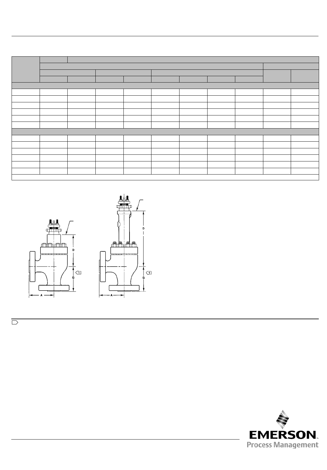
Table 19. Angle Valve Dimensions with Standard Bonnet
STANDARD BONNETS
VALVE
SIZE,
NPS
D
Yoke Boss Diameters, mm (Inches)
71 (2-13/16) 90 (3-9/16) 127 (5)
CL900 and 1500 CL2500 CL900 and 1500 CL2500 CL900 and 1500 CL2500
mm
1230 204 238 210 --- ---
2Std,
Whisper III,
Cavitrol III 3-Stage
227 240 233 229 297 288
2
Cavitrol III 2-Stage 244 257 251 246 314 305
3259 --- 265 --- 329 ---
4289 --- 278 --- 337 ---
6--- --- 300 --- 368 ---
8--- --- 364 --- 401 ---
Inches
19.06 8.04 9.38 8.28 --- ---
2Std,
Whisper III,
Cavitrol III 3-Stage
8.94 9.45 9.19 9.00 11.69 11.32
2
Cavitrol III 2-Stage 9.62 10.13 9.88 9.69 12.38 12.01
310.19 --- 10.44 --- 12.94 ---
411.38 --- 10.94 --- 13.25 ---
6--- --- 11.81 --- 14.50 ---
8--- --- 14.34 --- 15.77 ---
EXTENSION BONNETS
VALVE
SIZE,
NPS
D
Yoke Boss Diameters, mm (Inches)
71 (2-13/16) 90 (3-9/16) 127 (5)
CL900 and 1500 CL2500 CL900 and 1500 CL2500 CL900 and 1500 CL2500
mm
1354 373 371 388 --- ---
2Std,
Whisper III,
Cavitrol III 3-Stage
395 --- 411 --- 470 ---
2
Cavitrol III 2-Stage 413 --- 429 --- 487 ---
Inches
113.94 14.67 14.62 15.28 --- ---
2Std,
Whisper III,
Cavitrol III 3-Stage
15.56 --- 16.19 --- 18.50 ---
2
Cavitrol III 2-Stage 16.25 --- 16.88 --- 19.19 ---
HP Valve
D101635X012
Product Bulletin
51.2:HP
October 2014
28
Table 20. Angle Valve Dimensions with Standard Bonnet
VALVE
SIZE,
NPS
GA&G
(1)
ASME EN
CL2500 CL900 CL1500 PN160 PN250
SWE SWE RF RTJ BWE SWE RF RTJ
mm
1141 102 141 141 141 141 141 141 130 134
2184 124 178 179 178 178 178 179 163 170
3--- --- 226 227 235 --- 235 237 --- ---
4--- --- 273 275 273 --- 273 275 --- ---
6--- --- 325 327 353 --- 353 356 --- ---
8--- --- 387 389 416 --- 416 421 --- ---
Inches
15.56 4.00 5.56 5.56 5.56 5.56 5.56 5.56 5.10 5.26
27.25 4.88 7.00 7.06 7.00 7.00 7.00 7.06 6.40 6.71
3--- --- 8.88 8.94 9.25 --- 9.25 9.31 --- ---
4--- --- 10.75 10.81 10.75 --- 10.75 10.81 --- ---
6--- --- 12.81 12.88 13.88 --- 13.88 14.00 --- ---
8--- --- 15.25 15.31 16.38 --- 16.38 16.56 --- ---
1. RF–raised-face flanges; RTJ–ring-type-joint flanges; BWE–buttwelding ends; SWE–socket-weld ends.
Figure 15. Angle Valve Dimensions with Standard Bonnet (also see tables 19 and 20)
Note:
For dimensions of valves with other end connections, consult your Emerson Process Management sales office.
For CL900 and 1500 valves, G = A. For CL2500 valves, see table 20 for the G dimension.
1
MATCH LINE
FOR ACTUATOR
FLANGED VALVE WITH 71 OR 90
mm (2-13/16 OR 3-9/16 INCH)
DIAMETER YOKE BOSS
A6018A-1
MATCH LINE
FOR ACTUATOR
FLANGED VALVE WITH STYLE 1 EXTENSION BONNET
HAVING 71 OR 90 mm
(2-13/16 OR 3-9/16 INCH) DIAMETER YOKE BOSS
Emerson Process Management
Marshalltown, Iowa 50158 USA
Sorocaba, 18087 Brazil
Chatham, Kent ME4 4QZ UK
Dubai, United Arab Emirates
Singapore 128461 Singapore
www.Fisher.com
The contents of this publication are presented for informational purposes only, and while every effort has been made to ensure their accuracy, they arenot
to be construed as warranties or guarantees, express or implied, regarding the products or services described herein or their use or applicability. All sales are
governed by our terms and conditions, which are available upon request. We reserve the right to modify or improve the designs or specifications of such
products at any time without notice.
E1991, 2014 Fisher Controls International LLC. All rights reserved.
Fisher, FIELDVUE, WhisperFlo, Cavitrol, Whisper Trim, and ENVIRO-SEAL are marks owned by one of the companies in the Emerson Process Management
business unit of Emerson Electric Co. Emerson Process Management, Emerson, and the Emerson logo are trademarks and service marks of Emerson Electric
Co. All other marks are the property of their respective owners.
Neither Emerson, Emerson Process Management, nor any of their affiliated entities assumes responsibility for the selection, use or maintenance
of any product. Responsibility for proper selection, use, and maintenance of any product remains solely with the purchaser and end user.
