Emerson Liebert Ds Precision Cooling System 28 105Kw Technical Specifications
2015-03-30
: Emerson Emerson-Liebert-Ds-Precision-Cooling-System-28-105Kw-Technical-Specifications-680436 emerson-liebert-ds-precision-cooling-system-28-105kw-technical-specifications-680436 emerson pdf
Open the PDF directly: View PDF ![]() .
.
Page Count: 176 [warning: Documents this large are best viewed by clicking the View PDF Link!]
- Liebert DS Model Number
- 1.0 Cooling Configurations
- 2.0 Blower Configurations
- Figure 1 Blower configurations—Downflow, front and rear supply models, EC fans
- Figure 2 Blower configurations—Downflow, bottom supply and under-floor supply models, EC fans
- Figure 3 Blower configurations—Downflow, front and rear supply models, centrifugal fans
- Figure 4 Blower configurations—Upflow, front return models, centrifugal fans
- Figure 5 Blower configurations—Upflow, rear return models, centrifugal fans
- 3.0 Air-Cooled Systems
- 3.1 Capacity and Physical Data
- Table 1 Performance Data—Air-cooled, EC fan, under-floor discharge
- Table 2 Performance data—Air-cooled, centrifugal fan
- Table 3 Physical data—Air-cooled systems
- Table 4 Electrical data—Air-cooled systems with EC fans
- Table 5 Electrical data—Air-cooled systems with centrifugal fans
- Figure 6 Electrical field connections—Upflow and downflow models, single molded case switch disconnect with main fuses
- Figure 7 Electrical field connections—Upflow and downflow models, dual fused disconnect switches
- 3.2 Standard Electrical Connections
- 3.3 Optional Electrical Connections
- 3.4 Optional Low-Voltage Terminal Package Connections
- 3.5 Dimensions—Liebert DS 028-042, Downflow, Air-Cooled Models
- Figure 8 Dimensions—downflow, air-cooled, 28-42kW (8-12 ton), scroll or digital scroll compressors with centrifugal fans
- Table 6 Weights—downflow, air-cooled, 28-42kW (8-12 ton), scroll/digital scroll compressors
- Figure 9 Dimensions—downflow, air-cooled, 28-42kW (8-12 ton), front and/or rear discharge models
- Figure 10 Primary connection locations—downflow, air-cooled, 28-42kW (8-12 ton), scroll or digital scroll compressors with centrifugal fans
- Table 7 Piping data—downflow, air-cooled, 28-42kW (8-12 ton), scroll/digital scroll
- Figure 11 Disassembly dimensions—downflow, air-cooled, 28-42kW (8-12 ton), scroll or digital scroll compressors with centrifugal fans
- Table 8 Component weights—downflow, air-cooled, 28-42kW (8-12 ton), scroll or digital scroll compressors
- Figure 12 Dimensions—downflow, air-cooled, 28-42kW (8-12 ton), semi-hermetic compressors with centrifugal fans
- Table 9 Weights—downflow, air-cooled, 28-42kW (8-12 ton), semi-hermetic compressors
- Figure 13 Primary connection locations—downflow, air-cooled, 28-42kW (8-12 ton), semi-hermetic compressors with centrifugal fans
- Table 10 Piping data—downflow, air-cooled, 28-42kW (8-12 ton), semi-hermetic compressors
- Figure 14 Disassembly dimensions—downflow, air-cooled, 28-42kW (8-12 ton), semi-hermetic compressors with centrifugal fans
- Table 11 Component weights—downflow, air-cooled, 28-42kW (8-12 ton), semi-hermetic compressors
- 3.6 Dimensions—Liebert DS 053-077, Downflow, Air-Cooled Models
- Figure 15 Dimensions—downflow, air-cooled, 53-77kW (15-22 ton), scroll or digital scroll compressors with centrifugal fans
- Table 12 Weights—downflow, air-cooled, 53-77kW (15-22 ton), scroll or digital scroll compressors
- Figure 16 Primary connection locations—downflow, air-cooled, 53-77kW (15-22 ton), scroll or digital scroll compressors with centrifugal fans
- Table 13 Piping data—downflow, air-cooled, 53-77kW (15-22 ton), scroll or digital scroll compressors ***
- Figure 17 Dimensions—downflow, air-cooled, 53-77kW (15-22 ton), front and/or rear discharge models with EC fans
- Figure 18 Primary connection locations—downflow air-cooled 53-77kW (15-22 ton), scroll or digital scroll compressors with EC fans, front, rear or bottom discharge
- Table 14 Piping details—downflow air-cooled 53-77kW (15-22 ton) with EC fans, scroll or digital scroll compressors ***
- Figure 19 Disassembly dimensions—downflow, air-cooled, 53-77kW (15-22 ton), scroll or digital scroll compressors
- Table 15 Component weights—downflow, air-cooled, 53-77kW (15-22 ton), scroll or digital scroll compressors *
- Figure 20 Dimensions—downflow, air-cooled, 53-77kW (15-22 ton) with centrifugal fans, semi-hermetic compressors with centrifugal fans
- Table 16 Weights—downflow, air-cooled, 53-77kW (15-22 ton), semi-hermetic compressors
- Figure 21 Primary connection locations—downflow, air-cooled, 53-77kW (15-22 ton), semi-hermetic compressors with centrifugal fans
- Table 17 Piping data—downflow, air-cooled, 53-77kW (15-22 ton), semi-hermetic compressors
- Figure 22 Primary connection locations—downflow, air-cooled 53-77kW (15-22 ton), semi-hermetic compressors with EC fans, front, rear or bottom discharge
- Table 18 Piping details—downflow, air-cooled 53-77kW (15-22 ton) with EC fans, semi-hermetic compressors
- Figure 23 Disassembly dimensions—downflow, air-cooled, 53-77kW (15-22 ton), semi-hermetic compressors with centrifugal fans
- Table 19 Component weights—downflow, air-cooled, 53-77kW (15-22 ton), semi-hermetic compressors
- 3.7 Dimensions—Liebert DS 105, Downflow, Air-Cooled Models
- Figure 24 Dimensions—downflow, air-cooled, 105kW (30 ton), standard scroll and semi-hermetic compressors with centrifugal fans
- Table 20 Weights—downflow, air-cooled, 105kW (30 ton), standard scroll and semi-hermetic compressors
- Figure 25 Primary connection locations—downflow, air-cooled, 105kW (30 ton), standard scroll and semi-hermetic compressors with centrifugal fans
- Table 21 Piping data—downflow, air-cooled, 105kW (30 ton), standard scroll*** and semi-hermetic compressors
- Figure 26 Dimensions—downflow, air-cooled, 105kW (30 ton), front discharge models with EC fans
- Figure 27 Primary connection locations—downflow, air-cooled 105kW (30 ton), standard scroll and semi-hermetic compressors with EC fans, front, rear or bottom discharge
- Table 22 Piping data—downflow, air-cooled 105kW (30 ton) with EC fans, standard scroll*** and semi-hermetic compressors
- Figure 28 Disassembly dimensions—downflow, air-cooled, 105kW (30 ton), standard scroll compressors with centrifugal
- Table 23 Component weights—downflow, air-cooled, 105kW (30 ton), standard scroll compressors *
- Figure 29 Disassembly dimensions—downflow, air-cooled, 105kW (30 ton), semi-hermetic compressors with centrifugal
- Table 24 Component weights—downflow, air-cooled, 105kW (30 ton), semi-hermetic compressors
- 3.8 Dimensions—Liebert DS 028-042, Upflow, Air-Cooled Models
- Figure 30 Dimensions—upflow, air-cooled, 28-42kW (8-12 ton), scroll or digital scroll compressors with centrifugal fans
- Table 25 Weights—upflow, air-cooled, 28-42kW (8-12 ton), scroll or digital scroll compressors
- Figure 31 Primary connection locations—upflow, air-cooled, 28-42kW (8-12 ton), scroll or digital scroll compressors with centrifugal fans
- Table 26 Piping data—upflow, air-cooled, 28-42kW (8-12 ton), scroll or digital scroll compressors
- Figure 32 Disassembly dimensions—upflow, air-cooled, 28-42kW (8-12 ton), scroll or digital scroll compressors with centrifugal fans
- Table 27 Component weights—upflow, air-cooled, 28-42kW (8-12 ton), scroll or digital scroll compressors
- Figure 33 Dimensions—upflow, air-cooled, 28-42kW (8-12 ton), semi-hermetic compressors with centrifugal fans
- Table 28 Weights—upflow, air-cooled, 28-42kW (8-12 ton), semi-hermetic compressors
- Figure 34 Primary connection locations—upflow, air-cooled, 28-42kW (8-12 ton), semi-hermetic compressors with centrifugal fans
- Table 29 Piping data—upflow, air-cooled, 28-42kW (8-12 ton), semi-hermetic compressors
- Figure 35 Disassembly dimensions—upflow, air-cooled, 28-42kW (8-12 ton), semi-hermetic compressors with centrifugal fans
- Table 30 Component weights—upflow, air-cooled, 28-42kW (8-12 ton), semi-hermetic compressors
- Figure 36 Blower outlet and deck dimensions—upflow, air-cooled, 28-42kW (8-12 ton) with centrifugal fans
- Table 31 Blower outlet and deck dimensions—upflow, air-cooled, 28-42kW (8-12 ton)
- 3.9 Dimensions—Liebert DS 053-077, Upflow, Air-Cooled Models
- Figure 37 Dimensions—upflow, air-cooled, 53-77kw (15-22 ton), scroll or digital scroll compressors with centrifugal fans
- Table 32 Weights - upflow, air-cooled, 53-77kw (15-22 ton)—scroll or digital scroll compressors
- Figure 38 Primary connection locations—upflow, air-cooled, 53-77kw (15-22 ton), scroll compressors with centrifugal fans
- Table 33 Piping data - upflow, air-cooled, 53-77kw (15-22 ton)—scroll compressors ***
- Figure 39 Disassembly dimensions—upflow, air-cooled, 53-77kw (15-22 ton), scroll or digital scroll compressors with centrifugal fans
- Table 34 Component weights—upflow, air-cooled, 53-77kw (15-22 ton), scroll or digital scroll compressors
- Figure 40 Dimensions—upflow, air-cooled 53-77kw (15-22 ton), semi-hermetic compressors with centrifugal fans
- Table 35 Weights—upflow, air-cooled, 53-77kW (15-22 ton), semi-hermetic compressors
- Figure 41 Primary connection locations—upflow air-cooled 53-77kW (15-22 ton), semi-hermetic compressors with centrifugal fans
- Table 36 Piping data—upflow, air-cooled, 53-77kW (15-22 ton), semi-hermetic compressors
- Figure 42 Disassembly dimensions—upflow, air-cooled, 53-77kW (15-22 ton), semi-hermetic compressors with centrifugal fans
- Table 37 Component weights—upflow air-cooled 53-77kw (15-22 ton), semi-hermetic compressors
- Figure 43 Blower outlet and deck dimensions—upflow 53-77kW (15-22 ton) with centrifugal fans
- Table 38 Blower outlet and deck dimension—upflow, 53-77kW (15-22 ton)
- 3.10 Dimensions—Liebert DS 105, Upflow, Air-Cooled Models
- Figure 44 Dimensions—upflow, air-cooled, 105kW (30 ton), semi-hermetic and scroll compressors with centrifugal fans
- Table 39 Weights—upflow, air-cooled, 105kW (30 ton), semi-hermetic and scroll compressors *
- Figure 45 Primary connection locations—upflow, air-cooled, 105kW (30 ton), semi-hermetic and scroll compressors with centrifugal fans
- Table 40 Piping data—upflow, air-cooled 105kW (30 ton), semi-hermetic and scroll compressors ***
- Figure 46 Disassembly dimensions—upflow, air-cooled, 105kW (30 ton), standard scroll compressors with centrifugal fans
- Table 41 Component weights—upflow, air-cooled, 105kW (30 ton), standard scroll compressors *
- Figure 47 Disassembly dimensions—upflow, air-cooled, 105kW (30 ton), semi-hermetic compressors with centrifugal fans
- Table 42 Component weights—upflow, air-cooled, 105kW (30 ton), semi-hermetic compressors
- Figure 48 Blower outlet and deck dimensions—upflow 105kW (30 ton), with centrifugal fans
- Table 43 Blower outlet and deck dimension—upflow 105kW (30 ton), with centrifugal fans
- 3.11 Heat Rejection—Liebert MC, Fin/Tube and Piggyback Condensers
- 3.11.1 Liebert MC Microchannel Condensers
- Liebert MC Condenser Selection
- Table 44 Traditional open room (75°F/45RH return air conditions)
- Table 45 High-temperature return (85°F/33RH return air conditions)
- Table 46 Traditional open room (75°F/45RH return air conditions) Liebert QuietLine™ sound levels
- Dimensions—Liebert MC™ Condensers
- Figure 49 Condenser planning dimensions—MCM080, MCM160 with/without Liebert Lee-Temp™
- Figure 50 Cabinet and anchor dimensions—Liebert MC™ models MCL110 and MCL220 with Liebert Lee- Temp receivers
- Figure 51 Condenser planning dimensions—MCL110 and MCL220
- Figure 52 Typical Liebert MC™ condenser footprint—dimensions
- Electrical Data—Liebert MC™ Condensers
- Table 47 Liebert MC electrical data, three-phase, 60Hz condenser, Premium Version (EC control)
- Electrical Field Connections—Liebert MC Condensers
- Figure 53 Electrical field connections—Liebert MC Condensers premium efficiency control, with and without Liebert Lee-Temp
- Electrical Connections—Premium Efficiency Control, Liebert MC Condensers
- NOTES
- 3.11.1 Liebert MC Microchannel Condensers
- 3.12 Piping—Liebert MC™ Condensers
- Typical System Configurations—Liebert MC Condensers
- Figure 54 Liebert MC piping schematic with and without Liebert Lee-Temp
- Figure 55 Piping dimensions—Liebert MC™ dual circuit condensers with Liebert Lee-Temp™
- Table 48 Piping dimensions—Liebert MC dual circuit condensers with Liebert Lee-Temp
- Figure 56 Piping connections—Liebert MC™ dual circuit two-fan and four-fan units
- 3.12.1 Fin/Tube Condensers
- Fin/Tube Selections
- Table 49 Liebert DS air-cooled condenser selection, finned-tubular design, R-407C
- Dimensions—Fin/Tube Condensers
- Table 50 Fin/tube condenser physical data and R-407C refrigerant required per condenser circuit
- Figure 57 Fin/tube condenser dimensions, 2-fan model
- Figure 58 Fin/tube condenser dimensions, 3-fan and 4-fan models
- Figure 59 Fin/tube condenser dimensions, 6-fan and 8-fan models
- Electrical Data—Fin/Tube Condensers
- Table 51 Fin/tube condenser data, 60Hz
- Table 52 Fin/tube condenser data, Liebert Quiet-Line™ (Liebert Lee-Temp™ controlled/fan-cycling), 60Hz
- Electrical Field Connections—Liebert Fin/Tube Condensers
- Figure 60 Electrical field connections for Fan Speed Control fin/tube condensers
- Figure 61 Electrical field connections for VFD control fin/tube condensers
- Figure 62 Electrical field connections for Liebert Lee-Temp control fin/tube condensers
- Table 53 Liebert Lee-Temp receiver electrical data, fin/tube condensers
- Piping—Fin/Tube Condensers
- Typical System Configurations—Fin/Tube
- Figure 63 Piping schematic, air-cooled with semi-hermetic compressor with fin/tube condenser
- Figure 64 Piping schematic, air-cooled with scroll or digital scroll compressor with fin/tube condenser
- Figure 65 VFD and Fan Speed Control condenser piping—Fin/tube condensers
- Figure 66 Liebert Lee-Temp head pressure control condenser piping—Fin/tube condensers
- 3.12.2 Piggyback Condensers
- Piggyback Selections
- Table 54 Liebert DS piggyback condenser selection
- Table 55 Piggyback condenser airflow and static pressure data
- Dimensions—Indoor Piggyback Condensers
- Figure 67 Piggyback condenser planning dimensions
- Table 56 Piggyback condenser dimensions, in. (mm)
- Table 57 Piggyback condenser physical data, 60Hz
- Electrical Data—Piggyback Condensers
- Table 58 Piggyback condenser electrical data, 60 Hz, 3 phase 1
- Electrical Field Connections—Liebert Piggyback Condensers
- Figure 68 Electrical field connections for Liebert piggyback condensers
- Table 59 Separate electrical supply requirements for Liebert Lee-Temp™ receivers, 60Hz, 1 Ph
- Figure 69 Electrical field connections for Liebert piggyback condensers
- Figure 70 Piggyback condenser piping and electrical connection locations
- Table 60 Dimensions—Piggyback condensers, in. (mm)
- Table 61 Piping connection sizes, ODS, in. (mm)
- Figure 71 Piping schematic—Liebert DS with piggyback condenser and Liebert Lee-Temp™
- 3.13 Ancillary Items—Air-Cooled Systems
- Figure 72 Floor stand dimensions—28-42kW (8-12 ton), downflow
- Table 62 Floor stand and floor planning dimensions—28-42kW (8-12 ton), downflow
- Figure 73 Floor stand dimensions—53-77kW (15-22 ton), downflow
- Table 63 Floor stand and floor planning dimensions—53-77kW (15-22 ton), downflow
- Figure 74 Floor stand and floor planning dimension, downflow 53-77kW (15-22 tons) models with EC fans
- Table 64 Floor stand and floor planning dimensions—53-77kW (15-22 ton), downflow with EC fans
- Figure 75 Floor stand and floor planning dimensions—downflow 105kW (30 ton) models with EC fans, standard scroll and semi-hermetic compressors without turning vane
- Figure 76 Floor stand dimensions—105kW (30 ton), downflow with turning vane and centrifugal fans
- Table 65 Floor stand and floor planning dimensions—105kW (30 ton), downflow
- Figure 77 Plenum dimensions—28-105kW (8-30 ton), upflow
- Table 66 Plenum dimensions, in. (mm)—28-105kW (8-30 ton), upflow
- Figure 78 Floor stand dimensions, piggyback condensers with centrifugal fans
- Table 67 Floor stand dimensions, in. (mm)
- Table 68 Floor stand height selection, in. (mm)
- 3.1 Capacity and Physical Data
- 4.0 Water-Cooled, Glycol-Cooled and GLYCOOL Systems
- 4.1 Capacity and Physical Data
- Table 69 Performance data—Water-cooled, EC fans
- Table 70 Performance data—Water-cooled units with centrifugal fans
- Table 71 Physical data—Water-cooled units
- Table 72 Performance data—Glycol-cooled units with EC fans
- Table 73 Performance Data—Glycol-cooled units with centrifugal fans
- Table 74 Physical data—Glycol-cooled units
- Table 75 Performance data—GLYCOOL units with EC fans
- Table 76 Performance data—GLYCOOL units with centrifugal fans
- Table 77 Physical data—GLYCOOL units
- Table 78 Electrical data—Water/glycol-cooled systems with EC fans
- Table 79 Electrical data—Water/glycol-cooled systems with centrifugal fans
- Figure 79 Electrical field connections—Upflow and downflow models, single molded case switch disconnect with main fuses
- Figure 80 Electrical field connections—Upflow and downflow models, dual fused disconnect switches
- 4.2 Standard Electrical Connections
- 4.3 Optional Electrical Connections
- 4.4 Optional Low-Voltage Terminal Package Connections
- 4.5 Dimensions—Liebert DS 028-042, Downflow, Water/Glycol/GLYCOOL Models
- Figure 81 Dimensions—water/glycol/GLYCOOL, 28-42kW (8-12 ton), downflow, all compressors with centrifugal fans
- Table 80 Weights—Water/glycol/GLYCOOL, 28-42kW (8-12 ton), downflow, all compressors
- Figure 82 Primary connection locations—Water/glycol/GLYCOOL, 28-42kW (8-12 ton), downflow, all compressors with centrifugal fans
- Table 81 Piping data—Water/glycol/GLYCOOL, 28-42kW (8-12 ton), downflow, all compressors
- Figure 83 Dimensions—downflow, water/glycol/GLYCOOL systems, 28-42kW (8-12 ton), with EC fans, front and/or rear discharge models
- Figure 84 Disassembly dimensions—Water/glycol/GLYCOOL, 28-42kW (8-12 ton), downflow, all compressors with centrifugal fans
- Table 82 Component weights—Water/glycol/GLYCOOL, 28-42kW (8-12 ton), downflow, all compressors
- 4.6 Dimensions—Liebert DS 053-077, Downflow, Water/Glycol/GLYCOOL Models
- Figure 85 Dimensions—Water/glycol/GLYCOOL, 53-77kW (15-22 ton), downflow, all compressors with centrifugal fans
- Table 83 Weights—Water/glycol/GLYCOOL, 53-77kW (15-22 ton), downflow, all compressors
- Figure 86 Dimensions—downflow, water/glycol, GLYCOOL systems, 53-77kW (15-22 ton), front and/or rear discharge models
- Figure 87 Primary connection locations—Water/glycol/GLYCOOL, 53-77kW (15-22 ton), all compressor models with EC fans
- Table 84 Piping data—Water/glycol/GLYCOOL, 53-77kW (15-22 ton), downflow with EC fans
- Figure 88 Primary connection locations—Water/glycol/GLYCOOL, 53-77kW (15-22 ton), downflow, all compressor models with centrifugal fans
- Table 85 Piping data—Water/glycol/GLYCOOL, 53-77kW (15-22 ton), downflow
- Figure 89 Disassembly dimensions—Water/glycol/GLYCOOL, 53-77kW (15-22 ton), downflow, all compressors with centrifugal or EC fans
- Table 86 Component weights—Water/glycol/GLYCOOL, 53-77kW (15-22 ton), downflow, all compressors * with centrifugal or EC fans
- 4.7 Dimensions—Liebert DS 105, Downflow, Water/Glycol/GLYCOOL-Cooled Models
- Figure 90 Dimensions—Water/glycol/GLYCOOL 105kW (30 ton), downflow, semi-hermetic or scroll compressors with centrifugal or EC fans
- Table 87 Weights—Water/glycol/GLYCOOL 105kW (30 ton), downflow, semi-hermetic and scroll compressors *
- Figure 91 Dimensions—downflow, water/glycol,GLYCOOL systems, 105kW (30 ton), front discharge models with EC fans
- Figure 92 Primary connection locations—Water/glycol/GLYCOOL 105kW (30 ton), downflow, semi-hermetic or standard scroll compressors with EC fans
- Table 88 Piping data—Water/glycol/GLYCOOL 105kW (30 ton), downflow with EC fans, semi-hermetic and standard scroll compressors ***
- Figure 93 Primary connection locations—Water/glycol/GLYCOOL 105kW (30 ton), downflow, semi-hermetic or standard scroll compressors with centrifugal fans
- Table 89 Piping data—Water/glycol/GLYCOOL 105kW (30 ton), downflow, semi-hermetic and standard scroll compressors ***
- Figure 94 Disassembly dimensions—Water/glycol/GLYCOOL 105kW (30 ton), downflow, semi-hermetic or standard scroll compressors with centrifugal and EC fans
- Table 90 Component weights—Water/glycol/GLYCOOL 105kW (30 ton), downflow, semi-hermetic and standard scroll compressors
- 4.8 Dimensions—Liebert DS 028-042, Upflow, Water/Glycol/GLYCOOL-Cooled Models
- Figure 95 Dimensions—Water/glycol/GLYCOOL, 28-42kW (8-12 ton), upflow, all compressors with centrifugal fans
- Table 91 Weights—Water/glycol/GLYCOOL, 28-42kW (8-12 ton), upflow, all compressors
- Figure 96 Primary connection locations—Water/glycol/GLYCOOL, 28-42kW (8-12 ton), upflow, all compressors with centrifugal fans
- Table 92 Piping data—Water/glycol/GLYCOOL, 28-42kW (8-12 ton), upflow, all compressors
- Figure 97 Disassembly dimensions—Water/glycol/GLYCOOL, 28-42kW (8-12 ton), upflow, all compressors with centrifugal fans
- Table 93 Component weights—Water/glycol/GLYCOOL, 28-42kW (8-12 ton), upflow, all compressors
- Figure 98 Blower outlet location—28-42kW (8-12 ton), upflow with centrifugal fans
- Table 94 Blower outlet and deck dimensions—28-42kW (8-12 ton), upflow
- 4.9 Dimensions—Liebert DS 053-077, Upflow, Water/Glycol/GLYCOOL-Cooled Models
- Figure 99 Dimensions—Water/glycol/GLYCOOL, 53-77kw (15-22 ton), upflow, all compressors with centrifugal fans
- Table 95 Weights—Water/glycol/GLYCOOL, 53-77kw (15-22 ton), upflow, all compressors
- Figure 100 Primary connection locations—Water/glycol/GLYCOOL, 53-77kw (15-22 ton), upflow with centrifugal fans
- Table 96 Piping data—Water/glycol/GLYCOOL, 53-77kw (15-22 ton), upflow
- Figure 101 Disassembly dimensional data—Water/glycol/GLYCOOL, 53-77kw (15-22 ton), upflow, all compressors with centrifugal fans
- Table 97 Component weights—Water/glycol/GLYCOOL, 53-77kw (15-22 ton), upflow, all compressors
- Figure 102 Blower outlet and deck dimensions—53-77kW (15-22 ton), upflow, with centrifugal fans
- Table 98 Blower outlet and deck dimensions—53-77kW (15-22 ton), upflow, forward-curved fans
- 4.10 Dimensions—Liebert DS 105, Upflow, Water/Glycol/GLYCOOL Models
- Figure 103 Dimensions—Water/glycol/GLYCOOL,105kW (30 ton), upflow, semi-hermetic and standard scroll compressors with centrifugal fans
- Table 99 Weights—Water/glycol/GLYCOOL,105kW (30 ton), upflow, semi-hermetic and standard scroll compressors *
- Figure 104 Primary connection locations—Water/glycol/GLYCOOL,105kW (30 ton), upflow with centrifugal fans
- Table 100 Piping data—Water/glycol/GLYCOOL,105kW (30 ton), upflow
- Figure 105 Disassembly dimensions—Water/glycol/GLYCOOL,105kW (30 ton), upflow, all compressors with centrifugal fans
- Table 101 Component weights—Water/glycol/GLYCOOL,105kW (30 ton), upflow, all compressors
- Figure 106 Blower outlet and deck dimensions—105kW (30 ton), upflow with centrifugal fans
- Table 102 Blower outlet and deck dimensions—105kW (30 ton), upflow, forward-curved fans
- 4.11 Heat Rejection—Drycoolers and Pumps
- 4.11.1 Drycooler Selection—Prop Fan Drycoolers
- 4.11.2 Dimensions—Prop Fan Drycoolers
- 4.11.3 Electrical Data—Prop Fan Drycoolers
- 4.11.4 Piping—Prop Fan Drycoolers
- Figure 110 Typical piping arrangement, multiple prop fan drycoolers and multiple indoor units
- Table 109 Standard drycooler piping connection sizes and internal volume
- Table 110 Liebert Quiet-Line drycooler piping connection sizes and internal volume
- Figure 111 Piping schematic—Water/glycol semi-hermetic compressor models
- Figure 112 Piping schematic—Water/glycol scroll compressor models
- 4.11.5 Pump Packages & Expansion Tank
- Figure 113 Single pump package piping connections and dimension
- Table 111 Mounting hole dimensions, in. (mm)
- Figure 114 Dual pump package piping connections and dimensions
- Figure 115 Pump package expansion tank
- Expansion Tank (P/N 1C16717P1)
- Table 112 Glycol pump data
- Figure 116 Pump curve, 60 Hz
- Table 113 60Hz electrical values—Quiet-Line drycoolers with integral pump controls
- 4.11.6 Drycooler Selection—Indoor Piggyback Drycoolers
- 4.11.7 Weights and Dimensions—Indoor Piggyback Drycoolers
- 4.11.8 Electrical Data—Piggyback Drycoolers
- 4.11.9 System Piping—Piggyback Drycoolers
- 4.12 Ancillary Items—Water-Cooled Systems
- Figure 121 Floor stand dimensions—28-42kW (8-12 ton), downflow
- Table 120 Floor stand and floor planning dimensions—28-42kW (8-12 ton), downflow
- Figure 122 Floor stand dimensions—53-77kW (15-22 ton), downflow
- Table 121 Floor stand and floor planning dimensions—53-77kW (15-22 ton), downflow
- Figure 123 Floor stand dimensions—105kW (30 ton), downflow
- Table 122 Floor stand and floor planning dimensions—105kW (30 ton), downflow
- Figure 124 Floor stand dimensions, piggyback drycoolers with centrifugal fans
- Table 123 Floor stand dimensions, in. (mm)
- Table 124 Floor stand height selection, in. (mm)
- Figure 125 Plenum dimension—28-105kW (8-30 ton), upflow
- Table 125 Plenum dimensions, in. (mm)—28-105kW (8-30 ton), upflow
- 4.1 Capacity and Physical Data
- 5.0 Guide Specifications
- 1.0 GENERAL
- 2.0 PRODUCT
- 2.1 FRAME
- 2.2 FILTERS—DOWNFLOW UNIT
- 2.3 FAN SECTION
- 2.4 HUMIDIFIER
- 2.5 REHEAT
- 2.6 DUAL REFRIGERATION SYSTEM
- 2.7 LIEBERT iCOM™ MICROPROCESSOR CONTROL WITH SMALL GRAPHIC DISPLAY
- 2.8 DUAL-COOLING CHILLED WATER COIL
- 2.9 MISCELLANEOUS OPTIONS
- 2.9.1 Non-Locking Disconnect Switch (Optional)
- 2.9.2 High-Temperature Sensor (Optional)
- 2.9.3 Smoke Sensor (Optional)
- 2.9.4 Condensate Pump, Dual Float (Optional)
- 2.9.5 Low-Voltage Terminal Package (Optional)
- 2.9.6 Remote Humidifier Contact (Optional)
- 2.9.7 Main Fan Overload (Optional)
- 2.9.8 Compressor Overload (Optional)
- 2.10 AIR-COOLED SYSTEMS
- 2.11 Drycooler Glycol Fluid Cooler
- 2.12 LIEBERT LIQUI-TECT® SENSORS
- 2.13 FLOOR STAND
- 3.0 EXECUTION
Liebert® DS™ Thermal Management Unit
System Design Manual - 28-105kW (8-30 Tons), Downflow/Upflow, 60Hz
Floor Mounted, Air-Cooled, Water/Glycol-Cooled, GLYCOOL Economizer Coil, Dual-Cool DX with
Secondary Chilled Water Coil

i
TABLE OF CONTENTS
LIEBERT DS MODEL NUMBER . . . . . . . . . . . . . . . . . . . . . . . . . . . . . . . . . . . . . . . . . . . . . . . . . . . .1
1.0 COOLING CONFIGURATIONS . . . . . . . . . . . . . . . . . . . . . . . . . . . . . . . . . . . . . . . . . . . . . . . .2
2.0 BLOWER CONFIGURATIONS . . . . . . . . . . . . . . . . . . . . . . . . . . . . . . . . . . . . . . . . . . . . . . . .3
3.0 AIR-COOLED SYSTEMS. . . . . . . . . . . . . . . . . . . . . . . . . . . . . . . . . . . . . . . . . . . . . . . . . . . .6
3.1 Capacity and Physical Data. . . . . . . . . . . . . . . . . . . . . . . . . . . . . . . . . . . . . . . . . . . . . . . . . . . . 6
3.2 Standard Electrical Connections . . . . . . . . . . . . . . . . . . . . . . . . . . . . . . . . . . . . . . . . . . . . . . . 14
3.3 Optional Electrical Connections . . . . . . . . . . . . . . . . . . . . . . . . . . . . . . . . . . . . . . . . . . . . . . . 15
3.4 Optional Low-Voltage Terminal Package Connections . . . . . . . . . . . . . . . . . . . . . . . . . . . . . 15
3.5 Dimensions—Liebert DS 028-042, Downflow, Air-Cooled Models . . . . . . . . . . . . . . . . . . . . 16
3.6 Dimensions—Liebert DS 053-077, Downflow, Air-Cooled Models . . . . . . . . . . . . . . . . . . . . 23
3.7 Dimensions—Liebert DS 105, Downflow, Air-Cooled Models . . . . . . . . . . . . . . . . . . . . . . . . 32
3.8 Dimensions—Liebert DS 028-042, Upflow, Air-Cooled Models. . . . . . . . . . . . . . . . . . . . . . . 38
3.9 Dimensions—Liebert DS 053-077, Upflow, Air-Cooled Models. . . . . . . . . . . . . . . . . . . . . . . 45
3.10 Dimensions—Liebert DS 105, Upflow, Air-Cooled Models . . . . . . . . . . . . . . . . . . . . . . . . . . 52
3.11 Heat Rejection—Liebert MC, Fin/Tube and Piggyback Condensers. . . . . . . . . . . . . . . . . . . 57
3.11.1 Liebert MC Microchannel Condensers . . . . . . . . . . . . . . . . . . . . . . . . . . . . . . . . . . . . . . . . . . . 57
3.12 Piping—Liebert MC™ Condensers . . . . . . . . . . . . . . . . . . . . . . . . . . . . . . . . . . . . . . . . . . . . . 65
3.12.1 Fin/Tube Condensers . . . . . . . . . . . . . . . . . . . . . . . . . . . . . . . . . . . . . . . . . . . . . . . . . . . . . . . . . 68
3.12.2 Piggyback Condensers . . . . . . . . . . . . . . . . . . . . . . . . . . . . . . . . . . . . . . . . . . . . . . . . . . . . . . . . 78
3.13 Ancillary Items—Air-Cooled Systems . . . . . . . . . . . . . . . . . . . . . . . . . . . . . . . . . . . . . . . . . . . 84
4.0 WATER-COOLED, GLYCOL-COOLED AND GLYCOOL SYSTEMS . . . . . . . . . . . . . . . . . . . . .91
4.1 Capacity and Physical Data. . . . . . . . . . . . . . . . . . . . . . . . . . . . . . . . . . . . . . . . . . . . . . . . . . . 91
4.2 Standard Electrical Connections . . . . . . . . . . . . . . . . . . . . . . . . . . . . . . . . . . . . . . . . . . . . . . 105
4.3 Optional Electrical Connections . . . . . . . . . . . . . . . . . . . . . . . . . . . . . . . . . . . . . . . . . . . . . . 106
4.4 Optional Low-Voltage Terminal Package Connections . . . . . . . . . . . . . . . . . . . . . . . . . . . . 106
4.5 Dimensions—Liebert DS 028-042, Downflow, Water/Glycol/GLYCOOL Models . . . . . . . . 107
4.6 Dimensions—Liebert DS 053-077, Downflow, Water/Glycol/GLYCOOL Models . . . . . . . . 111
4.7 Dimensions—Liebert DS 105, Downflow, Water/Glycol/GLYCOOL-Cooled Models . . . . . 116
4.8 Dimensions—Liebert DS 028-042, Upflow, Water/Glycol/GLYCOOL-Cooled Models . . . . 121
4.9 Dimensions—Liebert DS 053-077, Upflow, Water/Glycol/GLYCOOL-Cooled Models . . . . 125
4.10 Dimensions—Liebert DS 105, Upflow, Water/Glycol/GLYCOOL Models. . . . . . . . . . . . . . 129
4.11 Heat Rejection—Drycoolers and Pumps . . . . . . . . . . . . . . . . . . . . . . . . . . . . . . . . . . . . . . . . 133
4.11.1 Drycooler Selection—Prop Fan Drycoolers . . . . . . . . . . . . . . . . . . . . . . . . . . . . . . . . . . . . . . . 133
4.11.2 Dimensions—Prop Fan Drycoolers . . . . . . . . . . . . . . . . . . . . . . . . . . . . . . . . . . . . . . . . . . . . . 133
4.11.3 Electrical Data—Prop Fan Drycoolers . . . . . . . . . . . . . . . . . . . . . . . . . . . . . . . . . . . . . . . . . . 136
4.11.4 Piping—Prop Fan Drycoolers. . . . . . . . . . . . . . . . . . . . . . . . . . . . . . . . . . . . . . . . . . . . . . . . . . 138
4.11.5 Pump Packages & Expansion Tank. . . . . . . . . . . . . . . . . . . . . . . . . . . . . . . . . . . . . . . . . . . . . 143
4.11.6 Drycooler Selection—Indoor Piggyback Drycoolers . . . . . . . . . . . . . . . . . . . . . . . . . . . . . . . . 147
4.11.7 Weights and Dimensions—Indoor Piggyback Drycoolers . . . . . . . . . . . . . . . . . . . . . . . . . . . 147
4.11.8 Electrical Data—Piggyback Drycoolers. . . . . . . . . . . . . . . . . . . . . . . . . . . . . . . . . . . . . . . . . . 148
4.11.9 System Piping—Piggyback Drycoolers . . . . . . . . . . . . . . . . . . . . . . . . . . . . . . . . . . . . . . . . . . 150
4.12 Ancillary Items—Water-Cooled Systems . . . . . . . . . . . . . . . . . . . . . . . . . . . . . . . . . . . . . . . 152

ii
5.0 GUIDE SPECIFICATIONS . . . . . . . . . . . . . . . . . . . . . . . . . . . . . . . . . . . . . . . . . . . . . . . . .157
1.0 GENERAL . . . . . . . . . . . . . . . . . . . . . . . . . . . . . . . . . . . . . . . . . . . . . . . . . . . . . . . . . . 157
2.0 PRODUCT . . . . . . . . . . . . . . . . . . . . . . . . . . . . . . . . . . . . . . . . . . . . . . . . . . . . . . . . . . 157
3.0 EXECUTION . . . . . . . . . . . . . . . . . . . . . . . . . . . . . . . . . . . . . . . . . . . . . . . . . . . . . . . . 169
Liebert DS Model Number
1Liebert
® DS™
LIEBERT DS MODEL NUMBER
Not all combinations of options are available on all units.
Digital Scroll Compressors
• Not available on 077 and 105 models
• Not compatible with SCR reheat because digital scroll provides variable capacity control
EC Fans, Direct-Drive
• Not available on upflow (VS) configuration
• Liebert Econ-O-Coil™ not available on 028, 035, 042 models with 208/230V
Steam Generating Canister Humidifier
• Not available on upflow (VS) configurations
• Not available on EC fan configurations
575 Volt Option Limitations
• Digital scroll compressors available only on 053, 070 models
GLYCOOL Liebert Economizer Models
• 105 model requires semi-hermetic compressors only, so as to prevent potential coil freezing
Turning Vanes
• Not available on floor stands 6" (152.4mm) tall
• Not available or required on units with EC fans
Cooling Type
A = Air-Cooled
D = Dual-Cooling, Air-Cooled
W = Water/Glycol
K = GLYCOOL (Liebert Economizer Coil)
H = Dual-Cooling, Water-Cooled
Nominal kW
028, 035, 042, 053, 070, 077, 105
(8, 10, 12, 15, 20, 22, 30 tons)
Air Distribution
DS = Downflow Standard
VS = Upflow Standard
1 2 3 4 5 6 7 8 9 10 11 12 13 14 15
DS035AUA0EI****
Compressor
U - Semi-Hermetic with Four-Step, R-407C
S - Scroll, R-407C
D - Digital Scroll, R-407C Fan Type
0 = Centrifugal Fans
1 = Electronically
Commutated (EC)
Fans
Humidification
0 - None
I - Infrared
S - Steam Generating
Canister
Reheat Type
0 - None
E - 3-Stage Electric
S - SCR
Voltage
A - 460/3/60
B - 575/3/60
C - 208/3/60
D - 230/3/60
2 - 380/3/60
Factory Configuration
Number
Cooling Configurations
Liebert® DS™2
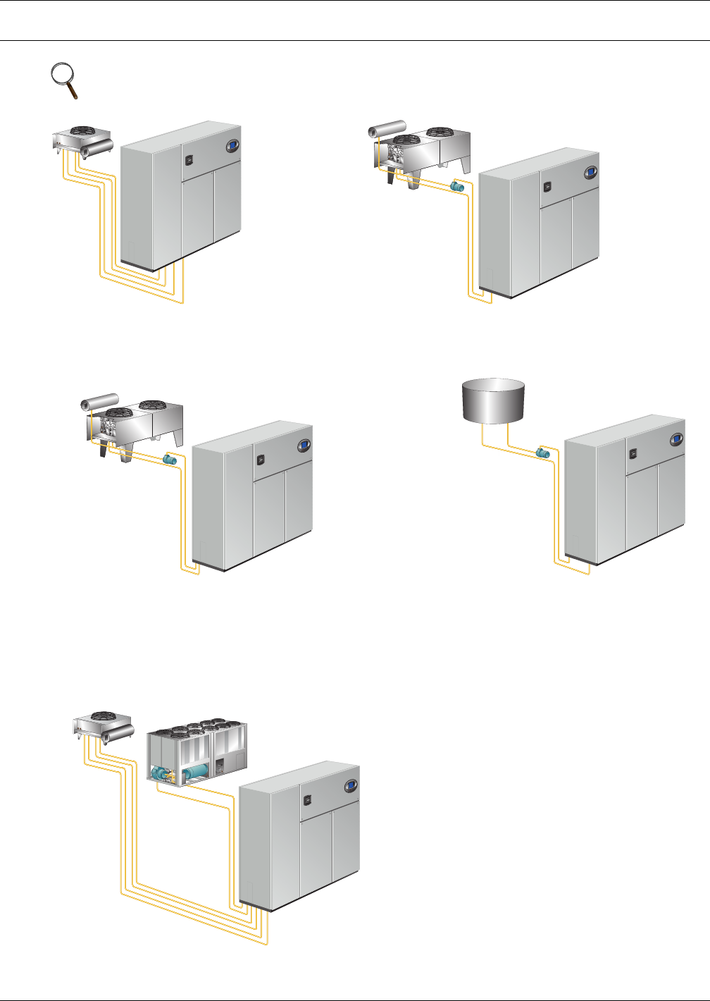
1.0 COOLING CONFIGURATIONS
NOTE
All field-installed piping must comply with applicable local, state and federal codes.
AIR-COOLED
Air-cooled unit piping is spun closed from the
factory and contains a nitrogen holding charge.
Each installation requires field-supplied
refrigerant and piping to a condenser.
GLYCOL-COOLED
Glycol-cooled units are factory-charged and
tested. Field-supplied and field-installed piping is
required from the unit to the drycooler and pump
package.
WATER-COOLED
Water-cooled units are factory-charged and
tested. Field-supplied and field-installed
water piping is required from the unit to the
cooling tower.
GLYCOOL-INTEGRATED FLUID ECONOMIZER
GLYCOOL units are factory-charged and tested. Field-supplied
and field-installed piping is required from the unit to the
drycooler and pump package. An additional Liebert Economizer
coil is included for use when fluid temperatures are sufficiently
low (below room temperature). Economizer cooling is provided
by circulating cold glycol through this second coil, reducing or
eliminating compressor operation.
DUAL-COOL
This system has all of the features of a compressorized
system, but adds a second cooling coil that is connected
to a source of chilled water. Cooling is provided by
circulating chilled water, when available, through this
second coil and reducing compressor operation.
Blower Configurations
3Liebert
® DS™
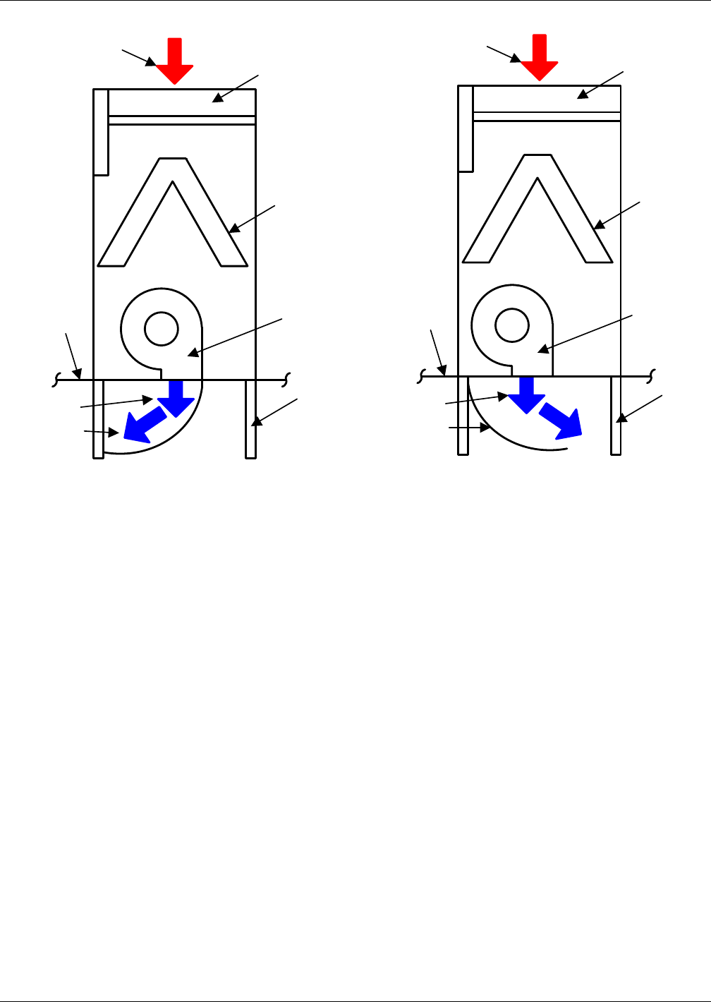
2.0 BLOWER CONFIGURATIONS
Figure 1 Blower configurations—Downflow, front and rear supply models, EC fans
Figure 2 Blower configurations—Downflow, bottom supply and under-floor supply models, EC fans
Front
Filter
Coil
Blower
Raised
Floor
Return Air
Supply
Air
Front Supply, EC Fans
Front
Filter
Coil
Blower
Raised
Floor
Return Air
Supply
Air
Rear Supply, EC Fans
Applicable to installations
without raised floors
Applicable to installations
without raised floors
Front
Filter
Coil
Blower
Floor
Stand
(optional)
Raised
Floor
Return Air
Supply
Air
Front
Filter
Coil
Blower
Floor Stand
(optional )
Raised
Floor
Return Air
Supply Air Supply
Air
Under-Floor Supply, EC Fans
Bottom Supply, EC Fans
Blower Configurations
Liebert® DS™4
Figure 3 Blower configurations—Downflow, front and rear supply models, centrifugal fans
Front
Filter
Coil
Blower
Floor
Stand
(optional)
Raised
Floor
Return Air
Supply Air
Turning Vane
(optional )
Front Supply, Forward-Curved Fans
Front
Filter
Coil
Blower
Floor
Stand
(optional)
Raised
Floor
Return Air
Supply Air
Turning Vane
(optional )
Rear Supply, Forward-Curved Fans
Blower Configurations
5Liebert
® DS™
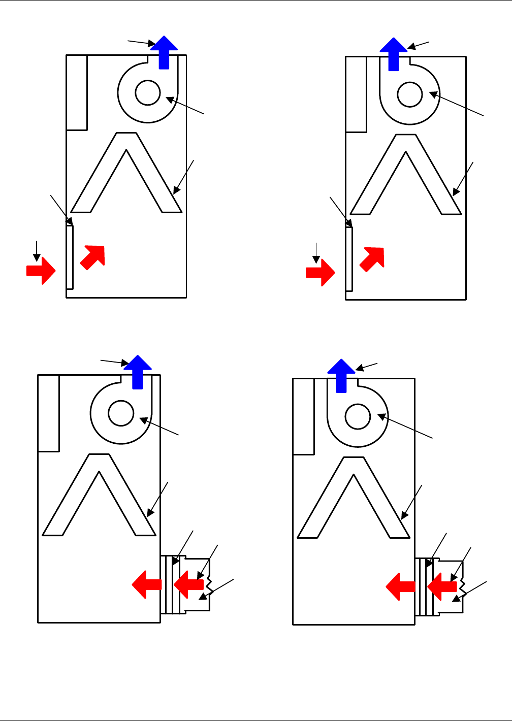
Figure 4 Blower configurations—Upflow, front return models, centrifugal fans
Figure 5 Blower configurations—Upflow, rear return models, centrifugal fans
Front
Coil
Return
Air
Supply Air
Blower
Filter
Front
Coil
Return
Air
Supply Air
Blower
Filter
Top Supply, Front Throw Forward-Curved Fans Top Supply, Rear Throw Forward-Curved Fans
Front
Coil
Supply Air
Blower
Filter
Return
Air
Ductwork
Front
Coil
Supply Air
Blower
Filter
Return
Air
Ductwork
Top Supply, Rear Throw, Forward-Curved FansTop Supply, Front Throw, Forward-Curved Fans
Air-Cooled Systems
Liebert® DS™6
3.0 AIR-COOLED SYSTEMS
3.1 CAPACITY AND PHYSICAL DATA
Table 1 Performance Data—Air-cooled, EC fan, under-floor discharge
Model Size 028 035 042 053 070 077 105
CAPACITY DATA with EC Fans
Net Capacity Data kW (BTUH), Standard Air Volume and Evaporator Fan Motor
Semi Hermetic Compressors with EC Fans
85°F DB, 64.5°F WB, 52.3°F DP (29.4°C DB, 18.1°C WB) 32.4% RH
Total kW (kBTUH) 34.1 (116.4) 42.1 (143.6) 47.9 (163.6) 61.7 (210.6) 72.4 (247.1) 79.2 (270.3) 103.3 (352.5)
Sensible kW
(kBTUH) 34 (116) 41.4 (141.2) 47.9 (160.9) 61.6 (210.2) 72 (245.9) 78.9 (269.2) 98.9 (337.5)
80°F DB, 62.9°F WB, 52.3°F DP (26.7°C DB, 17.1°C WB) 38.2% RH
Total kW (kBTUH) 32.4 (110.5) 40.1 (136.8) 45.7 (156.1) 58.3 (198.9) 68.8 (234.8) 75.3 (257.1) 99.1 (338.2)
Sensible kW
(kBTUH) 31 (105.9) 37.5 (128.1) 45.7 (146.2) 56.8 (193.9) 66.4 (226.6) 72.9 (248.8) 90 (307.2)
75°F DB, 61.1°F WB, 52.3°F DP (23.9°C DB, 16.2°C WB) 45.1% RH
Total kW (kBTUH) 30.9 (105.3) 38.3 (130.8) 43.8 (149.5) 55.4 (189) 65.6 (223.9) 72 (245.8) 95.2 (325)
Sensible kW
(kBTUH) 27.5 (93.9) 33.3 (113.8) 43.8 (129.9) 50.8 (173.3) 59 (201.3) 64.9 (221.5) 80 (273.1)
72°F DB, 60.0°F WB, 52.3°F DP (22.2°C DB, 15.6°C WB) 49.9% RH
Total kW (kBTUH) 30 (102.5) 37.3 (127.4) 42.7 (145.8) 53.8 (183.6) 63.9 (218) 70.2 (239.7) 93.1 (317.6)
Sensible kW
(kBTUH) 25.3 (86.3) 30.7 (104.8) 42.7 (119.7) 46.7 (159.3) 54.2 (184.9) 59.7 (203.6) 73.8 (251.8)
Net Capacity Data kW (BTUH), Standard Air Volume and Evaporator Fan Motor
Scroll or Digital Scroll Compressors with EC Fans Scroll Compressors Only
85°F DB, 64.5°F WB, 52.3°F DP (29.4°C DB, 18.1°C WB) 32.4% RH
Total kW (kBTUH) 35.4 (120.8) 40.2 (137.1) 45.5 (155.3) 63.5 (216.8) 75.8 (258.6) 81.3 (277.6) 103.6 (353.7)
Sensible kW
(kBTUH) 35.2 (120) 40 (136.4) 45.3 (154.7) 63.2 (215.7) 74.9 (255.6) 80.6 (275.1) 99.1 (338.3)
80°F DB, 62.9°F WB, 52.3°F DP (26.7°C DB, 17.1°C WB) 38.2% RH
Total kW (kBTUH) 33.4 (113.9) 38.2 (130.4) 43.4 (148.1) 60.5 (206.5) 72.7 (248) 77.9 (265.8) 99.7 (340.2)
Sensible kW
(kBTUH) 31.8 (108.7) 36.5 (124.6) 41.6 (141.9) 58.3 (199.1) 68.9 (235) 74.1 (253) 90.3 (308.2)
75°F DB, 61.1°F WB, 52.3°F DP (23.9°C DB, 16.2°C WB) 45.1% RH
Total kW (kBTUH) 31.6 (107.8) 36.5 (124.7) 41.6 (141.9) 57.8 (197.4) 69.9 (238.4) 74.9 (255.5) 96 (327.8)
Sensible kW
(kBTUH) 28.2 (96.1) 32.5 (110.8) 37 (126.3) 52 (177.6) 61.4 (209.4) 65.9 (224.9) 80.4 (274.3)
72°F DB, 60.0°F WB, 52.3°F DP (22.2°C DB, 15.6°C WB) 49.9% RH
Total kW (kBTUH) 30.6 (104.3) 35.6 (121.5) 40.6 (138.5) 56.4 (192.6) 68.3 (233) 73.2 (249.9) 93.8 (320.3)
Sensible kW
(kBTUH) 25.8 (88.2) 29.9 (102.1) 34.1 (116.3) 47.9 (163.6) 56.5 (192.9) 60.6 (206.9) 74.1 (253)
FAN SECTION - Downflow Models - EC Fans Under Floor
Standard Air
Volume,
CFM (CMH)
0.2" External Static
4,400
(7,476)
5,200
(8,835)
6200
(10533.9)
8,000
(13,592)
9,600
(16,310)
11,000
(18,689)
13,700
(23,276)
Standard Fan
Motor,
Nominal kW
(total for all fans)
2.8 2.8 2.8 2.5 4.0 5.9 7.8
Number of Fans 1 1 1 2 2 2 3
1. Capacity data is rated and factory-certified per ASHRAE 127-2012 with a 5% tolerance.
2. Some options or combinations of options may result in reduced air flow—consult factory for recommendations.
3. Digital scroll not available on 077 and 105 models; units available with semi-hermetic and standard scroll compressors only.
Air-Cooled Systems
7Liebert
® DS™
Table 2 Performance data—Air-cooled, centrifugal fan
Model Size 028 035 042 053 070 077 105
CAPACITY DATA with Centrifugal Fans
Net Capacity Data kW (BTUH), Standard Air Volume and Evaporator Fan Motor
Semi Hermetic Compressors with Centrifugal Fans
85°F DB, 64.5°F WB, 52.3°F DP (29.4°C DB, 18.1°C WB) 32.4% RH
Total kW (kBTUH) 40.3 (137.6) 41.0 (140.0) 46.2 (157.6) 60.2 (205.3) 70.5 (240.6) 76.9 (262.6) 101.3 (345.6)
Sensible kW
(kBTUH) 38.0 (129.6) 40.3 (137.6) 45.5 (155.3) 59.7 (203.8) 69.7 (237.9) 76.2 (259.9) 96.6 (329.6)
80°F DB, 62.9°F WB, 52.3°F DP (26.7°C DB, 17.1°C WB) 38.2% RH
Total kW (kBTUH) 38.6 (131.8) 39.1 (133.3) 43.9 (150) 57.2 (195.1) 67.2 (229.3) 73.4 (250.6) 97.1 (331.5)
Sensible kW
(kBTUH) 34.3 (117.2) 36.5 (124.6) 41.2 (140.5) 54.8 (187.1) 63.8 (217.7) 69.8 (238.2) 87.7 (299.4)
75°F DB, 61.1°F WB, 52.3°F DP (23.9°C DB, 16.2°C WB) 45.1% RH
Total kW (kBTUH) 37.1 (126.5) 37.3 (127.2) 42 (143.3) 54.4 (185.6) 64.1 (218.9) 70.2 (239.7) 93.3 (318.4)
Sensible kW
(kBTUH) 30.5 (104.2) 32.3 (110.3) 36.4 (124.2) 48.7 (166.2) 56.5 (192.9) 61.8 (210.9) 77.8 (265.4)
72°F DB, 60.0°F WB, 52.3°F DP (22.2°C DB, 15.6°C WB) 49.9% RH
Total kW (kBTUH) 36.1 (123.3) 36.3 (123.8) 40.9 (139.6) 52.9 (180.6) 62.5 (213.2) 68.6 (234) 91.0 (310.6)
Sensible kW
(kBTUH) 28.2 (96.3) 29.7 (101.3) 33.4 (113.9) 44.7 (152.7) 51.9 (177.2) 56.7 (193.6) 71.5 (244.1)
Net Capacity Data kW (BTUH), Standard Air Volume and Evaporator Fan Motor
Scroll or Digital Scroll Compressors with Centrifugal Fans Scroll Compressors Only
85°F DB, 64.5°F WB, 52.3°F DP (29.4°C DB, 18.1°C WB) 32.4% RH
Total kW (kBTUH) 34.1 (116.4) 39.7 (135.5) 43.7 (149.2) 62.1 (212.1) 74.0 (252.6) 79.1 (270.1) 101.6 (346.9)
Sensible kW
(kBTUH) 40.1 (136.9) 34.0 (116.0) 43.6 (148.9) 61.3 (209.3) 72.3 (246.6) 77.8 (265.6) 96.8 (330.4)
80°F DB, 62.9°F WB, 52.3°F DP (26.7°C DB, 17.1°C WB) 38.2% RH
Total kW (kBTUH) 32.4 (110.5) 38.3 (130.8) 41.6 (141.9) 59.3 (202.5) 71.2 (243) 75.9 (259) 97.7 (333.5)
Sensible kW
(kBTUH) 31.0 (105.9) 36.1 (123.2) 39.9 (136.1) 56.1 (191.6) 65.9 (225) 71.1 (242.6) 88.0 (300.4)
75°F DB, 61.1°F WB, 52.3°F DP (23.9°C DB, 16.2°C WB) 45.1% RH
Total kW (kBTUH) 30.9 (105.3) 36.7 (125.4) 39.8 (135.7) 56.9 (194.2) 68.5 (233.9) 73 (249.3) 94.1 (321.1)
Sensible kW
(kBTUH) 27.5 (93.9) 32.1 (109.4) 35.3 (120.6) 49.9 (170.4) 58.6 (200.1) 63.1 (215.2) 78.1 (266.6)
72°F DB, 60.0°F WB, 52.3°F DP (22.2°C DB, 15.6°C WB) 49.9% RH
Total kW (kBTUH) 30.0 (102.5) 35.9 (122.4) 38.8 (132.3) 55.5 (189.5) 67 (228.7) 71.4 (243.7) 91.9 (313.7)
Sensible kW
(kBTUH) 25.3 (86.3) 29.5 (100.6) 32.4 (110.5) 46.0 (157) 54.0 (184.3) 58.0 (197.8) 71.9 (245.5)
FAN SECTION - Downflow Models - Fixed Pitch, Two Belts
Standard Air
Volume - CFM
(CMH) 0.2"
external static
4,400
(7,476)
5,200
(8,835)
6,300
(10,704)
7,500
(12,743)
9,000
(15,291)
10,400
(17,670)
13,700
(23,276)
Standard Fan
Motor hp (kW) 2 (1.5) 3 (2.2) 5.0 (3.7) 3 (2.2) 5 (3.7) 7.5 (5.6) 10.0 (7.5)
Number of Fans 1 1 1 2 2 2 3
1. Capacity data is rated and factory-certified per ASHRAE 127-2012 with a 5% tolerance.
2. Some options or combinations of options may result in reduced air flow—consult factory for recommendations.
3. Digital scroll not available on 077 and 105 models; units available with semi-hermetic and standard scroll compressors only
Air-Cooled Systems
Liebert® DS™8
Table 3 Physical data—Air-cooled systems
Model Size 028 035 042 053 070 077 105
EVAPORATOR COIL- A-Frame - Copper Tube/Aluminum Fin
Face Area, sq. ft. (sq. m) 17.1 (1.6) 17.1 (1.6) 17.1 (1.6) 24.7 (2.3) 24.7 (2.3) 24.7 (2.3) 32.3 (3.0)
Rows of Coil 333 3 3 3 3
REHEAT SECTION
Electric Reheat - Three-Stage, Stainless Steel Fin Tubular, capacity does not include fan motor heat
Capacity - kW (kBTUH) - Standard
Selection 15.0 (51.2) 15.0 (51.2) 15.0 (51.2) 25.0 (85.3) 25.0 (85.3) 25.0 (85.3) 30.0 (102.4)
Capacity, kW (kBTUH) - Optional
Selection 10.0 (34.1) 10.0 (34.1) 10.0 (34.1) 15.0 (51.2) 15.0 (51.2) 15.0 (51.2) 20.0 (68.3)
Electric Reheat - SCR Control, Stainless Steel Fin Tubular (optional selection)
Capacity, kW (kBTUH) 15.0 (51.2) 15.0 (51.2) 15.0 (51.2) 25.0 (85.3) 25.0 (85.3) 25.0 (85.3) 30.0 (102.4)
HUMIDIFIER SECTION
Infrared Humidifier (Steam canister humidifiers available on downflow models with centrifugal fans)
Capacity, lb./hr. (kg/h) 11.0 (5.0) 11.0 (5.0) 11.0 (5.0) 22.0 (10.0) 22.0 (10.0) 22.0 (10.0) 22.0 (10.0)
FILTER SECTION - Disposable Type - Nominal Sizes and Quantities, Standard MERV 8 or Optional MERV 11
(filter types cannot be mixed, must be all MERV 8 or all MERV 11)
Downflow Models
Quantity 333 4 4 4 4
Nominal Size, inches 2 @ 25x20
1 @ 25x16
2 @ 25x20
1 @ 25x16
2 @ 25x20
1 @ 25x16 4 @ 25x20 4 @ 25x20 4 @ 25x20 4 @ 25x20
Upflow Models (Front & Rear return) Filters located in separate filter box on rear return, located on lower unit panel
Quantity 444 6 6 6 8
Nominal Size, inches 25x20 25x20 25x20 25x20 25x20 25x20 25x20
PIPING CONNECTION SIZES - Air-cooled Liebert DS Indoor Unit (Not External Line Sizes)
Liquid Line, O.D. Copper (2/unit) 1/2 1/2 1/2 5/8 5/8 5/8 5/8
Hot Gas Line, O.D. Copper (2/unit) 5/8 5/8 5/8 7/8 7/8 7/8 1-1/8
Infrared Humidifier, O.D. Copper 1/4 1/4 1/4 1/4 1/4 1/4 1/4
Condensate Drain, FPT 3/4 3/4 3/4 3/4 3/4 3/4 3/4
Condensate Drain w/Optional
Condensate Pump, OD 1/2 1/2 1/2 1/2 1/2 1/2 1/2
OUTDOOR AIR-COOLED CONDENSER, STANDARD 95°F AMBIENT SELECTION; see Tables 44 and 49 for other selections
Model (R-407C refrigerant) MCM080_8 MCM080_8 MCM080_8 MCM080_8 MCM080_8 MCM080_8 MCL110_8
Number of Fans 222 2 2 2 2
DUAL-COOL UNITS DATA, Water (0% Glycol), Net Capacity Data kW (kBTUH)
CAUTION: CuNi coil option must be specified when Econ-O-Coil is applied to open water tower.
75°F DB, 61.1 WB (23.9°C DB, 16.2°C WB) 45% RH, 45°F EWT, 55°F LWT Based on Centrifugal Fans
Total Capacity, kW (kBTUH) 26.2 (89.2) 29.8 (101.6) 32.2 (109.8) 49.9 (170.4) 55.3 (188.8) 57.7 (196.8) 75.8 (258.8)
Sensible Capacity, kW (kBTUH) 24.9 (85) 28.8 (98.2) 31.6 (107.8) 46 (157.1) 51.7 (176.4) 54.3 (185.4) 73 (249.1)
Flow Rate GPM (I/m) @ 10°F Rise 19 (71.9) 22.4 (84.8) 25.5 (96.5) 36.4 (138) 41.7 (158) 46 (174) 59.4 (225)
Pressure Drop, ft. (kPa), valve, coil 6.1 (18.23) 8.3 (24.81) 10.50 (31.39) 10.40 (31.09) 13.3 (39.8) 15.9 (47.6) 15.9 (47.5)
Airflow, CFM (CMH) 4400 (7475) 5500 (9344) 6600
(11213)
8000
(13592)
9600
(16310)
11000
(18689)
13,700
(23,256)
Fluid Volumes
Econ-O-Coil fluid volume, gal (l) 5 (19.0) 5 (19.0) 5 (19.0) 8 (30.4) 8 (30.4) 8 (30.4) 10 (38.0)
Capacity data is rated per ASHRAE 127-2012 with a 5% tolerance

Air-Cooled Systems
9Liebert
® DS™
Table 4 Electrical data—Air-cooled systems with EC fans
Model
#
Reheat
Options
Electric
Standard, kW None
Electric
Standard kW None
Electric,
Downsized kW
Electric,
Downsized kW
Humid-
ifier
Options Infrared Infrared None None Humidifier No Humidifier
Volts 208 230 460 575 208 230 460 575 208 230 460 575 208 230 460 575 208 230 460 575 208 230 460 575
DS028
FLA 67.3 64.8 32.1 25.5 56.3 54.1 26.9 24.2 67.3 64.8 32.1 25 43 43 21.1 16.8 56.3 54.1 26.9 24.2 53.5 51.9 25.6 19.9
WSA 82 78.9 39.2 31.9 60.6 58.4 29.1 25.9 82 78.9 39.2 30.5 47.3 47.3 23.3 18.5 64.8 62.8 31.1 25.9 64.8 62.8 31.1 24.1
OPD 80804030707035308080403060 6030
25 70 70 35 30 70 70 35 25
DS035
FLA 70.7 68.2 33.4 25.5 63.1 60.9 29.5 25.2 70.7 68.2 33.4 25.5 49.8 49.8 23.7 17.8 63.1 60.9 29.5 25.2 56.9 55.3 26.9 20.4
WSA 86.3 83.2 40.8 31.9 68.3 66.1 32 27.1 86.3 83.2 40.8 31.1 55 55 26.2 19.7 69 67 32.7 27.1 69 67 32.7 24.8
OPD 90904530808040309090453070 7035
25 80 80 40 30 80 80 35 25
DS042
FLA 78.2 75.9 37.7 33 78.1 75.9 37.7 33 78.2 75.7 37.5 29.4 64.8 64.8 31.9 25.6 78.1 75.9 37.7 33 64.8 64.8 31.9 25.6
WSA 95.7 92.5 46 36 85.2 83 41.2 35.8 95.7 92.5 46 36 71.9 71.9 35.4 28.4 85.2 83 41.2 35.8 78.4 76.4 37.8 29.6
OPD 110 110 50 45 110 110 50 45 110 110 50 40 100 100 45 35 110 110 50 45 100 100 45 35
DS053
FLA 119.9 116 57.1 43.5 109.2 104.8 52.4 42 119.9 116 57.1 43.5 82.6 82.6 40.8 30.4 109.2 104.8 52.4 42 92.1 89.6 44.1 33.5
WSA 145.3 140.4 69.4 53.9 117.2 112.8 56.5 45 145.3 140.4 69.4 52.8 90.6 90.62 44.9 33.4 117.2 112.8 56.5 45 110.52 107.4 53.1 40.3
OPD 150 150 70 50 125 125 70 50 150 150 70 50 110 110 60 45 125 125 70 50 125 125 60 45
DS070
FLA 129.2 125.3 59.9 46.4 127.8 123.4 58 46.4 129.2 125.3 59.9 45.7 101.2 101.2 46.4 34.8 127.8 123.4 58 46.4 101.4 101.2 46.9 35.7
WSA 156.9 152 72.9 55.5 138.2 133.8 62.8 50 156.9 152.0 72.9 55.5 111.6 111.6 51.2 38.4 138.2 133.8 62.8 50 122.15 119.02 56.6 43
OPD 175 175 80 60 175 175 80 60 175 175 80 60 150 150 70 50 175 175 80 60 150 150 70 50
DS077
FLA 139.2 134.8 61.4 50 139.2 134.8 61 50 134.9 131 61.4 47.5 112.6 112.6 49.4 38.4 139.2 134.8 61 50 112.6 112.6 49.4 38.4
WSA 164 159.2 74.8 57.8 151. 146.6 66.2 54 164.0 159.2 74.8 57.8 124.37 124.4 54.6 42.4 151 146.6 66.2 54 129.27 126.15 58.5 45.3
OPD 175 175 80 70 175 175 80 70 175 175 80 60 150 150 70 50 175 175 80 70 150 150 70 50
DS105
FLA 171.5 167.1 83.7 69.1 171.5 167.1 83.7 69.1 164 163.5 79.8 62.6 144.9 144.9 72.1 57.5 171.5 167.1 83.7 69.1 144.9 144.9 72.1 57.5
WSA 198.8 198.2 97.4 76.4 186.5 182.1 91.6 75.4 198.8 198.2 97.4 76.4 159.9 159.9 80 63.8 186.5 182.1 91.6 75.4 169.3 165.5 81.3 63.9
OPD 225 225 110 100 225 225 110 100 225 225 110 90 200 200 110 80 225 225 110 100 200 200 110 80
1. Reduced reheat for 028, 035, and 042 models is 10kW.
2. Reduced reheat for 053, 070, and 077 models is 15kW.
3. Consult local representative for SCR reheat values.
4. Reduced reheat for 105 kW models is 20kW.
5. SCCR - Short Circuit Current Rating 65,000 amps rms symmetrical maximum.
6. Steam canister humidifiers not available on models with EC fans.
Air-Cooled Systems
Liebert® DS™10
Table 5 Electrical data—Air-cooled systems with centrifugal fans
Reheat Options Electric, Std. kW None Electric, Std. kW None
Humidifier
Options
Infrared or Steam
Generating Canister
Infrared or Steam
Generating Canister None None
Model
Motor
hp Volts 208 230 460 575 208 230 460 575 208 230 460 575 208 230 460 575
028 2.0
FLA 66.4 63.2 31.8 25.2 55.4 52.5 26.6 23.9 66.4 63.2 31.8 24.7 42.1 41.4 20.8 16.5
WSA 81.1 77.3 38.9 31.5 59.7 56.8 28.8 25.6 81.1 77.3 38.9 30.2 46.4 45.7 23 18.2
OPD80804030707035308080403060603025
028 3.0
FLA 69.5 66.0 33.2 26.4 58.5 55.3 28.0 25.1 69.5 66.0 33.2 25.9 45.2 44.2 22.2 17.7
WSA 84.2 80.1 40.3 33 62.8 59.6 30.2 26.8 84.2 80.1 40.3 31.4 49.5 48.5 24.4 19.4
OPD90804030807035309080403060603025
035 3.0t
FLA 72.9 69.4 34.5 26.4 65.3 62.1 30.6 26.1 72.9 69.4 34.5 26.4 52.0 51.0 24.8 18.7
WSA 88.5 84.4 41.9 33.0 70.5 67.3 33.1 28.0 88.5 84.4 41.9 32.0 57.2 56.2 27.3 20.6
OPD90904535908040359090453570703525
035 5.0
FLA 79.0 75.0 37.3 28.6 71.4 67.7 33.4 28.3 79.0 75.0 37.3 28.6 58.1 56.6 27.6 20.9
WSA 94.6 90.0 44.7 35.8 76.6 72.9 35.9 30.2 94.6 90.0 44.7 34.2 63.3 61.8 30.1 22.8
OPD 100 100 45 35 90 90 45 35 100 100 45 35 80 80 40 30
042 5.0
FLA 86.5 82.7 41.6 36.1 86.4 82.7 41.6 36.1 86.5 82.5 41.4 32.5 73.1 71.6 35.8 28.7
WSA 104 99.3 49.9 39.1 93.5 89.8 45.1 38.9 104.0 99.3 49.9 39.1 80.2 78.7 39.3 31.5
OPD 110 110 50 50 110 110 50 50 110 110 50 45 100 100 50 40
042 7.5
FLA 94.0 89.5 45.0 39.0 93.9 89.5 45.0 39.0 94.0 89.3 44.8 35.4 80.6 78.4 39.2 31.6
WSA 111.5 106.1 53.3 42.0 101.0 96.6 48.5 41.8 111.5 106.1 53.3 42.0 87.7 85.5 42.7 34.4
OPD 125 110 60 50 125 110 60 50 125 110 60 45 110 110 50 45
053 3.0
FLA 112.1 107.2 53.9 41 101.4 96 49.2 39.5 112.1 107.2 53.9 41 74.8 73.8 37.6 27.9
WSA 137.5 131.6 66.2 50.8 109.4 104.0 53.3 42.5 137.5 131.6 66.2 50.3 82.8 81.8 41.7 30.9
OPD 150 125 70 50 125 125 60 50 150 125 70 50 110 110 50 40
053 5.0
FLA 118.2 112.8 56.7 43.2 107.5 101.6 52.0 41.7 118.2 112.8 56.7 43.2 80.9 79.4 40.4 30.1
WSA 143.6 137.2 69.0 53.5 115.5 109.6 56.1 44.7 143.6 137.2 69.0 52.5 88.9 87.4 44.5 33.1
OPD 150 150 70 50 125 125 70 50 150 150 70 50 110 110 60 45
070 5.0
FLA 127.5 122.1 59.5 46.1 126.1 120.2 57.6 46.1 127.5 122.1 59.5 45.4 99.5 98 46 34.5
WSA 155.2 148.8 72.5 55.2 136.5 130.6 62.4 49.7 155.2 148.8 72.5 55.2 109.9 108.4 50.8 38.1
OPD 175 150 80 60 175 150 80 60 175 150 80 60 150 125 70 50
070 7.5
FLA 135.0 128.9 62.9 49.0 133.6 127.0 61.0 49.0 135.0 128.9 62.9 48.3 107.0 104.8 49.4 37.4
WSA 162.7 155.6 75.9 58.1 144.0 137.4 65.8 52.6 162.7 155.6 75.9 58.1 117.4 115.2 54.2 41.0
OPD 175 175 80 60 175 175 80 60 175 175 80 60 150 150 70 50
077 7.5
FLA 145 138.4 64.4 52.6 145.0 138.4 64.0 52.6 140.7 134.6 64.4 50.1 118.4 116.2 52.4 41.0
WSA 169.8 162.8 77.8 60.4 156.8 150.2 69.2 56.6 169.8 162.8 77.8 60.4 130.2 128.0 57.6 45.0
OPD 200 175 90 70 200 175 80 70 175 175 90 70 175 175 70 60
077 10.0
FLA 151.6 144.4 67.4 54.6 151.6 144.4 67.0 54.6 147.3 140.6 67.4 52.1 125.0 122.2 55.4 43.0
WSA 176.4 168.8 80.8 62.4 163.4 156.2 72.2 58.6 176.4 168.8 80.8 62.4 136.8 134.0 60.6 47.0
OPD 200 200 90 70 200 200 90 70 200 175 90 70 175 175 80 60
105 10.0
FLA 177.4 170.2 88.4 72.6 177.4 170.2 88.4 72.6 169.9 166.6 84.5 66.1 150.8 148 76.8 61.0
WSA 204.7 201.3 102.1 79.9 204.7 201.3 102.1 79.9 204.7 201.3 102.1 79.9 165.8 163.0 84.7 67.3
OPD 250 225 125 100 250 225 125 100 225 225 110 90 225 200 110 90
105 15.0
FLA 192.3 184.2 95.4 78.6 192.3 184.2 95.4 78.6 185.3 180.6 91.5 72.1 166.2 162.0 83.8 67.0
WSA 220.1 215.3 109.1 85.9 220.1 215.3 109.1 85.9 220.1 215.3 109.1 85.9 181.2 177.0 91.7 73.3
OPD 250 250 125 100 250 250 125 100 250 250 125 100 225 225 110 90
1. Reduced reheat for 028, 035, and 042 models is 10kW.
2. Reduced reheat for 053, 070, and 077 models is 15kW.
3. Consult local representative for SCR reheat values.
4. Reduced reheat for 105 kW models is 20kW.
5. SCCR - Short Circuit Current Rating 65,000 amps rms symmetrical maximum.
Air-Cooled Systems
11 Liebert® DS™
Table 5 Electrical data—Air-cooled systems with centrifugal fans (continued)
Reheat Options Electric, Downsized kW
Humidifier Options Infrared or Steam Generating Canister None
Model Motor, hp Volts 208 230 460 575 208 230 460 575
028 2.0
FLA 55.4 52.5 26.6 23.9 52.6 50.3 25.3 19.6
WSA 63.9 61.2 30.8 25.6 63.9 61.2 30.8 23.8
OPD 70 70 35 30 70 70 35 25
028 3.0
FLA 58.5 55.3 28 25.1 55.7 53.1 26.7 20.8
WSA 67.0 64.0 32.2 26.8 67.0 64.0 32.2 25.0
OPD 80 70 35 30 70 70 35 25
035 3.0
FLA 65.3 62.1 30.6 26.1 59.1 56.5 28.0 21.3
WSA 71.2 68.2 33.8 28.0 71.2 68.2 33.8 25.7
OPD 90 80 40 35 80 80 40 30
035 5.0
FLA 71.4 67.7 33.4 28.3 65.2 62.1 30.8 23.5
WSA 77.3 73.8 36.6 30.2 77.3 73.8 36.6 27.9
OPD 90 90 45 35 90 80 40 30
042 5.0
FLA 86.4 82.7 41.6 36.1 73.1 71.6 35.8 28.7
WSA 93.5 89.8 45.1 38.9 86.7 83.2 41.7 32.7
OPD 110 110 50 50 100 100 50 40
042 7.5
FLA 93.9 89.5 45.0 39.0 80.6 78.4 39.2 31.6
WSA 101.0 96.6 48.5 41.8 94.2 90.0 45.1 35.6
OPD 125 110 60 50 110 110 50 45
053 3.0
FLA 101.4 96.0 49.2 39.5 84.3 80.8 40.9 31
WSA 109.4 104.0 53.3 42.5 102.7 98.6 49.9 37.8
OPD 125 125 60 50 110 110 60 45
053 5.0
FLA 107.5 101.6 52.0 41.7 90.4 86.4 43.7 33.2
WSA 115.5 109.6 56.1 44.7 108.8 104.2 52.7 40.0
OPD 125 125 70 50 125 125 60 45
070 5.0
FLA 126.1 120.2 57.6 46.1 99.7 98 46.5 35.4
WSA 136.5 130.6 62.4 49.7 120.5 115.8 56.2 42.7
OPD 175 150 80 60 150 125 70 50
070 7.5
FLA 133.6 127.0 61.0 49.0 107.2 104.8 49.9 38.3
WSA 144.0 137.4 65.8 52.6 128.0 122.6 59.6 45.6
OPD 175 175 80 60 150 150 70 50
077 7.5
FLA 145 138.4 64.0 52.6 118.4 116.2 52.4 41.0
WSA 156.8 150.2 69.2 56.6 135.1 129.8 61.5 47.9
OPD 200 175 80 70 175 175 70 60
077 10.0
FLA 151.6 144.4 67.0 54.6 125.0 122.2 55.4 43.0
WSA 163.4 156.2 72.2 58.6 141.7 135.8 64.5 49.9
OPD 200 200 90 70 175 175 80 60
105 10.0
FLA 177.4 170.2 88.4 72.6 150.8 148 76.8 61.0
WSA 192.4 185.2 96.3 78.9 175.2 168.6 86.0 67.4
OPD 250 225 125 100 225 200 110 90
105 15.0
FLA 192.8 184.2 95.4 78.6 166.2 162.0 83.8 67.0
WSA 207.8 199.2 103.3 84.9 190.6 182.6 93.0 73.4
OPD 250 250 125 100 225 225 110 90
1. Reduced reheat for 028, 035, and 042 models is 10kW.
2. Reduced reheat for 053, 070, and 077 models is 15kW.
3. Consult local representative for SCR reheat values.
4. Reduced reheat for 105 kW models is 20kW.
5. SCCR - Short Circuit Current Rating 65,000 amps rms symmetrical maximum.
Air-Cooled Systems
Liebert® DS™12
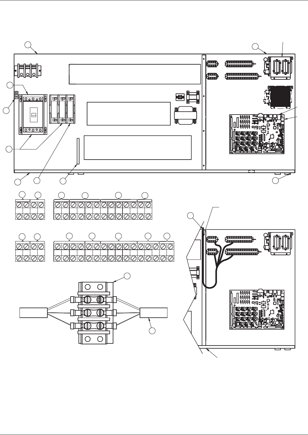
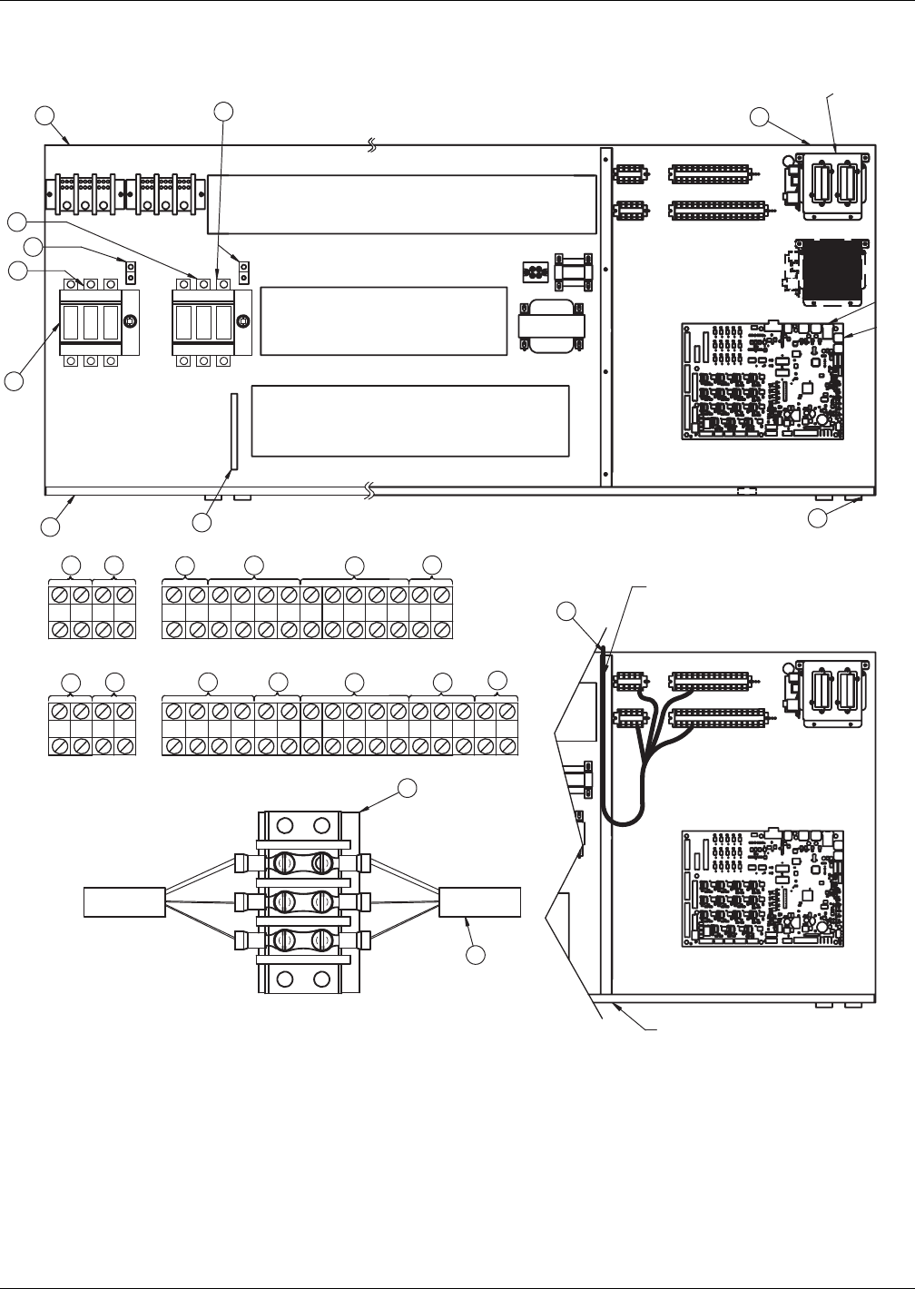
Figure 6 Electrical field connections—Upflow and downflow models, single molded case switch
disconnect with main fuses
75 76 94 95 96 97 91 11 12
92 93 80 81
73
37C 38C 37B 38B 37 38 24 70 71 230
50 51 55 56
88
83
82 89
84
59
58 85
Alternate
Location
72
17 18 916 19
20
10
8
21
23
24
22
7
3
1
13
6
15
24
AB
CD
AB
CD
P64
P67
6
60Hz
3
5
12
SH49-1
49-3
11
E
E
Liebert
IntelliSlot
Housing
Typical orientation of components shown.
Component location varies by option and unit size DOWNFLOW
UPFLOW
OVERCURRENT PROTECTION DEVICES
CONTACTORS
CONTACTORS, RELAYS, &
OVERLOAD PROTECTORS
DOWNFLOW LOW-VOLT SECTION
CAUTION
Risk of broken or shorted low-voltage
wiring. Field-installed low-voltage wiring
must be routed with loop as shown
to allow electric box to swing.
Item 12 Installation Conditions
1. Follow all local installation codes.
2. Do not run CAN cables in same conduit, raceway, or
chase as high voltage wires (120-600V).
3. Separate high-voltage wires from CAN wires by 12" (305mm).
4. For runs greater than 350ft (107m), contact Emerson factory.
Point of Hinged Low-Voltage Electric Box
DS UPFLOW LOW VOLT SECTION
DPN000807
Pg. 2, Rev. 8
See 3.2 - Standard Electrical Connections, 3.3 -
Optional Electrical Connections and 3.4 - Optional
Low-Voltage Terminal Package Connections for keys
to numbered components.
Air-Cooled Systems
13 Liebert® DS™
Figure 7 Electrical field connections—Upflow and downflow models, dual fused disconnect switches
75 76 94 95 96 97 91 11 12
92 93 80 81
72
37C38C37B38B 37 38 24 70 71 230
50 51 55 56
88
83
82 89
84
59
58 85
PRIMARY SECONDARY
Alternate
Location
Alternate
Location
73
17 18 916 19
20
10
8
21
23
24
22
7
3
1
13
6
15
14 4
AB
CD
AB
CD
P64
P67
6
60 Hz
3
15
2
12
SH49-1
49-3
11
E
E
OVERCURRENT PROTECTION DEVICES
CONTACTORS, RELAYS and
OVERLOAD PROTECTORS
Typical orientation of components shown.
Component location varies by option and unit size
DOWNFLOW
UPFLOW
DOWNFLOW LOW-VOLTAGE SECTION
Liebert
IntelliSlot
Housing
Item 12 Installation Conditions
1. Follow all local installation codes.
2. Do not run CAN cables in same conduit, raceway or
chase as high-voltage wires (120-600V).
3. Separate high-voltage wires from CAN wires by 12" (305mm).
4. Contact Liebert factory for runs greater than 350ft. (107m).
5. All electrical loads may not be capable of being connected to both
power feeds, with automatic transfer switch.
Consult local representative for dual power configurations available.
Point of Hinged Low-Voltage
Electric Box
DS UPFLOW LOW-VOLTAGE SECTION
DPN000807
Pg. 3, Rev. 8
CAUTION:
Risk of broken or shorted low-voltage
wiring. Field-installed low-voltage wiring
must be routed with loop as shown
to allow electric box to swing.
CONTACTORS
See 3.2 - Standard Electrical Connections, 3.3 -
Optional Electrical Connections and 3.4 - Optional
Low-Voltage Terminal Package Connections for keys
to numbered components.

Air-Cooled Systems
Liebert® DS™14
3.2 STANDARD ELECTRICAL CONNECTIONS
Source: DPN000807, Rev. 8
1. Primary high voltage entrance—2.5" (64mm); 1.75" (44mm); 1.375" (35mm) diameter
concentric knockouts located in bottom of box.
2. Secondary high voltage entrance—2.5" (64mm); 1.75" (44mm); 1.375" (35mm) diameter
concentric knockouts located in top of box.
3. Primary low voltage entrance—Quantity (3) 1.375" (35mm) diameter knockouts located in
bottom of unit.
4. Secondary low voltage entrance—Quantity (3) 1. 375" (35mm) diameter knockouts located in
top of box.
5. Three phase electrical service—Terminals are on main fuse block (disregard if unit has
optional disconnect switch). Three-phase service not by Emerson.
6. Earth ground—Terminal for field-supplied earth grounding wire. Earth grounding required for
Liebert units.
7. Remote unit shutdown—Replace existing jumper between Terminals 37 & 38 with
field-supplied normally closed switch having a minimum 75VA, 24VAC rating. Use field-supplied
Class 1 wiring.
8. Customer alarm inputs—Terminals for field-supplied, normally open contacts, having a
minimum 75VA, 24VAC rating, between Terminals 24 & 50, 51, 55 & 56. Use field-supplied
Class 1 wiring. Terminal availability varies by unit options.
9. Common alarm—On any alarm, normally open dry contact is closed across Terminals 75 & 76
for remote indication. 1A, 24VAC maximum load. Use Class 1 field-supplied wiring.
10. Heat rejection interlock—On any call for compressor operation, normally open dry contact is
closed across Terminals 70 & 71 (Circuit 1), 230 (Circuit 2) to heat rejection equipment. 1A,
24VAC maximum load. Use field-supplied Class 1 wiring. When a Liebert DS unit is paired with a
Liebert MC series condenser, remove jumper between Terminal 71 and Terminal 230. Three
wires must connect Terminals 70, 71 and 230 of the indoor unit to Terminals 70, 71 and 230 of the
Liebert MC series condenser.

Air-Cooled Systems
15 Liebert® DS™
3.3 OPTIONAL ELECTRICAL CONNECTIONS
Source: DPN000807, Rev. 8
11. Unit factory installed disconnect switch, Fuse Block and Main Fuses—Two types of
disconnect switches are available: Non-Locking and Locking. The Non-Locking Type consists of a
non-automatic molded case switch operational from the outside of the unit. Access to the
high-voltage electric panel compartment can be obtained with the switch in either the On or Off
position. The Locking Type is identical except access to the high-voltage electric panel
compartment can be obtained only with the switch in the Off position. Units with fused
disconnects are provided with a defeater button that allows access to the electrical panel when
power is On. The molded case switch disconnect models contain separate main fuses. Units with
fused disconnect have main fuses within the disconnect. Only fused disconnects are used on dual
disconnect options.
12. Secondary disconnect switch and earth ground
13. Three-phase electrical service—Terminals are on top of disconnect switch. Three-phase
service not by Emerson.
14. Smoke sensor alarm—Factory-wired dry contacts from smoke sensor are 91-common, 92-NO,
and 93-NC. Supervised contacts, 80 & 81, open on sensor trouble indication. This smoke sensor is
not intended to function as or replace any room smoke detection system that may be required by
local or national codes. 1A, 24VAC maximum load. Use field-supplied Class 1 wiring.
15. Reheat and humidifier lockout—Remote 24VAC required at Terminals 82 & 83 for lockout of
reheat and humidifier.
16. Condensate alarm (with condensate pump option)—On pump high water indication,
normally open dry contact is closed across Terminals 88 & 89 for remote indication. 1A, 24VAC
maximum load. Use field-supplied Class 1 wiring.
17. Remote humidifier—On any call for humidification, normally open dry contact is closed across
Terminals 11 & 12 to signal field-supplied remote humidifier. 1A, 24VAC maximum load. Use
Class 1 field-supplied wiring.
18. Auxiliary cool contact—On any call for Econ-O-coil operation, normally open dry contact is
closed across Terminals 72 & 73 on dual cool units only. 1A, 24VAC maximum load. Use
field-supplied Class 1 wiring.
3.4 OPTIONAL LOW-VOLTAGE TERMINAL PACKAGE CONNECTIONS
Source: DPN000807, Rev. 8
19. Remote unit shutdown—Two additional contact pairs available for unit shutdown (labeled as
37B & 38B, 37C and 38C). Replace jumpers with field-supplied, normally closed switch having a
minimum rating of 75VA, 24VAC. Use field-supplied Class 1 wiring.
20. Common alarm—On any alarm, two additional normally open dry contacts are closed across
Terminals 94 & 95 and 96 & 97 for remote indication. 1A, 24VAC maximum load. Use
field-supplied Class 1 wiring.
21. Main fan auxiliary switch—On closure of main fan contactor, normally open dry contact is
closed across Terminals 84 & 85 for remote indication. 1A, 24VAC maximum load. Use
field-supplied Class 1 wiring.
22. Liebert Liqui-tect™ shutdown and dry contact—On Liebert Liqui-tect activation, normally
open dry contact is closed across Terminals 58 & 59 for remote indication (Liebert Liqui-tect
sensor ordered separately). 1A, 24VAC maximum load. Use field-supplied Class 1 wiring.
Air-Cooled Systems
Liebert® DS™16
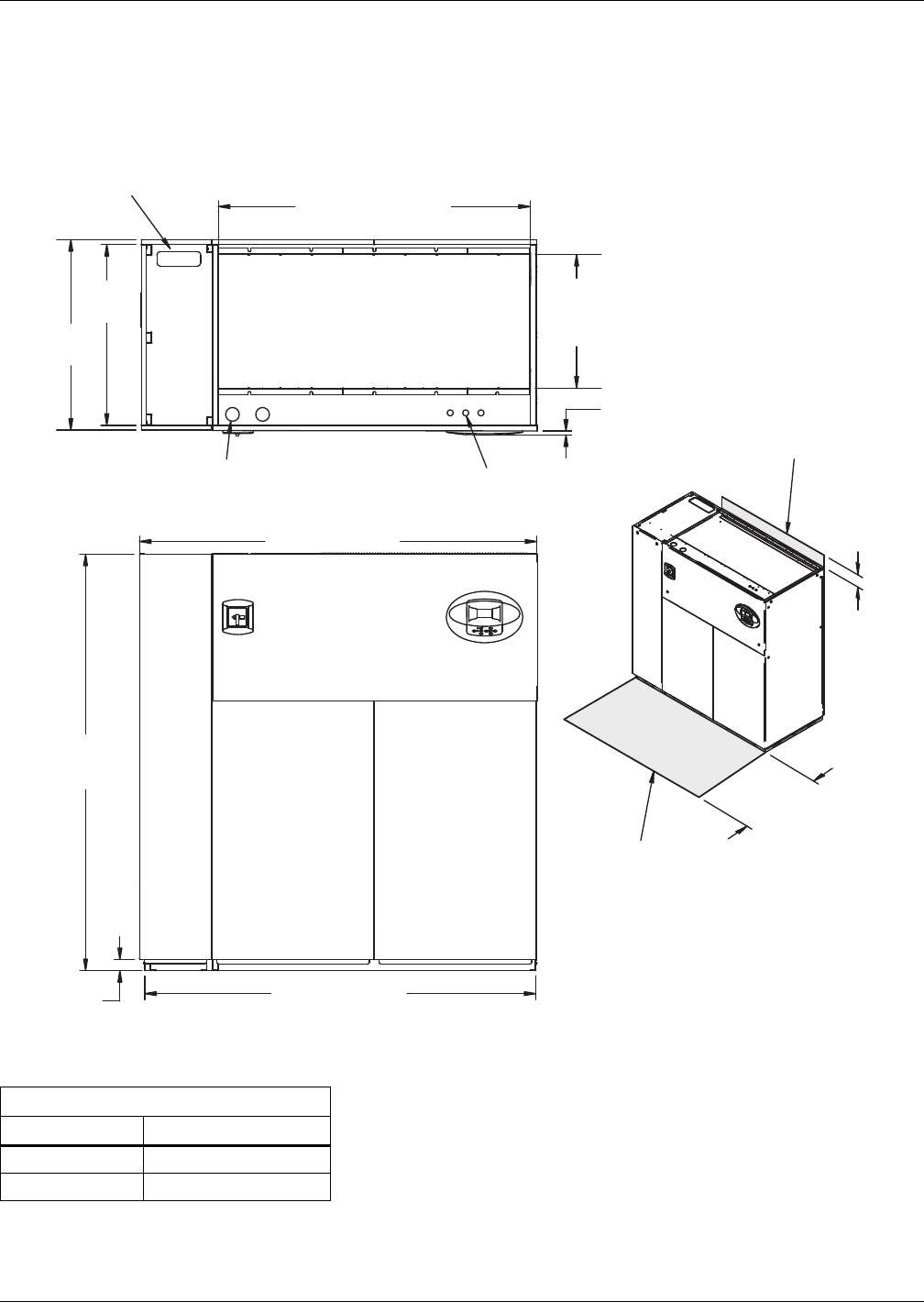
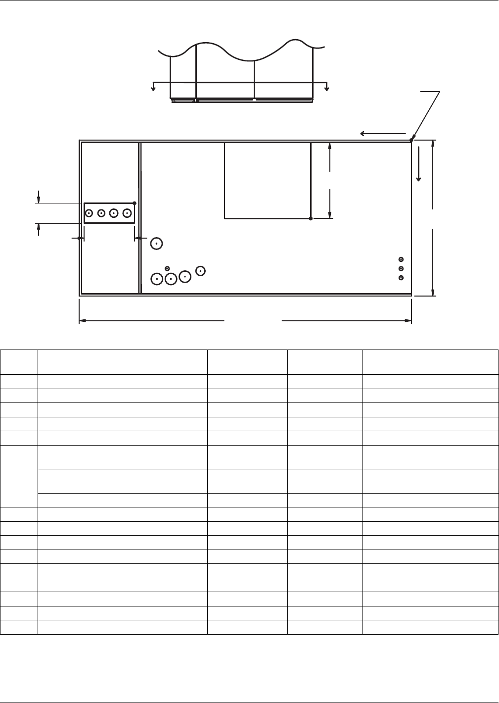
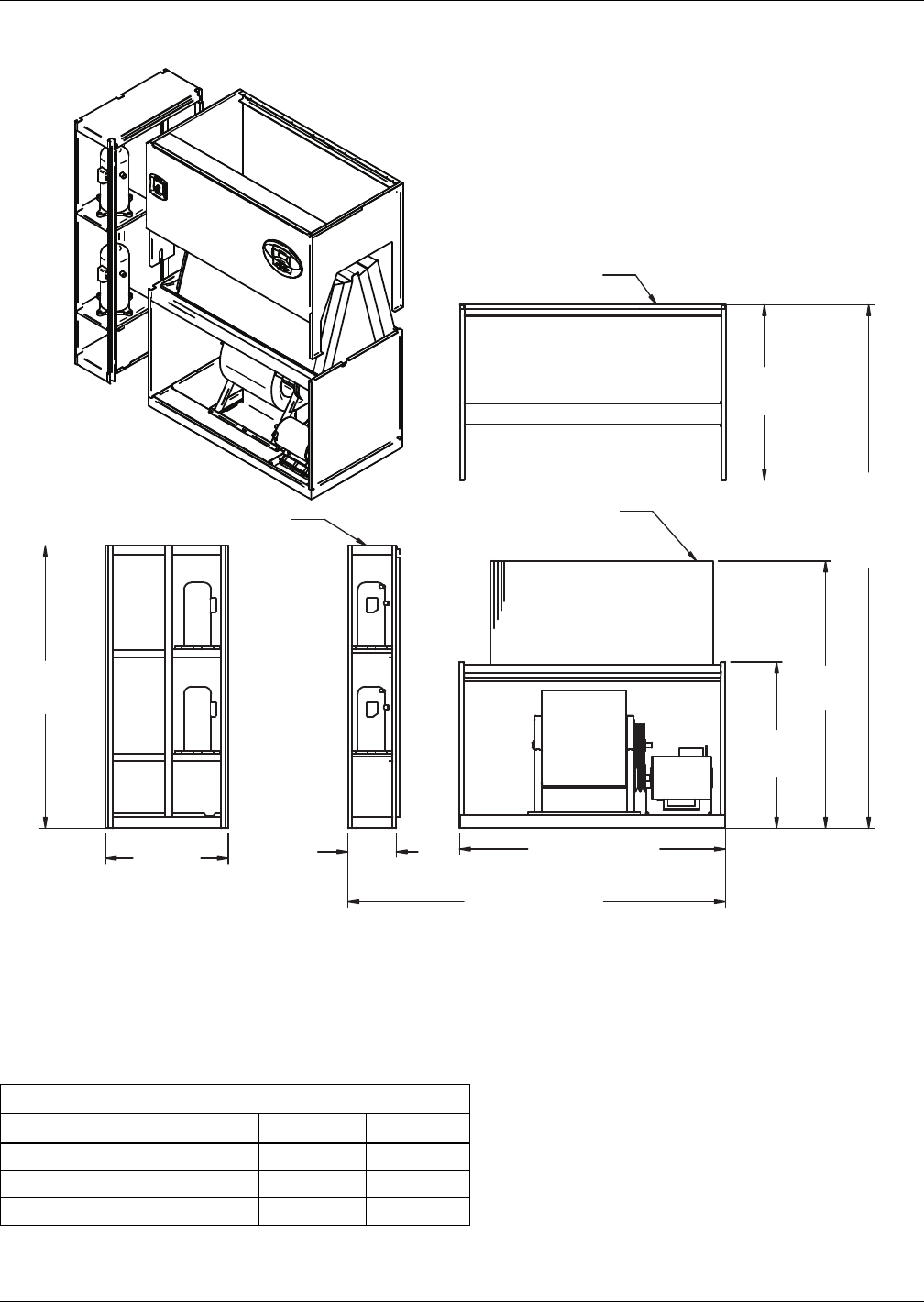
3.5 DIMENSIONS—LIEBERT DS 028-042, DOWNFLOW, AIR-COOLED MODELS
The following figures are general illustrations that show the dimensional layout for a Liebert DS unit.
Figure 8 Dimensions—downflow, air-cooled, 28-42kW (8-12 ton), scroll or digital scroll compressors
with centrifugal fans
Table 6 Weights—downflow, air-cooled, 28-42kW (8-12 ton), scroll/digital scroll compressors
Dry Weight, Approximate, lb. (kg)
Model Type Model Size: 028-042
Air-Cooled 1470 (668)
Dual-Cool 1620 (736)
Source: DPN000796, Rev. 3
Secondary Refrigerant
Piping Entrance
DPN000796
Rev. 3
Filters are accessible
through top of unit only.
Downflow electrical
connections can be made
from top or bottom of unit.
Shaded area indicates a
recommended minimum
clearance for component
access.
TOP VIEW
Air Inlet Opening
Secondary Entrance
High-Volt Connection(s) Secondary Entrance
Low-Volt Connections
Minimum required
for filter replacement
73" (1854mm)
72" (1829mm)
76"
(1930mm)
35"
(889mm)
56-7/8"
(1445mm)
Opening
Opening
3/4"
(19mm)
24-3/8"
(619mm)
34" (864mm)
33"
(838mm)
5"
(127mm)
Bezels
FRONT VIEW
2"
(51mm)
Air-Cooled Systems
17 Liebert® DS™
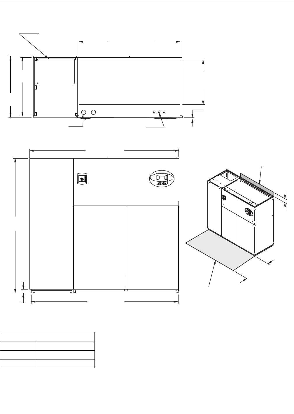
Figure 9 Dimensions—downflow, air-cooled, 28-42kW (8-12 ton), front and/or rear discharge models
Dry Weight, lb (kg) Approximate Dimensions, In. (mm)
Compressor Type Model 028-042 A B
Semi-Hermetic Air-Cooled 1780 (809) 86 (2184mm) 85 (2159)
Dual Cool 1930 (877)
Scroll / Digital Air-Cooled 1470 (668) 73 (1854) 72" (1829)
Dual Cool 1620 (736)
Source: 310697, Pg. 1, Rev. 0
Customer Piping and Wiring Connections
1. For primary connection locations see standard submittals DPN000803, DPN000804 or DPN000900.
A floor stand at least 9" high is recommended if primary connections locations are to be used.
2. If no floor stand is used and unit is placed directly on the floor, then do the following:
a) Use secondary connection locations (shown on standard floor planning submittals).
b) Order a condensate pump.
c) Field pipe condensate and humidier line (if ordered) to secondary connection point in
compressor section.
d) Or order additional SFA's to relocate connection locations
AIR INLET OPENING
Secondary Entrance
High-Voltage Connection(s)
Shaded area indicates a
recommended minimum
clearance for component access.
Secondary Refrigerant
Piping Entrance
Secondary Entrance
Low-Voltage Connections
TOP VIEW
FRONT VIEW
REAR VIEW
310697
Pg. 1, Rev. 0
Air Outlet
Opening Air Outlet
Opening
2"
(51mm)
76"
(1930mm)
56-7/8"
(1445mm) Opening
24-3/8"
(619mm)
Opening
3/4"
(19mm)
Bezels
33"
(838mm)
35"
(889mm)
33-1/2"
(851mm) 33-3/8"
(848mm)
19"
(483mm)
3"
(77mm)
3"
(76mm)
3-1/4"
(81mm)
5"
(127mm)
19"
(483mm)
34"
(864mm)
3-1/4"
(83mm)
Required for Condenser
cleanout on Water/Glycol or
GLYCOOL/Dual Cool
24" (610mm)
Minimum required
for filter replacement
A
B
Filters are accessible
only through top of unit.
Air-Cooled Systems
Liebert® DS™18
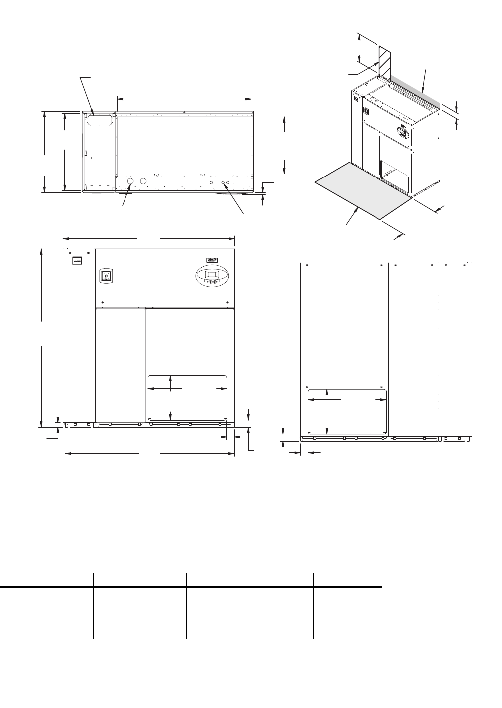
Figure 10 Primary connection locations—downflow, air-cooled, 28-42kW (8-12 ton), scroll or
digital scroll compressors with centrifugal fans
Table 7 Piping data—downflow, air-cooled, 28-42kW (8-12 ton), scroll/digital scroll
Point Description
X
in. (mm)
Y
in. (mm)
Connection Size / Opening
in. (mm)
R Refrigerant Access 59-5/16 (1507) 14-3/4 (375) 11-3/16 x 4 (284 x 102)
L1 Liquid Line System 1 69-15/16 (1776) 16-13/16 (411) 1/2" Cu Sweat
L2 Liquid Line System 2 67-5/8 (1718) 16-13/16 (411) 1/2" Cu Sweat
G1 Hot Gas Discharge 1 65-1/2 (1664) 16-13/16 (411) 5/8" Cu Sweat
G2 Hot Gas Discharge 2 62-7/16 (1586) 16-13/16 (411) 5/8" Cu Sweat
CD
Condensate Drain
(infrared humidifier or no humidifier) * 46 (1168) 29-1/2 (749) 3/4" FPT
Condensate Drain
(steam generating humidifier) * 46 (1168) 29-1/2 (749) 1-1/4" FPT
W/ Optional Pump 46 (1168) 29-1/2 (749) 1/2" Cu Sweat
HUM Humidifier Supply Line 53-1/2 (1359) 29 (737) 1/4" Cu Sweat
ECS Econ-O-Coil Supply 54-7/8 (1394) 22-9/16 (573) 1-5/8" Cu Sweat
ECR Econ-O-Coil Return 49-3/8 (1254) 30-3/4 (781) 1-5/8" Cu Sweat
E1 Electrical Conn. (High Volt) 55-1/2 (1410) 31-1/4 (794) 2-1/2"
E2 Electrical Conn. (High Volt) 52-7/16 (1332) 31-1/4 (794) 2-1/2"
LV1 Electrical Conn. (Low Volt) 2-1/4 (57) 27 (686) 7/8"
LV2 Electrical Conn. (Low Volt) 2-1/4 (57) 29 (737) 7/8"
LV3 Electrical Conn. (Low Volt) 2-1/4 (57) 31 (787) 7/8"
B Blower Outlet 21-15/16 (557) 18-1/16 (459) 18-3/4 x 16-1/16 (476 x 408)
* Field pitch condensate drain line a minimum of 1/8" (3.2 mm) per foot (305 mm). All units contain a factory-installed condensate trap. Do
not trap external to the unit. Drain line may contain boiling water. Select appropriate drain system materials. The drain line must comply
with all local codes.
Piping dimensions shown are connection sizes; field piping sizes may be different depending on distance. Refer to user manual, SL-18825.
Source: DPN000804, Rev. 3
FRONT VIEW
L1 L2 G1 G2
R
ECS
ECR
E1 E2
HUM
CD
B
LV1
O
X
Y
AA
NOTE: Drawing not to scale.
Tolerance on
all piping dimensions
is ± 1/2" (13mm).
4" (102mm)
11-3/16"
(284mm)
BLOWER
OUTLET
All dimensions from
rear corner of unit,
including panels
16-1/16"
(408mm)
35"
(889mm)
73" (1854mm)
LV2
LV3
SECTION A-A
FRONT OF UNIT DPN000804
Rev. 3
Air-Cooled Systems
19 Liebert® DS™
Figure 11 Disassembly dimensions—downflow, air-cooled, 28-42kW (8-12 ton), scroll or digital scroll
compressors with centrifugal fans
Table 8 Component weights—downflow, air-cooled, 28-42kW (8-12 ton), scroll or digital scroll
compressors
Dry Weight, Approximate, lb. (kg)
Component Air-Cooled Dual-Cool
Compressor Assembly 490 (223) 490 (223)
Filter and Electric Box Assembly 210 (96) 210 (96)
Blower and Coil Assembly 770 (350) 920 (418)
Source: DPN000802, Rev. 2
59" (1499mm)
DPN000802
Rev. 2
33"
(838mm)
13"
(330mm)
76"
(1930mm)
72" (1829mm)
Assembled Length
76"
(1930mm)
Assembled
Height
60-3/16"
(1529mm)
37"
(940mm)
39"
(991mm)
Compressor Assembly
Filter & Electric
Box Assembly
Blower & Coil
Assembly
NOTES: Drawing views are simplified with panels removed to show overall dimensions.
See disassembly and handling instructions in installation manual.
Air-Cooled Systems
Liebert® DS™20
Figure 12 Dimensions—downflow, air-cooled, 28-42kW (8-12 ton), semi-hermetic compressors with
centrifugal fans
Table 9 Weights—downflow, air-cooled, 28-42kW (8-12 ton), semi-hermetic compressors
Dry Weight, Approximate, lb. (kg)
Model Type Model Size: 028-042
Air-Cooled 1780 (809)
Dual-Cool 1930 (877)
Source: DPN000795, Rev. 4
DPN000795
Rev. 4
Filters are accessible
through top of unit only.
Downflow electrical
connections can be made
from top or bottom of unit.
Shaded area indicates a
recommended minimum
clearance for component
access.
TOP VIEW
FRONT VIEW
Air Inlet Opening
Secondary Entrance
High Volt Connection(s)
Secondary Refrigerant
Piping Entrance
Secondary Entrance
Low Volt Connections
Minimum required
for filter replacement
86" (2184mm)
85" (2159mm)2"
(51mm)
76"
(1930mm)
35"
(889mm)
56-7/8"
(1445mm)Opening
3/4"
(19mm)
Opening
34"
(864mm)
33"
(838mm)
5"
(127mm)
Bezels
24-3/8"
(619mm)
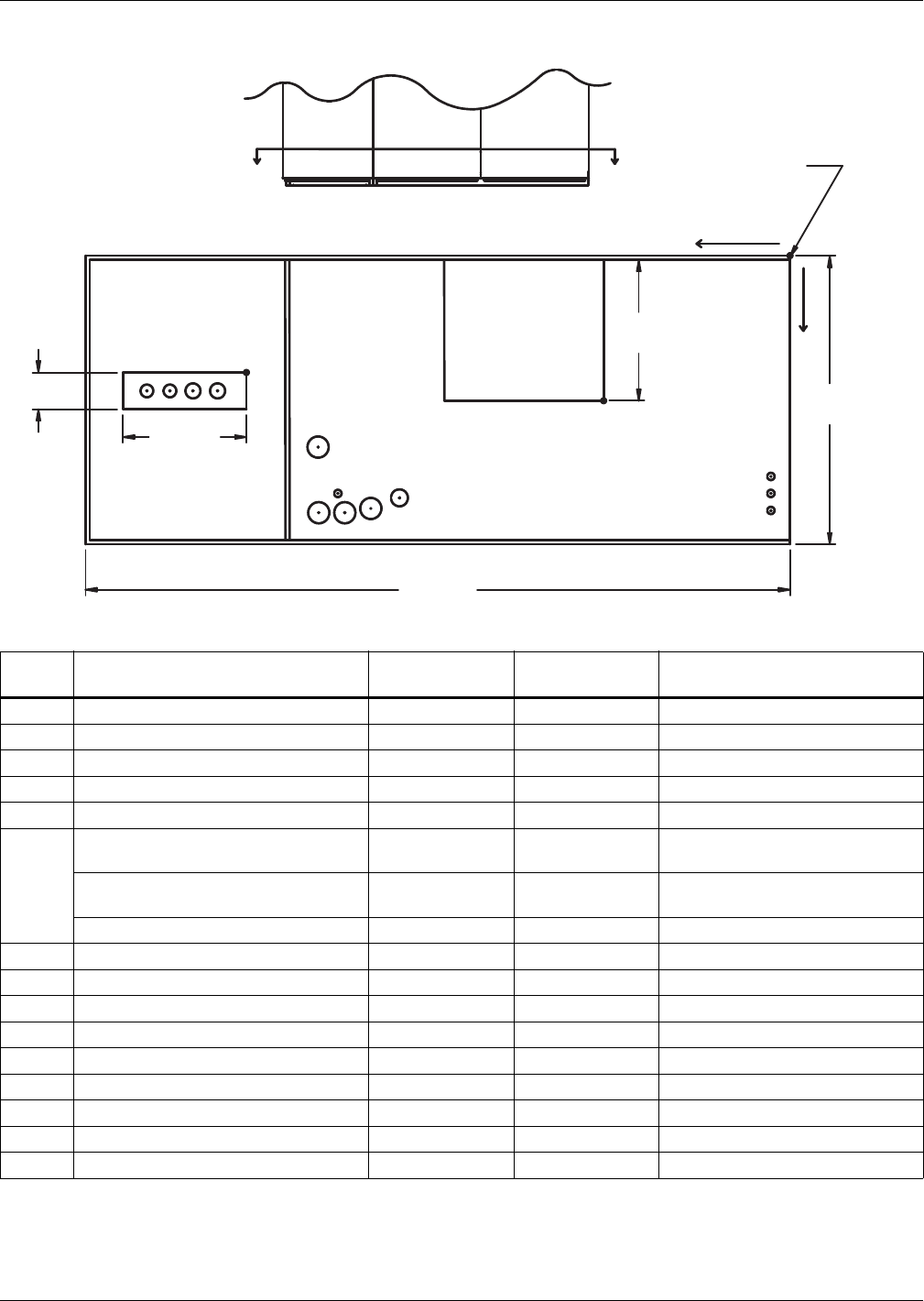
Air-Cooled Systems
21 Liebert® DS™
Figure 13 Primary connection locations—downflow, air-cooled, 28-42kW (8-12 ton), semi-hermetic
compressors with centrifugal fans
Table 10 Piping data—downflow, air-cooled, 28-42kW (8-12 ton), semi-hermetic compressors
Point Description
X
in. (mm)
Y
in. (mm)
Connection Size / Opening
in. (mm)
R Refrigerant Access 63 (1600) 13-13/16 (351) 16-7/16 x 4 (418 x 102)
L1 Liquid Line System 1 79-3/16 (2011) 16-3/4 (425) 1/2" Cu Sweat
L2 Liquid Line System 2 76-1/2 (1943) 16-3/4 (425) 1/2" Cu Sweat
G1 Hot Gas Discharge 1 73-7/8 (1876) 16-3/4 (425) 5/8" Cu Sweat
G2 Hot Gas Discharge 2 70-1/8 (1780) 16-3/4 (425) 5/8" Cu Sweat
CD
Condensate Drain
(infrared humidifier or no humidifier)* 46 (1168) 29-1/2 (749) 3/4" FPT
Condensate Drain
(steam generating humidifier)* 46 (1168) 29-1/2 (749) 1-1/4" FPT
W/ Optional Pump 46 (1168) 29-1/2 (749) 1/2" Cu Sweat
HUM Humidifier Supply Line 53-1/2 (1359) 29 (737) 1/4" Cu Sweat
ECS Econ-O-Coil Supply 54-7/8 (1394) 22-9/16 (573) 1-5/8" Cu Sweat
ECR Econ-O-Coil Return 49-3/8 (1254) 30-3/4 (781) 1-5/8" Cu Sweat
E1 Electrical Conn. (High Volt) 55-1/2 (1410) 31-1/4 (794) 2-1/2"
E2 Electrical Conn. (High Volt) 52-7/16 (1332) 31-1/4 (794) 2-1/2"
LV1 Electrical Conn. (Low Volt) 2-1/4 (57) 27 (686) 7/8"
LV2 Electrical Conn. (Low Volt) 2-1/4 (57) 29 (737) 7/8"
LV3 Electrical Conn. (Low Volt) 2-1/4 (57) 31 (787) 7/8"
B Blower Outlet 21-15/16 (558) 18-1/16 (459) 18-3/4 x 16-1/16 (476 x 408)
* Field pitch condensate drain line a minimum of 1/8" (3.2 mm) per foot (305 mm). All units contain a factory-installed condensate trap. Do
not trap external to the unit. Drain line may contain boiling water. Select appropriate drain system materials. The drain line must comply
with all local codes.
Piping dimensions shown are connection sizes; field piping sizes may be different depending on distance. Refer to user manual, SL-18825.
Source: DPN000803, Rev. 4
L1 L2 G1 G2 R
E1 E2
HUM
B
O
X
Y
AA
ECS
ECR
CD
FRONT VIEW
LV1
NOTE: Drawing not to scale.
Tolerance on
all piping dimensions
is ± 1/2" (13mm).
4" (102mm)
BLOWER
OUTLET
All dimensions from
rear corner of unit
including panels
16-1/16"
(408mm)
35"
(889mm)
LV2
LV3
SECTION A-A
FRONT OF UNIT
16-7/16"
(418mm)
86"
(2184mm)
DPN000803
Rev. 4
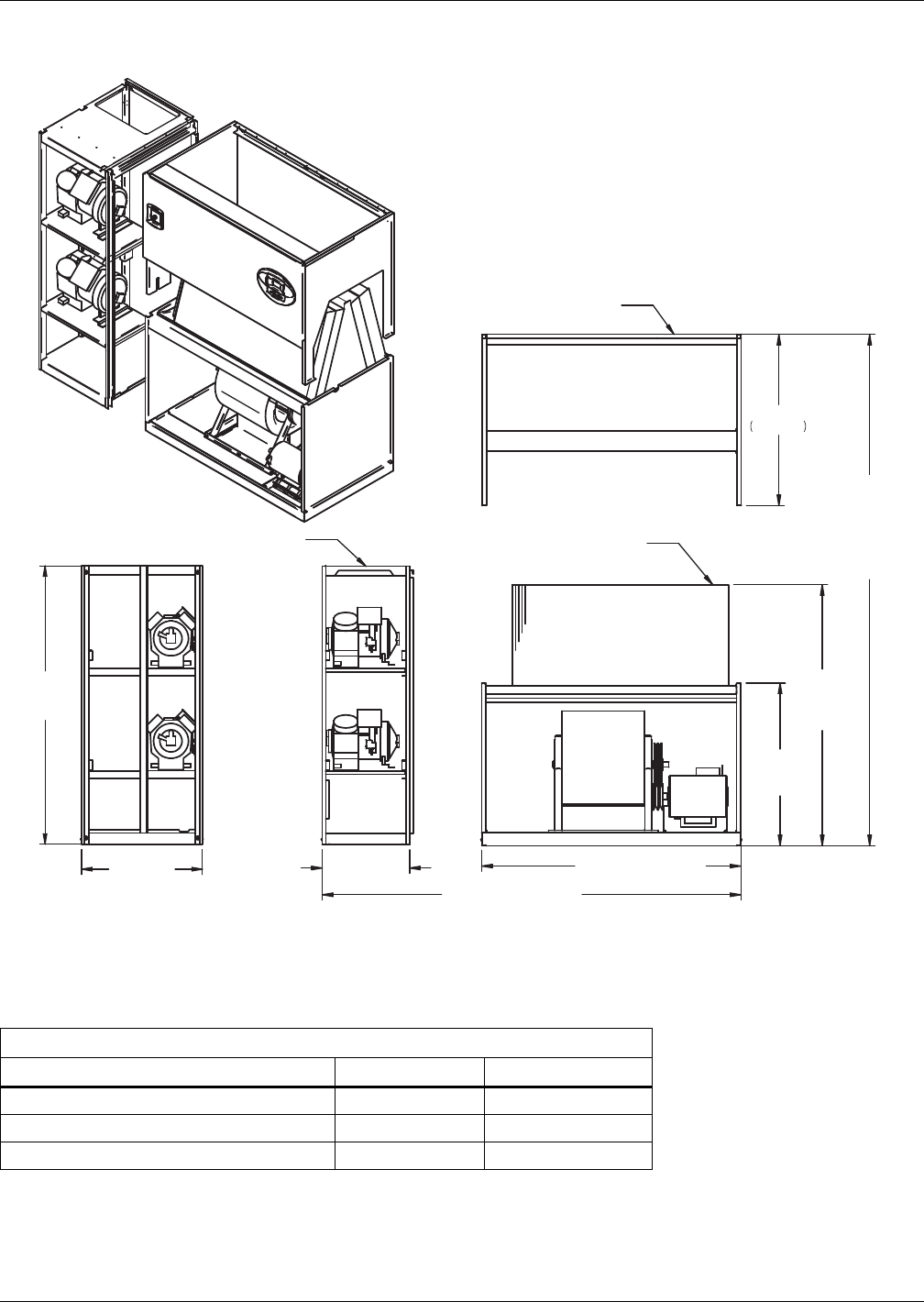
Air-Cooled Systems
Liebert® DS™22
Figure 14 Disassembly dimensions—downflow, air-cooled, 28-42kW (8-12 ton), semi-hermetic
compressors with centrifugal fans
Table 11 Component weights—downflow, air-cooled, 28-42kW (8-12 ton), semi-hermetic compressors
Dry Weight, Approximate, Including Panels, lb (kg)
Component Air-Cooled Dual-Cooled
Compressor Assembly 800 (364) 800 (364)
Filter and Electric Box Assembly 210 (96) 210 (96)
Blower and Coil Assembly 770 (350) 920 (418)
Source: DPN000801, Rev. 2
39"
991mm
59" (1499mm)
DPN000801
Rev. 2
33"
(838mm)
76"
(1930mm)
26"
(660mm) 85" (2159mm)
Assembled Length
76"
(1930mm)
Assembled
Height
60-3/16"
(1529mm)
37"
(940mm)
39"
(991mm)
Compressor Assembly
Filter & Electric
Box Assembly
Blower & Coil
Assembly
NOTES: Drawing views are simplified with panels removed to show overall dimensions.
See disassembly and handling instructions in installation manual.
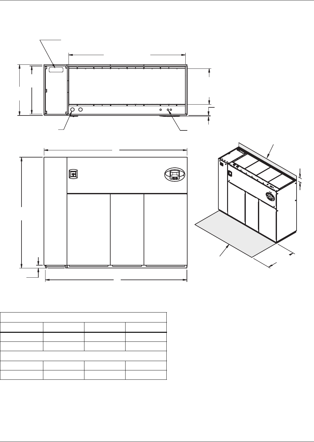
Air-Cooled Systems
23 Liebert® DS™
3.6 DIMENSIONS—LIEBERT DS 053-077, DOWNFLOW, AIR-COOLED MODELS
Figure 15 Dimensions—downflow, air-cooled, 53-77kW (15-22 ton), scroll or digital scroll compressors
with centrifugal fans
Table 12 Weights—downflow, air-cooled, 53-77kW (15-22 ton), scroll or digital scroll compressors
Dry Weight, lb (kg) Approximate
Model No. DS 053 DS 070 DS 077 *
Air Cooled 1920 (871) 1970 (894) 2020 (916)
Dual Cool 2100 (953) 2150 (975) 2200 (998)
Dimensions, in (mm)
Air Cooled “A” 98 (2489) 98 (2489) 98 (2489)
Air Cooled “B” 97 (2464) 97 (2464) 97 (2464)
* Digital scroll compressors not available on DS 077
Source: DPN000925, Rev. 2
33"
(838mm)
35"
(889mm)
A
76"
(1930mm)
2"
(51mm) B
34"
(864mm)
Shaded area indicates a
recommended minimum
clearance for component access.
5"
(127mm)
3/4"
(19mm)
Bezels
24-5/8"
(619mm)
Opening
80"
(2032mm)
Second Refrigerant
Piping Entrance
AIR INLET OPENING
Opening
Secondary Entrance
Low-Volt Connections Minimum required
for filter replacement
Secondary Entrance
High-Volt Connection(s)
TOP VIEW
FRONT VIEW
Notes: Filters are accessible
through top of unit only.
Downflow electrical
connections can be made
from top or bottom of unit.
DPN000925
Rev. 2
Digital scroll compressors
not available on DS 077.
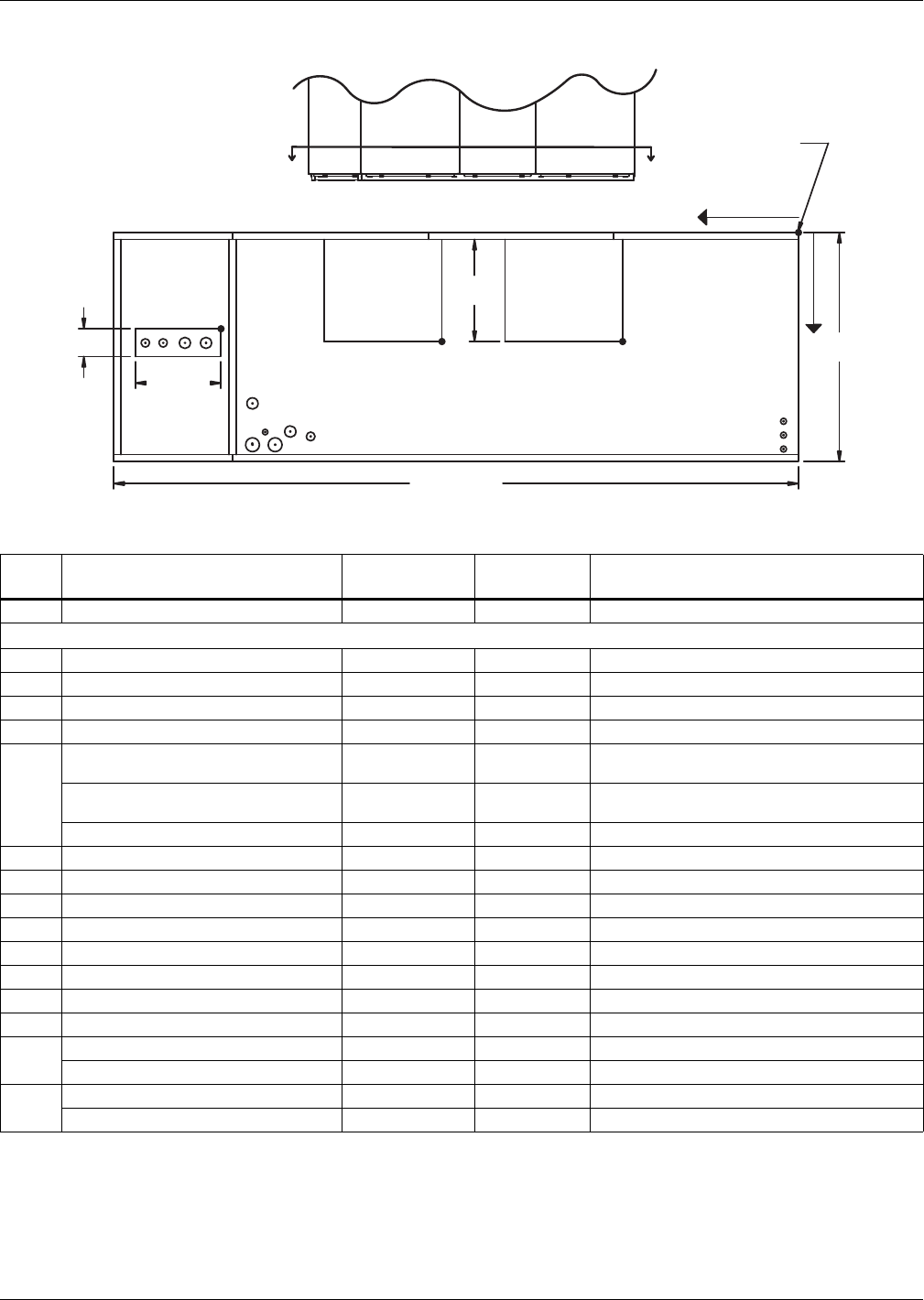
Air-Cooled Systems
Liebert® DS™24
Figure 16 Primary connection locations—downflow, air-cooled, 53-77kW (15-22 ton), scroll or digital
scroll compressors with centrifugal fans
Table 13 Piping data—downflow, air-cooled, 53-77kW (15-22 ton), scroll or digital scroll compressors ***
Point Description
X
in. (mm)
Y
in. (mm)
Connection Size / Opening
in. (mm)
R Refrigerant Access 81-3/4 (2076) 14-3/4 (374) 12-3/16 x 4 (310 x 102)
53kW (15 ton) / 70&77kW (20&22 ton)
L1 Liquid Line System 1 94-11/16 (2405) 16-3/4 (425) 1/2" / 5/8" Cu Sweat
L2 Liquid Line System 2 91-7/8 (2334) 16-3/4 (425) 1/2" / 5/8" Cu Sweat
G1 Hot Gas Discharge 1 88-3/4 (2254) 16-3/8 (416) 7/8" / 1-1/8" Cu Sweat
G2 Hot Gas Discharge 2 85-9/16 (2173) 16-3/8 (416) 7/8" / 1-1/8" Cu Sweat
CD
Condensate Drain
(infrared humidifier or no humidifier)* 67-11/16 (1719) 30-1/2 (775) 3/4" FPT
Condensate Drain
(steam generating humidifier)* 67-11/16 (1719) 30-1/2 (775) 1-1/4" FPT
W/ Optional Pump 67-11/16 (1719) 30-1/2 (775) 1/2" Cu Sweat
HUM Humidifier Supply Line 76-1/2 (1943) 29 (736) 1/4" Cu Sweat
ECS** Econ-O-Coil Supply 78-5/8 (1997) 22-1/4 (565) 2-1/8" Cu Sweat
ECR** Econ-O-Coil Return 72 (1829) 29 (737) 2-1/8" Cu Sweat
E1 Electrical Conn. (High Volt) 78-1/2 (1994) 31-1/8 (790) 2-1/2"
E2 Electrical Conn. (High Volt) 75-3/8 (1915) 31-1/8 (790) 2-1/2"
LV1 Electrical Conn. (Low Volt) 1-7/8 (48) 28-1/2 (724) 7/8"
LV2 Electrical Conn. (Low Volt) 1-7/8 (48) 30-1/4 (768) 7/8"
LV3 Electrical Conn. (Low Volt) 1-7/8 (48) 32 (813) 7/8"
B1 Blower Outlet (15 x 15) 23-1/8 (587) 18-1/16 (459) 18-3/4 x 16-1/16 (476 x 408)
Blower Outlet (15 x 11) 27-3/4 (705) 18-1/16 (459) 14-3/4 x 16-1/16 (375 x 408)
B2 Blower Outlet (15 x 15) 50-3/8 (1280) 18-1/16 (459) 18-3/4 x 16-1/16 (476 x 408)
Blower Outlet (15 x 11) 54-3/8 (1381) 18-1/16 (459) 14-3/4 x 16-1/16 (375 x 408)
* Field pitch condensate drain line a minimum of 1/8" (3.2 mm) per foot (305 mm). All units contain a factory-installed condensate trap. Do
not trap external to the unit. Drain line may contain boiling water. Select appropriate drain system materials. The drain line must comply
with all local codes.
** Supplied on Dual-Cooling systems only (four-pipe system)
*** Digital scroll compressors not available on DS 077.
Piping dimensions shown are connection sizes; field piping sizes may be different depending on distance. Refer to user manual, SL-18825.
Source: DPN000929, Rev 4
AA
L1 L2 G1 G2
R
ECS
ECR
E1 E2
HUM CD
B1
O
X
Y
B2
FRONT VIEW
LV1
NOTE: Drawing not to scale.
Tolerance on
all piping dimensions
is ± 1/2" (13mm).
4"
(102mm)
BLOWER
OUTLET
All dimensions from
rear corner of unit
including panels
16-1/16"
(408mm)
35"
(889mm)
LV2
LV3
SECTION A-A
FRONT OF UNIT
12-3/16"
(310mm)
98" (2489mm)
BLOWER
OUTLET
DPN000929
Rev. 4
Digital scroll compressors
not available on DS 077.
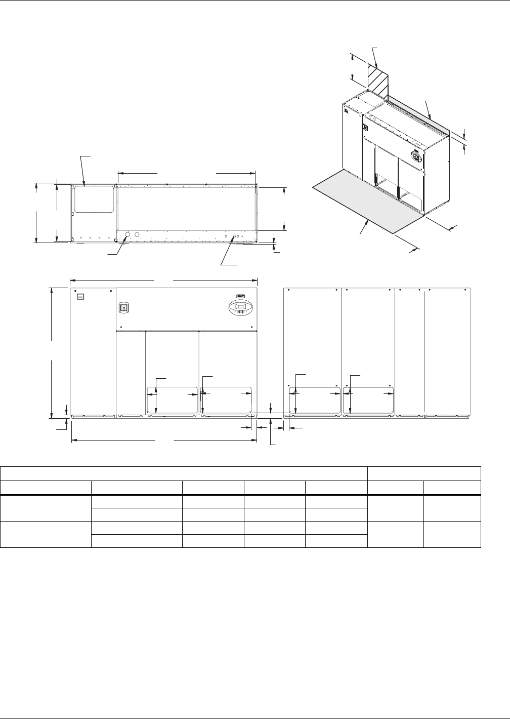
Air-Cooled Systems
25 Liebert® DS™
Figure 17 Dimensions—downflow, air-cooled, 53-77kW (15-22 ton), front and/or rear discharge models
with EC fans
Dry Weight, lb (kg) Approximate Dimensions, in. (mm)
Compressor Type Model 53 70 77 * A B
Semi-Hermetic Air-Cooled 2350 (1069) 2400 (1091) 2450 (1114) 109 (2769) 108 (2743)
Dual Cool 2530 (1150 2580 (1173) 2630 (1196)
Scroll / Digital Air-Cooled 1920 (873) 1970 (896) 2020 (919) 98 (2489) 97 (2464)
Dual Cool 2100 (955) 2150 (978) 2200 (1000)
* Digital scroll compressors not available on 077 models
Source: 310697, Pg. 2, Rev. 0
Customer Piping and Wiring Connections
1. For primary connection locations see standard submittals DPN000928,
DPN000929 or DPN000933.
A floor stand at least 9" high is recommended if primary connections locations are to be used.
2. If no floor stand is used and unit is placed directly on the floor, then do the following:
a) Use secondary connection locations (shown on standard floor planning submittals).
b) Order a condensate pump.
c) Field pipe condensate and humidier line (if ordered) to secondary connection point in
compressor section.
d) Or order additional SFA's to relocate connection locations
AIR INLET OPENING
Secondary Entrance
High-Voltage Connection(s)
Shaded area indicates a
recommended minimum
clearance for component access.
Secondary Refrigerant
Piping Entrance
Secondary Entrance
Low-Voltage Connections
TOP VIEW
FRONT VIEW REAR VIEW
310697
Pg. 2, Rev. 0
Air Outlet
Opening
Air Outlet
Opening
2"
(51mm)
29-1/4"
(743mm)
Air Outlet
Opening
29-1/4"
(743mm)
29-5/8"
(752mm) Air Outlet
Opening
29-5/8"
(752mm)
15-1/8"
(384mm)
15-1/8"
(384mm)
15-1/8"
(384mm)
15-1/8"
(384mm)
76"
(1930mm)
25-5/8"
(619mm)
Opening
80" (2032mm)
Opening
3/4"
(19mm)
33"
(838mm)
35"
(889mm)
3-1/8"
(79mm)
5"
(127mm)
34"
(864mm)
3-1/4"
(83mm)
3-1/4"
(83mm)
Required for Condenser
cleanout on Water/Glycol or
GLYCOOL/Dual Cool
24" (610mm) Minimum required
for filter replacement
A
B
Filters are accessible
only through top of unit.
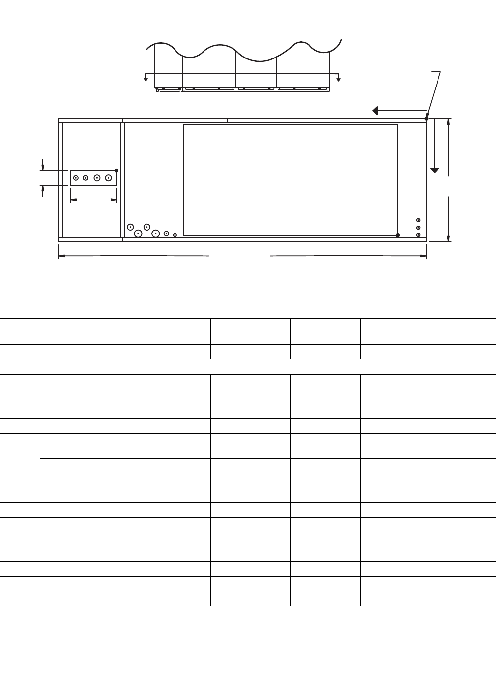
Air-Cooled Systems
Liebert® DS™26
Figure 18 Primary connection locations—downflow air-cooled 53-77kW (15-22 ton), scroll or digital
scroll compressors with EC fans, front, rear or bottom discharge
Table 14 Piping details—downflow air-cooled 53-77kW (15-22 ton) with EC fans, scroll or digital scroll
compressors ***
Point Description
X
in. (mm)
Y
in. (mm)
Connection Size / Opening
in. (mm)
R Refrigerant Access 81-3/4 (2076) 14-3/4 (374) 12-3/16x4 (310x102)
53kW (15 ton)/ 70 & 77kW (20 & 22 ton)
L1 Liquid Line System 1 94-11/16 (2405) 16-3/4 (425) 1/2 / 5/8 Cu Sweat
L2 Liquid Line System 2 91-7/8 (2334) 16-3/4 (425) 1/2 / 5/8 Cu Sweat
G1 Hot Gas Discharge 1 88-3/4 (2254) 16-3/8 (416) 7/8 / 1-1/8 Cu Sweat
G2 Hot Gas Discharge 2 85-9/16 (2173) 16-3/8 (416) 7/8 / 1-1/8 Cu Sweat
CD
Condensate Drain
(Infrared Humidifier or No Humidifier)* 68-3/8 (1737) 31-3/8 (797) 3/4 FPT
W/ Optional Pump 68-3/8 (1737) 31-3/8 (797) 1/2 Cu Sweat
HUM Humidifier Supply Line 76-1/2 (1943) 29 (736) 1/4 Cu Sweat
ECS** Econ-O-Coil Supply (DS Only) 78-5/8 (1997) 22-1/4 (565) 2-1/8 Cu Sweat
ECR** Econ-O-Coil Return (DS Only) 73-15/16 (1862) 26-9/16 (675) 2-1/8 Cu Sweat
E1 Electrical Conn. (High Volt) 78-1/2 (1994) 31-1/8 (790) 2-1/2
E2 Electrical Conn. (High Volt) 75-3/8 (1915) 31-1/8 (790) 2-1/2
LV1 Electrical Conn. (Low Volt) 2 (51) 29 (737) 7/8
LV2 Electrical Conn. (Low Volt) 2 (51) 30-7/8 (784) 7/8
LV3 Electrical Conn. (Low Volt) 2 (51) 32 (813) 7/8
B1 Blower Outlet 4-1/2 (114) 33 (838) 58-3/8x30 (1483x762)
* Field pitch condensate drain line a minimum of 1/8" (3.2 mm) per foot (305 mm). All units contain a factory-installed condensate trap. Do
not trap external to the unit. Drain line may contain boiling water. Select appropriate drain system materials. The drain line must comply
with all local codes.
** Supplied on Dual-Cooling systems only (four-pipe system)
*** Digital scroll compressors not available on DS 077
Piping dimensions shown are connection sizes; field piping sizes may be different depending on distance. Refer to user manual, SL-18825.
Source: DPN002182, Rev. 1
12-3/16"
(310mm)
FRONT OF UNIT
FRONT VIEW
DPN002182
Rev. 1
SECTION A-A
NOTE: Drawing not to scale.
Tolerance on
all piping dimensions
is ± 1/2" (13mm).
ECS ECR
E1 E2
CD
R
LV1
LV2
LV3
X
AA
Y
O
All dimensions from
rear corner of unit
including panels
35"
(889mm)
BLOWER
OUTLET
HUM
L1 L2 G1 G2
B1
4" (102mm)
98" (2489mm)
Digital scroll compressors not
available on 077 models.
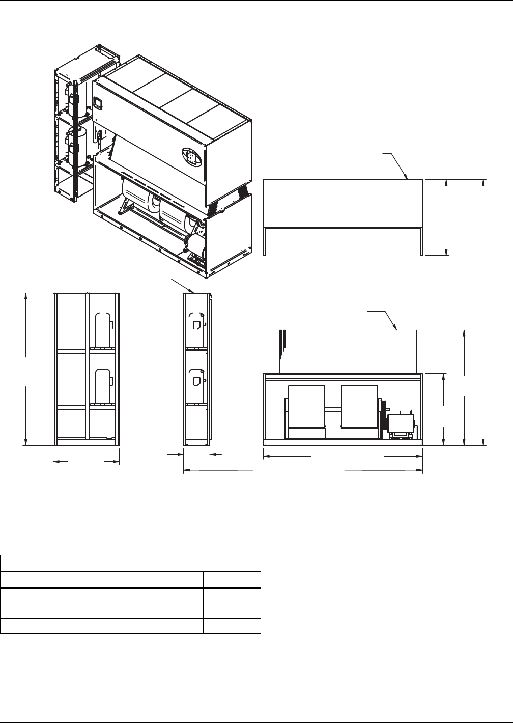
Air-Cooled Systems
27 Liebert® DS™
Figure 19 Disassembly dimensions—downflow, air-cooled, 53-77kW (15-22 ton), scroll or digital scroll
compressors
Table 15 Component weights—downflow, air-cooled, 53-77kW (15-22 ton), scroll or digital scroll
compressors *
Dry Weight, Approximate, Including Panels, lb (kg)
Component Air-Cooled Dual-Cool
Compressor Assembly 540 (246) 540 (246)
Filter and Electric Box Assembly 250 (114) 250 (114)
Blower and Coil Assembly 1230 (560) 1410 (641)
* Digital scroll compressors not available on DS 077
Source: DPN00927, Rev. 4
82" (2083mm)
DPN000927
Rev. 4
33"
(838mm)
DS053-DS077 =
15" (381mm)
DA080,DA085 =
17" (432mm)
76"
(1930mm)
Assembled Length
97" (2464mm)
76"
(1930mm)
Assembled
Height
59-7/16"
(1509mm)
37"
(940mm)
39"
(991mm)
Compressor Assembly
Filter & Electric
Box Assembly
Blower & Coil
Assembly
NOTES: Drawing views are simplified with panels removed to show overall dimensions.
See disassembly and handling instructions in installation manual.
Forward curved
blowers shown.
DA units only
available with EC
blowers, optional
on DS units.
Digital scroll compressors
not available on DS 077.
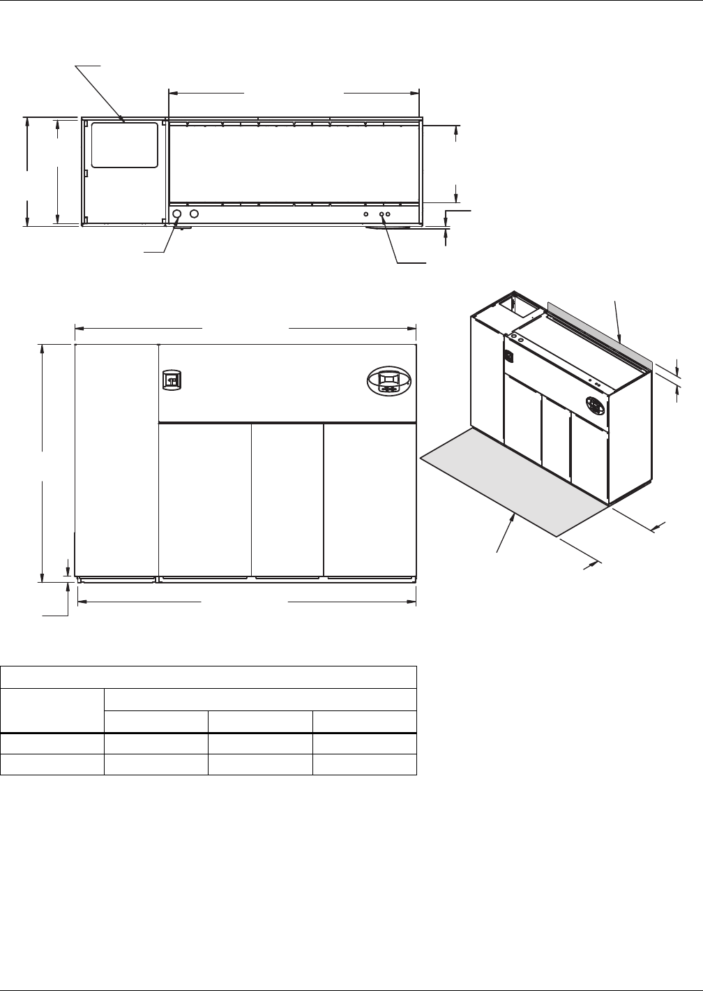
Air-Cooled Systems
Liebert® DS™28
Figure 20 Dimensions—downflow, air-cooled, 53-77kW (15-22 ton) with centrifugal fans, semi-hermetic
compressors with centrifugal fans
Table 16 Weights—downflow, air-cooled, 53-77kW (15-22 ton), semi-hermetic compressors
Dry Weight, Approximate, lb. (kg)
Model Type
Model Size
053 070 077
Air-Cooled 2350 (1069) 2400 (1091) 2450 (1114)
Dual-Cool 2530 (1150) 2580 (1173) 2630 (1196)
Source: DPN000924, Rev. 3
33"
(838mm)
35"
(889mm)
109" (2769mm)
76"
(1930mm)
2"
(51mm)
108" (2743mm)
34"
(864mm)
Shaded area indicates a
recommended minimum
clearance be provided for
component access.
5"
(125mm)
3/4"
(19mm)
24-5/8"
(625mm)
Opening
80"
(2032mm)
Second Refrigerant
Piping Entrance
AIR INLET OPENING
Opening
Bezels
Secondary Entrance
Low-Volt Connections Minimum required
for filter replacement
Secondary Entrance
High-Volt Connection(s)
TOP VIEW
FRONT VIEW
Notes: Filters are accessible
through top of unit only.
Downflow electrical
connections can be made
from top or bottom of unit.
DPN000924
Rev. 3
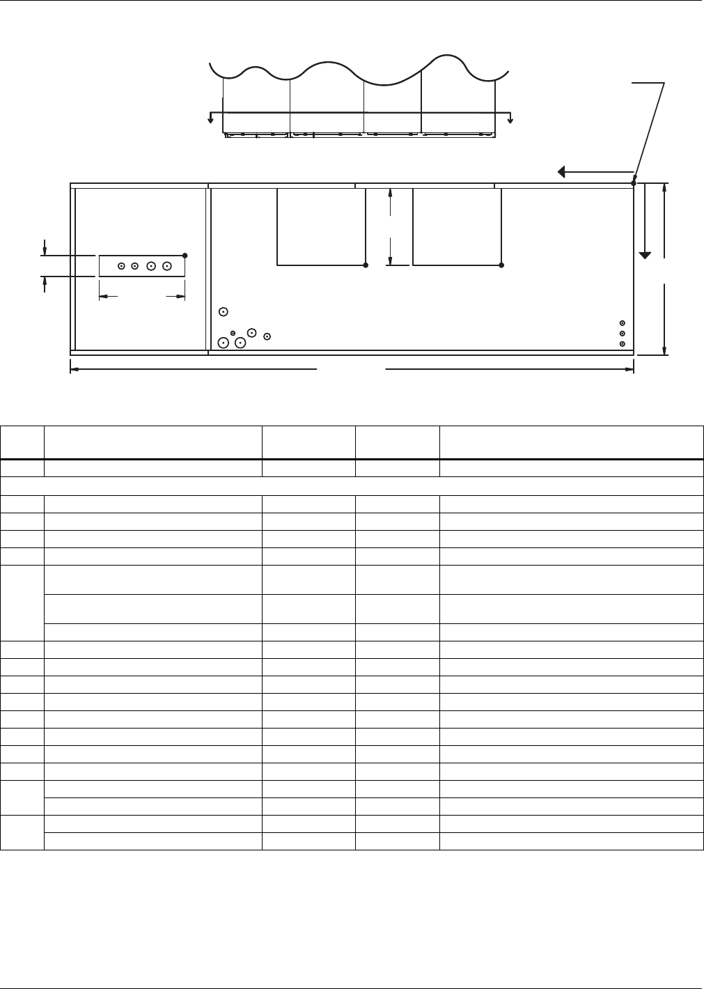
Air-Cooled Systems
29 Liebert® DS™
Figure 21 Primary connection locations—downflow, air-cooled, 53-77kW (15-22 ton), semi-hermetic
compressors with centrifugal fans
Table 17 Piping data—downflow, air-cooled, 53-77kW (15-22 ton), semi-hermetic compressors
Point Description
X
in. (mm)
Y
in. (mm)
Connection Size / Opening
in. (mm)
R Refrigerant Access 82-3/4 (2102) 13-7/8 (352) 16-7/16 x 4 (418 x 102)
53kW (15 tons) / 70 & 77kW (20 & 22 tons)
L1 Liquid Line System 1 97 (2464) 16-7/8 (428) 1/2" / 5/8" Cu Sweat
L2 Liquid Line System 2 93-5/16 (2370) 16-7/8 (428) 1/2" / 5/8" Cu Sweat
G1 Hot Gas Discharge 1 90-5/8 (2302) 16-5/8 (422) 7/8" / 1-1/8" Cu Sweat
G2 Hot Gas Discharge 2 88 (2235) 16-5/8 (422) 7/8" / 1-1/8" Cu Sweat
CD
Condensate Drain
(infrared humidifier or no humidifier) * 67-11/16 (1719) 30-1/2 (775) 3/4" FPT
Condensate Drain
(steam generating humidifier)* 67-11/16 (1719) 30-1/2 (775) 1-1/4" FPT
W/ Optional Pump 67-11/16 (1719) 30-1/2 (775) 1/2" Cu Sweat
HUM Humidifier Supply Line 76-1/2 (1943) 29 (736) 1/4" Cu Sweat
ECS** Econ-O-Coil Supply 78-5/8 (1997) 22-1/4 (565) 2-1/8" Cu Sweat
ECR** Econ-O-Coil Return 72 (1829) 29 (737) 2-1/8" Cu Sweat
E1 Electrical Conn. (High Volt) 78-1/2 (1994) 31-1/8 (790) 2-1/2"
E2 Electrical Conn. (High Volt) 75-3/8 (1915) 31-1/8 (790) 2-1/2"
LV1 Electrical Conn. (Low Volt) 1-7/8 (48) 28-1/2 (724) 7/8"
LV2 Electrical Conn. (Low Volt) 1-7/8 (48) 30-1/4 (768) 7/8"
LV3 Electrical Conn. (Low Volt) 1-7/8 (48) 32 (813) 7/8"
B1 Blower Outlet (15 x 15) 23-1/8 (587) 18-1/16 (459) 18-3/4 x 16-1/16 (476 x 408)
Blower Outlet (15 x 11) 27-3/4 (705) 18-1/16 (459) 14-3/4 x 16-1/16 (375 x 408)
B2 Blower Outlet (15 x 15) 50-3/8 (1280) 18-1/16 (459) 18-3/4 x 16-1/16 (476 x 408)
Blower Outlet (15 x 11) 54-3/8 (1381) 18-1/16 (459) 14-3/4 x 16-1/16 (375 x 408)
* Field pitch condensate drain line a minimum of 1/8" (3.2 mm) per foot (305 mm). All units contain a factory-installed condensate trap. Do
not trap external to the unit. Drain line may contain boiling water. Select appropriate drain system materials. The drain line must comply
with all local codes.
** Supplied on Dual-Cooling Systems only (four-pipe system)
Piping dimensions shown are connection sizes; field piping sizes may be different depending on distance. Refer to user manual, SL-18825.
Source: DPN000928, Rev. 4
L1 L2 G1 G2
R
B1
O
X
Y
B2
ECS
ECR
E1 E2
HUM CD
FRONT VIEW
LV1
NOTE: Drawing not to scale.
Tolerance on
all piping dimensions
is ± 1/2" (13mm).
BLOWER
OUTLET
All dimensions from
rear corner of unit
including panels
LV2
LV3
SECTION A-A
FRONT OF UNIT
AA
BLOWER
OUTLET
16-1/16"
(408mm)
16-7/16"
(418mm)
4" (102mm)
109" (2769mm)
35"
(889mm)
DPN000928
Rev. 4
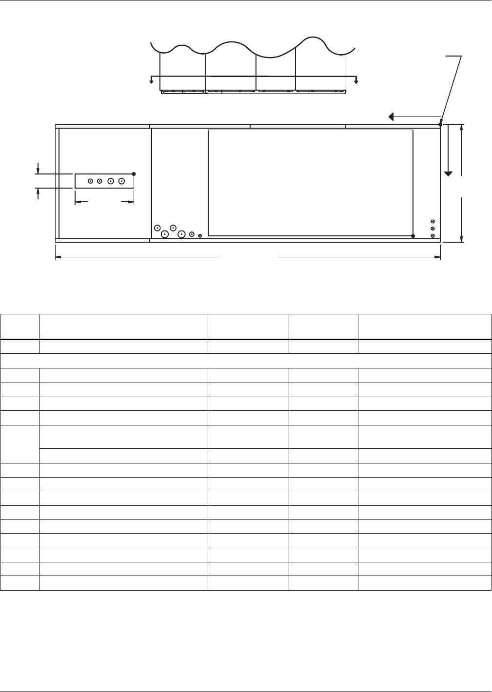
Air-Cooled Systems
Liebert® DS™30
Figure 22 Primary connection locations—downflow, air-cooled 53-77kW (15-22 ton), semi-hermetic
compressors with EC fans, front, rear or bottom discharge
Table 18 Piping details—downflow, air-cooled 53-77kW (15-22 ton) with EC fans, semi-hermetic
compressors
Point Description
X
in. (mm)
Y
in. (mm)
Connection Size / Opening
in. (mm)
R Refrigerant Access 82-3/4 (2102) 13-7/8 (352) 16-7/16 x 4 (4181x102)
53kW (15 ton) /70 & 77kw (20 & 22 ton)
L1 Liquid Line System 1 97 (2464) 16-7/8 (428) 1/2 / 5/8 Cu Sweat
L2 Liquid Line System 2 93-5/16 (2370) 16-7/8 (428) 1/2 / 5/8 Cu Sweat
G1 Hot Gas Discharge 1 90-5/8 (2302) 16-5/8 (422) 7/8 / 1-1/8 Cu Sweat
G2 Hot Gas Discharge 2 88 (2235) 16-5/8 (422) 7/8 / 1-1/8 Cu Sweat
CD
Condensate Drain
(Infrared Humidifier or No Humidifier)* 68-3/8 (1737) 31-3/8 (797) 3/4 FPT
W/ Optional Pump 68-3/8 (1737) 31-3/8 (797) 1/2 Cu Sweat
HUM Humidifier Supply Line 76-1/2 (1943) 29 (736) 1/4 Cu Sweat
ECS** Econ-O-Coil Supply 78-5/8 (1997) 22-1/4 (565) 2-1/8 Cu Sweat
ECR** Econ-O-Coil Return 73-15/16 (1862) 26-9/16 (675) 2-1/8 Cu Sweat
E1 Electrical Conn. (High Volt) 78-1/2 (1994) 31-1/8 (790) 2-1/2
E2 Electrical Conn. (High Volt) 75-3/8 (1915) 31-1/8 (790) 2-1/2
LV1 Electrical Conn. (Low Volt) 2 (51) 29 (737) 7/8
LV2 Electrical Conn. (Low Volt) 2 (51) 30-7/8 (784) 7/8
LV3 Electrical Conn. (Low Volt) 2 (51) 32 (813) 7/8
B1 Blower Outlet 4-1/2 (114) 33 (838) 58-3/8 x 30 (1483x762)
* Field pitch condensate drain line a minimum of 1/8" (3.2 mm) per foot (305 mm). All units contain a factory-installed condensate trap. Do
not trap external to the unit. Drain line may contain boiling water. Select appropriate drain system materials. The drain line must comply
with all local codes.
** Supplied on Dual-Cooling systems only (four-pipe system)
Piping dimensions shown are connection sizes; field piping sizes may be different depending on distance. Refer to user manual, SL-18825.
Source: DPN002179, Rev. 0
16-7/16"
(418mm)
FRONT OF UNIT
FRONT VIEW
DPN002179
Rev. 0
SECTION A-A
NOTE: Drawing not to scale.
Tolerance on
all piping dimensions
is ± 1/2" (13mm).
ECS ECR
E1
CD
R
LV1
LV2
LV3
X
AA
Y
O
All dimensions from
rear corner of unit
including panels
35"
(889mm)
BLOWER
OUTLET
HUM
L1 L2 G1 G2
B1
4" (102mm)
109" (2769mm)
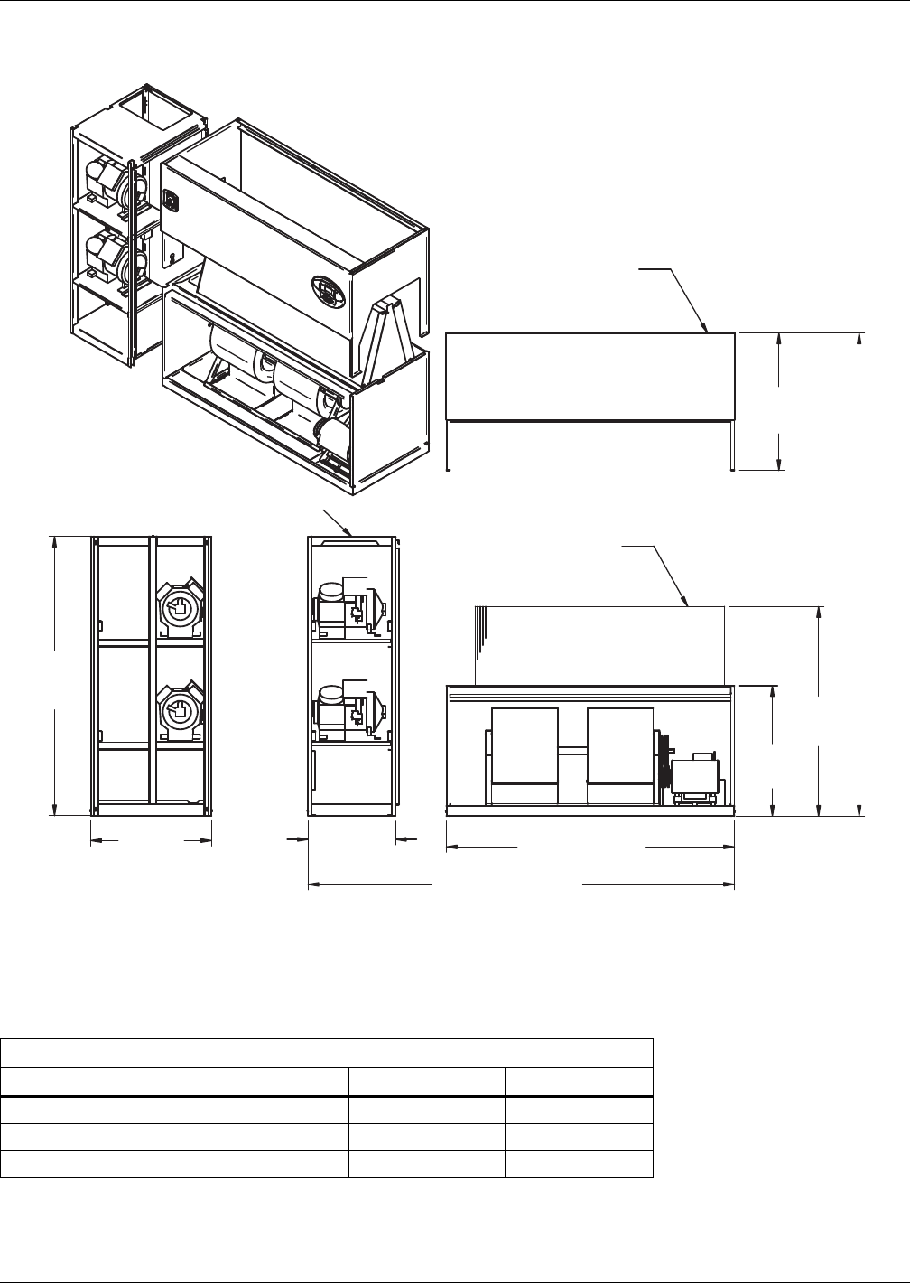
Air-Cooled Systems
31 Liebert® DS™
Figure 23 Disassembly dimensions—downflow, air-cooled, 53-77kW (15-22 ton), semi-hermetic
compressors with centrifugal fans
Table 19 Component weights—downflow, air-cooled, 53-77kW (15-22 ton), semi-hermetic compressors
Dry Weight, Approximate, Including Panels, lb (kg)
Component Air-Cooled Dual-Cool
Compressor Assembly 970 (441) 970 (441)
Filter and Electric Box Assembly 250 (114) 250 (114)
Blower and Coil Assembly 1230 (560) 1410 (641)
Source: DPN000926, Rev. 4
82" (2083mm)
DPN000926
Rev. 4
33"
(838mm)
26"
(660mm)
76"
(1930mm)
108" (2743mm)
Assembled Length
76"
(1930mm)
Assembled
Height
59-7/16"
(1509mm)
37"
(940mm)
39"
(991mm)
Compressor Assembly
Filter & Electric
Box Assembly
Blower & Coil
Assembly
NOTES: Drawing views are simplified with panels removed to show overall dimensions.
See disassembly and handling instructions in installation manual.
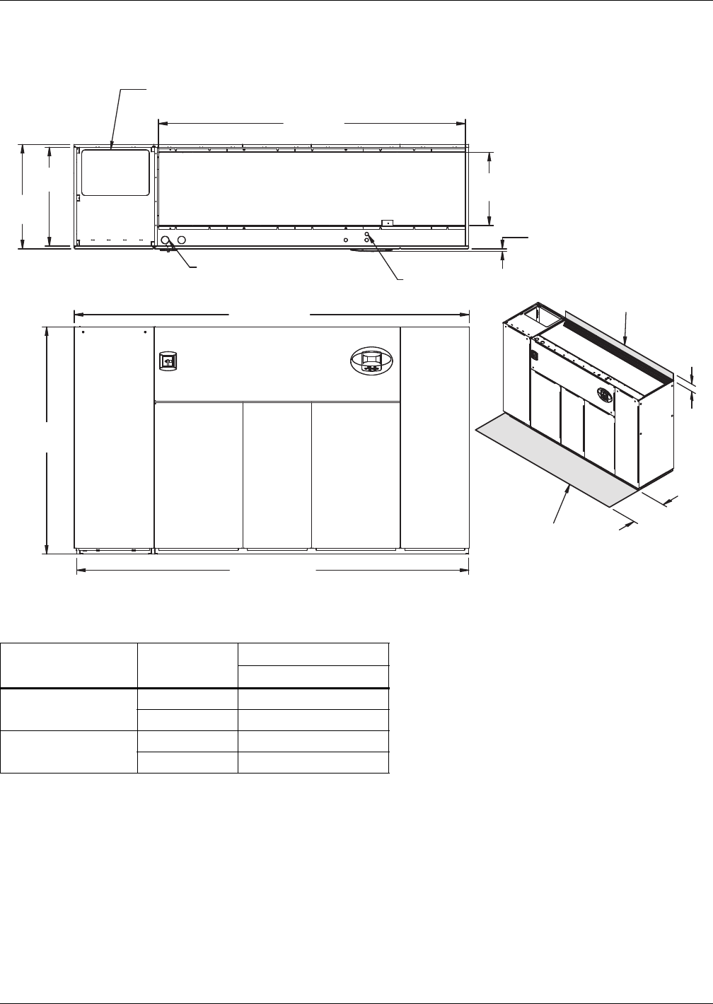
Air-Cooled Systems
Liebert® DS™32
3.7 DIMENSIONS—LIEBERT DS 105, DOWNFLOW, AIR-COOLED MODELS
Figure 24 Dimensions—downflow, air-cooled, 105kW (30 ton), standard scroll and semi-hermetic
compressors with centrifugal fans
Table 20 Weights—downflow, air-cooled, 105kW (30 ton), standard scroll and semi-hermetic
compressors
Compressor Type Cooling Type
Forward-Curved Fans
Weight, lb. (kg)
Semi-Hermetic
Compressors
Air-Cooled 3040 (1382)
Dual-Cool 3400 (1545)
Scroll Compressors * Air-Cooled 2920 (1327)
Dual-Cool 3280 (1491)
* Digital scroll compressors not available on DS 105
Source: DPN001012, Rev. 4
5"
(127mm)
Notes: Filters are accessible
through top of unit only.
Downflow electrical
connections can be made
from top or bottom of unit.
TOP VIEW
AIR INLET OPENING
Shaded area indicates a
recommended minimum
clearance be provided for
component access.
24-3/8"
(619mm)Opening
3/4"
(19mm)
Bezels
Secondary Entrance
High-Volt Connection(s)
76"
(1930mm)
FRONT VIEW
DPN0001012
Rev. 4
34" (864mm)
131" (3327mm)
132" (3353mm)
35"
(889mm)
Secondary Refrigerant
Piping Entrance
Secondary Entrance
Low-Volt Connections
102-13/16"
(2611mm) Opening
33"
(838mm)
Minimum required
for filter replacement
Digital scroll
compressors not
available on DS 105.
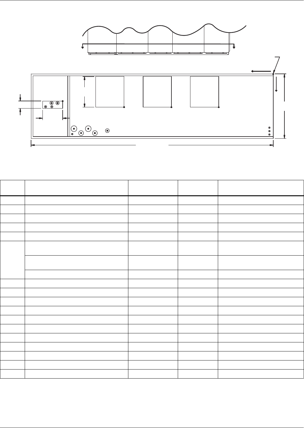
Air-Cooled Systems
33 Liebert® DS™
Figure 25 Primary connection locations—downflow, air-cooled, 105kW (30 ton), standard scroll and
semi-hermetic compressors with centrifugal fans
Table 21 Piping data—downflow, air-cooled, 105kW (30 ton), standard scroll*** and semi-hermetic
compressors
Point Description
X
in. (mm)
Y
in. (mm)
Connection Size / Opening
in. (mm)
R Refrigerant Access 109 (2769) 15-3/4 (400) 16-7/16 x 4 (418 x 102)
L1 Liquid Line System 1 121-3/4 (3092) 16-3/4 (425) 5/8" Cu Sweat
L2 Liquid Line System 2 118-1/8 (3000) 16-3/4 (425) 5/8" Cu Sweat
G1 Hot Gas Discharge 1 118-1/4 (3004) 14-1/4 (362) 1-1/8" Cu Sweat
G2 Hot Gas Discharge 2 115-5/8 (2937) 14-1/4 (362) 1-1/8" Cu Sweat
CD
Condensate Drain
(infrared humidifier or no humidifier)* 83-13/16 (2129) 30 (762) 3/4" FPT
Condensate Drain
(steam generating humidifier)* 83-13/16 (2129) 30 (762) 1-1/4" FPT
W/ Optional Pump 83-13/16 (2129) 30 (762) 1/2" Cu Sweat
HUM Humidifier Supply Line 102-3/4 (2610) 31-3/4 (806) 1/4" Cu Sweat
ECS** Econ-O-Coil Supply 101-7/8 (2588) 29 (737) 2-5/8" Cu Sweat
ECR** Econ-O-Coil Return 94-9/16 (2402) 29 (737) 2-5/8" Cu Sweat
E1 Electrical Conn. (High Volt) 98-1/8 (2492) 31-1/4 (794) 2-1/2"
E2 Electrical Conn. (High Volt) 91 (2311) 31-1/4 (794) 2-1/2"
LV1 Electrical Conn. (Low Volt) 2 (51) 28-1/4 (718) 7/8"
LV2 Electrical Conn. (Low Volt) 2 (51) 30-1/4 (768) 7/8"
LV3 Electrical Conn. (Low Volt) 2 (51) 32 (813) 7/8"
B1 Blower Outlet 27-7/8 (708) 18 (457) 14-1/2 x 15-11/16 (368 x 398)
B2 Blower Outlet 52-1/16 (1322) 18 (457) 14-1/2 x 15-11/16 (368 x 398)
B3 Blower Outlet 76-1/4 (1937) 18 (457) 14-1/2 x 15-11/16 (368 x 398)
* Field pitch condensate drain line a minimum of 1/8" (3.2 mm) per foot (305 mm). All units contain a factory-installed condensate trap. Do not
trap external to the unit. Drain line may contain boiling water. Select appropriate drain system materials. The drain line must comply with all
local codes.
** Supplied on Dual-Cooling systems only (four-pipe system)
*** Digital scroll compressors not available on DS 105
Piping dimensions shown are connection sizes; field piping sizes may be different depending on distance. Refer to user manual, SL-18825.
Source: DPN001014, Rev. 3
ECS ECR
E1 E2
CD
B1
O
X
Y
AA
B2
B3
HUM
R
L1 L2
G1 G2
FRONT VIEW
LV1
NOTE: Drawing not to scale.
Tolerance on
all piping dimensions
is ± 1/2" (13mm).
4" (102mm)
BLOWER
OUTLET
All dimensions from
rear corner of unit
including panels
35"
(889mm)
LV2
LV3
SECTION A-A
FRONT OF UNIT
16-7/16"
(418mm)
131" (3327mm)
BLOWER
OUTLET
BLOWER
OUTLET
15-11/16"
(398mm)
DPN001014
Rev. 3
Digital scroll compressors not
available on 105 models.
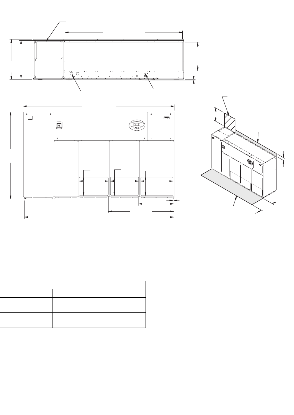
Air-Cooled Systems
Liebert® DS™34
Figure 26 Dimensions—downflow, air-cooled, 105kW (30 ton), front discharge models with EC fans
Dry Weight, lb (kg) Approximate
Compressor Type Model 105
Semi-Hermetic Air-Cooled 2774 (1258)
Dual Cool 3134 (1422)
Scroll Air-Cooled 2654 (1204)
Dual Cool 3014 (1367)
Digital scroll compressors not available on DS 105
Source: 310697, Pg. 3, Rev. 0
Customer Piping and Wiring Connections
1. For primary connection locations see standard submittals DPN001014 or DPN001015.
A floor stand at least 9" high is recommended if primary connections locations are to be used.
2. If no floor stand is used and unit is placed directly on the floor, then do the following:
a) Use secondary connection locations (shown on standard floor planning submittals).
b) Order a condensate pump.
c) Field pipe condensate and humidier line (if ordered) to secondary connection point in
compressor section.
d) Or order additional SFA's to relocate connection locations
Secondary Entrance
High-Voltage Connection(s)
Shaded area indicates a
recommended minimum
clearance for component access.
Secondary Refrigerant
Piping Entrance
Secondary Entrance
Low-Voltage Connections
TOP VIEW
FRONT VIEW
310697
Pg. 3, Rev. 0
Air Outlet
Opening
Air Outlet
Opening
Air Outlet
Opening
3/4"
(19mm)
25-5/8"
(649mm)
24-7/8"
(649mm)
28-1/4"
(718mm)
16-1/8"
(410mm)
16-1/8"
(410mm)
16-1/8"
(410mm)
24-3/8"
(619mm)
Opening
102-7/8" (2611mm)
Opening
132" (3353mm)
30-7/8"
(783mm)
57-1/2"
(1459mm)
131" (3326mm)
3/4"
(19mm)
33"
(838mm)
35"
(889mm)
5"
(127mm)
34"
(864mm)
Required for Condenser
cleanout on Water/Glycol or
GLYCOOL/Dual Cool
Downflow electrical
connections can be made
from top or bottom of unit
24" (610mm) Minimum required
for filter replacement
Filters are accessible
only through top of unit.
AIR INLET OPENING
76"
(1930mm)
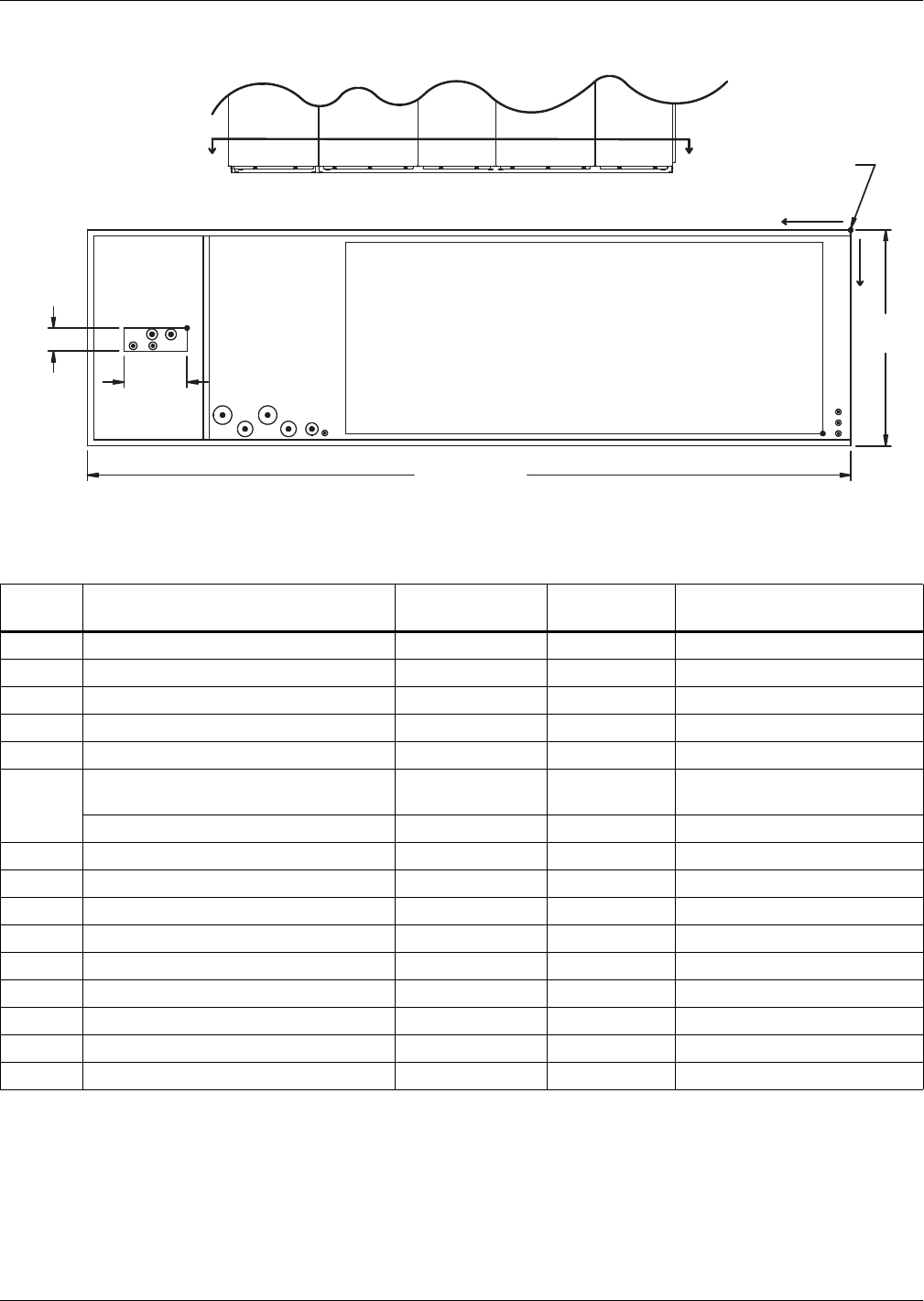
Air-Cooled Systems
35 Liebert® DS™
Figure 27 Primary connection locations—downflow, air-cooled 105kW (30 ton), standard scroll and
semi-hermetic compressors with EC fans, front, rear or bottom discharge
Table 22 Piping data—downflow, air-cooled 105kW (30 ton) with EC fans, standard scroll*** and
semi-hermetic compressors
Point Description
X
in. (mm)
Y
in. (mm)
Connection Size / Opening
in. (mm)
R Refrigerant Access 109 (2769) 15-3/4 (400) 16-7/16 x 4 (418 x 102)
L1 Liquid Line System 1 121-3/4 (3092) 16-3/4 (425) 5/8 Cu Sweat
L2 Liquid Line System 2 118-1/8 (3000) 16-3/4 (425) 5/8 Cu Sweat
G1 Hot Gas Discharge 1 118-1/4 (3004) 14-1/4 (362) 1-1/8 Cu Sweat
G2 Hot Gas Discharge 2 115-5/8 (2937) 14-1/4 (362) 1-1/8 Cu Sweat
CD
Condensate Drain
(Infrared Humidifier or No Humidifier)* 87-3/8 (2220) 31 (787) 3/4 FPT
W/ Optional Pump 83-13/16 (2129) 30 (762) 1/2 Cu Sweat
HUM Humidifier Supply Line 85-5/16 (2167) 32-1/2 (825) 1/4 Cu Sweat
ECS ** Econ-O-Coil Supply 101-7/8 (2588) 29 (737) 2-5/8 Cu Sweat
ECR ** Econ-O-Coil Return 94-9/16 (2402) 29 (737) 2-5/8 Cu Sweat
E1 Electrical Conn. (High Volt) 98-1/8 (2492) 31 (788) 2-1/2
E2 Electrical Conn. (High Volt) 91 (2311) 31 (788) 2-1/2
LV1 Electrical Conn. (Low Volt) 2 (51) 29 (737) 7/8
LV2 Electrical Conn. (Low Volt) 2 (51) 30-7/8 (784) 7/8
LV3 Electrical Conn. (Low Volt) 2 (51) 32 (813) 7/8
B1 Blower Outlet 4-1/2 (114) 33 (838) 77-3/8 x 30 (1965 x 762)
* Field pitch condensate drain line a minimum of 1/8" (3.2 mm) per foot (305 mm). All units contain a factory-installed condensate trap. Do
not trap external to the unit. Drain line may contain boiling water. Select appropriate drain system materials. The drain line must comply
with all local codes.
** Supplied on Dual-Cooling systems only (four-pipe system)
*** Digital scroll compressors not available on DS 105
Piping dimensions shown are connection sizes; field piping sizes may be different depending on distance. Refer to user manual, SL-18825.
Source: DPN002154, Rev. 0
16-7/16"
(418mm)
FRONT OF UNIT
FRONT VIEW DPN002154
Rev. 0
SECTION A-A
NOTE: Drawing not to scale.
Tolerance on
all piping dimensions
is ± 1/2" (13mm).
ECS ECR
E1 E2
CD
LV1
LV2
LV3
X
Y
O
AAAll dimensions from
rear corner of unit
including panels
35"
(889mm)
BLOWER
OUTLET
HUM
L1 L2
G1 G2
B1
R
4" (102mm)
132" (3353mm)
Digital scroll compressors
not available on 105
models.
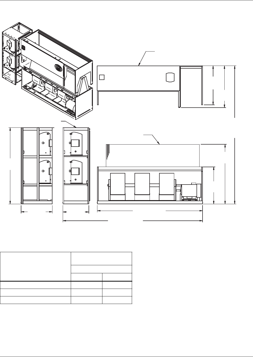
Air-Cooled Systems
Liebert® DS™36
Figure 28 Disassembly dimensions—downflow, air-cooled, 105kW (30 ton), standard scroll compressors
with centrifugal
Table 23 Component weights—downflow, air-cooled, 105kW (30 ton), standard scroll compressors *
Component
Dry Weight, Approximate
Including Panels, lb (kg)
Forward-Curved Fans
Air-Cooled Dual-Cool
Compressor Assembly 830 (377) 830 (377)
Filter and Electric Box Assembly 270 (123) 270 (123)
Blower and Coil Assembly 1820 (827) 2180 (991)
* Digital scroll compressors not available on DS 105
Source: DPN001058, Rev. 2
DPN001058
Rev. 2
NOTES: Drawing views are simplified with panels removed to show overall dimensions.
See disassembly and handling instructions in installation manual.
Filter & Electric Box Assembly
Compressor Assembly
Blower & Coil
Assembly
39"
(991mm)
41-11/16"
(1059mm)
76"
(1930mm)
Assembled Height
59-7/16"
(1510mm)
37"
(940mm)
105" (2667mm)
131" (3327mm)
Assembled Length
76"
(1930mm)
26"
(660mm)
33"
(838mm)
Digital scroll compressors not
available on 105 models.
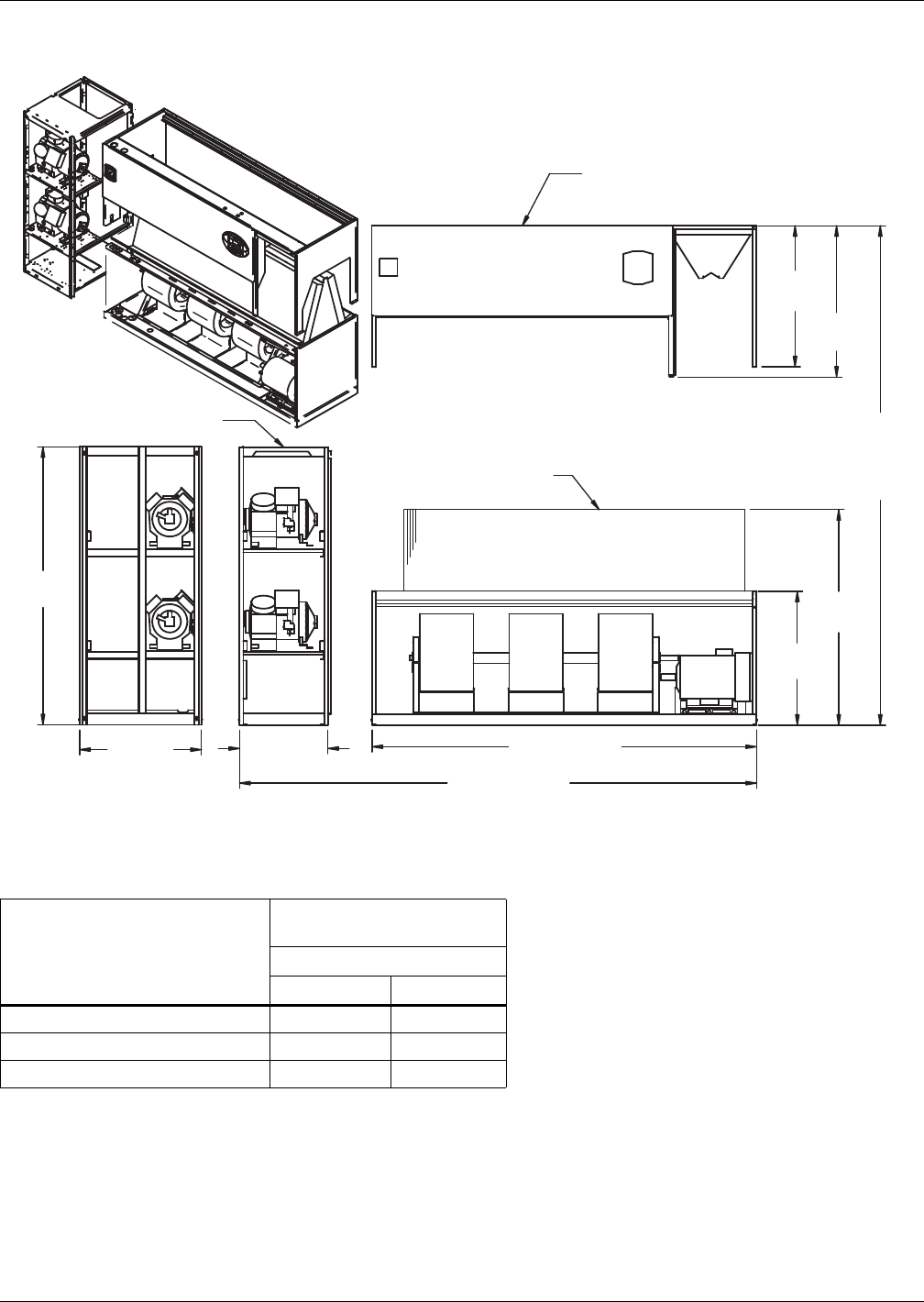
Air-Cooled Systems
37 Liebert® DS™
Figure 29 Disassembly dimensions—downflow, air-cooled, 105kW (30 ton), semi-hermetic compressors
with centrifugal
Table 24 Component weights—downflow, air-cooled, 105kW (30 ton), semi-hermetic compressors
Component
Dry Weight, Approximate,
Including Panels, lb (kg)
Forward-Curved Fans
Air-Cooled Dual-Cool
Compressor Assembly 950 (432) 950 (432)
Filter and Electric Box Assembly 270 (123) 270 (123)
Blower and Coil Assembly 1820 (827) 2180 (991)
Source: DPN001057, Rev. 2
Filter & Electric Box Assembly
Compressor Assembly
Blower & Coil
Assembly
39"
(991mm)
76"
(1930mm)
Assembled
Height
37"
(940mm)
33"
(838mm)
76"
(1930mm)
NOTES: Drawing views are simplified with panels removed to show overall dimensions.
See disassembly and handling instructions in installation manual.
59-7/16”
(1509mm)
26”
(660mm) 105" (2667mm)
131" (3327mm)
Assembled Length
41 11/16"
(1059mm)
DPN001057
Rev. 2
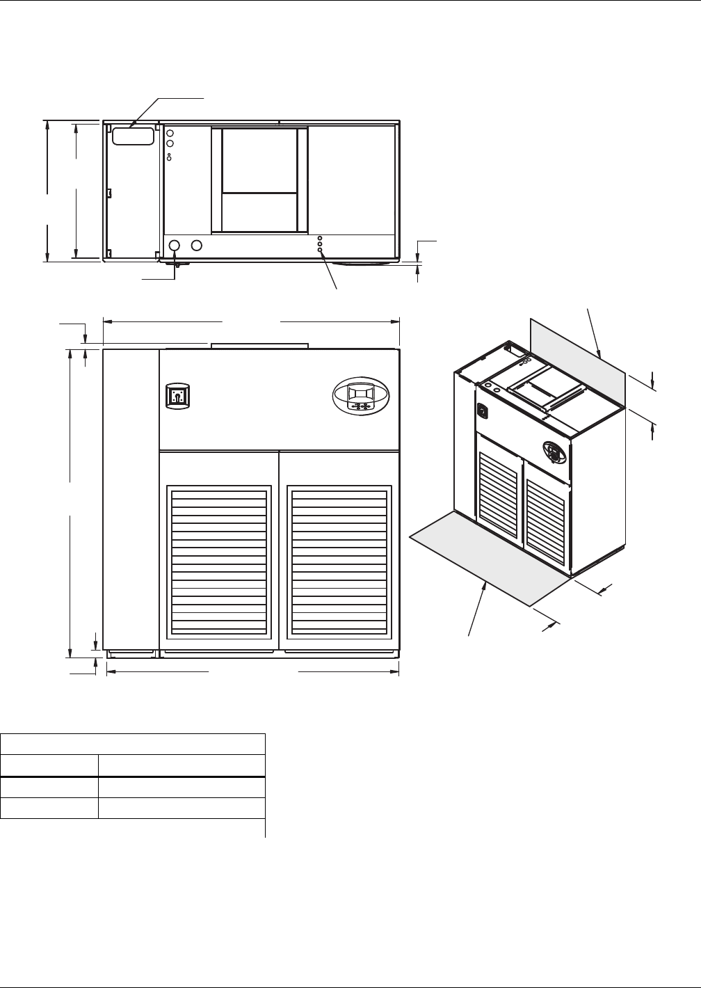
Air-Cooled Systems
Liebert® DS™38
3.8 DIMENSIONS—LIEBERT DS 028-042, UPFLOW, AIR-COOLED MODELS
Figure 30 Dimensions—upflow, air-cooled, 28-42kW (8-12 ton), scroll or digital scroll compressors with
centrifugal fans
Table 25 Weights—upflow, air-cooled, 28-42kW (8-12 ton), scroll or digital scroll compressors
Dry Weight, Approximate, lb. (kg)
Model Type Forward-Curved Fans
Air-Cooled 1520 (689)
Dual-Cool 1670 (758)
Source: DPN001163, Rev. 2
Alternate Refrigerant
Piping Entrance
3/4" (19mm)
Bezels
24"
(610mm)
34"
(864mm)
72" (1829mm)
FRONT VIEW
DPN001163
Rev. 2
Shaded area indicates a
recommended minimum
clearance for component
access.
2"
(51mm)
76"
(1930mm)
1-1/2"
(38mm)
TOP VIEW
73"
(1854mm)
High-Volt Connection(s)
35"
(889mm)
33"
(838mm)
Minimum required
for blower replacement
Low-Volt Connection(s)
Note: Front air return unit shown. For
rear return unit, in addition to front service
area shown, also include 25" (635mm) on
one side of unit for access to rear return
filter box. See DPN001196.
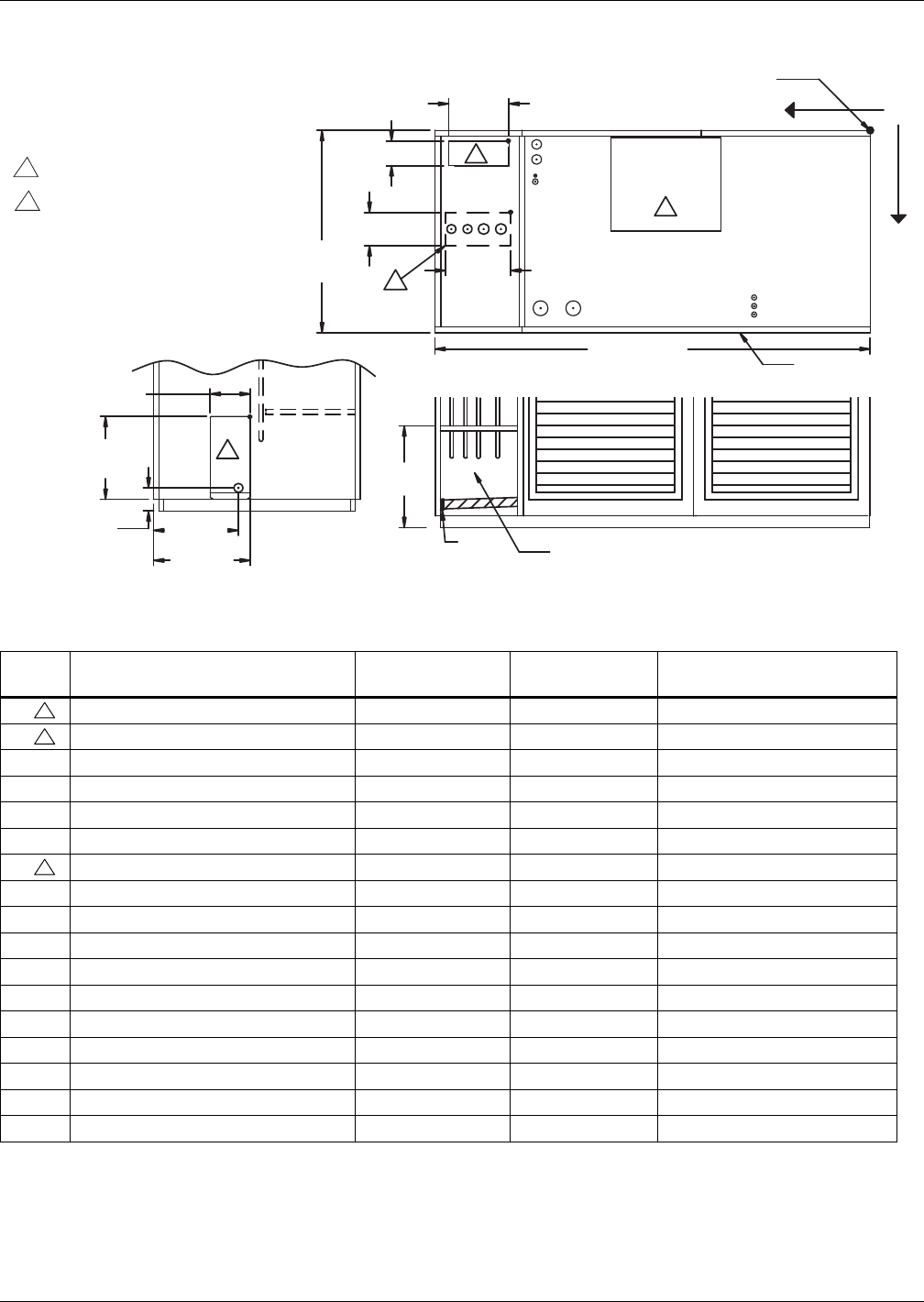
Air-Cooled Systems
39 Liebert® DS™
Figure 31 Primary connection locations—upflow, air-cooled, 28-42kW (8-12 ton), scroll or digital scroll
compressors with centrifugal fans
Table 26 Piping data—upflow, air-cooled, 28-42kW (8-12 ton), scroll or digital scroll compressors
Point Description
X
in. (mm)
Y
in. (mm)
Connection Size / Opening
in. (mm)
R1 Refrigerant Access (Top) 60-1/2 (1537) 1-7/8" (48mm) 10-1/8 x 4-1/8 (257 x 105)
R2 Refrigerant Access (Bottom) 59-3/8" (1508mm) 14-3/4" (375mm) 11-1/8 x 4 (283 x 102)
L1 Liquid Line System 1 70" (1778mm) 16-3/4 (425) 1/2" Cu Sweat
L2 Liquid Line System 2 67-5/8" (1718mm) 16-3/4 (425) 1/2" Cu Sweat
G1 Hot Gas Discharge 1 65-3/8" (1661mm) 16-5/8 (422) 5/8" Cu Sweat
G2 Hot Gas Discharge 2 63" (1600mm) 16-5/8 (422) 5/8" Cu Sweat
R3 Refrigerant Access (Side) — — 6 x 17-3/16 (152 x 437)
CGD* Condensate Gravity Drain — — 3/4" FPT
CPD Condensate Pump Discharge (Opt) 56-1/4 (1429) 11-1/8 (283) 1/2" Cu Sweat
HUM Humidifier Supply Line 56-1/4 (1429) 9-1/8 (233) 1/4" Cu Sweat
ECS** Econ-O-Coil Supply 56 (1423) 7-5/16 (186) 1-5/8" Cu Sweat
ECR** Econ-O-Coil Return 56 (1423) 4-1/2 (114) 1-5/8" Cu Sweat
E1 Electrical Conn. (High Volt) 52-3/8 (1330) 30 (762) 2-1/2"
E2 Electrical Conn. (High Volt) 46-7/8 (1191) 30 (762) 2-1/2"
LV1 Electrical Conn. (Low Volt) 19-1/2 (495) 29-1/16 (738) 7/8"
LV2 Electrical Conn. (Low Volt) 19-1/2 (495) 30-1/2 (775) 7/8"
LV3 Electrical Conn. (Low Volt) 19-1/2 (495) 31-15/16 (811) 7/8"
* Field pitch condensate drain line a minimum of 1/8" (3.2 mm) per foot (305 mm). All units contain a factory-installed condensate trap.
Do not trap external to the unit. Drain line may contain boiling water. Select appropriate drain system materials. The drain line must
comply with all local codes.
** Supplied on Dual-Cool systems only (four-pipe system)
Piping dimensions shown are connection sizes; field piping sizes may be different depending on distance. Refer to user manual, SL-
18825.
Source: DPN001119, Rev. 2
DPN001119
Rev. 2
O
X
Y
E1 E2
LV1
LV2
LV3
BLOWER
OUTLET
L1 L2 G1 G2
R2
L1 L2G1G2
R1
FRONT OF UNIT
3.
3.
3.
4.
NOTES:
1. Drawing not to scale.
2. Tolerance on all piping dimensions
is ± 1/2" (13mm).
Field routed alternatives for refrigerant
gas and liquid line connection points.
See submittal page DPN001120 for
blower outlet and deck dimensional data.
All dimensions from
rear corner of unit
including panels
73" (1854mm)
LEFT SIDE SECTION
35"
(889mm)
Factory Location
FRONT SECTION
TOP VIEW
CGD*
CGD*
R3
6"
(152mm)
17-3/16"
(437mm)
3-7/8"
(98mm)
14-1/4"
(362mm)
15-7/8"
(403mm)
4
3
4-1/8" (105mm)
10-1/8"
(257mm)
HUM
CPD
ECR
ECS
11-1/8"
(283mm)
4" (102mm)
17-1/16"
(434mm)
(Left Front Panel Not Shown)
3
3
3
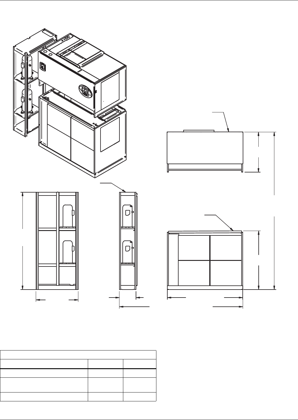
Air-Cooled Systems
Liebert® DS™40
Figure 32 Disassembly dimensions—upflow, air-cooled, 28-42kW (8-12 ton), scroll or digital scroll
compressors with centrifugal fans
Table 27 Component weights—upflow, air-cooled, 28-42kW (8-12 ton), scroll or digital scroll
compressors
Dry Weight, Approximate, Including Panels, lb (kg)
Component Air-Cooled Dual-Cool
Compressor Assembly 490 (223) 490 (223)
Blower and Electric Box Assembly
(Forward-Curved Fans) 510 (231) 510 (231)
Filter and Coil Assembly 520 (236) 670 (304)
Source: DPN001172, Rev. 1
NOTES: Drawing views are simplified with panels removed to show overall dimensions.
See disassembly and handling instructions in installation manual.
31-1/4"
(794mm)
76" (1930mm)
Assembled
Height
45-13/16"
(1163mm)
DPN001172
Rev. 1
59" (1499mm)
72"
(1829mm)
13"
(330mm)
33"
(838mm)
76"
(1930mm)
Compressor Assembly
Filter & Coil
Assembly
Blower & Electric
Box Assembly
Assembled Length
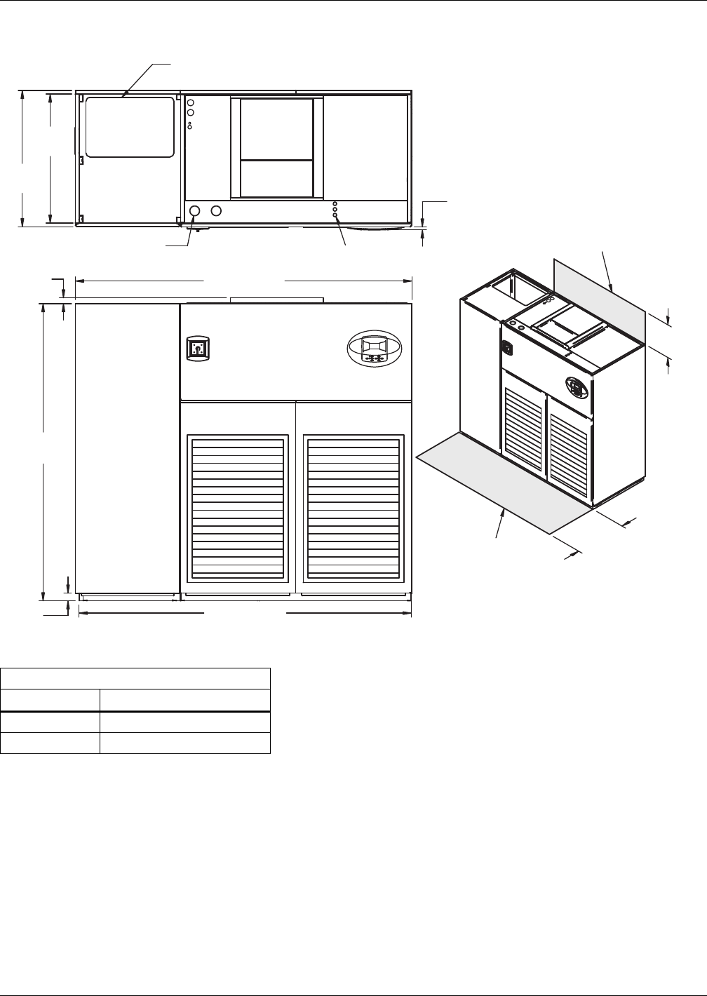
Air-Cooled Systems
41 Liebert® DS™
Figure 33 Dimensions—upflow, air-cooled, 28-42kW (8-12 ton), semi-hermetic compressors with
centrifugal fans
Table 28 Weights—upflow, air-cooled, 28-42kW (8-12 ton), semi-hermetic compressors
Dry Weight, Approximate, lb (kg)
Model Type Forward-Curved Fans
Air-Cooled 1830 (830)
Dual-Cool 1980 (898)
Source: DPN001162, Rev. 2
DPN001162
Rev. 2
33"
(838mm)
35"
(889mm)
1-1/2"
(38mm) 86" (2184mm)
TOP VIEW
76"
(1930mm)
High-Volt Connection(s)
2"
(51mm)
85" (2159mm)
34"
(864mm)
24"
(610mm)
Minimum required
for blower replacement
Shaded area indicates a
recommended minimum
clearance for component
access.
FRONT VIEW
3/4"
(19mm)
Bezels
Low-Volt
Connection(s)
Alternate Refrigerant
Piping Entrance
Note: Front air return unit shown. For
rear return unit, in addition to front service
area shown, also include 25" (635mm) on
one side of unit for access to rear return
filter box. See DPN001196.
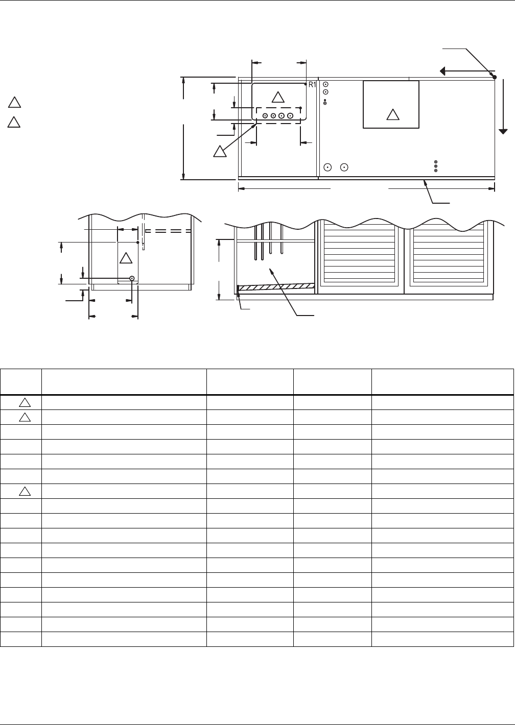
Air-Cooled Systems
Liebert® DS™42
Figure 34 Primary connection locations—upflow, air-cooled, 28-42kW (8-12 ton), semi-hermetic
compressors with centrifugal fans
Table 29 Piping data—upflow, air-cooled, 28-42kW (8-12 ton), semi-hermetic compressors
Point Description
X
in. (mm)
Y
in. (mm)
Connection Size / Opening
in. (mm)
R1 Refrigerant Access (Top) 60-11/16 (1542) 1-7/8 (48) 22-1/2 x 15-3/16 (572 x 386)
R2 Refrigerant Access (Bottom) 63 (1600) 13-13/16 (351) 16-7/16 x 4 (418 x 102)
L1 Liquid Line System 1 79-3/16 (2011) 16-3/4 (425) 1/2" Cu Sweat
L2 Liquid Line System 2 76-1/2 (1943) 16-3/4 (425) 1/2" Cu Sweat
G1 Hot Gas Discharge 1 73-7/8 (1876) 16-3/4 (425) 5/8" Cu Sweat
G2 Hot Gas Discharge 2 70-1/8 (1780) 16-3/4 (425) 5/8" Cu Sweat
R3 Refrigerant Access (Side) — — 6 x 17-3/16 (152 x 437)
CGD* Condensate Gravity Drain — — 3/4" FPT
CPD Condensate Pump Discharge (Opt) 56-1/4 (1429) 11-1/8 (283) 1/2" Cu Sweat
HUM Humidifier Supply Line 56-1/4 (1429) 9-1/8 (233) 1/4" Cu Sweat
ECS** Econ-O-Coil Supply 56 (1423) 7-5/16 (186) 1-5/8" Cu Sweat
ECR** Econ-O-Coil Return 56 (1423) 4-1/2 (114) 1-5/8" Cu Sweat
E1 Electrical Conn. (High Volt) 52-3/8 (1330) 30" (762mm) 2-1/2"
E2 Electrical Conn. (High Volt) 46-7/8 (1191) 30" (762mm) 2-1/2"
LV1 Electrical Conn. (Low Volt) 19-1/2 (495) 29-1/16 (738) 7/8"
LV2 Electrical Conn. (Low Volt) 19-1/2 (495) 30-1/2 (775) 7/8"
LV3 Electrical Conn. (Low Volt) 19-1/2 (495) 31-15/16 (811) 7/8"
* Field pitch condensate drain line a minimum of 1/8" (3.2 mm) per foot (305 mm). All units contain a factory-installed condensate trap. Do
not trap external to the unit. Drain line may contain boiling water. Select appropriate drain system materials. The drain line must comply
with all local codes.
** Supplied on Dual-Cool systems only (four-pipe system)
Piping dimensions shown are connection sizes; field piping sizes may be different depending on distance. Refer to user manual, SL-18825.
Source: DPN001114, Rev. 2
All dimensions from
rear corner of unit
including panels
Blower
Outlet
22-1/2"
(572mm)
NOTES:
1. Drawing not to scale.
2. Tolerance on all piping dimensions
is ± 1/2" (13mm).
Field-routed alternatives for refrigerant
gas and liquid line connection points.
See submittal page DPN001120 for
blower outlet and deck dimensional data. 16-7/16"
(418mm)
4"
(102mm)
35"
(889mm)
15-3/16"
(386mm)
86" (2184mm)
TOP VIEW Front of Unit
20-1/16"
(509mm)
Factory Location
FRONT SECTION VIEW
(Left Front Panel Not Shown)
14-1/4"
(362mm)
6"
(152mm)
17-3/16"
(437mm)
3-7/8"
(98mm) 15-7/8"
(403mm)
LEFT SIDE SECTION VIEW
DPN001114
Rev. 2
CGD *
CGD *
L1
G1
L2 G2
E1
ECR
ECS
HUM
CPD
E2
LV1
LV2
LV3
G1L2L1 G2
R3
R2
3
3
3
4
X0
Y
3
4
3
3
3
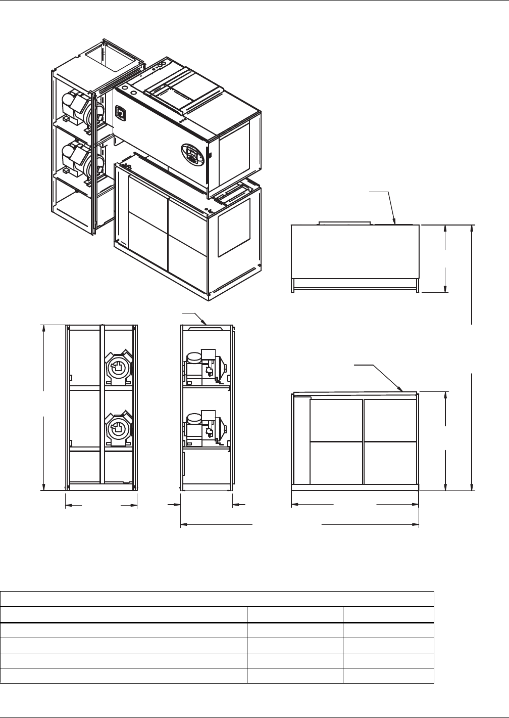
Air-Cooled Systems
43 Liebert® DS™
Figure 35 Disassembly dimensions—upflow, air-cooled, 28-42kW (8-12 ton), semi-hermetic compressors
with centrifugal fans
Table 30 Component weights—upflow, air-cooled, 28-42kW (8-12 ton), semi-hermetic compressors
Dry Weight, Approximate, Including Panels, lb (kg)
Component Air-Cooled Dual-Cool
Compressor Assembly 800 (364) 800 (364)
Blower and Electric Box Assembly (Forward-Curved Fans) 510 (231) 510 (231)
Blower and Electric Box Assembly (EC Fans) 360 (163) 360 (163)
Filter and Coil Assembly 520 (236) 670 (304)
Source: DPN001171, Rev. 1
DPN001171
Rev. 1
31-1/4"
(794mm)
45-13/16"
(1163mm)
76"
(1930mm)
Assembled\
Height
85" (2159mm)
Assembled Length
59"
(1499mm)
26"
(660mm)
NOTES: Drawing views are simplified with panels removed to show overall dimensions.
See disassembly and handling instructions in installation manual.
33"
(838mm)
76"
(1930mm)
Compressor Assembly
Blower & Electric
Box Assembly
Filter & Coil
Assembly
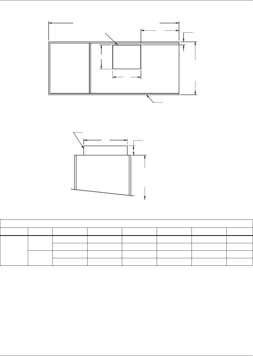
Air-Cooled Systems
Liebert® DS™44
Figure 36 Blower outlet and deck dimensions—upflow, air-cooled, 28-42kW (8-12 ton) with centrifugal
fans
Table 31 Blower outlet and deck dimensions—upflow, air-cooled, 28-42kW (8-12 ton)
Dimensional data, in. (mm)
Model Blower Supply A B C D E
28-42kW
(8-12ton)
15 x 15 Front Throw 15-7/8 (404) 18-5/8 (472) 2-1/8 (54) 25-5/8 (651) 25 (635)
Rear Throw 15-7/8 (404) 18-5/8 (472) 11-5/8 (295) 25-5/8 (651) 25 (635)
15 x 11 Front Throw 15-7/8 (404) 14-1/2 (368) 2-1/8 (54) 25-5/8 (651) 25 (635)
Rear Throw 15-7/8 (404) 14-1/2 (368) 11-5/8 (295) 25-5/8 (651) 25 (635)
Source: DPN001120, Rev. 3
E C
B
A
D
73" (1854mm) or 86" (2184mm) Ref
35"
(889mm)
Ref
76"
(1930mm)
Ref
1-1/2"
(38mm)
Blower Deck
DPN001120
Rev. 3
Blower Outlet *
* Duct flange not provided
Blower Outlet Location - Top View
Top of Unit
Front or Rear Throw Air Supply
Front of Unit
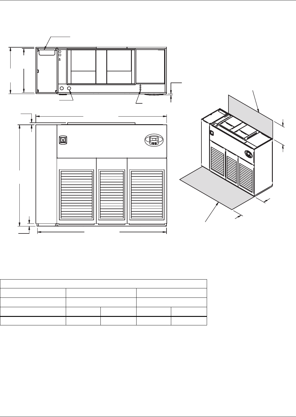
Air-Cooled Systems
45 Liebert® DS™
3.9 DIMENSIONS—LIEBERT DS 053-077, UPFLOW, AIR-COOLED MODELS
Figure 37 Dimensions—upflow, air-cooled, 53-77kw (15-22 ton), scroll or digital scroll compressors with
centrifugal fans
Table 32 Weights - upflow, air-cooled, 53-77kw (15-22 ton)—scroll or digital scroll compressors
Dry Weight, Approximate, lb (kg)
Model # 053, 042 077 *
Compressor Type Scroll/Digital Scroll Standard Scroll
Fan Type Air-Cooled Dual-Cool Air-Cooled Dual-Cool
Forward-Curved Blowers 2070 (939) 2250 (1021) 2070 (939) 2250 (1021)
* Digital scroll compressors not available on DS 077
Source: DPN001166, Rev. 2
33"
(838mm)
NOTE: Front air return unit shown. For rear return unit, in addition to front service
area shown, also include 25" (635mm) on one side of unit for access to rear
return filter box. See DPN001196.
1-1/2"
(38mm)
TOP VIEW
High-Volt Connection(s)
Alternate Refrigerant
Piping Entrance
Low-Volt
Connection(s)
FRONT VIEW
DPN001166
Rev. 2
3/4"
(19mm) Bezels
35"
(889mm)
76"
(1930mm)
2"
(51mm)
98" (2489mm)
97" (2464mm)
Shaded area indicates a
recommended minimum
clearance for component access.
24"
(610mm)
34"
(864mm)
Minimum required
for blower replacement
Digital scroll compressors
not available on DS 077.
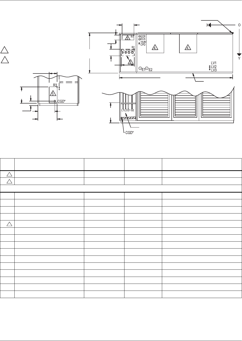
Air-Cooled Systems
Liebert® DS™46
Figure 38 Primary connection locations—upflow, air-cooled, 53-77kw (15-22 ton), scroll compressors
with centrifugal fans
Table 33 Piping data - upflow, air-cooled, 53-77kw (15-22 ton)—scroll compressors ***
Point Description
X
in. (mm)
Y
in. (mm) Connection Size / Opening, in. (mm)
R1 Refrigerant Access (Top) 83-5/8 (2124) 2 (51) 12 x 4 (305 x 102)
R2 Refrigerant Access (Bottom) 82-3/4 (2102) 14-3/4 (374) 12-3/16 x 4 (310 x 102)
53kW (15 ton) / 70 & 77kW (20 & 22 ton)
L1 Liquid Line System 1 94-11/16 (2405) 16-3/4 (425) 1/2" / 5/8" Cu Sweat
L2 Liquid Line System 2 91-7/8 (2334) 16-3/4 (425) 1/2" / 5/8" Cu Sweat
G1 Hot Gas Discharge 1 88-3/4 (2254) 16-3/8 (416) 7/8" / 1-1/8" Cu Sweat
G2 Hot Gas Discharge 2 85-9/16 (2173) 16-3/8 (416) 7/8" / 1-1/8" Cu Sweat
R3 Refrigerant Access (Side) — — 6 x 17-3/16 (152 x 437)
CGD* Condensate Gravity Drain — — 3/4" FPT
CPD Condensate Pump Discharge (Opt) 79-5/16 (2015) 11-7/8 (302) 1/2" Cu Sweat
HUM Humidifier Supply Line 79-5-16 (2015) 9-7/8 (251) 1/4" Cu Sweat
ECS Econ-O-Coil Supply 78-5/8 (1998) 7-7/8 (200) 2-1/8" Cu Sweat
ECR Econ-O-Coil Return 78-5/8 (1998) 4-5/8 (117) 2-1/8" Cu Sweat
E1 Electrical Conn. (High Volt) 75-3/8 (1915) 30 (762) 2-1/2"
E2 Electrical Conn. (High Volt) 69-7/8 (1775) 30 (762) 2-1/2"
LV1 Electrical Conn. (Low Volt) 19-1/2 (495) 29-1/16 (738) 7/8"
LV2 Electrical Conn. (Low Volt) 19-1/2 (495) 30-1/2 (775) 7/8"
LV3 Electrical Conn. (Low Volt) 19-1/2 (495) 31-15/16 (811) 7/8"
* Field pitch condensate drain line a minimum of 1/8" (3.2 mm) per foot (305 mm). All units contain a factory installed condensate trap. Do not
trap external to the unit. Drain line may contain boiling water. Select appropriate drain system materials. The drain line must comply with all
local codes.
** Supplied on dual-cool systems only.
*** Digital scroll compressors not available on DS 077
Piping dimensions shown are connection sizes; field piping sizes may be different depending on distance. Refer to user manual, SL-18825.
Source: DPN001213, Rev. 1
NOTES:
1. Drawing not to scale.
2. Tolerance on all piping dimensions
is ± 1/2" (13mm).
3. Field-routed alternatives for refrigerant
gas and liquid line connection points.
4. See submittal page DPN001191 for
blower outlet and deck dimensional data.
6"
(152mm)
17-1/16"
(433mm)
Factory
Location
DPN001213
Rev. 1
LEFT SIDE SECTION VIEW OF UNIT FRONT SECTION VIEW OF UNIT
(Left Front Panel Not Shown)
14-1/4"
(362mm)
15-7/8"
(403mm)
3-7/8"
(98mm)
17-3/16"
(437mm)
TOP VIEW OF UNIT
All dimensions from
rear corner of unit
including panels
12-13/16"
(325mm)
12" (305mm)
35"
(889mm)
98" (2489mm)
4"
(102mm)
4"
(102mm)
Front of Unit
Blower
Outlet
Blower
Outlet
Digital scroll compressors not
available on DS 077.
3
3
3
Air-Cooled Systems
47 Liebert® DS™
Figure 39 Disassembly dimensions—upflow, air-cooled, 53-77kw (15-22 ton), scroll or digital scroll
compressors with centrifugal fans
Table 34 Component weights—upflow, air-cooled, 53-77kw (15-22 ton), scroll or digital scroll
compressors
Dry Weight, Approximate, Including Panels, lb (kg)
Model # 053, 070 077
Compressor Scroll/Digital Scroll Standard Scroll *
Component Air-Cooled Dual-Cool Air-Cooled Dual-Cool
Compressor Assembly 540 (246) 540 (246) 540 (246) 540 (246)
Blower and Electric Box Assembly
Forward-Curved Fans 770 (349) 770 (349) 770 (349) 770 (349)
Filter and Coil Assembly 760 (345) 940 (426) 760 (345) 940 (426)
* Digital scroll compressors not available on DS 077
Source: DPN001210, Rev. 1
82" (2083mm)
NOTES: Drawing views are simplified with panels removed to show overall dimensions.
See disassembly and handling instructions in installation manual.
33"
(838mm)
76"
(1930mm)
DPN001210
Rev. 1
15"
(381mm)
Compressor Assembly
Blower & Electric
Box Assembly
Filter & Coil
Assembly
45-13/16"
(1163mm)
31-1/4"
(794mm)
76"
(1930mm)
Assembled
Height
97" (2464mm) Assembled Length
Digital scroll compressors
not available on DS 077.
Air-Cooled Systems
Liebert® DS™48
Figure 40 Dimensions—upflow, air-cooled 53-77kw (15-22 ton), semi-hermetic compressors with
centrifugal fans
Table 35 Weights—upflow, air-cooled, 53-77kW (15-22 ton), semi-hermetic compressors
Dry weight, including panels, lb. (kg)
Model Type
053 070, 077
Air-Cooled Dual-Cool Air-Cooled Dual-Cool
Forward-Curved Fans 2350 (1069) 2530 (1150) 2500 (1134) 2680 (1216)
Source: DPN001165, Rev. 2
33"
(838mm)
NOTE: Front air return unit shown. For rear return unit, in addition to front service
area shown, also include 25" (635mm) on one side of unit for access to rear
return filter box. See DPN001196.
1-1/2"
(38mm)
TOP VIEWHigh-Volt Connection(s)
Alternate Refrigerant
Piping Entrance
Low-Volt
Connection(s)
FRONT VIEW
DPN001165
Rev. 2
3/4"
(19mm) Bezels
35"
(889mm)
76"
(1930mm)
2"
(51mm)
109" (2769mm)
108" (2743mm) Shaded area indicates a
recommended minimum
clearance for component access.
24"
(610mm)
34"
(864mm)
Minimum required
for blower replacement
Air-Cooled Systems
49 Liebert® DS™
Figure 41 Primary connection locations—upflow air-cooled 53-77kW (15-22 ton), semi-hermetic
compressors with centrifugal fans
Table 36 Piping data—upflow, air-cooled, 53-77kW (15-22 ton), semi-hermetic compressors
Point Description
X
in. (mm)
Y
in. (mm)
Connection Size / Opening
in. (mm)
R1 Refrigerant Access (Top) 83-3/4 (2127) 1-7/8 (48) 22-1/2 x 15-3/16 (572 x 386)
R2 Refrigerant Access (Bottom) 86 (2184) 13-7/8 (352) 16-7/16 x4 (418 x102)
53kW (15 ton) / 70 & 77kW (20 & 22 ton)
L1 Liquid Line System 1 97 (2464) 16-3/4 (425) 1/2" / 5/8" Cu Sweat
L2 Liquid Line System 2 93-5/16 (2370) 16-3/4 (425) 1/2" / 5/8" Cu Sweat
G1 Hot Gas Discharge 1 90-5/8 (2302) 16-5/8 (422) 7/8" / 1-1/8" Cu Sweat
G2 Hot Gas Discharge 2 88 (2235) 16-5/8 (422) 7/8" / 1-1/8" Cu Sweat
R3 Refrigerant Access (Side) — — 6 x 17-3/16 (152 x 437)
CGD* Condensate Gravity Drain — — 3/4 FPT
CPD Condensate Pump Discharge (Opt) 79-5/16 (2015) 11-7/8 (302) 1/2" Cu Sweat
HUM Humidifier Supply Line 79-5/16 (2015) 9-7/8 (251) 1/4" Cu Sweat
ECS Econ-O-Coil Supply 78-5/8 (1998) 7-7/8 (200) 2-1/8" Cu Sweat
ECR Econ-O-Coil Return 78-5/8 (1998) 4-5/8 (117) 2-1/8" Cu Sweat
E1 Electrical Conn. (High Volt) 75-3/8 (1915) 30 (762) 2-1/2"
E2 Electrical Conn. (High Volt) 69-7/8 (1775) 30 (762) 2-1/2"
LV1 Electrical Conn. (Low Volt) 19-1/2 (495) 29-1/16 (738) 7/8"
LV2 Electrical Conn. (Low Volt) 19-1/2 (495) 30-1/2 (775) 7/8"
LV3 Electrical Conn. (Low Volt) 19-1/2 (495) 31-15/16 (811) 7/8"
* Field pitch condensate drain line a minimum of 1/8" (3.2 mm) per foot (305 mm). All units contain a factory installed condensate trap. Do not
trap external to the unit. Drain line may contain boiling water. Select appropriate drain system materials. The drain line must comply with all
local codes.
** Supplied on dual-cool systems only.
Piping dimensions shown are connection sizes; field piping sizes may be different depending on distance. Refer to user manual, SL-18825.
Source: DPN001212, Rev. 2
NOTES:
1. Drawing not to scale.
2. Tolerance on all piping dimensions
is ± 1/2" (13mm).
3. Field-routed alternatives for refrigerant
gas and liquid line connection points.
4. See submittal page DPN001191 for
blower outlet and deck dimensions.
6"
(152mm)
20-1/16"
(509mm)
Factory Location
DPN001212
Rev. 2
LEFT SIDE SECTION VIEW OF UNIT FRONT SECTION VIEW OF UNIT
(Left Front Panel Not Shown)
14-1/4"
(362mm)
15-7/8"
(403mm)
3-7/8"
(98mm)
17-3/16"
(437mm)
TOP VIEW OF UNIT
All dimensions from
rear corner of unit
including panels
XO
Y
16-7/16"
(418mm)
15-3/16"
(386mm)
22-1/2"
(572mm)
35"
(889mm)
109" (2769mm)
Blower
Outlet
Blower
Outlet
4"
(102mm)
Front of Unit
CGD *
3
3
3
Air-Cooled Systems
Liebert® DS™50
Figure 42 Disassembly dimensions—upflow, air-cooled, 53-77kW (15-22 ton), semi-hermetic
compressors with centrifugal fans
Table 37 Component weights—upflow air-cooled 53-77kw (15-22 ton), semi-hermetic compressors
Dry Weight, Approximate, Including Panels, lb (kg)
Component Air-Cooled Dual-Cool
Compressor Assembly 970 (441) 970 (441)
Blower and Electric Box Assembly
Forward-Curved Fans 770 (349) 770 (349)
Filter and Coil Assembly 760 (345) 940 (426)
Source: DPN001209, Rev. 1
82" (2083mm)
NOTES: Drawing views are simplified with panels removed to show overall dimensions.
See disassembly and handling instructions in installation manual.
33"
(838mm)
76"
(1930mm)
DPN001209
Rev. 1
26"
(660mm)
Compressor Assembly
Blower & Electric
Box Assembly
Filter & Coil
Assembly
45-13/16"
(1163mm)
31-1/4"
(794mm)
76" (1930mm)
Assembled Height
108" (2743mm)
Assembled Length
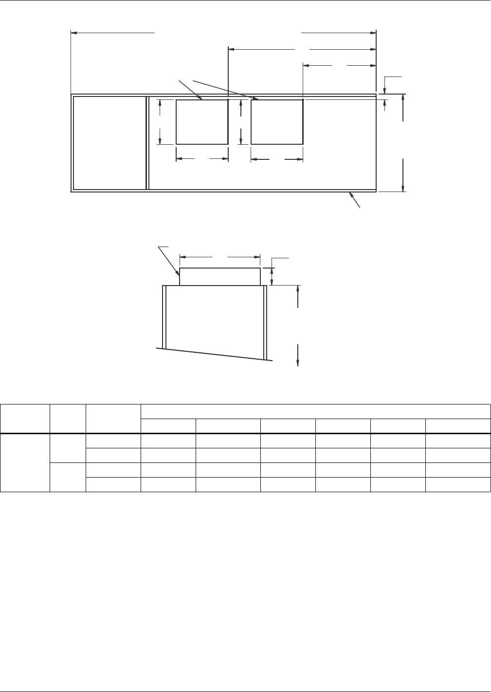
Air-Cooled Systems
51 Liebert® DS™
Figure 43 Blower outlet and deck dimensions—upflow 53-77kW (15-22 ton) with centrifugal fans
Table 38 Blower outlet and deck dimension—upflow, 53-77kW (15-22 ton)
Models Blower Supply
Dimensional Data, in. (mm)
ABCDEF
53-77kW
(15-22 ton)
15 x 15 Front Throw 15-7/8 (404) 18-5/8 (472) 2-1/8 (54) 25-5/8 (651) 27-3/4 (705) 55-1/2 (1410)
Rear Throw 15-7/8 (404) 18-5/8 (472) 11-5/8 (295) 25-5/8 (651) 27-3/4 (705) 55-1/2 (1410)
15 x 11 Front Throw 15-7/8 (404) 14-11/16 (373) 2-1/8 (54) 25-5/8 (651) 31-3/8 (797) 58-7/16 (1484)
Rear Throw 15-7/8 (404) 14-11/16 (373) 11-5/8 (295) 25-5/8 (651) 31-3/8 (797) 58-7/16 (1484)
Source: DPN001191, Rev. 6
Front or Rear Air Throw Supply
Blower Deck 1-1/2"
(38mm)
76"
(1930mm)
Ref.
DPN001191
Rev. 6
Blower Outlets *
98" (2449mm) or 109" (2769mm)
* Duct flanges not provided.
Blower Outlet Location - Top View
35"
(889mm)
Ref
Front of Unit
Top of Unit
B
C
E
F
B
AA
D
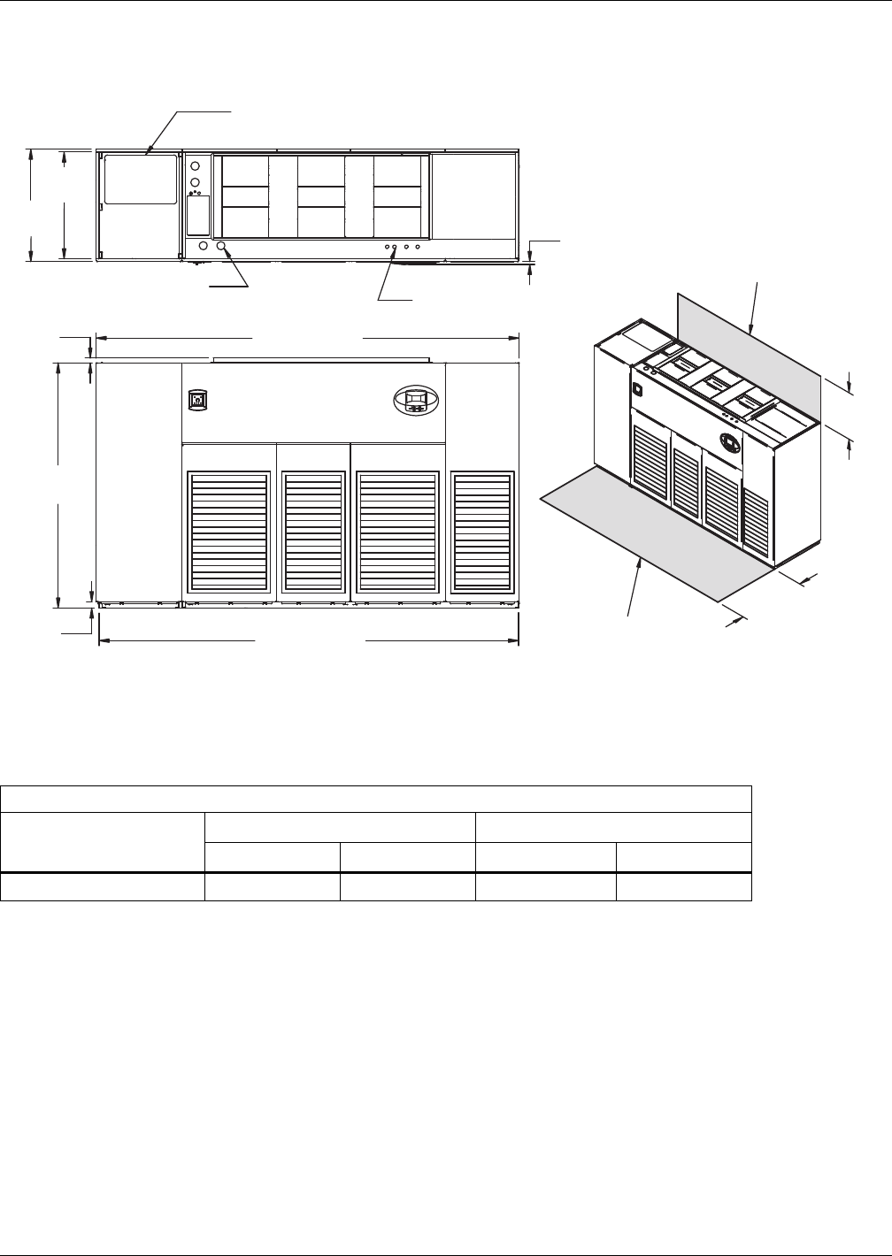
Air-Cooled Systems
Liebert® DS™52
3.10 DIMENSIONS—LIEBERT DS 105, UPFLOW, AIR-COOLED MODELS
Figure 44 Dimensions—upflow, air-cooled, 105kW (30 ton), semi-hermetic and scroll compressors with
centrifugal fans
Table 39 Weights—upflow, air-cooled, 105kW (30 ton), semi-hermetic and scroll compressors *
Dry Weight, Approximate, lb (kg)
Fan Type
Semi-Hermetic Scroll
Air-Cooled Dual-Cool Air-Cooled Dual-Cool
Forward-Curved Fans 3000 (1361) 3330 (1510) 2880 (1306) 3210 (1456)
* Digital scroll compressors not available on DS 105.
Source: DPN001168, Rev. 1
DPN001168
Rev. 1
FRONT VIEW
TOP VIEW
High-Volt Connection(s)
Alternate Refrigerant
Piping Entrance
Low-Volt Connection(s)
Shaded area indicates a
recommended minimum
clearance for component
access.
Minimum required
for blower replacement
Note: Front air return unit shown. For rear return unit, in addition to front
service area shown, also include 25" (635mm) on one side of unit
for access to rear return filter box. See DPN001196.
34"
(864mm)
24"
(610mm)
3/4"
(19mm)
Bezels
33"
(838mm)
35"
(889mm)
2"
(51mm)
76"
(1930mm)
1-1/2"
(38mm)
131" (3327mm)
132" (3353mm)
Digital scroll compressors
not available on 105 models.
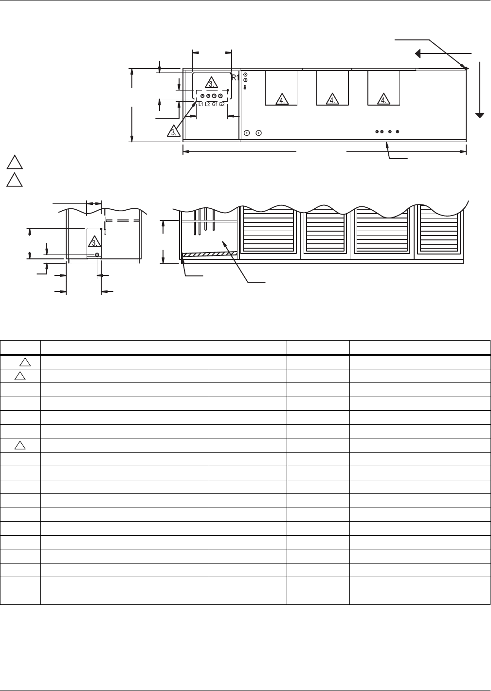
Air-Cooled Systems
53 Liebert® DS™
Figure 45 Primary connection locations—upflow, air-cooled, 105kW (30 ton), semi-hermetic and scroll
compressors with centrifugal fans
Table 40 Piping data—upflow, air-cooled 105kW (30 ton), semi-hermetic and scroll compressors ***
Point Description X, in. (mm) Y, in. (mm) Connection Size / Opening
R1 Refrigerant Access (Top) 106-7/8 (2715) 1-7/8 (48) 22-1/2 x 15-3/16 (572 x 386)
R2 Refrigerant Access (Bottom) 109-1/8 (2772) 13-7/8 (352) 16-7/16 x 4 (418 x 102)
L1 Liquid Line System 1 121-3/4 (3092) 16-3/4 (425) 5/8" Cu Sweat
L2 Liquid Line System 2 118-1/8 (3000) 16-3/4 (425) 5/8" Cu Sweat
G1 Hot Gas Discharge 1 118-1/4 (3004) 14-1/4 (362) 1-1/8" Cu Sweat
G2 Hot Gas Discharge 2 115-5/8 (2937) 14-1/4 (362) 1-1/8" Cu Sweat
R3 Refrigerant Access (Side) — — 6 x 17-3/16 (152 x 437)
CGD* Condensate Gravity Drain — — 3/4" FPT
CPD Condensate Pump Discharge (Opt) 102-3/8 (2600) 13-5/8 (346) 1/2" Cu Sweat
HUM Humidifier Supply Line 101-1/8 (2569) 13-1/8 (333) 1/4" Cu Sweat
ECS** Econ-O-Coil Supply 101-1/8 (2569) 10-1/4 (260) 2-5/8" Cu Sweat
ECR** Econ-O-Coil Return 101-1/8 (2569) 5-1/4 (133) 2-5/8" Cu Sweat
E1 Electrical Conn. (High Volt) 98-1/2 (2502) 30 (762) 2-1/2"
E2 Electrical Conn. (High Volt) 93 (2362) 30 (762) 2-1/2"
LV1 Electrical Conn. (Low Volt) 41-1/8 (1045) 30-3/8 (772) 7/8"
LV2 Electrical Conn. (Low Volt) 38-7/8 (987) 30-3/8 (772) 7/8"
LV3 Electrical Conn. (Low Volt) 35-1/8 (892) 30-3/8 (772) 7/8"
LV4 Electrical Conn. (Low Volt) 31-5/8 (803) 30-3/8 (772) 7/8"
* Field pitch condensate drain line a minimum of 1/8" (3.2 mm) per foot (305 mm). All units contain a factory-installed condensate trap. Do not
trap external to the unit. Drain line may contain boiling water. Select appropriate drain system materials. The drain line must comply with all
local codes.
** Supplied on dual-cool systems only.
*** Digital scroll compressors not available on DS 105
Piping dimensions shown are connection sizes; field piping sizes may be different depending on distance. Refer to user manual, SL-18825.
Source: DPN001257, Rev. 0
TOP VIEW
LV1
LV2
LV3
LV4
E1 E2
XO
ECS
ECR
HUM
CPD
Blower
Outlet
Blower
Outlet
Blower
Outlet
L1 L2
G1 G2
R2
CGD*
6"
(152mm)
20-1/16"
(509mm)
R3
Factory Location
FRONT SECTION VIEW
(Left Front Panel Not Shown)
LEFT SIDE SECTION VIEW
All dimensions from
rear corner of unit
including panels
Front Of Unit
DPN001257
Rev. 0
Y
3-7/8"
(98mm)
17-3/16"
(437mm)
CGD*
15-7/8"
(403mm)
16-7/16"
(418mm)
22-1/2"
(572mm)
15-3/16"
(386mm)
4"
(102mm)
14-1/4"
(362mm)
35"
(889mm)
132" (3353mm)
NOTES:
1. Drawing not to scale.
2. Tolerance on all piping dimensions
is ± 1/2" (13mm).
3. Field routed alternatives for refrigerant
gas and liquid line connection points.
4. See submittal page DPN001192 for
blower outlet and deck dimensional data.
Digital scroll compressors not
available on 105 models.
3
3
3
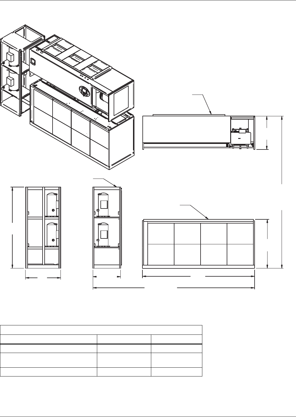
Air-Cooled Systems
Liebert® DS™54
Figure 46 Disassembly dimensions—upflow, air-cooled, 105kW (30 ton), standard scroll compressors
with centrifugal fans
Table 41 Component weights—upflow, air-cooled, 105kW (30 ton), standard scroll compressors *
Dry Weight, Approximate, Including Panels, lb (kg)
Component Air-Cooled Dual-Cool
Compressor Assembly 830 (376) 830 (376)
Blower and Electric Box Assembly
Forward-Curved Fans 1080 (490) 1080 (490)
Filter and Coil Assembly 970 (440) 1300 (590)
*Digital scroll compressors not available on DS 105
Source: DPN001255, Rev. 1
DPN001255
Rev. 1
31-1/4"
(794mm)
33"
(838mm)
76"
(1930mm)
26"
(660mm)
Filter & Coil Assembly
Compressor
Assembly
Blower & Electric
Box Assembly
NOTE: Drawing views are simplified with panels removed to show overall dimensions.
See disassembly and handling instructions in installation manual.
105"
(2667mm)
131" (3327mm
Assembled Length
45-13/16"
(1164mm)
76"
(1930mm)
Assembled
Height
Digital scroll compressors
not available on DS 105.
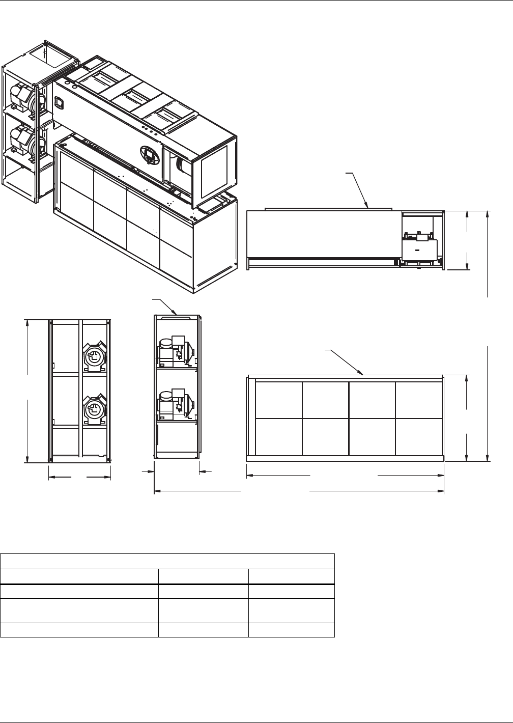
Air-Cooled Systems
55 Liebert® DS™
Figure 47 Disassembly dimensions—upflow, air-cooled, 105kW (30 ton), semi-hermetic compressors
with centrifugal fans
Table 42 Component weights—upflow, air-cooled, 105kW (30 ton), semi-hermetic compressors
Dry Weight, Approximate, Including Panels, lb (kg)
Component Air-Cooled Dual-Cool
Compressor Assembly 950 (431) 950 (431)
Blower and Electric Box Assembly
Forward-Curved Fans 1080 (490) 1080 (490)
Filter and Coil Assembly 970 (440) 1300 (590)
Source: DPN001254, Rev. 0
DPN001254
Rev. 1
31-1/4"
(794mm)
33"
(838mm)
76"
(1930mm)
26"
(660mm)
Filter & Coil
Assembly
Compressor
Assembly
Blower & Electric
Box Assembly
NOTES: Drawing views are simplified with panels removed to show overall dimensions.
See disassembly and handling instructions in installation manual.
105" (2667mm)
131" (3327mm
Assembled Length
45-13/16"
(1164mm)
76"
(1930mm)
Assembled
Height

Air-Cooled Systems
Liebert® DS™56
Figure 48 Blower outlet and deck dimensions—upflow 105kW (30 ton), with centrifugal fans
Table 43 Blower outlet and deck dimension—upflow 105kW (30 ton), with centrifugal fans
Blower SUPPLY
Dimensional Data, in. (mm)
ABCDEFG
15 x 11 Front Throw 15-7/8 (404) 14-11/16 (373) 2-1/8 (54) 25-5/8 (651) 30-3/4 (781) 54-1/2 (1384) 78-1/8 (1984)
Rear Throw 15-7/8 (404) 14-11/16 (373) 11-5/8 (295) 25-5/8 (651) 30-3/4 (781) 54-1/2 (1384) 78-1/8 (1984)
Source: DPN001192, Rev. 1
76"
(1930mm)
Ref
DPN001192
Rev. 1
1-1/2"
(38mm)
Blower Deck
Front or Rear Throw Air Supply
TOP OF UNIT
Blower Outlets *
BLOWER OUTLET LOCATION - TOP VIEW
35"
(889mm)
Ref
132" (3353mm)
* Duct flanges not provided
Front of Unit
F
EC
A
B
G
A
B
A
B
Air-Cooled Systems
57 Liebert® DS™
3.11 HEAT REJECTION—LIEBERT MC, FIN/TUBE AND PIGGYBACK CONDENSERS
3.11.1 Liebert MC Microchannel Condensers
Liebert MC Condenser Selection
Table 44 Traditional open room (75°F/45RH return air conditions)
Model #
Outdoor Design Ambient Temperature
95°F (35°C) 100°F (38°C) 105°F (41°C) 110°F (43°C) 115°F (46°C) 120°F (49°C)
DS/VS028A MCM080_8 MCM080_8 MCM080_8 MCL110_8 MCL110_8 MCL110_8
DS/VS035A MCM080_8 MCM080_8 MCM080_8 MCL110_8 MCL110_8 MCL110_8
DS/VS042A MCM080_8 MCM080_8 MCL110_8 MCL110_8 MCL110_8 MCL110_8
DS/VS053A MCM080_8 MCM080_8 MCL110_8 MCM160_8 MCM160_8 MCL220_8
DS/VS070A MCM080_8 MCL110_8 MCL110_8 MCM160_8 MCM160_8 MCL220_8
DS/VS077A MCM080_8 MCL110_8 MCL110_8 MCM160_8 MCM160_8 MCL220_8
DS/VS105A MCL110_8 MCM160_8 MCM160_8 MCL220_8 MCL220_8 MCL220_8
Table 45 High-temperature return (85°F/33RH return air conditions)
Model #
Outdoor Design Ambient Temperature
95°F (35°C) 100°F (38°C) 105°F (41°C) 110°F (43°C) 115°F (46°C) 120°F (49°C)
DS/VS028A MCM080_8 MCM080_8 MCL110_8 MCL110_8 MCL110_8 MCM160_8
DS/VS035A MCM080_8 MCM080_8 MCL110_8 MCL110_8 MCM160_8 MCM160_8
DS/VS042A MCM080_8 MCL110_8 MCL110_8 MCM160_8 MCM160_8 MCM160_8
DS/VS053A MCL110_8 MCL110_8 MCM160_8 MCL220_8 MCL220_8 MCL220_8
DS/VS070A MCL110_8 MCM160_8 MCM160_8 MCL220_8 MCL220_8 MCL220_8
DS/VS077A MCL110_8 MCM160_8 MCM160_8 MCL220_8 MCL220_8 MCL220_8
DS/VS105A MCM160_8 MCL220_8 MCL220_8 MCL220_8 MCL220_8 —
Table 46 Traditional open room (75°F/45RH return air conditions) Liebert QuietLine™ sound levels
Liebert DS
Model #
Outdoor Design Ambient Temperature
95°F (35°C) 100°F (38°C) 105°F (41°C) 110°F (43°C) 115°F (46°C)
DS/VS028A MCM080E8 MCM080E8 MCL110E8 MCL110E8 MCL110E8
DS/VS035A MCM080E8 MCL110E8 MCL110E8 MCM160E8 MCM160E8
DS/VS042A MCM080E8 MCL110E8 MCL110E8 MCM160E8 MCM160E8
DS/VS053A MCL110E8 MCL110E8 MCM160E8 MCL220E8 MCL220E8
DS/VS070A MCL110E8 MCM160E8 MCL220E8 MCL220E8 MCL220E8
DS/VS077A MCL110E8 MCM160E8 MCL220E8 MCL220E8 MCL220E8
DS/VS105A MCM160E8 MCL220E8 Consult Factory
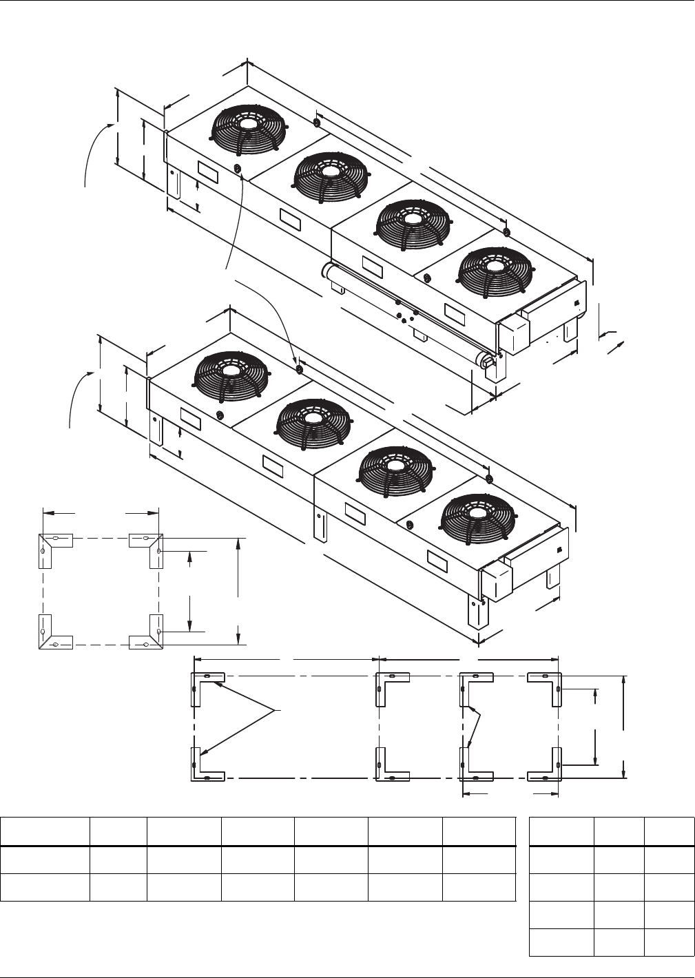
Air-Cooled Systems
Liebert® DS™58
Dimensions—Liebert MC™ Condensers
Figure 49 Condenser planning dimensions—MCM080, MCM160 with/without Liebert Lee-Temp™
Liebert
Model No.
No. of
Fans
A
in. (mm)
B
in. (mm)
C
in. (mm)
D
in. (mm)
E
in. (mm)
Leg Height
F* in. (m.)
G
in. (mm)
H
in. (mm)
MCM080 2 105-1/4
(2674) —96-1/16
(2440)
94-7/16
(2398) —18
(457)
31-5/8
(803)
39-5/8
(1006)
MCM160 4 202-7/16
(5142)
113-1/2
(2883)
192-1/4
(4883)
94-7/16
(2398)
96-3/16
(2444)
36
(914)
49-5/8
(1260)
57-5/8
(1464)
* Cross bracing required for legs longer than 18". Number of legs varies per model and options selected.
Source: DPN002172, Rev. 3; DPN002189, Rev4
48
(1219)
61-5/8
(1565)
69-5/8
(1768)
60
(1524)
73-5/8
(1870)
81-5/8
(2073)
DPN002172, Rev 3
DPN002189, Rev. 4
A
B
C
F
G
H
D
E
46-5/16"
(1177mm)
44-3/8"
(1127mm)
Leg supplied for
each Liebert
Lee-Temp kit on
2- & 4-fan models
Electric Box End
39-5/16"
(999mm)
46"
(1168mm)
46"
(1168mm)
15-1/4"
387mm
15-1/4"
387mm
For dual
circuit only
46-1/4"
(1175mm)
46-1/4"
(1175mm)
Height to Top
of Fan Guard
Height to Top
of Fan Guard
Provided On
Four-Fan Models
Emerson recommends a clearance of
36" (915mm) on each side for proper
operation and component access.
Eyebolts for lifting
condenser provided
on four-fan models
A
B
C
F
G
H
46-5/16"
(1177mm)
44-3/8"
(1127mm)
39-5/16"
(999mm)
One-Fan
Condenser
Electric Box End
ANCHOR PLAN
(One-Fan Condenser)
ANCHOR PLAN
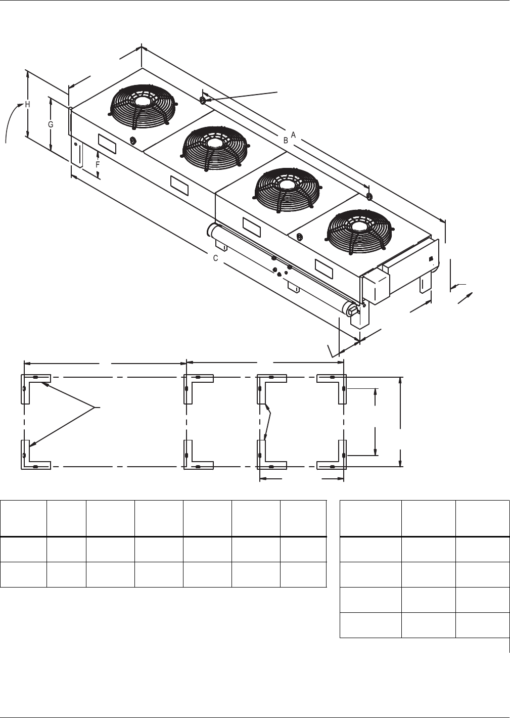
Air-Cooled Systems
59 Liebert® DS™
Figure 50 Cabinet and anchor dimensions—Liebert MC™ models MCL110 and MCL220 with Liebert Lee-
Temp receivers
Model
No
No. of
Fans
A
in. (mm)
B
in. (mm)
C
in. (mm)
D
in. (mm)
E
in (mm)
Leg
Height
F* in. (m.)
G
in. (mm)
H
in. (mm)
MCL110 2 124 1/8
(3152) — 112-1/8
(2848)
110-1/2
(2806) — 18 (457) 35-7/8
(911)
43-5/8
(1108)
MCL220 4 236-5/16
(6003)
129-9/16
(3291)
224-3/8
5699)
110-1/2
(2806)
112-1/4
(2851) 36 (914) 53-7/8
(1368)
61-5/8
(1565)
* Cross bracing required for legs longer than 18". Number of legs varies per model and
options selected.
Source: DPN002415, Rev. 3
48 (1219) 65-7/8
(1673)
73-5/8
(1870)
60 (1524) 77-7/8
(1978)
85-5/8
(2175)
Emerson recommends a clearance of
36" (915mm) on each side for proper
operation and component access.
Eyebolts for lifting condenser
provided on 3&4 fan models
55-1/2"
(1409mm)
15-1/4"
(387mm)
15-1/4"
(387mm)
For
Dual-Circuit
Only
53-7/8"
(1368mm)
55-5/8"
(1413mm)
Height
to Top
of Fan
Guard
54-3/8"
(1381mm)
Electric Box End
48-3/4"
(1239mm)
ANCHOR PLAN
(1) leg supplied for
each Liebert
Lee-Temp
kit on 2, 3, & 4
fan models
Provided on
3- & 4- Fan
Models
D
E
DPN002415
Rev. 3
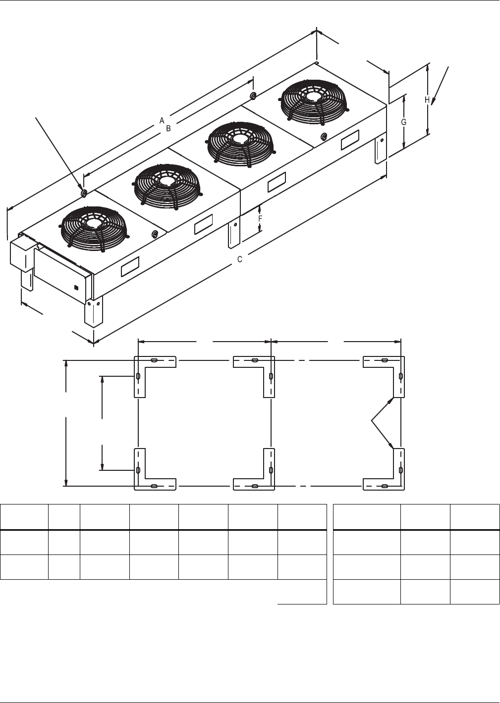
Air-Cooled Systems
Liebert® DS™60
Figure 51 Condenser planning dimensions—MCL110 and MCL220
Model #
# of
Fans
A
in. (mm)
B
in. (mm)
C
in. (mm)
D
in. (mm)
E
in. (mm)
Leg Height
F * In. (mm)
G
In. (mm)
H
In. (mm)
MCL110 2 124-1/8
(3152) —112-1/8
(2848)
110-1/2
(2806) — 18 (457) 35-7/8
(911)
43-5/8
(1108)
MCL220 4 236-5/16
(6003)
129-9/16
(3291)
224-3/8
(5699)
110-1/2
(2806)
112-1/4
(2851) 36 (914) 53-7/8
(1368)
61-5/8
(1565)
56-1/8
(1425) 48 (1219) 65-7/8
(1673)
73-5/8
(1870)
* 18" legs standard for all models. Cross-bracing required for legs longer than 18" (457mm). Number varies according to model and options.
Source: DPN002416, Rev. 2
Emerson recommends a clearance of
36" (915mm) on each side for proper
operation and component access.
Eyebolts for lifting condenser
provided on 3&4 fan models
55-5/8"
(1413mm)
55-1/2"
(1409mm)
53-7/8"
(1368mm)
Electric Box End
48-3/4"
(1239mm)
Height to Top
of Fan Guard
DPN002416
Rev. 2
ANCHOR PLAN
Provided on
3- & 4- Fan Models
DE
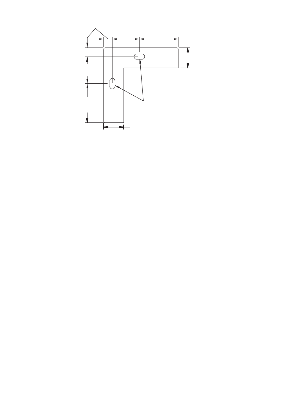
Air-Cooled Systems
61 Liebert® DS™
Figure 52 Typical Liebert MC™ condenser footprint—dimensions
1-7/8" (48mm)
13/16"
21mm
2-1/2"
(64mm)
2-1/2"
(64mm)
3-5/8"
(93mm)
3-5/8"
(93mm)
1/2"x1"
(12.7mm x 25.4mm)
Obround
1-7/8"
(48mm)
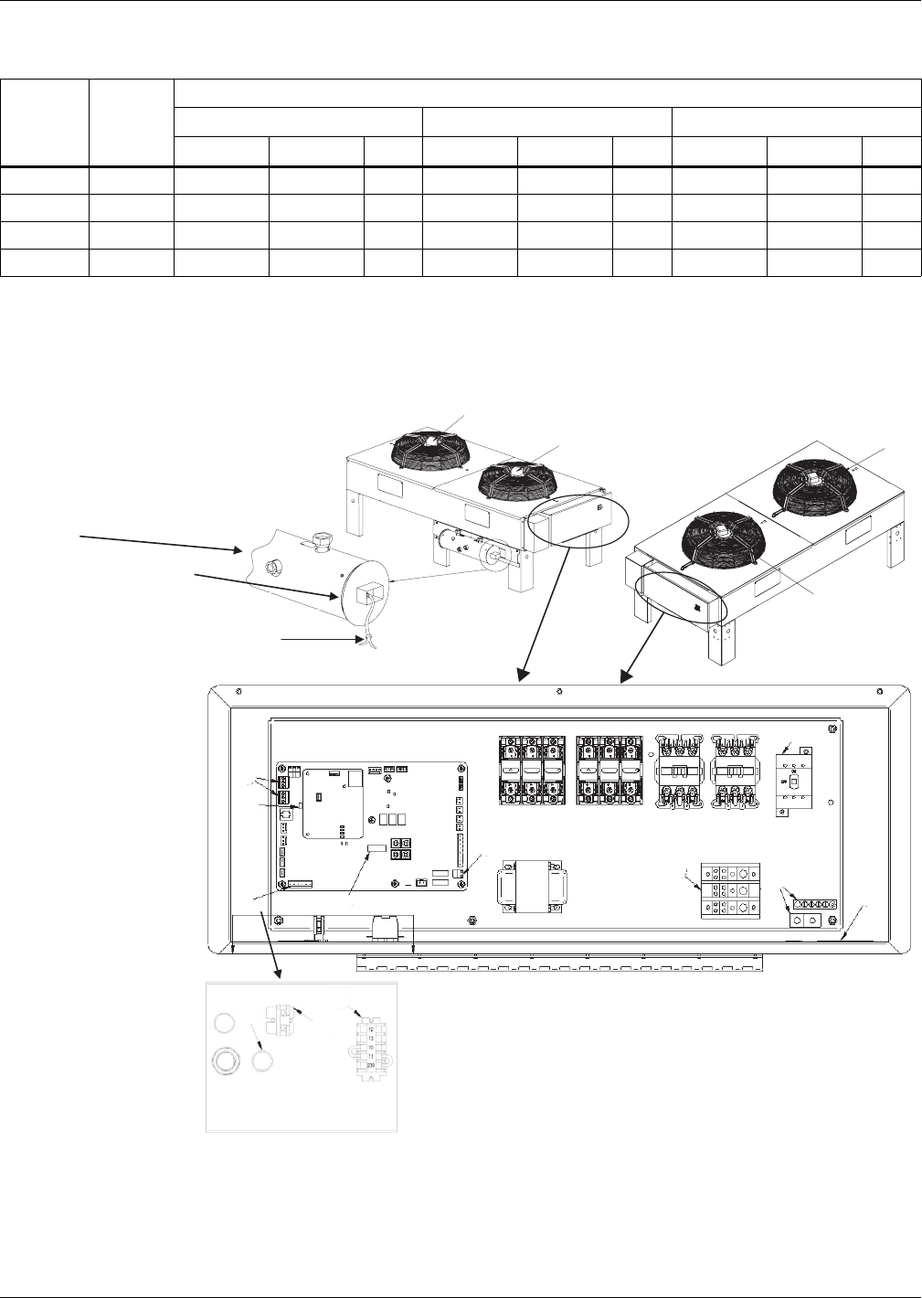
Air-Cooled Systems
Liebert® DS™62
Electrical Data—Liebert MC™ Condensers
Electrical Field Connections—Liebert MC Condensers
Figure 53 Electrical field connections—Liebert MC Condensers premium efficiency control, with and
without Liebert Lee-Temp
Table 47 Liebert MC electrical data, three-phase, 60Hz condenser, Premium Version (EC control)
Model #
Number
of Fans
Power Requirements
FLA WSA OPD
208/230V 380/415V 460V 208/230V 380/415V 460V 208/230V 380/415V 460V
MCM080 2 4.6 2.8 2.8 5.5 3.3 3.3 15 15 15
MCM160 4 9.2 5.6 5.6 9.8 6.0 6.0 15 15 15
MCL110 2 11.4 5.6 5.6 12.8 6.3 6.3 15 15 15
MCL220 4 22.8 11.2 11.2 24.2 11.9 11.9 25 15 15
1. FLA = Full Load Amps; WSA = Wire Size Amps; OPD = Maximum Overcurrent Protection Device.
2. 208V–460V premium models must be connected to Wye 3-phase systems.
Lee-Temp receiver tank (1 per circuit).
NOTE: Standard heater pads are 150 watt each.
(Optional 300 watt heater pads are available.)
Standard heater pad voltage is 230V.
(120V heater pad voltage is optional.)
Electrical Connection
Box with Cover
Electrical service connection. Pigtails in electric
handy box are factory-wired to Liebert Lee-Temp
heater pads for field-connection of separate
continuous electric source; wire not by Liebert
Fan 2
Fan 1
5A
1
6
5B
5C7
8
9
4
10
2
3
DPN002374
Pg. 2, Rev. 1
Fan 2
Fan 1
DPN002169
Rev. 3
See Electrical Connections—Premium
Efficiency Control, Liebert MC Condensers on
page 63 for key to numbered components

Air-Cooled Systems
63 Liebert® DS™
Electrical Connections—Premium Efficiency Control, Liebert MC Condensers
Key Electrical Details; Source: DPN002169, Rev. 3 and DPN002374 Rev. 2
1. Three-phase electrical service—Terminals are on top of disconnect switch for one-fan and
two-fan units. Terminals are on bottom of disconnect switch for three-fan and four-fan units.
Three-phase service not by Emerson. See Note 5.
2. Earth ground—Field lug terminal for earth ground connection. Ground terminal strip for fan
motor ground connection.
3. Primary high voltage entrance—Three 7/8" (22.2mm) diameter knockouts located at the
bottom of the enclosure.
4. SPD field connection terminals—High-voltage surge protection device (SPD) terminals. SPD
is an optional device.
5. CANbus terminal connections—Field terminals for CANbus cable connection.
• 5A is the CANbus connectors
• TB49-1 is the input terminal for CANbus high
• TB49-3 is the input terminal for CANbus low
• TB50-1 is output terminal for CANbus high
• TB50-3 is the output terminal for CANbus low
• Each CANbus cable shield is connected to terminal “SH”, Item 9.
• 5B is the “END OF LINE” jumper.
• 5C is the CANbus “DEVICE ADDRESS DIP SWITCH”. CANbus cable not by Emerson. See Note 2.
6. Remote unit shutdown—Replace exiting jumper between terminals TB38-1 and TB38-2 with
field-supplied normally closed switch having a minimum 75VA 24VAC rating. Use field-supplied
Class 1 wiring.
7. Alarm terminal connections
a. Common Alarm Relay indicates when any type of alarm occurs. TB74-1 is common; TB74-2 is
normally open; and TB74-3 is normally closed. 1 Amp 24VAC is the maximum load. Use
field-supplied Class 1 wiring.
b. Shutdown Alarm Relay indicates when condenser loses power or when a critical alarm has
occurred that shuts down the condenser unit. TB74-4 is common, TB74-5 is normally open
and TB74-6 is normally closed. 1 Amp 24VAC is the maximum load. Use field-supplied
Class 1 wiring.
8. Indoor unit interlock and SPD alarm terminals
a. On any call for compressor operation, normally open contact is closed across Terminals 70 &
71 for Circuit 1, and normally open contact is closed across Terminals 70 & 230 for Circuit 2
from indoor room unit.
b. During SPD alarm, normally open contact is closed across Terminals 12 &13. SPD is an
optional device.
9. CANbus shield terminal—Terminal for field connection of the CANbus field-supplied cables.
Shield of CANbus field-supplied cables must not be connected to ground at the condenser.
10. Primary low voltage entrance—One 7/8" (22.2mm) diameter knockout that is free for
customer low-voltage wiring.

Air-Cooled Systems
Liebert® DS™64
NOTES
1. Refer to specification sheet for unit voltage rating, full load amp and wire size amp ratings.
2. The CANbus wiring is field supplied and must be:
•shielded
• 22-18AWG stranded tinned copper,
• twisted pair (minimum 8 twists per foot),
• low capacitance (15pf/ft or less),
• plenum rated (NEC type CMP) if required by local codes,
• UV and moisture resistant or run within conduit once in an outdoor environment, and
• must be temperature and voltage rated for conditions present.
Examples: Belden part number 89207(plenum rated) or Alpha Wire part number 6454
(UV resistant outdoor rated) Category 5, 5e or higher.
3. Do not run the CANbus cable in the same conduit, raceway, or chase as high voltage.
4. For CANbus network lengths greater than 350ft. (107m), contact Liebert factory.
5. All wiring must be sized and selected for insulation case per NEC and other local codes.
6. The electrically commutated (EC) motors included in the Liebert MC condensers are suitable for
connection to power supplies with a solidly grounded neutral. (Some platforms can accept power
supplies listed under Item b below. Contact the factory for more information.)
a. Acceptable power supplies for 208 to 480V nominal units
• 208V wye with solidly grounded neutral and 120V line to ground;
• 380V wye with solidly grounded neutral and 220V line to ground;
• 480V wye with solidly grounded neutral and 277V line to ground.
b. Unacceptable power supplies for 208V to 480V nominal units:
• wye with high resistance (or impedance) ground;
• delta without ground or with floating ground;
• delta with corner ground; or
• delta with grounded center tap
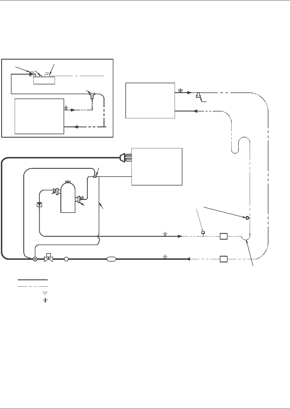
Air-Cooled Systems
65 Liebert® DS™
3.12 PIPING—LIEBERT MC™ CONDENSERS
Typical System Configurations—LIEBERT MC CONDENSERS
Figure 54 shows a single refrigeration circuit diagram, displaying the indoor air conditioning unit,
the outdoor condenser (with or without Liebert Lee-Temp™) and field-supplied interconnection piping.
Figure 54 Liebert MC piping schematic with and without Liebert Lee-Temp
Service/Schrader (Access) Connection With Valve Core
NOTES
Single refrigeration circuit shown for clarity.
Schematic representation shown. Do not use for specific connection locations.
* Components are not supplied by
Liebert but are recommended for
proper circuit operation and
maintenance
Refrigerant Piping
Field Piping
Service/Schrader (Access) Connection No Valve Core
Trap at base of risers
over 5ft. (1.5m)*
Condenser
Coil
Condenser
Coil
Liebert Lee-Temp Receiver
Liebert Lee-Temp
Hot Gas Discharge
Liquid Return
For rises over 25ft. (7.6m),
trap every 20ft. (6m) or at
evenly divided distances*
Evaporator
Coil
Liquid
Suction
Compressor
Expansion
Valve Solenoid
Valve
Sight
Glass Filter Drier Liquid Line
Hot Gas Discharge
*Isolation
Valve
*Isolation
Valve
Check
Valve
Field installed relief valve(s) required
for 50Hz EU CE units
Optional Field-Installed
Fusible Plug
Service
Valve
Check Valve
Relief Valve
Service
Valve
Head Pressure
Control Valve
Service
Valve
External
Equalizer
Sensing
Bulb
DPN002188
Rev. 1
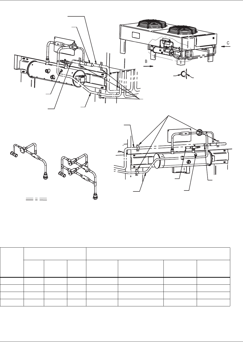
Air-Cooled Systems
Liebert® DS™66
Figure 55 Piping dimensions—Liebert MC™ dual circuit condensers with Liebert Lee-Temp™
Table 48 Piping dimensions—Liebert MC dual circuit condensers with Liebert Lee-Temp
Model #
Condenser Connections
ODS, in. Liebert Lee-Temp Connections
Circuit
No. Hot Gas Liquid
Hot Gas Tee
IDS, in.
Liquid Line
to Lee-Temp Valve
ODS, In.
Receiver Out
R407C
IDS, in.
Receiver Out
R410A
IDS, in.
MCM080 2 7/8 5/8 7/8 5/8 5/8 5/8
MCL110 2 1-1/8 7/8 1-1/8 7/8 7/8 7/8
MCM160 2 1-1/8 7/8 1-1/8 7/8 1-1/8 1-1/8
MCL220 2 1-3/8 1-1/8 1-3/8 1-1/8 1-1/8 1-1/8
Source: DPN002426, Rev. 4
Note:
1. The following materials are supplied by Emerson for each circuit (shipped loose with condenser)
for field installation: insulated Liebert Lee-Temp storage tank with sight glasses, head pressure control
valve, check valve, rotalock valve and pressure relief valve. All other piping to be supplied and installed by others.
2. Consult factory for proper line sizing for runs longer than 150ft. (45.7m) equivalent length.
Field Piping
Detail AA
Isolator
Metal Clamp
Fasten hot gas line to cabinet
using flat surface clamps with
isolators (field-supplied)
See Detail A A
Hot Gas Line
To Condenser
Entering Hot
Gas Line
Entering Hot
Gas Line
Liquid Line
From Condenser
Leaving
Liquid Line
Position elbow to
direct relief valve
downward
Position elbow to
direct relief valve
downward
Liquid Line
From Condenser
Leaving
Liquid Line
Hot Gas Line
To Condenser
Inverted traps in refrigerant
lines are internal to
the condenser. Do not trap
external to the unit.
R407C 2 and 4 Fan
Piping Assembly
R410A 2 Fan
Piping Assembly
Liebert-supplied piping assembly
will include one or two valve and check
valves, depending on condenser
capacity and refrigerant
R410A 4 Fan
Piping Assembly
GENERAL ARRANGEMENT
C View
DPN002426
Rev. 4
B View
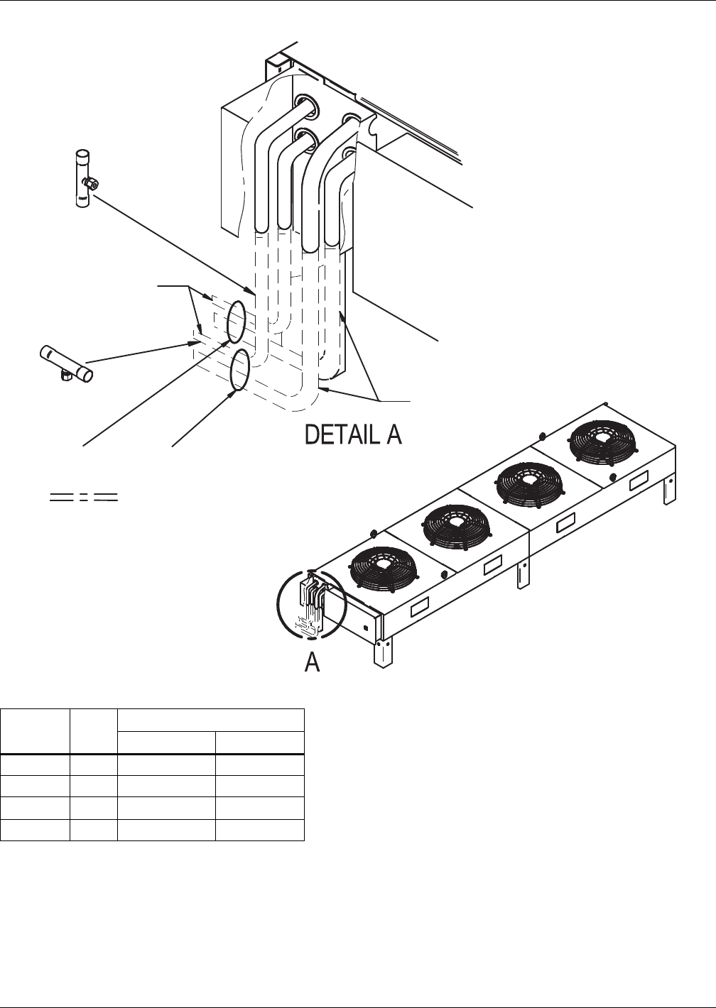
Air-Cooled Systems
67 Liebert® DS™
Figure 56 Piping connections—Liebert MC™ dual circuit two-fan and four-fan units
Table 48 Liebert MC piping connection sizes—Liebert MC dual-circuit, two-fan and four-fan units
Model #
# of
Fans
Connection Sizes, OD, in
Hot Gas Line Liquid Line
MCM080 2 7/8 5/8
MCL110 2 1-1/8 7/8
MCM160 41-1/8 7/8
MCL220 4 1-3/8 1-1/8
Source: DPN002425, Rev. 3
Optional fusible plug service kit to
be brazed into the liquid line(s) in
either the vertical or horizontal
position. (where required)
(vertical position is preferred,
horizontal position is optional.)
for two circuit systems, one
fusible plug kit will need to
be installed in each circuit.
Circuit #2
Circuit #1
Horizontal
Leaving Liquid
Line
Vertical
Field Piping
Entering Hot
Gas Line
Inverted traps in refrigerant
lines are internal to
the condenser. Do not trap
external to the unit.
DPN002425
Rev. 3
Air-Cooled Systems
Liebert® DS™68
3.12.1 Fin/Tube Condensers
Fin/Tube Selections
Dimensions—Fin/Tube Condensers
Table 49 Liebert DS air-cooled condenser selection, finned-tubular design, R-407C
Liebert DS
Model
Ambient Temperature °F (°C)
Outdoor Condenser Outdoor Quiet-Line Condenser
95 (35) 100 (38) 105 (41) 95 (35) 100 (38) 105 (41)
028 CD*-205 CD*-205 CD*-251 CD*-214 CD*-214 CD*-286
035 CD*-205 CD*-205 CD*-251 CD*-214 CD*-214 CD*-286
042 CD*-205 CD*-251 CD*-308 CD*-286 CD*-286 CD*-409
053 CD*-251 CD*-308 CD*-415 CD*-286 CD*-409 CD*-409
070 CD*-308 CD*-415 CD*-415 CD*-409 CD*-477 CD*-572
077 CD*-308 CD*-415 CD*-616 CD*-409 CD*-572 CD*-572
105 CD*-415 CD*-616 CD*-616 CD*-572 N/A N/A
Table 50 Fin/tube condenser physical data and R-407C refrigerant required per condenser circuit
Model
Number
Number
of Fans
Number
of Circuits
Connection Size, OD, In.
Net Weight
lb (kg)
Dual Circuit
lb/circuit (kg/circuit)
Hot Gas Liquid
FSC or
VFD
Liebert Lee-Temp
(includes receiver)
Standard Models
CD*165 2 2 7/8 5/8 425 (193) 5 (2.3) 26 (11.8)
CD*205 2 2 1-1/8 7/8 495 (225) 7 (3.2) 54 (24.4)
CD*251 3 2 1-1/8 7/8 500 (227) 10 (4.6) 36 (16.3)
CD*308 3 2 1-3/8 1-1/8 670 (304) 11 (5.0) 55 (24.9)
CD*415 4 2 1-3/8 1-1/8 840 (381) 24 (10.9) 102 (46.2)
CD*510 4 2 1-5/8 1-1/8 1188 (539) 29 (13.2) 142 (64.4)
CD*616 6 2 1-5/8 1-1/8 1380 (626) 26 (11.8) 108 (49.0)
Quiet-Line Models
DCD*143 2 2 1-1/8 7/8 515 (234) N/A 61 (27.7)
DCD*214 3 2 1-1/8 7/8 840 (381) N/A 77 (34.9)
DCD*286 4 2 1-1/8 7/8 1105 (501) N/A 119 (54.0)
DCD*409 6 2 1-5/8 1-1/8 1380 (626) N/A 125 (55.8)
DCD*572 8 2 2-1/8 1-1/8 2430 (1102) N/A 186 (84.4)
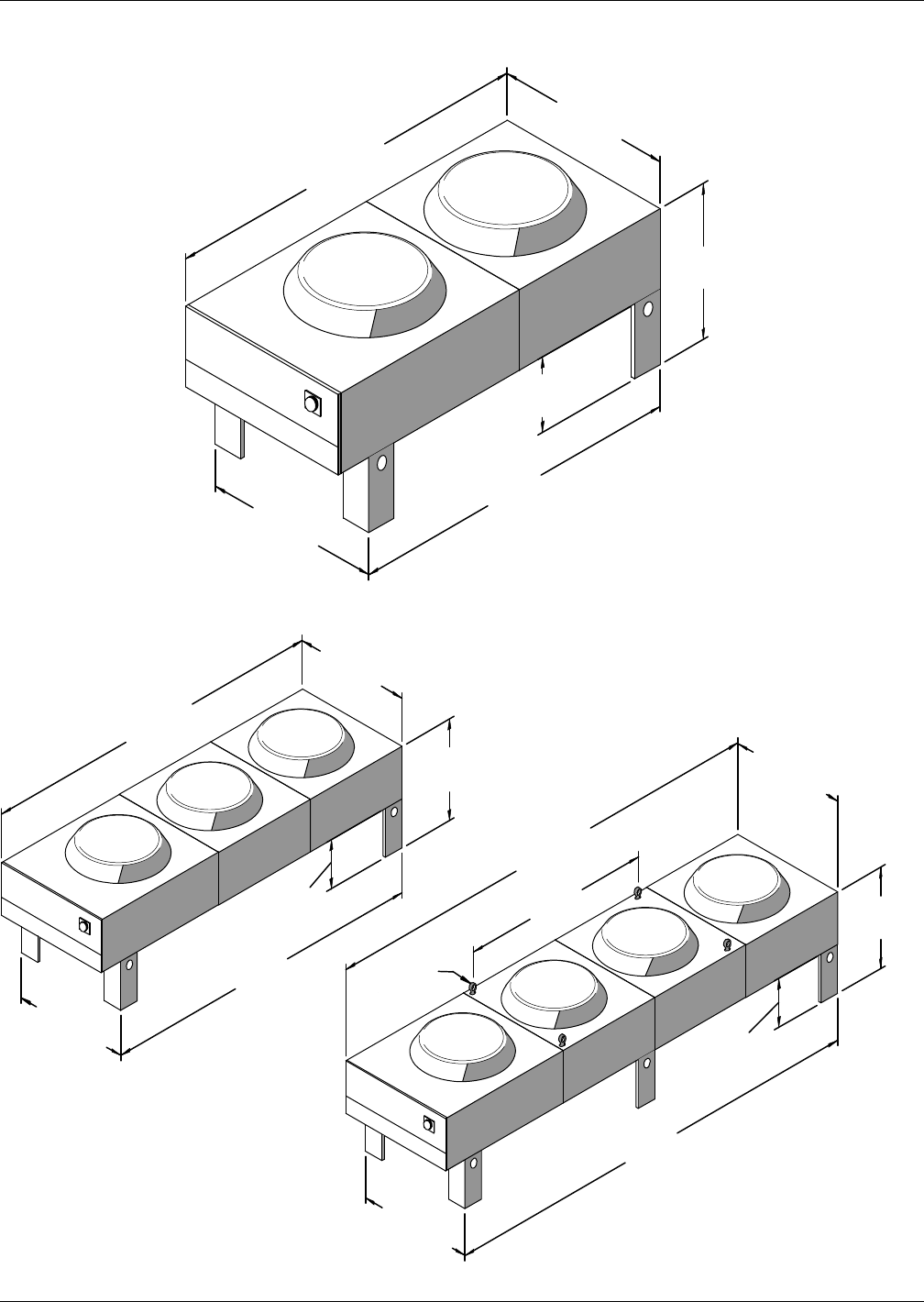
Air-Cooled Systems
69 Liebert® DS™
Figure 57 Fin/tube condenser dimensions, 2-fan model
Figure 58 Fin/tube condenser dimensions, 3-fan and 4-fan models
91-1/2"
(2324mm)
43-9/16"
(1106mm)
37-7/8"
(962mm)
18"
(457mm)
84"
(2134mm)
43-3/16"
(1097mm)
Emerson recommends a
clearance of 36" (915mm)
on each side for proper
operation and component
access.
Note:
Overall height to the top of fan guard
43-1/8" (1095mm)
Eyebolts
for Lifting
37-7/8"
(962mm)
37-7/8"
(962mm)
171-1/2"
(4356mm)
70"
(1778mm)
131-1/2"
(3340mm)
124"
(3150mm)
164"
(4166mm)
43-3/16"
(1097mm)
43-3/16"
(1097mm)
43-9/16"
(1106mm)
43-9/16"
(1106mm)
18"
(457mm)
18"
(457mm)
Emerson recommends a
clearance of 36" (915mm)
on each side for proper
operation and component
access.
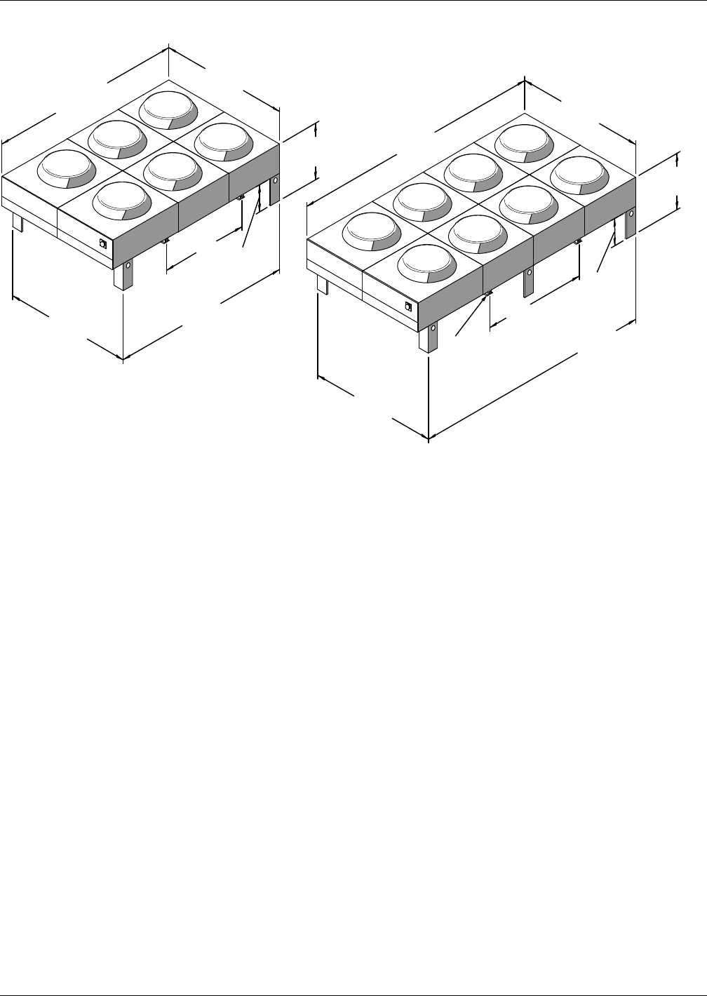
Air-Cooled Systems
Liebert® DS™70
Figure 59 Fin/tube condenser dimensions, 6-fan and 8-fan models
171-1/2"
(4356mm)
37-7/8"
(962mm)
131-1/2"
(3340mm)
18"
(457mm)
70" (1778mm)
86-3/4"
(2203mm)
86-3/4"
(2203mm)
124"
(3150mm)
164"
(4166mm)
Overalll height to the top
of the fan guard is 43-1/8” (1095mm).
1-1/2" (38mm)
diameter hole for
rigging (typ.4)
87-1/8"
(2213mm)
87-1/8"
(2213mm)
18"
(457mm)
59"
(1499mm)
37-7/8"
(962mm)
Emerson recommends
a clearance of 36"
(915mm) on each side
for proper operation
and component
access.
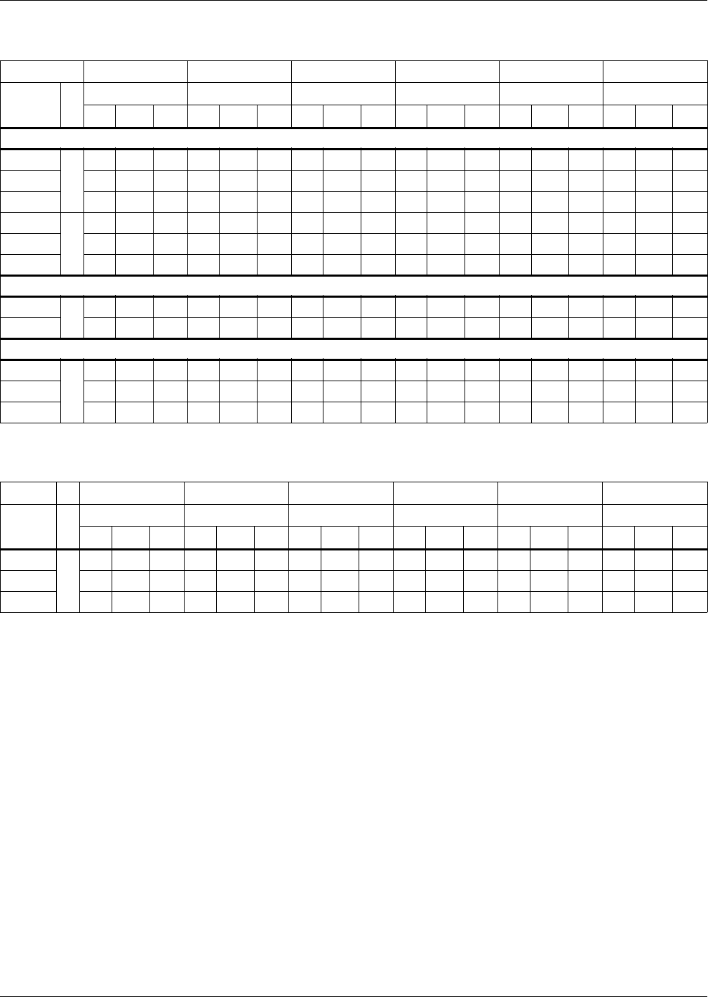
Air-Cooled Systems
71 Liebert® DS™
Electrical Data—Fin/Tube Condensers
Table 51 Fin/tube condenser data, 60Hz
Model # 83, 104 165, 205 251, 308 415, 510 616 830, 1010
Input
Voltage ph
1 Fan 2 Fans 3 Fans 4 Fans 6 Fans 8 Fans
FLA WSA OPD FLA WSA OPD FLA WSA OPD FLA WSA OPD FLA WSA OPD FLA WSA OPD
Fan Speed Controlled
208/230
1
4.86.015—— ——— ——— ——— ——— —
460 2.5 3.1 15 — — — — — — — — — — — — — — —
575 1.9 2.4 15 — — — — — — — — — — — — — — —
208/230
3
— — — 8.3 9.5 15 11.8 13.0 15 15.3 16.5 20 23.6 24.8 30 30.6 31.8 40
460 — — — 4.2 4.8 15 5.9 6.5 15 7.6 8.2 15 11.8 12.4 15 15.2 15.8 20
575 — — — 3.3 3.8 15 4.7 5.2 15 6.1 6.6 15 9.4 9.9 15 12.2 12.7 15
VFD Controlled
208/230 33.7 4.6 15 7.2 8.1 15 10.7 11.6 15 14.2 15.1 20 N/A N/A N/A N/A N/A N/A
460 1.8 2.3 15 3.5 4.0 15 5.2 5.7 15 6.9 7.4 15 N/A N/A N/A N/A N/A N/A
Lee-Temp Controlled/Fan-Cycling
208/230
3
3.5 4.4 15 7.0 7.9 15 10.5 11.4 15 14.0 14.9 20 21.0 21.9 25 28.0 28.9 35
460 1.7 2.1 15 3.4 3.8 15 5.1 5.5 15 6.8 7.2 15 10.2 10.6 15 13.6 14.0 20
575 1.4 1.8 15 2.8 3.2 15 4.2 4.6 15 5.6 6.0 15 8.4 8.8 15 11.2 11.6 15
FLA = Full Load Amps; WSA = Wire Size Amps; OPD = Maximum Overcurrent Protection Device
Table 52 Fin/tube condenser data, Liebert Quiet-Line™ (Liebert Lee-Temp™ controlled/fan-cycling), 60Hz
Model # ph 63 119, 127, 143 214 286 409 572
Input
Voltage ph
1 Fan 2 Fans 3 Fans 4 Fans 6 Fans 8 Fans
FLA WSA OPD FLA WSA OPD FLA WSA OPD FLA WSA OPD FLA WSA OPD FLA WSA OPD
208/230
3
1.8 2.3 15 3.6 4.1 15 5.4 5.9 15 7.2 7.7 15 10.8 11.3 15 14.4 14.9 20
460 0.9 1.1 15 1.8 2.0 15 2.7 2.9 15 3.6 3.8 15 5.4 5.6 15 7.2 7.4 15
575 0.7 0.9 15 1.4 1.6 15 2.1 2.3 15 2.8 3.0 15 4.2 4.4 15 5.6 5.8 15
FLA = Full Load Amps; WSA = Wire Size Amps; OPD = Maximum Overcurrent Protection Device
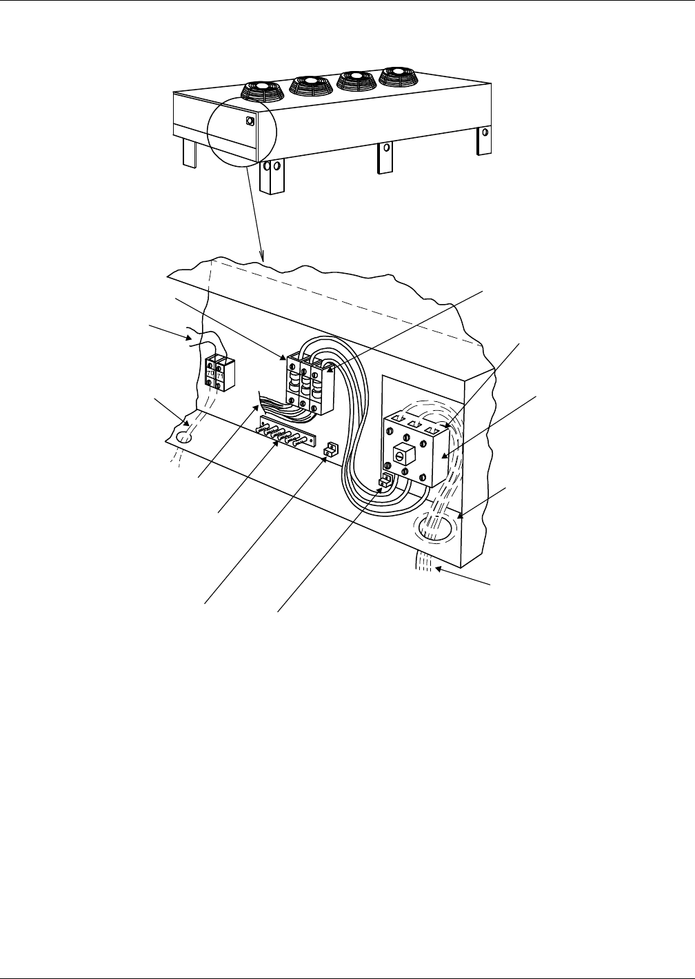
Air-Cooled Systems
Liebert® DS™72
Electrical Field Connections—Liebert Fin/Tube Condensers
Figure 60 Electrical field connections for Fan Speed Control fin/tube condensers
Earth ground connection (60Hz).
Connection terminals for field
supplied earth grounding wire
when factory disconnect is NOT
supplied.
Electric service, not by Liebert.
Single-phase for condenser
models CSF, CDF with single
fan motor. Three-phase for
all other condenser models.
DPN000666
Rev. 0
Electric service connection
terminals when factory
disconnect is NOT supplied.
Electric service connection
terminals when factory
disconnect is supplied.
Electric service entrance. A 7/8"
(22.2mm) diameter hole in a
1 1/8 in (28.6mm) knockout
provided in bottom of electric box.
Factory installed disconnect
switch (optional).
Electric service connection
and fuse block.
Factory wired to 24V
Class 2 control circuit.
Factory-wired to components
on electric panel.
Earth ground bar (optional on 50Hz only).
Connection terminals with factory
ground from each high voltage
component for field-supplied
earth grounding wire.
Earth ground connection (60Hz).
Connection terminal for field-
supplied earth grounding wire
when factory disconnect is
supplied.
Control interlock (70, 71)
Field-supplied Class 2 wiring to
interlock condenser 24V controls
to Liebert room unit;
7/8 in. (22.2mm) diameter
hole provided in bottom
of electric box.
NOTE: Refer to specification sheet for full load amp and wire size amp ratings.
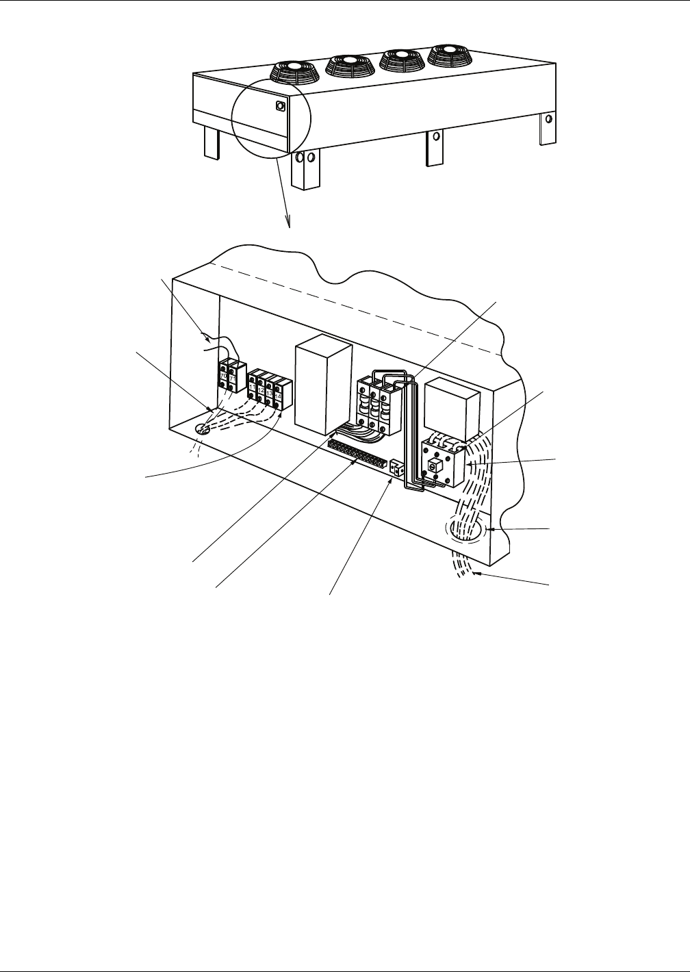
Air-Cooled Systems
73 Liebert® DS™
Figure 61 Electrical field connections for VFD control fin/tube condensers
V
F
D
SPD
Alarm Connections
Field-supplied 24V Class 1
wiring to remote alarm circuits
Surge Protection Device (SPD)
alarm contact connections (11, 12).
Variable Frequency Drive (VFD)
alarm contact connections (13, 14)
Factory-wired to 24V
control circuit.
Control interlock (70, 71)
Field-supplied
Class 1 wiring to
interlock condenser 24V
controls to Liebert
room unit; 7/8 in.
(22.2mm) diameter
hole provided in
bottom of electric box.
Factory-wired to components
on electric panel.
Earth ground bar (optional on 50Hz only).
Connection terminals with factory
ground from each high voltage
component for field-supplied
earth grounding wire.
Earth ground connection (60Hz).
Connection terminal for
field-supplied earth grounding wire
when factory disconnect is supplied.
Factory-installed fuse block on
60Hz units. Circuit breaker supplied
in lieu of fuse block on 50Hz units.
Electric service connection
terminals with factory-
supplied disconnect
Electric service entrance.
A 7/8" (22.2mm) diameter
hole in a 1-1/8 in (28.6mm)
knockout provided in bottom
of electric box.
Electric service,
not by Emerson
Factory-installed
disconnect switch
DPN001051
Rev. 1
NOTE: Refer to specification sheet for full load amp and wire size amp ratings.
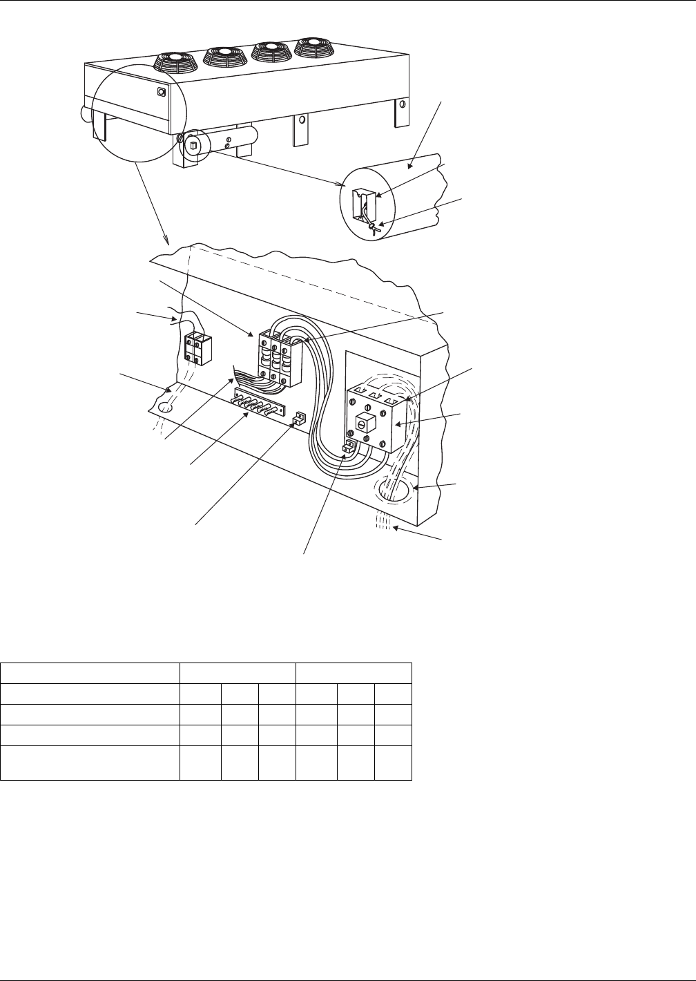
Air-Cooled Systems
Liebert® DS™74
Figure 62 Electrical field connections for Liebert Lee-Temp control fin/tube condensers
Table 53 Liebert Lee-Temp receiver electrical data, fin/tube condensers
Rated Voltage - Single Phase 120 200/208/230
Watts/Receiver 150 300 450 150 300 450
Full Load Amps 1.4 2.8 4.2 0.7 1.4 2.1
Wire Size Amps 1.8 3.5 5.3 0.9 1.8 2.7
Maximum Overcurrent
Protection Device, Amps 15 15 15 15 15 15
The Liebert Lee-Temp receiver requires a separate power feed for heaters. The condenser is not designed to supply power to the receiver.
70 71
Electric service. Three-phase for
all models. Wiring not by Emerson.
DPN000683
Rev. 0
Lee-Temp receiver tank (1 per circuit).
NOTE: Standard heater pads are 150 watts each.
(Optional 300 watt heater pads are available.)
Standard heater pad voltage is 230V. (120V
heater pad voltage is optional.)
Electrical connection box with cover.
Electrical service connection.
Pigtails in electric handy
box are factory wired to Lee-
Temp heater pads for field
connection of separate
continuous electric source,
wiring not by Emerson.
Electric service connection
terminals when factory
disconnect is NOT supplied.
Electric service connection
terminals when factory
disconnect is supplied.
Factory-installed disconnect
switch (optional).
Electric service entrance. A
7/8 in (22.2mm) diameter hole
in a 1 1/8 in (28.6mm) knockout
provided in bottom of electric box.
Earth ground connection (60Hz).
Connection terminal for field-supplied
earth grounding wire when factory disconnect
is supplied.
Earth ground connection (60Hz).
Connection terminal for field-supplied
earth grounding wire when factory
disconnect is NOT supplied.
Earth ground bar (optional on 50Hz only).
Connection terminals with factory ground
from each high-voltage component
for field-supplied earth grounding wire.
Factory-wired to components
on electric panel.
Electric service connection
and fuse block.
Factory wired to 24V
Class 2 control circuit.
Control interlock (70, 71)
Field-supplied Class 2 wiring to
interlock condenser 24V controls
to Liebert room unit;
7/8 in. (22.2mm) diameter
hole provided in bottom
of electric box.
NOTE: Refer to specification sheet for full load amp and wire size amp ratings.
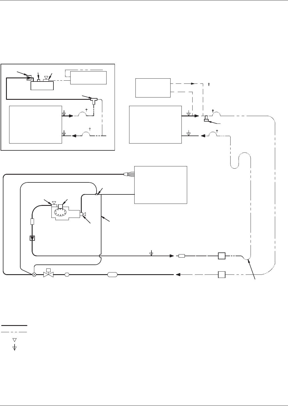
Air-Cooled Systems
75 Liebert® DS™
Piping—Fin/Tube Condensers
Typical System Configurations—Fin/Tube
Figure 64 shows a single refrigeration circuit diagram, displaying the indoor air conditioning unit,
the outdoor condenser (VFD, Fan Speed Control or Liebert Lee-Temp) and field-supplied interconnec-
tion piping.
Figure 63 Piping schematic, air-cooled with semi-hermetic compressor with fin/tube condenser
DPN000797
Rev. 6
Filter Drier
Solenoid
Valve
Expansion
Valve Sight
Glass
SUCTION
LIQUID
COMPRESSOR
EVAPORATOR
COIL
Muffler
CONDENSER
COIL
(FAN SPEED or VFD)
REFRIGERANT PIPING
FIELD PIPING
Service / Schrader (Access) Connection With Valve Core
Service / Schrader (Access) Connection No Valve Core
For rises over
25ft. (7.6m),
trap every 20ft. (6m) or
evenly divided*
NOTES: Two refrigeration circuits provided.
Single refrigeration circuit shown for clarity.
Schematic representation shown.
Do not use for specific connection locations.
CONDENSER
COIL
(Liebert Lee-Temp)
Cylinder
Unloader(s)
Sensing
Bulb
Liebert Lee-Temp Receiver
External
Equalizer
* Components are not supplied by
Emerson but are recommended for
proper circuit operation and
maintenance.
** Components supplied by Emerson
and must be field-installed (70kW,
77 kW & 105kW models only)
Service
Valve
Service
Valve
*Isolation
Valve
**Muffler
*Isolation
Valve
Liquid Return
Hot Gas Discharge
Hot Gas Discharge
LIEBERT LEE-TEMP
Inverted Trap on discharge
and liquid lines to extend above
base of coil by a minimum of
7-1/2" (190mm).
Check Valve
Check
Valve
Service
Valve
Relief Valve
Head Pressure
Control Valve
Liquid Return
Trap at base of risers
over 5ft. (1.5m)*
Optional Field-Installed
Fusible Plug
Optional
Sub-Cooling
Coil
Optional
Sub-Cooling
Coil
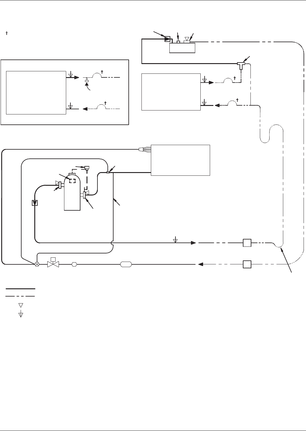
Air-Cooled Systems
Liebert® DS™76
Figure 64 Piping schematic, air-cooled with scroll or digital scroll compressor with fin/tube condenser
Inverted Trap on discharge
& liquid lines to extend above
base of coil by a minimum of
7-1/2" (190mm).
Check Valve
Check
Valve Compressor
Relief
Valve Service Valve
Service
Valve
Service
Valve
LIQUID RETURN
LIQUID RETURN
Liebert Lee-Temp Receiver Head Pressure
Control Valve
CONDENSER
COIL
(Liebert Lee-Temp)
Hot Gas
Discharge
HOT GAS DISCHARGE
* For rises over
25ft. (7.6m)
trap every 20ft.
(6m) or evenly
divided
CONDENSER
COIL
(Fan Speed or VFD)
FAN SPEED/VFD
(Liebert Lee-Temp or VFD condenser
is required with digital scroll) LIQUID
Sensing
Bulb
SUCTION
28-42kW Digital Solenoid Valve
53-70kW Digital
Solenoid Valve
Expansion
Valve
Solenoid
Valve
Sight
Glass Filter Drier
*Isolation
Valve
*Isolation
Valve Trap at base
of risers ove
r
5ft. (1.5m)
* Components are not supplied
by Emerson but are recommended
for proper circuit operation and
maintenance.
Refrigerant Piping
Field Piping
Service/Schrader (Access) Connection; No Valve Core
Service/Schrader (Access) Connection With Valve Core
DPN000798
Rev. 5
External
Equalizer
NOTES: Schematic representation shown. Do not use for specific connection locations.
Two refrigeration circuits provided. Single refrigeration circuit shown for clarity.
LIEBERT LEE-TEMP
(Liebert Lee-Temp or VFD condenser
is required with digital scroll)
EVAPORATOR
COIL
Optional field
installed fusible
plug
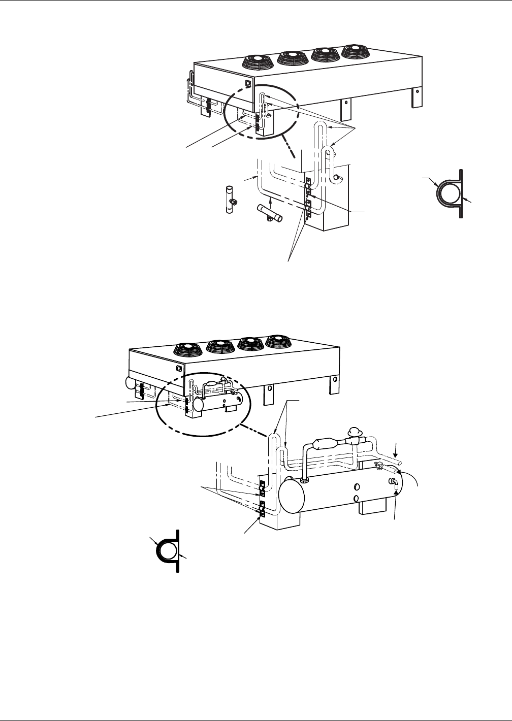
Air-Cooled Systems
77 Liebert® DS™
Figure 65 VFD and Fan Speed Control condenser piping—Fin/tube condensers
Figure 66 Liebert Lee-Temp head pressure control condenser piping—Fin/tube condensers
Fasten liquid and hot gas lines to leg using
flat surface clamps with isolators (field-supplied).
Support field piping separately to avoid coil damage
and loss of charge.
See
Detail
A-A
Inverted Traps (field-supplied)
to extend a minimum of
7-1/2" (190mm) above coil base
DPN001065
Rev. 1
Entering Hot
Gas Line
Leaving
Liquid Line
Detail A-A
Metal
Clamp
Isolator
Optional fusible plug service kit to
be brazed into the liquid line(s) in
either the vertical or horizontal
position (where required).
(Vertical position is preferable,
horizontal position is optional.)
For two-circuit systems, one
fusible plug kit must to
be installed in each circuit.
Horizontal
Vertical
Fasten liquid and hot gas lines
to leg using flat surface clamps
with isolators (field-supplied).
Support field piping separately
to avoid coil damage and loss
of charge.
Liquid
Line
Hot Gas Line
See Detail A-A
Inverted Traps (field-supplied)
to extend 8" (203mm)
above coil base
DPN000669
Rev. 2
Position elbow to direct
relief valve downward
Entering Hot
Gas Line
Leaving
Liquid
Line
Detail A-A
Metal
Clamp
Isolator
Air-Cooled Systems
Liebert® DS™78
3.12.2 Piggyback Condensers
Piggyback Selections
Table 54 Liebert DS piggyback condenser selection
Air-Cooled Condenser Selection Liebert DS Size
Condenser
Type
Ambient
Temp. °F (°C) 028 035 042 053 070 077 105
Piggyback
95 (35) PB-925 PB-925 PB-1100 PB-1350 N/A N/A N/A
100 (38) PB-1100 PB-1100 PB-1350 N/A N/A N/A N/A
105 (41) PB-1100 PB-1350 N/A N/A N/A N/A N/A
Table 55 Piggyback condenser airflow and static pressure data
Model
No.
of Fans CFM / m3 / hr
HP/RPM
Ext. Static Pressure - in. (Pa)
0.25 (62.3) 0.50 (125) 0.75 (187) 1.0 (249)
PB-350A 2 7600/12,920 2/580 3/650 3/720 3/790
PB-550A 2 6600/11,200 2/575 3/650 3/725 3/800
PB-675A 2 6900/11,730 2/605 3/680 3/750 3/820
PB-925A 2 12,500/21,250 7.5/760 7.5/810 7.5/870 7.5/920
PB-1100A 2 12,300/20,910 7.5/780 7.5/830 7.5/890 7.5/940
PB-1350A 2 16,500/28,050 10/640 10/695 10/740 15/790
Values are without filter box. External Static Pressure = filter pressure drop + other static drops.
Source: DPN000695, Rev. 0
Air-Cooled Systems
79 Liebert® DS™
Dimensions—Indoor Piggyback Condensers
Figure 67 Piggyback condenser planning dimensions
Table 56 Piggyback condenser dimensions, in. (mm)
Model A B C D E F G H J K R S
PB-350A 72
(1829)
74
(1880)
31
(787)
32
(813)
1-1/8
(29)
33
(838)
60
(1524)
8-5/8
(219)
50-3/16
(1275)
16-1/16
(408)
13-3/16
(335)
14-11/16
(373)
PB-550A 72
(1829)
74
(1880)
31
(787)
32
(813)
1-1/8
(29)
33
(838)
60
(1564)
8-5/8
(219)
50-3/16
(1275)
16-1/16
(408)
13-3/16
(335)
14-11/16
(373)
PB-675A 72
(1829)
74
(1880)
31
(787)
32
(813)
1-1/8
(29)
33
(838)
60
(1564)
8-5/8
(219)
50-3/16
(1275)
16-1/16
(408)
13-3/16
(335)
14-11/16
(373)
PB-925A 97
(2464)
99
(2515)
33
(838)
34
(864)
3-1/8
(79)
45-1/2
(1156)
85
(2159)
23-5/16
(592)
50-3/16
(1275)
16-1/16
(408)
23-1/2
(597)
14-11/16
(373)
PB-1100A 97
(2464)
99
(2515)
33
(838)
34
(864)
3-1/8
(79)
45-1/2
(1156)
85
(2159)
23-5/16
(592)
50-3/16
(1275)
16-1/16
(408)
23-1/2
(597)
14-11/16
(373)
PB-1350A 97
(2464)
99
(2515)
33
(838)
34
(864)
3-1/8
(79)
45-1/2
(1156)
85
(2159)
16-5/16
(421)
63-7/8
(1622)
19-1/8
(486)
16-13/16
(427)
11-5/8
(295)
Source: DPN000695, Rev. 0
Table 57 Piggyback condenser physical data, 60Hz
Model
Number
of Circuits
Connection Size, OD, In. Condenser Charge Per Circuit
R-407C, lb (kg)Hot Gas Liquid
PB-350 2 5/8 1/2 18 8.2)
PB-550 2 5/8 1/2 17 (7.8)
PB-675 2 7/8 1/2 25 (11.2)
PB-925 2 7/8 1/2 22 (9.9)
PB-1100 2 1-1/8 5/8 34 (15.5)
PB-1350 2 1-1/8 5/8 34 (15.5)
E
K H J
K
S
H
J
R
G
C
F
A
B D
10" (254mm)
R
Floor Level
Drain Outlet
Opening
DPN000695
Rev. 0
NOTE: A 1" (25.4mm) flange is provided on all units
for duct connection to coil duct opening and
fan air discharge opening.
UNIT DIMENSIONAL DATA
Shaded areas
indicate a recommended
clearance of 34" (864mm)
for component access.
Fan Discharge
Optional Fan
Discharge
Disconnect
Switch (optional)
FLOOR CUTOUT DIMENSIONS
1" (25.4mm)
A
Unit Base
C
Unit Base
72"
(1829mm)
Overall Dimensions
Overall Dimensions
5"
(127mm)
35-1/8"
(892mm)
1-1/8"
(29mm)
Condenser Coil Inlet
And Duct Connection

Air-Cooled Systems
Liebert® DS™80
Electrical Data—Piggyback Condensers
Electrical Field Connections—Liebert Piggyback Condensers
Figure 68 Electrical field connections for Liebert piggyback condensers
Table 58 Piggyback condenser electrical data, 60 Hz, 3 phase 1
hp
208 230 460 575
FLA LRA FLA LRA FLA LRA FLA LRA
2.0 7.5 51.0 6.8 44.0 3.4 22.0 2.7 17.6
3.0 10.6 73.6 9.6 64.0 4.8 32.0 3.9 25.6
5.0 16.7 106.0 15.2 88.0 7.6 44.0 6.1 35.2
7.5 25.3 129.4 22.0 111.4 11.0 55.7 9.0 44.8
10.0 30.8 186.0 28.0 162.0 14.0 84.0 11.0 66.0
15.0 46.2 267.0 42.0 225.0 21.0 116.0 17.0 93.0
1. See Table 59 for separate power feed needed for Lee-Temp receiver heaters.
2. FLA: Full Load Amps; LRA: Lock Rotor Amps
3. Source: DPN000695, Rev. 0
7
1
70
90
91
DPN000697
Rev. 0
Factory-installed unit disconnect switch (optional)
Field-supplied disconnect switch
when factory-installed unit disconnect
switch is not provided.
Three phase electric
service not by
Emerson
Three-phase connection. Electric
service connection terminals
when factory disconnect switch
is supplied
Factory-installed disconnect
switch (optional)
Electric conduit knockouts
on bottom of wire raceway
Knockout sizes 1-3/8"
(34.9mm) or 1-3/4" (44.5mm)
or 2 1/2" (63.5mm)
Three-phase electric service not by
Emerson
Earth ground connection (60Hz).
Connection terminal for field-supplied
earth grounding wire.
Control interlock Field-supplied, Class 2 wiring to
Terminals 70 & 71 to interlock condenser 24V
controls to Liebert room unit; 7/8 in. (22.2mm)
diameter knockout provided in bottom of box
Factory-wired to components
on electric panel
Refer to specification sheet for full load amp and wire size amp ratings.
Liebert Lee-Temp electric
service connection to terminals
supplied from factory-wired
Liebert Lee-Temp heater pads
for field connection of separate
continuous electrical source,
not supplied by Emerson.
Factory-wired to components
on electric panel.
Three-phase connection. Electric service
connection terminals when factory
disconnect switch is not supplied
Air-Cooled Systems
81 Liebert® DS™
Figure 69 Electrical field connections for Liebert piggyback condensers
Table 59 Separate electrical supply requirements for Liebert Lee-Temp™ receivers, 60Hz, 1 Ph
Voltage 120 120 208/230 208/230
Watts/Receiver 150 300 150 300
FLA 2.5 5.0 1.4 2.8
WSA 3.1 6.2 1.8 3.6
OPD 15 15 15 15
Only one independent input power supply is needed per piggyback unit; connect to Terminals 90 & 91.
7
1
70
90
91
DPN000697
Rev. 0
Factory-installed unit disconnect switch (optional)
Field-supplied disconnect switch
when factory-installed unit disconnect
switch is not provided.
Three phase electric
service not by
Emerson
Three-phase connection. Electric
service connection terminals
when factory disconnect switch
is supplied
Factory-installed disconnect
switch (optional)
Electric conduit knockouts
on bottom of wire raceway
Knockout sizes 1-3/8"
(34.9mm) or 1-3/4" (44.5mm)
or 2 1/2" (63.5mm)
Three-phase electric service not by
Emerson
Earth ground connection (60Hz).
Connection terminal for field-supplied
earth grounding wire.
Control interlock Field-supplied, Class 2 wiring to
Terminals 70 & 71 to interlock condenser 24V
controls to Liebert room unit; 7/8 in. (22.2mm)
diameter knockout provided in bottom of box
Factory-wired to components
on electric panel
Refer to specification sheet for full load amp and wire size amp ratings.
Liebert Lee-Temp electric
service connection to terminals
supplied from factory-wired
Liebert Lee-Temp heater pads
for field connection of separate
continuous electrical source,
not supplied by Emerson.
Factory-wired to components
on electric panel.
Three-phase connection. Electric service
connection terminals when factory
disconnect switch is not supplied
Air-Cooled Systems
Liebert® DS™82
Figure 70 Piggyback condenser piping and electrical connection locations
Table 60 Dimensions—Piggyback condensers, in. (mm)
Model A B C D E F G
PB-350A — — 27-1/4 (692) 2-1/2 (64) 6 (152) 10-1/8 (267) 28-3/4 (730)
PB-550A — — 27-1/4 (692) 2-1/2 (64) 6 (152) 10-1/8 (267) 28-3/4 (730)
PB-675A — — 27-1/4 (692) 2-1/2 (64) 6 (152) 10-1/8 (267) 28-3/4 (730)
PB-925A — — 27-1/4 (692) 2-1/2 (64) 6 (152) 10-1/8 (267) 28-3/4 (730)
PB-1100A — — 27-1/4 (692) 2-1/2 (64) 6 (152) 10-1/8 (267) 28-3/4 (730)
PB-1350A 11-1/4 (286) 24 (610) 26-1/2 (673) 7 (178) 6 (152) — —
Table 61 Piping connection sizes, ODS, in. (mm)
Model Liquid Line Hot Gas Line Drain
PB-350A 2 @ 1/2 (13) 2 @ 5/8 (16) 1-1/4 (32)
PB-550A 2 @ 1/2 (13) 2 @ 5/8 (16) 1-1/4 (32)
PB-675A 2 @ 1/2 (13) 2 @ 7/8 (22) 1-1/4 (32)
PB-925A 2 @ 1/2 (13) 2 @ 7/8 (22) 1-1/4 (32)
PB-1100A 2 @ 5/8 (16) 2 @ 1-1/8 (29) 1-1/4 (32)
PB-1350A 2 @ 5/8 (16) 2 @ 1-1/8 (29) 1-1/4 (32)
8"
(203mm)
E
E
D
C
A
F
D
E
G
C
B
"
E
1. Multiple knockouts of 1-3/8" (35mm), 1-3/4" (45mm) and 2-1/2" (64mm) for main power supply (typical).
2. 7/8" (22.2mm) knockouts for Liebert Lee-Temp power supply (typical).
3. Cover plate for access of liquid line and hot gas line.
MODELS PB-350A THRU PB-1100A
ALL MODELS
MODEL PB-1350A
DPN00696
Rev. 1
See Note 2
See Note 1
See Note 2 See Note 2
See Note 2
See Note 1 See Note 1
See Note 2
See Note 1
7-7/8"
(200mm) 7-7/8"
(200mm)
3" (76mm)
3"
(76mm)
3"
(76mm)
3" (76mm)
3" (76mm)
3" (76mm)
3" (76mm)
3" (76mm)
1" (25mm)
Panel 1" (25mm)
Panel
1-13/16"
(46mm)
1-13/16"
(46mm)
See Note 3
See Note 3
See Note 3 See Note 3
1-1/2"
(38mm)
12-5/8"
(321mm) 12-5/8"
(321mm)
4-1/2" (114mm) 4-1/2"
(114mm)
9-11/16"
(246mm) 9-11/16"
(246mm)
Drain Outlet
Location
1-1/4" (32mm) F.P.T.
3-1/4" (85mm) See Note 2
6"
(152mm)
5-1/2" (140mm) See Note 1
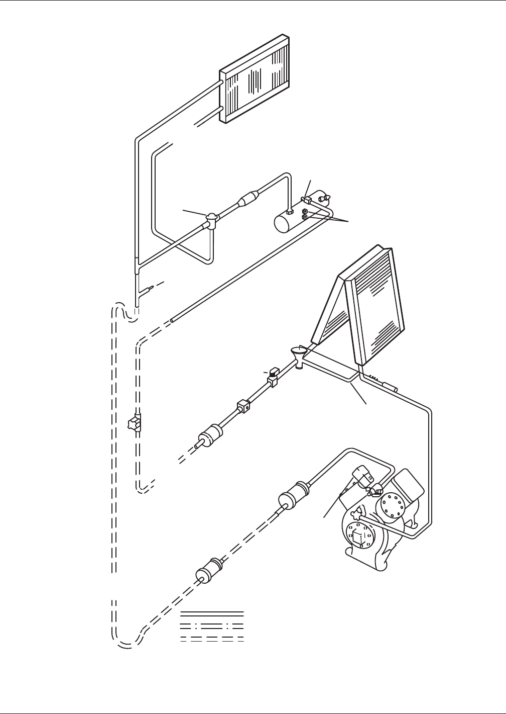
Air-Cooled Systems
83 Liebert® DS™
Figure 71 Piping schematic—Liebert DS with piggyback condenser and Liebert Lee-Temp™
DPN000692
Rev. 0
Sight
Glass
Evaporator
Coil
* Shutoff
Valve
Filter
Dryer
Solenoid
Valve
Expansion
Valve
Sensing Bulb
External
Equalizer
Service
Valves
Compressor
SINGLE CIRCUIT SHOWN
Hot Gas
Discharge
FACTORY PIPING
OPTIONAL PIPING
FIELD PIPING
* Components are not supplied by Emerson
but are recommended for proper
circuit operation and maintenance
** Components supplied by Emerson
and must be field-installed.
Muffler
Condenser Coil
Check
Valve
Head Pressure
Control with
Integral Check
Valve
Liebert
Lee-Temp
Receiver
Rotalock Valve
Liquid Return from
Condenser Coil
Service
Valve
Pressure
Relief Valve
* Traps
every
25 ft.
(7.6m)
of Rise
* * Muffler
Double discharge risers
are required wWhen unit
is operating below 30%
of full capacity. Consult
factory for proper selection.
Liquid
Return
to Unit
Sight Glasses
Cylinder
Unloaders
(Optional)
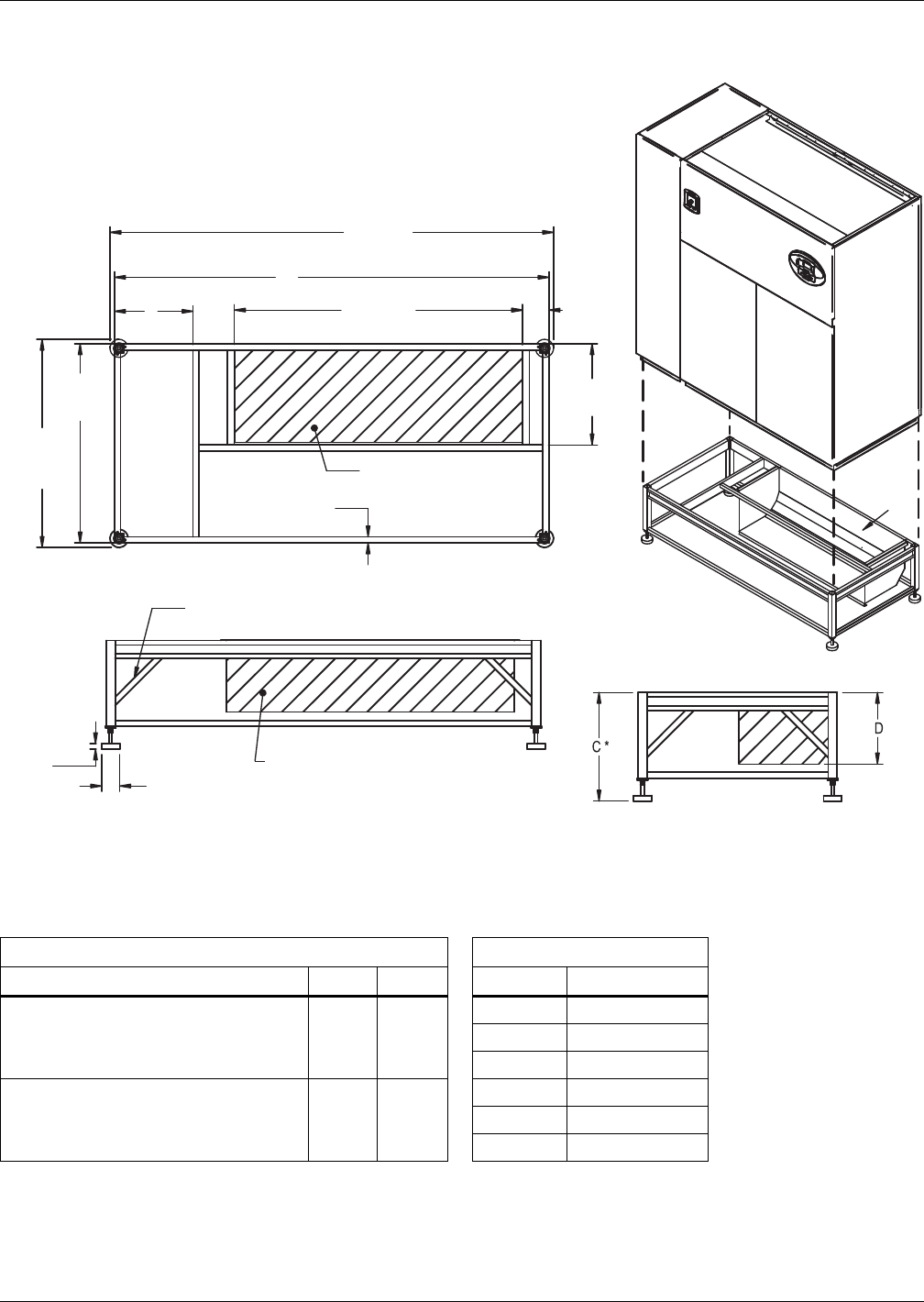
Air-Cooled Systems
Liebert® DS™84
3.13 ANCILLARY ITEMS—AIR-COOLED SYSTEMS
Figure 72 Floor stand dimensions—28-42kW (8-12 ton), downflow
Table 62 Floor stand and floor planning dimensions—28-42kW (8-12 ton), downflow
Dimensional Data, in. (mm) Height, in. (mm)
Model A B C* D turning vane
Air-Cooled Semi-Hermetic Models and
All Water/Glycol/GLYCOOL Models
85
(2159)
26
(660)
9 (229) 4 (111)
12 (305) 7 (187)
15 (381) 10 (264)
Air-Cooled Scroll Models and
Air-Cooled Digital Scroll Models
72
(1829)
13
(330)
18 (457) 13 (340)
21 (533) 16 (416)
24 (610) 19 (492)
Source: DPN000820, Rev. 3
DPN000820
Rev. 3
NOTE: Right side of paneled unit is flush with right side of floorstand. All other paneled sides overhang
floor stand 1" (25mm).
* Leveling feet are provided with ± 1-1/2" (38mm) adjustment from nominal height C.
Gussets supplied on floor stands
12" (305 mm) tall and greater
Turning vane air outlet
Optional turning vane can be field-installed
in supply air discharge opening for front or
rear air discharge.
Supply air
discharge
opening
Optional turning vane
shown as front air discharge.
Supply air
discharge opening
33"
(838mm)
47-15/16"
(1218mm)
34-1/2"
(876mm)
(with feet)
A+1-1/2"
(38mm) (with feet)
16-3/4"
(425mm)
1"
(25mm) TYP.
3"
(76mm)
7/8"
(23mm)
4-1/2"
(114mm)
A
B
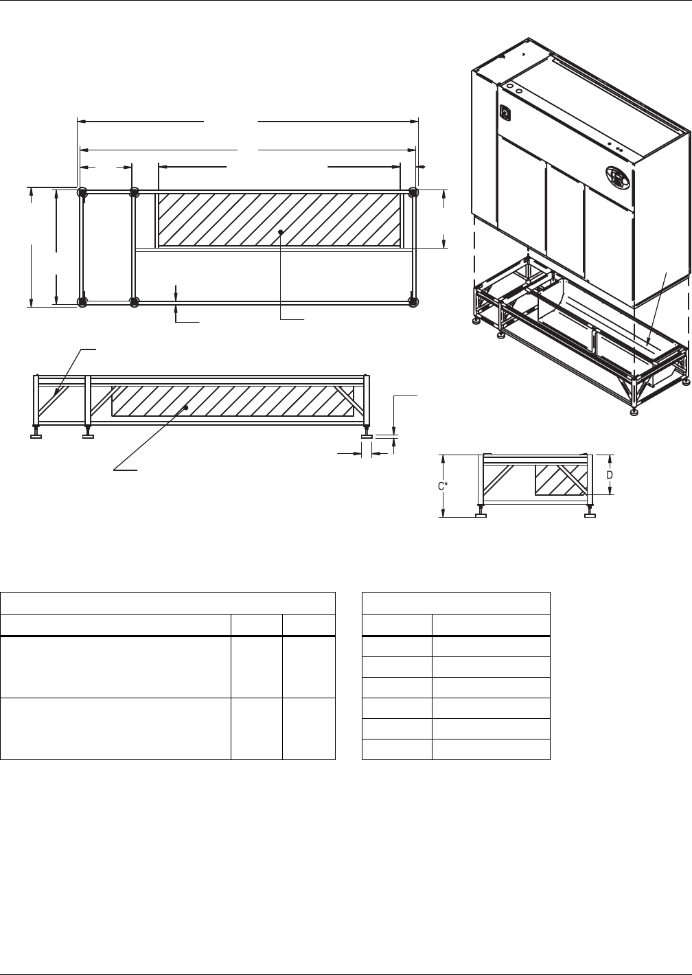
Air-Cooled Systems
85 Liebert® DS™
Figure 73 Floor stand dimensions—53-77kW (15-22 ton), downflow
Table 63 Floor stand and floor planning dimensions—53-77kW (15-22 ton), downflow
Dimensional Data, in. (mm) Height, in. (mm)
Model A B C* D - Turning Vane
Air-Cooled Semi-Hermetic Models and
All Water/Glycol/GLYCOOL Models
108
(2743)
26
(660)
9 (229) 4 (111)
12 (305) 7 (187)
15 (381) 10 (264)
Air-Cooled Scroll Models and
Air-Cooled Digital Scroll Models
97
(2464)
15
(381)
18 (457) 13 (340)
21 (533) 16 (416)
24 (610) 19 (492)
Source: DPN000930, Rev. 2
DPN000930
Rev. 2
NOTE: Right side of paneled unit is flush with right side of floor stand. All other paneled sides overhang
floor stand 1" (25mm). * Leveling feet are provided with ± 1-1/2" (38mm) adjustment from nominal height C.
Gussets supplied on floor stands
12" (305 mm) tall and greater
Turning vane air outlet
Optional turning vane can be field-installed
in supply air discharge opening for front or
rear air discharge.
Supply air
discharge
opening
Optional turning vane
shown as front air discharge.
Supply air
discharge opening
34-1/2"
(876mm)
(with feet)
A+1-1/2"
(38mm) (with feet)
33"
(838mm)
69-3/4" (1772mm)
16-3/4"
(425mm)
1"
(25mm) TYP.
3"
(76mm)
7/8"
(23mm)
A
B
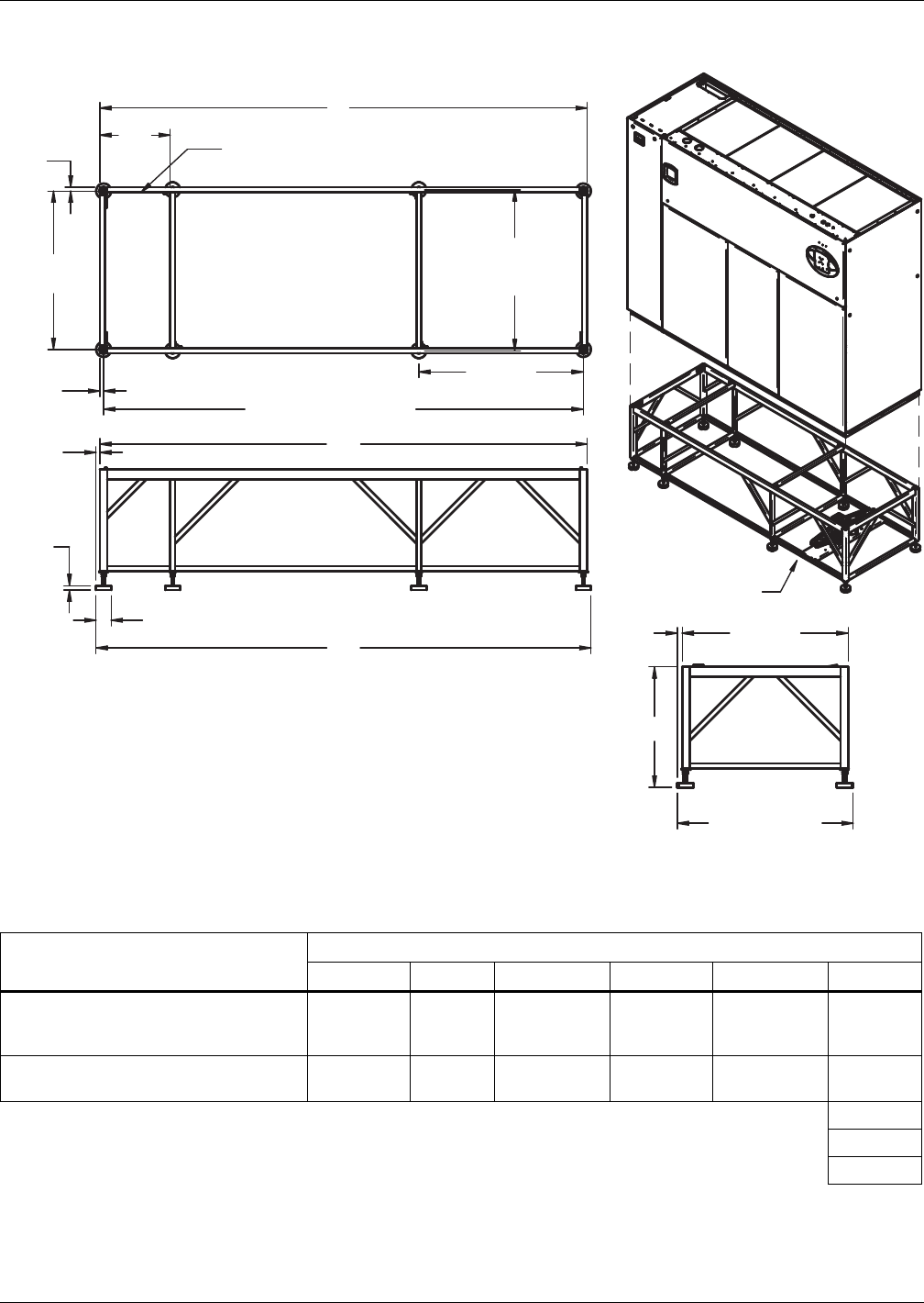
Air-Cooled Systems
Liebert® DS™86
Figure 74 Floor stand and floor planning dimension, downflow 53-77kW (15-22 tons) models with EC
fans
Table 64 Floor stand and floor planning dimensions—53-77kW (15-22 ton), downflow with EC fans
Liebert DS Model
Dimensional Data in (mm)
AB C D E F
DS053-077, Air-Cooled Semi-Hermetic
and all Water/Glycol/ GLYCOOL
Models
108 (2743) 26 (660) 106.5 (2705) 108 (2743) 109.5 (2781) 24 (610)
DS053-077, Air-Cooled Scroll and
Air-Cooled Digital Scroll Models 97 (2464) 15 (381) 5.5 (2426) 97 (2464) 98.5 (2502) 30 (762)
Source: DPN002151, Rev. 1 36 (914)
42 (1067)
48 (1219)
B
F *
D
E
A
Piping Access Area
See Note 4
32"
(813mm)
Center Feet
C
Support Feet Centers
3/4"
(19mm)
3/4"
(19mm)
3/4"
(19mm)
31-1/2"
(800mm)
1"
(25mm)
33"
(838mm)
35"
(889mm)
Overall Depth
7/8"
(23mm)
3"
(76mm)
32-3/4"
(832mm)
DPN002151
Rev. 1
1. This floor stand should be used when EC fans are intended to be lowered under
a raised floor. The standard Liebert DS floor stand can be used if the fans are to
remain in their original raised position.
2. Right side of paneled unit is flush with right side of floor stand. All other paneled sides
overhang floor stand 1" (25mm).
3) The floor stand used with EC units is not symmetrical and its orientation to the
Liebert DSE is critical for lowering the EC fans. Unless the floor stand is installed in
the correct position, the blowers will not lower into the floor stand.
4. Jack and jack support are shipped loose and are intended to be placed into position
under each fan and utilized to lower or raise that fan as needed.
* Leveling feet are provided with ±1-1/2" (38mm) adjustment from nominal height C.
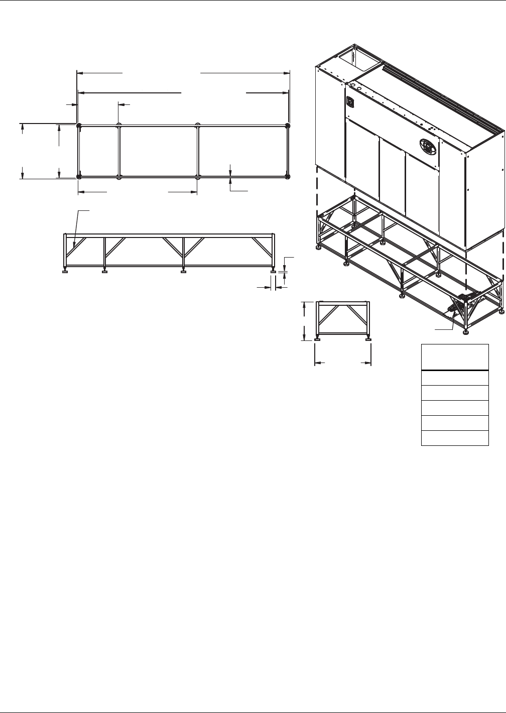
Air-Cooled Systems
87 Liebert® DS™
Figure 75 Floor stand and floor planning dimensions—downflow 105kW (30 ton) models with EC fans,
standard scroll and semi-hermetic compressors without turning vane
74" (1880mm)
Gussets supplied on floor stands
12" (305mm) tall and greater.
3"
(76mm)
See Note 4
33"
(838mm)
34-1/2"
(876mm)
(with feet)
132-1/2" (3366mm)
(with feet)
25"
(635mm)
131" (3327mm)
1"
(25mm Typ.)
35"
(889mm)
Overall
Depth
A*
DPN002152
Rev. 1
NOTE:
1) This floor stand should be used when EC fans are intended
to be lowered under a raised floor. The standard Liebert DS
floor stand can be used if the fans are to remain in their
original raised position.
2) Right side of paneled unit is flush with right side of floor stand.
All other paneled sides overhang floor stand 1" (25mm).
3) The floor stand used with EC units is not symmetrical and
its orientation to the Liebert DS is critical for lowering the EC fans.
Unless the floor stand is installed in the correct position,
the blowers will not lower into the floor stand.
4) Jack and jack support are shipped loose and are intended
to be placed into position under each fan and utilized to lower
or raise that fan as needed.
*Leveling feet are provided with ± 1-1/2" (38mm) adjustment from nominal height “A”.
Height - A
in. (mm)
24 (610)
30 (762)
36 (914)
42 (1067)
48 (1219)
Digital scroll compressors
not available on 105 models.
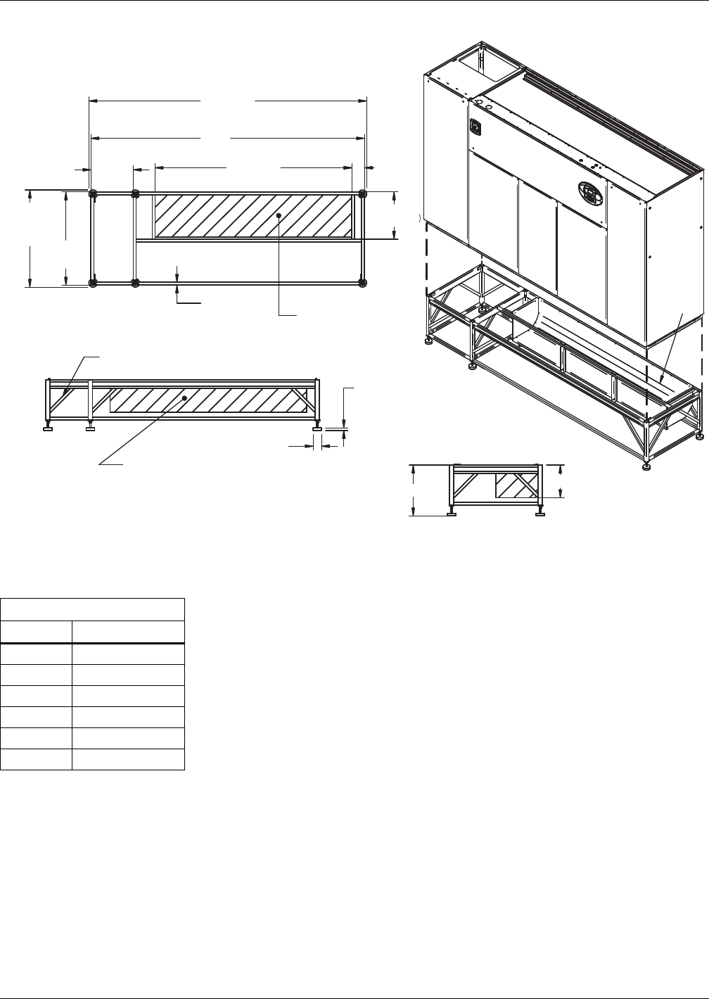
Air-Cooled Systems
Liebert® DS™88
Figure 76 Floor stand dimensions—105kW (30 ton), downflow with turning vane and centrifugal fans
Table 65 Floor stand and floor planning dimensions—105kW (30 ton), downflow
Height, in. (mm)
C* D Turning Vane
9 (229) 4 (111)
12 (305) 7 (187)
15 (381) 10 (264)
18 (457) 13 (340)
21 (533) 16 (416)
24 (610) 19 (492)
Source: DPN001059, Rev. 2
D
DPN001059
Rev. 2
NOTE: Right side of paneled unit is flush with right side of floorstand. All other paneled sides overhang
floor stand 1" (25mm).
* Leveling feet are provided with ± 1-1/2" (38mm) adjustment from nominal height C.
Gussets supplied on floor stands
12" (305 mm) tall and greater
Turning vane air outlet
Optional turning vane can be field-installed
in supply air discharge opening for front or
rear air discharge.
Supply air
discharge
opening
Optional turning vane
shown as front air discharge.
Supply air
discharge opening
33"
(838mm)
34-1/2"
(876mm)
(with feet)
132-1/2"
(3366mm) (with feet)
26"
(660mm) 91-3/4"
(2330mm)
131"
(3327mm)
16-3/4"
(425mm)
1"
(25mm) TYP.
3"
(76mm)
7/8"
(23mm)
4-1/2"
(114mm)
C*
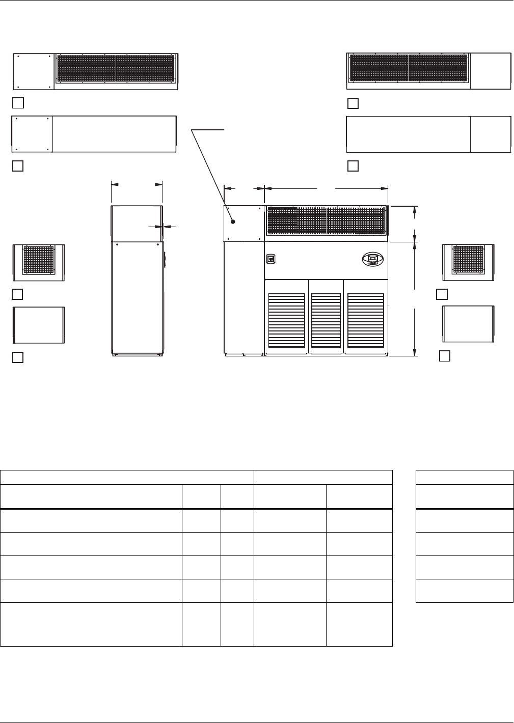
Air-Cooled Systems
89 Liebert® DS™
Figure 77 Plenum dimensions—28-105kW (8-30 ton), upflow
Table 66 Plenum dimensions, in. (mm)—28-105kW (8-30 ton), upflow
Dimensions, in. (mm) Grille Size, in (mm) - Nominal Height, in. (mm)
Model A B
Front/Rear
Grilles Side Grille H
28-42kW (8-12 ton) Air-Cooled Scroll and
Air-Cooled Digital Scroll Models
59-1/4
(1505)
13-3/4
(349)
18 x 55
(457 x 1397)
18 x 20
(457 x 508) 20 (508)
28-42kW (8-12 ton) Semi-Hermetic and
all Water/Glycol/GLYCOOL Models
59-1/4
(1505)
26-3/4
(679)
18 x 55
(457 x 1397)
18 x 20
(457 x 508) 24 (610)
53-77kW (15-22 ton) Air-Cooled Scroll and
Air-Cooled Digital Scroll Models
82-1/4
(2089)
15-3/4
(400)
18 x 78
(457 x 1981)
18 x 20
(457 x 508) 30 (762)
53-77kW (15-22 ton) Semi-Hermetic and
all Water/Glycol/GLYCOOL Models
82-1/4
(2089)
26-3/4
(679)
18 x 78
(457 x 1981)
18 x 20
(457 x 508) 36 (914)
105kW (30 ton)—All Models 105-1/4
(2673)
26-3/4
(679)
(1) 18 x 20
(457 x 508)
(1) 18 x 78
(457 x 1981)
18 x 20
(457 x 508)
Source: DPN001187, Rev. 1
WITH GRILLE
B A
H
WITHOUT GRILLE
FRONT VIEWS
WITH GRILLE
WITHOUT GRILLE
REAR VIEWS
Panel removable
for condenser clean
out access
(Water/Glycol/GLYCOOL
models only)
RIGHT SIDE VIEWS -
CHECK ONE (1):
WITH GRILLE
WITHOUT
GRILLE
FRONT VIEW - UNIT WITH PLENUM
SIDE VIEW - UNIT WITH PLENUM
WITH GRILLE
WITHOUT
GRILLE
Notes:
1. Typical 53-77kW (15-22 Tons) unit orientation shown with grille Plenum.
View varies by unit size and Plenum selection.
2. All Plenums are shipped flat and must be field assembled.
3. Optional grille Plenum kits must include front or rear grille.
4. Non-grille Plenums are open on the top and not designed with duct flange.
LEFT SIDE VIEWS -
CHECK ONE (1):
34"
(864mm)
1"
(25mm)
76"
(1930mm)
DPN001187
Rev. 1
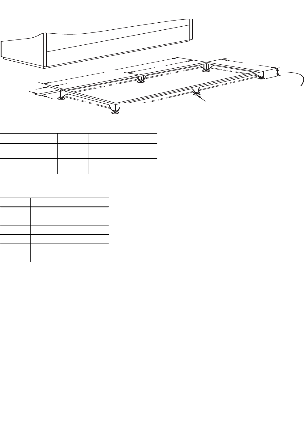
Air-Cooled Systems
Liebert® DS™90
Figure 78 Floor stand dimensions, piggyback condensers with centrifugal fans
Table 67 Floor stand dimensions, in. (mm)
Model ABC
PB-350A, PB-550A
PB-675A 72 (1829) 36 (914) 31 (787)
PB-925A, PB-1100A
PB-1350A 97 (2464) 48-1/2 (1232) 33 (838)
Source: DPN000727, Rev. 0
Table 68 Floor stand height selection, in. (mm)
Nominal Range (Nominal ±1-1/2 *)
9 (229) 7-1/2 to 10-1/2 (191 to 267)
12 (305) 10-1/2 to 13-1/2 (267 to 343)
15 (381) 13-1/2 to 16-1/2 (343 to 419)
18 (458) 16-1/2 to 19-1/2 (419 to 495)
21 (553) 19-1/2 to 22-1/2 (495 to 572)
24 (610) 22-1/2 to 25-1/2 (572 to 648)
Leveling feet are provided with ±1-1/2" (38mm)
Adjustment from nominal height "H".
Source: DPN000727, Rev. 0
A
BC
1"
(25.4mm)
Center Leg Provided
on 99" Cabinets
Leg Support on Models
18, 21 & 24" High
* H ± 1-1/2" (38mm)
For height selection
refer to chart.
DPN000727
Rev. 0
See Table 68 for
height selection
Water-Cooled, Glycol-Cooled and GLYCOOL Systems
91 Liebert® DS™
4.0 WATER-COOLED, GLYCOL-COOLED AND GLYCOOL SYSTEMS
4.1 CAPACITY AND PHYSICAL DATA
Table 69 Performance data—Water-cooled, EC fans
Model Size 28 35 42 053 070 077 105
CAPACITY DATA WITH EC FANS
Net Capacity Data kW (BTUH), Standard Air Volume and Evaporator Fan Motor
Semi Hermetic Compressors with EC Fans
85°F DB, 64.5°F WB, 52.3°F DP (29.4°C DB, 18.1°C WB) 32.4% RH
Total kW (kBTUH) 42.1 (143.8) 38.7 (132) 50.1 (171) 65.1 (220) 78.6 (268.3) 87.1 (297.1) 112.1 (382.3)
Sensible kW (kBTUH) 39.6 (135) 31.7 (108.2) 48.9 (166.9) 63.4 (212.9) 75.7 (258.2) 83.6 (285.4) 103.9 (354.6)
80°F DB, 62.9°F WB, 52.3°F DP (26.7°C DB, 17.1°C WB) 38.2% RH
Total kW (kBTUH) 40.5 (138.1) 39.7 (135.4) 47.9 (163.4) 62.2 (212.1) 75.3 (256.9) 83.4 (284.7) 107.8 (367.7)
Sensible kW (kBTUH) 35.9 (122.4) 34.4 (117.3) 44.4 (151.4) 58 (197.7) 68.9 (235) 76 (259.5) 94.3 (321.9)
75°F DB, 61.1°F WB, 52.3°F DP (23.9°C DB, 16.2°C WB) 45.1% RH
Total kW (kBTUH) 38.9 (132.7) 41.4 (141.4) 45.9 (156.7) 59.4 (202.6) 72 (245.8) 80 (273) 103.4 (352.9)
Sensible kW (kBTUH) 32 (109.3) 38.7 (131.9) 39.5 (134.7) 51.7 (176.4) 61.2 (209) 67.6 (230.8) 83.7 (285.7)
72°F DB, 60.0°F WB, 52.3°F DP (22.2°C DB, 15.6°C WB) 49.9% RH
Total kW (kBTUH) 38 (129.6) 43.5 (43.5) 44.8 (152.9) 57.8 (197.2) 70.2 (239.6) 78 (266.2) 101 (344.6)
Sensible kW (kBTUH) 29.7 (101.4) 42.6 (42.6) 36.4 (124.3) 47.7 (162.8) 56.5 (192.9) 62.4 (212.8) 77.5 (264.3)
Net Capacity Data kW (BTUH), Standard Air Volume and Evaporator Fan Motor
Scroll or Digital Scroll Compressors with EC Fans
Scroll Compressors
Only
85°F DB, 64.5°F WB, 52.3°F DP (29.4°C DB, 18.1°C WB) 32.4% RH
Total kW (kBTUH) 35.2 (120) 42 (143.3) 47.5 (162.1) 66.3 (224.1) 80.8 (275.6) 88.5 (301.9) 111.3 (379.9)
Sensible kW (kBTUH) 35.1 (119.9) 41.6 (142.1) 47.2 (161) 64.3 (215.6) 77 (262.6) 84.5 (288.3) 103.6 (353.4)
80°F DB, 62.9°F WB, 52.3°F DP (26.7°C DB, 17.1°C WB) 38.2% RH
Total kW (kBTUH) 34 (116.1) 40.1 (136.7) 45.4 (154.8) 63.3 (216.1) 77.5 (264.6) 85 (290.2) 107.2 (365.9)
Sensible kW (kBTUH) 32.5 (111) 37.9 (129.4) 43.1 (147) 58.6 (200.1) 70 (238.9) 76.9 (262.3) 94.1 (321.1)
75°F DB, 61.1°F WB, 52.3°F DP (23.9°C DB, 16.2°C WB) 45.1% RH
Total kW (kBTUH) 32.8 (111.8) 38.4 (131) 43.5 (148.4) 60.5 (206.5) 74.3 (253.5) 81.8 (279.1) 103.2 (352.2)
Sensible kW (kBTUH) 29.1 (99.2) 33.8 (115.2) 38.4 (130.9) 52.2 (178.3) 62.3 (212.7) 68.5 (233.6) 83.8 (285.9)
72°F DB, 60.0°F WB, 52.3°F DP (22.2°C DB, 15.6°C WB) 49.9% RH
Total kW (kBTUH) 32 (109.2) 37.5 (127.9) 42.5 (145) 58.9 (201.1) 72.5 (247.5) 79.9 (272.6) 100.9 (344.2)
Sensible kW (kBTUH) 26.8 (91.6) 31.2 (106.3) 35.4 (120.7) 48.3 (164.7) 57.7 (196.7) 63.2 (215.6) 77.5 (264.4)
FAN SECTION - Downflow Models - EC Fans Under Floor
Standard Air Volume, CFM (CMH)
0.2" external static 4,400 (7,476) 5,200 (8,835) 6200
(10534)
8,000
(13,592)
9,600
(16,310)
11,000
(18,689)
13700
(23276)
Standard Fan Motor, Nominal kW
(total for all fans) 2.8 2.8 2.8 2.5 4.0 5.9 7.8
Number of Fans 1 1 1 2 2 2 3
1. Canister humidifier not available with EC fans.
2. Capacity data is rated and factory certified per ASHRAE 127-2012 with a 5% tolerance.
3. Some options or combinations of options may result in reduced air flow—consult factory for recommendations.
4. Digital scroll not available on 077 and 105 models; units available with semi-hermetic and standard scroll compressors only
Water-Cooled, Glycol-Cooled and GLYCOOL Systems
Liebert® DS™92
Table 70 Performance data—Water-cooled units with centrifugal fans
Model Size 28 35 42 053 070 077 105
CAPACITY DATA WITH CENTRIFUGAL FANS
Net Capacity Data kW (BTUH), Standard Air Volume and Evaporator Fan Motor
Semi-Hermetic Compressors with Centrifugal Fans
85°F DB, 64.5°F WB, 52.3°F DP (29.4°C DB, 18.1°C WB) 32.4% RH
Total kW (kBTUH) 41.5 (141.6) 42.4 (144.7) 48.4 (165.2) 62.1 (211.9) 76.9 (262.5) 85.0 (289.9) 110.3 (376.4)
Sensible kW (kBTUH) 38.9 (132.8) 41.6 (141.9) 47.4 (161.7) 57 (194.6) 72.8 (248.4) 80.4 (274.4) 102.2 (348.7)
80°F DB, 62.9°F WB, 52.3°F DP (26.7°C DB, 17.1°C WB) 38.2% RH
Total kW (kBTUH) 39.8 (135.9) 40.4 (137.9) 46.1 (157.4) 59.7 (205.2) 73.7 (251.6) 81.5 (278.1) 106 (361.8)
Sensible kW (kBTUH) 35.2 (120.2) 37.6 (128.3) 42.8 (146.1) 51.9 (180.6) 66.1 (225.5) 72.9 (248.8) 92.6 (315.9)
75°F DB, 61.1°F WB, 52.3°F DP (23.9°C DB, 16.2°C WB) 45.1% RH
Total kW (kBTUH) 38.3 (130.5) 38.6 (131.9) 44.2 (150.7) 57.2 (196.9) 70.6 (240.8) 78.2 (266.7) 101.7 (346.9)
Sensible kW (kBTUH) 31.4 (107.1) 33.3 (113.8) 37.9 (129.3) 46.4 (162.1) 58.7 (200.3) 64.7 (220.8) 82 (279.8)
72°F DB, 60.0°F WB, 52.3°F DP (22.2°C DB, 15.6°C WB) 49.9% RH
Total kW (kBTUH) 37.3 (127.4) 37.7 (128.5) 43.1 (146.9) 55.8 (191.9) 68.8 (234.7) 76.2 (260.1) 99.2 (338.6)
Sensible kW (kBTUH) 29.1 (99.2) 30.7 (104.7) 34.8 (118.8) 43 (150.6) 54.2 (184.9) 59.6 (203.5) 75.7 (258.4)
Net Capacity Data kW (BTUH), Standard Air Volume and Evaporator Fan Motor
Scroll or Digital Scroll Compressors with Centrifugal Fans
Scroll Compressors
Only
85°F DB, 64.5°F WB, 52.3°F DP (29.4°C DB, 18.1°C WB) 32.4% RH
Total kW (kBTUH) 34.5 (117.8) 40.9 (139.7) 45.8 (156.3) 64.9 (219.6) 79.0 (269.6) 86.5 (295.1) 109.6 (374)
Sensible kW (kBTUH) 34.5 (117.7) 40.6 (138.5) 45.6 (155.5) 62.0 (207.9) 74.0 (252.5) 81.3 (277.3) 101.8 (347.5)
80°F DB, 62.9°F WB, 52.3°F DP (26.7°C DB, 17.1°C WB) 38.2% RH
Total kW (kBTUH) 33.4 (113.9) 39.0 (133.2) 43.6 (148.8) 62.2 (212.1) 75.9 (259.1) 83.1 (283.6) 105.5 (360)
Sensible kW (kBTUH) 31.9 (108.8) 36.9 (125.8) 41.5 (141.6) 56.4 (192.6) 67.2 (229.3) 73.7 (251.5) 92.4 (315.2)
75°F DB, 61.1°F WB, 52.3°F DP (23.9°C DB, 16.2°C WB) 45% RH
Total kW (kBTUH) 32.1 (109.6) 37.4 (127.5) 41.7 (142.3) 59.5 (202.9) 72.8 (248.5) 80 (272.9) 101.5 (346.3)
Sensible kW (kBTUH) 28.4 (97) 32.7 (111.7) 36.8 (125.5) 50.3 (171.5) 59.8 (203.9) 65.5 (223.7) 82.1 (280)
72°F DB, 60.0°F WB, 52.3°F DP (22.2°C DB, 15.6°C WB) 49.9% RH
Total kW (kBTUH) 31.4 (107) 36.5 (124.4) 40.7 (138.9) 57.9 (197.5) 71.1 (242.6) 78.1 (266.5) 99.1 (338.3)
Sensible kW (kBTUH) 26.2 (89.4) 30.1 (102.8) 33.8 (115.2) 46.4 (158.4) 55.3 (188.6) 60.5 (206.4) 75.8 (258.5)
FAN SECTION - Downflow Models - Fixed Pitch, Two Belts
Standard Air Volume,
CFM (CMH)
0.2" external static
4,400 (7,476) 5,200 (8,835) 6200 (10534) 7,500 (12,743) 9,000 (15,291) 10,400 (17,670) 13,700 (23,276)
Standard Fan Motor, hp
(kW) 2 (1.5) 3 (2.2) 5.0 (3.7) 3 (2.2) 5 (3.7) 7.5 (5.6) 10.0 (7.5)
Number of Fans 111 2 2 2 3
1. Capacity data is rated and factory certified per ASHRAE 127-2012 with a 5% tolerance.
2. Some options or combinations of options may result in reduced air flow—consult factory for recommendations.
3. Digital scroll not available on 077 and 105 models; units available with semi-hermetic and standard scroll compressors only
Water-Cooled, Glycol-Cooled and GLYCOOL Systems
93 Liebert® DS™
Table 71 Physical data—Water-cooled units
Model Size 028 035 042 053 070 077 105
EVAPORATOR COIL- A-Frame - Copper Tube/Aluminum Fin
Face Area, sq. ft. (sq. m) 17.1 (1.6) 17.1 (1.6) 17.1 (1.6) 24.7 (2.3) 24.7 (2.3) 24.7 (2.3) 32.3 (3.0)
Rows of Coil 33333 3 3
REHEAT SECTION
Electric Reheat - Three-stage, Stainless Steel Fin Tubular, capacity does not include fan motor heat
Capacity, kW (kBTUH), Standard Selection 15.0 (51.2) 15.0 (51.2) 15.0 (51.2) 25.0 (85.3) 25.0 (85.3) 25.0 (85.3) 30.0 (102.4)
Capacity, kW (kBTUH), Optional Selection 10.0 (34.1) 10.0 (34.1) 10.0 (34.1) 15.0 (51.2) 15.0 (51.2) 15.0 (51.2) 20.0 (68.3)
Electric Reheat - SCR Control, Stainless Steel Fin Tubular (optional selection)
Capacity, kW (kBTUH) 15.0 (51.2) 15.0 (51.2) 15.0 (51.2) 25.0 (85.3) 25.0 (85.3) 25.0 (85.3) 30.0 (102.4)
HUMIDIFIER SECTION
Infrared Humidifier
Capacity, lb./hr. (kg/h) 11.0 (5.0) 11.0 (5.0) 11.0 (5.0) 22.0 (10.0) 22.0 (10.0) 22.0 (10.0) 22.0 (10.0)
FILTER SECTION - Disposable Type - Nominal Sizes and Quantities, Standard MERV 8 or Optional MERV 11
(filter types cannot be mixed, must be all MERV 8 or all MERV 11)
Downflow Models
Quantity33344 4 4
Nominal Size, inches 2 @ 25x20
1 @ 25x16
2 @ 25x20
1 @ 25x16
2 @ 25x20
1 @ 25x16 4 @ 25x20 4 @ 25x20 4 @ 25x20 4 @ 25x20
Nominal Size, inches 25x20 25x20 25x20 25x20 25x20 25x20 25x20
Upflow Models (Front & Rear return) Filters located in separate filter box on rear return, located on lower unit panel
Quantity44466 6 8
WATER COOLED SYSTEM - SEMI-HERMETIC Compressors, based on 75°F/45% room conditions with EC Fans
Condenser Flow Requirements - Maximum design water pressure 150psi (1034kPa), 350psi (2413kPa) available as option
THR, kBTUH (kW) 49.2 (167.7) 50.5 (172.3) 59.9 (204.3) 74.7 (255) 92.7 (316.5) 105.6 (360.4) 139.3 (475.5)
83°F (23.8°C) EWT, GPM (l/m) 28 (105.90) 29 (109.7) 34 (128.7) 43 (162.7) 53 (200.6) 60 (227.1) 79 (299.0)
Pressure Drop, ft. of water (kPa), with valve 8.9 (26.70) 9.5 (28.4) 12.8 (38.3) 11.2 (33.5) 16.6 (49.6) 20.9 (62.5) 31.3 (93.6)
WATER COOLED SYSTEM - DIGITAL SCROLL Compressors, based on 75°F/45% room conditions
STANDARD SCROLL
Compressors Only
Condenser Flow Requirements - Maximum design water pressure 150psi (1034kPa), 350psi (2413kPa) available as option; with EC Fans
THR, BTUH (kW) 41.6 (141.8) 49.8 (169.8) 57 (194.5) 75.8 (258.5) 95.3 (325.3) 107.2 (365.6) 134.7 (459.6)
83°F (23.8°C) EWT, GPM (l/m) 24 (90.85) 28.5 (107.9) 32.5 (123) 44 (166) 55.5 (210.1) 62.5 (236.6) 78 (295.3)
Pressure Drop, ft. of water (kPa), valve 6.6 (19.73) 9.2 (27.50) 11.8 (35.27) 11.7 (34.97) 18.1 (54.10) 22.6 (67.55) 30.6 (91.40)
PIPING CONNECTION SIZES -Water-Cooled Liebert DS Indoor Unit
Water Supply, O.D. Copper 1-5/8" (41) 1-5/8" (41) 1-5/8" (41) 2-1/8" (54) 2-1/8" (54) 2-1/8" (54) 2-1/8" (54)
Water Return, O.D. Copper 1-5/8 1-5/8" (41) 1-5/8" (41) 2-1/8" (54) 2-1/8" (54) 2-1/8" (54) 2-1/8" (54)
Infrared Humidifier, O.D. Copper 1/4 1/4 1/4 1/4 1/4 1/4 1/4
Condensate Drain, FPT 3/4 3/4 3/4 3/4 3/4 3/4 3/4
Condensate Drain w/Optional Condensate
Pump, OD 1/21/21/21/21/2 1/2 1/2
Hot Water Reheat, O.D. Copper 5/8 5/8 5/8 5/8 5/8 5/8 5/8
DUAL-COOL UNITS CAPACITY DATA, Water (0% Glycol), Net Capacity Data kW (kBTUH)
CAUTION: CuNi coil option must be specified when Econ-O-Coil is applied to open water tower.
75°F DB, 62.57 WB (23.9°C DB, 16.9°C WB) 45% RH, 45°F EWT, 55°F LWT; with EC Fans
Total Capacity, kW (kBTUH) 26.2 (89.2) 29.8 (101.6) 32.2 (109.8) 49.9 (170.4) 58 (198.1) 57.7 (196.8) 82.1 (280.1)
Sensible Capacity, kW (kBTUH) 24.9 (85) 28.8 (98.2) 31.6 (107.8) 46 (157.1) 53.2 (181.4) 54.3 (185.4) 4 (63.7)
Flow Rate, GPM (I/m) @ 10°F Rise 19 (1.2) 22.4 (1.4) 25.5 (1.6) 36.4 (2.3) 389 (1.9) 446 (2.2) 137.76 (2.2)
Pressure Drop, ft. (kPa), valve, coil 6.1 (18.23) 8.3 (24.81) 10.50 (31.39) 10.40 (31.09) 17.2 (51.41) 15.9 (47.6) 18 (53.80)
FLUID VOLUMES
Econ-O-Coil Fluid Volume, gal (l) 5 (19.0) 5 (19.0) 5 (19.0) 8 (30.4) 8 (30.4) 8 (30.4) 10 (38.0)
Unit Volume, Without Econ-O-Coil, gal, (l) 4 (15.2) 4 (15.2) 4 (15.2) 7 (26.6) 7 (26.6) 7 (26.6) 8 (30.4)
Water-Cooled, Glycol-Cooled and GLYCOOL Systems
Liebert® DS™94
Table 72 Performance data—Glycol-cooled units with EC fans
Model Size 028 035 042 053 070 077 105
CAPACITY DATA with EC Fans
Net Capacity Data kW (BTUH), Standard Air Volume and Evaporator Fan Motor,
Semi-Hermetic Compressors with EC Fans
85°F DB, 64.5°F WB, 52.3°F DP (29.4°C DB, 18.1°C WB) 32.4% RH
Total kW (kBTUH) 36.7 (125.3) 38.2 (130.4) 43.9 (149.9) 57.1 (194.8) 70 (238.9) 77.9 (265.7) 101.5 (346.3)
Sensible kW (kBTUH) 36.4 (124.4) 38.2 (130.4) 43.9 (149.9) 56.7 (193.5) 69.7 (237.7) 77.3 (263.8) 97.7 (333.4)
80°F DB, 62.9°F WB, 52.3°F DP (26.7°C DB, 17.1°C WB) 38.2% RH
Total kW (kBTUH) 34.9 (119.1) 35.8 (122.3) 41.3 (141) 54.2 (185.1) 66.5 (226.8) 74.1 (252.9) 97.1 (331.4)
Sensible kW (kBTUH) 33.1 (112.9) 35.4 (120.9) 40.7 (138.8) 52.1 (177.6) 63.9 (218.1) 71.0 (242.2) 89.1 (304)
75°F DB, 61.1°F WB, 52.3°F DP (23.9°C DB, 16.2°C WB) 45.1% RH
Total kW (kBTUH) 33.3 (113.6) 33.9 (115.8) 39.2 (133.8) 51.6 (176) 63.3 (215.9) 70.8 (241.5) 92.9 (317.1)
Sensible kW (kBTUH) 29.4 (100.3) 31.5 (107.6) 36.2 (123.6) 46.4 (158.4) 57.0 (194.5) 63.2 (215.7) 79.0 (269.6)
72°F DB, 60.0°F WB, 52.3°F DP (22.2°C DB, 15.6°C WB) 49.9% RH
Total kW (kBTUH) 32.4 (110.6) 32.9 (112.3) 38.1 (130) 50.0 (170.6) 61.4 (209.7) 68.9 (235.2) 90.6 (309)
Sensible kW (kBTUH) 27.1 (92.4) 29.0 (98.9) 33.3 (113.6) 42.7 (145.5) 52.4 (178.8) 58.2 (198.5) 72.7 (248.1)
Net Capacity Data kW (BTUH), Standard Air Volume and Evaporator Fan Motor
Scroll or Digital Scroll compressors with EC Fans Scroll Compressors Only
85°F DB, 64.5°F WB, 52.3°F DP (29.4°C DB, 18.1°C WB) 32.4% RH
Total kW (kBTUH) 31.9 (108.7) 37.5 (128) 42.5 (145.2) 59.7 (203.6) 71.6 (244.5) 79.9 (272.6) 101.0 (344.6)
Sensible kW (kBTUH) 31.9 (108.7) 37.5 (128) 42.5 (145.2) 59.5 (203) 71.0 (242.2) 78.9 (269.2) 97.4 (332.3)
80°F DB, 62.9°F WB, 52.3°F DP (26.7°C DB, 17.1°C WB) 38.2% RH
Total kW (kBTUH) 30.2 (103) 35.3 (120.6) 40.1 (136.8) 56.7 (193.4) 68.3 (233.1) 76.3 (260.5) 96.9 (330.7)
Sensible kW (kBTUH) 30.1 (102.6) 35.1 (119.6) 39.8 (135.9) 54.8 (187) 65.1 (221.1) 72.3 (246.6) 89.0 (303.6)
75°F DB, 61.1°F WB, 52.3°F DP (23.9°C DB, 16.2°C WB) 45% RH
Total kW (kBTUH) 28.6 (97.6) 33.6 (114.7) 38.2 (130.2) 54.0 (184.1) 65.4 (223.2) 73.2 (249.8) 93.1 (317.6)
Sensible kW (kBTUH) 27.0 (92) 31.4 (107.1) 35.7 (121.8) 49.0 (167.2) 58.1 (198.4) 64.4 (219.7) 79.1 (270)
72°F DB, 60.0°F WB, 52.3°F DP (22.2°C DB, 15.6°C WB) 49.9% RH
Total kW (kBTUH) 27.7 (94.5) 32.7 (111.6) 37.1 (126.8) 52.4 (178.7) 63.8 (217.6) 71.4 (243.8) 90.9 (310.1)
Sensible kW (kBTUH) 24.8 (84.5) 28.9 (98.6) 32.8 (112.1) 45.1 (153.9) 53.6 (182.8) 59.3 (202.3) 72.9 (248.8)
FAN SECTION - Downflow Models - EC Fans Under Floor
Standard Air Volume,
CFM (CMH) 0.2"
external static
4,400 (7,476) 5,200 (8,835) 6200 (10534) 8,000 (13,592) 9,600 (16,310) 11,000 (18,689) 13.700 (23,276)
Standard Fan Motor,
nominal kW
(total for all fans)
2.8 2.8 2.8 2.5 4.0 5.9 7.8
Number of fans 1 1 1 2 2 2 3
1. Capacity data is rated and factory certified per ASHRAE 127-2012 with a 5% tolerance.
2. Some options or combinations of options may result in reduced air flow—consult factory for recommendations.
3. Digital scroll not available on 077 and 105 models; units available with semi-hermetic and standard scroll compressors only
Water-Cooled, Glycol-Cooled and GLYCOOL Systems
95 Liebert® DS™
Table 73 Performance Data—Glycol-cooled units with centrifugal fans
Model Size 028 035 042 053 070 077 105
CAPACITY DATA WITH CENTRIFUGAL FANS
Net Capacity Data kW (BTUH), Standard Air Volume and Evaporator Fan Motor, Semi-Hermetic Compressors
Semi-Hermetic Compressors with Centrifugal Fans
85°F DB, 64.5°F WB, 52.3°F DP (29.4°C DB, 18.1°C WB) 32.4% RH
Total kW (kBTUH) 36.1 (123.1) 37.2 (126.8) 42.3 (144.4) 57.1 (194.8) 68.3 (233.2) 75.9 (258.8) 99.8 (340.4)
Sensible kW (kBTUH) 35.8 (122.2) 37.2 (126.8) 42.3 (144.4) 56.7 (193.5) 67.4 (229.9) 74.7 (254.9) 96.0 (327.4)
80°F DB, 62.9°F WB, 52.3°F DP (26.7°C DB, 17.1°C WB) 38.2% RH
Total kW (kBTUH) 34.2 (116.9) 34.8 (118.8) 39.6 (135.3) 54.2 (185.1) 65 (221.8) 72.3 (246.6) 95.4 (325.5)
Sensible kW (kBTUH) 32.4 (110.7) 34.4 (117.3) 39.1 (133.4) 52.1 (177.6) 61.5 (209.7) 68.1 (232.5) 87.3 (298)
75°F DB, 61.1°F WB, 52.3°F DP (23.9°C DB, 16.2°C WB) 45% RH
Total kW (kBTUH) 32.7 (111.4) 32.9 (112.3) 37.5 (128) 51.6 (176) 62 (211.5) 69.1 (235.6) 91.2 (311.2)
Sensible kW (kBTUH) 28.7 (98.1) 30.5 (104.1) 34.7 (118.3) 46.4 (158.4) 54.6 (186.4) 60.4 (206.2) 77.3 (263.7)
72°F DB, 60.0°F WB, 52.3°F DP (22.2°C DB, 15.6°C WB) 49.9% RH
Total kW (kBTUH) 31.8 (108.4) 31.9 (108.8) 36.4 (124.2) 50 (170.6) 60.3 (205.7) 67.3 (229.5) 88.8 (303)
Sensible kW (kBTUH) 26.4 (90.2) 28.0 (95.4) 31.7 (108.2) 42.7 (145.5) 50.2 (171.4) 55.5 (189.5) 71 (242.2)
Net Capacity Data kW (BTUH), Standard Air Volume and Evaporator Fan Motor
Scroll or Digital Scroll Compressors with Centrifugal Fans Scroll Compressors Only
85°F DB, 64.5°F WB, 52.3°F DP (29.4°C DB, 18.1°C WB) 32.4% RH
Total kW (kBTUH) 31.2 (106.5) 36.5 (124.5) 40.8 (139.4) 58.4 (199.3) 70.1 (239) 77.9 (265.7) 99.3 (338.7)
Sensible kW (kBTUH) 31.2 (106.5) 36.5 (124.5) 40.8 (139.4) 57.8 (197.1) 68.7 (234.3) 76.1 (259.8) 95.6 (326.3)
80°F DB, 62.9°F WB, 52.3°F DP (26.7°C DB, 17.1°C WB) 38.2% RH
Total kW (kBTUH) 29.6 (100.8) 34.3 (117) 38.3 (130.8) 55.6 (189.8) 66.9 (228.3) 74.5 (254.3) 95.2 (324.8)
Sensible kW (kBTUH) 29.4 (100.4) 34 (116.1) 38.1 (130.2) 52.9 (180.5) 62.6 (213.5) 69.4 (236.7) 87.2 (297.7)
75°F DB, 61.1°F WB, 52.3°F DP (23.9°C DB, 16.2°C WB) 45% RH
Total kW (kBTUH) 28 (95.4) 32.6 (111.2) 36.4 (124) 53.1 (181.1) 64.1 (218.8) 71.5 (244) 91.3 (311.6)
Sensible kW (kBTUH) 26.3 (89.8) 30.3 (103.5) 34.1 (116.3) 47.2 (161) 55.7 (190.1) 61.6 (210.1) 77.4 (264)
72°F DB, 60.0°F WB, 52.3°F DP (22.2°C DB, 15.6°C WB) 49.9% RH
Total kW (kBTUH) 27 (92.3) 31.7 (108.1) 35.3 (120.6) 51.5 (175.7) 62.6 (213.5) 69.8 (238.1) 89.1 (304.2)
Sensible kW (kBTUH) 24.1 (82.3) 27.9 (95) 31.2 (106.5) 43.4 (148.1) 51.3 (175.2) 56.7 (193.4) 71.2 (242.9)
FAN SECTION - Downflow Models - Fixed Pitch, Two Belts
Standard Air Volume,
CFM (CMH) 0.2" external
static
4,400
(7,476)
5,200
(8,835)
6,300
(10,704)
7,500
(12,743)
9,000
(15,291)
10,400
(17,670)
13,700
(23,276)
Standard Fan Motor hp
(kW) 2 (1.5) 3 (2.2) 5.0 (3.7) 3 (2.2) 5 (3.7) 7.5 (5.6) 10.0 (7.5)
Number of Fans 1 1 1 2 2 2 3
1. Capacity data is rated and factory certified per ASHRAE 127-2012 with a 5% tolerance.
2. Some options or combinations of options may result in reduced air flow—consult factory for recommendations.
3. Digital scroll not available on 077 and 105 models; units available with semi-hermetic and standard scroll compressors only
Water-Cooled, Glycol-Cooled and GLYCOOL Systems
Liebert® DS™96
Table 74 Physical data—Glycol-cooled units
Model Size 028 035 042 053 070 077 105
EVAPORATOR COIL - A-Frame - Copper Tube/Aluminum Fin
Face Area, sq. ft. (sq. m) 17.1 (1.6) 17.1 (1.6) 17.1 (1.6) 24.7 (2.3) 24.7 (2.3) 24.7 (2.3) 32.3 (3.0)
Rows of Coil33333 3 3
REHEAT SECTION
Electric Reheat - Three-Stage, Stainless Steel Fin Tubular, Capacity Does Not Include Fan Motor Heat
Capacity, kW (kBTUH), Standard
Selection 15.0 (51.2) 15.0 (51.2) 15.0 (51.2) 25.0 (85.3) 25.0 (85.3) 25.0 (85.3) 30.0 (102.4)
Capacity, kW (kBTUH), Optional
Selection 10.0 (34.1) 10.0 (34.1) 10.0 (34.1) 15.0 (51.2) 15.0 (51.2) 15.0 (51.2) 20.0 (68.3)
Electric Reheat - SCR Control, Stainless Steel Fin Tubular (Optional Selection)
Capacity, kW (kBTUH) 15.0 (51.2) 15.0 (51.2) 15.0 (51.2) 25.0 (85.3) 25.0 (85.3) 25.0 (85.3) 30.0 (102.4)
HUMIDIFIER SECTION
Infrared Humidifier
Capacity, lb/hr (kg/h) 11.0 (5.0) 11.0 (5.0) 11.0 (5.0) 22.0 (10.0) 22.0 (10.0) 22.0 (10.0) 22.0 (10.0)
FILTER SECTION - Disposable Type - Nominal Sizes and Quantities, Standard MERV 8 or Optional MERV 11
(filter types cannot be mixed, must be all MERV 8 or all MERV 11)
Downflow Models
Quantity 33344 4 4
Nominal Size, inches 2 @ 25x20
1 @ 25x16
2 @ 25x20
1 @ 25x16
2 @ 25x20
1 @ 25x16 4 @ 25x20 4 @ 25x20 4 @ 25x20 4 @ 25x20
Upflow Models (Front & Rear Return) Filters located in separate filter box on rear return, located on lower unit panel
Quantity 44466 6 8
Nominal Size, inches 25x20 25x20 25x20 25x20 25x20 25x20 25x20
OUTDOOR DRYCOOLERS - STANDARD 95°F AMBIENT SELECTION; SEE Table 103 FOR OTHER SELECTIONS
Model Number D-174 D-174 D-197 D-260 D-310 D-350 D-466
Number of Fans 2 2 2 3 3 3 4
CONDENSER FLOW REQUIREMENTS—with 40% ethylene glycol
GLYCOL-COOLED SYSTEM -Semi-Hermetic Compressors, based on 75°F/45% room conditions with EC fans
THR, kBTUH (kW) 45.4 (154.9) 46.6 (159.1) 55.4 (189) 69.8 (238.3) 87.2 (297.7) 100.2 (341.8) 133.9 (456.9)
104°F (40°C) EGT, GPM (l/m) 32 (121.1) 33.5 (135) 39 (148) 49 (185) 62 (234.7) 70 (265) 96 (363)
Pressure Drop, ft. of water (kPa), 12.9 (38.5) 14 (41.9) 18.6 (55.7) 16 (47.7) 25 (74.7) 31.3 (93.6) 50.6 (151.3)
GLYCOL-COOLED SYSTEM - Digital Scroll Compressors, based on 75°F/45% room conditions
with EC Fans
Standard Scroll
Compressors
with EC Fans
THR, BTUH (kW) 39.4 (134.5) 47.6 (162.4) 54.7 (186.8) 72.7 (248) 91.2 (311.1) 103.7 (353.7) 129 (440.1)
104°F (40°C) EGT, GPM (l/m) 28 (106) 33.5 (127) 39 (148) 52 (163.5) 64 (242) 73.5 (278) 91.5 (264.9)
Pressure Drop, ft. of water (kPa) 10.0 (29.80) 14.0 (41.85) 18.6 (55.60) 17.9 (53.50) 26.6 (79.51) 34.4 (102.82) 46.2 (138.09)
PIPING CONNECTION SIZES - Glycol-Cooled Liebert DS Indoor Unit
Glycol Supply, O.D. Copper 1-5/8" (41) 1-5/8" (41) 1-5/8" (41) 2-1/8" (54) 2-1/8" (54) 2-1/8" (54) 2-1/8" (54)
Glycol Return, O.D. Copper 1-5/8" (41) 1-5/8" (41) 1-5/8" (41) 2-1/8" (54) 2-1/8" (54) 2-1/8" (54) 2-1/8" (54)
Infrared Humidifier, O.D. Copper 1/4 1/4 1/4 1/4 1/4 1/4 1/4
Condensate Drain, FPT 3/4 3/4 3/4 3/4 3/4 3/4 3/4
Condensate Drain w/Optional
Condensate Pump, OD 1/2 1/2 1/2 1/2 1/2 1/2 1/2
Hot Water Reheat, O.D. Copper 5/8 5/8 5/8 5/8 5/8 5/8 5/8
Water-Cooled, Glycol-Cooled and GLYCOOL Systems
97 Liebert® DS™
Table 75 Performance data—GLYCOOL units with EC fans
Model Size 028 035 042 053 070 077 105
CAPACITY DATA with EC Fans
Net Capacity Data kW (BTUH), Standard Air Volume and Evaporator Fan Motor,
Semi-Hermetic Compressors with EC Fans
85°F DB, 64.5°F WB, 52.3°F DP (29.4°C DB, 18.1°C WB) 32.4% RH
Total kW (kBTUH) 36.5 (124.6) 37.9 (129.3) 43.5 (148.4) 58.0 (197.9) 69.3 (236.3) 77.3 (263.7) 100.4 (342.6)
Sensible kW (kBTUH) 36.3 (123.7) 37.9 (129.3) 43.5 (148.4) 58.0 (197.8) 68.9 (235.1) 76.1 (259.7) 96.3 (328.7)
80°F DB, 62.9°F WB, 52.3°F DP (26.7°C DB, 17.1°C WB) 38.2% RH
Total kW (kBTUH) 34.7 (118.4) 35.5 (121.2) 40.9 (139.5) 54.9 (187.4) 65.7 (224.2) 73.7 (251.5) 96.1 (327.8)
Sensible kW (kBTUH) 32.9 (112.3) 35.1 (119.8) 40.2 (137.2) 53.4 (182.3) 63.2 (215.5) 69.5 (237.2) 87.7 (299.1)
75°F DB, 61.1°F WB, 52.3°F DP (23.9°C DB, 16.2°C WB) 45.1% RH
Total kW (kBTUH) 33.1 (112.9) 33.6 (114.7) 38.8 (132.3) 52.1 (177.7) 62.5 (213.3) 70.5 (240.5) 91.9 (313.7)
Sensible kW (kBTUH) 29.2 (99.6) 31.2 (106.6) 35.8 (122) 47.8 (163) 56.3 (192) 61.8 (210.9) 77.7 (265.1)
72°F DB, 60.0°F WB, 52.3°F DP (22.2°C DB, 15.6°C WB) 49.9% RH
Total kW (kBTUH) 32.2 (109.9) 32.6 (111.2) 37.7 (128.6) 50.4 (172.1) 60.7 (207.1) 68.7 (234.4) 89.6 (305.6)
Sensible kW (kBTUH) 26.9 (91.7) 28.7 (97.9) 32.8 (112) 43.9 (149.8) 51.7 (176.2) 56.9 (194.2) 71.5 (243.8)
Net Capacity Data kW (BTUH), Standard Air Volume and Evaporator Fan Motor
Scroll or Digital Scroll compressors with EC Fans Scroll Compressors Only
85°F DB, 64.5°F WB, 52.3°F DP (29.4°C DB, 18.1°C WB) 32.4% RH
Total kW (kBTUH) 31.7 (108) 37.2 (127.1) 42.1 (143.5) 59.1 (201.6) 70.9 (241.9) 77.3 (263.7) 99.9 (340.9)
Sensible kW (kBTUH) 31.7 (108) 37.2 (127.1) 42.1 (143.5) 58.9 (201.1) 70.2 (239.6) 75.6 (257.9) 96.0 (327.6)
80°F DB, 62.9°F WB, 52.3°F DP (26.7°C DB, 17.1°C WB) 38.2% RH
Total kW (kBTUH) 30 (102.4) 35.1 (119.6) 39.6 (135.1) 56.1 (191.4) 67.6 (230.6) 73.9 (252.3) 95.9 (327.1)
Sensible kW (kBTUH) 29.9 (102) 34.8 (118.6) 39.3 (134.1) 54.2 (185.1) 64.3 (219.5) 68.8 (234.8) 91.2 (298.8)
75°F DB, 61.1°F WB, 52.3°F DP (23.9°C DB, 16.2°C WB) 45% RH
Total kW (kBTUH) 28.4 (96.9) 33.3 (113.7) 37.6 (128.5) 53.4 (182.3) 64.7 (220.7) 70.9 (242) 92.0 (314.1)
Sensible kW (kBTUH) 26.8 (91.4) 31.1 (106.1) 35.2 (120.1) 48.5 (165.5) 57.4 (195.8) 61.0 (208.3) 77.8 (265.4)
72°F DB, 60.0°F WB, 52.3°F DP (22.2°C DB, 15.6°C WB) 49.9% RH
Total kW (kBTUH) 27.5 (93.8) 32.4 (110.7) 36.6 (125) 51.8 (176.9) 63.0 (215) 69.2 (236.1) 89.9 (306.6)
Sensible kW (kBTUH) 24.6 (83.9) 28.6 (97.6) 32.3 (110.4) 44.6 (152.2) 52.8 (180.2) 56.1 (191.5) 71.6 (244.5)
FAN SECTION - Downflow Models - EC Fans Under Floor
Standard Air Volume,
CFM (CMH) 0.2"
external static
4,400 (7,476) 5,200 (8,835) 6200 (10,534) 8,000 (13,592) 9,600 (16,310) 10,400 (17670) 13,500 (22937)
Standard Fan Motor,
nominal kW
(total for all fans)
2.8 2.8 2.8 2.5 4.0 5.9 7.8
Number of fans 1 1 1 2 2 2 3
1. Capacity data is rated and factory certified per ASHRAE 127-2012 with a 5% tolerance.
2. Some options or combinations of options may result in reduced air flow—consult factory for recommendations.
3. Digital scroll not available on 077 and 105 models; units available with semi-hermetic and standard scroll compressors only
Water-Cooled, Glycol-Cooled and GLYCOOL Systems
Liebert® DS™98
Table 76 Performance data—GLYCOOL units with centrifugal fans
Model Size 028 035 042 053 070 077 105
CAPACITY DATA WITH CENTRIFUGAL FANS
Net Capacity Data kW (BTUH), Standard Air Volume and Evaporator Fan Motor, Semi-Hermetic Compressors
Semi-Hermetic Compressors with Centrifugal Fans
85°F DB, 64.5°F WB, 52.3°F DP (29.4°C DB, 18.1°C WB) 32.4% RH
Total kW (kBTUH) 35.9 (122.4) 36.8 (125.7) 41.9 (142.8) 56.6 (193.2) 67.6 (230.8) 74.9 (255.7) 98.6 (336.5)
Sensible kW (kBTUH) 35.6 (121.5) 36.8 (125.7) 41.9 (142.8) 56.2 (191.9) 66.7 (227.5) 73.8 (251.7) 94.6 (322.6)
80°F DB, 62.9°F WB, 52.3°F DP (26.7°C DB, 17.1°C WB) 38.2% RH
Total kW (kBTUH) 34.1 (116.2) 34.5 (117.7) 39.2 (133.7) 53.8 (183.4) 64.3 (219.4) 71.4 (243.5) 94.3 (321.7)
Sensible kW (kBTUH) 32.3 (110) 34.1 (116.3) 38.6 (131.9) 51.6 (176) 60.8 (207.3) 67.2 (229.2) 89.5 (293)
75°F DB, 61.1°F WB, 52.3°F DP (23.9°C DB, 16.2°C WB) 45% RH
Total kW (kBTUH) 32.5 (110.7) 32.6 (111.1) 37.1 (126.5) 51.1 (174.4) 61.3 (209) 68.1 (232.4) 90.1 (307.6)
Sensible kW (kBTUH) 28.5 (97.4) 30.2 (103) 34.2 (116.7) 45.9 (156.8) 53.9 (184) 59.4 (202.8) 75.9 (258.9)
72°F DB, 60.0°F WB, 52.3°F DP (22.2°C DB, 15.6°C WB) 49.9% RH
Total kW (kBTUH) 31.6 (107.7) 31.6 (107.7) 35.9 (122.7) 49.5 (169) 59.6 (203.3) 66.3 (226.4) 87.8 (299.5)
Sensible kW (kBTUH) 26.2 (89.5) 27.6 (94.3) 31.2 (106.6) 42.2 (143.9) 49.5 (169) 54.6 (186.2) 69.7 (237.7)
Net Capacity Data kW (BTUH), Standard Air Volume and Evaporator Fan Motor
Scroll or Digital Scroll Compressors with Centrifugal Fans Scroll Compressors Only
85°F DB, 64.5°F WB, 52.3°F DP (29.4°C DB, 18.1°C WB) 32.4% RH
Total kW (kBTUH) 31 (105.8) 36.2 (123.5) 40.4 (137.8) 57.9 (197.4) 69.3 (236.6) 76.8 (262) 98.1 (334.8)
Sensible kW (kBTUH) 31 (105.8) 36.2 (123.5) 40.4 (137.8) 57.2 (195.3) 67.9 (231.8) 75.1 (256.2) 94.2 (321.5)
80°F DB, 62.9°F WB, 52.3°F DP (26.7°C DB, 17.1°C WB) 38.2% RH
Total kW (kBTUH) 29.4 (100.2) 34 (116.1) 37.9 (129.3) 55.1 (187.9) 66.2 (225.9) 73.4 (250.6) 94.1 (321)
Sensible kW (kBTUH) 29.2 (99.8) 33.7 (115.1) 37.7 (128.6) 52.4 (178.8) 61.9 (211.1) 68.3 (233.1) 89.4 (292.7)
75°F DB, 61.1°F WB, 52.3°F DP (23.9°C DB, 16.2°C WB) 45% RH
Total kW (kBTUH) 27.8 (94.7) 32.3 (110.2) 35.9 (122.5) 52.5 (179.1) 63.4 (216.4) 70.4 (240.3) 90.3 (307.9)
Sensible kW (kBTUH) 26.1 (89.1) 30 (102.5) 33.6 (114.7) 46.7 (159.2) 55 (187.6) 60.5 (206.6) 76 (259.3)
72°F DB, 60.0°F WB, 52.3°F DP (22.2°C DB, 15.6°C WB) 49.9% RH
Total kW (kBTUH) 26.9 (91.6) 31.4 (107.1) 34.9 (119) 51 (174) 61.9 (211.1) 68.7 (234.4) 88.1 (300.5)
Sensible kW (kBTUH) 23.9 (81.7) 27.6 (94.1) 30.8 (105) 42.9 (146.4) 50.6 (172.7) 55.6 (189.8) 69.9 (238.3)
FAN SECTION - Downflow Models - Fixed Pitch, Two Belts
Standard Air Volume,
CFM (CMH) 0.2"
external static
4,400
(7,476)
5,200
(8,835)
6,300
(10,704)
7,500
(12,743)
9,000
(15,291)
10,400
(17,670)
13,700
(23,276)
Standard Fan Motor
hp (kW) 2 (1.5) 3 (2.2) 5.0 (3.7) 3 (2.2) 5 (3.7) 7.5 (5.6) 10.0 (7.5)
Number of Fans 1 1 1 2 2 2 3
1. Capacity data is rated and factory certified per ASHRAE 127-2012 with a 5% tolerance.
2. Some options or combinations of options may result in reduced air flow—consult factory for recommendations.
3. Digital scroll not available on 077 and 105 models; units available with semi-hermetic and standard scroll compressors only
Water-Cooled, Glycol-Cooled and GLYCOOL Systems
99 Liebert® DS™
Table 77 Physical data—GLYCOOL units
Model Size 028 035 042 053 070 077 105
EVAPORATOR COIL - A-Frame - Copper Tube/Aluminum Fin
Face Area, sq. ft. (sq. m) 17.1 (1.6) 17.1 (1.6) 17.1 (1.6) 24.7 (2.3) 24.7 (2.3) 24.7 (2.3) 32.3 (3.0)
Rows of Coil 3 3 3 3 3 3 3
REHEAT SECTION
Electric Reheat - Three-Stage, Stainless Steel Fin Tubular, Capacity Does Not Include Fan Motor Heat
Capacity, kW (kBTUH), Standard
Selection 15.0 (51.2) 15.0 (51.2) 15.0 (51.2) 25.0 (85.3) 25.0 (85.3) 25.0 (85.3) 30.0 (102.4)
Capacity, kW (kBTUH), Optional
Selection 10.0 (34.1) 10.0 (34.1) 10.0 (34.1) 15.0 (51.2) 15.0 (51.2) 15.0 (51.2) 20.0 (68.3)
Electric Reheat - SCR Control, Stainless Steel Fin Tubular (Optional Selection)
Capacity, kW (kBTUH) 15.0 (51.2) 15.0 (51.2) 15.0 (51.2) 25.0 (85.3) 25.0 (85.3) 25.0 (85.3) 30.0 (102.4)
HUMIDIFIER SECTION
Infrared Humidifier
Capacity, lb/hr (kg/h) 11.0 (5.0) 11.0 (5.0) 11.0 (5.0) 22.0 (10.0) 22.0 (10.0) 22.0 (10.0) 22.0 (10.0)
FILTER SECTION - Disposable Type - Nominal Sizes and Quantities, Standard MERV 8 or Optional MERV 11
(filter types cannot be mixed, must be all MERV 8 or all MERV 11)
Downflow Models
Quantity 33344 4 4
Nominal Size, inches 2 @ 25x20
1 @ 25x16
2 @ 25x20
1 @ 25x16
2 @ 25x20
1 @ 25x16 4 @ 25x20 4 @ 25x20 4 @ 25x20 4 @ 25x20
Upflow Models (Front & Rear Return) Filters located in separate filter box on rear return, located on lower unit panel
Quantity 4 4 4 6 6 6 8
Nominal Size, inches 25x20 25x20 25x20 25x20 25x20 25x20 25x20
OUTDOOR DRYCOOLERS - STANDARD 95°F AMBIENT SELECTION; SEE Table 103 FOR OTHER SELECTIONS
Model Number D-174 D-174 D-197 D-260 D-310 D-350 D-466
Number of Fans 2 2 2 3 3 3 4
CONDENSER FLOW REQUIREMENTS—40% Ethylene Glycol
GLYCOOL SYSTEM - Semi-Hermetic Compressors, Based on 75°F/45% Room Conditions with EC Fans
THR, kBTUH (kW) 45.4 (154.9) 46.6 (159) 55.5 (189.2) 70.6 (240.8) 87.2 (297.7) 99.4 (339.3) 133.6 (455.9)
104°F (40°C) EGT, GPM (l/m) 32 (121) 33 (125) 40 (151) 49 (185) 62 (235) 71 (269) 95 (360)
Pressure Drop, ft. of water (kPa), 12.9 (38.50) 13.6 (40.60) 19.6 (58.59) 16.0 (47.83) 25.0 (74.73) 32.2 (96.25) 49.6 (148.30)
GLYCOOL SYSTEM - Digital Scroll Compressors, Based on 75°F/45% Room Conditions with EC Fans
Standard Scroll
with EC Fans
THR, BTUH (kW) 39.4 (134.5) 47.6 (162.4) 54.7 (186.8) 72.7 (248) 91.2 (311.1) 102.9 (351.1) 128.7 (439.1)
104°F (40°C) EGT, GPM (l/m) 28 (98.4) 33.5 (127) 39 (148) 51 (193) 64 (242) 72 (273) 89 (337)
Pressure Drop, ft. of water (kPa) 10.0 (29.89) 14.0 (41.85) 18.6 (55.60) 17.2 (51.41) 26.6 (79.51) 33.1 (98.84) 43.8 (130.92)
PIPING CONNECTION SIZES - Glycol-Cooled Liebert DS Indoor Unit
Glycol Supply, O.D. Copper 1-5/8" (41) 1-5/8" (41) 1-5/8" (41) 2-1/8" (54) 2-1/8" (54) 2-1/8" (54) 2-1/8" (54)
Glycol Return, O.D. Copper 1-5/8" (41) 1-5/8" (41) 1-5/8" (41) 2-1/8" (54) 2-1/8" (54) 2-1/8" (54) 2-1/8" (54)
Infrared Humidifier, O.D. Copper 1/4 1/4 1/4 1/4 1/4 1/4 1/4
Condensate Drain, FPT 3/4 3/4 3/4 3/4 3/4 3/4 3/4
Condensate Drain w/Optional
Condensate Pump, OD 1/2 1/2 1/2 1/2 1/2 1/2 1/2
Hot Water Reheat, O.D. Copper 5/8 5/8 5/8 5/8 5/8 5/8 5/8
ECON-O-COIL CAPACITY DATA (GLYCOOL Units), 40% Ethylene Glycol, Net Capacity Data, kW (kBTUH)
75°F DB, 62.57°FWB (23.9°C, 16.9°C) 45% RH, 45°F EGT Room Conditions with EC Fans
Total capacity kW(kBTUH) 24.3 (82.8) 27.5 (93.9) 30.4 (103.9) 45.9 (156.8) 53.4 (182.3) 57.2 (182.3) 71.3 (243.3)
Sensible Capacity 24.1 (82.4) 27.5 (93.9) 30.4 (103.9) 44.7 (152.6) 51.8 (176.9) 55.3 (176.9) 69.8 (238.2)
Flow rate, GPM (l/m) 28 (106) 33.5 (127) 39 (148) 51 (193) 64 (242) 72 (273) 89 (337)
Pressure Drop, ft. of water (kPa) 18.4 (55.0) 25.7 (76.82) 33.8 (101.03) 38.9 (116.27) 59.1 (176.65) 73.5 (219.70) 75.2 (224.78)
FLUID VOLUMES
Unit Volume Without
Econ-O-Coil, gal (l) 4 (15.2) 4 (15.2) 4 (15.2) 7 (26.6) 7 (26.6) 7 (26.6) 8 (30.4)
Unit Volume with Econ-O-Coil, gal (l) 9 (34.2) 9 (34.2) 9 (34.2) 14 (53.2) 14 (53.2) 14 (53.2) 17 (64.6)
Water-Cooled, Glycol-Cooled and GLYCOOL Systems
Liebert® DS™100
Table 78 Electrical data—Water/glycol-cooled systems with EC fans
Model
#
Reheat
Options
Electric
Standard, kW None
Electric
Standard kW None
Electric,
Downsized kW
Electric,
Downsized kW
Humid-
ifier
Options Infrared Infrared None None Humidifier No Humidifier
Volts 208 230 460 575 208 230 460 575 208 230 460 575 208 230 460 575 208 230 460 575 208 230 460 575
DS028
FLA 67.3 64.8 32.1 25.5 56.3 54.1 26.9 24.2 67.3 64.8 32.1 25 43 43 21.1 16.8 56.3 54.1 26.9 24.2 53.5 51.9 25.6 19.9
WSA 82 78.9 39.2 31.9 60.6 58.4 29.1 25.9 82 78.9 39.2 30.5 47.3 47.3 23.3 18.5 64.8 62.8 31.1 25.9 64.8 62.8 31.1 24.1
OPD 80804030707035308080403060 6030
25 70 70 35 30 70 70 35 25
DS035
FLA 70.7 68.2 33.4 25.5 63.1 60.9 29.5 25.2 70.7 68.2 33.4 25.5 49.8 49.8 23.7 17.8 63.1 60.9 29.5 25.2 56.9 55.3 26.9 20.4
WSA 86.3 83.2 40.8 31.9 68.3 66.1 32 27.1 86.3 83.2 40.8 31.1 55 55 26.2 19.7 69 67 32.7 27.1 69 67 32.7 24.8
OPD 90904530808040309090453070 7035
25 80 80 40 30 80 80 35 25
DS042
FLA 78.2 75.9 37.7 33 78.1 75.9 37.7 33 78.2 75.7 37.5 29.4 64.8 64.8 31.9 25.6 78.1 75.9 37.7 33 64.8 64.8 31.9 25.6
WSA 95.7 92.5 46 36 85.2 83 41.2 35.8 95.7 92.5 46 36 71.9 71.9 35.4 28.4 85.2 83 41.2 35.8 78.4 76.4 37.8 29.6
OPD 110 110 50 45 110 110 50 45 110 110 50 40 100 100 45 35 110 110 50 45 100 100 45 35
DS053
FLA 119.9 116 57.1 43.5 109.2 104.8 52.4 42 119.9 116 57.1 43.5 82.6 82.6 40.8 30.4 109.2 104.8 52.4 42 92.1 89.6 44.1 33.5
WSA 145.3 140.4 69.4 53.9 117.2 112.8 56.5 45 145.3 140.4 69.4 52.8 90.6 90.62 44.9 33.4 117.2 112.8 56.5 45 110.52 107.4 53.1 40.3
OPD 150 150 70 50 125 125 70 50 150 150 70 50 110 110 60 45 125 125 70 50 125 125 60 45
DS070
FLA 129.2 125.3 59.9 46.4 127.8 123.4 58 46.4 129.2 125.3 59.9 45.7 101.2 101.2 46.4 34.8 127.8 123.4 58 46.4 101.4 101.2 46.9 35.7
WSA 156.9 152 72.9 55.5 138.2 133.8 62.8 50 156.9 152.0 72.9 55.5 111.6 111.6 51.2 38.4 138.2 133.8 62.8 50 122.15 119.02 56.6 43
OPD 175 175 80 60 175 175 80 60 175 175 80 60 150 150 70 50 175 175 80 60 150 150 70 50
DS077
FLA 139.2 134.8 61.4 50 139.2 134.8 61 50 134.9 131 61.4 47.5 112.6 112.6 49.4 38.4 139.2 134.8 61 50 112.6 112.6 49.4 38.4
WSA 164 159.2 74.8 57.8 151. 146.6 66.2 54 164.0 159.2 74.8 57.8 124.37 124.4 54.6 42.4 151 146.6 66.2 54 129.27 126.15 58.5 45.3
OPD 175 175 80 70 175 175 80 70 175 175 80 60 150 150 70 50 175 175 80 70 150 150 70 50
DS105
FLA 171.5 167.1 83.7 69.1 171.5 167.1 83.7 69.1 164 163.5 79.8 62.6 144.9 144.9 72.1 57.5 171.5 167.1 83.7 69.1 144.9 144.9 72.1 57.5
WSA 198.8 198.2 97.4 76.4 186.5 182.1 91.6 75.4 198.8 198.2 97.4 76.4 159.9 159.9 80 63.8 186.5 182.1 91.6 75.4 169.3 165.5 81.3 63.9
OPD 225 225 110 100 225 225 110 100 225 225 110 90 200 200 110 80 225 225 110 100 200 200 110 80
1. Reduced reheat for 028, 035, and 042 models is 10kW.
2. Reduced reheat for 053, 070, and 077 models is 15kW.
3. Consult local representative for SCR reheat values.
4. Reduced reheat for 105 kW models is 20kW.
5. SCCR - Short Circuit Current Rating 65,000 amps rms symmetrical maximum.
6. Steam canister humidifiers available on downflow models with centrifugal fans.
Water-Cooled, Glycol-Cooled and GLYCOOL Systems
101 Liebert® DS™
Table 79 Electrical data—Water/glycol-cooled systems with centrifugal fans
Reheat Options Electric, Std. kW None Electric, Std. kW None
Humidifier
Options
Infrared or Steam
Generating Canister
Infrared or Steam
Generating Canister None None
Model
Motor
hp Volts 208 230 460 575 208 230 460 575 208 230 460 575 208 230 460 575
028 2.0
FLA 66.4 63.2 31.8 25.2 55.4 52.5 26.6 23.9 66.4 63.2 31.8 24.7 42.1 41.4 20.8 16.5
WSA 81.1 77.3 38.9 31.5 59.7 56.8 28.8 25.6 81.1 77.3 38.9 30.2 46.4 45.7 23 18.2
OPD80804030707035308080403060603025
028 3.0
FLA 69.5 66.0 33.2 26.4 58.5 55.3 28.0 25.1 69.5 66.0 33.2 25.9 45.2 44.2 22.2 17.7
WSA 84.2 80.1 40.3 33 62.8 59.6 30.2 26.8 84.2 80.1 40.3 31.4 49.5 48.5 24.4 19.4
OPD90804030807035309080403060603025
035 3.0
FLA 72.9 69.4 34.5 26.4 65.3 62.1 30.6 26.1 72.9 69.4 34.5 26.4 52.0 51.0 24.8 18.7
WSA 88.5 84.4 41.9 33.0 70.5 67.3 33.1 28.0 88.5 84.4 41.9 32.0 57.2 56.2 27.3 20.6
OPD90904535908040359090453570703525
035 5.0
FLA 79.0 75.0 37.3 28.6 71.4 67.7 33.4 28.3 79.0 75.0 37.3 28.6 58.1 56.6 27.6 20.9
WSA 94.6 90.0 44.7 35.8 76.6 72.9 35.9 30.2 94.6 90.0 44.7 34.2 63.3 61.8 30.1 22.8
OPD 100 100 45 35 90 90 45 35 100 100 45 35 80 80 40 30
042 5.0
FLA 86.5 82.7 41.6 36.1 86.4 82.7 41.6 36.1 86.5 82.5 41.4 32.5 73.1 71.6 35.8 28.7
WSA 104 99.3 49.9 39.1 93.5 89.8 45.1 38.9 104.0 99.3 49.9 39.1 80.2 78.7 39.3 31.5
OPD 110 110 50 50 110 110 50 50 110 110 50 45 100 100 50 40
042 7.5
FLA 94.0 89.5 45.0 39.0 93.9 89.5 45.0 39.0 94.0 89.3 44.8 35.4 80.6 78.4 39.2 31.6
WSA 111.5 106.1 53.3 42.0 101.0 96.6 48.5 41.8 111.5 106.1 53.3 42.0 87.7 85.5 42.7 34.4
OPD 125 110 60 50 125 110 60 50 125 110 60 45 110 110 50 45
053 3.0
FLA 112.1 107.2 53.9 41 101.4 96 49.2 39.5 112.1 107.2 53.9 41 74.8 73.8 37.6 27.9
WSA 137.5 131.6 66.2 50.8 109.4 104.0 53.3 42.5 137.5 131.6 66.2 50.3 82.8 81.8 41.7 30.9
OPD 150 125 70 50 125 125 60 50 150 125 70 50 110 110 50 40
053 5.0
FLA 118.2 112.8 56.7 43.2 107.5 101.6 52.0 41.7 118.2 112.8 56.7 43.2 80.9 79.4 40.4 30.1
WSA 143.6 137.2 69.0 53.5 115.5 109.6 56.1 44.7 143.6 137.2 69.0 52.5 88.9 87.4 44.5 33.1
OPD 150 150 70 50 125 125 70 50 150 150 70 50 110 110 60 45
070 5.0
FLA 127.5 122.1 59.5 46.1 126.1 120.2 57.6 46.1 127.5 122.1 59.5 45.4 99.5 98 46 34.5
WSA 155.2 148.8 72.5 55.2 136.5 130.6 62.4 49.7 155.2 148.8 72.5 55.2 109.9 108.4 50.8 38.1
OPD 175 150 80 60 175 150 80 60 175 150 80 60 150 125 70 50
070 7.5
FLA 135.0 128.9 62.9 49.0 133.6 127.0 61.0 49.0 135.0 128.9 62.9 48.3 107.0 104.8 49.4 37.4
WSA 162.7 155.6 75.9 58.1 144.0 137.4 65.8 52.6 162.7 155.6 75.9 58.1 117.4 115.2 54.2 41.0
OPD 175 175 80 60 175 175 80 60 175 175 80 60 150 150 70 50
077 7.5
FLA 145 138.4 64.4 52.6 145.0 138.4 64.0 52.6 140.7 134.6 64.4 50.1 118.4 116.2 52.4 41.0
WSA 169.8 162.8 77.8 60.4 156.8 150.2 69.2 56.6 169.8 162.8 77.8 60.4 130.2 128.0 57.6 45.0
OPD 200 175 90 70 200 175 80 70 175 175 90 70 175 175 70 60
077 10.0
FLA 151.6 144.4 67.4 54.6 151.6 144.4 67.0 54.6 147.3 140.6 67.4 52.1 125.0 122.2 55.4 43.0
WSA 176.4 168.8 80.8 62.4 163.4 156.2 72.2 58.6 176.4 168.8 80.8 62.4 136.8 134.0 60.6 47.0
OPD 200 200 90 70 200 200 90 70 200 175 90 70 175 175 80 60
105 10.0
FLA 177.4 170.2 88.4 72.6 177.4 170.2 88.4 72.6 169.9 166.6 84.5 66.1 150.8 148 76.8 61.0
WSA 204.7 201.3 102.1 79.9 204.7 201.3 102.1 79.9 204.7 201.3 102.1 79.9 165.8 163.0 84.7 67.3
OPD 250 225 125 100 250 225 125 100 225 225 110 90 225 200 110 90
105 15.0
FLA 192.3 184.2 95.4 78.6 192.3 184.2 95.4 78.6 185.3 180.6 91.5 72.1 166.2 162.0 83.8 67.0
WSA 220.1 215.3 109.1 85.9 220.1 215.3 109.1 85.9 220.1 215.3 109.1 85.9 181.2 177.0 91.7 73.3
OPD 250 250 125 100 250 250 125 100 250 250 125 100 225 225 110 90
1. Reduced reheat for 028, 035, and 042 models is 10kW.
2. Reduced reheat for 053, 070, and 077 models is 15kW.
3. Consult local representative for SCR reheat values.
4. Reduced reheat for 105 kW models is 20kW.
5. SCCR - Short Circuit Current Rating 65,000 amps rms symmetrical maximum.
Water-Cooled, Glycol-Cooled and GLYCOOL Systems
Liebert® DS™102
Table 79 Electrical data—Water/glycol-cooled systems with centrifugal fans (continued)
Reheat Options Electric, Downsized kW
Humidifier Options Infrared or Steam Generating Canister None
Model Motor, hp Volts 208 230 460 575 208 230 460 575
028 2.0
FLA 55.4 52.5 26.6 23.9 52.6 50.3 25.3 19.6
WSA 63.9 61.2 30.8 25.6 63.9 61.2 30.8 23.8
OPD7070353070703525
028 3.0
FLA 58.5 55.3 28 25.1 55.7 53.1 26.7 20.8
WSA 67.0 64.0 32.2 26.8 67.0 64.0 32.2 25.0
OPD8070353070703525
035 3.0
FLA 65.3 62.1 30.6 26.1 59.1 56.5 28.0 21.3
WSA 71.2 68.2 33.8 28.0 71.2 68.2 33.8 25.7
OPD9080403580804030
035 5.0
FLA 71.4 67.7 33.4 28.3 65.2 62.1 30.8 23.5
WSA 77.3 73.8 36.6 30.2 77.3 73.8 36.6 27.9
OPD9090453590804030
042 5.0
FLA 86.4 82.7 41.6 36.1 73.1 71.6 35.8 28.7
WSA 93.5 89.8 45.1 38.9 86.7 83.2 41.7 32.7
OPD 110 110 50 50 100 100 50 40
042 7.5
FLA 93.9 89.5 45.0 39.0 80.6 78.4 39.2 31.6
WSA 101.0 96.6 48.5 41.8 94.2 90.0 45.1 35.6
OPD 125 110 60 50 110 110 50 45
053 3.0
FLA 101.4 96.0 49.2 39.5 84.3 80.8 40.9 31
WSA 109.4 104.0 53.3 42.5 102.7 98.6 49.9 37.8
OPD 125 125 60 50 110 110 60 45
053 5.0
FLA 107.5 101.6 52.0 41.7 90.4 86.4 43.7 33.2
WSA 115.5 109.6 56.1 44.7 108.8 104.2 52.7 40.0
OPD 125 125 70 50 125 125 60 45
070 5.0
FLA 126.1 120.2 57.6 46.1 99.7 98 46.5 35.4
WSA 136.5 130.6 62.4 49.7 120.5 115.8 56.2 42.7
OPD 175 150 80 60 150 125 70 50
070 7.5
FLA 133.6 127.0 61.0 49.0 107.2 104.8 49.9 38.3
WSA 144.0 137.4 65.8 52.6 128.0 122.6 59.6 45.6
OPD 175 175 80 60 150 150 70 50
077 7.5
FLA 145 138.4 64.0 52.6 118.4 116.2 52.4 41.0
WSA 156.8 150.2 69.2 56.6 135.1 129.8 61.5 47.9
OPD 200 175 80 70 175 175 70 60
077 10.0
FLA 151.6 144.4 67.0 54.6 125.0 122.2 55.4 43.0
WSA 163.4 156.2 72.2 58.6 141.7 135.8 64.5 49.9
OPD 200 200 90 70 175 175 80 60
105 10.0
FLA 177.4 170.2 88.4 72.6 150.8 148 76.8 61.0
WSA 192.4 185.2 96.3 78.9 175.2 168.6 86.0 67.4
OPD 250 225 125 100 225 200 110 90
105 15.0
FLA 192.8 184.2 95.4 78.6 166.2 162.0 83.8 67.0
WSA 207.8 199.2 103.3 84.9 190.6 182.6 93.0 73.4
OPD 250 250 125 100 225 225 110 90
1. Reduced reheat for 028, 035, and 042 models is 10kW.
2. Reduced reheat for 053, 070, and 077 models is 15kW.
3. Consult local representative for SCR reheat values.
4. Reduced reheat for 105 kW models is 20kW.
5. SCCR - Short Circuit Current Rating 65,000 amps rms symmetrical maximum.
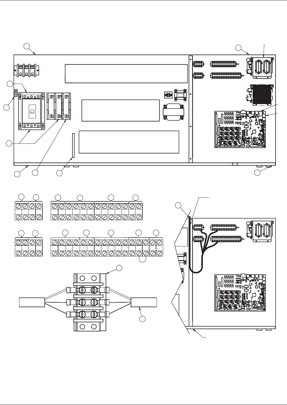
Water-Cooled, Glycol-Cooled and GLYCOOL Systems
103 Liebert® DS™
Figure 79 Electrical field connections—Upflow and downflow models, single molded case switch
disconnect with main fuses
75 76 94 95 96 97 91 11 12
92 93 80 81
73
37C 38C 37B 38B 37 38 24 70 71 230
50 51 55 56
88
83
82 89
84
59
58 85
Al t e r n ate
Location
72
17 18 916 19
20
10
8
21
23
24
22
7
3
1
13
6
15
2
4
AB
C
AB
CD
P64
P67
CONTACTORS
6
60Hz
3UPFLOW
5
12
SH49-1
49-3
11
E
E
OVERCURRENT PROTECTION DEVICES
CONTACTORS, RELAYS, &
OVERLOAD PROTECTORS
Liebert
IntelliSlot
Housing
Downflow
DOWNFLOW LOW-VOLT SECTION
CAUTION:
Risk of broken or shorted low volt
wiring. Field installed low volt wiring
must be routed with loop as shown
to allow electric box to swing.
Typical orientation of components shown. Component location
varies by option and unit size
Item 12 Installation Conditions
1. Follow all local installation codes.
2. Do not run CAN cables in same conduit, raceway, or
chase as high voltage wires (120-600V).
3. Separate high volt wires from CAN wires by 12 inches.
4. For runs greater than 350ft(107m), contact Liebert factory.
Point of Hinged Low-Volt
Electric Box
LIEBERT DS UPFLOW LOW-VOLT SECTION
50 & 60Hz
D
DPN000807
Pg. 2, Rev. 7
See 4.2 - Standard Electrical Connections, 4.3 -
Optional Electrical Connections and 4.4 - Optional
Low-Voltage Terminal Package Connections for keys
to numbered components.
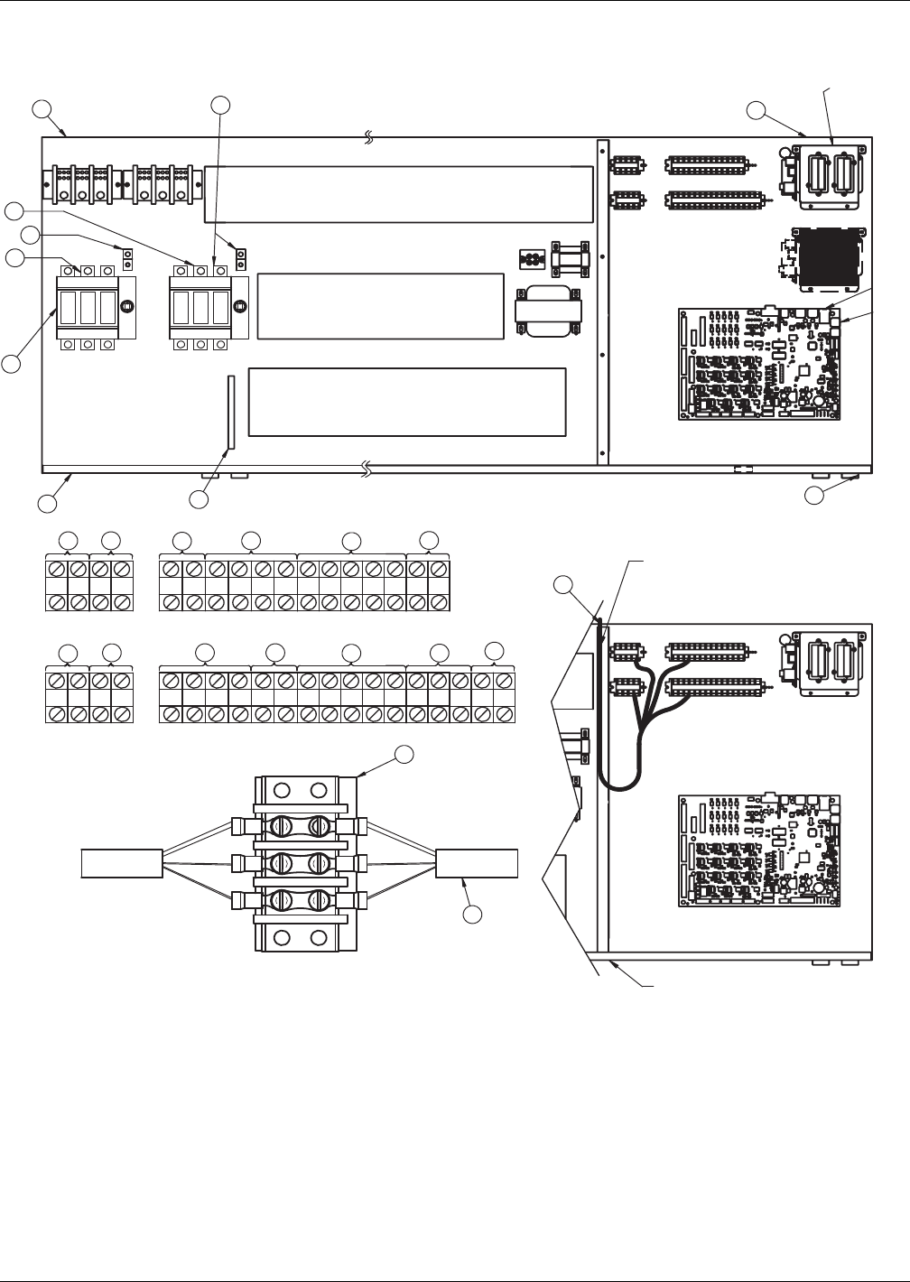
Water-Cooled, Glycol-Cooled and GLYCOOL Systems
Liebert® DS™104
Figure 80 Electrical field connections—Upflow and downflow models, dual fused disconnect switches
75 76 94 95 96 97 91 11 12
92 93 80 81
72
37C38C37B38B 37 38 24 70 71 230
50 51 55 56
88
83
82 89
84
59
58 85
PRIMARY SECONDARY
Alternate
Location
Alternate
Location
73
17 18 916 19
20
10
8
21
23
24
22
7
3
1
13
6
15
14
4
AB
CD
AB
CD
P64
P67
6
60 Hz
3
15
2
12
SH49-1
49-3
11
E
E
OVERCURRENT PROTECTION DEVICES
CONTACTORS, RELAYS and
OVERLOAD PROTECTORS
Typical orientation of components shown.
Component location varies by option and unit size
DOWNFLOW
UPFLOW
DOWNFLOW LOW-VOLTAGE SECTION
Liebert
IntelliSlot
Housing
Item 12 Installation Conditions
1. Follow all local installation codes.
2. Do not run CAN cables in same conduit, raceway or
chase as high-voltage wires (120-600V).
3. Separate high-voltage wires from CAN wires by 12" (305mm).
4. Contact Liebert factory for runs greater than 350ft. (107m).
5. All electrical loads may not be capable of being connected to both
power feeds, with automatic transfer switch.
Consult local representative for dual power configurations available.
Point of Hinged Low-Voltage
Electric Box
DS UPFLOW LOW-VOLTAGE SECTION
DPN000807
Pg. 3, Rev. 8
CAUTION:
Risk of broken or shorted low-voltage
wiring. Field-installed low-voltage wiring
must be routed with loop as shown
to allow electric box to swing.
CONTACTORS
See 4.2 - Standard Electrical Connections, 4.3 -
Optional Electrical Connections and 4.4 - Optional
Low-Voltage Terminal Package Connections for keys
to numbered components.

Water-Cooled, Glycol-Cooled and GLYCOOL Systems
105 Liebert® DS™
4.2 STANDARD ELECTRICAL CONNECTIONS
Source: DPN000807, Rev. 8
1. Primary high voltage entrance—2.5" (64mm); 1.75" (44mm); 1.375" (35mm) diameter
concentric knockouts located in bottom of box.
2. Secondary high voltage entrance—2.5" (64mm); 1.75" (44mm); 1.375" (35mm) diameter
concentric knockouts located in top of box.
3. Primary low voltage entrance—Quantity (3) 1.375" (35mm) diameter knockouts located in
bottom of unit.
4. Secondary low voltage entrance—Quantity (3) 1. 375" (35mm) diameter knockouts located in
top of box.
5. Three phase electrical service—Terminals are on main fuse block (disregard if unit has
optional disconnect switch). Three-phase service not by Emerson.
6. Earth ground—Terminal for field-supplied earth grounding wire. Earth grounding required for
Liebert units.
7. Remote unit shutdown—Replace existing jumper between Terminals 37 & 38 with field-
supplied normally closed switch having a minimum 75VA, 24VAC rating. Use field-supplied
Class 1 wiring.
8. Customer alarm inputs—Terminals for field-supplied, normally open contacts, having a
minimum 75VA, 24VAC rating, between Terminals 24 & 50, 51, 55 & 56. Use field-supplied
Class 1 wiring. Terminal availability varies by unit options.
9. Common alarm—On any alarm, normally open dry contact is closed across Terminals 75 & 76
for remote indication. 1A, 24VAC maximum load. Use Class 1 field-supplied wiring.
10. Heat rejection interlock—On any call for compressor operation, normally open dry contact is
closed across Terminals 70 & 71 (Circuit 1), 230 (Circuit 2) to heat rejection equipment. 1A,
24VAC maximum load. Use field-supplied Class 1 wiring. When a Liebert DS unit is paired with a
Liebert MC series condenser, remove jumper between Terminal 71 and Terminal 230. Three
wires must connect Terminals 70, 71 and 230 of the indoor unit to Terminals 70, 71 and 230 of the
Liebert MC series condenser.

Water-Cooled, Glycol-Cooled and GLYCOOL Systems
Liebert® DS™106
4.3 OPTIONAL ELECTRICAL CONNECTIONS
Source: DPN000807, Rev. 7
11. Unit factory installed disconnect switch, Fuse Block and Main Fuses—Two types of
disconnect switches are available: Non-Locking and Locking. The Non-Locking Type consists of a
non-automatic molded case switch operational from the outside of the unit. Access to the
high-voltage electric panel compartment can be obtained with the switch in either the On or Off
position. The Locking Type is identical except access to the high-voltage electric panel
compartment can be obtained only with the switch in the Off position. Units with fused
disconnects are provided with a defeater button that allows access to the electrical panel when
power is On. The molded case switch disconnect models contain separate main fuses. Units with
fused disconnect have main fuses within the disconnect. Only fused disconnects are used on dual
disconnect options.
12. Secondary disconnect switch and earth ground
13. Three-phase electrical service—Terminals are on top of disconnect switch. Three-phase
service not by Emerson.
14. Smoke sensor alarm—Factory-wired dry contacts from smoke sensor are 91-common, 92-NO,
and 93-NC. Supervised contacts, 80 & 81, open on sensor trouble indication. This smoke sensor is
not intended to function as or replace any room smoke detection system that may be required by
local or national codes. 1A, 24VAC maximum load. Use field-supplied Class 1 wiring.
15. Reheat and humidifier lockout—Remote 24VAC required at Terminals 82 & 83 for lockout of
reheat and humidifier.
16. Condensate alarm (with condensate pump option)—On pump high water indication,
normally open dry contact is closed across Terminals 88 & 89 for remote indication. 1A, 24VAC
maximum load. Use field-supplied Class 1 wiring.
17. Remote humidifier—On any call for humidification, normally open dry contact is closed across
Terminals 11 & 12 to signal field-supplied remote humidifier. 1A, 24VAC maximum load. Use
Class 1 field-supplied wiring.
18. Auxiliary cool contact—On any call for Econ-O-coil operation, normally open dry contact is
closed across Terminals 72 & 73 on dual cool units only. 1A, 24VAC maximum load. Use
field-supplied Class 1 wiring.
4.4 OPTIONAL LOW-VOLTAGE TERMINAL PACKAGE CONNECTIONS
Source: DPN000807, Rev. 7
19. Remote unit shutdown—Two additional contact pairs available for unit shutdown (labeled as
37B & 38B, 37C and 38C). Replace jumpers with field-supplied, normally closed switch having a
minimum rating of 75VA, 24VAC. Use field-supplied Class 1 wiring.
20. Common alarm—On any alarm, two additional normally open dry contacts are closed across
Terminals 94 & 95 and 96 & 97 for remote indication. 1A, 24VAC maximum load. Use
field-supplied Class 1 wiring.
21. Main fan auxiliary switch—On closure of main fan contactor, normally open dry contact is
closed across Terminals 84 & 85 for remote indication. 1A, 24VAC maximum load. Use
field-supplied Class 1 wiring.
22. Liebert Liqui-tect™ shutdown and dry contact—On Liebert Liqui-tect activation, normally
open dry contact is closed across Terminals 58 & 59 for remote indication (Liebert Liqui-tect
sensor ordered separately). 1A, 24VAC maximum load. Use field-supplied Class 1 wiring.
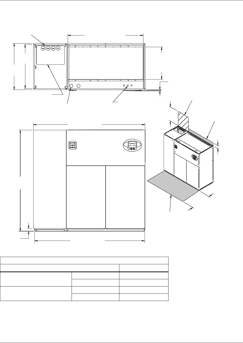
Water-Cooled, Glycol-Cooled and GLYCOOL Systems
107 Liebert® DS™
4.5 DIMENSIONS—LIEBERT DS 028-042, DOWNFLOW, WATER/GLYCOL/GLYCOOL MODELS
Figure 81 Dimensions—water/glycol/GLYCOOL, 28-42kW (8-12 ton), downflow, all compressors with
centrifugal fans
Table 80 Weights—Water/glycol/GLYCOOL, 28-42kW (8-12 ton), downflow, all compressors
Dry Weight, Approximate, lb. (kg)
Model Type Model Size: 028-042
Semi-Hermetic Compressor Water/Glycol 1930 (877)
GLYCOOL/Dual-Cool 2080 (945)
Scroll or Digital Scroll Compressor Water/Glycol 1780 (809)
GLYCOOL/Dual-Cool 1930 (877)
Source: DPN000894, Rev. 4
33"
(838mm)
Filters are accessible
through top of unit only.
Downflow electrical
connections can be made
from top or bottom of unit.
FRONT VIEW
TOP VIEW
Air Inlet Opening
Shaded area indicates a
recommended minimum
clearance for component
access.
86" (2184mm)
DPN000894
Rev. 4
2"
(51mm) 85" (2159mm)
76"
(1930mm)
35"
(889mm)
56-7/8"
(1445mm)
Opening
3/4"
(19mm)
Bezels
Secondary Entrance
High-Volt Connection(s)
Condenser Cleanout
Access
Secondary Entrance
Low-Volt Connections
24-3/8"
(619mm)
Opening
5"
(127mm)
24"
(610mm)
Required for
condenser cleanout
Minimum required
for filter replacement
34" (864mm)
Secondary Condenser
Fluid Piping Entrance
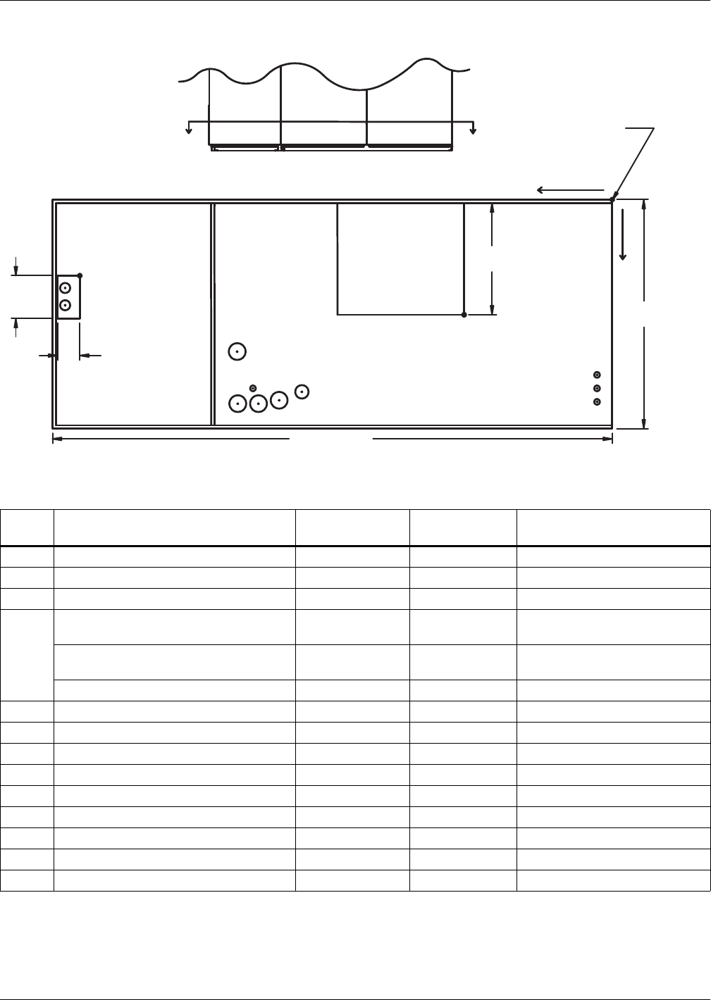
Water-Cooled, Glycol-Cooled and GLYCOOL Systems
Liebert® DS™108
Figure 82 Primary connection locations—Water/glycol/GLYCOOL, 28-42kW (8-12 ton), downflow, all
compressors with centrifugal fans
Table 81 Piping data—Water/glycol/GLYCOOL, 28-42kW (8-12 ton), downflow, all compressors
Point Description
X
in. (mm)
Y
in. (mm)
Connection Size / Opening
in. (mm)
W Water/Glycol/GLYCOOL Access 79-15/16 (2030) 9-1/16 (230) 3-1/2 x 8 (89 x 203)
WS Water/Glycol/GLYCOOL Supply 82-15/16 (2107) 10-15/16 (278) 1-5/8" Cu Sweat
WR Water/Glycol/GLYCOOL Return 82-15/16 (2107) 14-1/16 (357) 1-5/8" Cu Sweat
CD
Condensate Drain
(infrared humidifier or no humidifier) * 46 (1168) 29-1/2 (749) 3/4" FPT
Condensate Drain
(steam generating humidifier) * 46 (1168) 29-1/2 (749) 1-1/4" FPT
W/ Optional Pump 46 (1168) 29-1/2 (749) 1/2" Cu Sweat
HUM Humidifier Supply Line 53-1/2 (1359) 29 (737) 1/4" Cu Sweat
ECS Dual-Cool Supply 54-7/8 (1394) 22-9/16 (573) 1-5/8" Cu Sweat
ECR Dual-Cool Return 49-13/16 (1265) 28-1/2 (724) 1-5/8" Cu Sweat
E1 Electrical Conn. (High Volt) 55-1/2 (1410) 31-1/4 (794) 2-1/2"
E2 Electrical Conn. (High Volt) 52-7/16 (1332) 31-1/4 (794) 2-1/2"
LV1 Electrical Conn. (Low Volt) 2-1/4 (57) 27 (686) 7/8"
LV2 Electrical Conn. (Low Volt) 2-1/4 (57) 29 (737) 7/8"
LV3 Electrical Conn. (Low Volt) 2-1/4 (57) 31 (787) 7/8"
B Blower Outlet 21-15/16 (557) 18-1/16 (459) 18-3/4 x 16-1/16 (476 x 408)
* Field pitch condensate drain line a minimum of 1/8" (3.2 mm) per foot (305 mm). All units contain a factory-installed condensate trap. Do
not trap external to the unit. Drain line may contain boiling water. Select appropriate drain system materials. The drain line must comply
with all local codes.
Piping dimensions shown are connection sizes; field piping sizes may be different depending on distance. Refer to user manual, SL-18825.
Source: DPN000900, Rev. 3
WS
WR
W
ECS
ECR
E1 E2
HUM
CD
B
O
X
Y
FRONT VIEW
LV1
NOTE: Drawing not to scale.
Tolerance on
all piping dimensions
is ± 1/2" (13mm).
8"
(203mm)
3-1/2"
(89mm)
BLOWER
OUTLET
All dimensions from
rear corner of unit
including panels
16-1/16"
(408mm)
35"
(889mm)
86" (2184mm)
LV2
LV3
SECTION A-A
FRONT OF UNIT
AA
DPN000900
Rev. 3
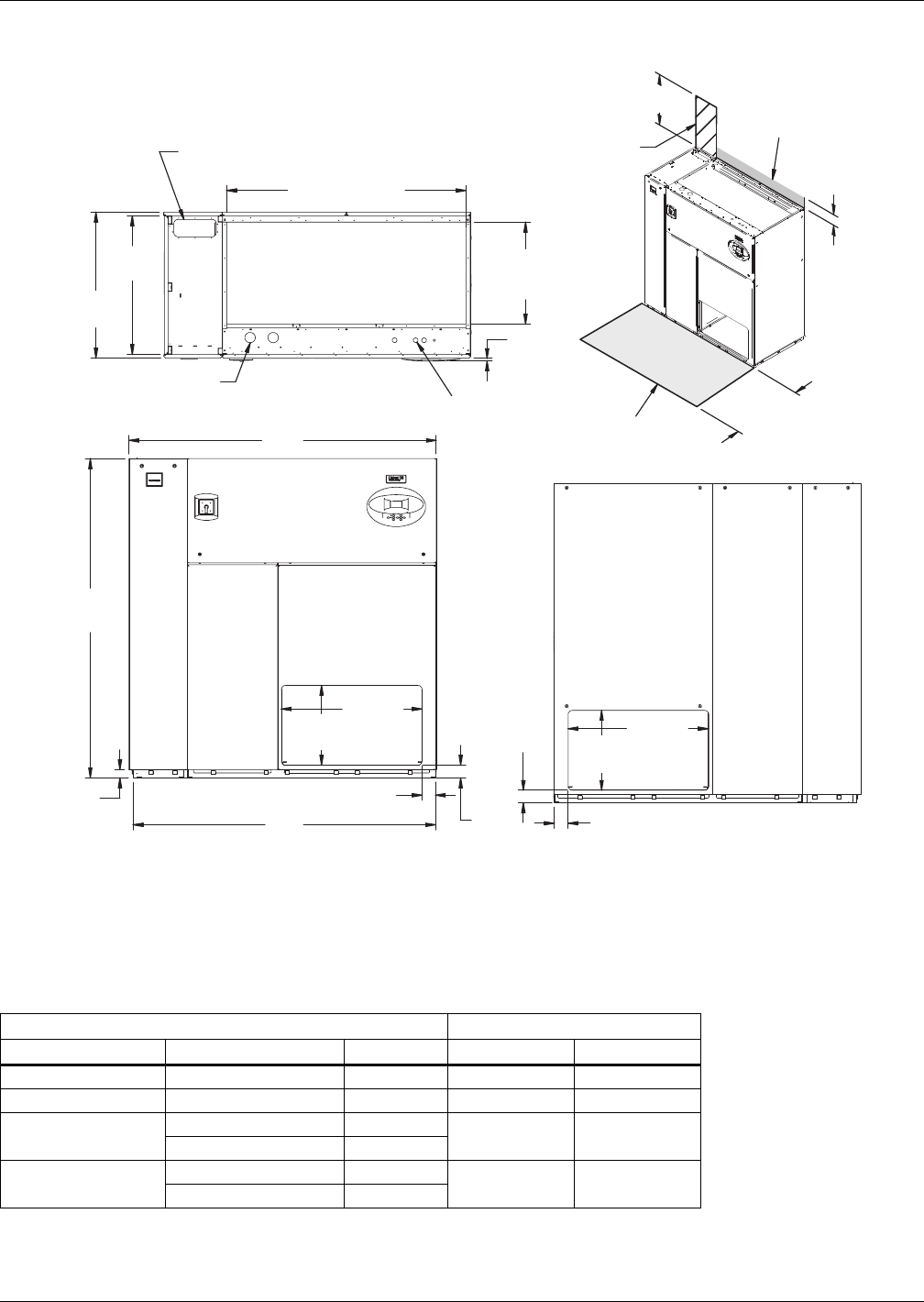
Water-Cooled, Glycol-Cooled and GLYCOOL Systems
109 Liebert® DS™
Figure 83 Dimensions—downflow, water/glycol/GLYCOOL systems, 28-42kW (8-12 ton), with EC fans,
front and/or rear discharge models
Dry Weight, lb (kg) Approximate Dimensions
Compressor Type Model 028-042 A B
Semi-Hermetic Dual Cool 1930 (877) 86" (2184mm) 85" (2159mm)
Scroll / Digital Dual Cool 1620 (736) 73" (1854mm) 72" (1829mm)
Semi-Hermetic Water/Glycol 1930 (877) 86" (2184mm) 85" (2159mm)
GLYCOOL/Dual Cool 2080 (945)
Scroll / Digital Water/Glycol 1780 (809) 86" (2184mm) 85" (2159mm)
GLYCOOL/Dual Cool 1930 (877)
Source: 310697, Pg. 1, Rev. 0
Customer Piping and Wiring Connections
1. For primary connection locations see standard submittals DPN000803, DPN000804 or DPN000900.
A floor stand at least 9" high is recommended if primary connections locations are to be used.
2. If no floor stand is used and unit is placed directly on the floor, then do the following:
a) Use secondary connection locations (shown on standard floor planning submittals).
b) Order a condensate pump.
c) Field pipe condensate and humidier line (if ordered) to secondary connection point in
compressor section.
d) Or order additional SFA's to relocate connection locations
AIR INLET OPENING
Secondary Entrance
High-Voltage Connection(s)
Shaded area indicates a
recommended minimum
clearance for component access.
Secondary Refrigerant
Piping Entrance
Secondary Entrance
Low-Voltage Connections
TOP VIEW
FRONT VIEW
REAR VIEW
310697
Pg. 1, Rev. 0
Air Outlet
Opening Air Outlet
Opening
2"
(51mm)
76"
(1930mm)
56-7/8"
(1445mm) Opening
24-3/8"
(619mm)
Opening
3/4"
(19mm)
Bezels
33"
(838mm)
35"
(889mm)
33-1/2"
(851mm) 33-3/8"
(848mm)
19"
(483mm)
3"
(77mm)
3"
(76mm)
3-1/4"
(81mm)
5"
(127mm)
19"
(483mm)
34"
(864mm)
3-1/4"
(83mm)
Required for Condenser
cleanout on Water/Glycol or
GLYCOOL/Dual Cool
24" (610mm)
Minimum required
for filter replacement
A
B
Filters are accessible
only through top of unit.
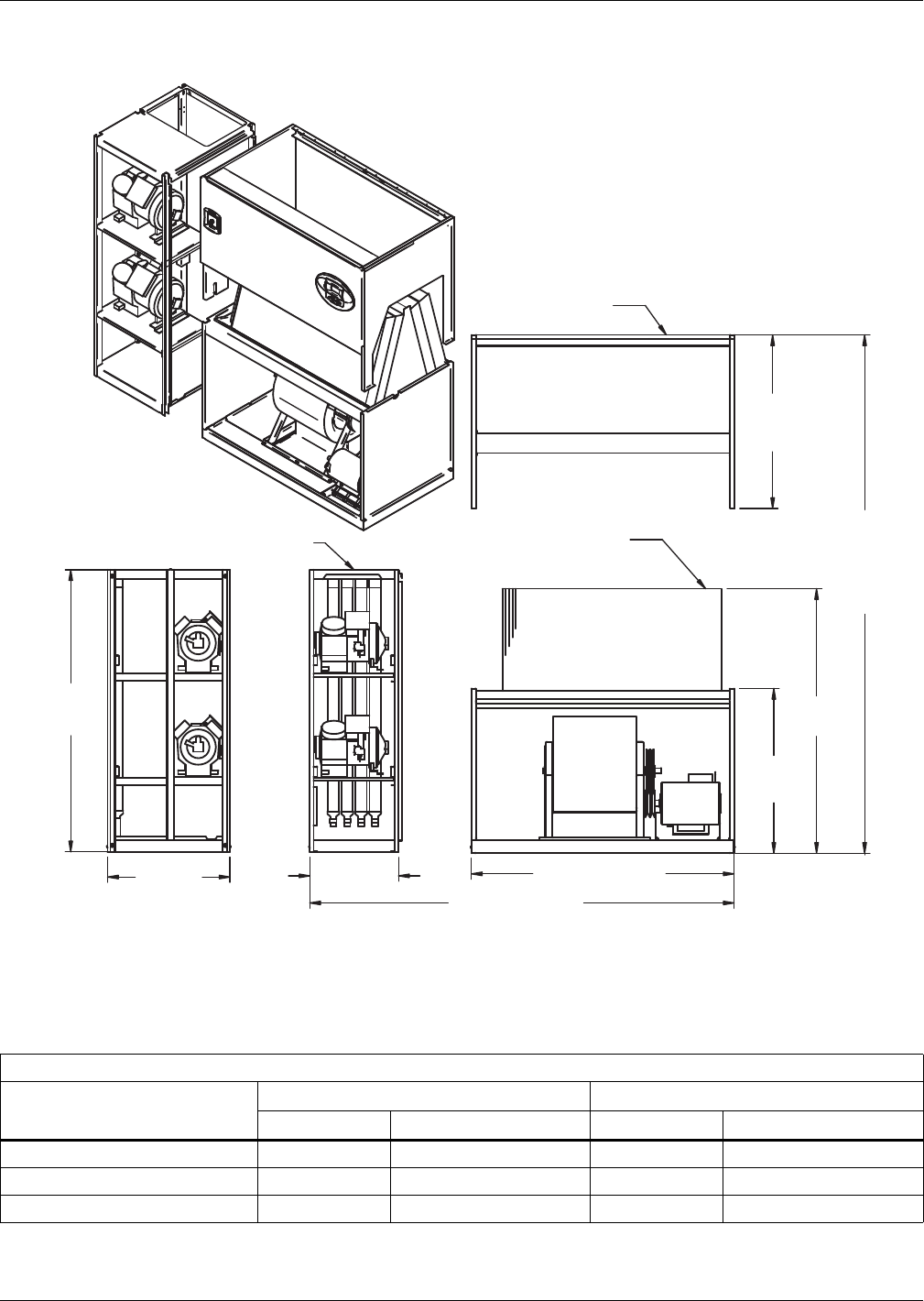
Water-Cooled, Glycol-Cooled and GLYCOOL Systems
Liebert® DS™110
Figure 84 Disassembly dimensions—Water/glycol/GLYCOOL, 28-42kW (8-12 ton), downflow, all
compressors with centrifugal fans
Table 82 Component weights—Water/glycol/GLYCOOL, 28-42kW (8-12 ton), downflow, all compressors
Dry Weight, Approximate, Including Panels, lb (kg)
Component
Semi-Hermetic Compressor Scroll or Digital Scroll Compressor
Water/Glycol GLYCOOL/Dual-Cool Water/Glycol GLYCOOL/Dual-Cool
Compressor Assembly 950 (432) 950 (432) 800 (364) 800 (364)
Filter and Electric Box Assembly 210 (96) 210 (96) 210 (96) 210 (96)
Blower and Coil Assembly 770 (350) 920 (418) 770 (350) 920 (418)
Source: DPN000899, Rev. 2
59" (1499mm)
DPN000899
Rev. 2
33"
(838mm)
26"
(660mm)
76"
(1930mm)
85" (2159mm)
Assembled Length
76"
(1930mm)
Assembled
Height
60-3/16"
(1529mm)
37"
(940mm)
39"
(991mm)
Compressor Assembly
Filter & Electric
Box Assembly
Blower & Coil
Assembly
NOTES: Drawing views are simplified with panels removed to show overall dimensions.
See disassembly and handling instructions in installation manual.
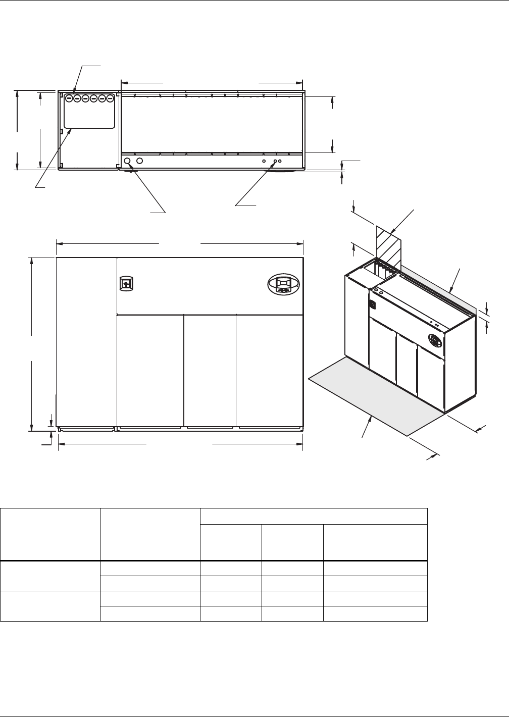
Water-Cooled, Glycol-Cooled and GLYCOOL Systems
111 Liebert® DS™
4.6 DIMENSIONS—LIEBERT DS 053-077, DOWNFLOW, WATER/GLYCOL/GLYCOOL MODELS
Figure 85 Dimensions—Water/glycol/GLYCOOL, 53-77kW (15-22 ton), downflow, all compressors with
centrifugal fans
Table 83 Weights—Water/glycol/GLYCOOL, 53-77kW (15-22 ton), downflow, all compressors
Compressor Type Cooling Type
Model Size
053
lb (kg)
070
lb (kg)
077 *
Standard Scroll Only
lb (kg)
Semi-Hermetic
Compressor
Water/Glycol 2650 (1205) 2700 (1228) 2750 (1250)
GLYCOOL/Dual-Cool 2830 (1287) 2880 (1310) 2930 (1332)
Scroll or Digital Scroll
Compressor
Water/Glycol 2220 (1010) 2270 (1032) 2320 (1055)
GLYCOOL/Dual-Cool 2400 (1091) 2450 (1114) 2500 (1137)
* Digital scroll compressors not available on DS 077
Source: DPN00931, Rev. 4
Notes: Filters are accessible
through top of unit only.
Downflow electrical
connections can be made
from top or bottom of unit.
Shaded area indicates a
recommended minimum
clearance for component
access.
Required for
condenser cleanout
5"
(127mm)
34"
(864mm)
DPN000931
Rev. 4
76"
(1930mm)
TOP VIEW
Air Inlet Opening
Secondary Entrance
High-Volt Connection(s)
Secondary Entrance
Low-Volt Connections
80" (2032mm) Opening
35"
(889mm
24-5/8"
(625mm)
Opening
3/4" (20mm)
Bezels
Secondary Condenser
Fluid Piping Entrance
Condenser Cleanout Access
33"
(838mm)
24"
(610mm)
FRONT VIEW
2"
(51mm)
108" (2743mm)
109"
(2769mm)
Minimum
required
for filter
replacement
Digital scroll compressors
not available on 077 models
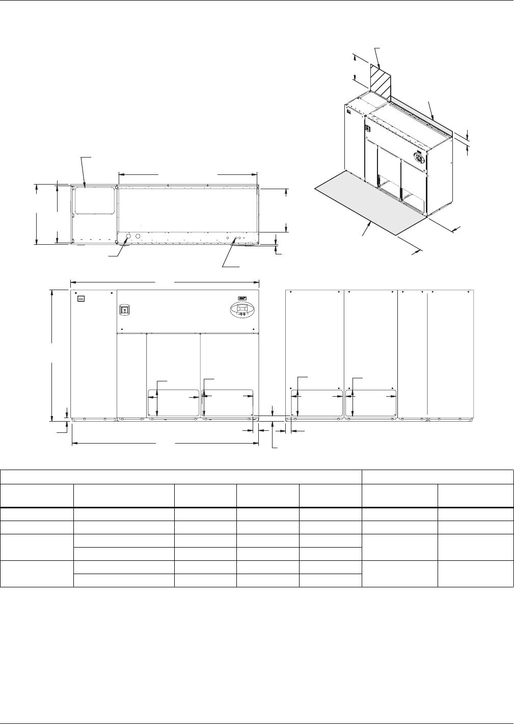
Water-Cooled, Glycol-Cooled and GLYCOOL Systems
Liebert® DS™112
Figure 86 Dimensions—downflow, water/glycol, GLYCOOL systems, 53-77kW (15-22 ton), front and/or
rear discharge models
Dry Weight, lb (kg) Approximate Dimensions, in. (mm)
Compressor
Type Model 53 70 77 A B
Semi-Hermetic Dual Cool 2530 (1150) 2580 (1173) 2630 (1196) 109 (2769) 108 (2743)
Scroll / Digital Dual Cool 2100 (955) 2150 (978) 2200 (1000) 98 (2489) 97 (2464)
Semi-Hermetic Water/Glycol 2650 (1205) 2700 (1228) 2750 (1250) 109 (2769) 108 (2743)
GLYCOOL/Dual Cool 2830 (1287) 2880 (1310) 2930 (1332)
Scroll / Digital Water/Glycol 2220 (1010) 2270 (1032) 2320 (1055) 109 (2769) 85 (2159)
GLYCOOL/Dual Cool 2400 (1091) 2450 (1114) 2500 (1137)
Source: 310697, Pg. 2, Rev. 0
Customer Piping and Wiring Connections
1. For primary connection locations see standard submittals DPN000928,
DPN000929 or DPN000933.
A floor stand at least 9" high is recommended if primary connections locations are to be used.
2. If no floor stand is used and unit is placed directly on the floor, then do the following:
a) Use secondary connection locations (shown on standard floor planning submittals).
b) Order a condensate pump.
c) Field pipe condensate and humidier line (if ordered) to secondary connection point in
compressor section.
d) Or order additional SFA's to relocate connection locations
AIR INLET OPENING
Secondary Entrance
High-Voltage Connection(s)
Shaded area indicates a
recommended minimum
clearance for component access.
Secondary Refrigerant
Piping Entrance
Secondary Entrance
Low-Voltage Connections
TOP VIEW
FRONT VIEW REAR VIEW
310697
Pg. 2, Rev. 0
Air Outlet
Opening
Air Outlet
Opening
2"
(51mm)
29-1/4"
(743mm)
Air Outlet
Opening
29-1/4"
(743mm)
29-5/8"
(752mm) Air Outlet
Opening
29-5/8"
(752mm)
15-1/8"
(384mm)
15-1/8"
(384mm)
15-1/8"
(384mm)
15-1/8"
(384mm)
76"
(1930mm)
25-5/8"
(619mm)
Opening
80" (2032mm)
Opening
3/4"
(19mm)
33"
(838mm)
35"
(889mm)
3-1/8"
(79mm)
5"
(127mm)
34"
(864mm)
3-1/4"
(83mm)
3-1/4"
(83mm)
Required for Condenser
cleanout on Water/Glycol or
GLYCOOL/Dual Cool
24" (610mm) Minimum required
for filter replacement
A
B
Filters are accessible
only through top of unit.
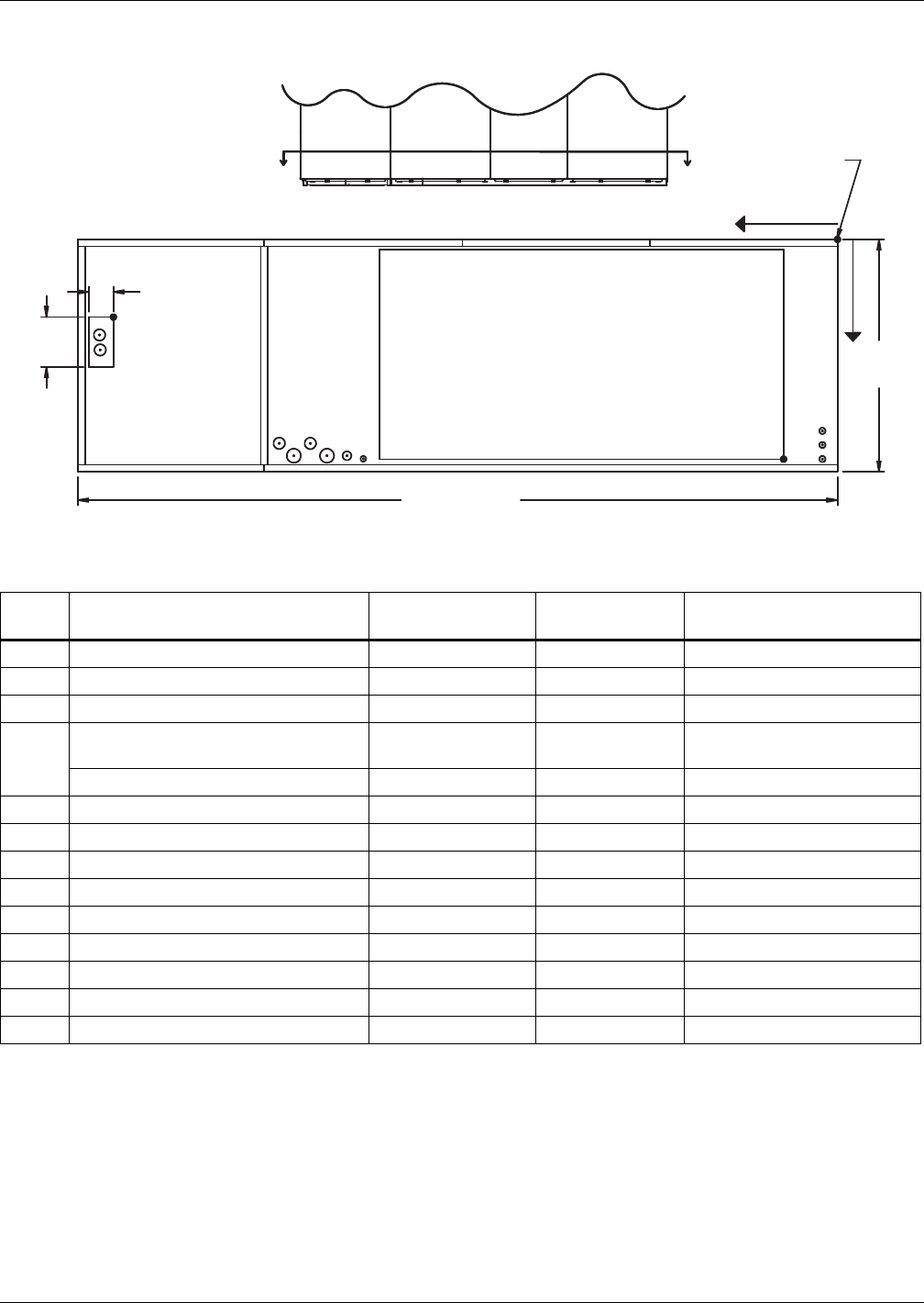
Water-Cooled, Glycol-Cooled and GLYCOOL Systems
113 Liebert® DS™
Figure 87 Primary connection locations—Water/glycol/GLYCOOL, 53-77kW (15-22 ton), all compressor
models with EC fans
Table 84 Piping data—Water/glycol/GLYCOOL, 53-77kW (15-22 ton), downflow with EC fans
Point Description
X
in. (mm)
Y
in. (mm)
Connection Size / Opening
in. (mm)
W Water/Glycol/GLYCOOL Access 103 (2616) 9 (229) 3-1/2 x 8 (89x203)
WS Water/Glycol/GLYCOOL Supply 104-3/4 (2661) 11 (279) 2-1/8 Cu Sweat
WR Water/Glycol/GLYCOOL Return 104-3/4 (2661) 15 (381) 2-1/8 Cu Sweat
CD
Condensate Drain
(Infrared Humidifier or No Humidifier)* 68-3/8 (1737) 31-3/8 (797) 3/4 FPT
W/ Optional Pump 68-3/8 (1737) 31-3/8 (797) 1/2 Cu Sweat
HUM Humidifier Supply Line 76-1/2 (1943) 29 (736) 1/4 Cu Sweat
ECS** Dual-Cool Supply 78-5/8 (1997) 22-1/4 (565) 2-1/8 Cu Sweat
ECR** Dual-Cool Return 73-15/16 (1862) 26-9/16 (675) 2-1/8 Cu Sweat
E1 Electrical Conn. (High Volt) 78-1/2 (1994) 31-1/8 (790) 2-1/2
E2 Electrical Conn. (High Volt) 75-3/8 (1915) 31-1/8 (790) 2-1/2
LV1 Electrical Conn. (Low Volt) 2 (51) 29 (737) 7/8
LV2 Electrical Conn. (Low Volt) 2 (51) 30-7/8 (784) 7/8
LV3 Electrical Conn. (Low Volt) 2 (51) 32 (813) 7/8
B1 Blower Outlet 4-1/2 (114) 33 (838) 58-3/8x30 (1483x762)
* Field pitch condensate drain line a minimum of 1/8" (3.2 mm) per foot (305mm). All units contain a factory-installed condensate trap. Do
not trap external to the unit. Drain line may contain boiling water. Select appropriate drain system materials. The drain line must comply
with all local codes.
** Supplied on Dual-Cooling systems only (four-pipe system)
Piping dimensions shown are connection sizes; field piping sizes may be different depending on distance. Refer to user manual, SL-18825.
Source: DPN002183, Rev. 0
FRONT OF UNIT DPN002183
Rev. 0
FRONT VIEW
SECTION A-A
NOTE: Drawing not to scale.
Tolerance on
all piping dimensions
is ± 1/2" (13mm).
ECS ECR
E1 E2
CD
LV1
LV2
LV3
X
Y
O
All dimensions from
rear corner of unit
including panels
35"
(889mm)
HUM
W
A
WS
WR
B1
8"
(203mm)
3-1/2"
(89mm)
109" (2769mm)
A
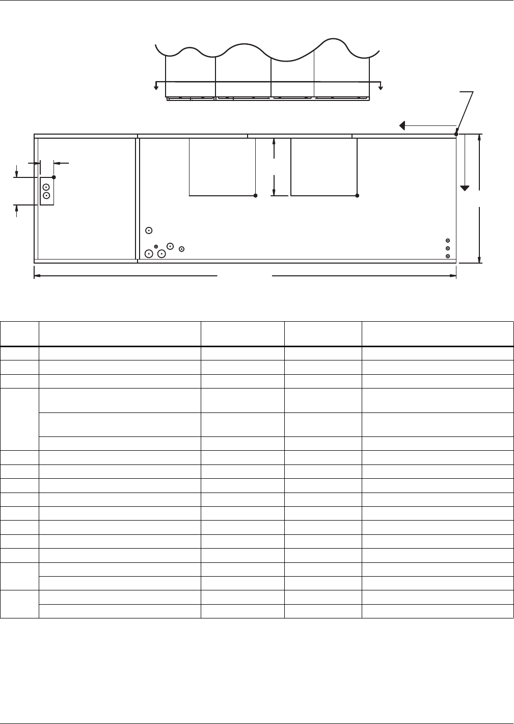
Water-Cooled, Glycol-Cooled and GLYCOOL Systems
Liebert® DS™114
Figure 88 Primary connection locations—Water/glycol/GLYCOOL, 53-77kW (15-22 ton), downflow, all
compressor models with centrifugal fans
Table 85 Piping data—Water/glycol/GLYCOOL, 53-77kW (15-22 ton), downflow
Point Description
X
in. (mm)
Y
in. (mm)
Connection Size / Opening
in. (mm)
W Water/Glycol/GLYCOOL Access 103 (2616) 9 (229) 3-1/2 x 8 (89 x 203)
WS Water/Glycol/GLYCOOL Supply 104-3/4 (2661) 11 (279) 2-1/8" Cu Sweat
WR Water/Glycol/GLYCOOL Return 104-3/4 (2661) 15 (381) 2-1/8" Cu Sweat
CD
Condensate Drain
(infrared humidifier or no humidifier)* 67-11/16 (1719) 30-1/2 (775) 3/4" FPT
Condensate Drain
(steam generating humidifier)* 67-11/16 (1719) 30-1/2 (775) 1-1/4" FPT
W/ Optional Pump 67-11/16 (1719) 30-1/2 (775) 1/2" Cu Sweat
HUM Humidifier Supply Line 76-1/2 (1943) 29 (736) 1/4" Cu Sweat
ECS** Dual-Cool Supply 78-5/8 (1997) 22-1/4 (565) 2-1/8" Cu Sweat
ECR** Dual-Cool Return 72 (1829) 29 (737) 2-1/8" Cu Sweat
E1 Electrical Conn. (High Volt) 78-1/2 (1994) 31-1/8 (790) 2-1/2"
E2 Electrical Conn. (High Volt) 75-3/8 (1915) 31-1/8 (790) 2-1/2"
LV1 Electrical Conn. (Low Volt) 1-7/8 (48) 28-1/2 (724) 7/8"
LV2 Electrical Conn. (Low Volt) 1-7/8 (48) 30-1/4 (768) 7/8"
LV3 Electrical Conn. (Low Volt) 1-7/8 (48) 32 (813) 7/8"
B1 Blower Outlet (15 x 15) 23-1/8 (587) 18-1/16 (459) 18-3/4 x 16-1/16 (476 x 408)
Blower Outlet (15 x 11) 27-3/4 (705) 18-1/16 (459) 14-3/4 x 16-1/16 (375 x 408)
B2 Blower Outlet (15 x 15) 50-3/8 (1280) 18-1/16 (459) 18-3/4 x 16-1/16 (476 x 408)
Blower Outlet (15 x 11) 54-3/8 (1381) 18-1/16 (459) 14-3/4 x 16-1/16 (375 x 408)
* Field pitch condensate drain line a minimum of 1/8" (3.2 mm) per foot (305 mm). All units contain a factory-installed condensate trap.
Do not trap external to the unit. Drain line may contain boiling water. Select appropriate drain system materials.
The drain line must comply with all local codes.
** Supplied on Dual-Cooling systems only (four-pipe system)
Piping dimensions shown are connection sizes; field piping sizes may be different depending on distance. Refer to user manual, SL-18825.
Source: DPN00933, Rev. 4
AA
W
ECS
ECR
E1 E2
HUM CD
B1
O
X
Y
B2
WS
WR
FRONT VIEW
LV1
NOTE: Drawing not to scale.
Tolerance on
all piping dimensions
is ± 1/2" (13mm).
8"
(203mm)
BLOWER
OUTLET
All dimensions from
rear corner of unit
including panels
16-1/16"
(408mm)
35"
(889mm)
LV2
LV3
SECTION A-A
FRONT OF UNIT
109" (2769mm)
3-1/2"
(89mm) BLOWER
OUTLET
DPN000933
Rev. 4
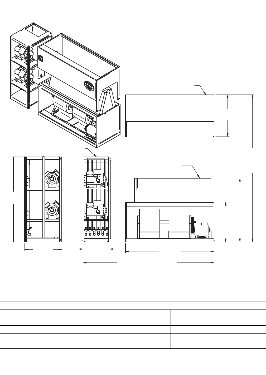
Water-Cooled, Glycol-Cooled and GLYCOOL Systems
115 Liebert® DS™
Figure 89 Disassembly dimensions—Water/glycol/GLYCOOL, 53-77kW (15-22 ton), downflow, all
compressors with centrifugal or EC fans
Table 86 Component weights—Water/glycol/GLYCOOL, 53-77kW (15-22 ton), downflow, all
compressors * with centrifugal or EC fans
Dry Weight, Approximate, Including Panels, lb (kg)
Component
Semi-Hermetic Compressor Scroll or Digital Scroll Compressor
Water/Glycol GLYCOOL/Dual-Cool Water/Glycol GLYCOOL/Dual-Cool
Compressor Assembly 1270 (578) 1270 (578) 840 (382) 840 (382)
Filter and Electric Box Assembly 250 (114) 250 (114) 250 (114) 250 (114)
Blower and Coil Assembly 1230 (560) 1410 (641) 1230 (560) 1410 (641)
* Digital scroll compressors not available on DS 077
Source: DPN000932, Rev. 3
Filter & Electric Box Assembly
Compressor Assembly
Blower & Coil
Assembly
39"
(991mm)
76"
(1930mm)
Assembled
Height
37"
(940mm)
Assembled Length
33"
(838mm)
76"
(1930mm)
NOTES: Drawing views are simplified with panels removed to show overall dimensions.
See disassembly and handling instructions in installation manual.
59-7/16"
(1509mm)
82"
(2083mm)
108"
(2743mm)
26"
(660mm)
DPN000932
Rev. 3
Digital scroll compressors
not available on 077 models
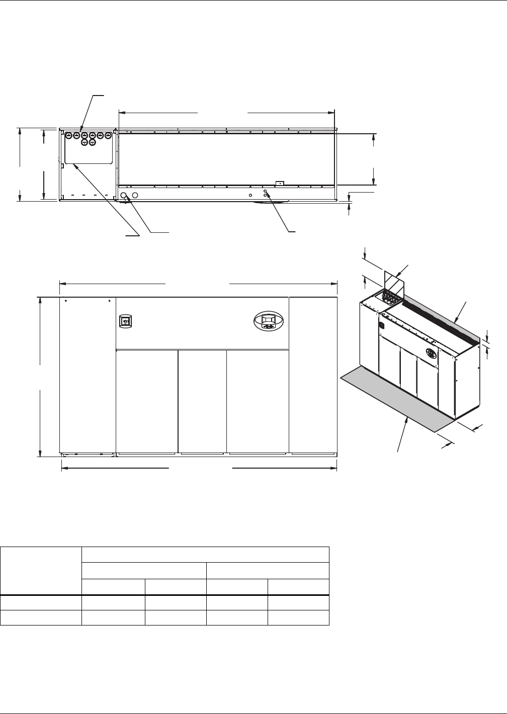
Water-Cooled, Glycol-Cooled and GLYCOOL Systems
Liebert® DS™116
4.7 DIMENSIONS—LIEBERT DS 105, DOWNFLOW, WATER/GLYCOL/GLYCOOL-COOLED
MODELS
Figure 90 Dimensions—Water/glycol/GLYCOOL 105kW (30 ton), downflow, semi-hermetic or scroll
compressors with centrifugal or EC fans
Table 87 Weights—Water/glycol/GLYCOOL 105kW (30 ton), downflow, semi-hermetic and scroll
compressors *
Compressor
Type
Dry Weight, Approximate, lb (kg)
Forward-Curved Fans EC Fans
Air-Cooled Dual-Cool Air-Cooled Dual-Cool
Semi-Hermetic 3410 (1550) 3770 (1714) 3144 (1426) 3504 (1589)
Scroll 3290 (1495) 3650 (1659) 3024 (1372) 3384 (1535)
* Digital scroll compressors not available on DS 105
Source: DPN001013, Rev. 4
TOP VIEW
Notes: Filters are accessible
through top of unit only.
Downflow electrical
connections can be made
from top or bottom of unit.
AIR INLET OPENING
Shaded area indicates a
recommended minimum
clearance be provided for
component access.
Secondary Entrance
High-Volt Connection(s)
FRONT VIEW DPN001013
Rev. 4
Secondary Entrance
Low-Volt Connections
Condenser Cleanout Access
Secondary Condenser
Fluid Entrance
Minimum required
for filter replacement
Required for
condenser
cleanout
24-3/8"
(619mm Opening
3/4"
(19mm Bezels
76"
(1930mm)
5"
(127mm)
34" (864mm)
24"
(610mm)
102-13/16"
(2611mm) Opening
33"
(838mm)
35"
(889mm)
132" (3353mm)
131" (3327mm)
Digital scroll
compressors not
available on 105
models
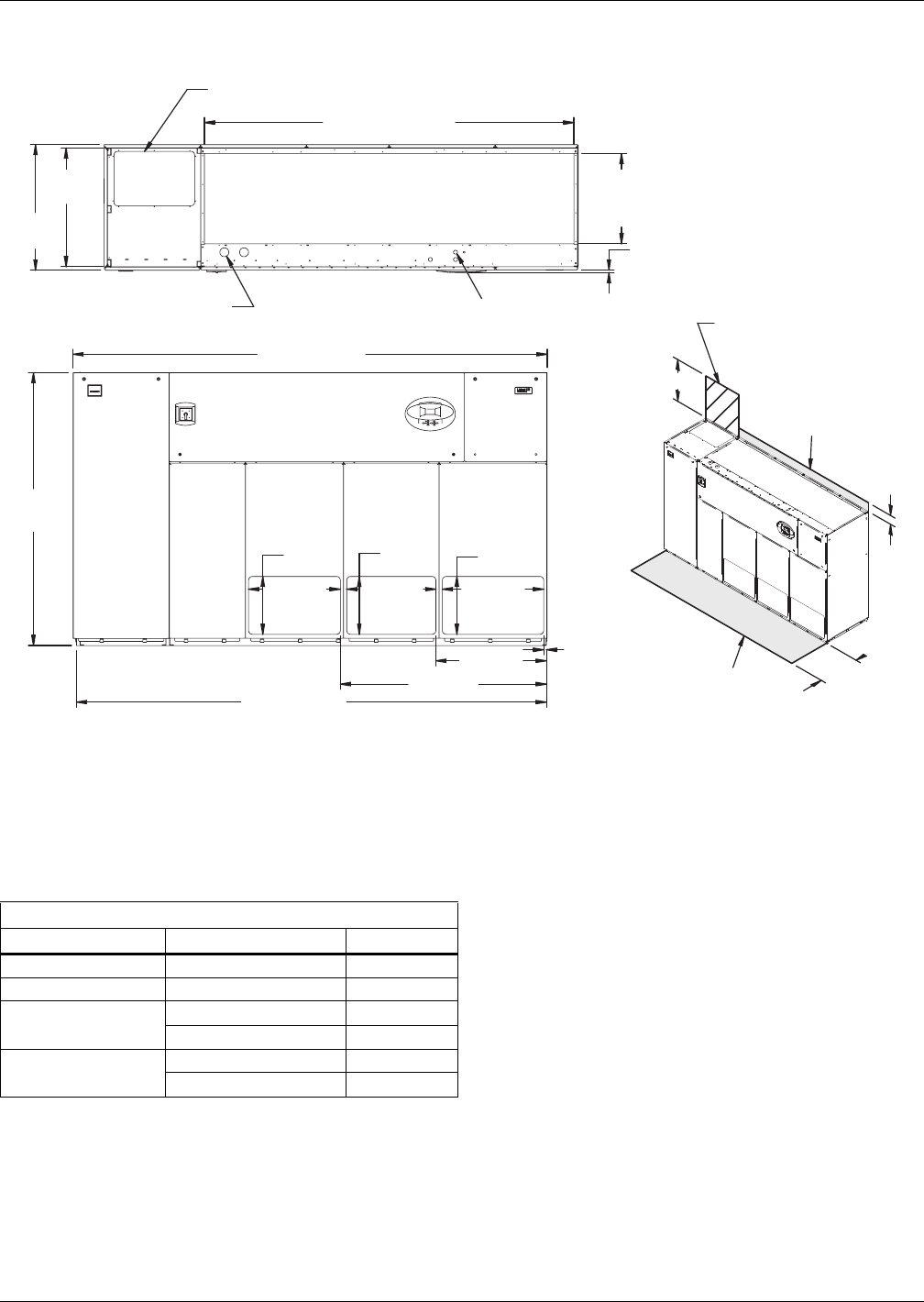
Water-Cooled, Glycol-Cooled and GLYCOOL Systems
117 Liebert® DS™
Figure 91 Dimensions—downflow, water/glycol,GLYCOOL systems, 105kW (30 ton), front discharge
models with EC fans
Dry Weight, lb (kg) Approximate
Compressor Type Model 105
Semi-Hermetic Dual Cool 3134 (1422)
Scroll / Digital Dual Cool 3014 (1367)
Semi-Hermetic Water/Glycol 3144 (1426)
GLYCOOL/Dual Cool 3504 (1589)
Scroll / Digital Water/Glycol 3024 (1372)
GLYCOOL/Dual Cool 3384 (1535)
Source: 310697, Pg. 3, Rev. 0
Customer Piping and Wiring Connections
1. For primary connection locations see standard submittals DPN001014 or DPN001015.
A floor stand at least 9" high is recommended if primary connections locations are to be used.
2. If no floor stand is used and unit is placed directly on the floor, then do the following:
a) Use secondary connection locations (shown on standard floor planning submittals).
b) Order a condensate pump.
c) Field pipe condensate and humidier line (if ordered) to secondary connection point in
compressor section.
d) Or order additional SFA's to relocate connection locations
Secondary Entrance
High-Voltage Connection(s)
Shaded area indicates a
recommended minimum
clearance for component access.
Secondary Refrigerant
Piping Entrance
Secondary Entrance
Low-Voltage Connections
TOP VIEW
FRONT VIEW
310697
Pg. 3, Rev. 0
Air Outlet
Opening
Air Outlet
Opening
Air Outlet
Opening
3/4"
(19mm)
25-5/8"
(649mm)
24-7/8"
(649mm)
28-1/4"
(718mm)
16-1/8"
(410mm)
16-1/8"
(410mm)
16-1/8"
(410mm)
24-3/8"
(619mm)
Opening
102-7/8" (2611mm)
Opening
132" (3353mm)
30-7/8"
(783mm)
57-1/2"
(1459mm)
131" (3326mm)
3/4"
(19mm)
33"
(838mm)
35"
(889mm)
5"
(127mm)
34"
(864mm)
Required for Condenser
cleanout on Water/Glycol or
GLYCOOL/Dual Cool
Downflow electrical
connections can be made
from top or bottom of unit
24" (610mm) Minimum required
for filter replacement
Filters are accessible
only through top of unit.
AIR INLET OPENING
76"
(1930mm)
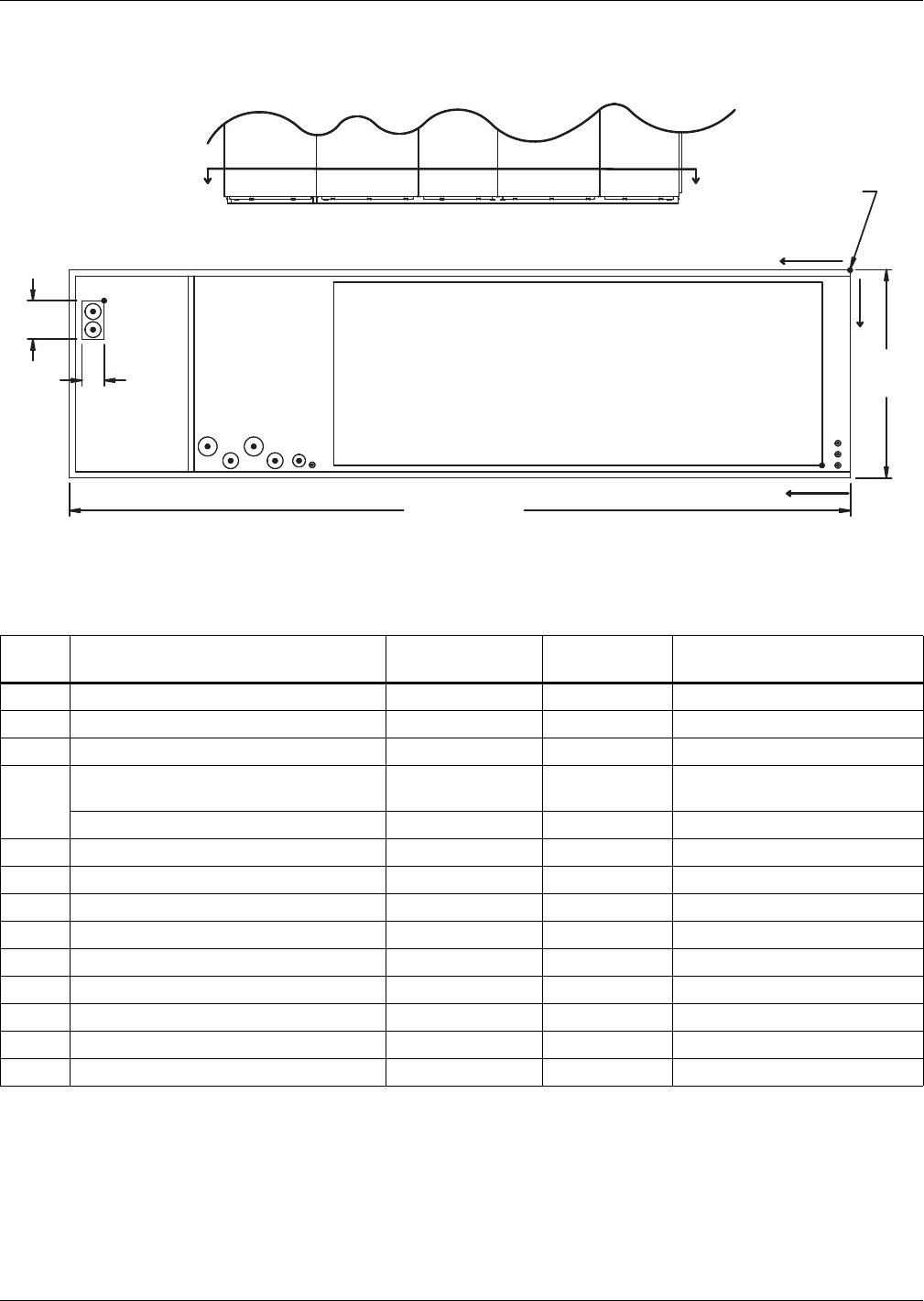
Water-Cooled, Glycol-Cooled and GLYCOOL Systems
Liebert® DS™118
Figure 92 Primary connection locations—Water/glycol/GLYCOOL 105kW (30 ton), downflow,
semi-hermetic or standard scroll compressors with EC fans
Table 88 Piping data—Water/glycol/GLYCOOL 105kW (30 ton), downflow with EC fans, semi-hermetic
and standard scroll compressors ***
Point Description
X
in. (mm)
Y
in. (mm)
Connection Size / Opening
in. (mm)
W Water/Glycol/GLYCOOL Access 125-15/16 (3199) 9 (229) 3-1/2 x 8 (89x203)
WS Water/Glycol/GLYCOOL Supply 127-7/8 (3248) 10-1/16 (256) 2-1/8 Cu Sweat
WR Water/Glycol/GLYCOOL Return 127-7/8 (3248) 13-1/4 (337) 2-1/8 Cu Sweat
CD
Condensate Drain
(Infrared Humidifier or No Humidifier)* 87-3/8 (2220) 31 (787) 3/4 FPT
W/ Optional Pump 83-13/16 (2129) 30 (762) 1/2 Cu Sweat
HUM Humidifier Supply Line 85-5/16 (2167) 32-1/2 (825) 1/4 Cu Sweat
ECS Dual-Cool Supply 101-7/8 (2588) 29 (737) 2-5/8 Cu Sweat
ECR Dual-Cool Return 94-9/16 (2402) 29 (737) 2-5/8 Cu Sweat
E1 Electrical Conn. (High Volt) 98-1/8 (2492) 31 (788) 2-1/2
E2 Electrical Conn. (High Volt) 91 (2311) 31 (788) 2-1/2
LV1 Electrical Conn. (Low Volt) 2 (51) 29 (737) 7/8
LV2 Electrical Conn. (Low Volt) 2 (51) 30-7/8 (784) 7/8
LV3 Electrical Conn. (Low Volt) 2 (51) 32 (813) 7/8
B1 Blower Outlet 4-1/2 (114) 33 (838) 77-3/8 x 30 (1965x762)
* Field pitch condensate drain line a minimum of 1/8" (3.2 mm) per foot (305 mm). All units contain a factory-installed condensate trap. Do
not trap external to the unit. Drain line may contain boiling water. Select appropriate drain system materials. The drain line must comply
with all local codes.
** Supplied on Dual-Cooling systems only (four-pipe system)
*** Digital scroll compressors not available on DS 105
Piping dimensions shown are connection sizes; field piping sizes may be different depending on distance. Refer to user manual, SL-18825.
Source: DPN002153, Rev. 0
8"
(203mm)
NOTES
Drawing not to scale.
Tolerance on
all piping dimensions
is ± 1/2" (13mm). SECTION A-A
FRONT VIEW
AA
FRONT OF UNIT DPN002153
Rev. 0
BLOWER
OUTLET
All dimensions from
Rear corner of unit
Including panels
ECS ECR
E1 E2
CD B1
LV1
LV2
LV3
O
Y
X
35"
(889mm)
132" (3353mm)
W
WS
WR
HUM
3-1/2"
(89mm)
Digital scroll compressors
not available on 105 models
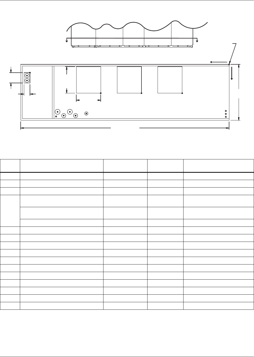
Water-Cooled, Glycol-Cooled and GLYCOOL Systems
119 Liebert® DS™
Figure 93 Primary connection locations—Water/glycol/GLYCOOL 105kW (30 ton), downflow,
semi-hermetic or standard scroll compressors with centrifugal fans
Table 89 Piping data—Water/glycol/GLYCOOL 105kW (30 ton), downflow, semi-hermetic and standard
scroll compressors ***
Point Description
X
in. (mm)
Y
in. (mm)
Connection Size / Opening
in. (mm)
W Water/Glycol/GLYCOOL Access 125-15/16 (3199) 9 (229) 3-1/2 x 8 (89 x 203)
WS Water/Glycol/GLYCOOL Supply 127-7/8 (3248) 10-1/16 (256) 2-1/8" Cu Sweat
WR Water/Glycol/GLYCOOL Return 127-7/8 (3248) 13-1/4 (337) 2-1/8" Cu Sweat
CD
Condensate Drain
(infrared humidifier or no humidifier)* 83-13/16 (2129) 30 (762) 3/4" FPT
Condensate Drain
(steam generating humidifier)* 83-13/16 (2129) 30 (762) 1-1/4" FPT
W/ Optional Pump 83-13/16 (2129) 30 (762) 1/2" Cu Sweat
HUM Humidifier Supply Line 102-3/4 (2610) 31-3/4 (806) 1/4" Cu Sweat
ECS** Dual-Cool Supply 101-7/8 (2588) 29 (737) 2-5/8" Cu Sweat
ECR** Dual-Cool Return 94-9/16 (2402) 29 (737) 2-5/8" Cu Sweat
E1 Electrical Conn. (High Volt) 98-1/4 (2496) 30 (762) 2-1/2"
E2 Electrical Conn. (High Volt) 88-7/16 (2246) 30 (762) 2-1/2"
LV1 Electrical Conn. (Low Volt) 2 (51) 27-1/2 (796) 7/8"
LV2 Electrical Conn. (Low Volt) 2 (51) 30-1/4 (768) 7/8"
LV3 Electrical Conn. (Low Volt) 2 (51) 32 (813) 7/8"
B1 Blower Outlet 28-1/4 (718) 18 (457) 14-1/2 x 15-7/8 (368 x 403)
B2 Blower Outlet 52 (1321) 18 (457) 14-1/2 x 15-7/8 (368 x 403)
B3 Blower Outlet 75-11/16 (1922) 18 (457) 14-1/2 x 15-7/8 (368 x 403)
* Field pitch condensate drain line a minimum of 1/8" (3.2 mm) per foot (305 mm). All units contain a factory-installed condensate trap. Do
not trap external to the unit. Drain line may contain boiling water. Select appropriate drain system materials. The drain line must comply
with all local codes.
** Supplied on Dual-Cooling systems only (four-pipe system)
*** Digital scroll compressors not available on DS 105Piping dimensions shown are connection sizes; field piping sizes may be different
depending on distance. Refer to user manual, SL-18825.
Source: DPN001015, Rev. 3
AA
ECS ECR
E1 E2
CD
B1
O
X
Y
B2
B3
HUM
W
WS
WR
FRONT VIEW
LV1
NOTE: Drawing not to scale.
Tolerance on
all piping dimensions
is ± 1/2" (13mm).
3-1/2"
(89mm)
BLOWER
OUTLET
All dimensions from
rear corner of unit
including panels
35"
(889mm)
LV2
LV3
SECTION A-A
FRONT OF UNIT
15-7/8"
(403mm)
TYP
132" (3353mm)
BLOWER
OUTLET
BLOWER
OUTLET
14-1/2"
(368mm)
TYP
8"
(203mm)
DPN001015
Rev. 3
Digital scroll
compressors not
available on 105 models
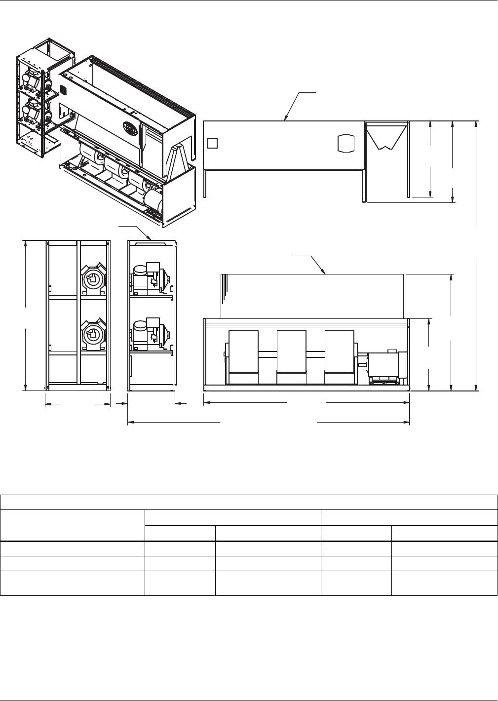
Water-Cooled, Glycol-Cooled and GLYCOOL Systems
Liebert® DS™120
Figure 94 Disassembly dimensions—Water/glycol/GLYCOOL 105kW (30 ton), downflow, semi-hermetic
or standard scroll compressors with centrifugal and EC fans
Table 90 Component weights—Water/glycol/GLYCOOL 105kW (30 ton), downflow, semi-hermetic and
standard scroll compressors
Dry Weight, Approximate, Including Panels, lb (kg)
Component
Semi-Hermetic Compressor Standard Scroll Compressor *
Water/Glycol GLYCOOL/Dual-Cool Water/Glycol GLYCOOL/Dual-Cool
Compressor Assembly 1320 (600) 1320 (600) 1200 (545) 1200 (545)
Filter and Electric Box Assembly 270 (123) 270 (123) 270 (123) 270 (123)
Blower and Coil Assembly
Forward-Curved Fans 1820 (827) 2180 (991) 1820 (827) 2180 (991)
* Digital scroll compressors not available on DS 105
Source: DPN001060, Rev. 2
DPN001060
Rev. 2
NOTES: Drawing views are simplified with panels removed to show overall dimensions.
See disassembly and handling instructions in installation manual.
Filter & Electric Box Assembly
39"
(991mm)
41-11/16"
(1059mm)
76" (1930mm)
Assembled
Height
37"
(940mm)
59-7/16"
(1510mm)
105"
(2667mm)
131"
(3327mm)
76"
(1930mm)
26"
(660mm)
33"
(838mm)
Assembled Length
Compressor Assembly
Blower & Coil
Assembly
Digital scroll compressors
not available on 105 models
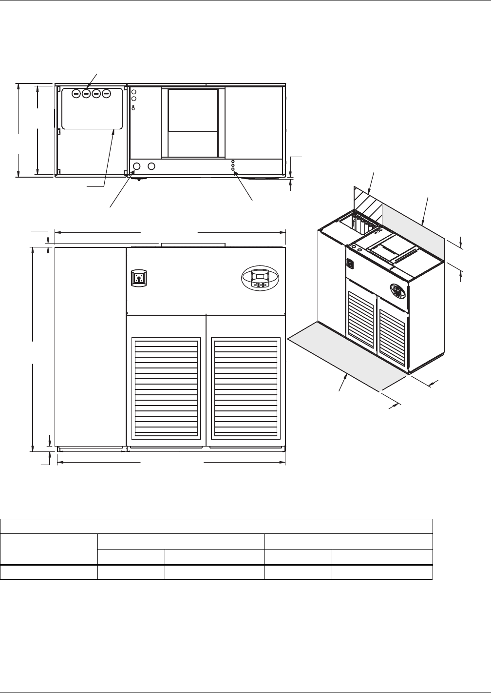
Water-Cooled, Glycol-Cooled and GLYCOOL Systems
121 Liebert® DS™
4.8 DIMENSIONS—LIEBERT DS 028-042, UPFLOW, WATER/GLYCOL/GLYCOOL-COOLED
MODELS
Figure 95 Dimensions—Water/glycol/GLYCOOL, 28-42kW (8-12 ton), upflow, all compressors with
centrifugal fans
Table 91 Weights—Water/glycol/GLYCOOL, 28-42kW (8-12 ton), upflow, all compressors
Dry weight, including panels, lb. (kg)
Semi-Hermetic Compressor Scroll or Digital Scroll Compressor
Water/Glycol GLYCOOL/Dual-Cool Water/Glycol GLYCOOL/Dual-Cool
Forward-Curved Fans 1980 (898) 2130 (966) 1830 (830) 1980 (898)
Source: DPN001164, Rev. 2
DPN001164
Rev. 2
Alternate Condenser
Fluid Piping Entrance
3/4"
(19mm)
Bezels
24"
(610mm)
34"
(864mm)
85" (2159mm)
FRONT VIEW
Shaded area indicates a
recommended minimum
clearance for component
access.
2"
(51mm)
76"
(1930mm)
1-1/2"
(38mm)
TOP VIEW
86" (2184mm)
High-Volt Connection(s)
Condenser Cleanout Access
35"
(889mm)
33"
(838mm)
Minimum required
for blower replacement
Required for
condenser cleanout
Low-Volt Connection(s)
Note: Front air return unit shown. For
rear return unit, in addition to front service
area shown, also include 25" (635mm) on
one side of unit for access to rear return
filter box. See DPN001196.
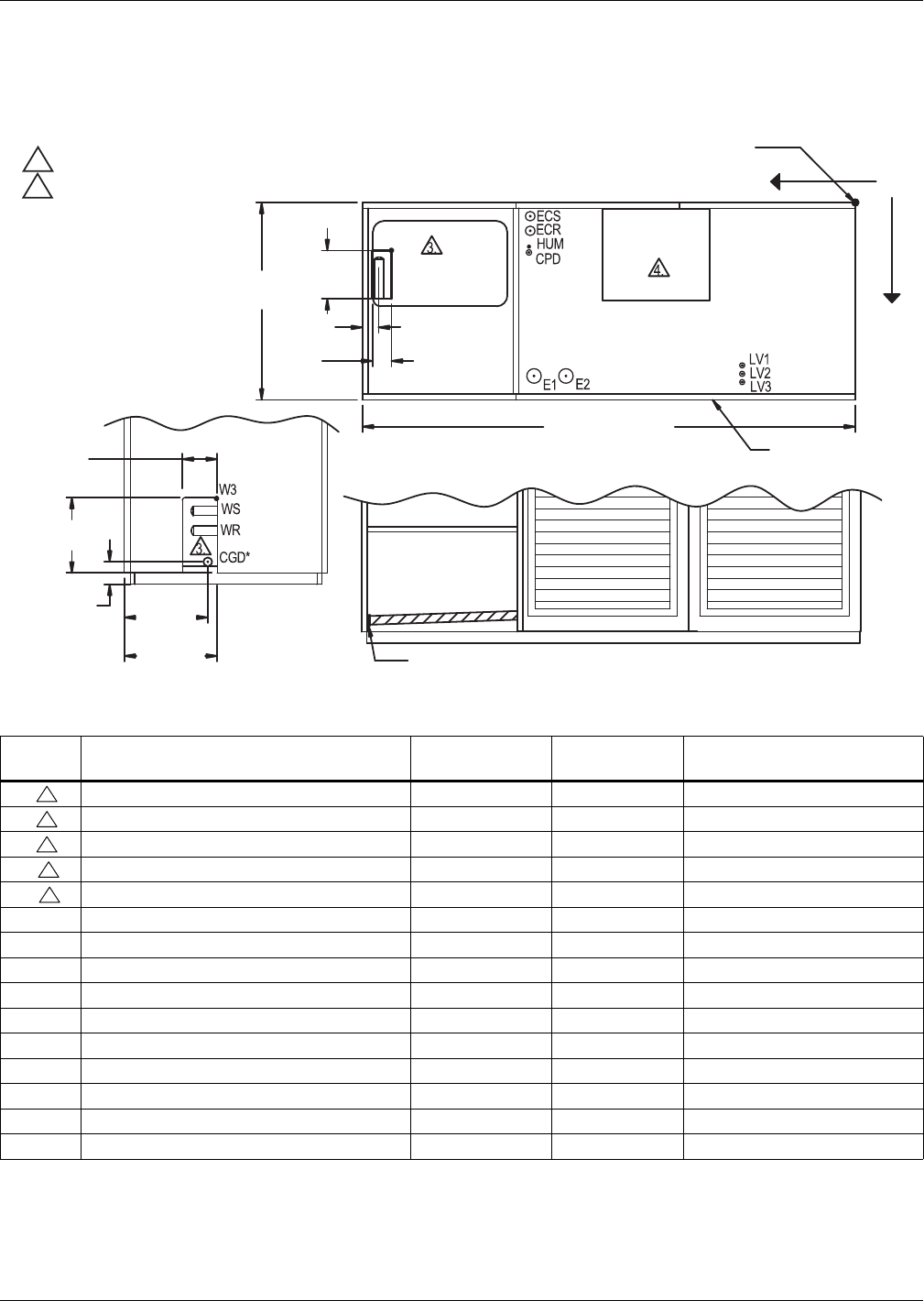
Water-Cooled, Glycol-Cooled and GLYCOOL Systems
Liebert® DS™122
Figure 96 Primary connection locations—Water/glycol/GLYCOOL, 28-42kW (8-12 ton), upflow, all
compressors with centrifugal fans
Table 92 Piping data—Water/glycol/GLYCOOL, 28-42kW (8-12 ton), upflow, all compressors
Point Description
X
in. (mm)
Y
in. (mm)
Connection Size / Opening
in. (mm)
W1 Water/Glycol/GLYCOOL Access (Bottom) 79-15/16 (2030) 9 (229) 3-1/2 3-1/2 x 8 (89 x 203)
W2 Water/Glycol/GLYCOOL Access (Top) 79-15/16 (2030) 9 (229) 3-1/2 x 8 (89 x 203)
W3 Water/Glycol/GLYCOOL Access (Side) — — 6 x 17-3/16 (152 x 437)
WS Water/Glycol/GLYCOOL Supply — — 1-5/8" CU Sweat
WR Water/Glycol/GLYCOOL Return — — 1-5/8" CU Sweat
CGD * Condensate Gravity Drain — — 3/4" FPT
CPD Condensate Pump Discharge (Opt) 56-1/4 (1429) 11-1/8 (282) 1/2" CU Sweat
HUM Humidifier Supply Line 56-1/4 (1429) 9-1/8 (232) 1/4" CU Sweat
ECS ** Dual-Cool Supply 56 (1423) 7-5/16 (186) 1-5/8" CU Sweat
ECR ** Dual-Cool Return 56 (1423) 4-1/2 (114) 1-5/8" CU Sweat
E1 Electrical Conn. (High Volt) 55-3/8 (1407) 30-7/8 (784) 2-1/2"
E2 Electrical Conn. (High Volt) 49-7/8 (1267) 30-7/8 (784) 2-1/2"
LV1 Electrical Conn. (Low Volt) 19-1/2 (495) 29-1/16 (738) 7/8"
LV2 Electrical Conn. (Low Volt) 19-1/2 (495) 30-1/2 (775) 7/8"
LV3 Electrical Conn. (Low Volt) 19-1/2 (495) 31-15/16 (811) 7/8"
* Field pitch condensate drain line a minimum of 1/8" (3.2 mm) per foot (305 mm). All units contain a factory-installed condensate trap. Do
not trap external to the unit. Drain line may contain boiling water. Select appropriate drain system materials. The drain line must comply
with all local codes.
** Supplied on dual-cool systems only (four-pipe system).
Piping dimensions shown are connection sizes; field piping sizes may be different depending on distance. Refer to user manual, SL-18825.
Source: DPN001179, Rev. 3
8"
(203mm)
LEFT SIDE SECTION VIEW OF UNIT
NOTES:
1. Drawing not to scale.
2. Tolerance on all piping dimensions is ± 1/2" (13mm).
3. Field routed alternatives for water/glycol connections.
4. See submittal page DPN001120 for blower outlet and deck
dimensional data.
TOP VIEW OF UNIT
All dimensions from
rear corner of unit
including panels
XO
Y
W1, W2 Blower
Outlet
Front of Unit
86" (2184mm)
FRONT SECTION VIEW OF UNIT
(Left Front Panel Not Shown)
2-7/8"
(73mm)
3-1/2"
(89mm)
35"
(889mm)
3-7/8"
(98mm)
DPN001179
Rev. 3
6"
(152mm)
17-3/16"
(437mm)
15-7/8"
(403mm)
14-1/4"
(362mm)
CGD*
3
3
3
3
3
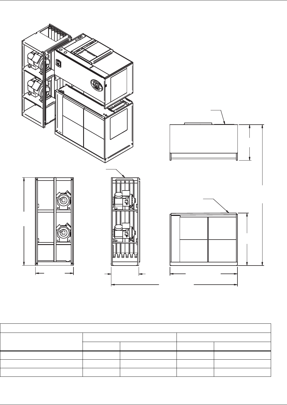
Water-Cooled, Glycol-Cooled and GLYCOOL Systems
123 Liebert® DS™
Figure 97 Disassembly dimensions—Water/glycol/GLYCOOL, 28-42kW (8-12 ton), upflow, all
compressors with centrifugal fans
Table 93 Component weights—Water/glycol/GLYCOOL, 28-42kW (8-12 ton), upflow, all compressors
Dry Weight, Approximate, Including Panels, lb (kg)
Component
Semi-Hermetic Compressor Scroll/Digital Scroll Compressor
Water/Glycol GLYCOOL/Dual-Cool Water/Glycol GLYCOOL/Dual-Cool
Compressor Assembly 950 (432) 950 (432) 800 (364) 800 (364)
Blower and Electric Box Assembly 510 (231) 510 (231) 510 (231) 510 (231)
Filter and Coil Assembly 520 (236) 670 (304) 520 (236) 670 (304)
Source: DPN001173, Rev. 1
DPN001173
Rev. 1
NOTES: Drawing views are simplified with panels removed to show overall dimensions.
See disassembly and handling instructions in installation manual.
31-1/4"
(794mm)
45-13/16"
(1163mm)
76" (1930mm)
Assembled
Height
85" (2159mm)
Assembled Length
59" (1499mm)
26"
(660mm)
33"
(838mm)
76"
(1930mm)
Compressor Assembly
Blower & Electric
Box Assembly
Filter & Coil
Assembly
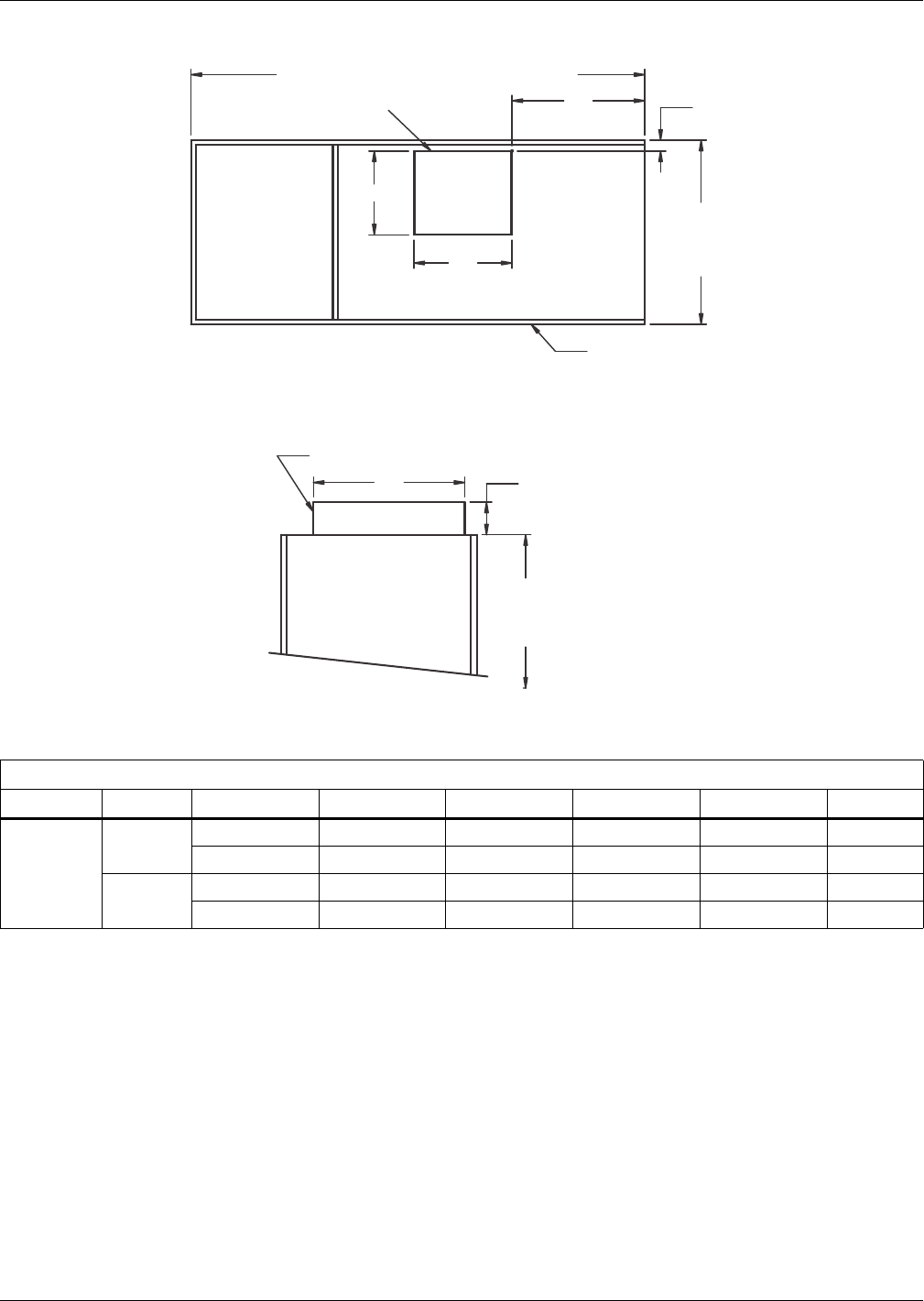
Water-Cooled, Glycol-Cooled and GLYCOOL Systems
Liebert® DS™124
Figure 98 Blower outlet location—28-42kW (8-12 ton), upflow with centrifugal fans
Table 94 Blower outlet and deck dimensions—28-42kW (8-12 ton), upflow
Dimensional data, in. (mm)
Model Blower Supply A B C D E
28-42kW
(8-12ton)
15 x 15 Front Throw 15-7/8 (404) 18-5/8 (472) 2-1/8 (54) 25-5/8 (651) 25 (635)
Rear Throw 15-7/8 (404) 18-5/8 (472) 11-5/8 (295) 25-5/8 (651) 25 (635)
15 x 11 Front Throw 15-7/8 (404) 14-1/2 (368) 2-1/8 (54) 25-5/8 (651) 25 (635)
Rear Throw 15-7/8 (404) 14-1/2 (368) 11-5/8 (295) 25-5/8 (651) 25 (635)
Source: DPN001120, Rev. 3
E C
B
A
D
73" (1854mm) or 86" (2184mm) Ref
35"
(889mm)
Ref
76"
(1930mm)
Ref
1-1/2"
(38mm)
Blower Deck
DPN001120
Rev. 3
Blower Outlet *
* Duct flange not provided
Blower Outlet Location - Top View
Top of Unit
Front or Rear Throw Air Supply
Front of Unit
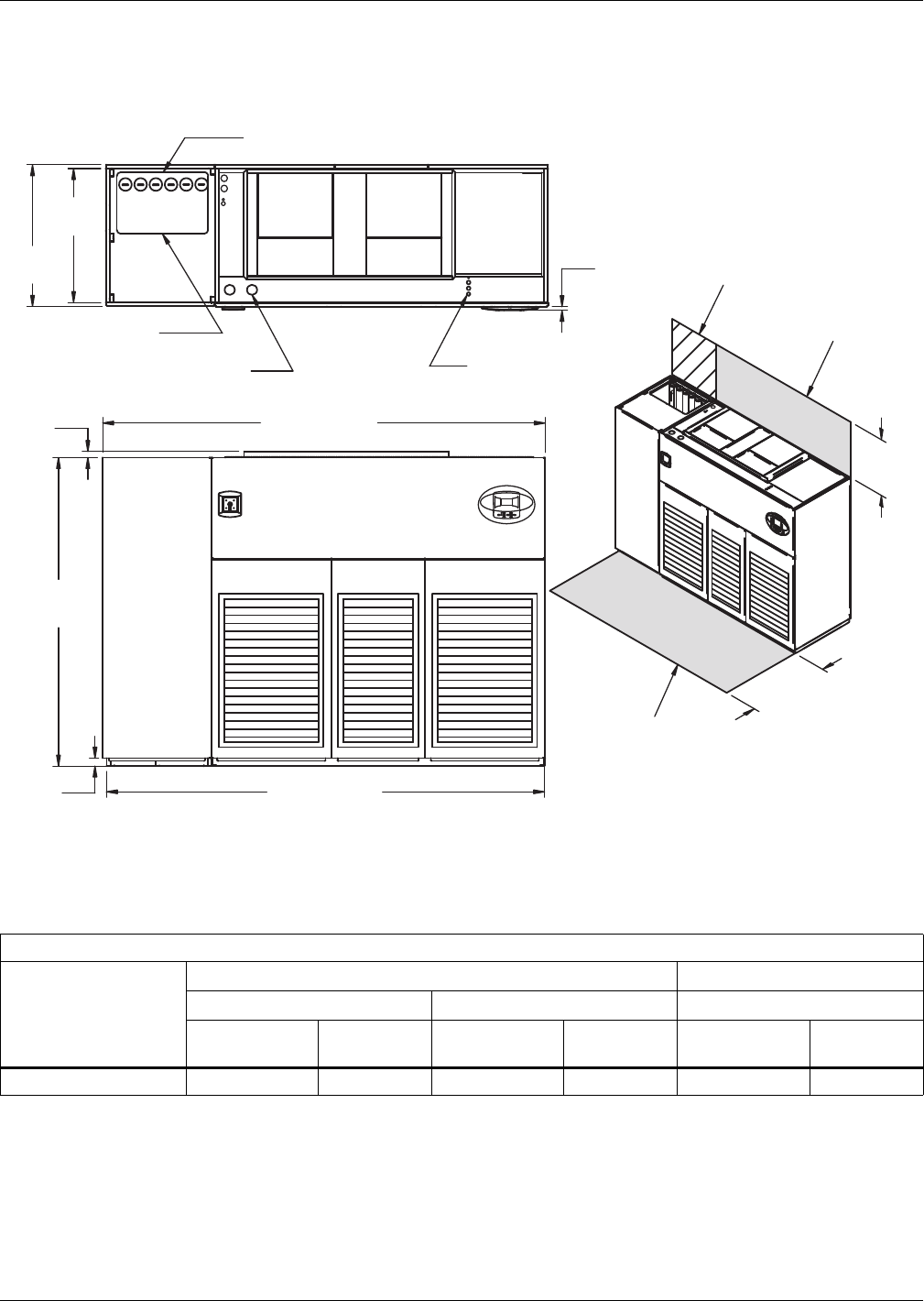
Water-Cooled, Glycol-Cooled and GLYCOOL Systems
125 Liebert® DS™
4.9 DIMENSIONS—LIEBERT DS 053-077, UPFLOW, WATER/GLYCOL/GLYCOOL-COOLED
MODELS
Figure 99 Dimensions—Water/glycol/GLYCOOL, 53-77kw (15-22 ton), upflow, all compressors with
centrifugal fans
Table 95 Weights—Water/glycol/GLYCOOL, 53-77kw (15-22 ton), upflow, all compressors
Dry Weight, Approximate, lb (kg)
Fan Type
Semi-Hermetic Compressor Scroll or Digital Scroll
053 070, 077 053, 070, 077 *
Water/ Glycol
GLYCOOL/
Dual-Cool Water/Glycol
GLYCOOL/
Dual-Cool Water/Glycol
GLYCOOL/
Dual-Cool
Forward-Curved Fans 2650 (1205) 2830 (1287) 2800 (1270) 2980 (1352) 2370 (1075) 2550 (1157)
* Digital scroll compressors not available on DS 077
Source: DPN001167, Rev. 2
33"
(838mm)
NOTE: Front air return unit shown. For rear return unit, in addition to front service
area shown, also include 25" (635mm) on one side of unit for access to rear
return filter box. See DPN001196.
1-1/2"
(38mm)
TOP VIEW
High-Volt Connection(s)
Alternate Condenser
Fluid Piping Entrance
Low-Volt
Connection(s)
FRONT VIEW
DPN001167
Rev. 2
3/4"
(19mm) Bezels
35"
(889mm)
76"
(1930mm)
2"
(51mm)
109" (2769mm)
108" (2743mm)
Shaded area indicates a
recommended minimum
clearance for component access.
24"
(610mm)
34"
(864mm)
Minimum required
for blower replacement
Required for
condenser cleanout
Condenser Cleanout Access
Digital scroll compressors
not available on 077 models.
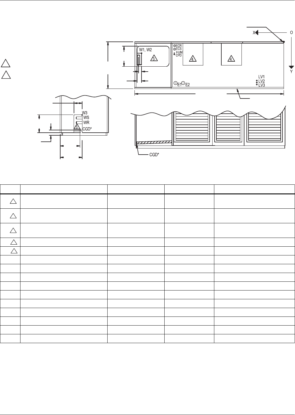
Water-Cooled, Glycol-Cooled and GLYCOOL Systems
Liebert® DS™126
Figure 100 Primary connection locations—Water/glycol/GLYCOOL, 53-77kw (15-22 ton), upflow with
centrifugal fans
Table 96 Piping data—Water/glycol/GLYCOOL, 53-77kw (15-22 ton), upflow
Point Description X, in. (mm) Y, in. (mm) Connection Size / Opening
W1 Water/Glycol/GLYCOOL
Access (Bottom) 102-15/16 (2615) 9 (229) 3-1/2 x 8 (89 x 203)
W2 Water/Glycol/GLYCOOL
Access (Top) 102-15/16 (2615) 9 (229) 3-1/2 x 8 (89 x 203)
W3 Water/Glycol/GLYCOOL
Access (Side) — — 6 x 17-3/16 (152 x 437)
WS Water/Glycol/GLYCOOL Supply — — 2-1/8" Cu Sweat
WR Water/Glycol/GLYCOOL Return — — 2-1/8" Cu Sweat
CGD* Condensate Gravity Drain — — 3/4" FPT
CPD Condensate Pump Discharge (Opt) 79-5/16 (2015) 11-7/8 (302) 1/2" Cu Sweat
HUM Humidifier Supply Line 79-5/16 (2015) 9-7/8 (251) 1/4" Cu Sweat
ECS Dual-Cool Supply 78-5/8 (1998) 7-7/8 (200) 2-1/8" Cu Sweat
ECR Dual-Cool Return 78-5/8 (1998) 4-5/8 (117) 2-1/8" Cu Sweat
E1 Electrical Conn. (High Volt) 75-3/8 (1915) 30 (762) 2-1/2"
E2 Electrical Conn. (High Volt) 69-7/8 (1775) 30 (762) 2-1/2"
LV1 Electrical Conn. (Low Volt) 19-1/2 (495) 29-1/16 (738) 7/8"
LV2 Electrical Conn. (Low Volt) 19-1/2 (495) 30-1/2 (775) 7/8"
LV3 Electrical Conn. (Low Volt) 19-1/2 (495) 31-15/16 (811) 7/8"
* Field pitch condensate drain line a minimum of 1/8" (3.2 mm) per foot (305 mm). All units contain a factory installed condensate trap. Do not
trap external to the unit. Drain line may contain boiling water. Select appropriate drain system materials. The drain line must comply with all
local codes.
** Supplied on dual-cool systems only.
Piping dimensions shown are connection sizes; field piping sizes may be different depending on distance. Refer to user manual, SL-18825.
Source: DPN001214, Rev. 1
NOTES:
1. Drawing not to scale.
2. Tolerance on all piping dimensions
is ± 1/2" (13mm).
3. Field routed alternatives for water/glycol
connections.
4. See submittal page DPN001191 for
blower outlet and deck dimensional data.
6"
(152mm)
DPN001214
Rev. 1
LEFT SIDE SECTION VIEW OF UNIT
FRONT SECTION VIEW OF UNIT
(Left Front Panel Not Shown)
14-1/4"
(362mm)
15-7/8"
(403mm)
3-7/8"
(98mm)
17-3/16"
(437mm)
TOP VIEW OF UNIT
All dimensions from
rear corner of unit
including panels
35"
(889mm)
109" (2769mm)
3-1/2"
(89mm)
8"
(203mm)
2-7/8"
(73mm)
Front of Unit
Blower
Outlet
Blower
Outlet
3
3
3
3
3
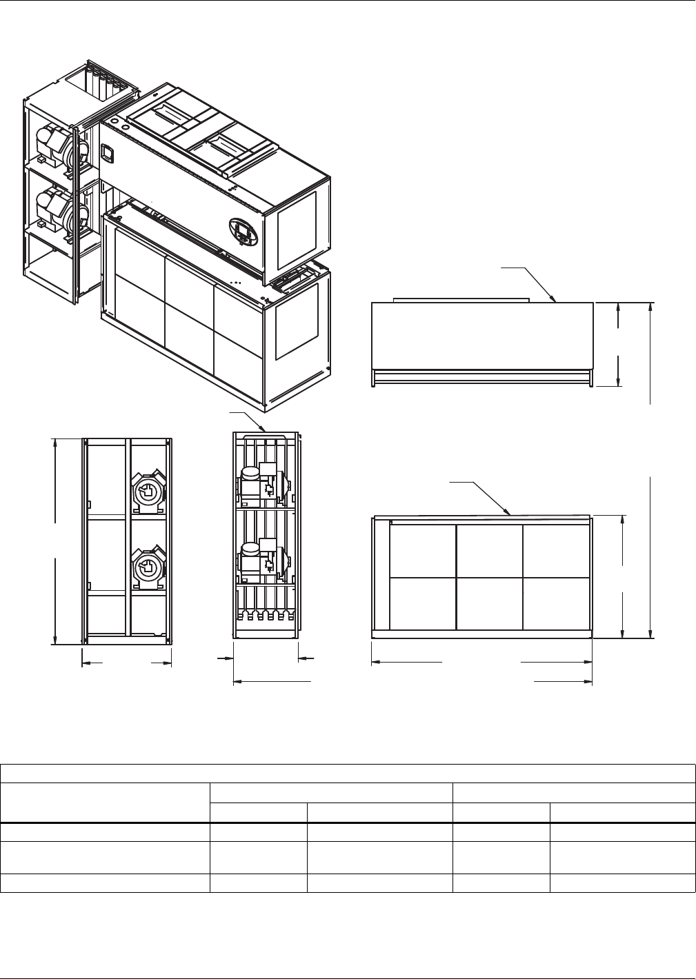
Water-Cooled, Glycol-Cooled and GLYCOOL Systems
127 Liebert® DS™
Figure 101 Disassembly dimensional data—Water/glycol/GLYCOOL, 53-77kw (15-22 ton), upflow, all
compressors with centrifugal fans
Table 97 Component weights—Water/glycol/GLYCOOL, 53-77kw (15-22 ton), upflow, all compressors
Dry Weight, Approximate, Including Panels, lb (kg)
Component
Semi-Hermetic Compressor Scroll or Digital Scroll Compressor *
Water/Glycol GLYCOOL/Dual-cool Water/Glycol GLYCOOL/Dual-Cool
Compressor Assembly 1270 (578) 1270 (578) 840 (382) 840 (382)
Blower and Electric Box Assembly
Forward-Curved Fans 770 (349) 770 (349) 770 (349) 770 (349)
Filter and Coil Assembly 760 (345) 940 (426) 760 (345) 940 (426)
* Digital scroll compressors not available on DS 077
Source: DPN001211, Rev. 1
82" (2083mm)
NOTES: Drawing views are simplified with panels removed to show overall dimensions.
See disassembly and handling instructions in installation manual.
33"
(838mm)
76"
(1930mm)
DPN001211
Rev. 1
26"
(660mm)
Compressor Assembly
Blower & Electric
Box Assembly
Filter & Coil
Assembly
45-13/16"
(1163mm)
31-1/4"
(794mm)
76"
(1930mm)
Assembled
Height
108" (2743mm) Assembled Length
Digital scroll compressors
not available on 077 models.
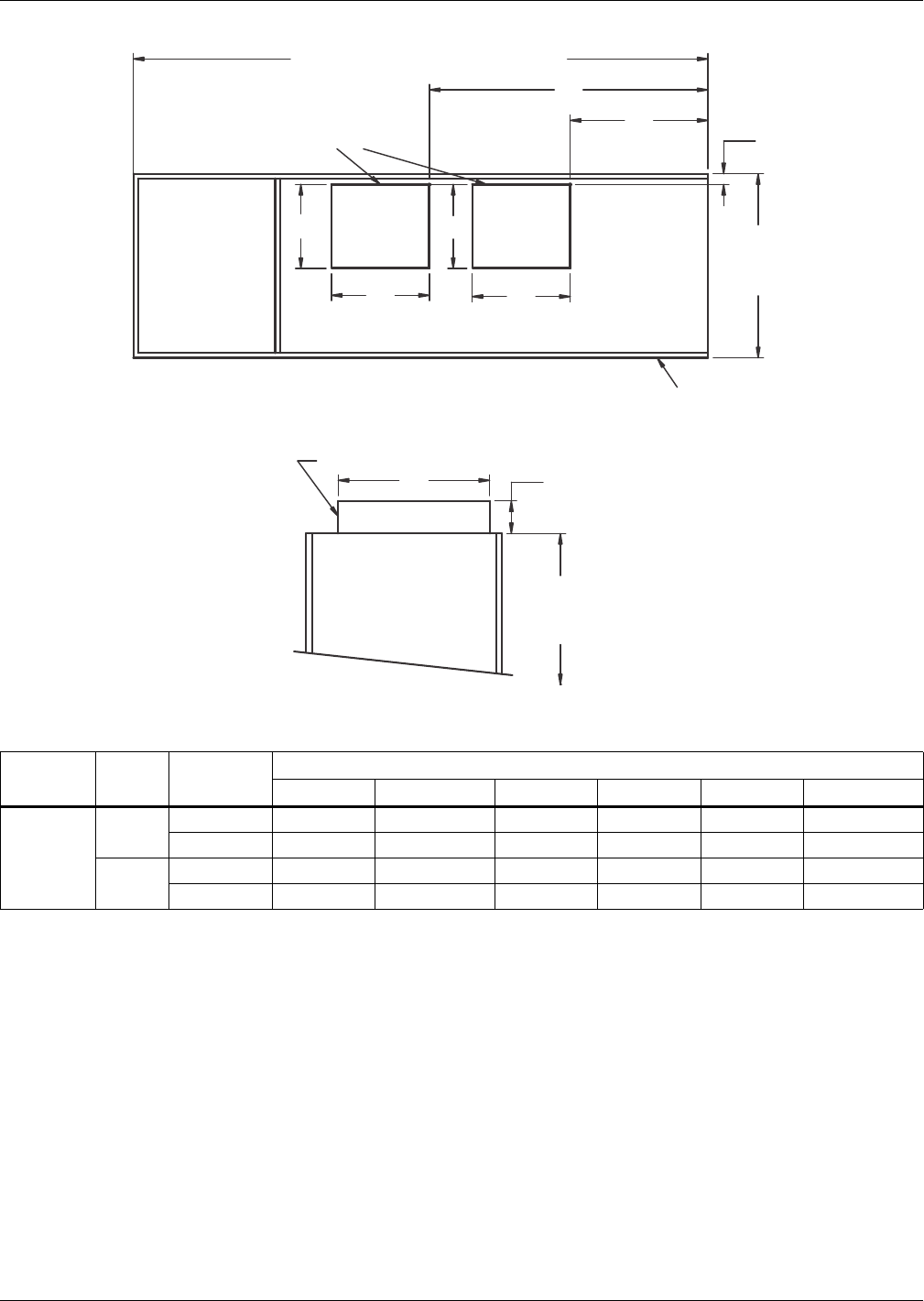
Water-Cooled, Glycol-Cooled and GLYCOOL Systems
Liebert® DS™128
Figure 102 Blower outlet and deck dimensions—53-77kW (15-22 ton), upflow, with centrifugal fans
Table 98 Blower outlet and deck dimensions—53-77kW (15-22 ton), upflow, forward-curved fans
Models Blower Supply
Dimensional Data, in. (mm)
ABCDEF
53-77kW
(15-22 ton)
15 x 15 Front Throw 15-7/8 (404) 18-5/8 (472) 2-1/8 (54) 25-5/8 (651) 27-3/4 (705) 55-1/2 (1410)
Rear Throw 15-7/8 (404) 18-5/8 (472) 11-5/8 (295) 25-5/8 (651) 27-3/4 (705) 55-1/2 (1410)
15 x 11 Front Throw 15-7/8 (404) 14-11/16 (373) 2-1/8 (54) 25-5/8 (651) 31-3/8 (797) 58-7/16 (1484)
Rear Throw 15-7/8 (404) 14-11/16 (373) 11-5/8 (295) 25-5/8 (651) 31-3/8 (797) 58-7/16 (1484)
Source: DPN001191, Rev. 6
Front or Rear Air Throw Supply
Blower Deck 1-1/2"
(38mm)
76"
(1930mm)
Ref.
DPN001191
Rev. 6
Blower Outlets *
98" (2449mm) or 109" (2769mm)
* Duct flanges not provided.
Blower Outlet Location - Top View
35"
(889mm)
Ref
Front of Unit
Top of Unit
B
C
E
F
B
AA
D
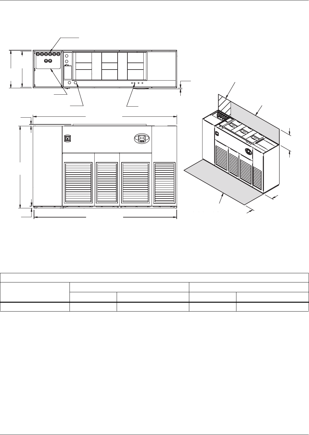
Water-Cooled, Glycol-Cooled and GLYCOOL Systems
129 Liebert® DS™
4.10 DIMENSIONS—LIEBERT DS 105, UPFLOW, WATER/GLYCOL/GLYCOOL MODELS
Figure 103 Dimensions—Water/glycol/GLYCOOL,105kW (30 ton), upflow, semi-hermetic and standard
scroll compressors with centrifugal fans
Table 99 Weights—Water/glycol/GLYCOOL,105kW (30 ton), upflow, semi-hermetic and standard scroll
compressors *
Dry Weight, Approximate, lb (kg)
Fan Type
Semi- Hermetic Compressor Standard Scroll Compressor
Water/Glycol GLYCOOL/Dual-Cool Water/Glycol GLYCOOL/Dual-Cool
Forward-Curved Fans 3370 (1529) 3700 (1678) 3250 (1474) 3580 (1624)
* Digital scroll compressors not available on DS 105
Source: DPN001169, Rev. 1
DPN001169
Rev. 1
FRONT VIEW
TOP VIEW
High-Volt Connection(s)
Alternate Condenser
Fluid Piping Entrance
Alternate Refrigerant
Piping Entrance
Low-Volt Connection(s)
Shaded area indicates a
recommended minimum
clearance for component
access.
Minimum required
for blower replacement
Required for
condenser cleanout
Note: Front air return unit shown. For rear return unit, in addition to front
service area shown, also include 25" (635mm) on one side of unit
for access to rear return filter box. See DPN001196.
34"
(864mm)
24"
(610mm)
3/4"
(19mm)
Bezels
33"
(838mm)
35"
(889mm)
2"
(51mm)
76"
(1930mm)
1-1/2"
(38mm)
131" (3327mm)
132" (3353mm)
Digital scroll compressors
not available on 105 models.
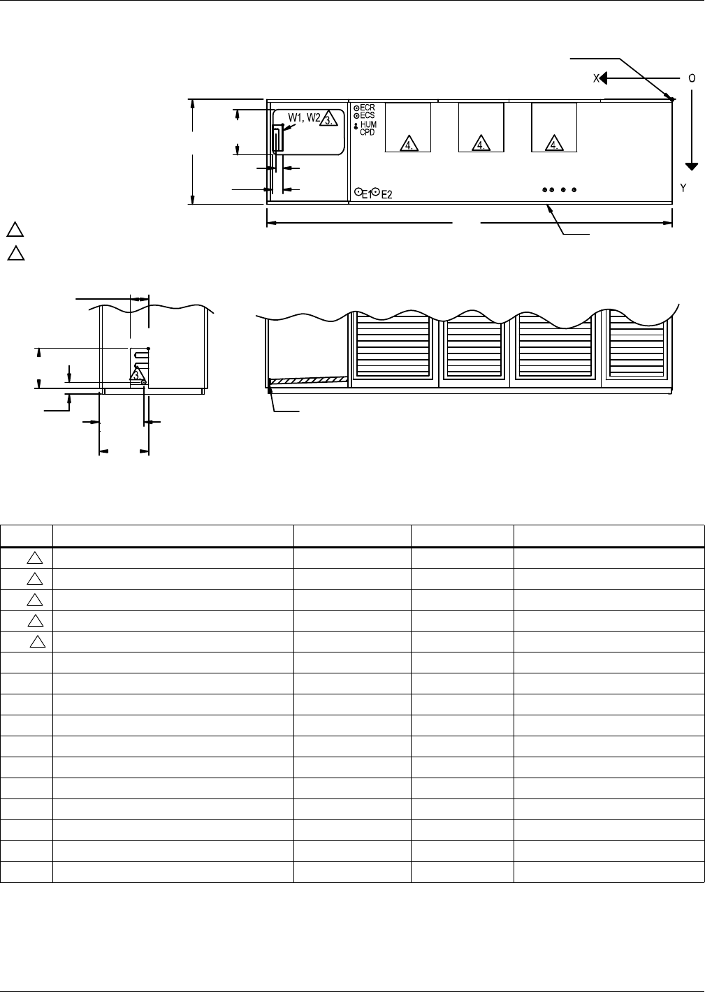
Water-Cooled, Glycol-Cooled and GLYCOOL Systems
Liebert® DS™130
Figure 104 Primary connection locations—Water/glycol/GLYCOOL,105kW (30 ton), upflow with centrifugal
fans
Table 100 Piping data—Water/glycol/GLYCOOL,105kW (30 ton), upflow
Point Description X Y Connection Size/ Opening
W1 Water/Glycol/GLYCOOL Access (Bottom) 126-1/8" (3204mm) 9" (229mm) 3-1/2" x 8" (89mm x 203mm)
W2 Water/Glycol/GLYCOOL Access (Top) 126-1/8" (3204mm) 9" (229mm) 3-1/2" x 8" (89mm x 203mm)
W3 Water/Glycol/GLYCOOL Access (Side) — — 6" x 17-3/16" (152mm x 437mm)
WS Water/Glycol/GLYCOOL Supply — — 2-1/8" Cu Sweat
WR Water/Glycol/GLYCOOL Return — — 2-1/8" Cu Sweat
CGD* Condensate Gravity Drain — — 3/4" FPT
CPD Condensate Pump Discharge (Opt) 102-3/8" (2600mm) 13-5/8" (346mm) 1/2" Cu Sweat
HUM Humidifier Supply Line 101-1/8" (2569mm) 13-1/8" (333mm) 1/4" Cu Sweat
ECS Dual-Cool Supply 101-1/8" (2569mm) 10-1/4" (260mm) 2-5/8" Cu Sweat
ECR Dual-Cool Return 101-1/8" (2569mm) 5-1/4" (133mm) 2-5/8" Cu Sweat
E1 Electrical Conn. (High Volt) 98-1/2" (2502mm) 30" (762mm) 2-1/2"
E2 Electrical Conn. (High Volt) 93" (2362mm) 30" (762mm) 2-1/2"
LV1 Electrical Conn. (Low Volt) 41-1/8" (1045mm) 30-3/8" (772mm) 7/8"
LV2 Electrical Conn. (Low Volt) 38-7/8" (987mm) 30-3/8" (772mm) 7/8"
LV3 Electrical Conn. (Low Volt) 35-1/8" (892mm) 30-3/8" (772mm) 7/8"
LV4 Electrical Conn. (Low Volt) 31-5/8" (803mm) 30-3/8" (772mm) 7/8"
* Field pitch condensate drain line a minimum of 1/8" (3.2 mm) per foot (305 mm). All units contain a factory-installed condensate trap. Do not
trap external to the unit. Drain line may contain boiling water. Select appropriate drain system materials. The drain line must comply with all
local codes.
Piping dimensions shown are connection sizes; field piping sizes may be different depending on distance. Refer to user manual, SL-18825.
Source: DPN001258, Rev. 0
TOP VIEW OF UNIT
Blower
Outlet
Blower
Outlet
Blower
Outlet
CGD*
WR
WS
W3
LV1
LV2
LV3
LV4
6"
(152mm)
FRONT SECTION VIEW OF UNIT
(Left Front Panel Not Shown)
LEFT SIDE SECTION VIEW OF UNIT
All dimensions from
rear corner of unit
including panels
Front Of Unit
DPN001258
Rev. 0
3-7/8"
(98mm)
17-3/16"
(437mm)
CGD*
15-7/8"
(403mm)
8"
(203mm)
14-1/4"
(362mm)
35"
(889mm)
2-7/8"
(73mm)
3-1/2"
(89mm)
132"
(3353mm)
NOTES:
1. Drawing not to scale.
2. Tolerance on all piping dimensions
is ± 1/2" (13mm).
3. Field routed alternatives for water/glycol
connections.
4. See submittal page DPN001192 for
blower outlet and deck dimensional data.
3
3
3
3
3
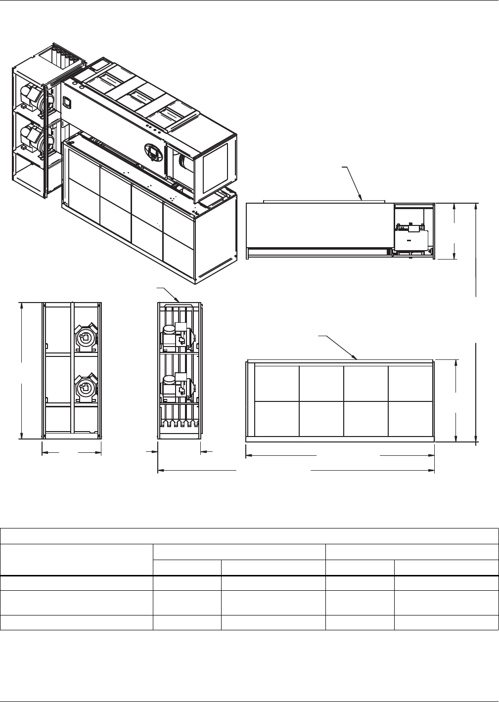
Water-Cooled, Glycol-Cooled and GLYCOOL Systems
131 Liebert® DS™
Figure 105 Disassembly dimensions—Water/glycol/GLYCOOL,105kW (30 ton), upflow, all compressors
with centrifugal fans
Table 101 Component weights—Water/glycol/GLYCOOL,105kW (30 ton), upflow, all compressors
Dry Weight, Approximate, Including Panels, lb (kg)
Component
Semi-Hermetic Compressor Standard Scroll Compressor *
Water/Glycol GLYCOOL/Dual-Cool Water/Glycol GLYCOOL/Dual-Cool
Compressor Assembly 1320 (599) 1320 (599) 1200 (544) 1200 (544)
Blower and Electric Box Assembly
Forward-Curved Fans 1080 (490) 1080 (490) 1080 (490) 1080 (490)
Filter and Coil Assembly 970 (440) 1300 (590) 970 (440) 1300 (590)
* Digital scroll compressors not available on DS 105
Source: DPN001256, Rev. 1
DPN001256
Rev. 1
31-1/4"
(794mm)
33"
(838mm)
76"
(1930mm)
26"
(660mm)
Filter & Coil
Assembly
Compressor
Assembly
Blower & Electric
Box Assembly
NOTES: Drawing views are simplified with panels removed to show overall dimensions.
See disassembly and handling instructions in installation manual.
105" (2667mm)
131" (3327mm
Assembled Length
76"
(1930mm)
Assembled
Height
45-13/16"
(1164mm)
Digital scroll compressors
not available on 105 models.
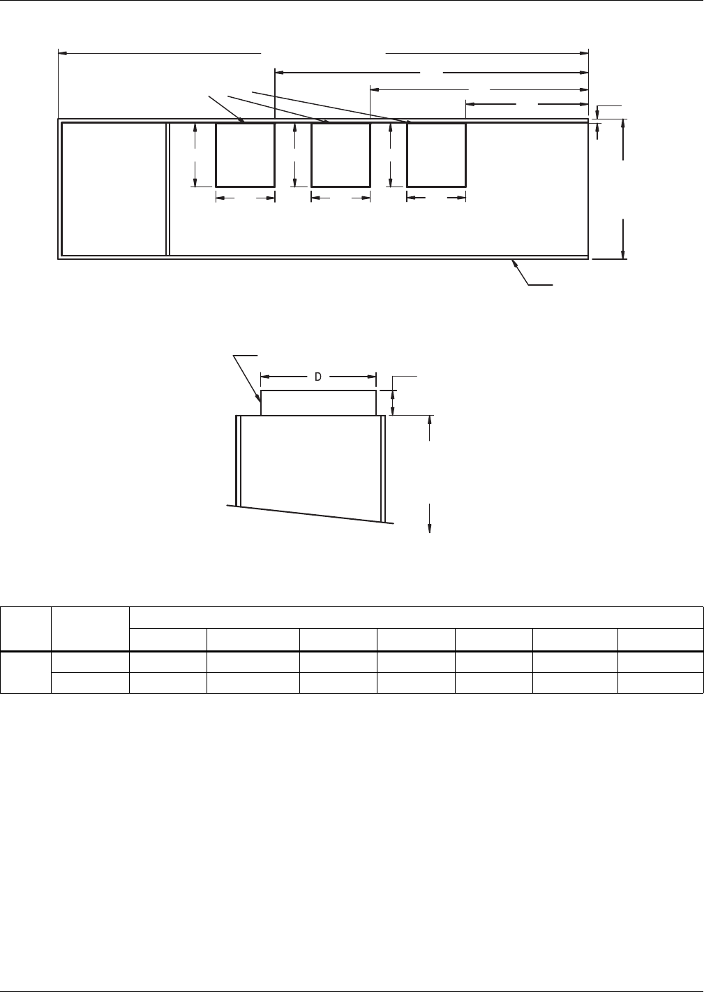
Water-Cooled, Glycol-Cooled and GLYCOOL Systems
Liebert® DS™132
Figure 106 Blower outlet and deck dimensions—105kW (30 ton), upflow with centrifugal fans
Table 102 Blower outlet and deck dimensions—105kW (30 ton), upflow, forward-curved fans
Blower SUPPLY
Dimensional Data, in. (mm)
ABCDE FG
15 x 11 Front Throw 15-7/8 (404) 14-11/16 (373) 2-1/8 (54) 25-5/8 (651) 30-3/4 (781) 54-1/2 (1384) 78-1/8 (1984)
Rear Throw 15-7/8 (404) 14-11/16 (373) 11-5/8 (295) 25-5/8 (651) 30-3/4 (781) 54-1/2 (1384) 78-1/8 (1984)
Source: DPN001192, Rev. 1
76"
(1930mm)
Ref
DPN001192
Rev. 1
1-1/2"
(38mm)
Blower Deck
Front or Rear Throw Air Supply
TOP OF UNIT
Blower Outlets *
BLOWER OUTLET LOCATION - TOP VIEW
35"
(889mm)
Ref
132" (3353mm)
* Duct flanges not provided
Front of Unit
F
EC
A
B
G
A
B
A
B
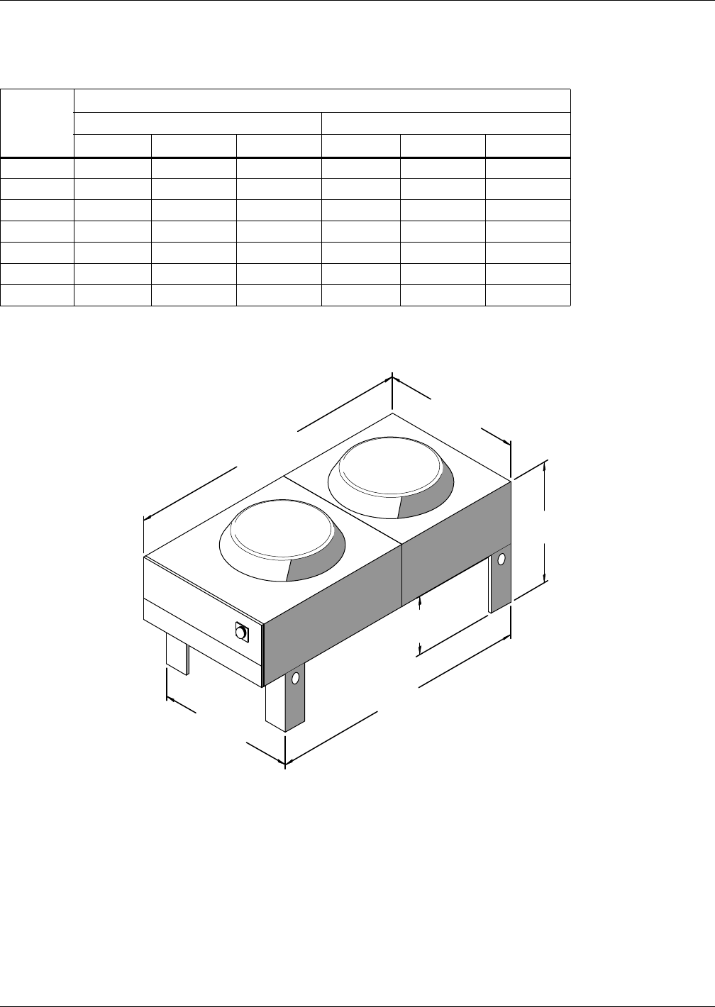
Water-Cooled, Glycol-Cooled and GLYCOOL Systems
133 Liebert® DS™
4.11 HEAT REJECTION—DRYCOOLERS AND PUMPS
4.11.1 Drycooler Selection—Prop Fan Drycoolers
4.11.2 Dimensions—Prop Fan Drycoolers
Figure 107 Dimensions—2-fan fin/tube drycooler models
Table 103 Liebert DS drycooler selection
Liebert DS
Model
Drycooler Type
Outdoor Drycooler Outdoor Quiet-Line Drycooler
95°F (35°C) 100°F (38°C) 105°F (41°C) 95°F (35°C) 100°F (38°C) 105°F (41°C)
028 D-174 D-225-16 D-310-16 D-173-16 D-205-16 D-356-32
035 D-174 D-225-16 D-350-16 D-178-16 D-205-16 D-356-32
042 D-225-16 D-310 D-419 D-205 D-347-32 D-453-32
053 D-260 D-350 D-491-32 DD-248 D-347-32 D-453-32
070 D-310 D-419 D-620-32 D-347-32 D-453-32 D-453-32
077 D-350 D-466 D-650-40 D-347-32 D-453-32 N/A
105 D-466 D-620-32 D-880-52 D-453 N/A N/A
91-1/2"
(2324mm)
43-9/16"
(1106mm)
37-7/8"
(962mm)
18"
(457mm)
84"
(2134mm)
43-3/16"
(1097mm)
Emerson recommends a
clearance of 36" (915mm)
on each side for proper
operation and component
access.
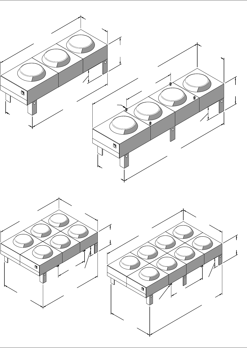
Water-Cooled, Glycol-Cooled and GLYCOOL Systems
Liebert® DS™134
Figure 108 Dimensions—3- and 4-fan fin/tube drycooler models
Figure 109 Dimensions—6- and 8-fan fin/tube drycooler models
Note:
Overall height to the top of fan guard
43-1/8" (1095mm)
Eyebolts
for Lifting
37-7/8"
(962mm)
37-7/8"
(962mm)
171-1/2"
(4356mm)
70"
(1778mm)
131-1/2"
(3340mm)
124"
(3150mm)
164"
(4166mm)
43-3/16"
(1097mm)
43-3/16"
(1097mm)
43-9/16"
(1106mm)
43-9/16"
(1106mm)
18"
(457mm)
18"
(457mm)
Emerson recommends a
clearance of 36" (915mm)
on each side for proper
operation and component
access.
171-1/2"
(4356mm)
37-7/8"
(962mm)
131-1/2"
(3340mm)
18"
(457mm)
70" (1778mm)
86-3/4"
(2203mm)
86-3/4"
(2203mm)
124"
(3150mm)
164"
(4166mm)
Overalll height to the top
of the fan guard is 43-1/8” (1095mm).
1-1/2" (38mm)
diameter hole for
rigging (typ.4)
87-1/8"
(2213mm)
87-1/8"
(2213mm)
18"
(457mm)
59"
(1499mm)
37-7/8"
(962mm)
Emerson recommends a
clearance of 36" (915mm) on
each side for proper
operation and component
Water-Cooled, Glycol-Cooled and GLYCOOL Systems
135 Liebert® DS™
Table 104 Drycooler physical data
Model #
Number
of Fans
Internal
Volume,
gal. (L)
Net Weight
lb. (kg)
-033
1
1.2 (4.6) 390 (177)
-069 2.4 (9.2) 410 (186)
-092 3.7 (13.9) 430 (195)
-109 4.9 (18.6) 450 (204)
-112 5.8 (22.0) 470 (213)
-139
2
4.8 (18.2) 565 (256)
-174 6.9 (26.2) 605 (274)
-197 9 (34) 645 (293)
-225 11.1 (42.1) 685 (310)
-260
3
10.0 (37.8) 826 (375)
-310 13.1 (50.0) 886 (402)
-350 19.4 (73.3) 946 (429)
-352
4
13.1 (49.6) 1040 (471)
-419 17.4 (65.9) 1120 (508)
-466 22.0 (83.3) 1150 (522)
-491 26.3 (99.6) 1200 (544)
-620
6
27.0 (102.2) 1940 (880)
-650 33.0 (124.9) 2000 (907.2)
-700 40.0 (151.4) 2060 (934.4)
-790
8
35.0 (132.5) 2550 (1157)
-880 44.0 (166.5) 2730 (1238.3)
-940 52.0 (196.8) 2910 (1320)
All drycooler fan motors are 3/4 hp.
Table 105 Liebert Quiet-Line™ drycooler physical data
Model #
Number
of Fans
Internal
Volume,
gal. (L)
Net Weight
lb. (kg)
-040
1
2.4 (9.2) 410 (186)
-057 3.7 (13.9) 430 (195)
-060 4.9 (18.6) 450 (204)
-080
2
4.8 (18.2) 565 (256)
-111 6.9 (26.2) 605 (274)
-121 9.0 (34.0) 645 (293)
-158
3
10.0 (37.9) 825 (374)
-173 13.1 (50.0) 885 (401)
-178 19.4 (73.3) 860 (390)
-205 413.1 (50.0) 1070 (485)
-248 17.4 (65.9) 1160 (526)
-347 627.0 (102.2) 1770 (803)
-356 39.3 (148.8) 1890 (857)
-453 835.0 (132.5) 2320 (1052)
-498 52.6 (199.1) 2680 (1216)
Water-Cooled, Glycol-Cooled and GLYCOOL Systems
Liebert® DS™136
4.11.3 Electrical Data—Prop Fan Drycoolers
Table 106 60Hz electrical values—Prop fan drycoolers without pump controls, standard models
Voltage Phase
Drycooler Model
33, 69, 92,
109, 112
1 Fan
139, 174,197
225
2 Fans
260, 310,
350
3 Fans
352, 419, 466,
491
4 Fans
620, 650,
700
6 Fan
790, 880,
940
8 Fans
208/230
1
FLA 4.8 — — — — —
WSA 6.0 — — — — —
OPD 15 — — — — —
3
FLA 3.5 7.0 10.5 14.0 21.0 28.0
WSA 4.4 7.9 11.4 14.9 21.9 28.9
OPD151515202535
460 3
FLA 1.7 3.4 3.4 6.8 10.2 13.6
WSA 2.1 3.8 3.8 7.2 10.6 14.0
OPD151515151520
575 3
FLA 1.4 2.8 4.2 5.6 8.4 11.2
WSA 1.8 3.2 4.6 6.0 8.8 11.6
OPD151515151515
Table 107 60Hz electrical values—Prop fan drycoolers without pump controls, Liebert Quiet-Line models
Voltage Phase
Drycooler Model
40, 57, 60
1 Fan
80, 111, 121
2 Fans
158, 173, 178
3 Fans
205, 248
4 Fans
347, 356
6 Fans
453, 498
8 Fans
208/230
3 FLA 1.8 3.6 10.5 5.4 10.8 14.4
3 WSA 2.3 4.1 11.4 5.9 11.3 14.9
3 OPD 15 15 15 15 15 20
460
3 FLA 0.9 1.8 5.1 2.7 5.4 7.2
3WSA1.12.0 5.52.95.67.4
3 OPD 15 15 15 15 15 15
575
3 FLA 0.7 1.4 4.2 2.1 4.2 5.6
3WSA0.91.6 4.62.34.45.8
3 OPD 15 15 15 15 15 15
Water-Cooled, Glycol-Cooled and GLYCOOL Systems
137 Liebert® DS™
Table 108 60Hz electrical values—Standard prop fan drycoolers with integral pump controls
Model #
Number of Fans
23468
139, 174, 197, 225 260, 310, 350 352, 419, 466, 491 620, 650, 700 790, 880, 940
Pump HP FLA WSA OPD FLA WSA OPD FLA WSA OPD FLA WSA OPD FLA WSA OPD
208/230/3/60
0.75 10.5 11.4 15 14.0 14.9 20 17.5 18.4 25 24.5 25.4 30 31.5 32.4 40
1.5 13.6 15.3 20 17.1 18.8 25 20.6 22.3 25 27.6 29.3 35 34.6 36.3 40
2.0 14.5 16.4 20 18.0 19.9 25 21.5 23.4 30 28.5 30.4 35 35.5 37.4 45
3.0 17.6 20.3 30 21.1 23.8 30 24.6 27.3 35 31.6 34.3 40 38.6 41.3 50
5.0 23.7 27.9 40 27.2 31.4 45 30.7 34.9 50 37.7 41.9 50 44.7 48.9 60
7.5 31.2 37.3 60 34.7 40.8 60 38.2 44.3 60 45.2 51.3 70 52.2 58.3 80
10.0 37.8 45.5 70 41.3 49.0 70 44.8 52.5 80 51.8 59.5 90 58.8 66.5 90
15 53.2 64.8 110 56.7 68.3 110 60.2 71.8 110 67.2 78.8 110 74.2 85.8 125
460/3/60
0.75 5.0 5.4 15 6.7 7.1 15 8.4 8.8 15 11.8 12.2 15 15.2 15.6 20
1.5 6.4 7.2 15 8.1 8.9 15 9.8 10.6 15 13.2 14.0 20 16.6 17.4 20
2.0 6.8 7.7 15 8.5 9.4 15 10.2 11.1 15 13.6 14.5 20 17.0 17.9 20
3.0 8.2 9.4 15 9.9 11.1 15 11.6 12.8 15 15.0 16.2 20 18.4 19.6 25
5.0 11.0 12.9 20 12.7 14.6 20 14.4 16.3 20 17.8 19.7 25 21.2 23.1 30
7.5 14.4 17.2 25 16.1 18.9 25 17.8 20.6 30 21.2 24.0 30 24.6 27.4 35
10.0 17.4 20.9 30 19.1 22.6 35 20.8 24.3 35 24.2 27.7 40 27.6 31.1 45
15 24.4 29.7 50 26.1 31.4 50 27.8 33.1 50 31.2 36.5 50 34.6 39.9 60
575/3/60
0.75 4.1 4.5 15 5.5 5.9 15 6.9 7.3 15 9.7 10.1 15 12.5 12.9 15
1.5 5.2 5.8 15 6.6 7.2 15 8.0 8.6 15 10.8 11.4 15 13.6 14.2 20
2.0 5.5 6.2 15 6.9 7.6 15 8.3 9.0 15 11.1 11.8 15 13.9 14.6 20
3.0 6.7 7.7 15 8.1 9.1 15 9.5 10.5 15 12.3 13.3 15 15.1 16.1 20
5.0 8.9 10.4 15 10.3 11.8 15 11.7 13.2 15 14.5 16.0 20 17.3 18.8 20
7.5 11.8 14.1 20 13.2 15.5 20 14.6 16.9 25 17.4 19.7 25 20.2 22.5 30
10.0 13.8 16.6 25 15.2 18.0 25 16.6 19.4 30 19.4 22.2 30 22.2 25.0 35
15 19.8 24.1 40 21.2 25.5 40 22.6 26.9 40 25.4 29.7 45 28.2 32.5 45
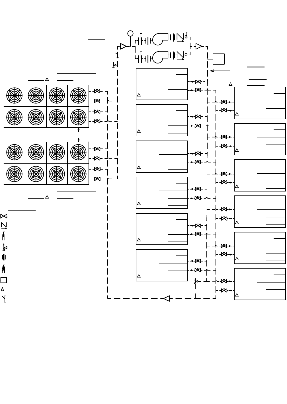
Water-Cooled, Glycol-Cooled and GLYCOOL Systems
Liebert® DS™138
4.11.4 Piping—Prop Fan Drycoolers
Figure 110 Typical piping arrangement, multiple prop fan drycoolers and multiple indoor units
LEGEND
P:
FS
FS
DPN000991
Rev. 0
Gate Valve
Check Valve
Butterfly Valve
Relief Valve
Union
Ball Or Flow Control Valve
Flow Switch
Pressure Drop
Strainer Filter
Cooling Unit #
Model
GPM (L/s)
P Ft (kPa):
Cooling Unit #
Model
GPM (L/s)
P Ft (kPa):
Cooling Unit #
Model
GPM (L/s)
P Ft (kPa):
Cooling Unit #
Model
GPM (L/s)
P Ft (kPa):
Cooling Unit #
Model
GPM (L/s)
P Ft (kPa):
Cooling Unit #
Model
GPM (L/s)
P Ft (kPa):
Cooling Unit #
Model
GPM (L/s)
P Ft (kPa):
Cooling Unit #
Model
GPM (L/s)
P Ft (kPa):
Cooling Unit #
Model
GPM (L/s)
P Ft (kPa):
Cooling Unit #
Model
GPM (L/s)
P Ft (kPa):
Cooling Unit #
Model
GPM (L/s)
P Ft (kPa):
Cooling Unit #
Model
GPM (L/s)
P Ft (kPa):
Expansion Tank
Gal. (L)
Drycooler No. 1 Model
GPM (L/s) P: Ft (kPA)
Drycooler No. 2 Model
GPM (L/s) P: Ft (kPA)
See Note 3
Notes:
1. Pressure and temperature gauges (or ports for same) are recommended to monitor
component pressure drops and performance.
2. Flow measuring devices, drain and balancing valves to be supplied by others and
located as required.
3. See product literature for installation guidelines and clearance dimensions.
4. Drawing shows dual pump package. Alternate pump packages with more pumps may be
considered, consult supplier
To t a l
GPM
(L/s):
Pipe
Diam.: In. (mm)
P: Ft. (kPa)
Water-Cooled, Glycol-Cooled and GLYCOOL Systems
139 Liebert® DS™
Table 109 Standard drycooler piping connection sizes and internal volume
Drycooler
Model #
No. of Internal
Coil Circuits
No. of
Fans
Internal Volume,
gal. (L)
No. of
Inlets/Outlets
Inlet & Outlet Connection Size
OD Copper, in. ID Sweat, in.
033 4*
1
1.2 (4.6) 1/1 1-3/8 —
069 4, 8* 2.4 (9.2) 1/1 1-3/8 —
092 6, 12*, 16 3.7 (13.9) 1/1 1-5/8 —
109 8 4.9 (18.6) 1/1 1-3/8 —
109 16* 1/1 2-1/8 —
112 8 5.8 (22.0) 1/1 1-3/8 —
112 16*, 26 1/1 2-1/8 —
139 8, 16*
2
4.8 (18.2) 1/1 2-1/8 —
174 8, 16*, 24 6.9 (26.2) 1/1 2-1/8 —
197 8, 16*, 32 9 (34) 1/1 2-1/8 —
225 16, 26* 11.1 (42.1) 1/1 2-1/8 —
260 16, 24*
3
10.0 (37.8) 1/1 2-1/8 —
310 16, 32* 13.1 (50.0) 1/1 2-1/8 —
350 16, 32* 19.4 (73.3) 1/1 2-1/8 —
350 48 1/1 2-5/8 —
352 16, 24*
4
13.1 (49.6) 1/1 2-1/8 —
419 16, 32* 17.4 (65.9) 1/1 2-1/8 —
466 26 22.0 (83.3) 1/1 2-1/8 —
466 40* 1/1 25/8 —
491 16 26.3 (99.6) 1/1 2-1/8 —
491 32, 48* 1/1 2-5/8 —
620 32, 64*
6
27.0 (102.2) 2/2 — 2-1/8
650 40, 52* 33.0 (124.9) 2/2 — 2-1/8
650 80 4/4 — 2-1/8
700 32, 64* 40.0 (151.4) 2/2 — 2-1/8
700 96 4/4 — 2-1/8
790 32, 64*
8
35.0 (132.5) 2/2 — 2-1/8
880 52 44.0 (166.5) 2/2 — 2-1/8
880 80* 4/4 — 2-1/8
940 32, 64 52.0 (196.8) 2/2 — 2-1/8
940 96* 4/4 — 2-1/8
* = Standard Circuiting
Water-Cooled, Glycol-Cooled and GLYCOOL Systems
Liebert® DS™140
Table 110 Liebert Quiet-Line drycooler piping connection sizes and internal volume
Drycooler
Model #
No. of Internal
Coil Circuits
No. of
Fans
Internal Volume
gal. (L)
No. of
Inlets/Outlets
Inlet & Outlet Connection Size
OD Copper, in. ID Sweat, in.
040 4, 8*
1
2.4 (9.2) 1/1 1-3/8 —
057 12* 3.7 (13.9) 1/1 1-5/8 —
057 16 1/1 2-1/8 —
060 8 4.9 (18.6) 1/1 1-3/8 —
060 16* 1/1 2-1/8 —
080 8, 16*
2
4.8 (18.2) 1/1 2-1/8 —
111 16*, 24 6.9 (26.2) 1/1 2-1/8 —
121 16*, 32 9.0 (34.0) 1/1 2-1/8 —
158 16, 24*
3
10.0 (37.9) 1/1 2-1/8 —
173 16, 32* 13.1 (50.0) 1/1 2-1/8 —
178 16, 32* 19.4 (73.3) 1/1 2-1/8 —
178 48 1/1 2-5/8 —
205 16, 24* 413.1 (50.0) 1/1 2-1/8 —
248 16, 32* 17.4 (65.9) 1/1 2-1/8 —
347 32, 64*
6
27.0 (102.2) 2/2 — 2-1/8
356 32, 64* 39.3 (148.8) 2/2 — 2-1/8
356 96 4/4 — 2-1/8
453 32, 64*
8
35.0 (132.5) 2/2 — 2-1/8
498 32, 64 52.6 (199.1) 2/2 — 2-1/8
498 96* 4/4 — 2-1/8
* = Standard circuiting
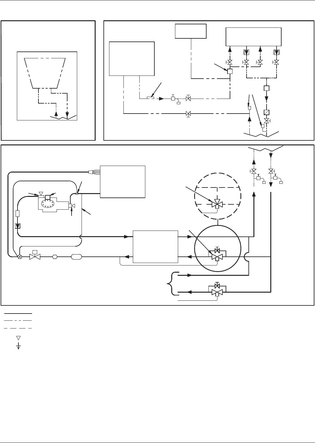
Water-Cooled, Glycol-Cooled and GLYCOOL Systems
141 Liebert® DS™
Figure 111 Piping schematic—Water/glycol semi-hermetic compressor models
DPN000895
Rev. 3
Filter DrierSolenoid
Valve
Expansion
Valve
Sight
Glass
SUCTION
LIQUID
COMPRESSOR
EVAPORATOR
COIL
FACTORY PIPING
OPTIONAL FACTORY PIPING
FIELD PIPING
Service / Schrader (Access) Connection With Valve Core
Service / Schrader (Access) Connection No Valve Core
Sensing Bulb
External
Equalizer
* Components are not supplied by
Emerson but are recommended for
proper circuit operation and
maintenance
** Field-installed at highest point in
system on return line to pumps
*** Locate at tops of all risers and
any intermediate system high points
Bypass Valve
Check
Valve
Service
Valve
* Shutoff Valve
* Shutoff Valve
Service
Valve
* Shutoff Valve * Shutoff Valve
NOTES: Two refrigeration circuits provided.
Single refrigeration circuit shown for clarity.
Schematic representation shown.
Do not use for specific connection locations.
Muffler
DISCHARGE
* Hose
Bib
* Hose
Bib
RETURN
RETURN
RETURN
SUPPLY
SUPPLY
SUPPLY
Two-Way
Regulating
Valve
Sensor
Cylinder
Unloader(s)
LIEBERT DS UNIT
(and associated piping)
CUSTOMER
HEAT REJECTION
LIEBERT
HEAT REJECTION
DRYCOOLER
(Glycol)
GLYCOL
PUMPS
COOLING TOWER
AND PUMP
SYSTEM
BY OTHERS
Aquastat
Sensing
Bulbs
** EXPANSION
TANK
Optional Dual Pump System Shown
* Pressure
Port
* Pressure Port
* Check Valves
(on Dual Pump
Systems only)
* Gate Valves
Flow Switch
Supplied with Dual
Pump Systems
* Flow-Regulating
Valve
PARADENSER
®
CONDENSER
TO SECOND
REFRIGERATION
CIRCUIT
Optional
3-Way
Regulating
Valve
*** Air Vents
(typical)
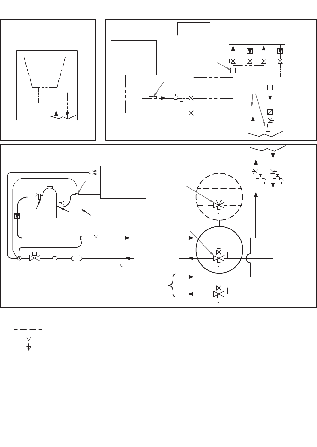
Water-Cooled, Glycol-Cooled and GLYCOOL Systems
Liebert® DS™142
Figure 112 Piping schematic—Water/glycol scroll compressor models
DPN000896
Rev. 3
Filter DrierSolenoid
Valve
Expansion
Valve
Sight
Glass
SUCTION
LIQUID
COMPRESSOR
EVAPORATOR
COIL
FACTORY PIPING
OPTIONAL FACTORY PIPING
FIELD PIPING
Service / Schrader (Access) Connection With Valve Core
Service / Schrader (Access) Connection No Valve Core
Sensing Bulb
External
Equalizer
* Components are not supplied by
Emerson but are recommended for
proper circuit operation and maintenance
** Field-installed at highest point in system
on return line to pumps
*** Locate at tops of all risers and
any intermediate system high points
Bypass Valve
Check
Valve
* Shutoff Valve
* Shutoff Valve
Service
Valve
Service
Valve
* Shutoff Valve * Shutoff Valve
NOTES: Two refrigeration circuits provided.
Single refrigeration circuit shown for clarity.
Schematic representation shown.
This schematic does not imply or define elevations and
component location, unless specifically noted.
DISCHARGE
* Hose
Bib
* Hose
Bib
* Hose
Bib
RETURN
RETURN
RETURN
SUPPLY
SUPPLY
SUPPLY
Two-Way
Regulating
Valve
Sensor
LIEBERT DS UNIT
(and associated piping)
CUSTOMER
HEAT REJECTION
LIEBERT
HEAT REJECTION
DRYCOOLER
(Glycol)
GLYCOL
PUMPS
COOLING TOWER
AND PUMP
SYSTEM
BY OTHERS
Aquastat
Sensing
Bulbs
** EXPANSION
TANK
Optional Dual Pump System Shown
* Pressure
Port
* Pressure Port
* Check Valves
(on Dual Pump
Systems only)
* Gate Valves
Flow Switch
Supplied with Dual
Pump Systems
* Flow-Regulating
Valve
PARADENSER
®
CONDENSER
TO SECOND
REFRIGERATION
CIRCUIT
Optional
3-Way
Regulating
Valve
*** Air Vents
(typical)
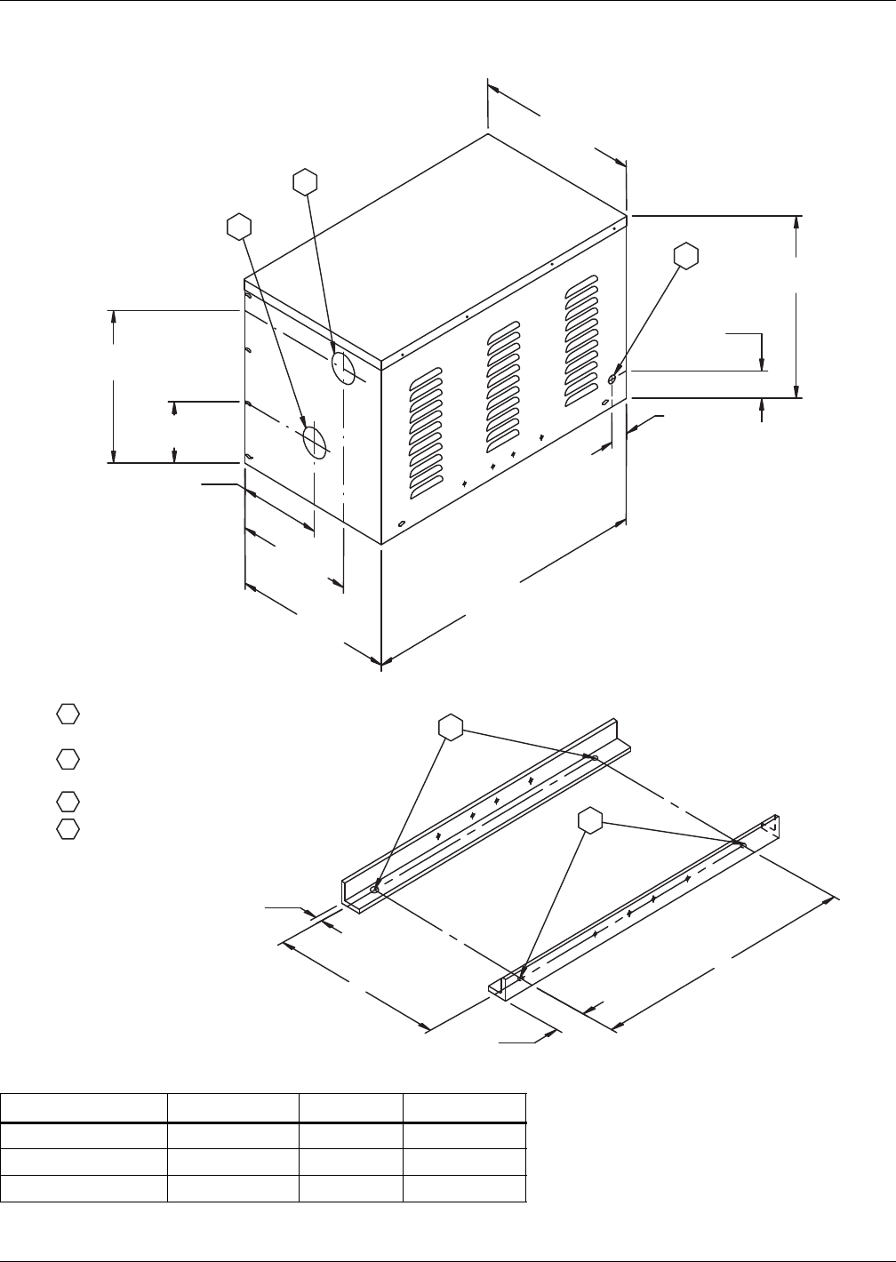
Water-Cooled, Glycol-Cooled and GLYCOOL Systems
143 Liebert® DS™
4.11.5 Pump Packages & Expansion Tank
Figure 113 Single pump package piping connections and dimension
Table 111 Mounting hole dimensions, in. (mm)
Pump Package ABC
Single (0.75 - 7.5hp) 15-1/4 (387.4) 2-1/2 (63.5) 22-1/2 (571.5)
Dual (0.75 - 5hp) 30-1/4 (768.4) 2-1/2 (63.5) 22-1/2 (571.5)
Dual (7.5hp) 39-5/16 (998.5) 1-3/4 (44.5) 26-7/8 (682.6)
Source: DPN000278, Rev. 0
2
1
A
3/4"
(19mm)
4
4
B
C
SINGLE PACKAGE 0.75 - 7.5 HP
PUMP PACKAGE MOUNTING ANGLES
(Angles are inside, bottom
of pump package. View used for
mounting reference.)
19"
(482.6mm)
2-7/8"
(72.9mm)
3
1-3/4"
(44.4mm)
30"
(762mm)
17"
(431.8mm)
12-1/4"
(311.1mm)
6-3/8"
(161.9mm)
15-7/8"
(403.2mm)
8-3/4"
(222.3mm)
17-1/4"
(438.2mm)
3" (76.2mm) diameter pump suction
connection knockouts
3" (76.2mm) diameter pump discharge
connection knockouts
7/8" (22.2mm) diameter electrical knockouts
1/2" (12.7mm) diameter holes for mounting
1
2
3
4
DPN000278
Rev. 0
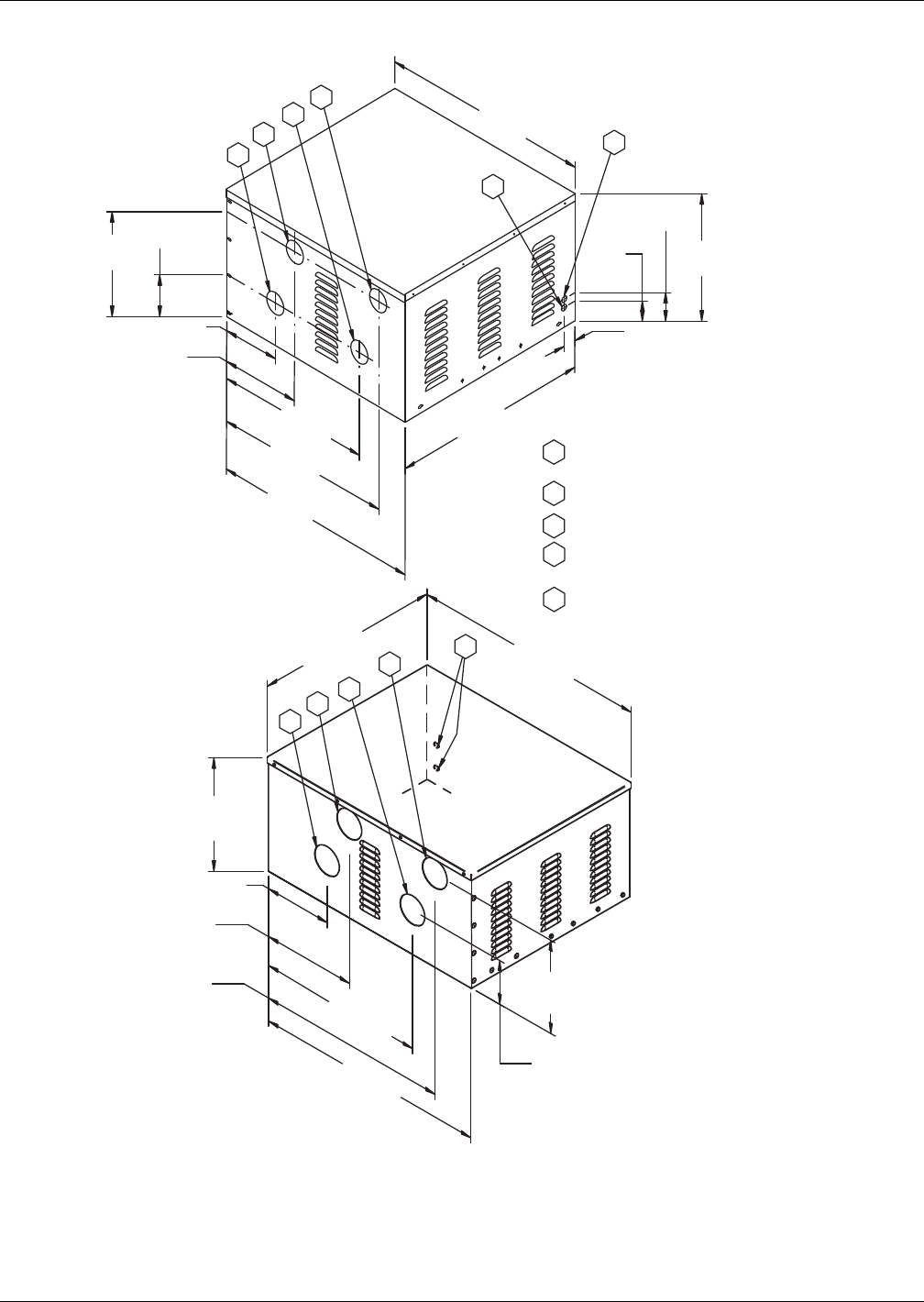
Water-Cooled, Glycol-Cooled and GLYCOOL Systems
Liebert® DS™144
Figure 114 Dual pump package piping connections and dimensions
"
3
3
2
2
1
1
1
2
3
5
6
6
6
5
5
3
3" (76.2mm) diameter pump suction
connection knockouts
3" (76.2mm) diameter pump discharge
connection knockouts
7/8" (22.2mm) diameter electrical knockouts
5" (127mm) diameter pump discharge
connection hole
5" (127mm) diameter pump suction
connection hole
6-1/2"
(165.1mm)
16-3/8"
(415.9mm)
41"
(1041.4mm)
19-15/16
(506.4mm)
11-7/8
(301.6mm)
15-7/8
(403.2mm)
19"
(482.6mm)
1-3/4"
(44.4mm)
30"
(762mm)
8-3/4" (222.2mm)
12-1/4"
(311.1mm)
23-3/4"
(603.2mm)
27-1/4"
(692.1mm)
32-1/4"
(819.2mm)
32"
(812.8mm)
32-3/8"
(822.3mm) 41-1/4"
(1047.8mm)
33-3/16"
(843mm) 29-3/16"
(741.4mm)
15-7/8"
(403.2mm)
6-3/8"
(161.9mm)
DUAL PACKAGE 0.75 - 5 HP
DUAL PACKAGE 7.5 HP
4-1/8"
(104.8mm)
2-7/8"
(73mm)
DPN000328
Rev. 0
See Figure 113 and Table 111 for
mounting angles and dimensions
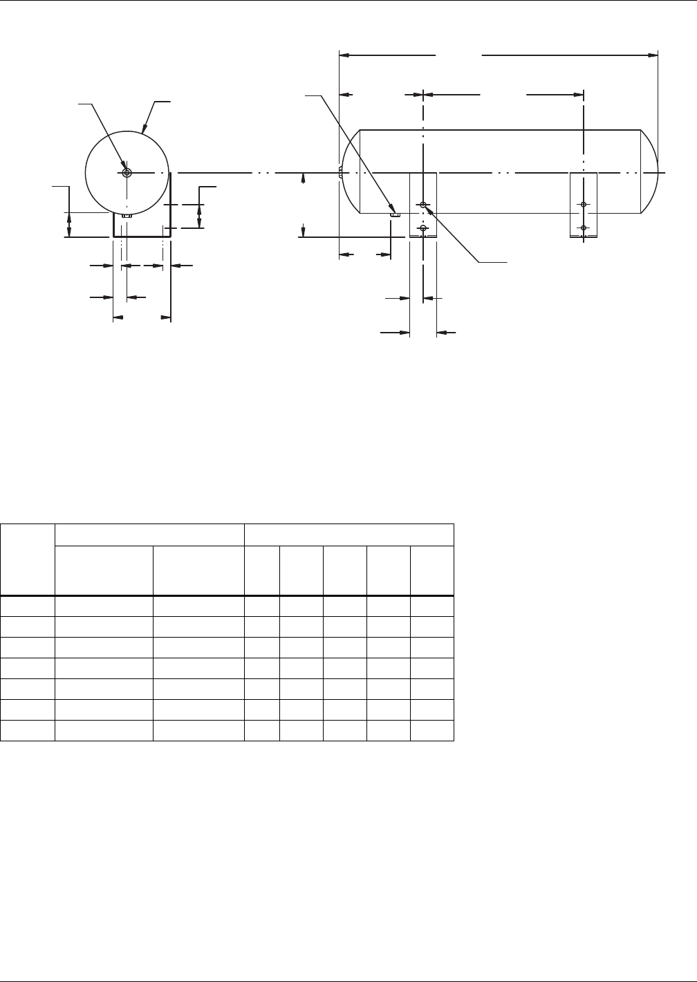
Water-Cooled, Glycol-Cooled and GLYCOOL Systems
145 Liebert® DS™
Figure 115 Pump package expansion tank
Expansion Tank (P/N 1C16717P1)
This tank, included in a standard pump package, has an internal volume of 8.8 gal. (33 l) and a
maximum pressure of 100 psi (690 kPa).
This tank is sized for a typical “open” system with a fluid volume of less than 75 gal. (280l). When
used in a “closed” system, volumes of up to 140 gal. (910l) can be accommodated. The use of a safety
relief valve, field-supplied, is recommended for systems “closed” to atmospheric venting. Other piping
accessories for filling, venting, or adjusting the fluid in the system, are recommended, but not
included.
• To Calculate Total Pump and Drycooler Full Load Amps (FLA):
Total FLA = Pump FLA + Drycooler FLA
• To Calculate Total Pump and Drycooler Wire Size Amps (WSA):
Total WSA = Largest Motor FLA x 1.25 + Sum of other Motor FLA values
• To Calculate Total Pump and Drycooler Maximum Overcurrent Protective Device (OPD):
Total OPD = Largest Motor FLA x 2.25 + Sum of other Motor FLA values
Select standard fuse size (15A, 20A, 25A, 30A, etc.)
Table 112 Glycol pump data
Pump
HP
Connections Electric @ 60Hz
NPT Suction
Connection
Female
Discharge
Connection ph
208
FLA
230
FLA
460
FLA
575
FLA
3/4 1-1/4" 3/4" 1 7.6 6.9 N/A N/A
3/4 1-1/4" 3/4" 3 3.5 3.2 1.6 1.3
1-1/2 1-1/4" 3/4" 3 6.6 6.0 3.0 2.4
2 1-1/4" 3/4" 3 7.5 6.8 3.4 2.7
3 1-1/2" 1" 3 10.6 9.6 4.8 3.9
5 1-1/2" 1-1/4" 3 16.7 15.2 7.6 6.1
7-1/2 3" 3" 3 24.2 22.0 11.0 9.0
DPN000329
Rev. 0
30-1/2"
(774.7mm)
Ø 1/2" (12.7mm)
8 Holes
8.8 gal. (33.3 L)
Expansion Tank
17-1/4"
(438.2mm)
6-13/16"
(173mm)
2-3/4"
(69.9mm)
4"
(101.6mm)
1-1/2"
(38.1mm)
1/2" F.P.T.
Fitting
1/2" F.P.T.
Fitting
Ø 9"
(228.6mm)
2-1/2"
(63.5mm)
1"
(25.4mm)
1"
(25.4mm)
1-1/2"
(38.1mm) 6-1/8"
(155.6mm) 3"
(76.2mm)
7"
(177.8mm)
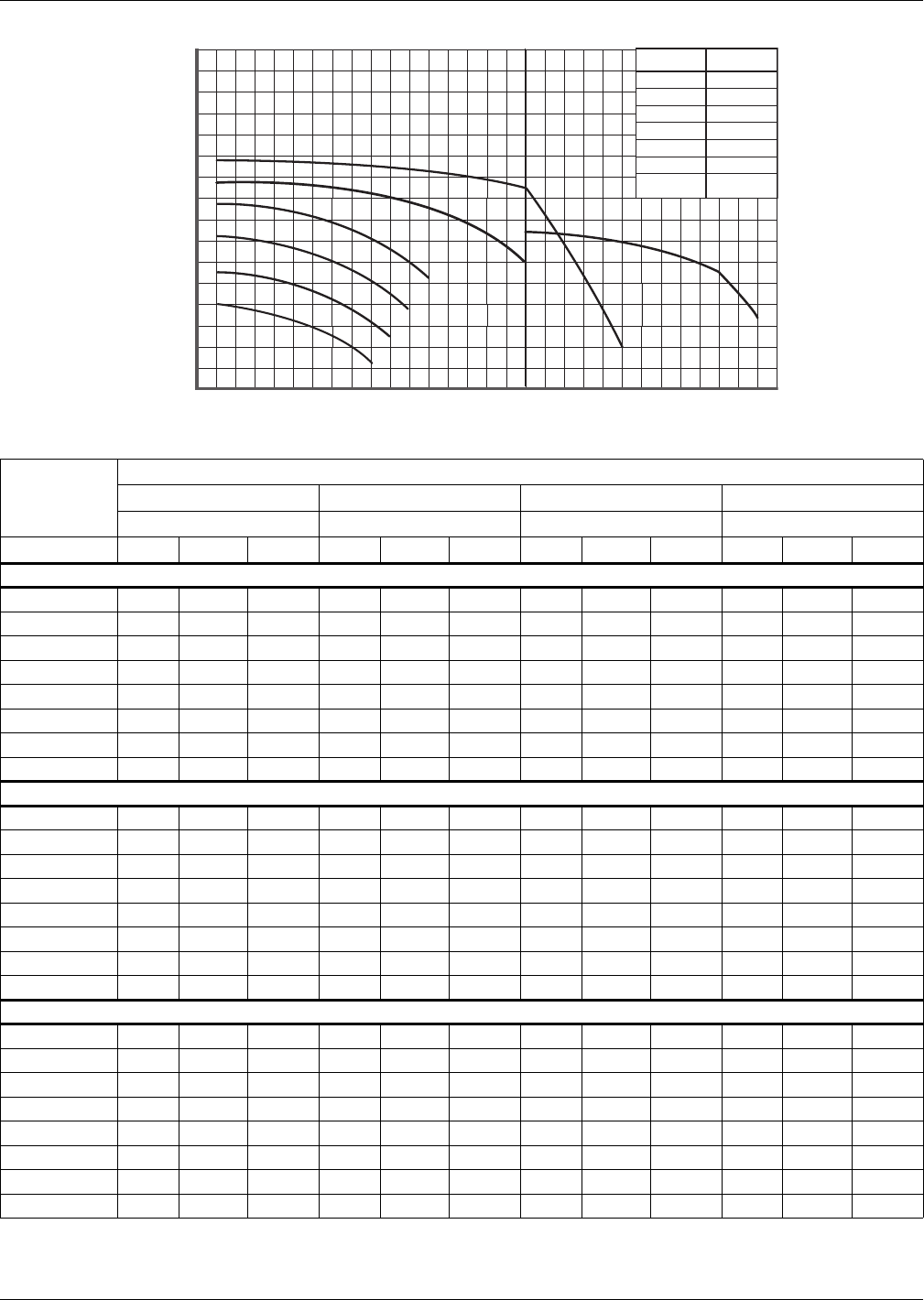
Water-Cooled, Glycol-Cooled and GLYCOOL Systems
Liebert® DS™146
Figure 116 Pump curve, 60 Hz
Table 113 60Hz electrical values—Quiet-Line drycoolers with integral pump controls
Model #
Number of Fans
3468
158, 173, 178 205, 248 347, 356 453, 498
Pump H.P. FLA WSA OPD FLA WSA OPD FLA WSA OPD FLA WSA OPD
208/230/3/60
0.75 8.9 9.8 15.0 10.7 11.6 15.0 14.3 15.2 20.0 17.9 18.8 25.0
1.5 12.0 13.7 20.0 13.8 15.5 20.0 17.4 19.1 25.0 21.0 22.7 25.0
2.0 12.9 14.8 20.0 14.7 16.6 20.0 18.3 20.2 25.0 21.9 23.8 30.0
3.0 16.0 18.7 25.0 17.8 20.5 30.0 21.4 24.1 30.0 25.0 27.7 35.0
5.0 22.1 26.3 40.0 23.9 28.1 40.0 27.5 31.7 45.0 31.1 35.3 50.0
7.5 * 29.6 35.7 50.0 31.4 37.5 60.0 35.0 41.1 60.0 38.6 44.7 60.0
10.0 * 36.2 43.9 70.0 38.0 45.7 70.0 41.6 49.3 80.0 45.2 52.9 80.0
15 * 51.6 63.2 100.0 53.4 65.0 110.0 57.0 68.6 110.0 60.6 72.2 110.0
460/3/60
0.75 4.3 4.7 15.0 5.2 5.6 15.0 7.0 7.4 15.0 8.8 9.2 15.0
1.5 5.7 6.5 15.0 6.6 7.4 15.0 8.4 9.2 15.0 10.2 11.0 15.0
2.0 6.1 7.0 15.0 7.0 7.9 15.0 8.8 9.7 15.0 10.6 11.5 15.0
3.0 7.5 8.7 15.0 8.4 9.6 15.0 10.2 11.4 15.0 12.0 13.2 15.0
5.0 10.3 12.2 15.0 11.2 13.1 20.0 13.0 14.9 20.0 14.8 16.7 20.0
7.5 * 13.7 16.5 25.0 14.6 17.4 25.0 16.4 19.2 30.0 18.2 21.0 30.0
10.0 * 16.7 20.2 30.0 17.6 21.1 35.0 19.4 22.9 35.0 21.2 24.7 35.0
15 * 23.7 29.0 45.0 24.6 29.9 50.0 26.4 31.7 50.0 28.2 33.5 50.0
575/3/60
0.75 3.4 3.7 15.0 4.1 4.4 15.0 5.5 5.8 15.0 6.9 7.2 15.0
1.5 4.5 5.1 15.0 5.2 5.8 15.0 6.6 7.2 15.0 8.0 8.6 15.0
2.0 4.8 5.5 15.0 5.5 6.2 15.0 6.9 7.6 15.0 8.3 9.0 15.0
3.0 6.0 7.0 15.0 6.7 7.7 15.0 8.1 9.1 15.0 9.5 10.5 15.0
5.0 8.2 9.7 15.0 8.9 10.4 15.0 10.3 11.8 15.0 11.7 13.2 15.0
7.5 * 11.1 13.4 20.0 11.8 14.1 20.0 13.2 15.5 20.0 14.6 16.9 25.0
10.0 * 13.1 15.9 25.0 13.8 16.6 25.0 15.2 18.0 25.0 16.6 19.4 30.0
15 * 19.1 23.4 40.0 19.8 24.1 40.0 21.2 25.5 40.0 22.6 26.9 40.0
Values are calculated per UL 1995. Pump FLA values used are based on NEC tables for motor horsepower. OPD values may be adjusted
higher than calculations to compensate for maximum anticipated application temperatures.
* May require electrical component(s) with higher capacity in the drycooler. Consult factory representatives for assistance before ordering.
0
100
120
80
160
180
140
60
40
20
20 30 5010 120 2007040 60 80 160 250 300 400
G
A
B
C
D
E
F
Total Head, Feet/Water
Curve
Flow Rate, GPM
HP
3/4 (1-ph)
3/4 (3-ph)
1.5
2
3
5
7.5
A
B
C
D
E
F
G
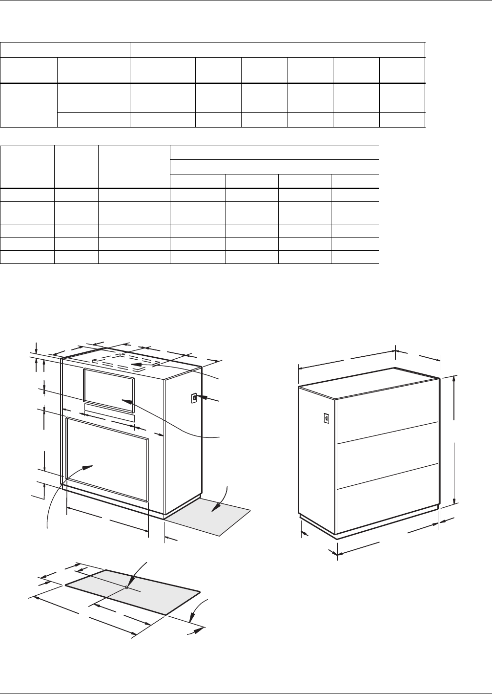
Water-Cooled, Glycol-Cooled and GLYCOOL Systems
147 Liebert® DS™
4.11.6 Drycooler Selection—Indoor Piggyback Drycoolers
4.11.7 Weights and Dimensions—Indoor Piggyback Drycoolers
Figure 117 Dimensions—Indoor piggyback drycoolers
Table 114 Liebert indoor piggyback drycooler/DS matchup data
Drycooler Selections Liebert DS Model
Drycooler
Type
Ambient
Temp. °F (°C) 028 035 042 053 070 077
Piggyback
Drycooler
95 (35) PD-133/150 PD-150 PD-223 PD-290 PD-333 PD-333
100 (38) PD-223 PD-223 PD-333 N/A N/A N/A
105 (41) PD-333 PD-333 PD-333 N/A N/A N/A
Table 115 Indoor piggyback airflow and static pressure data
Model
No.
of Fans CFM (m3/hr)
HP/RPM
Ext. Static Pressure - in. (Pa)
0.25 (62.3) 0.50 (125) 0.75 (187) 1.0 (249)
PD-102 2 6600 (11,200 2/575 3/650 3/725 3/800
PD-133
PD-150 2 6900 (11,730 2/605 3/680 3/750 3/820
PD-223 2 12,500 (21,250 7.5/760 7.5/810 7.5/870 7.5/920
PD-290 2 12,300 (20,910 7.5/780 7.5/830 7.5/890 7.5/940
PD-333 2 16,500 (28,050 10/640 10/695 10/740 15/790
Values are without filter box. External Static Pressure = filter pressure drop + other static drops.
Source: DPN000695, Rev. 0
E
KHJ
K
S
H
J
R
G
C
F
A
UNIT DIMENSIONS
BD
R
Shaded areas indicate
a recommended
clearance of 34" (864mm)
for component access.
Fan Discharge
Floor Level
Drain Outlet
Opening
Optional Fan
Discharge
Disconnect
Switch
FLOOR CUTOUT DIMENSIONS
Rear of
Cabinet
1"
(25.4mm)
A
Unit Base
C
Unit Base
72"
(1829mm)
Overall Dimensions
Overall Dimensions
5"
(127mm)
10"
(254mm)
Condenser Coil Inlet
and Duct Connection
35-1/8"
(892mm)
1-1/8"
(29mm)
15-7/16"
(392mm)
DPN000710
Rev. 1
Note: A 1" (25.4mm) flange is provided
on all units for duct connection
to coil duct opening and fan air
discharge opening.
Water-Cooled, Glycol-Cooled and GLYCOOL Systems
Liebert® DS™148
4.11.8 Electrical Data—Piggyback Drycoolers
Table 116 Dimensions—Indoor piggyback drycoolers, in (mm)
Model ABCDEFG H J K R S
PD-102 72
(1829)
74
(1880)
31
(787)
32
(813)
1-1/8
(29)
33
(838)
60
(1524)
8-5/8
(219)
50-3/16
(1275)
16-1/16
(408)
13-3/16
(335)
14-11/16
(373)
PD-133 72
(1829)
74
(1880)
31
(787)
32
(813)
1-1/8
(29)
33
(838)
60
(1524)
8-5/8
(219)
50-3/16
(1275)
16-1/16
(408)
13-3/16
(335)
14-11/16
(373)
PD-150 72
(1829)
74
(1880)
31
(787)
32
(813)
1-1/8
(29)
33
(838)
60
(1524)
8-5/8
(219)
50-3/16
(1275)
16-1/16
(408)
13-3/16
(335)
14-11/16
(373)
PD-223 97
(2464)
99
(2515)
33
(838)
34
(864)
3-1/8
(79)
46-1/2
(1181)
85
(2159)
23-5/16
(592)
50-3/16
(1275)
16-1/16
(408)
23-1/2
(597)
14-11/16
(373)
PD-290 97
(2464)
99
(2515)
33
(838)
34
(864)
3-1/8
(79)
46-1/2
(1181)
85
(2159)
23-5/16
(592)
50-3/16
(1275)
16-1/16
(408)
23-1/2
(597)
14-11/16
(373)
PD-333 97
(2464)
99
(2515)
33
(838)
34
(864)
3-1/8
(79)
46-1/2
(1181)
85
(2159)
16-5/16
(421)
63-7/8
(1622)
19-1/8
(486)
16-13/16
(427)
11-5/8
(295)
1. A 1" (25.4mm) flange is provided on all units for duct connection to coil duct opening and fan air discharge opening.
2. Source: DPN000710, Rev. 1
Table 117 Electrical data, piggyback drycoolers, 60Hz, 3 Ph
Model Voltage
Blower
Motor HP
Drycooler
No Pumps
Drycooler
Standard Pump Package
Drycooler - Optional
Pump Package
Total Unit Pump Only Total Unit
Pump
Only Total Unit
FLA WSA OPD hp FLA FLA WSA OPD hp FLA WSA OPD
PD-102
PD-133
208 3 10.6 13.3 20 1.5 6.6 17.2 19.9 30 2 18.1 20.8 30
230 3 9.6 12.0 20 1.5 6.0 15.6 18 25 2 16.4 18.8 25
460 3 4.8 6.0 15 1.5 3.0 7.8 9 15 2 8.2 9.4 15
575 3 3.9 4.9 15 1.5 2.4 6.3 7.3 15 2 6.6 7.6 15
PD-150
208 3 10.6 13.3 20 2 7.5 18.1 20.8 30 3 21.2 23.9 30
230 3 9.6 12.0 20 2 6.8 16.4 18.8 25 3 19.2 21.6 30
460 3 4.8 6.0 15 2 3.4 8.2 9.4 15 3 9.6 10.8 15
575 3 3.9 4.9 15 2 2.7 6.6 7.6 15 3 7.8 8.8 15
PD-223
208 7.5 24.2 30.3 50 3 10.6 34.8 40.9 60 5 40.9 47 70
230 7.5 22.0 27.5 45 3 9.6 31.6 37.1 50 5 37.2 42.7 60
460 7.5 11.0 13.8 20 3 4.8 15.8 18.6 25 5 18.6 21.4 30
575 7.5 9.0 11.3 20 3 3.9 12.9 15.2 20 5 15.1 17.4 25
PD-290
208 7.5 24.2 30.3 50 5 10.6 40.9 47 60 3 34.8 40.9 60
230 7.5 22.0 27.5 45 5 9.6 37.2 42.7 30 3 31.6 37.1 50
460 7.5 11.0 13.8 20 5 4.8 18.6 21.4 25 3 15.8 18.6 25
575 7.5 9.0 11.3 20 5 3.9 15.1 17.4 20 3 12.9 15.2 20
PD-333
208 10 30.8 38.5 60 5 10.6 47.5 55.2 80 3 41.4 49.1 70
230 10 28.0 35.0 60 5 9.6 43.2 50.2 70 3 37.6 44.6 70
460 10 14.0 17.5 30 5 4.8 21.6 25.1 35 3 18.8 22.3 35
575 10 11.0 13.8 20 5 3.9 17.1 19.9 30 3 14.9 17.7 25
ph = phase; FLA = Full Load Amps; WSA = Wire Size Amp; OPD = Maximum Overcurrent Protection Device
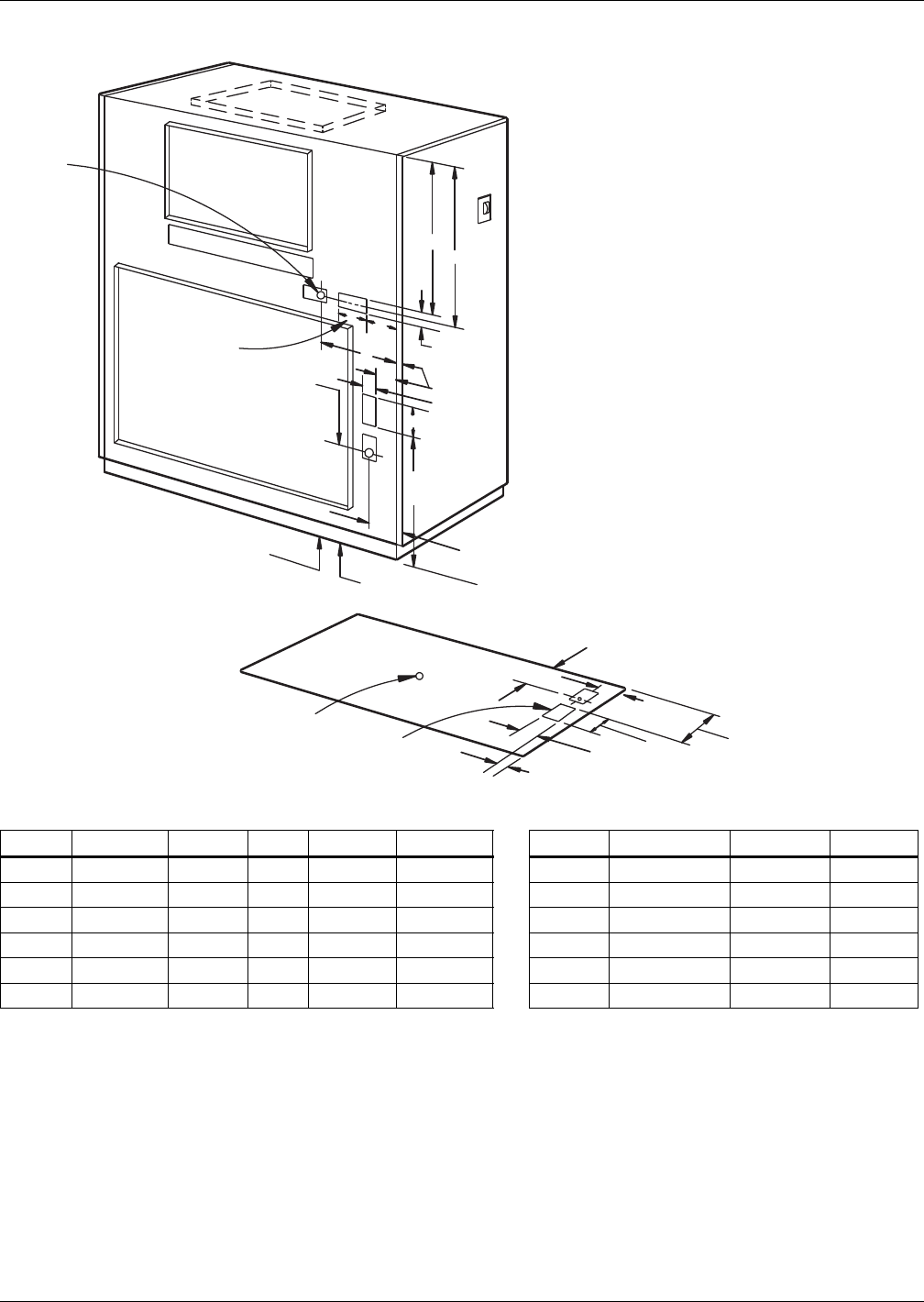
Water-Cooled, Glycol-Cooled and GLYCOOL Systems
149 Liebert® DS™
Figure 118 Piping—Indoor piggyback drycooler models
Table 118 Dimensions—Indoor piggyback drycoolers Table 119 Pipe connection sizes, ODS
Model # A B C D E Model # Glycol Supply Glycol Ret. Drain
PD-102 27-1/4 (692) 1-1/2 (38) 6 (152) 9-1/8 (232) 28-3/4 (730) PD-102 1-5/8 (41) 1-1/4 (32) 1-1/4 (32)
PD-133 27-1/4 (692) 1-1/2 (38) 6 (152) 9-1/8 (232) 28-3/4 (730) PD-133 See Note 3 See Note 3 1-1/4 (32)
PD-150 27-1/4 (692) 1-1/2 (38) 6 (152) 9-1/8 (232) 28-3/4 (730) PD-150 2-1/8 (54) 1-1/4 (32) 1-1/4 (32)
PD-223 27-1/4 (692) 1-1/2 (38) 6 (152) 9-1/8 (232) 28-3/4 (730) PD-223 2-1/8 (54) 1-1/4 (32) 1-1/4 (32)
PD-290 27-1/4 (692) 1-1/2 (38) 6 (152) 9-1/8 (232) 28-3/4 (730) PD-290 2-1/8 (54) 1-1/4 (32) 1-1/4 (32)
PD-333 29-1/2 (749 6 (152) 6 (152) — — PD-333 2-1/8 (54) 1-1/4 (32) 1-1/4 (32)
3"
(76mm)
A
B
C
E
D
C
See Note 1
See Note 1
See Note 2
See Note 2
See Note 2
5-1/2" (140mm)
See Note 1
3" (76mm)
6"
(152mm)
3"
(76mm)
1-1/2"
(38mm)
8"
(203mm)
2-1/2" (64mm)
7-7/8"
(200mm)
9-11/16"
(246mm)
12-5/8"
(321mm)
3" (76mm)
1" (25mm)
Drain Outlet
Location
1-1/4" (32mm) F.P.T.
1. Multiple knockouts of 1-3/8" (35mm), 1-3/4" (45mm)
and 2-1/2" (64mm) for Main Power Supply (Typ).
2. Cover plate for access of glycol piping inlet and outlet.
3. Piggyback drycooler connection sizes for supply and
return glycol lines are the same as room unit supply and return lines.
Note applies to PD-133.
DPN000711
Rev. 0
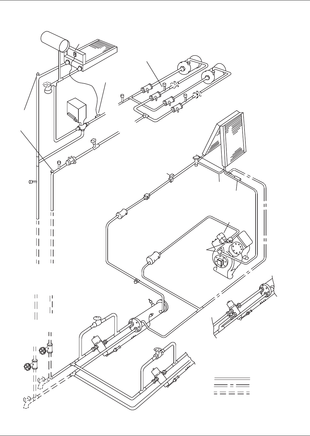
Water-Cooled, Glycol-Cooled and GLYCOOL Systems
Liebert® DS™150
4.11.9 System Piping—Piggyback Drycoolers
Figure 119 Piping schematic—Liebert DS glycol-cooled models with centrifugal piggyback drycoolers
Condenser
A
B
AB
FIELD PIPING
Drycooler
Electric
Box
Drycooler
Coil
Hose *
Bibs
Fluid
Return
To Pump
Fluid
Supply
From
Pump
A
ir Vents *
A
t Top Of
Risers
Glycol
Pumps
Flow Regulating Valve *
Expansion
Valve
Optional
Dual Pump
System Shown
Evaporator
Coil
Solenoid
Valve
Sight
Glass
Filter
Dryer
Liquid
Return
Shutoff
Valve
Shutoff
Valves *
Sensing
Bulb
External
Equalizer
Cylinder
Unloader
(Optional)
Service
Valves
Muffler Compressor
Glycol
Coolant
Circuit
One Required
Per Unit
Bypass
Valve
Bypass
Valve
Relief
Valve
Fluid
Return
From
Unit
Fluid
Supply
To Unit
2-Way Glycol
Regulating
Valve
2-Way Glycol
Regulating
Valve
To Second
Refrigeration
Circuit
Optional
3-Way Glycol
Regulating Valve
Expansion Tank
Aquastat
Sensing
Bulb
Valve
Actuator
Pressure
Tap
Pressure
Tap
Pressure
Tap
Pressure
Tap
Pressure
Tap
Unions
Unions
Hose
Bib *
Ball Valves
Check Valves On Dual
Pump Systems Only
Flow Switch Supplied
With Dual Pump Systems
Installed in Field
3-Way Chilled
Glycol Valve
DPN000706
REV 0
* Components are not supplied by Liebert
but are recommended for proper
circuit operation and maintenance
SINGLE REFRIGERATION CIRCUIT SHOWN
FACTORY PIPING
OPTIONAL PIPING
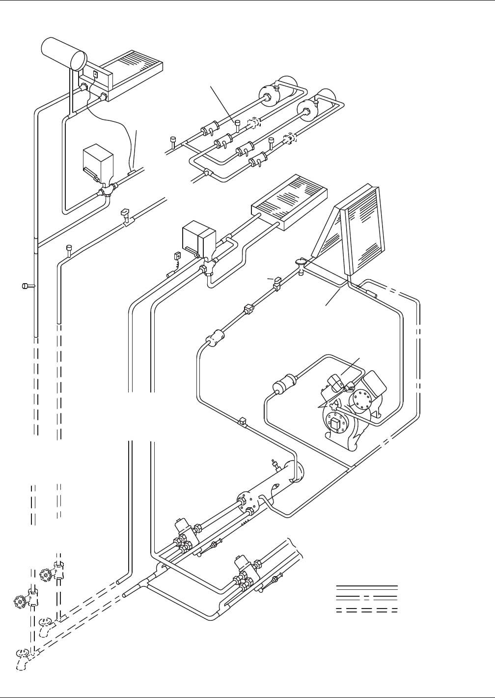
Water-Cooled, Glycol-Cooled and GLYCOOL Systems
151 Liebert® DS™
Figure 120 Piping schematic—Liebert DS GLYCOOL models with centrifugal piggyback drycoolers
r
A
B
AB
FIELD PIPING
Drycooler
Electric
Box
Drycooler
Coil
Hose *
Bibs
Fluid
Return
To Pump
Fluid
Supply
From
Pump
Glycol
Pumps
Expansion
Valve
Optional
Dual Pump
System Shown
Evaporator
Coil
Solenoid
Valve
Sight
Glass
Filter
Dryer
Liquid
Return
Shutoff
Valve
Shutoff
Valves *
Sensing
Bulb
External
Equalizer
Cylinder
Unloader
(Optional)
Service
Valves
Muffler
Compressor
Condenser
Glycol
Coolant
Circuit
One Required
Per Unit
Relief
Valve
Fluid
Return
From
Unit
Fluid
Supply
To Unit
3-Way Glycol
Regulating
Valve
3-Way Glycol
Regulating
Valve
To Second
Refrigeration
Circuit
Expansion Tank
Aquastat
Sensing
Bulb
Valve
Actuator
Valve
Actuator
Pressure
Tap
Pressure
Tap
Pressure
Tap
Pressure
Tap
Pressure
Tap
Unions
Ball Valves
Check Valves On Dual
Pump Systems Only
Flow Switch
Supplied w/
Dual Pump
Systems
3-Way
Chilled
Glycol
Valve
DPN000707
REV 0
* Components are not supplied by Liebert
but are recommended for proper
circuit operation and maintenance
SINGLE REFRIGERATION CIRCUIT SHOWN
FACTORY PIPING
OPTIONAL PIPING
Econ-O-Coil
Circuit
One Supplied
Per Unit
Econ-O-Coil
3-Way Chilled
Glycol Valve
Econ-O-Cycle
Comparator
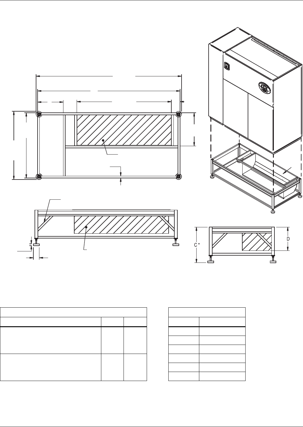
Water-Cooled, Glycol-Cooled and GLYCOOL Systems
Liebert® DS™152
4.12 ANCILLARY ITEMS—WATER-COOLED SYSTEMS
Figure 121 Floor stand dimensions—28-42kW (8-12 ton), downflow
Table 120 Floor stand and floor planning dimensions—28-42kW (8-12 ton), downflow
Dimensional Data, in. (mm) Height, in. (mm)
Model A B C* D turning vane
Air-Cooled Semi-Hermetic Models and
All Water/Glycol/GLYCOOL Models
85
(2159)
26
(660)
9 (229) 4 (111)
12 (305) 7 (187)
15 (381) 10 (264)
Air-Cooled Scroll Models and
Air-Cooled Digital Scroll Models
72
(1829)
13
(330)
18 (457) 13 (340)
21 (533) 16 (416)
24 (610) 19 (492)
Source: DPN000820, Rev. 3
DPN000820
Rev. 3
NOTE: Right side of paneled unit is flush with right side of floorstand. All other paneled sides overhang
floor stand 1" (25mm).
* Leveling feet are provided with ± 1-1/2" (38mm) adjustment from nominal height C.
Gussets supplied on floor stands
12" (305 mm) tall and greater
Turning vane air outlet
Optional turning vane can be field-installed
in supply air discharge opening for front or
rear air discharge.
Supply air
discharge
opening
Optional turning vane
shown as front air discharge.
Supply air
discharge opening
33"
(838mm)
47-15/16"
(1218mm)
34-1/2"
(876mm)
(with feet)
A+1-1/2"
(38mm) (with feet)
16-3/4"
(425mm)
1"
(25mm) TYP.
3"
(76mm)
7/8"
(23mm)
4-1/2"
(114mm)
A
B
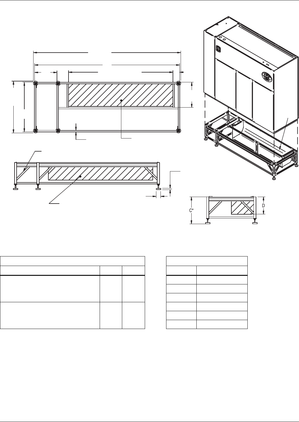
Water-Cooled, Glycol-Cooled and GLYCOOL Systems
153 Liebert® DS™
Figure 122 Floor stand dimensions—53-77kW (15-22 ton), downflow
Table 121 Floor stand and floor planning dimensions—53-77kW (15-22 ton), downflow
Dimensions, in. (mm) Height, in. (mm)
Model A B C* D - Turning Vane
Air-Cooled Semi-Hermetic Models and
All Water/Glycol/GLYCOOL Models
108
(2743)
26
(660)
9 (229) 4 (111)
12 (305) 7 (187)
15 (381) 10 (264)
Air-Cooled Scroll Models and
Air-Cooled Digital Scroll Models
97
(2464)
15
(381)
18 (457) 13 (340)
21 (533) 16 (416)
24 (610) 19 (492)
Source: DPN000930, Rev. 2
DPN000930
Rev. 2
NOTE: Right side of paneled unit is flush with right side of floor stand. All other paneled sides overhang
floor stand 1" (25mm). * Leveling feet are provided with ± 1-1/2" (38mm) adjustment from nominal height C.
Gussets supplied on floor stands
12" (305 mm) tall and greater
Turning vane air outlet
Optional turning vane can be field-installed
in supply air discharge opening for front or
rear air discharge.
Supply air
discharge
opening
Optional turning vane
shown as front air discharge.
Supply air
discharge opening
34-1/2"
(876mm)
(with feet)
A+1-1/2"
(38mm) (with feet)
33"
(838mm)
69-3/4" (1772mm)
16-3/4"
(425mm)
1"
(25mm) TYP.
3"
(76mm)
7/8"
(23mm)
A
B
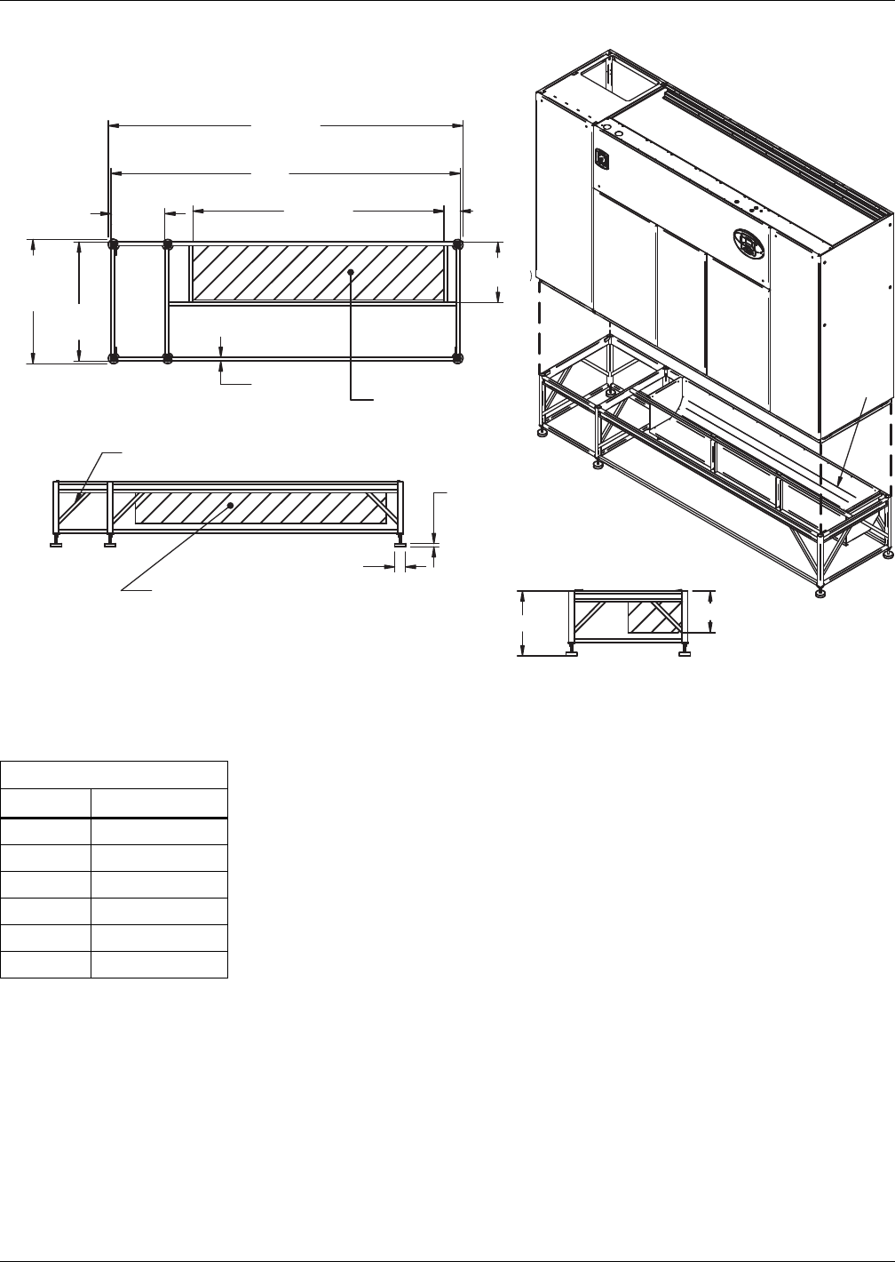
Water-Cooled, Glycol-Cooled and GLYCOOL Systems
Liebert® DS™154
Figure 123 Floor stand dimensions—105kW (30 ton), downflow
Table 122 Floor stand and floor planning dimensions—105kW (30 ton), downflow
Height, in. (mm)
C* D turning vane
9 (229) 4 (111)
12 (305) 7 (187)
15 (381) 10 (264)
18 (457) 13 (340)
21 (533) 16 (416)
24 (610) 19 (492)
Source: DPN001059, Rev. 2
D
DPN001059
Rev. 2
NOTE: Right side of paneled unit is flush with right side of floorstand. All other paneled sides overhang
floor stand 1" (25mm).
* Leveling feet are provided with ± 1-1/2" (38mm) adjustment from nominal height C.
Gussets supplied on floor stands
12" (305 mm) tall and greater
Turning vane air outlet
Optional turning vane can be field-installed
in supply air discharge opening for front or
rear air discharge.
Supply air
discharge
opening
Optional turning vane
shown as front air discharge.
Supply air
discharge opening
33"
(838mm)
34-1/2"
(876mm)
(with feet)
132-1/2"
(3366mm) (with feet)
26"
(660mm)
91-3/4"
(2330mm)
131"
(3327mm)
16-3/4"
(425mm)
1"
(25mm) TYP.
3"
(76mm)
7/8"
(23mm)
4-1/2"
(114mm)
C*
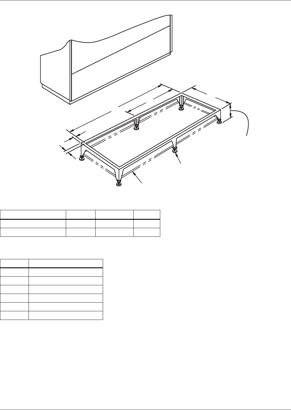
Water-Cooled, Glycol-Cooled and GLYCOOL Systems
155 Liebert® DS™
Figure 124 Floor stand dimensions, piggyback drycoolers with centrifugal fans
Table 123 Floor stand dimensions, in. (mm)
Model ABC
PD-102, PD-133, PD-150 72 (1829) 36 (914) 31 (787)
PD-223, PD-290 PD-333 97 (2464) 48-1/2 (1232) 33 (838)
Source: DPN000727, Rev. 0
Table 124 Floor stand height selection, in. (mm)
Nominal Range (Nominal ±1-1/2 *)
9 (229) 7-1/2 to 10-1/2 (191 to 267)
12 (305) 10-1/2 to 13-1/2 (267 to 343)
15 (381) 13-1/2 to 16-1/2 (343 to 419)
18 (458) 16-1/2 to 19-1/2 (419 to 495)
21 (553) 19-1/2 to 22-1/2 (495 to 572)
24 (610) 22-1/2 to 25-1/2 (572 to 648)
Leveling feet are provided with ±1-1/2" (38mm)
Adjustment from nominal height “H”.
Source: DPN000727, Rev. 0
A
BC
1"
(25.4mm)
Center Leg Provided
on 99" Cabinets
Leg Support on Models
18, 21 & 24" High
* H ± 1-1/2" (38mm)
For height selection
refer to chart.
DPN000727
Rev. 0
See Table 124 for
height selection

Water-Cooled, Glycol-Cooled and GLYCOOL Systems
Liebert® DS™156
Figure 125 Plenum dimension—28-105kW (8-30 ton), upflow
Table 125 Plenum dimensions, in. (mm)—28-105kW (8-30 ton), upflow
Dimensions, in. (mm)
Grille Size, in (mm) -
Nominal
Height
in. (mm)
Model A B
Front/Rear
Grilles Side Grille H
28-42kW (8-12 ton) Air-Cooled Scroll and
Air-Cooled Digital Scroll Models
59-1/4
(1505)
13-3/4
(349)
18 x 55
(457 x 1397)
18 x 20
(457 x 508) 20 (508)
28-42kW (8-12 ton) Semi-Hermetic and
all Water/Glycol/GLYCOOL Models
59-1/4
(1505)
26-3/4
(679)
18 x 55
(457 x 1397)
18 x 20
(457 x 508) 24 (610)
53-77kW (15-22 ton) Air-Cooled Scroll and
Air-Cooled Digital Scroll Models
82-1/4
(2089)
15-3/4
(400)
18 x 78
(457 x 1981)
18 x 20
(457 x 508) 30 (762)
53-77kW (15-22 ton) Semi-Hermetic and
all Water/Glycol/GLYCOOL Models
82-1/4
(2089)
26-3/4
(679)
18 x 78
(457 x 1981)
18 x 20
(457 x 508) 36 (914)
105kW (30 ton)—All Models 105-1/4
(2673)
26-3/4
(679)
(1) 18 x 20
(457 x 508)
(1) 18 x 78
(457 x 1981)
18 x 20
(457 x 508)
Source: DPN001187, Rev. 1
WITH GRILLE
B A
H
WITHOUT GRILLE
FRONT VIEWS
WITH GRILLE
WITHOUT GRILLE
REAR VIEWS
Panel removable
for condenser clean
out access
(Water/Glycol/GLYCOOL
models only)
RIGHT SIDE VIEWS -
CHECK ONE (1):
WITH GRILLE
WITHOUT
GRILLE
FRONT VIEW - UNIT WITH PLENUM
SIDE VIEW - UNIT WITH PLENUM
WITH GRILLE
WITHOUT
GRILLE
Notes:
1. Typical 53-77kW (15-22 Tons) unit orientation shown with grille Plenum.
View varies by unit size and Plenum selection.
2. All Plenums are shipped flat and must be field assembled.
3. Optional grille Plenum kits must include front or rear grille.
4. Non-grille Plenums are open on the top and not designed with duct flange.
LEFT SIDE VIEWS -
CHECK ONE (1):
34"
(864mm)
1"
(25mm)
76"
(1930mm)
DPN001187
Rev. 1

Guide Specifications
157 Liebert® DS™
5.0 GUIDE SPECIFICATIONS
1.0 GENERAL
1.1 SUMMARY
These specifications describe requirements for a Data Center Cooling system. The system shall be
designed to control temperature and humidity conditions in rooms containing computers or electronic
equipment, with good insulation and vapor barrier.
1.2 DESIGN REQUIREMENTS
The cooling system shall be a Liebert self-contained, factory-assembled unit with downflow or upflow
air delivery. The system shall have a net total cooling capacity of ____ kW (BTUH) with a net sensible
cooling capacity of ____ kW (BTUH) based on an entering air temperature of ____ °F (°C) dry bulb and
____ °F (°C) wet bulb, based on ASHRAE127 rating method and test method. Net capacities shall
include losses due to fan motor heat. The unit is to be supplied with ____ volt ____ ph ____ Hz
electrical service.
The indoor cooling unit shall have a short circuit current rating (SCCR) of 65,000A RMS symmetrical,
determined in accordance with the U.S. National Electric Code Section 409, Standard 508a SB, based
on test data performed at certified third-party laboratories.
1.3 SUBMITTALS
Submittals shall be provided after the agreement of the proposal and shall include: Single-Line
Diagrams; Dimensional, Electrical and Capacity Data; and Piping and Electrical Connection
Drawings.
2.0 PRODUCT
2.1 FRAME
The modular constructed frame shall be welded, formed sheet metal. It shall be protected against
corrosion using the autophoretic coating process. The frame shall be capable of being separated into
three parts in the field to accommodate rigging through small spaces.
2.1.1 Downflow Air Supply, Bottom Supply, Front Throw, Centrifugal fans
The supply air shall exit from the bottom of the unit with the air thrown toward the front of the unit.
2.1.1 Downflow Air Supply, EC Fans
The supply air shall exit from the bottom of the unit, with the ability to operate the fans within the
floor stand (requires minimum 24" raised floor height), throwing the air in a horizontal direction.
2.1.1 Downflow Air Supply, Front Supply (or Rear Supply), EC Fans
The supply air shall exit from the front of the unit utilizing direct drive EC fans.
2.1.1 Downflow Air Return
The return air shall enter the unit from the top.
2.1.1 Upflow Top Air Supply, Front Throw
The supply air shall exit from the top of the cabinet with the air throw towards the front.
2.1.1 Upflow Top Air Supply, Rear Throw
The supply air shall exit from the top of the cabinet with the air throw towards the back.
2.1.1 Upflow Air Return, Front
The return air shall enter the unit from the front of the cabinet through factory installed grilles.
Grilles shall be painted black.
2.1.1 Upflow Air Return, Rear
The return air shall enter the unit from the back of the cabinet.

Guide Specifications
Liebert® DS™158
2.1.2 Exterior Panels
The exterior panels shall be insulated with a minimum 1 in. (25mm), 1.5 lb. (0.68 kg) density fiber
insulation. The main front panel shall have captive 1/4 turn fasteners. The main unit color shall be
______.
2.1.2.1 Double-Skin Panels (Optional)
The exterior panels shall be internally lined with 20 gauge sheetmetal, sandwiching the insulation
between the panels, for easy cleaning.
2.2 FILTERS—DOWNFLOW UNIT
The filter chamber shall be located within the cabinet, and filters shall be removable from the top of
the unit.
2.2.1 Filters, 4"
Filters shall be deep pleated 4" filters with an ASHRAE 52.2 MERV8 rating (45% ASHRAE 52.1) or
ASHRAE 52.2 MERV11 rating (60-65% ASHRAE 52.1).
2.2.1 Filters, 2" Pre-Filter With 2" Filter
Filters shall be 2" ASHRAE 52.2 MERV8 (40% ASHRAE 52.1) pre-filter, with 2" ASHRAE 52.2
MERV11 (60-65% ASHRAE 52.1) efficiency filter.
2.2.2 Extra Filter Set
____ extra set(s) of filters shall be provided per system.
2.3 FAN SECTION
2.3.1 Centrifugal Blower Section
The blower section shall be designed for ___ CFM (CMH) at an external static pressure of ___ in. wg.
(Pa). The fans shall be the centrifugal type, double width double inlet and shall be dynamically
balanced as a completed assembly. The shaft shall be heavy duty steel with self-aligning,
permanently sealed, pillow block bearings with a minimum L3 life of 200,000 hours. The fans shall
draw air through the A-frame coil to ensure even air distribution and maximum coil performance. A
static regain duct shall be factory-installed to the bottom of the blower on downflow units.
2.3.1.1 Motor
The fan motor shall be ____ hp (kW) at 1750 rpm @60hz (1450 rpm @50hz), mounted to an automatic,
spring tensioning base. The motor shall be removable from the front of the cabinet.
2.3.1.1.1 Premium Efficiency Motor
The fan motor shall be Open Drip-Proof, Premium efficiency and shall meet NEMA Premium
standard. Motor efficiency shall be ____%.
2.3.1.1.1 TEFC Motor (Optional)
The motor shall be Totally Enclosed Fan Cooled for protection in harsh environments.
2.3.1.2 Drive Package
The motor sheave and fan pulley shall be double-width, fixed-pitch. Two belts, sized for 200% of the
fan motor horsepower shall be provided with the drive package. An auto-tension system shall provide
constant tension on the belts. Belts, shaft, blower bearings, sheave and pulley shall be warranted for
five years (parts only).

Guide Specifications
159 Liebert® DS™
2.3.1 Electronically Commutated (EC) Fan, Direct-Drive, Variable Speed
The fans shall be plug/plenum type, single inlet and shall be dynamically balanced, and the drive
package shall be direct drive, electronically commutated and variable speed. The fans shall be located
to draw air over the A-frame coil to ensure even air distribution and maximum coil performance. EC
fans shall be available on Downflow models only, and fans may be field- lowered into a raised floor
with minimum height of 24" in order to achieve more efficient fan operation. EC fans may operate
within the Liebert DS cabinet, instead of underfloor.
DS053, DS070, DS077 fan motor(s) shall be nominal 4.15 hp each with a maximum operating speed of
1510 rpm; quantity, two. DS105 fan motor(s) shall be nominal 3.62 hp each, with a maximum
operating speed of 2150 rpm; quantity, three.
2.4 HUMIDIFIER
A humidifier shall be factory-installed inside the unit. Bypass air slots shall be included to enable
moisture to be absorbed into the air stream. The humidifier capacity shall be ____lb./hr (kg/hr). The
humidifier shall be removable from the front of the cabinet.
2.4.1 Infrared Humidifier
The humidifier shall be of the infrared type consisting of high intensity quartz lamps mounted above
and out of the water supply. The humidifier pan shall be stainless steel and arranged to be removable
without disconnecting high voltage electrical connections. The complete humidifier section shall be
pre-piped, ready for field connection to water supply. The humidifier shall be equipped with an
automatic water supply system and shall have an adjustable water-overfeed to prevent mineral
precipitation. A high-water detector shall shut down the humidifier to prevent overflowing. A
factory-provided air-gap shall prevent backflow of the humidifier supply water.
2.4.1 Steam Generating Canister Humidifier
A canister-type steam canister shall be factory-installed in the cooling unit and shall be controlled by
the microprocessor control system. It shall be complete with disposable canister, all supply and drain
valves, steam distributor and electronic controls. The need to change canister shall be indicated on
the microprocessor control panel. The humidifier shall be designed to operate with water conductivity
from 200-500 micromhos. An air-gap within the humidifier assembly shall prevent backflow of the
humidifier supply water. Not available with EC fans or on upflow configurations.
2.5 REHEAT
The indoor cooling unit shall include a factory-installed reheat to control temperature during
dehumidification.
2.5.1 Three-Stage Electric Reheat
The electric reheat coils shall be low watt density, 304/304 stainless steel fin tubular construction,
protected by thermal safety switches, shall be ____ kW (____ BTUH) controlled in three stages. The
reheat elements shall be removable from the front of the cabinet.
2.5.1 SCR Electric Reheat
The electric reheat coils shall be low watt density, 304/304 stainless steel fin tubular construction,
protected by thermal safety switches, ____ kW (____ BTUH) controlled by multiple pulses to achieve
tight temperature control. The reheat elements shall be removable from the front of the cabinet.
Available on indoor units with standard Scroll compressors, only.
2.6 DUAL REFRIGERATION SYSTEM
Each unit shall include two (2) independent refrigeration circuits and shall include hot gas mufflers
(semi-hermetic compressors units only), liquid line filter driers, refrigerant sight glass with moisture
indicator, externally equalized expansion valves and liquid line solenoid valves. Compressors shall be
located outside the airstream and shall be removable and serviceable from the front of the unit.

Guide Specifications
Liebert® DS™160
2.6.1 Semi-Hermetic Compressor With Four-Step Unloaders Control
The compressor shall be semi-hermetic with a suction gas cooled motor, vibration isolators, thermal
overloads, oil sight glass, automatic reset high pressure switch with control lockout after three
failures, low pressure transducer, suction line strainer, crankcase heaters, service valves, reversible
oil pumps for forced feed lubrication, a maximum operating speed of 1750 rpm. The system shall
include cylinder unloaders on the semi-hermetic compressors. The unloaders shall be activated by
solenoid valves which are controlled from the microprocessor control. In response to the return air
temperature, the microprocessor control shall activate the unloader solenoids and the liquid line
solenoids such that four stages of refrigeration cooling are obtained. The stages shall be: 1) one
compressor, partially loaded, 2) two compressors partially loaded, 3) one compressor partially loaded,
one compressor fully loaded, 4) two compressors fully loaded. On a call for dehumidification, the
microprocessor control shall insure that at least one compressor is on full for proper humidity control.
Hot Gas bypass shall not be an acceptable means of capacity control due to increased energy
consumption.
2.6.1 Scroll Compressors
The compressor shall be scroll-type with a variable capacity operation capability. Compressor
solenoid valve shall unload the compressor and allow for variable capacity operation. The compressor
shall be suction gas cooled motor, vibration isolators, thermal overloads, automatic reset high
pressure switch with lockout after three failures, rotalock service valves, crankcase heaters, low
pressure transducer, suction line strainer, and a maximum operating speed of 3500 rpm. Hot gas
bypass shall not be an acceptable means of capacity control, due to increased energy consumption.
2.6.1 Digital Scroll Compressors
The compressor shall be variable capacity, scroll-type, capable of operating between 20% and 100%
compressor capacity. The compressor shall be suction gas cooled motor, vibration isolators, thermal
overloads, automatic reset high pressure switch with lockout after three failures, rotalock service
valves, crankcase heaters, low pressure transducer, suction line strainer and a maximum operating
speed of 3500 rpm. Hot gas bypass shall not be acceptable means of capacity control, due to increased
energy consumption.
2.6.2 Evaporator Coil, DX Coil
The evaporator coil shall be A-frame design with offset orientation and have ____sq. ft. (m2) face area,
three rows deep. It shall be constructed of rifled copper tubes and aluminum fins and have a
maximum face velocity of ____ ft. per minute (m/s) at ____ CFM (CMH). A stainless steel condensate
drain pan shall be provided.
2.6.2.1 Polymeric Coating (Optional)
The coil shall be coated with a high performance polymeric coating process to provide corrosion
resistance within 2 to 12 pH range.
2.6.3 R-407C Refrigerant, non-HCFC
The system shall be designed for use with R-407C refrigerant, which meets the EPA clean air act for
phase-out of HCFC refrigerants.

Guide Specifications
161 Liebert® DS™
2.7 LIEBERT iCOM™ MICROPROCESSOR CONTROL WITH SMALL GRAPHIC DISPLAY
The Liebert iCOM unit control shall be factory-set for Intelligent Control, which uses “fuzzy logic” and
“predictive” methods. Proportional and Tunable PID shall also be user-selectable options. Internal
unit component control shall include the following:
Compressor Short Cycle Control—Prevents compressor short-cycling and needless compressor
wear.
System Auto Restart—The auto restart feature shall automatically restart the system after a
power failure. Time delay is programmable.
Sequential Load Activation—On initial startup or restart after power failure, each operational
load is sequenced with a minimum of one second delay to minimize total inrush current.
Econ-O-Coil Flush Cycles—Econ-O-Coils are periodically flushed to prevent a buildup of
contaminants.
Predictive Humidity Control—Calculates the moisture content in the room and prevents
unnecessary humidification and dehumidification cycles by responding to changes in dew point
temperature.
The Liebert iCOM control shall be compatible with all Liebert remote monitoring and control devices.
Options are available for BMS interface via Modbus, BACnet and SNMP.
The Liebert iCOM control processor shall be microprocessor based with a 128x64 dot matrix graphic
front monitor display and control keys for user inputs mounted in an ergonomic, aesthetically
pleasing housing. The display and housing shall be viewable while the unit panels are open or closed.
The controls shall be menu driven. The display shall be organized into three main sections: User
Menus, Service Menus and Advanced Menus. The system shall display user menus for active alarms,
event log, graphic data, unit view/status overview (including the monitoring of room conditions,
operational status in % of each function, date and time), total run hours, various sensors, display
setup and service contacts. A password shall be required to make system changes within the service
menus. Service menus shall include setpoints, standby settings (lead/lag), timers/sleep mode, alarm
setup, sensor calibration, maintenance/wellness settings, options setup, system/network setup,
auxiliary boards and diagnostics/service mode. A password shall be required to access the advanced
menus, which include the factory settings and password menus.
The User Menus Shall be Defined as Follows:
Active Alarms: Unit memory shall hold the 200 most recent alarms with time and date stamp for
each alarm.
Event Log: Unit memory shall hold the 400 most recent events with ID number, time and date
stamp for each event.
Graphic Data View: Eight graphic records shall be available: return air temperature, return air
humidity, supply air temperature, outdoor temperature and four custom graphs.
Unit View - Status Overview: Simple or Graphical “Unit View” summary displays shall include
temperature and humidity values, active functions (and percent of operation) and any alarms of the
host unit.
Total Run Hours: Menu shall display accumulative component operating hours for major
components including compressors, Econ-O-Coil (FC), fan motor, humidifier and reheat.
Various Sensors: Menu shall allow setup and display of optional custom sensors. The control shall
include four customer accessible analog inputs for sensors provided by others. The analog inputs shall
accept a 4 to 20 mA signal. The user shall be able to change the input to 0 to 5VDC or 0 to 10VDC if
desired. The gains for each analog input shall be programmable from the front display. The analog
inputs shall be able to be monitored from the front display.
Display Setup: Customer shall pre-select the desired grouping of display languages at the time of
the order from the following choices:
Group 1: English, French, Italian, Spanish, German
Group 2: English, Russian, Greek
Group 3: English, Japanese, Chinese, Arabic
Service Contacts: Menu shall allow display of local service contact name and phone number.

Guide Specifications
Liebert® DS™162
The Service Menus Shall be Defined as Follows:
Setpoints: Menu shall allow setpoints within the following ranges:
• Temperature Setpoint: 65-85ºF (18-29ºC)*
• Temperature Sensitivity: +1-10ºF (0.6-5.6ºC)
• Humidity Setpoint: 20-80% RH*
• Humidity Sensitivity: 1-30% RH
• High Temperature Alarm: 35-90ºF (2-32ºC)
• Low Temperature Alarm: 35-90ºF (2-32ºC)
• High Humidity Alarm: 15-85% RH
• Low Humidity Alarm: 15-85% RH
* The microprocessor may be set within these ranges, however, the unit may not be able to control
to extreme combinations of temperature and humidity.
Standby Settings/Lead-Lag: Menu shall allow planned rotation or emergency rotation of operating
and standby units.
Timers/Sleep Mode: Menu shall allow various customer settings for turning On/Off unit.
Alarm Setup: Menu shall allow customer settings for alarm notification (audible/local/remote). The
following alarms shall be available:
• High Temperature
• Low Temperature
• High Humidity
• Low Humidity
• Compressor Overload (Optional)
• Main Fan Overload (Optional)
• Humidifier Problem
• High Head Pressure
• Change Filter
•Fan Failure
• Low Suction Pressure
•Unit Off
Audible Alarm: The audible alarm shall annunciate any alarm that is enabled by the operator.
Common Alarm: A programmable common alarm shall be provided to interface user-selected alarms
with a remote alarm device.
Remote Monitoring: All alarms shall be communicated to the Liebert monitoring system with the
following information: date and time of occurrence, unit number and present temperature and
humidity.
Sensor Calibration: Menu shall allow unit sensors to be calibrated with external sensors.
Maintenance/Wellness Settings: Menu shall allow reporting of potential component problems
before they occur.
Options Setup: Menu shall provide operation settings for the installed components.
System/Network Setup: Menu shall allow Unit-to-Unit (U2U) communication and setup for
Teamwork modes of operation (up to 32 units).
Teamwork Modes of Operation: Saves energy by preventing operation of units in opposite modes
multiple units.
Auxiliary Boards: Menu shall allow setup of optional expansion boards.
Diagnostics/Service Mode: The Liebert iCOM control shall be provided with self-diagnostics to aid
in troubleshooting. The microcontroller board shall be diagnosed and reported as pass/not pass.
Control inputs shall be indicated as on or off at the front display. Control outputs shall be able to be
turned on or off from the front display without using jumpers or a service terminal. An LED on a
circuit board will indicate each control output.
The Advanced Menus Shall be Defined as Follows:
Factory Settings: Configuration settings shall be factory-set based on the pre-defined component
operation.
Change Passwords: Menu shall allow new passwords to be set or changed.

Guide Specifications
163 Liebert® DS™
2.7 LIEBERT iCOM™ MICROPROCESSOR CONTROL WITH LARGE GRAPHIC
DISPLAY (OPTIONAL)
The Liebert iCOM unit control with large graphic display shall include all of the features as the
Liebert iCOM with small graphic display, except that it includes a larger graphical display and shall
include the additional features of: System View, Spare Parts List, Unit Diary.
The Liebert iCOM control processor shall be microprocessor based with a 320x240 dot matrix graphic
front monitor display panel and control keys for user inputs mounted in an ergonomic, aesthetically
pleasing housing.
System View - Status Overview: System View shall display a summary of operation for the total
number of operating units within a Unit-to-Unit (U2U) configuration.
Spare Parts List: Menu shall include a list of critical spare parts, their quantity and part numbers.
Unit Diary: Menu shall include a free field area within the unit memory where unit history may be
stored for reference.
2.7 LIEBERT iCOM WALL MOUNT LARGE GRAPHIC DISPLAY vNSA PANEL
(OPTIONAL)
The Liebert iCOM Large Graphic Display Kit shall include an ergonomic, aesthetically pleasing
housing, a 320x240 dot matrix graphic display and a 120V power supply. The Wall Mount Large
Graphic Display shall be used to allow remote location of a System View display and all features of
the Large Graphic User, Service and Advanced menus for use with Liebert iCOM controlled products
connected for Unit-to-Unit (U2U) communications. This panel is also used to network together so they
can be place in 1 of the 3 team work modes and lead/lag standby rotation as well as cascade mode.
2.8 DUAL-COOLING CHILLED WATER COIL
The dual-cooling source system shall consist of an air- or water-cooled compressorized (DX) system
with the addition of a chilled water coil, a modulating control valve and a comparative temperature
sensor. The system shall be able to function either as a modulating chilled water system or as a
compressorized (DX) system, or a combination of both. The primary cooling mode shall be chilled
water, if available. Switchover between the two cooling modes shall be performed automatically by
the microprocessor control.
Four (4) pipes shall be included on water/glycol systems: chilled water supply, chilled water water
return, condenser water supply and condenser water return.
Four pipes shall be included on air-cooled systems: chilled water supply, chilled water return, hot gas
refrigerant line, liquid refrigerant line.
2.8.1 Dual-Cooling Source Control Valve
The chilled water circuit shall include a three-way modulating valve. The microprocessor shall
position the valve in response to room conditions. Cooling capacity will be controlled by bypassing
chilled water around the coil. The modulating valve travel for dehumidification shall be proportional.
2.8.1 CuNi Coil Chilled Water Coil (Optional)
A 70/30 CuNi chilled water shall be provided for Dual-Cooling units that are applied to a cooling
tower loop or other open water system. This option is required on open cooling tower applications, and
constant chilled water flow must be provided in order to periodically circulate chilled water through
the coil when idle.
2.8.1.1 Polymeric Coating on Liebert Econ-O-Coil™ and DX Coil (Optional)
The coil shall be coated with a high performance polymeric coating process to provide corrosion
resistance on the exterior of the coil, within 2 to 12 pH range.
2.9 MISCELLANEOUS OPTIONS
2.9.1 Non-Locking Disconnect Switch (Optional)
The manual disconnect switch shall be mounted in the high- voltage section of the electrical panel.
The switch shall be accessible with the door closed.

Guide Specifications
Liebert® DS™164
2.9.1 Locking Disconnect Switch (Optional)
The manual disconnect switch shall be mounted in the high voltage section of the electrical panel. The
switch shall be accessible from the outside of the unit with the door closed and prevent access to the
high voltage electrical components until switched to the “OFF” position.
2.9.2 High-Temperature Sensor (Optional)
The high-temperature sensor shall be factory-installed in the unit and shall be factory-set to 125ºF
(52ºC). It shall immediately shut down the environmental control system when activated. The sensor
shall be mounted with the sensing element in the return air.
2.9.3 Smoke Sensor (Optional)
The smoke sensor shall immediately shut down the environmental control system and activate the
alarm system when activated. The smoke sensor shall be mounted in the electrical panel with the
sensing element in the return air compartment. The smoke sensor is not intended to function as or
replace any room smoke detection system that may be required by local or national codes. The smoke
sensor shall include a supervision contact closure.
2.9.4 Condensate Pump, Dual Float (Optional)
The condensate pump shall have a minimum capacity of 145 GPH (548 l/h) at 20 ft. (58 kPa) head. It
shall be complete with integral dual-float switches, pump-and-motor assembly and reservoir. The
secondary float shall send a signal to the local alarm and shut down the unit upon high water
condition.
2.9.5 Low-Voltage Terminal Package (Optional)
Factory-installed and wired terminals shall be provided for customer connection to lock out the reheat
and humidifier upon contact closure. Two extra N/O common alarm contacts shall be provided. Two
extra remote shutdown terminals shall be provided.
2.9.6 Remote Humidifier Contact (Optional)
A pair of N/O contacts shall be provided for connection to a remote humidifier.
2.9.7 Main Fan Overload (Optional)
A pair of N/O contacts shall be factory-installed and wired to indicate Main Fan Overload.
2.9.8 Compressor Overload (Optional)
A pair of N/O contacts shall be factory-installed and wired to each compressor to indicate Compressor
Overload.
2.10 AIR-COOLED SYSTEMS
The indoor evaporator unit shall include refrigerant piping, with a factory holding charge of nitrogen.
The hot-gas and liquid lines shall be spun shut and shall include a factory-installed Schrader valve.
Field-relief of the Schrader valve shall indicate a leak-free system. Air-cooled systems shall be field-
piped and wired to a condenser, using field-supplied refrigerant piping and wiring. The system shall
be field-charged with refrigerant, supplied by others.
2.10.1 Standard Features—Air-Cooled Microchannel Condenser Design
Condenser shall consist of microchannel condenser coil(s), propeller fan(s) direct-driven by individual
fan motor(s), electrical controls, housing and mounting legs. The Liebert air-cooled condenser shall
provide positive refrigerant head pressure control to the Precision Cooling indoor unit by adjusting
heat rejection capacity. Microchannel coils shall provide superior heat transfer, reduce air-side
pressure drop, increase energy efficiency and significantly reduce the system refrigerant volume
required. EC fans and fan operating techniques shall provide reduced maximum sound levels.
Various methods shall be available to match indoor unit type, maximum outdoor design ambient and
maximum sound requirements.

Guide Specifications
165 Liebert® DS™
2.10.1.1 Aluminum Microchannel Coil
Liebert microchannel coils shall be constructed of aluminum microchannel tubes, fins and manifolds.
Tubes shall be flat and contain multiple, parallel flow microchannels and span between aluminum
headers. Full-depth louvered aluminum fins shall fill spaces between the tubes. Tubes, fins and
aluminum headers shall be oven brazed to form a complete refrigerant-to-air heat exchanger coil.
Copper stub pipes shall be electric resistance welded to aluminum coils and joints protected with
polyolefin to seal joints from corrosive environmental elements. Coil assemblies shall be factory leak-
tested at a minimum of 300 psig (2068kPag). Hot gas and liquid lines shall be copper and shall be
brazed using nitrogen gas flow to the stub pipes with spun closed ends for customer piping
connections. Complete coil/piping assembly shall be then filled and sealed with an inert gas holding
charge for shipment.
2.10.1.1 Aluminum Microchannel Coil with E-Coat
Aluminum microchannel coil with E-coat shall provide a flexible epoxy coating to all coil surface areas
without material bridging between fins. E-coat shall increase coil corrosion protection and shall
reduce heat rejection capacity degradation to less than 10% after a severe 2000 hour 5% neutral salt
spray test (ref. ASTM B117). The coating process shall ensure complete coil encapsulation, and the
color shall be black.
2.10.1.2 Fan Motor/Blade Assembly
The fan motor/blade assembly shall have an external rotor motor, fan blades and fan/finger guard.
Fan blades shall be constructed of cast aluminum or glass-reinforced polymeric material. Fan guards
shall be heavy gauge, close meshed steel wire, coated with a black corrosion resistant finish. Fan
terminal blocks shall be located in an IP54 enclosure located on the top of the fan motor. Fan
assemblies shall be factory-balanced, tested before shipment and mounted securely to the condenser
structure.
2.10.1.3 EC Fan Motor
The EC Fan motors shall be electronically commutated for variable speed operation and shall have
ball bearings. The EC fans shall provide internal overload protection through built-in electronics.
Each EC fan motor shall have a built-in controller and communication module, linked via RS485
communication wire to each fan and the Premium Control Board, allowing each fan to receive and
respond to precise fan speed inputs from the Premium Control Board.
2.10.1.4 Electrical Controls
Electrical controls and service connection terminals shall be provided and factory wired inside the
attached control panel section. A locking disconnect switch shall be factory-mounted and wired to the
electrical panel and controlled via an externally mounted locking and lockable door handle. Only
high-voltage supply wiring and low voltage indoor unit communication/interlock wiring are required
at condenser installation.
2.10.1.5 EC Fan Speed & Premium Control
The EC Fan/Premium Control System shall include an electronic control board, EC fan motor(s) with
internal overload protection, refrigerant and ambient temperature thermistors and refrigerant
pressure transducers. The control board shall receive an indoor unit run signal via field-supplied low
voltage interlock wires to the compressor side switch, via field-supplied CANbus communication
wires from the indoor unit's Liebert iCOM control (future feature) or via both. The control board shall
use sensor and communication inputs to maintain refrigerant pressure by controlling each EC fan on
the same refrigerant circuit to the same speed.
2.10.1.6 Cabinet
The condenser cabinet shall be constructed of bright aluminum sheet and divided into individual fan
sections by full width baffles. Internal structural support members, including coil support frame,
shall be galvanized steel for strength and corrosion resistance. Panel doors shall be provided on two
sides of each coil/fan section to permit coil cleaning. An electrical panel shall be contained inside a
factory mounted, NEMA 3R weatherproof electrical enclosure.

Guide Specifications
Liebert® DS™166
2.10.1.7 Mounting Legs
2.10.1.7.1 Standard Aluminum Legs
Aluminum legs shall be provided to mount unit for vertical air discharge with rigging holes for
hoisting the unit into position. Standard height is 18in. (457mm).
2.10.1.7.1 Optional Galvanized Steel Legs with Bracing
Condensers shall be shipped with [36in. (914mm)] [48in. (1219mm)] [60in. (1524mm)] mounting legs
with stabilization bracing. Legs, bracing and hardware shall be galvanized steel.
2.10.1 Air-Cooled Microchannel Condenser Accessories (Options)
2.10.1.1 Liebert Lee-Temp™ Receiver Kit
Liebert Lee-Temp Receiver Kit shall contain an insulated, heated receiver tank with sight glasses,
mounting plate, mounting hardware, pressure relief valve, rotalock valve for refrigerant charge
isolation and piping assembly with head pressure operated 3-way valve and check valve. Components
shall be field-assembled to the condenser. The 3-way valve shall sense refrigerant head pressure and
adjust the flooding charge in the condenser coil to adjust the condenser heat rejection capacity. The
Liebert Lee-Temp heater shall be [(150W) (300W)], shall include an integral thermostat to maintain
refrigerant temperature at a minimum of 85°F (29°C) and shall require a separate power supply of
[(208/230-1-60) (120-1-60 volt)].
The Liebert Lee-Temp Kit shall function with Liebert MC variable speed fan motors and electronic
controls that lower fan speed in lower outdoor ambient temperatures for maximum energy efficiency.
This system shall allow system startup and positive head pressure control with ambient
temperatures as low as -30°F (-34.4°C).
2.10.1.2 Fusible Plug Kit
A fusible plug kit shall be field-installed on the liquid line for compliance with building codes
requiring refrigerant relief during high temperature and building fire conditions.
2.10.1.3 IBC/OSHPD Seismic Certification and IBC Wind/Snow Load Complaint
IBC/OSHPD Seismic Certification and IBC Wind/Snow Load Compliant condensers shall be provided
with any applicable bracing and field installation instructions. Condensers shall bear a label
certifying compliance with IBC/OSHPD requirements.
2.10.1.3.1 Seismic IBC/OSHPD (Optional)
Install condenser in accordance with manufacturer's installation instructions provided with seismic
option. Firmly anchor maintaining manufacturer's recommended clearances. Mounting requirement
details such as anchor brand, type, embedment depth, edge spacing, anchor-to-anchor spacing,
concrete strength, special inspection and attachment to non-building structures must be outlined and
approved by the Engineer of Record for the projection or building. Wiring and piping connections
must permit movement in three dimensions and isolate the unit from field connections. Electrical
conduit shall be flexible having at least one bend between the rigid connection at the unit cabinet and
the connection to rigid conduit or foundation. The piping flexible connection or loop must be suitable
for the operation pressure and temperature of the system. Furnish copy of manufacturer's piping
connection diagram submittal to piping contractor.
2.10.1 Standard Features—Air-Cooled Condenser, Fin-Tube Coil Design
The Liebert-manufactured outdoor air-cooled condenser shall be the low-profile, multiple direct drive,
propeller fan type. The condenser shall balance the heat rejection of the compressor at ____ °F (°C)
ambient. The condenser shall be constructed of aluminum and contain a copper tube, aluminum fin
coil arranged for (horizontal) (vertical) air discharge.
2.10.1.1 Fan Speed Head Pressure Control
The winter control system for the air-cooled condenser shall be Liebert Fan Speed Control. The
variable speed motor shall operate from 0 to 230 volts single phase, 10 to 1050 rpm. It shall be
designed with ball bearings, permanent lubrication, internal overload protection, 40°C rise at full
speed, 65°C rise at 10 rpm. The control system shall be complete with transducers, thermostats and
electrical control circuit, factory prepackaged in the integral condenser control box. The transducer
shall automatically sense the highest head pressure of either operating compressor and control the

Guide Specifications
167 Liebert® DS™
variable speed fan on the air-cooled condenser to properly maintain the head pressure. The Liebert
Fan Speed Control system shall provide positive startup and operation in ambient temperatures as
low as -20°F (-28.9°C). The air-cooled condenser shall have a ____ volt, ____ ph ____ Hz power supply.
2.10.1.2 Liebert Lee-Temp™, Heated Receiver Head Pressure Control System
The winter control system for the air-cooled condenser shall be Liebert Lee-Temp. The Liebert
Lee-Temp system shall allow startup and positive head pressure control with ambient temperatures
as low as -30°F (-34.4°C). The Liebert Lee-Temp package shall include the following components for
each refrigeration circuit: insulated receiver, pressure relief valve, head pressure three-way control
valve and rotalock valve for isolating the refrigerant charge. The Liebert Lee-Temp receiver shall be
factory-insulated and mounted ready for the field connection to the air-cooled condenser. The Liebert
Lee-Temp heater shall require a separate power supply of ____ volt, single phase.
2.10.1 Standard Features—Liebert Quiet-Line Condenser Fin-Tube Coil Design (Optional)
Fan motors shall be 12-pole, 570 rpm, equipped with rain shields and permanently sealed ball
bearings. Motors shall include built-in overload protection. Motors shall be rigidly mounted on
die-formed galvanized steel supports. Disconnect switch shall be a standard feature.
2.10.2.1 Condenser Disconnect Switch (Optional)
A disconnect switch shall be factory-mounted and wired to the condenser control panel, accessible
from the exterior (standard on Quiet-Line models).
2.10 WATER/GLYCOL SYSTEMS
The indoor evaporator unit shall include factory installed refrigerant piping, and factory charged with
R-407C refrigerant. Water/glycol systems shall be field piped to an external heat rejection source such
as a cooling tower (by others) or drycooler with pump package.
2.10.1 Paradenser™ Cleanable Shell and Tube Condenser
The water-cooled condensers for each circuit shall be cleanable, shell-and-tube, counter flow type. The
heads shall be removable to allow for cleaning of the water tubes. Condensers shall be rated for a
maximum refrigerant pressure of 400 psi at 200°F (2758 kPa at 93.3°C). The condenser shall be
capable of operating with R-407C refrigerant. The unit shall require ____ GPM (l/m) of ____ °F (°C)
water and have a maximum pressure drop of ____ psi (kPa).
2.10.2 Water/Glycol Regulating Valve, Two-Way with Adjustable Bypass Valve
The condenser shall be pre-piped with a two-way regulating valve which is head pressure actuated. A
gate valve shall bypass the regulating valve.
2.10.2 Water/Glycol Regulating Valve, Three-Way
The condenser shall be pre-piped with a three-way regulating valve which is head pressure actuated.
2.10.2 Pressure Rating, 150 psi (1034 kPa), Scroll and Semi-Hermetic Compressors
The condenser water circuit shall be designed for a pressure of 150 psi (1034 kPa)
2.10.3 Pressure Rating, 350 psi (2413 kPa), Scroll and Semi-Hermetic Compressors
The condenser water circuit shall be designed for a pressure of 350 psi (2413 kPa)
2.10.3 Pressure Rating, 350psi (2413 kPa), Digital Scroll Models
The condenser water circuit shall be designed for a pressure of 350 psi (2413 kPa), using motorized
ball-valves to control refrigerant head pressure.

Guide Specifications
Liebert® DS™168
2.10.3 GLYCOOL Fluid Economizer Systems
In addition to the DX (refrigerant) evaporator coil, a factory piped fluid economizer coil shall enable
the system to operate in Economizer mode when the water/glycol temperature is at least 7°F lower
than the return air temperature to the indoor unit. The system shall operate in partial economization,
supplemented by DX operation and in full economization when fluid temperatures are low enough to
offset room load. The economizer control system shall be factory installed and wired, and shall
automatically control switchover between economizer mode and DX mode.
2.10.3.1 GLYCOOL™ (Economizer) Coil
The GLYCOOL Economizer coil shall be constructed of copper tubes and aluminum fins. The coil
shall be A-frame or V-frame in order to minimize air pressure drop and maximize cooling capacity,
and shall be nested with the DX coil. The Econ-O-Coil shall be upstream of the DX coil to enable pre-
cooling of the air, during partial economizer operation. A constant flow of water shall be available to
enable the system to periodically flush the economizer coil of sediments that could cause pit corrosion
if not flushed out of the coil.
The Economizer coil shall have a net Sensible Cooling Capacity of ____ BTUH (kW) with 45°F (7.2°C)
entering glycol solution temperature. The total system shall require ____ GPM (l/s) and the total unit
pressure drop shall not exceed ____ feet of water (kPa), when in the economizer mode of operation.
2.10.3.2 GLYCOOL Three-Way Control Valve
The GLYCOOL Economizer coil shall be equipped with a fully proportional 3-way control valve,
designed for a maximum operating pressure of 150psi (1034 kPa). This motorized control valve shall
control the amount of flow to the economizer coil to control room temperature and relative humidity.
2.10.3.3 High-Pressure System, 350 psi (2413 kPa) (Option)
The GLYCOOL Economizer system shall be designed for a water/glycol static pressure of 350 psi
(2413 kPa).
2.10.4.3 CuNi Economizer Coil to Inhibit Coil Corrosion
A 70/30 CuNi Econ-O-Coil shall be provided when the Econ-O-Coil is connected to a cooling tower loop
or other open water system. This option is required on open cooling tower applications in order to
inhibit internal coil corrosion, due to lack of proper water system treatment and lack of fluid
circulation through the coil.
2.11 DRYCOOLER GLYCOL FLUID COOLER
The drycooler shall be the low profile, slow speed, multiple direct drive, propeller fan type. The
drycooler shall be constructed of aluminum and contain a copper tube aluminum fin coil with an
integral electric control panel and disconnect switch. The drycooler shall be designed for ____ °F (°C)
ambient.
2.11.1 Pump Package, Glycol System
This system shall be provided with a centrifugal pump mounted in a weatherproof and vented
enclosure. The pump shall be rated for ____ GPM (l/m) at ____ ft. of head (kPa) and operate on ____
volt, 3-phase, ____ Hz.
2.11.1 Dual Pump Package, Glycol System
The dual pump package shall include pumps, enclosure, field-mounted flow switch and a separate
factory-wired control box (including a lead/lag switch for the pumps). The standby pump shall
automatically start upon failure of the lead pump. Each pump shall be rated for ____ GPM (l/s) at ____
feet of head (kPa).

Guide Specifications
169 Liebert® DS™
2.12 LIEBERT LIQUI-TECT® SENSORS
Provide ____ (quantity) solid-state water sensors under the raised floor.
2.13 FLOOR STAND
The floor stand shall be constructed of a welded steel frame. The floor stand shall have adjustable legs
with vibration isolation pads. The floor stand shall be ____ in. (mm) high.
2.13.1 Seismic Rated Floor Stand (Optional)
The floor stand shall be seismic rated and shall be field-attached to the unit frame, and to the floor.
2.13.2 Floor Stand Turning Vane (Optional)
A turning vane shall be supplied with the floor stand and shall be designed for the specified floor
stand height.
2.14 RETURN AIR PLENUM FOR DOWNFLOW UNITS
The air plenum shall be constructed of 20 gauge steel, powder coated to match unit color. The plenum
shall be ___" high. A door shall be included in the front of the plenum to enable front filter access. Air
shall enter the plenum from the top.
2.14 DISCHARGE AIR PLENUM FOR UPFLOW UNITS, WITH DISCHARGE GRILLE(S)
The air plenum shall be constructed of 20 gauge steel, powder coated to match unit color. The plenum
shall be ___" high. Discharge air grilles shall be painted black and shall be included on the [front],
[rear], [left side], or [right side] of the plenum.
2.14 DISCHARGE AIR PLENUM FOR UPFLOW UNITS, WITHOUT DISCHARGE
GRILLE(S)
The air plenum shall be constructed of 20 gauge steel, powder coated to match unit color. The plenum
shall be ___" high. Air shall discharge from the top of the plenum.
3.0 EXECUTION
3.1 INSTALLATION OF PRECISION AIR CONDITIONING UNITS
3.1.1 General
Install precision air conditioning units in accordance with manufacturer's installation instructions.
Install units plumb and level, firmly anchored in locations indicated and maintain manufacturer's
recommended clearances.
3.1.2 Electrical Wiring
Install and connect electrical devices furnished by manufacturer but not specified to be factory-
mounted. Furnish copy of manufacturer's electrical connection diagram submittal to electrical
contractor.
3.1.3 Piping Connections
Install and connect devices furnished by manufacturer but not specified to be factory-mounted.
Furnish copy of manufacturer's piping connection diagram submittal to piping contractor.
3.1.4 Field Quality Control
Start cooling units in accordance with manufacturer's startup instructions. Test controls and
demonstrate compliance with requirements. These specifications describe requirements for a
computer room environmental control system. The system shall be designed to maintain temperature
and humidity conditions in the rooms containing electronic equipment.
The manufacturer shall design and furnish all equipment to be fully compatible with heat dissipation
requirements.

Guide Specifications
Liebert® DS™170

While every precaution has been taken to ensure the accuracy
and completeness of this literature, Liebert Corporation assumes no
responsibility and disclaims all liability for damages resulting from use of
this information or for any errors or omissions.
© 2013 Liebert Corporation
All rights reserved throughout the world. Specifications subject to change
without notice.
® Liebert is a registered trademark of Liebert Corporation.
All names referred to are trademarks
or registered trademarks of their respective owners.
Technical Support / Service
Web Site
www.liebert.com
Monitoring
liebert.monitoring@emerson.com
800-222-5877
Outside North America: +00800 1155 4499
Single-Phase UPS & Server Cabinets
liebert.upstech@emerson.com
800-222-5877
Outside North America: +00800 1155 4499
Three-Phase UPS & Power Systems
800-543-2378
Outside North America: 614-841-6598
Environmental Systems
800-543-2778
Outside the United States: 614-888-0246
Locations
United States
1050 Dearborn Drive
P.O. Box 29186
Columbus, OH 43229
Europe
Via Leonardo Da Vinci 8
Zona Industriale Tognana
35028 Piove Di Sacco (PD) Italy
+39 049 9719 111
Fax: +39 049 5841 257
Asia
29/F, The Orient Square Building
F. Ortigas Jr. Road, Ortigas Center
Pasig City 1605
Philippines
+63 2 687 6615
Fax: +63 2 730 9572
Emerson Network Power
Division: Liebert
Web: www.emerson.com
www.EmersonNetworkPower.com
SL-18815_REV5_11-13
