Emerson M820B Users Manual
2015-01-05
: Emerson Emerson-M820B-Users-Manual-165427 emerson-m820b-users-manual-165427 emerson pdf
Open the PDF directly: View PDF ![]() .
.
Page Count: 176 [warning: Documents this large are best viewed by clicking the View PDF Link!]
- Chapter 1. Introduction
- 1.1 Preface
- 1.2 Overview
- 1.3 Function Descriptions
- 1.3.1 Rectifier Control
- 1.3.2 Converter Control
- 1.3.3 System Components Monitoring and System Alarms Generation
- 1.3.4 Operating Data Acquisition and Data Logs
- 1.3.5 Battery Management
- General Battery Management
- Spec. No. 588820300 Battery Rack System (Lithium Ion Battery Configuration)
- Battery Charge Temperature Compensation
- Battery Equalize Charge and Battery Charge Current Limit
- High and Low Battery Temperature Alarms
- Battery Thermal Runaway Management (BTRM) Feature
- Battery Discharge Test and Battery Test Logs
- Battery LVD (Low Voltage Disconnect)
- Battery Capacity Prediction
- Battery Block and Battery Midpoint Monitoring
- Enhanced Battery Monitoring with SM-BRC
- Thermal Runaway Detection and Management
- 1.3.6 Intelligent Power Matching (Energy Optimization Mode)
- 1.3.7 Power Split Feature
- 1.3.8 Diesel Management Feature
- 1.3.9 PLC (Programmable Logic Controller) Function
- 1.3.10 Supervisory Module (SM Modules) Monitoring
- 1.3.11 Hybrid Control Function
- 1.3.12 Maximum Current Limit Function
- Chapter 2. Operation
- 2.1 Local Indicators
- 2.2 Passwords and Access Levels
- 2.3 Local Keypad and Display Access
- 2.4 WEB Interface Access
- 2.5 Common Tasks Performed via the Local Keypad and/or Web Interface
- 2.5.1 Backing Up the Configuration
- 2.5.2 Reloading a Backed-Up Configuration
- 2.5.3 Reloading the Configuration File Stored in the ACU+ Controller
- 2.5.4 Downloading a Configuration or an Application ("All") Package into the ACU+ Controller
- 2.5.5 Rebooting the Controller
- 2.5.6 Changing the Local LCD Display Contrast
- 2.5.7 Disabling the Local Keypad Sound
- 2.5.8 Changing the Date
- 2.5.9 Changing the Time
- 2.5.10 Adding, Deleting, and Modifying Users
- 2.5.11 Assigning Severity Level to Alarms
- 2.5.12 Assigning Relays to Alarms
- 2.5.13 Changing the Names of Items Displayed in the LCD and Web-Interface Menus
- 2.5.14 Viewing Alarms
- 2.5.15 Clearing Rectifier Lost, Rectifier Communication Fail, Converter Lost, Converter Communication Fail, and All Converter Comm Fail Alarms
- 2.5.16 Clearing SMTemp Lost and SMTemp Probe Alarms
- 2.5.17 Clearing Battery Alarms
- 2.5.18 Clearing Logs
- 2.5.19 Clearing the Maintenance Alarm
- 2.5.20 Viewing the ACU+ Controller’s Device Inventory
- 2.5.21 Updating the ACU+ Controller’s Device Inventory
- 2.5.22 Programming the Audible Alarm Feature
- 2.5.23 Blocking Alarms
- 2.5.24 Configuring the ACU+ Identification of Rectifiers and Assigning which Input Phase is Connected to the Rectifiers
- 2.5.25 Configuring the ACU+ Identification of Converters
- 2.5.26 Viewing/Changing the Float Voltage Setting
- 2.5.27 Viewing/Changing the Equalize Voltage Setting
- 2.5.28 Setting Digital Inputs
- 2.5.29 Setting Temperature Sensors
- 2.5.30 Setting Battery Charge Temperature Compensation
- 2.5.31 Setting Auto Equalize
- 2.5.32 Setting Battery Parameters
- 2.5.33 Setting Battery Capacity Parameters
- 2.5.34 Setting Battery Block and Battery Midpoint Monitoring (if equipped with an EIB Assembly)
- 2.5.35 Setting IP Communications Parameters
- 2.5.36 Setting External Shunts (connected to the EIB Assembly)
- 2.5.37 Setting External Shunts (connected to the SM-DU+ Assembly)
- 2.5.38 Setting the Load Current Alarm
- 2.5.39 Placing the System in Float or Equalize Charge Mode
- 2.5.40 Manually Forcing Relays
- 2.5.41 Manually Forcing LVDs
- 2.5.42 Using the Relay Test Feature
- 2.5.43 Spec. No. 588820300 Battery Rack System (Lithium Ion Battery Configuration)
- 2.6 Available Alarms
- 2.7 Power Split Feature
- Chapter 3. Local Display Menus
- Chapter 4. WEB Interface Menus
- 4.1 Overview
- 4.2 Homepage
- 4.3 Menu Navigation Window
- 4.4 Device Information Menu
- 4.5 Quick Settings Menu
- 4.6 Query Menu
- 4.7 Maintenance Menu
- 4.7.1 Network Configuration Sub-Menu
- 4.7.2 NMS (Network Management System) Configuration Sub-Menu
- 4.7.3 HLMS (High Level Management System) Configuration Sub-Menu
- 4.7.4 Edit PowerSplit Sub-Menu
- 4.7.5 User Information Settings Sub-Menu
- 4.7.6 Clear Data Sub-Menu
- 4.7.7 Restore Factory Defaults Sub-Menu
- 4.7.8 Download Sub-Menu
- 4.7.9 Retrieve ‘SettingParam.run’ File Sub-Menu
- 4.7.10 Time Sync Sub-Menu
- 4.7.11 System Inventory Sub-Menu
- 4.8 Configuration Menu
- Chapter 5. Accessing the Controller via a Network Management System (NMS)
- Chapter 6. Replacement Procedures
- Chapter 7. Specifications
NetSure™ ACU+ (Advanced Control Unit Plus)
User Instructions, UM1M820BNA (Issue AH, March 4, 2013)
Specification Number: 1M820BNA, 1M820DNA
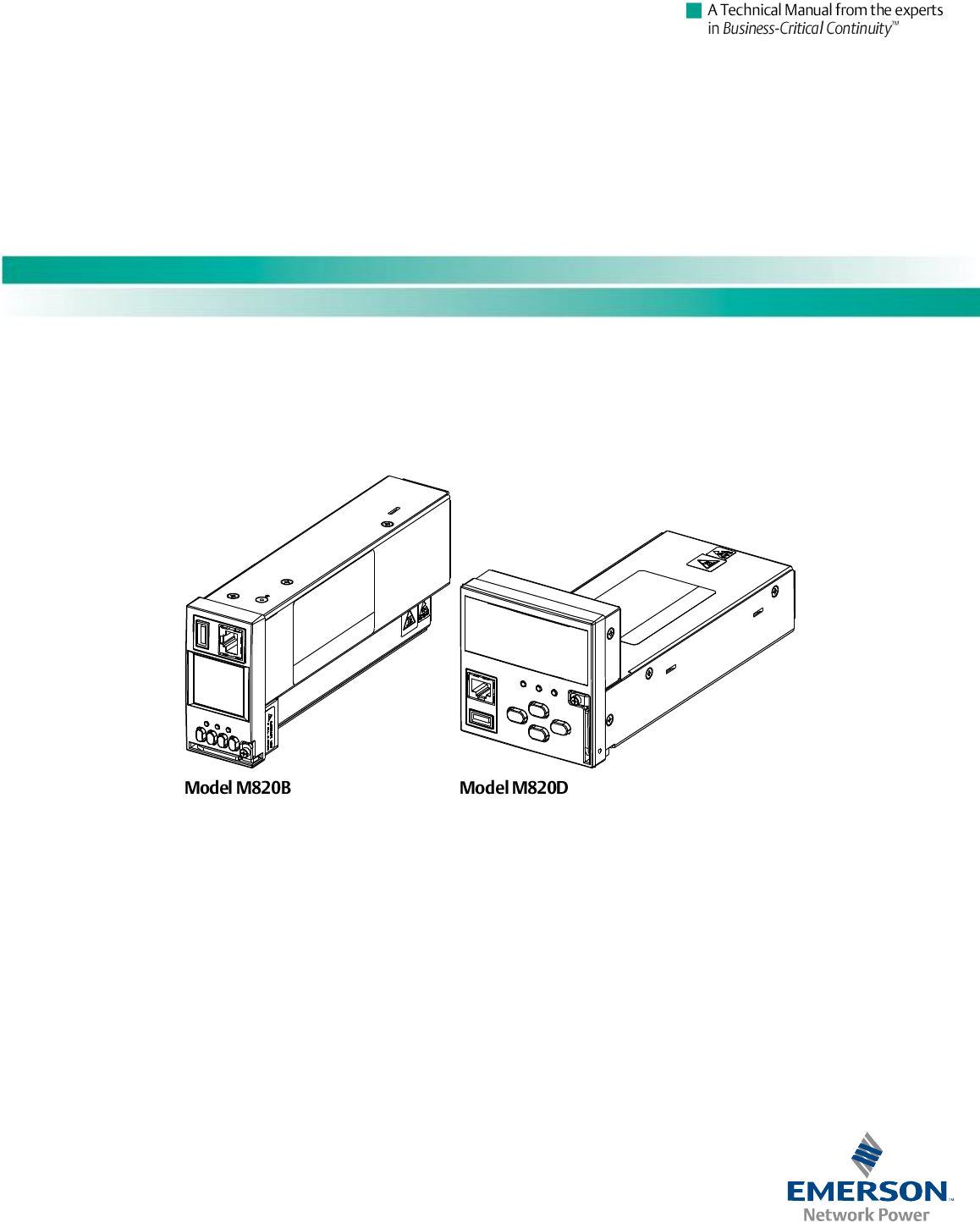
Model Number: M820B, M820D
This page is intentionally blank.

User Instructions UM1M820BNA
Spec No. 1M820BNA (Model M820B) Issue AH, March 4, 2013
Spec No. 1M820DNA (Model M820D)
Table of Contents i
This document is property of Emerson Network Power, Energy Systems, North America, Inc. and contains confidential and proprietary information owned by Emerson Network Power, Energy
Systems, North America, Inc. Any copying, use, or disclosure of it without the written permission of Emerson Network Power, Energy Systems, North America, Inc. is strictly prohibited.
TABLE OF CONTENTS
Chapter 1. Introduction .......................................................................................................... 1
1.1 Preface ......................................................................................................................................................... 1
1.2 Overview....................................................................................................................................................... 1
1.3 Function Descriptions ................................................................................................................................... 2
1.3.1 Rectifier Control ................................................................................................................................ 2
1.3.2 Converter Control ............................................................................................................................. 2
1.3.3 System Components Monitoring and System Alarms Generation ................................................... 3
1.3.4 Operating Data Acquisition and Data Logs ...................................................................................... 3
1.3.5 Battery Management ........................................................................................................................ 4
1.3.6 Intelligent Power Matching (Energy Optimization Mode) ................................................................. 8
1.3.7 Power Split Feature .......................................................................................................................... 9
1.3.8 Diesel Management Feature ............................................................................................................ 9
1.3.9 PLC (Programmable Logic Controller) Function ............................................................................ 10
1.3.10 Supervisory Module (SM Modules) Monitoring .............................................................................. 10
1.3.11 Hybrid Control Function .................................................................................................................. 10
1.3.12 Maximum Current Limit Function.................................................................................................... 15
Chapter 2. Operation ............................................................................................................ 16
2.1 Local Indicators .......................................................................................................................................... 16
2.2 Passwords and Access Levels ................................................................................................................... 17
2.3 Local Keypad and Display Access ............................................................................................................. 18
2.3.1 Local Menu Navigation Keys and LCD Display .............................................................................. 18
2.3.2 Local Display Menus ...................................................................................................................... 18
2.4 WEB Interface Access ................................................................................................................................ 19
2.4.1 Overview ......................................................................................................................................... 19
2.4.3 WEB Interface Menus ..................................................................................................................... 19
2.4.4 Connecting the Controller Locally (via the Ethernet Port) .............................................................. 19
2.4.5 Disabling Proxy Server Settings to Enable a Connection to the Controller over an Intranet
Network (if required) ....................................................................................................................... 20
2.4.6 Logging into the Controller ............................................................................................................. 21
2.5 Common Tasks Performed via the Local Keypad and/or Web Interface ................................................... 22
2.5.1 Backing Up the Configuration ......................................................................................................... 22
2.5.2 Reloading a Backed-Up Configuration ........................................................................................... 22
2.5.3 Reloading the Configuration File Stored in the ACU+ Controller ................................................... 22
2.5.4 Downloading a Configuration or an Application ("All") Package into the ACU+ Controller ............ 23
2.5.5 Rebooting the Controller ................................................................................................................. 24
2.5.6 Changing the Local LCD Display Contrast ..................................................................................... 24
2.5.7 Disabling the Local Keypad Sound ................................................................................................ 24
2.5.8 Changing the Date .......................................................................................................................... 24
2.5.9 Changing the Time ......................................................................................................................... 24
2.5.10 Adding, Deleting, and Modifying Users .......................................................................................... 24
2.5.11 Assigning Severity Level to Alarms ................................................................................................ 24

UM1M820BNA User Instructions
Issue AH, March 4, 2013 Spec No. 1M820BNA (Model M820B)
Spec No. 1M820DNA (Model M820D)
ii Table of Contents
This document is property of Emerson Network Power, Energy Systems, North America, Inc. and contains confidential and proprietary information owned by Emerson Network Power, Energy
Systems, North America, Inc. Any copying, use, or disclosure of it without the written permission of Emerson Network Power, Energy Systems, North America, Inc. is strictly prohibited.
2.5.12 Assigning Relays to Alarms ............................................................................................................ 25
2.5.13 Changing the Names of Items Displayed in the LCD and Web-Interface Menus .......................... 25
2.5.14 Viewing Alarms ............................................................................................................................... 25
2.5.15 Clearing Rectifier Lost, Rectifier Communication Fail, Converter Lost, Converter
Communication Fail, and All Converter Comm Fail Alarms ........................................................... 25
2.5.16 Clearing SMTemp Lost and SMTemp Probe Alarms ..................................................................... 25
2.5.17 Clearing Battery Alarms .................................................................................................................. 25
2.5.18 Clearing Logs.................................................................................................................................. 25
2.5.19 Clearing the Maintenance Alarm .................................................................................................... 26
2.5.20 Viewing the ACU+ Controller’s Device Inventory ........................................................................... 26
2.5.21 Updating the ACU+ Controller’s Device Inventory ......................................................................... 26
2.5.22 Programming the Audible Alarm Feature ....................................................................................... 26
2.5.23 Blocking Alarms .............................................................................................................................. 26
2.5.24 Configuring the ACU+ Identification of Rectifiers and Assigning which Input Phase is
Connected to the Rectifiers ............................................................................................................ 27
2.5.25 Configuring the ACU+ Identification of Converters ........................................................................ 28
2.5.26 Viewing/Changing the Float Voltage Setting .................................................................................. 29
2.5.27 Viewing/Changing the Equalize Voltage Setting ............................................................................ 29
2.5.28 Setting Digital Inputs ....................................................................................................................... 29
2.5.29 Setting Temperature Sensors ......................................................................................................... 29
2.5.30 Setting Battery Charge Temperature Compensation ..................................................................... 30
2.5.31 Setting Auto Equalize ..................................................................................................................... 30
2.5.32 Setting Battery Parameters ............................................................................................................ 31
2.5.34 Setting Battery Block and Battery Midpoint Monitoring (if equipped with an EIB Assembly) ......... 31
2.5.35 Setting IP Communications Parameters ........................................................................................ 31
2.5.36 Setting External Shunts (connected to the EIB Assembly) ............................................................ 31
2.5.37 Setting External Shunts (connected to the SM-DU+ Assembly) .................................................... 31
2.5.38 Setting the Load Current Alarm ...................................................................................................... 32
2.5.39 Placing the System in Float or Equalize Charge Mode .................................................................. 32
2.5.40 Manually Forcing Relays ................................................................................................................ 32
2.5.41 Manually Forcing LVDs .................................................................................................................. 32
2.5.42 Using the Relay Test Feature ......................................................................................................... 33
2.5.43 Spec. No. 588820300 Battery Rack System (Lithium Ion Battery Configuration) .......................... 34
2.6 Available Alarms ......................................................................................................................................... 35
2.7 Power Split Feature .................................................................................................................................... 73
2.7.1 Overview ......................................................................................................................................... 73
2.7.2 How Power Split Works .................................................................................................................. 73
2.7.3 Operating Modes ............................................................................................................................ 74
2.7.4 Requirements and Conditions ........................................................................................................ 74
2.7.5 Paralleling the Existing and ACU+ Power Systems ....................................................................... 75
2.7.6 Programming the ACU+ Power Split Feature ................................................................................ 77
2.7.7 Verifying the Operation of the Power Split Feature ........................................................................ 79
Chapter 3. Local Display Menus .......................................................................................... 80
3.1 Overview..................................................................................................................................................... 80

User Instructions UM1M820BNA
Spec No. 1M820BNA (Model M820B) Issue AH, March 4, 2013
Spec No. 1M820DNA (Model M820D)
Table of Contents iii
This document is property of Emerson Network Power, Energy Systems, North America, Inc. and contains confidential and proprietary information owned by Emerson Network Power, Energy
Systems, North America, Inc. Any copying, use, or disclosure of it without the written permission of Emerson Network Power, Energy Systems, North America, Inc. is strictly prohibited.
3.2 Menus ......................................................................................................................................................... 80
3.2.1 Adjustment Range Restrictions ...................................................................................................... 81
3.3 Description of Local Display (and Web Interface) Menus Line Items ........................................................ 92
3.3.1 Settings Menu ................................................................................................................................. 92
3.3.2 ECO Mode (Energy Optimization) Menu ...................................................................................... 106
3.3.3 Manual Menu ................................................................................................................................ 106
3.3.4 Quick Setting Menu ...................................................................................................................... 109
Chapter 4. WEB Interface Menus ....................................................................................... 113
4.1 Overview................................................................................................................................................... 113
4.2 Homepage ................................................................................................................................................ 113
4.3 Menu Navigation Window......................................................................................................................... 115
4.3.1 Alarms ........................................................................................................................................... 116
4.4 Device Information Menu ......................................................................................................................... 118
4.4.1 Rectifier Group.............................................................................................................................. 118
4.4.2 Battery Group (except Li-Ion Battery Configuration) .................................................................... 123
4.4.3 Battery Group (Li-Ion Battery Configuration) ................................................................................ 128
4.5 Quick Settings Menu ................................................................................................................................ 130
4.6 Query Menu .............................................................................................................................................. 131
4.6.1 Alarm History Log Sub-Menu ....................................................................................................... 131
4.6.2 Data History Log Sub-Menu ......................................................................................................... 132
4.6.3 Control/System/Diesel Log Sub-Menu ......................................................................................... 133
4.6.4 Battery Test Log Sub-Menu .......................................................................................................... 134
4.7 Maintenance Menu ................................................................................................................................... 135
4.7.1 Network Configuration Sub-Menu ................................................................................................ 135
4.7.2 NMS (Network Management System) Configuration Sub-Menu .................................................. 136
4.7.3 HLMS (High Level Management System) Configuration Sub-Menu ............................................ 137
4.7.4 Edit PowerSplit Sub-Menu ............................................................................................................ 138
4.7.5 User Information Settings Sub-Menu ........................................................................................... 139
4.7.6 Clear Data Sub-Menu ................................................................................................................... 141
4.7.7 Restore Factory Defaults Sub-Menu ............................................................................................ 142
4.7.8 Download Sub-Menu .................................................................................................................... 143
4.7.9 Retrieve ‘SettingParam.run’ File Sub-Menu ................................................................................. 145
4.7.10 Time Sync Sub-Menu ................................................................................................................... 146
4.7.11 System Inventory Sub-Menu ........................................................................................................ 147
4.8 Configuration Menu .................................................................................................................................. 148
4.8.1 Auto Configuration Sub-Menu ...................................................................................................... 148
4.8.2 Site Information Modification Sub-Menu ...................................................................................... 149
4.8.3 Equipment Information Modification Sub-Menu ........................................................................... 150
4.8.4 Signal Information Modification Sub-Menu ................................................................................... 151
4.8.5 Alarm Suppressing Sub-Menu...................................................................................................... 153
4.8.6 PLC Sub-Menu ............................................................................................................................. 155
4.8.7 Alarm Relay Sub-Menu ................................................................................................................ 158

UM1M820BNA User Instructions
Issue AH, March 4, 2013 Spec No. 1M820BNA (Model M820B)
Spec No. 1M820DNA (Model M820D)
iv Table of Contents
This document is property of Emerson Network Power, Energy Systems, North America, Inc. and contains confidential and proprietary information owned by Emerson Network Power, Energy
Systems, North America, Inc. Any copying, use, or disclosure of it without the written permission of Emerson Network Power, Energy Systems, North America, Inc. is strictly prohibited.
Chapter 5. Accessing the Controller via a Network Management System (NMS) ......... 159
5.1 General ..................................................................................................................................................... 159
5.2 NMS Supported by SNMP Agent ............................................................................................................. 159
5.3 MIB Installation ......................................................................................................................................... 159
5.3.1 Installation ..................................................................................................................................... 159
5.3.2 Contents of the Controller’s MIB................................................................................................... 159
5.4 Accessing the Controller through an NMS ............................................................................................... 163
5.4.1 Apply Administrative Authority ...................................................................................................... 163
Chapter 6. Replacement Procedures ................................................................................ 164
6.1 ACU+ Controller Replacement ................................................................................................................. 164
Chapter 7. Specifications ................................................................................................... 166
Revision Record ................................................................................................................... 168

User Instructions UM1M820BNA
Spec No. 1M820BNA (Model M820B) Issue AH, March 4, 2013
Spec No. 1M820DNA (Model M820D)
Chapter 1. Introduction 1
This document is property of Emerson Network Power, Energy Systems, North America, Inc. and contains confidential and proprietary information owned by Emerson Network Power, Energy
Systems, North America, Inc. Any copying, use, or disclosure of it without the written permission of Emerson Network Power, Energy Systems, North America, Inc. is strictly prohibited.
CHAPTER 1. INTRODUCTION
1.1 Preface
These instructions describe the complete functionality of the ACU+ Controller. Some functionality is
dependent on hardware connected to the ACU+ Controller. Your system may not utilize all the
functionality described.
Refer also to the ACU+ Configuration Drawing (C-drawing) furnished with your system for a list of factory
default settings.
1.2 Overview
The ACU+ Controller performs the following functions.
Rectifier Control, including an Energy Optimization Mode
Converter Control
System Components Monitoring and System Alarms Generation
(including recording alarms in logs)
Operating Data Acquisition and Data Logs
Battery Management
Intelligent Power Matching (Energy Optimization Mode)
Power Split Feature
Diesel Management Feature
PLC (Programmable Logic Controller) Function
Supervisory Module (SM Modules) Monitoring
Hybrid Control Function
Maximum Current Limit Function
The ACU+ controls the system automatically via configured parameters.
A User interfaces with the ACU+ Controller locally using the local keypad and LCD display or
locally/remotely using the WEB Interface.
The ACU+ Controller can also be accessed via SNMP (v1 and v2).
UM1M820BNA User Instructions
Issue AH, March 4, 2013 Spec No. 1M820BNA (Model M820B)
Spec No. 1M820DNA (Model M820D)
2 Chapter 1. Introduction
This document is property of Emerson Network Power, Energy Systems, North America, Inc. and contains confidential and proprietary information owned by Emerson Network Power, Energy
Systems, North America, Inc. Any copying, use, or disclosure of it without the written permission of Emerson Network Power, Energy Systems, North America, Inc. is strictly prohibited.
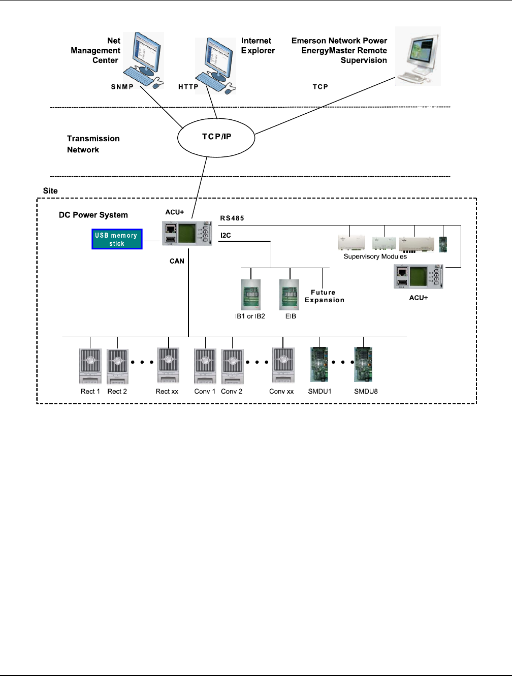
Figure 1 illustrates the various methods to interface with the ACU+ Controller remotely.
Figure 1
ACU+ Remote Communications
1.3 Function Descriptions
1.3.1 Rectifier Control
Rectifiers are automatically controlled by the ACU+ Controller. The ACU+ Controller provides an Energy
Optimization Mode function. Energy Optimization permits an installation to only operate rectifiers as
needed to maintain the load and keep batteries in a fully charged condition. As load increases, Energy
Optimization turns on additional rectifiers as needed to maintain the load. As load decreases, Energy
Optimization places rectifiers in standby to conserve energy usage. Rectifiers which are always operating
to maintain any load requirements are cycled through the group of rectifiers controlled by this feature to
provide uniform operating times for each rectifier.
1.3.2 Converter Control
Converters are automatically controlled by the ACU+ Controller.

User Instructions UM1M820BNA
Spec No. 1M820BNA (Model M820B) Issue AH, March 4, 2013
Spec No. 1M820DNA (Model M820D)
Chapter 1. Introduction 3
This document is property of Emerson Network Power, Energy Systems, North America, Inc. and contains confidential and proprietary information owned by Emerson Network Power, Energy
Systems, North America, Inc. Any copying, use, or disclosure of it without the written permission of Emerson Network Power, Energy Systems, North America, Inc. is strictly prohibited.
1.3.3 System Components Monitoring and System Alarms Generation
The ACU+ Controller monitors the components comprising the system (such as the rectifiers, converters,
and supervisory modules) and generates alarms if a fault condition occurs. The ACU+ Controller also
maintains an alarm history log.
The available system alarms are programmed with an Alarm Severity Level. Each Alarm Severity Level
has different visual/audible alarm attributes. Available Alarm Severity Levels and their attributes are listed
in Table 1.
Alarm
Severity Level
ACU+ Red
Alarm Indicator
ACU+ Yellow
Alarm Indicator
ACU+
Audible Alarm
Critical Alarm (CA)
ON
OFF
ON
Major Alarm (MJ)
ON
OFF
ON
Minor Alarm (MN)
OFF
ON
OFF
No Alarm
OFF
OFF
OFF
Table 1
Alarm Severity Levels
The alarm indicator turns OFF if the fault(s) that triggered the alarm clears.
The audible alarm can be silenced by pressing any key on the ACU+ Controller local interface pad.
The audible alarm is also silenced if the fault(s) that triggered the alarm clears.
An audible alarm cutoff feature can be programmed that silences the audible alarm after a pre-set
programmable time period. The audible alarm can also be disabled.
The available system alarms can also be mapped to alarm relays (located on ACU+ interface boards) that
can be wired to external alarm circuits.
1.3.4 Operating Data Acquisition and Data Logs
The ACU+ Controller acquires and analyses real time data from the system’s components such as the
rectifiers, converters, and supervisory modules.
The ACU+ Controller uses this data to process alarms and also records data in logs. The logs are viewed
using the WEB Interface and consists of...
Alarm History Log: records 600 latest alarms.
Data History Log: records 60000 latest history data.
Control Log: records 500 latest control events.
System Log: records 3000 latest system events.
Diesel Test Log: records 500 latest diesel test results.
Battery Test Log: up to twelve (12) battery discharge tests can be performed and recorded per year.
Note: Once maximum number of log entries is reached, new entries overwrite oldest entries.
Logs can be saved in the text (.txt) format.

UM1M820BNA User Instructions
Issue AH, March 4, 2013 Spec No. 1M820BNA (Model M820B)
Spec No. 1M820DNA (Model M820D)
4 Chapter 1. Introduction
This document is property of Emerson Network Power, Energy Systems, North America, Inc. and contains confidential and proprietary information owned by Emerson Network Power, Energy
Systems, North America, Inc. Any copying, use, or disclosure of it without the written permission of Emerson Network Power, Energy Systems, North America, Inc. is strictly prohibited.
1.3.5 Battery Management
General Battery Management
The ACU+ Controller provides the following battery management functions
(except Lithium Ion Battery Configuration).
Battery Charge Temperature Compensation
Battery Equalize Charge
Battery Charge Current Limit
High and Low Battery Temperature Alarms
Battery Thermal Runaway Management (BTRM) Feature
(Reduces Voltage during a High Battery Temperature Condition)
Battery Discharge Tests
Battery Test Logs (maximum twelve [12] logs, maximum eighteen [18] battery strings per log)
Battery LVD (Low Voltage Disconnect)
Battery Capacity Prediction
Battery Block and Battery Midpoint Monitoring
Enhanced Battery Monitoring with SM-BRC
Thermal Runaway Detection/Management
Spec. No. 588820300 Battery Rack System (Lithium Ion Battery Configuration)
When the ACU+ is equipped with the Lithium Ion Battery Configuration for use with Spec. No. 588820300
NetSure™ Battery Rack System, the battery management functions are as follows.
The configuration only provides the battery float charge voltage (equalize charging is not applicable).
The only adjustable battery setting (besides the float voltage level) is the ABCL (Active Battery
Charge Current Limit) Point.
Active Battery Charge Current Limit (ABCL): This feature controls the amount of charge current
supplied to the lithium-ion batteries installed in the power plant to prevent failure of the batteries.
Battery status and alarms sent by the batteries to the ACU+ are displayed in the ACU+ interfaces.
Refer also to the instructions provided by the battery manufacturer for battery management functions
built into the battery itself.
NOTE THAT THE FOLLOWING DESCRIPTIONS ARE FOR THE GENERAL BATTERY
MANAGEMENT FUNCTIONS AND DO NOT APPLY TO THE LITHIUM ION BATTERY
CONFIGURATION.
User Instructions UM1M820BNA
Spec No. 1M820BNA (Model M820B) Issue AH, March 4, 2013
Spec No. 1M820DNA (Model M820D)
Chapter 1. Introduction 5
This document is property of Emerson Network Power, Energy Systems, North America, Inc. and contains confidential and proprietary information owned by Emerson Network Power, Energy
Systems, North America, Inc. Any copying, use, or disclosure of it without the written permission of Emerson Network Power, Energy Systems, North America, Inc. is strictly prohibited.
Battery Charge Temperature Compensation
The ACU+ Controller can be programmed to automatically increase or decrease system output voltage to
maintain battery float current as battery temperature decreases or increases, respectively. Battery life can
be extended when an optimum charge voltage to the battery with respect to temperature is maintained.
Temperature is monitored by a sensor mounted on the battery. See your power system documentation for
temperature sensor information. You can also set High2, High1, and Low compensation temperature
alarms.
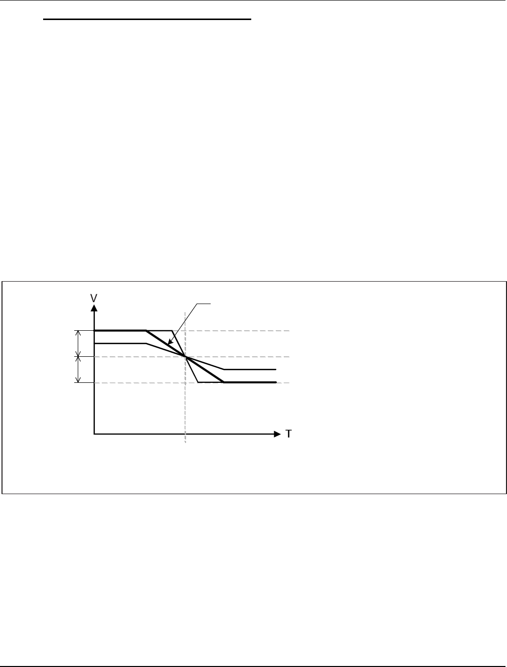
Functional Description (See Figure 2): Battery charge temperature compensation adds a correction
term, related to the temperature of the batteries, to the nominal value of the system voltage. The degree of
regulation (TempComp Coeff), expressed in mV/°C/battery string, can be set per battery manufacturer
recommendations.
To protect batteries and voltage-sensitive loads, compensation is automatically limited to a maximum of
two volts (48V systems) or one volt (24 volt systems) above or below the nominal output level (float
setting).
Temperature compensation will also clamp if the voltage reaches either the TEMP COMP MAX V setting
or the TEMP COMP MIN V setting. This feature can also be disabled.
Temperature compensation is automatically disabled if communication between the Controller and all
rectifiers is lost, a DC over or under voltage alarm activates, a low voltage disconnection occurs, manual
mode is entered, or the system enters the boost or test modes.
Figure 2
Temperature Compensated Voltage Control
TempComp Coeff
setting (mV/°C).
nom
T
nom
T
Vnom
Vhigh
Vlow
Upper voltage level where temperature compensation
clamps the voltage. Limited to the TEMP COMP MAX V
setting.
Nominal voltage (voltage at nominal temperature).
Lower voltage level where temperature compensation
clamps the voltage. Limited to the TEMP COMP MIN V
setting.
Nominal temperature (no temperature compensation is done at this temperature).
This is the Temp Comp setting.
1V Max (24V System)
2V Max (48V System)
1V Max (24V System)
2V Max (48V System)
UM1M820BNA User Instructions
Issue AH, March 4, 2013 Spec No. 1M820BNA (Model M820B)
Spec No. 1M820DNA (Model M820D)
6 Chapter 1. Introduction
This document is property of Emerson Network Power, Energy Systems, North America, Inc. and contains confidential and proprietary information owned by Emerson Network Power, Energy
Systems, North America, Inc. Any copying, use, or disclosure of it without the written permission of Emerson Network Power, Energy Systems, North America, Inc. is strictly prohibited.
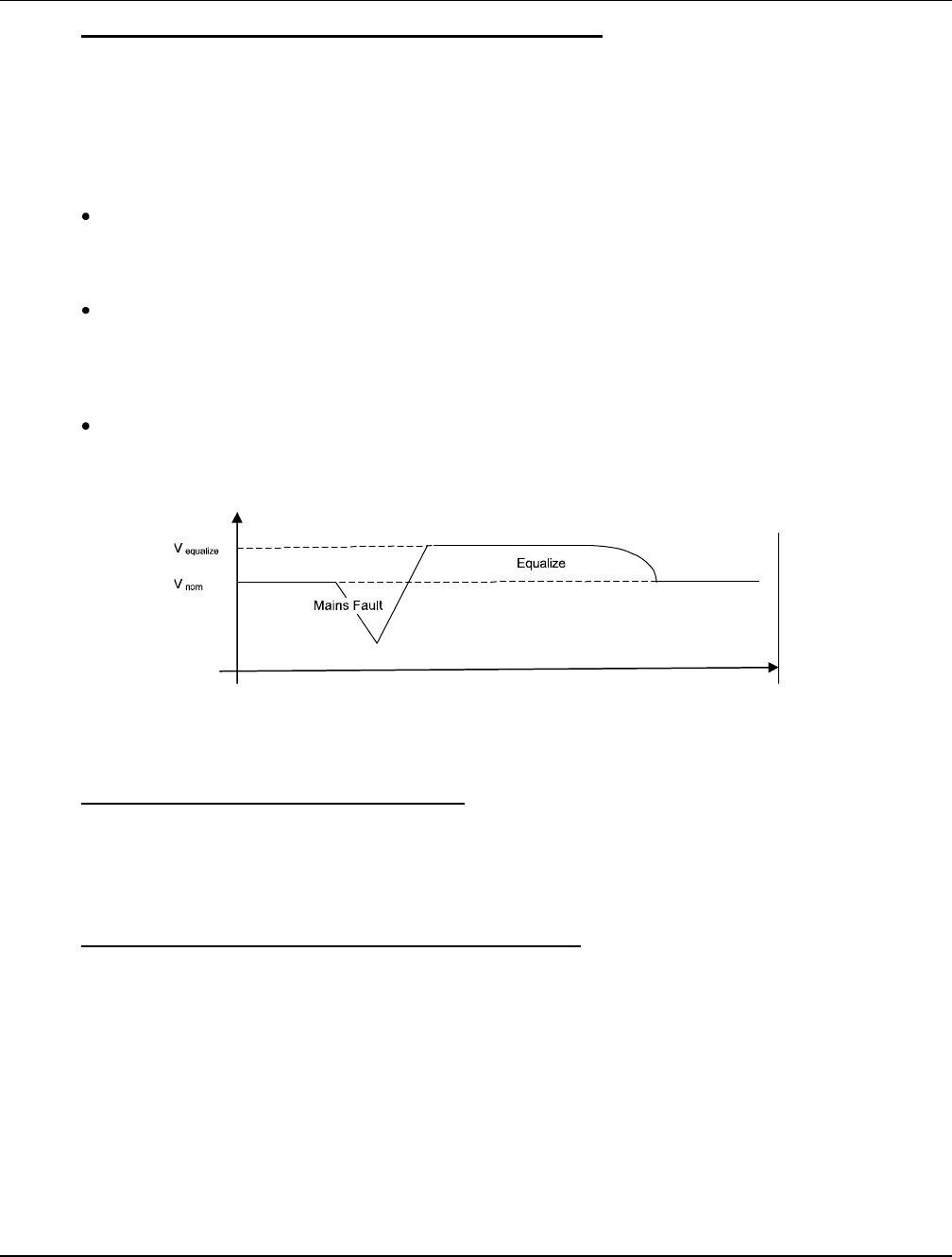
Battery Equalize Charge and Battery Charge Current Limit
The ACU+ Controller can increase system output voltage for equalizing the charge on all battery cells of a
conventional flooded cell battery, or for recharging the battery following a commercial power failure.
The charging function can be initiated cyclically (scheduled), automatically, or manually.
Refer to the battery manufacturer's instructions for equalize charging instructions.
Functional Description (See Figure 3):
Start of Charging: When the battery charge current exceeds a preset value for 3 minutes or if the
calculated battery capacity has decreased to a preset value (after a commercial AC failure, for
example), the charging function of the ACU+ is activated. A charging signal is sent from the ACU+ to
the rectifiers to increase the voltage up to the battery charging level Vequalize
Battery Current Limitation: After a commercial AC failure or when some battery cells are
permanently damaged, the current to the batteries can be quite extensive. To avoid overheating or
further damages to the battery, the ACU+ limits the battery current to a preset level by limiting the
charging voltage of the rectifiers. Should the battery current still exceed a higher preset value, an
alarm is issued.
End of Charging: When the charging current drops below a preset value, a defined prolonged
charging time is started before the charging is stopped and the voltage of the rectifiers return to the
float charging level (Vnom). For safety, there is a equalize charging limit time that stops the charging
after a preset time.
Figure 3
Voltage Characteristics on Commercial AC Failure and Automatic Equalize Charging
High and Low Battery Temperature Alarms
The ACU+ Controller can monitor battery temperature via a temperature sensor mounted on a battery cell.
Values for high battery temperature and low battery temperature alarms can then be programmed into the
ACU+ Controller.
Battery Thermal Runaway Management (BTRM) Feature
You can designate a temperature sensor as the BTRM sensor. The BTRM sensor has High2 and High1
BTRM temperature alarm limits. If battery temperature exceeds the “BTRM Temp High2” setting, system
voltage is lowered to the BTRM voltage setting. This feature can also be disabled.
User Instructions UM1M820BNA
Spec No. 1M820BNA (Model M820B) Issue AH, March 4, 2013
Spec No. 1M820DNA (Model M820D)
Chapter 1. Introduction 7
This document is property of Emerson Network Power, Energy Systems, North America, Inc. and contains confidential and proprietary information owned by Emerson Network Power, Energy
Systems, North America, Inc. Any copying, use, or disclosure of it without the written permission of Emerson Network Power, Energy Systems, North America, Inc. is strictly prohibited.
Battery Discharge Test and Battery Test Logs
The ACU+ Controller can perform battery discharge tests to check the condition of the battery.
There are (3) types of battery discharge tests.
Short Time Test
Time Test
Stable Current Test
A User can manually start a battery discharge test or program the ACU+ Controller to automatically start
battery discharge tests at scheduled intervals (cyclic battery tests). During a battery discharge test, the
ACU+ Controller controls the rectifiers output to place the entire load or partial load on the batteries. The
ACU+ Controller monitors the discharge of the battery and saves the results in a battery test log.
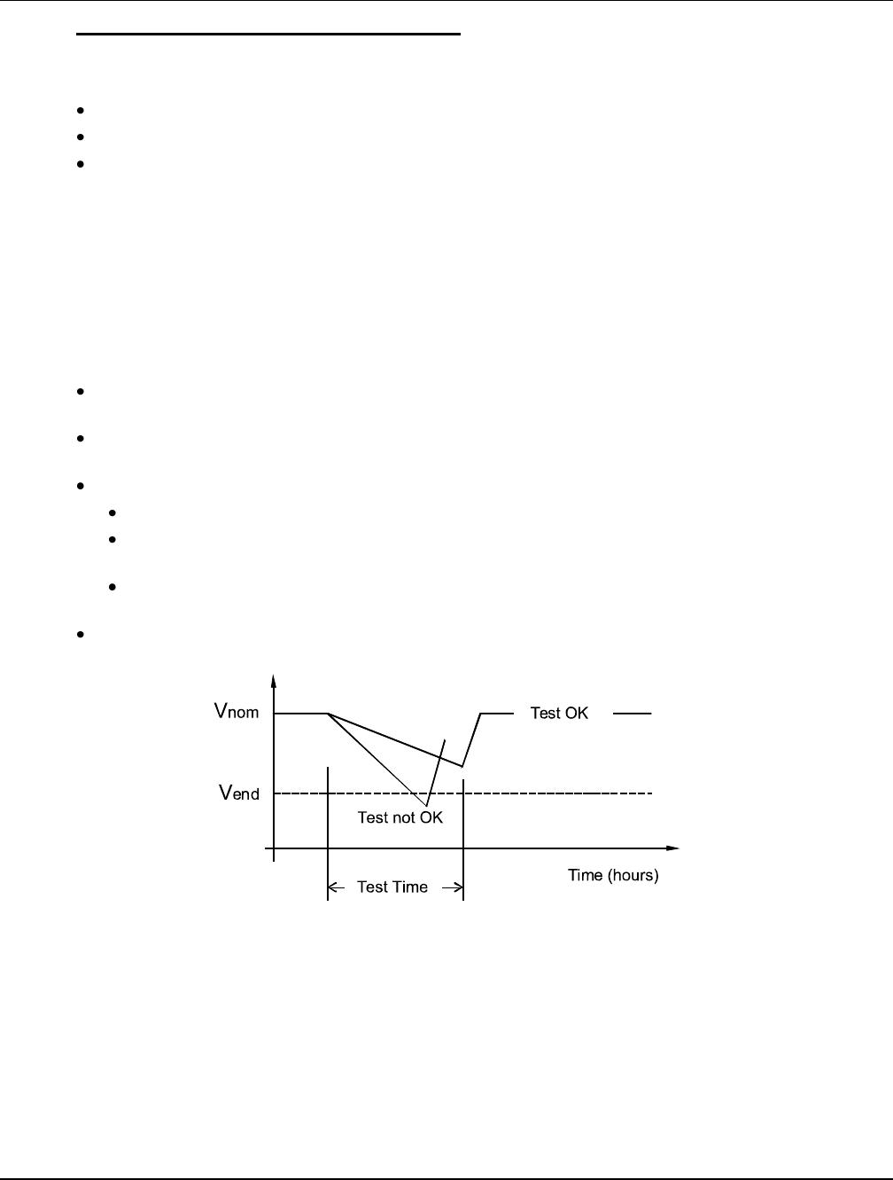
Functional Description: For manual battery discharge tests as well as for cyclic battery discharge tests,
the following parameters must be set: End Voltage, Test Time, and Battery Capacity Discharge Limit. See
Figure 4.
Battery Discharge Test Sequence:
In time test modes, the output voltage of the rectifiers is reduced so that only the batteries power the
load. If the batteries fail, the rectifiers power the load.
In stable current test mode, the output voltage of the rectifiers is reduced so that the batteries supply
the preset test current to the load.
The battery test continues until one of the following occurs:
The preset test time, see Figure 4, expires. The battery has passed the test.
The battery voltage drops below the preset end voltage level (Vend) (Figure 4). The battery has not
passed the test and the test is interrupted. A battery test alarm is activated.
The battery capacity drops below the preset test end battery capacity. The battery has not passed
the test and the test is interrupted. A battery test alarm is activated.
After the battery discharge test, the output voltage of the rectifiers increase so that the rectifiers supply
the system and charge the batteries.
Figure 4
Battery Test Diagram

UM1M820BNA User Instructions
Issue AH, March 4, 2013 Spec No. 1M820BNA (Model M820B)
Spec No. 1M820DNA (Model M820D)
8 Chapter 1. Introduction
This document is property of Emerson Network Power, Energy Systems, North America, Inc. and contains confidential and proprietary information owned by Emerson Network Power, Energy
Systems, North America, Inc. Any copying, use, or disclosure of it without the written permission of Emerson Network Power, Energy Systems, North America, Inc. is strictly prohibited.
Battery LVD (Low Voltage Disconnect)
To prevent serious damage to the batteries during a commercial AC power failure, the batteries can be
disconnected by voltage or time control.
The batteries are reconnected automatically when commercial AC power is restored and a predetermined
DC voltage level is reached.
Voltage Controlled Disconnection: When the set voltage level is reached, the batteries are
disconnected.
Time Controlled Disconnection: When the set time has elapsed, the batteries are disconnected.
Battery Capacity Prediction
The ACU+ can predict battery capacity.
Battery Block and Battery Midpoint Monitoring
The ACU+ can monitor battery blocks (12V blocks) or midpoint battery voltage of battery strings
connected to the EIB assembly. An alarm is issued when either battery block voltage or battery midpoint
voltage is abnormal.
Enhanced Battery Monitoring with SM-BRC
When connected to an SM-BRC, the ACU+ provides enhanced battery monitoring.
Thermal Runaway Detection and Management
Functional Description: The system uses several control mechanisms to avoid thermal runaway.
First: During a short high rate discharge, the batteries will normally get hot. The ACU+ takes this into
consideration. After completion of the discharge duty, the batteries are recharged with a limited current to
avoid heating the batteries any further.
Second: The temperature of the batteries can be monitored, and the ACU+ sets the charge voltage
appropriately, as previously described under Battery Charge Temperature Compensation.
Third: In addition to battery temperature compensation, if battery temperature rises above a set
temperature limit, the system stops battery charging completely by lowering the output voltage to the
“BTRM Voltage” setting. This allows the batteries to cool down. The system also provides alarm
notification of this occurrence. Power supplied to customer equipment is not interrupted.
Fourth: The battery LVD circuits can be programmed to open (disconnect) if a high temperature event
occurs (HTD – High Temperature Disconnect). The contactor(s) open when battery temperature rises
above a programmable value and close again when battery temperature falls below another
programmable value.
1.3.6 Intelligent Power Matching (Energy Optimization Mode)
With Energy Optimization Mode (ECO):
The Controller monitors load current versus system capacity.
The Controller commands some rectifiers to standby in rotation.
Refer to “1.3.1 Rectifier Control” for further description.
User Instructions UM1M820BNA
Spec No. 1M820BNA (Model M820B) Issue AH, March 4, 2013
Spec No. 1M820DNA (Model M820D)
Chapter 1. Introduction 9
This document is property of Emerson Network Power, Energy Systems, North America, Inc. and contains confidential and proprietary information owned by Emerson Network Power, Energy
Systems, North America, Inc. Any copying, use, or disclosure of it without the written permission of Emerson Network Power, Energy Systems, North America, Inc. is strictly prohibited.
1.3.7 Power Split Feature
The Power Split feature allows you to connect the power system controlled via the ACU+ to an existing DC
power system instead of extending or completely replacing the existing DC power system.
The power system controlled via the ACU+ functions as a slave system to share load (split output) with the
existing system (master system) that requires expansion. The ACU+ does not require communication with
the master system’s Controller.
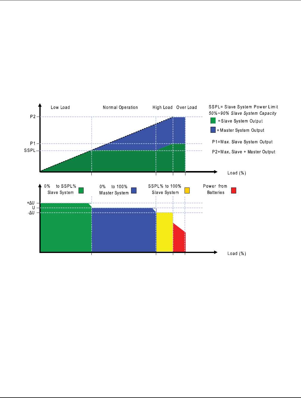
The Power Split feature provides for the sharing of total load in a controlled manner between the
paralleled power systems.
When Power Split is programmed, the ACU+ adjusts rectifier output voltage per load demands to ensure
proper sharing between the slave and master power systems. See Figure 5.
Figure 5
Power Split Feature
1.3.8 Diesel Management Feature
The Diesel Management feature is available when an SM-AC supervisory module is connected to the
ACU+ Controller. The Diesel Management feature consists of a Diesel Test. The Diesel Test can be
performed at specific intervals or a User can manually start the Diesel Test. The ACU+ records the test
results.

UM1M820BNA User Instructions
Issue AH, March 4, 2013 Spec No. 1M820BNA (Model M820B)
Spec No. 1M820DNA (Model M820D)
10 Chapter 1. Introduction
This document is property of Emerson Network Power, Energy Systems, North America, Inc. and contains confidential and proprietary information owned by Emerson Network Power, Energy
Systems, North America, Inc. Any copying, use, or disclosure of it without the written permission of Emerson Network Power, Energy Systems, North America, Inc. is strictly prohibited.
1.3.9 PLC (Programmable Logic Controller) Function
The PLC function allows a User to create "control program lines" by combining equipment analog signals,
parameters, and alarms in a sequence that controls equipment and/or operates relays.
Control program lines are created using the WEB Interface. See “4.8.6. PLC Sub-Menu”.
Available logical components are:
Logical Component
Description
Logic NOT
NOT; Returns the inverted value of the input signal/parameter.
Logic OR
OR; Returns active (true) if any of the two signals/parameters are active (true).
Logic AND
AND; Returns active (true) if both of the two signals/parameters are active
(true).
AndOr
XOR; Returns active (true) if one and only one of the two signals/parameters
are active (true).
Greater Than (>)
GREATER THAN; Returns active (true) if the analog input signal goes above
the set threshold. Returns inactive (false) if the input signal goes below the set
threshold minus hysteresis value.
Less Than (<)
LESS THAN; Returns active (true) if the analog input signal goes below the set
threshold. Returns inactive (false) if the input signal goes above the set
threshold plus hysteresis value.
Delay
DELAY in seconds; Delays the applied signal/parameter with the defined time in
seconds before applying it to the output.
1.3.10 Supervisory Module (SM Modules) Monitoring
Various devices (supervisory modules) can be connected to the ACU+ Controller to extend its monitoring
capabilities.
1.3.11 Hybrid Control Function
Hybrid Control is designed for use in new installations or as an upgrade of existing sites powered by a
diesel generator(s) when grid power is not available. The Hybrid Control is also applicable to sites with
highly unreliable or frequently unavailable grid power connection. The primary power source is still
considered to be the diesel generator(s).
Note: The Hybrid Control function requires a specific configuration. Hybrid Control menus will not
normally be displayed unless your ACU+ has been configured by Emerson for this function.
Contact Emerson for a Hybrid Control configuration.
General
Hybrid Control allows the option of selecting one of the following: Fixed Daily Time based operation or
Capacity Discharge based operation.

User Instructions UM1M820BNA
Spec No. 1M820BNA (Model M820B) Issue AH, March 4, 2013
Spec No. 1M820DNA (Model M820D)
Chapter 1. Introduction 11
This document is property of Emerson Network Power, Energy Systems, North America, Inc. and contains confidential and proprietary information owned by Emerson Network Power, Energy
Systems, North America, Inc. Any copying, use, or disclosure of it without the written permission of Emerson Network Power, Energy Systems, North America, Inc. is strictly prohibited.
Fixed Daily Time based operation is intended to be used with a combination of AC powered active
cooling (air conditioners) and DC powered cooling (heat exchangers, etc). The cycle period is
synchronized to the 24hr day-night cycle. It makes optimum use of the different temperature conditions
during the day and the night in order to facilitate Hybrid fuel saving operation.
Capacity Discharge based operation is intended for sites utilizing only DC powered cooling (heat
exchangers, etc). The cycle period is determined by User selectable depth of discharge (DOD) of the
batteries per cycle and associated recharge time. It provides optimum Hybrid fuel saving operation.
Operation from Grid Power is performed with both Fixed Daily Time and Capacity Discharge modes of
operation. Grid power is always given priority when available.
As the two types of control are specific to the hardware configuration of the site, the Fixed Daily Time or
Capacity Discharge is a User selectable option on installation.
Hybrid Operation
Generator Control: Potential free relay contact output from the ACU+ interface board controls the start
and stop of the diesel generator. The signal is generated by the ACU+ Controller and operates according
to the Hybrid software mode of operation. The control logic is as follows:
Energized output relay – Generator OFF.
De-energized output relay – Generator ON.
This is a fail-safe logic to ensure generator operation in all cases where power or control to the relay is
lost.
Further to that, the type of signal to the generator can be selected as N/O (Normally Open) or N/C
(Normally Closed) by selecting the relevant output pins of the control relay.
Number of Generator Control Outputs: The ACU+ Hybrid software can control one or two generators.
Each generator control is designated as DG1 or DG2 output. A User selectable menu will allow selecting
DG1, DG2, or DG1 and DG2. When both are selected they will be alternatively used (two generator
operation).
Diesel Fail Alarm: A diesel fail alarm will be generated if the Diesel Generator ON signal fails to bring the
generator to operation and provide the system with AC power. Alarm will be triggered after 60 seconds
(default value, settable) from ON signal. If two generator operations are selected simultaneously with the
alarm, the second Diesel Generator ON signal will be activated.
Battery Fuse Trip Alarm: In the event of a Battery Fuse trip condition an alarm will be generated.
Under Voltage Alarms:
Under Voltage Alarm 1: An Under Voltage Alarm 1 is set. If voltage decreases below this setting, an
alarm is raised.
Under Voltage Alarm 2: An Under Voltage Alarm 2 is set. If voltage decreases below this setting, the
Diesel Generator is started and an alarm is raised.
LVD 1: Normal loads are disconnected.
LVD 2: Priority loads are disconnected.
Charge Voltage:
Refer to Figure 6.
UM1M820BNA User Instructions
Issue AH, March 4, 2013 Spec No. 1M820BNA (Model M820B)
Spec No. 1M820DNA (Model M820D)
12 Chapter 1. Introduction
This document is property of Emerson Network Power, Energy Systems, North America, Inc. and contains confidential and proprietary information owned by Emerson Network Power, Energy
Systems, North America, Inc. Any copying, use, or disclosure of it without the written permission of Emerson Network Power, Energy Systems, North America, Inc. is strictly prohibited.
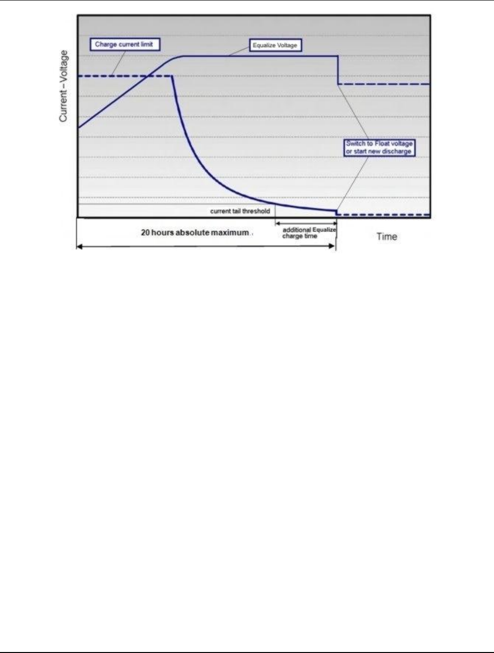
Figure 6
Charge Voltage
Equalize Charge: The battery will be recharged at equalize voltage. This is the voltage set in the initial
phase of battery recharge. See Figure 6.
As the voltage limit is reached, the charge current is gradually reduced – effect known as current tail.
When the current tail falls below a set of threshold levels, additional equalize charge time is added.
The equalize charge current tail threshold is settable from 0.01 to 0.05. Default setting is 0.02 (2A per
100Ah). The additional equalize charge time is settable from 0 hours to 7 hours (settable in minutes from
0 to 720), default setting is 4 hours. The duration of the equalize charge is determined as the time from the
start of the recharge to the end of the additional time. (Maximum charge time, determined from the time
charge starts, is settable in the range of 5-24h.)
The end of recharge is determined by a three (3) step approach:
Step1 - calculated battery capacity exceeds 90%. Calculation is performed by measurement of battery
current and time, in Ah.
Step 2 - charge current tail threshold is reached.
Step 3 - additional charge time is added.
Float Charge: Default float voltage is 54.0V at 20°C with a temperature compensation of -72mV per °C.
If battery temperature exceeds 38°C, the charge voltage is reduced to 51V to reduce gassing and prevent
thermal runaway. The same is applicable as well for equalizing charge.
Equalizing Charge: As the cyclic use does not ensure complete battery recharge after every cycle, an
equalizing charge cycle is added. The equalizing cycle will occur up to four times a month, settable for
every 7 to 60 days intervals. Start date and time is settable. Equalizing charge time is 20 hours
independent of discharge time setting. Equalizing charge is performed at equalize voltage until end of
additional equalize time and thereafter at float voltage for the remaining time. Also see Figure 6.
Equalize charge independently settable 0-720 min (already set in equalize charge).

User Instructions UM1M820BNA
Spec No. 1M820BNA (Model M820B) Issue AH, March 4, 2013
Spec No. 1M820DNA (Model M820D)
Chapter 1. Introduction 13
This document is property of Emerson Network Power, Energy Systems, North America, Inc. and contains confidential and proprietary information owned by Emerson Network Power, Energy
Systems, North America, Inc. Any copying, use, or disclosure of it without the written permission of Emerson Network Power, Energy Systems, North America, Inc. is strictly prohibited.
Early Termination of the Discharge Periods
During discharge, over temperature and under voltage conditions will interrupt the discharge and
change the operation to charge – Diesel Generator ON.
Over Temperature: The diesel generator will start and run for a period before it is stopped again. The run
time is User selectable in the range 30 to 120 minutes, default setting is 60 minutes. Temperature is
referenced to cabinet/shelter ambient temperature sensor connected to the Controller, not battery
temperature. Over temperature start can be disabled completely from User settings menu.
Under Voltage: The under voltage start is triggered by under voltage alarm 2 voltage settings.
The diesel generator will start and run until the normal recharge cycle is due to finish depending on
selected mode of operation.
Example for Fixed Daily Time: If the normal recharge cycle is from 7am until 7pm and under voltage has
started the diesel generator at 5:30am, the effective recharge will be from 5:30am until 7pm.
Example for Capacity Discharge: If this mode is selected, the recharge will terminate.
Operation with Grid Power
Grid power is always prioritized when available. If grid power becomes available during battery discharge,
the discharge cycle is terminated and recharge cycle is initiated. If grid power becomes available during
diesel generator operation, the diesel generator is switched OFF and operations continue on grid power.
Battery Recharge with Grid Power: Battery recharge with grid power can start from the beginning (case
of grid power becoming available during battery discharge) or can continue over from diesel generator
recharge depending on the timing. In both cases, the recharge process will follow the recharge profile
shown in Figure 6. If battery becomes fully recharged and grid power is still present, the operations will
continue to be powered from grid and no battery discharge will be initiated for the duration of grid
availability. In this case battery voltage will revert back to Float voltage.
Battery Discharge after Grid Failure: At the point of grid power failure, the battery capacity is unknown
as these events occur in random manner. For the purpose of maximizing the use of grid power and in
anticipation of grid power becoming available again, the Hybrid operation will continue with battery
discharge cycle. Discharge will continue until:
The preset discharge time elapses (Fixed Daily Time).
The preset DOD is reached (Capacity Discharge).
In both cases, the discharge can be terminated earlier as described in “Early Termination of the Discharge
Periods”.
Relay Assignment – when in Hybrid Mode
Relay 1: Generator Alarm
No Generator Voltage Alarm. No AC supply, 60 sec delay.
Relay 2: Battery Alarms
Logic alarm generated from: under voltage 1, under voltage 2, LVD1, LVD2, battery high temp,
battery very high temp, overvoltage 1, overvoltage 2, battery temp sensor fail, battery fuse alarms,
and high load alarm.
Relay 3: Rectifier Alarms
Logic alarm generated from: multiple rectifier fail, rectifier fail, rectifier fan failure, rectifier HVSD,
rectifier AC failure, and rectifier not responding.

UM1M820BNA User Instructions
Issue AH, March 4, 2013 Spec No. 1M820BNA (Model M820B)
Spec No. 1M820DNA (Model M820D)
14 Chapter 1. Introduction
This document is property of Emerson Network Power, Energy Systems, North America, Inc. and contains confidential and proprietary information owned by Emerson Network Power, Energy
Systems, North America, Inc. Any copying, use, or disclosure of it without the written permission of Emerson Network Power, Energy Systems, North America, Inc. is strictly prohibited.
Relay 4: System Alarms
Logic alarm generated from: load fuse alarms, high ambient temperature, ambient temp sensor fail,
smoke detected, and water detection.
Relay 5: Generator Run At High Temp
Output to intelligent cooling devices linked to AC supply (DG run).
Relay 6: Intruder Alarm
Alarm triggered by dry contact door/motion sensor.
Relay 7: Diesel 1 in Operation
Output to DG1 on site. DG is set on for the duration of the signal.
Relay 8: Diesel 2 in Operation
Output to DG2 on site. DG is set on for the duration of the signal.
Fixed Daily
In this mode of operation the total duration of a complete cycle is 24hr. Such duration is necessary as the
operation is synchronized with day-night temperature pattern. When an extended recharge cycle is
required, the termination of it will still follow the 24hr schedule.
Cycle Duration: A complete cycle consists of discharge and charge periods to the combined total of
24hrs. The discharge period starts at 7pm. It is then followed by recharge period (Diesel Generator ON)
for the remaining of the 24hrs. The discharge time is User selectable in the range 1hrs to 22hrs, default
setting is 12hrs.
Discharge: The discharge start time and duration are settable. Discharge period starts at 7pm. The
discharge time is User selectable in the range 1hrs to 22hrs, default setting is 12hrs.
Recharge: Recharge period (Diesel Generator ON) follows after discharge for the remaining of the 24hrs.
Recharge is performed at equalize voltage until added equalize time elapses and at float voltage for the
remaining charge time.
High Load Alarm: In order to identify conditions where the load requirements are exceeding the
dimensioning of the Hybrid site, an alarm must be generated. The alarm will be triggered upon exceeding
the maximum capacity per discharge cycle. The threshold value will be set as default to 40% of battery
capacity. It will require capacity measurement per cycle. The alarm will be set once the high load threshold
value is reached and is reset at the beginning of the next discharge period. This alarm will also allow
distinguishing the root cause of under voltage conditions: is it high load demand or is it a battery ageing
and associated loss of capacity issue or insufficient charge capacity.
Capacity Discharge
The cycle period is determined by User selectable capacity discharge of the batteries and associated
recharge times. After that the cycle repeats itself. It does not follow a 24hr pattern.
Capacity Discharge and Recharge: The battery discharge period is determined by the percentage of
the nominal battery capacity [Ah] that will be discharged per cycle.
The depth of discharge [DOD] per cycle is User selectable in the range 20% to 80%. Default setting is
60%. The value is set as battery capacity at the end of each discharge period. Therefore, if a 60%
discharge is chosen, the discharge value is set to 40%.
The time to recharge to full battery capacity depends on battery capacity at the start of the charge cycle
and available recharge current.
When the additional charge time has been reached; the generator will be stopped, the recharge cycle will
end, and discharge cycle will be initiated.

User Instructions UM1M820BNA
Spec No. 1M820BNA (Model M820B) Issue AH, March 4, 2013
Spec No. 1M820DNA (Model M820D)
Chapter 1. Introduction 15
This document is property of Emerson Network Power, Energy Systems, North America, Inc. and contains confidential and proprietary information owned by Emerson Network Power, Energy
Systems, North America, Inc. Any copying, use, or disclosure of it without the written permission of Emerson Network Power, Energy Systems, North America, Inc. is strictly prohibited.
For practical purposes, the battery capacity at the end of every recharge period is set to 100% as long as
Step1, Step 2, and Step 3 have elapsed.
If end of charge is not reached within the set maximum hrs, the recharge will be terminated anyway and
discharge cycle will be initiated.
1.3.12 Maximum Current Limit Function
The current available from the rectifiers can be programmed (in AMPS) from 10% to 121% of combined
rectifier capacity. The factory setting is 121% unless otherwise specified. The current available from the
converters can be programmed (in AMPS) from 50% to 116% of combined converter capacity. The factory
setting is 116% unless otherwise specified. Refer to the ACU+ Configuration Drawing (C-drawing)
supplied with your system documentation for your system’s settings.
If a rectifier or converter is added, the respective current limit point will automatically increase by the
percentage each existing rectifier or converter was set to provide prior to the addition.
If a rectifier or converter is removed from the system (and the Rect Comm Fail or Conv Comm Fail alarm
is reset), the respective current limit point will remain unchanged unless the capacity of the remaining
rectifiers or converters is not sufficient to maintain the present current limit point. If that happens, the
current limit point will automatically increase to the maximum (121% of the remaining rectifiers or 116% of
the remaining converters).
UM1M820BNA User Instructions
Issue AH, March 4, 2013 Spec No. 1M820BNA (Model M820B)
Spec No. 1M820DNA (Model M820D)
16 Chapter 2. Operation
This document is property of Emerson Network Power, Energy Systems, North America, Inc. and contains confidential and proprietary information owned by Emerson Network Power, Energy
Systems, North America, Inc. Any copying, use, or disclosure of it without the written permission of Emerson Network Power, Energy Systems, North America, Inc. is strictly prohibited.
CHAPTER 2. OPERATION
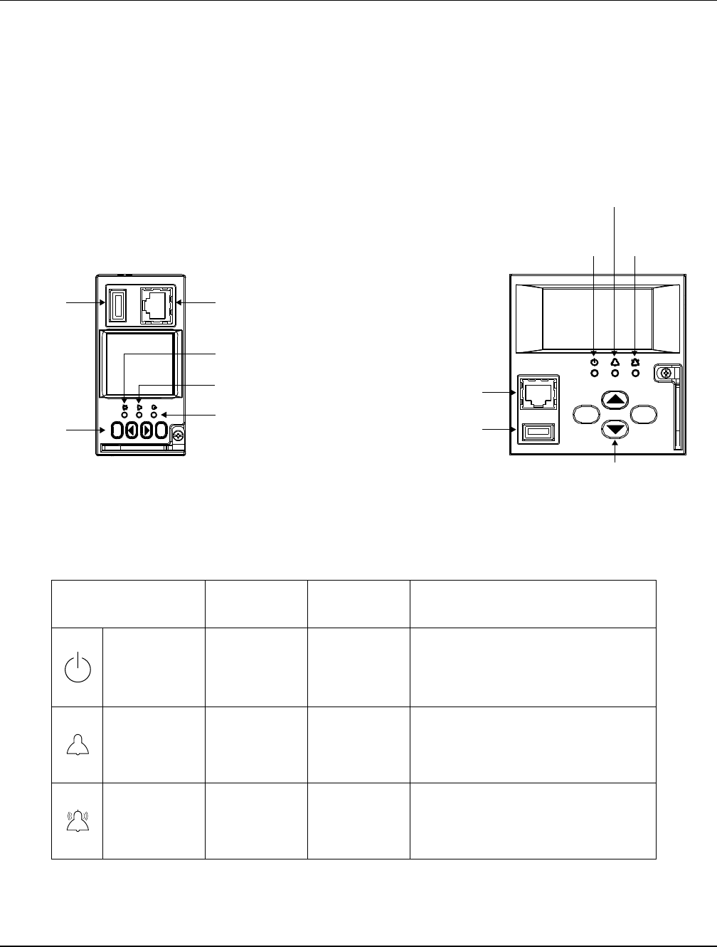
2.1 Local Indicators
Location and Identification: Refer to Figure 7.
Description: There are three (3) indicators located on the ACU+ Controller’s front panel. Refer to Table 2
for the function of the indicators.
Figure 7
Local Indicators and Menu Navigation Keys Locations
Indicator
Normal State
Fault State
Fault Cause
Status
(Green)
On
Off
No input power to the ACU+
Controller.
Minor
Alarm
(Yellow)
Off
On
The system has one or more active
Minor alarms. Alarm conditions are
programmable.
Critical/Major
Alarm (Red)
Off
On
The system has one or more active
Critical or Major alarms. Alarm
conditions are programmable.
Table 2
Local Indicators
ESC
ENT
USB
Port 10/100M Ethernet
Port (RJ-45)
M820B
Critical or Major
Alarm Indicator
(Red)
Minor Alarm
Indicator (Yellow)
Status
Indicator
(Green)
Menu
Navigation
Keys
Status
Indicator
(Green)
Minor Alarm
Indicator (Yellow)
Critical or Major
Alarm Indicator
(Red)
ESC ENT
Menu Navigation Keys
USB
Port
10/100M Ethernet
Port (RJ-45)
M820D

User Instructions UM1M820BNA
Spec No. 1M820BNA (Model M820B) Issue AH, March 4, 2013
Spec No. 1M820DNA (Model M820D)
Chapter 2. Operation 17
This document is property of Emerson Network Power, Energy Systems, North America, Inc. and contains confidential and proprietary information owned by Emerson Network Power, Energy
Systems, North America, Inc. Any copying, use, or disclosure of it without the written permission of Emerson Network Power, Energy Systems, North America, Inc. is strictly prohibited.
2.2 Passwords and Access Levels
Users (for local and Web access to the ACU+ Controller) are set via the Web Interface.
Note that anyone can browse the ACU+ via the local keypad and display. A password is required to
change settings. Web access always requires a User Name and password to be entered to gain
access.
Users are configured with a User Name, password, and access level.
User Name: Maximum 13 Characters (0-9, a-z, A-Z, _ ).
Password: Maximum 13 Characters (0-9, a-z, A-Z, _ ).
Once a password is entered, it remains in effect for a preset time period to allow navigating between
menus without re-entering the password.
Access Level: Refer to the following table.
A User has access to his/her level menus, plus all menus of the lesser access levels.
Access Level
(Authority Level)
Default User Name
and Password
Authority
Level A (Browser)
none set
The User can only read (browse) information in the
menus.
Level B (Operator)
none set
The User has access to the system "Control" menus.
Level C (Engineer)
none set
The User has access to the system "Setting" menus
and can download the configuration file.
Level D (Administrator)
Admin, 1
The User has full access to all menus; including update
the OS application and modifying, adding, and deleting
Users.

UM1M820BNA User Instructions
Issue AH, March 4, 2013 Spec No. 1M820BNA (Model M820B)
Spec No. 1M820DNA (Model M820D)
18 Chapter 2. Operation
This document is property of Emerson Network Power, Energy Systems, North America, Inc. and contains confidential and proprietary information owned by Emerson Network Power, Energy
Systems, North America, Inc. Any copying, use, or disclosure of it without the written permission of Emerson Network Power, Energy Systems, North America, Inc. is strictly prohibited.
2.3 Local Keypad and Display Access
2.3.1 Local Menu Navigation Keys and LCD Display
Location and Identification: Refer to Figure 7.
Description: There are four (4) menu navigation keys and an LCD display located on the ACU+
Controller’s front panel. Refer to Table 3 for the function of the menu navigation keys.
Note: When the LCD is lit, if no button is pushed for 8 minutes, the backlight of the LCD display
extinguishes and the ACU+ Controller returns to the Main Screen. Press any key to re-activate the
LCD display.
Key Symbol
Key Name
Function
ESC
Escape
Press this key to go back to a
previous menu or to cancel setting
a parameter.
Press ESC and ENT together to
reset the ACU+ Controller, then
press ENT to accept or ESC to
cancel.
ENT
Enter
Press this key to go forward to the
next menu, to select a parameter
to edit, or to validate a parameter
setting change.
Up
Press or to scroll through
the menus or to change the value
of a parameter.
--
Down
Press any key to silence an audible alarm.
Table 3
Local Menu Navigation Keys
2.3.2 Local Display Menus
Refer to “Chapter 3. Local Display Menus”.
Note: A valid password is required to access menus that allow changing any power system parameter.
Navigating the Menus
To Select a Sub-Menu:
Press the up or down arrow keys to move the cursor up and down the list of sub-menus in the menu
screen (selects the sub-menu), then press ENT to enter the selected sub-menu.
To Enter a Password:
If a password screen opens, a password must be entered to allow the User to make adjustments. To enter
a password, with the cursor at the User Name field (default is “Admin”), press the down arrow key to move
cursor down to the password line. Press ENT. “0” is highlighted. Press the up arrow key once to change
the “0” to”1” (default password is “1”), then press ENT twice. (Note: If you have been assigned a unique
User Name and password, follow this procedure to enter these.)
To Change a Parameter:
Press the up or down arrow keys to move the cursor up and down the list of parameters in the menu
screen (selects the parameter to change), then press ENT to change the selected parameter. The
parameter field highlights. Press the up or down arrow keys to change the parameter value. Press ENT to
confirm the change.

User Instructions UM1M820BNA
Spec No. 1M820BNA (Model M820B) Issue AH, March 4, 2013
Spec No. 1M820DNA (Model M820D)
Chapter 2. Operation 19
This document is property of Emerson Network Power, Energy Systems, North America, Inc. and contains confidential and proprietary information owned by Emerson Network Power, Energy
Systems, North America, Inc. Any copying, use, or disclosure of it without the written permission of Emerson Network Power, Energy Systems, North America, Inc. is strictly prohibited.
2.4 WEB Interface Access
Note: The ACU+ supports a 10/100M Ethernet connection.
2.4.1 Overview
Via the WEB Interface, a User (with proper access level) can:
View real-time operating information (rectifiers, converters, AC, DC, Batteries, etc.).
View and download information recorded in logs.
Send control commands.
Set programmable parameters.
Download and upload configuration files.
Download firmware to the Controller.
2.4.2 Setting IP Communications Parameters
The Controller’s IP parameters (IP, subnet mask, and gateway addresses) must be set to match your
company’s network settings. The default settings for these parameters are shown below.
IP Address: 192.168.1.2
Subnet Mask Address: 255.255.255.0
Gateway Address: 192.168.1.1
Local Menu Navigation: Main Menu / Settings / Communication / enter parameters.
WEB Menu Navigation: Maintenance / Network Configuration / enter parameters.
2.4.3 WEB Interface Menus
Refer to “Chapter 4. WEB Interface Menus”.
2.4.4 Connecting the Controller Locally (via the Ethernet Port)
Before connecting your computer directly to the Controller’s Ethernet Port, record your current network
settings as outlined below, then change these settings to match the communications settings
programmed into the Controller.
Procedure
1) Record your computer’s network settings by launching Control Panel in your computer. Navigate
through Network Connections
Local Area Connection
Properties
Internet Protocol
(TCP/IP)
Properties.
2) Record whether the "Obtain an IP address automatically" or "Use the following IP address" button
is selected. If "Use the following IP address" button is selected, also record the following:
IP Address:
Subnet Mask:
Default Gateway:
3) Record your Controller’s network settings by navigating the Controller’s local display panel to Main
Menu
Settings
Communication.
4) Record the following information:
IP Address:
Subnet Mask:
Default Gateway:
Example:
IP Address: 192.168.1.2

UM1M820BNA User Instructions
Issue AH, March 4, 2013 Spec No. 1M820BNA (Model M820B)
Spec No. 1M820DNA (Model M820D)
20 Chapter 2. Operation
This document is property of Emerson Network Power, Energy Systems, North America, Inc. and contains confidential and proprietary information owned by Emerson Network Power, Energy
Systems, North America, Inc. Any copying, use, or disclosure of it without the written permission of Emerson Network Power, Energy Systems, North America, Inc. is strictly prohibited.
Subnet Mask: 255.255.255.0
Default Gateway: 192.168.1.1
5) Change your local computer’s network settings using the information you acquired in Step 4),
except that the last part of the IP address needs to be replaced with any different number.
IP Address:
Subnet Mask:
Default Gateway:
Example:
IP Address: 192.168.1.3
Subnet Mask: 255.255.255.0
Default Gateway: 192.168.1.1
6) Select OK. Note that you may have to reboot your local computer for the settings to take effect.
Follow any instruction you see on the screen.
2.4.5 Disabling Proxy Server Settings to Enable a Connection
to the Controller over an Intranet Network (if required)
Note: This procedure needs to be performed only when the Controller is connected to an Intranet and the
User’s computer is set to access the Intranet through a proxy server. Note that if the Controller is
connected to the Internet and the User’s computer is connected to an Intranet, the User may not
be able to disable the proxy server and access the Controller.
If the Controller’s Ethernet Port is connected to your company’s Intranet Network and your computer is
also connected to the Intranet Network but requires access via a proxy server, you must disable the proxy
server settings to access the Controller. Follow the procedure below to disable the proxy server settings.
Procedure
1) Launch “Internet Explorer”.
2) Select Internet Options from the Tools menu. The “Internet Options” window opens. In the
“Internet Options” window, select the Connections Tab.
3) Click on the LAN Settings... button. The following window opens. In the LAN Settings window,
uncheck the Proxy Server box and click OK.

User Instructions UM1M820BNA
Spec No. 1M820BNA (Model M820B) Issue AH, March 4, 2013
Spec No. 1M820DNA (Model M820D)
Chapter 2. Operation 21
This document is property of Emerson Network Power, Energy Systems, North America, Inc. and contains confidential and proprietary information owned by Emerson Network Power, Energy
Systems, North America, Inc. Any copying, use, or disclosure of it without the written permission of Emerson Network Power, Energy Systems, North America, Inc. is strictly prohibited.
2.4.6 Logging into the Controller
Procedure
1) Internet Explorer, version 5.5 or newer, is required. It is best to view the WEB Interface at
1280 x 1024 resolution. In newer versions of Internet Explorer, you may need to turn Compatibility
View On (Tools Menu / Compatibility View).
2) In Internet Explorer, enter the IP address programmed into the Controller and press ENTER. The
following WEB Interface window opens. Enter a valid User Name and Password then click LOGIN.
Note: By default, the “User Name” is "admin" and the “Password” is “1”.
3) After entering a valid User Name and Password and clicking LOGIN, the "HOMEPAGE" window
opens. Refer to “Chapter 4. WEB Interface Menus”.

UM1M820BNA User Instructions
Issue AH, March 4, 2013 Spec No. 1M820BNA (Model M820B)
Spec No. 1M820DNA (Model M820D)
22 Chapter 2. Operation
This document is property of Emerson Network Power, Energy Systems, North America, Inc. and contains confidential and proprietary information owned by Emerson Network Power, Energy
Systems, North America, Inc. Any copying, use, or disclosure of it without the written permission of Emerson Network Power, Energy Systems, North America, Inc. is strictly prohibited.
2.5 Common Tasks Performed via the Local Keypad and/or Web Interface
Refer also to “Chapter 3. Local Display Menus” and “Chapter 4. WEB Interface Menus”.
2.5.1 Backing Up the Configuration
A file named “SettingParam.run” is automatically created/appended by the Controller whenever a User
makes changes to any parameter settings via the LCD or WEB interface. This file can be saved to your
computer so you can restore any custom settings you may have made.
Prior to changing settings, ensure the current “SettingParam.run” file is backed up. After making changes,
create a new backup file. Note that you may change the name of a “SettingParam.run” file to differentiate
it from other files saved. The new name can use alpha and numeric characters preceding the original
“SettingParam.run” name (the end of the new file name must always be “SettingParam.run”; for example,
an acceptable filename would be “seville4SettingParam.run”).
Local Menu Navigation: none.
WEB Menu Navigation: See also “4.7.9. Retrieve ‘SettingParam.run’ File Sub-Menu”.
1) Log onto the Controller using the WEB Interface.
2) Click on “Retrieve SettingParam.run” in the MAINTENANCE MENU.
3) Click on the “Retrieve File” button to save the file named "SettingParam.run" to you hard drive.
Note: Ensure Internet Explorer security settings are set to enable a file to be downloaded.
4) Select where you want the file to be copied to on your computer.
2.5.2 Reloading a Backed-Up Configuration
Reload the ACU+ configuration by restoring the “SettingParam.run” file previously saved. Refer to “2.5.1
Backing Up the Configuration” for a procedure to save the “SettingParam.run” file.
Local Menu Navigation: none.
WEB Menu Navigation: See also “4.7.8 Download Sub-Menu”.
1) Log onto the Controller using the WEB Interface.
2) Click on “Download” in the MAINTENANCE MENU.
3) The "Stop Controller" window opens. Click on the “Stop Controller” button.
4) A Download window opens.
Warning: Never navigate from this web page without first clicking on "Start Controller". If
you do, you will not have web access. A manual system reset is required to
restore web access.
5) Click the “Browse….” button and navigate to the folder where the file is located. Select the file and
then click the “Download” button. Click “Start Controller” to restart the Controller with the
downloaded file installed.
2.5.3 Reloading the Configuration File Stored in the ACU+ Controller
Note: When this procedure is performed, the “SettingParam.run” file (see 2.5.1) is deleted.
Local Menu Navigation: Main Menu / Settings / Controller / Reload Config.
The only selection for "Reload Config" is Yes. Once Yes is selected and confirmed, the configuration file
stored in the ACU+ Controller is reloaded into memory. All settings WILL BE restored to the factory
defaults of the configuration file.
WEB Menu Navigation: Maintenance / Restore Factory Defaults / select “Restore Defaults”.

User Instructions UM1M820BNA
Spec No. 1M820BNA (Model M820B) Issue AH, March 4, 2013
Spec No. 1M820DNA (Model M820D)
Chapter 2. Operation 23
This document is property of Emerson Network Power, Energy Systems, North America, Inc. and contains confidential and proprietary information owned by Emerson Network Power, Energy
Systems, North America, Inc. Any copying, use, or disclosure of it without the written permission of Emerson Network Power, Energy Systems, North America, Inc. is strictly prohibited.
2.5.4 Downloading a Configuration or an Application ("All") Package into the ACU+
Controller
The name of the Configuration or Application "All" Package file must end in .tar or .tar.gz. An Application
“All” package file has both the application (software) and configuration files and is usually supplied for an
application upgrade.
Local Menu Navigation: A User can copy a Configuration or an Application ("All") Package from your
computer to a USB memory device. You can then place the USB memory device into the ACU+ USB port
and then download the file into the ACU+ Controller.
To Download a Configuration Locally:
1) Copy the file to a USB memory device. The file must be in the root directory of the USB memory
device. The file must be named app_cfg.tar or app_cfg.tar.gz.
2) Connect the USB memory device to the USB port on the front of the Controller.
3) Navigate to Main Menu / Settings / Controller / Download Config.
4) The only selection for "Download Config" is Yes. Once Yes is selected and confirmed, the
configuration file located on the memory device located in the Controller’s USB port is loaded into
the Controller.
5) After the file is downloaded, remove the memory device from the Controller’s USB port.
6) Return to the Main Screen, then reboot the Controller (press ENT and ESC at the same time).
7) The screen displays "System Is Rebooting" then "App Exited".
8) The Controller enters an initialization routine, which takes a few minutes. The routine is complete
and the Controller is operational when normal system voltage is displayed on the screen.
To Download an Application ("All") Package Locally:
1) Copy the file to a USB memory device. The file must be in the root directory of the USB memory
device. The file must be named app.tar.gz.
2) Connect the USB memory device to the USB port on the front of the Controller.
3) With the Controller displaying the Main Screen, reboot the Controller (press ENT and ESC at the
same time).
4) The screen displays "Acknowledge Info. Reboot System."
5) Press ENT to confirm.
6) The screen displays…
"System Is Rebooting"
"App Exited"
then the Emerson Network Power logo appears followed by…
“Press the key ENT to Download the Application."
7) Press ENT.
8) The screen displays "Please Wait".
9) The Controller enters an initialization routine, which takes a few minutes. The routine is complete
and the Controller is operational when normal system voltage is displayed on the screen.
10) Remove the memory device.
WEB Menu Navigation: See also “4.7.8 Download Sub-Menu”.
1) Log onto the Controller using the WEB Interface.
2) Click on “Download” in the MAINTENANCE MENU.

UM1M820BNA User Instructions
Issue AH, March 4, 2013 Spec No. 1M820BNA (Model M820B)
Spec No. 1M820DNA (Model M820D)
24 Chapter 2. Operation
This document is property of Emerson Network Power, Energy Systems, North America, Inc. and contains confidential and proprietary information owned by Emerson Network Power, Energy
Systems, North America, Inc. Any copying, use, or disclosure of it without the written permission of Emerson Network Power, Energy Systems, North America, Inc. is strictly prohibited.
3) The "Stop Controller" window opens. Click on the “Stop Controller” button.
4) A Download window opens.
Warning: Never navigate from this web page without first clicking on "Start Controller". If
you do, you will not have web access. A manual system reset is required to
restore web access.
5) Click the “Browse….” button and navigate to the folder where the file is located. Select the file and
then click the “Download” button. Click “Start Controller” to restart the Controller with the
downloaded file installed.
2.5.5 Rebooting the Controller
Local Menu Navigation: Press ENT and ESC at the same time to reset the ACU+ Controller.
WEB Menu Navigation: Maintenance / Restore Factory Defaults / select “Reboot Controller”.
2.5.6 Changing the Local LCD Display Contrast
Local Menu Navigation: Press ENT and UP ARROW or ENT and DOWN ARROW while in the Main
Screen to change the contrast of the LCD display.
WEB Menu Navigation: none.
2.5.7 Disabling the Local Keypad Sound
Local Menu Navigation: Main Menu / Settings / Controller / Keypad Voice.
To disable the keypad sound, set "Keypad Voice" to "Off".
WEB Menu Navigation: none.
2.5.8 Changing the Date
Local Menu Navigation: Main Menu / Settings / Controller / Date.
After selecting Date (by pressing ENT when the cursor is in the Date field), use and to select the year
then press ENT, next use and to select the month then press ENT, and finally use and to select
the day then press ENT.
WEB Menu Navigation: Maintenance / Time Sync.
2.5.9 Changing the Time
Local Menu Navigation: Main Menu / Settings / Controller / Time.
After selecting Time (by pressing ENT when the cursor is in the Time field), use and to select the
hour then press ENT, next use and to select the minute then press ENT, and finally use and to
select the second then press ENT.
WEB Menu Navigation: Maintenance / Time Sync.
2.5.10 Adding, Deleting, and Modifying Users
Local Menu Navigation: none.
WEB Menu Navigation: Refer to “4.7.5 User Information Settings Sub-Menu”.
2.5.11 Assigning Severity Level to Alarms
Local Menu Navigation: Main Menu / Settings / Alarm Setting / Alm Severity.
WEB Menu Navigation: Configuration / Signal Information Modification / select entry from “Query Device
Type” list / select “Alarm Signal” from “Signal Type” list / select entry from “New Level” list / press “Set”.

User Instructions UM1M820BNA
Spec No. 1M820BNA (Model M820B) Issue AH, March 4, 2013
Spec No. 1M820DNA (Model M820D)
Chapter 2. Operation 25
This document is property of Emerson Network Power, Energy Systems, North America, Inc. and contains confidential and proprietary information owned by Emerson Network Power, Energy
Systems, North America, Inc. Any copying, use, or disclosure of it without the written permission of Emerson Network Power, Energy Systems, North America, Inc. is strictly prohibited.
2.5.12 Assigning Relays to Alarms
Local Menu Navigation: Main Menu / Settings / Alarm Setting / Alarm Relay.
WEB Menu Navigation: Configuration / Alarm Relays / select entry from “Standard Equipment” list /
select entry from “New Relay Number” list / press “Modify”.
2.5.13 Changing the Names of Items Displayed in the LCD and Web-Interface Menus
Note: Only relay names and digital input names are recommended to be changed for troubleshooting
purposes.
Local Menu Navigation: none.
WEB Menu Navigation: Configuration / Equipment Information Modification.
Configuration / Signal Information Modification.
2.5.14 Viewing Alarms
Local Menu Navigation: Main Menu / Status / Active Alarms.
WEB Menu Navigation: Active alarms are listed in the lower right window pane. If the window pane is
collapsed, click the "arrow" icon to expand the alarm list.
2.5.15 Clearing Rectifier Lost, Rectifier Communication Fail, Converter Lost, Converter
Communication Fail, and All Converter Comm Fail Alarms
Navigate to the menus to clear the respective alarm as indicated below.
Local Menu Navigation: Main Menu / Manual / Rectifier / All Rect Ctrl.
Main Menu / Manual / Converter / All Conv Ctrl.
WEB Menu Navigation: Device Information / Rectifier Group / Control Tab.
Device Information / Converter Group / Control Tab.
2.5.16 Clearing SMTemp Lost and SMTemp Probe Alarms
Navigate to the menus to clear the respective alarm as indicated below.
Local Menu Navigation: Main Menu / Manual / SMTemp / SMTemp Group.
Main Menu / Manual / SMTemp / SMTemp #.
WEB Menu Navigation: Device Information / SM Temp Group / Control Tab.
Device Information / SM Temp Group / SM Temp # / Control Tab.
2.5.17 Clearing Battery Alarms
Navigate to the menus to clear the respective alarm as indicated below.
Local Menu Navigation: Main Menu / Manual / Batt Group.
WEB Menu Navigation: Device Information / Battery Group / Control Tab.
2.5.18 Clearing Logs
Local Menu Navigation: Main Menu / Settings / Alarm Setting / Alarm Param / Clr Alm Hist.
The only selection for "Clr Alm Hist" is Yes. Once Yes is selected and confirmed, the alarm history log is
cleared.
WEB Menu Navigation: Maintenance / Clear Data.
Select which log to clear (“Alarm History”, “Data History”, “Control Command Log”, “Battery Test Log”,
“System Runtime Log”, or “Diesel Test Log”). Select “Clear”.

UM1M820BNA User Instructions
Issue AH, March 4, 2013 Spec No. 1M820BNA (Model M820B)
Spec No. 1M820DNA (Model M820D)
26 Chapter 2. Operation
This document is property of Emerson Network Power, Energy Systems, North America, Inc. and contains confidential and proprietary information owned by Emerson Network Power, Energy
Systems, North America, Inc. Any copying, use, or disclosure of it without the written permission of Emerson Network Power, Energy Systems, North America, Inc. is strictly prohibited.
2.5.19 Clearing the Maintenance Alarm
A maintenance time can be set which, once expires, issues a maintenance alarm. When the maintenance
alarm is issued, perform the routine maintenance and reset the maintenance timer. To reset the
maintenance timer and clear the Maintenance Alarm, clear the Maintenance Run Time.
Local Menu Navigation: Place Controller in Manual Mode, then Main Menu / Manual / Power System /
Clr MtncRunTime.
The only selection for "Clr MtncRunTime" is Yes. Once Yes is selected and confirmed, the maintenance
timer is reset and the maintenance alarm is cleared.
Place Controller back to Auto mode.
WEB Menu Navigation: Quick Settings / “Auto/Manual” Setting / change to Manual.
then
Device Information / Power System / select the Control Tab and
clear the maintenance timer.
then
Quick Settings / “Auto/Manual” Setting / change to Auto.
2.5.20 Viewing the ACU+ Controller’s Device Inventory
Local Menu Navigation: Main Menu / Status / Sys Inventory.
WEB Menu Navigation: Maintenance / System Inventory.
2.5.21 Updating the ACU+ Controller’s Device Inventory
Local Menu Navigation: Main Menu / Settings / Controller / Auto Config.
The only selection for "Auto Config" is Yes. Once Yes is selected and confirmed, the ACU+ Controller will
auto-configure for the devices connected to it.
WEB Menu Navigation: Configuration / Auto Configuration.
2.5.22 Programming the Audible Alarm Feature
Local Menu Navigation: Main Menu / Settings / Alarm Setting / Alarm Param / Alarm Voice.
Set "Alarm Voice" to:
On: When a new alarm occurs, the audible alarm sounds. Press any key to silence the audible alarm.
Off: Disables the audible alarm.
3 minutes / 10 minutes / 1 hour / 4 hours: When a new alarm occurs, the audible alarm sounds.
The audible alarm automatically silences after the selected time period.
WEB Menu Navigation: none.
2.5.23 Blocking Alarms
Local Menu Navigation: Main Menu / Settings / Alarm Setting / Alarm Param / Block Alarm.
or
Local Menu Navigation: Main Menu / Settings / Power System / General / Alarm Blocked.
WEB Menu Navigation: Device Information / Power System / Settings Tab / Outgoing Alarms Blocked.
Set to:
Normal: Alarms are processed normally.
Blocked: Forces the alarm relays in the "off" state and blocks alarms from changing the relay state.

User Instructions UM1M820BNA
Spec No. 1M820BNA (Model M820B) Issue AH, March 4, 2013
Spec No. 1M820DNA (Model M820D)
Chapter 2. Operation 27
This document is property of Emerson Network Power, Energy Systems, North America, Inc. and contains confidential and proprietary information owned by Emerson Network Power, Energy
Systems, North America, Inc. Any copying, use, or disclosure of it without the written permission of Emerson Network Power, Energy Systems, North America, Inc. is strictly prohibited.
2.5.24 Configuring the ACU+ Identification of Rectifiers and
Assigning which Input Phase is Connected to the Rectifiers
When rectifiers are all installed prior to applying power and starting the system, the order in which the
ACU+ identifies the rectifiers is by serial number (lowest serial number is Rect 1, next lowest is Rect 2,
etc.). If you prefer the ACU+ to identify the rectifiers by position in the system, perform the following
procedure.
Upon power up, the ACU+ arbitrarily assigns Phase A, B, or C to each rectifier. This assignment is used to
display rectifier AC input phase voltage(s). The User may reassign the phase to each rectifier per your
specific installation by following the procedure below.
Local Menu Navigation: Main Menu / Settings / Rectifier / Rect #1 / Rectifier ID and Rect Phase.
(repeat for every rectifier)
then
Main Menu / Manual / Rectifier / All Rect Ctrl / Confirm ID/PH.
WEB Menu Navigation: Device Information / Rectifier Group / Rectifier #1 / Settings Tab / Rectifier ID
and Rectifier Phase.
(repeat for every rectifier)
then
Device Information / Rectifier Group / Control Tab / Confirm Rectifier
“ID/Phase”.
Local Procedure
1) With the Main screen displayed, press ENT to go to the Main Menu. Navigate to and select
“Settings” (ENT).
2) If a password screen opens, a password must be entered to allow the User to make adjustments. If
a password was previously entered and has not yet timed out, skip this step and proceed to step 3).
Otherwise, to enter a password, with the cursor at the User Name field (default is “Admin”), press
the down arrow key to move cursor down to the password line. Press ENT. “0” is highlighted.
Press the up arrow key once to change the “0” to”1” (default password is “1”), then press ENT twice.
(Note: If you have been assigned a unique User Name and password, follow this procedure to
enter these.)
3) With the Settings menu screen displayed, navigate to and select “Rectifier” (ENT).
4) Navigate to “Rect #” (# is used here to represent the rectifier identification number). Press ENT.
The rectifier # menu screen is displayed, and the green LED on one rectifier starts flashing. This is
the rectifier currently identified by the ACU+ as rectifier #. (If this is not the rectifier you want, press
ESC to return to rectifier menu screen and select a different rectifier.)
5) If you wish to change the Rectifier IDs, navigate to and select “Rectifier ID”. Press ENT. Use the
up or down keys to change the ACU+ identification number for the flashing rectifier. Press ENT.
6) If you wish to change the Rectifier Phase Assignment, navigate to and select “Rect Phase”. Press
ENT. Use the up or down keys to change the phase connected to the flashing rectifier. Press ENT.
7) Press ESC to return to rectifier menu screen.
8) Navigate to and select the next rectifier.
9) Repeat steps 4) through 8) for each of the remaining rectifiers in the system.
10) When you have finished selecting identification numbers and phases for all rectifiers, repeatedly
press ESC to return to the Main Menu.
11) Navigate to and select “Manual” (ENT) / “Rectifier” (ENT) / “All Rect Ctrl” (ENT).
12) Navigate to “Confirm ID/PH”. Press ENT. “Yes” highlights.

UM1M820BNA User Instructions
Issue AH, March 4, 2013 Spec No. 1M820BNA (Model M820B)
Spec No. 1M820DNA (Model M820D)
28 Chapter 2. Operation
This document is property of Emerson Network Power, Energy Systems, North America, Inc. and contains confidential and proprietary information owned by Emerson Network Power, Energy
Systems, North America, Inc. Any copying, use, or disclosure of it without the written permission of Emerson Network Power, Energy Systems, North America, Inc. is strictly prohibited.
13) Press ENT to select the operation. Press ENT again to confirm.
Note: Check you numbering to be sure it is correct. If there were conflicts in your numbering, rectifiers
with conflicts will be assigned the next available sequential number.
14) Return to the Main screen by repeatedly pressing ESC (escape).
2.5.25 Configuring the ACU+ Identification of Converters
When converters are all installed prior to applying power and starting the system, the order in which the
ACU+ identifies the converters is by serial number (lowest serial number is Conv 1, next lowest is Conv 2,
etc.).
If you prefer the ACU+ to identify the converters by position in the system, perform the following
procedure.
Local Menu Navigation: Main Menu / Settings / Converter / Conv #1 / Set Conv ID.
(repeat for every converter)
then
Main Menu / Manual / Converter / All Conv Ctrl / Confirm ID.
WEB Menu Navigation: Device Information / Converter Group / Converter #1 / Settings Tab /
Set Converter ID.
(repeat for every converter)
then
Device Information / Converter Group / Control Tab / Confirm Converters ID.
Local Procedure
1) With the Main screen displayed, press ENT to go to the Main Menu. Navigate to and select
“Settings” (ENT).
2) If a password screen opens, a password must be entered to allow the User to make adjustments. If
a password was previously entered and has not yet timed out, skip this step and proceed to step 3).
Otherwise, to enter a password, with the cursor at the User Name field (default is “Admin”), press
the down arrow key to move cursor down to the password line. Press ENT. “0” is highlighted.
Press the up arrow key once to change the “0” to”1” (default password is “1”), then press ENT twice.
(Note: If you have been assigned a unique User Name and password, follow this procedure to
enter these.)
3) With the Settings menu screen displayed, navigate to and select “Converter” (ENT).
4) Navigate to “Conv #” (# is used here to represent the converter identification number). Press ENT.
The converter # menu screen is displayed, and the green LED on one converter starts flashing.
This is the converter currently identified by the ACU+ as converter #. (If this is not the converter you
want, press ESC to return to converter menu screen and select a different converter.)
5) Navigate to and select “Set Conv ID”. Press ENT. Use the up or down keys to change the ACU+
identification number for the flashing converter. Press ENT.
6) Press ESC to return to converter menu screen.
7) Navigate to and select the next converter.
8) Repeat steps 4) through 7) for each of the remaining converters in the system.
9) When you have finished selecting identification numbers for all converters, repeatedly press ESC
to return to the Main Menu.
10) Navigate to and select “Manual” (ENT) / “Converter” (ENT) / “All Conv Ctrl” (ENT).
11) Navigate to “Confirm ID”. Press ENT. “Yes” highlights.
12) Press ENT to select the operation. Press ENT again to confirm.

User Instructions UM1M820BNA
Spec No. 1M820BNA (Model M820B) Issue AH, March 4, 2013
Spec No. 1M820DNA (Model M820D)
Chapter 2. Operation 29
This document is property of Emerson Network Power, Energy Systems, North America, Inc. and contains confidential and proprietary information owned by Emerson Network Power, Energy
Systems, North America, Inc. Any copying, use, or disclosure of it without the written permission of Emerson Network Power, Energy Systems, North America, Inc. is strictly prohibited.
Note: Check you numbering to be sure it is correct. If there where conflicts in your numbering,
converters with conflicts will be assigned the next available sequential number.
13) Return to the Main screen by repeatedly pressing ESC (escape).
2.5.26 Viewing/Changing the Float Voltage Setting
Local Menu Navigation: Main Menu / Settings / Battery / Charge / Float Voltage.
Local Menu Navigation: Main Menu / Quick Setting / “FLT/EQ” Voltag / Float Voltage.
WEB Menu Navigation: Device Information / Battery Group / Settings Tab / Float Charge Voltage.
WEB Menu Navigation: Quick Settings / “Float/Equalize” Charge Voltage.
2.5.27 Viewing/Changing the Equalize Voltage Setting
Local Menu Navigation: Main Menu / Settings / Battery / Charge / EQ Voltage.
Local Menu Navigation: Main Menu / Quick Setting / “FLT/EQ” Voltag / EQ Voltage.
WEB Menu Navigation: Device Information / Battery Group / Settings Tab / Equalize Charge Voltage.
WEB Menu Navigation: Quick Settings / “Float/Equalize” Charge Voltage.
2.5.28 Setting Digital Inputs
Local Menu Navigation: Main Menu / Settings / Power System / General / DI[number] Alarm State.
WEB Menu Navigation: Device Information / Power System / Settings Tab / DI[number] Alarm State.
2.5.29 Setting Temperature Sensors
Temperature sensors may be connected to the…
Temp1 and Temp2 ports on an IB2 Interface Board,
Temp1 and Temp2 ports on an EIB Interface Board, and
Temp1 through Temp8 ports of up to eight (8) SM-Temp modules.
Each port (sensor) may be set as None, Battery, or Ambient.
A temperature sensor set as an ambient temperature sensor may also be set as the sensor which displays
the ambient temperature on the Web Interface’s Homepage.
A temperature sensor set as a battery temperature sensor may also be set as the temperature
compensation sensor (in addition, the temperature compensation sensor is the sensor which displays the
battery temperature on the Web Interface’s Homepage).
A temperature sensor set as a battery temperature sensor may also be set as the BTRM (Battery Thermal
Runaway Management) sensor (in addition, the BTRM sensor is the sensor which is used for the High
Temperature Disconnect [HTD] Feature.)
First, set each temperature sensor in the system to None, Battery, or Ambient.
Local Menu Navigation: Main Menu / Settings / Power System / General / IB2 Temp#.
Main Menu / Settings / Power System / General / EIB Temp#.
Main Menu / Settings / SMTemp / SMTemp # / T# Assign Equip.
WEB Menu Navigation: Device Information / Power System / Settings Tab / IB2 Temp #.
Device Information / Power System / Settings Tab / EIB Temp #.
Device Information / SM Temp Group / SM Temp # / Settings Tab /
Temperature# Assign Equipment.

UM1M820BNA User Instructions
Issue AH, March 4, 2013 Spec No. 1M820BNA (Model M820B)
Spec No. 1M820DNA (Model M820D)
30 Chapter 2. Operation
This document is property of Emerson Network Power, Energy Systems, North America, Inc. and contains confidential and proprietary information owned by Emerson Network Power, Energy
Systems, North America, Inc. Any copying, use, or disclosure of it without the written permission of Emerson Network Power, Energy Systems, North America, Inc. is strictly prohibited.
Note: Also set High2, High1, and Low temperature alarms for each temperature sensor (from the
Web Interface). Note that you cannot set high and low temperature alarms for individual
temperature sensors from the Local Menus. High and low temperature alarm settings for the
temperature sensors set as ambient are found in the Device Information / Power System /
Settings tab. High and low temperature alarm settings for the probes set as battery are found
in the Device Information / Battery Group / Settings tab.
Second, if desired, set a temperature sensor set as an ambient temperature sensor as the sensor
which displays the ambient temperature on the Web Interface’s Homepage. Then set High2, High1,
and Low ambient temperature alarms (from the same menu).
Local Menu Navigation: Main Menu / Settings / Power System / Amb Temp Sensor.
WEB Menu Navigation: Device Information / Power System / Settings Tab / Ambient Temp Sensor.
Third, if desired, set a temperature sensor set as a battery temperature sensor as the battery
temperature compensation sensor. Then set High2, High1, and Low compensation temperature
alarms (from the same menu).
Local Menu Navigation: Main Menu / Settings / Battery / Temp Comp / TempComp Sensor.
WEB Menu Navigation: Device Information / Battery Group / Settings Tab / Temp Compensation
Probe Number.
Fourth, if desired, set a temperature sensor set as a battery temperature sensor as the BTRM sensor.
Then set High2 and High1 BTRM temperature alarms (from the same menu). If battery temperature
exceeds the “BTRM Temp High2” setting, system voltage is lowered to the BTRM voltage setting (set
from the same menu). Note, you must first enable this feature (from the same menu).
Local Menu Navigation: Main Menu / Settings / Battery / Basic / BTRM TempSensor.
WEB Menu Navigation: Device Information / Battery Group / Settings Tab / BTRM Temp Sensor.
2.5.30 Setting Battery Charge Temperature Compensation
The following need to be set for the Battery Charge Temperature Compensation feature.
See above for selecting the battery temperature compensation temperature sensor; or select maximum,
average, or Average SMBRC.
Local Menu Navigation: Main Menu / Settings / Battery / Temp Comp.
Enter values for the following parameters: Temp CompCenter, Temp Comp Coeff, TempComp
Sensor, Comp Temp High2, Comp Temp High1, Comp Temp Low, Temp Comp Max V, Temp Comp
Clamp, and Temp Comp Min V (note that you have to enable Temp Comp Clamp to set the Temp
Comp Max V and Min V values).
WEB Menu Navigation: Quick Settings / Temp Compensation Setting.
Enter values for the following parameters: Temperature Compensation Center, Temp Comp
Coefficient (slope), Temp Compensation Probe Number, Comp Temp High2, Comp Temp High1,
Comp Temp Low, Temp Comp Voltage Clamp, Temp Comp Max Voltage, and Temp Comp Min
Voltage (note that you have to enable Temp Comp Clamp to set the Temp Comp Max V and Min V
values).
2.5.31 Setting Auto Equalize
Local Menu Navigation: Main Menu / Settings / Battery / Charge / Auto EQ / once enabled, additional
parameters appear.
Local Menu Navigation: Main Menu / Settings / Battery / Charge / Cyc EQ / once enabled, additional
parameters appear.
Local Menu Navigation: Main Menu / Quick Setting / “FLT/EQ” Set.

User Instructions UM1M820BNA
Spec No. 1M820BNA (Model M820B) Issue AH, March 4, 2013
Spec No. 1M820DNA (Model M820D)
Chapter 2. Operation 31
This document is property of Emerson Network Power, Energy Systems, North America, Inc. and contains confidential and proprietary information owned by Emerson Network Power, Energy
Systems, North America, Inc. Any copying, use, or disclosure of it without the written permission of Emerson Network Power, Energy Systems, North America, Inc. is strictly prohibited.
Also set “Maximum EQ Time” in same menu.
WEB Menu Navigation: Device Information / Battery Group / Settings Tab / Automatic Equalize.
Once Automatic Equalize is enabled, additional parameters appear.
WEB Menu Navigation: Device Information / Battery Group / Settings Tab / Cyclic Equalize.
Once Cyclic Equalize is enabled, additional parameters appear.
WEB Menu Navigation: Quick Settings / “Float/Equalize” Settings / once Automatic Equalize and/or
Cyclic Equalize is enabled, additional parameters appear.
Also set “Maximum Equalize Charge Time” in same menu.
2.5.32 Setting Battery Parameters
Local Menu Navigation: Main Menu / Settings / Battery / Battery # / enter parameters.
WEB Menu Navigation: Device Information / Battery Group / Battery # / select the Settings Tab and enter
parameters.
2.5.33 Setting Battery Capacity Parameters
Local Menu Navigation: Main Menu / Settings / Battery / Battery # / Rated Capacity.
WEB Menu Navigation: Device Information / Battery Group / Battery # / select the Settings Tab and enter
the Battery Rating parameter.
2.5.34 Setting Battery Block and Battery Midpoint Monitoring (if equipped with an EIB
Assembly)
Local Menu Navigation: Main Menu / Settings / EIB / EIB 1 / enter the following parameters.
WEB Menu Navigation: Device Information / EIB Group / EIB 1 / select the Settings Tab and enter the
following parameters.
Parameters
Voltage Type
Blk V Diff(12V) or Blk V Diff(Mid)
Block In-Use
2.5.35 Setting IP Communications Parameters
Local Menu Navigation: Main Menu / Settings / Communication / enter parameters.
WEB Menu Navigation: Maintenance / Network Configuration / enter parameters.
2.5.36 Setting External Shunts (connected to the EIB Assembly)
Local Menu Navigation: Main Menu / Settings / EIB / EIB1 / enter the following parameters.
WEB Menu Navigation: Device Information / EIB Group / EIB 1 / select the Settings Tab and enter the
following parameters.
Parameters
Shunt # Current
Shunt # Voltage
Num Batt Shunts
Num Load Shunts
2.5.37 Setting External Shunts (connected to the SM-DU+ Assembly)
Local Menu Navigation: none.
WEB Menu Navigation: Device Information / SMDUP Group / SMDUP 1 / select the Settings Tab and
enter the following parameters.

UM1M820BNA User Instructions
Issue AH, March 4, 2013 Spec No. 1M820BNA (Model M820B)
Spec No. 1M820DNA (Model M820D)
32 Chapter 2. Operation
This document is property of Emerson Network Power, Energy Systems, North America, Inc. and contains confidential and proprietary information owned by Emerson Network Power, Energy
Systems, North America, Inc. Any copying, use, or disclosure of it without the written permission of Emerson Network Power, Energy Systems, North America, Inc. is strictly prohibited.
Parameters
Current1 Break Value (A) (Device rating.)
Current1 High Current Limit (% of Current# Break Value.)
Current1 Very High Current Limit (% of Current# Break Value.)
Shunt # Current (Rating of Shunt.)
Shunt # Voltage (Rating of Shunt.)
2.5.38 Setting the Load Current Alarm
Local Menu Navigation: Main Menu / Settings / Power System / General / Load Curr Alarm.
WEB Menu Navigation: Device Information / Power System / Settings Tab / Load Current Alarm.
Enter a value (in AMPS). If load current exceeds this value, a load current alarm is issued.
2.5.39 Placing the System in Float or Equalize Charge Mode
Local Menu Navigation: Main Menu / Manual / Batt Group / “EQ/FLT Control”.
WEB Menu Navigation: Device Information / Battery Group / Control Tab / “Equalize/Float” Charge
Control.
2.5.40 Manually Forcing Relays
See also “2.5.42 Using the Relay Test Feature”.
Place Controller in Manual Mode, then...
Local Menu Navigation: Main Menu / Manual / Power System / Relay Output [number].
Main Menu / Manual / EIB / EIB1 / Relay Output [number].
Select the other state for an alarm relay (active / not active).
After confirming the change, the alarm relay will momentarily toggle to the chosen state. The alarm
relay then reverts back to being controlled by the ACU+.
WEB Menu Navigation: Device Information / Power System / Control Tab.
Device Information / EIB Group / EIB1 / Control Tab.
The Control Tab allows you to change the state of an alarm relay.
In the "Set value" box, select the other state for an alarm relay (active / not active).
Click on "set".
After confirming the change, the alarm relay will momentarily toggle to the chosen state. The alarm
relay then reverts back to being controlled by the ACU+.
2.5.41 Manually Forcing LVDs
Place Controller in Manual Mode, then...
Local Menu Navigation: Main Menu / Manual / LVD / LVD Unit.
Select the other state for an LVD (connected/disconnected).
After confirming the change, the LVD will momentarily toggle to the chosen state. The LVD then
reverts back to being controlled by the ACU+.
WEB Menu Navigation: Device Information / LVD Group / LVD Unit / select the Control Tab.
The Control Tab allows you to change the state of an LVD.
In the "Set value" box, select the other state for an LVD (connected/disconnected).
Click on "set".

User Instructions UM1M820BNA
Spec No. 1M820BNA (Model M820B) Issue AH, March 4, 2013
Spec No. 1M820DNA (Model M820D)
Chapter 2. Operation 33
This document is property of Emerson Network Power, Energy Systems, North America, Inc. and contains confidential and proprietary information owned by Emerson Network Power, Energy
Systems, North America, Inc. Any copying, use, or disclosure of it without the written permission of Emerson Network Power, Energy Systems, North America, Inc. is strictly prohibited.
After confirming the change, the LVD will momentarily toggle to the chosen state. The LVD then
reverts back to being controlled by the ACU+.
2.5.42 Using the Relay Test Feature
Note: The relay test can only be performed when no alarms are present.
Automatic Test
When placed in Relay Automatic Test Mode, all relays on the IB2 board deenergize (when set for Fail
Safe), then one-by-one each relay energizes for the time period selected and then deenergizes. If the
system is equipped with an EIB board, after the IB2 relays are tested, one-by-one each relay on the EIB
board deenergizes for the time period selected and then re-energizes. At the end of the test, all relays are
returned to their normal state (if no alarms are present).
Local Menu Navigation: Main Menu / Settings / Power System / General / set the Relay Test Time.
then
Main Menu / Settings / Power System / General / Relay Test / set to Automatic.
Note: The relay test can be exited at any time by setting the Relay Test to Disabled.
WEB Menu Navigation: Device Information / Power System / Settings Tab / set the Relay Test Time.
then
Device Information / Power System / Settings Tab / Relay Test /
set to Automatic.
Note: The relay test can be exited at any time by setting the Relay Test to Disabled.
Individual Test
When placed in Relay Individual Test Mode, relays can be tested individually. This is the same procedure
as “2.5.40 Manually Forcing Relays” except you do not place the Controller in Manual Mode.
Local Menu Navigation: Main Menu / Settings / Power System / General / Relay Test / set to Individual.
then
Main Menu / Manual / Power System / Relay Output [number]
(individually you can set the state of the relays on the IB2 Board).
Main Menu / Manual / EIB / EIB1 / Relay Output [number]
(individually you can set the state of the relays on the EIB Board).
Select the other state for an alarm relay (active / not active).
After confirming the change, the alarm relay will momentarily toggle to the chosen state. The alarm
relay then reverts back to being controlled by the ACU+.
When done, set “Relay Test” to “Disabled”. Note that if there is no User interaction for 10 minutes, the
Relay Test will automatically revert to the “disabled” state.
WEB Menu Navigation: Device Information / Power System / Settings Tab / Relay Test /
set to Individual.
then
Device Information / Power System / Control Tab.
(individually you can set the state of the relays on the IB2 Board).
Device Information / EIB Group / EIB 1 / Control Tab
(individually you can set the state of the relays on the EIB Board).
The Control Tab allows you to change the state of an alarm relay.
In the "Set value" box, select the other state for an alarm relay (active / not active).
Click on "set".
After confirming the change, the alarm relay will momentarily toggle to the chosen state. The alarm
relay then reverts back to being controlled by the ACU+.

UM1M820BNA User Instructions
Issue AH, March 4, 2013 Spec No. 1M820BNA (Model M820B)
Spec No. 1M820DNA (Model M820D)
34 Chapter 2. Operation
This document is property of Emerson Network Power, Energy Systems, North America, Inc. and contains confidential and proprietary information owned by Emerson Network Power, Energy
Systems, North America, Inc. Any copying, use, or disclosure of it without the written permission of Emerson Network Power, Energy Systems, North America, Inc. is strictly prohibited.
When done, set “Relay Test” to “Disabled”.
2.5.43 Spec. No. 588820300 Battery Rack System (Lithium Ion Battery Configuration)
When the ACU+ is equipped with the Lithium Ion Battery Configuration for use with Spec. No. 588820300
NetSure™ Battery Rack System, the only required settings for battery functions is the float voltage and
ABCL (Active Battery Charge Current Limit) point.
Note: The maximum value that the ABCL point can be adjusted to is 60A, which is below the maximum
current the battery can handle.
The batteries communicate their status and alarms to the ACU+. The ACU+ displays these via the LCD
and WEB interfaces.
Batteries are added to the ACU+ inventory as they are detected. If a battery communications cable is
removed, a Li-Ion Battery Communication Fail alarm is generated. If the controller resets while a Li-Ion
Battery Communication Fail alarm is active, the alarm changes to a Li-Ion Battery Lost alarm. If you clear
any of these alarms, that battery is removed from the ACU+ inventory.

User Instructions UM1M820BNA
Spec No. 1M820BNA (Model M820B) Issue AH, March 4, 2013
Spec No. 1M820DNA (Model M820D)
Chapter 2. Operation 35
This document is property of Emerson Network Power, Energy Systems, North America, Inc. and contains confidential and proprietary information owned by Emerson Network Power, Energy
Systems, North America, Inc. Any copying, use, or disclosure of it without the written permission of Emerson Network Power, Energy Systems, North America, Inc. is strictly prohibited.
2.6 Available Alarms
Table 4 lists the alarms that you can scroll through in the Alarm Severity and Alarm Relay submenus.
These are also the possible alarms that display in the Active Alarms sub-menu. Table 4 also provides
guidelines for alarm correction.
Note: These instructions describe the complete functionality of the ACU+. Some functionality is
dependent on hardware connected to the ACU+. Some alarms listed may not display in your
system or may be named differently. Refer to the ACU+ Configuration Drawing (C-drawing)
furnished with your system.
Table 4
Full Alarm Name - WEB
(Abbreviated
Alarm Name - LCD)
Alarm Description
Action to Correct
Power System Alarms
(Power System)
Supervision Unit Fault
(SelfDetect Fail)
Controller self detection test fails.
Replace the Controller.
CAN Communication Failure
(CAN Comm Fail)
CAN bus communications failure.
Check communications cables.
Outgoing Alarms Blocked
(Alarm Blocked)
Alarm relays are forced in the "off"
state and alarms are blocked from
changing the relay state.
Verify why Controller setting was
changed before changing back.
Maintenance Time Limit
Alarm
(Mtnc Time Alarm)
Controller issues a maintenance
alarm.
Perform routine maintenance and
reset maintenance timer.
“Config Error
(Backup Config)”
(Config Error 1)
Configuration error 1.
Reload configuration file.
“Config Error
(Default Config)”
(Config Error 2)
Configuration error 2.
Imbalance System Current
(Imbalance Curr)
Current sharing imbalance.
Check to see why current sharing is
imbalanced.
Over Load
(Over Load)
Output overload condition.
Check to see why output is
overloaded.
SPD
(SPD)
Surge protection device needs
attention.
Check surge protection device.
EStop/EShutdown
(EStop/EShutdown)
System in emergency stop or
emergency shutdown mode.
Check to see why the system was
placed in this mode.

UM1M820BNA User Instructions
Issue AH, March 4, 2013 Spec No. 1M820BNA (Model M820B)
Spec No. 1M820DNA (Model M820D)
36 Chapter 2. Operation
This document is property of Emerson Network Power, Energy Systems, North America, Inc. and contains confidential and proprietary information owned by Emerson Network Power, Energy
Systems, North America, Inc. Any copying, use, or disclosure of it without the written permission of Emerson Network Power, Energy Systems, North America, Inc. is strictly prohibited.
Table 4
Full Alarm Name - WEB
(Abbreviated
Alarm Name - LCD)
Alarm Description
Action to Correct
System Temp1 Not Used
(System T1 Not U)
Temperature sensor port #1 is not
used.
(Note: This alarm is not used at this
time.)
System Temp2 Not Used
(System T2 Not U)
Temperature sensor port #2 is not
used.
System Temp3 Not Used
(System T3 Not U)
Temperature sensor port #3 is not
used.
IB2 Temp1 Not Used
(IB2 T1 Not Used)
Temperature sensor port #1 (on IB2
Board) is empty.
--
IB2 Temp2 Not Used
(IB2 T2 Not Used)
Temperature sensor port #2 (on IB2
Board) is empty.
EIB Temp1 Not Used
(EIB T1 Not Used)
Temperature sensor port #1 (on EIB
Board) is empty.
--
EIB Temp2 Not Used
(EIB T2 Not Used)
Temperature sensor port #2 (on EIB
Board) is empty.
System Temp1
Sensor Fault
(System T1 Senso)
Temperature sensor #1 failure.
(Note: This alarm is not used at this
time.)
System Temp2
Sensor Fault
(System T2 Senso)
Temperature sensor #2 failure.
System Temp3
Sensor Fault
(System T3 Senso)
Temperature sensor #3 failure.
IB2 Temp1 Sensor Fault
(IB2 T1 Sensor F)
Temperature sensor #1 (connected to
IB2 Board) failure.
Replace temperature sensor.
IB2 Temp2 Sensor Fault
(IB2 T2 Sensor F)
Temperature sensor #2 (connected to
IB2 Board) failure.
EIB Temp1 Sensor Fault
(EIB T1 Sensor F)
Temperature sensor #1 (connected to
EIB Board) failure.
Replace temperature sensor.
EIB Temp2 Sensor Fault
(EIB T2 Sensor F)
Temperature sensor #2 (connected to
EIB Board) failure.
DHCP Failure
(DHCP Failure)
The DHCP function is enabled, but
effective IP address cannot be
acquired.
Verify DHCP IP address.
PLC Config Error
(PLC Config Err)
PLC configuration error.
Re-enter the PLC logic functions.

User Instructions UM1M820BNA
Spec No. 1M820BNA (Model M820B) Issue AH, March 4, 2013
Spec No. 1M820DNA (Model M820D)
Chapter 2. Operation 37
This document is property of Emerson Network Power, Energy Systems, North America, Inc. and contains confidential and proprietary information owned by Emerson Network Power, Energy
Systems, North America, Inc. Any copying, use, or disclosure of it without the written permission of Emerson Network Power, Energy Systems, North America, Inc. is strictly prohibited.
Table 4
Full Alarm Name - WEB
(Abbreviated
Alarm Name - LCD)
Alarm Description
Action to Correct
485 Communication Failure
(485 Comm Fail)
485 communications failure.
--
Minor Summary
(MN Summary)
Minor alarm summary (one or more
alarms designated as minor is active).
Check additional alarms.
Major Summary
(MJ Summary)
Major alarm summary (one or more
alarms designated as major is active).
Check additional alarms.
Critical Summary
(CR Summary)
Critical alarm summary (one or more
alarms designated as critical is active).
Check additional alarms.
Rectifier Group Lost
(Rect Group Lost)
A rectifier group cannot be detected by
the Controller.
Check communications cables.
Check additional alarms.
Over Voltage 1
(Over Voltage 1)
Output voltage is higher than the Over
Voltage 1 Alarm threshold.
Check to see why system voltage is
high. Check the alarm setting.
Over Voltage 2
(Over Voltage 2)
Output voltage is higher than the Over
Voltage 2 Alarm threshold.
Under Voltage 1
(Under Voltage 1)
Output voltage is lower than the Under
Voltage 1 Alarm threshold.
Check to see why system voltage is
low. If there is a mains failure, check if
some load could be switched off in
order to prolong the operating time of
the plant. If the system load is too high
related to rectifier capacity, install
additional rectifiers. If the batteries are
being recharged, the alarm will cease
by itself when battery voltage has
increased to the charging level.
Under Voltage 2
(Under Voltage 2)
Output voltage is lower than the Under
Voltage 2 Alarm threshold.
Over Voltage 1 (24V)
(24V Over Volt1)
Output voltage is higher than the Over
Voltage 1 Alarm threshold.
Check to see why system voltage is
high. Check the alarm setting.
Over Voltage 2 (24V)
(24V Over Volt2)
Output voltage is higher than the Over
Voltage 2 Alarm threshold.

UM1M820BNA User Instructions
Issue AH, March 4, 2013 Spec No. 1M820BNA (Model M820B)
Spec No. 1M820DNA (Model M820D)
38 Chapter 2. Operation
This document is property of Emerson Network Power, Energy Systems, North America, Inc. and contains confidential and proprietary information owned by Emerson Network Power, Energy
Systems, North America, Inc. Any copying, use, or disclosure of it without the written permission of Emerson Network Power, Energy Systems, North America, Inc. is strictly prohibited.
Table 4
Full Alarm Name - WEB
(Abbreviated
Alarm Name - LCD)
Alarm Description
Action to Correct
Under Voltage 1 (24V)
(24V Under Volt1)
Output voltage is lower than the Under
Voltage 1 Alarm threshold.
Check to see why system voltage is
low. If there is a mains failure, check if
some load could be switched off in
order to prolong the operating time of
the plant. If the system load is too high
related to rectifier capacity, install
additional rectifiers. If the batteries are
being recharged, the alarm will cease
by itself when battery voltage has
increased to the charging level.
Under Voltage 2 (24V)
(24V Under Volt2)
Output voltage is lower than the Under
Voltage 2 Alarm threshold.
Diesel Run Over Temp
(DG Run OverTemp)
Diesel generator run over temperature
alarm.
Check diesel generator.
DG1 is Running
(DG1 is Running)
Diesel generator 1 is running.
--
DG2 is Running
(DG2 is Running)
Diesel generator 2 is running.
--
Hybrid is High Load
(High Load)
Diesel generator high load alarm.
Check load on diesel generator.
DG1 Failure
(DG1 Failure)
Diesel generator 1 has failed.
Check diesel generator.
DG2 Failure
(DG2 Failure)
Diesel generator 2 has failed.
Check diesel generator.
Grid is on
(Grid is on)
AC is on grid.
--
Ambient Temp High 1
(Amb Temp High1)
High diesel generator ambient
temperature alarm1.
Check why temperature is high or low.
Ambient Temp Low
(Amb Temp Low)
Low diesel generator ambient
temperature alarm.
Ambient Temp High 2
(Amb Temp High2)
High diesel generator ambient
temperature alarm2.
Ambient Sensor Fault
(AmbSensor Fault)
Diesel generator temperature sensor
failure.
Replace temperature sensor.

User Instructions UM1M820BNA
Spec No. 1M820BNA (Model M820B) Issue AH, March 4, 2013
Spec No. 1M820DNA (Model M820D)
Chapter 2. Operation 39
This document is property of Emerson Network Power, Energy Systems, North America, Inc. and contains confidential and proprietary information owned by Emerson Network Power, Energy
Systems, North America, Inc. Any copying, use, or disclosure of it without the written permission of Emerson Network Power, Energy Systems, North America, Inc. is strictly prohibited.
Table 4
Full Alarm Name - WEB
(Abbreviated
Alarm Name - LCD)
Alarm Description
Action to Correct
DI1Alarm
(DI1 Alarm)
Digital input #1 alarm is active.
Check why alarm is active.
…
…
DI7Alarm
(DI7 Alarm)
Digital input #7 alarm is active.
DI8 ESTOP
(DI8 ESTOP)
Digital input #8 alarm is active.
IB Communication Fail
(IB Comm Fail)
ACU+ Interface Board
communications failure.
Check communications cables.
Relay Testing
(Relay Testing)
Relay Test in progress.
--
Testing Relay 1
(Testing Relay 1)
Testing Relay 1 (on IB2 Board).
--
…
…
Testing Relay 8
(Testing Relay 8)
Testing Relay 8 (on IB2 Board).
System Temp1 High 2
(System T1 Hi2)
Temperature sensor #1 sensing
temperature higher than high
temperature threshold 2.
Note: This alarm is not used at this
time.)
System Temp1 High 1
(System T1 Hi1)
Temperature sensor #1 sensing
temperature higher than high
temperature threshold 1.
System Temp1 Low
(System T1 Low)
Temperature sensor #1 sensing
temperature lower than low
temperature threshold.
System Temp2 High 2
(System T2 Hi2)
Temperature sensor #2 sensing
temperature higher than high
temperature threshold 2.
Note: This alarm is not used at this
time.)
System Temp2 High 1
(System T2 Hi1)
Temperature sensor #2 sensing
temperature higher than high
temperature threshold 1.
System Temp2 Low
(System T2 Low)
Temperature sensor #2 sensing
temperature lower than low
temperature threshold.

UM1M820BNA User Instructions
Issue AH, March 4, 2013 Spec No. 1M820BNA (Model M820B)
Spec No. 1M820DNA (Model M820D)
40 Chapter 2. Operation
This document is property of Emerson Network Power, Energy Systems, North America, Inc. and contains confidential and proprietary information owned by Emerson Network Power, Energy
Systems, North America, Inc. Any copying, use, or disclosure of it without the written permission of Emerson Network Power, Energy Systems, North America, Inc. is strictly prohibited.
Table 4
Full Alarm Name - WEB
(Abbreviated
Alarm Name - LCD)
Alarm Description
Action to Correct
System Temp3 High 2
(System T3 Hi2)
Temperature sensor #3 sensing
temperature higher than high
temperature threshold 2.
Note: This alarm is not used at this
time.)
System Temp3 High 1
(System T3 Hi1)
Temperature sensor #3 sensing
temperature higher than high
temperature threshold 1.
System Temp3 Low
(System 31 Low)
Temperature sensor #3 sensing
temperature lower than low
temperature threshold.
IB2 Temp1 High 2
(IB2 T1 Hi2)
Temperature sensor #1 (connected to
IB2 board and set as Ambient)
sensing temperature higher than high
temperature threshold 2.
Check why temperature is high or low.
IB2 Temp1 High 1
(IB2 T1 Hi1)
Temperature sensor #1 (connected to
IB2 board and set as Ambient)
sensing temperature higher than high
temperature threshold 1.
IB2 Temp1 Low
(IB2 T1 Low)
Temperature sensor #1 (connected to
IB2 board and set as Ambient)
sensing temperature lower than low
temperature threshold.
IB2 Temp2 High 2
(IB2 T2 Hi2)
Temperature sensor #2 (connected to
IB2 board and set as Ambient)
sensing temperature higher than high
temperature threshold 2.
Check why temperature is high or low.
IB2 Temp2 High 1
(IB2 T2 Hi1)
Temperature sensor #2 (connected to
IB2 board and set as Ambient)
sensing temperature higher than high
temperature threshold 1.
IB2 Temp2 Low
(IB2 T2 Low)
Temperature sensor #2 (connected to
IB2 board and set as Ambient)
sensing temperature lower than low
temperature threshold.

User Instructions UM1M820BNA
Spec No. 1M820BNA (Model M820B) Issue AH, March 4, 2013
Spec No. 1M820DNA (Model M820D)
Chapter 2. Operation 41
This document is property of Emerson Network Power, Energy Systems, North America, Inc. and contains confidential and proprietary information owned by Emerson Network Power, Energy
Systems, North America, Inc. Any copying, use, or disclosure of it without the written permission of Emerson Network Power, Energy Systems, North America, Inc. is strictly prohibited.
Table 4
Full Alarm Name - WEB
(Abbreviated
Alarm Name - LCD)
Alarm Description
Action to Correct
EIB Temp1 High 2
(EIB T1 Hi2)
Temperature sensor #1 (connected to
EIB board and set as Ambient)
sensing temperature higher than high
temperature threshold 2.
Check why temperature is high or low.
EIB Temp1 High 1
(EIB T1 Hi1)
Temperature sensor #1 (connected to
EIB board and set as Ambient)
sensing temperature higher than high
temperature threshold 1.
EIB Temp1 Low
(EIB T1 Low)
Temperature sensor #1 (connected to
EIB board and set as Ambient)
sensing temperature lower than low
temperature threshold.
EIB Temp2 High 2
(EIB T2 Hi2)
Temperature sensor #2 (connected to
EIB board and set as Ambient)
sensing temperature higher than high
temperature threshold 2.
Check why temperature is high or low.
EIB Temp2 High 1
(EIB T2 Hi1)
Temperature sensor #2 (connected to
EIB board and set as Ambient)
sensing temperature higher than high
temperature threshold 1.
EIB Temp2 Low
(EIB T2 Low)
Temperature sensor #2 (connected to
EIB board and set as Ambient)
sensing temperature lower than low
temperature threshold.
SMTemp1 Temp1 High 2
(SMTemp1 T1 Hi2)
Temperature sensor #1 (connected to
SM-Temp 1 and set as Ambient)
sensing temperature higher than high
temperature threshold 2.
Check why temperature is high or low.
SMTemp1 Temp1 High 1
(SMTemp1 T1 Hi1)
Temperature sensor #1 (connected to
SM-Temp 1 and set as Ambient)
sensing temperature higher than high
temperature threshold 1.
SMTemp1 Temp1 Low
(SMTemp1 T1 Low)
Temperature sensor #1 (connected to
SM-Temp 1 and set as Ambient)
sensing temperature lower than low
temperature threshold.
…
…
…

UM1M820BNA User Instructions
Issue AH, March 4, 2013 Spec No. 1M820BNA (Model M820B)
Spec No. 1M820DNA (Model M820D)
42 Chapter 2. Operation
This document is property of Emerson Network Power, Energy Systems, North America, Inc. and contains confidential and proprietary information owned by Emerson Network Power, Energy
Systems, North America, Inc. Any copying, use, or disclosure of it without the written permission of Emerson Network Power, Energy Systems, North America, Inc. is strictly prohibited.
Table 4
Full Alarm Name - WEB
(Abbreviated
Alarm Name - LCD)
Alarm Description
Action to Correct
SMTemp1 Temp8 High 2
(SMTemp1 T8 Hi2)
Temperature sensor #8 (connected to
SM-Temp 1 and set as Ambient)
sensing temperature higher than high
temperature threshold 2.
Check why temperature is high or low.
SMTemp1 Temp8 High 1
(SMTemp1 T8 Hi1)
Temperature sensor #8 (connected to
SM-Temp 1 and set as Ambient)
sensing temperature higher than high
temperature threshold 1.
SMTemp1 Temp8 Low
(SMTemp1 T8 Low)
Temperature sensor #8 (connected to
SM-Temp 1 and set as Ambient)
sensing temperature lower than low
temperature threshold.
…
…
…
SMTemp8 Temp1 High 2
(SMTemp8 T1 Hi2)
Temperature sensor #1 (connected to
SM-Temp 8 and set as Ambient)
sensing temperature higher than high
temperature threshold 2.
Check why temperature is high or low.
SMTemp8 Temp1 High 1
(SMTemp8 T1 Hi1)
Temperature sensor #1 (connected to
SM-Temp 8 and set as Ambient)
sensing temperature higher than high
temperature threshold 1.
SMTemp8 Temp1 Low
(SMTemp8 T1 Low)
Temperature sensor #1 (connected to
SM-Temp 8 and set as Ambient)
sensing temperature lower than low
temperature threshold.
…
…
…
SMTemp8 Temp8 High 2
(SMTemp8 T8 Hi2)
Temperature sensor #8 (connected to
SM-Temp 8 and set as Ambient)
sensing temperature higher than high
temperature threshold 2.
Check why temperature is high or low.
SMTemp8 Temp8 High 1
(SMTemp8 T8 Hi1)
Temperature sensor #8 (connected to
SM-Temp 8 and set as Ambient)
sensing temperature higher than high
temperature threshold 1.
SMTemp8 Temp8 Low
(SMTemp8 T8 Low)
Temperature sensor #8 (connected to
SM-Temp 8 and set as Ambient)
sensing temperature lower than low
temperature threshold.

User Instructions UM1M820BNA
Spec No. 1M820BNA (Model M820B) Issue AH, March 4, 2013
Spec No. 1M820DNA (Model M820D)
Chapter 2. Operation 43
This document is property of Emerson Network Power, Energy Systems, North America, Inc. and contains confidential and proprietary information owned by Emerson Network Power, Energy
Systems, North America, Inc. Any copying, use, or disclosure of it without the written permission of Emerson Network Power, Energy Systems, North America, Inc. is strictly prohibited.
Table 4
Full Alarm Name - WEB
(Abbreviated
Alarm Name - LCD)
Alarm Description
Action to Correct
High Load Level1
(HighLoadLevel1)
Load current above high level 1.
Check to see why load current is high.
High Load Level2
(HighLoadLevel2)
Load current above high level 2.
Load Current Alarm
(Load Curr Alarm)
Load current alarm active.
Check to see why load current alarm is
active.
Rectifier Group Alarms
(Rect Group)
Multiple Rectifiers Failure
(Multi-Rect Fail)
More than one rectifier has failed.
Check input voltage to rectifiers.
Replace rectifiers.
Rectifier Lost
(Rectifier Lost)
A rectifier cannot be detected by the
Controller.
Reset the Rectifier Lost alarm.
Replace defective rectifier.
ECO Active
(ECO Active)
Rectifier Energy Optimization Mode is
enabled.
Check to see why system was placed
into this mode.
All Rectifiers Comm Fail
(AllRectCommFail)
No response from all rectifiers.
Check the connectors and cables or
the CAN loop. Replace the Controller.
ECO Cycle Alarm
(ECO Cycle Alarm)
If Energy Optimization Mode is
enabled and the Controller oscillates
in and out of Energy Optimization
more than 5 times, this alarm is
generated.
Check for other alarms.
Reset this alarm.
Rectifier Alarms
(Rectifier)
AC Input Failure
(AC Failure)
No AC input power to a rectifier.
Check why no AC input power
available.
Rect Temperature High
(Rect Temp High)
A rectifier has a high temperature
condition.
Check why temperature is high.
Rectifier Fault
(Rect Fault)
A rectifier has a fault condition.
Refer to Rectifier User Manual for
troubleshooting information.
HVSD
(HVSD)
A rectifier has an overvoltage
condition.
Rectifier Protected
(Rect Protected)
A rectifier is in protected mode.
Fan Failure
(Fan Failure)
A rectifier’s fan has failed.
Replace fan.

UM1M820BNA User Instructions
Issue AH, March 4, 2013 Spec No. 1M820BNA (Model M820B)
Spec No. 1M820DNA (Model M820D)
44 Chapter 2. Operation
This document is property of Emerson Network Power, Energy Systems, North America, Inc. and contains confidential and proprietary information owned by Emerson Network Power, Energy
Systems, North America, Inc. Any copying, use, or disclosure of it without the written permission of Emerson Network Power, Energy Systems, North America, Inc. is strictly prohibited.
Table 4
Full Alarm Name - WEB
(Abbreviated
Alarm Name - LCD)
Alarm Description
Action to Correct
Current Limit
(Current Limit)
A rectifier is in current limit.
Rectifier overload. The load is higher
than rectifier capacity. If the batteries
are being recharged, the alarm will
cease by itself when the battery
voltage has increased to the charging
level. If the system load is higher than
the rectifier capacity, the batteries will
discharge. If this is the reason, install
additional rectifiers. If one or more of
the rectifiers are defective, replace the
faulty rectifiers.
Rectifier Communication Fail
(Rect Comm Fail)
A rectifier has lost communications
with the Controller.
Check communications cables. Reset
the Communication Fail alarm.
Replace the rectifier.
Derated
(Derated)
A rectifier is in output power derating
mode.
Refer to Rectifier User Manual for
troubleshooting information.
Current Share Alarm
(Curr Share Alm)
A rectifier has a current sharing alarm.
AC Under Voltage Protection
(Low AC Protect)
A rectifier is in under voltage
protection mode.
Battery Group Alarms
(Battery Group)
Short Battery Test Running
(ShortBatTestRun)
Battery is in short time test mode.
--
Equalize for Test
(EQ for Test)
Battery is in equalize charge test
mode.
--
Manual Test
(Manual Test)
Battery is in manual battery discharge
test mode.
--
Planned Test
(Planned Test)
Battery is in planned battery test
mode.
--
AC Fail Test
(AC Fail Test)
AC power has been switched off to the
rectifiers to perform a battery
discharge test.
--
Manual Equalize
(Manual EQ)
Battery is in manual equalize charging
mode.
--
Automatic Equalize
(Auto EQ)
Battery is in automatic equalize
charging mode.
--
Cyclic Equalize
(Cyclic EQ)
Battery is in cyclic equalize charging
mode.
--

User Instructions UM1M820BNA
Spec No. 1M820BNA (Model M820B) Issue AH, March 4, 2013
Spec No. 1M820DNA (Model M820D)
Chapter 2. Operation 45
This document is property of Emerson Network Power, Energy Systems, North America, Inc. and contains confidential and proprietary information owned by Emerson Network Power, Energy
Systems, North America, Inc. Any copying, use, or disclosure of it without the written permission of Emerson Network Power, Energy Systems, North America, Inc. is strictly prohibited.
Table 4
Full Alarm Name - WEB
(Abbreviated
Alarm Name - LCD)
Alarm Description
Action to Correct
Master Equalize
(Master EQ)
In slave mode, the slave unit starts
equalize charging with the master unit.
--
Master Battery Test
(Master Bat Test)
In slave mode, the slave unit starts the
test with the master unit.
--
Discharge Current Imbalance
(Dsch Curr Imb)
Battery distribution current imbalance
alarm.
The currents from two groups of
batteries are not equal. Check the
batteries.
Abnormal Battery Current
(Abnl Batt Curr)
The equalize charging current
exceeds the alarm setting.
Check the alarm setting.
Temperature Compensation
Active
(TempComp Active)
Battery charge temperature
compensation is active.
--
Battery Current
Limit Active
(Batt Curr Limit)
Battery is in current limit.
--
Bad Battery
(Bad Battery)
Battery test fails.
Check the batteries.
Battery Discharge
(Battery Disch)
Battery is discharging.
A battery test is active (the discharge
test will stop automatically). There is a
mains failure (check that it is not
caused by open AC input circuit
breaker). The system load is higher
than rectifier capacity, causing the
batteries to discharge (install
additional rectifiers).
Battery Test Fail
(BatteryTestFail)
Battery test fails.
Check the batteries.
Comp Temp High2
(Comp Temp High2)
Compensation temperature sensor
sensing temperature higher than high
temperature threshold 2.
Check why temperature is high or low.
Comp Temp High1
(Comp Temp High1)
Compensation temperature sensor
sensing temperature higher than high
temperature threshold 1.
Comp Temp Low
(Comp Temp Low)
Compensation temperature sensor
sensing temperature lower than low
temperature threshold.
Compensation Sensor Fault
(CompTempFail)
Temperature Compensation
temperature sensor failure.
Replace temperature sensor.

UM1M820BNA User Instructions
Issue AH, March 4, 2013 Spec No. 1M820BNA (Model M820B)
Spec No. 1M820DNA (Model M820D)
46 Chapter 2. Operation
This document is property of Emerson Network Power, Energy Systems, North America, Inc. and contains confidential and proprietary information owned by Emerson Network Power, Energy
Systems, North America, Inc. Any copying, use, or disclosure of it without the written permission of Emerson Network Power, Energy Systems, North America, Inc. is strictly prohibited.
Table 4
Full Alarm Name - WEB
(Abbreviated
Alarm Name - LCD)
Alarm Description
Action to Correct
System Temp1 High 2
(System T1 Hi2)
Temperature sensor #1 sensing
temperature higher than high
temperature threshold 2.
Note: This alarm is not used at this
time.)
System Temp1 High 1
(System T1 Hi1)
Temperature sensor #1 sensing
temperature higher than high
temperature threshold 1.
System Temp1 Low
(System T1 Low)
Temperature sensor #1 sensing
temperature lower than low
temperature threshold.
System Temp2 High 2
(System T2 Hi2)
Temperature sensor #2 sensing
temperature higher than high
temperature threshold 2.
Note: This alarm is not used at this
time.)
System Temp2 High 1
(System T2 Hi1)
Temperature sensor #2 sensing
temperature higher than high
temperature threshold 1.
System Temp2 Low
(System T2 Low)
Temperature sensor #2 sensing
temperature lower than low
temperature threshold.
System Temp3 High 2
(System T3 Hi2)
Temperature sensor #3 sensing
temperature higher than high
temperature threshold 2.
Note: This alarm is not used at this
time.)
System Temp3 High 1
(System T3 Hi1)
Temperature sensor #3 sensing
temperature higher than high
temperature threshold 1.
System Temp3 Low
(System T3 Low)
Temperature sensor #3 sensing
temperature lower than low
temperature threshold.
IB2 Temp1 High 2
(IB2 T1 Hi2)
Temperature sensor #1 (connected to
IB2 board and set as Battery) sensing
temperature higher than high
temperature threshold 2.
Check why temperature is high or low.
IB2 Temp1 High 1
(IB2 T1 Hi1)
Temperature sensor #1 (connected to
IB2 board and set as Battery) sensing
temperature higher than high
temperature threshold 1.
IB2 Temp1 Low
(IB2 T1 Low)
Temperature sensor #1 (connected to
IB2 board and set as Battery) sensing
temperature lower than low
temperature threshold.

User Instructions UM1M820BNA
Spec No. 1M820BNA (Model M820B) Issue AH, March 4, 2013
Spec No. 1M820DNA (Model M820D)
Chapter 2. Operation 47
This document is property of Emerson Network Power, Energy Systems, North America, Inc. and contains confidential and proprietary information owned by Emerson Network Power, Energy
Systems, North America, Inc. Any copying, use, or disclosure of it without the written permission of Emerson Network Power, Energy Systems, North America, Inc. is strictly prohibited.
Table 4
Full Alarm Name - WEB
(Abbreviated
Alarm Name - LCD)
Alarm Description
Action to Correct
IB2 Temp2 High 2
(IB2 T2 Hi2)
Temperature sensor #2 (connected to
IB2 board and set as Battery) sensing
temperature higher than high
temperature threshold 2.
Check why temperature is high or low.
IB2 Temp2 High 1
(IB2 T2 Hi1)
Temperature sensor #2 (connected to
IB2 board and set as Battery) sensing
temperature higher than high
temperature threshold 1.
IB2 Temp2 Low
(IB2 T2 Low)
Temperature sensor #2 (connected to
IB2 board and set as Battery) sensing
temperature lower than low
temperature threshold.
EIB Temp1 High 2
(EIB T1 Hi2)
Temperature sensor #1 (connected to
EIB board and set as Battery) sensing
temperature higher than high
temperature threshold 2.
Check why temperature is high or low.
EIB Temp1 High 1
(EIB T1 Hi1)
Temperature sensor #1 (connected to
EIB board and set as Battery) sensing
temperature higher than high
temperature threshold 1.
EIB Temp1 Low
(EIB T1 Low)
Temperature sensor #1 (connected to
EIB board and set as Battery) sensing
temperature lower than low
temperature threshold.
EIB Temp2 High 2
(EIB T2 Hi2)
Temperature sensor #2 (connected to
EIB board and set as Battery) sensing
temperature higher than high
temperature threshold 2.
Check why temperature is high or low.
EIB Temp2 High 1
(EIB T2 Hi1)
Temperature sensor #2 (connected to
EIB board and set as Battery) sensing
temperature higher than high
temperature threshold 1.
EIB Temp2 Low
(EIB T2 Low)
Temperature sensor #2 (connected to
EIB board and set as Battery) sensing
temperature lower than low
temperature threshold.

UM1M820BNA User Instructions
Issue AH, March 4, 2013 Spec No. 1M820BNA (Model M820B)
Spec No. 1M820DNA (Model M820D)
48 Chapter 2. Operation
This document is property of Emerson Network Power, Energy Systems, North America, Inc. and contains confidential and proprietary information owned by Emerson Network Power, Energy
Systems, North America, Inc. Any copying, use, or disclosure of it without the written permission of Emerson Network Power, Energy Systems, North America, Inc. is strictly prohibited.
Table 4
Full Alarm Name - WEB
(Abbreviated
Alarm Name - LCD)
Alarm Description
Action to Correct
SMTemp1 Temp1 High 2
(SMTemp1 T1 Hi2)
Temperature sensor #1 (connected to
SM-Temp 1 and set as Battery)
sensing temperature higher than high
temperature threshold 2.
Check why temperature is high or low.
SMTemp1 Temp1 High 1
(SMTemp1 T1 Hi1)
Temperature sensor #1 (connected to
SM-Temp 1 and set as Battery)
sensing temperature higher than high
temperature threshold 1.
SMTemp1 Temp1 Low
(SMTemp1 T1 Low)
Temperature sensor #1 (connected to
SM-Temp 1 and set as Battery)
sensing temperature lower than low
temperature threshold.
…
…
…
SMTemp1 Temp8 High 2
(SMTemp1 T8 Hi2)
Temperature sensor #8 (connected to
SM-Temp 1 and set as Battery)
sensing temperature higher than high
temperature threshold 2.
Check why temperature is high or low.
SMTemp1 Temp8 High 1
(SMTemp1 T8 Hi1)
Temperature sensor #8 (connected to
SM-Temp 1 and set as Battery)
sensing temperature higher than high
temperature threshold 1.
SMTemp1 Temp8 Low
(SMTemp1 T8 Low)
Temperature sensor #8 (connected to
SM-Temp 1 and set as Battery)
sensing temperature lower than low
temperature threshold.
…
…
…
SMTemp8 Temp1 High 2
(SMTemp8 T1 Hi2)
Temperature sensor #1 (connected to
SM-Temp 8 and set as Battery)
sensing temperature higher than high
temperature threshold 2.
Check why temperature is high or low.
SMTemp8 Temp1 High 1
(SMTemp8 T1 Hi1)
Temperature sensor #1 (connected to
SM-Temp 8 and set as Battery)
sensing temperature higher than high
temperature threshold 1.
SMTemp8 Temp1 Low
(SMTemp8 T1 Low)
Temperature sensor #1 (connected to
SM-Temp 8 and set as Battery)
sensing temperature lower than low
temperature threshold.
…
…
…

User Instructions UM1M820BNA
Spec No. 1M820BNA (Model M820B) Issue AH, March 4, 2013
Spec No. 1M820DNA (Model M820D)
Chapter 2. Operation 49
This document is property of Emerson Network Power, Energy Systems, North America, Inc. and contains confidential and proprietary information owned by Emerson Network Power, Energy
Systems, North America, Inc. Any copying, use, or disclosure of it without the written permission of Emerson Network Power, Energy Systems, North America, Inc. is strictly prohibited.
Table 4
Full Alarm Name - WEB
(Abbreviated
Alarm Name - LCD)
Alarm Description
Action to Correct
SMTemp8 Temp8 High 2
(SMTemp8 T8 Hi2)
Temperature sensor #8 (connected to
SM-Temp 8 and set as Battery)
sensing temperature higher than high
temperature threshold 2.
Check why temperature is high or low.
SMTemp8 Temp8 High 1
(SMTemp8 T8 Hi1)
Temperature sensor #8 (connected to
SM-Temp 8 and set as Battery)
sensing temperature higher than high
temperature threshold 1.
SMTemp8 Temp8 Low
(SMTemp8 T8 Low)
Temperature sensor #8 (connected to
SM-Temp 8 and set as Battery)
sensing temperature lower than low
temperature threshold.
BTRM Temp High 2
(BTRM Temp High2)
Battery temperature (monitored by the
sensor set as BTRM) is higher than
the BTRM Temperature Alarm 2
threshold.
Check why temperature is high or low.
BTRM Temp High 1
(BTRM Temp High1)
Battery temperature (monitored by the
sensor set as BTRM) is higher than
the BTRM Temperature Alarm 1
threshold.
BTRM Sensor Fault
(BTRM TempFault)
BTRM temperature sensor failure.
Replace temperature sensor.
Li-Ion Battery Lost
(LiBatt Lost)
A Li-Ion Battery cannot be detected by
the Controller.
Check communications cables.
Clear the Li-Ion Battery Lost alarm.
1 Li-Ion Battery Disconnect
(1 LiBattDiscon)
One (1) Li-Ion Battery is disconnected.
Check why the Li-Ion Battery
disconnected.
2+Li-Ion Battery Disconnect
(2+LiBattDiscon)
Two (2) or more Li-Ion Batteries are
disconnected.
Check why the Li-Ion Batteries
disconnected.
1 Li-Ion Battery No Reply
(1 LiBattNoReply)
One (1) Li-Ion Battery has lost
communications with the Controller.
Check communications cables.
Clear the Li-Ion Communication Fail
alarm.
2+Li-Ion Battery No Reply
(2+LiBattNoReply)
Two (2) or more Li-Ion Batteries have
lost communications with the
Controller.
Check communications cables.
Clear the Li-Ion Communication Fail
alarm.
Inventory Update In Process
(InventUpdating)
Li-Ion Battery inventory being
updated.
--
ABCL is active
(ABCL Active)
Active Battery Charge Current Limit is
active.
--

UM1M820BNA User Instructions
Issue AH, March 4, 2013 Spec No. 1M820BNA (Model M820B)
Spec No. 1M820DNA (Model M820D)
50 Chapter 2. Operation
This document is property of Emerson Network Power, Energy Systems, North America, Inc. and contains confidential and proprietary information owned by Emerson Network Power, Energy
Systems, North America, Inc. Any copying, use, or disclosure of it without the written permission of Emerson Network Power, Energy Systems, North America, Inc. is strictly prohibited.
Table 4
Full Alarm Name - WEB
(Abbreviated
Alarm Name - LCD)
Alarm Description
Action to Correct
Battery Alarms
(Battery)
Battery Current Limit
Exceeded
(Ov Batt Cur Lmt)
Battery current limit point is exceeded.
--
Battery Over Current
(Batt Over Curr)
Battery is in over current.
--
Low Battery Capacity
(Low Batt Cap)
Battery has low capacity.
Check the batteries.
SMDU Battery Alarms (SM-DU Module must be present in system)
(SMDU Battery)
Exceed Current Limit
(Exceed Curr Lmt)
Battery current limit point is exceeded.
--
Over Battery Current
(Over Current)
Battery is in over current.
--
Low Capacity
(Low Capacity)
Battery has low capacity.
Check the batteries.
EIB (Extended Interface Board) Battery Alarms (EIB Board must be present in system)
(EIB Battery)
Battery Current Limit
Exceeded
(Ov Bat Curr Lmt)
Battery current limit point is exceeded.
--
Battery Over Current
(Bat Over Curr)
Battery is in over current.
--
Battery Low Capacity
(Low Batt Cap)
Battery has low capacity.
Check the batteries.
SM Battery Alarms (SM-BAT Module must be present in system)
(SM Battery)
Exceed Batt Current Limit
(Over Curr Limit)
Battery is in over current.
--
Over Battery Current
(Over Batt Curr)
Battery current is high.
--
Battery Leakage
(Battery Leakage)
Battery has leakage current.
Check the batteries.
Low Acid Level
(Low Acid Level)
Battery has low acid level.
Check the batteries.

User Instructions UM1M820BNA
Spec No. 1M820BNA (Model M820B) Issue AH, March 4, 2013
Spec No. 1M820DNA (Model M820D)
Chapter 2. Operation 51
This document is property of Emerson Network Power, Energy Systems, North America, Inc. and contains confidential and proprietary information owned by Emerson Network Power, Energy
Systems, North America, Inc. Any copying, use, or disclosure of it without the written permission of Emerson Network Power, Energy Systems, North America, Inc. is strictly prohibited.
Table 4
Full Alarm Name - WEB
(Abbreviated
Alarm Name - LCD)
Alarm Description
Action to Correct
Battery Disconnected
(Batt Disconnec)
Battery disconnection is active.
--
Battery High Temperature
(Batt High Temp)
Battery has high temperature
condition.
--
Battery Low Temperature
(Batt Low Temp)
Battery has low temperature condition.
--
Cell Voltage Difference
(Cell Volt Diff)
Battery cell voltage difference
detected.
Check the batteries.
SM Unit Fail
(SM Unit Fail)
Battery monitoring device has failed.
Replace device.
Battery Temperature Sensor
Fault
(T Sensor Fault)
Battery temperature sensor has failed.
Replace temperature sensor.
Low Capacity
(Low Capacity)
Battery has low capacity.
Check the batteries.
Battery Communication Fail
(Batt Comm Fail)
Battery monitoring device has lost
communications with the Controller.
Check communications cables.
Battery Temp not Used
(Bat Temp No Use)
No battery temperature sensor.
--
LargeDU Battery Alarms (Large Distribution Unit must be present in system)
(LargeDU Batt)
Battery Current Limit
Exceeded
(Ov Batt Cur Lmt)
Battery current limit point is exceeded.
--
Battery Low Capacity
(Batt Low Cap)
Battery has low capacity.
Check the batteries.
Battery Fuse Failure
(Batt Fuse Fail)
Battery fuse is open.
--
Battery Over Voltage
(Batt Over Volt)
Battery has over voltage condition.
--
Battery Under Voltage
(Batt Under Volt)
Battery has under voltage condition.
--
Battery Over Current
(Batt Over Curr)
Battery has over current condition.
--
Communication Fail
(Comm Fail)
Battery monitoring device has lost
communications with the Controller.
Check communications cables.

UM1M820BNA User Instructions
Issue AH, March 4, 2013 Spec No. 1M820BNA (Model M820B)
Spec No. 1M820DNA (Model M820D)
52 Chapter 2. Operation
This document is property of Emerson Network Power, Energy Systems, North America, Inc. and contains confidential and proprietary information owned by Emerson Network Power, Energy
Systems, North America, Inc. Any copying, use, or disclosure of it without the written permission of Emerson Network Power, Energy Systems, North America, Inc. is strictly prohibited.
Table 4
Full Alarm Name - WEB
(Abbreviated
Alarm Name - LCD)
Alarm Description
Action to Correct
SMBRC Battery Alarms (SM-BRC Module must be present in system)
(SMBRC Battery)
Cell Volt Low Alarm
(Volt Low Alm)
Battery string low voltage alarm.
--
Cell Temp Low Alarm
(Temp Low Alm)
Battery string low temperature alarm.
--
Cell Resist Low Alarm
(Resist Low Alm)
Battery string low resistance alarm.
--
Cell Inter Low Alarm
(Inter Low Alm)
Battery string inter-cell low resistance
alarm.
--
Cell Ambient Low Alarm
(Amb Low Alm)
Battery string ambient low alarm.
--
Overall Voltage High
(Overall Volt Hi)
Battery string high voltage alarm.
--
Overall Voltage Low
(Overall Volt Lo)
Battery string low voltage alarm.
--
String Current High
(String Curr Hi)
Battery string high current alarm.
--
String Current Low
(String Curr Lo)
Battery string low current alarm.
--
Ripple Current High
(Ripple Curr Hi)
Battery string ripple current high.
--
Ripple Current Low
(Ripple Curr Lo)
Battery string ripple current low.
--
Exceed Current Limit
(Exceed Curr Lmt)
Battery string current limit exceeded.
--
Over Battery Current
(Over Current)
Battery string over current alarm.
--
Low Capacity
(Low Capacity)
Battery string low capacity alarm.
--
Cell High Voltage Alarm
(Cell HiVolt Alm)
Battery cell high voltage alarm.
--
Cell High Cell Temperature
Alarm
(Cell HiTemp Alm)
Battery cell high temperature alarm.
--

User Instructions UM1M820BNA
Spec No. 1M820BNA (Model M820B) Issue AH, March 4, 2013
Spec No. 1M820DNA (Model M820D)
Chapter 2. Operation 53
This document is property of Emerson Network Power, Energy Systems, North America, Inc. and contains confidential and proprietary information owned by Emerson Network Power, Energy
Systems, North America, Inc. Any copying, use, or disclosure of it without the written permission of Emerson Network Power, Energy Systems, North America, Inc. is strictly prohibited.
Table 4
Full Alarm Name - WEB
(Abbreviated
Alarm Name - LCD)
Alarm Description
Action to Correct
Cell High Resistance Alarm
(Cell HiRes Alm)
Battery cell high resistance alarm.
--
Cell High Intercell Resist
Alarm
(Inter HiRes Alm)
Battery inter-cell high resistance
alarm.
--
Cell High Ambient
Temp Alarm
(Cell HiAmb Alm)
Battery cell high ambient temperature
alarm.
--
Temperature 1 Not Used
(Temp1 Not Used)
Temperature sensor #1 not used.
--
…
…
Temperature 24 Not Used
(Temp24 Not Used)
Temperature sensor #24 not used.
Battery Temperature Fault
(Batt Temp Fault)
Li-Ion battery internal temperature
sensor has failed.
Replace the battery.
Battery Current Fault
(Current Fault)
Li-Ion battery internal current
monitoring circuit has failed.
Replace the battery.
Battery Hardware Failure
(Hardware Fail)
Li-Ion battery hardware has failed.
Replace the battery.
Battery Over-Voltage
(Over-volt)
Li-Ion battery has over voltage
condition.
Check why battery voltage is high.
Battery Low-Voltage
(Low-volt)
Li-Ion battery has low voltage
condition.
Check why battery voltage is low.
Cell Volt Deviation
(CellVoltDeviat)
Li-Ion battery cell voltage deviation
detected.
Check why cell voltage has deviated.
Low Cell Voltage
(Lo Cell Volt)
Li-Ion battery has low cell voltage
condition.
Check why cell voltage is low.
High Cell Voltage
(Hi Cell Volt)
Li-Ion battery has high cell voltage
condition.
Check why cell voltage is high.
High Cell Temperature
(Hi Cell Temp)
Li-Ion battery has high cell
temperature condition.
Check why temperature is high.
High Switch DisTemp
(HiSwitchDisTemp)
Li-Ion battery has high switch
discharge temperature.
Check why temperature is high.
Charge Short Circuit
(Char ShortCirc)
Li-Ion battery has charge short circuit
condition.
Replace the battery.

UM1M820BNA User Instructions
Issue AH, March 4, 2013 Spec No. 1M820BNA (Model M820B)
Spec No. 1M820DNA (Model M820D)
54 Chapter 2. Operation
This document is property of Emerson Network Power, Energy Systems, North America, Inc. and contains confidential and proprietary information owned by Emerson Network Power, Energy
Systems, North America, Inc. Any copying, use, or disclosure of it without the written permission of Emerson Network Power, Energy Systems, North America, Inc. is strictly prohibited.
Table 4
Full Alarm Name - WEB
(Abbreviated
Alarm Name - LCD)
Alarm Description
Action to Correct
DisChar Short Circuit
(DisCharShortCir)
Li-Ion battery has discharge short
circuit condition.
Replace the battery.
High Switch CharTemp
(HiSwitchCharTem)
Li-Ion battery has high switch charge
temperature.
Check why temperature is high.
Hardware Fail 20
(HardwareFail20)
Li-Ion battery has hardware failure.
Replace the battery.
Hardware Fail 21
(HardwareFail21)
Li-Ion battery has hardware failure.
Replace the battery.
High Charge Current
(Hi Charge Curr)
Li-Ion battery has high charge current.
Check why charge current high.
High DisCharge Current
(Hi Dischar Curr)
Li-Ion battery has high discharge
current.
Check why discharge current high.
Communication Interrupt
(Comm Interrupt)
Li-Ion battery communications have
been interrupted.
Check why communications failure.
Battery Disconnected
(Batt Disconnect)
Li-Ion battery is disconnected.
Check why battery disconnected.
Charge Enabled
(Charge Enable)
Li-Ion battery charge is enabled.
--
Battery Discharging
(Batt Discharge)
Li-Ion battery is discharging.
--
Battery Charging
(Batt Charge)
Li-Ion battery is charging.
--
DisCharging
(DisCharging)
Li-Ion battery is discharging.
--
Charging(5A)
(Charging(5A))
Li-Ion battery is charging.
--
DisCharging(5A)
(DisCharging(5A))
Li-Ion battery is discharging.
--
Battery Relay Status
(BattRelayStatus)
State of alarm relay.
If in alarm state, check battery.

User Instructions UM1M820BNA
Spec No. 1M820BNA (Model M820B) Issue AH, March 4, 2013
Spec No. 1M820DNA (Model M820D)
Chapter 2. Operation 55
This document is property of Emerson Network Power, Energy Systems, North America, Inc. and contains confidential and proprietary information owned by Emerson Network Power, Energy
Systems, North America, Inc. Any copying, use, or disclosure of it without the written permission of Emerson Network Power, Energy Systems, North America, Inc. is strictly prohibited.
Table 4
Full Alarm Name - WEB
(Abbreviated
Alarm Name - LCD)
Alarm Description
Action to Correct
OB Battery Fuse Alarms (SM-DU Module must be present in system)
(OB Batt Fuse)
Fuse 1 Alarm
(Fuse 1 Alarm)
Fuse #1 is open.
Find out and eliminate the reason the
fuse is open before replacing. Check
for overload or short circuit. If the fuse
was manually removed, check with the
person that removed it before
reinserting it.
…
…
Fuse 4 Alarm
(Fuse 4 Alarm)
Fuse #4 is open.
SMDU Battery Fuse Unit Alarms (SM-DU Module must be present in system)
(SMDU Bat Fuse)
Batt Fuse 1 Alarm
(Batt Fuse 1 Alm)
Battery fuse #1 is open.
Find out and eliminate the reason the
fuse is open before replacing. Check
for overload or short circuit. If the fuse
was manually removed, check with the
person that removed it before
reinserting it.
…
…
Batt Fuse 4 Alarm
(Batt Fuse 4 Alm)
Battery fuse #4 is open.
DC Distribution Alarms
(DC Distr)
Over Voltage 1
(Over Voltage 1)
DC output is above over voltage 1
threshold.
Check to see why voltage is high.
Over Voltage 2
(Over Voltage 2)
DC output is above over voltage 2
threshold.
Under Voltage 1
(Under Voltage 1)
DC output is below under voltage 1
threshold.
Check to see why voltage is low.
Under Voltage 2
(Under Voltage 2)
DC output is below under voltage 2
threshold.
Over Voltage 1 (24V)
(24V Over Volt1)
DC output is above over voltage 1
threshold.
Check to see why voltage is high.
Over Voltage 2 (24V)
(24V Over Volt2)
DC output is above over voltage 2
threshold.
Under Voltage 1 (24V)
(24V Under Volt1)
DC output is below under voltage 1
threshold.
Check to see why voltage is low.
Under Voltage 2 (24V)
(24V Under Volt2)
DC output is below under voltage 2
threshold.

UM1M820BNA User Instructions
Issue AH, March 4, 2013 Spec No. 1M820BNA (Model M820B)
Spec No. 1M820DNA (Model M820D)
56 Chapter 2. Operation
This document is property of Emerson Network Power, Energy Systems, North America, Inc. and contains confidential and proprietary information owned by Emerson Network Power, Energy
Systems, North America, Inc. Any copying, use, or disclosure of it without the written permission of Emerson Network Power, Energy Systems, North America, Inc. is strictly prohibited.
Table 4
Full Alarm Name - WEB
(Abbreviated
Alarm Name - LCD)
Alarm Description
Action to Correct
DC Fuse Unit Alarms
(DC Fuse Unit)
Fuse 1 Alarm
(Fuse 1 Alarm)
DC output fuse #1 is open.
Find out and eliminate the reason the
fuse is open before replacing. Check
for overload or short circuit. If the fuse
was manually removed, check with the
person that removed it before
reinserting it.
…
…
Fuse 10 Alarm
(Fuse 10 Alarm)
DC output fuse #10 is open.
SMDU DC Fuse Alarms (SM-DU Module must be present in system)
(SMDU DC Fuse)
Fuse 1 Alarm
(DC Fuse 1 Alm)
DC output fuse #1 is open.
Find out and eliminate the reason the
fuse is open before replacing. Check
for overload or short circuit. If the fuse
was manually removed, check with the
person that removed it before
reinserting it.
…
…
Fuse 16 Alarm
(DC Fuse 16 Alm)
DC output fuse #16 is open.
SMDUP DC Fuse Alarms (SM-DU+ Module must be present in system)
(SMDUP DC Fuse)
Fuse 1 Alarm
(DC Fuse 1 Alm)
DC output fuse #1 is open.
Find out and eliminate the reason the
fuse is open before replacing. Check
for overload or short circuit. If the fuse
was manually removed, check with the
person that removed it before
reinserting it.
…
…
Fuse 25 Alarm
(DC Fuse 25 Alm)
DC output fuse #25 is open.
LVD Unit Alarms (Low voltage disconnect must be present in system)
(LVD Unit)
LVD1 Disconnect
(LVD1 Disconnect)
LVD1 contactor is in disconnect mode.
--
LVD2 Disconnect
(LVD2 Disconnect)
LVD2 contactor is in disconnect mode.
--
LVD1 Failure
(LVD1 Failure)
LVD1 contactor has failed.
Check the contactor functions.
Replace the contactor.
LVD2 Failure
(LVD2 Failure)
LVD2 contactor has failed.
SMDU LVD Alarms (SM-DU Module must be present in system)
(SMDU LVD)
LVD 1 Disconnected
(LVD 1 Disconn)
LVD1 contactor is in disconnect mode.
--

User Instructions UM1M820BNA
Spec No. 1M820BNA (Model M820B) Issue AH, March 4, 2013
Spec No. 1M820DNA (Model M820D)
Chapter 2. Operation 57
This document is property of Emerson Network Power, Energy Systems, North America, Inc. and contains confidential and proprietary information owned by Emerson Network Power, Energy
Systems, North America, Inc. Any copying, use, or disclosure of it without the written permission of Emerson Network Power, Energy Systems, North America, Inc. is strictly prohibited.
Table 4
Full Alarm Name - WEB
(Abbreviated
Alarm Name - LCD)
Alarm Description
Action to Correct
LVD 2 Disconnected
(LVD 2 Disconn)
LVD2 contactor is in disconnect mode.
--
LVD 1 Contactor Failure
(LVD 1 Failure)
LVD1 contactor has failed.
Check the contactor functions.
Replace the contactor.
LVD 2 Contactor Failure
(LVD 2 Failure)
LVD2 contactor has failed.
LargeDU LVD Alarms (Large Distribution Unit must be present in system)
(LargeDU LVD)
LVD1 Disconnected
(LVD1 Disconnect)
LVD1 contactor is in disconnect mode.
--
LVD2 Disconnected
(LVD2 Disconnect)
LVD2 contactor is in disconnect mode.
--
Rectifier AC Alarms
(Rectifier AC)
Line AB Over Voltage 1
(L-AB Over Volt1)
Voltage between Line A and Line B is
higher than the High Line Voltage AB
Alarm threshold.
Check why voltage is high.
Line AB Over Voltage 2
(L-AB Over Volt2)
Voltage between Line A and Line B is
higher than the Very High Line Voltage
AB Alarm threshold.
Line AB Under Voltage 1
(L-AB UnderVolt1)
Voltage between Line A and Line B is
lower than the Low Line Voltage AB
Alarm threshold.
Check why voltage is low.
Line AB Under Voltage 2
(L-AB UnderVolt2)
Voltage between Line A and Line B is
lower than the Very Low Line Voltage
AB Alarm threshold.
Line BC Over Voltage 1
(L-BC Over Volt1)
Voltage between Line B and Line C is
higher than the High Line Voltage BC
Alarm threshold.
Check why voltage is high.
Line BC Over Voltage 2
(L-BC Over Volt2)
Voltage between Line B and Line C is
higher than the Very High Line Voltage
BC Alarm threshold.
Line BC Under Voltage 1
(L-BC UnderVolt1)
Voltage between Line B and Line C is
lower than the Low Line Voltage BC
Alarm threshold.
Check why voltage is low.
Line BC Under Voltage 2
(L-BC UnderVolt2)
Voltage between Line B and Line C is
lower than the Very Low Line Voltage
BC Alarm threshold.

UM1M820BNA User Instructions
Issue AH, March 4, 2013 Spec No. 1M820BNA (Model M820B)
Spec No. 1M820DNA (Model M820D)
58 Chapter 2. Operation
This document is property of Emerson Network Power, Energy Systems, North America, Inc. and contains confidential and proprietary information owned by Emerson Network Power, Energy
Systems, North America, Inc. Any copying, use, or disclosure of it without the written permission of Emerson Network Power, Energy Systems, North America, Inc. is strictly prohibited.
Table 4
Full Alarm Name - WEB
(Abbreviated
Alarm Name - LCD)
Alarm Description
Action to Correct
Line CA Over Voltage 1
(L-CA Over Volt1)
Voltage between Line C and Line A is
higher than the High Line Voltage CA
Alarm threshold.
Check why voltage is high.
Line CA Over Voltage 2
(L-CA Over Volt2)
Voltage between Line C and Line A is
higher than the Very High Line Voltage
CA Alarm threshold.
Line CA Under Voltage 1
(L-CA UnderVolt1)
Voltage between Line C and Line A is
lower than the Low Line Voltage CA
Alarm threshold.
Check why voltage is low.
Line CA Under Voltage 2
(L-CA UnderVolt2)
Voltage between Line C and Line A is
lower than the Very Low Line Voltage
CA Alarm threshold.
Phase A Over Voltage 1
(PH-A Over Volt1)
Phase A voltage is above over voltage
1 threshold.
Check why voltage is high.
Phase A Over Voltage 2
(PH-A Over Volt2)
Phase A voltage is above over voltage
2 threshold.
Phase A Under Voltage 1
(PH-A UnderVolt1)
Phase A voltage is below under
voltage 1 threshold.
Check why voltage is low.
Phase A Under Voltage 2
(PH-A UnderVolt2)
Phase A voltage is below under
voltage 2 threshold.
Phase B Over Voltage 1
(PH-B Over Volt1)
Phase B voltage is above over voltage
1 threshold.
Check why voltage is high.
Phase B Over Voltage 2
(PH-B Over Volt2)
Phase B voltage is above over voltage
2 threshold.
Phase B Under Voltage 1
(PH-B UnderVolt1)
Phase B voltage is below under
voltage 1 threshold.
Check why voltage is low.
Phase B Under Voltage 2
(PH-B UnderVolt2)
Phase B voltage is below under
voltage 2 threshold.
Phase C Over Voltage 1
(PH-C Over Volt1)
Phase C voltage is above over voltage
1 threshold.
Check why voltage is high.
Phase C Over Voltage 2
(PH-C Over Volt2)
Phase C voltage is above over voltage
2 threshold.
Phase C Under Voltage 1
(PH-C UnderVolt1)
Phase C voltage is below under
voltage 1 threshold.
Check why voltage is low.
Phase C Under Voltage 2
(PH-C UnderVolt2)
Phase C voltage is below under
voltage 2 threshold.

User Instructions UM1M820BNA
Spec No. 1M820BNA (Model M820B) Issue AH, March 4, 2013
Spec No. 1M820DNA (Model M820D)
Chapter 2. Operation 59
This document is property of Emerson Network Power, Energy Systems, North America, Inc. and contains confidential and proprietary information owned by Emerson Network Power, Energy
Systems, North America, Inc. Any copying, use, or disclosure of it without the written permission of Emerson Network Power, Energy Systems, North America, Inc. is strictly prohibited.
Table 4
Full Alarm Name - WEB
(Abbreviated
Alarm Name - LCD)
Alarm Description
Action to Correct
Mains Failure
(Mains Failure)
Commercial AC power failure.
Check why no commercial AC power.
OB AC Unit (OB-AC Module must be present in system)
(OBAC)
Phase A Over Voltage 1
(PH-A Over Volt1)
Phase A voltage is above over voltage
1 threshold.
Check why voltage is high.
Phase A Over Voltage 2
(PH-A Over Volt2)
Phase A voltage is above over voltage
2 threshold.
Phase A Under Voltage 1
(PH-A UnderVolt1)
Phase A voltage is below under
voltage 1 threshold.
Check why voltage is low.
Phase A Under Voltage 2
(PH-A UnderVolt2)
Phase A voltage is below under
voltage 2 threshold.
Phase B Over Voltage 1
(PH-B Over Volt1)
Phase B voltage is above over voltage
1 threshold.
Check why voltage is high.
Phase B Over Voltage 2
(PH-B Over Volt2)
Phase B voltage is above over voltage
2 threshold.
Phase B Under Voltage 1
(PH-B UnderVolt1)
Phase B voltage is below under
voltage 1 threshold.
Check why voltage is low.
Phase B Under Voltage 2
(PH-B UnderVolt2)
Phase B voltage is below under
voltage 2 threshold.
Phase C Over Voltage 1
(PH-C Over Volt1)
Phase C voltage is above over voltage
1 threshold.
Check why voltage is high.
Phase C Over Voltage 2
(PH-C Over Volt2)
Phase C voltage is above over voltage
2 threshold.
Phase C Under Voltage 1
(PH-C UnderVolt1)
Phase C voltage is below under
voltage 1 threshold.
Check why voltage is low.
Phase C Under Voltage 2
(PH-C UnderVolt2)
Phase C voltage is below under
voltage 2 threshold.
Mains Failure
(Mains Failure)
Commercial AC power failure.
Check why no commercial AC power.
Severe Mains Failure
(SevereMainsFail)
Commercial AC power voltage is too
low.
Check why voltage is low.
Mains Failure (Single)
(Mains Failure)
Commercial AC power failure.
Check why no commercial AC power.
Severe Mains Failure (Single)
(SevereMainsFail)
Commercial AC power voltage is too
low.
Check why voltage is low.

UM1M820BNA User Instructions
Issue AH, March 4, 2013 Spec No. 1M820BNA (Model M820B)
Spec No. 1M820DNA (Model M820D)
60 Chapter 2. Operation
This document is property of Emerson Network Power, Energy Systems, North America, Inc. and contains confidential and proprietary information owned by Emerson Network Power, Energy
Systems, North America, Inc. Any copying, use, or disclosure of it without the written permission of Emerson Network Power, Energy Systems, North America, Inc. is strictly prohibited.
Table 4
Full Alarm Name - WEB
(Abbreviated
Alarm Name - LCD)
Alarm Description
Action to Correct
SMAC Alarms (SM-AC Module must be present in system)
(SMAC)
Supervision Fail
(Supervise Fail)
AC monitoring device has failed.
--
High Line Voltage AB
(Hi LineVolt AB)
Voltage between Line A and Line B
above high voltage threshold.
Check why voltage is high.
Very High Line Voltage AB
(VHi LineVolt AB)
Voltage between Line A and Line B
above very high voltage threshold.
Low Line Voltage AB
(Lo LineVolt AB)
Voltage between Line A and Line B
below low voltage threshold.
Check why voltage is low.
Very Low Line Voltage AB
(VLo LineVolt AB)
Voltage between Line A and Line B
below very low voltage threshold.
High Line Voltage BC
(Hi LineVolt BC)
Voltage between Line B and Line C
above high voltage threshold.
Check why voltage is high.
Very High Line Voltage BC
(VHi LineVolt BC)
Voltage between Line B and Line C
above very high voltage threshold.
Low Line Voltage BC
(Lo LineVolt BC)
Voltage between Line B and Line C
below low voltage threshold.
Check why voltage is low.
Very Low Line Voltage BC
(VLo LineVolt BC)
Voltage between Line B and Line C
below very low voltage threshold.
High Line Voltage CA
(Hi LineVolt CA)
Voltage between Line C and Line A
above high voltage threshold.
Check why voltage is high.
Very High Line Voltage CA
(VHi LineVolt CA)
Voltage between Line C and Line A
above very high voltage threshold.
Low Line Voltage CA
(Lo LineVolt CA)
Voltage between Line C and Line A
below low voltage threshold.
Check why voltage is low.
Very Low Line Voltage CA
(VLo LineVolt CA)
Voltage between Line C and Line A
below very low voltage threshold.
High Phase Voltage A
(Hi PhaseVolt A)
Phase A voltage is above high voltage
threshold.
Check why voltage is high.
Very High Phase Voltage A
(VHi PhaseVolt A)
Phase A voltage is above very high
voltage threshold.
Low Phase Voltage A
(Lo PhaseVolt A)
Phase A voltage is below low voltage
threshold.
Check why voltage is low.
Very Low Phase Voltage A
(VLo PhaseVolt A)
Phase A voltage is below very low
voltage threshold.

User Instructions UM1M820BNA
Spec No. 1M820BNA (Model M820B) Issue AH, March 4, 2013
Spec No. 1M820DNA (Model M820D)
Chapter 2. Operation 61
This document is property of Emerson Network Power, Energy Systems, North America, Inc. and contains confidential and proprietary information owned by Emerson Network Power, Energy
Systems, North America, Inc. Any copying, use, or disclosure of it without the written permission of Emerson Network Power, Energy Systems, North America, Inc. is strictly prohibited.
Table 4
Full Alarm Name - WEB
(Abbreviated
Alarm Name - LCD)
Alarm Description
Action to Correct
High Phase Voltage B
(Hi PhaseVolt B)
Phase B voltage is above high voltage
threshold.
Check why voltage is high.
Very High Phase Voltage B
(VHi PhaseVolt B)
Phase B voltage is above very high
voltage threshold.
Low Phase Voltage B
(Lo PhaseVolt B)
Phase B voltage is below low voltage
threshold.
Check why voltage is low.
Very Low Phase Voltage B
(VLo PhaseVolt B)
Phase B voltage is below very low
voltage threshold.
High Phase Voltage C
(Hi PhaseVolt C)
Phase C voltage is above high voltage
threshold.
Check why voltage is high.
Very High Phase Voltage C
(VHi PhaseVolt C)
Phase C voltage is above very high
voltage threshold.
Low Phase Voltage C
(Lo PhaseVolt C)
Phase C voltage is below low voltage
threshold.
Check why voltage is low.
Very Low Phase Voltage C
(VLo PhaseVolt C)
Phase C voltage is below very low
voltage threshold.
Mains Failure
(Mains Failure)
Commercial AC power failure.
Check why no commercial AC power.
Severe Mains Failure
(SevereMainsFail)
Commercial AC power voltage is too
low.
Check why voltage is low.
High Frequency
(High Frequency)
Commercial AC power has high
frequency.
--
Low Frequency
(Low Frequency)
Commercial AC power has low
frequency.
--
High Temperature
(High Temp)
AC input temperature sensor sensing
high temperature condition.
--
Low Temperature
(Low Temperature)
AC input temperature sensor sensing
low temperature condition.
--
Phase A High Current
(PH-A Hi Current)
High phase A current.
--
Phase B High Current
(PH-B Hi Current)
High phase B current.
--
Phase C High Current
(PH-C Hi Current)
High phase C current.
--

UM1M820BNA User Instructions
Issue AH, March 4, 2013 Spec No. 1M820BNA (Model M820B)
Spec No. 1M820DNA (Model M820D)
62 Chapter 2. Operation
This document is property of Emerson Network Power, Energy Systems, North America, Inc. and contains confidential and proprietary information owned by Emerson Network Power, Energy
Systems, North America, Inc. Any copying, use, or disclosure of it without the written permission of Emerson Network Power, Energy Systems, North America, Inc. is strictly prohibited.
Table 4
Full Alarm Name - WEB
(Abbreviated
Alarm Name - LCD)
Alarm Description
Action to Correct
IB (Interface Board) Alarms (IB board must be present in system)
(IB)
Communication Fail
(Comm Fail)
IB board has lost communications with
the Controller.
Check communications cables.
Digital Input 1 Alarm
(DI1 Alarm)
Digital input #1 in alarm state.
--
…
…
…
Digital Input 8 Alarm
(DI8 Alarm)
Digital input #8 in alarm state.
--
Testing Relay1
(Testing Relay1)
Testing Relay 1 (on IB2 Board).
--
…
…
Testing Relay8
(Testing Relay8)
Testing Relay 8 (on IB2 Board).
EIB (Extended Interface Board) Alarms (EIB2 board must be present in system)
(EIB)
EIB Communication Fail
(EIB Comm Fail)
EIB board has lost communications
with the Controller.
Check communications cables.
Bad Battery Block
(Bad Batt Block)
Battery block fails.
Check batteries.
Testing Relay9
(Testing Relay9)
Testing Relay 9 (on EIB Board).
--
…
…
Testing Relay13
(Testing Relay13)
Testing Relay 13 (on EIB Board).
SMDU 1 [2, 3, 4, 5, 6, 7, 8] Alarms (SM-DU Module must be present in system)
(SMDU 1 [2, 3, 4, 5, 6, 7, 8])
Under Voltage
(Under Voltage)
Distribution voltage is below under
voltage threshold.
Check to see why system voltage is
low.
Over Voltage
(Over Voltage)
Distribution voltage is above over
voltage threshold.
Check to see why system voltage is
low.
Communication Fail
(Comm Fail)
The SM-DU 1 has lost
communications with the Controller.
Check communications cables.

User Instructions UM1M820BNA
Spec No. 1M820BNA (Model M820B) Issue AH, March 4, 2013
Spec No. 1M820DNA (Model M820D)
Chapter 2. Operation 63
This document is property of Emerson Network Power, Energy Systems, North America, Inc. and contains confidential and proprietary information owned by Emerson Network Power, Energy
Systems, North America, Inc. Any copying, use, or disclosure of it without the written permission of Emerson Network Power, Energy Systems, North America, Inc. is strictly prohibited.
Table 4
Full Alarm Name - WEB
(Abbreviated
Alarm Name - LCD)
Alarm Description
Action to Correct
Current1 High Current
(Curr 1 Hi)
Current 1 has high current.
Check why current is high.
Current1 Very High Current
(Curr 1 Very Hi)
Current 1 has very high current.
…
…
…
…
Current5 High Current
(Curr 5 Hi)
Current 5 has high current.
Current5 Very High Current
(Curr 5 Very Hi)
Current 5 has very high current.
Shunt1 Coefficient Conflict
(Shunt1 Conflict)
Shunt 1 coefficient conflicting.
Verify shunt size.
…
…
Shunt5 Coefficient Conflict
(Shunt5 Conflict)
Shunt 4 coefficient conflicting.
Converter Group Alarms
(Converter Grp)
Multiple Converters Failure
(Multi-Conv Fail)
More than one converter has failed.
Check input voltage to converters.
Replace converters.
Converter Lost
(Converter Lost)
A converter cannot be detected by the
Controller.
Reset the Converter Lost alarm.
Replace defective converter.
All Converters Comm Fail
(AllConvCommFail)
No response from all converters.
Check the connectors and cables or
the CAN loop. Replace the Controller.
Over Current
(Over Current)
Over current condition exists.
Check why.
Converter Alarms
(Converter)
Communication Fail
(Comm Fail)
A converter has lost communications
with the Controller.
Check communications cables. Reset
the Communication Fail alarm.
Replace the converter.
Over Temperature
(Over Temp)
A converter has an over temperature
condition.
Check why temperature is high.
HVSD Alarm
(HVSD Alarm)
A converter has an overvoltage
condition.
Refer to Converter User Manual for
troubleshooting information.

UM1M820BNA User Instructions
Issue AH, March 4, 2013 Spec No. 1M820BNA (Model M820B)
Spec No. 1M820DNA (Model M820D)
64 Chapter 2. Operation
This document is property of Emerson Network Power, Energy Systems, North America, Inc. and contains confidential and proprietary information owned by Emerson Network Power, Energy
Systems, North America, Inc. Any copying, use, or disclosure of it without the written permission of Emerson Network Power, Energy Systems, North America, Inc. is strictly prohibited.
Table 4
Full Alarm Name - WEB
(Abbreviated
Alarm Name - LCD)
Alarm Description
Action to Correct
Fan Failure
(Fan Failure)
A converter’s fan has failed.
Replace fan.
Power Limit
(Power Limit)
A converter is in temperature power
limit.
Converter overload. The load is higher
than converter capacity.
Input Low Voltage
(Input Low Volt)
Input voltage to a converter is low.
--
Converter Failure
(Converter Fail)
A converter has a fault condition.
Refer to Converter User Manual for
troubleshooting information.
EEPROM Fail
(EEPROM Fail)
A converter’s EEPROM has failed.
Thermal Shutdown
(Thermal SD)
A converter is in thermal shutdown.
Mod ID Overlap
(Mod ID Overlap)
Converter module ID’s overlap.
--
Under Voltage
(Under Voltage)
A converter has an under voltage
condition.
--
Over Voltage
(Over Voltage)
A converter has an over voltage
condition.
--
SMIO 1 Generic Unit 1 Alarms (SM-IO Module must be present in system)
(SMIO 1)
SMIO Failure
(SMIO Fail)
SMIO has failed.
--
SMIO Generic Unit 3 [4, 5, 6, 7, 8] Alarms (SM-IO Module must be present in system)
(SMIO Unit 3 [4, 5, 6, 7, 8])
High Analog Input 1 Alarm
(Hi AI 1 Alarm)
Input #1 above high alarm threshold.
--
Low Analog Input 1 Alarm
(Low AI 1 Alarm)
Input #1 below low alarm threshold.
--
…
…
…
…
High Analog Input 5 Alarm
(Hi AI 5 Alarm)
Input #5 above high alarm threshold.
--
Low Analog Input 5 Alarm
(Low AI 5 Alarm)
Input #5 below low alarm threshold.
--

User Instructions UM1M820BNA
Spec No. 1M820BNA (Model M820B) Issue AH, March 4, 2013
Spec No. 1M820DNA (Model M820D)
Chapter 2. Operation 65
This document is property of Emerson Network Power, Energy Systems, North America, Inc. and contains confidential and proprietary information owned by Emerson Network Power, Energy
Systems, North America, Inc. Any copying, use, or disclosure of it without the written permission of Emerson Network Power, Energy Systems, North America, Inc. is strictly prohibited.
Table 4
Full Alarm Name - WEB
(Abbreviated
Alarm Name - LCD)
Alarm Description
Action to Correct
High Frequency Input Alarm
(Hi Freq In Alm)
Input frequency above high frequency
alarm threshold.
--
Low Frequency Input Alarm
(Low Freq In Alm)
Input frequency below low frequency
alarm threshold.
--
SMIO Failure
(SMIO Fail)
SM-IO board failure.
Replace the board.
Testing Relay 1
(Testing Relay 1)
Testing Relay 1.
--
Testing Relay 2
(Testing Relay 2)
Testing Relay 2.
Testing Relay 3
(Testing Relay 3)
Testing Relay 3.
LargeDU AC Distribution Group Alarms (Large Distribution Unit must be present in system)
(LargeDUACDist)
Mains Failure
(Mains Failure)
Commercial AC power failure.
--
LargeDU AC Distribution Alarms (Large Distribution Unit must be present in system)
(AC Distributi)
Mains 1 Failure
(Mains 1 Fail)
AC input 1 power failure.
--
Mains 2 Failure
(Mains 2 Fail)
AC input 2 power failure.
--
Mains 3 Failure
(Mains 3 Fail)
AC input 3 power failure.
--
Mains 1 Uab/Ua Failure
(M1 Uab/Ua Fail)
No AC input voltage between Line A
and Line B of input 1.
--
Mains 1 Ubc/Ub Failure
(M1 Ubc/Ub Fail)
No AC input voltage between Line B
and Line C of input 1.
--
Mains 1 Uca/Uc Failure
(M1 Uca/Uc Fail)
No AC input voltage between Line C
and Line A of input 1.
--
Mains 2 Uab/Ua Failure
(M2 Uab/Ua Fail)
No AC input voltage between Line A
and Line B of input 2.
--
Mains 2 Ubc/Ub Failure
(M2 Ubc/Ub Fail)
No AC input voltage between Line B
and Line C of input 2.
--
Mains 2 Uca/Uc Failure
(M2 Uca/Uc Fail)
No AC input voltage between Line C
and Line A of input 2.
--

UM1M820BNA User Instructions
Issue AH, March 4, 2013 Spec No. 1M820BNA (Model M820B)
Spec No. 1M820DNA (Model M820D)
66 Chapter 2. Operation
This document is property of Emerson Network Power, Energy Systems, North America, Inc. and contains confidential and proprietary information owned by Emerson Network Power, Energy
Systems, North America, Inc. Any copying, use, or disclosure of it without the written permission of Emerson Network Power, Energy Systems, North America, Inc. is strictly prohibited.
Table 4
Full Alarm Name - WEB
(Abbreviated
Alarm Name - LCD)
Alarm Description
Action to Correct
Mains 3 Uab/Ua Failure
(M3 Uab/Ua Fail)
No AC input voltage between Line A
and Line B of input 3.
--
Mains 3 Ubc/Ub Failure
(M3 Ubc/Ub Fail)
No AC input voltage between Line B
and Line C of input 3.
--
Mains 3 Uca/Uc Failure
(M3 Uca/Uc Fail)
No AC input voltage between Line C
and Line A of input 3.
--
Over Frequency
(Over Frequency)
Input frequency above over frequency
alarm threshold.
--
Under Frequency
(Under Frequency)
Input frequency below under
frequency alarm threshold.
--
Mains 1 Uab/Ua Over Voltage
(M1 Uab/Ua OverV)
AC input 1 voltage between Line A
and Line B above over voltage
threshold.
--
Mains 1 Ubc/Ub Over Voltage
(M1 Ubc/Ub OverV)
AC input 1 voltage between Line B
and Line C above over voltage
threshold.
--
Mains 1 Uca/Uc Over Voltage
(M1 Uca/Uc OverV)
AC input 1 voltage between Line C
and Line A above over voltage
threshold.
--
Mains 2 Uab/Ua Over Voltage
(M2 Uab/Ua OverV)
AC input 2 voltage between Line A
and Line B above over voltage
threshold.
--
Mains 2 Ubc/Ub Over Voltage
(M2 Ubc/Ub OverV)
AC input 2 voltage between Line B
and Line C above over voltage
threshold.
--
Mains 2 Uca/Uc Over Voltage
(M2 Uca/Uc OverV)
AC input 2 voltage between Line C
and Line A above over voltage
threshold.
--
Mains 3 Uab/Ua Over Voltage
(M3 Uab/Ua OverV)
AC input 3 voltage between Line A
and Line B above over voltage
threshold.
--
Mains 3 Ubc/Ub Over Voltage
(M3 Ubc/Ub OverV)
AC input 3 voltage between Line B
and Line C above over voltage
threshold.
--
Mains 3 Uca/Uc Over Voltage
(M3 Uca/Uc OverV)
AC input 3 voltage between Line C
and Line A above over voltage
threshold.
--

User Instructions UM1M820BNA
Spec No. 1M820BNA (Model M820B) Issue AH, March 4, 2013
Spec No. 1M820DNA (Model M820D)
Chapter 2. Operation 67
This document is property of Emerson Network Power, Energy Systems, North America, Inc. and contains confidential and proprietary information owned by Emerson Network Power, Energy
Systems, North America, Inc. Any copying, use, or disclosure of it without the written permission of Emerson Network Power, Energy Systems, North America, Inc. is strictly prohibited.
Table 4
Full Alarm Name - WEB
(Abbreviated
Alarm Name - LCD)
Alarm Description
Action to Correct
Mains 1Uab/Ua Under
Voltage
(M1Uab/Ua UnderV)
AC input 1 voltage between Line A
and Line B below under voltage
threshold.
--
Mains 1Ubc/Ub Under
Voltage
(M1Ubc/Ub UnderV)
AC input 1 voltage between Line B
and Line C below under voltage
threshold.
--
Mains 1Uca/Uc Under
Voltage
(M1Uca/Uc UnderV)
AC input 1 voltage between Line C
and Line A below under voltage
threshold.
--
Mains 2Uab/Ua Under
Voltage
(M2Uab/Ua UnderV)
AC input 2 voltage between Line A
and Line B below under voltage
threshold.
--
Mains 2Ubc/Ub Under
Voltage
(M2Ubc/Ub UnderV)
AC input 2 voltage between Line B
and Line C below under voltage
threshold.
--
Mains 2Uca/Uc Under
Voltage
(M2Uca/Uc UnderV)
AC input 2 voltage between Line C
and Line A below under voltage
threshold.
--
Mains 3Uab/Ua Under
Voltage
(M3Uab/Ua UnderV)
AC input 3 voltage between Line A
and Line B below under voltage
threshold.
--
Mains 3Ubc/Ub Under
Voltage
(M3Ubc/Ub UnderV)
AC input 3 voltage between Line B
and Line C below under voltage
threshold.
--
Mains 3Uca/Uc Under
Voltage
(M3Uca/Uc UnderV)
AC input 3 voltage between Line C
and Line A below under voltage
threshold.
--
AC Input MCCB Trip
(Input MCCB Trip)
Main input circuit breaker open.
--
AC Output MCCB Trip
(OutputMCCB Trip)
Main output circuit breaker open.
--
SPD Trip
(SPD Trip)
Surge protection device tripped.
--
Communication Fail
(Comm Fail)
AC distribution monitoring device has
lost communications with the
Controller.
Check communications cables.

UM1M820BNA User Instructions
Issue AH, March 4, 2013 Spec No. 1M820BNA (Model M820B)
Spec No. 1M820DNA (Model M820D)
68 Chapter 2. Operation
This document is property of Emerson Network Power, Energy Systems, North America, Inc. and contains confidential and proprietary information owned by Emerson Network Power, Energy
Systems, North America, Inc. Any copying, use, or disclosure of it without the written permission of Emerson Network Power, Energy Systems, North America, Inc. is strictly prohibited.
Table 4
Full Alarm Name - WEB
(Abbreviated
Alarm Name - LCD)
Alarm Description
Action to Correct
LargeDU DC Distribution Alarms (Large Distribution Unit must be present in system)
(DC Distributi)
DC Over Voltage
(DC Over Volt)
DC output voltage above over voltage
threshold.
--
DC Under Voltage
(DC Under Volt)
DC output voltage below under
voltage threshold.
--
DC Output 1 Disconnected
(Output1 Discon)
Output #1 distribution device open.
--
...
...
DC Output 64 Disconnected
(Output64 Discon)
Output #64 distribution device open.
--
Communication Fail
(Comm Fail)
DC distribution monitoring device has
lost communications with the
Controller.
Check communications cables.
Temperature 1 Over
Temperature
(T1 Over Temp)
Temperature sensor #1 sensing
temperature higher than over
temperature threshold.
--
Temperature 2 Over
Temperature
(T2 Over Temp)
Temperature sensor #2 sensing
temperature higher than over
temperature threshold.
--
Temperature 3 Over
Temperature
(T3 Over Temp)
Temperature sensor #3 sensing
temperature higher than over
temperature threshold.
--
Temperature 1 Under
Temperature
(T1 Under Temp)
Temperature sensor #1 sensing
temperature lower than under
temperature threshold.
--
Temperature 2 Under
Temperature
(T2 Under Temp)
Temperature sensor #2 sensing
temperature lower than under
temperature threshold.
--
Temperature 3 Under
Temperature
(T3 Under Temp)
Temperature sensor #3 sensing
temperature lower than under
temperature threshold.
--
Temperature 1 Sensor Failure
(T1 Sensor Fail)
Temperature sensor #1 failure.
--
Temperature 2 Sensor Failure
(T2 Sensor Fail)
Temperature sensor #2 failure.
--

User Instructions UM1M820BNA
Spec No. 1M820BNA (Model M820B) Issue AH, March 4, 2013
Spec No. 1M820DNA (Model M820D)
Chapter 2. Operation 69
This document is property of Emerson Network Power, Energy Systems, North America, Inc. and contains confidential and proprietary information owned by Emerson Network Power, Energy
Systems, North America, Inc. Any copying, use, or disclosure of it without the written permission of Emerson Network Power, Energy Systems, North America, Inc. is strictly prohibited.
Table 4
Full Alarm Name - WEB
(Abbreviated
Alarm Name - LCD)
Alarm Description
Action to Correct
Temperature 3 Sensor Failure
(T3 Sensor Fail)
Temperature sensor #3 failure.
--
Diesel Generator Group Alarms
(Dsl Gen Group)
Diesel Generator Test
Running
(Test Running)
Diesel test in progress.
--
Diesel Generator Test Failure
(Test Failure)
Diesel test failed.
--
Diesel Generator Alarms
(Dsl Generator)
Low DC Voltage
(Low DC Voltage)
Generator has low DC voltage.
--
Diesel Generator Supervision
Fai
(SupervisionFail)
Generator monitoring device has
failed.
--
Diesel Generator Failure
(Diesel Fail)
Generator has failed.
--
Diesel Generator Connected
(Diesel Connect)
Generator is connected to the system.
--
Low Fuel Level
(Low Fuel Level)
Generator has low fuel level.
--
High Water Temperature
(High Water Temp)
Generator has high water
temperature.
--
Low Oil Pressure
(Low Oil Press)
Generator has low oil pressure.
--
Rectifier Group 2 [3, 4] Alarms
(Rect Group 2 [3, 4])
All Rectifiers Comm Fail
(AllRectCommFail)
No response from all rectifiers.
Check the connectors and cables or
the CAN loop. Replace the Controller.
Rectifier Lost
(Rectifier Lost)
A rectifier cannot be detected by the
Controller.
Reset the Rectifier Lost alarm.
Replace defective rectifier.
Comm Failure
(Comm Failure)
A rectifier has lost communications
with the Controller.
Reset the Comm Fail alarm. Replace
defective rectifier.
Mains Failure
(Mains Failure)
Rectifier commercial AC input power
failure.
--

UM1M820BNA User Instructions
Issue AH, March 4, 2013 Spec No. 1M820BNA (Model M820B)
Spec No. 1M820DNA (Model M820D)
70 Chapter 2. Operation
This document is property of Emerson Network Power, Energy Systems, North America, Inc. and contains confidential and proprietary information owned by Emerson Network Power, Energy
Systems, North America, Inc. Any copying, use, or disclosure of it without the written permission of Emerson Network Power, Energy Systems, North America, Inc. is strictly prohibited.
Table 4
Full Alarm Name - WEB
(Abbreviated
Alarm Name - LCD)
Alarm Description
Action to Correct
Group 2 [3, 4] Rectifier Alarms
(Group 2 [3, 4] Rect)
AC Input Failure
(AC Failure)
No AC input power to a rectifier.
Check why no AC input power
available.
Rect Temperature High
(Rect Temp High)
A rectifier has a high temperature
condition.
Check why temperature is high.
Rectifier Fault
(Rect Fault)
A rectifier has a fault condition.
Refer to Rectifier User Manual for
troubleshooting information.
Over Voltage
(Over Voltage)
A rectifier has an over voltage
condition.
Rectifier Protected
(Rect Protected)
A rectifier is in protected mode.
Fan Failure
(Fan Failure)
A rectifier’s fan has failed.
Replace fan.
Current Limit
(Current Limit)
A rectifier is in current limit.
Rectifier overload. The load is higher
than rectifier capacity. If the batteries
are being recharged, the alarm will
cease by itself when the battery
voltage has increased to the charging
level. If the system load is higher than
the rectifier capacity, the batteries will
discharge. If this is the reason, install
additional rectifiers. If one or more of
the rectifiers are defective, replace the
faulty rectifiers.
Rectifier Communication Fail
(Rect Comm Fail)
A rectifier has lost communications
with the Controller.
Check communications cables. Reset
the Communication Fail alarm.
Replace the rectifier.
Derated
(Derated)
A rectifier is in output power derating
mode.
Refer to Rectifier User Manual for
troubleshooting information.
Current Share Alarm
(CurrShare Alarm)
A rectifier has a current sharing alarm.
Low AC Voltage Protection
(Low AC Protect)
A rectifier is in under voltage
protection mode.
SMDUP Alarms (SM-DU+ Module must be present in system)
(SMDUP)
Communication Fail
(Comm Fail)
Communications failure.
Check communications cables.

User Instructions UM1M820BNA
Spec No. 1M820BNA (Model M820B) Issue AH, March 4, 2013
Spec No. 1M820DNA (Model M820D)
Chapter 2. Operation 71
This document is property of Emerson Network Power, Energy Systems, North America, Inc. and contains confidential and proprietary information owned by Emerson Network Power, Energy
Systems, North America, Inc. Any copying, use, or disclosure of it without the written permission of Emerson Network Power, Energy Systems, North America, Inc. is strictly prohibited.
Table 4
Full Alarm Name - WEB
(Abbreviated
Alarm Name - LCD)
Alarm Description
Action to Correct
Current1 High Current
(Curr 1 Hi)
Current 1 high.
--
Current1 Very High Current
(Curr 1 Very Hi)
Current 1 very high.
--
…
…
--
…
…
--
Current25 High Current
(Curr 25 Hi)
Current 25 high.
--
Current25 Very High Current
(Curr 25 Very Hi)
Current 25 very high.
--
SMBRC Unit Alarms (SM-BRC Module must be present in system)
(SMBRC Unit)
Communication Fail
(Comm Fail)
Communications failure.
Check communications cables.
Ambient High Temperature
(Amb Temp High)
Ambient high temperature alarm.
--
Ambient Low Temperature
(Amb Temp Low)
Ambient low temperature alarm.
--
Ambt Temp Not Used
(Amb Temp No Use)
No ambient temperature sensor.
--
Fuel Tank Group Alarms
(Fuel Tank Grp)
Fuel Group Communication
Failure
(Fuel Comm Fail)
Fuel tank group communication
failure.
Check communications cables.
Fuel Tank Alarms
(Fuel Tank)
High Fuel Level Alarm
(Hi Level Alarm)
Fuel tank high level alarm.
--
Low Fuel Level Alarm
(Low Level Alarm)
Fuel tank low level alarm.
--
Fuel Theft Alarm
(Fuel Theft Alm)
Fuel tank theft alarm.
--
Tank Height Error
(Tank Height Err)
Fuel tank height error.
--

UM1M820BNA User Instructions
Issue AH, March 4, 2013 Spec No. 1M820BNA (Model M820B)
Spec No. 1M820DNA (Model M820D)
72 Chapter 2. Operation
This document is property of Emerson Network Power, Energy Systems, North America, Inc. and contains confidential and proprietary information owned by Emerson Network Power, Energy
Systems, North America, Inc. Any copying, use, or disclosure of it without the written permission of Emerson Network Power, Energy Systems, North America, Inc. is strictly prohibited.
Table 4
Full Alarm Name - WEB
(Abbreviated
Alarm Name - LCD)
Alarm Description
Action to Correct
Fuel Tank Config Error
(Fuel Config Err)
Fuel tank configuration error.
--
SM Temp Group (SM-Temp Module must be present in system)
(SM Temp Group)
SM Temp Lost
(SMTemp Lost)
SM-Temp cannot be detected by the
Controller.
Reset the SMTemp Lost alarm.
Replace defective SM-Temp.
SM Temp 1-8 (SM-Temp Module must be present in system)
(SMTemp 1-8)
Communication Interrupt
(Comm Interrupt)
SM-Temp has lost communications
with the Controller.
Check communications cables.
Temperature Probe 1 Shorted
(Probe1 Short)
Probe shorted.
Replace temperature probe.
…
…
Temperature Probe 8 Shorted
(Probe8 Short)
Probe shorted.
Temperature Probe 1 Open
(Probe1 Open)
Probe open.
Replace temperature probe.
…
…
Temperature Probe 8 Open
(Probe8 Open)
Probe open.
Table 4
Available Alarms

User Instructions UM1M820BNA
Spec No. 1M820BNA (Model M820B) Issue AH, March 4, 2013
Spec No. 1M820DNA (Model M820D)
Chapter 2. Operation 73
This document is property of Emerson Network Power, Energy Systems, North America, Inc. and contains confidential and proprietary information owned by Emerson Network Power, Energy
Systems, North America, Inc. Any copying, use, or disclosure of it without the written permission of Emerson Network Power, Energy Systems, North America, Inc. is strictly prohibited.
2.7 Power Split Feature
In Power Split applications, the output of the power system controlled by the ACU+ can be connected in
parallel with an existing power system. Each system is controlled independently via its own Controller.
The ACU+ power system is referred to as the "slave" system and the existing power system as the
"master" system. The Power Split feature controls the ACU+ power system’s output voltage and rectifiers'
current limit so that the "slave" power system shares the load with the "master" system.
Optional Functions: The ACU+ Controller can mimic the equalize and battery test functions of the “master”
system’s Controller. In addition, the ACU+ Controller can mimic the low voltage load disconnect and/or
low voltage battery disconnect functions of the “master” system. This is accomplished by supplying digital
signals from the “master” system’s Controller to the ACU+. This allows these functions to remain active in
the “master” system.
2.7.1 Overview
See “1.3.7 Power Split Feature”.
2.7.2 How Power Split Works
There are four User adjustable parameters for Power Split. They are:
Slave Curr Lmt: Current limit point for power system designated as the slave system in a "Power
Split" configuration.
Delta Volt: The offset voltage that the power system designated as the slave system in a "Power
Split" configuration is set to. It is suggested to leave this value at the default (0.5 volts).
Proportion Coeff: The proportional coefficient that the power system designated as the slave system
in a "Power Split" configuration is set to. It is suggested to leave this value at the default (30%).
Integral Time: The integral time that the power system designated as the slave system in a "Power
Split" configuration is set to. It is suggested to leave this value at the default (60 seconds).
The ACU+ Controller uses these parameters to control the load sharing operation between the two power
systems.
Depending on the systems’ configurations, their rectifier capacities, their distribution load capacities, and
the Power Split configuration; four operating modes can occur.
Low Load Operation
When the total load current demand is lower than the SLAVE CURRENT LIMIT value, the ACU+ power
system voltage will be increased by the programmed DELTA VOLTAGE setting forcing the ACU+ power
system to carry the load. Make sure that the output voltage does not exceed the battery float range
recommended by the manufacturer. In this operating mode, no current will be delivered by the existing
power system.
Normal Load Operation
When the total load current demand reaches the SLAVE CURRENT LIMIT value, the ACU+ power
system operates in output current limit and its output voltage will be decreased (up to the DELTA
VOLTAGE setting) in order to regulate the current, allowing the existing power system to deliver the
remaining current. Both the ACU+ power system and the existing power system are now providing current
to the load.
High Load Operation
If current demand increases and the existing power system reaches its current limit setting, float voltage
will again begin to decrease. When the voltage falls below the float setting minus the DELTA VOLTAGE
setting, the ACU+ system will come out of current limit and now deliver the additional current necessary to
satisfy the load. This operation may occur when the batteries are being recharged, such as after a
commercial AC failure.

UM1M820BNA User Instructions
Issue AH, March 4, 2013 Spec No. 1M820BNA (Model M820B)
Spec No. 1M820DNA (Model M820D)
74 Chapter 2. Operation
This document is property of Emerson Network Power, Energy Systems, North America, Inc. and contains confidential and proprietary information owned by Emerson Network Power, Energy
Systems, North America, Inc. Any copying, use, or disclosure of it without the written permission of Emerson Network Power, Energy Systems, North America, Inc. is strictly prohibited.
Over Load Operation
If the load current is greater than the combined current capacities of the ACU+ system and the existing
power system, both power systems will go into current limit. Both systems and the batteries will feed the
load. The output voltage will depend on the conditions of the batteries. This operation occurs if the total
capacity of the rectifiers is too low in relation to the need for increased current.
2.7.3 Operating Modes
Figure 5 illustrates the four modes of operation described above.
The Normal Load Operation is considered to be the normal mode. In this mode both the ACU+ system
and the existing parallel power system are both delivering load current. This is main purpose of using
Power Split, to avoid putting the burden of delivering the entire load onto one of the two power systems.
2.7.4 Requirements and Conditions
The two DC power systems must be connected in parallel as described in “2.7.5. Paralleling the Existing
and ACU+ Power Systems”.
Before paralleling the two systems, the following conditions must be met for proper Power Split function.
Note: The control features of the combined system are limited to those of the original power system.
Note: The same type of batteries with an equal amount of cells and the same charging voltages must be
used for both systems.
The float voltage, equalize voltage, and battery test voltage of the ACU+ power system must be set to
the same levels as that of the existing power system.
The remote sense, if available and connected, of both the ACU+ power system and existing power
system must be connected to the same point.
If batteries are used, they must be of the same type.
All the functions specific to the existing power system and ACU+ power system and which depend on
the voltage or which act on the voltage must be disabled from the existing power system and ACU+
power system. This includes the following…
any equalization function,
any temperature compensation function,
any charge control function,
any battery discharge test function, and
any invalid current alarm.
In lieu of this, if battery charging and battery test functions are implemented in the existing power
system, they can remain if signals for starting are connected from the control system of the existing
system to the ACU+ system.

User Instructions UM1M820BNA
Spec No. 1M820BNA (Model M820B) Issue AH, March 4, 2013
Spec No. 1M820DNA (Model M820D)
Chapter 2. Operation 75
This document is property of Emerson Network Power, Energy Systems, North America, Inc. and contains confidential and proprietary information owned by Emerson Network Power, Energy
Systems, North America, Inc. Any copying, use, or disclosure of it without the written permission of Emerson Network Power, Energy Systems, North America, Inc. is strictly prohibited.
2.7.5 Paralleling the Existing and ACU+ Power Systems
Admonishments
General Safety
Danger: YOU MUST FOLLOW APPROVED SAFETY PROCEDURES.
Performing the following procedures may expose you to hazards. These
procedures should be performed by qualified technicians familiar with the hazards
associated with this type of equipment. These hazards may include shock, energy,
and/or burns. To avoid these hazards:
a) The tasks should be performed in the order indicated.
b) Remove watches, rings, and other jewelry.
c) Prior to contacting any uninsulated surface or termination, use a voltmeter to
verify that no voltage or the expected voltage is present.
d) Wear eye protection, and use recommended tools.
e) Use double insulated tools appropriately rated for the work to be performed.
AC Input Voltages
Danger: This system operates from AC voltage capable of producing fatal electrical shock.
DC Input/Output Voltages
Danger: Connecting the ACU+ power system to an existing power system for “Power Split”
mode involves working on live equipment carrying live loads. This system
produces DC power and may require battery to be connected to it. Although the
DC voltage is not hazardously high, the rectifiers and/or battery can deliver large
amounts of current. Exercise extreme caution not to inadvertently contact or have
any tool inadvertently contact a battery terminal or exposed wire connected to a
battery terminal. NEVER allow a metal object, such as a tool, to contact more than
one termination at a time, or to simultaneously contact a termination and a
grounded object. Even a momentary short circuit can cause explosion and injury.
Remove watches, rings, or other jewelry before connecting leads. Cover any live
busbars with a canvas sheet to prevent short circuits caused by falling tools or
parts.
Preparing the Existing and ACU+ Power Systems
Install and turn-up the ACU+ power system as describe in the installation instructions furnished with
the power system.
Set the float voltage on both the existing and ACU+ power systems to the same level. Temperature
compensation functionality, if used, should be disabled on both power systems.
Paralleling the Systems
Connect the Battery and Battery Return busbars of the ACU+ Power System to the main charge
busbars (rectifier side of the shunt) on the parallel power system. Size the cable for the largest current
between systems.
Note 1: The connections between the two power systems should be done with power cables
appropriately sized to be capable of carrying the maximum current that can circulate
between the two power systems.

UM1M820BNA User Instructions
Issue AH, March 4, 2013 Spec No. 1M820BNA (Model M820B)
Spec No. 1M820DNA (Model M820D)
76 Chapter 2. Operation
This document is property of Emerson Network Power, Energy Systems, North America, Inc. and contains confidential and proprietary information owned by Emerson Network Power, Energy
Systems, North America, Inc. Any copying, use, or disclosure of it without the written permission of Emerson Network Power, Energy Systems, North America, Inc. is strictly prohibited.
Note 2: If the parallel power system incorporates a main plant shunt, the connections of the cables
from the ACU+ power system to the parallel power system shall be made on the main charge
busbars (rectifier side of the shunt).
Note 3: To compensate for voltage drop, it is recommended to connect the ACU+ power system’s
remote sense leads (if available) to the same point of sensing as the parallel power system.
Note 4: There shall be only one battery return reference (BRR) cable for the two power systems. If
the cable is appropriately sized on the parallel power system, keep it as the BRR for both
power systems. If the cable is not appropriately sized on the parallel power system, install a
new BRR cable and connect it preferably to the ACU+ power system since the parallel power
system may eventually be phased out.
Note 5: If battery disconnect units (BDUs) are used on the new or parallel power system, these shall
be wired in such a way as to be all triggered simultaneously in order to prevent any
overloading of these.
Note 6: For the size and number of bridge cables between the two power systems, take into
consideration the voltage drop, the available connecting points in each system, as well as
the fact that these cables are unfused and shall therefore be run on a dedicated cable rack.
“C” or “H” taps may be used to make full use of available connecting points.
Note 7: The legacy system retains the function of its controller and the percent of load on each plant
is controlled by the ACU+. Alarms may be sent individually from each plant, or combined
using an ACU+ Interface Board and the programmable relays resident in the controller.
Note 8: Add a label on both power systems to indicate that these are operating in the Power Split
Mode with each other.
Optional Function Connections: The following signals from the existing system must be connected
to digital inputs of the ACU+ system interface board for these functions to be active: Equalize Charge
in Progress, Battery Test in Progress, Load LVD Active, and Battery LVD Active. Otherwise disable
these functions.

User Instructions UM1M820BNA
Spec No. 1M820BNA (Model M820B) Issue AH, March 4, 2013
Spec No. 1M820DNA (Model M820D)
Chapter 2. Operation 77
This document is property of Emerson Network Power, Energy Systems, North America, Inc. and contains confidential and proprietary information owned by Emerson Network Power, Energy
Systems, North America, Inc. Any copying, use, or disclosure of it without the written permission of Emerson Network Power, Energy Systems, North America, Inc. is strictly prohibited.
2.7.6 Programming the ACU+ Power Split Feature
After an ACU+ power system has been connected to an existing power system and both systems set for
the same float voltage, you will have to configure the Power Split parameters in the ACU+.
Procedure
1) Set the Power Split mode to slave. Navigate to Main Menu / Settings / Power System / General /
Contactor Mode. Set this parameter to “Slave Control”.
2) Reboot the ACU+ by pressing ESC and ENT at the same time.
3) Navigate to Main Menu / Settings / Power System / Power Split.
4) Navigate to and set the “Slave Current Limit” to a value that will force the ACU+ system’s rectifiers
to operate in current limiting mode.
Note: The Slave Current Limit must be set lower than the total distribution current from the two
plants. The default value is 60% of the ACU+ power system’s rectifier capacity.
5) Navigate to and set the “Delta Voltage”. This voltage is by default set to 0.5V but can be readjusted.
If the distribution current is lower than 50% of the total capacity of the ACU+ power system, the
“Delta Voltage” can be adjusted to a lower level than 0.5V to get a system voltage that is closer
to the desired float charging voltage.
If the voltage drop between the existing system and the ACU+ system is expected to be >0.5V,
the “Delta Voltage” can be adjusted to a higher level than 0.5 V to get a correct split function.
Temperature controlled battery charging cannot be set in the ACU+ power system in power
split mode. If this function is implemented in the existing power system, a limited function within
a temperature range of approximately ±15°C will be achieved if the Delta Voltage is set to a
higher level, maximum 2.00V.
If the “Delta Voltage” 0.5V is considered to be too high, the split function can be tested at
various modes of operation to find a lower setting.
Optional Function Setup
Equalize Charge Setup
If the equalize charge function is to be used, equalize charge must be implemented in the existing
power system and an equalizing signal from its control unit must be connected to the ACU+.
1) Navigate to Main Menu / Settings / Battery / Charge / EQ Voltage. Set the “EQ Voltage” to the
same value as the equalize voltage of the existing power system.
2) Using the Web Interface (Maintenance / Edit PowerSplit), select the ACU+ digital input
connected to the existing systems equalize control circuit.
Note: Equalize charging is controlled by the existing power system via an incoming digital signal.
The system will remain at the set equalize charge voltage level as long as this signal is
active.
Battery Test Setup
If the battery test function is to be used, battery test must be implemented in the existing power
system and a test signal from its control unit must be connected to the ACU+.
1) Navigate to Main Menu / Settings / Battery / Test.
2) Navigate to and set the “Test End Volt” to the same value as the end voltage of the existing
power system.

UM1M820BNA User Instructions
Issue AH, March 4, 2013 Spec No. 1M820BNA (Model M820B)
Spec No. 1M820DNA (Model M820D)
78 Chapter 2. Operation
This document is property of Emerson Network Power, Energy Systems, North America, Inc. and contains confidential and proprietary information owned by Emerson Network Power, Energy
Systems, North America, Inc. Any copying, use, or disclosure of it without the written permission of Emerson Network Power, Energy Systems, North America, Inc. is strictly prohibited.
3) Navigate to and set the “Test Volt Lmt” to the same value as the test voltage of the existing
power system.
4) Using the Web Interface (Maintenance / Edit PowerSplit), select the ACU+ digital input
connected to the existing systems battery test control circuit.
Note: Other settings in this menu regarding “Battery Test” are inactive.
Note: Battery test is controlled by the existing power system via an incoming digital signal. The
system will remain at battery test as long as this signal is active.
Low Voltage Disconnect Setup
If low voltage disconnect functions are to be used, they must be implemented in the existing power
system and signals from its control unit must be connected to the ACU+.
1) Using the Web Interface (Maintenance / Edit PowerSplit), select the ACU+ digital inputs
connected to the low voltage disconnect control circuits.
Temperature Compensated Battery Charge
There is no possibility to activate the “Temperature Compensated Battery Charge” function when
the ACU+ power system is configured for “Power Split” mode.
However, the possibility to change the “Delta Voltage” enables the ACU+ power system to follow
the existing power system that has the functionality to a certain limit.
Example: The “Delta Voltage” in the ACU+ power system is set to 1.0V. The existing power system
is set to compensate 3.0 mV/cell/°C. This means that the ACU+ power system can follow the
temperature compensation of the existing ;power system in the range of ±14°C from the set normal
battery temperature (3.0 mV x 24 cells x 14°C = 1.008 V).

User Instructions UM1M820BNA
Spec No. 1M820BNA (Model M820B) Issue AH, March 4, 2013
Spec No. 1M820DNA (Model M820D)
Chapter 2. Operation 79
This document is property of Emerson Network Power, Energy Systems, North America, Inc. and contains confidential and proprietary information owned by Emerson Network Power, Energy
Systems, North America, Inc. Any copying, use, or disclosure of it without the written permission of Emerson Network Power, Energy Systems, North America, Inc. is strictly prohibited.
2.7.7 Verifying the Operation of the Power Split Feature
After programming the “Power Split” feature, verify its operation as follows.
a) In a Power Split application where the ACU+ power system is taking all of the load and the rectifiers
in the existing power system are all in the standby mode, use an external dry load bank of sufficient
capacity to increase the load on the ACU+ power system over the “SLAVE CURRENT LIMIT”
value.
1) Verify that the ACU+ power system limits the total output of its rectifiers to the current
equivalent to this programmed percentage.
2) Verify that the ACU+ power system lowers its output voltage by the value of the programmed
“DELTA VOLTAGE”.
3) Verify that the rectifiers in the existing power system take the additional load as the load
increases pass the “SLAVE CURRENT LIMIT” value.
4) Further increase the load in order to exceed the total capacity of the rectifiers in the existing
power system (or shut down some of the rectifiers in the existing power system if the capacity
of the external dry load bank is not sufficient). Verify that the ACU+ power system starts taking
the additional load as soon as the total capacity of the rectifiers in the existing power system is
exceeded.
b) In a Power Split application where the ACU+ power system is taking only part of the load (operating
continuously at the current level equivalent to the programmed “SLAVE CURRENT LIMIT”
percentage) and the rectifiers in the existing power system are taking the rest of the load, use an
external dry load bank of sufficient capacity to increase the load in order to exceed the total
capacity of the rectifiers in the existing power system (or shut down some of the rectifiers in the
existing power system if the capacity of the external dry load bank is not sufficient).
1) Verify that the ACU+ power system starts taking the additional load as soon as the total
capacity of the rectifiers in the existing power system is exceeded.

UM1M820BNA User Instructions
Issue AH, March 4, 2013 Spec No. 1M820BNA (Model M820B)
Spec No. 1M820DNA (Model M820D)
80 Chapter 3. Local Display Menus
This document is property of Emerson Network Power, Energy Systems, North America, Inc. and contains confidential and proprietary information owned by Emerson Network Power, Energy
Systems, North America, Inc. Any copying, use, or disclosure of it without the written permission of Emerson Network Power, Energy Systems, North America, Inc. is strictly prohibited.
CHAPTER 3. LOCAL DISPLAY MENUS
3.1 Overview
This section provides descriptions of the Local Display Menus. Refer also to “2.2 Passwords and Access
Levels” and “3.3 Description of Local Display (and Web Interface) Menus Line Items”. For WEB interface,
refer to “Chapter 4. WEB Interface Menus”.
3.2 Menus
Figure 8 provides flow diagrams of the menus accessed via the ACU+ Controller local display and
keypad.
Note: These instructions describe the complete functionality of the ACU+. Some functionality is
dependent on hardware connected to the ACU+. Some menu items shown may not be present in
the ACU+ used in your system.

User Instructions UM1M820BNA
Spec No. 1M820BNA (Model M820B) Issue AH, March 4, 2013
Spec No. 1M820DNA (Model M820D)
Chapter 3. Local Display Menus 81
This document is property of Emerson Network Power, Energy Systems, North America, Inc. and contains confidential and proprietary information owned by Emerson Network Power, Energy
Systems, North America, Inc. Any copying, use, or disclosure of it without the written permission of Emerson Network Power, Energy Systems, North America, Inc. is strictly prohibited.
3.2.1 Adjustment Range Restrictions
Float Voltage Setting
Cannot be adjusted higher than “EQ Voltage” setting.
Cannot be adjusted lower than 1V (24V systems) or 2V (48V systems) above “Under Voltage 1 Alarm”
setting or higher than 1V (24V systems) or 2V (48V systems) below “Over Voltage 1 Alarm” setting.
EQ Voltage Setting
Cannot be adjusted lower than “Float Voltage” setting.
HVDS Limit
Cannot be adjusted lower than 0.5V above the “EQ Voltage” setting.
Under Voltage 1 Alarm Setting
Cannot be adjusted lower than “Under Voltage 2 Alarm” setting.
Cannot be adjusted higher than “Over Voltage 1 Alarm” setting.
Under Voltage 2 Alarm Setting
Cannot be adjusted higher than “Under Voltage 1 Alarm” setting.
Over Voltage 1 Alarm Setting
Cannot be adjusted higher than “Over Voltage 2 Alarm” setting.
Cannot be adjusted lower than “Under Voltage 1 Alarm” setting.
Over Voltage 2 Alarm Setting
Cannot be adjusted lower than “Over Voltage 1 Alarm” setting.
LVD1 and LVD2 Disconnect Setting
Cannot be adjusted higher than “LVD Reconnect Voltage” setting.
LVD1 and LVD2 Reconnect Setting
Cannot be adjusted lower than “LVD Disconnect Voltage” setting.
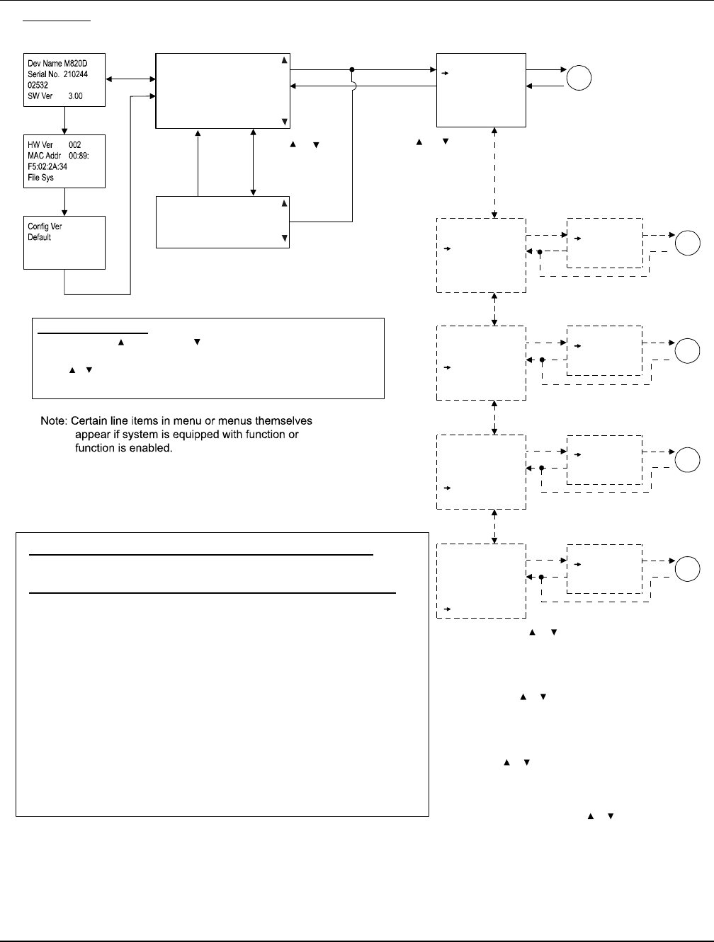
UM1M820BNA User Instructions
Issue AH, March 4, 2013 Spec No. 1M820BNA (Model M820B)
Spec No. 1M820DNA (Model M820D)
82 Chapter 3. Local Display Menus
This document is property of Emerson Network Power, Energy Systems, North America, Inc. and contains confidential and proprietary information owned by Emerson Network Power, Energy
Systems, North America, Inc. Any copying, use, or disclosure of it without the written permission of Emerson Network Power, Energy Systems, North America, Inc. is strictly prohibited.
Figure 8 (cont’d on next page)
Local Menu Flow Diagrams
Main Menu
S tatu s
Settings
ECO Mode
Manual
09:20:20
Float Charge
##.#V ###A
Auto No Alm
Number of Rec 4
E N T
E S C
E N T
Main Menu
S tatu s
Settings
Select User
Admin
Enter Password
*
Select User
Admin
Enter Password
*
Select User
Admin
Enter Password
*
Select User
Admin
Enter Password
*
E N T
E S C
E N T
A
B
Main Screen Main Menu
ESC
Quick Setting
E N T
E S C
ECO Mode
Manual
Quick Setting
Main Menu
S ta tu s
Settings
ECO Mode
Manual
Quick Setting
E N T
E S C
Main Menu
S ta tu s
Settings
ECO Mode
Manual
Quick Setting
E N T
E S C
Main Menu
S ta tu s
Settings
ECO Mode
Manual
Quick Setting
E N T
E N T
E N T
E N T
E S CE S C
E S C
E N T
C
E N T
D
E N T
E
*
*
*
*
* Note: Use or to move the cursor
to the Select User field. Press ENT
to select a different User if required.
To select a User, press ENT
to highlight the Select User field,
and use or to select a User.
Press ENT to select the User displayed
in the Select User field. Note that only
Users programmed into the ACU+ are shown.
Users are programmed via the Web Interface.
Use or to move the cursor
to the Enter Password field.
Press ENT to enter a password.
To enter password, press ENT
to highlight bit, and use or
to choose character. Press ENT
to accept and move to the
next character. Press ENT again
to accept password.
Press or
to move cursor in
MAIN MENU screen.
Press ENT to enter
selected sub-menu.
Press or
to move to
next or previous
screen.
E S C
E S C
E S C
E S C
INFO SCREENS
(Returns to MAIN SCREEN
after a preset time period.)
Date and time are
alternately displayed.
In the MAIN SCREEN:
Press ENT and , or ENT and at the same time
to change the contrast of the LCD.
Press , , and ESC at the same time to log out.
Press ENT and ESC at the same time to reset the ACU+ Controller.
Local and Remote Access Passwords (set via the Web Interface)
Maximum 13 Characters (0-9, a-z, A-Z, _ )
Access Level Default Password Authority
Once a password is entered, it remains in effect for a preset time period
to allow navigating between menus without re-entering the password.
A User has access to his/her level menus,
plus all menus of the lesser access levels.
Level A (Browser) none set Browse System Information.
Level B (Operator) none set Change System Control Settings.
Level C (Engineer) none set Modify System Parameters.
Download Configuration File.
Level D (Administrator) 1 Update OS Application.
Modify, Add, Delete User Information.
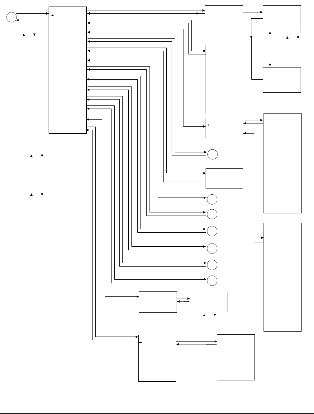
User Instructions UM1M820BNA
Spec No. 1M820BNA (Model M820B) Issue AH, March 4, 2013
Spec No. 1M820DNA (Model M820D)
Chapter 3. Local Display Menus 83
This document is property of Emerson Network Power, Energy Systems, North America, Inc. and contains confidential and proprietary information owned by Emerson Network Power, Energy
Systems, North America, Inc. Any copying, use, or disclosure of it without the written permission of Emerson Network Power, Energy Systems, North America, Inc. is strictly prohibited.
Figure 8 (cont’d from previous page, cont’d on next page)
Local Menu Flow Diagrams
Status
Active Alarms
Power System
Rectifier
Battery
DC
AC
EIB
SMDU
Converter
SMDUP
SMTemp
Alarm History
Sys Inventory
E S C
A
E N T Active Alarms
Minor: 0
Major: 0
Critical: 2
System Voltage
54.0 V
System Load
0.0 A
Mtnc Run Time
1.3 h
Alarm Status
No Alm
Power Split
Master
IB2 T2
21 deg. C
...
SMTemp1 T1
21 deg. C
DC Voltage
53.8 V
DC Current
8.5 A
Temperature
30 deg. C
DC Status
On
AC On/Off
On
Rated Current
35 A
Walk-In
Disabled
Rectifier ID
1
Rect Phase
A
Rectifier SN
010700213
Running Time
200 h
AC Voltage
224 V
Rectifier
Rect Group
Rect #1
Rect #2
1 Rect AC
Mains Failure
081104 8:00:12
Critical
2 Power System
CAN Comm Fail
081104 8:05:02
Critical
DC Voltage
54.0 V
Load Current
0.0 A
SYS Inventory
ACU+
Rect #1
Rect #2
EIB 1
IB 1
SMDUP 1
Conv #1
Conv #2
SMTemp 1
ENT
ENT ENT
ENT
ENT
ENT
ESC
ESC
ESC
ESC
ESC
ESC
ESC
ESC
ESC
ENT
ENT
ENT
ESC
ESC
ENT
ENT
ESC
ENT
ESC
ENT
ENT
Press or
to cycle through
list of alarms.
Press ESC to return
to STATUS menu.
Press or
to cycle through
list of alarms.
ENT
ESC
1 IB2
DI3 Alarm
100629 12:18:35
100629 12:19:52
Device Name
ACU+
Part Number
M820D
Product Ver
001
SW Version
2.25
Serial Number
21024402512
ENT
ESC
ENT
ESC
Power System
DC
Alarm History
Minor: 0
Major: 0
Critical: 1
Press or
to move cursor in
STATUS screen.
Press ENT to enter
selected sub-menu.
To View Parameters:
Press or to move up and
down list of parameters.
To Select a Sub-Menu:
Press or to move cursor in
menu screen (selects menu item).
Press ENT to enter selected sub-menu.
Note:
For a complete list of alarms that can be displayed
in the STATUS Active Alarm menus, see the table
titled “Available Alarms”in the Operation Chapter.
A3
ESC
A2
A5
A6
Average Voltage
52.0 V
Total Current
0.2 A
Number of Rects
2
Num Rects Comm
2
Sys Cap Used
0.9 %
Max Cap Used
3.4 %
Min Cap Used
0.0 %
Rated Voltage
52.0 V
AC Phases
Single Phase
Max Curr Limit
462.2 A
Total Rated Cur
382.0 A
Rect Group
Battery
AC
EIB
ESC
A4 SMDU
Converter
Similar information
is displayed for each
device in the system.
SMDUP
A7 SMTemp
Rect #1
A1
ENT
ESC
Temp.
Probes
set as
“ambient”
show up
here.
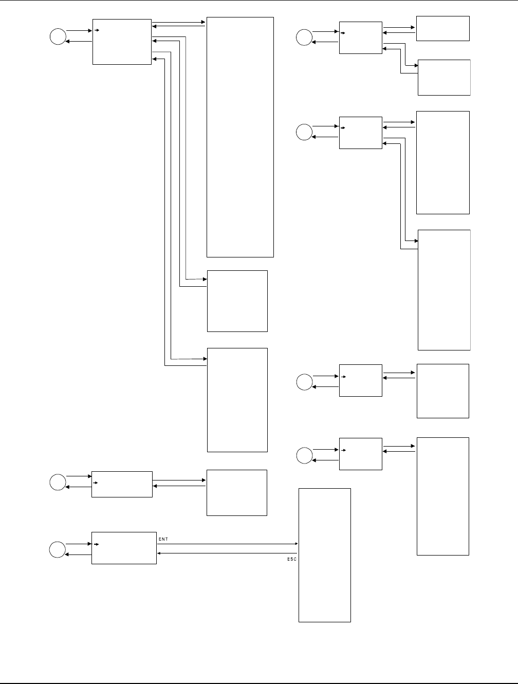
UM1M820BNA User Instructions
Issue AH, March 4, 2013 Spec No. 1M820BNA (Model M820B)
Spec No. 1M820DNA (Model M820D)
84 Chapter 3. Local Display Menus
This document is property of Emerson Network Power, Energy Systems, North America, Inc. and contains confidential and proprietary information owned by Emerson Network Power, Energy
Systems, North America, Inc. Any copying, use, or disclosure of it without the written permission of Emerson Network Power, Energy Systems, North America, Inc. is strictly prohibited.
Figure 8 (cont’d from previous page, cont’d on next page)
Local Menu Flow Diagrams
ESC
A5
ENT
Output Voltage
48.2 V
Output Current
0.0 A
Temperature
25.0 deg. C
On/Off Status
On
Rated Current
xxx.x A
Converter ID
1
Converter SN
xxxxxx
Running Time
200 h
Conv #1
SMDUP 1
ESC
A6
ENT SMDUP
SMDUP 1
Current 1
0.0 A
...
Current 25
0.0 A
Shunt Settable
By Software
ESC
A3
ENT
ESC
A2
ENT
EIB
EIB 1
Block In-Use
8
Voltage 1
0.0 V
Voltage 2
0.0 V
Voltage 3
0.0 V
Voltage 4
0.0 V
Voltage 5
0.0 V
Voltage 6
0.0 V
Voltage 7
0.0 V
Voltage 8
0.0 V
EIB 1
Battery Voltage
53.8 V
Total Batt Curr
0.0 A
Comp Temp
21 deg. C
Short BOD Time
2 min
ShortBODCounter
8
Long BOD Time
1 min
LongBODCounter
7
Full BOD Time
0 min
FullBODCounter
1
Remaining Time
360.0 hr
LiBatt AvgTemp
20 deg. C
Num Installed
8
NumDisconnected
0
Num No Reply
0
InventUpdating
No
IB2 T1
21 deg. C
...
Batt Group
Battery Voltage
0.0 V
Battery Current
0.0 A
Batt Rating(Ah)
300 Ah
Batt Cap (%)
100.0 %
Battery
Batt Group
Battery 1
Battery 2
LiBattery1
ESC
A1
ENT
AC
Rect AC
Phase A Voltage
253 V
Phase B Voltage
253 V
Phase C Voltage
254 V
Battery 1
Batt Voltage
52.3 V
Batt Current
0.0 A
State of Charge
98.8%
Batt Term Volt
52.3 V
Cell Temp
21.0 deg. C
Switch Temp
21.0 deg. C
Batt LED Status
Full Green
LiBattery1
Rect AC
ESC
ENT
ENT
ESC
ENT
ESC
ESC
ENT
Converter
Conv Group
Conv #1
Conv #2
ENT
ESC
ENT
ESC
SMTemp
ESC
A7
ENT SMTemp
SMTemp 1
SMTemp1 Temp1
21 deg. C
...
SMTemp1 Temp8
21 deg. C
...
SMTemp8 Temp1
21 deg. C
...
SMTemp8 Temp8
21 deg. C
Temp T1 Status
Normal
...
Temp T8 Status
Normal
ENT
ESC
Average Voltage
52.0 V
Total Current
0.2 A
Number of Convs
2
Num Convs Comm
2
Rated Voltage
52.0 V
Total Rated Cur
xxx.x A
Max Curr Limit
31.3 A
Conv Group
ENT
ESC
ESC
A4
ENT
Bus Bar Voltage
54.0 V
Load 1 Current
0.0 A
SMDU 1
SMDU
SMDU Group
SMDU 1
ENT
ESC
Num of SMDUs
1
SMDU Group
ENT
ESC
Temp. Probes
set as “battery”
show up here.
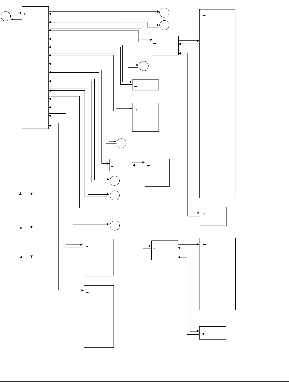
User Instructions UM1M820BNA
Spec No. 1M820BNA (Model M820B) Issue AH, March 4, 2013
Spec No. 1M820DNA (Model M820D)
Chapter 3. Local Display Menus 85
This document is property of Emerson Network Power, Energy Systems, North America, Inc. and contains confidential and proprietary information owned by Emerson Network Power, Energy
Systems, North America, Inc. Any copying, use, or disclosure of it without the written permission of Emerson Network Power, Energy Systems, North America, Inc. is strictly prohibited.
Figure 8 (cont’d from previous page, cont’d on next page)
Local Menu Flow Diagrams
Settings
Alarm Setting
Power System
Rectifier
Battery
BattFuseUnit
DC
LVD
AC
EIB
SMDU
Converter
SMTemp
Communication
Controller
ESC
B1
B
B3
B2
ENT
ENT
ENT
ENT
ENT
ENT
ESC
ESC
ESC
B5
B4
ESC
ESC
ESC
ESC
ESC
ESC
ESC
ENT
ENT
ENT
ENT
ENT
ENT
Language
English
Date
2010-06-30
Time
13:04:10
Keypad Voice
On (on / off)
Reload Config
Yes
Download Config
Yes
Auto Config
Yes
DHCP
Disabled (enabled / disabled)
IP Address
126.50.143.70
Subnet Mask
255.255.255.0
Default Gateway
0.0.0.0
Rectifier
All Rect Set
Rect #1
Rect #2
Rectifier ID
2 (1-999)
Rect Phase
B (A / B / C)
HVSD
Enabled (enabled / disabled)
HVSD Limit
59.0 V (56.0-59.5) (28.0-29.7)
Restart on HVSD
Enabled (enabled / disabled)
HVSD Restart T
300 s (0-300)
Start Interval
0 s (0-10)
Walk-In
Enabled (enabled / disabled)
Walk-In Time
8 s (8-128)
Turn On ACOverV
No (no / yes)
ECO Mode
Disabled (enabled / disabled)
Best Oper Point
80 % (30-90)
Fluct Range
10 % (1-50)
Energy Save Pt
45 % (10-90)
Cycle Period
168 h (1-8760)
Rects ON Time
120 min (0-255)
Turn Off Delay
5 min (1-60)
Input Curr Lmt
30 A (1-50)
MixHE Power
Non-Derate (non-derate / derate)
DG Pwr Lmt
Enabled (disabled / enabled)
Diesel DI Input
None (none / Digital Input 1 / ... / Digital Input8)
DG Pwr Lmt Pt
40.0 % (40-100)
Current Limit
Enabled (enabled / disabled)
Current Limit Pt
400 A (dependent on # of rectifiers)
ESC
ENT
ESC
ENT
AC
Rect AC
Nominal PH-Volt
220 V (50-450)
Mains Fail Alm1
20 % (0.0-100.0)
Mains Fail Alm2
20 % (0.0-100.0)
ENT
ESC
All Rect Set
Alarm Setting
Power System
Battery
LVD
EIB
Rect #1
Communication
Controller
Rect AC
ENT
ENT
ESC
B6
ESC
SMDU
B7
ESC
SMTemp
ESC
ENT
Shunt Current
150.0 A (50.0-50000.0)
Shunt Voltage
25.0 mV (1.0-150.0)
LoadShuntExist
No (No / Yes)
DC
Num of Bat Fuse
0
BattFuseUnit
Converter
All Conv Set
Conv #1
Conv #2
Output Voltage
52.0 V (48.0-55.5)
Under Voltage
47.0 V (42.0-55.0)
Over Voltage
56.0 V (49.0-59.0)
Over Current
500 A (1-500)
HVSD
Enabled (enabled / disabled)
HVSD Limit
59.0 V (48.0-60.0)
Current Limit
Enabled (enabled / disabled)
Current Limit Pt
94 A (dependent on # of converters)
ESC
ENT
ENT
All Conv Set
Set Conv ID
1 (1-999)
ESC
Conv #1
To Select a Sub-Menu:
Press or to move
cursor in menu screen
(selects menu item).
Press ENT to enter
selected sub-menu.
To Change a Parameter:
Press or to move
up and down list of
parameters.
Press ENT to highlight
selected parameter.
Press or to change
highlighted value.
Press ENT to
make the change.
Press ESC to
cancel the change.
The parameter values
shown in ( ) are the
adjustment range or
acceptable values.
Factory default settings
are listed in the ACU+
Configuration Drawing (C-dwg)
furnished with your system.
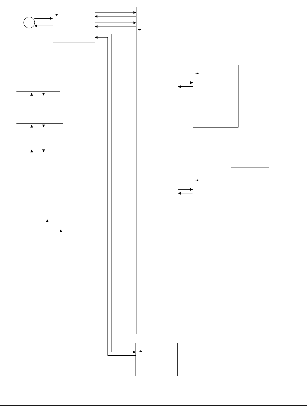
UM1M820BNA User Instructions
Issue AH, March 4, 2013 Spec No. 1M820BNA (Model M820B)
Spec No. 1M820DNA (Model M820D)
86 Chapter 3. Local Display Menus
This document is property of Emerson Network Power, Energy Systems, North America, Inc. and contains confidential and proprietary information owned by Emerson Network Power, Energy
Systems, North America, Inc. Any copying, use, or disclosure of it without the written permission of Emerson Network Power, Energy Systems, North America, Inc. is strictly prohibited.
Figure 8 (cont’d from previous page, cont’d on next page)
Local Menu Flow Diagrams
Alarm Setting
Alm Severity
Alarm Relay
Alarm Param
Alm Severity or
Alarm Relay
Power System
Rect Group
Rectifier
Battery Group
Battery
SMDU Battery
EIB Battery
SM Battery
LargeDU Batt
SMBRC Battery
OB Batt Fuse
SMDU Bat Fuse
DC Distr
DC Fuse Unit
SMDU DC Fuse
SMDUP DC Fuse
LVD Unit
SMDU LVD
LargeDU LVD
Rectifier AC
SMAC
IB
EIB
SMDU 1
SMDU 2
SMDU 3
SMDU 4
SMDU 5
SMDU 6
SMDU 7
SMDU 8
Converter Grp
Converter
SMIO 1
SMIO Unit 3
SMIO Unit 4
SMIO Unit 5
SMIO Unit 6
SMIO Unit 7
SMIO Unit 8
LargeDUACDist
AC Distributi
DC Distributi
Dsl Gen Group
Dsl Generator
Rect Group 2
Group 2 Rect
Rect Group 3
Group 3 Rect
Rect Group 4
Group 4 Rect
SMDUP
SMBRC Unit
Fuel Tank Grp
Fuel Tank
SMTemp Group
SMTemp 1
SMTemp 2
SMTemp 3
SMTemp 4
SMTemp 5
SMTemp 6
SMTemp 7
SMTemp 8
AC Failure
Major (none / minor / major / critical)
Rect Temp High
Major (none / minor / major / critical)
Rect Fault
Major (none / minor / major / critical)
HVSD
Major (none / minor / major / critical)
(see Available Alarms
Table for complete list
of available alarms)
Alarm Voice
On (on / off / 3 min / 10 min / 1 hour / 4 hour)
Block Alarm
Normal (normal / blocked)
Clr Alm Hist
Yes
AC Failure
Relay # (none / relay 1 / ... / relay 13)
Rect Temp High
Relay # (none / relay 1 / ... / relay 13)
Rect Fault
Relay # (none / relay 1 / ... / relay 13)
HVSD
Relay # (none / relay 1 / ... / relay 13)
(see Available Alarms
Table for complete list
of available alarms)
ENT
ENT
ESC
ESC
ESC
ESC
ESC
ENT
ENT
ENT
ESC
B1
ENT
Rectifier
Rectifier
Alarm Param
To Change a Parameter:
Press or to move up and
down list of parameters.
Press ENT to highlight selected parameter.
Press or to change highlighted value.
Press ENT to make the change.
Press ESC to cancel the change.
The parameter values shown in ( ) are the
adjustment range or acceptable values.
Factory default settings are listed in the
ACU+ Configuration Drawing (C-dwg)
furnished with your system.
Note:
After setting the Alarm Severity Level,
press ENT and together to jump to the
related Alarm Relay setting menu for this
alarm. Press ENT and together again
to return to the previous Alarm Severity
Level screen.
To Select a Sub-Menu:
Press or to move cursor in
menu screen (selects menu item).
Press ENT to enter selected sub-menu.
Note:
The Alarm Severity and Alarm Relay screens
are the same so only one is shown here. Also,
the alarms for the Device Groups is lengthy
so only part of the alarms for the Rectifier
Device Group is shown. See the table titled
“Available Alarms”in the Operation Chapter
for a complete listing of the Device Groups alarms.
Alarm Severity Screen
Alarm Relay Screen
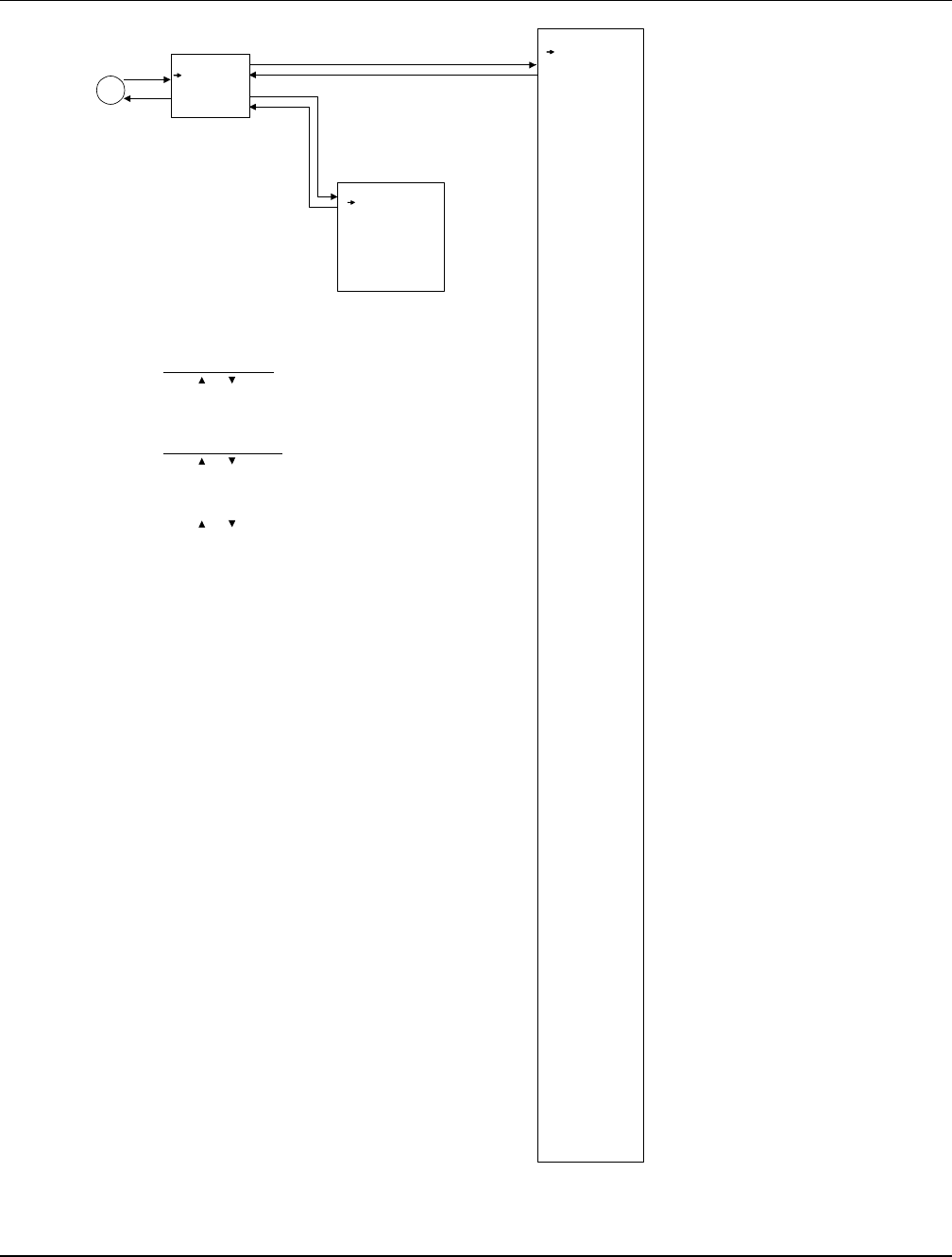
User Instructions UM1M820BNA
Spec No. 1M820BNA (Model M820B) Issue AH, March 4, 2013
Spec No. 1M820DNA (Model M820D)
Chapter 3. Local Display Menus 87
This document is property of Emerson Network Power, Energy Systems, North America, Inc. and contains confidential and proprietary information owned by Emerson Network Power, Energy
Systems, North America, Inc. Any copying, use, or disclosure of it without the written permission of Emerson Network Power, Energy Systems, North America, Inc. is strictly prohibited.
Figure 8 (cont’d from previous page, cont’d on next page)
Local Menu Flow Diagrams
Power System
General
Power Split
Slave Curr Lmt
60 % (10-90)
Delta Volt
0.5 V (0.1-2.0)
Proportion Coeff
30.0 (0-100)
Integral Time
60 s (10-2000)
ENT
ENT
ESC
ESC
ESC
B2
ENT
Power Split
To Change a Parameter:
Press or to move up and
down list of parameters.
Press ENT to highlight selected parameter.
Press or to change highlighted value.
Press ENT to make the change.
Press ESC to cancel the change.
The parameter values shown in ( ) are the
adjustment range or acceptable values.
Factory default settings are listed in the
ACU+ Configuration Drawing (C-dwg)
furnished with your system.
To Select a Sub-Menu:
Press or to move cursor in
menu screen (selects menu item).
Press ENT to enter selected sub-menu.
Auto/Man State
Auto (auto / manual)
Manual Mode Lmt
1 h (0-24)
Mtnc Cycle Time
360 days (10-7200)
EStop/EShutdown
Disabled (disabled / EStop / EShutdown)
Load Curr Alarm
3000 A (0-4000)
Alarm Blocked
Normal (normal / blocked)
Rect Expansion
Inactive (inactive / primary / secondary)
Address (Slave)
201 (201 / 202 / 203)
Over Voltage 1
57.0 V (40-60) (20-30)
Over Voltage 2
58.0 V (40-60) (20-30)
Under Voltage 1
48.0 V (40-60) (20-30)
Under Voltage 2
44.0 V (40-60) (20-30)
Fail Safe
enable (disable / enable)
Hybrid Mode
disable (disable / fixed daily / capacity)
DG Run Overtemp
enable (disable / enable)
DG Run Time
60 min (30-120)
DG Used
DG1 (DG1 / DG2 / Both)
DI for Grid
DI3 (DI1 / ... / DI8)
DOD
40.0 % (20-80)
Dsch Duration
12 hours (1-22)
Start Dsch Time
19 clock (0-24)
High Load Set
40.0 % (20-80)
Equal StartTime
8 clock (0-24)
DG Alarm Delay
60 sec. (30-180)
Fail Safe
Normally Open (normally open / normally close)
Contactor Mode
Master Ctrlr (Master Ctrlr / Slave Ctrlr)
Relay Test
Disabled (disabled / automatic / individual)
Relay Test Time
45 sec. (0-120)
HighLoadLevel1
70% (0-100)
HighLoadLevel2
85% (0-100)
DI1 Alarm State
High (Low / High)
...
DI8 Alarm State
High (Low / High)
Amb Temp Sensor
IB2 T2 (None / SMTemp8 T8 / ... / SMTemp8 T1 / ... /
SMTemp1 T8 / ... / SMTemp1 T1 / EIB T2 / EIB T1 /
IB2 T2 / IB2 T1 / System T3 / System T2 / System T1 /
Average / Maximum)
Amb Temp High2
100.0 deg. C (-40 to +100)
Amb Temp High1
90.0 deg. C (-40 to +100)
Amb Temp Low
-10.0 deg. C (-40 to +100)
System Temp1
None (None / Battery / Ambient)
System Temp2
None (None / Battery / Ambient)
System Temp3
None (None / Battery / Ambient)
IB2 Temp1
Battery (None / Battery / Ambient)
IB2 Temp2
Ambient (None / Battery / Ambient)
EIB Temp1
None (None / Battery / Ambient)
EIB Temp2
None (None / Battery / Ambient)
Special
Configurations
Only
General
The temperature
monitored by the
Temp. Probe selected
here is displayed on
the Homepage of
the Web Interface.
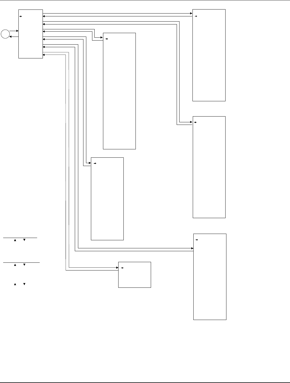
UM1M820BNA User Instructions
Issue AH, March 4, 2013 Spec No. 1M820BNA (Model M820B)
Spec No. 1M820DNA (Model M820D)
88 Chapter 3. Local Display Menus
This document is property of Emerson Network Power, Energy Systems, North America, Inc. and contains confidential and proprietary information owned by Emerson Network Power, Energy
Systems, North America, Inc. Any copying, use, or disclosure of it without the written permission of Emerson Network Power, Energy Systems, North America, Inc. is strictly prohibited.
Figure 8 (cont’d from previous page, cont’d on next page)
Local Menu Flow Diagrams
Battery
Basic
Charge
Test
Temp Comp
Capacity
Battery 1
Num Batt Shunts
1 (0-2)
Calc Batt Curr
No (no / yes)
Low Capacity Pt
75 % (25-100)
Current Limited
No (no / yes)
BTRM TempSensor
IB2 T2 (None / SMTemp8 T8 / ... / SMTemp8 T1 / ... /
SMTemp1 T8 / ... / SMTemp1 T1 / EIB T2 / EIB T1 /
IB2 T2 / IB2 T1 / System T3 / System T2 / System T1 /
Average SMBRC / Average / Maximum)
BTRM Temp High2
100.0 deg. C (0-100)
BTRM Temp High1
90.0 deg. C (0-100)
BTRM Action
Disabled (disabled / lower voltage)
BTRM Voltage
51.0 V (45-55) (22.5-27.5)
ABCL Point
20A (1-60)
Float Voltage
54.0 V (42.0-58.0) (21.0-29.0)
EQ Voltage
56.5 V (42.0-58.0) (21.0-29.0)
Batt Curr Limit
0.10 C10 (0.10-0.25)
Over Curr Lmt
0.30 C10 (0.30-1.00)
Auto EQ
No (no / yes)
EQ Start Curr
0.060 C10 (0.040-0.080)
EQ Start Cap
80.0 % (0-99)
EQ Stop Curr
0.010 C10 (0.002-0.020)
EQ Stop Delay
180 min (0-1440)
Maximum EQ Time
1080 min (60-2880)
Cyc EQ
No (no/yes)
Cyc EQ Interval
100 days (2-365)
Cyc EQ Duration
720 min (30-2880)
Test Volt Lmt
45.0 V (43.0-53.5) (21.5-27.0)
Test End Volt
45.2 V (43.2-53.5) (21.5-27.0)
End Test Time
100 min (10-1440)
EndTestCapacity
70 % (0-100)
RecordThreshold
0.100 V (0.100-1.000)
AC Fail Test
Disabled (disabled / enabled)
Planned Tests
0 (0-12)
Test 1 (M-D Hr)
10-21 10
Const Curr Test
Disabled (disabled / enabled)
ConstCurrT Curr
9999.0 A (1-9999)
Short Test
Disabled (disabled / enabled)
ShortTest Cycle
30 days (1-365)
Short Test Time
5 min (1-60)
Max Diff Curr
0.05 C10 (0.00-1.00)
BattTestLowCap
99 % (70-100)
Temp CompCenter
25.0 deg. C (0.0-40.0)
Temp Comp Coeff
72.0 mV/deg. C (0.0-500.0)
TempComp Sensor
None (None / SMTemp8 T8 / ... / SMTemp8 T1 / ... /
SMTemp1 T8 / ... / SMTemp1 T1 / EIB T2 / EIB T1 /
IB2 T2 / IB2 T1 / System T3 / System T2 / System T1 /
Average SMBRC / Average / Maximum)
Comp Temp High2
60 deg. C (0-100)
Comp Temp High1
50 deg. C (0-100)
Comp Temp Low
-10.0 deg. C (-40 to +100)
Temp Comp Max V
29.0 (42.0-58.0) (21.0-29.0)
Temp Comp Clamp
Enabled (disabled / enabled)
Temp Comp Min V
26.0 (42.0-58.0) (21.0-29.0) Charging Eff
96 % (10-100)
Time 0.1C10
10.00 h (0.00-10.00)
Time 0.2C10
4.90 h (0.00-10.00)
Time 0.3C10
3.00 h (0.00-10.00)
Time 0.4C10
2.00 h (0.00-10.00)
Time 0.5C10
1.40 h (0.00-10.00)
Time 0.6C10
1.20 h (0.00-10.00)
Time 0.7C10
1.10 h (0.00-10.00)
Time 0.8C10
0.90 h (0.00-10.00)
Time 0.9C10
0.70 h (0.00-10.00)
Time 1.0C10
0.50 h (0.00-10.00)
Rated Capacity
600.0 Ah (50.0-50000.0)
Shunt Current
800.0 A (50.0-50000.0)
Shunt Voltage
25.0 mv (1.0-150.0)
ENT
ENT
ENT
ENT
ENT
ESC
ESC
ESC
ESC
ESC
ESC
ENT
ESC
B3
ENT
Basic
Charge
Test
Temp Comp
Capacity
Battery 1
To Change a Parameter:
Press or to move up and
down list of parameters.
Press ENT to highlight selected parameter.
Press or to change highlighted value.
Press ENT to make the change.
Press ESC to cancel the change.
The parameter values shown in ( ) are the
adjustment range or acceptable values.
Factory default settings are listed in the
ACU+ Configuration Drawing (C-dwg)
furnished with your system.
To Select a Sub-Menu:
Press or to move cursor in
menu screen (selects menu item).
Press ENT to enter selected sub-menu.
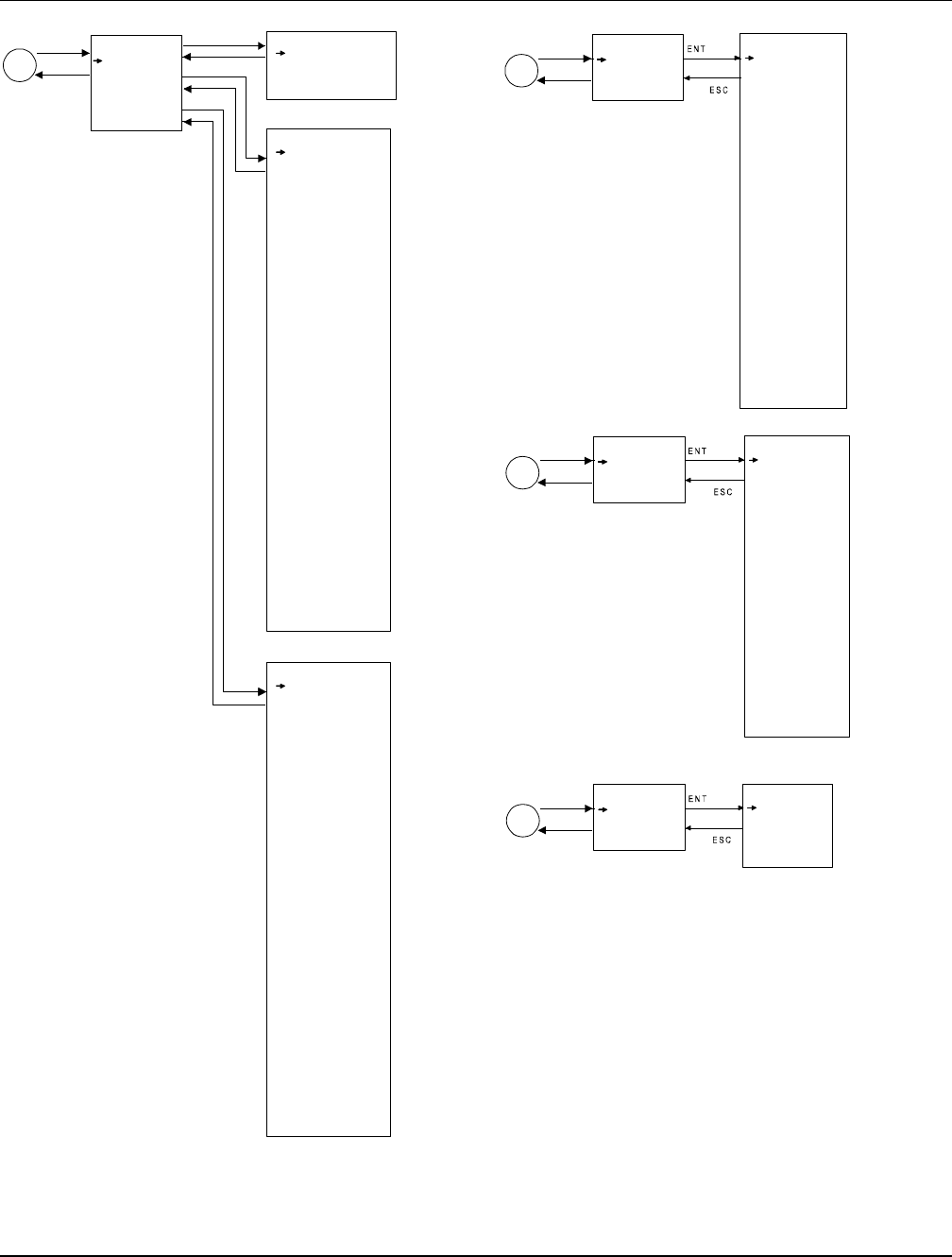
User Instructions UM1M820BNA
Spec No. 1M820BNA (Model M820B) Issue AH, March 4, 2013
Spec No. 1M820DNA (Model M820D)
Chapter 3. Local Display Menus 89
This document is property of Emerson Network Power, Energy Systems, North America, Inc. and contains confidential and proprietary information owned by Emerson Network Power, Energy
Systems, North America, Inc. Any copying, use, or disclosure of it without the written permission of Emerson Network Power, Energy Systems, North America, Inc. is strictly prohibited.
Figure 8 (cont’d from previous page, cont’d on next page)
Local Menu Flow Diagrams
ESC
B5
ENT EIB
EIB 1
Shunt 1 Current
500.0 A (50.0-50000.0)
Shunt 1 Voltage
75.0 mV (1.0-150.0)
Shunt 2 Current
500.0 A (50.0-50000.0)
Shunt 2 Voltage
75.0 mV (1.0-150.0)
Shunt 3 Current
500.0 A (50.0-50000.0)
Shunt 3 Voltage
75.0 mV (1.0-150.0)
Num Batt Shunts
0 (0-3)
Num Load Shunts
0 (0-3)
Voltage Type
48 (Block 4) (disable / 24 (block 2) /
midpoint / 48 (block 4))
Blk V Diff(12V)
1 (0 - 2)
Blk V Diff(Mid)
1 (0 - 2)
Block In-Use
0 (0-8)
EIB 1
ESC
B7
ENT SMTemp
SMTemp 1
T1 Assign Equip
Ambient (None / Battery / Ambient)
...
T8 Assign Equip
None (None / Battery / Ambient)
SMTemp 1
ESC
B6
ENT SMDU
SMDU 1
Shunt 1 Voltage
75 mV (25-75)
Shunt 1 Current
500 A (100-2000)
Shunt 2 Voltage
75 mV (25-75)
Shunt 2 Current
500 A (100-2000)
Shunt 3 Voltage
75 mV (25-75)
Shunt 3 Current
500 A (100-2000)
Shunt 4 Voltage
75 mV (25-75)
Shunt 4 Current
500 A (100-2000)
Shunt 5 Voltage
75 mV (25-75)
Shunt 5 Current
500 A (100-2000)
SMDU 1
ESC
B4
ENT
ENT
LVD
LVD Group
LVD Unit
SMDU 1 LVD
HTD Recon Point
38.0 deg. C (20-80)
HTD Point
40.0 deg. C (20-80)
LVD Group
ESC
LVD1
Enable (enable / disable)
LVD1 Mode
Voltage (voltage / time)
LVD1 Volt
42.0 V (40-60) (20-30)
LVD1 Recon Volt
49.0 V (40-60) (20-30)
LVD1 ReconDelay
1 min (1-30)
LVD1 Time
300 min (30-1000)
LVD1 Dependency
None (none / LVD1 / LVD2)
LVD2
Enable (enable / disable)
LVD2 Mode
Voltage (voltage / time)
LVD2 Volt
42.0 V (40-60) (20-30)
LVD2 Recon Volt
49.0 V (40-60) (20-30)
LVD2 ReconDelay
1 min (1-30)
LVD2 Time
600 min (30-1000)
LVD2 Dependency
None (none / LVD1 / LVD2)
HTD1
Disable (enable / disable)
HTD2
Disable (enabled / disable)
LVD Type
Bistable (bistable / mono-stable / mono w/sample)
LVD Unit
LVD 1
Enable (enable / disable)
LVD 1 Mode
Voltage (voltage / time)
LVD 1 Voltage
42.0 V (40-60) (20-30)
LVD1 Recon Volt
49.0 V (40-60) (20-30)
LVD1 ReconDelay
1 min (1-30)
LVD 1 Time
300 min (30-1000)
LVD1 Dependency
None (none / LVD1 / LVD2)
LVD 2
Enable (enable / disable)
LVD 2 Mode
Voltage (voltage / time)
LVD 2 Voltage
42.0 V (40-60) (20-30)
LVD2 Recon Volt
49.0 V (40-60) (20-30)
LVD2 ReconDelay
1 min (1-30)
LVD 2 Time
600 min (30-1000)
LVD2 Dependency
None (none / LVD1 / LVD2)
HTD 1
Disable (enable / disable)
HTD 2
Disable (enabled / disable)
SMDU 1 LVD
ENT
ESC
ENT
ESC
Displayed when “Voltage Type”
set for other then “disable”and
“Block In-Use”set for other then “0”.

UM1M820BNA User Instructions
Issue AH, March 4, 2013 Spec No. 1M820BNA (Model M820B)
Spec No. 1M820DNA (Model M820D)
90 Chapter 3. Local Display Menus
This document is property of Emerson Network Power, Energy Systems, North America, Inc. and contains confidential and proprietary information owned by Emerson Network Power, Energy
Systems, North America, Inc. Any copying, use, or disclosure of it without the written permission of Emerson Network Power, Energy Systems, North America, Inc. is strictly prohibited.
Figure 8 (cont’d from previous page, cont’d on next page)
Local Menu Flow Diagrams
Manual
Man/Auto Set
Power System
Rectifier
Batt Group
LVD
EIB
Converter
SMTemp
Note
Items marked with an asterisk (*) can be changed
while in Auto Mode. Before any other settings in
the Manual submenus can be changed, you must
first place the controller into Manual Mode. Use
the MAN/AUTO SET menu to change the Controller
from Auto Mode to Manual Mode.
When you return to Auto Mode, any settings changed
in Manual Mode are returned to their previous setting
(setting before being placed in Manual Mode).
D
ENT
ENT
ENT
ENT
ENT
ENT
ESC
ESC
ESC
ESC
ESC
ESC
Auto/Man State
Auto (auto / manual)
Relay Output 1
Active (active / not active)
...
Relay Output 8
Active (active/ not active)
Clr MtncRunTime
Yes
ENT
ECO Mode
Enabled (disabled / enabled)
Best Oper Point
80 % (30-90)
Energy Save Pt
45 % (10-90)
Fluct Range
10 % (1-50)
Cycle Period
168 hour (1-8760)
Rects ON Time
120 min (0-255)
Turn Off Delay
5 min (1-60)
C
ENT
ESC
ECO Mode Man/Auto Set
Power System
To Change a Parameter:
Press or to move up and
down list of parameters.
Press ENT to highlight selected parameter.
Press or to change highlighted value.
Press ENT to make the change.
Press ESC to cancel the change.
The parameter values shown in ( ) are the
adjustment range or acceptable values.
Factory default settings are listed in the
ACU+ Configuration Drawing (C-dwg)
furnished with your system.
To Select a Sub-Menu:
Press or to move cursor in
menu screen (selects menu item).
Press ENT to enter selected sub-menu.
ESC
ESC
LVD
LVD Group
LVD Unit
ENT
LVD1 Control
Connected (disconnected)
LVD2 Control
Connected (disconnected)
LVD Unit
SMTemp
SMTemp Group
SMTemp 1
SMTemp 2
ENT
ESC
ESC
Converter Trim
42.0V (42.0-58.0)
DC On/Off Ctrl
Switch On All (Switch Off All / Switch On All)
Conv LED Ctrl
Stop Flashing (All Flashing / Stop Flashing)
Fan Speed Ctrl
Auto Speed (Full Speed / Auto Speed)
Confirm ID
Yes
Clear Conv Lost
Clear
Clear Comm Fail
Yes
ClrAllCommFail
Yes
All Conv Ctrl
DC On/Off Ctrl
On (On / Off)
Over Volt Reset
On (On / Off)
LED Control
Cancel (Flash / Cancel)
Conv #1
Converter
All Conv Ctrl
Conv #1
Conv #2
ENT
*
*
Rectifier
All Rect Ctrl
Rect #1
Rect #2
EQ/FLT Control
Float Charge (equalize charge)
BattTestControl
Stop (start)
Reset Batt Cap
Yes
Clr Bad Bat Alm
Yes
Clr LiBatt Lost
Clear
ClrLiBatComFail
Clear
Clr AbnlCur Alm
Yes
Clr Cur Imb Alm
Yes
ClrBatTestFail
Yes
ENT ESC
ESC
Rectifier Trim
53.9 V (42.0-58.0) (21.0-29.0)
DC On/Off Ctrl
Switch On All (switch off all)
AC On/Off Ctrl
Switch On All (switch off all)
Rect LED Ctrl
Stop Flashing (all flashing)
Fan Speed Ctrl
Auto Speed (full speed)
Confirm ID/PH
Yes
Clear Rect Lost
Clear
Reset Cycle Alm
Clear
Clear Comm Fail
Yes
ENT
Batt Group
All Rect Ctrl
DC On/Off Ctrl
On (on / off)
AC On/Off Ctrl
On (on / off)
LED Control
LED Control (LED control / cancel)
Rectifier Reset
Reset
Rect #1
*
*
*
*
*
*
*
*
*
*
*
*
*
*
EIB 1
Relay Output 9
Active (active/ not active)
Relay Output 10
Active (active/ not active)
Relay Output 11
Active (active/ not active)
Relay Output 12
Active (active/ not active)
Relay Output 13
Active (active/ not active)
ESC
EIB
EIB 1
ENT
ESC
ENT
ENT
ESC
*
*
*
*
ENT
ESC
ESC
Clr SMTemp Lost
Clear *
SMTemp Group
Clr Probe Alm
Clear *
SMTemp 1
ENT
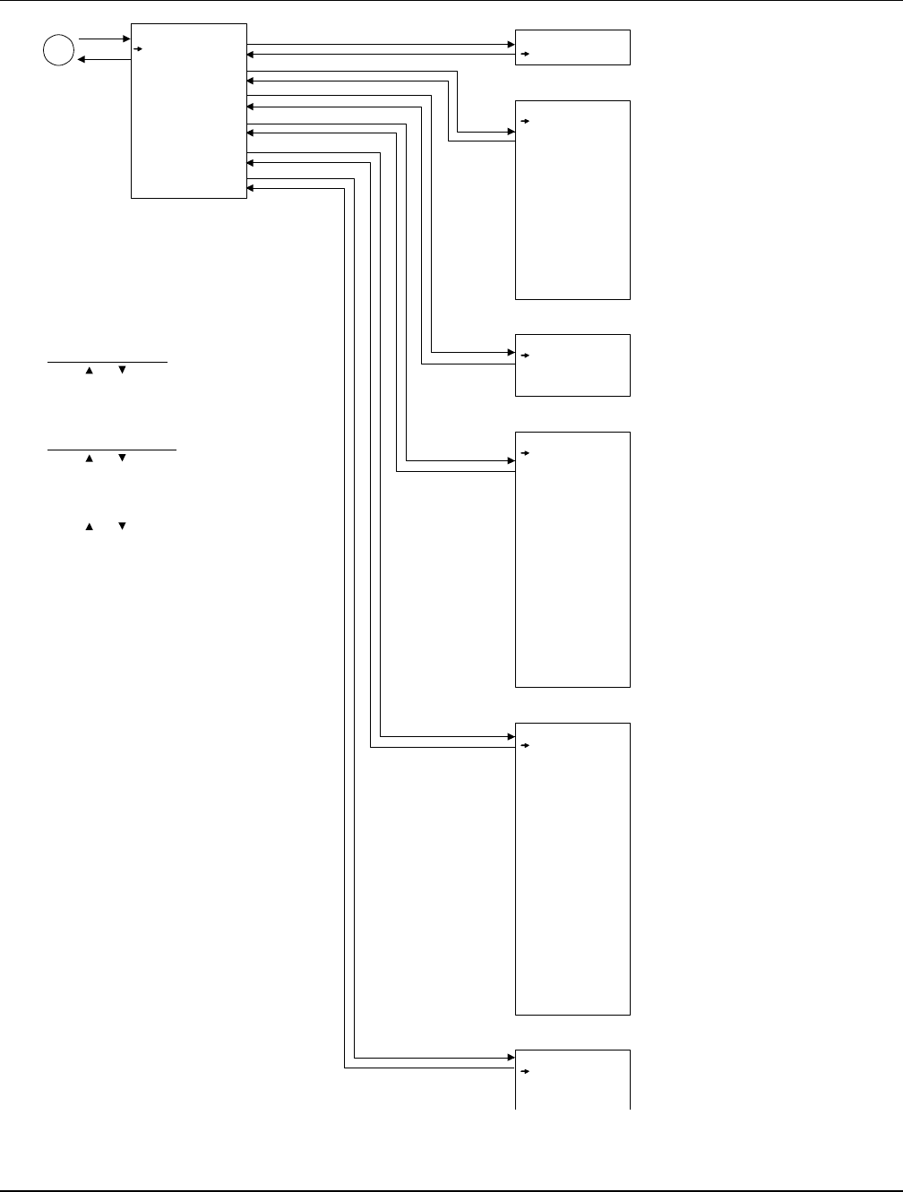
User Instructions UM1M820BNA
Spec No. 1M820BNA (Model M820B) Issue AH, March 4, 2013
Spec No. 1M820DNA (Model M820D)
Chapter 3. Local Display Menus 91
This document is property of Emerson Network Power, Energy Systems, North America, Inc. and contains confidential and proprietary information owned by Emerson Network Power, Energy
Systems, North America, Inc. Any copying, use, or disclosure of it without the written permission of Emerson Network Power, Energy Systems, North America, Inc. is strictly prohibited.
Figure 8 (cont’d from previous page)
Local Menu Flow Diagrams
Quick Setting
Auto/Manual
ECO Mode Set
FLT/EQ Volt
FLT/EQ Set
Temp Comp
RectExpansion
E
ENT
ENT
ENT
ENT
ENT
ENT
ENT
ESC ESC
ESC
ESC
ESC
ESC
ESC
Auto/Man State
Auto (auto / manual)
Float Voltage
54.0 V (42.0-50.0) (21.0-29.0)
EQ Voltage
56.5 V (42.0-58.0) (21.0-29.0)
Rect Expansion
inactive (inactive / primary / secondary)
Address (Slave)
201 (201 / 202 / 203)
Auto/Manual
ECO Mode Set
FLT/EQ Volt
FLT/EQ Set
Temp Comp
Rect Expansion
To Change a Parameter:
Press or to move up and
down list of parameters.
Press ENT to highlight selected parameter.
Press or to change highlighted value.
Press ENT to make the change.
Press ESC to cancel the change.
The parameter values shown in ( ) are the
adjustment range or acceptable values.
Factory default settings are listed in the
ACU+ Configuration Drawing (C-dwg)
furnished with your system.
To Select a Sub-Menu:
Press or to move cursor in
menu screen (selects menu item).
Press ENT to enter selected sub-menu.
ECO Mode
Enabled (disabled / enabled)
Energy Save Pt
45 % (10-90)
Best Oper Point
80 % (30-90)
Fluct Range
10 % (1-50)
Cycle Period
168 hour (1-8760)
Rects ON Time
120 min (0-255)
Turn Off Delay
5 min (1-60)
Auto EQ
No (no / yes)
EQ Start Curr
0.060 C10 (0.040-0.080)
EQ Start Cap
80.0 % (0-99)
EQ Stop Curr
0.010 C10 (0.002-0.020)
EQ Stop Delay
180 min (0-1440)
Maximum EQ Time
1080 min (60-2880)
Cyc EQ
No (no / yes)
Cyc EQ Interval
100 days (2-365)
Cyc EQ Duration
720 min (30-2880)
Temp CompCenter
25.0 deg. C (0.0-40.0)
Temp Comp Coeff
72.0 mV/deg. C (0.0-500.0)
TempComp Sensor
None (None / SMTemp8 T8 / ... / SMTemp8 T1 / ... /
SMTemp1 T8 / ... / SMTemp1 T1 / EIB T2 / EIB T1 /
IB2 T2 / IB2 T1 / System T3 / System T2 / System T1 /
Average SMBRC / Average / Maximum)
Comp Temp High2
60 deg. C (0-100)
Comp Temp High1
50 deg. C (0-100)
Comp Temp Low
-10.0 deg. C (-40 to +100)
Temp Comp Clamp
Enabled (disabled / enabled)
Temp Comp Max V
29.0 (42.0-58.0) (21.0-29.0)
Temp Comp Min V
26.0 (42.0-58.0) (21.0-29.0)
The temperature
monitored by the
Temp. Probe selected
here as the TempComp
Sensor is also displayed
on the Homepage of
the Web Interface as
battery temperature.

UM1M820BNA User Instructions
Issue AH, March 4, 2013 Spec No. 1M820BNA (Model M820B)
Spec No. 1M820DNA (Model M820D)
92 Chapter 3. Local Display Menus
This document is property of Emerson Network Power, Energy Systems, North America, Inc. and contains confidential and proprietary information owned by Emerson Network Power, Energy
Systems, North America, Inc. Any copying, use, or disclosure of it without the written permission of Emerson Network Power, Energy Systems, North America, Inc. is strictly prohibited.
3.3 Description of Local Display (and Web Interface) Menus Line Items
The following are descriptions of the editable parameters presented in the local display menus. Parameter
descriptions can also be used for the WEB Interface menus. Note that the names in the WEB Interface
menus may be longer since the WEB Interface allows more characters to be displayed then the local (LCD)
display.
3.3.1 Settings Menu
Alarm Setting
Alarm Severity Menu
Menu Navigation: Main Menu / Settings / Alarm Setting / Alm Severity
Note: For WEB Interface, menu item is found under Configuration / Signal Information Modification
/ select “Alarm Signal” in “Signal Type” drop-down box.
"Alarm Severity" Parameter Settings:
Use the menus to assign an Alarm Severity Level (none, minor, major, critical) to each
possible alarm.
Alarm Relay Menu
Menu Navigation: Main Menu / Settings / Alarm Setting / Alarm Relay
Note: For WEB Interface, menu item is found under Configuration / Alarm Relays.
"Alarm Relay" Parameter Settings:
Use the menus to assign an alarm relay (for connection of external alarm circuits) to each
possible alarm.
Alarm Param Menu
Menu Navigation: Main Menu / Settings / Alarm Setting / Alarm Param
Note: For WEB Interface; “Block Alarm” menu item is found under Device Information / Power
System / Settings Tab, “Clr Alarm Hist” menu item is found under Maintenance / Clear Data, and
“Alarm Voice” menu item is not available.
"Alarm Param" Parameter Settings:
Alarm Voice: Programs the audible alarm feature.
Off: Disables the audible alarm.
On: When a new alarm occurs, the audible alarm sounds.
Press any key to silence the audible alarm.
3 minutes / 10 minutes / 1 hour / 4 hours: When a new alarm occurs, the audible
alarm sounds. The audible alarm automatically silences after the selected time period.
Block Alarm
Normal: Alarms are processed normally.
Blocked: Forces the alarm relays in the "off" state and blocks alarms from changing
the relay state.
Clr Alm Hist: The only selection for "Clr Alm Hist" is Yes. Once Yes is selected and
confirmed, the alarm history log is cleared.

User Instructions UM1M820BNA
Spec No. 1M820BNA (Model M820B) Issue AH, March 4, 2013
Spec No. 1M820DNA (Model M820D)
Chapter 3. Local Display Menus 93
This document is property of Emerson Network Power, Energy Systems, North America, Inc. and contains confidential and proprietary information owned by Emerson Network Power, Energy
Systems, North America, Inc. Any copying, use, or disclosure of it without the written permission of Emerson Network Power, Energy Systems, North America, Inc. is strictly prohibited.
Power System
General Menu
Menu Navigation: Main Menu / Settings / Power System / General
Note: For WEB Interface; menu items are found under Device Information / Power System /
Settings Tab.
"General" Parameter Settings:
Auto/Man State
Auto: The Controller automatically controls the power system.
Manual: A User can manually change power system control settings. When you return
to Auto Mode, any settings changed in Manual Mode are returned to their previous
setting (setting before being placed in Manual Mode).
Manual Mode Lmt: Time delay before returning to automatic control after being set for
manual control. A "0" setting disables the "Manual Mode Lmt" feature and the Controller
MUST be manually set to Auto control after being set to Manual control.
Mtnc Cycle Time: The maintenance cycle time is the number of days before a
Maintenance Alarm is issued. To reset the maintenance timer and clear the Maintenance
Alarm, clear the Maintenance Run Time (Main Menu / Manual / Power System / Clr
MtncRunTime).
EStop / EShutdown
Disabled: Disables the Emergency Stop and Emergency Shutdown functions.
EStop: Enables the Emergency Stop function.
EShutdown: Enables the Emergency Shutdown function.
Load Curr Alarm: Sets the load current alarm point.
Alarm Blocked
Normal: Alarms are processed normally.
Blocked: Forces the alarm relays in the "off" state and blocks alarms from changing
the relay state.
Rect Expansion
Inactive: Select this option if this is the only ACU+ Controller in the power system.
Primary: Select this option if the power system consists of multiple bays with multiple
ACU+ Controllers, and this ACU+ Controller is to be the Primary Controller. Note that
only one (1) ACU+ Controller can be set as the Primary Controller.
Secondary: Select this option if the power system consists of multiple bays with
multiple ACU+ Controllers, and this ACU+ Controller is to be a Secondary Controller.
_____________________
Up to four (4) ACU+ Controllers can be connected together when a power system requires
a greater number of rectifiers than can be controlled by a single ACU+ Controller. One (1)
Controller is designated as the primary Controller, the others as secondary Controllers.
The rectifiers controlled by the secondary Controllers are designated as RectifierGroup 2
though 4 in the menus.
Primary/Secondary Procedure:
Note: Changing the Rectifier Expansion setting may take more than 3 minutes for the
ACU+ to configure the feature.
1) Connect the ACU+ Controllers in the multiple bays via the RS485 interface.

UM1M820BNA User Instructions
Issue AH, March 4, 2013 Spec No. 1M820BNA (Model M820B)
Spec No. 1M820DNA (Model M820D)
94 Chapter 3. Local Display Menus
This document is property of Emerson Network Power, Energy Systems, North America, Inc. and contains confidential and proprietary information owned by Emerson Network Power, Energy
Systems, North America, Inc. Any copying, use, or disclosure of it without the written permission of Emerson Network Power, Energy Systems, North America, Inc. is strictly prohibited.
2) Set one of the ACU+ Controllers as the Primary Controller via the Rect Expansion
menu item in the Power System "General" Parameters menu.
3) Set all other ACU+ Controllers as Secondary Controllers via the Rect Expansion
menu item in the Power System "General" Parameters menu.
4) Set the Address of the ACU+ Controllers set as Secondary Controllers to 201, 202,
or 203 via the Address (Slave) menu item in the Power System "General"
Parameters menu. Note that each Secondary Controller must be set to a different
address.
_____________________
Address (Slave): Sets the address of an ACU+ Controller set as a Secondary Controller.
Over Voltage 1: Sets the Over Voltage 1 alarm point.
Over Voltage 2: Sets the Over Voltage 2 alarm point.
Under Voltage 1: Sets the Under Voltage 1 alarm point.
Under Voltage 2: Sets the Under Voltage 2 alarm point.
Fail Safe: When enabled, sets the relay designated as the "critical summary" alarm relay
to operate in the "fail safe" mode. In this mode, the relay is energized during normal
operation and de-energized for an alarm condition.
Hybrid Mode: Refer to “1.3.11 Hybrid Control Function” for more information on the Hybrid
Mode.
Disable / Fixed Daily / Capacity: Sets the Hybrid Mode or disables the function.
DG Run Overtemp: Enables or disables diesel generator operation in an over
temperature condition.
DG Run Time: Sets the diesel generator run time.
DG Used: Sets the diesel generator(s) to be utilized.
DI for Grid: Sets the digital input monitoring the grid.
DOD: Sets the Depth of Discharge.
Dsch Duration: Sets the discharge duration.
Start Dsch Time: Sets the start time for discharge.
High Load Set: Sets the high load point.
Equal StartTime: Sets the start time for equalizing.
DG Alarm Delay: Sets the diesel generator alarm delay.
Fail Safe: Tells the Controller the fail safe mode of the relay contacts connected to
start the generator(s) (either normally open or normally close).
Contactor Mode: Enables or disables the Power Split feature (“master control” indicates
the ACU+ system operates normally and “slave control” indicates the ACU+ system is a
slave system of the existing legacy system).
See also “2.7 Power Split Feature”.
Relay Test: Sets the Relay Test feature to Automatic, Individual, or disables the feature.
Relay Test Time: Sets the Relay Test Time for the Automatic Relay Test feature.
HighLoadLevel1: Sets the High Load Level 1 alarm.
HighLoadLevel2: Sets the High Load Level 2 alarm.
DI1 through D18 Alarm State: Sets the alarm state for the digital input (high or low).
Amb Temp Sensor: Sets the temperature sensor which displays the ambient temperature
on the Web Interface’s Homepage. Note that this temperature sensor MUST be set as an

User Instructions UM1M820BNA
Spec No. 1M820BNA (Model M820B) Issue AH, March 4, 2013
Spec No. 1M820DNA (Model M820D)
Chapter 3. Local Display Menus 95
This document is property of Emerson Network Power, Energy Systems, North America, Inc. and contains confidential and proprietary information owned by Emerson Network Power, Energy
Systems, North America, Inc. Any copying, use, or disclosure of it without the written permission of Emerson Network Power, Energy Systems, North America, Inc. is strictly prohibited.
ambient temperature sensor. Select "None", or the temperature probe (SMTemp8 T8 / ... /
SMTemp8 T1 / ... / SMTemp1 T8 / ... / SMTemp1 T1 / EIB T2 / EIB T1 / IB2 T2 / IB2 T1).
You can also select Maximum or Average which takes the maximum or average reading of
the temperature probes (any of SMTemp8 T8 / ... / SMTemp8 T1 / ... / SMTemp1 T8 / ... /
SMTemp1 T1 / EIB T2 / EIB T1 / IB2 T2 / IB2 T1) set as ambient temperature probes.
Amb Temp High2: Allows you to set a high ambient temperature alarm 2 point.
Amb Temp High1: Allows you to set a high ambient temperature alarm 1 point.
Amb Temp Low: Allows you to set a low ambient temperature alarm point.
System Temp1: Not used.
System Temp2: Not used.
System Temp3: Not used.
IB2 Temp1: Sets temperature port 1 on the IB2 board to None, Battery, or Ambient.
IB2 Temp2: Sets temperature port 2 on the IB2 board to None, Battery, or Ambient.
EIB Temp1: Sets temperature port 1 on the EIB board to None, Battery, or Ambient.
EIB Temp2: Sets temperature port 2 on the EIB board to None, Battery, or Ambient.
Note: You can set High2, High1, and Low temperature alarms for each temperature sensor
(from the Web Interface). Note that you cannot set high and low temperature alarms for
individual temperature sensors from the Local Menus. High and low temperature alarm
settings for the temperature sensors set as ambient are found in the Device Information
/ Power System / Settings tab. High and low temperature alarm settings for the probes
set as battery are found in the Device Information / Battery Group / Settings tab.
Power Split Menu
See also “2.7 Power Split Feature”.
Menu Navigation: Main Menu / Settings / Power System / Power Split
Note: For WEB Interface; menu items are found under Device Information / Power System /
Settings Tab.
"Power Split" Parameter Settings:
Slave Curr Lmt: Current limit point for power system designated as the slave system in a
"Power Split" configuration.
Delta Volt: The offset voltage that the power system designated as the slave system in a
"Power Split" configuration is set to. It is suggested to leave this value at the default (0.5
volts).
Proportion Coeff: The proportional coefficient that the power system designated as the
slave system in a "Power Split" configuration is set to. It is suggested to leave this value at
the default (30%).
Integral Time: The integral time that the power system designated as the slave system in
a "Power Split" configuration is set to. It is suggested to leave this value at the default (60
seconds).
Rectifier
All Rect Set Menu
Menu Navigation: Main Menu / Settings / Rectifier / All Rect Set
Note: For WEB Interface; menu items are found under Device Information / Rectifier Group /
Settings Tab.

UM1M820BNA User Instructions
Issue AH, March 4, 2013 Spec No. 1M820BNA (Model M820B)
Spec No. 1M820DNA (Model M820D)
96 Chapter 3. Local Display Menus
This document is property of Emerson Network Power, Energy Systems, North America, Inc. and contains confidential and proprietary information owned by Emerson Network Power, Energy
Systems, North America, Inc. Any copying, use, or disclosure of it without the written permission of Emerson Network Power, Energy Systems, North America, Inc. is strictly prohibited.
"All Rect Set" Parameter Settings:
HVSD: Enables or disables the High Voltage Shutdown feature for all rectifiers.
HVSD Limit: Sets the High Voltage Shutdown point for all rectifiers.
Restart on HVSD: Enables or disables the High Voltage Shutdown Restart feature for all
rectifiers.
HVSD Restart T: When the High Voltage Shutdown Restart feature is enabled and the
output exceeds the high voltage limit, the rectifiers restart after this time period expires.
Start Interval: Sets the sequence start interval (time period between starting each rectifier
in the system).
Walk-In: Enables or disables the start-up walk-in feature for all rectifiers.
Walk-In Time: Sets the walk-in time period for all rectifiers.
Turn On ACOverV: Enables or disables the "Turn On AC Over Voltage" feature. When the
system is operating on “week” grid input power (i.e. diesel generator), the input voltage
may have a very high peak voltage which may cause a rectifier not to turn on. If “Turn On
AC Over Voltage" feature is enabled, the rectifier is forced to turn on.
ECO Mode: Enables or disables the Energy Optimization feature for all rectifiers. When
enabled, the following parameters can be set.
Best Oper Point: Percent of full load capacity that the rectifiers operate under in the
Energy Optimization mode.
Fluct Range: If load fluctuation is less than this value, rectifiers are not turned on or off
for Energy Optimization.
Energy Save Pt: Energy Optimization is disabled if the load is greater than this setting.
Cycle Period: This is the time period that rectifiers are turned on and off to maintain an
equal operating time for all rectifiers in the system.
Rects ON Time: Time all rectifiers are turned on at End of Cycle.
Turn Off Delay: When the Energy Optimization feature determines a rectifier can be
switched off, this is the time delay before the rectifier is switched off.
Input Curr Lmt: Sets the Input Current Limit point for all rectifiers.
MixHE Power: Allows the system to use rectifiers of different output capacity. When set to
derated power, the output capacity of the higher capacity rectifiers are set to the capacity of
the lowest.
DG Pwr Lmt: Enables or disables the Diesel Power Limit feature. This feature limits
rectifier output power to a percentage of maximum when AC input is supplied by a
diesel-alternator set.
Diesel DI Input: Designates which digital input controls operation of the Diesel Power
Limit feature.
DG Pwr Lmt Pt: Sets, as a percentage, the maximum output power at which rectifiers
can operate when: 1. the Diesel Power Limit feature is enabled and 2. a digital input
signal is received from the connected diesel-alternator set.
Current Limit: Enables or disables output current limit.
Current Limit Pt: Sets the output current limit point.
Rect #1 Menu
Menu Navigation: Main Menu / Settings / Rectifier / Rect #1
Note: For WEB Interface; menu items are found under Device Information / Rectifier Group /
Rectifier #1 / Settings Tab.

User Instructions UM1M820BNA
Spec No. 1M820BNA (Model M820B) Issue AH, March 4, 2013
Spec No. 1M820DNA (Model M820D)
Chapter 3. Local Display Menus 97
This document is property of Emerson Network Power, Energy Systems, North America, Inc. and contains confidential and proprietary information owned by Emerson Network Power, Energy
Systems, North America, Inc. Any copying, use, or disclosure of it without the written permission of Emerson Network Power, Energy Systems, North America, Inc. is strictly prohibited.
" Rect #1" Parameter Settings:
Rectifier ID: Sets the rectifier position in the system.
Rect Phase: Indicates the phase connected to the rectifier input.
Battery
Basic Menu
Menu Navigation: Main Menu / Settings / Battery / Basic
Note: For WEB Interface; menu items are found under Device Information / Battery Group /
Settings Tab.
"Basic" Parameter Settings:
Num Batt Shunts: Sets the number of battery shunts in the system.
Calc Batt Curr: Selects whether or not the ACU+ calculates the battery current in the case
of no battery shunt (load shunt required).
Low Capacity Pt: Battery low capacity alarm set point.
Current Limited: Enables or disables battery charge current limit.
BTRM TempSensor: Sets the BTRM (Battery Thermal Runaway Management)
temperature sensor. Note that this temperature sensor MUST be set as a battery
temperature sensor. Select "None", or the temperature probe (SMTemp8 T8 / ... /
SMTemp8 T1 / ... / SMTemp1 T8 / ... / SMTemp1 T1 / EIB T2 / EIB T1 / IB2 T2 / IB2 T1).
You can also select Maximum or Average which takes the maximum or average reading of
the temperature probes (any of SMTemp8 T8 / ... / SMTemp8 T1 / ... / SMTemp1 T8 / ... /
SMTemp1 T1 / EIB T2 / EIB T1 / IB2 T2 / IB2 T1) set as battery temperature probes. When
used with an SM-BRC, you can select to average the SM-BRC temperature probe
readings.
Note: The BTRM sensor is the sensor which is used for the High Temperature Disconnect
(HTD) Feature.
BTRM Temp High2: Allows you to set a high BTRM temperature alarm 2 point. If battery
temperature exceeds the “BTRM Temp High2” setting, system voltage is lowered to the
“BTRM Voltage” setting (if BTRM Action is enabled).
BTRM Temp High1: Allows you to set a high BTRM temperature alarm 1 point.
BTRM Action
Disabled: Disables the Battery Thermal Runaway Management feature.
Lower Voltage: Sets the Battery Thermal Runaway Management feature to reducing
the output voltage when battery temperature exceeds the BTRM Temp setting.
BTRM Voltage: Voltage that the system is set to when battery temperature
exceeds the “BTRM Temp High2” setting.
ABCL Point: The ABCL (Active Battery Charge Current Limit) point is the maximum Li-Ion
battery charging current setting.
Charge Menu
Menu Navigation: Main Menu / Settings / Battery / Charge
Note: For WEB Interface; menu items are found under Device Information / Battery Group /
Settings Tab.
"Charge" Parameter Settings:
Float Voltage: Float Charge output voltage setting.
EQ Voltage: Equalize Charge output voltage setting.

UM1M820BNA User Instructions
Issue AH, March 4, 2013 Spec No. 1M820BNA (Model M820B)
Spec No. 1M820DNA (Model M820D)
98 Chapter 3. Local Display Menus
This document is property of Emerson Network Power, Energy Systems, North America, Inc. and contains confidential and proprietary information owned by Emerson Network Power, Energy
Systems, North America, Inc. Any copying, use, or disclosure of it without the written permission of Emerson Network Power, Energy Systems, North America, Inc. is strictly prohibited.
Batt Curr Limit: Maximum battery charging current setting. For example, a value of
0.150C10 means that the charging current is limited to 15% of the battery’s nominal
capacity.
Over Curr Lmt: Battery over current alarm setting. For example, a value of 0.300C10
means that when the charging current reaches 30% of the battery’s nominal capacity, an
alarm will be extended.
Auto EQ: Enables or disables the Automatic Equalize Charge feature. When enabled, the
following parameters can be set.
EQ Start Curr: The system is transferred to Equalize Charge mode when battery
charge current increases to this setting. For example, a value of 0.060C10 means that
an Automatic Equalize is started if the battery charge current is greater than 6% of the
battery’s nominal capacity.
EQ Start Cap: The system is transferred to Equalize Charge mode when remaining
battery capacity decreases to this setting.
EQ Stop Curr: When in Equalize Charge mode and the battery charge current
decreases below this setting for the "EQ Stop Delay" time period, the system is
transferred to Float Charge mode. For example, a value of 0.010C10 means that when
the charging current is less than 1% of the battery’s nominal capacity, the system
returns to the Float mode.
EQ Stop Delay: See "EQ Stop Curr" above.
Note: If the power system has been automatically placed in Equalize mode, disabling
Auto EQ will not return the system to Float mode until the current Equalize cycle is
completed. To return immediately to Float mode, navigate as follows: Main Menu /
Manual / Batt Group / “EQ/FLT Control”, and select Float Charge.
Maximum EQ Time: This is the maximum duration, in minutes, that an Automatic Equalize
Charge will last regardless of the other settings.
Cyc EQ: Enables or disables cyclic (scheduled) Equalize charging. When enabled, the
following parameters can be set.
Cyc EQ Interval: Cyclic (scheduled) Equalize charging interval.
Cyc EQ Duration: Cyclic (scheduled) Equalize charging duration.
Test Menu
Menu Navigation: Main Menu / Settings / Battery / Test
Note: For WEB Interface; menu items are found under Device Information / Battery Group /
Settings Tab.
"Test" Parameter Settings:
Test Volt Lmt: System output voltage setting during a battery discharge test.
Test End Volt: This is the “end of test voltage level” for battery discharge tests. A battery
discharge test will end if battery voltage decreases to this setting.
End Test Time: This is the "end of test time period” for battery discharge tests. A battery
discharge test will end if this time period is exceeded.
EndTestCapacity: This is the "end of test remaining battery capacity” for battery discharge
tests. A battery discharge test will end if remaining battery capacity decreases to this
setting. For example, a value of 0.700C10 means that when the discharging current
reaches 70% of the battery’s nominal capacity, the battery test is ended.
RecordThreshold: This setting indicates the interval battery voltage is recorded during a
battery discharge test.

User Instructions UM1M820BNA
Spec No. 1M820BNA (Model M820B) Issue AH, March 4, 2013
Spec No. 1M820DNA (Model M820D)
Chapter 3. Local Display Menus 99
This document is property of Emerson Network Power, Energy Systems, North America, Inc. and contains confidential and proprietary information owned by Emerson Network Power, Energy
Systems, North America, Inc. Any copying, use, or disclosure of it without the written permission of Emerson Network Power, Energy Systems, North America, Inc. is strictly prohibited.
AC Fail Test: Enables or disables starting a battery discharge test during an AC input
failure condition.
Planned Tests: Number of planned battery discharge test per year. A "0" setting disables
the planned test feature.
Test 1 (M-D Hr): Setting for when planned battery discharge test #1 occurs. Note that
there can be up to (12) battery discharge tests per year.
Const Curr Test: Enables or disables a Constant Current Battery Discharge Test. During
this test, the Controller automatically adjusts the rectifiers output voltage to maintain the
battery discharge current at a preset value "ConstCurrT Curr".
ConstCurrT Curr: Constant current setting for a Constant Current Battery Discharge
Test.
Short Test: Enables or disables a Short Battery Discharge Test. A Short Battery
Discharge Test is a short duration battery discharge test used to verify that parallel
batteries are discharging equally. If the discharge current difference between the two
batteries exceeds a preset value, an alarm is generated.
Note: This test requires a system with two battery shunts.
ShortTest Cycle: Short Battery Discharge Test interval.
Short Test Time: Short Battery Discharge Test duration.
Max Diff Curr: An alarm is generated if the maximum difference between discharge
currents of the two batteries exceeds this limit.
BattTestLowCap: If remaining battery capacity is less than this value, a battery discharge
test will not be started.
Temp Comp Menu
Menu Navigation: Main Menu / Settings / Battery / Temp Comp
Note: For WEB Interface; menu items are found under Device Information / Battery Group /
Settings Tab.
"Temp Comp" Parameter Settings:
Temp CompCenter: Sets the temperature at which the system operates at normal voltage
levels.
Temp Comp Coeff: Sets the temperature compensation slope or rate of change per °C
above or below the "Temp Comp" setting. This value is expressed in millivolt per °C per
string (mV/°C/str). For example, for a rate of change of 72 mV/°C/str in a 24-cell 48V
nominal battery string, the rate of change is 3 mV per cell.
TempComp Sensor: Select "None" for no temperature compensation, or the temperature
probe (SMTemp8 T8 / ... / SMTemp8 T1 / ... / SMTemp1 T8 / ... / SMTemp1 T1 / EIB T2 /
EIB T1 / IB2 T2 / IB2 T1) sensing battery temperature for temperature compensation. You
can also select Maximum or Average which takes the maximum or average reading of the
temperature probes (any of SMTemp8 T8 / ... / SMTemp8 T1 / ... / SMTemp1 T8 / ... /
SMTemp1 T1 / EIB T2 / EIB T1 / IB2 T2 / IB2 T1) set as battery temperature probes. When
used with an SM-BRC, you can select to average the SM-BRC temperature probe
readings.
Note: The temperature compensation sensor is also the sensor which displays the battery
temperature on the Web Interface’s Homepage.
Comp Temp High2: Allows you to set a high compensation temperature alarm 2 point.
Comp Temp High1: Allows you to set a high compensation temperature alarm 1 point.
Comp Temp Low: Allows you to set a low compensation temperature alarm point.

UM1M820BNA User Instructions
Issue AH, March 4, 2013 Spec No. 1M820BNA (Model M820B)
Spec No. 1M820DNA (Model M820D)
100 Chapter 3. Local Display Menus
This document is property of Emerson Network Power, Energy Systems, North America, Inc. and contains confidential and proprietary information owned by Emerson Network Power, Energy
Systems, North America, Inc. Any copying, use, or disclosure of it without the written permission of Emerson Network Power, Energy Systems, North America, Inc. is strictly prohibited.
Temp Comp Clamp: Enables or disables the temperature compensation voltage clamp
feature.
Temp Comp Max V: Upper voltage limit where battery temperature compensation clamps
the voltage.
Temp Comp Min V: Lower voltage limit where battery temperature compensation clamps
the voltage.
Capacity Menu
Menu Navigation: Main Menu / Settings / Battery / Capacity
Note: For WEB Interface; menu items are found under Device Information / Battery Group /
Settings Tab.
"Capacity" Parameter Settings:
Charging Eff: Value used to calculate remaining capacity of the battery.
Time 0.1C10: Discharge time with a discharge current of 0.1C10.
Time 0.2C10: Discharge time with a discharge current of 0.2C10.
Time 0.3C10: Discharge time with a discharge current of 0.3C10.
Time 0.4C10: Discharge time with a discharge current of 0.4C10.
Time 0.5C10: Discharge time with a discharge current of 0.5C10.
Time 0.6C10: Discharge time with a discharge current of 0.6C10.
Time 0.7C10: Discharge time with a discharge current of 0.7C10.
Time 0.8C10: Discharge time with a discharge current of 0.8C10.
Time 0.9C10: Discharge time with a discharge current of 0.9C10.
Time 1.0C10: Discharge time with a discharge current of 1.0C10.
Battery # Menu
Menu Navigation: Main Menu / Settings / Battery / Battery #
Note: For WEB Interface; menu items are found under Device Information / Battery Group / Battery
# / Settings Tab.
"Battery #" Parameter Settings:
Rated Capacity: Enter the battery string’s rated capacity.
Shunt Current: Enter the battery string’s shunt current rating.
Shunt Voltage: Enter the battery string’s shunt voltage rating.
BattFuseUnit
BattFuseUnit Menu
Menu Navigation: Main Menu / Settings / BattFuseUnit
Note: For WEB Interface; menu items are found under Device Information / Battery Fuse Group /
Battery Fuse Unit / Settings Tab.
"BattFuseUnit" Parameter Settings:
Num of Bat Fuse: Designates the number of battery fuses in the system.
DC
DC Menu
Menu Navigation: Main Menu / Settings / DC
Note: For WEB Interface; menu items are found under Device Information / DC / Settings Tab.

User Instructions UM1M820BNA
Spec No. 1M820BNA (Model M820B) Issue AH, March 4, 2013
Spec No. 1M820DNA (Model M820D)
Chapter 3. Local Display Menus 101
This document is property of Emerson Network Power, Energy Systems, North America, Inc. and contains confidential and proprietary information owned by Emerson Network Power, Energy
Systems, North America, Inc. Any copying, use, or disclosure of it without the written permission of Emerson Network Power, Energy Systems, North America, Inc. is strictly prohibited.
"DC" Parameter Settings:
Shunt Current: Enter the load shunt’s current rating.
Shunt Voltage: Enter the load shunt’s voltage rating.
LoadShuntExist: Select whether a load shunt exists or not.
LVD
LVD Group Menu
Menu Navigation: Main Menu / Settings / LVD / LVD Group
Note: For WEB Interface; menu items are found under Device Information / LVD Group / Settings
Tab.
Note: This feature requires a BTRM sensor. The BTRM sensor is the sensor which is used for the
High Temperature Disconnect (HTD) Feature.
"LVD Group" Parameter Settings:
HTD Recon Point: Sets temperature at which a reconnect will occur following a High
Temperature Disconnect.
HTD Point: Sets high temperature limit at which LVD1 and/or LVD2 contactors will open
(disconnect) if the HTD1 and/or HTD2 features are enabled. If this temperature is reached,
a disconnect occurs regardless of voltage.
LVD Unit Menu
Menu Navigation: Main Menu / Settings / LVD / LVD Unit
Note: For WEB Interface; menu items are found under Device Information / LVD Group / LVD Unit
/ Settings Tab.
"LVD Unit" Parameter Settings:
LVD1: Enables or disables LVD1.
LVD1 Mode: Sets LVD1 to disconnect on a voltage or time setpoint.
LVD1 Volt: LVD1 low voltage disconnect setting (when LVD set for voltage).
LVD1 Recon Volt: LVD1 reconnect setting (when LVD set for voltage).
LVD1 ReconDelay: Delay time period until LVD1 reconnects once voltage recovers
(when LVD set for voltage).
LVD1 Time: The time period before LVD1 disconnection once an AC fail condition
occurs (when LVD set for time).
LVD1 Dependency: Select if LVD1 can disconnect only if LVD2 has disconnected, or
none.
LVD2: Enables or disables LVD2.
LVD2 Mode: Sets LVD2 to disconnect on a voltage or time setpoint.
LVD2 Volt: LVD2 low voltage disconnect setting (when LVD set for voltage).
LVD2 Recon Volt: LVD2 reconnect setting (when LVD set for voltage).
LVD2 ReconDelay: Delay time period until LVD2 reconnects once voltage recovers
(when LVD set for voltage).
LVD2 Time: The time period before LVD2 disconnection once an AC fail condition
occurs (when LVD set for time).
LVD2 Dependency: Select if LVD2 can disconnect only if LVD1 has disconnected, or
none.

UM1M820BNA User Instructions
Issue AH, March 4, 2013 Spec No. 1M820BNA (Model M820B)
Spec No. 1M820DNA (Model M820D)
102 Chapter 3. Local Display Menus
This document is property of Emerson Network Power, Energy Systems, North America, Inc. and contains confidential and proprietary information owned by Emerson Network Power, Energy
Systems, North America, Inc. Any copying, use, or disclosure of it without the written permission of Emerson Network Power, Energy Systems, North America, Inc. is strictly prohibited.
HTD1: Enables or disables the High Temperature 1 Disconnect feature. This feature
causes LVD1 contactors to open (disconnect) if a high temperature event occurs. (See
HTD selections in the "LVD Group" Parameter Settings.)
HTD2: Enables or disables the High Temperature 2 Disconnect feature. This feature
causes LVD2 contactors to open (disconnect) if a high temperature event occurs. (See
HTD selections in the "LVD Group" Parameter Settings.)
LVD Type: Select the type of LVD Contactor. This setting should not be changed.
SMDU 1 LVD Menu
Menu Navigation: Main Menu / Settings / LVD / SMDU 1 LVD
Note: For WEB Interface; menu items are found under Device Information / LVD Group / SMDU 1
LVD / Settings Tab.
"SMDU 1 LVD" Parameter Settings:
LVD 1: Enables or disables LVD1.
LVD 1 Mode: Sets LVD1 to disconnect on a voltage or time setpoint.
LVD 1 Voltage: LVD1 low voltage disconnect setting (when LVD set for voltage).
LVD1 Recon Volt: LVD1 reconnect setting (when LVD set for voltage).
LVD1 ReconDelay: Delay time period until LVD1 reconnects once voltage recovers
(when LVD set for voltage).
LVD 1 Time: The time period before LVD1 disconnection once an AC fail condition
occurs (when LVD set for time).
LVD1 Dependency: Select if LVD1 can disconnect only if LVD2 has disconnected, or
none.
LVD 2: Enables or disables LVD2.
LVD 2 Mode: Sets LVD2 to disconnect on a voltage or time setpoint.
LVD 2 Voltage: LVD2 low voltage disconnect setting (when LVD set for voltage).
LVD2 Recon Volt: LVD2 reconnect setting (when LVD set for voltage).
LVD2 ReconDelay: Delay time period until LVD2 reconnects once voltage recovers
(when LVD set for voltage).
LVD 2 Time: The time period before LVD2 disconnection once an AC fail condition
occurs (when LVD set for time).
LVD2 Dependency: Select if LVD2 can disconnect only if LVD1 has disconnected, or
none.
HTD 1: Enables or disables the High Temperature 1 Disconnect feature. This feature
causes LVD1 contactors to open (disconnect) if a high temperature event occurs. (See
HTD selections in the "LVD Group" Parameter Settings.)
HTD 2: Enables or disables the High Temperature 2 Disconnect feature. This feature
causes LVD2 contactors to open (disconnect) if a high temperature event occurs. (See
HTD selections in the "LVD Group" Parameter Settings.)
AC
Rect AC Menu
Menu Navigation: Main Menu / Settings / AC / Rect AC
Note: For WEB Interface; menu items are found under Device Information / AC Group / Rect AC /
Settings Tab.

User Instructions UM1M820BNA
Spec No. 1M820BNA (Model M820B) Issue AH, March 4, 2013
Spec No. 1M820DNA (Model M820D)
Chapter 3. Local Display Menus 103
This document is property of Emerson Network Power, Energy Systems, North America, Inc. and contains confidential and proprietary information owned by Emerson Network Power, Energy
Systems, North America, Inc. Any copying, use, or disclosure of it without the written permission of Emerson Network Power, Energy Systems, North America, Inc. is strictly prohibited.
"Rect AC" Parameter Settings:
Nominal PH-Volt: Enter the nominal line-to-neutral voltage (single phase rectifier) or
nominal line-to-line voltage (three phase rectifier).
Mains Fail Alm1: Sets the Mains Fail Alarm 1 value (percent of nominal).
Mains Fail Alm2: Sets the Mains Fail Alarm 2 value (percent of nominal).
Corresponding Alarms:
Phase A Voltage Low 1 (Nominal Minus "Mains Fail Alarm 1 Percent of Nominal)
Phase A Voltage Low 2 (Nominal Minus " Mains Fail Alarm 2 Percent of Nominal)
Phase A Voltage High 1 (Nominal Plus " Mains Fail Alarm 1 Percent of Nominal)
Phase A Voltage High 2 (Nominal Plus "V Mains Fail Alarm 2 Percent of Nominal)
Phase A used in the example above, Phase B and Phase C are similar.
EIB
EIB 1 Menu
Menu Navigation: Main Menu / Settings / EIB / EIB 1
Note: For WEB Interface; menu items are found under Device Information / EIB Group / EIB 1 /
Settings Tab.
"EIB 1" Parameter Settings:
Shunt 1 Current: Enter the shunt 1 current rating.
Shunt 1 Voltage: Enter the shunt 1 voltage rating.
Shunt 2 Current: Enter the shunt 2 current rating.
Shunt 2 Voltage: Enter the shunt 2 voltage rating.
Shunt 3 Current: Enter the shunt 3 current rating.
Shunt 3 Voltage: Enter the shunt 3 voltage rating.
Num Batt Shunts: Enter the number of battery shunts connected to the EIB assembly.
Num Load Shunts: Enter the number of load shunts connected to the EIB assembly.
Voltage Type: The EIB assembly provides a total of eight (8) DC voltage inputs for battery
block monitoring. 24 (Block 2) selects the EIB to monitor up to four (4) 24V battery strings
with two (2) 12V blocks per string. 48 (Block 4) selects the EIB to monitor up to two (2) 48V
battery strings with four (4) 12V blocks per string. Midpoint selects the EIB to monitor the
midpoint voltage of up to eight (8) battery strings for either 24V or 48V systems.
Blk V Diff(12V): This menu item appears if “24 (Block 2)” or “48 (Block 4)” is selected
above. The “BlockVDiff(12V)” setting above selects the alarm threshold for battery
block monitoring. The ACU+ issues an alarm when any block voltage of any battery
string has an abnormal value. The alarm is issued when the difference between any
block voltage and a reference voltage is greater than the value of the block voltage
difference setting.
Blk V Diff(Mid): This menu item appears if “Midpoint” is selected above. The
“BlockVDiff(Mid)” setting above selects the alarm threshold for battery midpoint
monitoring. The ACU+ issues an alarm when any battery midpoint voltage of any
battery string has an abnormal value. The alarm is issued when the difference between
any battery midpoint voltage and a reference voltage is greater than the value of the
block voltage difference setting.
Block In-Use: Number of 12V battery blocks being used.

UM1M820BNA User Instructions
Issue AH, March 4, 2013 Spec No. 1M820BNA (Model M820B)
Spec No. 1M820DNA (Model M820D)
104 Chapter 3. Local Display Menus
This document is property of Emerson Network Power, Energy Systems, North America, Inc. and contains confidential and proprietary information owned by Emerson Network Power, Energy
Systems, North America, Inc. Any copying, use, or disclosure of it without the written permission of Emerson Network Power, Energy Systems, North America, Inc. is strictly prohibited.
SMDU
SMDU 1 Menu
Menu Navigation: Main Menu / Settings / SMDU / SMDU 1
Note: For WEB Interface; menu items are found under Device Information / SMDU Group / SMDU 1
/ Settings Tab.
"SMDU 1" Parameter Settings:
Shunt 1 Voltage: Enter the shunt 1 voltage rating.
Shunt 1 Current: Enter the shunt 1 current rating.
Shunt 2 Voltage: Enter the shunt 2 voltage rating.
Shunt 2 Current: Enter the shunt 2 current rating.
Shunt 3 Voltage: Enter the shunt 3 voltage rating.
Shunt 3 Current: Enter the shunt 3 current rating.
Shunt 4 Voltage: Enter the shunt 4 voltage rating.
Shunt 4 Current: Enter the shunt 4 current rating.
Shunt 5 Voltage: Enter the shunt 5 voltage rating.
Shunt 5 Current: Enter the shunt 5 current rating.
Converter
All Conv Set Menu
Menu Navigation: Main Menu / Settings / Converter / All Conv Set
Note: For WEB Interface; menu items are found under Device Information / Converter Group /
Settings Tab.
"All Conv Set" Parameter Settings:
Output Voltage: Sets the output voltage for all converters.
Under Voltage: Sets the Under Voltage alarm point.
Over Voltage: Sets the Over Voltage alarm point.
Over Current: Sets the Over Current alarm point.
HVSD: Enables or disables the High Voltage Shutdown feature for all converters.
HVSD Limit: Sets the High Voltage Shutdown point for all converters.
Current Limit: Enables or disables output current limit.
Current Limit Pt: Sets the output current limit point.
Conv #1 Menu
Menu Navigation: Main Menu / Settings / Converter / Conv #1
Note: For WEB Interface; menu items are found under Device Information / Converter Group /
Converter #1 / Settings Tab.
" Conv #1" Parameter Settings:
Set Conv ID: Sets the converter position in the system.

User Instructions UM1M820BNA
Spec No. 1M820BNA (Model M820B) Issue AH, March 4, 2013
Spec No. 1M820DNA (Model M820D)
Chapter 3. Local Display Menus 105
This document is property of Emerson Network Power, Energy Systems, North America, Inc. and contains confidential and proprietary information owned by Emerson Network Power, Energy
Systems, North America, Inc. Any copying, use, or disclosure of it without the written permission of Emerson Network Power, Energy Systems, North America, Inc. is strictly prohibited.
SMTemp
SMTemp # Menu
Menu Navigation: Main Menu / Settings / SMTemp / SMTemp #
Note: For WEB Interface; menu items are found under Device Information / SM Temp Group / SM
Temp # / Setting Tab.
"SMTemp #" Parameter Settings:
T# Assign Equip: Sets temperature port # on the SM-Temp # module to None, Battery, or
Ambient.
Note: You can set High2, High1, and Low temperature alarms for each temperature sensor
(from the Web Interface). Note that you cannot set high and low temperature alarms for
individual temperature sensors from the Local Menus. High and low temperature alarm
settings for the temperature sensors set as ambient are found in the Device Information
/ Power System / Settings tab. High and low temperature alarm settings for the probes
set as battery are found in the Device Information / Battery Group / Settings tab.
Communication
Communication Menu
Menu Navigation: Main Menu / Settings / Communication
Note: For WEB Interface; menu items are found under Maintenance / Network Configuration.
"Communication" Parameter Settings:
DHCP: The DHCP function allows the Controller to acquire an IP address automatically.
This function can only be enabled or disabled via the local LCD display and keypad. If this
function is enabled and the acquisition of an IP address fails, an alarm is generated. If the
acquisition of an IP address is successful, you need to record the IP address automatically
acquired by the Controller to access the Controller via the Web Interface.
IP Address: Sets the Controller's IP address.
Enter the address in the format nnn.nnn.nnn.nnn, where 0 ≤ nnn ≤ 255.
The address must be a valid address and must not be 255.255.255.255.
Subnet Mask: Sets the Controller's network netmask.
Enter the address in the format nnn.nnn.nnn.nnn, where 0 ≤ nnn ≤ 255.
Default Gateway: Sets the Controller's gateway address.
Enter the address in the format nnn.nnn.nnn.nnn, where 0 ≤ nnn ≤ 255.
This is the address of the gateway of the network on which the Controller resides.
The address must be a valid address and must not be 255.255.255.255.
Controller
Controller Menu
Menu Navigation: Main Menu / Settings / Controller
Note: For WEB Interface; menu items are found under the Maintenance and Configuration menus.
"Controller" Parameter Settings:
Language: Select the language the menus are displayed in.
Date: Sets the date.
Time: Sets the time.
Keypad Voice: Sets the keypad sound on or off.
Reload Config: Reloads the configuration that resides in memory (restores factory
defaults).

UM1M820BNA User Instructions
Issue AH, March 4, 2013 Spec No. 1M820BNA (Model M820B)
Spec No. 1M820DNA (Model M820D)
106 Chapter 3. Local Display Menus
This document is property of Emerson Network Power, Energy Systems, North America, Inc. and contains confidential and proprietary information owned by Emerson Network Power, Energy
Systems, North America, Inc. Any copying, use, or disclosure of it without the written permission of Emerson Network Power, Energy Systems, North America, Inc. is strictly prohibited.
Download Config: Downloads a configuration file into the Controller.
Auto Config: Auto configures the Controller for the devices connected to it.
3.3.2 ECO Mode (Energy Optimization) Menu
Menu Navigation: Main Menu / ECO Mode
Note: For WEB Interface; menu items are found under Quick Settings / ECO Mode Setting.
"ECO Mode" Parameter Settings:
ECO Mode: Enables or disables the Energy Optimization Mode feature for all rectifiers.
When enabled, the following parameters can be set.
Best Oper Point: Percent of full load capacity that the rectifiers operate under in the
Energy Optimization mode.
Energy Save Pt: Energy Optimization is disabled if the load is greater than this setting.
Fluct Range: If load fluctuation is less than this value, rectifiers are not turned on or off
for Energy Optimization.
Cycle Period: This is the time period that rectifiers are turned on and off to maintain an
equal operating time for all rectifiers in the system.
Rects ON Time: Time all rectifiers are turned on at End of Cycle.
Turn Off Delay: When the Energy Optimization feature determines a rectifier can be
switched off, this is the time delay before the rectifier is switched off.
3.3.3 Manual Menu
Note: Menu items shown with an asterisk (*) can be changed while in Auto Mode. Before any other
settings in this section can be changed, you must first place the ACU+ in the Manual mode. See
"’Man/Auto Set Parameter Settings" for a procedure.
Items that can only be changed in the Manual mode will revert to their previous settings when the
Controller is returned to the Auto mode.
Man/Auto Set
Man/Auto Set Menu
Menu Navigation: Main Menu / Manual / "Man/Auto Set"
Note: For WEB Interface; menu items are found under Quick Settings / “Auto/Manual Setting”.
"Man/Auto Set" Parameter Settings:
Auto/Man State*
Auto: The Controller automatically controls the power system.
Manual: A User can manually change certain power system control settings via the
following menus. (See Note above.) This provides a convenient means of making
temporary adjustment changes for testing purposes.
Power System
Power System Menu
Menu Navigation: Main Menu / Manual / Power System
Note: For WEB Interface; menu items are found under Device Information / Power System / select
the Control tab.
"Power System" Parameter Settings:
Relay Output 1 through 8: Temporarily sets the relay to active or not active. Setting
reverts to original when Controller is returned to the Auto mode.

User Instructions UM1M820BNA
Spec No. 1M820BNA (Model M820B) Issue AH, March 4, 2013
Spec No. 1M820DNA (Model M820D)
Chapter 3. Local Display Menus 107
This document is property of Emerson Network Power, Energy Systems, North America, Inc. and contains confidential and proprietary information owned by Emerson Network Power, Energy
Systems, North America, Inc. Any copying, use, or disclosure of it without the written permission of Emerson Network Power, Energy Systems, North America, Inc. is strictly prohibited.
Clr MtncRunTime*: The only selection for "Clear Maintenance Run Time" is Yes. Once
Yes is selected and confirmed, the Power System’s Maintenance Run Time log is cleared.
Rectifier
All Rect Ctrl Menu
Menu Navigation: Main Menu / Manual / Rectifier / All Rect Ctrl
Note: For WEB Interface; menu items are found under Device Information / Rectifier Group / select
the Control tab.
"All Rect Ctrl" Parameter Settings:
Rectifier Trim: Temporarily sets the output voltage for all rectifiers. Voltage can be
increased or decreased from the existing Float Charge or Equalize Charge setting,
depending which mode the Controller was in when set to "Manual". Setting reverts to
original when Controller is returned to the Auto mode.
DC On/Off Ctrl: Temporarily turns the DC output on or off for all rectifiers. Setting returns
to original when Controller is returned to the Auto mode.
AC On/Off Ctrl: Temporarily turns the AC input on or off for all rectifiers. Setting returns to
original when Controller is returned to the Auto mode.
Rect LED Ctrl: Temporarily sets whether or not a rectifier’s local power indicator blinks
when the Controller is communicating with the rectifier. Setting returns to original when
Controller is returned to the Auto mode.
Fan Speed Ctrl: Temporarily sets the fan speed for all rectifiers. Setting returns to original
when Controller is returned to the Auto mode.
Confirm ID/PH*: Confirms the position and input phase for all rectifiers.
Clear Rect Lost*: Clears a rectifier lost alarm.
Reset Cycle Alm*: Clears a rectifier oscillator alarm.
Clear Comm Fail*: Clears a rectifier communication fail alarm.
Rect #1 Menu
Menu Navigation: Main Menu / Manual / Rectifier / Rect #1
Note: For WEB Interface; menu items are found under Device Information / Rectifier Group /
Rectifier #1 / select the Control tab.
"Rect #1" Parameter Settings:
DC On/Off Ctrl: Temporarily turns the rectifier’s DC output on or off. Setting returns to
original when Controller is returned to the Auto mode.
AC On/Off Ctrl: Temporarily turns the rectifier’s AC input on or off. Setting returns to
original when Controller is returned to the Auto mode.
LED Control: Temporarily sets whether or not the rectifier’s local power indicator blinks
when the Controller is communicating with the rectifier. Setting returns to original when
Controller is returned to the Auto mode.
Rectifier Reset*: Resets the rectifier.
Batt Group
Batt Group Menu
Menu Navigation: Main Menu / Manual / Batt Group
Note: For WEB Interface; menu items are found under Device Information / Battery Group / select
the Control tab.

UM1M820BNA User Instructions
Issue AH, March 4, 2013 Spec No. 1M820BNA (Model M820B)
Spec No. 1M820DNA (Model M820D)
108 Chapter 3. Local Display Menus
This document is property of Emerson Network Power, Energy Systems, North America, Inc. and contains confidential and proprietary information owned by Emerson Network Power, Energy
Systems, North America, Inc. Any copying, use, or disclosure of it without the written permission of Emerson Network Power, Energy Systems, North America, Inc. is strictly prohibited.
"Batt Group" Parameter Settings:
EQ/FLT Control*: Places the system in Equalize Charge or Float Charge mode.
BattTestControl*: Starts or stops a Battery Test.
Reset Batt Cap*: Resets the battery capacity calculation.
Clr Bad Bat Alm*: Clears a bad battery alarm.
Clr LiBatt Lost*: Clears a Li-Ion battery lost alarm.
ClrLiBatComFail*: Clears a Li-Ion battery communications fail alarm
Clear AbnlCur Alm*: Clears an abnormal current alarm.
Clear Cur Imb Alm*: Clears a current imbalance alarm.
ClrBatTestFail*: Clears a battery test fail alarm.
LVD
LVD Unit Menu
Menu Navigation: Main Menu / Manual / LVD / LVD Unit
Note: For WEB Interface; menu items are found under Device Information / LVD Group / LVD Unit
/ select the Control tab.
"LVD Unit" Parameter Settings:
LVD1 Control: Temporarily connects or disconnects LVD1. Setting returns to original
when Controller is returned to the Auto mode.
LVD2 Control: Temporarily connects or disconnects LVD2. Setting returns to original
when Controller is returned to the Auto mode.
EIB
EIB 1 Menu
Menu Navigation: Main Menu / Manual / EIB / EIB1
Note: For WEB Interface; menu items are found under Device Information / EIB Group / EIB 1 /
select the Control tab.
"EIB 1" Parameter Settings: (EIB1 refers to the first Extended Interface Board (EIB) in the
system.))
Relay Output 9 through 13: Temporarily sets the relay to active or not active. Setting
returns to original when Controller is returned to the Auto mode.
Converter
All Conv Ctrl Menu
Menu Navigation: Main Menu / Manual / Converter / All Conv Ctrl
Note: For WEB Interface; menu items are found under Device Information / Converter Group /
select the Control tab.
"All Conv Ctrl" Parameter Settings:
Converter Trim: Temporarily sets the output voltage for all converters. Setting reverts to
original when Controller is returned to the Auto mode.
DC On/Off Ctrl: Temporarily turns the DC output on or off for all converters. Setting returns
to original when Controller is returned to the Auto mode.
Conv LED Control: Temporarily sets whether or not a converter’s local power indicator
blinks when the Controller is communicating with the converter. Setting returns to original
when Controller is returned to the Auto mode.

User Instructions UM1M820BNA
Spec No. 1M820BNA (Model M820B) Issue AH, March 4, 2013
Spec No. 1M820DNA (Model M820D)
Chapter 3. Local Display Menus 109
This document is property of Emerson Network Power, Energy Systems, North America, Inc. and contains confidential and proprietary information owned by Emerson Network Power, Energy
Systems, North America, Inc. Any copying, use, or disclosure of it without the written permission of Emerson Network Power, Energy Systems, North America, Inc. is strictly prohibited.
Fan Speed Ctrl: Temporarily sets the fan speed for all converters. Setting returns to
original when Controller is returned to the Auto mode.
Confirm ID *: Confirms the position for all converters.
Clear Conv Lost*: Clears a converter lost alarm.
Clear Comm Fail*: Clears a converter communication fail alarm.
ClrAllCommFail*: Clears all converter communication fail alarms.
Conv #1 Menu
Menu Navigation: Main Menu / Manual / Converter / CONV 1
Note: For WEB Interface; menu items are found under Device Information / Converter Group /
Converter #1 / select the Control tab.
"CONV #1" Parameter Settings:
DC On/Off Ctrl: Temporarily turns the converter’s DC output on or off. Setting returns to
original when Controller is returned to the Auto mode.
Over Volt Reset: Temporarily sets the converter’s over voltage reset feature. Setting
returns to original when Controller is returned to the Auto mode.
LED Control: Temporarily sets whether or not the converter’s local power indicator blinks
when the Controller is communicating with the converter. Setting returns to original when
Controller is returned to the Auto mode.
SMTemp
SMTemp Group Menu
Menu Navigation: Main Menu / Manual / SMTemp / SMTemp Group
Note: For WEB Interface; menu items are found under Device Information / SM Temp Group /
Control Tab.
"SMTemp Group" Parameter Settings:
Clr SMTemp Lost*: Clears an SMTemp lost alarm.
SMTemp # Menu
Menu Navigation: Main Menu / Manual / SMTemp / SMTemp #
Note: For WEB Interface; menu items are found under Device Information / SM Temp Group / SM
Temp # / Control Tab.
"SMTemp #" Parameter Settings:
Clr Probe Alm*: Clears an SMTemp probe fail alarm.
3.3.4 Quick Setting Menu
Auto/Manual
Auto/Manual Menu
Menu Navigation: Main Menu / Quick Setting / "Auto/Manual"
Note: For WEB Interface; menu items are found under Quick Settings / “Auto/Manual Setting”.
"Auto/Manual" Parameter Settings:
Auto/Man State
Auto: The Controller automatically controls the power system.

UM1M820BNA User Instructions
Issue AH, March 4, 2013 Spec No. 1M820BNA (Model M820B)
Spec No. 1M820DNA (Model M820D)
110 Chapter 3. Local Display Menus
This document is property of Emerson Network Power, Energy Systems, North America, Inc. and contains confidential and proprietary information owned by Emerson Network Power, Energy
Systems, North America, Inc. Any copying, use, or disclosure of it without the written permission of Emerson Network Power, Energy Systems, North America, Inc. is strictly prohibited.
Manual: A User can manually change certain power system control settings via the
Manual menu. (See “3.3.3 Manual Menu”.) This provides a convenient means of
making temporary adjustment changes for testing purposes.
ECO Mode Set
ECO Mode Set Menu
Menu Navigation: Main Menu / Quick Setting / ECO Mode Set
Note: For WEB Interface; menu items are found under Quick Settings / “ECO Mode Setting.
"ECO Mode Set" Parameter Settings:
ECO Mode: Enables or disables the Energy Optimization Mode feature for all rectifiers.
When enabled, the following parameters can be set.
Energy Save Pt: Energy Optimization is disabled if the load is greater than this setting.
Best Oper Point: Percent of full load capacity that the rectifiers operate under in the
Energy Optimization mode.
Fluct Range: If load fluctuation is less than this value, rectifiers are not turned on or off
for Energy Optimization.
Cycle Period: This is the time period that rectifiers are turned on and off to maintain an
equal operating time for all rectifiers in the system.
Rects ON Time: Time all rectifiers are turned on at End of Cycle.
Turn Off Delay: When the Energy Optimization feature determines a rectifier can be
switched off, this is the time delay before the rectifier is switched off.
FLT/EQ Volts
FLT/EQ Volts Menu
Menu Navigation: Main Menu / Quick Setting / “FLT/EQ Voltag”
Note: For WEB Interface; menu items are found under Quick Settings / “Float/Equalize Charge
Voltage”.
"FLT/EQ Volts" Parameter Settings:
Float Voltage: Float Charge output voltage setting.
EQ Voltage: Equalize Charge output voltage setting.
FLT/EQ Set
FLT/EQ Set Menu
Menu Navigation: Main Menu / Quick Setting / "FLT/EQ Set"
Note: For WEB Interface; menu items are found under Quick Settings / “Float/Equalize Settings”.
"FLT/EQ Set" Parameter Settings:
Auto EQ: Enables or disables the Automatic Equalize Charge feature. When enabled, the
following parameters can be set.
EQ Start Curr: The system is transferred to Equalize Charge mode when battery
charge current increases to this setting. For example, a value of 0.060C10 means that
an Automatic Equalize is started if the battery charge current is greater than 6% of the
battery’s nominal capacity.
EQ Start Cap: The system is transferred to Equalize Charge mode when remaining
battery capacity decreases to this setting.
EQ Stop Curr: When in Equalize Charge mode and the battery charge current
decreases below this setting for the "EQ Stop Delay" time period, the system is

User Instructions UM1M820BNA
Spec No. 1M820BNA (Model M820B) Issue AH, March 4, 2013
Spec No. 1M820DNA (Model M820D)
Chapter 3. Local Display Menus 111
This document is property of Emerson Network Power, Energy Systems, North America, Inc. and contains confidential and proprietary information owned by Emerson Network Power, Energy
Systems, North America, Inc. Any copying, use, or disclosure of it without the written permission of Emerson Network Power, Energy Systems, North America, Inc. is strictly prohibited.
transferred to Float Charge mode. For example, a value of 0.010C10 means that when
the charging current is less than 1% of the battery’s nominal capacity, the system
returns to the Float mode.
EQ Stop Delay: See "EQ Stop Curr" above.
Note: If the power system has been automatically placed in Equalize mode, disabling
Auto EQ will not return the system to Float mode until the current Equalize cycle is
completed. To return immediately to Float mode, navigate as follows: Main Menu /
Manual / Batt Group / EQ/FLT Control, and select Float Charge.
Maximum EQ Time: This is the maximum duration, in minutes, that an Automatic Equalize
Charge will last regardless of the other settings.
Cyc EQ: Enables or disables cyclic (scheduled) Equalize charging. When enabled, the
following parameters can be set.
Cyc EQ Interval: Cyclic (scheduled) Equalize charging interval.
Cyc EQ Duration: Cyclic (scheduled) Equalize charging duration.
Temp Comp
Temp Comp Menu
Menu Navigation: Main Menu / Quick Setting / Temp Comp
Note: For WEB Interface; menu items are found under Quick Settings / Temp Compensation
Setting.
"Temp Comp" Parameter Settings:
Temp CompCenter: Sets the temperature at which the system operates at normal voltage
levels.
Temp Comp Coeff: Sets the temperature compensation slope or rate of change per °C
above or below the "Temp Comp" setting. This value is expressed in millivolt per °C per
string (mV/°C/str). For example, for a rate of change of 72 mV/°C/str in a 24-cell 48V
nominal battery string, the rate of change is 3 mV per cell.
TempComp Sensor: Select "None" for no temperature compensation, or the temperature
probe (SMTemp8 T8 / ... / SMTemp8 T1 / ... / SMTemp1 T8 / ... / SMTemp1 T1 / EIB T2 /
EIB T1 / IB2 T2 / IB2 T1) sensing battery temperature for temperature compensation. You
can also select Maximum or Average which takes the maximum or average reading of the
temperature probes (any of SMTemp8 T8 / ... / SMTemp8 T1 / ... / SMTemp1 T8 / ... /
SMTemp1 T1 / EIB T2 / EIB T1 / IB2 T2 / IB2 T1) set as battery temperature probes. When
used with an SM-BRC, you can select to average the SM-BRC temperature probe
readings.
Note: The temperature compensation sensor is also the sensor which displays the battery
temperature on the Web Interface’s Homepage.
Comp Temp High2: Allows you to set a high compensation temperature alarm 2 point.
Comp Temp High1: Allows you to set a high compensation temperature alarm 1 point.
Comp Temp Low: Allows you to set a low compensation temperature alarm point.
Temp Comp Clamp: Enables or disables the temperature compensation voltage clamp
feature.
Temp Comp Max V: Upper voltage limit where battery temperature compensation clamps
the voltage.
Temp Comp Min V: Lower voltage limit where battery temperature compensation clamps
the voltage.

UM1M820BNA User Instructions
Issue AH, March 4, 2013 Spec No. 1M820BNA (Model M820B)
Spec No. 1M820DNA (Model M820D)
112 Chapter 3. Local Display Menus
This document is property of Emerson Network Power, Energy Systems, North America, Inc. and contains confidential and proprietary information owned by Emerson Network Power, Energy
Systems, North America, Inc. Any copying, use, or disclosure of it without the written permission of Emerson Network Power, Energy Systems, North America, Inc. is strictly prohibited.
Rectifier Expansion
Rectifier Expansion Menu
Up to four (4) ACU+ Controllers can be connected together when a power system requires a
greater number of rectifiers than can be controlled by a single ACU+ Controller. One (1) Controller
is designated as the primary Controller, the others as secondary Controllers. The rectifiers
controlled by the secondary Controllers are designated as RectifierGroup 2 though 4 in the menus.
Primary/Secondary Procedure:
Note: Changing the Rectifier Expansion setting may take more than 3 minutes for the ACU+ to
configure the feature.
1) Connect the ACU+ Controllers in the multiple bays via the RS485 interface.
2) Set one of the ACU+ Controllers as the Primary Controller (see below).
3) Set all other ACU+ Controllers as Secondary Controllers (see below).
4) Set the Address of the ACU+ Controllers set as Secondary Controllers to 201, 202, or 203
(see below). Note that each Secondary Controller must be set to a different address.
Menu Navigation: Main Menu / Quick Setting / Rectifier Expansion
Note: For WEB Interface; menu items are found under Quick Settings / Rectifier Expansion.
"Rectifier Expansion" Parameter Settings:
Rect Expansion
Inactive: Select this option if this is the only ACU+ Controller in the power system.
Primary: Select this option if the power system consists of multiple bays with multiple
ACU+ Controllers, and this ACU+ Controller is to be the Primary Controller. Note that
only one (1) ACU+ Controller can be set as the Primary Controller.
Secondary: Select this option if the power system consists of multiple bays with
multiple ACU+ Controllers, and this ACU+ Controller is to be a Secondary Controller.
Address (Slave): Sets the address of an ACU+ Controller set as a Secondary Controller.
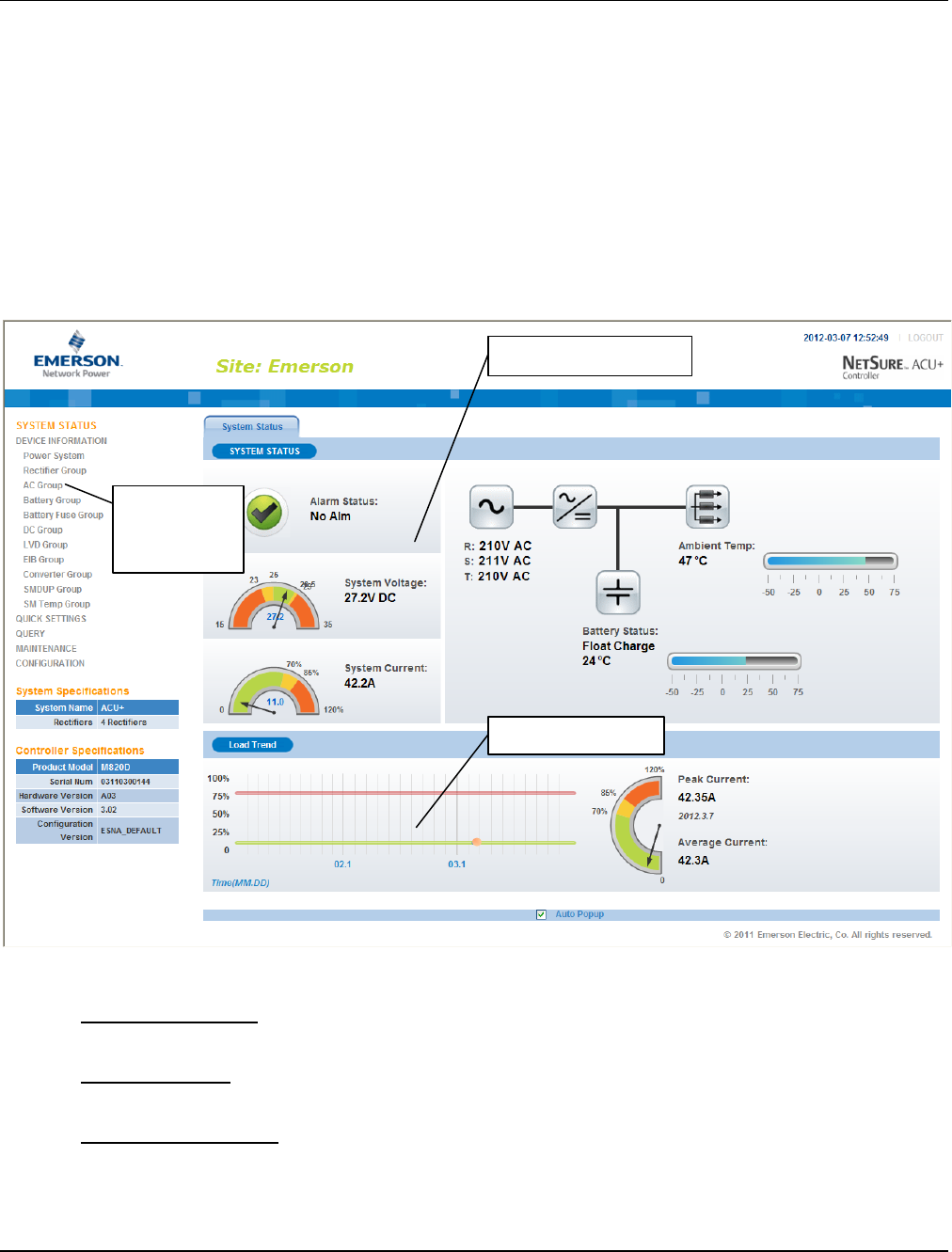
User Instructions UM1M820BNA
Spec No. 1M820BNA (Model M820B) Issue AH, March 4, 2013
Spec No. 1M820DNA (Model M820D)
Chapter 4. WEB Interface Menus 113
This document is property of Emerson Network Power, Energy Systems, North America, Inc. and contains confidential and proprietary information owned by Emerson Network Power, Energy
Systems, North America, Inc. Any copying, use, or disclosure of it without the written permission of Emerson Network Power, Energy Systems, North America, Inc. is strictly prohibited.
CHAPTER 4. WEB INTERFACE MENUS
4.1 Overview
This section provides descriptions of the WEB Interface Menus. Refer also to “2.2 Passwords and Access
Levels” and “2.4 WEB Interface Access”. For parameter descriptions, refer to “3.3 Description of Local
Display (and Web Interface) Menus Line Items”. For Local Display Menus, refer to “Chapter 3. Local
Display Menus”.
4.2 Homepage
In the WEB Interface, after entering a valid User Name and Password and clicking LOGIN, the
"HOMEPAGE" window opens. See also “2.4.6. Logging into the Controller”.
The homepage window is divided into three areas: System Status, Load Trend, and Menu Navigation.
System Status Area
System status is displayed in this area (top right section of Homepage window).
Load Trend Area
A load trend visual is displayed in this area (bottom right section of Homepage window).
Menu Navigation Area
Available menus are displayed in this area (left section of Homepage window).
When you click on a menu name in this area, the menu opens in the right section of the window (replacing
the system status and load trend screens).
System Status Area
Load Trend Area
Menu
Navigation
Area
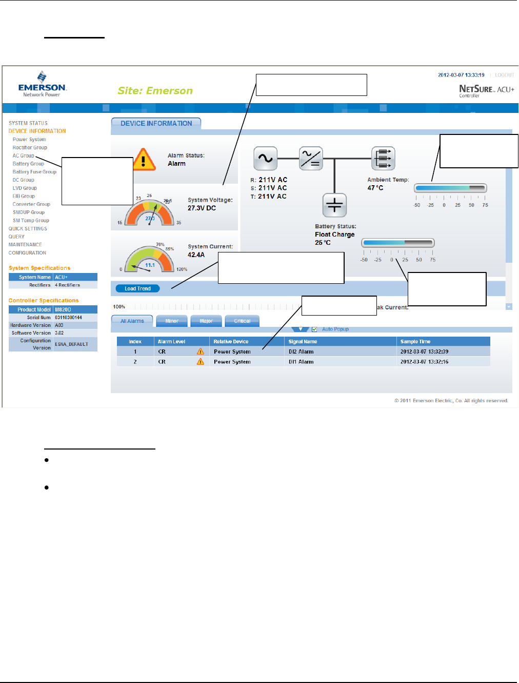
UM1M820BNA User Instructions
Issue AH, March 4, 2013 Spec No. 1M820BNA (Model M820B)
Spec No. 1M820DNA (Model M820D)
114 Chapter 4. WEB Interface Menus
This document is property of Emerson Network Power, Energy Systems, North America, Inc. and contains confidential and proprietary information owned by Emerson Network Power, Energy
Systems, North America, Inc. Any copying, use, or disclosure of it without the written permission of Emerson Network Power, Energy Systems, North America, Inc. is strictly prohibited.
When the system is in an alarm state, a fourth area (Alarms) appears at the bottom of the display.
Alarms Area
Alarms are displayed in this area (bottom right section of Homepage window).
Temperature Readings
The temperature sensor set as the “Amb Temp Sensor” in the Power System menu is the sensor
which displays the ambient temperature on the Web Interface’s Homepage.
The temperature compensation sensor is the sensor which displays the battery temperature on the
Web Interface’s Homepage.
System Status Area
Load Trend Area
(use scroll bar to view)
Menu
Navigation
Area
Alarms Area
Ambient
Temperature
Battery
Temperature

User Instructions UM1M820BNA
Spec No. 1M820BNA (Model M820B) Issue AH, March 4, 2013
Spec No. 1M820DNA (Model M820D)
Chapter 4. WEB Interface Menus 115
This document is property of Emerson Network Power, Energy Systems, North America, Inc. and contains confidential and proprietary information owned by Emerson Network Power, Energy
Systems, North America, Inc. Any copying, use, or disclosure of it without the written permission of Emerson Network Power, Energy Systems, North America, Inc. is strictly prohibited.
4.3 Menu Navigation Window
When a menu is clicked on in the left side of the window (menu navigation area), the menu selected is
displayed in the top right section of the window (the system status and load trend screens are replaced
with a selected menu screen). Note that there is a menu item named SYSTEM STATUS to return to the
system status screen.
Selected Menu Area

UM1M820BNA User Instructions
Issue AH, March 4, 2013 Spec No. 1M820BNA (Model M820B)
Spec No. 1M820DNA (Model M820D)
116 Chapter 4. WEB Interface Menus
This document is property of Emerson Network Power, Energy Systems, North America, Inc. and contains confidential and proprietary information owned by Emerson Network Power, Energy
Systems, North America, Inc. Any copying, use, or disclosure of it without the written permission of Emerson Network Power, Energy Systems, North America, Inc. is strictly prohibited.
4.3.1 Alarms
The bottom right section of the window shows any alarms active in the power system.
When viewing the alarms, click the “arrow” icon to collapse the alarm list. Click the "arrow" icon
again to expand the alarm list. Also located next to the “arrow” icon is a check box named
“Auto Popup”. When this box is checked and the alarm window is collapse, a new alarm will cause the
alarm window to open.
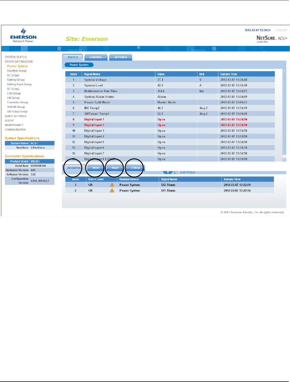
User Instructions UM1M820BNA
Spec No. 1M820BNA (Model M820B) Issue AH, March 4, 2013
Spec No. 1M820DNA (Model M820D)
Chapter 4. WEB Interface Menus 117
This document is property of Emerson Network Power, Energy Systems, North America, Inc. and contains confidential and proprietary information owned by Emerson Network Power, Energy
Systems, North America, Inc. Any copying, use, or disclosure of it without the written permission of Emerson Network Power, Energy Systems, North America, Inc. is strictly prohibited.
The alarms area contains tabs to allow viewing all alarms or a type of alarm (severity). For example, click
the Minor tab to display alarms set as Minor alarms.
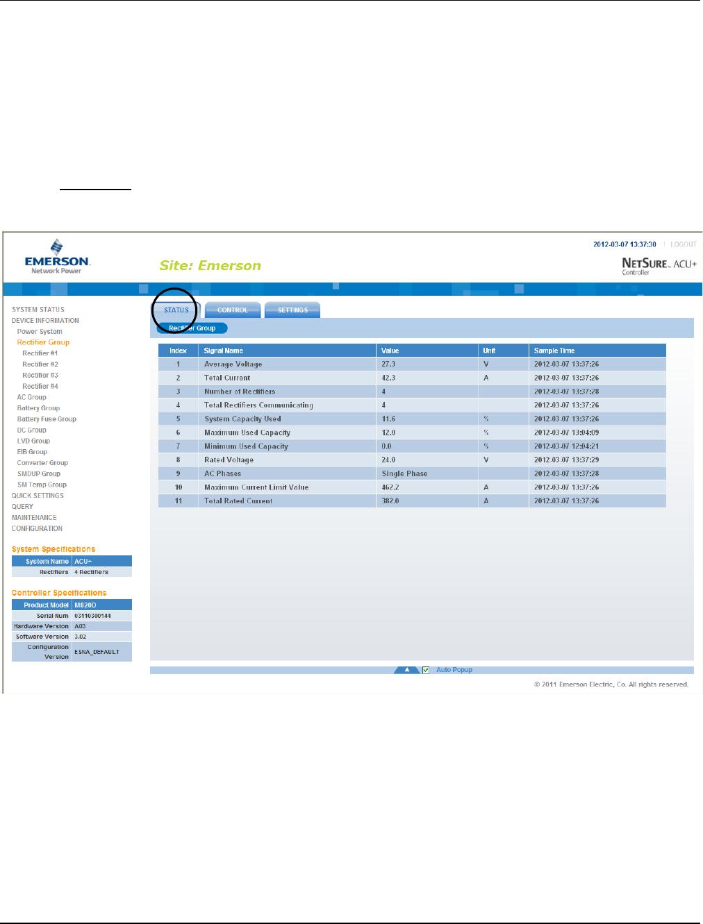
UM1M820BNA User Instructions
Issue AH, March 4, 2013 Spec No. 1M820BNA (Model M820B)
Spec No. 1M820DNA (Model M820D)
118 Chapter 4. WEB Interface Menus
This document is property of Emerson Network Power, Energy Systems, North America, Inc. and contains confidential and proprietary information owned by Emerson Network Power, Energy
Systems, North America, Inc. Any copying, use, or disclosure of it without the written permission of Emerson Network Power, Energy Systems, North America, Inc. is strictly prohibited.
4.4 Device Information Menu
Listed in this menu are the device groups installed in the system. Click on a device group to view its
current or logged operating parameters, set programmable parameters, and change control settings.
The following sections describe the Rectifier and Battery device groups as samples of how to use these
menus.
4.4.1 Rectifier Group
The “Rectifier Group” menu contains three tabs: Status, Control, and Settings.
Status Tab
This tab displays the actually sampled values such as “Number of Rectifiers”, “Total Current”, and so on.
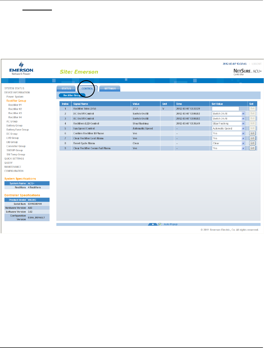
User Instructions UM1M820BNA
Spec No. 1M820BNA (Model M820B) Issue AH, March 4, 2013
Spec No. 1M820DNA (Model M820D)
Chapter 4. WEB Interface Menus 119
This document is property of Emerson Network Power, Energy Systems, North America, Inc. and contains confidential and proprietary information owned by Emerson Network Power, Energy
Systems, North America, Inc. Any copying, use, or disclosure of it without the written permission of Emerson Network Power, Energy Systems, North America, Inc. is strictly prohibited.
Control Tab
This tab displays the rectifier’s control settings and allows you to change these settings. For example, a
User can select a value of “Full Speed” for “Fan Speed Control” then click on “Set” to make the rectifier’s
fan run at full speed. The control command is effective for all the rectifiers.
Note: Settings that appear "grayed out" can only be made when the Controller is in the "manual control"
state. If the Controller is set for "automatic" control, change the “Auto/Man State” setting first to the
“Man” setting.
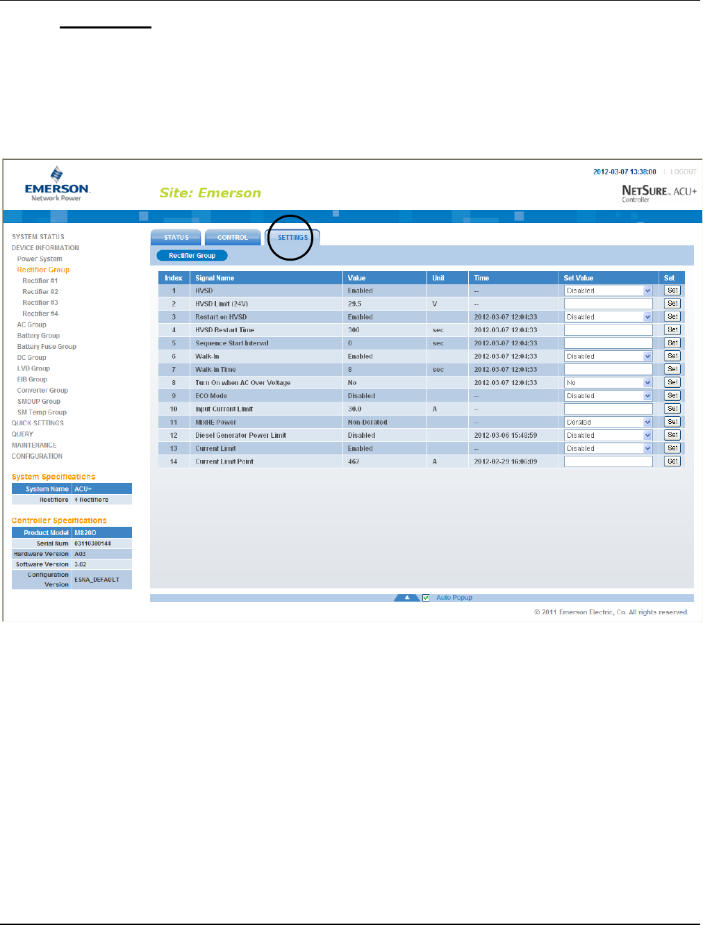
UM1M820BNA User Instructions
Issue AH, March 4, 2013 Spec No. 1M820BNA (Model M820B)
Spec No. 1M820DNA (Model M820D)
120 Chapter 4. WEB Interface Menus
This document is property of Emerson Network Power, Energy Systems, North America, Inc. and contains confidential and proprietary information owned by Emerson Network Power, Energy
Systems, North America, Inc. Any copying, use, or disclosure of it without the written permission of Emerson Network Power, Energy Systems, North America, Inc. is strictly prohibited.
Settings Tab
This tab displays the rectifier’s programmable settings and allows you to change these settings. For
example, a User can select a value of “Disabled” for “Walk-In” then click on “Set” to disable the walk-in
function of all the rectifiers.
Note: Settings that appear "grayed out" can only be made when the Controller is in the "manual control"
state. If the Controller is set for "automatic" control, change the “Auto/Man State” setting first to the
“Man” setting.
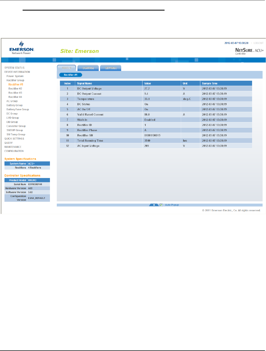
User Instructions UM1M820BNA
Spec No. 1M820BNA (Model M820B) Issue AH, March 4, 2013
Spec No. 1M820DNA (Model M820D)
Chapter 4. WEB Interface Menus 121
This document is property of Emerson Network Power, Energy Systems, North America, Inc. and contains confidential and proprietary information owned by Emerson Network Power, Energy
Systems, North America, Inc. Any copying, use, or disclosure of it without the written permission of Emerson Network Power, Energy Systems, North America, Inc. is strictly prohibited.
Selecting an Individual Rectifier from the Rectifier Group
Expanding the Rectifier Group menu selection in the left pane lists the individual rectifiers installed in the
system in sub-menus. Click on an individual rectifier listed in the sub-menus in the left pane to display its
menu screen in the right pane.
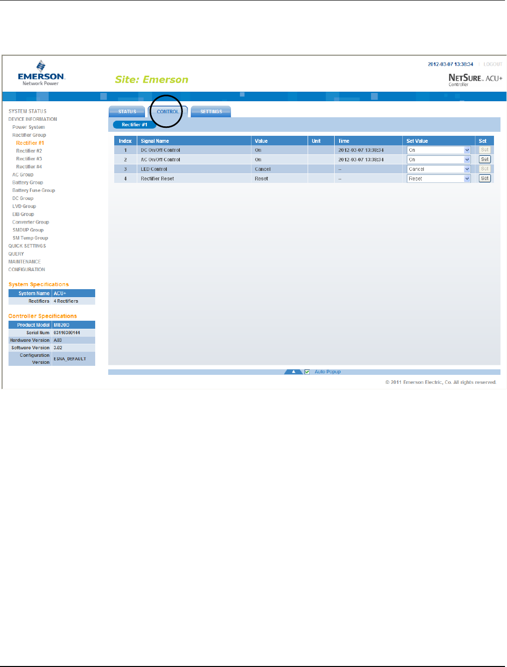
UM1M820BNA User Instructions
Issue AH, March 4, 2013 Spec No. 1M820BNA (Model M820B)
Spec No. 1M820DNA (Model M820D)
122 Chapter 4. WEB Interface Menus
This document is property of Emerson Network Power, Energy Systems, North America, Inc. and contains confidential and proprietary information owned by Emerson Network Power, Energy
Systems, North America, Inc. Any copying, use, or disclosure of it without the written permission of Emerson Network Power, Energy Systems, North America, Inc. is strictly prohibited.
An “Individual Rectifier” menu also contains the three tabs: Status, Control, and Settings. The menu items
in each of these tabs are specific to the rectifier selected. For example, clicking the Control tab displays
the control settings for the selected rectifier.

User Instructions UM1M820BNA
Spec No. 1M820BNA (Model M820B) Issue AH, March 4, 2013
Spec No. 1M820DNA (Model M820D)
Chapter 4. WEB Interface Menus 123
This document is property of Emerson Network Power, Energy Systems, North America, Inc. and contains confidential and proprietary information owned by Emerson Network Power, Energy
Systems, North America, Inc. Any copying, use, or disclosure of it without the written permission of Emerson Network Power, Energy Systems, North America, Inc. is strictly prohibited.
4.4.2 Battery Group (except Li-Ion Battery Configuration)
The “Battery Group” menu contains three tabs: Status, Control, and Settings.
Status Tab
This tab displays the actually sampled values such as “Battery Voltage” and “Total Battery Current”.
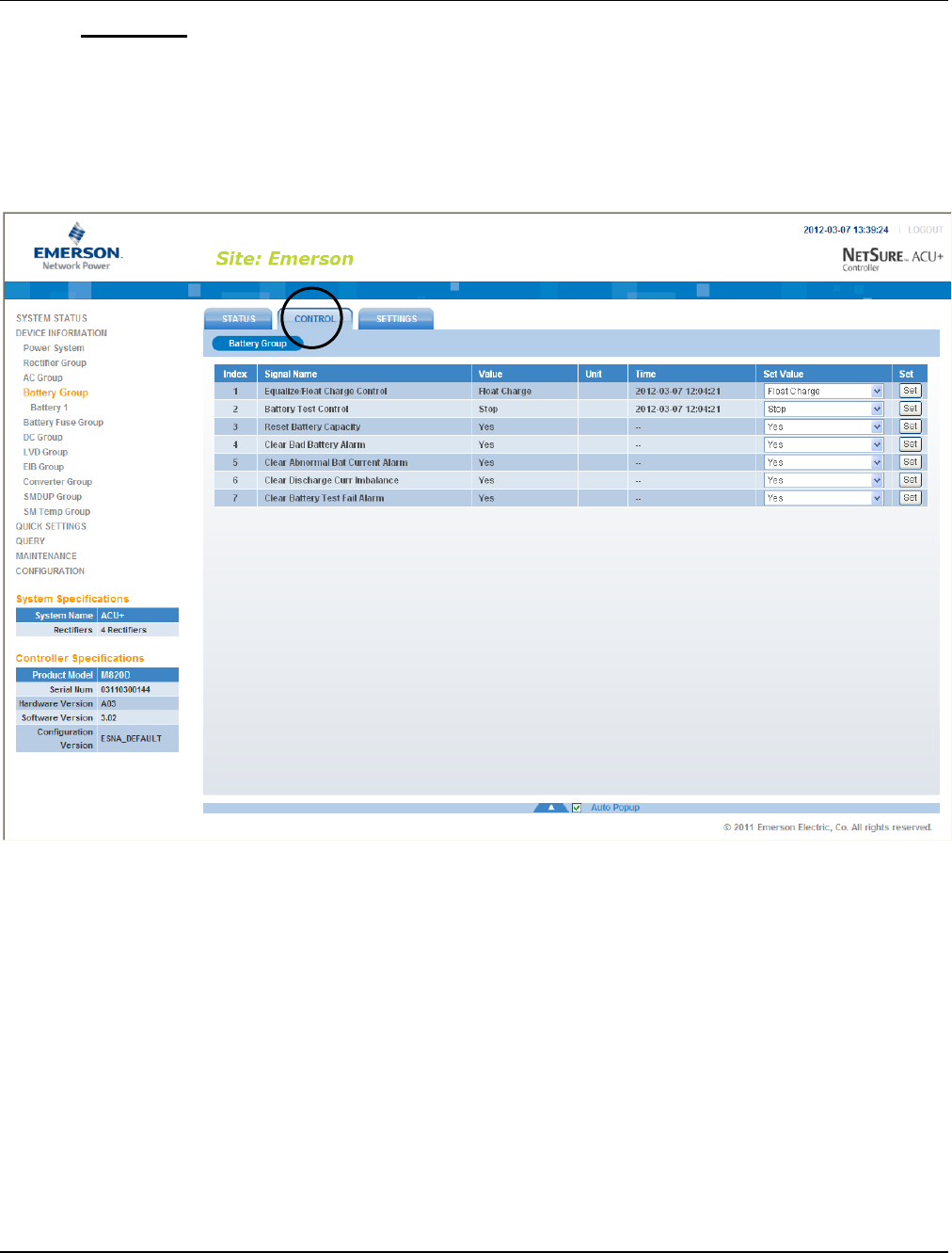
UM1M820BNA User Instructions
Issue AH, March 4, 2013 Spec No. 1M820BNA (Model M820B)
Spec No. 1M820DNA (Model M820D)
124 Chapter 4. WEB Interface Menus
This document is property of Emerson Network Power, Energy Systems, North America, Inc. and contains confidential and proprietary information owned by Emerson Network Power, Energy
Systems, North America, Inc. Any copying, use, or disclosure of it without the written permission of Emerson Network Power, Energy Systems, North America, Inc. is strictly prohibited.
Control Tab
This tab displays the battery’s control settings and allows you to change these settings. For example, a
User can select a value of “Equalize Charge” for “Equalize/Float Charge Control” then click on “Set” to
change the charge mode from float to equalize.
Note: Settings that appear "grayed out" can only be made when the Controller is in the "manual control"
state. If the Controller is set for "automatic" control, change the “Auto/Man State” setting first to the
“Man” setting.
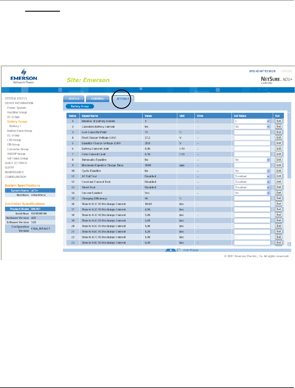
User Instructions UM1M820BNA
Spec No. 1M820BNA (Model M820B) Issue AH, March 4, 2013
Spec No. 1M820DNA (Model M820D)
Chapter 4. WEB Interface Menus 125
This document is property of Emerson Network Power, Energy Systems, North America, Inc. and contains confidential and proprietary information owned by Emerson Network Power, Energy
Systems, North America, Inc. Any copying, use, or disclosure of it without the written permission of Emerson Network Power, Energy Systems, North America, Inc. is strictly prohibited.
Settings Tab
This tab displays the battery’s programmable settings and allows you to change these settings. For
example, a User can select a value of “Yes” for “Automatic Equalize” then click on “Set” to make the
setting become effective.
Note: Settings that appear "grayed out" can only be made when the Controller is in the "manual control"
state. If the Controller is set for "automatic" control, change the “Auto/Man State” setting first to the
“Man” setting.
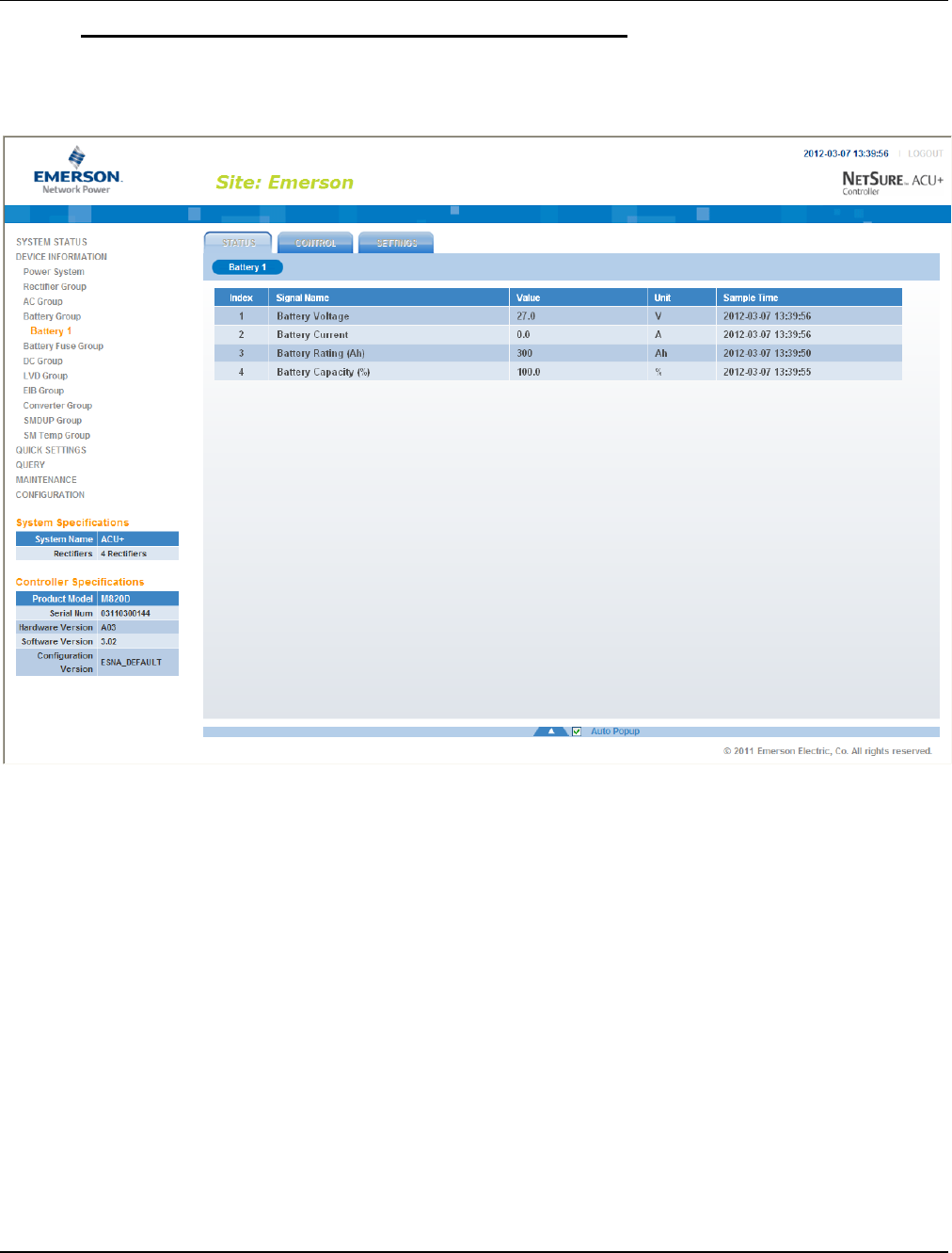
UM1M820BNA User Instructions
Issue AH, March 4, 2013 Spec No. 1M820BNA (Model M820B)
Spec No. 1M820DNA (Model M820D)
126 Chapter 4. WEB Interface Menus
This document is property of Emerson Network Power, Energy Systems, North America, Inc. and contains confidential and proprietary information owned by Emerson Network Power, Energy
Systems, North America, Inc. Any copying, use, or disclosure of it without the written permission of Emerson Network Power, Energy Systems, North America, Inc. is strictly prohibited.
Selecting an Individual Battery String from the Battery Group
Expanding the Battery Group menu selection in the left pane lists the individual battery strings installed in
the system in sub-menus. Click on an individual battery string listed in the sub-menus in the left pane to
display its menu screen in the right pane.
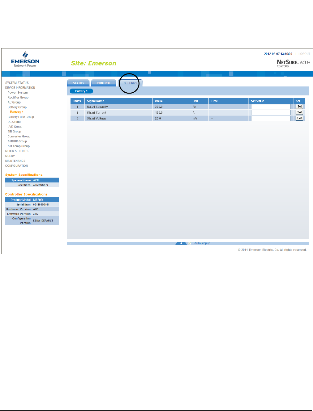
User Instructions UM1M820BNA
Spec No. 1M820BNA (Model M820B) Issue AH, March 4, 2013
Spec No. 1M820DNA (Model M820D)
Chapter 4. WEB Interface Menus 127
This document is property of Emerson Network Power, Energy Systems, North America, Inc. and contains confidential and proprietary information owned by Emerson Network Power, Energy
Systems, North America, Inc. Any copying, use, or disclosure of it without the written permission of Emerson Network Power, Energy Systems, North America, Inc. is strictly prohibited.
An “Individual Battery String” menu also contains the three tabs: Status, Control, and Settings. The menu
items in each of these tabs are specific to the battery string selected. For example, clicking the Settings
Tab displays the programmable settings for the selected battery string. Note that if you click the Control
tab, nothing will be displayed because the Controller is not allowed to control a single battery string or set
the values of a single battery string.

UM1M820BNA User Instructions
Issue AH, March 4, 2013 Spec No. 1M820BNA (Model M820B)
Spec No. 1M820DNA (Model M820D)
128 Chapter 4. WEB Interface Menus
This document is property of Emerson Network Power, Energy Systems, North America, Inc. and contains confidential and proprietary information owned by Emerson Network Power, Energy
Systems, North America, Inc. Any copying, use, or disclosure of it without the written permission of Emerson Network Power, Energy Systems, North America, Inc. is strictly prohibited.
4.4.3 Battery Group (Li-Ion Battery Configuration)
Status Tab
Control Tab
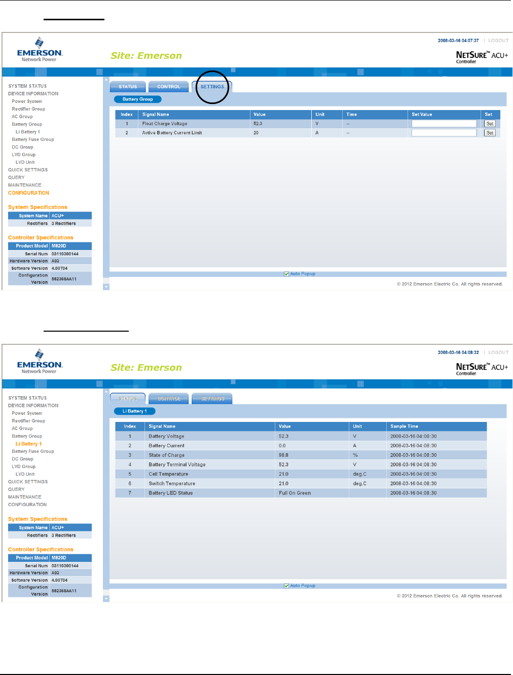
User Instructions UM1M820BNA
Spec No. 1M820BNA (Model M820B) Issue AH, March 4, 2013
Spec No. 1M820DNA (Model M820D)
Chapter 4. WEB Interface Menus 129
This document is property of Emerson Network Power, Energy Systems, North America, Inc. and contains confidential and proprietary information owned by Emerson Network Power, Energy
Systems, North America, Inc. Any copying, use, or disclosure of it without the written permission of Emerson Network Power, Energy Systems, North America, Inc. is strictly prohibited.
Settings Tab
Individual Battery
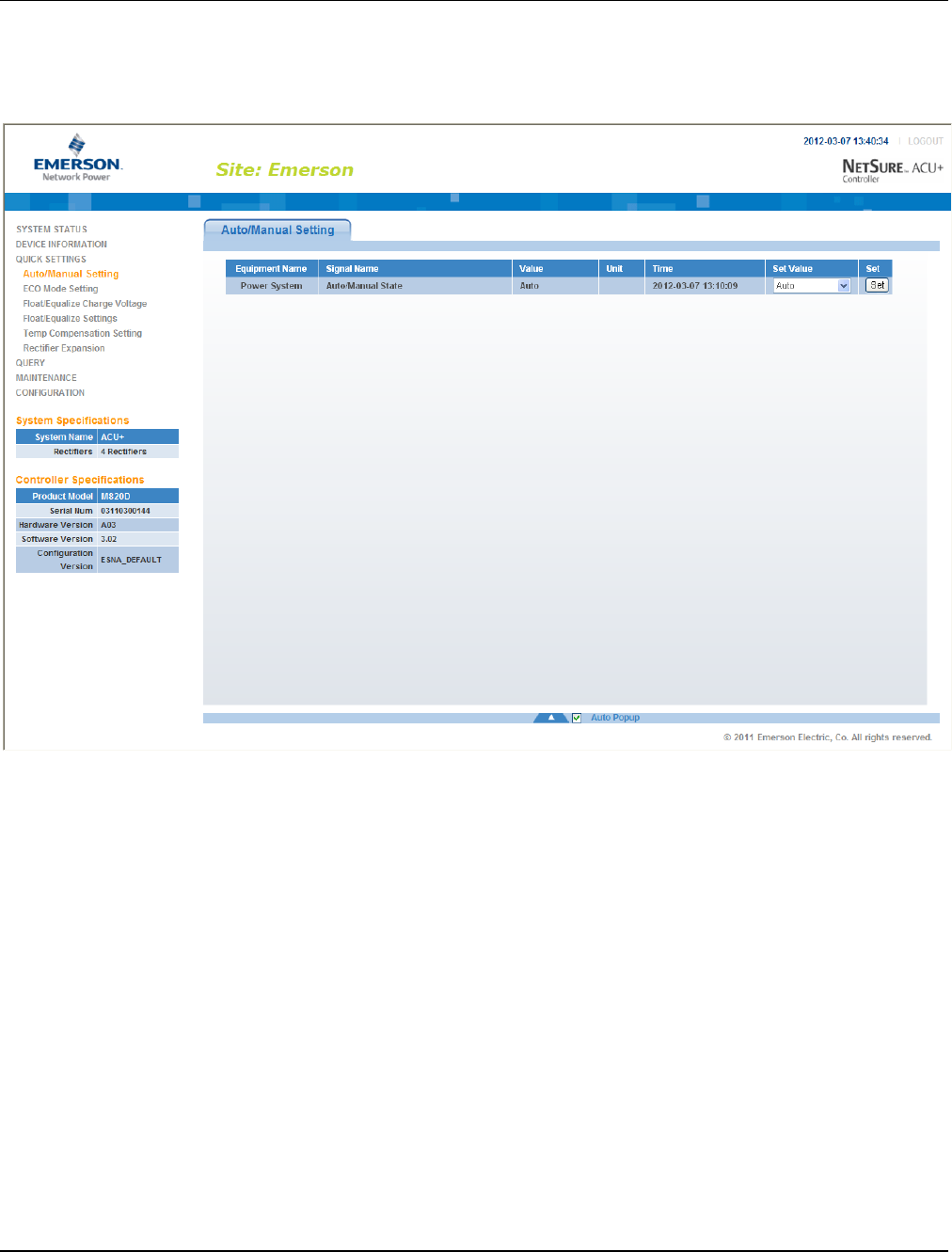
UM1M820BNA User Instructions
Issue AH, March 4, 2013 Spec No. 1M820BNA (Model M820B)
Spec No. 1M820DNA (Model M820D)
130 Chapter 4. WEB Interface Menus
This document is property of Emerson Network Power, Energy Systems, North America, Inc. and contains confidential and proprietary information owned by Emerson Network Power, Energy
Systems, North America, Inc. Any copying, use, or disclosure of it without the written permission of Emerson Network Power, Energy Systems, North America, Inc. is strictly prohibited.
4.5 Quick Settings Menu
The various settings presented in the other menus are grouped here by function as a convenient way to
program these features.
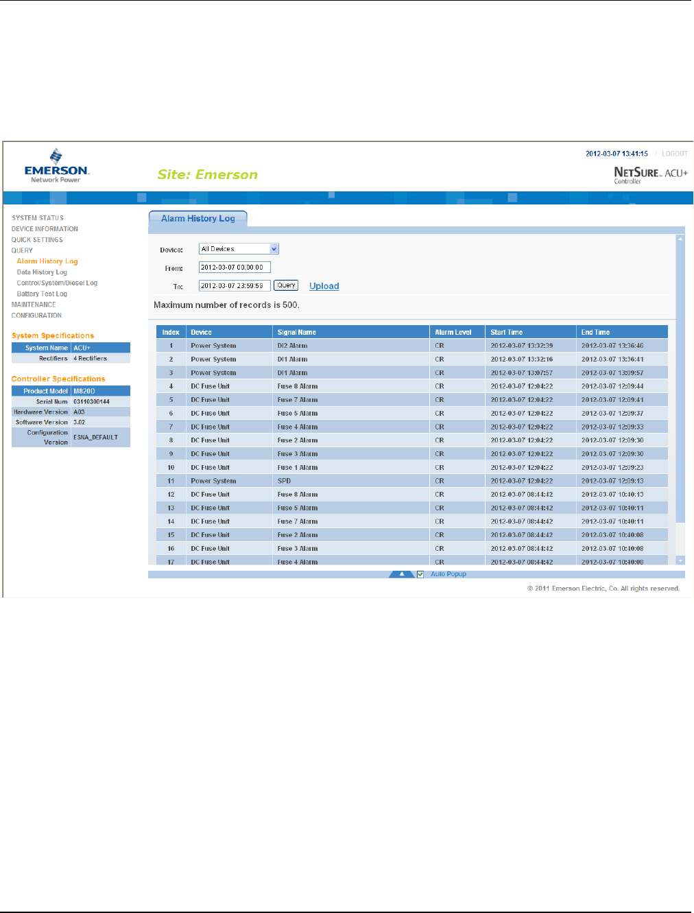
User Instructions UM1M820BNA
Spec No. 1M820BNA (Model M820B) Issue AH, March 4, 2013
Spec No. 1M820DNA (Model M820D)
Chapter 4. WEB Interface Menus 131
This document is property of Emerson Network Power, Energy Systems, North America, Inc. and contains confidential and proprietary information owned by Emerson Network Power, Energy
Systems, North America, Inc. Any copying, use, or disclosure of it without the written permission of Emerson Network Power, Energy Systems, North America, Inc. is strictly prohibited.
4.6 Query Menu
4.6.1 Alarm History Log Sub-Menu
Select the "Device" to query from the drop-down list box. Enter the "from" and "to" time. Click “Query” to
query for alarms within this time slot.
To save the log to your hard drive (in text [.txt] format), click “Upload” and select the path.
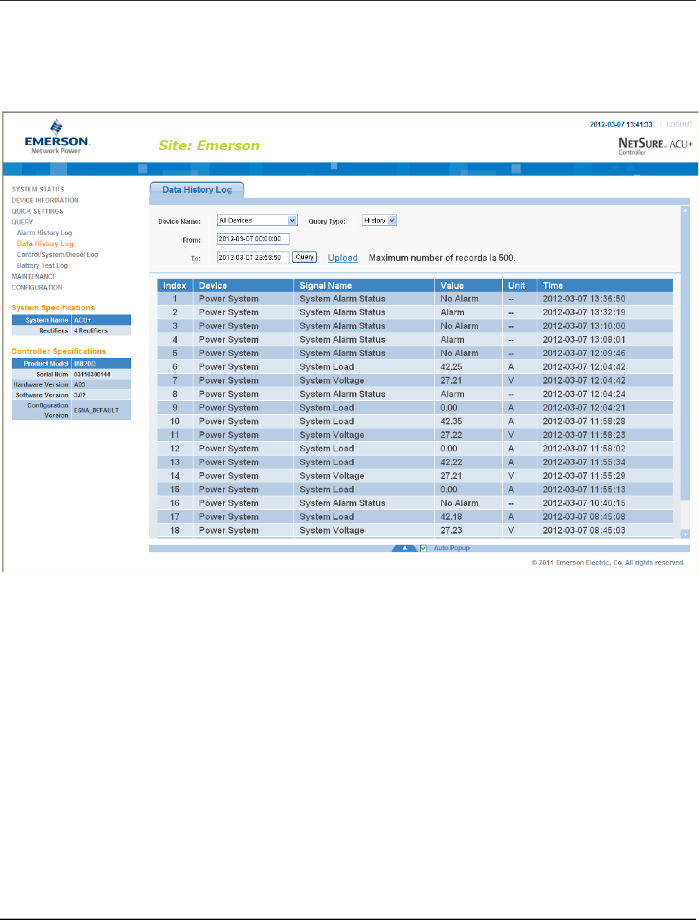
UM1M820BNA User Instructions
Issue AH, March 4, 2013 Spec No. 1M820BNA (Model M820B)
Spec No. 1M820DNA (Model M820D)
132 Chapter 4. WEB Interface Menus
This document is property of Emerson Network Power, Energy Systems, North America, Inc. and contains confidential and proprietary information owned by Emerson Network Power, Energy
Systems, North America, Inc. Any copying, use, or disclosure of it without the written permission of Emerson Network Power, Energy Systems, North America, Inc. is strictly prohibited.
4.6.2 Data History Log Sub-Menu
Select the "Device" to query from the drop-down list box. Enter the "from" and "to" time. Click “Query” to
query for data within this time slot.
To save the log to your hard drive (in text [.txt] format), click “Upload” and select the path.

User Instructions UM1M820BNA
Spec No. 1M820BNA (Model M820B) Issue AH, March 4, 2013
Spec No. 1M820DNA (Model M820D)
Chapter 4. WEB Interface Menus 133
This document is property of Emerson Network Power, Energy Systems, North America, Inc. and contains confidential and proprietary information owned by Emerson Network Power, Energy
Systems, North America, Inc. Any copying, use, or disclosure of it without the written permission of Emerson Network Power, Energy Systems, North America, Inc. is strictly prohibited.
4.6.3 Control/System/Diesel Log Sub-Menu
Select the type of log to query from the drop-down list box. Enter the "from" and "to" time. Click “Query” to
query for data within this time slot.
To save the log to your hard drive (in text [.txt] format), click “Upload” and select the path.
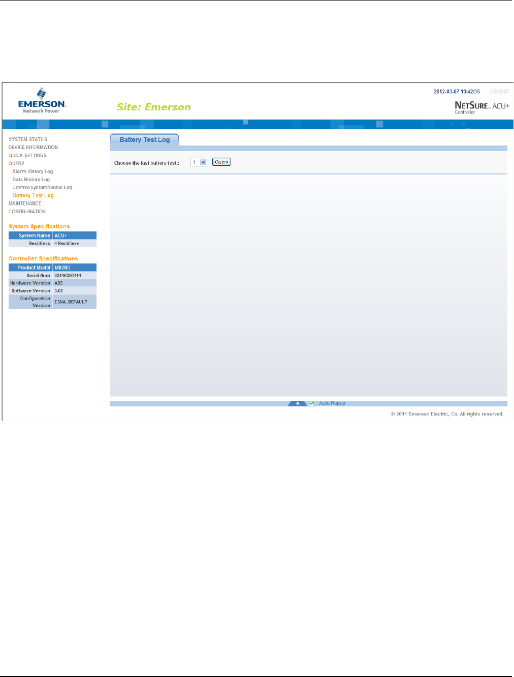
UM1M820BNA User Instructions
Issue AH, March 4, 2013 Spec No. 1M820BNA (Model M820B)
Spec No. 1M820DNA (Model M820D)
134 Chapter 4. WEB Interface Menus
This document is property of Emerson Network Power, Energy Systems, North America, Inc. and contains confidential and proprietary information owned by Emerson Network Power, Energy
Systems, North America, Inc. Any copying, use, or disclosure of it without the written permission of Emerson Network Power, Energy Systems, North America, Inc. is strictly prohibited.
4.6.4 Battery Test Log Sub-Menu
Select the battery test to query from the drop-down list box. Battery test #1 is the most recent. Click “Query”
to query for the battery test results.
To save the log to your hard drive (in text [.txt] format), click “Upload” and select the path.
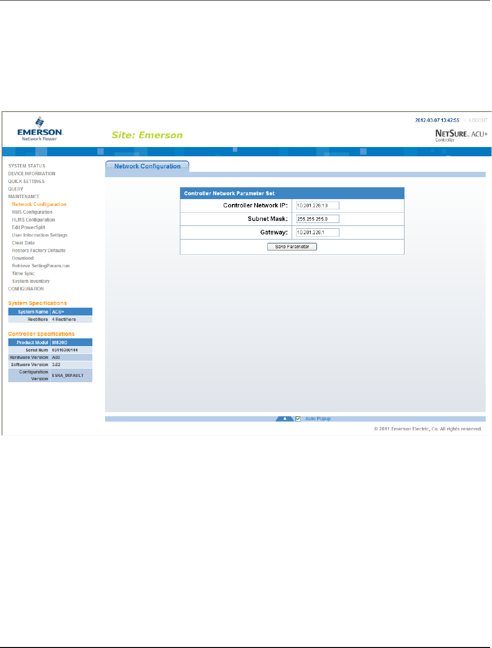
User Instructions UM1M820BNA
Spec No. 1M820BNA (Model M820B) Issue AH, March 4, 2013
Spec No. 1M820DNA (Model M820D)
Chapter 4. WEB Interface Menus 135
This document is property of Emerson Network Power, Energy Systems, North America, Inc. and contains confidential and proprietary information owned by Emerson Network Power, Energy
Systems, North America, Inc. Any copying, use, or disclosure of it without the written permission of Emerson Network Power, Energy Systems, North America, Inc. is strictly prohibited.
4.7 Maintenance Menu
4.7.1 Network Configuration Sub-Menu
You can configure the Controller’s network parameters; such as the IP address, subnet mask, and
gateway. After modifying the network parameters, click “Save Parameter” to validate the change made to
the parameters.
Note: After changing the IP Address, you will need to login again with the new IP address.

UM1M820BNA User Instructions
Issue AH, March 4, 2013 Spec No. 1M820BNA (Model M820B)
Spec No. 1M820DNA (Model M820D)
136 Chapter 4. WEB Interface Menus
This document is property of Emerson Network Power, Energy Systems, North America, Inc. and contains confidential and proprietary information owned by Emerson Network Power, Energy
Systems, North America, Inc. Any copying, use, or disclosure of it without the written permission of Emerson Network Power, Energy Systems, North America, Inc. is strictly prohibited.
4.7.2 NMS (Network Management System) Configuration Sub-Menu
You can configure the NMS IP, authority, and trap level. You can also add new NMS, modify NMS
information, and delete the selected NMS through the interface. You can also set the trap level.
Note: Only listed IP Addresses will have SNMP access.
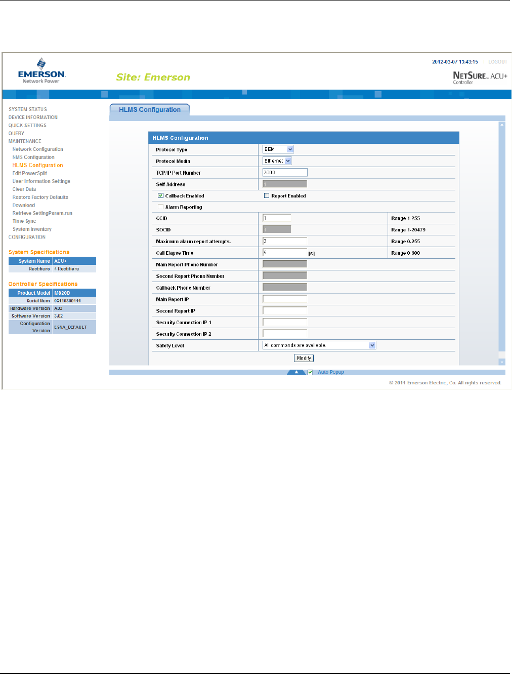
User Instructions UM1M820BNA
Spec No. 1M820BNA (Model M820B) Issue AH, March 4, 2013
Spec No. 1M820DNA (Model M820D)
Chapter 4. WEB Interface Menus 137
This document is property of Emerson Network Power, Energy Systems, North America, Inc. and contains confidential and proprietary information owned by Emerson Network Power, Energy
Systems, North America, Inc. Any copying, use, or disclosure of it without the written permission of Emerson Network Power, Energy Systems, North America, Inc. is strictly prohibited.
4.7.3 HLMS (High Level Management System) Configuration Sub-Menu
For use with HLMS supporting the YDN23 protocol.
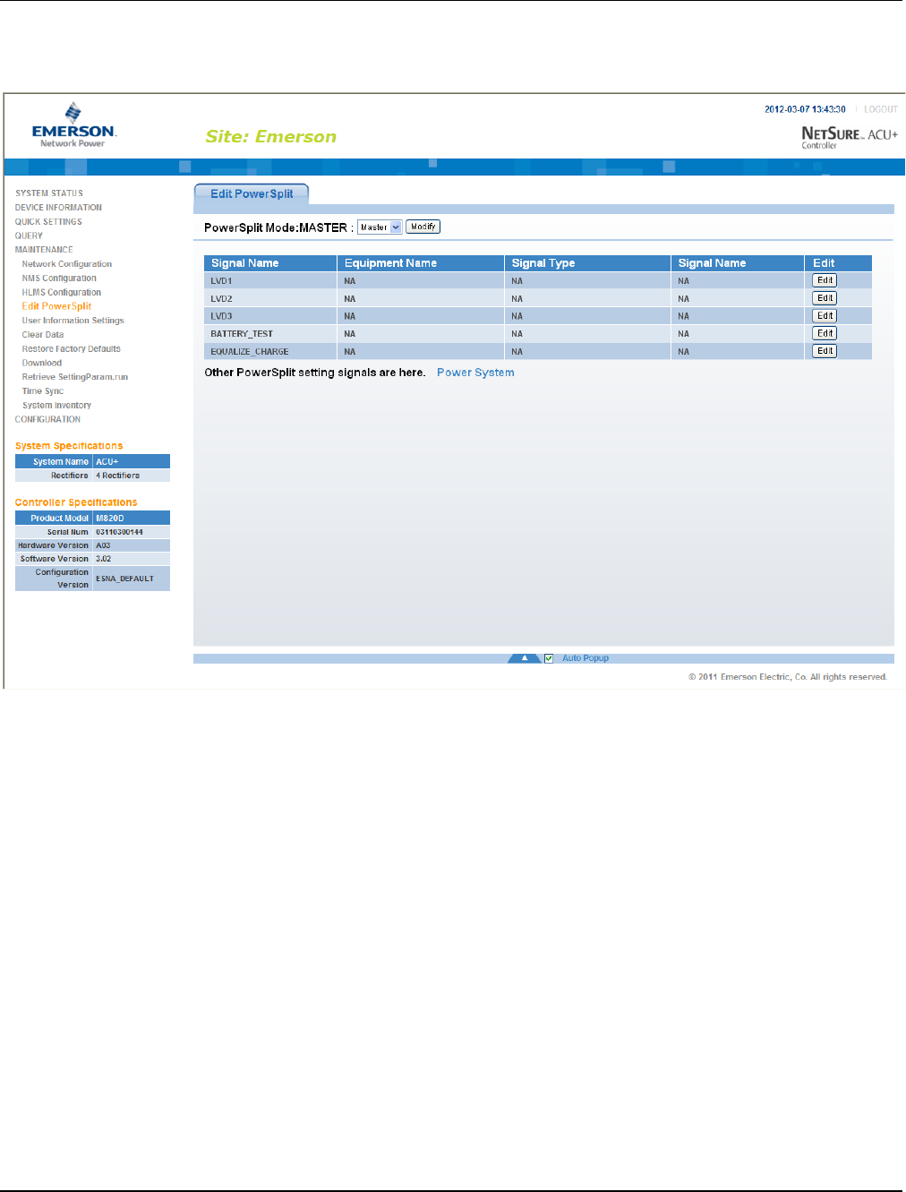
UM1M820BNA User Instructions
Issue AH, March 4, 2013 Spec No. 1M820BNA (Model M820B)
Spec No. 1M820DNA (Model M820D)
138 Chapter 4. WEB Interface Menus
This document is property of Emerson Network Power, Energy Systems, North America, Inc. and contains confidential and proprietary information owned by Emerson Network Power, Energy
Systems, North America, Inc. Any copying, use, or disclosure of it without the written permission of Emerson Network Power, Energy Systems, North America, Inc. is strictly prohibited.
4.7.4 Edit PowerSplit Sub-Menu
You can configure the PowerSplit parameters and associated digital input signals.
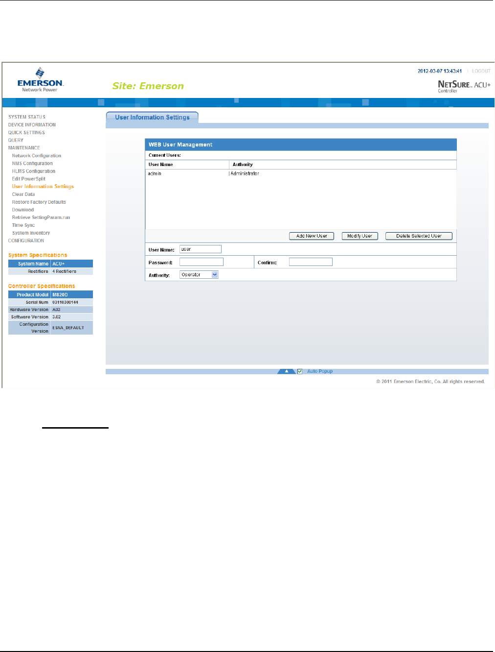
User Instructions UM1M820BNA
Spec No. 1M820BNA (Model M820B) Issue AH, March 4, 2013
Spec No. 1M820DNA (Model M820D)
Chapter 4. WEB Interface Menus 139
This document is property of Emerson Network Power, Energy Systems, North America, Inc. and contains confidential and proprietary information owned by Emerson Network Power, Energy
Systems, North America, Inc. Any copying, use, or disclosure of it without the written permission of Emerson Network Power, Energy Systems, North America, Inc. is strictly prohibited.
4.7.5 User Information Settings Sub-Menu
You can add, edit, and delete Users. These are the Users that can log onto the Controller both locally
(local display access) or remotely using the Web Interface.
Adding a User
1) Enter the User’s Name in the “User Name” field (13 characters maximum; the valid characters are
0-9, a-z, A-Z, and _ ).
2) Select the authority of the User from those listed in the "Authority" drop-down list box. See "User
Authority Level" below for a description.
3) Enter a password for this User in the "Password" field (13 characters maximum; the valid
characters are 0-9, a-z, A-Z, and _ ).
4) Re-enter the password for this User in the "Confirm" field.
5) Click the “Add New User” button to add the User.

UM1M820BNA User Instructions
Issue AH, March 4, 2013 Spec No. 1M820BNA (Model M820B)
Spec No. 1M820DNA (Model M820D)
140 Chapter 4. WEB Interface Menus
This document is property of Emerson Network Power, Energy Systems, North America, Inc. and contains confidential and proprietary information owned by Emerson Network Power, Energy
Systems, North America, Inc. Any copying, use, or disclosure of it without the written permission of Emerson Network Power, Energy Systems, North America, Inc. is strictly prohibited.
Modifying an Existing User
1) Select the User to be modified from those listed in the "Current Users" list.
2) Modify the parameters of this User in the "User Name", "Authority", and/or "Password" field.
3) Click the “Modify User” button to modify the parameters of this User.
Deleting a User
1) Select the User to be deleted from those listed in the "Current Users" list.
2) Click the “Delete Selected User” button to delete this User.
User Authority Level
A User is assigned one of the following "Authority Levels".
Each Authority Level gives a User access to specific menus. A User has access to his/her level menus,
plus all menus of the lesser authority levels.
Authority Level
User Authority
Browser
The User can only read (browse) information in the menus.
Operator
The User has access to the system "Control" menus.
Engineer
The User has access to the system "Setting" menus and can download
the configuration file.
Administrator
The User has full access to all menus; including update the OS
application and modifying, adding, and deleting Users.

User Instructions UM1M820BNA
Spec No. 1M820BNA (Model M820B) Issue AH, March 4, 2013
Spec No. 1M820DNA (Model M820D)
Chapter 4. WEB Interface Menus 141
This document is property of Emerson Network Power, Energy Systems, North America, Inc. and contains confidential and proprietary information owned by Emerson Network Power, Energy
Systems, North America, Inc. Any copying, use, or disclosure of it without the written permission of Emerson Network Power, Energy Systems, North America, Inc. is strictly prohibited.
4.7.6 Clear Data Sub-Menu
Select the data log to be cleared from those listed in the drop-down list box. Click on the “Clear” button to
clear the corresponding data.

UM1M820BNA User Instructions
Issue AH, March 4, 2013 Spec No. 1M820BNA (Model M820B)
Spec No. 1M820DNA (Model M820D)
142 Chapter 4. WEB Interface Menus
This document is property of Emerson Network Power, Energy Systems, North America, Inc. and contains confidential and proprietary information owned by Emerson Network Power, Energy
Systems, North America, Inc. Any copying, use, or disclosure of it without the written permission of Emerson Network Power, Energy Systems, North America, Inc. is strictly prohibited.
4.7.7 Restore Factory Defaults Sub-Menu
To return all configuration values to their factory default values, click on the “Restore Defaults” button.
Click “OK” to confirm to overwrite the existing configuration files with the factory default configuration files.
For the default settings to become effective, the Controller must be rebooted. Click on the “Reboot
Controller” button to reboot the Controller.
Warning: When you restore defaults, the Controller’s existing configuration and parameter
settings will be lost.
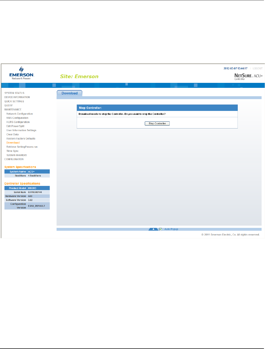
User Instructions UM1M820BNA
Spec No. 1M820BNA (Model M820B) Issue AH, March 4, 2013
Spec No. 1M820DNA (Model M820D)
Chapter 4. WEB Interface Menus 143
This document is property of Emerson Network Power, Energy Systems, North America, Inc. and contains confidential and proprietary information owned by Emerson Network Power, Energy
Systems, North America, Inc. Any copying, use, or disclosure of it without the written permission of Emerson Network Power, Energy Systems, North America, Inc. is strictly prohibited.
4.7.8 Download Sub-Menu
You can download (from your hard drive into the Controller) a configuration package, application ("All")
package, or language package (filename of each has a tar or tar.gz extension). You can also download
the file "SettingParam.run (see “4.7.9 Retrieve ‘SettingParam.run’ File Sub-Menu” for a description)”.
You can upload (from the Controller to your hard drive) a configuration package or language package.
To download a file, you need to shut down the Controller first. When you select the "Download" submenu,
the "Stop Controller" window opens. Click on the “Stop Controller” button.
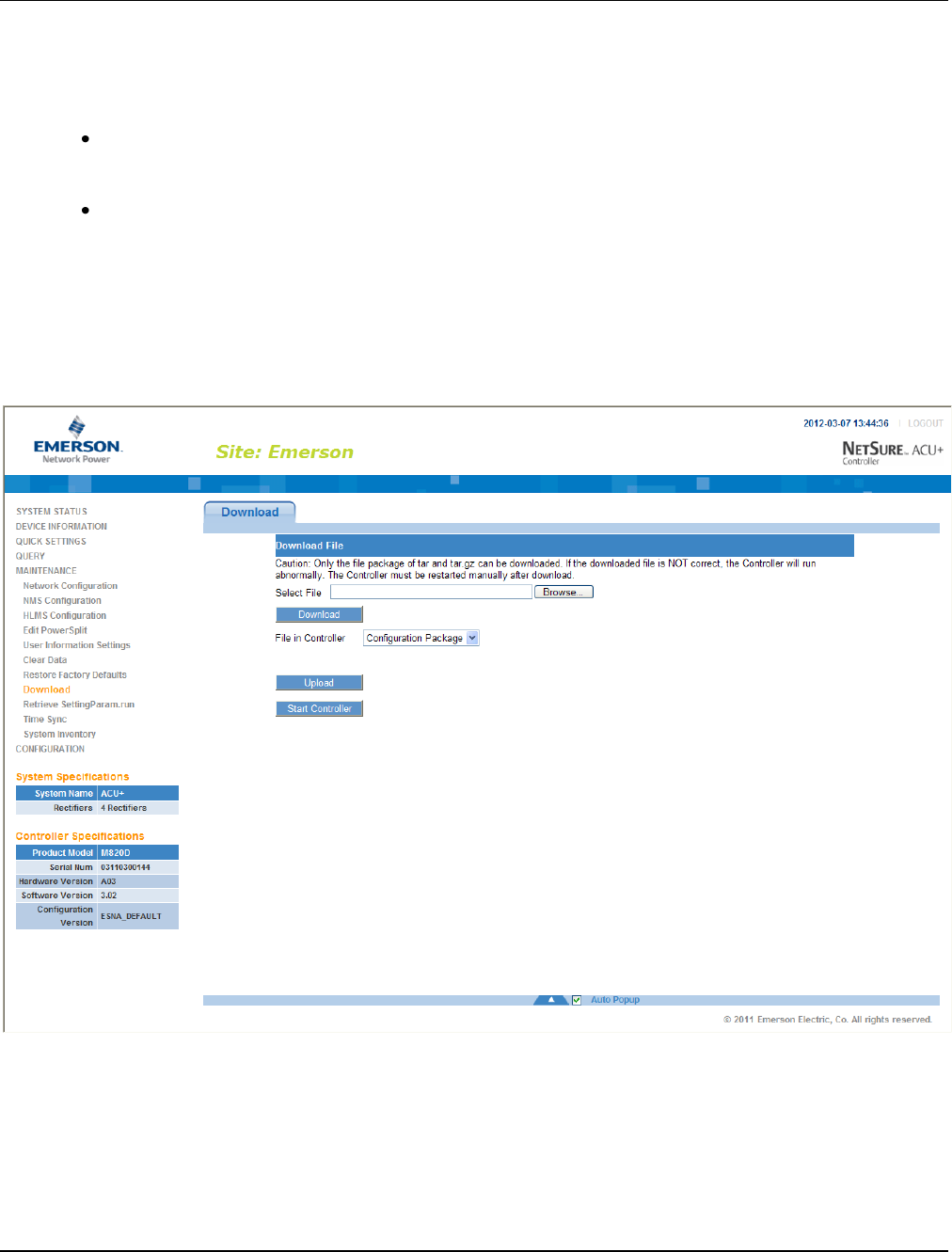
UM1M820BNA User Instructions
Issue AH, March 4, 2013 Spec No. 1M820BNA (Model M820B)
Spec No. 1M820DNA (Model M820D)
144 Chapter 4. WEB Interface Menus
This document is property of Emerson Network Power, Energy Systems, North America, Inc. and contains confidential and proprietary information owned by Emerson Network Power, Energy
Systems, North America, Inc. Any copying, use, or disclosure of it without the written permission of Emerson Network Power, Energy Systems, North America, Inc. is strictly prohibited.
The following window opens.
Warning: Never navigate from this web page without first clicking on "Start Controller". If you do,
you will not have web access. A manual system reset is required to restore web
access.
To download a package or a "SettingParam.run” file, click the “Browse….” button and navigate to the
folder where the file to download is located. Select the file to be downloaded and then click the
“Download” button. Click “Start Controller” to restart the Controller with the downloaded file installed.
To upload a file, select "Configuration Package” or “Language Package” from the "File in Controller"
drop-down list box, and click on the “Upload” button to save the file to your computer.
Note: Configuration Package is a package of files containing all the default parameter settings and the
current settings for relay severity and relay assignments.
Note: Language Package is a package of files containing all the default names of the parameters.
Note: See “4.7.9 Retrieve ‘SettingParam.run’ File Sub-Menu” for a description of the "SettingParam.run”
file.
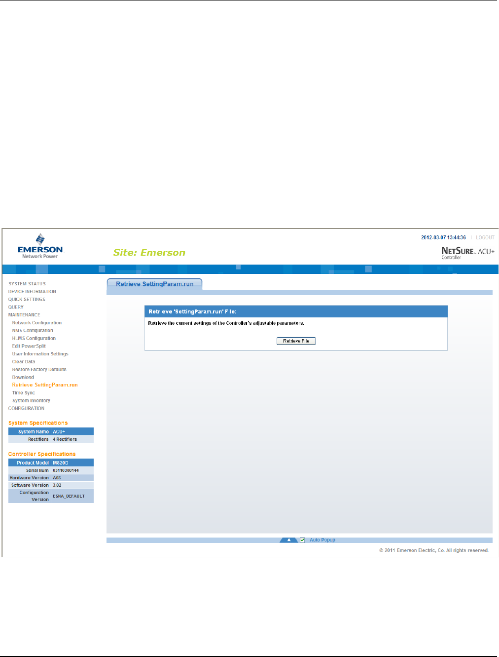
User Instructions UM1M820BNA
Spec No. 1M820BNA (Model M820B) Issue AH, March 4, 2013
Spec No. 1M820DNA (Model M820D)
Chapter 4. WEB Interface Menus 145
This document is property of Emerson Network Power, Energy Systems, North America, Inc. and contains confidential and proprietary information owned by Emerson Network Power, Energy
Systems, North America, Inc. Any copying, use, or disclosure of it without the written permission of Emerson Network Power, Energy Systems, North America, Inc. is strictly prohibited.
4.7.9 Retrieve ‘SettingParam.run’ File Sub-Menu
A file, named “SettingParam.run”, is automatically created by the Controller whenever a User makes
changes to any parameter settings via the LCD or WEB interface.
You can upload a “SettingParam.run” file into your computer and then download the file to another
Controller (refer to “4.7.8 Download Sub-Menu”), so that other Controllers can have the same parameters.
Click on the “Retrieve File” button to save the file named "SettingParam.run" to you hard drive.
Note: It is strongly recommended that you save a copy of the “SettingParam.run” file whenever you
customize any parameter settings. Then, if you ever replace the Controller or perform a "Reload
Config" procedure, you can restore your customized settings by downloading the previously saved
“SettingParam.run” file back into the Controller.
Note: Ensure Internet Explorer security settings are set to enable a file to be downloaded.
To aid in file management, you may change the name of the “SettingParam.run” file. The new name can
use alpha and numeric characters preceding the original “SettingParam.run” name (the end of the new file
name must always be “SettingParam.run”; for example, an acceptable filename would be
“seville4SettingParam.run”).
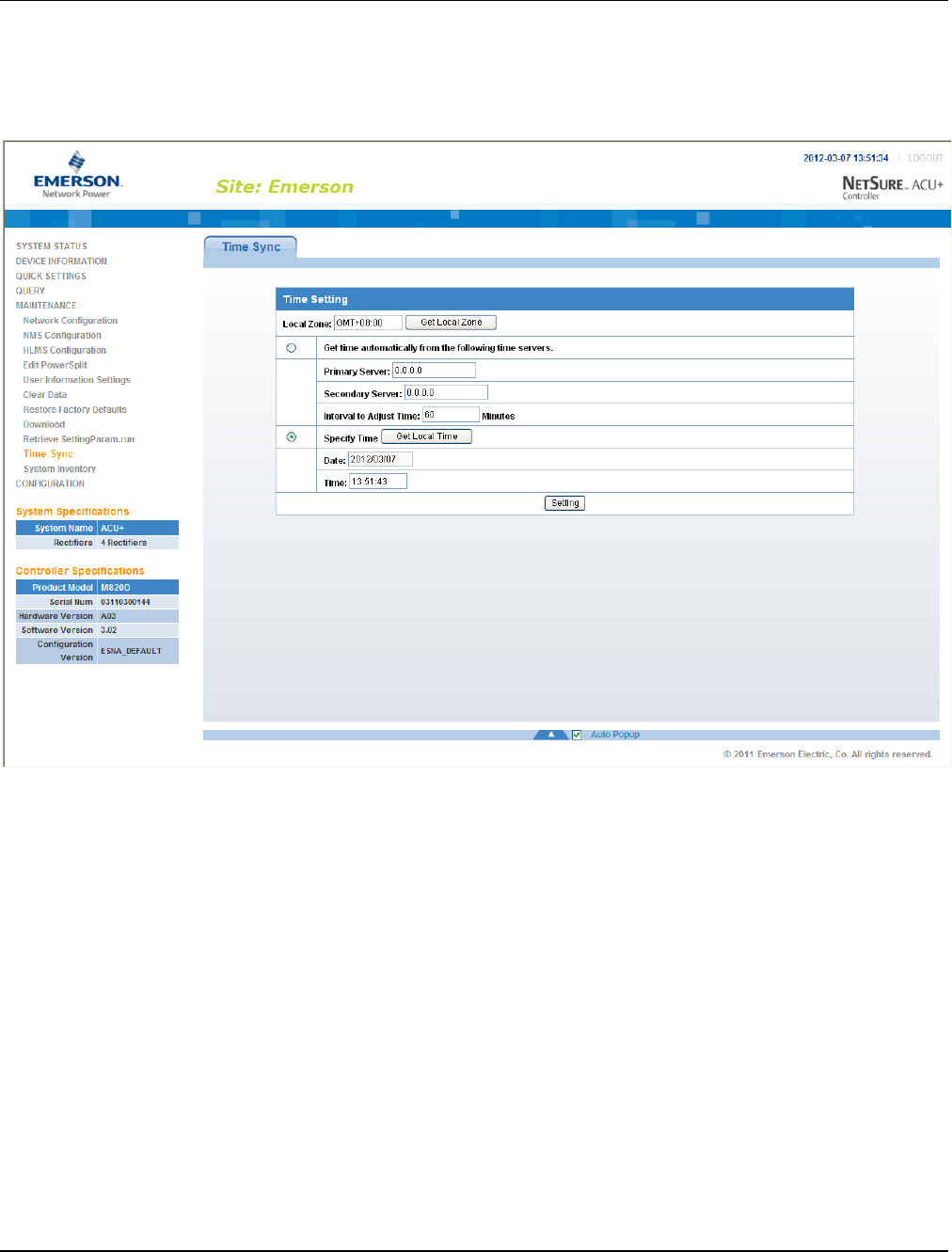
UM1M820BNA User Instructions
Issue AH, March 4, 2013 Spec No. 1M820BNA (Model M820B)
Spec No. 1M820DNA (Model M820D)
146 Chapter 4. WEB Interface Menus
This document is property of Emerson Network Power, Energy Systems, North America, Inc. and contains confidential and proprietary information owned by Emerson Network Power, Energy
Systems, North America, Inc. Any copying, use, or disclosure of it without the written permission of Emerson Network Power, Energy Systems, North America, Inc. is strictly prohibited.
4.7.10 Time Sync Sub-Menu
Use the "Time Sync" submenu to set the Controller’s clock. Click "Get Local Zone" to obtain the time zone
from the local host. Click "Get Local Time" to obtain the time from the local host. Click the "Setting" button
to update the Controller’s time.
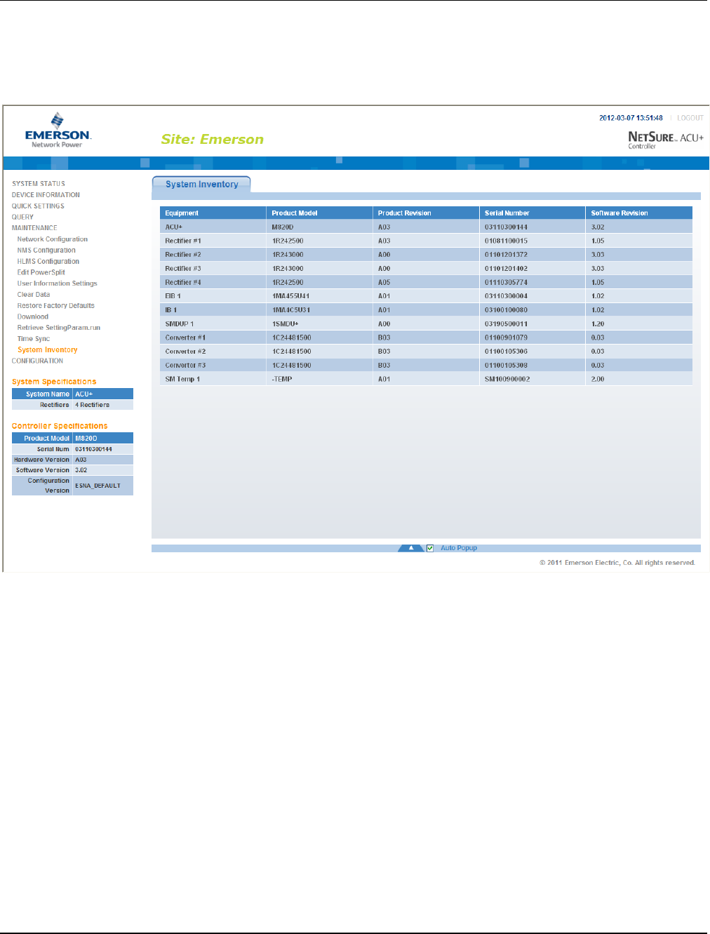
User Instructions UM1M820BNA
Spec No. 1M820BNA (Model M820B) Issue AH, March 4, 2013
Spec No. 1M820DNA (Model M820D)
Chapter 4. WEB Interface Menus 147
This document is property of Emerson Network Power, Energy Systems, North America, Inc. and contains confidential and proprietary information owned by Emerson Network Power, Energy
Systems, North America, Inc. Any copying, use, or disclosure of it without the written permission of Emerson Network Power, Energy Systems, North America, Inc. is strictly prohibited.
4.7.11 System Inventory Sub-Menu
The “System Inventory” submenu allows you to view the product revision, serial number, and software
revision information of the intelligent devices (such as rectifier, SMDU, and IB board) connected to the
Controller.
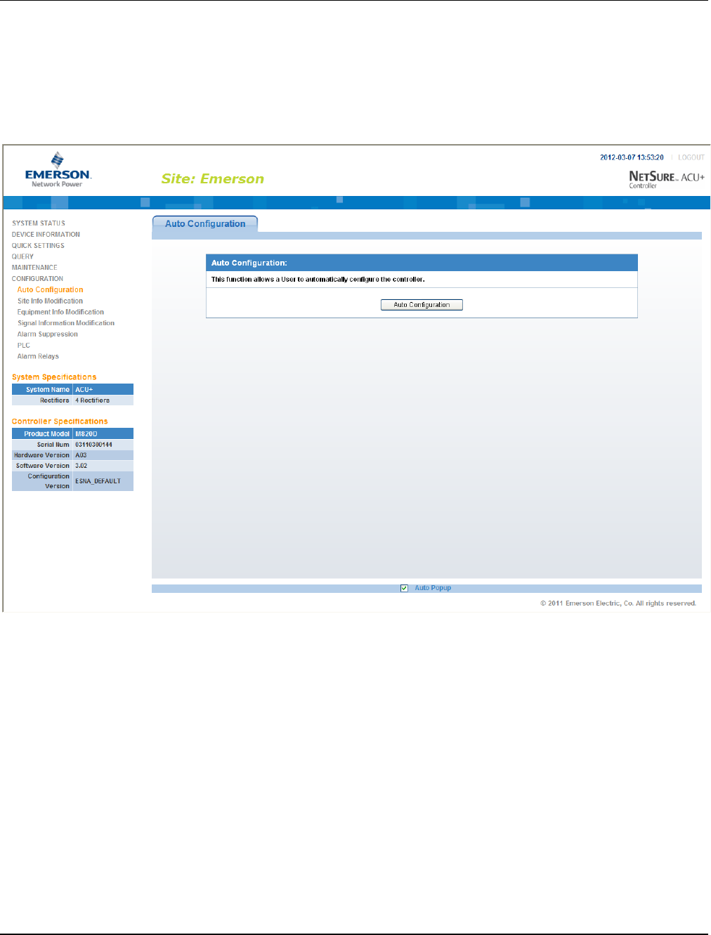
UM1M820BNA User Instructions
Issue AH, March 4, 2013 Spec No. 1M820BNA (Model M820B)
Spec No. 1M820DNA (Model M820D)
148 Chapter 4. WEB Interface Menus
This document is property of Emerson Network Power, Energy Systems, North America, Inc. and contains confidential and proprietary information owned by Emerson Network Power, Energy
Systems, North America, Inc. Any copying, use, or disclosure of it without the written permission of Emerson Network Power, Energy Systems, North America, Inc. is strictly prohibited.
4.8 Configuration Menu
4.8.1 Auto Configuration Sub-Menu
The auto configuration feature scans the system for intelligent equipment connected to the Controller
(such as SMDU, IB, and EIB) and configures these into the Controller automatically.
To start the auto configuration process, click on the "Auto Configuration" button.
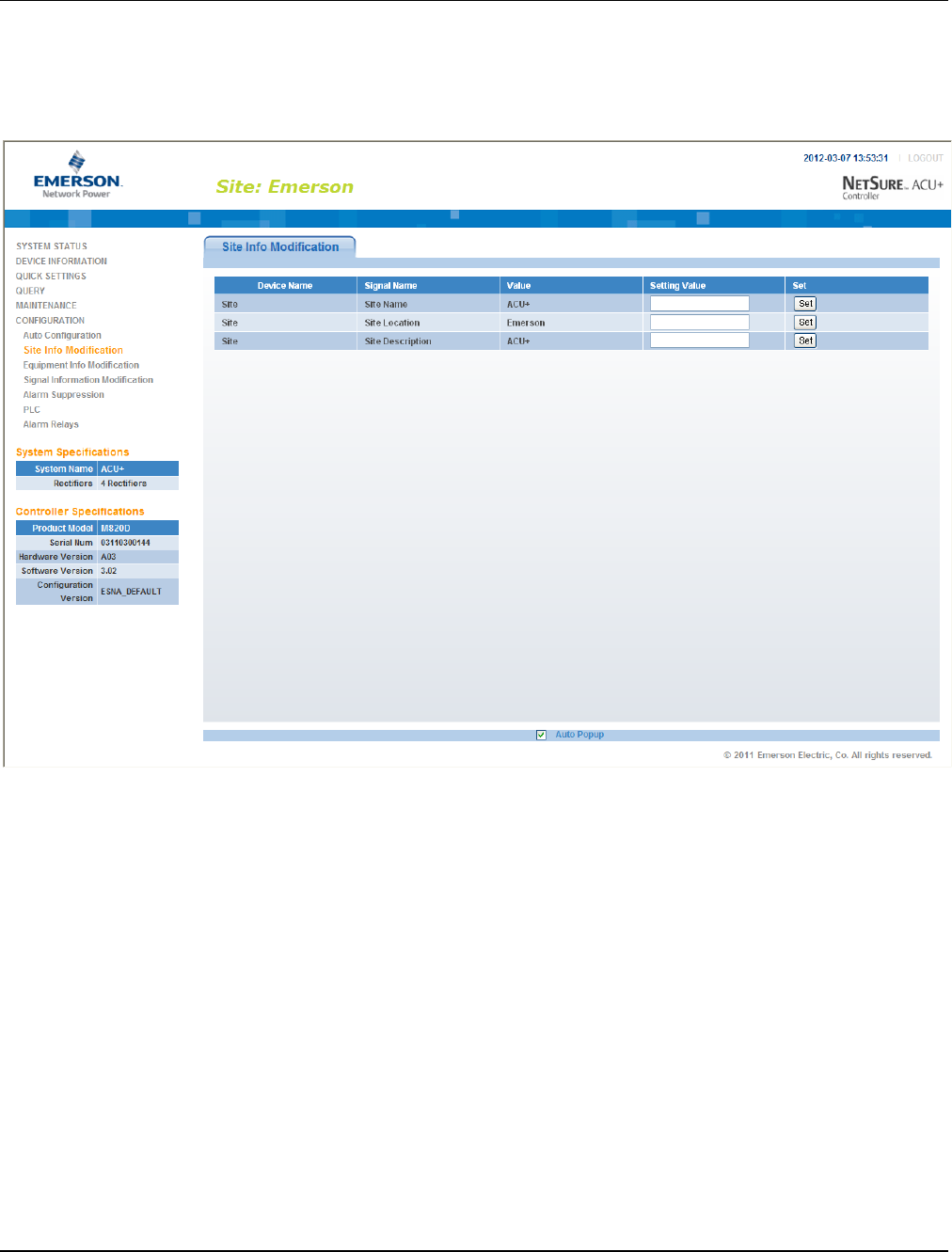
User Instructions UM1M820BNA
Spec No. 1M820BNA (Model M820B) Issue AH, March 4, 2013
Spec No. 1M820DNA (Model M820D)
Chapter 4. WEB Interface Menus 149
This document is property of Emerson Network Power, Energy Systems, North America, Inc. and contains confidential and proprietary information owned by Emerson Network Power, Energy
Systems, North America, Inc. Any copying, use, or disclosure of it without the written permission of Emerson Network Power, Energy Systems, North America, Inc. is strictly prohibited.
4.8.2 Site Information Modification Sub-Menu
Here you can add or change Site information. You can enter information such as a site name, site location,
and site description. Click on the "Set" button to store the Site information entered. After you change the
Site information you will need to reboot the controller to see the changes.
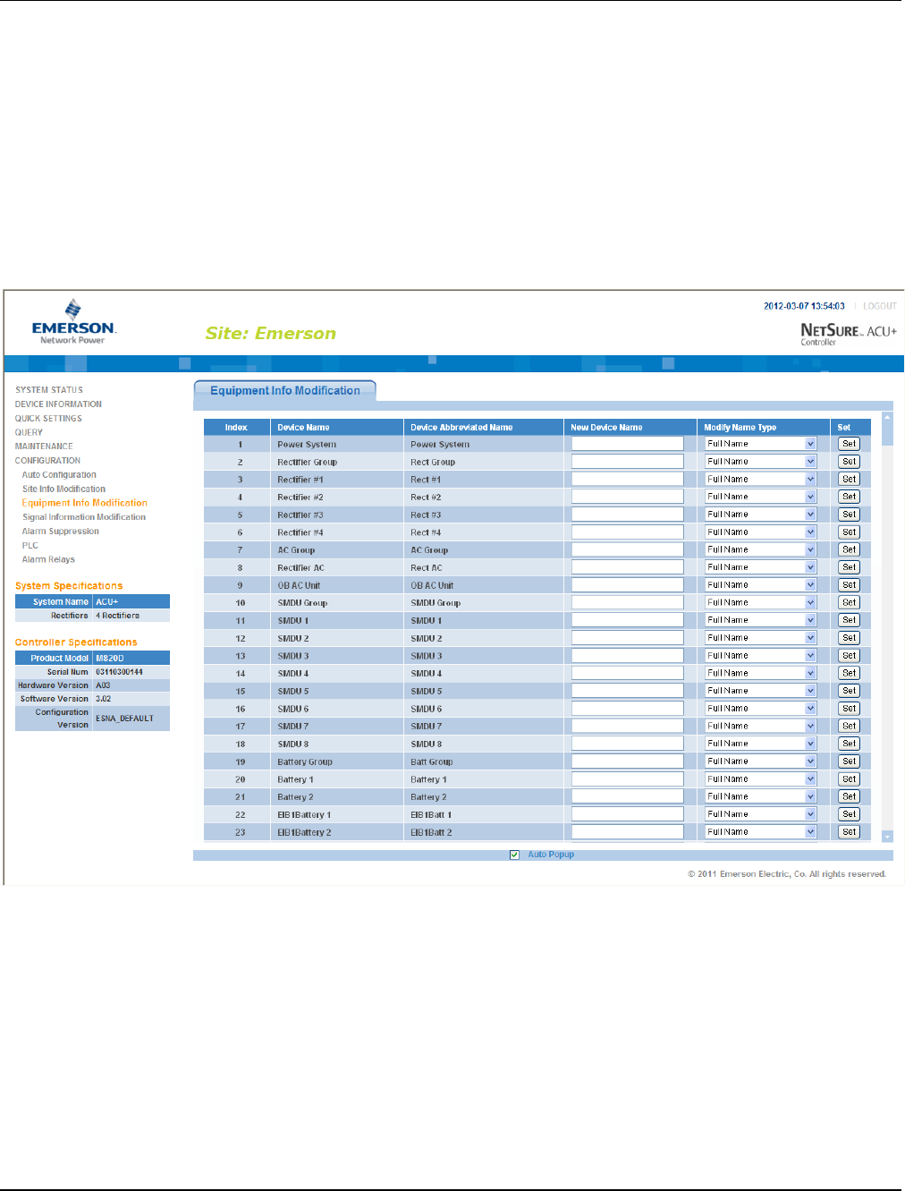
UM1M820BNA User Instructions
Issue AH, March 4, 2013 Spec No. 1M820BNA (Model M820B)
Spec No. 1M820DNA (Model M820D)
150 Chapter 4. WEB Interface Menus
This document is property of Emerson Network Power, Energy Systems, North America, Inc. and contains confidential and proprietary information owned by Emerson Network Power, Energy
Systems, North America, Inc. Any copying, use, or disclosure of it without the written permission of Emerson Network Power, Energy Systems, North America, Inc. is strictly prohibited.
4.8.3 Equipment Information Modification Sub-Menu
Here you can change the name of an equipment device connected to the Controller. Equipment devices
have two names. One is the “Device Full Name” and another is the “Device Abbreviated Name”. The
“Device Full Name” is displayed in the WEB Interface menus and the “Device Abbreviated Name” is
displayed in the local LCD display menus.
Enter the new device name in the “New Device Name” column and select what Device Name is to be
changed (“Device Full Name” or “Device Abbreviated Name”). Click on the "Set" button to save the new
name.
Device Full Name (32 characters maximum).
Device Abbreviated Name (15 characters maximum).

User Instructions UM1M820BNA
Spec No. 1M820BNA (Model M820B) Issue AH, March 4, 2013
Spec No. 1M820DNA (Model M820D)
Chapter 4. WEB Interface Menus 151
This document is property of Emerson Network Power, Energy Systems, North America, Inc. and contains confidential and proprietary information owned by Emerson Network Power, Energy
Systems, North America, Inc. Any copying, use, or disclosure of it without the written permission of Emerson Network Power, Energy Systems, North America, Inc. is strictly prohibited.
4.8.4 Signal Information Modification Sub-Menu
Here you can change the name of signals connected to the Controller. Signals have two names. One is
the “Signal Full Name” and another is the “Signal Abbreviated Name”. The “Signal Full Name” is displayed
in the WEB Interface menus and the “Signal Abbreviated Name” is displayed in the local LCD display
menus.
Enter the new signal name in the “New Name” column and select what Name is to be changed (“Signal
Full Name” or “Signal Abbreviated Name”). Click on the "Set" button to save the new name.
Signal Full Name (32 characters maximum).
Signal Abbreviated Name (15 characters maximum).
Note: If a signal is renamed it is recommended to retain enough information about the physical location
of the signal as possible. As an example, if you want to assign a name of 'Intrusion 6' to the signal
who's default name is 'DI1 Alarm' it could be labeled 'DI1 Intrusion 6'. This will help in physically
locating the wiring etc. related to the 'Intrusion 6' alarm. Alternately, the customer could label the
wiring and/or position that is related to the signal name.
Sample Signal Name Modification Procedure
The following procedure demonstrates how to change the “System Voltage” to “Bus Voltage”.
1) Select the equipment to which this signal belongs: Power System.
2) Select the signal type to which the signal belongs: Sample Signal.
3) Enter new signal name: Bus Voltage.

UM1M820BNA User Instructions
Issue AH, March 4, 2013 Spec No. 1M820BNA (Model M820B)
Spec No. 1M820DNA (Model M820D)
152 Chapter 4. WEB Interface Menus
This document is property of Emerson Network Power, Energy Systems, North America, Inc. and contains confidential and proprietary information owned by Emerson Network Power, Energy
Systems, North America, Inc. Any copying, use, or disclosure of it without the written permission of Emerson Network Power, Energy Systems, North America, Inc. is strictly prohibited.
4) Select the type of signal name to be changed: “Signal Full Name” or “Signal Abbreviated Name”.
5) Click the “Set” button.
For alarm signals, you can also change the alarm level (severity) for the alarm signal.
In the second step in the above procedure, select “Alarm Signal”, then the alarm signal name and alarm
level are displayed. Select “New alarm level” and click “Set” to change the alarm level (severity) of this
alarm signal.

User Instructions UM1M820BNA
Spec No. 1M820BNA (Model M820B) Issue AH, March 4, 2013
Spec No. 1M820DNA (Model M820D)
Chapter 4. WEB Interface Menus 153
This document is property of Emerson Network Power, Energy Systems, North America, Inc. and contains confidential and proprietary information owned by Emerson Network Power, Energy
Systems, North America, Inc. Any copying, use, or disclosure of it without the written permission of Emerson Network Power, Energy Systems, North America, Inc. is strictly prohibited.
4.8.5 Alarm Suppressing Sub-Menu
Here you can modify the Alarm Suppression relationships of an alarm signal.
Alarm Suppression Explanation: If Alarm A suppresses Alarm B, when Alarm A occurs, Alarm B will not
be reported even if the conditions of Alarm B are met. For example, AC failure alarm will suppress AC low
voltage alarm. When AC failure occurs, the alarm conditions for both AC failure alarm and AC low voltage
alarm are met, and both alarms should be reported. However, since the AC failure alarm suppresses the
AC low voltage alarm, only AC failure alarm is displayed in the alarm list.
To configure Alarm Suppression, first select the device to which the alarm signal belongs. This displays all
the alarm signals of this device.
Locate the alarm signal to be configured for Alarm Suppression and click on the “Modify” button for this
alarm signal.
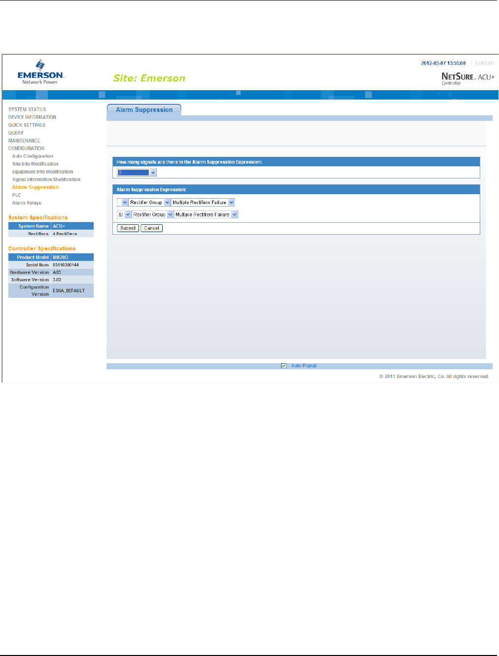
UM1M820BNA User Instructions
Issue AH, March 4, 2013 Spec No. 1M820BNA (Model M820B)
Spec No. 1M820DNA (Model M820D)
154 Chapter 4. WEB Interface Menus
This document is property of Emerson Network Power, Energy Systems, North America, Inc. and contains confidential and proprietary information owned by Emerson Network Power, Energy
Systems, North America, Inc. Any copying, use, or disclosure of it without the written permission of Emerson Network Power, Energy Systems, North America, Inc. is strictly prohibited.
The following screen appears which allows you to configure the Alarm Suppression Expression. In this
screen, you can select the signals in the Alarm Suppression Expression and enter the logic relationship
before the alarm signal (Logic AND &, Logic OR |, Logic NO!).
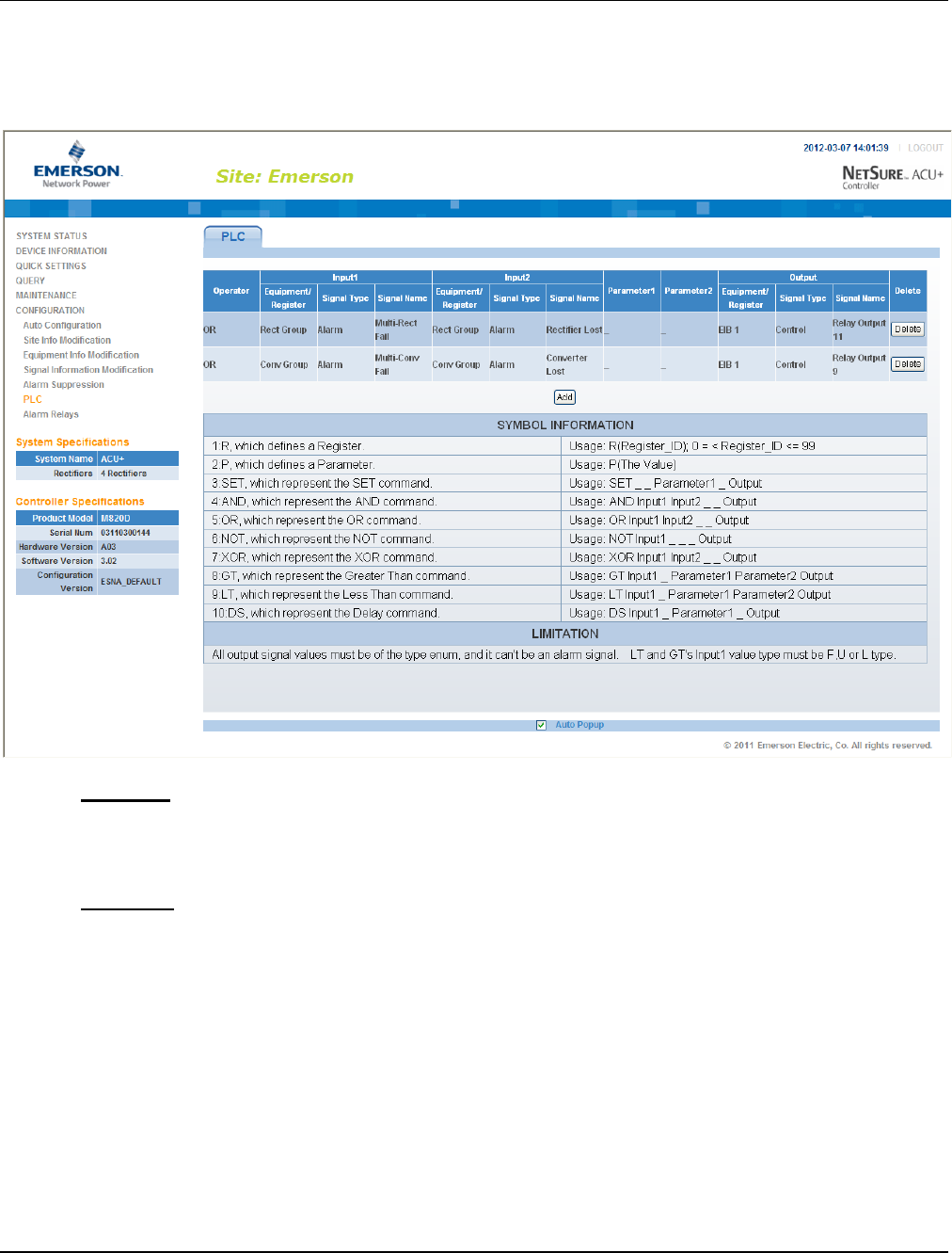
User Instructions UM1M820BNA
Spec No. 1M820BNA (Model M820B) Issue AH, March 4, 2013
Spec No. 1M820DNA (Model M820D)
Chapter 4. WEB Interface Menus 155
This document is property of Emerson Network Power, Energy Systems, North America, Inc. and contains confidential and proprietary information owned by Emerson Network Power, Energy
Systems, North America, Inc. Any copying, use, or disclosure of it without the written permission of Emerson Network Power, Energy Systems, North America, Inc. is strictly prohibited.
4.8.6 PLC Sub-Menu
Allows you to configure the PLC functions of the Controller.
The following shows the PLC sub-menu.
Operation
The PLC function normally runs every 10 seconds. It starts by executing the first line and stores the result
in the output signal/register. Then executes the next line and continues executing line by line until it
reaches the end. The PLC function will be stopped if the ACU+ is set to Manual Mode.
Procedure
1) Click the ADD button and the window below is shown.
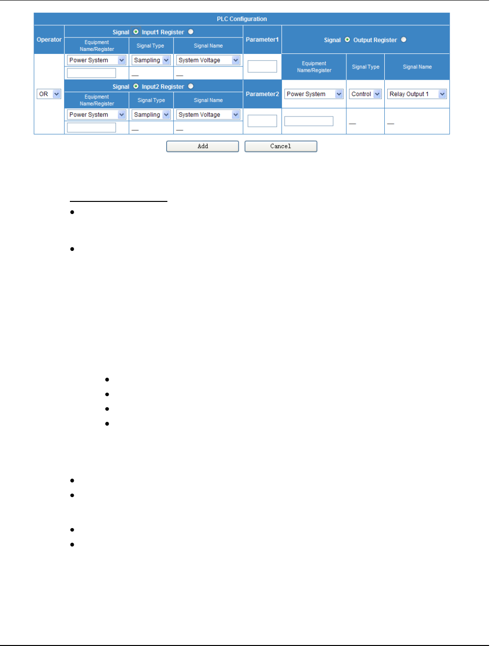
UM1M820BNA User Instructions
Issue AH, March 4, 2013 Spec No. 1M820BNA (Model M820B)
Spec No. 1M820DNA (Model M820D)
156 Chapter 4. WEB Interface Menus
This document is property of Emerson Network Power, Energy Systems, North America, Inc. and contains confidential and proprietary information owned by Emerson Network Power, Energy
Systems, North America, Inc. Any copying, use, or disclosure of it without the written permission of Emerson Network Power, Energy Systems, North America, Inc. is strictly prohibited.
Column Descriptions
Operator: The Operator column selects the type of function that will be performed. The list of
Operators is shown in the Symbol Information table (from line 3 and down) in the previous PLC
screen.
Input 1: The Input 1 column is divided into the following three sub-columns.
a) EquipName/Register: This column shows the Equipment that the signal to be selected in
c) below is associated with. (Equipment is not necessarily connected to a physical device.
An Equipment can be connected to several physical devices and vice versa.)
The Equipment can be replaced by a Register. Every Register is given a unique number
between 0 and 99. A Register works as a temporary storage place that will be cleared after
every run of the PLC function.
b) Signal Type: This column shows the type of signal to be selected in c) below.
The ACU+ has four different signal types:
Sample (measured or calculated values, status).
Control (control of different functions or events).
Setting (different kind of settings).
Alarm (alarms, these signals will only be activated if the alarm category is set to
anything else than NA).
c) Signal Name: You select the signal from this column. Signals that are shown in the
drop-down list box are based on your selections in a) and b) above.
Input 2: (See Input 1 above.)
Param 1: This column shows if any parameter is used.
A parameter is just a way to enter a value, which can be used in compares with signals.
Param 2: (See Param 1 above.)
Output: The Output column is divided in three sub-columns, which has the same information
as for the Inputs.
2) Choose the type of Operator. The web page will disable some boxes that are not applicable for the
type of Operator.
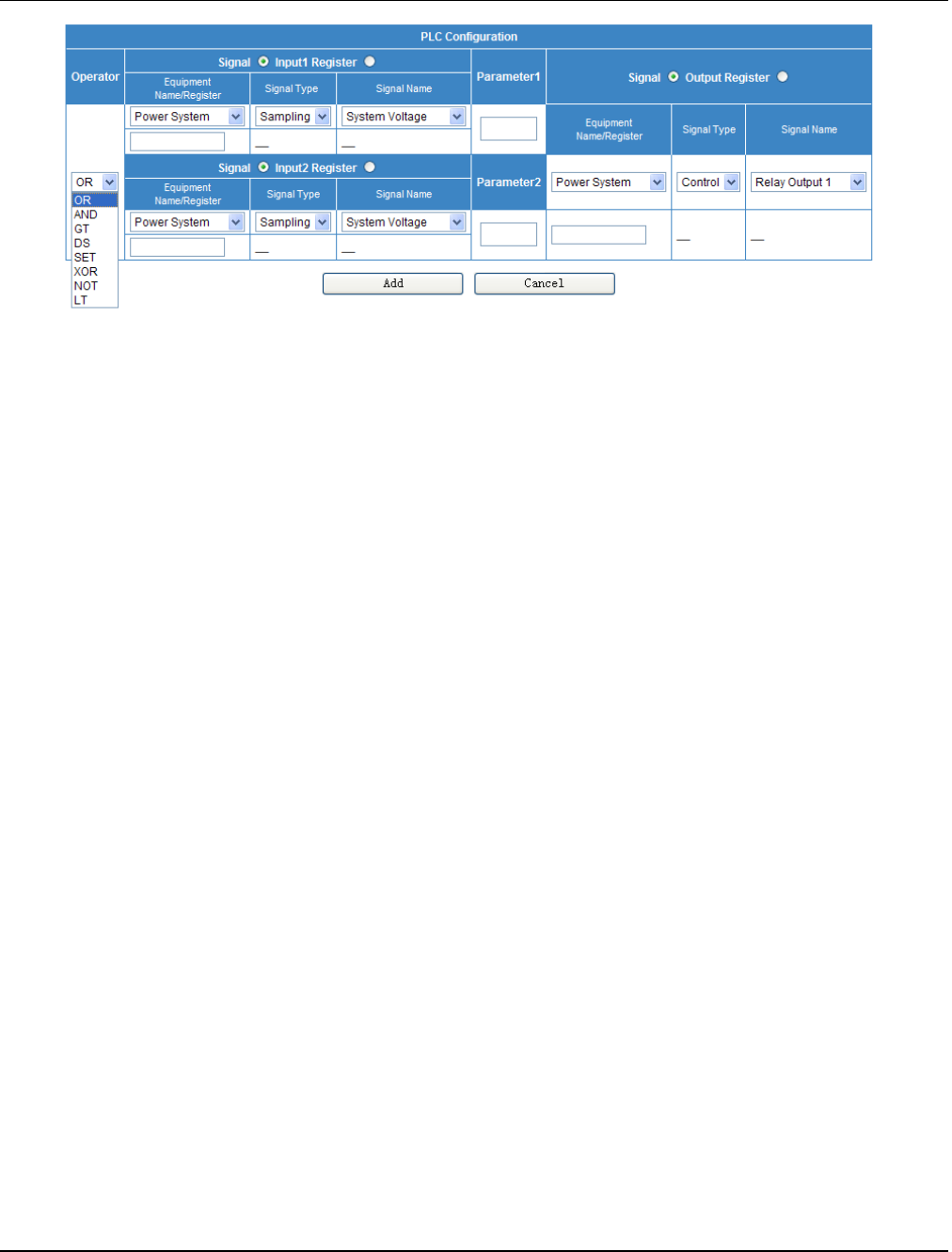
User Instructions UM1M820BNA
Spec No. 1M820BNA (Model M820B) Issue AH, March 4, 2013
Spec No. 1M820DNA (Model M820D)
Chapter 4. WEB Interface Menus 157
This document is property of Emerson Network Power, Energy Systems, North America, Inc. and contains confidential and proprietary information owned by Emerson Network Power, Energy
Systems, North America, Inc. Any copying, use, or disclosure of it without the written permission of Emerson Network Power, Energy Systems, North America, Inc. is strictly prohibited.
3) Select Signal or Register for Input 1.
4) Enter either the register number or choose the equipment, signal type, and signal name. The format
for entering a register is R(x), where x is the number of the register.
5) Setup Input 2 in the same way as Input 1 if it’s not disabled.
6) Enter Param 1 and Param 2 if they are not disabled. The format for entering a parameter is P(x),
where x is the value.
7) Select Signal or Register for Output.
8) Enter either the register number or choose the equipment, signal type, and signal name.
9) Click the ADD button in the bottom of the window.
10) Reboot the ACU+. See “4.7.7. Restore Factory Defaults Sub-Menu”.
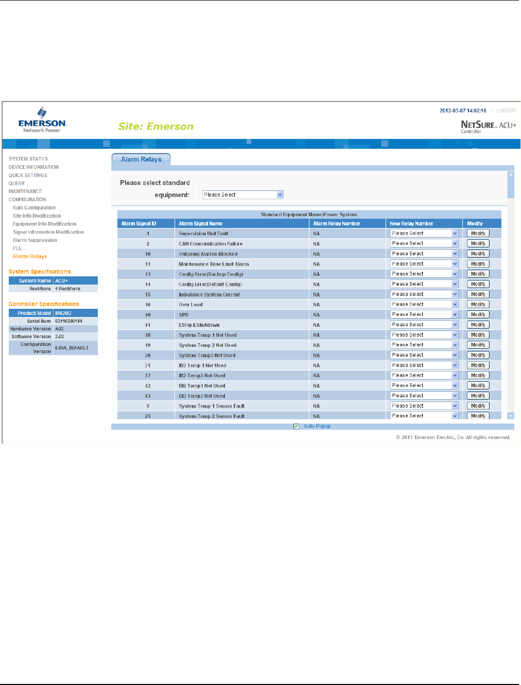
UM1M820BNA User Instructions
Issue AH, March 4, 2013 Spec No. 1M820BNA (Model M820B)
Spec No. 1M820DNA (Model M820D)
158 Chapter 4. WEB Interface Menus
This document is property of Emerson Network Power, Energy Systems, North America, Inc. and contains confidential and proprietary information owned by Emerson Network Power, Energy
Systems, North America, Inc. Any copying, use, or disclosure of it without the written permission of Emerson Network Power, Energy Systems, North America, Inc. is strictly prohibited.
4.8.7 Alarm Relay Sub-Menu
Allows you to map system alarms to the alarm relays.
Select the device to display the system alarms associated to it. Also displayed is the alarm relay number
assigned to this alarm. To modify the alarm relay number, click on the “Modify” button for that alarm signal.
“NA” means there is no related relay number.

User Instructions UM1M820BNA
Spec No. 1M820BNA (Model M820B) Issue AH, March 4, 2013
Spec No. 1M820DNA (Model M820D)
Chapter 5. Accessing the Controller via a Network Management System (NMS) 159
This document is property of Emerson Network Power, Energy Systems, North America, Inc. and contains confidential and proprietary information owned by Emerson Network Power, Energy
Systems, North America, Inc. Any copying, use, or disclosure of it without the written permission of Emerson Network Power, Energy Systems, North America, Inc. is strictly prohibited.
CHAPTER 5. ACCESSING THE CONTROLLER
VIA A NETWORK MANAGEMENT SYSTEM (NMS)
5.1 General
The Controller has an SNMP agent function.
Users can use a Network Management System (NMS) to do following operations:
Query the operation status and input/output signals of the devices connected to the Controller.
Browse the active alarms.
When the Controller generates alarms, the SNMP agent can notify the preset NMS through TRAPS
automatically.
5.2 NMS Supported by SNMP Agent
The SNMP agent of the Controller supports SNMPv2c.
All the NMS that supports SNMPv2c can be used to access the Controller. The NMS includes HP
OpenView, IBM NetView, Novell ManageWise, SunNet Manager and so on. SNMP is a technology used
for network management. The technology is based on implementing an information base called MIB
(Managed Information Base). This MIB contains parameters that are of interest from a management
perspective. All LAN connected equipment that support SNMP also support a default MIB called MIB-II.
The SNMP Agent responds to requests received via the SNMP protocol and also actively sends TRAPS
to a specified manager when certain MIB values change state. This is used to actively inform a manager
when an alarm situation is recognized.
5.3 MIB Installation
5.3.1 Installation
The Controller’s MIB is named "Netsure_ESNA.mib". Contact your Emerson representative for the
location on the Web to download the MIB file.
Use the MIB loading function of NMS to load the MIB database, refer to the corresponding NMS User
Manual for the detailed loading method.
5.3.2 Contents of the Controller’s MIB
The contents of the MIB supported by the Controller’s SNMP agent and the OID are listed in Table 5. For
the details, refer to the file named "Netsure_ESNA.mib".

UM1M820BNA User Instructions
Issue AH, March 4, 2013 Spec No. 1M820BNA (Model M820B)
Spec No. 1M820DNA (Model M820D)
160 Chapter 5. Accessing the Controller via a Network Management System (NMS)
This document is property of Emerson Network Power, Energy Systems, North America, Inc. and contains confidential and proprietary information owned by Emerson Network Power, Energy
Systems, North America, Inc. Any copying, use, or disclosure of it without the written permission of Emerson Network Power, Energy Systems, North America, Inc. is strictly prohibited.
Ident Group
Controller Ident Group
identManufacturer
The name of the equipment manufacturer.
R
identModel
The manufacturers model designation of the power system.
R
identControllerFirmwareVersion
The firmware (software) version of the Controller.
R
identName
The name of the power plant. This object should be set by the
administrator.
R/W
System Group
Controller System Value Group
systemStatus
Status of the complete plant (highest alarm). One of...
(1) unknown - status has not yet been defined
(2) normal - there are no activated alarms
(3) warning - OA, lowest level of 'abnormal' status
(4) minor - A3
(5) major - MA
(6) critical - CA, highest level of 'abnormal' status
(7) unmanaged
(8) restricted
(9) testing
(10) disabled
R
systemVoltage
System voltage, stored as mV.
R
systemCurrent
System current, stored as mA.
R
systemUsedCapacity
Used capacity, stored as percentage of the total capacity .
R
psBattery Group
Power System Battery Group
psBatteryVoltage
Battery voltage, stored as mV.
R
psBatteryCurrent
Battery current, stored as mA.
R
psInput Group
Power System Input Group
psInputLineAVoltage
The AC line A voltage, stored as mV.
R
psInputLineBVoltage
The AC line B voltage, stored as mV.
R
psInputLineCVoltage
The AC line C voltage, stored as mV.
R
psTemperature Group
Power System Temperature Group
psTemperature1
The first route temperature, stored as 0.001 Celsius degree.
R
psTemperature2
The second route temperature, stored as 0.001 Celsius degree.
R

User Instructions UM1M820BNA
Spec No. 1M820BNA (Model M820B) Issue AH, March 4, 2013
Spec No. 1M820DNA (Model M820D)
Chapter 5. Accessing the Controller via a Network Management System (NMS) 161
This document is property of Emerson Network Power, Energy Systems, North America, Inc. and contains confidential and proprietary information owned by Emerson Network Power, Energy
Systems, North America, Inc. Any copying, use, or disclosure of it without the written permission of Emerson Network Power, Energy Systems, North America, Inc. is strictly prohibited.
psStatusCommunication
The status of communication with the Power System.
(1) unknown
(2) normal
(3) interrupt indicates some errors occurred between Power System
and agent
R
psStatusBatteryMode
The status of battery modes.
(1) unknown
(2) FloatCharging
(3) ShortTest
(4) EqualizeChargingForTest
(5) ManualTesting
(6) PlanTesting
(7) ACFailTesting
(8) ACFail
(9) ManualEqualizeCharging
(10) AutoEqualizeCharging
(11) CyclicEqualizeCharging
(12) MasterEqualizeCharging
(13) MasterBatteryTesting
R
SM Series Group
Supervisory Module Group
psSMACNumber
The number of SM AC module.
R
psSMBATNumber
The number of SM BAT module.
R
psSMIONumber
The number of SM IO module.
R
Alarm Trap Group
Controller Alarm Trap Group
alarmLastTrapNo
The sequence number of last submitted alarm trap.
R
alarmTrapTable
(alarmTrapEntry)
Table holding information about the submitted alarm traps.
alarmTrapEntry is the entry (conceptual row) in the alarmTrapTable.
R
alarmTrapNo
The unique sequence number of this alarm trap.
R
alarmTime
Date and time when event occurred (local time), including timezone if
supported by Controller.
R
alarmStatusChange
The type of alarm change. One of...
(1) activated
(2) deactivated
R
alarmSeverity
The severity of the alarm. One of...
(1) warning - OA, lowest level of alarm severity
(2) minor - A3
(3) major - MA
(4) critical - CA, highest level of alarm severity
R
alarmDescription
Free-text description of alarm.
R

UM1M820BNA User Instructions
Issue AH, March 4, 2013 Spec No. 1M820BNA (Model M820B)
Spec No. 1M820DNA (Model M820D)
162 Chapter 5. Accessing the Controller via a Network Management System (NMS)
This document is property of Emerson Network Power, Energy Systems, North America, Inc. and contains confidential and proprietary information owned by Emerson Network Power, Energy
Systems, North America, Inc. Any copying, use, or disclosure of it without the written permission of Emerson Network Power, Energy Systems, North America, Inc. is strictly prohibited.
alarmType
Alarm type, i.e. an integer specifying the type of alarm.
R
Traps
Alarm Traps Info
--
The SNMP agent can send the active alarms to the specified NMS
and the User can define the lowest severity of the NMS accepted
alarms.
--
Table 5
Contents of the Controller’s MIB
In Table 5, R means OID is read-only (GET), and R/W means OID can be read and modified (GET/SET).

User Instructions UM1M820BNA
Spec No. 1M820BNA (Model M820B) Issue AH, March 4, 2013
Spec No. 1M820DNA (Model M820D)
Chapter 5. Accessing the Controller via a Network Management System (NMS) 163
This document is property of Emerson Network Power, Energy Systems, North America, Inc. and contains confidential and proprietary information owned by Emerson Network Power, Energy
Systems, North America, Inc. Any copying, use, or disclosure of it without the written permission of Emerson Network Power, Energy Systems, North America, Inc. is strictly prohibited.
5.4 Accessing the Controller through an NMS
5.4.1 Apply Administrative Authority
In order to use NMS to manage the devices connected to the Controller, the administrative authority
needs to be applied for the NMS, that is, add the NMS information to the access list of SNMP agent.
Add NMS through Web Browser
Refer to “Chapter 4. WEB Interface Menus” for the method of adding NMS.
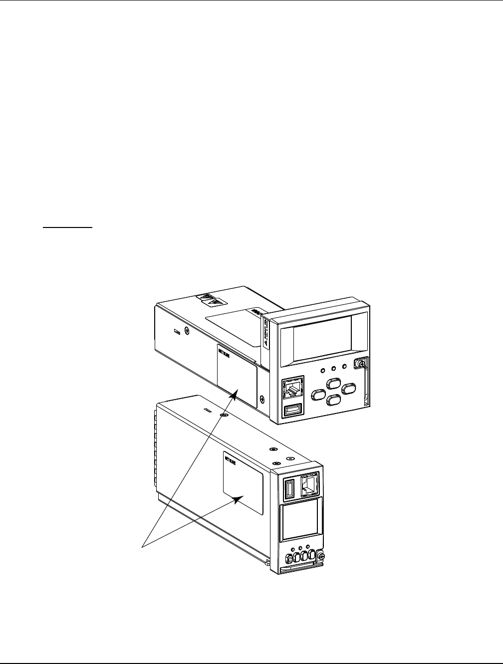
UM1M820BNA User Instructions
Issue AH, March 4, 2013 Spec No. 1M820BNA (Model M820B)
Spec No. 1M820DNA (Model M820D)
164 Chapter 6. Replacement Procedures
This document is property of Emerson Network Power, Energy Systems, North America, Inc. and contains confidential and proprietary information owned by Emerson Network Power, Energy
Systems, North America, Inc. Any copying, use, or disclosure of it without the written permission of Emerson Network Power, Energy Systems, North America, Inc. is strictly prohibited.
CHAPTER 6. REPLACEMENT PROCEDURES
6.1 ACU+ Controller Replacement
Warning: ACU+ CONTROLLER HANDLING.
Installation or removal of the ACU+ Controller requires careful handling. To avoid
possibility of ACU+ Controller damage from static discharge, a static wrist strap
grounded through a one megohm resistor should always be worn when handling the
ACU+ Controller. ESD-protective packaging material must also be used when
carrying/shipping the ACU+ Controller.
Note: Depending on your network security settings, when you remove a device that is connected to your
network and assign the same IP address to the replacement device, you may not be allowed to
communicate with the replacement device over the network. Contact your network administrator
for assistance.
The ACU+ Controller is hot swappable. It can be removed and installed with the system operating and
without affecting the output bus.
Procedure
1) Before performing this procedure, ensure the replacement ACU+ Controller contains the same
configuration file as the existing ACU+ Controller. Refer to the Configuration Label on the side of
the replacement ACU+ Controller for the Configuration Part Number. If the existing Controller is
operational, navigate the menus to view its configuration file (MAIN SCREEN/ESC/ENT/ENT).
Figure 9
ACU+ Controller Configuration Label Location
2) Performing this procedure may activate external alarms. Do one of the following. If possible,
disable these alarms. If these alarms cannot be easily disabled, notify the appropriate personnel to
disregard any future alarms associated with this system while this procedure is being performed.
Configuration File
Part N umber Label
M820D
M820B
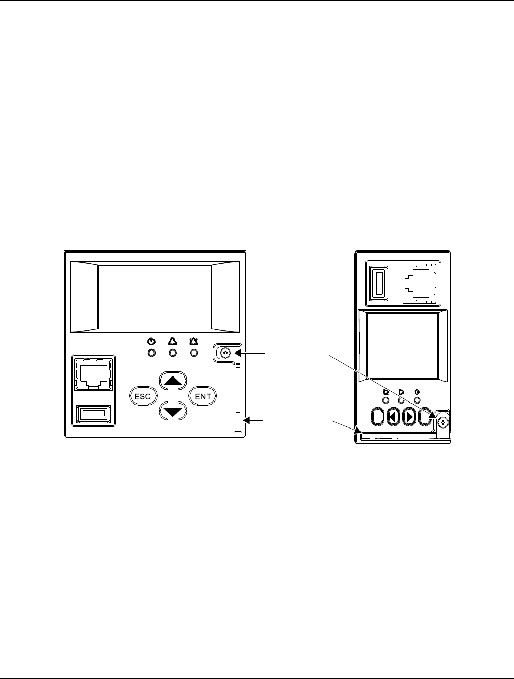
User Instructions UM1M820BNA
Spec No. 1M820BNA (Model M820B) Issue AH, March 4, 2013
Spec No. 1M820DNA (Model M820D)
Chapter 6. Replacement Procedures 165
This document is property of Emerson Network Power, Energy Systems, North America, Inc. and contains confidential and proprietary information owned by Emerson Network Power, Energy
Systems, North America, Inc. Any copying, use, or disclosure of it without the written permission of Emerson Network Power, Energy Systems, North America, Inc. is strictly prohibited.
3) Connect an approved grounding strap to your wrist. Attach the other end to a suitable ground.
4) Loosen the captive fastener securing the latch mechanism to the front of the ACU+ Controller. Pull
the latch mechanism away from the ACU+ Controller (this will retract the latch mechanism located
on the bottom of the ACU+ Controller). This unlocks the ACU+ Controller from the shelf. Refer to
Figure 10.
5) Slide the ACU+ Controller completely from the shelf.
6) Loosen the captive fastener securing the latch mechanism to the front of the replacement ACU+
Controller. Pull the latch mechanism away from the ACU+ Controller (this will retract the latch
mechanism located on the bottom of the ACU+ Controller).
7) Slide the ACU+ Controller completely into its mounting position.
8) Push the latch mechanism into the front panel of the ACU+ Controller, and secure by tightening the
captive fastener. This locks the ACU+ Controller securely to the shelf.
9) Wait for the Controller to finish booting and verify that the complete system operates normally.
10) Enable the external alarms, or notify appropriate personnel that this procedure is finished.
11) Ensure that there are no local or remote alarms active on the system.
Figure 10
Latch Mechanism on the ACU+ Controller
Captive Fastener
Latch Mechanism
ESC
ENT
M820D M820B

UM1M820BNA User Instructions
Issue AH, March 4, 2013 Spec No. 1M820BNA (Model M820B)
Spec No. 1M820DNA (Model M820D)
166 Chapter 7. Specifications
This document is property of Emerson Network Power, Energy Systems, North America, Inc. and contains confidential and proprietary information owned by Emerson Network Power, Energy
Systems, North America, Inc. Any copying, use, or disclosure of it without the written permission of Emerson Network Power, Energy Systems, North America, Inc. is strictly prohibited.
CHAPTER 7. SPECIFICATIONS
Input Voltage Range: 19 to 60 VDC.
Power Consumption: 5W.
Operating Temperature Range: -40°C (-40°F) to +75°C (+167°F).
Humidity: Capable of operating in an ambient relative humidity range of 0% to 90%, non-condensing.
Dimensions:
Model M820B: 42mm (H) x 86.6mm (W) x 211.5mm (D)
1.65” (H) x 3.41” (W) x 8.33” (D)
Model M820D: 86.6mm (H) × 86.8mm (W) × 211.5mm (D)
3.41” (H) x 3.41” (W) x 8.33” (D)
Weight: < 1kg (2.2 lbs).
Front Panel Display: LCD with 4 x 16 (Model M820D) or 8 x 16 (Model M820B) characters.
Indicators:
Status (Green)
Minor Alarm (Yellow)
Critical / Major Alarm (Red)
Local and Remote Access Passwords: Refer to “2.2 Passwords and Access Levels”.
Inputs and Outputs: Connection points provided on ACU+ Interface Board(s) mounted in the system.
Refer to your system documentation.
Factory Default Setpoints: Refer to the Configuration Drawing (C-drawing) furnished with your system
for a list of factory default values.

User Instructions UM1M820BNA
Spec No. 1M820BNA (Model M820B) Issue AH, March 4, 2013
Spec No. 1M820DNA (Model M820D)
Chapter 7. Specifications 167
This document is property of Emerson Network Power, Energy Systems, North America, Inc. and contains confidential and proprietary information owned by Emerson Network Power, Energy
Systems, North America, Inc. Any copying, use, or disclosure of it without the written permission of Emerson Network Power, Energy Systems, North America, Inc. is strictly prohibited.
This page is intentionally blank.

UM1M820BNA User Instructions
Issue AH, March 4, 2013 Spec No. 1M820BNA (Model M820B)
Spec No. 1M820DNA (Model M820D)
168 Revision Record
This document is property of Emerson Network Power, Energy Systems, North America, Inc. and contains confidential and proprietary information owned by Emerson Network Power, Energy
Systems, North America, Inc. Any copying, use, or disclosure of it without the written permission of Emerson Network Power, Energy Systems, North America, Inc. is strictly prohibited.
REVISION RECORD
Issue
Change
Number
(ECO)
Description of Change
AA
LLP214923
New
AB
LLP215392
Revised for version 2.23.
AC
LLP215822
Revised for version 2.25.
AD
LLP216384
Revised for Version 3.00.
AE
LLP216700
Revised for Version 3.02.
AF
LLP217311
Revised for Version 3.04.
Section “2.5.36 Setting External Shunts (connected to the SM-DU+
Assembly)” added.
AG
LLP217741
Revised for Version 4.00 (Lithium Ion Battery Configuration support).
AH
LLP218449
Revised for Version 4.02 (Converter Menus Updated).
NetPerform™ Optimization Services
At Emerson Network Power, we understand the importance of reliable equipment – it’s critical to both your business and your
bottom line. That is why we offer a wide array of services to meet all of your network infrastructure needs.
Customer Service
[1,2]
Customer Support Center
Account Management
[2]
Spare Parts
DC Power Depot Repair
Technical Support
[1]
[2]
For More Information
To learn more about service offerings from Emerson Network Power, please contact your sales representative,
call 1-800-800-1280 option 7, email ES.Services@Emerson.com or visit EmersonNetworkPower.com/EnergySystems.