Emerson S200 Series Pressure Reducing Regulators Installation Guide S200_IG_done.p65
2015-03-30
: Emerson Emerson-S200-Series-Pressure-Reducing-Regulators-Installation-Guide-681344 emerson-s200-series-pressure-reducing-regulators-installation-guide-681344 emerson pdf
Open the PDF directly: View PDF ![]() .
.
Page Count: 6

S200 Series
D400007XENG
Installation Guide
English – May 2002
www.FISHERregulators.com
Introduction
This installation guide provides instructions for installation,
startup, and adjustment. To receive a copy of the instruction
manual, contact your local Fisher Sales
Office or Sales Representative or view a copy at
www.FISHERregulators.com. For further information refer to:
• Type S201 and S202 Instruction Manual, form 5171,
D400007X012
• Type S201P, S201PK, and S202P Instruction Manual,
form 5172, D400009X012
• Type S203, S203H, and S203P1-P3 Instruction Manual,
form 2216, D400010X1012
• Types S204 and S206 Instruction Manual, form 1749,
D400011X012
• Types S208 and S209 Instruction Manual, form5412,
D102247X012
P.E.D. Categories
This product may be used as a safety accessory with
pressure equipment in the following Pressure Equipment
Directive 97/23/EC categories. It may also be used out-
side of the Pressure Equipment Directive using sound
engineering practice (SEP) per table below.
EZISTCUDORPSEIROGETACEPYTDIULF
05,05x04,04,23ND
)2,2x2/1-1,2/1-1,4/1-1( I1
Specifications
Available Constructions (See table 1)
S201: Basic construction without internal relief for
5 to 75 mbar (2 to 30-inches w.c.) outlet pressures
S201H: S201 with a heavy diaphragm plate for 0,069
to 0,34 bar (1 to 5 psig ) outlet pressures
S201K: S201 with a heavy diaphragm plate for 0,14
to 0,69 bar (2 to 10 psig) outlet pressures
S201P: S201 with downstream control line connec-
tion and O-ring stem seal for external pressure
registration
S201PK: Combination of S201K and S201P
S202, S202H, S202P: S201, S201H, and S201P
constructions with internal relief
S203, S203H, S203P: S201, S201H, and S201P
constructions with “True” monitor regulator to
provide overpressure protection. Available in Cast
iron body only.
S204, S204H: S201 and S201H constructions with
a low outlet pressure shutoff. Available in Cast
iron body only.
S206, S206H: S202 and S202H constructions with
a low outlet pressure shutoff with internal relief.
Available in Cast iron body only.
S208, S208H, S208P, S208K, S208PK: S201,
S201H, S201P, S201K, and S201PK constructions
with a Type VSX-2 slam-shut device to provide over-
pressure (OPSO) or over and underpressure (UPSO)
protection. Available in Ductile iron body only.
S209, S209H, S209P: S202, S202H, and S202P
constructions with a Type VSX-2 slam-shut device
to provide overpressure (OPSO) or over and under-
pressure (UPSO) protection. Available in Ductile
iron body only.
Body Sizes and End Connection Styles(1)
See table 2
Minimum and Maximum Inlet Pressures(1)
Maximum Emergency (Body Rating) Inlet
Pressure: 12 bar (175 psig)
Maximum Operating Inlet Pressure: See table 4
Types S204 and S206 Minimum Inlet Pressure
Required to Prevent Shutoff: See figure 1
Maximum Outlet Pressure (Casing)(1)
1,0 bar (15 psig)
Maximum Operating Outlet Pressure to Avoid Internal
Part Damage(1)
Light Diaphragm Plate: 0,14 bar (2 psi) above
outlet pressure setting
Heavy Diaphragm Plate: 0,21 bar (3 psi) above
outlet pressure setting
Outlet Pressure Ranges(1)
See table 3
Integral Monitor Performance(1)
See table 5
Internal Relief Performance(1)
Internal relief valve opens at 20 to 69 mbar
(7 to 28-inches w.c.) above outlet setting, depending
on control spring
Type VSX-2 Trip Pressure Ranges(1)
See table 6
Proof Test Pressure
All Pressure Retaining Components have been
proof tested per Directive 97/23/EC - Annex 1,
Section 7.4
Maximum Temperature Capabilities(1)
Nitrile (NBR):
–29° to 66°C (–20° to 150°F)
Fluoroelastomer (FKM):
–18° to 93°C (0° to 200°F)
(Upper temperature limitation due to nylon flappers)
Type VSX-2:
–29° to 60°C (–20° to 140°F)
1. The pressure/temperature limits in this installation guide and any applicable
standard or code limitation should not be exceeded.
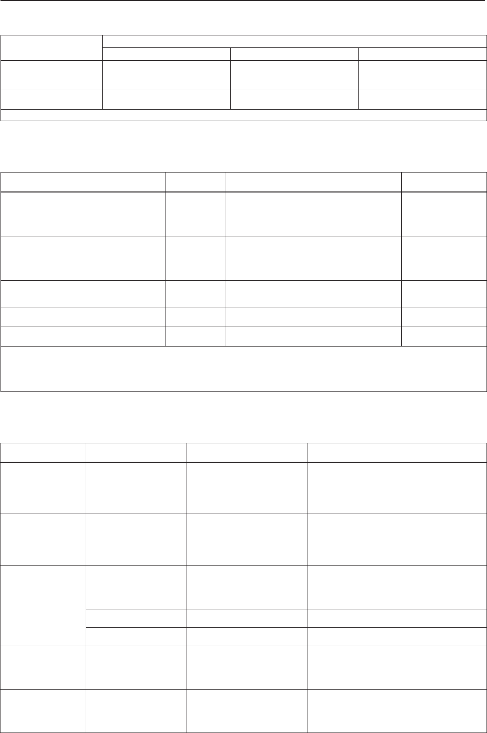
SLAIRETAMYDOB
REBMUNEPYT
norItsaC XXXXXXXXXXXXXXX
norIelitcuD XXXXXXXX XXXXXXXX
leetS XXXXXXXX
S201
S201H
S201K
S201P
S201PK
S202
S202H
S202P
S203
S203H
S203P
S204
S204H
S206
S206H
S208
S208H
S208K
S208P
S208PK
S209
S209H
S209P
Table 1. Available Constructions
S200 Series
2
)SEHCNI(ND,EZISYDOB ELYTSNOITCENNOCDNE
norItsaCnorIelitcuDleetS
)4/1-1(23
)2/1-1(04
)2x2/1-1(05x04
PSB,TPN
PSB,TPN
---
---
PSB,TPN
PSB,TPN
---
PSB,TPN
---
)2(05 FF521ssalCISNAro;PSB;TPN
)1(
,
degnalfFR052
roFF521ssalCISNA;PSB;TPN
degnalf61-01NPro;degnalfFR052
roFR051ssalCISNA;PSB;TPN
degnalf61-01NPro;degnalfFR003
.)sehcni-01(mm452ro)sehcni-5.7(mm191foecaf-ot-ecafahtiwelbaliavasiegnalfsihT.1
Table 2. Body Sizes and End Connection Styles
REBMUNEPYT GNIRPS
REBMUN EGNARERUSSERPTELTUO GNIRPSLORTNOC
EDOCROLOC
302S,202S,102S
)1(
902S,802S,
,P302S,P202S,P102S
P902S,P802S
---
1
2
3
4
rabm11ot5
)3,2(
rabm61ot9
rabm22ot21
rabm54ot12
rabm57ot53
().c.wsehcni-2/1-4ot2
)3,2(
().c.wsehcni-5.6ot5.3
).c.wsehcni-9ot5(
).c.wsehcni-81ot5.8(
).c.wsehcni-03ot41(
nworB
deR
kcalB
yarG
neergkraD
602S,402S
---
---
---
---
---
rabm21ot9
)2(
rabm71ot21
rabm32ot61
rabm54ot12
rabm57ot53
).c.wsehcni-5ot5.3(
)2(
).c.wsehcni-7ot5(
).c.wsehcni-5.9ot5.6(
).c.wsehcni-81ot5.8(
).c.wsehcni-03ot41(
nworB
deR
kcalB
yarG
neergkraD
H302S,H202S,H102S
)1(
,H902S,H802S,
P102S
)4(
P202S,
)4(
P302S,
)4(
,
P802S,H602S,H402S
)4(
P902S,
)4(
5
6
7
rab41,0ot960,0
rab22,0ot01,0
rab43,0ot41,0
)5(
gisp2ot1()
)gisp52.3ot5.1(
)gisp5ot2(
)5(
eulbkraD
egnarO
wolleY
,KP102S,K102S
KP802S,K802S
8
9
rab83,0ot41,0
rab96,0ot82,0
)gisp5.5ot2(
)gisp01ot4(
epirtsneerG
detniapnU
H602S,H402S ---
---
rab41,0ot960,0
rab22,0ot01,0
gisp2ot1()
)gisp52.3ot5.1(
eulbkraD
egnarO
.noitamrofnieromrof5elbaTeeS.)desustaesgnirpsforebmunehtdnagnirpsrotinom(noitcurtsnocrotinomehtfonoitcnufaerasegnarerusserpteltuoH302Sdna302SsepyT.1
hcni-1(rabm5,2ybdecuderebnacegnarerusserpteltuofodnerewol,mottobnosignirpslortnocosdellatsnifI.mgarhpaidfopotnosignirpslortnocosdellatsnirotalugerhtiW.2
.etalpmgarhpaidyvaehhtiwrotalugerrof).c.wsehcni-2(rabm0,5roetalpmgarhpaidthgilhtiwrotalugerrof).c.w
.902Sdna802SsepyThtiwelbaliavatoN.3
.)gisp1(rab960,0revoserusserpteltuorofetalpmgarhpaidyvaeheriuqerP902Sdna,P802S,P302S,P202S,P102SsepyT.4
.H602Sdna,H402S,P302SsepyTrofelbaliavatoN.5
Table 3. Outlet Pressure Ranges
REBMUNEPYT ERUSSERPTELTUO
GNITTES ,EZISECIFIROmm)HCNI( OTERUSSERPTELNIGNITAREPOMUMIXAM
,ECNAMROFREPMUMITPONIATBOrab)GISP(
,P102S,102S
,P202S,202S
,P302S,302S
,P802S,802S
P902S,902S
rabm57ot5
).c.wsehcni-03ot2(
4,6
5,9
7,21
1,91
4,52
2,03
)4/1(
)8/3(
)2/1(
)4/3(
)1(
)61/3-1(
6,8
6,8
9,6
1,4
7,1
09,0
)521(
)521(
)001(
)06(
)52(
)31(
,P102S,H102S
,P202S,H202S
,P302S,H302S
,P802S,H802S
P902S,H902S
rab22,0ot960,0
)gisp52.3ot1(
4,6
5,9
7,21
1,91
4,52
2,03
)4/1(
)8/3(
)2/1(
)4/3(
)1(
)61/3-1(
6,8
6,8
9,6
1,4
1,2
0,1
)521(
)521(
)001(
)06(
)03(
)41(
KP102S,K102S
KP802S,K802S
teltuollA
sgnitteserusserp
4,6
5,9
7,21
1,91
4,52
)4/1(
)8/3(
)2/1(
)4/3(
)1(
6,8
6,8
9,6
1,4
1,2
)521(
)521(
)001(
)06(
)03(
rab83,0ot41,0
)gisp5.5ot2( 2,03)61/3-1(4,1)02(
rab96,0ot82,0
)gisp01ot4( 2,03)61/3-1(7,1)52(
,402S
602S
rabm57ot9
).c.wsehcni-03ot5.3(
5,9
7,21
1,91
4,52
2,03
)8/3(
)2/1(
)4/3(
)1(
)61/3-1(
9,6
9,6
2,5
1,2
0,1
)001(
)001(
)57(
)03(
)51(
,H402S
H602S
rab22,0ot960,0
)gisp52.3ot1(
5,9
7,21
1,91
4,52
2,03
)8/3(
)2/1(
)4/3(
)1(
)61/3-1(
9,6
9,6
2,5
1,2
0,1
)001(
)001(
)57(
)03(
)51(
Table 4. Additional Specifications
S200 Series
3
Installation
Only qualified personnel should install or service
a regulator. Regulators should be installed,
operated, and maintained in accordance with
international and applicable codes and
regulations, and Fisher instructions.
If the regulator vents fluid or a leak develops in
the system, it indicates that service is required.
Failure to take the regulator out of service
immediately may create a hazardous condition.
Personal injury, equipment damage, or leakage due
to escaping fluid or bursting of pressure-containing
parts may result if this regulator is overpressured
or is installed where service conditions could exceed
the limits given in the Specifications section, or
where conditions exceed any ratings of the adjacent
piping or piping connections.
To avoid such injury or damage, provide pressure-
relieving or pressure-limiting devices (as required
by the appropriate code, regulation, or standard) to
prevent service conditions from exceeding limits.
Additionally, physical damage to the regulator could
result in personal injury and property damage due
to escaping fluid. To avoid such injury and damage,
install the regulator in a safe location.
Clean out all pipelines before installation of the regulator
and check to be sure the regulator has not been damaged or
has collected foreign material during shipping. For NPT
bodies, apply pipe compound to the male pipe threads. For
flanged bodies, use suitable line gaskets and approved
piping and bolting practices. Install the regulator in any
position desired, unless otherwise specified, but be sure
flow through the body is in the direction indicated by the arrow
on the body.
Note
It is important that the regulator be installed so that
the vent hole in the spring case is unobstructed at all
times. For outdoor installations, the regulator should
be located away from vehicular traffic and positioned
so that water, ice, and other foreign materials cannot
enter the spring case through the vent. Avoid placing
the regulator beneath eaves or downspouts, and be
sure it is above the probable snow level.
Type VSX-2 Installation
The Type VSX-2 may be shipped separately from the
regulator. To install the unit on a regulator, place the new O-
rings (keys 2 and 3) on the Type VSX-2 and slide the module
into the regulator body. Secure the Type VSX-2 to the regulator
body with the four set screws (key 4). The unit may be oriented
in any direction with respect to the sensor line connection.
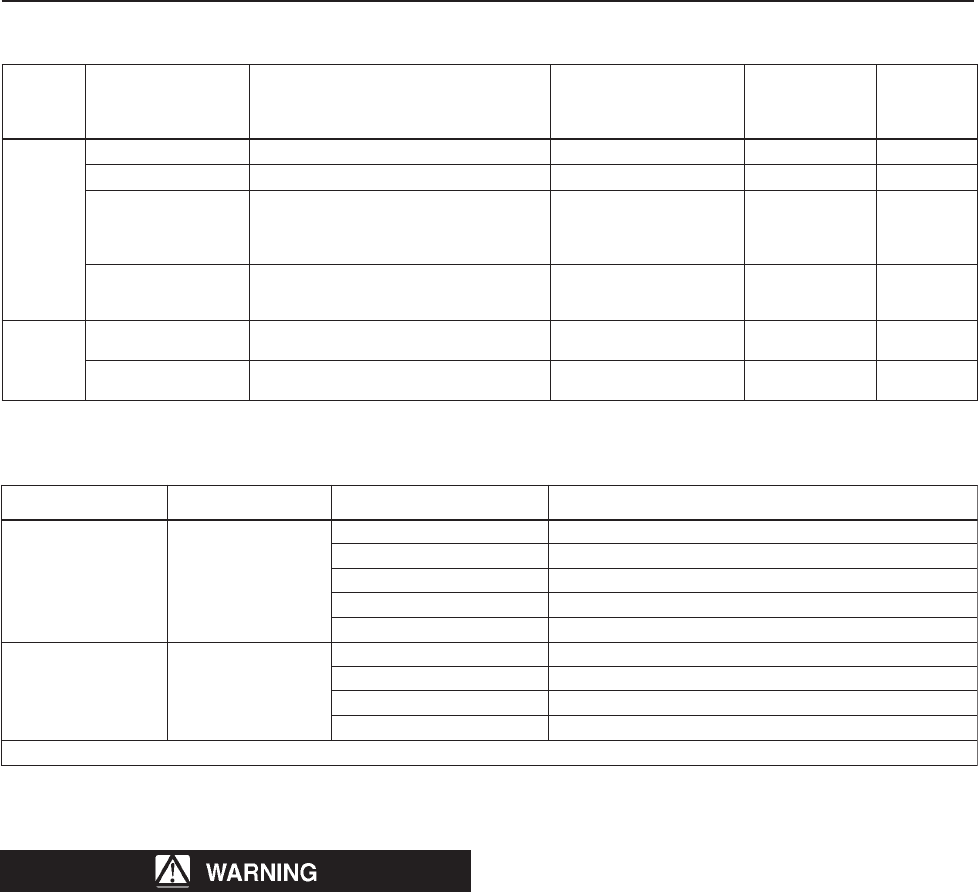
SEGNARTNIOPTESEPYTTUHS-MALS GNIRPSEVLAVNIAMHTIWESU
REBMUN
)1(
MUMIXAMOTMUMINIM
ERUSSERPPIRT
ffotuhSerusserprevO
)OSPO( PL
2,1rabm36ot03).c.wsehcni-52ot21(
4,3,2,1rabm031ot05).c.wsehcni-25ot02(
6,5,4,3rabm072ot59)gisp9.3ot4.1(
9,8,7,6,5rabm006ot062)gisp7.8ot8.3(
9rabm0011ot004)gisp61ot8.5(
ffotuhSerusserprednU
)OSPU( PL
3,2rabm03ot6).c.wsehcni-21ot2(
6,5,4,3rabm57ot01).c.wsehcni-03ot4(
8,7,6,5rabm061ot52)gisp3.2ot63.0(
9,8,7rabm057ot001)gisp8.01ot5.1(
.rebmungnirpsevlavniamrof3elbateeS.1
Table 6. Type VSX-2 High and Low Trip Pressure Ranges
EPYT
REBMUN
GNIRPSLORTNOC
ROLOC
3ELBATEES(
)EGNARROF
EGNARERUSSERPTELTUO
MAERTSNWODMUMIXAM
HTIWERUSSERP
NIROTINOMLARGETNI
,NOITAREPOrab)GISP(
FEILER
ROTINOM
ROLOCGNIRPS
FOREBMUN
GNIRPS
STAES
DERIUQER
,302S
P302S
nworBrabm21ot0).c.wsehcni-5ot0(55)gisp8.0(neerG0
kcalB/deRrabm42ot01).c.wsehcni-5.9ot4(neerG1
yarG
rabm53ot02
rabm03ot02
rabm05ot52
rabm25ot72
).c.wsehcni-41ot8(
).c.wsehcni-21ot8(
).c.wsehcni-02ot01(
).c.wsehcni-12ot11(
--
69
421
251
--
)4.1(
)8.1(
)2.2(
neerG
deR
deR
eulB
2
0
1
0
neergkraD
rabm07ot53
rabm28ot54
rabm07ot53
).c.wsehcni-82ot41(
).c.wsehcni-33ot81(
)gisp0.1ot5.0(
391
702
702
)8.2(
)0.3(
)0.3(
deR
eulB
revliS
2
1
0
,H302S
P302S
eulbkraD rabm011ot07
rabm011ot25
)gisp6.1ot0.1(
)gisp6.1ot57.0(
262
672
)8.3(
)0.4(
eulB
revliS
2
1
egnarO rabm551ot68
rabm422ot68
)gisp52.2ot52.1(
)gisp52.3ot52.1(
543
314
)0.5(
)0.6(
revliS
revliS
2
3
Table 5. Integral Monitor Data
S200 Series
4
Overpressure Protection
The recommended pressure limitations are stamped on
the regulator nameplate. Some type of overpressure
protection is needed if the actual inlet pressure exceeds the
maximum operating outlet pressure rating. Overpressure
protection should also be provided if the regulator inlet
pressure is greater than the safe working pressure of the
downstream equipment.
Regulator operation below the maximum pressure limitations
does not preclude the possibility of damage from external
sources or debris in the line. The regulator should be inspected
for damage after any overpressure condition.
Startup
The regulator is factory set at approximately the midpoint of
the spring range or the pressure requested, so an initial
adjustment may be required to give the desired results. With
proper installation completed and relief valves properly
adjusted, slowly open the upstream and downstream shutoff
valves.
Type VSX-2 Startup
The Type VSX-2 is shipped in the tripped position and will
need to be reset. If the Type VSX-2 is a high trip only, it can be
reset before starting the regulator. If the Type VSX-2 is a high
and low trip, the regulator will have to be started and the
downstream system pressurized before the Type VSX-2 can
be reset.
Adjustment
To change the outlet pressure, remove the closing cap or
loosen the locknut and turn the adjusting screw clockwise
to increase outlet pressure or counterclockwise to decrease
pressure. Monitor the outlet pressure with a test gauge
during the adjustment. Replace the closing cap or tighten
the locknut to maintain the desired setting.
Type VSX-2 Trip Adjustment
Note
An adjustment tool is included with the Type VSX-2.
Use only this tool to make adjustments to the unit.
To make adjustments, the overpressure trip spring
is found under the outer adjusting screw and the
underpressure trip spring is found under the inner
adjusting screw.
To adjust the Overpressure Trip Spring:
1. Adjust the overpressure trip setting to its maximum
compression.
2. If present, adjust the underpressure spring to its
minimum compression.
3. Backpressure the unit with the desired trip pressure.
4. Reduce the overpressure trip spring compression until
the Type VSX-2 trips.
To adjust the Underpressure Trip Spring:
1. Adjust the underpressure trip spring back to its minimum
compression.
2. Backpressure the unit with the desired trip pressure.
3. Increase the underpressure trip spring compression until
the Type VSX-2 trips.
Taking Out of Service (Shutdown)
To avoid personal injury resulting from sudden
release of pressure, isolate the regulator from all
pressure before attempting disassembly.
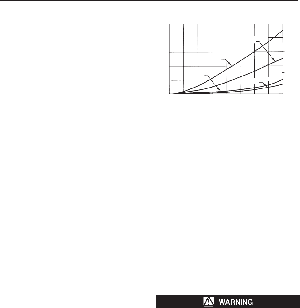
Figure 1. Minimum Inlet Pressure Required to Prevent Shutoff
on all Sizes of S204, S204H, S206, and S206H Regulators at
Indicated Flow
FLOW RATE, SCFH OF 0.6 SPECIFIC GRAVITY NATURAL GAS
FLOW RATE, m3/h(n) OF 0.6 SPECIFIC GRAVITY NATURAL GAS
50
40
30
20
10
0
3.0
2.0
1.0
0
0 1000 2000 3000 4000 5000 6000 7000 8000
MINIMUM INLET PRESSURE, PSIG
MINIMUM INLET PRESSURE, bar
0 26.8 53.6 80.4 107 134 160 188 214
1-INCH (25,4 mm)
SEAT RING
1/2-INCH (12,7 mm)
SEAT RING
5/8-INCH (15,9 mm)
SEAT RING
1-3/16-INCH (30,2 mm)
SEAT RING
S200 Series
5
50A9455
50A9457
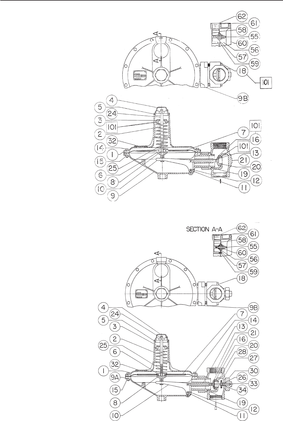
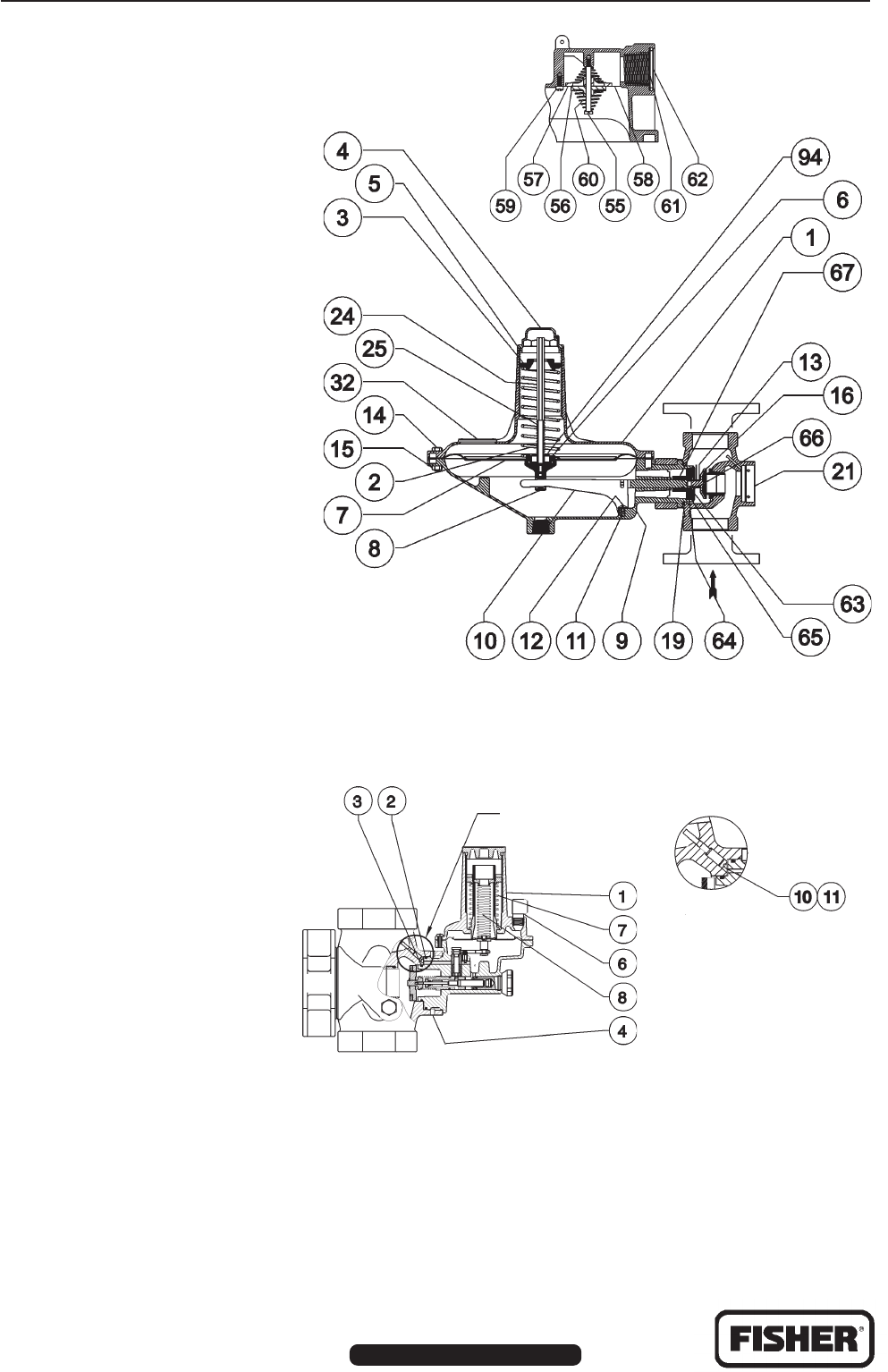
Type S201 and S202 Parts List
Key Description
1 Spring Case
2 Spring
3 Adjusting Screw
4 Closing Cap
5 Closing Cap Gasket
6 Upper/Lower Spring Seat
7A Diaphragm
7B Diaphragm Head
8 Pusher Post
9 Lower Casing Assembly
10 Lever
11 Pin
12 Machine Screw
13 Valve Stem Assembly
14 Cap Screw
15 Hex Nut
16 Disk Holder Assembly
17 Diaphragm Plate
18 Cap Screw
19 O-Ring
20 Seat Ring
21 Body
24 Cap Screw
25 Relief Valve Spring
32 Nameplate
46 Pipe Plug
53 Hex Nut
55 Flapper Stem
56 Lower Flapper
57 Upper Flapper
58 Seat Ring
59 Self-Tapping Screw
60 Spring
61 Screen
62 Snap Ring
Figure 2. Type S202 Assembly
Figure 3. Type S206 Assembly
Type S204 and S206 Parts List
Key Description
1 Spring Case
2 Spring
3 Adjusting Screw
4 Closing Cap
5 Closing Cap Gasket
6 Lower Spring Seat
7 Diaphragm & Head Assembly
7A Diaphragm
8 Pusher Post (S204)
8 Ball Stem Assembly (S206)
9 Lower Casing Assembly
10 Lever
11 Pin
12 Machine Screw
13 Valve Stem Assembly
14 Cap Screw
15 Hex Nut
16 Disk Holder Assembly
18 Cap Screw
19 O-Ring
20 Seat Ring
21 Body
24 Reset Stem
25 Relief Valve Spring (S206)
26 Back Disk Spring
27 Back Disk Holder
28 Disk Spacer
32 Nameplate
33 Valve Stem
34 Gasket
55 Flapper Stem
56 Lower Flapper
57 Upper Flapper
58 Seat Ring
59 Self-Tapping Screw
60 Spring
61 Screen
62 Snap Ring
S200 Series
For information, contact Fisher Controls, International:
Within USA (800) 588-5853 – Outside USA (972) 542-0132
Italy – (39) 051-4190-606
Singapore – (65) 770-8320
Mexico – (52) 57-28-0888
©Fisher Controls International, Inc., 2002; All Rights Reserved
Fisher and Fisher Regulators are marks owned by Fisher Controls International, Inc. The Emerson logo is a trade mark and service mark of Emerson Electric Co.
All other marks are the property of their respective owners.
The contents of this publication are presented for informational purposes only, and while every effort has been made to ensure their accuracy, they are not to be construed as warranties or guarantees, express
or implied, regarding the products or services described herein or their use or applicability. We reserve the right to modify or improve the designs or specifications of such products at any time without notice.
Printed in U.S.A. www.FISHERregulators.com
T80390-A2
B2517-2
T80388-C
B2508-2
T80388-C
B2495-2
Figure 4. Type S209 Assembly
Type S208 and S209 Parts List
Key Description
1 Spring Case
2 Spring
3 Adjusting Screw
4 Closing Cap
5 Closing Cap Gasket
6 Lower Spring Seat
7 Diaphragm and Diaphragm Head
8 Pusher Post
9 Lower Casing Assembly
10 Lever
11 Pin
12 Machine Screw
13 Valve Stem Assembly
14 Cap Screw
15 Hex Nut
16 Disk Holder
17 Diaphragm Head
19 O-Ring
20 Orifice
21 Body
24 Stem
25 Relief Valve Spring
32 Nameplate
55 Flapper Stem
56 Lower Flapper
57 Upper Flapper
58 Orifice
59 Self-Tapping Screw
60 Spring
61 Screen
62 Snap Ring
63 Retaining Ring
64 O-Ring
65 O-Ring
67 Stem Adaptor
94 Relief Restriction
121 Insert
122 O-Ring
123 Pipe Plug
Figure 5. Type VSX-2 Assembly
Type VSX-2 Parts List
Key Description
1 VSX-2 Module
2 Upper O-Ring
3 Lower O-Ring
4 Set Screw
6 Vent Assembly
7 High-Pressure Control Spring
8 Low-Pressure Control Spring
10 Machine Screw
11 Gasket
13 Pipe Plug
VIEW A
VIEW A
