User manual

EPOC Flex
User Manual
Last updated: June 12, 2018
Copyright EMOTIV, Inc.
EMOTIV EPOC Flex Manual 1 of 15

Table of Contents
EPOC Flex 1
User Manual 1
Table of Contents 2
Introduction 3
Safety Precautions 3
Technical Specifications 4
Compliance Accreditation 5
Controller Assembly› 6
Charging and LED Indicators 7
Electrode Assemblies 8
Example Electrode placement 8
EPOC Flex Cap 10
Specifying Cap Size 11
Package ContentsAssembly - Quick Start 13
Assembly Quick Start 15
Cleaning and Maintenance 16
EMOTIV EPOC Flex Manual 2 of 15

Introduction
This document is intended to help you get started using the EPOC Flex. The EPOC Flex is a
32-channel, flexible EEG system. It was built on the award winning EPOC+ technology and is
designed for researchers who would like to have a more flexible sensor placement and / or
greater density of sensors. The reference sensors can be placed in any location on the ear with
included earclips. EmotivPRO v1.4+ is required for operation.
If you have any queries beyond the scope of this document, please contact us through our
online support.
Safety Precautions
● EPOC Flex is a consumer product, it is not intended to use be used for in-patient health
care or in hazardous environments.
● EPOC Flex is designed to be used at room temperature; rapid changes in temperature
will affect the performance of the amplifiers and increase the noise floor.
● EPOC Flex can be used with gel or saline based sensors.
● WARNING: EPOC+ is powered by a Lithium-Polymer battery that is rated for operation
in <45C environments. It is not user replaceable, please contact support if you suspect a
fault or have any questions.
● WARNING: Do not open the enclosure. Doing so will void the warranty and can damage
the headset.
● WARNING: Do not charge EPOC Flex while wearing the device. In the unlikely event
your PC has a faulty power supply you and your headset could unintentionally become
the ground path and so If EPOC Flex detects a USB connection when turned on it will
stop communicating.
EMOTIV EPOC Flex Manual 3 of 15

Technical Specifications
No. of Channels
32 (plus CMS/DRL references)
Channel names (International 10-20 locations)
Configurable on standard 72 channel 10-20 map.
Sampling method
Sequential sampling. Single ADC
Sampling rate
128 SPS (1024 Hz internal)
EEG Resolution
14 bits 1 LSB = 0.51μV (16 bit ADC, 2 bits instrumental
noise floor discarded)
Max Slew Rate
32.64uV/sample (Compression required for BLE data
transmission)
Bandwidth
0.2 - 45Hz, digital notch filters at 50Hz and 60Hz
Filtering
Built in digital 5th order Sinc filter
Dynamic range (input referred)
+/- 4.12 uV
Coupling mode
AC coupled
Connectivity
Proprietary 2.4GHz wireless, BLE(coming soon)
Battery Capacity.
LiPo battery 680mAh
Battery life (typical)
9 hours
Impedance Measurement
Real-time contact quality using patented system
IMU Part
ICM-20948 (support coming soon)
Accelerometer
3-axis +/-8g
Gyroscope
3-axis +/- 2000 dps
Magnetometer
3-axis +/- 12 gauss
MEMS Sampling
16 Hz
MEMS Resolution
16-bit
Sensor Material
Sintered Ag/AgCl can be used with gel
EMOTIV EPOC Flex Manual 4 of 15

Compliance Accreditation
FCC ID Number 2ADIH-FLEX01 and IC ID Number: 12769A-FLEX01.
EMOTIV has undertaken testing and confirms:
This device complies with the radio equipment directive (2014/53/EU).
This device complies with part 15 of the FCC Rules. Operation is subject to the following two
conditions: (1) This device may not cause harmful interference, and (2) this device must accept
any interference received, including interference that may cause undesired operation.
This equipment has been tested and found to comply with the limits for a Class B digital device,
pursuant to part 15 of the FCC Rules. These limits are designed to provide reasonable
protection against harmful interference in a residential installation. This equipment generates,
uses and can radiate radio frequency energy and, if not installed and used in accordance with
the instructions, may cause harmful interference to radio communications. However, there is no
guarantee that interference will not occur in a particular installation. If this equipment does
cause harmful interference to radio or television reception, which can be determined by turning
the equipment off and on, the user is encouraged to try to correct the interference by one or
more of the following measures:
- Reorient or relocate the receiving antenna.
- Increase the separation between the equipment and receiver.
- Connect the equipment into an outlet on a circuit different from that to which the receiver is
connected.
- Consult the dealer or experienced person for help.
This Class B digital apparatus complies with Canadian ICES-003.
Cet appareil numérique de la classe B est conforme à la norme NMB-003 du Canada.
This device contains licence-exempt transmitter(s)/receiver(s) that comply with Innovation,
Science and Economic Development Canada’s licence-exempt RSS(s). Operation is subject to
the following two conditions:
1. This device may not cause interference.
2. This device must accept any interference, including interference that may cause
undesired operation of the device.
Please Note: Changes or modifications not expressly approved by the party responsible
for compliance could void the user's authority to operate the equipment.
EMOTIV EPOC Flex Manual 5 of 15

EMOTIV EPOC Flex Manual 6 of 15

Controller Assembly›
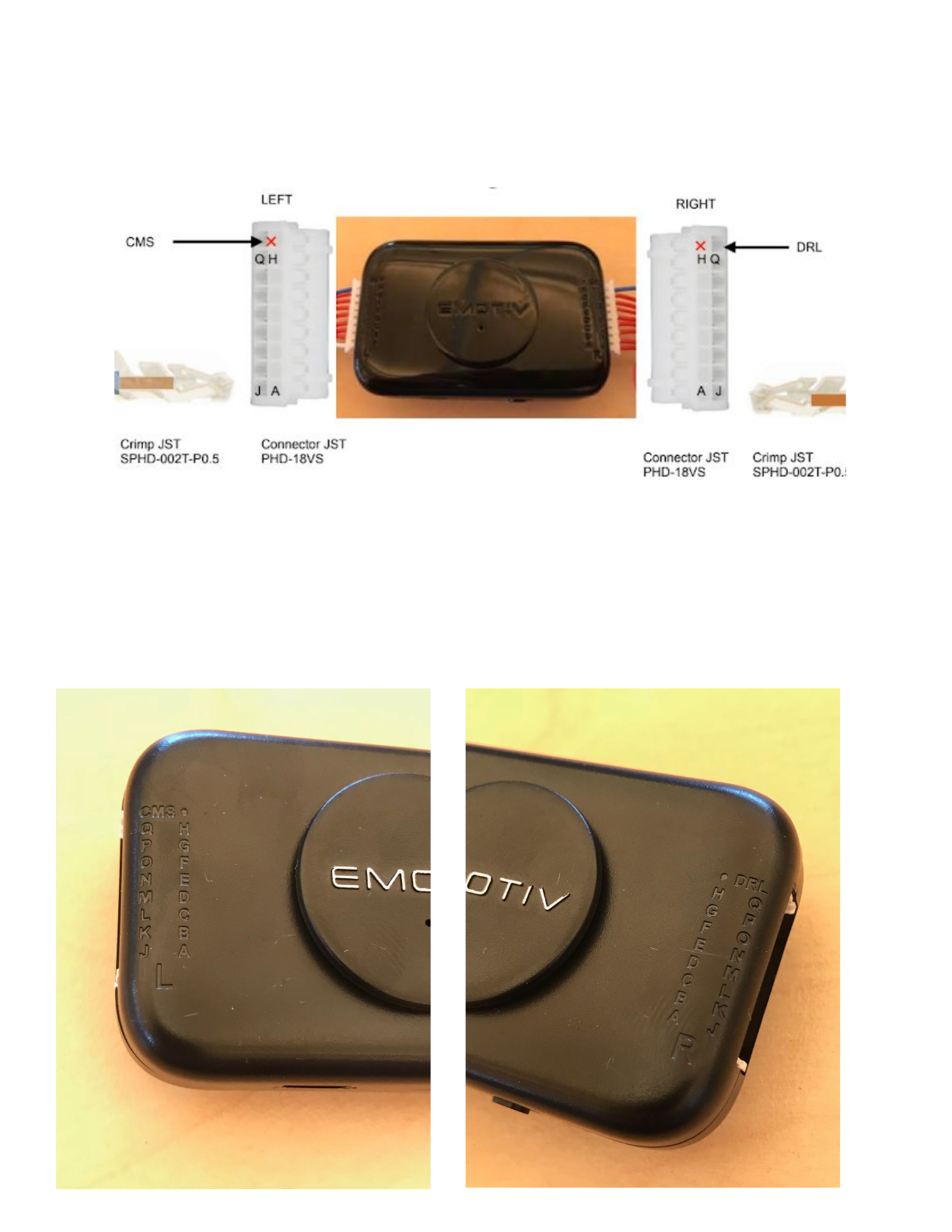
The EPOC Flex controller pictured above has 16 channels connected on the left + CMS input
and 16 channels on the right + DRL output. These channels are connected in two rows A-H and
J-Q, In software L or R is added in front to make it LA, LB, etc and RA, RB, etc. These labels
allow users to easily trace signal problems from the name shown on software to the sensor. The
connectors shown are JST PHD-18VS which are easily sourced from digikey if replacements
are required.
EMOTIV EPOC Flex Manual 7 of 15

Charging and LED Indicators
The EPOC Flex has a single RGB LED to indicate power on and charging as shown in the table
below.
Action
LED Colour
Power OFF / Battery Flat
OFF
Powered On
BLUE
USB connected / Charging
ORANGE
Charge complete
GREEN
Firmware failure
Fade On - Fade Off Blue
USB connected / powered On
WHITE
It is recommended that your headset is fully charged prior to taking recordings. The charge time
depends on the remaining capacity in the Lithium Polymer cell and can take up to four hours. If
the EPOC Flex LED does not turn blue on power on it requires charging. Please use the
provided USB Micro-B cable to recharge using any usb port.
Note 1: The headset will charge faster if connected to a dedicated USB port.
Note 2: If the headset it heavily depleted or hasn’t been used for a few months, leave it
connected for 24hrs.
EMOTIV EPOC Flex Manual 8 of 15

Electrode Assemblies
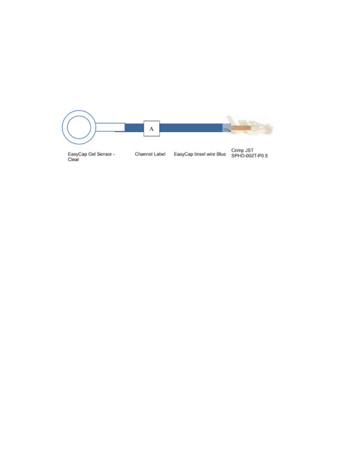
Emotiv has developed the EPOC Flex to use EasyCap Multi-rode gel sensors that are
pre-configured and easy to setup. The electrodes are attached to 150mm of tinsel wire and
terminated with JST gold plated crimps. This length is designed to be long enough to reach any
position on the cap.
Electrodes are colour coded, blue for left, red for right and black for references. In addition each
sensor will be individually labelled with the channel name connected. The aim of this colour
coding is simple, when troubleshooting you can quickly identify the colour and channel name in
the software and quickly find the electrode on the cap.
There will be excess wire once the cap is fitted, we recommend that you place a cap over the
top to stop these wires catching. If your research involves minimising motion artifacts keeping
the excess wire secured will be required, either by tidying down the wire or feeding through
adjacent empty holes. If a cap with electrode leads cut to length is required please contact us.
We know that researchers can have different needs for references, so we have included
earclips and adhesive pads that fit the electrodes.
Example Electrode placement
Below is an example image showing the electrode placement as per the initial setup in
EmotivPRO. This placement gives good coverage of the entire head, with the pod fitted in the
back pocket.
EMOTIV EPOC Flex Manual 9 of 15

EMOTIV EPOC Flex Manual 10 of 15

EPOC Flex Cap
The standard EPOC Flex cap follows the official 10-20 system and has 72 openings as shown
above. The controller has two pockets it can be placed in on the cap, one is fitted about Cz and
the other Iz.
The caps can be ordered in our standard sizes are 54, 56 and 58 cm in a black high comfort
material in a caucasian cut. Other sizes, hole positions, materials and cuts are available please
contact online support for further information.
EMOTIV EPOC Flex Manual 11 of 15

Specifying Cap Size
Specifying the right cap size is critical for keeping for ensuring the sensors are in the right place
when taking measurements. Our supplier recommends measuring the head diameter in the
horizontal circumference as shown in the image below.
Once you have the measurement for your test subjects you specify the closest size to the ones
available for example 54.5cm → 54cm, 59cm → 58cm, etc. If you need larger or smaller sizes
please contact support.
EMOTIV EPOC Flex Manual 12 of 15

Package Contents
When you receive your order you will find a package that looks like this:
<White Box >
With this shipping box will be the EPOC Flex Package
<Image>
Please note if you order more than one cap or electrode set these will be in the shipping box.
EPOC Flex is designed to allow users to buy the components required to meet their research
need. When you open the box you will find the following:
1. Controller
2. Universal USB Receiver (included with
Controller)
3. EasyCap Emotiv Custom Cap
4. Electrode Sensors
EMOTIV EPOC Flex Manual 13 of 15

<IMAGE>
5. Micro-B to A USB cable
Earclips + adhesive pads
EMOTIV EPOC Flex Manual 14 of 15

Assembly Quick Start
We recommend that you use a polystyrene head when setting up the cap as this will make
setup easier.
1. Remove the cap, electrode trees and controller from the packaging.
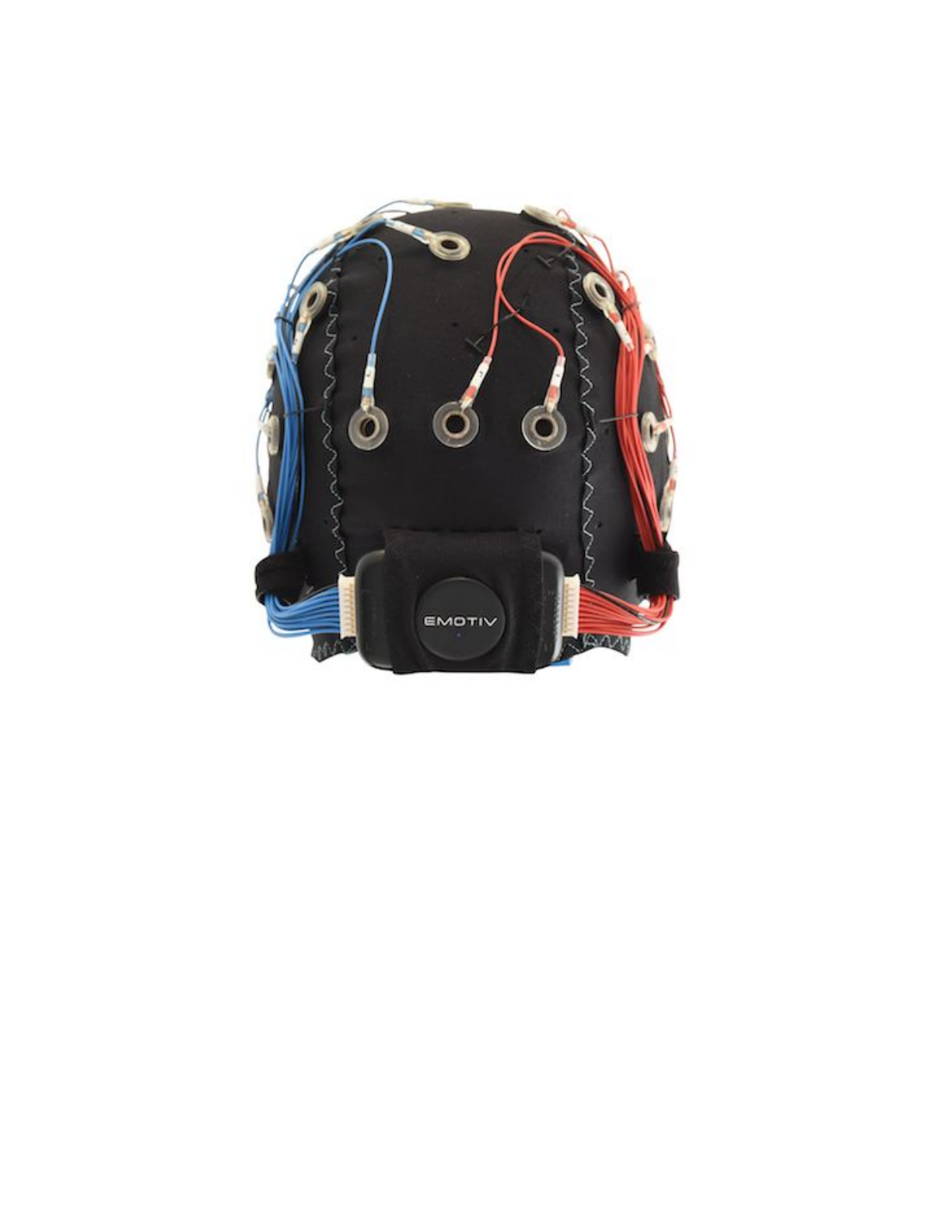
2. Fit the controller to the cap with the emotiv logo as pictured above.
3. Fit the blue wire tree into the left side of the controller and the red wire tree into the right
side.
4. Starting with LA position your sensors into the cap, we recommend that you try to keep
left and right as a mirror image to make setup simple. See our example layout above.
5. The cap is now ready for fitting onto the test subject.
6. Please plug in the universal USB receiver into your computer and ensure the power
switch is to the right a blue LED will turn on indicating power on. You should also see the
lights on the receiver change to indicate it is receiving data.
Cleaning and Maintenance
EMOTIV EPOC Flex Manual 15 of 15