EnGenius Technologies EDS1130 Intelligent IP-Camera User Manual 1 of 2
EnGenius Technologies Intelligent IP-Camera Users Manual 1 of 2
UserManual.wiki
>
EnGenius Technologies
>
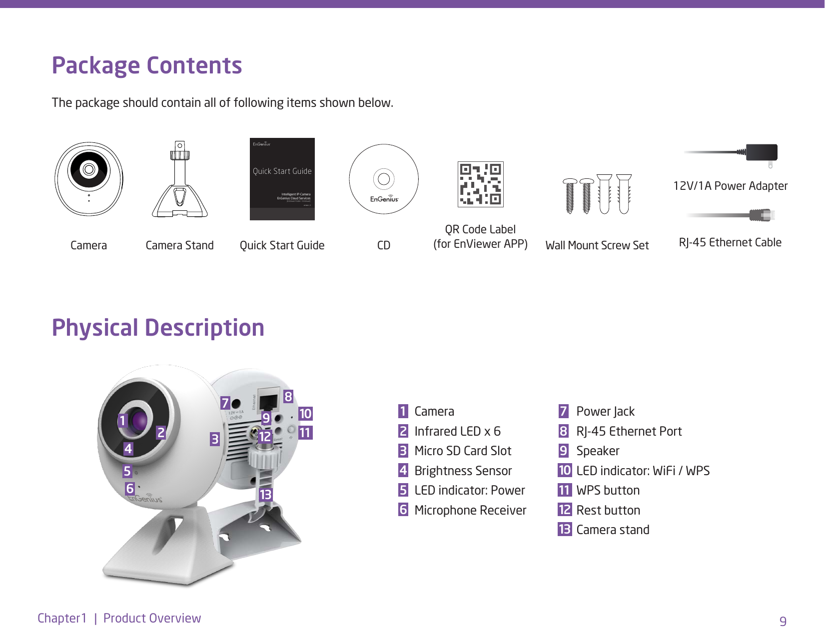
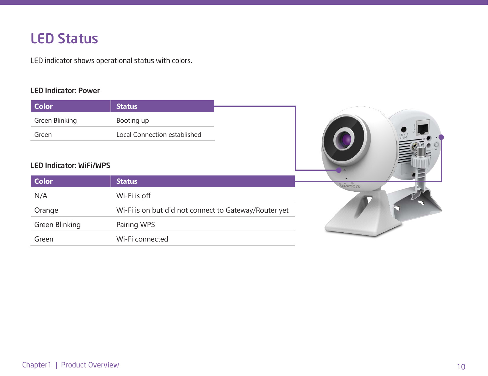
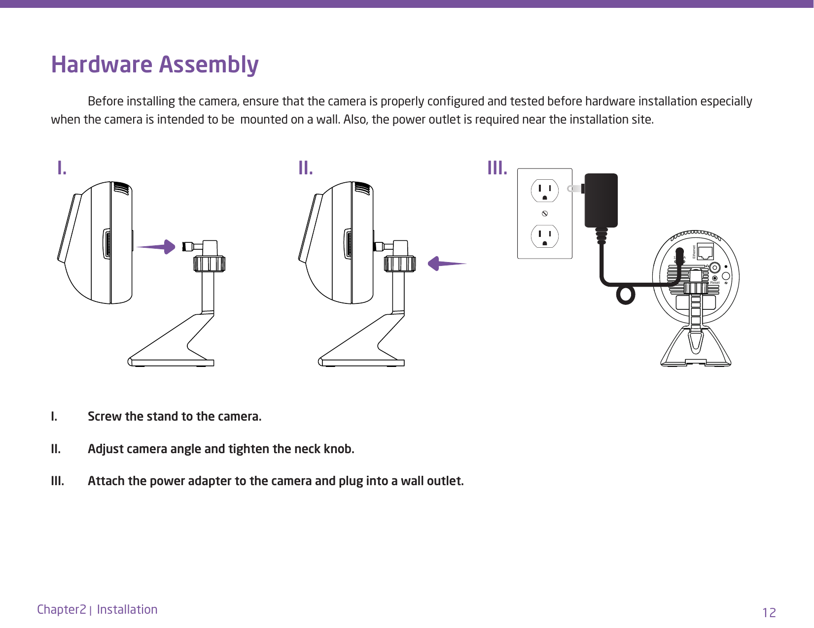
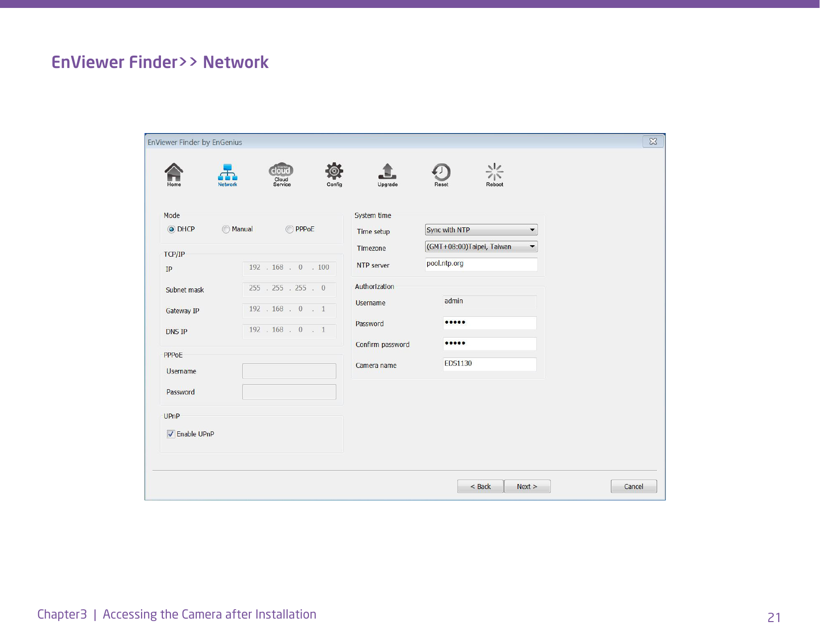
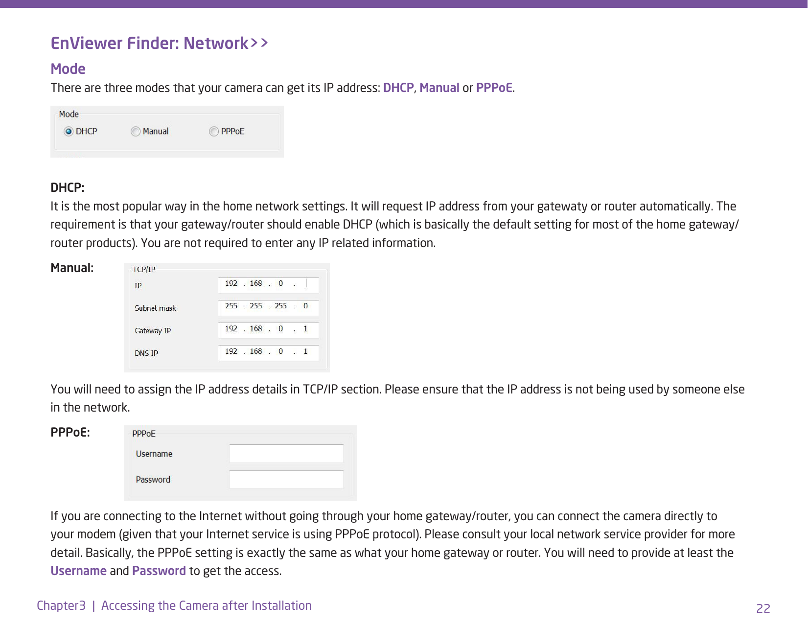
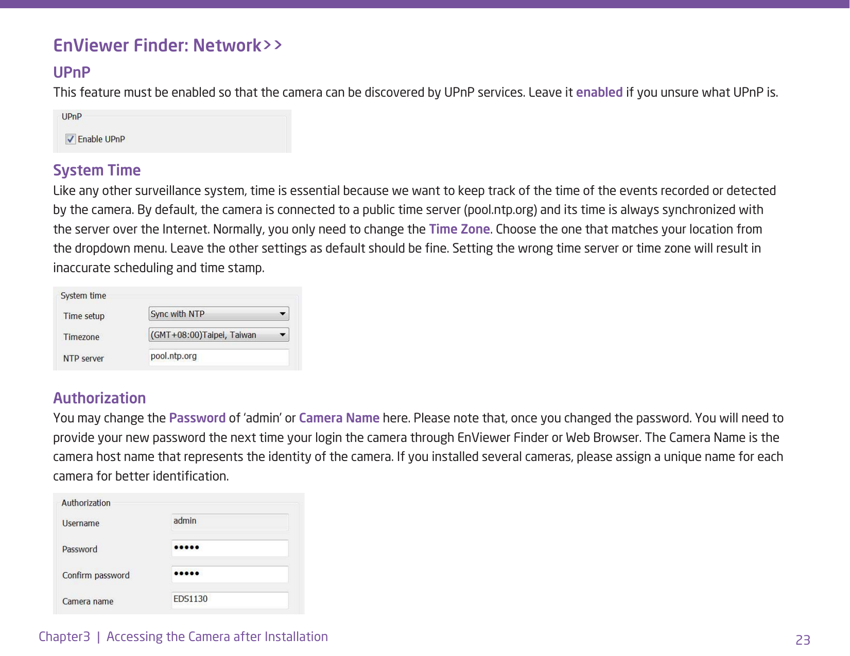
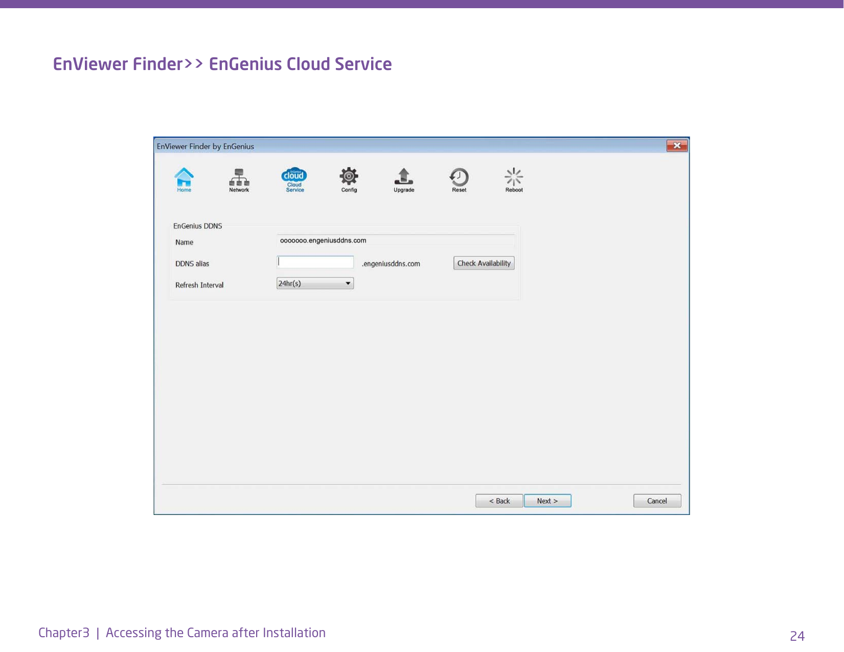
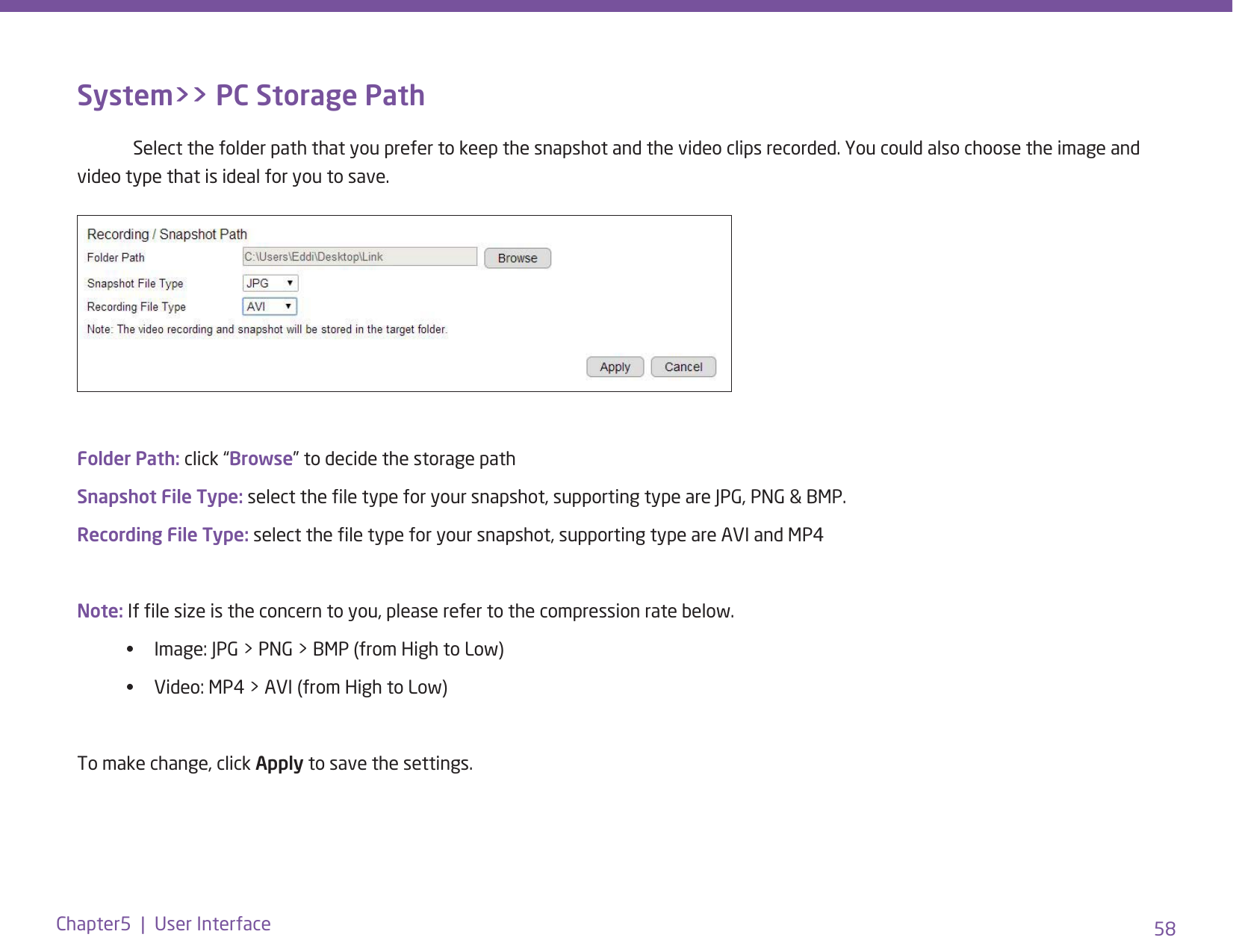
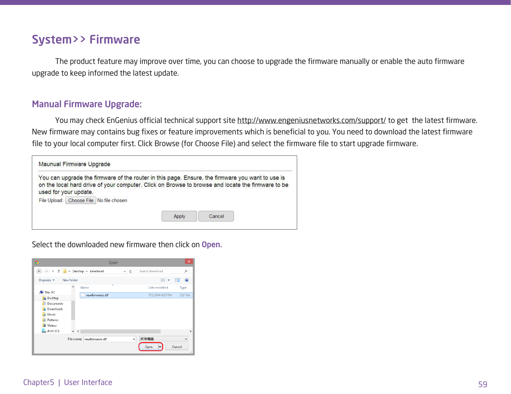
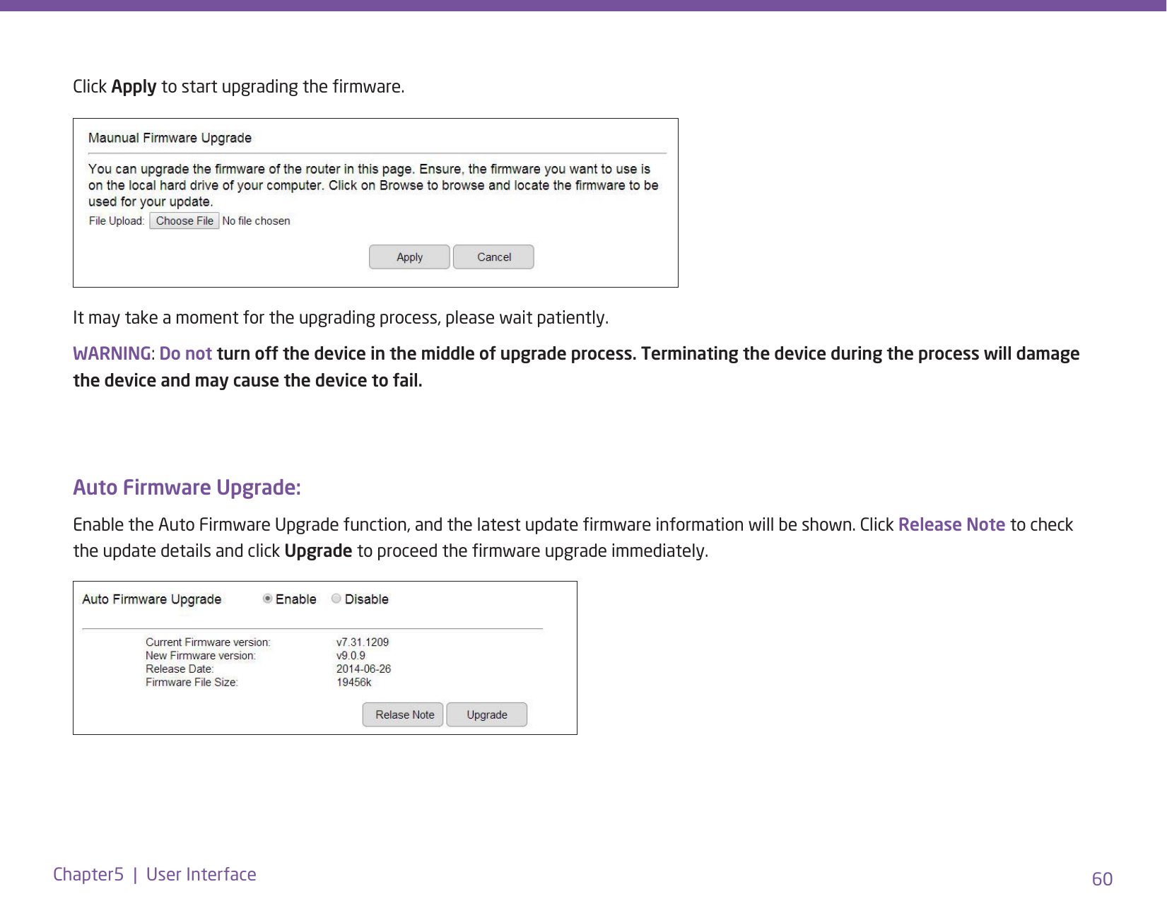
EDS1130 User Manual
>
Users Manual (1 of 2).pdf
Contents
1.
Users Manual (1 of 2).pdf
2.
Users Manual (2 of 2).pdf
Users Manual (1 of 2).pdf
Navigation menu
Upload a User Manual
Namespaces
Wiki Guide
HTML
PDF
Info
Views
User Manual
Discussion / Help
Navigation