EnGenius Technologies ENS500 LONG RANGE WIRELESS 11N OUTDOOR AP/CB User Manual ENS500EXT
EnGenius Technologies LONG RANGE WIRELESS 11N OUTDOOR AP/CB ENS500EXT
Contents
- 1. User Manual Part 1
- 2. User Manual Part 2
- 3. Users Manual_rev 2.pdf
User Manual Part 1

WIRELESS 11N LONG RANGE OUTDOOR AP / CB
ENS500EXT User Guide
V1.0
TABLE OF CONTENTS
I
TABLE OF CONTENTS
Product Overview
Package Contents 1-1
Product Overview 1-2
Hardware Features . . . . . . . . . . . . . . . . . . . . . . . . . . . . . . . . . . . . . . . . . . . . . . . . . . .1-2
Software Features . . . . . . . . . . . . . . . . . . . . . . . . . . . . . . . . . . . . . . . . . . . . . . . . . . . .1-2
Benefits . . . . . . . . . . . . . . . . . . . . . . . . . . . . . . . . . . . . . . . . . . . . . . . . . . . . . . . . . . .1-3
Technical Specification. . . . . . . . . . . . . . . . . . . . . . . . . . . . . . . . . . . . . . . . . . . . . . . . .1-4
Hardware Specification . . . . . . . . . . . . . . . . . . . . . . . . . . . . . . . . . . . . . . . . . . . . . . .1-4
Software Specification. . . . . . . . . . . . . . . . . . . . . . . . . . . . . . . . . . . . . . . . . . . . . . . .1-4
Environment & Mechanical. . . . . . . . . . . . . . . . . . . . . . . . . . . . . . . . . . . . . . . . . . . . .1-4
Wireless Specification . . . . . . . . . . . . . . . . . . . . . . . . . . . . . . . . . . . . . . . . . . . . . . . .1-5
Product Layout 1-6
TABLE OF CONTENTS
II
Installation
System Requirements 2-1
Installing the Device 2-2
Pre-Installation Guidelines . . . . . . . . . . . . . . . . . . . . . . . . . . . . . . . . . . . . . . . . . . . . . .2-2
Installing the Device . . . . . . . . . . . . . . . . . . . . . . . . . . . . . . . . . . . . . . . . . . . . . . . . . .2-2
Web Configuration
Logging In 3-1
Best Practices . . . . . . . . . . . . . . . . . . . . . . . . . . . . . . . . . . . . . . . . . . . . . . . . . . . . . . .3-2
Basic Network Settings
System Status 4-1
Using Save/Reload 4-1
Viewing System Information 4-2
Viewing Wireless Client List 4-4
Viewing System Log 4-5
Viewing Connection Status 4-6
Viewing DHCP Client Table 4-7
Viewing WDS Link List 4-8
TABLE OF CONTENTS
III
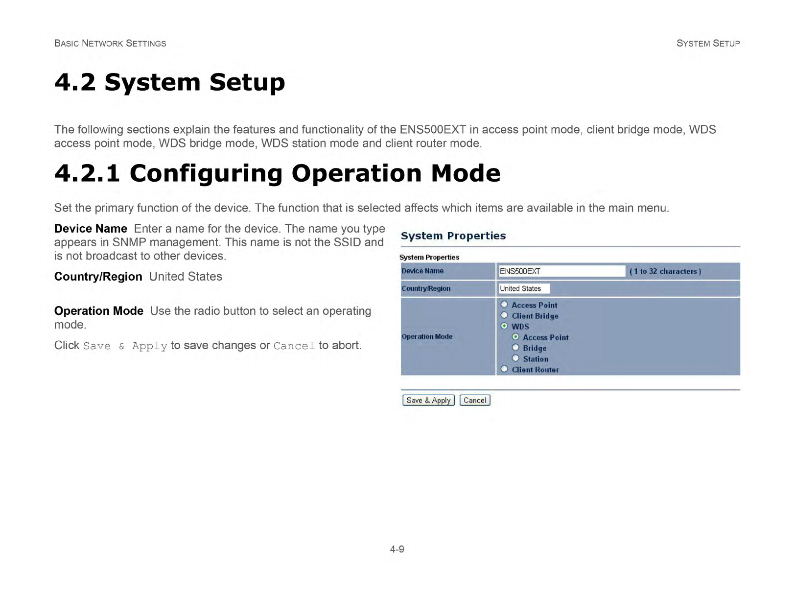
System Setup 4-9
Configuring Operation Mode 4-9
Configuring IP Settings 4-10
Configuring Spanning Tree Settings 4-11
Router Setup 4-12
Configuring WAN Settings 4-12
Static IP. . . . . . . . . . . . . . . . . . . . . . . . . . . . . . . . . . . . . . . . . . . . . . . . . . . . . . . . . .4-12
Dynamic IP. . . . . . . . . . . . . . . . . . . . . . . . . . . . . . . . . . . . . . . . . . . . . . . . . . . . . . . .4-13
Point-to-Point Protocol over Ethernet (PPPoE). . . . . . . . . . . . . . . . . . . . . . . . . . . . . . . .4-14
Point-to-Point Tunnelling Protocol (PPTP) . . . . . . . . . . . . . . . . . . . . . . . . . . . . . . . . . . .4-15
Configuring LAN Settings 4-17
Configuring VPN Pass-Through 4-18
Configuring Port Forwarding 4-19
Configuring Demilitarized Zone 4-21
Configuring Wireless LAN 4-22
Configuring Wireless Settings 4-22
Access Point Mode. . . . . . . . . . . . . . . . . . . . . . . . . . . . . . . . . . . . . . . . . . . . . . . . . . .4-22
Client Bridge Mode . . . . . . . . . . . . . . . . . . . . . . . . . . . . . . . . . . . . . . . . . . . . . . . . . .4-24
WDS Bridge Mode . . . . . . . . . . . . . . . . . . . . . . . . . . . . . . . . . . . . . . . . . . . . . . . . . . .4-25
Client Router Mode . . . . . . . . . . . . . . . . . . . . . . . . . . . . . . . . . . . . . . . . . . . . . . . . . .4-27
TABLE OF CONTENTS
IV
Configuring Wireless Security 4-28
Wired Equivalent Privacy (WEP) . . . . . . . . . . . . . . . . . . . . . . . . . . . . . . . . . . . . . . . . .4-28
Wi-Fi Protected Access Pre-Shared Key (WPA-PSK) . . . . . . . . . . . . . . . . . . . . . . . . . . . .4-29
Wi-Fi Protected Access 2 Pre-Shared Key (WPA2-PSK). . . . . . . . . . . . . . . . . . . . . . . . . .4-30
Wi-Fi Protected Access Pre-Shared Key (WPA-PSK) Mixed . . . . . . . . . . . . . . . . . . . . . . .4-31
Wi-Fi Protected Access (WPA). . . . . . . . . . . . . . . . . . . . . . . . . . . . . . . . . . . . . . . . . . .4-32
Wi-Fi Protected Access 2 (WPA2) . . . . . . . . . . . . . . . . . . . . . . . . . . . . . . . . . . . . . . . .4-33
Wi-Fi Protected Access (WPA) Mixed . . . . . . . . . . . . . . . . . . . . . . . . . . . . . . . . . . . . . .4-34
Configuring Wireless MAC Filter 4-35
Configuring WDS Link Settings 4-36
Configuring Wireless Advanced Settings 4-37
Management Setup 4-39
Configuring Administrator Account 4-39
Configuring Management VLAN 4-40
Configuring SNMP 4-41
Configuring Backup/Restore Settings 4-43
Configuring Firmware Upgrade 4-44
Configuring System Time 4-45
Configuring Wi-Fi Schedule 4-46
Add a Schedule Service . . . . . . . . . . . . . . . . . . . . . . . . . . . . . . . . . . . . . . . . . . . . . . .4-46
Schedule Services Table. . . . . . . . . . . . . . . . . . . . . . . . . . . . . . . . . . . . . . . . . . . . . . .4-47
TABLE OF CONTENTS
V
Configuring Command Line Interface 4-48
Configuring Logging 4-49
Configuring Diagnostics 4-50
Viewing Device Discovery 4-51
Configure Denial of Service Protection 4-52
Logging Out 4-53
Appendix A
Federal Communication Commission Interference Statement A-1
Appendix B
Industry Canada Statement B-1
Appendix C
WorldWide Technical Support C-1

CONVENTIONS
VI
Conventions
The following conventions are used to give the user additional
information about specific procedures or content. It is important
to pay attention to these conventions as they provide informa-
tion to prevent damage to equipment or personal injury.
General Conventions
The following general conventions are used in this document.
N/A:
Indicates that a component or a procedure is not applica-
ble to this model.
Prerequisite:
Indicates a requirement that must be addressed before
proceeding with the current function or procedure.
CAUTION!
CAUTIONS APPEAR BEFORE THE TEXT IT REFERENCES. CAU-
TIONS APPEAR IN CAPITAL LETTERS TO EMPHASIZE THAT THE
MESSAGE CONTAINS VITAL HEALTH AND SAFETY INFORMATION.
WARNING!
Warning information appears before the text it references
to emphasize that the content may prevent damage to the
device or equipment.
Important:
Indicates information that is important to know for the
proper completion of a procedure, choice of an option, or
completing a task.
Note:
Indicates additional information that is relevant to the cur-
rent process or procedure.
!
!
Example:
Indicates information used to demonstrate or explain an
associated concept.
CONVENTIONS
VII
Typographical Conventions
The following typographical conventions are used in this docu-
ment:
Italics
Indicates book titles, directory names, file names, path names,
and program/process names.
Constant width
Indicates computer output shown on a computer screen, includ-
ing menus, prompts, responses to input, and error messages.
Constant width bold
Indicates commands lines as entered on the computer. Vari-
ables contained within user input are shown in angle
brackets (< >).
Bold
Indicates keyboard keys that are pressed by the user.
COPYRIGHT
VIII
Copyright
This user guide and its content is copyright of © EnGenius Net-
works, 2012. All rights reserved.
Any redistribution or reproduction in part or in whole in any form
is prohibited.
Do not distribute, transmit, store in any form of electronic
retrieval system or commercially exploit the content without the
expressed written permission of EnGenius Networks.
Product Overview
Chapter 1
PRODUCT OVERVIEW PACKAGE CONTENTS
1-1
1.1 Package Contents
ENS500EXT
Quick Start Guide
Technical Support Card
Pole Mounting Strap x2
Wall Mounting Screw Set
PoE Injector (EPE1212) with Power Adapter
Two detachable 5 dBi high gain omni-directional antennas
Transmit high output power for
great coverage
PRODUCT OVERVIEW BENEFITS
1-3
Benefits
The ENS500EXT is the ideal product around which you can
build your WLAN. The following list summarizes a few key
advantages that WLANs have over wired networks:
Ideal for hard-to-wire environments
There are many scenarios where cables cannot be used to con-
nect networking devices. Historic and older buildings, open
areas, and busy streets, for example, make wired LAN installa-
tions difficult, expensive, or impossible.
Temporary workgroups
WLANs make it easy to provide connectivity to temporary work-
groups that will later be removed. Examples include parks, ath-
letic arenas, exhibition centers, disaster-recovery shelters,
temporary offices, and construction sites.
Ability to access real-time information
With a WLAN, workers who rely on access to real-time informa-
tion, such as doctors and nurses, point-of-sale employees,
mobile workers, and warehouse personnel, can access the data
they need and increase productivity, without having to look for a
place to plug into the network.
Frequently changed environments
WLANs are well suited for showrooms, meeting rooms, retail
stores, and manufacturing sites where workplaces are rear-
ranged frequently.
Wireless extensions to Ethernet networks
WLANs enable network managers in dynamic environments to
minimize overhead caused by moves, extensions to networks,
and other changes.
Wired LAN backup
Network managers can implement WLANs to provide backup
for mission-critical applications running on wired networks.
Mobility within training/educational
facilities
Training sites at corporations and students at universities are a
few examples where wireless connectivity can be used to facili-
tate access to information, information exchanges, and learn-
ing.
PRODUCT OVERVIEW TECHNICAL SPECIFICATION
1-4
Technical Specification
Hardware Specification
Physical Interface:
2 x RJ-45 for 10/100 Fast Ethernet; one port is compat-
ible with PoE
1 x Reset Button
Power Requirements:
Active Ethernet (Power over Ethernet)
Proprietary PoE design
Power Adapter 24V / 0.6A
Software Specification
Operation Mode: Client Bridge, Access Point, Client
Router, WDS AP, WDS Bridge, WDS Station
Wireless/Network:
Auto Channel Selection (Setting varies by Regular
Domains)
Obey Regulatory Power
Distance Control (802.1x ACK (acknowledgement)
timeout)
CLI Supported
802.1x Supplicant (CB Mode)
4 SSIDs
WDS AP / WDS Bridge / WDS Station
Multicast Supported
RADIUS Accounting
VLAN Tag / VLAN Pass-through
Auto Reboot
WiFi Scheduling
Security:
WEP Encryption-64/128/152 bit
WPA/WPA2 Personal (WPA-PSK using TKIP or AES)
WPA/WPA2 Enterprise (WPA-EAP using TKIP)
Hide SSID in beacons
MAC address filtering, up to 50 field
Wireless STA (Client) connected list
QoS: WMM
Environment & Mechanical
Temperature Range:
Operating -20°C~70°C
Storage -30°C to 80°C
Humidity (non-condensing): 0%~90% typical
Dimensions

PRODUCT OVERVIEW TECHNICAL SPECIFICATION
1-5
with antenna: 100mm (4”) x 37.5mm (1.375””) x
205mm (8”) (W x D x H)
without antenna: 100mm (4”) x 37.5mm (1.37”) x
189mm (7.375”) (W x D x H)
Weight
with antenna: 242g (0.11 lbs) ± 2g
without antenna: 275g (0.125lbs) ±2g
Wireless Specification
Frequency Band: 802.11a/n
Data rate: 300 Mbps
Antenna: 2 x Detachable SMA Connector
Note:
The maximum power of the radio frequency band may
be different depending on local regulations.
PRODUCT OVERVIEW PRODUCT LAYOUT
1-6
1.3 Product Layout
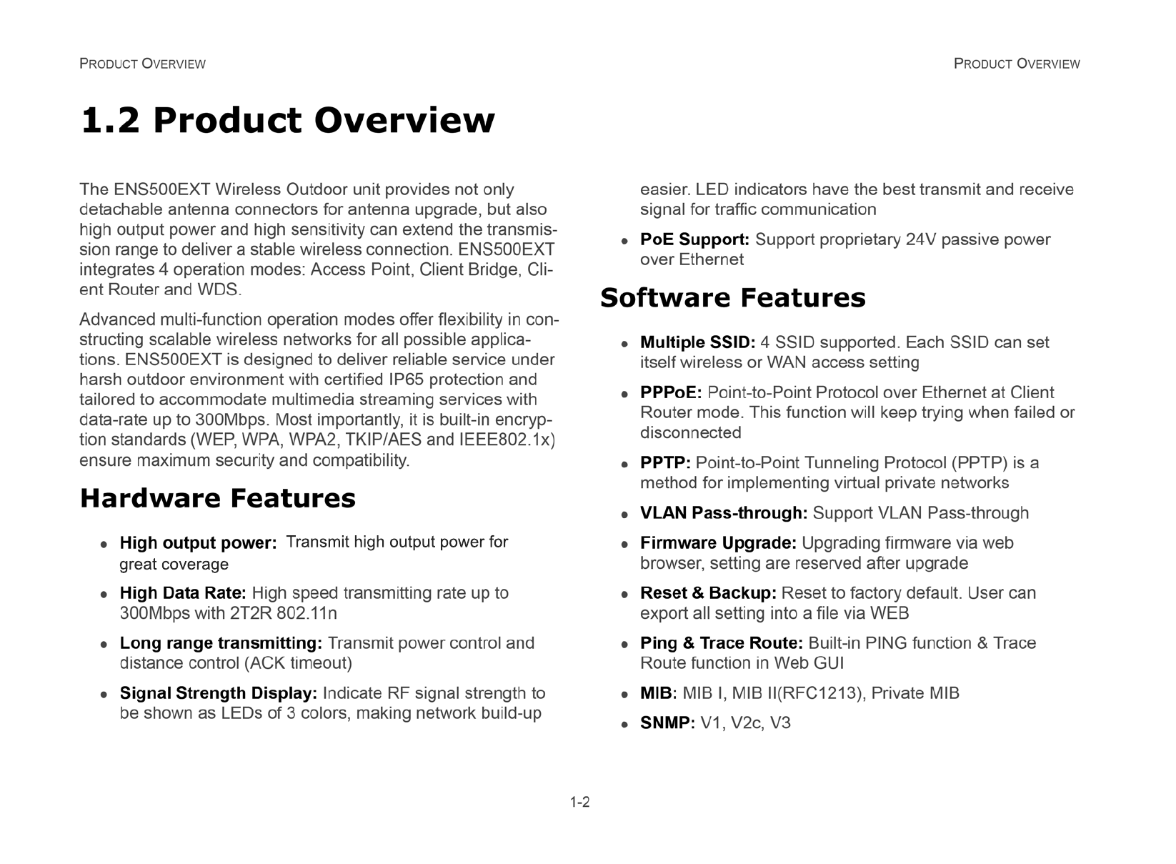
Figure 1-1: Back Panel View
AB C D
E
BACK PANEL VIEW DESCRIPTION
A Power LED OFF = ENS500EXT is not receiving power
ON = ENS500EXT is receiving power
B LAN (2) LEDs
OFF = ENS500EXT is not connected to the
network.
ON = ENS500EXT is connected to the
network, but not sending or receiving data
Blink = ENS500EXT is sending or receiving
data
CWLAN LED
(Access Point or Client Bridge Mode)
OFF = ENS500EXT radio is off and the
device is not sending or receiving data over
the wireless LAN.
ON = ENS500EXT radio is on, and the
device is not sending or receiving data over
the wireless LAN.
Blinking = ENS500EXT radio is on, and the
device is sending or receiving data over the
wireless LAN.
D Signal Indicator LED
(Client Bridge or WDS Station Mode)
Green - Signal is good
Orange - Signal is normal
Red - Signal is weak or non-existent
E Antenna Connectors
PRODUCT OVERVIEW PRODUCT LAYOUT
1-7
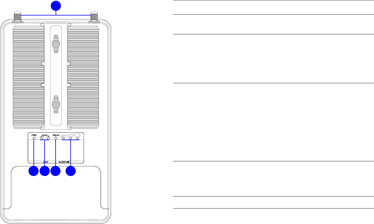
BOTTOM VIEW DESCRIPTION
A Reset Button To reset to factory settings, press button for >
10 seconds.
B LAN Connector
To configure the ENS500EXT, connect an
Ethernet cable to an Ethernet adapter on a
computer. For more information about
configuring individual features, see Logging
In.
C PoE LAN Connector The PoE interface allows the ENS500EXT to
be powered using the supplied PoE injector
AB C
Installation
Chapter 2

INSTALLATION SYSTEM REQUIREMENTS
2-1
2.1 System Requirements
To install the ENS500EXT, you need the following:
Computer (Windows, Linux, Mac OS X Operating System)
Web Browser (Internet Explorer, FireFox, Chrome, Safari)
Network Interface equipped: (one of the following)
Wired connectivity: Network Interface with an open
RJ-45 Ethernet Port
Wireless Connectivity:
Embedded 802.11n Wi-Fi wireless networking, IEEE
802.11a/b/g compatible
Wi-Fi Card, USB Wi-Fi Dongle (802.11 a/n)
An existing router or access point (AP) with SSID broad-
cast
1x CAT5e Ethernet Cable
Note:
The minimum requirement for Ethernet cable power
supply usage is CAT5e.
INSTALLATION INSTALLING THE DEVICE
2-2
2.2 Installing the Device
Installing the ENS500EXT on a pole or wall optimizes the wire-
less access range.
Pre-Installation Guidelines
Select the optimal location for the equipment using the following
guidelines:
The ENS500EXT should be mounted on a pole 1" to 4"
(2.54cm to 10.16cm) in diameter. Its location should
enable easy access to the unit and its connectors for
installation and testing.
The higher the placement of the antenna, the better the
achievable link quality.
The antenna should be installed to provide a direct, or
near line of sight with the Base Station antenna. The
antenna should be aligned to face the general direction of
the Base Station.
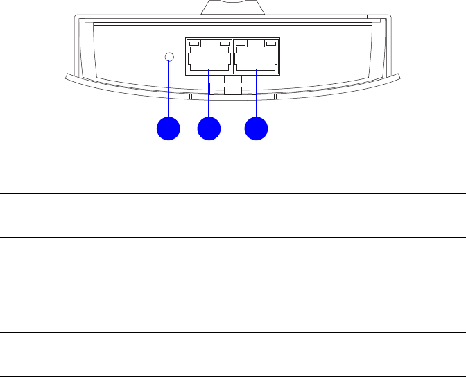
Installing the Device
To install the ENS500EXT, use the following procedure to
mount the device on a pole and refer to the figure below.
1. Remove the bottom cover protecting the RJ-45 connec-
tors.
Figure 2-1: Removing the RJ-45 Port Cover
Note:
Only experienced installation professionals who are
familiar with local building and safety codes and, wherever
applicable, are licensed by the appropriate government
regulatory authorities should install the ENS500EXT.
INSTALLATION INSTALLING THE DEVICE
2-3
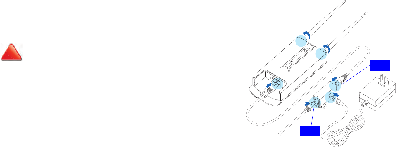
2. Insert an Ethernet cable into the RJ-45 port labeled LAN
(PoE) on the ENS500EXT.
3. Plug the other end of the Ethernet cable into the PoE port
of the PoE injector.
4. Remove the power cord and PoE injector from the box
and plug the power cord into the DC port of the PoE injec-
tor.
5. Plug another Ethernet cable into the LAN port of the PoE
injector and connect the other end of Ethernet cable to
the LAN port of the PC.
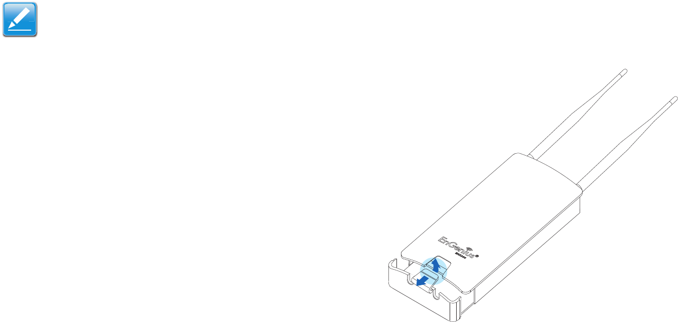
Figure 2-2: Installing the ENS500EXT
6. Attach and secure the two antennas to the top of the
ENS500EXT.
CAUTION!
ONLY USE THE POWER ADAPTER SUPPLIED WITH THE
ENS500EXT. USING A DIFFERENT POWER ADAPTER MIGHT
DAMAGE THE ENS500EXT.
!
PoE
LAN
INSTALLATION INSTALLING THE DEVICE
2-4
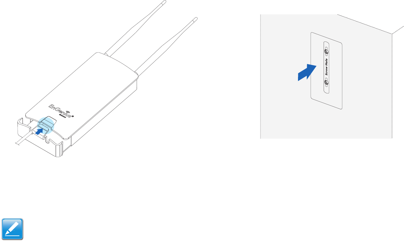
7. Install the bottom cover securely to protect the RJ-45 con-
nectors.
Figure 2-3: Installing the RJ-45 Port Cover
8. Turn over the ENS500EXT.
To mount the ENS500EXT on a wall or a pole, follow these
steps:
Wall mount:
1. Secure the adhesive label to a position on the wall where
you would like to install the ENS500EXT.
Figure 2-4: Screw Layout Adhesive Label
Note:
Find a position for the ENS500EXT that provides the best
signal.
INSTALLATION INSTALLING THE DEVICE
2-5
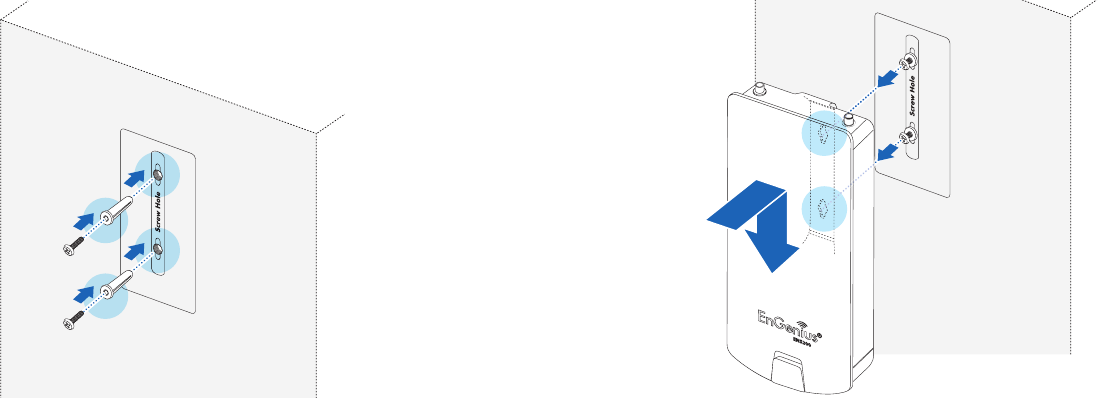
2. Follow the plotting sticker, drill two holes, and secure the
plastic anchors.
Figure 2-5: Wall Mount (1 of 2)
3. Install two screws into the plastic anchors, leaving
enough of the screw protruding out to hang the
ENS500EXT on.
4. Align the screw holes on the mounting bracket with the
screws and then install the device on the wall.
Figure 2-6: Wall Mount (2 of 2)
INSTALLATION INSTALLING THE DEVICE
2-6
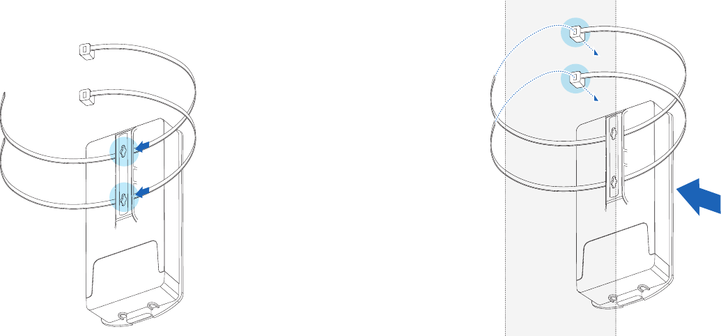
Pole mount:
1. Thread two cable ties through the mounting bracket on
the back of the ENS500EXT.
Figure 2-7: Pole Mount (1 of 2)
2. Position the ENS500EXT on a pole and secure both
cable ties.
Figure 2-8: Pole Mount (2 of 2)
This completes the installation procedure.
Web Configuration
Chapter 3
WEB CONFIGURATION LOGGING IN
3-1
3.1 Logging In
The ENS500EXT has a built-in Web Configurator that lets you
manage the unit from any location using a Web browser that
supports HTTP and has Javascript installed.
After configuring the computer for TCP/IP using the procedure
appropriate for your operating system, use that computer’s
Web browser to log in to the ENS500EXT Web Configurator.
1. Launch your Web browser.
2. In the browser address bar, type 192.168.1.1 and
press the Enter key.
Figure 3-1: Web Browser Address Bar
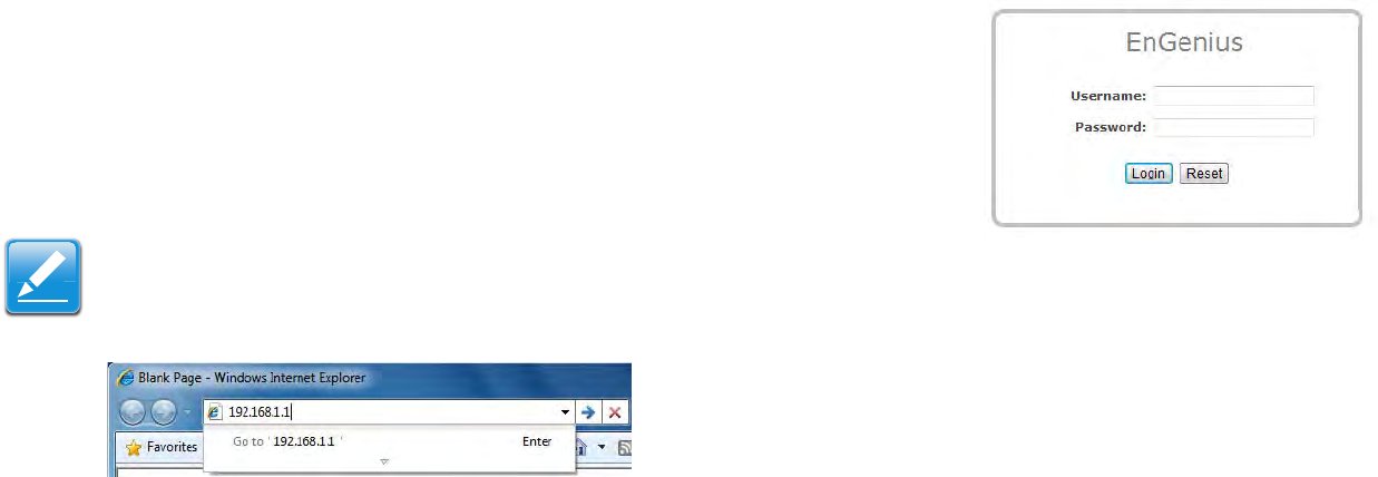
3. When the login screen appears, enter admin for the user-
name in the top field and admin for the password in the bottom
field.
Figure 3-2: Windows Security Login Dialog
4. Click Login to continue or Reset to abort the login.
You are now ready to use the instructions in the following chap-
ters to configure the ENS500EXT.
Note:
If you changed the ENS500EXT LAN IP address, enter the
correct IP address.
WEB CONFIGURATION BEST PRACTICES
3-2
Best Practices
Perform the following procedures regularly to make the
ENS500EXT more secure and manage the ENS500EXT more
effectively.
Change the default password Use a password that is
not easy to guess and that contains different characters,
such as numbers and letters. The ENS500EXT username
cannot be changed. For more information, see Configur-
ing Administrator Account.
Back up the configuration and be sure you know how to
restore it. Restoring an earlier working configuration can
be useful if the ENS500EXT becomes unstable or
crashes. If you forget your password, you will have to
reset the ENS500EXT to its factory default settings and
lose any customized override settings you configured.
However, if you back up an earlier configuration, you will
not have to completely reconfigure the ENS500EXT. You
can simply restore your last configuration. For more infor-
mation, see Configuring Backup/Restore Settings.
Basic Network Settings
Chapter 4
BASIC NETWORK SETTINGS SYSTEM STATUS
4-1
4.1 System Status
View the summary of the current system status including system (hardware/software version, date/time), wired network (LAN) and
wireless network (WLAN) information.
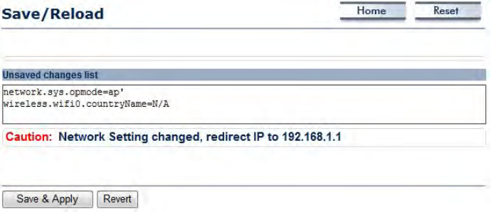
4.1.1 Using Save/Reload
Save and apply the settings shown in the Unsaved changes list,
or cancel the unsaved changes and revert to the previous set-
tings that were in effect.
BASIC NETWORK SETTINGS VIEWING SYSTEM INFORMATION
4-2
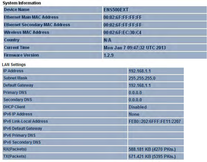
4.1.2 Viewing System Information
Displays status information about the current operating mode.
System Information shows the general system information
such as operating mode, system up time, firmware version, serial
number, kernel version, and application version.
LAN Settings shows Local Area Network settings such as the
LAN IP address, subnet mask, and MAC address.
BASIC NETWORK SETTINGS VIEWING SYSTEM INFORMATION
4-3
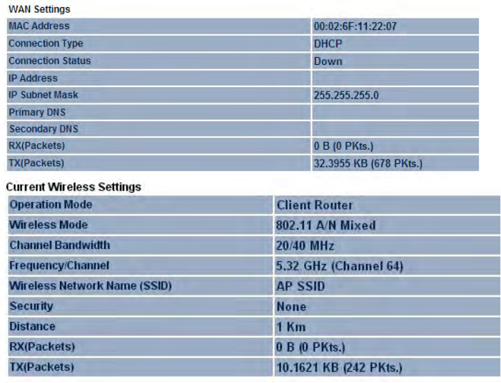
WAN Settings shows Wide Area Network settings such as the
MAC address, connection type, connection status, WAN IP
address, subnet mask, primary and secondary DNS.
Current Wireless Settings shows wireless information such as
frequency and channel. Since the ENS500EXT supports
multiple-SSIDs, information about each SSID, such as its ESSID
and security settings, are displayed.
BASIC NETWORK SETTINGS VIEWING WIRELESS CLIENT LIST
4-4
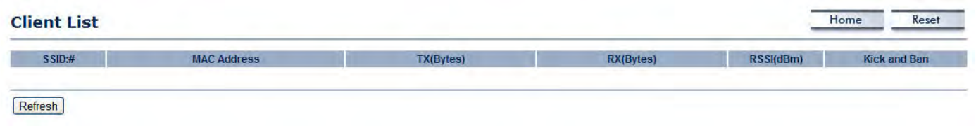
4.1.3 Viewing Wireless Client List
Displays a list of clients associated to the ENS500EXT, along with the MAC addresses and signal strength for each client. To remove
an SSID client from the list, click the button that appears in the Kick and Ban column.
Click the Refresh button to update the client list.
BASIC NETWORK SETTINGS VIEWING SYSTEM LOG
4-5
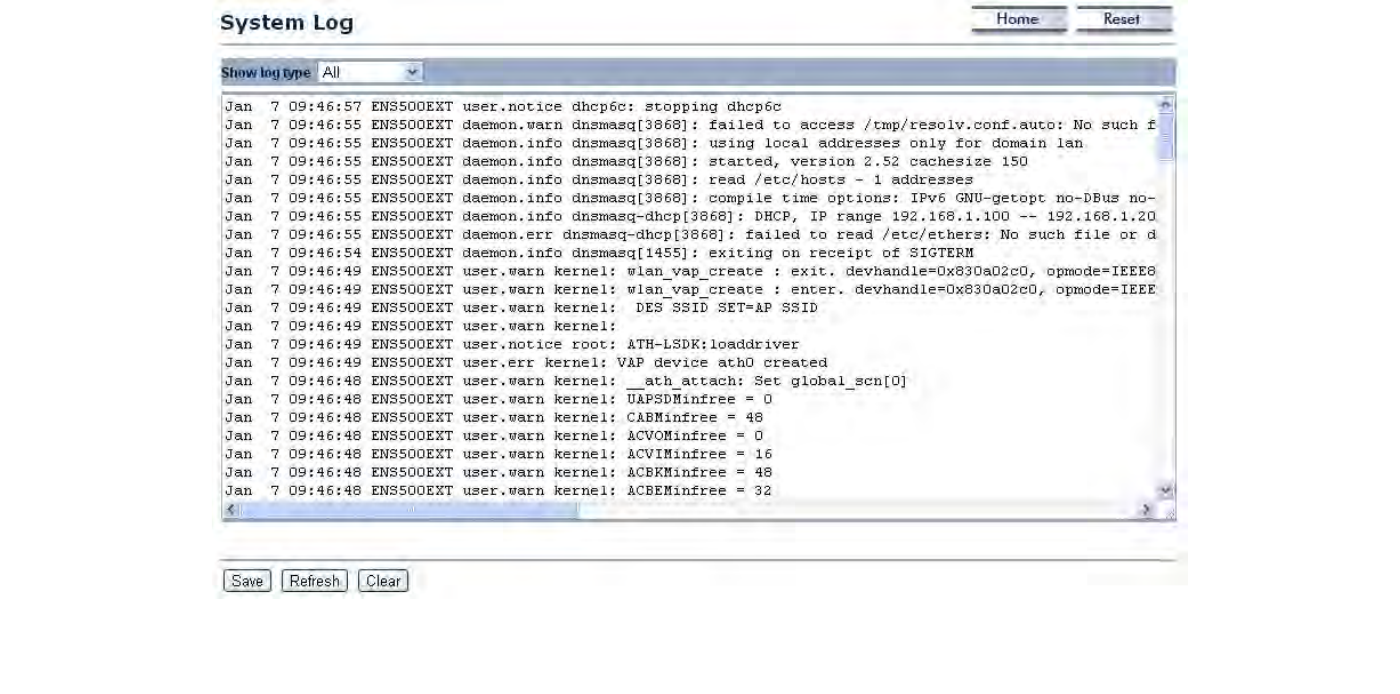
4.1.4 Viewing System Log
The ENS500EXT automatically logs events to internal memory.
Note:
The oldest events are deleted from the log when memory is full.
Click the Save button to save the log information to a text file, click the Refresh button to update the client list, or the Clear button
to remove all events.
BASIC NETWORK SETTINGS VIEWING CONNECTION STATUS
4-6
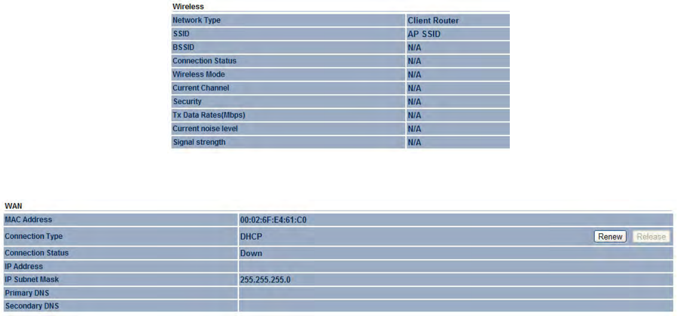
4.1.5 Viewing Connection Status
Displays the current status of the network.
The WLAN information shown includes network type, SSID, BSSID, connection status, wireless mode, current channel, security, data
rate, noise level, and signal strength.
The WAN information shown includes the MAC address, connection type, connection status, IP address, IP subnet mask, primary
DNS and secondary DNS.
Click the Refresh button to update connections status.
BASIC NETWORK SETTINGS VIEWING DHCP CLIENT TABLE
4-7
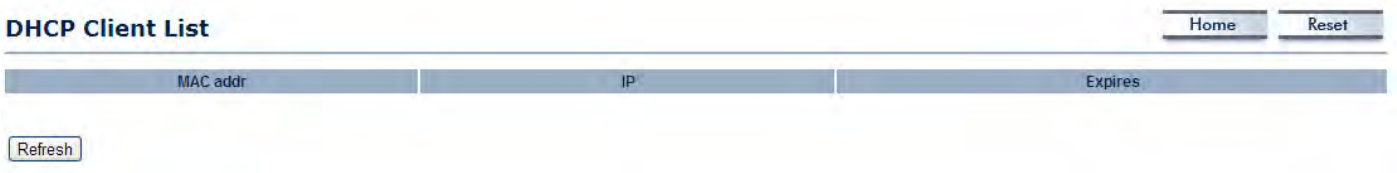
4.1.6 Viewing DHCP Client Table
Displays the clients that are associated to the ENS500EXT through DHCP. The MAC addresses, IP addresses, and expiry times
period for each client are shown in separate rows.
Click the Refresh button to update the client table.
BASIC NETWORK SETTINGS VIEWING WDS LINK LIST
4-8
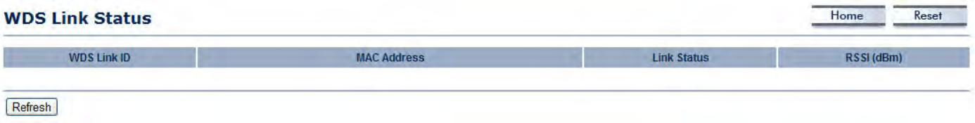
4.1.7 Viewing WDS Link List
Displays the clients that are associated to the ENS500EXT through WDS. The MAC addresses, link status and signal strength for
each client are also shown.
Click the Refresh button to update the client list.
BASIC NETWORK SETTINGS CONFIGURING IP SETTINGS
4-10
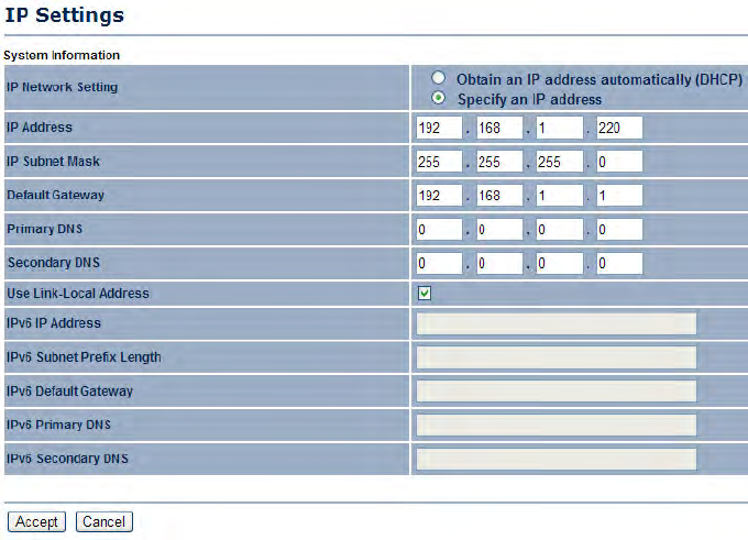
4.2.2 Configuring IP Settings
Configure the ENS500EXT LAN settings for the ENS500EXT using a static or dynamic IP address.
IP Network Setting Configure the network connection type using
either a static IP or dynamic IP.
IP Address Enter the LAN IP address of the ENS500EXT.
Subnet Mask Enter the subnet mask of the ENS500EXT.
Default Gateway Enter the default gateway of the ENS500EXT.
Primary DNS Enter the primary DNS address of the
ENS500EXT.
Secondary DNS Enter the secondary DNS address of the
ENS500EXT.
Use Link-Local Address Click to enable a link-local address for
the device.
IPv6 IP Address Enter the IPv6 LAN IP address of the
ENS500EXT.
IPv6 Subnet Prefix Length Enter the IPv6 subnet prefix length of
the ENS500EXT.
IPv6 Default Gateway Enter the IPv6 default gateway of the ENS500EXT.
IPv6 Primary DNS Enter the IPv6 primary DNS of the ENS500EXT.
IPv6 Secondary DNS Enter the IPv6 secondary DNS of the ENS500EXT.
Click Apply to save the settings or Cancel to discard changes.
BASIC NETWORK SETTINGS CONFIGURING SPANNING TREE SETTINGS
4-11
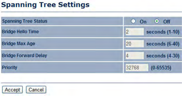
4.2.3 Configuring Spanning Tree Settings
Spanning Tree Status Enable or disable the ENS500EXT
Spanning Tree function.
Bridge Hello Time Specify Bridge Hello Time, in seconds. This
value determines how often the ENS500EXT sends hello
packets to communicate information about the topology
throughout the entire Bridged Local Area Network
Bridge Max Age Specify Bridge Max Age, in seconds. If another
bridge in the spanning tree does not send a hello packet for a
long period of time, it is assumed to be dead.
Bridge Forward Delay Specify Bridge Forward Delay, in
seconds. Forwarding delay time is the time spent in each of the
Listening and Learning states before the Forwarding state is
entered. This delay is provided so that when a new bridge comes
onto a busy network, it looks at some traffic before participating.
Priority Specify the Priority number. Smaller numbers have greater priority.
Click Accept to confirm the changes or Cancel to cancel and return previous settings.
BASIC NETWORK SETTINGS ROUTER SETUP
4-12
4.3 Router Setup
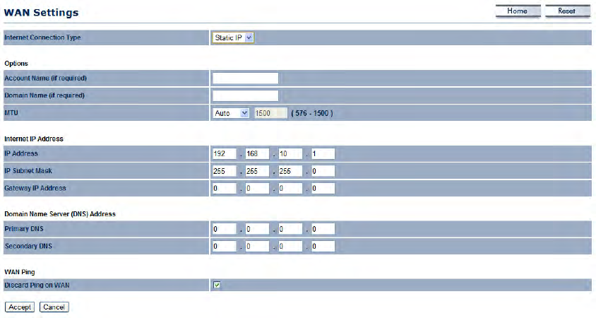
4.3.1 Configuring WAN Settings
Configure the WAN settings for the ENS500EXT using a static or dynamic IP address, PPPoE or PPTP.
Static IP
Setting a static IP address allows an administrator
to set a specific IP address for the router and guar-
antees that it can not be assigned a different
address.
Account Name Enter the account name provided
by your ISP.
Domain Name Enter the domain name provided
by your ISP.
MTU The maximum transmission unit (MTU)
specifies the largest packet size permitted for an
internet transmission. The factory default MTU size
for static IP is 1500. The MTU size can be set
between 512 and 1500.
IP Address Enter the router’s WAN IP address.
Subnet Mask Enter the router’s WAN subnet
mask.
Default Gateway Enter the WAN gateway address.
Primary DNS Enter the primary DNS server address.