EnGenius Technologies ENS500AC AC867 5GHz Outdoor CPE User Manual Users Maual rev
EnGenius Technologies AC867 5GHz Outdoor CPE Users Maual rev
Contents
- 1. Users Maual (EnStation5-AC)_rev.pdf
- 2. Users Maual_rev.pdf
Users Maual_rev.pdf
User Manual
Business Solutions
11AC Wave2 Outdoor Access Point / CPE
ENS500-AC/ENS500EXT-AC/
ENS610EXT/ENS620EXT
version 1.1
2
IMPORTANT
To install this Access Point please refer to the
Quick Installation Guide included in the product packaging.
3
Chapter 1 Product Overview............................................... 4
Introduction...................................................................................... 5
TechnicalSpecications..............................................................8
Physical Interface.......................................................................... 16
Chapter 2 Before You Begin................................................. 19
Computer Settings....................................................................... 20
Hardware Installation................................................................. 24
Mounting the AP........................................................................... 25
InstallGroundcable.....................................................................28
Chapter 3 Conguring Your Access Point......................... 29
Default Settings./Web Conguration................................ 30
Chapter 4 Building a Wireless Network........................... 31
Access Point Mode...................................................................... 32
Client Bridge Mode...................................................................... 33
WDS AP Mode.............................................................................. 35
WDS Bridge Mode........................................................................ 36
WDS Station Mode....................................................................... 37
Chapter 5 Status.................................................................... 38
Overview.......................................................................................... 39
Connection...................................................................................... 41
Realtime............................................................................................ 41
Chapter 6 Network .............................................................. 43
Basic IPv4/IPv6 Settings.......................................................... 44
Spanning Tree Protocol Setting............................................. 44
Chapter 7 2.4 GHz/5 GHz Wireless....................................... 46
Wireless Settings............................................................................ 47
2.4GHz/5GHzWirelessNetwork...........................................48
2.4GHz/5GHzSSIDProle......................................................50
Wireless Security.......................................................................... 51
Wireless MAC Filtering............................................................... 54
Wireless Advanced..................................................................... 55
Fast Roaming.................................................................................. 56
WDS Link Settings....................................................................... 57
GuestNetworkSettings............................................................58
Chapter 8 Management ........................................................ 58
Management VLAN Settings.................................................. 60
Advanced Settings....................................................................... 61
Time Zone........................................................................................ 64
Auto Reboot Settings................................................................ 65
Wi-Fi Scheduler............................................................................... 66
Tools.................................................................................................. 67
Account/Firmware........................................................................ 70
Backup/Restore ............................................................................. 71
Log.................................................................................................... 73
Logout/Reset................................................................................. 74
Appendix................................................................................. 75
FCC Interference Statement................................................... 76
CE Interference Statement...................................................... 77
Professional Installation Instruction................................... 80
Table of Contents

4
Chapter 1
Product Overview
5
Key Features - ENS620EXT
• Upto26dBmtransmitpowerenablinglongrangeconnectivity
• SupportsIEEE802.11acwave2/ac/a/b/g/nwirelessstandards
withupto400Mbpsdatarateon2.4GHzbandand867Mbpson
5GHz band
• SupportWave2MU-MIMOfunctionon5GHzradio.
• SupportTxBeamformingtoenlargethetransmittingdistance.
• Perform256-QAMtoenhanceairperformanceupto400Mbps
under the 2.4GHz radio
• Twodetachable5dBi2.4GHzOmni-directionalantennas
• Twodetachable5dBi5GHzOmni-directionalantennas
• Proprietary24VInputdesignwithGigabitsportsupports.
• Flexibleapplicationbythebuilt-in2ndLANport.
• MorecustomizeditemsonBandSteeringforintellgentManage-
ment.
• TrafcShapingtocontrolbandwidthperSSID/user
• SecuredGuestNetworkoptionavailable
TheAPis802.11acwave2/a/b/g/nOutdoorAccessPoint
with speeds up to 400 Mbps on 2.4GHz and 867Mbps
on 5GHz band. It can be congured as an Access Point,
ClientBridge,orWDS(AP,Station&Bridge).TheAPisan
affordable solution which is built in high-powered radios
and long-range settings to replace the ordinary Access
Introduction
Points that do not have the range and reach to connect to
agrowingnumberofwirelessusers.WithWave2features,
the Access Point could reduce the handling period on client
devices and network with more client devices at the same
time.Meanwhile,thebeamformingwillgatherenergytoa
specicdirectionandincreasethetransmittingdistance.
Introduction
6
Key Features - ENS500-AC/ENS500EXT-AC
• Upto23dBmtransmitpowerenablinglongrangeconnectivity
• SupportsIEEE802.11acwave2/ac/nwirelessstandardswithup
to867Mbpson5GHzband
• ENS500EXT-ACANT:Twodetachable5dBi5GHzOmni-
directional antennas
• ENS500-ACANT:14dBi5GHzdirectionalantennas
• SupportWave2MU-MIMOfunctionon5GHzradio.
• SupportTxBeamformingtoenlargethetransmittingdistance.
• Proprietary24VInputdesignwithGigabitsportsupports.
• Flexibleapplicationbythebuilt-in2ndLANport.
• TrafcShapingtocontrolbandwidthperSSID/user
• SecuredGuestNetworkoptionavailable
TheAPis802.11acwave2/ac/a/nOutdoorAccessPoint
with speeds up to 867Mbps on 5GHz band. It can be
conguredasanAccessPoint,ClientBridge,orWDS(AP,
Station&Bridge).TheAPisanaffordablesolutionwhichis
built in high-powered radios and long-range settings
to replace the ordinary Access Points that do not have
the range and reach to connect to a growing number of
wirelessusers.WithWave2features,theAccessPointcould
reduce the handling period on client devices and network
with more client devices at the same time. Meanwhile,
thebeamformingfeatureswillgatherenergytoaspecic
direction and increase the transmitting distance.
Maximum data rates are based on IEEE 802.11 standards. Actual throughput and range may vary depending on many factors including environmental conditions, distance between
devices, radio interference in the operating environment, and mix of devices in the network. Features and specications subject to change without notice. Trademarks and registered
trademarks are the property of their respective owners. For United States of America: Copyright © 2017 EnGenius Technologies, Inc. All rights reserved.
7
System Requirements
The following are the Minimum System Requirements in
ordertocongurethedevice.
• ComputerwithanEthernetinterfaceorwirelessnetworkcapability
• Windows OS (XP, Vista, 7, 8, 10), Mac OS, or Linux-based operating
systems
• Web-BrowsingApplication(i.e.:Edge,InternetExplorer,Firefox,Safari,or
anothersimilarbrowserapplication)
Package Contents
TheENS620EXTpackagecontainsthefollowingitems:*
• AccessPoint
• 2detachable5dBi2.4GHzOmni-directionalAntennas
• 2detachable5dBi5GHzOmni-directionalAntennas
• PoEAdapter(EPA2410GP)
• 3-pinIEC320-C6PowerCord
• PoleMountRingx1
• WallMountScrewSet
• QuickInstallationGuide
*(allitemsmustbeinpackagetoissuearefund):
TheENS500-ACpackagecontainsthefollowingitems:*
• AccessPoint
• PoEAdapter(EPA2406GP)
• 3-pinIEC320-C6PowerCord
• PoleMountRingx1
• WallMountScrewSet
• QuickInstallationGuide
*(allitemsmustbeinpackagetoissuearefund):
TheENS500EXT-ACpackagecontainsthefollowingitems:*
• AccessPoint
• 2detachable5dBi5GHzOmni-directionalAntennas
• PoEAdapter(EPA2406GP)
• 3-pinIEC320-C6PowerCord
• PoleMountRingx1
• WallMountScrewSet
• QuickInstallationGuide
*(allitemsmustbeinpackagetoissuearefund):
8
WDS Bridge
WDS Station
Management
Auto Channel Selection
MultipleSSID:16SSIDs,8SSIDsperRadio
BSSID
SNMP V1/V2c/V3
MIBI/II,PrivateMIB
VLAN Tag/VLAN Pass-through
Clients Statistics
SaveCongurationasUserDefault
Fast Roaming
E-Mail Alert
RADIUSAccounting
Guest Network
TrafcShapingperSSID/user
Control
CLI Supported
DistanceControl(AckTimeout)
802.1XSupplicant(CBMode)
Multicast Supported
Auto Reboot
Obey Regulatory Power
Security
WEPEncryption-64/128/152bit
WPA/WPA2Personal(WPA-PSKusingTKIPorAES)
WPA/WPA2Enterprise(WPA-PSKusingTKIPorAES)
ENS620EXT
Standard:
IEEE802.11acwave2/ac/a/non5GHz
IEEE802.11b/g/non2.4GHz
Antenna
2xdetachable5dBi2.4GHzOmni-directionalAntennas
2xdetachable5dBi5GHzOmni-directionalAntennas
Physical Interface
2x10/100/1000GigabitEthernetPortswithPoEsupport
LAN1Port:Proprietary24VInput
LAN2Port:DataTransmission
LED Indicator
Power
LAN 1
LAN 2
2.4 GHz
5 GHz
Power Requirements
Proprietary24VPoweroverEthernet(PoE),
UseincludedEPA2410GPonly
Operation Modes
Access Point
WDS
Client Bridge
WDS Detail
WDS AP
Technical Specications
9
Hides SSID in beacons
MACaddressltering,upto32MACsperSSID
WirelessSTA(Client)connectionlist
Https Support
SSH Support
QoS (Quality of Service)
ComplaintwithIEEE802.11estandard
Physical/Environment Conditions
Operating:
Temperature:-20°Cto60°C(-4°Fto140°F)
Humidity(non-condensing):90%orless
Storage:
Temperature:-30°Cto80°C(-22°Fto176°F)
Humidity(non-condensing):90%orless
10
WDS Bridge
WDS Station
Management
Auto Channel Selection
MultipleSSID:16SSIDs,8SSIDsperRadio
BSSID
SNMP V1/V2c/V3
MIBI/II,PrivateMIB
VLAN Tag/VLAN Pass-through
Clients Statistics
SaveCongurationasUserDefault
Fast Roaming
E-Mail Alert
RADIUSAccounting
Guest Network
TrafcShapingperSSID/user
Control
CLI Supported
DistanceControl(AckTimeout)
802.1XSupplicant(CBMode)
Multicast Supported
Auto Reboot
Obey Regulatory Power
Security
WEPEncryption-64/128/152bit
WPA/WPA2Personal(WPA-PSKusingTKIPorAES)
WPA/WPA2Enterprise(WPA-PSKusingTKIPorAES)
ENS610EXT
Standard:
IEEE802.11acwave2/ac/a/non5GHz
IEEE802.11b/g/non2.4GHz
Antenna
2xdetachable5dBi2.4GHzOmni-directionalAntennas
2xdetachable5dBi5GHzOmni-directionalAntennas
Physical Interface
2x10/100/1000GigabitEthernetPortswithPoEsupport
LAN1Port:Proprietary24VInput
LAN2Port:DataTransmission
LED Indicator
Power
LAN 1
LAN 2
2.4 GHz
5 GHz
Power Requirements
Proprietary24VPoweroverEthernet(PoE),
UseincludedEPA2406GPonly
Operation Modes
Access Point
WDS
Client Bridge
WDS Detail
WDS AP
11
Hides SSID in beacons
MACaddressltering,upto32MACsperSSID
WirelessSTA(Client)connectionlist
Https Support
SSH Support
QoS (Quality of Service)
ComplaintwithIEEE802.11estandard
Physical/Environment Conditions
Operating:
Temperature:-20°Cto60°C(-4°Fto140°F)
Humidity(non-condensing):90%orless
Storage:
Temperature:-30°Cto80°C(-22°Fto176°F)
Humidity(non-condensing):90%orless
12
ENS500-AC
Standard:
IEEE802.11acwave2/ac/a/non5GHz
Antenna
Internal 14dBi high gain directional antenna
Physical Interface
2x10/100/1000GigabitEthernetPortswithPoEsupport
LAN1Port:Proprietary24VInput
LAN2Port:DataTransmission
LED Indicator
Power
LAN 1
LAN 2
WLAN
Weak
Normal
Strong
Power Requirements
Proprietary24VPoweroverEthernet(PoE),
UseincludedEPA2406GPonly
Operation Modes
Access Point
WDS
Client Bridge
WDS Detail
WDS AP
WDS Bridge
WDS Station
Management
Auto Channel Selection
MultipleSSID:8SSIDs
BSSID
SNMP V1/V2c/V3
MIBI/II,PrivateMIB
VLAN Tag/VLAN Pass-through
Clients Statistics
SaveCongurationasUserDefault
TrafcShapingperSSID/user
E-Mail Alert
RADIUSAccounting
Guest Network
Control
CLI Supported
DistanceControl(AckTimeout)
802.1XSupplicant(CBMode)
Multicast Supported
Auto Reboot
Obey Regulatory Power
Security
WEPEncryption-64/128/152bit
WPA/WPA2Personal(WPA-PSKusingTKIPorAES)
WPA/WPA2Enterprise(WPA-PSKusingTKIPorAES)
13
Hides SSID in beacons
MACaddressltering,upto32MACsperSSID
WirelessSTA(Client)connectionlist
Https Support
SSH Support
QoS (Quality of Service)
ComplaintwithIEEE802.11estandard
Physical/Environment Conditions
Operating:
Temperature:-20°Cto60°C(-4°Fto140°F)
Humidity(non-condensing):90%orless
Storage:
Temperature:-30°Cto80°C(-22°Fto176°F)
Humidity(non-condensing):90%orless
14
ENS500EXT-AC
Standard:
IEEE802.11acwave2/ac/a/non5GHz
Antenna
2xdetachable5dBi5GHzOmni-directionalAntennas
Physical Interface
2x10/100/1000GigabitEthernetPortswithPoEsupport
LAN1Port:Proprietary24VInput
LAN2Port:DataTransmission
LED Indicator
Power
LAN 1
LAN 2
WLAN
Weak
Normal
Strong
Power Requirements
Proprietary24VPoweroverEthernet(PoE),
UseincludedEPA2406GPonly
Operation Modes
Access Point
WDS
Client Bridge
WDS Detail
WDS AP
WDS Bridge
WDS Station
Management
Auto Channel Selection
MultipleSSID:8SSIDs
BSSID
SNMP V1/V2c/V3
MIBI/II,PrivateMIB
VLAN Tag/VLAN Pass-through
Clients Statistics
SaveCongurationasUserDefault
TrafcShapingperSSID/user
E-Mail Alert
RADIUSAccounting
Guest Network
Control
CLI Supported
DistanceControl(AckTimeout)
802.1XSupplicant(CBMode)
Multicast Supported
Auto Reboot
Obey Regulatory Power
Security
WEPEncryption-64/128/152bit
WPA/WPA2Personal(WPA-PSKusingTKIPorAES)
WPA/WPA2Enterprise(WPA-PSKusingTKIPorAES)
ENS500EXT-AC
Standard:
IEEE802.11acwave2/ac/a/non5GHz
Antenna
2xdetachable5dBi5GHzOmni-directionalAntennas
Physical Interface
2x10/100/1000GigabitEthernetPortswithPoEsupport
LAN1Port:Proprietary24VInput
LAN2Port:DataTransmission
LED Indicator
Power
LAN 1
LAN 2
WLAN
Weak
Normal
Strong
Power Requirements
Proprietary24VPoweroverEthernet(PoE),
UseincludedEPA2406GPonly
Operation Modes
Access Point
WDS
Client Bridge
WDS Detail
15
Hides SSID in beacons
MACaddressltering,upto32MACsperSSID
WirelessSTA(Client)connectionlist
Https Support
SSH Support
QoS (Quality of Service)
ComplaintwithIEEE802.11estandard
Physical/Environment Conditions
Operating:
Temperature:-20°Cto60°C(-4°Fto140°F)
Humidity(non-condensing):90%orless
Storage:
Temperature:-30°Cto80°C(-22°Fto176°F)
Humidity(non-condensing):90%orless
16
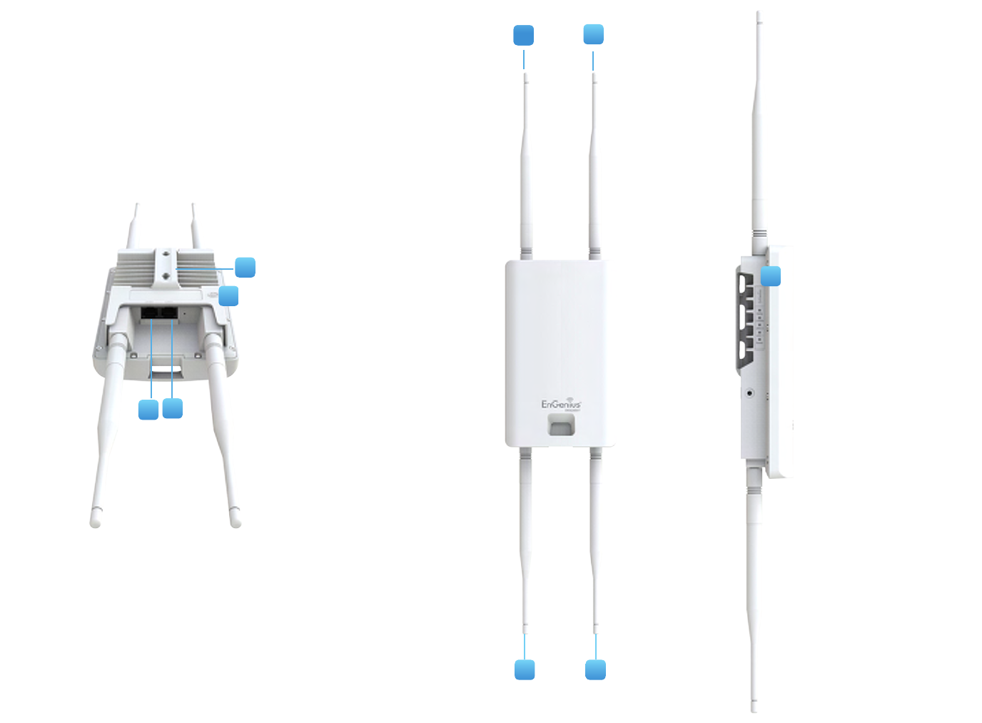
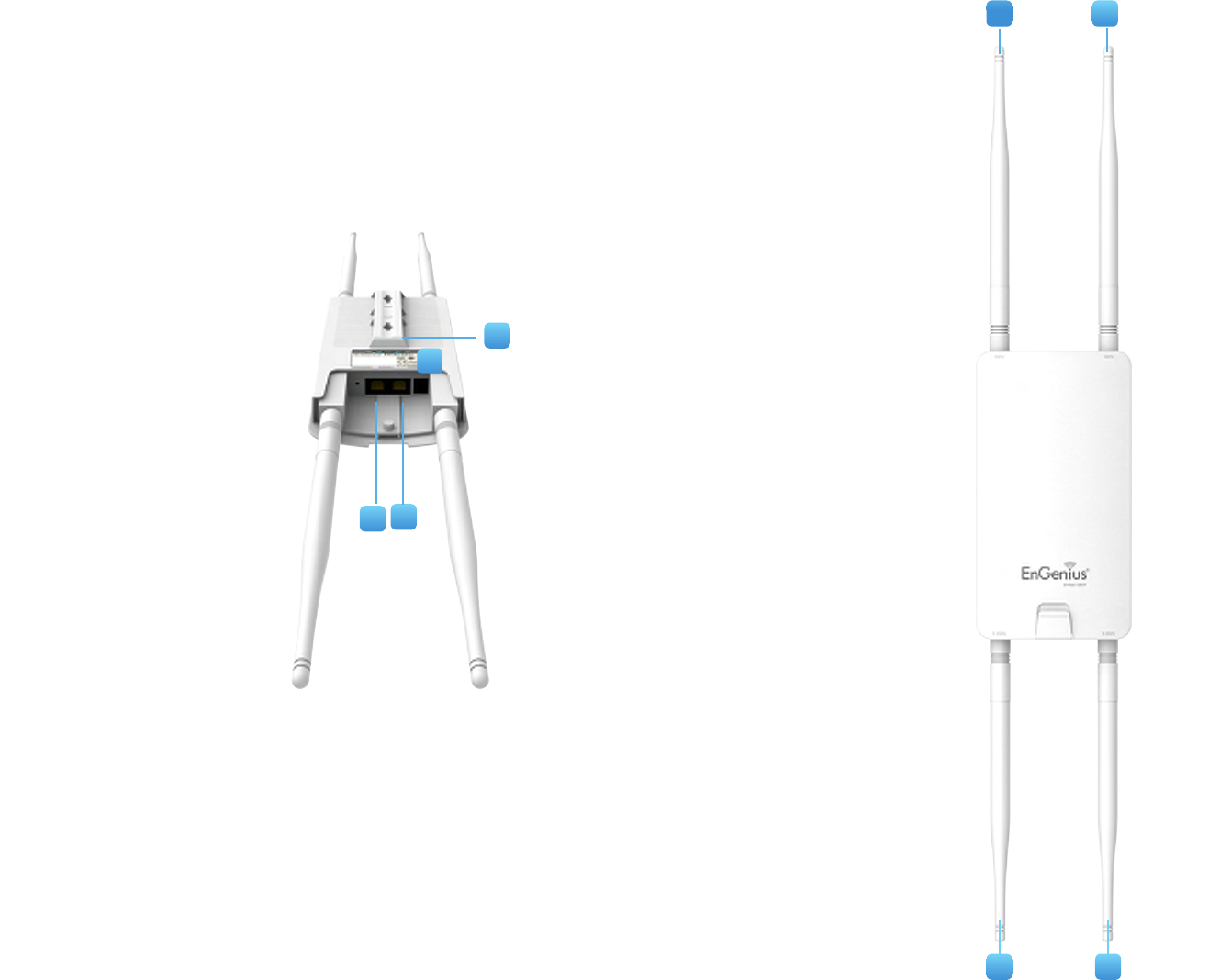
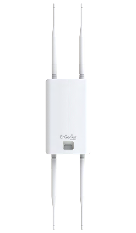
Physical Interface (ENS620EXT)
Dimensions and Weights
Length:191.6mm(7.54”)
Width:114.3(4.49”)
Depth:47.7mm(1.88”)
1 2.4 GHz Antennas: Detachable 5 dBi 2.4 GHz Omni-directional
2 5 GHz Antennas Detachable 5 dBi 5 GHz Omni-directional
3 LAN Port 1 (Proprietary24V PoE):EthernetportforRJ-45cable.
4 LAN Port 2 : EthernetportforRJ-45cable.
5 LED Indicators: LEDlightsforPower,LANPort1,LANPort2,
2.4 GHz Connection and 5 GHz Connection.
6 Ground Cable
7 Mounting Holes:Usingtheprovided hardware, the AP canbe
attached to a wall or pole.
1
6
7
2
2 1
5
3
4
1
17
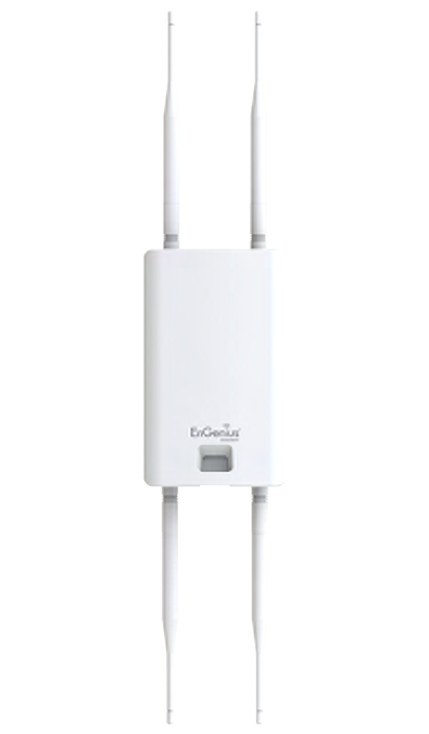
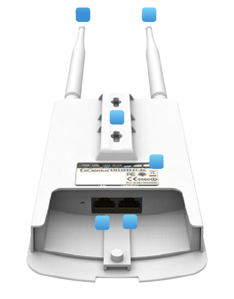
Physical Interface (ENS610EXT)
Dimensions and Weights
Length:191.6mm(7.54”)
Width:114.3(4.49”)
Depth:47.7mm(1.88”)
1 2.4 GHz Antennas: Detachable 5 dBi 2.4 GHz Omni-directional
2 5 GHz Antennas Detachable 5 dBi 5 GHz Omni-directional
3 LAN Port 1 (Proprietary24V PoE):EthernetportforRJ-45cable.
4 LAN Port 2 : EthernetportforRJ-45cable.
5 LED Indicators: LEDlightsforPower,LANPort1,LANPort2,
2.4 GHz Connection and 5 GHz Connection.
6 Mounting Holes:Usingtheprovided hardware, the AP canbe
attached to a wall or pole..
5
6
2
1 1
3
4
2
18
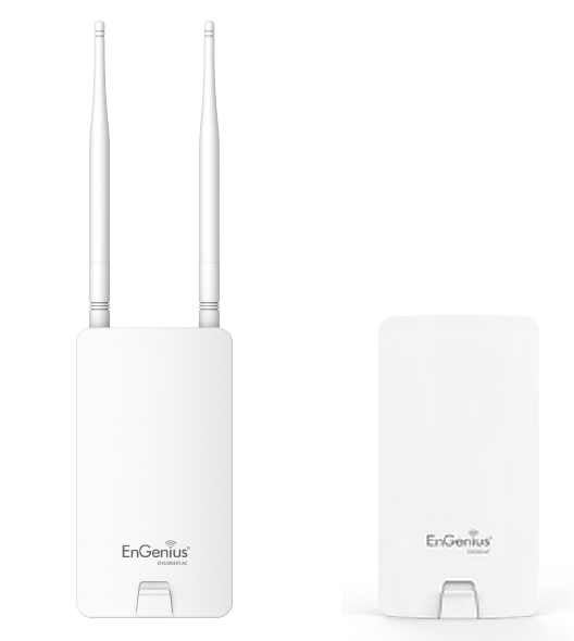
Physical Interface - ENS500-AC/ENS500EXT-AC
Dimensions and Weights
Length:186mm(7.32”)
Width:100(3.94”)
Depth:29mm(1.14”)
1 5 GHz Antennas Detachable 5 dBi 5 GHz Omni-directional
Antennas(ENS500EXT-ACOnly)
2 LAN Port 1 (Proprietary24V PoE):EthernetportforRJ-45cable.
3 LAN Port 2 : EthernetportforRJ-45cable.
4 LED Indicators: LEDlightsforPower,LANPort1,LANPort2,
2.4 GHz Connection and 5 GHz Connection.
5 Mounting Holes:Usingtheprovided hardware, the AP canbe
attached to a wall or pole.
1 1
2
3
4
5

19
Chapter 2
Before You Begin
20
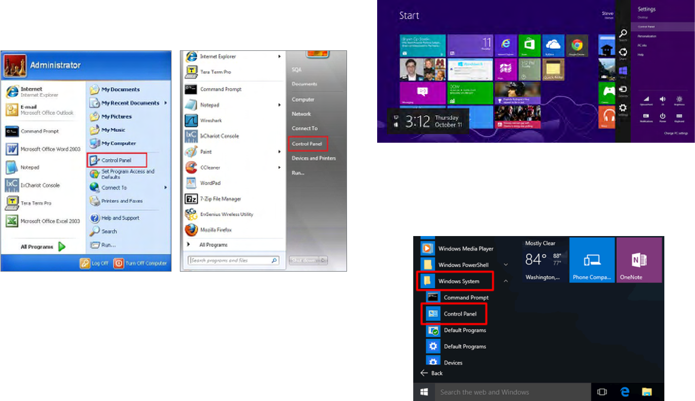
Windows XP/Windows 7/Windows 8/Windows
10
InordertousetheAccessPoint,youmustrstcongurethe
TCP/IPv4 connection of your Windows OS computer system.
1a. Click the Start button and open the Control Panel
1b. Move your mouse to the lower right hot corner to
display the Charms Bar and select the Control Panel in
Windows8OS.
1c. In Windows 10, click Start to select All APPs to enter
the folder of Windows system for selecting Control
Panel.
Computer Settings
Windows XP Windows 7
Windows 8
Windows 10

21
2a. In Windows XP, click Network Connections.
2b. In Windows 7/Windows 8/Windows 10, click View
Network Status and Tasks in the Network and
Internetsection,thenselect Change adapter settings.
3. Right click on Local Area Connection and select Properties.
4. Select Internet Protocol Version 4 (TCP/IPv4) and then
select Properties.
5. Select Use the following IP address and enter an IP
address that is different from the Access Point and Subnet
mask,thenclickOK.
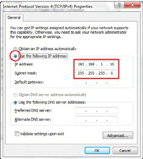
22
Note: Ensure that the IP address and Subnet mask are
on the same subnet as the device.
Forexample:ENH220EXTIPaddress:192.168.1.1
PCIPaddress:192.168.1.2–192.168.1.255
PCSubnetmask:255.255.255.0
23
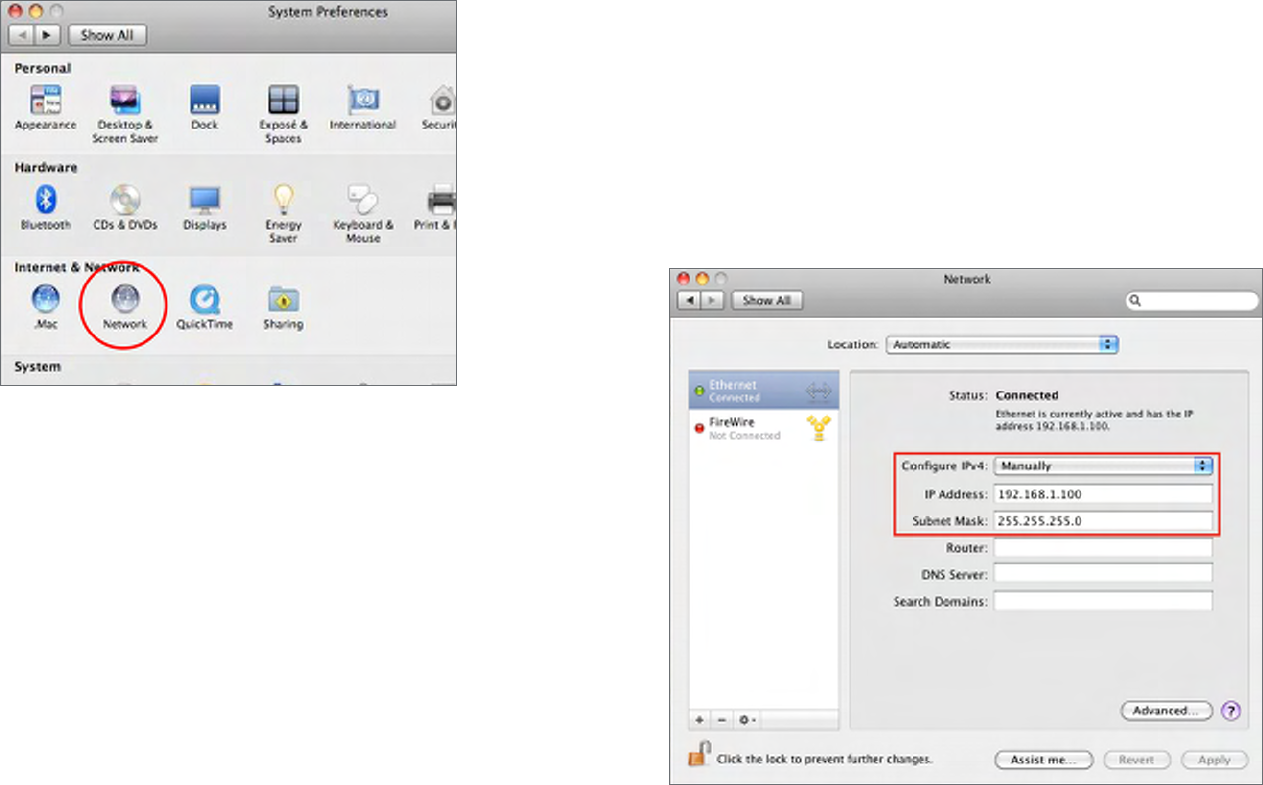
Apple Mac OS X
1. Go to System Preferences(Whichcanbeopenedinthe
ApplicationsfolderorselectingitintheAppleMenu).
2. Select Network in the Internet & Network section.
3. Highlight Ethernet.
4. In Congure IPv4,selectManually.
5. Enter an IP address that is different from the Access
Point and Subnet mask then press OK.
Note: Ensure that the IP address and Subnet mask are
on the same subnet as the device.
Forexample:ENH900EXTIPaddress:192.168.1.1
PCIPaddress:192.168.1.2–192.168.1.255
PCSubnetmask:255.255.255.0
6. Click Apply when done.
24
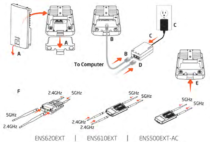
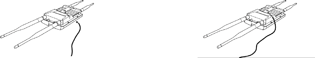
A. Remove the rear bottom panel.
B. ConnectoneendoftheEthernetcableintotheLAN(PoE)
port of the AP/Bridge and the other end to the PE port
on the PoE Adapter.
C. Connect the Power cord with the PoE Adapter and plug
the other end into an electrical outlet.
D. Connect the second Ethernet cable into the LAN port of
the PoE adapter and the other end to the Ethernet port
on the computer.
E. Place the pane removed from step A back into the device.
F. Screw on the provided antennas to the top of this device.
(AppliedontheENS500EXT-AC/ENS610EXT/ENS620EXT)
Thisdiagramdepictsthehardwareconguration.
Note: The Access Point NOLY supports the included
proprietary 24V PoE adapter.
Hardware Installation
25
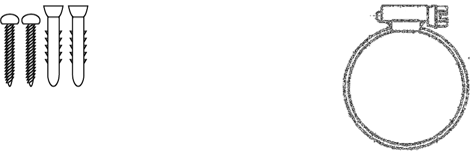
Mounting the AP
Usingtheprovidedhardware,theAPcanbeattachedtoawallorapole.
1. Wall Mounting Kit
(Anchors: Φ5.5*18 mm & Bolts: Φ8*25mm)
2. Pole Mounting Strap
(Φ63.5*12.7 mm)
Bolts
Anchors
26
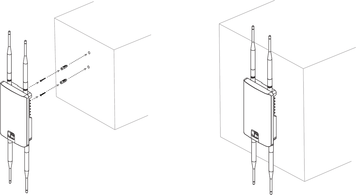
To attach the AP to a wall using wall mounting
kit.
1. Determine where the Access Point to be placed and
mark locations on a surface for the two mounting holes.
Useanappropriatedrillbittodrilltwo8.1mmdiagram
and 26mm depth holes in the markings and hammer the
bolts into the opening.
2. Screwtheanchorsuntotheholesuntiltheyareush
with the wall.
3. Screw the included screws into the anchors.
4. Place this Access Point against wall with the mounting
heads.
1
2
4
3
27
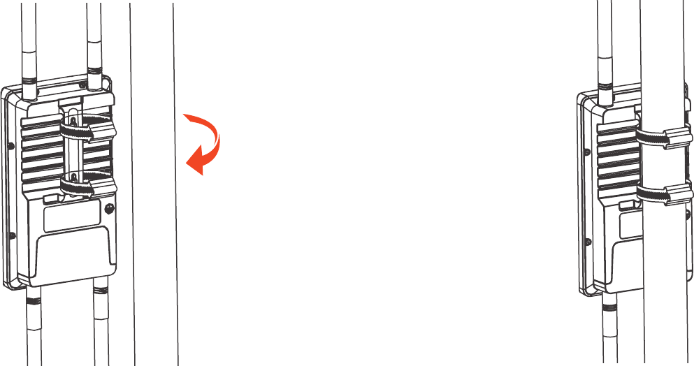
To attach the AP to a pole using the provided
pole mounting kit:
1. Thread the open end of the pole strap through the two
tabs on the Pole Mount Bracket.
2. Lock and tighten pole strap to secure pole mount
bracket to the pole.
12
28
Install Ground cable (ENS620EXT Only)
NooutdoorAPsarebuilttowithstandadirectlightningstrike.TopreventadirectlyligtningstirkeintooutdoorAPs,
they should be properly grounded to a viable path for lightning surge to deliver to ground so that is does not go into the
building network. This AP have a ground lug on the left side of this AP which is applied to attach a proper ground to.
*Attention: You must always install an external grounding wire ensure that you have completed grounding before you connect power
to the unit.

29
Chapter 3
Conguring Your
Access Point
30
This section will show you how to congure the device
usingtheweb-basedcongurationinterface.
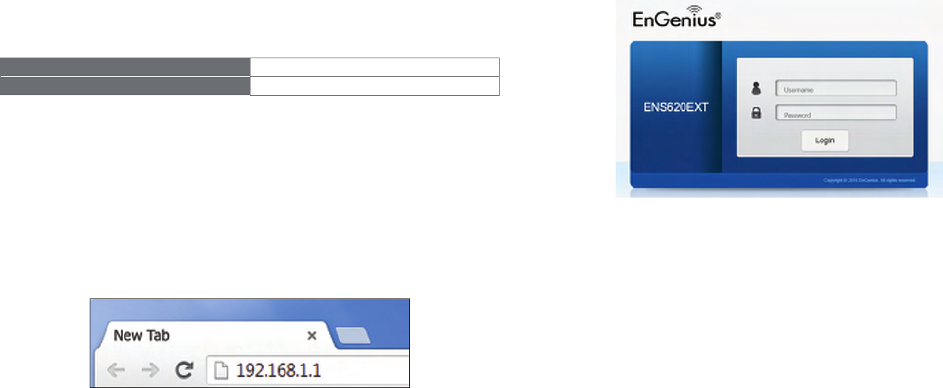
Default Settings
Please use your Ethernet port or wireless network adapter
to connect the Access Point.
IP Address 192.168.1.1
Username / Password admin / admin
Web Conguration
1. Openawebbrowser(InternetExplorer/Firefox/Safari/
Chrome)andentertheIPAddresshttp://192.168.1.1
Note: If you have changed the default LAN IP Address of
theAccessPoint,ensureyouenterthecorrectIPAddress.
2. The default username and password are admin.
Once you have entered the correct username and
password,clicktheLogin button to open the web-base
congurationpage.
*Themodelnamewillbevariedbydifferentmodels.
3. Ifsuccessful,youwillbe loggedin andsee theUser
Menu of this Access Point.
Conguring Your Access Point

31
Chapter 4
Building a Wireless
Network
32
BeforestartingtocongurethisAccessPoint,youmayrealizetheusedscenarioundervariedoperatingmodes.TheAP
has the ability to operate in various modes. This chapter describes purpose of different operating modes and lists down
theoperatingmodesforoutdoorAccessPointsorClientPremiseEquipments(CPE).
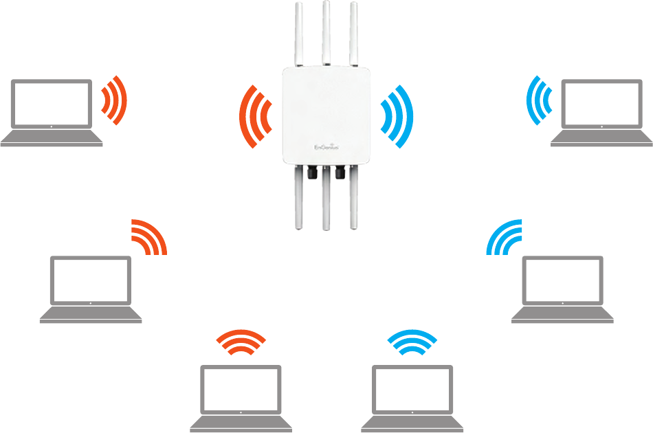
Access Point Mode
InAccessPointMode,APbehaveslikesacentralconnectionforstationsorclientsthatsupportIEEE802.11ac/a/b/g/nnetworks.
ThestationsandclientsmustbeconguredtousethesameSSID(ServiceSetIdentier)andsecuritypasswordtoassociate
with the AP. The AP supports up to eight SSIDs per band at the same time for secure access.
AP
Access Point
Client
Client Client
Client Client
Client
2.4 GHz 5 GHz
33
Client Bridge Mode
The Access Point essentially acts as a wireless adapter that connects to an access point to allow a system of wireless
accesstothenetworkintheClientBridgemode.Sincethecomputersareonthesamesubnet,theAccessPointcan
broadcast to reach all end-devices.
IfyouusetheclientbridgemodeinthisAccessPoint,youcanusetheAPDetectionfeaturetoscanforAccessPoints
withinrange.WhenyoundanAccessPoint,congurethisAccessPointtousethesameSSIDandSecurityPasswordas
the Access Point to associate with it.
34
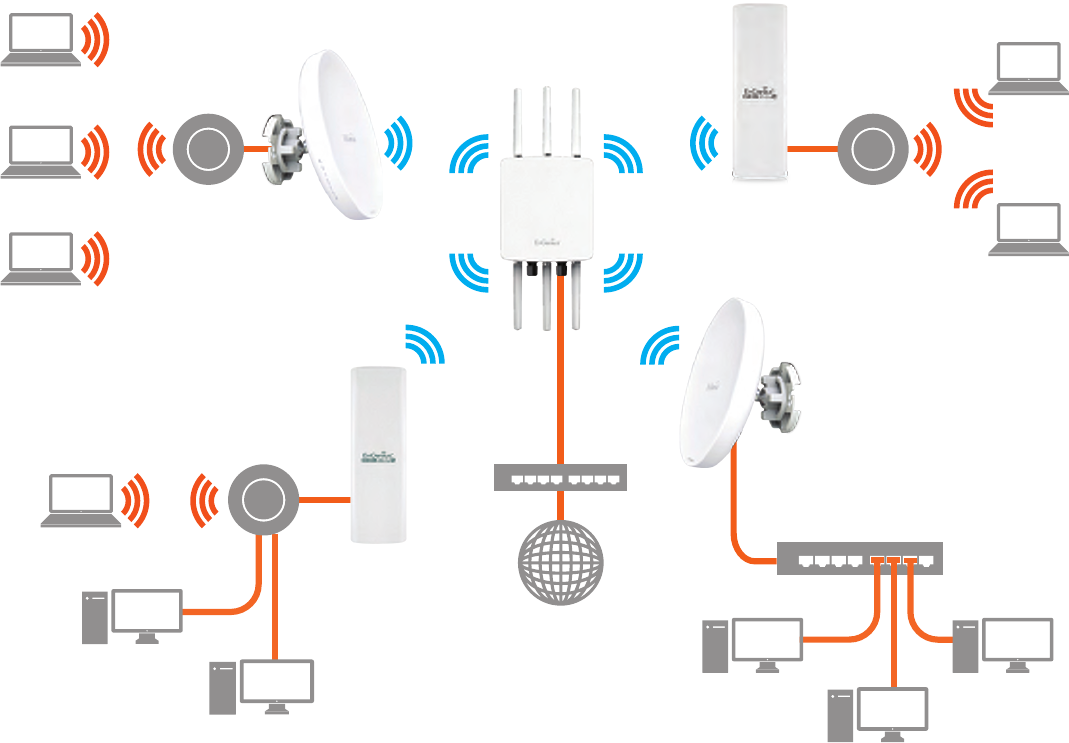
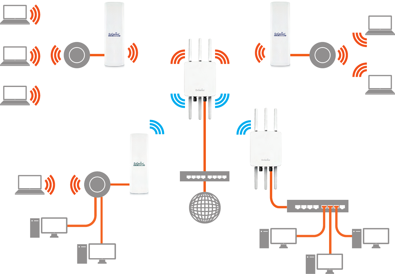
TheAPcanbeusedasacentralizedOutdoorAccessPointwithwhichotherEnGeniusWireless802.11b/g/n2.4orac/a/n
5 GHz Outdoor Client Bridges can associate; leveraging the long-range capability of their internal high-gain directional
antennas,resultinginaverycost-effectivesolutiontoexpandacompanynetworkoveramultiplebuildingcampus.
AP
Access Point
AP
Client Bridge
ENH202
Client Bridge
ENH202
Client Bridge
ENH500
Client Bridge
Client
Client
Client
Client
Client
Client
Client
Client
Client
Client
Client
2.4 GHz
5 GHz 5 GHz
2.4 GHz
Switch
Switch
Internet
35
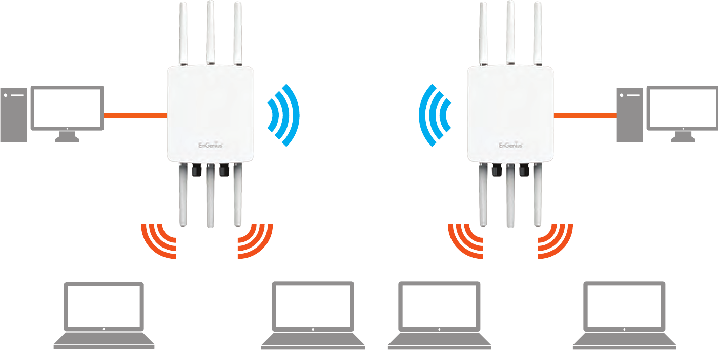
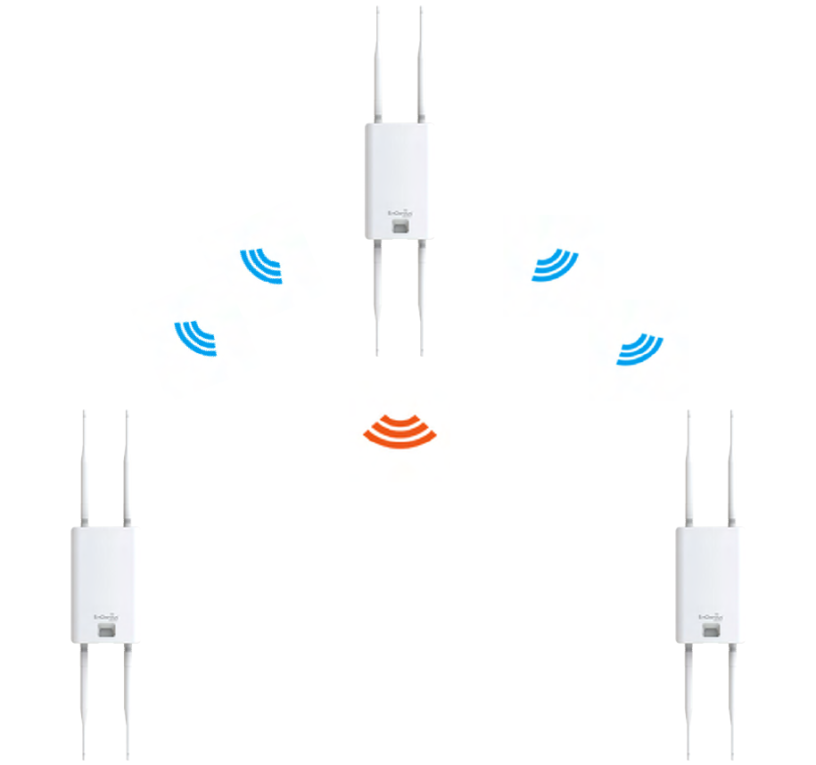
WDS AP Mode
The AP also supports WDS AP mode. This operating mode allows wireless stations to connect with Access Point via using
WDStechnology.Inthismode,conguretheMACaddressesorSSIDsinbothAccessPointstoenlargethewirelessarea
byenablingWDSLinksettings.WDSAPmodesupportsuptofour(4)APMACaddressesandfour(4)SSIDsatthesame
time.
AP
WDS AP
AP
WDS AP
2.4 GHz 2.4 GHz
5 GHz 5 GHz
Client Client Client Client
Client
Computer
Client
Computer
36
WDS Bridge Mode
InWDSBridgeMode,theAccesssPointcanwirelesslyconnectdifferentLANsbyconguringtheMACaddressandsecurity
settingsofeachAccessPoints.UsethisoperatingmodewhentwowiredLANslocatedasmalldistanceapartwantto
communicatewitheachother.ThebestsolutionistousetheAccessPointtowirelesslyconnecttwowiredLANs,as
shown in the following diagram.
WDSBridgeModecanestablishuptofour(4)toeight(8)WDSlinks,creatingastar-likenetwork.
Note: WDS Bridge Mode does not act as an Access Point. Access Points linked by WDS are using the same frequency
channel. More Access Points connected together may lower throughput. This conguration can be susceptible to
generate endless network loops in your network, so it is recommended to enable the Spanning Tree function to
prevent this from happening.
AP
WDS Bridge
AP
WDS Bridge
AP
WDS Bridge
Client
Computer
Client
Computer
Client
Computer
37
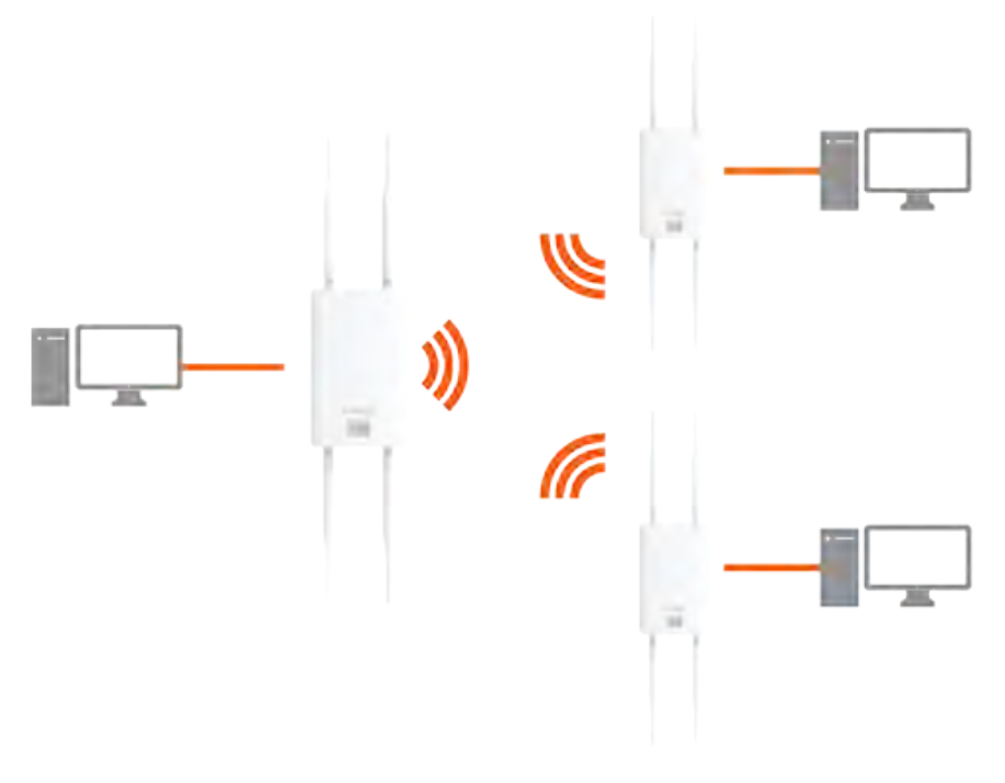
WDS Station Mode
WDSstation(WDSSTA)modeexpandstheWDSbyreceivingawirelesssignal/serviceandsharingitthroughtheEthernet
port.WithWDSSTAmode,
Access Point
WDS AP
on both 5 GHz or 2.4 GHz
Access Point
WDS Station
Access Point
WDS Station

38
Chapter 5
Status
39
Save Changes
This page lets you save and apply the settings shown under
Unsaved changes list,orReverttheunsavedchangesand
revert to the previous settings that were in effect.
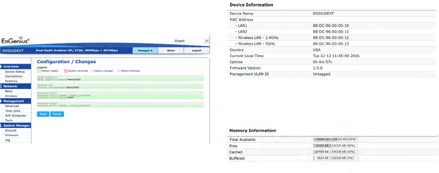
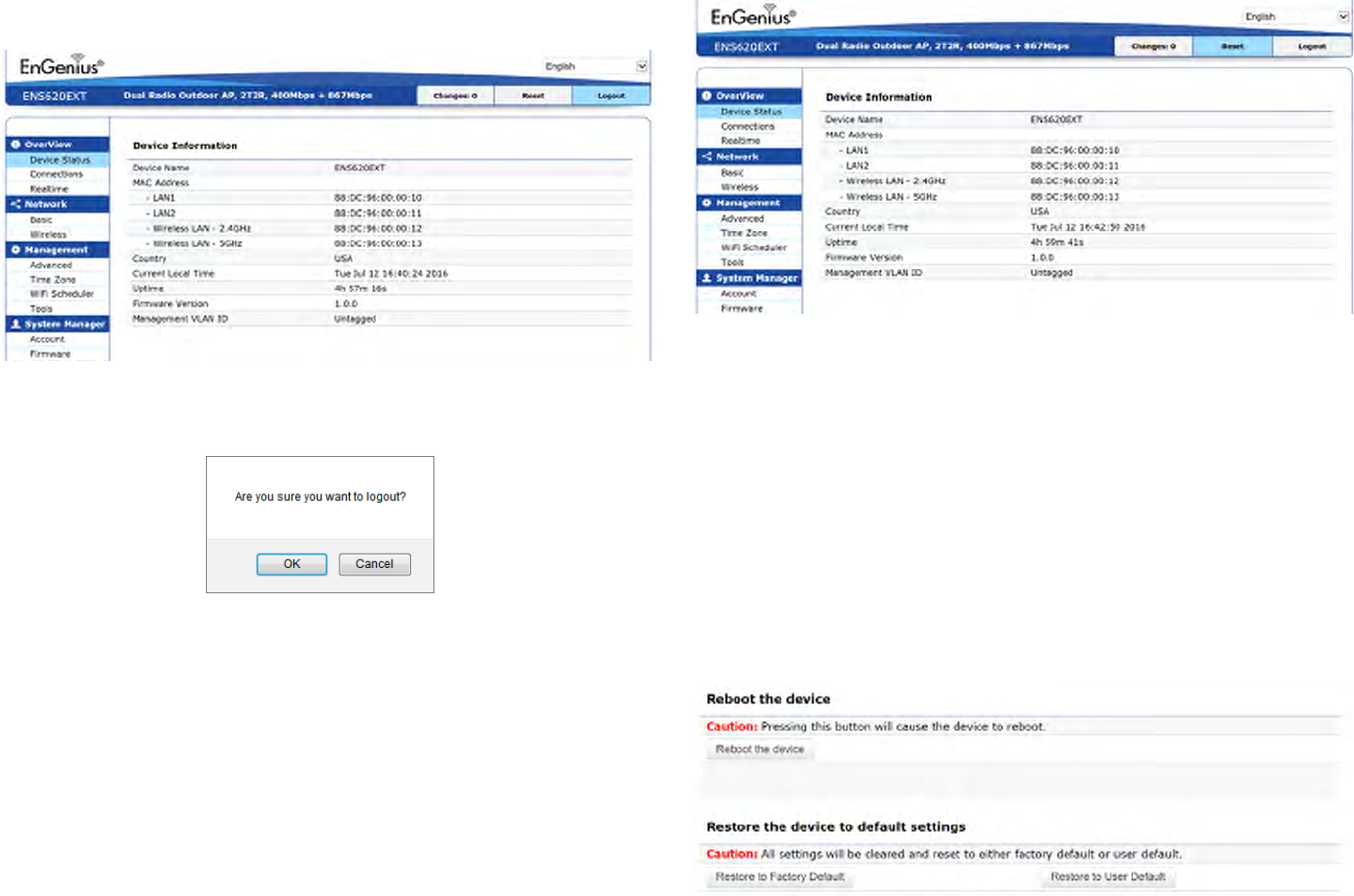
Device Status
Clicking the Device Status link under the Overview menu
shows the status information about the current operating
mode.
• The Device Information section shows general system
informationsuchasDeviceName,MACAddress,Current
Time,FirmwareVersion,andManagementVLANID
Note: VLANIDisonlyapplicableinAccessPoint,WDS
AP or WDS BR mode.
• The Memory Information section shows usage of
memorysuchasTotalAvailable,Free,Cached,Buffered
Overview
40
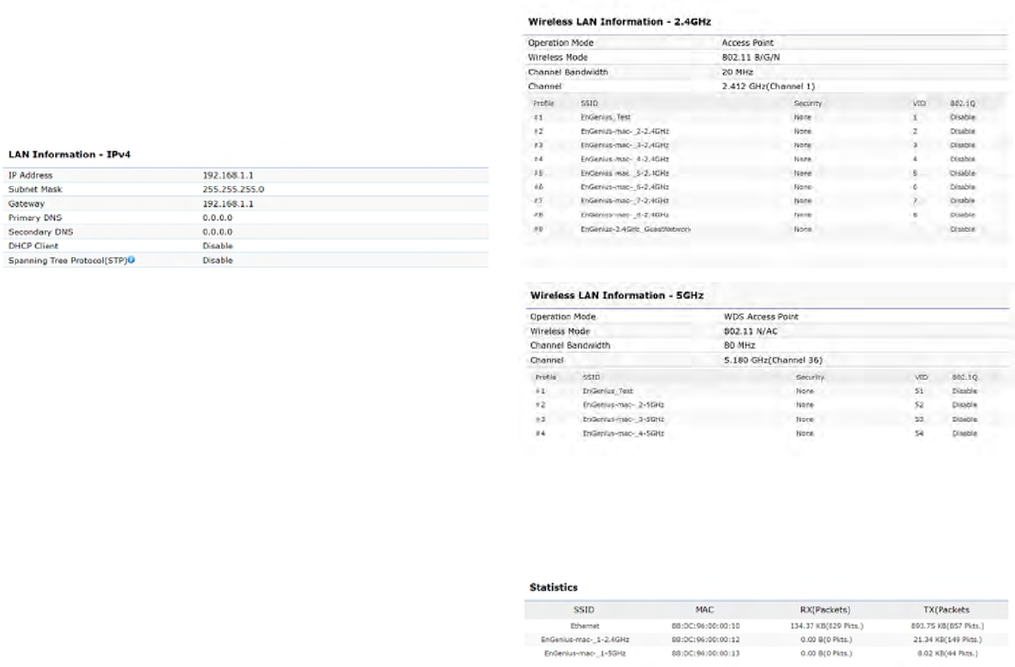
• The LAN Information section shows the Local Area
NetworksettingssuchastheLANIPAddress,Subnet
mask, Primary DNS Address, Secondary DNS Address,
status of DHCP client, and status of Spanning Tree
protocol(STP).
The Wireless LAN Information 2.4 GHz/5 GHz section
shows wireless information such as Operation Mode,
Frequency,andChannel.SincethisAccessPointsupports
multiple-SSIDs,informationabouteachSSID,theESSID,
andsecuritysettings,aredisplayed
Note: ProleSettingsareonlyapplicableinAccessPoint
and WDS AP modes.
• TheStatistics section shows Mac information such as
SSID,MACaddress,RXandTX.
41
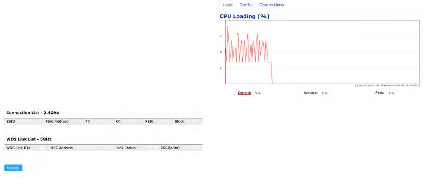
2.4 GHz/5 GHz Connection List
Click the connection link under the Overview menu displays
the connection list of clients associated to the AP’s 2.4
GHz/5 GHz, along with the MAC addresses and signal
strength for each client. Clicking Refresh updates the
client list.
Note: Only applicable in Access Point and WDS AP
modes.
2.4 GHz/5 GHz WDS Link List
Click the connection link under the Overview menu. This
pagedisplaysthecurrentstatusoftheWDSlink,including
WDSLinkID,MACAddress,LinkStatusandRSSI.
Note: Only applicable in WDS AP and WDS Bridge modes.
Realtime
TheRealtimesectioncontainsthefollowingoptions:
CPU Loading: 3 minutes CPU loading percentage
information,itdisplayscurrentloading,averageloading
and peak loading status. Left bar is loading percentage;
button is time tracing. Interval is every 3 seconds
Connections Realtime
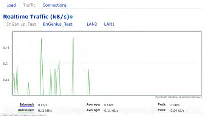
42
Trafc Loading: 2.4GHz and 5GHz and Ethernet port
inboundandoutboundtrafcbycurrent,averageand
peak time.
Realtime Connection (Pkts): Overview on current
activenetworkconnections.It displaysUDPand TCP
packetsinformationandotherconnectionstatus.UDP
connections curve is in blue; TCP connection curve is
in green; others curve is in red. Below of chart shows
connections source and destination.
43
Chapter 6
Network
44
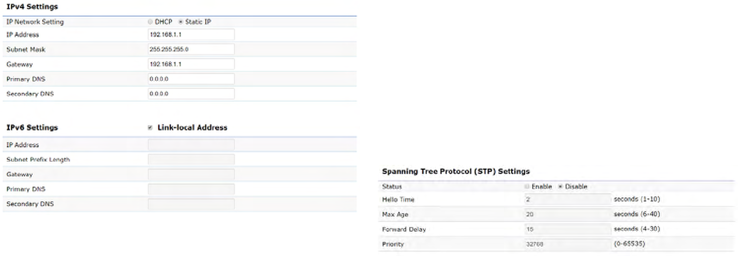
IPv4/IPv6 Settings
This page allows you to modify the device’s IP settings.
IP Network Settings: Select whether the device IP address
willuseastaticIPaddressspeciedintheIPaddresseld
or be obtained automatically when the device connects to
a DHCP server.
IP Address: The IP address of this device.
Subnet Mask: The IP Subnet mask of this device.
Gateway: The Default Gateway of this device. Leave it
blank if you are unsure of this setting.
Primary/Secondary DNS: The primary/secondary DNS
address for this device.
Save: Click Savetoconrmthechanges.
Spanning Tree Protocol (STP) Settings
This page allows you to modify the Spanning Tree settings.
Enabling the Spanning Tree protocol will prevent network
loops in your LAN network.
Spanning Tree Status:EnablesorDisablestheSpanning
Tree function. Default is Disable.
Hello Time: Species Bridge Hello Time in seconds. This
value determines how often the device sends handshake
packets to communicate information about the topology
throughout the entire Bridged Local Area Network.
Max Age: SpeciesBridgeMaxAgeinseconds.Ifanother
Basic
45
bridge in the spanning tree does not send a hello packet for
alongperiodoftime,itisassumedtobeinactive.
Forward Delay:SpeciesBridgeForwardDelayinseconds.
Forwarding delay time is the time spent in each of the
Listening and Learning states before the Forwarding state
is entered. This delay is provided so that when a new bridge
comesontoabusynetwork,itanalyzesdatatrafcbefore
participating in the network.
Priority: SpeciesthePriorityNumber.Asmallernumber
has a greater priority than a larger number.
Save: Click Savetoconrmthechanges.

46
Chapter 7
2.4 GHz & 5 GHz
Wireless
47
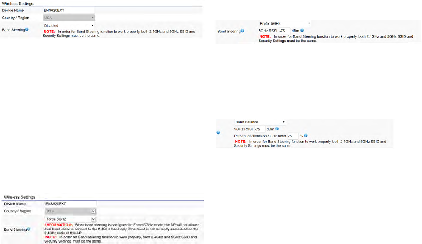
Wireless Settings
Device Name: Enter a name for the device. The name you
type appears in SNMP management. This name is not the
SSID and is not broadcast to other devices.
Band Steering (Avaiable on ENS620EXT): Enable Band
Steering to send 802.11n clients to the 5 GHz band,
where802.11b/gclientscannotgo,andleave802.11b/g
clients in 2.4GHz to operate at their slower rates. Before
implementingthisfeature,wesuggestyoutoassurethe
both2.4GHzand5GHzSSID,aswelllassecuritysettings
must be the same. EnGenius Band Steering supports
followingadvancedsettings,
*Force 5GHz:WhenbandsteeringisconguredtoForce
5GHz mode, the AP will not dual band capable client
devices to network to the 2.4GHz band only if the client
devices are not currently associated on 2.4GHz radio in
this AP.
*Prefer 5GHz:WhenbandsteeringisconguredtoPrefer
5GHz mode, the AP will steer dual band capable client
devices to 5GHz radio when the RSSI value of these client
devices on 5GHz radio is more than set one. The allowed
RSSI value for default setting is -75dBm.
*Band Balance: When band steering is congured to
BandBalancemode,theAPwillsteerdualbandcapable
client devices to 5GHz when the RSSI value of these client
devices on 5GHz radio is more than set one. To evenly
allocateRFresourceontheboth2.4GHzand5GHzradios,
users also can set the portion of client devices on 5GHz
radio to assure smoothly connection. The default value of
the5GHzradiois75%.
Save: Click Savetoconrmthechanges.
Wireless
48
This page displays the current status of the Wireless
settings of this AP.
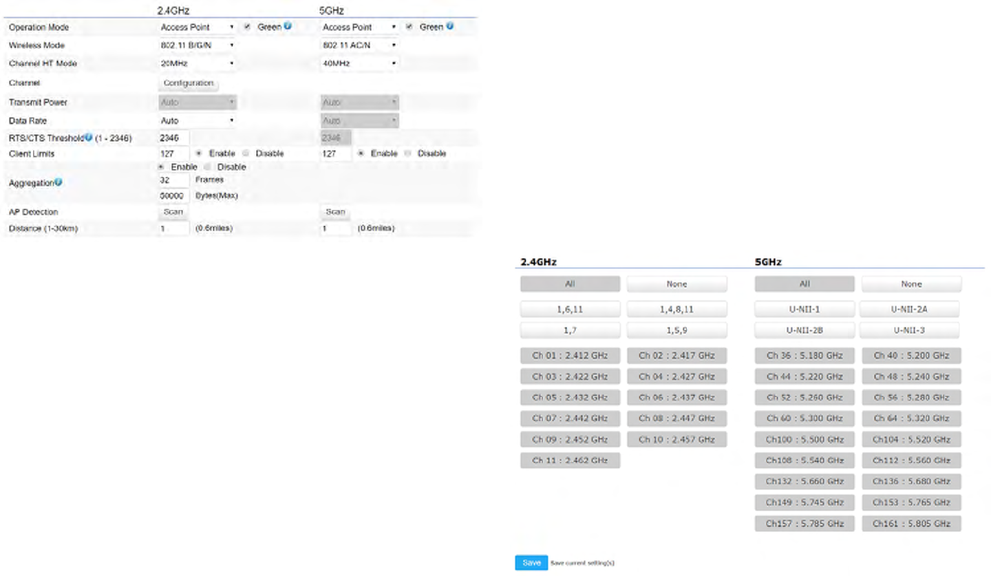
2.4 GHz/5 GHz Wireless Network
Operation Mode: Scrow down this list to select operation
modes for implementing on this radio. The default operation
mode is Access Point on base stations and Access Points
and is Client BridgeonClientPremiseEquipements(CPE).
Meanwhile, EnGenius outdoor devices also support WDS
modes for peer to peer or peer to multi-peer connections.
Wireless Mode: Scrow down this list to select wireless
broadcasting standard on 2.4GHz and 5GHz frequency
bands.
Channel HT Mode: Scrow down this list to select bandwidth
for operating under a frequency band. The default channel
bandwidth is 20 MHz on 2.4GHz frequency radio and 40
MHz on 5GHz frequency radio. Considering the different
applications, users can decide to implement a channel
bandwidthtofulllrealapplications.Thelargerthechannel,
the greater the transmission quality and speed.
Transmit Power (Tx Power):DefaultTxpowerisAuto
to obey regulartory power of each country.
Channel: Click Configuration button to open a new
windows to configure channels for performing wireless
service.
49
*Default conguration: Default setting of channel
selection is “All” to perform auto channel on the exist
channel list.
*None:Click“None”todisablethesettingonthisradio.
This radio is disabled.
*Group Conguration:Clickspecicgroupsof channels
forperformingautochannelfunction.Forexample,users
canclickU-NII-1andU-NII-3toperformautochannelon
these bands; the mechanism of this AP will select the
relatively optimal channel to peform wireless service.
Data Rate: Select a data rate from the drop-down list. The
data rate affects throughput of data in the AP. Select the
best balance for you and your network but note that the
lower the data rate, the lower the throughput, though
transmission distance is also lowered.
RTS/CTS Threshold:Speciesthethresholdpackagesize
for RTC/CTS. A small number causes RTS/CTS packets to be
sent more often and consumes more bandwidth.
Client Limits: Limits the total number of clients on this radio.
Oncesettingtheceilingofclientnumbers,themaximum
assocaited client devices will be restricted at this number.
Aggregation: Integrate multiple data packets into one
packet to deliver to client devices. This option reduces the
numberofpackets,butalsoincreasespacketsizes.
AP Detection: AP Detection can select the best channel to
use by scanning nearby areas for Access Points.
Distance: Species the distance between Access Points
and client devices. The proper setting for this parameter
may assist Access Points to avoid the improper operation
whentransmittingdataunderaledapplication.
Save: Click SavetoconrmthechangesorCancel to cancel
and return to previous settings.
50
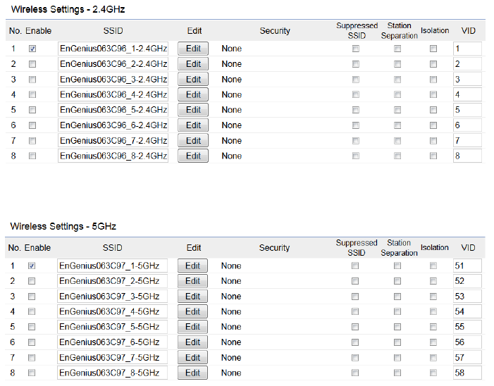
2.4 GHz/5 GHz SSID Prole
Current Prole: You can congure up to sixteen (16)
different SSIDs (eight (8) per band). If multiple client
deviceswillbeaccessingthenetwork,youcanarrangethe
devices into SSID groups. Click Edittoconguretheprole
andcheckwhetheryouwanttoenableextraSSID.
Enable: ClickthischeckboxtoenablethisSSIDinterface.
ThedefaultSSIDsareenableonthebothrst2.4GHzand
5GHz SSID.
SSID:SpeciestheSSIDforthecurrentprole.
Hidden SSID: Check this option to hide the SSID from clients.
Ifchecked,theSSIDwillnotappearinthesitesurvey.
Client Isolation: Click the appropriate radio button to enable
this function for allowing or preventing communication
between client devices.
VID:SpeciestheVLANtagforeachprole.Ifyournetowrk
includesVLANs,youcanspecifyaVLANIDforpacketspass
through the Access Point with a tag.
Wireless Security: See the Wireless Security section.
VLAN Isolation: Restrict clients communicating with
different VIDs by selecting the radio button.
L2 Isolation: Enable this function prevenet client devices
to communicate on the both WLAN and LAN.
Save: Click Save to accept the changes.
51
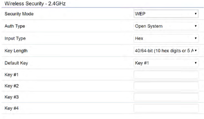
Wireless Security
TheWirelessSecuritysectionletsyouconguretheAP’s
security modes
Secuirty Mode: Including WEP, WPA-PSK, WPA2-PSK,
WPA-PSKMixed,WPA,WPA2,andWPAMixed.Westrongly
recommendyoutouseWPA2-PSKmode.
* Setting of WEP mode:
Auth Type: Select Open System or Shared Key.
Input Type:
ASCII:RegularText(recommended)
HexadecimalNumbers(Foradvancedusers)
Key Length: Select the desired option and ensure that
wirelessclientsusethesamesetting.Yourchoicesare64,
128,and152-bitpasswordlengths.
Default Key:Selectthe Keyyou wishtobe thedefault.
Transmitted data is ALWAYS encrypted using the Default
Key;theotherKeysarefordecryptiononly.Youmustenter
aKeyValuefortheDefaultKey.
Encryption Key Number:EntertheKeyValueorvalues
you wish to use. Only the Key selected as Default is
required. The others are optional.
52
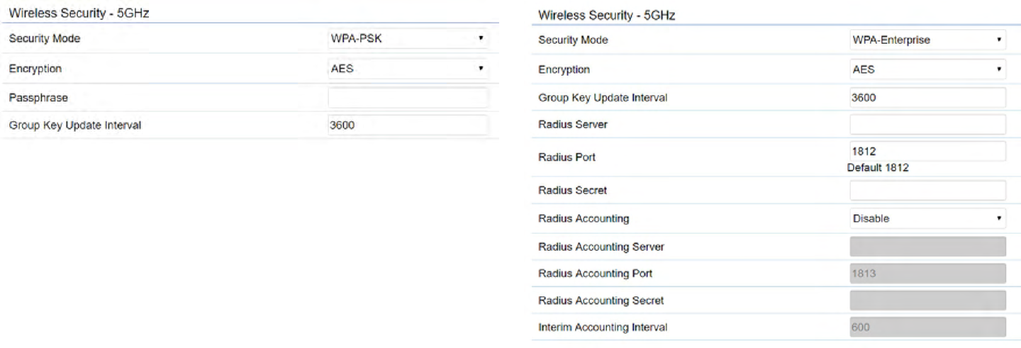
* Setting of WPA-PSK, WPA2-PSK and WPA-PSK Mixed
(Pre-Shared Key):
Encryption:YoumayselectAES,TKIPorBoth(TKIP+AES)
to be the encryption type you would like. Please ensure
that your wireless clients use the same settings.
Passphrase: Wireless clients must use the same Key to
associatethedevice.IfusingASCIIformat,theKeymust
befrom8to63charactersinlength.IfusingHEXformat,
theKeymustbe64HEXcharactersinlength.
Group Key Update Interval: Species how often, in
seconds,theGroupKeychanges.Thedefaultvalueis3600.
*
* Setting of WPA-Enterprise & WPA2-Enterprise (Pre-
Shared Key):
Encryption: Select the WPA encryption type you would like.
Please ensure that your wireless clients use the same settings.
Radius Server: Enter the IP address of the Radius server.
Radius Port: Enter the port number used for connections
to the Radius server.
53
Radius Secret: Enter the secret required to connect to the
Radius server.
Radius Accounting: Enable or disable accounting feature.
Radius Accounting Server: Enter the IP address of the
Radius accounting server.
Radius Accounting Port Enter the port number used for
connections to the Radius accounting server.
Radius Accounting Secret: Enter the secret required to
connect to the Radius accounting server.
Interim Accounting Interval: Species how often, in
seconds,theaccountingdatasends.
Note: 802.11n does not allow WEP/WPA-PSK TKIP/
WPA2-PSK TKIP security mode. The connection mode
willautomaticallychangefrom802.11nto802.11g.
54
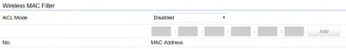
Wireless MAC Filtering
Wireless MAC Filtering is used to allow or deny network
access to wireless clients (computers, tablet PCs, NAS,
smartphones,etc.)accordingtotheirMACaddresses.You
can manually add a MAC address to restrict permission to
access this AP. The default setting is: Disable Wireless
MAC Filter.
Note: Only applicable in Access Point and WDS AP
modes.
ACL Mode: Determines whether network access is granted
or denied to clients whose MAC addresses appear in the
MACaddresstableonthispage.Yourchoicesare:Disabled,
DenyMACinthelist,orAllowMACinthelist.
MAC Address: Enter the MAC address of the wireless client.
Add: Click Add to add the MAC address to the MAC address
table.
Delete: Delete the selected entries.
Save: Click Save to apply the changes.
55
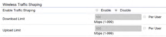
Wireless Advanced
Wireless Trafc Shaping
Trafc shaping regulates the ow of packets leaving an
interfacetodeliverimprovedQualityofService.
Enable Trafc Shaping:Defaultisdisable.Youmaycheck
thisoptiontoenableWirelessTrafcShapingperSSID.
Download Limit: Speciesthewirelesstransmissionspeed
used for downloading.
Upload Limit: Species the wireless transmission speed
used for uploading.
Per User: Check this option to enable wireless trafc
shaping per user function. This function allow users to limit
themaximumdownload/uploadbandwidthforeachclient
devices on this SSID.
Save: Click Savetoconrmthechanges.

56
Fast Roaming
Enable the function to serve mobile client devices that roam
from Access Point to Access Point. Some applications running
on Client devices require fast re-association when they roam
to a different Access Point
Please enter the settings of the SSID and initialize the Security
modetoWPAenterprise,aswellastosettheRadiusServer
rstly.UserscanenabletheFastRoamingandimplementthe
advanced search.
Please also set the same enterprise Encryption under
the same SSID on other Access Points and enable the
Fast Roaming. When the conguration is realized on
different Access Point, the mobile client devices can run
the voice service and require seamless roaming to prevent
delay in conversation from Access Point to Access Point.
Enable Fast Roaming: Enable or disable fast roaming
feature.
Enable Advanced Search: Enable or disable advanced
search feature.
57
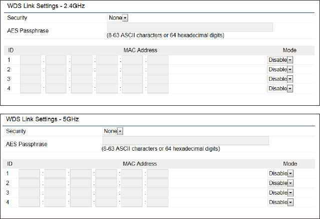
WDS Link Settings
UsingtheWDS(WirelessDistributionSystem)featurewill
allow a network administrator or installer to connect to
Access Points wirelessly. Doing so will extend the wired
infrastructure to locations where cabling is not possible or
inefcienttoimplement.
Note: Compatibility between different brands and
models of Access Points is not guaranteed. It is
recommended that the WDS network be created using
thesamemodelsformaximumcompatibility.
Also note: All Access Points in the WDS network need
to use the same Channel and Security settings.
TocreateaWDSnetwork,pleaseentertheMACaddresses
of the Access Points that you want included in the WDS.
TherecanbeamaximumoffourAccessPoints.
Note: Only applicable in WDS AP and WDS Bridge modes.
2.4 GHz/5 GHz WDS Link Settings
Security: Select None or AES from the drop-down list.
AES Passphrase: Enterthe KeyValues youwish touse.
OtherAccessPointsmustusethesameKeytoestablisha
WDS link.
MAC Address: Enter the Access Point’s MAC address to
whereyouwanttoextendthewirelessarea.
Mode:Selecttodisableorenablefromthedrop-downlist.
Save: Click Save toconrmthechanges.
58
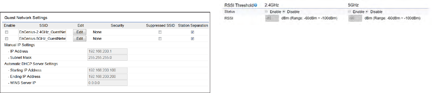
Guest Network Settings
Adding a guest network allows visitors to use the Internet
without giving out your ofce or company wireless
security key. You can add a guest network to each
wireless network in the 2.4 GHz b/g/n and 5 GHz ac/a/n
frequencies.
SSID:SpeciestheSSIDforthecurrentprole.
Suppressed SSID: Check this option to hide the SSID from
clients.Ifchecked,theSSIDwillnotappearinthesitesurvey.
Station Separation: Click the appropriate radio button to
allow or prevent communication between client devices.
IP Address: The IP Address of this device.
Subnet Mask: The IP Subnet mask of this device.
Starting IP Address: TherstIPAddressintherangeof
the addresses by the DHCP server.
Ending IP Address: The last IP Address in the range of
addresses assigned by the DHCP server.
RSSI Threshold (AP mode Only)
RSSI Threshold: Enable the RSSI Threshold feature by
ensuring that each client is served by at least one Access
Point at any time. Access Points continuously monitor
the connectivity quality of any client in their range and
efcientlysharethisinformationwithotherAccessPoints
in the vincinity of that client to coordinate which of them
should serve the client best.
RSSI: Enter the RSSI (Received Signal Strength Index) in
order to determine the handover procedure which the
current wireless link will terminate. RSSI is an indication of
thepowerlevelbeingreceivedbytheantenna.Therefore,
thehighertheRSSInumber,thestrongerthesignal.

59
Chapter8
Management
60
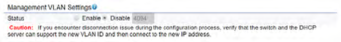
Management VLAN Settings
This page allows you to assign a VLAN tag to packets sent
over the network. A VLAN is a group of computers on a
networkwhosesoftwarehasbeenconguredsothatthey
behave as if they were on a separate Local Area Network
(LAN). Computers on VLAN do not have to be physically
locatednexttooneanotherontheLAN.
Note: Only applicable in Access Point and WDS AP
modes.
Management VLAN:IfyournetworkincludesVLANs,you
can enable Management VLAN ID for packets passing
through the Access Point with a tag.
Save: Click SavetoconrmthechangesorCancel to cancel
and return to previous settings.
Note: IfyoureconguretheManagementVLANID,you
may lose your connection to this AP. Verify that the
DHCP server supports the recongured VLAN ID and
then reconnect to this AP using the new IP address.
61
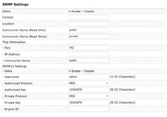
SNMP Settings
ThispageallowsyoutoassigntheContactDetails,Location,
CommunityName, andTrap Settingsfor aSimple Network
Management Protocol (SNMP). SNMP is a networking
management protocol used to monitor network attached
devices.SNMPallowsmessages(calledprotocoldataunits)
tobesenttovariouspartsofthenetwork.Upon receiving
these messages, SNMP compatible devices (called agents)
returns the data stored in their Management Information
Bases.
SNMP Enable/Disable:EnablesordisablestheSNMP
feature.
Contact: Speciesthecontactdetailsofthedevice.
Location: Speciesthelocationofthedevice.
Community Name (Read Only): Speciesthepassword
for the SNMP community for read only access.
Community Name (Read/Write):Speciesthepassword
for the SNMP community with read/write access.
Trap Destination Address:SpeciestheIPaddressofthe
computer that will receive the SNMP traps.
Trap Destination Community Name: Speciesthe
password for the SNMP trap community.
SNMPv3: Enables or disables the SNMPv3 feature.
User Name:SpeciestheusernameforSNMPv3.
Auth Protocol:Selectstheauthenticationprotocoltype:
MDS or SHA.
Auth Key: Speciestheauthenticationkey.
Priv Protocol:Selectstheprivacyprotocoltype:DES.
Priv Key: Speciestheprivacykeyforprivacy.
Advanced Settings
62
Engine ID: SpeciestheengineIDforSNMPv3.
Apply Save: Click Apply Save to apply the changes.
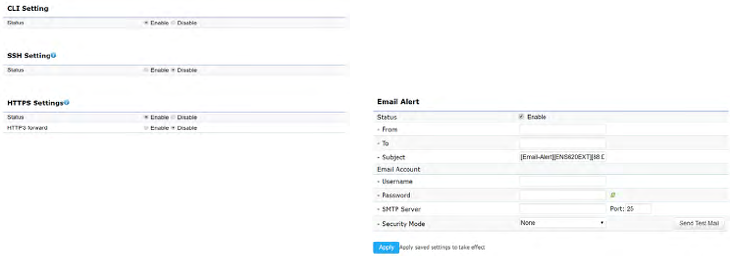
CLI Settings
CLI:TheCommandLineInterface(CLI)allowsyoutotype
commands instead of choosing them from a menu or
selecting an icon.
SSH:EnableSecureShell(SSH)tomakesecure,encrypted
connections in the network. Secure Shell is a network
protocolthatallowsdatatobeexchangedusingasecure
channel between two network devices.
HTTPS: Enable HTTPS to transfer and display web content
securely.TheHypertextTransferProtocoloverSSL(Secure
SocketLayer)isaTCP/IPprotocolusedbywebserversto
transfer and display web content securely.
Email Alert
You can use the Email Alert feature to send messages
to the congured email address when particular system
events occur.
Note:DoNOT use your personal email address as it can
unnecessarilyexposeyourpersonalemaillogincredentials.
Useaseparateemailaccountmadeforthisfeatureinstead
Status: Enable this function for further settings.
From: Enter the email address to show the sender of the
email.
To: Enter the address to receive email alerts.
Subject: Enterthetexttoappearintheemailsubjectline.
63
Username: Enter the username for the email account that
will be used to send emails.
Password: Enter the password for the email account that
will be used to send emails.
SMTP Server: Enter the IP address or hostname of the
outgoing SMTP server.
Port: Enter the SMTP port number to use for outbound
emails.
64
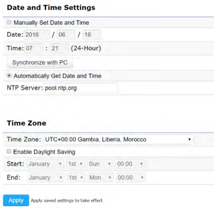
Time Setting
This page allows you to set the internal clock of the AP. Manually Set Date and Time: Manually specify the
date and time.
Synchorize with PC:Clickthisbuttontosynchorize
Date and time of this AP with the PC.
Automatically Get Date and Time: Select
Automatically Get Date and Time and check whether
you wish to enter the IP address of an NTP server or
use the default NTP server to have the internal clock
set automatically.
Time Zone: Choose a time zone to implement the
service for this AP.
Enable Daylight Saving:Checkwhetherdaylight
savings applies to your area.
Start:Selecttheday,month,andtimewhendaylight
savings time starts.
Enable Daylight Saving:Selecttheday,month,andtime
when daylight savings times ends.
Time Zone
65
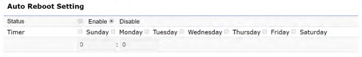
Auto Reboot Settings
You can specify how often you wish to reboot the AP.
Auto Reboot Setting: Enables or disables the Auto
Reboot function.
Timer:Selectthedayandenterthetimeyouwouldlike
to reboot automatically.
Save:ClickSave to apply the changes.
66
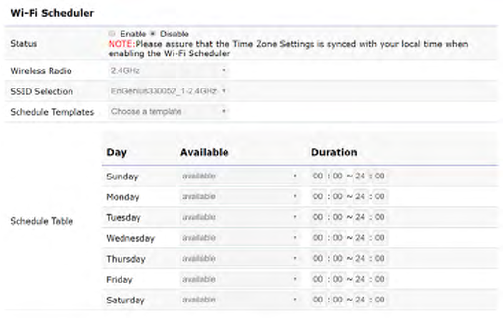
Wi-Fi Scheduler
The Wi-Fi Scheduler can be created for use in enforcing
rules. For example, if you wish to restrict web access to
Mon-Fri from 3pm to 8pm, you could create a schedule
selectingMon,Tue,Wed,ThuandFriwhileenteringaStart
timeof3pmandEndTimeof8pmtolimitaccesstothese
times.
Status: Enables or disables the Wi-Fi scheduler function.
Wireless Radio: Select 2.4 GHz or 5 GHz from the drop-
down list for the preferred band type.
SSID Selection: Select a SSID from the drop-down list.
Schedule Templates: Select a schedule template from the
drop-down list.
Day(s): Placeacheckmarkintheboxesforthedesireddays
or select the All Week radio button to select all seven days
of the week.
Duration:TheStartTimeisenteredintwoelds.Therst
boxisforhoursandthesecondboxisforminutes.TheEnd
Time is entered in the same format as the Start time.
67
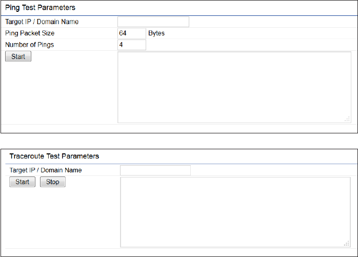
Ping Test Parameters
This page allows you to analyze the connection quality
of the AP and trace the routing table to a target in the
network.
Target IP: Enter the IP address you would like to search.
Ping Packet Size: Enter the packet size of each ping.
Number of Pings: Enter the number of times you wish to
ping.
Start Ping: Click Start Ping to begin pinging the target
device(viaIP).
Traceroute Target: Enter the IP address or domain name
you wish to trace.
Start Traceroute: Click Start Traceroute to begin the trace
route operation.
Tools
68
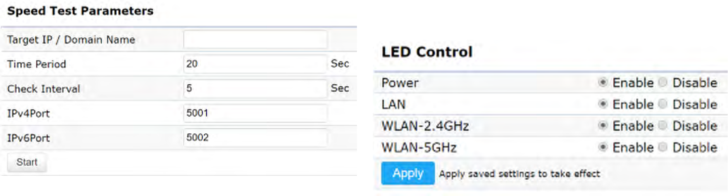
Speed Test Parameters / LED Control
This page allows you to implement speed test to realize
thethroughputofatargetDUT.
Target IP / Domain Name: Enter an IP address or domain
name you wish to impelement a speed test for realizing
the variance on wireless speed.
Time Period: Enter the time in seconds that you would like
the test to implement for and in how many intervals.
IPv4/IPv6 Port: This Access Points uses IPv4 5001 and
IPv6 5002 port for the speed test.
Start:Clickstarttoimplementspeedtest.
LED Control
ControlLEDon/offforPower,LANinterface,or2.4GHz/5
GHz WLAN interface.
Power: Enables or disables the Power LED indicator.
LAN: Enables or disables the LAN LED indicator.
WLAN-2.4 GHz: Enables or disables the WLAN-2.4 GHz LED
indicator.
WLAN-5 GHz: Enables or disables the WLAN-5 GHz LED
indicator.
69
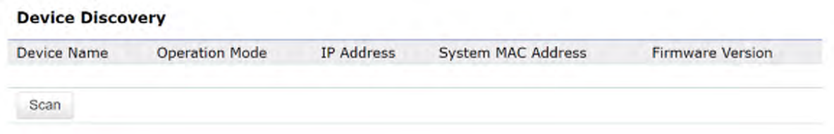
Device Discovery
This page allows you to discover devices from network
forOperationMode,IPAddress,SystemMACAddressand
Firmware version.
70
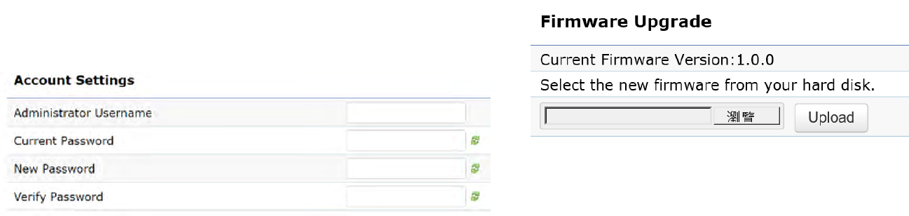
This page allows you to change the AP username and
password. By default, the username is: admin and the
passwordis:admin. The password can contain from 0 to
12 alphanumeric characters and is case sensitive.
Account Settings
Administrator Username: Enter a new username for
loggingintotheNewNameentrybox.
Current Password: Enter the old password for logging in
totheOldPasswordentrybox.
New Password: Enter the new password for logging in to
theNewPasswordentrybox.
Verify Password: Re-enter the new password in the
ConrmPasswordentryboxforconrmation.
Apply: Click Apply to apply the changes.
Firmware Upgrade
This page allows you to upgrade the firmware of the
AP.
To Perform the Firmware Upgrade:
1. Click the Choose File buttonandnavigate theOSle
systemtothelocationoftheupgradele.
2. Selecttheupgradele.Thenameofthelewillappear
intheUpgradeFileeld.
3. Click the Upload button to commence the rmware
upgrade.
Note: The device is unavailable during the Firmware
upgrade process and must restart when the upgrade is
completed. Any connections to or through the device
will be lost.
Account Firmware
71
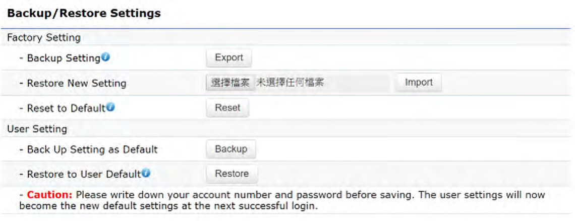
Backup/Restore
This page allows you to save the current device
configurations. When you save your configurations,
you also can reload the saved configurations into the
device through the Restore Saved Settings from a file
section.Ifextremeproblemsoccur,orifyouhaveset
theAPincorrectly,youcanusetheReset button in the
Revert to Factory Default Settings section to restore
all the configurations of the AP to the original default
settings.
Backup Setting: Click Export to save the current
configured settings.
Restore New Setting: To restore settings that have
been previously backed up, click Browse, select the
file,andclickRestore.
Restore to Default: Click Reset button to restore the
AP to its factory default settings.

72
User Setting
The function allows you to backup the current device
configurations into the AP as the default value. If
extreme problems occur, or if you have set the AP
incorrectly,youcanpushtheResetbuttontorevertall
the configurations of the AP to the user default.
Back Up Setting as Default: Click Backup to backup
the user settings you would like to the device’s memory
for the default settings.
Restore to User Default:ClickRestore to restore user
settings to the factory standard settings.
Note1:Aftersettingthecurrentsettingsasthedefault,youshouldclicktheRestore to Default on the
web interface for reverting the settings into the factory default instead of pushing the reset button.
Note2: Please write down your account and password before saving. The user settings will now become
thenewdefaultsettingsatthenextsuccessfullogin.
73
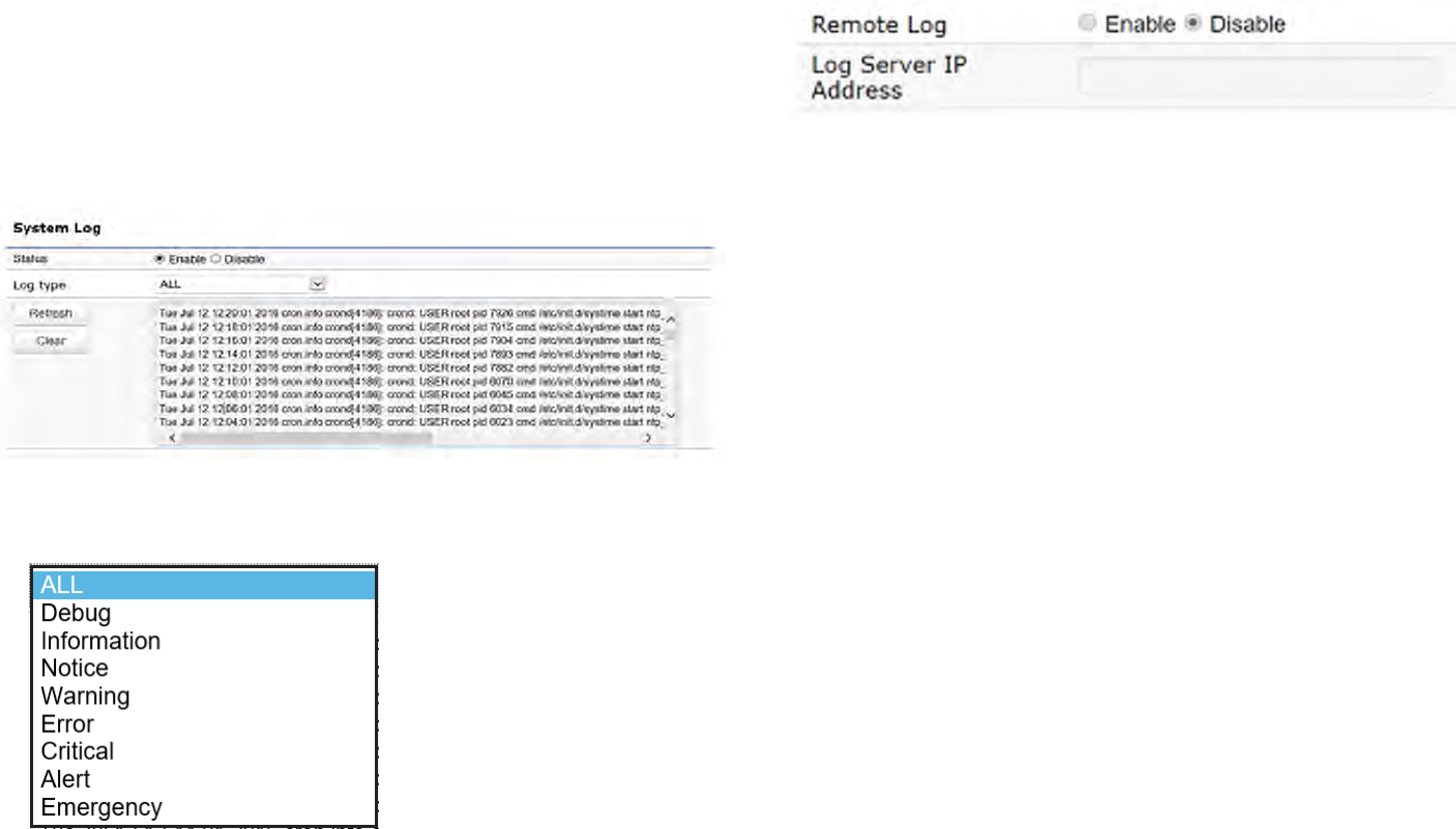
System Log
The AP automatically logs (records) events of possible
interest in its internal memory. To view the logged
information,clicktheLog link under the System Manager
menu. If there is not enough internal memory to log all
events, older events are deleted from the log. When
powereddownorrebooted,thelogwillbecleared.
Status:Enable/Disablethisfunction.
Log type: You may choose one of log types to display logs
in the following window. The default log types is All.
Remote Log
This page allows you to setup the Remote Log functions
for this AP.
Remote Log:Enable/Disablethisfunction.
Log Server IP Address: Enter the IP address of the log
server.
Apply: Click Apply to apply the changes.
Log
74
Logout
Logout: Click Logout in Management menu to logout.
Pleaseconrmagaintologoutthesystemornot.
Reset
In some circumstances, it may be required to force the
device to reboot. Click on Reset to reboot the AP.
Onceyouclick resetbutton,you willseethe optionsfor
reboot or restore this AP.
Rebootthedevice:Clickittorebootthisdevice.
RestoretoFactoryDefault:Clickittoresetthisdeviceto
factory default setting.
RestoretoUserDefault:Clickittoresetthisdeviceto
userdefaultsettings.Forrealizingthesettingmethod,
you may refer page 65 and page 66.

75
Appendix
76
Federal Communication Commission Interference Statement
This equipment has been tested and found to comply with the limits for a Class B digital device, pursuant to Part 15 of the FCC Rules. These limits are
designed to provide reasonable protection against harmful interference in a residential installation. This equipment generates, uses and can radiate
radio frequency energy and, if not installed and used in accordance with the instructions, may cause harmful interference to radio communications.
However, there is no guarantee that interference will not occur in a particular installation. If this equipment does cause harmful interference to radio
one of the following measures:
• Reorient or relocate the receiving antenna.
• Increase the separation between the equipment and receiver.
• Connect the equipment into an outlet on a circuit from that to which the receiver is connected.
• Consult the dealer or an experienced radio/TV technician for help
FCC Caution:
this equipment.
This device complies with Part 15 of the FCC Rules. Operation is subject to the following two conditions: (1) This device may not cause harmful
interference, and (2) this device must accept any interference received, including interference that may cause undesired operation.
This transmitter must not be co-located or operating in conjunction with any other antenna or transmitter.
IMPORTANT NOTE:
Radiation Exposure Statement
ENS620EXT: This equipment complies with FCC radiation exposure limits set forth for an uncontrolled environment. This equipment should be installed
and operated with minimum distance 21 cm between the radiator & your body.
ENS610EXT: This equipment complies with FCC radiation exposure limits set forth for an uncontrolled environment. This equipment should be installed
and operated with minimum distance 25 cm between the radiator & your body.
ENS500-AC/ENS500EXT-AC: This equipment complies with FCC radiation exposure limits set forth for an uncontrolled environment. This equipment
should be installed and operated with minimum distance 25 cm between the radiator & your body.
Appendix A - FCC Interference Statement
77
Europe – EU Declaration of Conformity
ThisdevicecomplieswiththeessentialrequirementsoftheR&TTEDirective1999/5/EC.Thefollowingtestmethodshavebeenappliedinorder
toprovepresumptionofconformitywiththeessentialrequirementsoftheR&TTEDirective1999/5/EC:
• EN60950-1
Safety of Information Technology Equipment
• EN50385
Generic standard to demonstrate the compliance of electronic and electrical apparatus with the basic restrictions related to human exposure
to electromagnetic elds (0 Hz - 300 GHz)
• EN300328
Electromagnetic compatibility and Radio spectrum Matters (ERM); Wideband Transmission systems; Data transmission equipment operating
in the 2,4 GHz ISM band and using spread spectrum modulation techniques; Harmonized EN covering essential requirements under article
3.2 of the R&TTE Directive
• EN301893
Broadband Radio Access Networks (BRAN); 5 GHz high performance RLAN; Harmonized EN covering essential requirements of article 3.2 of
the R&TTE Directive
• EN301489-1
Electromagnetic compatibility and Radio Spectrum Matters (ERM); ElectroMagnetic Compatibility (EMC) standard for radio equipment and
services; Part 1: Common technical requirements
• EN301489-17
Electromagnetic compatibility and Radio spectrum Matters (ERM); ElectroMagnetic Compatibility (EMC) standard for radio equipment and
services; Part 17: Specic conditions for 2,4 GHz wideband transmission systems and 5 GHz high performance RLAN equipment
Appendix B - CE Interference Statement

78
This device is a 5GHz wideband transmission system (transceiver), intended for use in all EU member states and EFTA countries, except in France
and Italy where restrictive use applies.
In Italy the end-user should apply for a license at the national spectrum authorities in order to obtain authorization to use the device for setting
upoutdoorradiolinksand/orforsupplyingpublicaccesstotelecommunicationsand/ornetworkservices.
This device may not be used for setting up outdoor radio links in France and in some areas the RF output power may be limited to 10 mW EIRP
in the frequency range of 2454 – 2483.5 MHz. For detailed information the end-user should contact the national spectrum authority in France.
Česky [Czech] [Jméno výrobce] tímto prohlašuje, že tento [typ zařízení] je ve shodě se základními požadavky a dalšími příslušnými
ustanoveními směrnice 1999/5/ES.
Dansk [Danish] Undertegnede [fabrikantens navn] erklærer herved, at følgende udstyr [udstyrets typebetegnelse] overholder de
væsentlige krav og øvrige relevante krav i direktiv 1999/5/EF.
Deutsch [German] Hiermit erklärt [Name des Herstellers], dass sich das Gerät [Gerätetyp] in Übereinstimmung mit den grundlegenden
Anforderungen und den übrigen einschlägigen Bestimmungen der Richtlinie 1999/5/EG befindet.
Eesti [Estonian] Käesolevaga kinnitab [tootja nimi = name of manufacturer] seadme [seadme tüüp = type of equipment] vastavust
direktiivi 1999/5/EÜ põhinõuetele ja nimetatud direktiivist tulenevatele teistele asjakohastele sätetele.
English Hereby, [name of manufacturer], declares that this [type of equipment] is in compliance with the essential requirements
and other relevant provisions of Directive 1999/5/EC.
Español [Spanish] Por medio de la presente [nombre del fabricante] declara que el [clase de equipo] cumple con los requisitos esenciales
y cualesquiera otras disposiciones aplicables o exigibles de la Directiva 1999/5/CE.
Ελληνική [Greek] ΜΕ ΤΗΝ ΠΑΡΟΥΣΑ [name of manufacturer] ΔΗΛΩΝΕΙ ΟΤΙ [type of equipment] ΣΥΜΜΟΡΦΩΝΕΤΑΙ ΠΡΟΣ ΤΙΣ ΟΥΣΙΩΔΕΙΣ
ΑΠΑΙΤΗΣΕΙΣ ΚΑΙ ΤΙΣ ΛΟΙΠΕΣ ΣΧΕΤΙΚΕΣ ΔΙΑΤΑΞΕΙΣ ΤΗΣ ΟΔΗΓΙΑΣ 1999/5/ΕΚ.

79
Français [French] Par la présente [nom du fabricant] déclare que l’appareil [type d’appareil] est conforme aux exigences essentielles et aux
autres dispositions pertinentes de la directive 1999/5/CE.
Italiano [Italian] Con la presente [nome del costruttore] dichiara che questo [tipo di apparecchio] è conforme ai requisiti essenziali ed alle
altre disposizioni pertinenti stabilite dalla direttiva 1999/5/CE.
Latviski [Latvian] Ar šo [name of manufacturer / izgatavotāja nosaukums] deklarē, ka [type of equipment / iekārtas tips] atbilst Direktīvas
1999/ 5/EK būtiskajām prasībām un citiem ar to saistītajiem noteikumiem.
Lietuvių [Lithuanian] Šiuo [manufacturer name] deklaruoja, kad šis [equipment type] atitinka esminius reikalavimus ir kitas 1999/5/EB
Direktyvos nuostatas.
Nederlands [Dutch] Hierbij verklaart [naam van de fabrikant] dat het toestel [type van toestel] in overeenstemming is met de essentiële eisen
en de andere relevante bepalingen van richtlijn 1999/5/EG.
Malti [Maltese] Hawnhekk, [isem tal-manifattur], jiddikjara li dan [il-mudel tal-prodott] jikkonforma mal-ħtiġijiet essenzjali u ma provvedimenti
oħrajn relevanti li hemm fid-Dirrettiva 1999/5/EC.
Magyar [Hungarian] Alulírott, [gyártó neve] nyilatkozom, hogy a [... típus] megfelel a vonatkozó alapvetõ követelményeknek és az 1999/5/EC
irányelv egyéb elõírásainak.
Polski [Polish] Niniejszym [nazwa producenta] oświadcza, że [nazwa wyrobu] jest zgodny z zasadniczymi wymogami oraz pozostałymi
stosownymi postanowieniami Dyrektywy 1999/5/EC.
Português [Portuguese] [Nome do fabricante] declara que este [tipo de equipamento] está conforme com os requisitos essenciais e outras
disposições da Directiva 1999/5/CE.
Slovensko [Slovenian] [Ime proizvajalca] izjavlja, da je ta [tip opreme] v skladu z bistvenimi zahtevami in ostalimi relevantnimi določili direktive
1999/5/ES.
Slovensky [Slovak] [Meno výrobcu] týmto vyhlasuje, že [typ zariadenia] spĺňa základné požiadavky a všetky príslušné ustanovenia Smernice
1999/5/ES.
Suomi [Finnish] [Valmistaja = manufacturer] vakuuttaa täten että [type of equipment = laitteen tyyppimerkintä] tyyppinen laite on
direktiivin 1999/5/EY oleellisten vaatimusten ja sitä koskevien direktiivin muiden ehtojen mukainen.
Svenska [Swedish] Härmed intygar [företag] att denna [utrustningstyp] står I överensstämmelse med de väsentliga egenskapskrav och
övriga relevanta bestämmelser som framgår av direktiv 1999/5/EG.

80
Appendix C - Professional Installation Instruction
Installation Personal
general user shall not attempt to install or change the setting.
Installation Location
The product shall be installed at a location where the radiating antenna can be kept 25cm from nearby person in normal operation condition to
meet regulatory RF exposure requirement.
External Antenna
Use only the antennas which have been approved by the applicant. The non-approved antenna(s) may produce unwanted spurious or excessive
RF transmitting power which may lead to the violation of FCC limit and is prohibited.
Installation Procedure
Please refer to user’s manual for the detail.
Warning:
rules. The violation of the rule could lead to serious federal penalty.