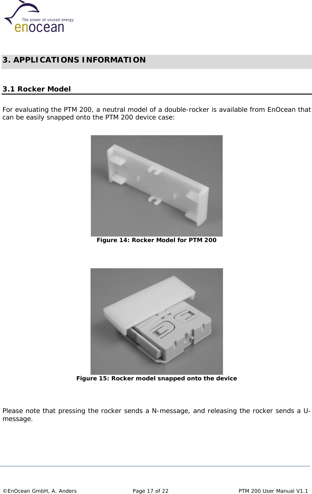
EnOcean PTM200 Wireless Switch User Manual PTM 200
EnOcean GmbH Wireless Switch PTM 200
UserManual.wiki
>
EnOcean
>
PTM200 User Manual
User Manual
Navigation menu
Upload a User Manual
Namespaces
Wiki Guide
HTML
PDF
Info
Views
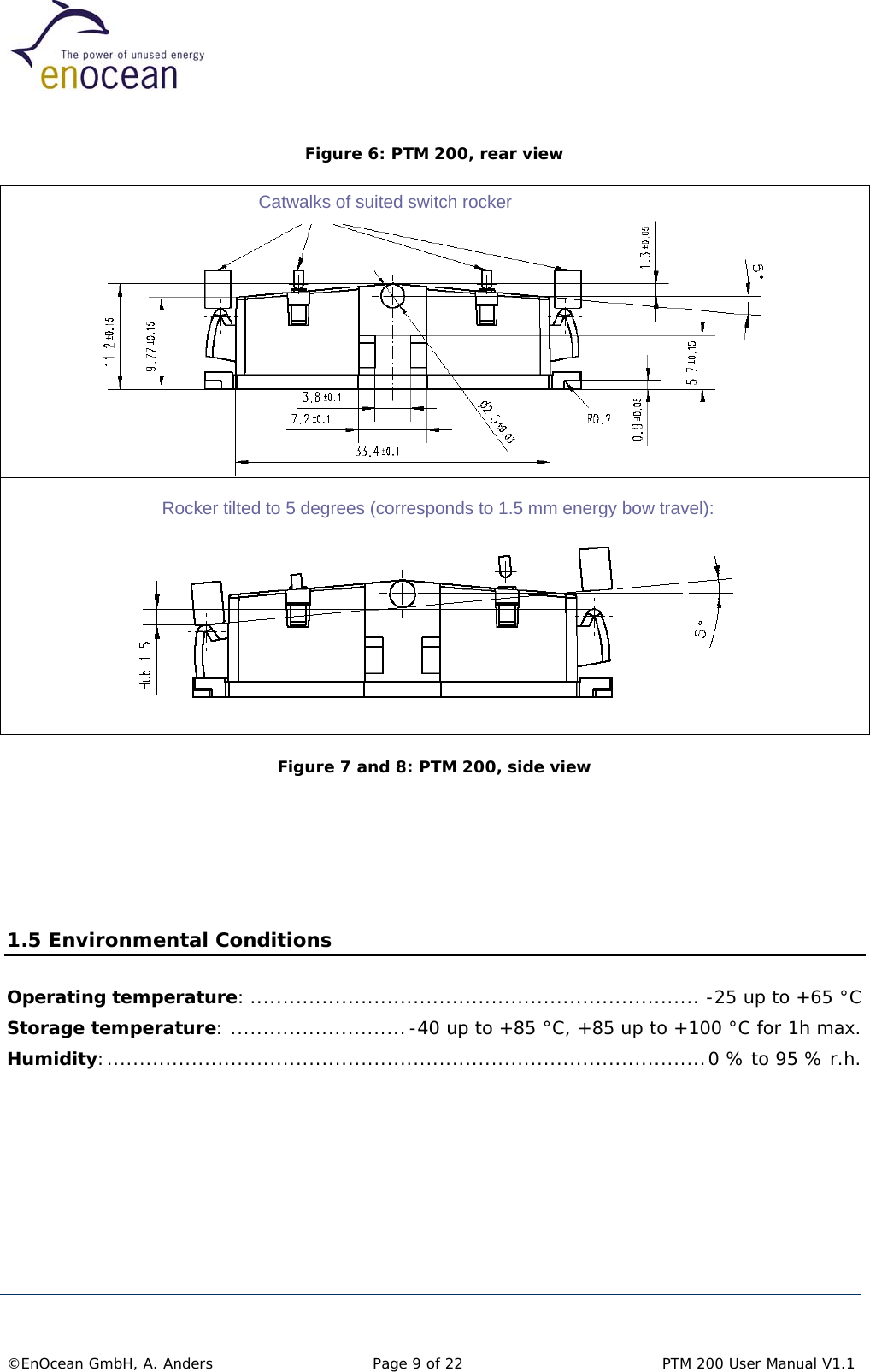
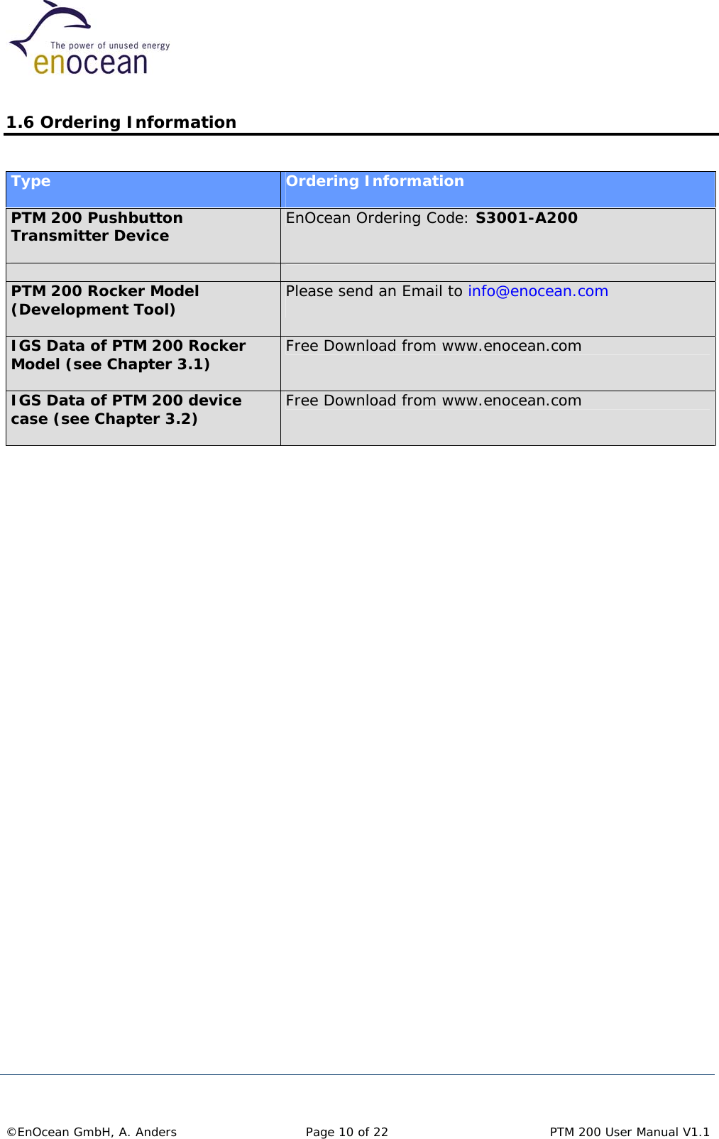
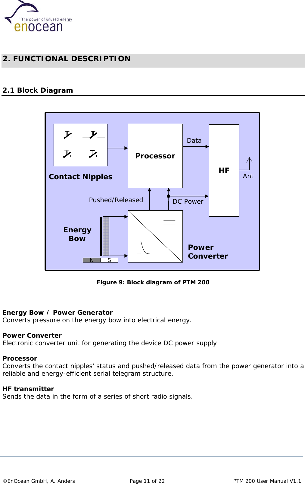
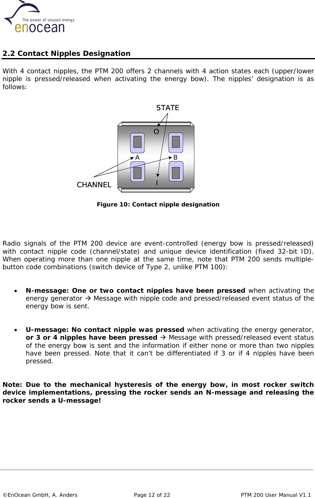
User Manual
Discussion / Help
Navigation