EnOcean PTM330U 902.875MHz transmitter User Manual users manual
EnOcean GmbH 902.875MHz transmitter users manual
UserManual.wiki
>
EnOcean
>
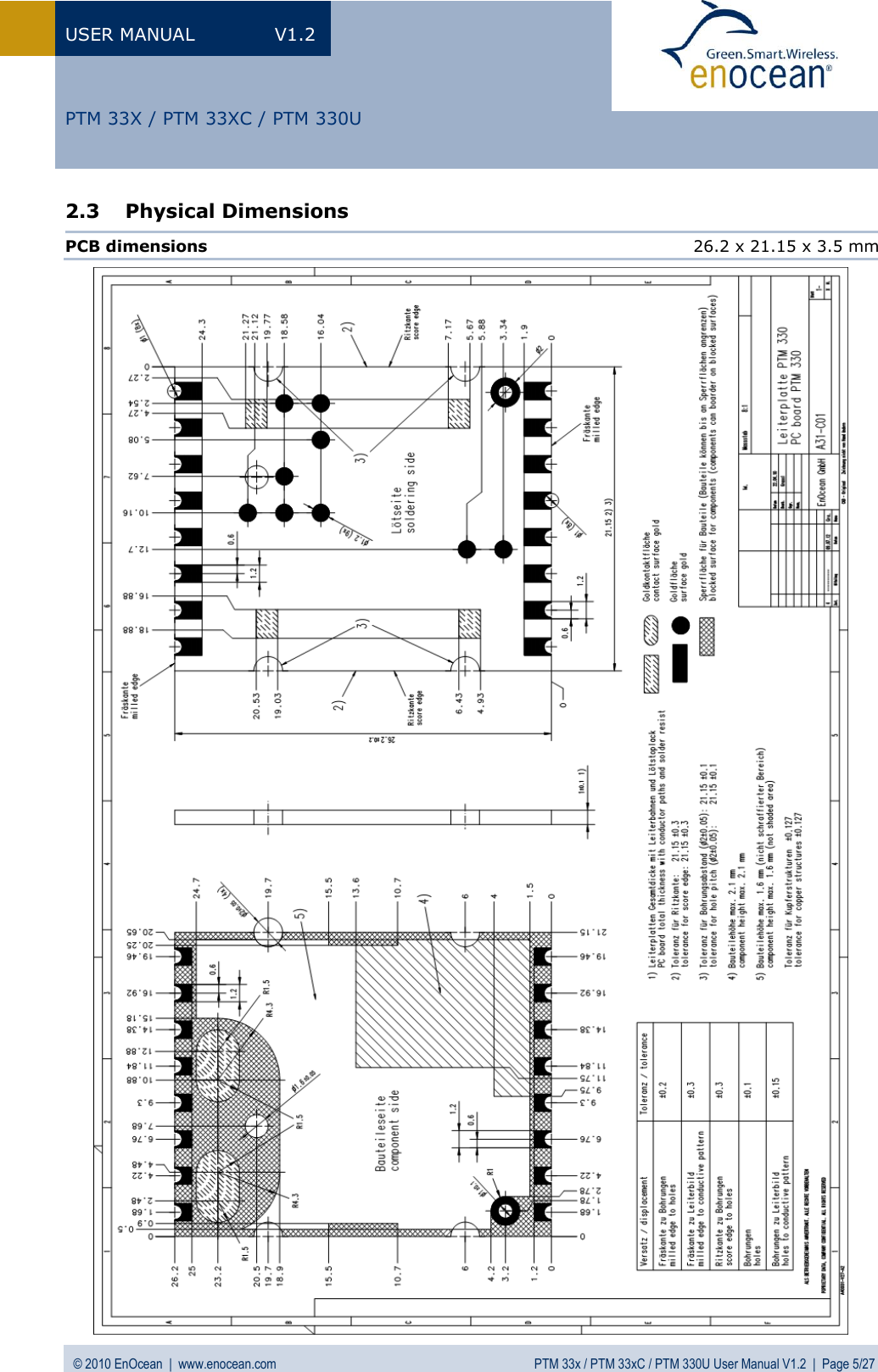
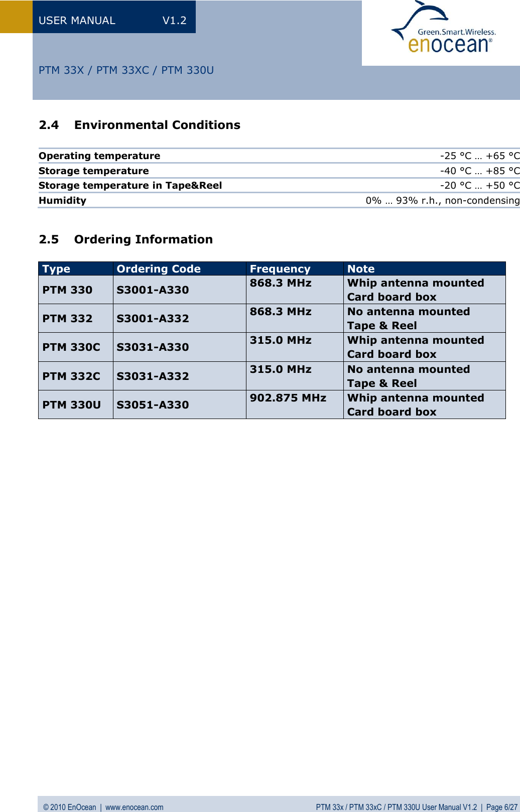
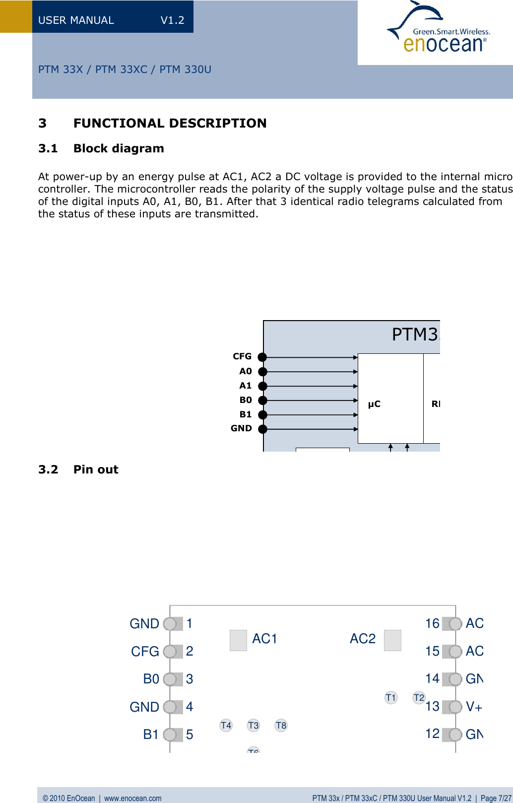
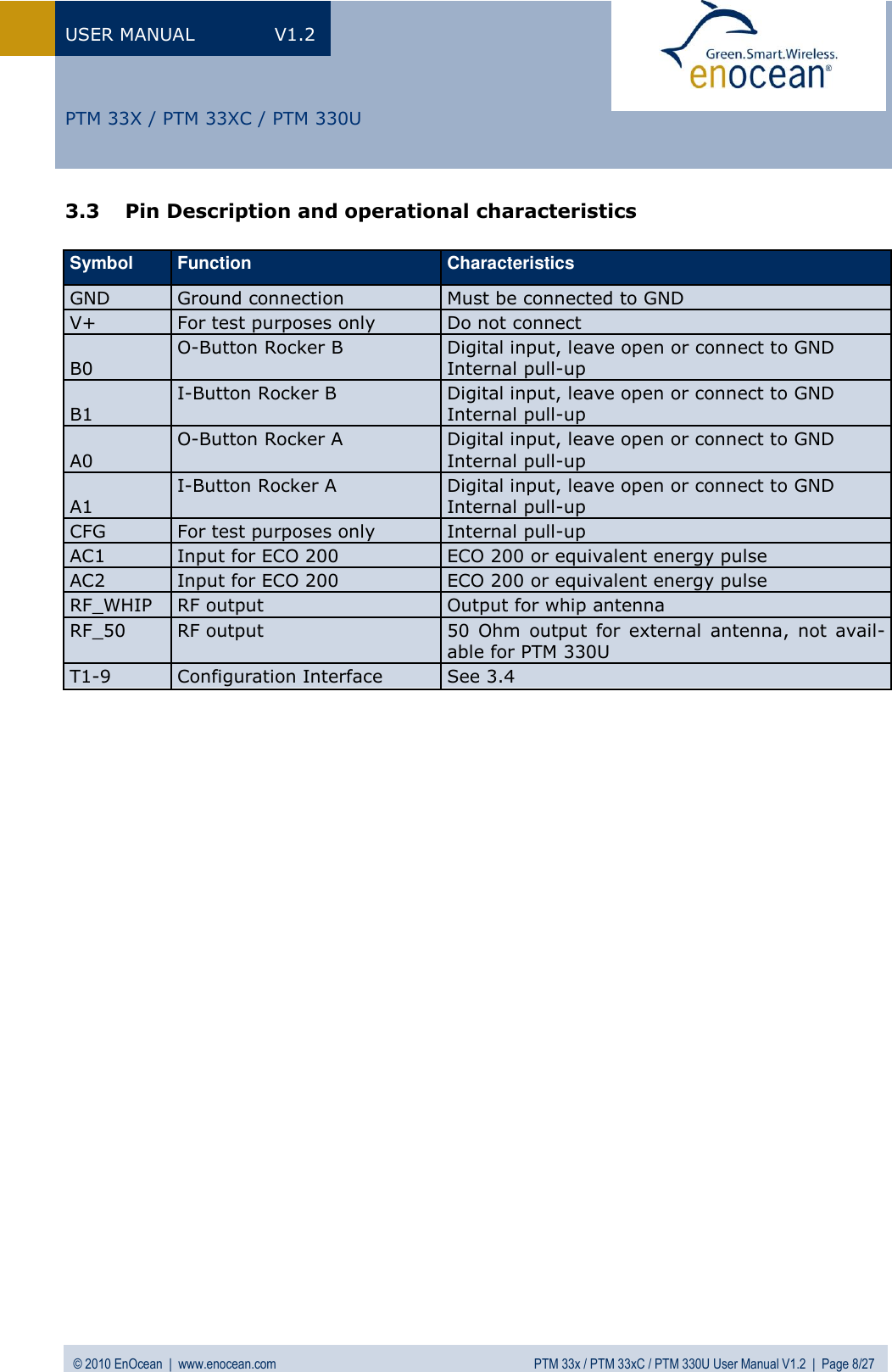
PTM330U User Manual
users manual
Navigation menu
Upload a User Manual
Namespaces
Wiki Guide
HTML
PDF
Info
Views
User Manual
Discussion / Help
Navigation