EnOcean PTM33XC 315 MHz Transmitter User Manual PTM 330 V0 80wip
EnOcean GmbH 315 MHz Transmitter PTM 330 V0 80wip
EnOcean >
Users Manual

USER MANUA
L
V0.8
EnOcean GmbH
Kolpingring 18a
82041 Oberhaching
Germany
Phone +49.89.67 34 689-0
Fax +49.89.67 34 689-50
info@enocean.com
www.enocean.com
Subject to modifications
PTM 33x / 33xC User Manual V0.8
May 10, 2010 10:54 AM
Page 1/20
Patent protected:
WO98/36395, DE 100 25 561, DE 101 50 128,
WO 2004/051591, DE 103 01 678 A1, DE 10309334,
WO 04/109236, WO 05/096482, WO 02/095707,
US 6,747,573, US 7,019,241
Observe precautions! Electrostatic sensitive devices!
Transmitter Module
PTM 33x / 33xC
May 4, 2010

USER MANUA
L
V0.8
© 2009 EnOcean | www.enocean.com PTM 33x / 33xC User Manual V0.8 | Page 2/20
PTM 33X / 33XC
REVISION HISTORY
The following major modifications and improvements have been made to the first version of
this document:
No Major Changes
Published by EnOcean GmbH, Kolpingring 18a, 82041 Oberhaching, Germany
www.enocean.com, info@enocean.com, phone ++49 (89) 6734 6890
© EnOcean GmbH
All Rights Reserved
Important!
This information describes the type of component and shall not be considered as assured
characteristics. No responsibility is assumed for possible omissions or inaccuracies. Circuitry
and specifications are subject to change without notice. For the latest product specifica-
tions, refer to the EnOcean website: http://www.enocean.com.
As far as patents or other rights of third parties are concerned, liability is only assumed for
modules, not for the described applications, processes and circuits.
EnOcean does not assume responsibility for use of modules described and limits its liability
to the replacement of modules determined to be defective due to workmanship. Devices or
systems containing RF components must meet the essential requirements of the local legal
authorities.
The modules must not be used in any relation with equipment that supports, directly or
indirectly, human health or life or with applications that can result in danger for people,
animals or real value.
Components of the modules are considered and should be disposed of as hazardous waste.
Local government regulations are to be observed.
Packing: Please use the recycling operators known to you. By agreement we will take pack-
ing material back if it is sorted. You must bear the costs of transport. For packing material
that is returned to us unsorted or that we are not obliged to accept, we shall have to in-
voice you for any costs incurred.

USER MANUA
L
V0.8
© 2009 EnOcean | www.enocean.com PTM 33x / 33xC User Manual V0.8 | Page 3/20
PTM 33X / 33XC
TABLE OF CONTENT
1 GENERAL DESCRIPTION ............................................................................... 4
1.1 Basic Functionality....................................................................................... 4
1.2 Technical Data ............................................................................................ 4
1.3 Physical Dimensions .................................................................................... 5
1.4 Environmental Conditions ............................................................................. 6
1.5 Ordering Information ................................................................................... 6
2 FUNCTIONAL DESCRIPTION .......................................................................... 6
2.1 Block diagram............................................................................................. 6
2.2 Pin out....................................................................................................... 7
2.3 Pin Description and operational characteristics................................................. 7
2.4 Configuration Interface ................................................................................ 8
2.5 Absolute maximum ratings (non operating)..................................................... 9
2.6 Maximum Ratings (operating) ....................................................................... 9
2.7 Radio telegram ..........................................................................................10
2.7.1 Normal operation....................................................................................10
2.7.2 User defined operation ............................................................................11
2.8 Transmit timing..........................................................................................11
3 APPLICATIONS INFORMATION ......................................................................12
3.1 How to connect an energy harvester .............................................................12
3.2 How to generate an equivalent energy pulse ..................................................12
3.3 Antenna ....................................................................................................13
3.4 Layout recommendations.............................................................................14
3.5 Soldering information PTM 332/332C ............................................................15
3.6 Transmission range ....................................................................................16
4 AGENCY CERTIFICATIONS (in preparation) ....................................................17
4.1 CE approval...............................................................................................17
4.2 FCC (United States) Certification ..................................................................18
4.3 IC (Industry Canada) Certification.................................................................20
USER MANUA
L
V0.8
© 2009 EnOcean | www.enocean.com PTM 33x / 33xC User Manual V0.8 | Page 4/20
PTM 33X / 33XC
1 GENERAL DESCRIPTION
1.1 Basic Functionality
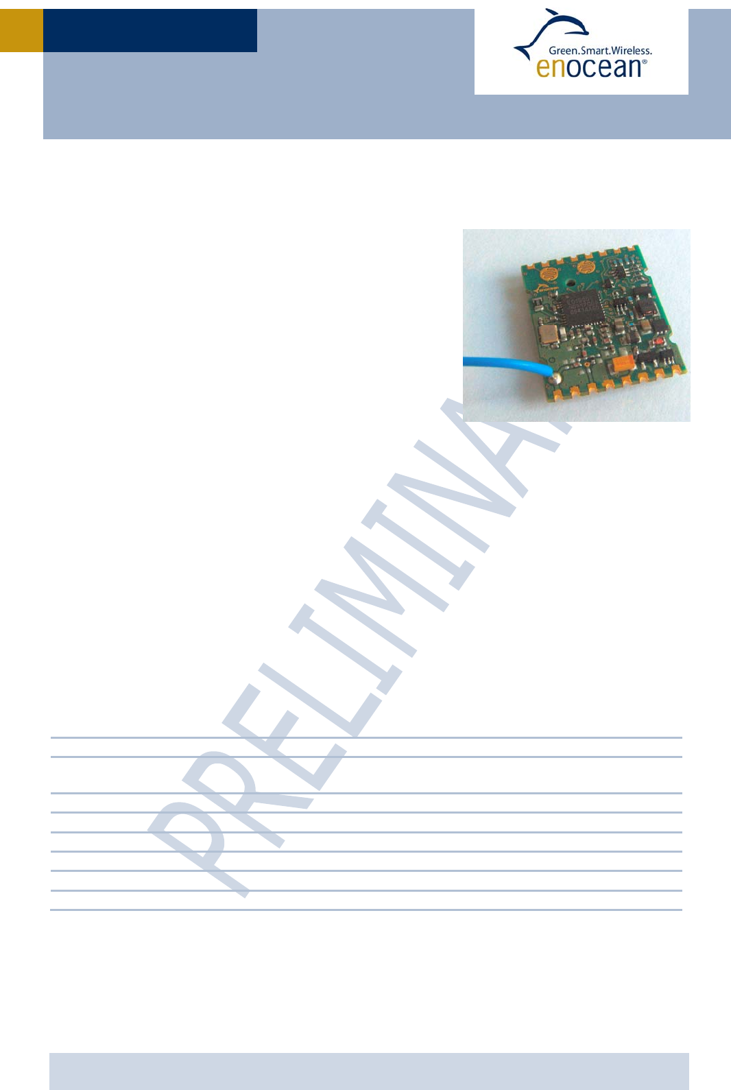
The radio transmitter module PTM 330 from EnOcean
enables the implementation of wireless sensors and
switches without batteries.
Key applications are handheld remote controls or indus-
trial switches.
Functional Principle
When an energy pulse is supplied (e.g. by ECO 200 from
EnOcean) an RF telegram is transmitted including a
unique 32-bit module ID, the polarity of the energy
pulse, and the operating status of 4 digital inputs. The
RPS telegram content can be configured if other content is needed.
PTM 330 can be connected to ECO 200 via a contact spring. There are two meander struc-
tures on the PCB which allow usage of a rubber pad to set the level of two digital inputs.
Alternatively PTM 330 can be mounted as an SMD component onto a host PCB. In this case
energy supply pins and digital input pins are accessible via contact pads.
Product variants
PTM 330: 868MHz variant, pre-installed whip antenna, delivery in card board box
PTM 332: 868MHz variant, no pre-installed antenna, delivery as tape & reel
PTM 330C: 315MHz variant, pre-installed whip antenna, delivery in card board box
PTM 332C: 315MHz variant, no pre-installed antenna, delivery as tape & reel
1.2 Technical Data
Power supply ECO 200 or equivalent energy pulse
Antenna pre-installed whip antenna PTM 330/330C
external 50 Ohm or whip antenna PTM 332/332C
Frequency 868.3 MHz (PTM 33x) / 315.0 MHz (PTM 33xC)
Transmission power typ. 2 dBm at antenna base
Data rate / Modulation type 125 kbps / ASK
Telegram type RPS of type 2 (allows interpretation of operating two buttons simultaneously)
Digital inputs 4
Transmission range up to 200 m free field, up to 30 m indoo
r
USER MANUA
L
V0.8
© 2009 EnOcean | www.enocean.com PTM 33x / 33xC User Manual V0.8 | Page 5/20
PTM 33X / 33XC
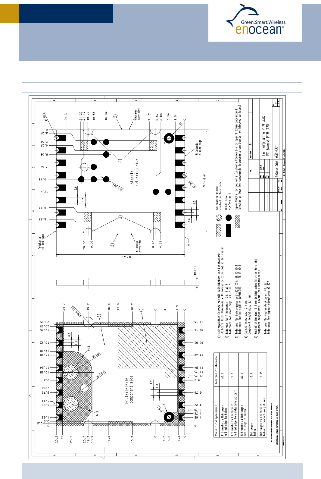
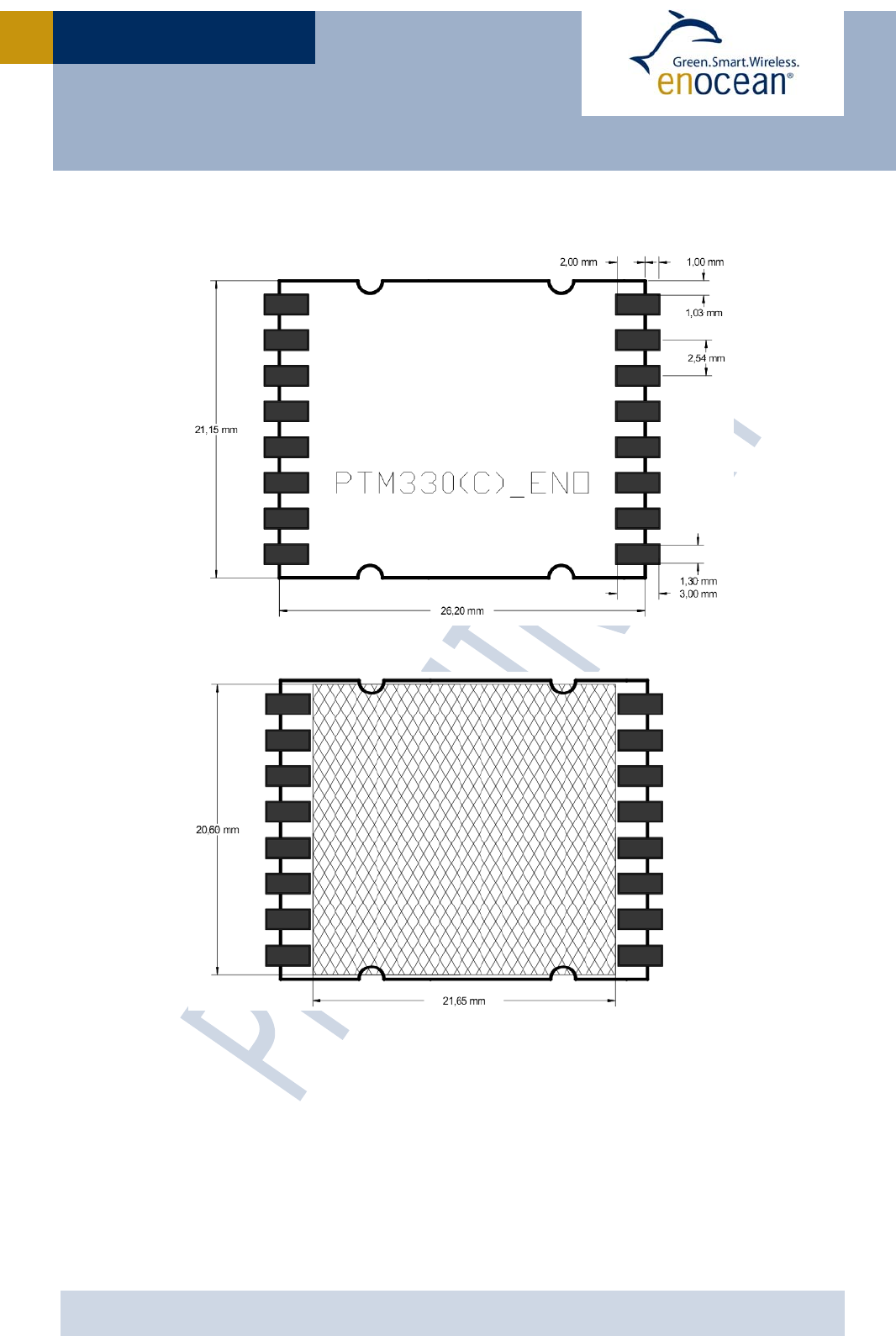
1.3 Physical Dimensions
PCB dimensions 26.2 x 21.15 x 3.5 mm
USER MANUA
L
V0.8
© 2009 EnOcean | www.enocean.com PTM 33x / 33xC User Manual V0.8 | Page 6/20
PTM 33X / 33XC
1.4 Environmental Conditions
Operating temperature -25 °C … +85 °C
Storage temperature -40 °C … +85 °C
Storage temperature in Tape&Reel -20 °C … +50 °C
Humidity 0% … 93% r.h., non-condensing
1.5 Ordering Information
Type Ordering Code Frequency Note
PTM 330 S3001-A330 868.3 MHz Whip antenna mounted
Card board box
PTM 332 S3001-A332 868.3 MHz No antenna mounted
Tape & Reel
PTM 330C S3031-A330 315.0 MHz Whip antenna mounted
Card board box
PTM 332C S3031-A332 315.0 MHz No antenna mounted
Tape & Reel
2 FUNCTIONAL DESCRIPTION
2.1 Block diagram
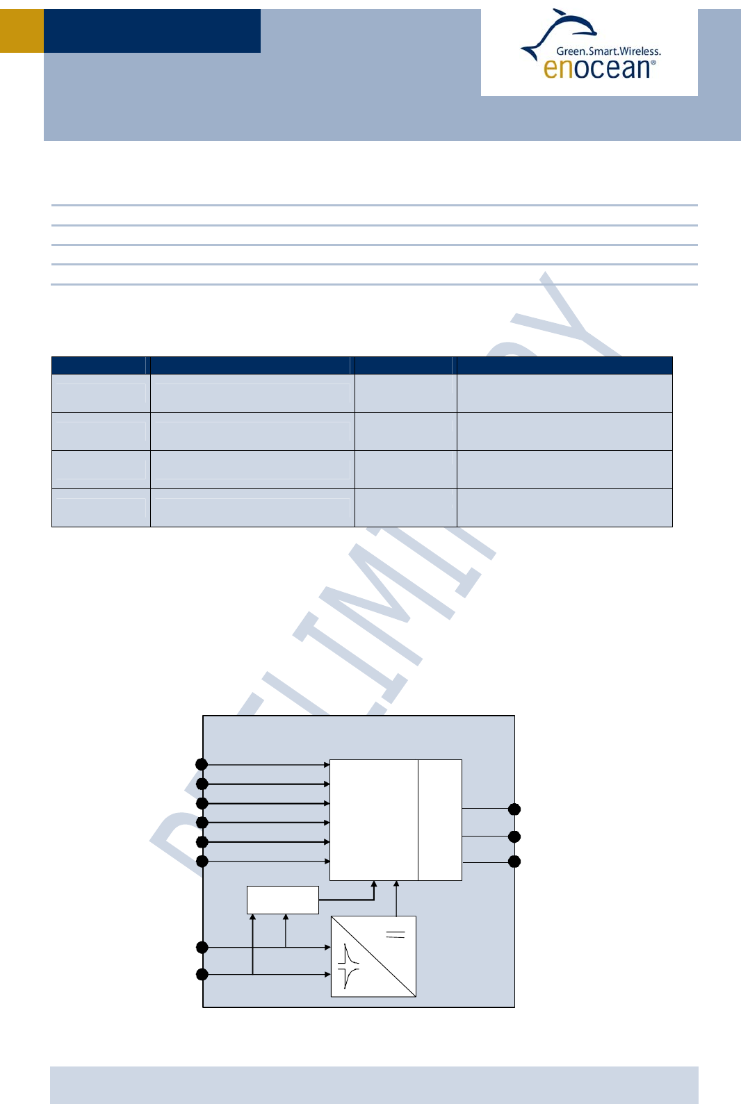
At power-up by an energy pulse at AC1, AC2 a DC voltage is provided to the internal micro
controller. The microcontroller reads the polarity of the supply voltage pulse and the status
of the digital inputs A0, A1, B0, B1. After that 3 identical radio telegrams calculated from
the status of these inputs are transmitted.
RF
Power
Converter
GND
AC1
AC2
RF_50
PTM33x
RF_WHIP
A0
A1
µC
B0
B1
Polarity
Detection
GND
CFG

USER MANUA
L
V0.8
© 2009 EnOcean | www.enocean.com PTM 33x / 33xC User Manual V0.8 | Page 7/20
PTM 33X / 33XC
2.2 Pin out
2.3 Pin Description and operational characteristics
Symbol Function Characteristics
GND Ground connection Must be connected to GND
V+ For test purposes only Do not connect
B0
O-Button Rocker B Digital input, leave open or connect to GND
Internal pull-up
B1
I-Button Rocker B Digital input, leave open or connect to GND
Internal pull-up
A0
O-Button Rocker A Digital input, leave open or connect to GND
Internal pull-up
A1
I-Button Rocker A Digital input, leave open or connect to GND
Internal pull-up
CFG Activate VOFF comparator
when connected to GND
Must be connected to GND when used with
equivalent energy pulse instead of ECO 200
Internal pull-up
AC1 Input for ECO 200 ECO 200 or equivalent energy pulse
AC2 Input for ECO 200 ECO 200 or equivalent energy pulse
RF_WHIP RF output Output for whip antenna
RF_50 RF output 50 Ohm output for external antenna
T1-9 Configuration Interface See 2.4
1
2
3
4
5
6
7
8
11
10
9
12
13
14
15
16
GND
CFG
B0
GND
B1
A0
GND
A1
AC1
AC2
GND
V+
GND
RF_50
GND
RF_WHIP
AC1
AC1
AC2
AC2
On back side of PCB
T4 T3 T8
T6
T5
T9T7
T1 T2
USER MANUA
L
V0.8
© 2009 EnOcean | www.enocean.com PTM 33x / 33xC User Manual V0.8 | Page 8/20
PTM 33X / 33XC
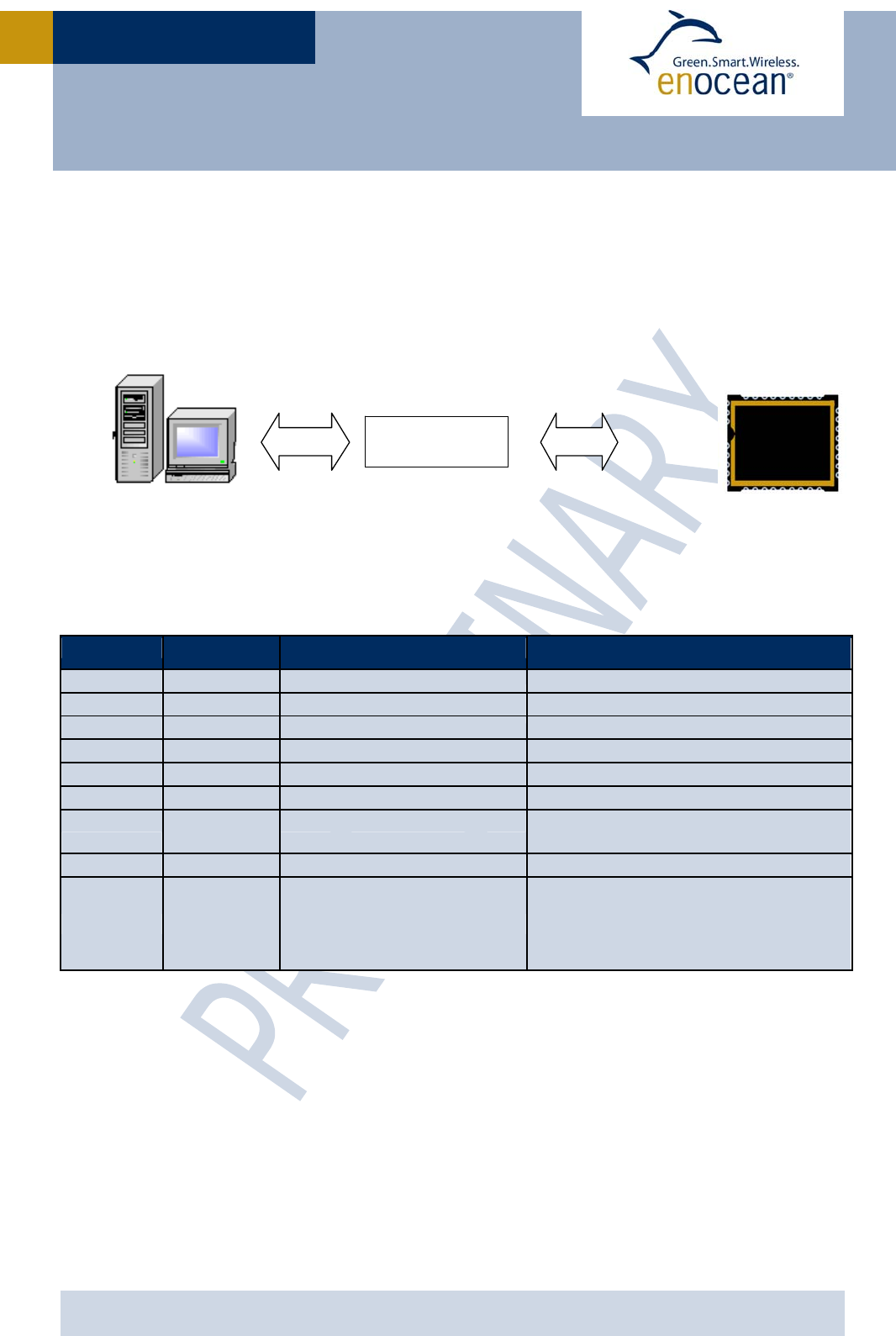
2.4 Configuration Interface
Via the programming interface the telegram content can be modified.
The interface is shown in the figure below:
EnOcean provides EOPx (EnOcean Programmer, a command line program) and Dolphin Stu-
dio (Windows application for chip configuration, programming, and testing) and the
USB/SPI programmer device as part of the EDK 300 developer’s kit.
Pin Symbol Function Characteristics
T1 VDD Supply voltage Interface to programmer
T2 GND Ground connection Interface to programmer
T3 SCSEDIO0 SPI chip select Interface to programmer
T4 SCLKDIO1 SPI serial clock Interface to programmer
T5 WSDADIO2 SPI input Interface to programmer
T6 RSDADIO3 SPI output Interface to programmer
T7
RESET Reset Interface to programmer, internal
pull down
T8 ADIO7 Sync output
T9 PROG_EN Enable programming mode
Interface to programmer
HIGH: programming mode active
LOW: operating mode
Internal pull-down
USB <=> SPI
interface
S
PI
U
S
B
Dolphin Studio, or EOPx
Reset
PROG_EN
ADIO7
SCSEDIO0
SCLKDIO1
WSDADIO2
RSDADIO3
PTM
330

USER MANUA
L
V0.8
© 2009 EnOcean | www.enocean.com PTM 33x / 33xC User Manual V0.8 | Page 9/20
PTM 33X / 33XC
2.5 Absolute maximum ratings (non operating)
Symbol Parameter Min Max Units
AC1
AC2 Supply voltage 0 6.4 V
GND Ground connection 0 0 V
A0
A1
B0
B1
Voltage digital input pins
0 0 V
2.6 Maximum Ratings (operating)
Symbol Parameter Min Max Units
AC1
AC2 Supply voltage 0 6.0 V
GND Ground connection 0 0 V
A0
A1
B0
B1
Voltage digital input pins
0 0 V

USER MANUA
L
V0.8
© 2009 EnOcean | www.enocean.com PTM 33x / 33xC User Manual V0.8 | Page 10/20
PTM 33X / 33XC
2.7 Radio telegram
2.7.1 Normal operation
In default configuration PTM 33x transmits the same telegrams as a PTM 200 radio switch:
Telegram type RPS: There are two message types depending on how many buttons
(A0, A1, B0, B1) have been pressed (connected to GND)
o N-message: Only one or two buttons have been pressed.
o U-message: No pushbutton was pressed when activating the energy genera-
tor, or more than two pushbuttons have been pressed.
Unique factory programmed 32 bit ID
DATA_BYTE2, DATA_BYTE1, DATA_BYTE0=0
DATA_BYTE3 and STATUS as follows:
N-message:
DATA_BYTE3:
7 0
RID UD PR SRID SUD SA
RID (2 bit) Rocker ID, A=0, B=1
UD (1 bit) UD=1 Æ O-button, UD=0 Æ I-button
PO (1 bit) Polarity, see table below
SRID (2 bit) Second Rocker ID
SUD (1 bit) (Second) SUD=1 Æ O-button, SUD=0 Æ I-button
SA (1 bit) SA=1 Æ Second action (2 buttons pressed
simultaneously), SA=0 Æ No second action
STATUS:
7 0
Reserved T21 NU RP_COUNTER
Reserved (2 bit) For future use
T21 (1 bit) 1
NU (1 bit) NU=1 Æ N-message.
RP_COUNTER (4 bit) Repeater level: 0 is original message (not repeated)
USER MANUA
L
V0.8
© 2009 EnOcean | www.enocean.com PTM 33x / 33xC User Manual V0.8 | Page 11/20
PTM 33X / 33XC
U-message:
DATA_BYTE3:
7 0
BUTTONS PR Reserved
BUTTONS (3 bit) Number of simultaneously pressed buttons, as following:
0 = 0 Button
1 = not possible
2 = not possible
3 = 3 or 4 buttons
4 = not possible
5 = not possible
6 = not possible
7 = not possible
PO (1 bit) Polarity, see table below
Reserved (4 bit)
STATUS:
7 0
Reserved T21 NU RP_COUNTER
Reserved (2 bit) For future use
T21 (1 bit) 1
NU (1 bit) NU=0 Æ U-message.
RP_COUNTER (4 bit) Repeater level: 0 is original message (not repeated)
The polarity PO is defined as follows:
2.7.2 User defined operation
Via the configuration interface it is possible to define different content of DATA_BYTE3 and
define if a N-message or U-message shall be sent. This allows for example to transmit
other ORG=5 telegrams, e.g. “Mechanical handle”, as described in the EnOcean Equipment
Profiles defined by EnOcean Alliance.
2.8 Transmit timing
The setup of the transmission timing allows avoiding possible collisions with data packages
of other EnOcean transmitters as well as disturbances from the environment. With each
transmission cycle, 3 identical subtelegrams are transmitted within 40 ms. The transmis-
sion of a subtelegram lasts approximately 0.7 ms. The delay between the three transmis-
sion bursts is affected at random.
AC1 AC2 PO
- + 1
+ - 0
USER MANUA
L
V0.8
© 2009 EnOcean | www.enocean.com PTM 33x / 33xC User Manual V0.8 | Page 12/20
PTM 33X / 33XC
3 APPLICATIONS INFORMATION
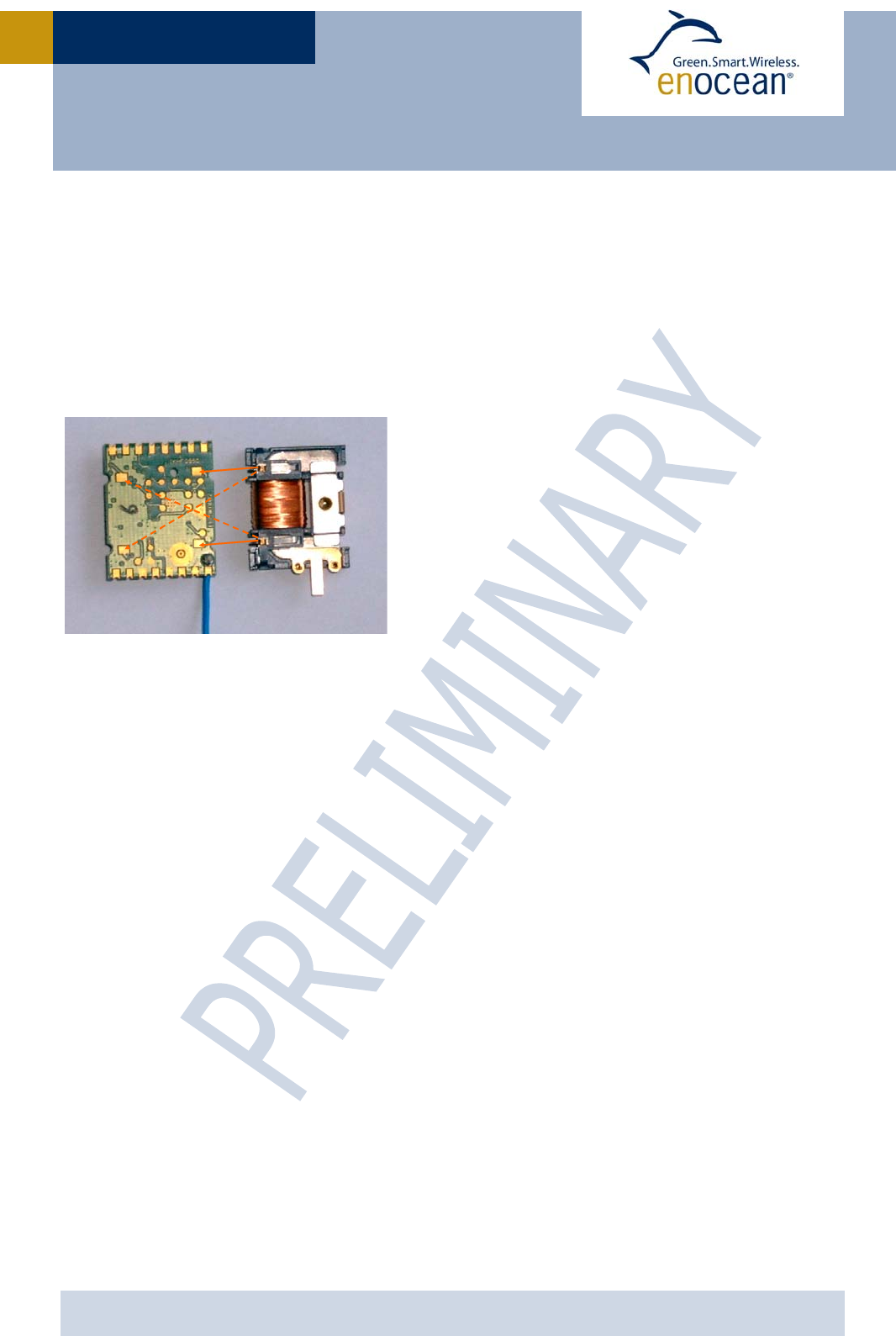
3.1 How to connect an energy harvester
PTM 330 can be connected to ECO 200 without soldering. ECO 200 provides contact springs
which can directly be connected to contact pads of PTM 330. The contact pads on the bot-
tom of the PCB are shown below (left). A second orientation where PTM 330 is rotated 180°
with respect to ECO 200 is also possible as shown with dashed lines.
3.2 How to generate an equivalent energy pulse
USER MANUA
L
V0.8
© 2009 EnOcean | www.enocean.com PTM 33x / 33xC User Manual V0.8 | Page 13/20
PTM 33X / 33XC
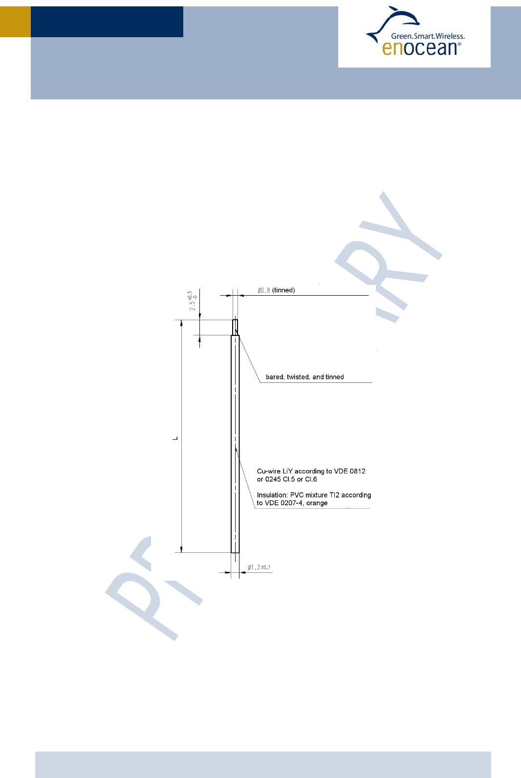
3.3 Antenna
315 MHz
Option 1: 150 mm wire, connect to RF_WHIP
Option 2: A 50Ω antenna can be connected to RF_50.
In this case the limited modular FCC/IC approval is not valid!
An FCC/IC approval is then needed for the end device!
868 MHz
Option 1: 87 mm wire, connect to RF_WHIP
Option 2: A 50 Ω antenna can be connected to RF_50
Specification of the whip antenna; L=150 mm @ 315 MHz, L=87 mm @ 868 MHz
USER MANUA
L
V0.8
© 2009 EnOcean | www.enocean.com PTM 33x / 33xC User Manual V0.8 | Page 14/20
PTM 33X / 33XC
3.4 Layout recommendations
Proposal for foot print on host PCB
Keep out area on host PCB. No copper surface area allowed!
USER MANUA
L
V0.8
© 2009 EnOcean | www.enocean.com PTM 33x / 33xC User Manual V0.8 | Page 15/20
PTM 33X / 33XC
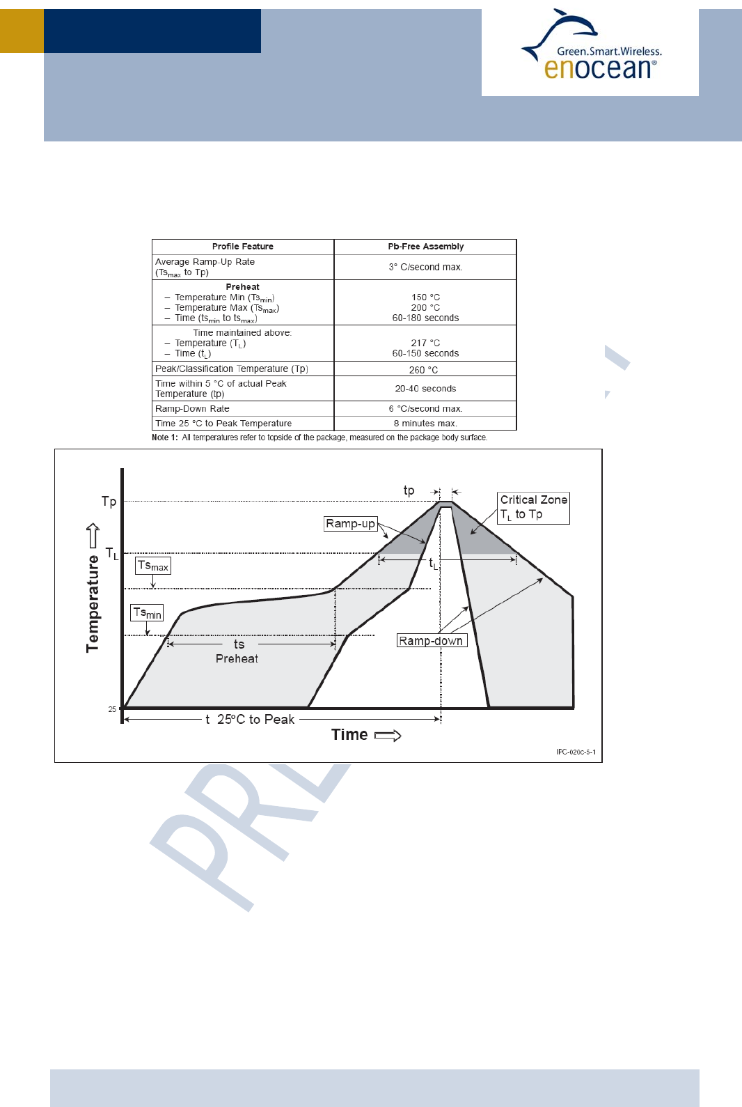
3.5 Soldering information PTM 332/332C
PTM 332 has to be soldered according to IPC/JEDEC J-STD-020C standard.
PTM 332 shall be handled according to Moisture Sensitivity Level MSL4 which means a floor
time of 72 h. PTM 332 may be soldered only once, since one time is already consumed at
production of the module itself.
Once the dry pack bag is opened, the desired quantity of units should be removed and the
bag resealed within two hours. If the bag is left open longer than 30 minutes the desiccant
should be replaced with dry desiccant. If devices have exceeded the specified floor life time
of 72 h, they may be baked according IPC/JEDEC J-STD-033B.
Devices packaged in moisture-proof packaging should be stored in ambient conditions not
exceeding temperatures of 40 °C or humidity levels of 90% r.h..
PTM 332 modules have to be soldered within 6 months after delivery!

USER MANUA
L
V0.8
© 2009 EnOcean | www.enocean.com PTM 33x / 33xC User Manual V0.8 | Page 16/20
PTM 33X / 33XC
3.6 Transmission range
The main factors that influence the system transmission range are type and location of the
antennas of the receiver and the transmitter, type of terrain and degree of obstruction of
the link path, sources of interference affecting the receiver, and “Dead” spots caused by
signal reflections from nearby conductive objects. Since the expected transmission range
strongly depends on this system conditions, range tests should categorically be performed
before notification of a particular range that will be attainable by a certain application.
The following figures for expected transmission range are considered by using a PTM, a
STM or a TCM radio transmitter device and the TCM radio receiver device with preinstalled
whip antenna and may be used as a rough guide only:
Line-of-sight connections: Typically 30 m range in corridors, up to 100 m in halls
Plasterboard walls / dry wood: Typically 30 m range, through max. 5 walls
Line-of-sight connections: Typically 30 m range in corridors, up to 100 m in halls
Ferroconcrete walls / ceilings: Typically 10 m range, through max. 1 ceiling
Fire-safety walls, elevator shafts, staircases and supply areas should be considered as
screening.
The angle at which the transmitted signal hits the wall is very important. The effective wall
thickness – and with it the signal attenuation – varies according to this angle. Signals
should be transmitted as directly as possible through the wall. Wall niches should be
avoided. Other factors restricting transmission range:
Switch mounted on metal surfaces (up to 30% loss of transmission range)
Hollow lightweight walls filled with insulating wool on metal foil
False ceilings with panels of metal or carbon fiber
Lead glass or glass with metal coating, steel furniture
The distance between EnOcean receivers and other transmitting devices such as com-
puters, audio and video equipment that also emit high-frequency signals should be at least
0.5 m
A summarized application note to determine the transmission range within buildings is
available as download from www.enocean.com.

USER MANUA
L
V0.8
© 2009 EnOcean | www.enocean.com PTM 33x / 33xC User Manual V0.8 | Page 17/20
PTM 33X / 33XC
4 AGENCY CERTIFICATIONS (in preparation)
The modules have been tested to fulfil the approval requirements for CE (PTM 33x) and
FCC/IC (PTM 33xC) based on the built-in firmware.
4.1 CE approval
The modules bear the EC conformity marking CE and conforms to the R&TTE EU-directive
on radio equipment. The assembly conforms to the European and national requirements of
electromagnetic compatibility. The conformity has been proven and the according docu-
mentation has been deposited at EnOcean. The modules can be operated without notifica-
tion and free of charge in the area of the European Union, and in Switzerland. The following
provisos apply:
• EnOcean RF modules must not be modified or used outside their specification
limits.
• EnOcean RF modules may only be used to transfer digital or digitized data.
Analog speech and/or music are not permitted.
• The final product incorporating EnOcean RF modules must itself meet the es-
sential requirement of the R&TTE Directive and a CE marking must be affixed
on the final product and on the sales packaging each. Operating instructions
containing a Declaration of Conformity has to be attached.
• If the transmitter is used according to the regulations of the 868.3 MHz band,
a so-called “Duty Cycle” of 1% per hour must not be exceeded. Permanent
transmitters such as radio earphones are not allowed.
• The module must be used with only the following approved antenna(s).
Type Parameter Value
Wire/Monopole at RF_WHIP Maximum gain 1.0 dBi
External antenna at RF_50 Antenna type Passive
Impedance ~50 Ohm
Maximum gain ≤ 0 dBd

USER MANUA
L
V0.8
© 2009 EnOcean | www.enocean.com PTM 33x / 33xC User Manual V0.8 | Page 18/20
PTM 33X / 33XC
4.2 FCC (United States) Certification
PTM330C and PTM332C LIMITED MODULAR APPROVAL
This is an RF module approved for Limited Modular use operating as an intentional trans-
mitting device with respect to 47 CFR 15.231(a-c) and is limited to OEM installation. The
module is optimized to operate using small amounts of energy, and may be powered by a
battery. The module transmits short radio packets comprised of control signals, (in some
cases the control signal may be accompanied with data) such as those used with alarm sys-
tems, door openers, remote switches, and the like. The module does not support continu-
ous streaming of voice, video, or any other forms of streaming data; it sends only short
packets containing control signals and possibly data. The module is designed to comply
with, has been tested according to 15.231(a-c), and has been found to comply with each
requirement. Thus, a finished device containing the PTM330C/PTM332C radio module can
be operated in the United States without additional Part 15 FCC approval (approval(s) for
unintentional radiators may be required for the OEM’s finished product), under EnOcean’s
FCC ID number. This greatly simplifies and shortens the design cycle and development
costs for OEM integrators. The module can be triggered manually or automatically, which
cases are described below.
Manual Activation
The radio module can be configured to transmit a short packetized control signal if trig-
gered manually. The module can be triggered, by pressing a switch, for example.
The packet contains one (or more) control signals that is(are) intended to control some-
thing at the receiving end. The packet may also contain data. Depending on how much en-
ergy is available from the energy source, subsequent manual triggers can initiate the
transmission of additional control signals. This may be necessary if prior packet(s)
was(were) lost to fading or interference. Subsequent triggers can also be initiated as a pre-
caution if any doubt exists that the first packet didn’t arrive at the receiver. Each packet
that is transmitted, regardless of whether it was the first one or a subsequent one, will only
be transmitted if enough energy is available from the energy source.
Automatic Activation
The radio module also can be configured to transmit a short packetized control signal
if triggered automatically. Again, the packet contains a control signal that is intended to
control something at the receiving end and may also contain data. As above, it is possible
for the packet to get lost and never reach the receiver. However, if enough energy is avail-
able from the energy source, and the module has been configured to do so, then another
packet or packets containing the control signal may be transmitted at a later time.
OEM Requirements
In order to use EnOcean’s FCC ID number, the OEM must ensure that the following condi-
tions are met:
End users of products, which contain the module, must not have the ability to alter the
firmware that governs the operation of the module. The agency grant is valid only when
the module is incorporated into a final product by OEM integrators.
The end-user must not be provided with instructions to remove, adjust or install the
module.

USER MANUA
L
V0.8
© 2009 EnOcean | www.enocean.com PTM 33x / 33xC User Manual V0.8 | Page 19/20
PTM 33X / 33XC
The Original Equipment Manufacturer (OEM) must ensure that FCC labeling require-
ments are met. This includes a clearly visible label on the outside of the final product.
Attaching a label to a removable portion of the final product, such as a battery cover, is
not permitted. The label must include the following text:
Contains FCC ID: SZV-PTM33XC
The enclosed device complies with Part 15 of the FCC Rules. Operation is subject to
the following two conditions: (i.) this device may not cause harmful interference and
(ii.) this device must accept any interference received, including interference that
may cause undesired operation.
The user manual for the end product must also contain the text given above.
Changes or modifications not expressly approved by EnOcean could void the user's au-
thority to operate the equipment.
The module must be used with only the following approved antenna(s).
The OEM must ensure that timing requirements according to 47 CFR 15.231(a-c) are
met.
The OEM must sign the OEM Limited Modular Approval Agreement with EnOcean
Part Number Type Gain
N.A. Wire/Monopole 1.0 dBi

USER MANUA
L
V0.8
© 2009 EnOcean | www.enocean.com PTM 33x / 33xC User Manual V0.8 | Page 20/20
PTM 33X / 33XC
4.3 IC (Industry Canada) Certification
In order to use EnOcean’s IC number, the OEM must ensure that the following conditions
are met:
Labeling requirements for Industry Canada are similar to those required by the FCC.
The Original Equipment Manufacturer (OEM) must ensure that IC labeling requirements
are met. A clearly visible label on the outside of a non-removable part of the final prod-
uct must include the following text:
Contains IC: 5713A-PTM33XC
The OEM must sign the OEM Limited Modular Approval Agreement with EnOcean