EnOcean STM311C Transmitter Module User Manual
EnOcean GmbH Transmitter Module
UserManual.wiki
>
EnOcean
>
STM311C User Manual
User Manual
Navigation menu
Upload a User Manual
Namespaces
Wiki Guide
HTML
PDF
Info
Views
User Manual
Discussion / Help
Navigation
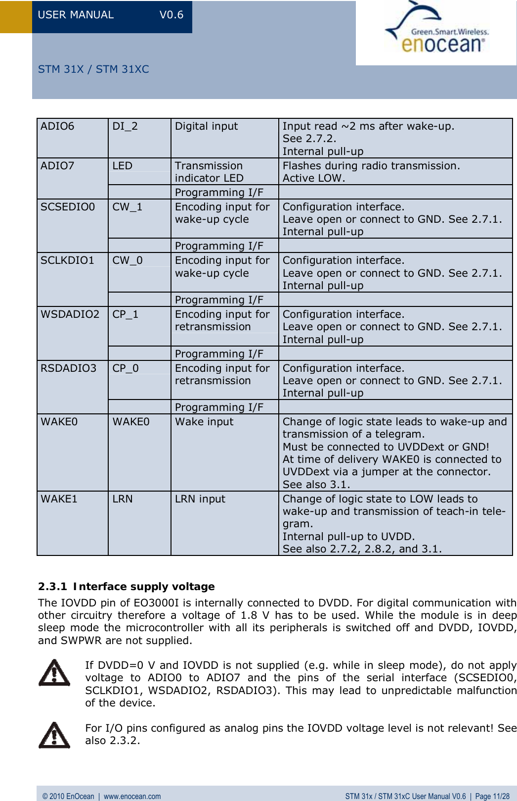
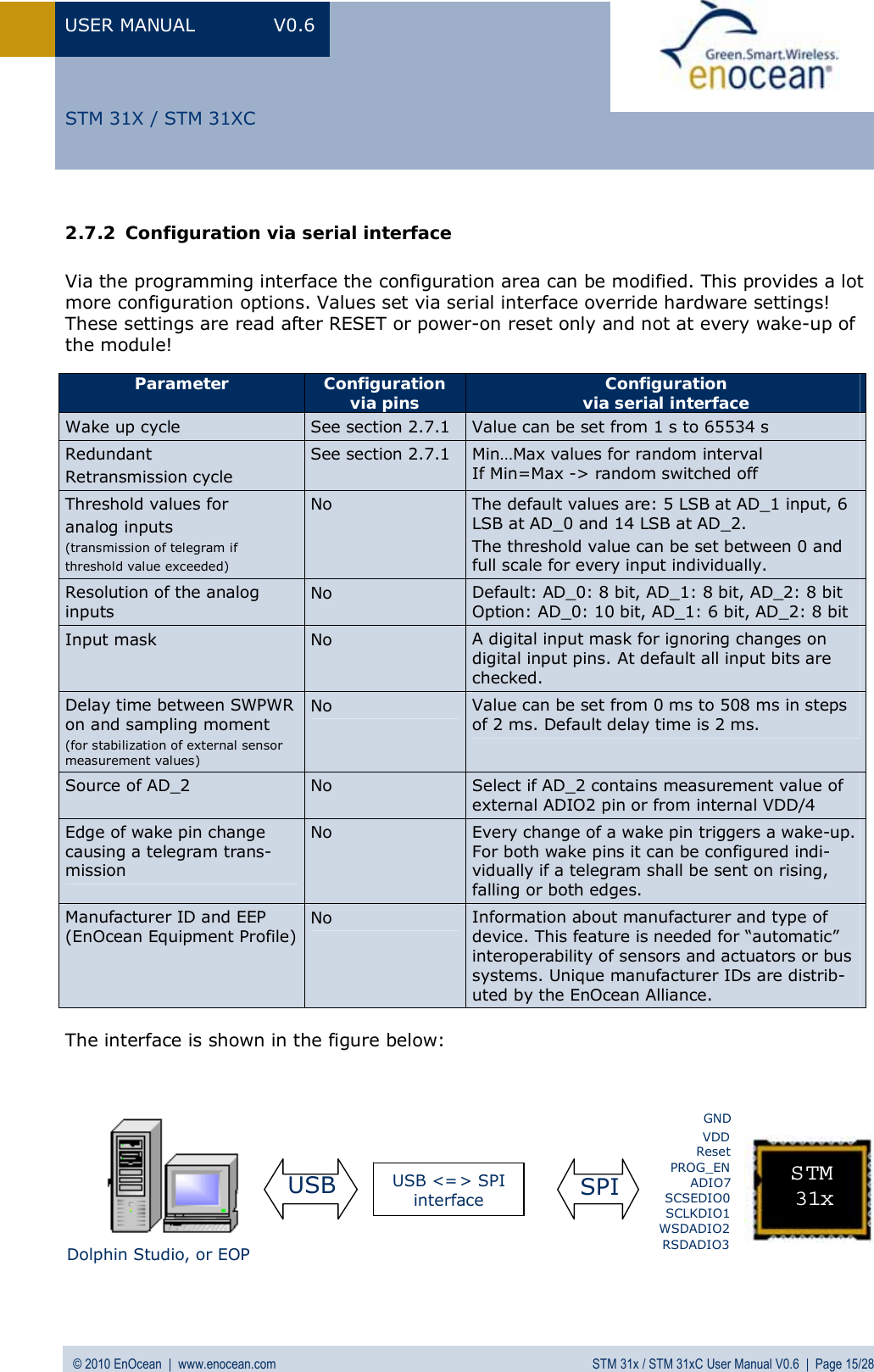

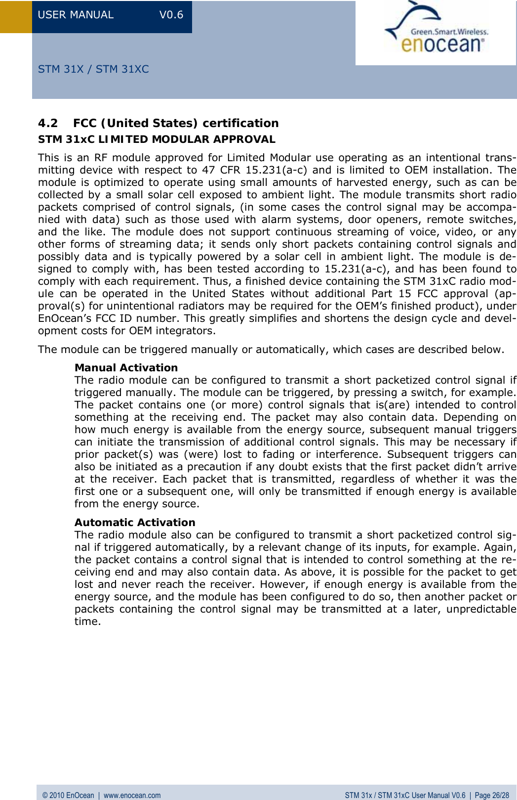
![USER MANUAL V0.6 © 2010 EnOcean | www.enocean.com STM 31x / STM 31xC User Manual V0.6 | Page 18/28 STM 31X / STM 31XC2.10 Charging circuitry The figure below shows the internal charging circuit. It is controlled via the WXODIO pin of EO3000I which switches according to the status of the internal threshold detector. For de-tails please refer to our Dolphin Core Description documentation. An external 3 V battery can be connected at VDD (STM 312 only) or at VGC. 2.11 Energy consumption Current Consumption of STM 31x Charge needed for one measurement and transmit cycle: ~130 µC Charge needed for one measurement cycle without transmit: ~30 µC (current for external sensor circuits not included) Calculations are performed on the basis of electric charges because of the internal linear voltage regulator of the module. Energy consumption varies with voltage of the energy storage while consumption of electric charge is constant. 0.000010.00010.0010.010.11101000 102030405060708090100Time [ms]C u rre n t [mA]](https://usermanual.wiki/EnOcean/STM311C/User-Guide-1349384-Page-18.png)
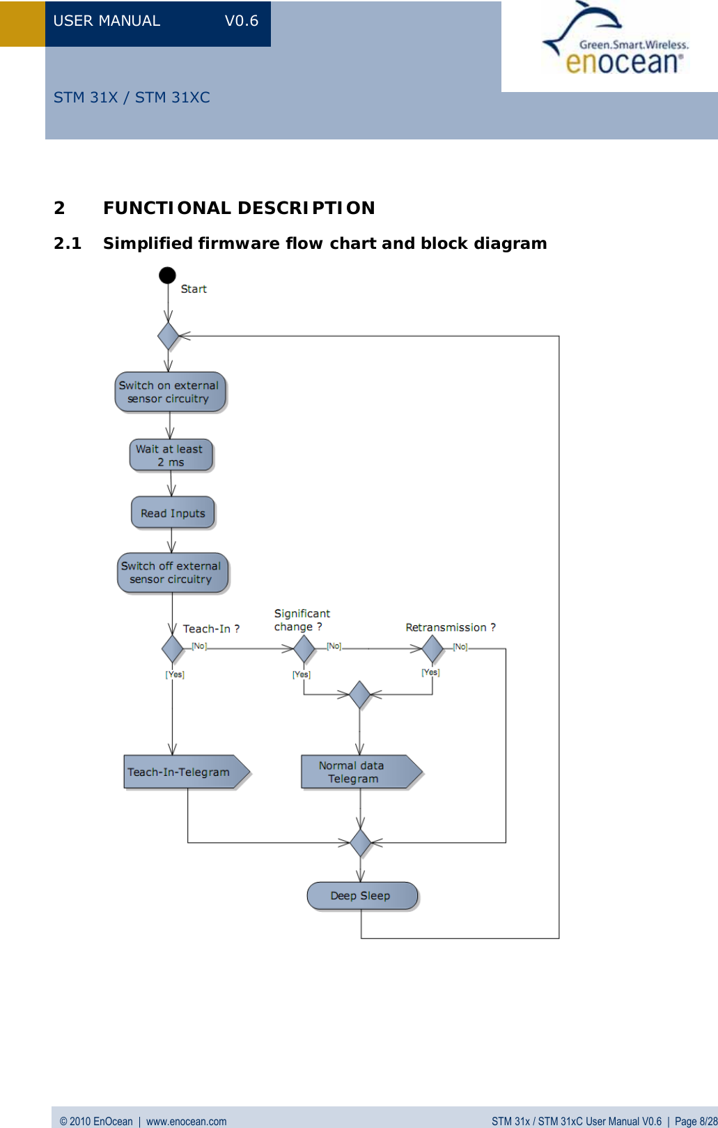
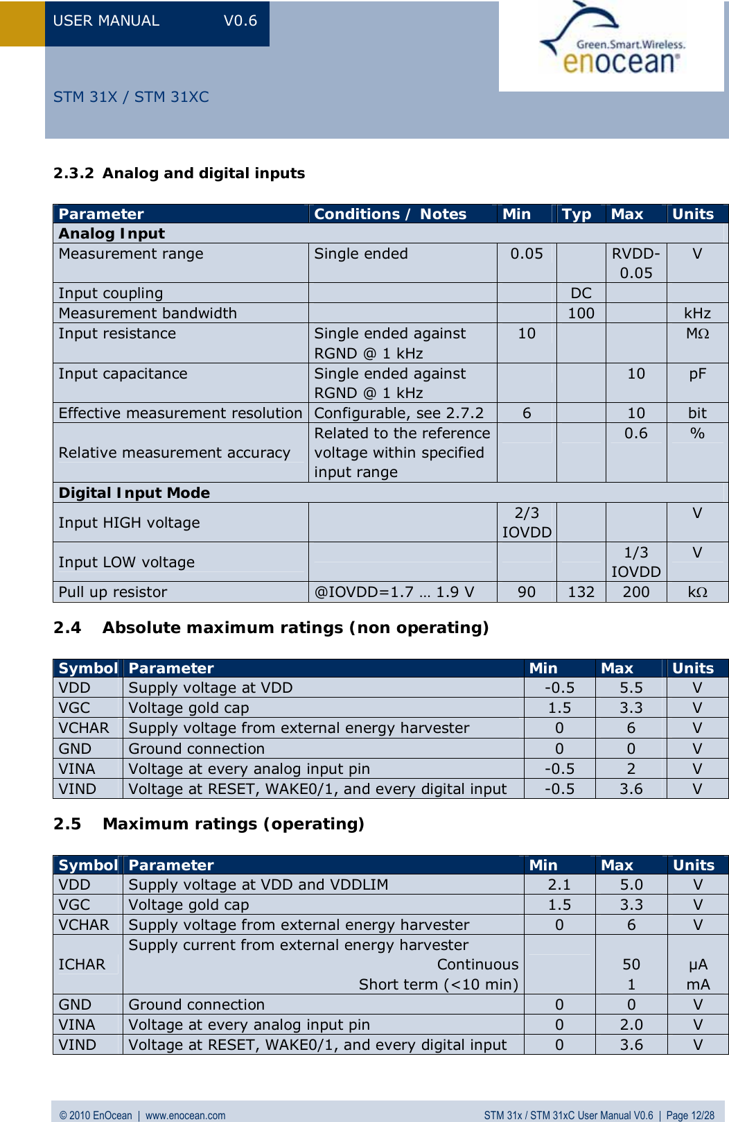
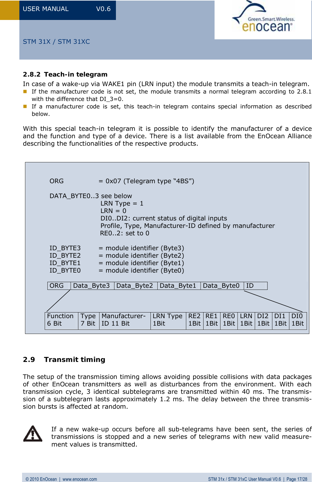
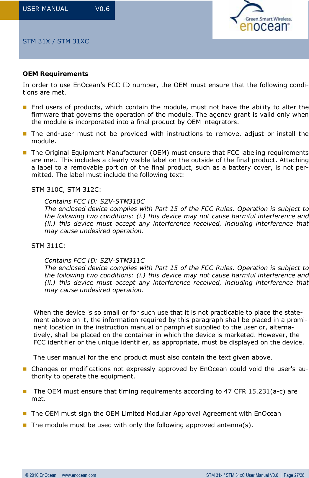
![USER MANUAL V0.6 © 2010 EnOcean | www.enocean.com STM 31x / STM 31xC User Manual V0.6 | Page 19/28 STM 31X / STM 31XCFrom these values the following performance parameters have been calculated: Wake cycle [s] Transmit interval Operation Time in darkness [h] when storage fully charged Required reload time [h] at 200 lux within 24 h for continuous operation 24 h operation after 6 h illumination at x lux Illumina-tion level in lux for continuous operation Current in µA required for con-tinuous operation1 1 0.5 storage too sm all storage too sm all 5220 130.51 10 1.7 storage too sm all storage too sm all 1620 40.51 100 2.1 storage too sm all storage too sm all 1250 31.310 1 5.1 storage too sm all storage too sm all 540 13.510 10 16 21 700 175 4.410 100 20 16.8 560 140 3.5100 1 43 7.8 260 65 1.6100 10 98 3.6 120 30 0.8100 100 112 3 100 25 0.6 Assumptions: Internal storage PAS614L-VL3 with 0.25 F, Umax=3.2 V, Umin=2.2 V, T=25 °C Consumption: Transmit cycle 100 µC, measurement cycle 30 µC Pre-installed solar cell ECS 300, operating values 3 V and 5 µA @ 200 lux fluorescent light Current proportional to illumination level (not true at very low levels!) These values are calculated values, the accuracy is about +/-20%!](https://usermanual.wiki/EnOcean/STM311C/User-Guide-1349384-Page-19.png)
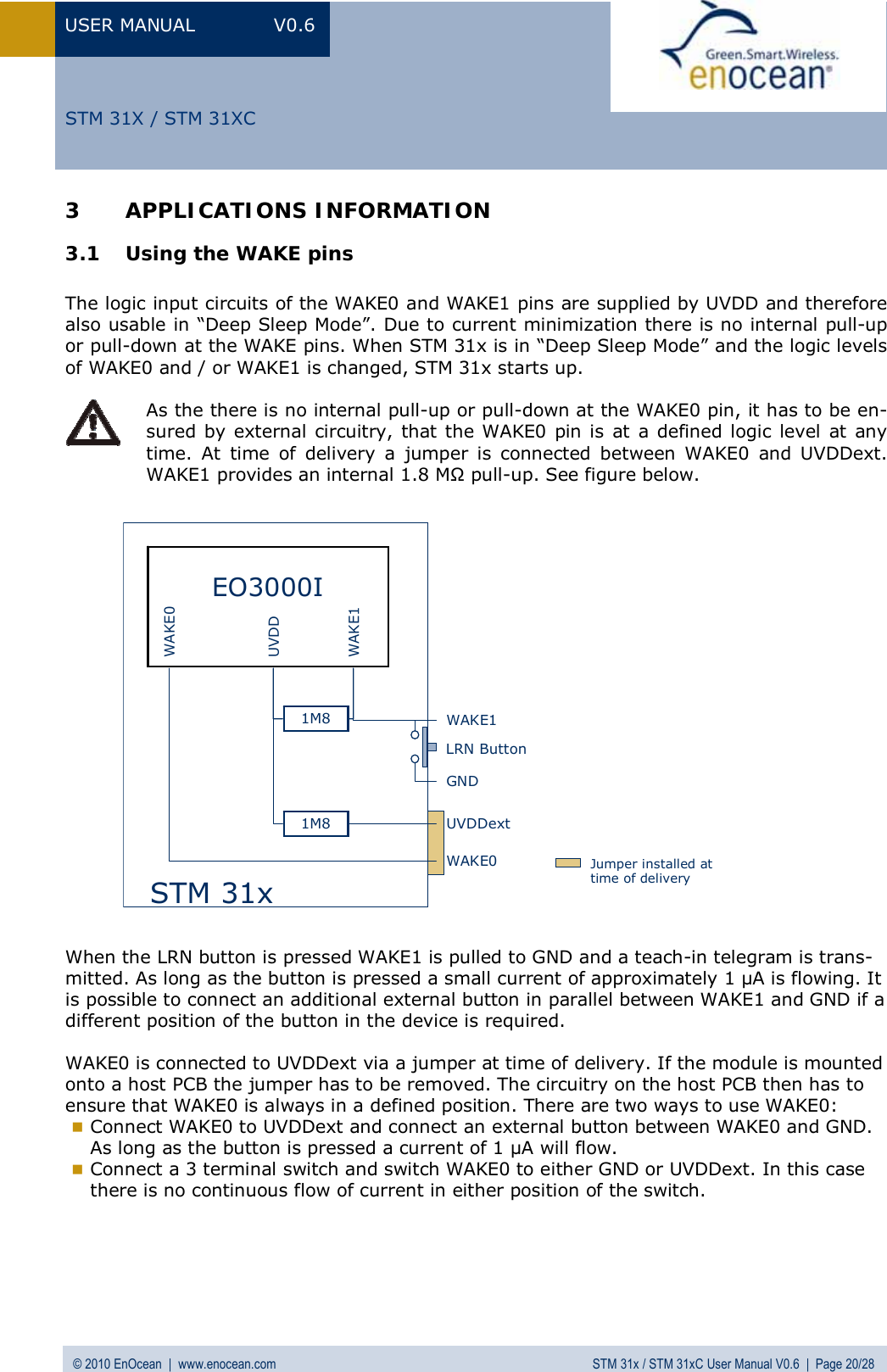
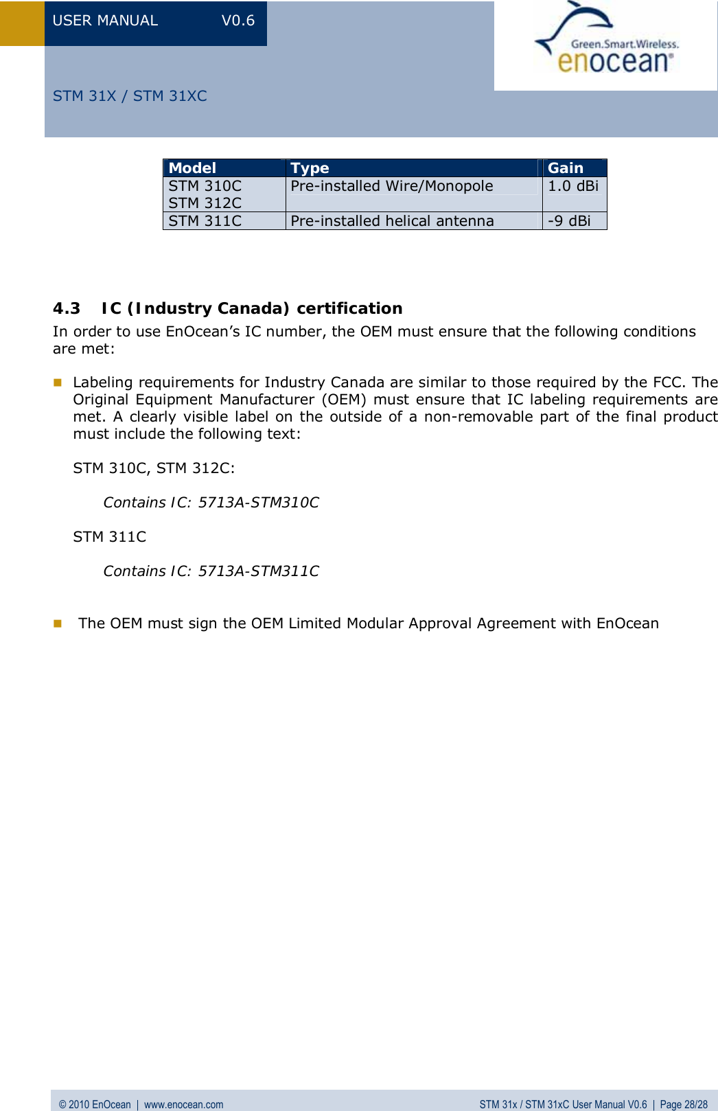

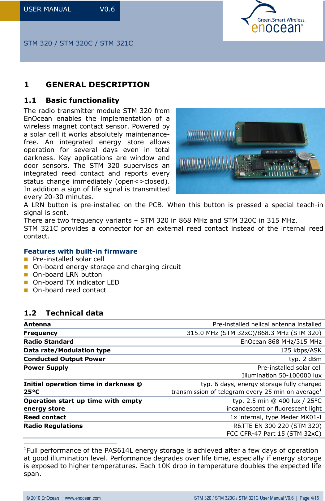
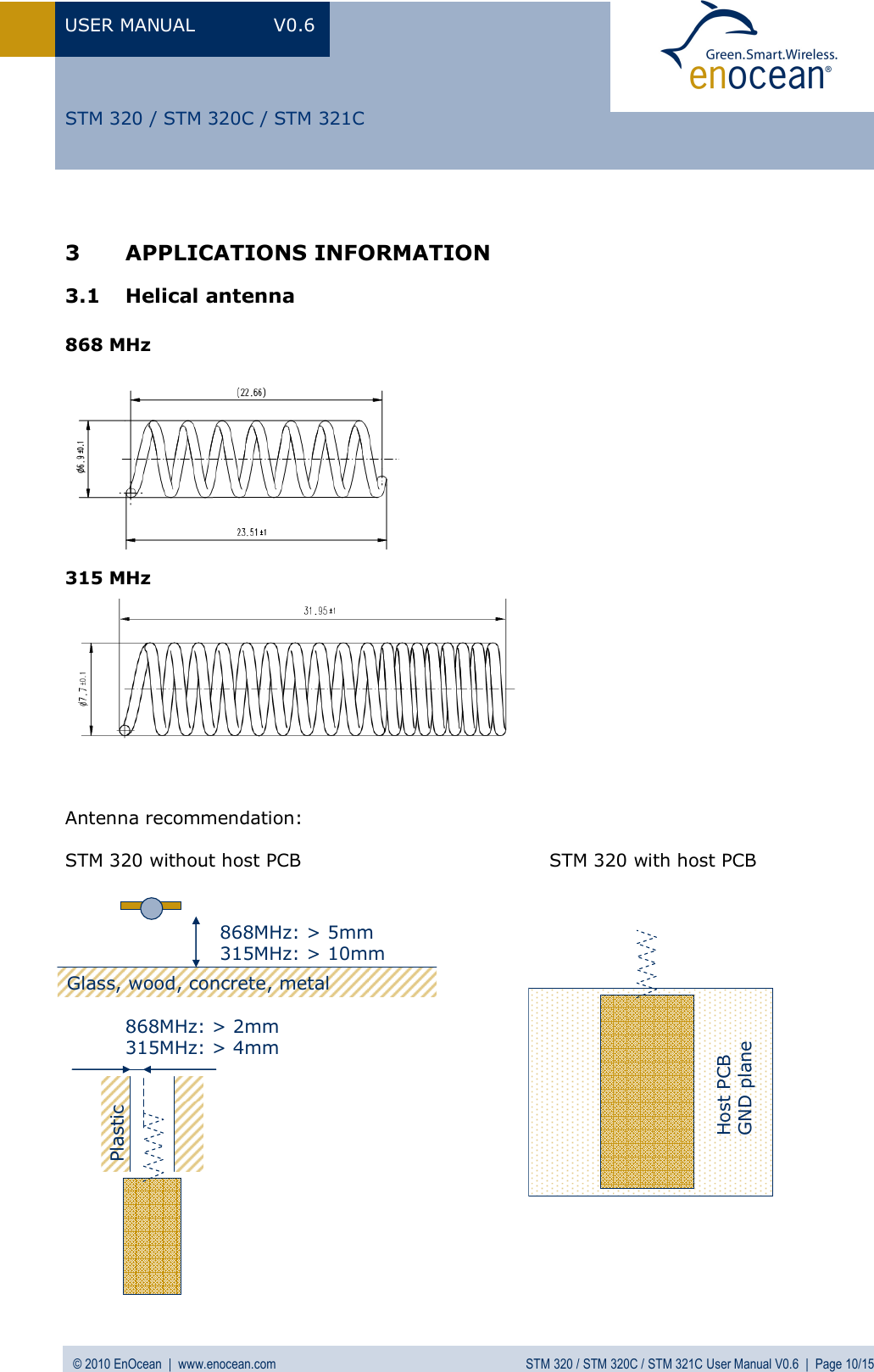
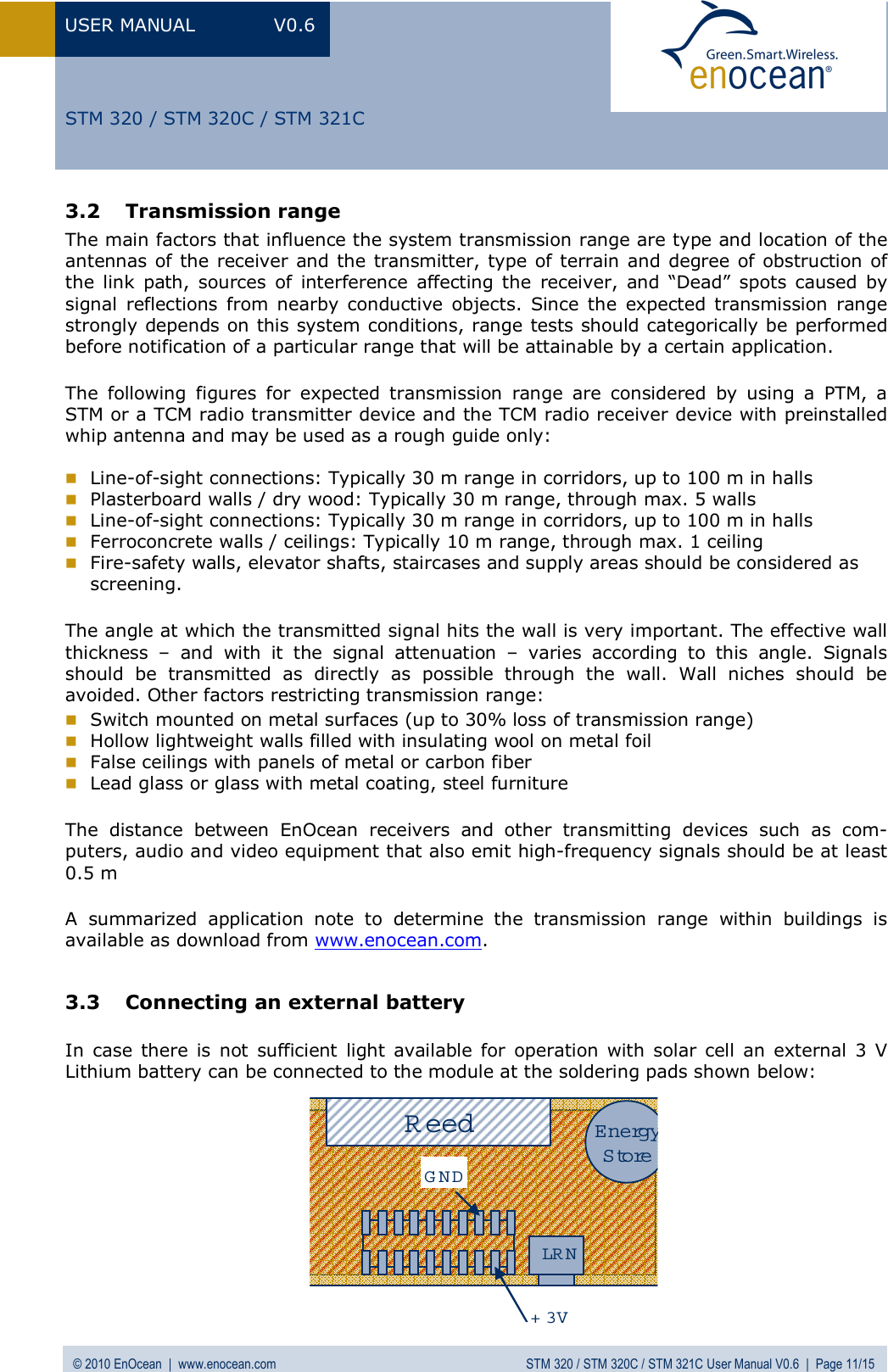
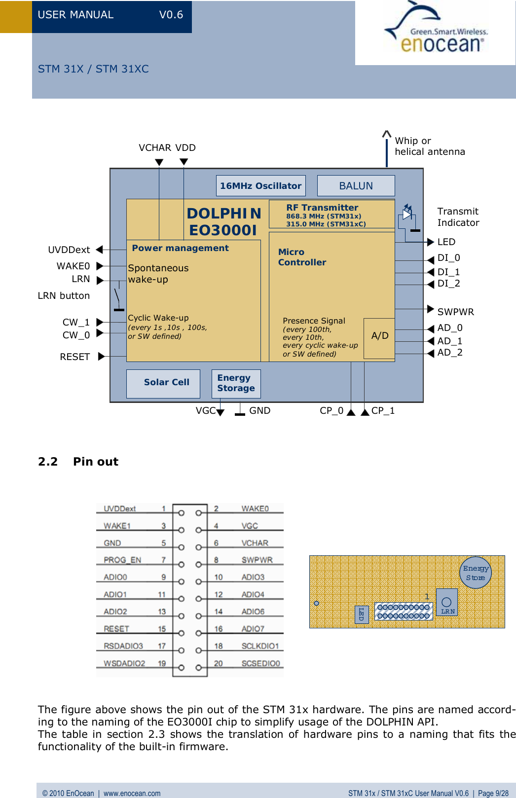
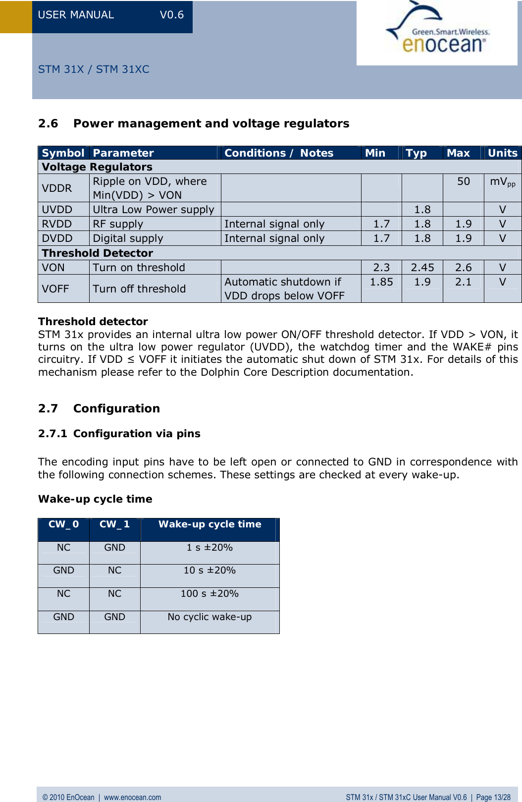
![USER MANUAL V0.6 © 2010 EnOcean | www.enocean.com STM 320 / STM 320C / STM 321C User Manual V0.6 | Page 9/15 STM 320 / STM 320C / STM 321C 2.3 Transmit timing The setup of the transmission timing allows avoiding possible collisions with data packages of other EnOcean transmitters as well as disturbances from the environment. With each transmission cycle, 3 identical subtelegrams are transmitted within 40 ms. The transmis-sion of a subtelegram lasts approximately 1.2 ms. The delay between the three transmis-sion bursts is affected at random. 2.4 Energy consumption Charge needed for one measurement and transmit cycle: ~80 µC Charge needed for one measurement cycle without transmit: ~10 µC Calculations are performed on the basis of electric charges because of the internal linear voltage regulator of the module. Energy consumption varies with voltage of the energy storage while consumption of electric charge is constant. From these values the following performance parameters have been calculated: Wake and transmit cycle [s] Operation Time in darkness [h] when storage fully charged Required reload time [h] at 200 lux within 24 h for continuous operation 1500 175 1.8 Assumptions: Internal storage PAS614L-VL3 with 0.25 F, Umax=3.2 V, Umin=2.3 V, T=25 °C Consumption: Transmit cycle 80 µC, measurement cycle 10 µC Pre-installed solar cell ECS 300, operating values 3 V and 5 µA @ 200 lux fluorescent light Current proportional to illumination level (not true at very low levels!) These values are calculated values, the accuracy is about +/-20%! 0.000010.00010.0010.010.11101000 102030405060708090100Time [ms]C urrent [mA]](https://usermanual.wiki/EnOcean/STM311C/User-Guide-1349384-Page-37.png)