EnOcean STM332U 902.875MHz transmitter User Manual unsers manual
EnOcean GmbH 902.875MHz transmitter unsers manual
UserManual.wiki
>
EnOcean
>
STM332U User Manual
unsers manual
Navigation menu
Upload a User Manual
Namespaces
Wiki Guide
HTML
PDF
Info
Views
User Manual
Discussion / Help
Navigation
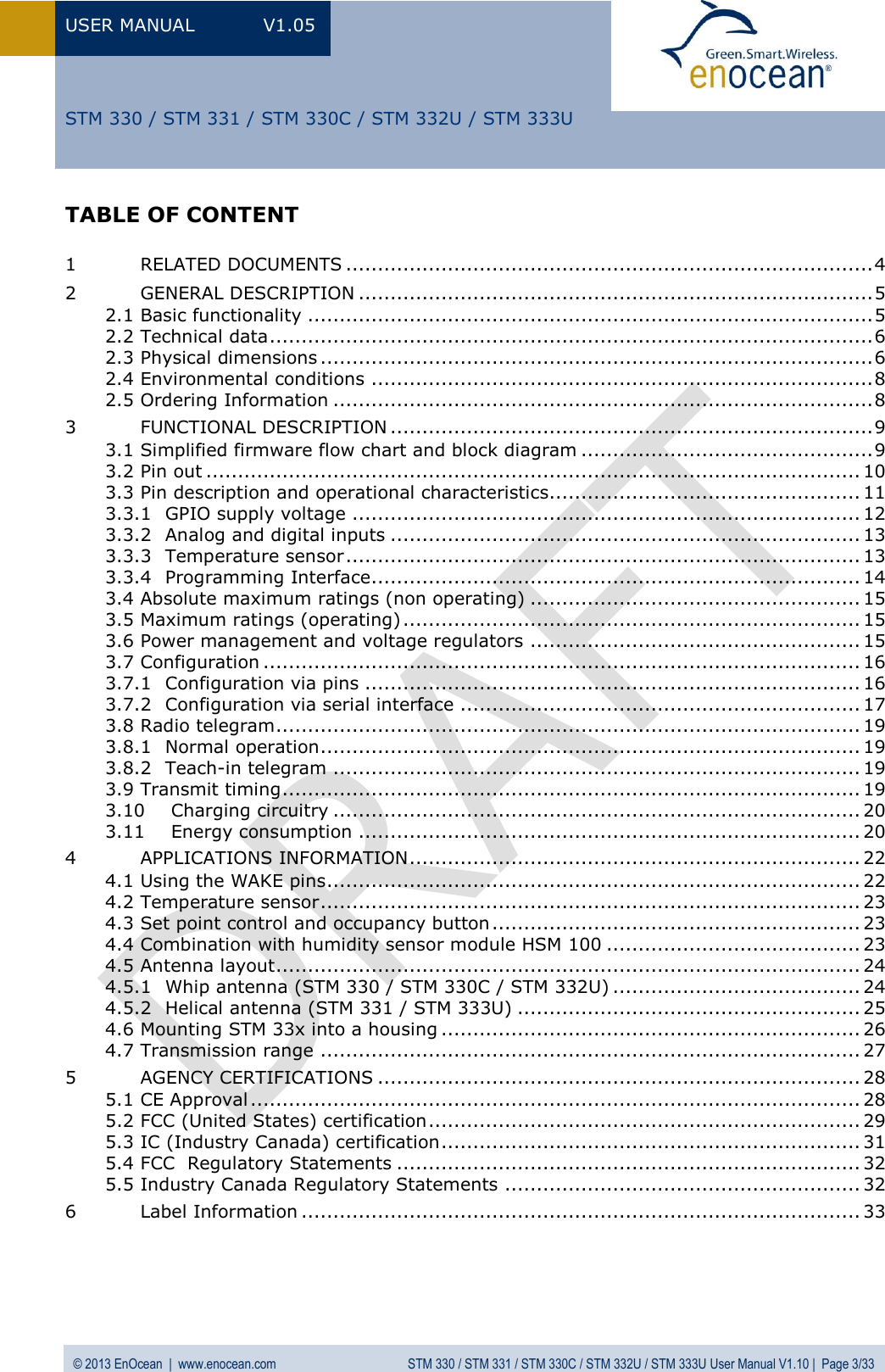
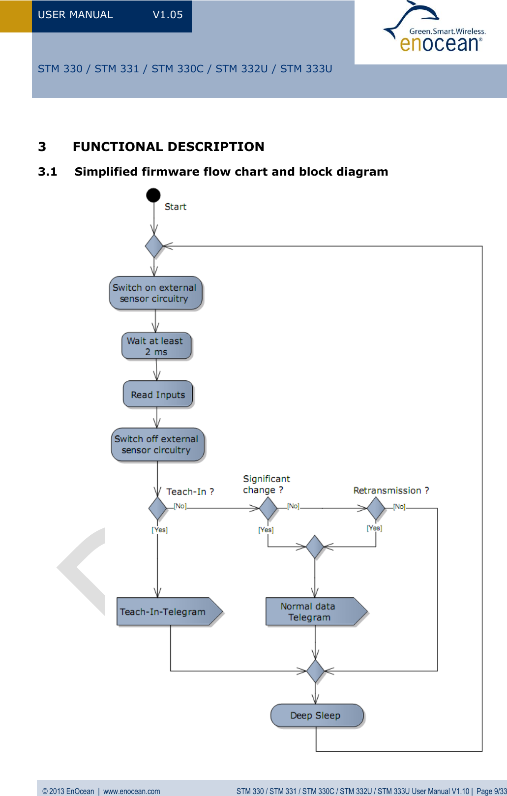
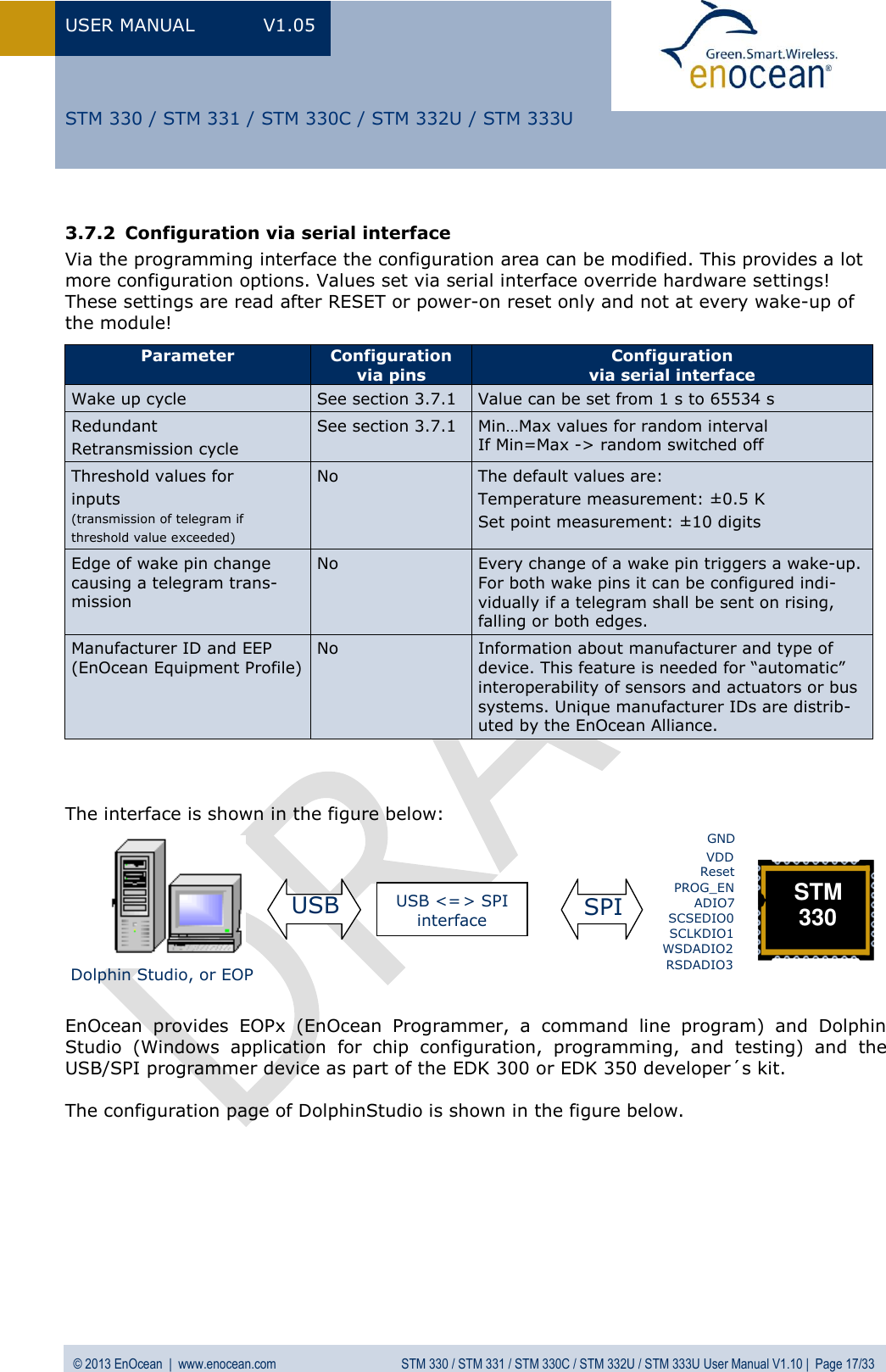
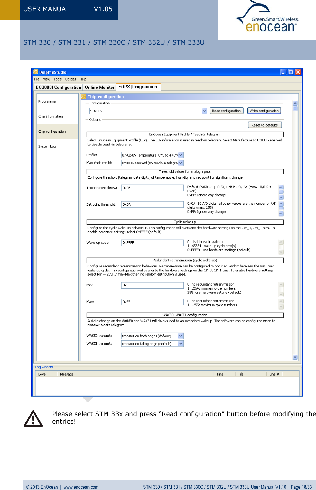
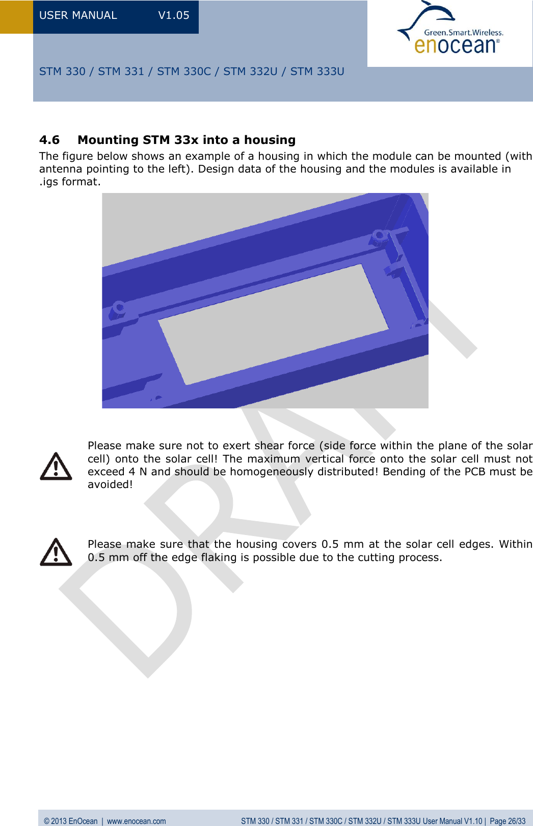
![USER MANUAL V1.05 © 2013 EnOcean | www.enocean.com STM 330 / STM 331 / STM 330C / STM 332U / STM 333U User Manual V1.10 | Page 20/33 STM 330 / STM 331 / STM 330C / STM 332U / STM 333U 3.10 Charging circuitry The figure below shows the internal charging circuit. It is controlled via the WXODIO pin of EO3000I which switches according to the status of the internal threshold detector. For de-tails please refer to our Dolphin Core Description documentation. The WXIDIO pin is used to disconnect the goldcap at voltages below VOFF to avoid deep discharge. An external 3 V backup battery can be connected at VCHAR. 3.11 Energy consumption Current Consumption of STM 33x Charge needed for one measurement and transmit cycle: ~130 µC Charge needed for one measurement cycle without transmit: ~30 µC (current for external sensor circuits not included) 0.000010.00010.0010.010.1110100010 20 30 40 50 60 70 80 90 100Time [ms]Current [mA]](https://usermanual.wiki/EnOcean/STM332U/User-Guide-1997286-Page-20.png)
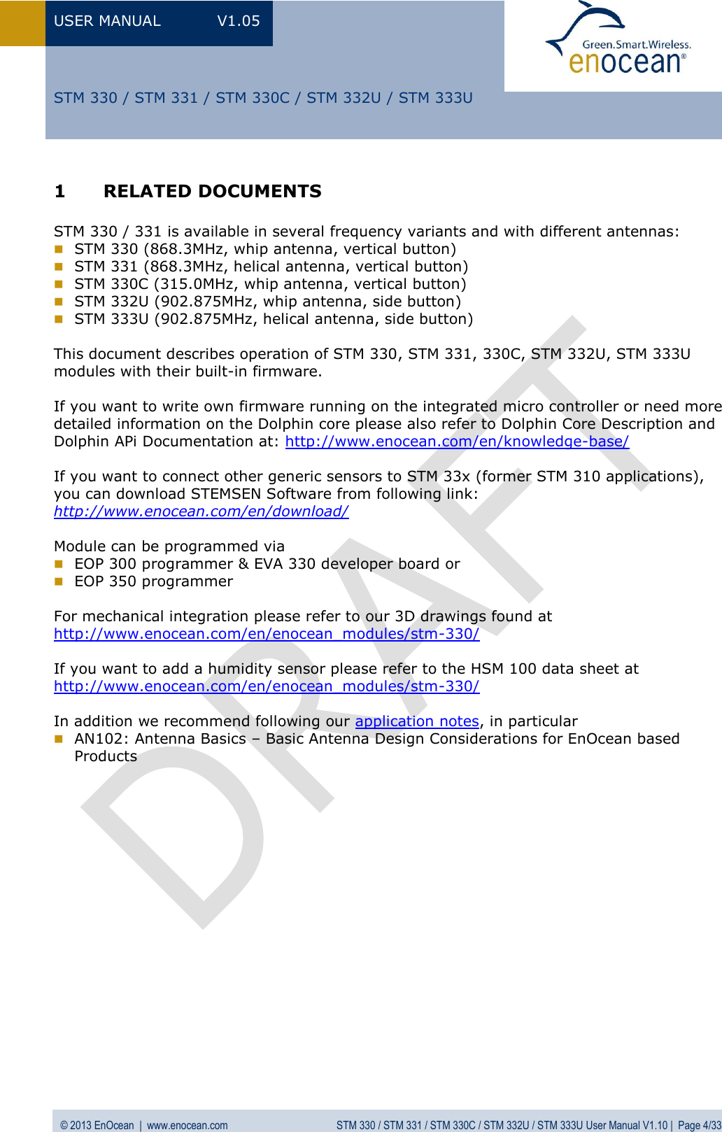
![USER MANUAL V1.05 © 2013 EnOcean | www.enocean.com STM 330 / STM 331 / STM 330C / STM 332U / STM 333U User Manual V1.10 | Page 21/33 STM 330 / STM 331 / STM 330C / STM 332U / STM 333U Calculations are performed on the basis of electric charges because of the internal linear voltage regulator of the module. Energy consumption varies with voltage of the energy storage while consumption of electric charge is constant. From these values the following typical performance parameters at room temperature have been calculated: Wake cycle [s] Transmit interval Operation Time in darkness [h] when storage fully charged Required reload time [h] at 200 lux within 24 h for continuous operation 24 h operation after 6 h illumination at x lux Illumina-tion level in lux for continuous operation Current in µA required for con-tinuous operation 1 1 0.5 storage too small storage too small 5220 130.5 1 10 1.7 storage too small storage too small 1620 40.5 1 100 2.1 storage too small storage too small 1250 31.3 10 1 5.1 storage too small storage too small 540 13.5 10 10 16 21 storage too small 175 4.4 10 100 20 16.8 storage too small 140 3.5 100 1 43 7.8 260 65 1.6 100 10 98 3.6 120 30 0.8 100 100 112 3 100 25 0.6 Assumptions: Internal storage PAS614L-VL3 (after several days of operation at good illumination level) with 0.25 F, Umax=3.2 V, Umin=2.2 V, T=25 °C Consumption: Transmit cycle 100 µC, measurement cycle 30 µC Pre-installed solar cell ECS 300, operating values 3 V and 5 µA @ 200 lux fluorescent light Current proportional to illumination level (not true at very low levels!) These values are calculated, the accuracy is about +/-20%! The performance varies over temperature and may be strongly reduced at extreme temperatures or short transmit inter-vals.](https://usermanual.wiki/EnOcean/STM332U/User-Guide-1997286-Page-21.png)