EnOcean TCM515Z 2.4 GHz IEEE 802.15.4 Transceiver User Manual
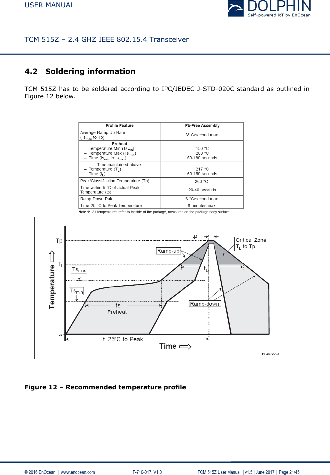
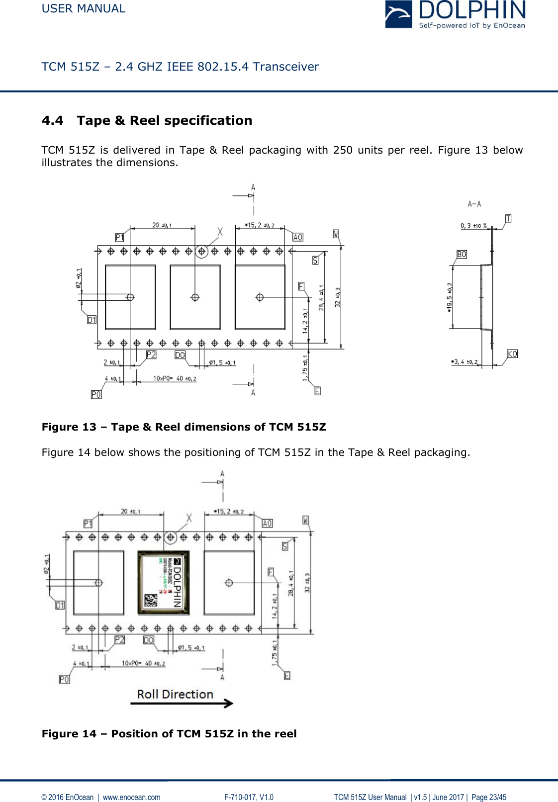
EnOcean GmbH 2.4 GHz IEEE 802.15.4 Transceiver
UserManual.wiki
>
EnOcean
>
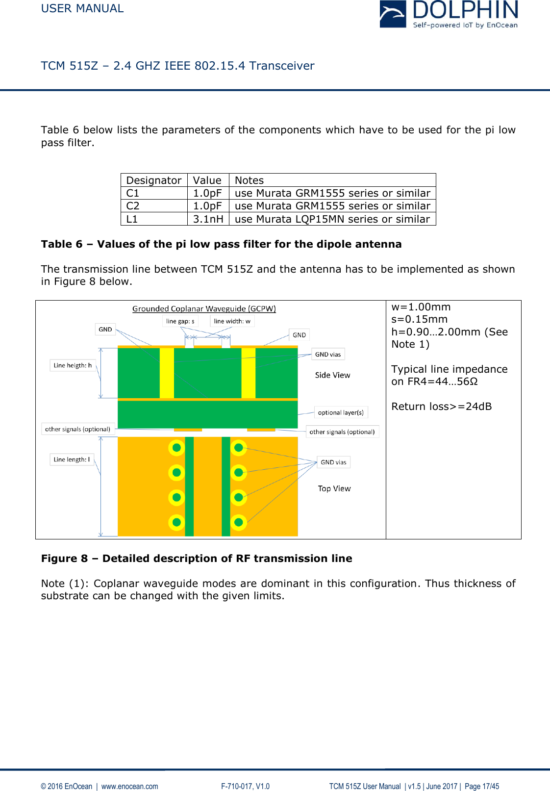
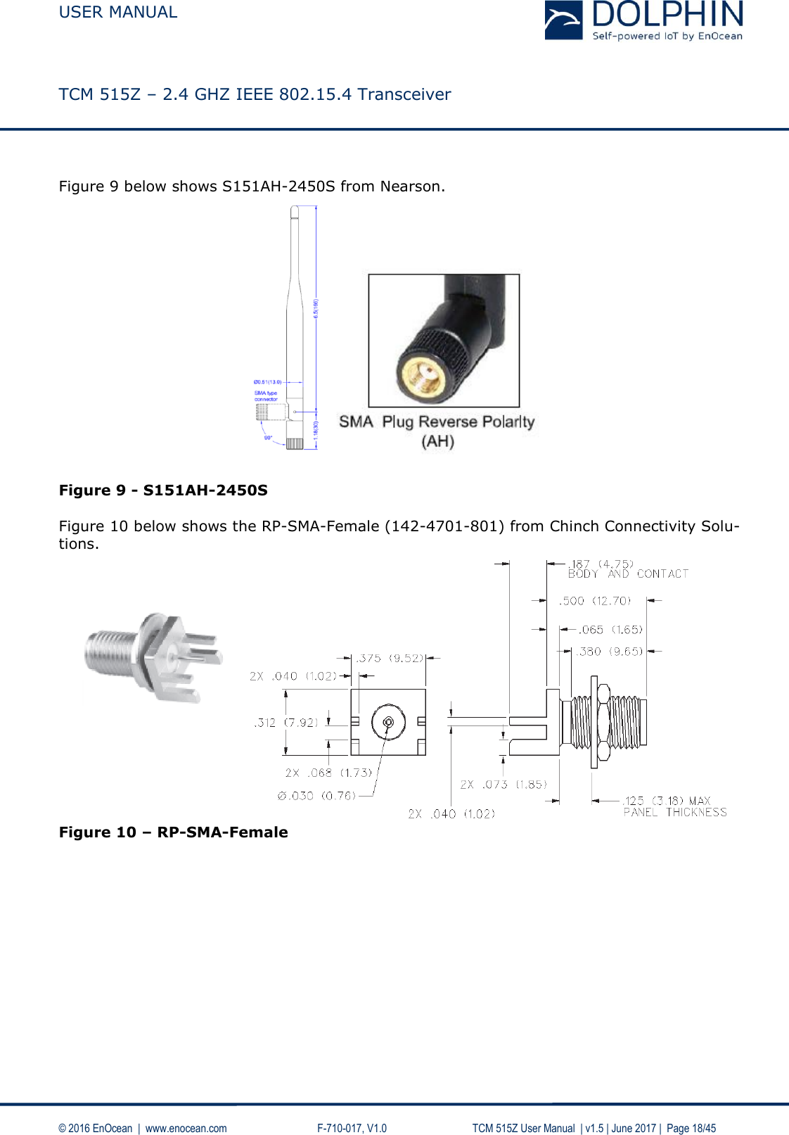
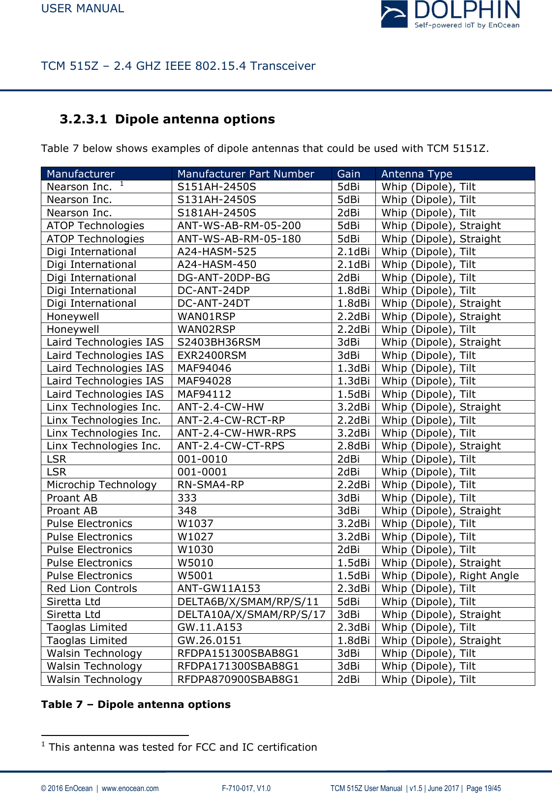
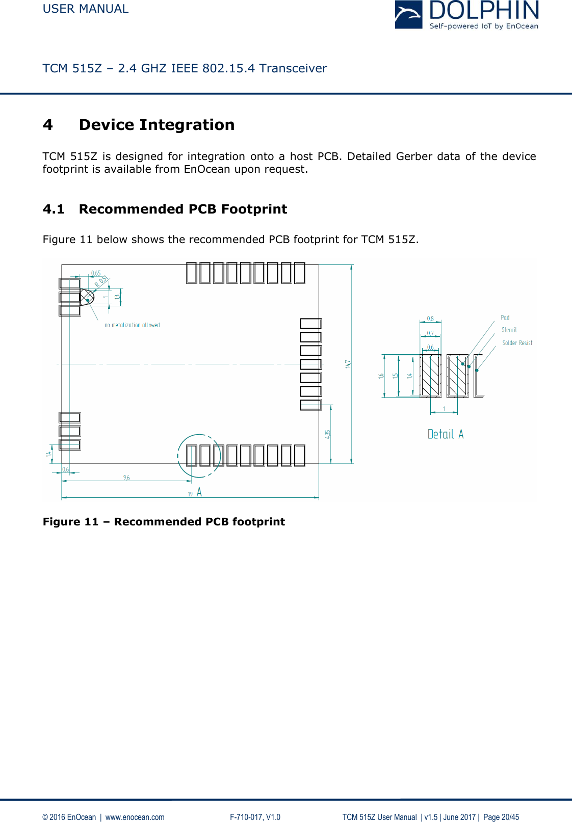
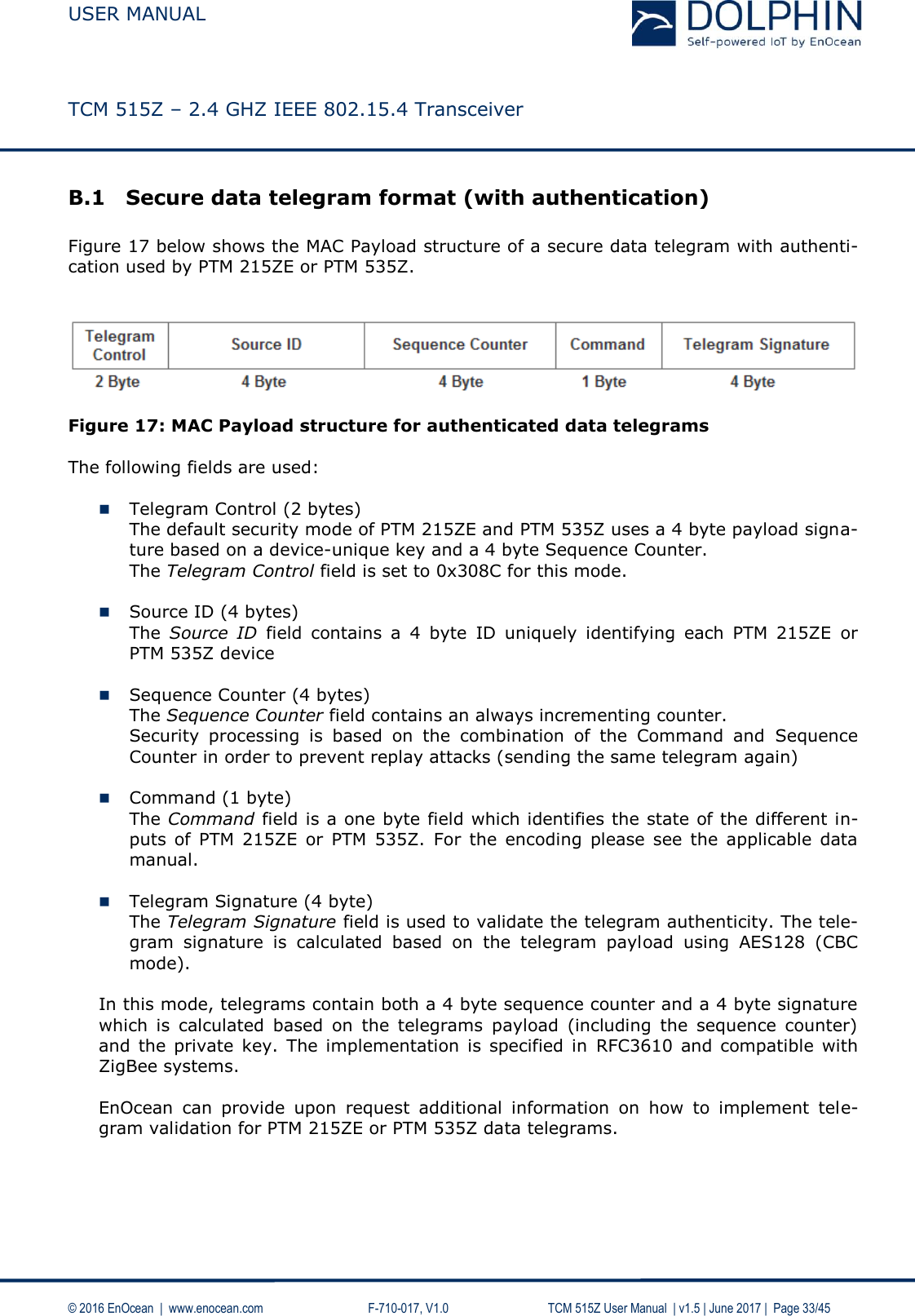
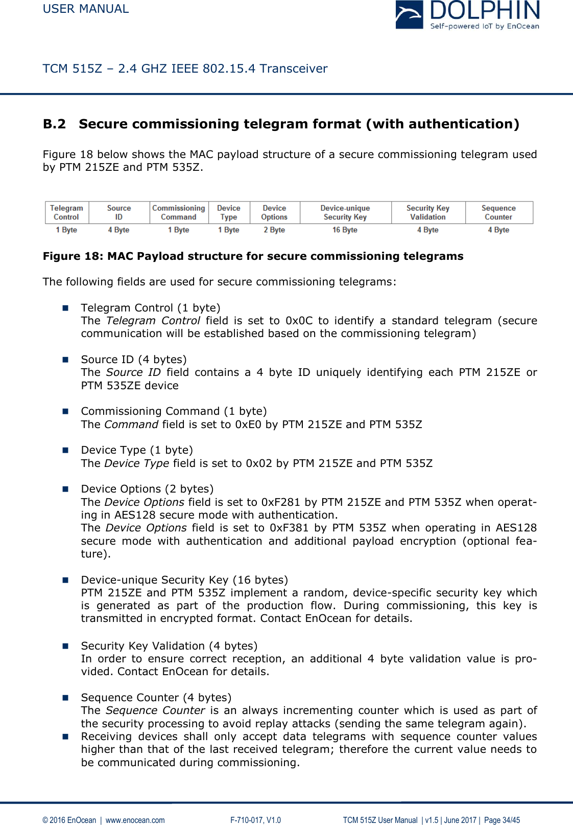
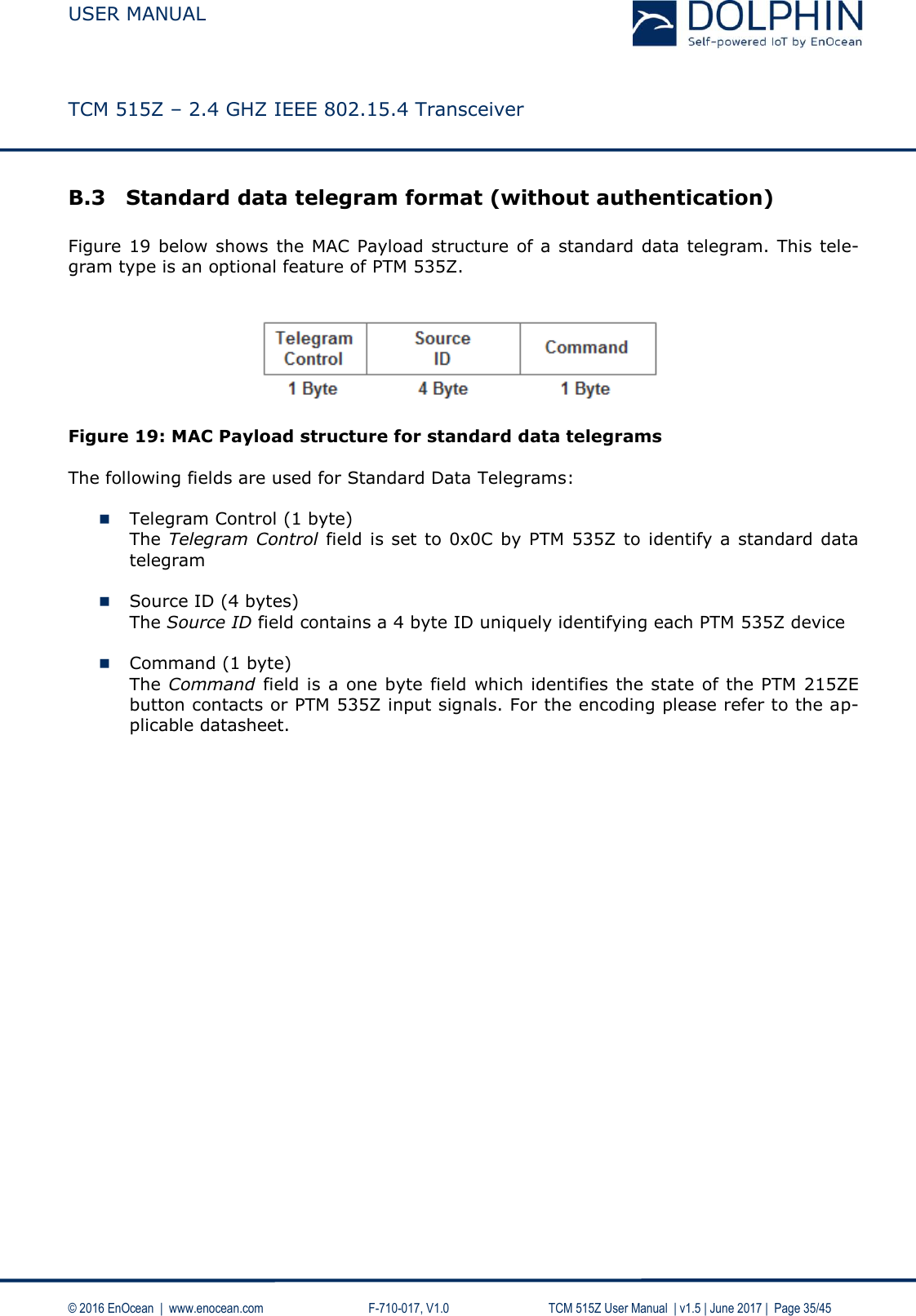
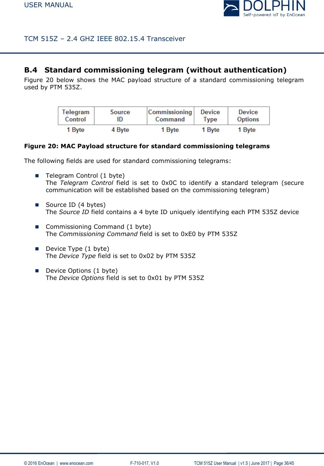
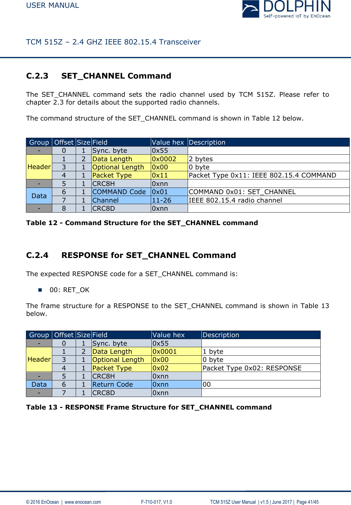
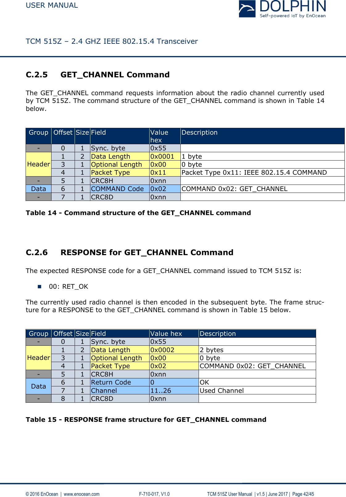
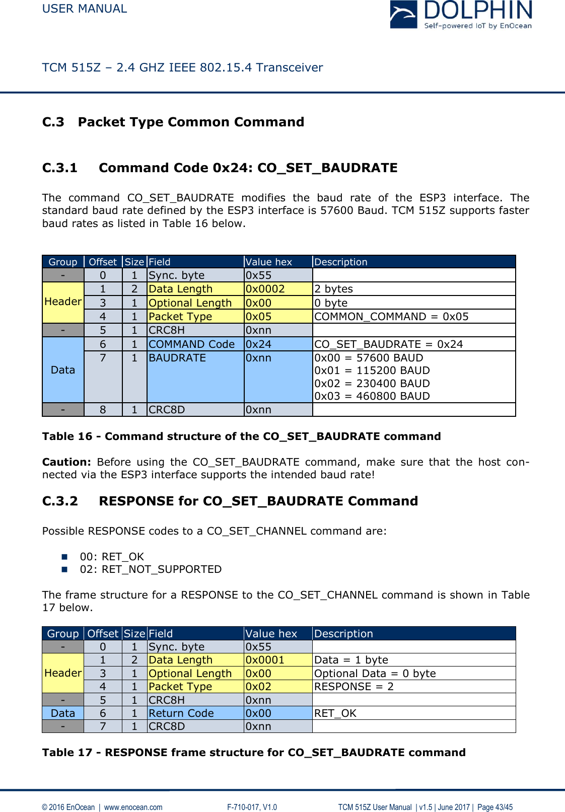
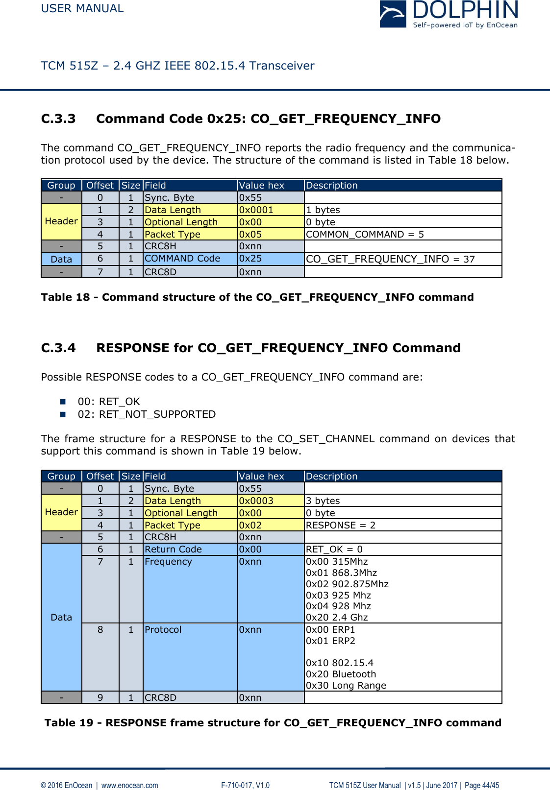
TCM515Z User Manual
User Manual
Navigation menu
Upload a User Manual
Namespaces
Wiki Guide
HTML
PDF
Info
Views
User Manual
Discussion / Help
Navigation