EnOcean TCM515Z 2.4 GHz IEEE 802.15.4 Transceiver User Manual
EnOcean GmbH 2.4 GHz IEEE 802.15.4 Transceiver
EnOcean >
User Manual

USER MANUAL
TCM 515Z – 2.4 GHZ IEEE 802.15.4 Transceiver
© 2016 EnOcean | www.enocean.com F-710-017, V1.0 TCM 515Z User Manual | v1.5 | June 2017 | Page 1/45
Patent protected:
WO98/36395, DE 100 25 561, DE 101 50 128,
WO 2004/051591, DE 103 01 678 A1, DE 10309334,
WO 04/109236, WO 05/096482, WO 02/095707,
US 6,747,573, US 7,019,241
Observe precautions! Electrostatic sensitive devices!
12 June 2017

USER MANUAL
TCM 515Z – 2.4 GHZ IEEE 802.15.4 Transceiver
© 2016 EnOcean | www.enocean.com F-710-017, V1.0 TCM 515Z User Manual | v1.5 | June 2017 | Page 2/45
REVISION HISTORY
The following major modifications and improvements have been made to this document:
Version
Author
Reviewer
Date
Major Changes
1.0
MKA
MK, MF
01.03.2016
Initial Release
1.1
MKA
MKA
01.05.2016
Added protocol description, changed location of
TURBO Pin
1.2
MKA
MKA
19.07.2016
Added reflow profile
1.3
MKA
MKA
23.01.2017
Added list of supported ESP3 commands and
minimum values for sensitivity and output power
1.4
MKA
MKA
13.02.2017
Added additional ESP3 interface speeds, added
caution note regarding switching to TURBO mode
via ESP3 command
1.5
MKA
MKA
12.06.2017
Added information about antenna options for US
(FCC regulation)
1.6
DL
20.07.2017
Added information about FCC labelling require-
ments
1.7
DL
21.08.2017
Added information about RF expose and distance
requirements
Published by EnOcean GmbH, Kolpingring 18a, 82041 Oberhaching, Germany
www.enocean.com, info@enocean.com, phone +49 (89) 6734 6890
© EnOcean GmbH, All Rights Reserved
Important!
This information describes the type of component and shall not be considered as assured
characteristics. No responsibility is assumed for possible omissions or inaccuracies. Circuitry
and specifications are subject to change without notice. For the latest product specifica-
tions, refer to the EnOcean website: http://www.enocean.com.
As far as patents or other rights of third parties are concerned, liability is only assumed for
modules, not for the described applications, processes and circuits.
EnOcean does not assume responsibility for use of modules described and limits its liability
to the replacement of modules determined to be defective due to workmanship. Devices or
systems containing RF components must meet the essential requirements of the local legal
authorities.
The modules must not be used in any relation with equipment that supports, directly or
indirectly, human health or life or with applications that can result in danger for people,
animals or real value.
Components of the modules are considered and should be disposed of as hazardous waste.
Local government regulations are to be observed.
Packing: Please use the recycling operators known to you.

USER MANUAL
TCM 515Z – 2.4 GHZ IEEE 802.15.4 Transceiver
© 2016 EnOcean | www.enocean.com F-710-017, V1.0 TCM 515Z User Manual | v1.5 | June 2017 | Page 3/45
TABLE OF CONTENT
1 GENERAL DESCRIPTION ................................................................................. 5
1.1 Basic functionality ......................................................................................... 5
1.2 Technical data ............................................................................................... 6
1.3 Physical dimensions ....................................................................................... 6
1.4 Environmental conditions ............................................................................... 6
1.5 Packaging information .................................................................................... 6
1.6 Ordering information ..................................................................................... 6
2 FUNCTIONAL INFORMATION ........................................................................... 7
2.1 TCM 515Z Device Interface ............................................................................. 7
2.1.1 Signal Description .................................................................................. 8
2.2 High-level operation principle .......................................................................... 8
2.3 Supported Radio Channels .............................................................................. 9
2.4 ESP3 Interface ............................................................................................ 10
2.4.1 ESP3 Data Format................................................................................ 10
2.4.2 Supported ESP3 Commands .................................................................. 10
3 Antenna options .......................................................................................... 11
3.1 Antenna options for European Union .............................................................. 11
3.1.1 General requirements ........................................................................... 11
3.1.2 Whip antenna ...................................................................................... 12
3.2 Antenna options for US / Canada ................................................................... 13
3.2.1 Whip antenna ...................................................................................... 13
3.2.2 Meandered PCB antenna ....................................................................... 15
3.2.3 Dipole antenna .................................................................................... 16
3.2.3.1 Dipole antenna options ...................................................................... 19
4 Device Integration ....................................................................................... 20
4.1 Recommended PCB Footprint ........................................................................ 20
4.2 Soldering information .................................................................................. 21
4.3 Device handling instructions ......................................................................... 22
4.4 Tape & Reel specification .............................................................................. 23
5 APPLICATION INFORMATION ........................................................................ 24
5.1 Transmission range ..................................................................................... 24
6 REGULATORY INFORMATION......................................................................... 25
6.1 CE (RED) for European Union ........................................................................ 25
6.2 FCC (United States) Certificate ...................................................................... 26
6.2.1 FCC (United States) Regulatory Statement .............................................. 27
6.2.2 FCC (United States) Labeling Requirements ............................................ 27
6.2.3 FCC (United States) RF Expose .............................................................. 27
6.3 IC (Industry Canada) Certificate .................................................................... 28
6.3.1 IC (Industry Canada) Regulatory Statement ............................................ 28
6.3.2 IC (Industry Canada) RF Expose ............................................................ 28
Appendix A IEEE 802.15.4 Frame Structure ............................................................. 29

USER MANUAL
TCM 515Z – 2.4 GHZ IEEE 802.15.4 Transceiver
© 2016 EnOcean | www.enocean.com F-710-017, V1.0 TCM 515Z User Manual | v1.5 | June 2017 | Page 4/45
A.1 IEEE 802.15.4 High Level Frame Structure ..................................................... 29
A.2 PHY Header ................................................................................................ 30
A.2.1 Length of Frame values used by PTM 215ZE and PTM 535Z .......................... 30
A.3 MAC Header ................................................................................................ 31
A.4 MAC Payload ............................................................................................... 31
A.5 MAC Trailer ................................................................................................. 31
Appendix B MAC Payload Structure ......................................................................... 32
B.1 Secure data telegram format (with authentication) .......................................... 33
B.2 Secure commissioning telegram format (with authentication) ........................... 34
B.3 Standard data telegram format (without authentication) .................................. 35
B.4 Standard commissioning telegram (without authentication) .............................. 36
Appendix C ESP3 Interface Format ......................................................................... 37
C.1 Packet Type 0x10: IEEE 802.15.4 Raw Packet ................................................. 37
C.1.1 ESP3 packet structure for IEEE 802.15.4 Raw Packets .................................. 37
C.1.2 RESPONSE for IEEE 802.15.4 Raw Packets ................................................. 38
C.1.3 Failure Indication for IEEE 802.15.4 Raw Packet .......................................... 39
C.2 Packet Type 0x11: IEEE 802.15.4 COMMAND .................................................. 40
C.2.1 Packet structure for IEEE 802.15.4 COMMAND ............................................ 40
C.2.2 List of supported commands ..................................................................... 40
C.2.3 SET_CHANNEL Command ......................................................................... 41
C.2.4 RESPONSE for SET_CHANNEL Command .................................................... 41
C.2.5 GET_CHANNEL Command ......................................................................... 42
C.2.6 RESPONSE for GET_CHANNEL Command .................................................... 42
C.3 Packet Type Common Command ................................................................... 43
C.3.1 Command Code 0x24: CO_SET_BAUDRATE ................................................ 43
C.3.2 RESPONSE for CO_SET_BAUDRATE Command ............................................ 43
C.3.3 Command Code 0x25: CO_GET_FREQUENCY_INFO ..................................... 44
C.3.4 RESPONSE for CO_GET_FREQUENCY_INFO Command .................................. 44
C.3.5 Command Code 37: CO_GET_STEPCODE.................................................... 45
C.3.6 RESPONSE for CO_GET_STEPCODE Command ............................................ 45
USER MANUAL
TCM 515Z – 2.4 GHZ IEEE 802.15.4 Transceiver
© 2016 EnOcean | www.enocean.com F-710-017, V1.0 TCM 515Z User Manual | v1.5 | June 2017 | Page 5/45
1 GENERAL DESCRIPTION
1.1 Basic functionality
TCM 515Z enables the realization of line-powered actuators, controllers and gateways
communicating based on the 2.4 GHz IEEE 802.15.4 radio standard. It provides a transpar-
ent radio link between EnOcean 2.4 GHz devices and an external host connected via the
standardized ESP3 interface (EnOcean Serial Protocol, version 3).
TCM 515Z receives and transmits radio telegrams based on a 50 Ohm or whip antenna
connected to the host PCB. It forwards received 2.4 GHz IEEE 802.15.4 radio telegrams
to an external host processor or host PC via the ESP3 interface.
IEEE 802.15.4 messages received from an external host via the ESP3 interface will be
transmitted by TCM 515Z as 2.4 GHz radio telegrams.
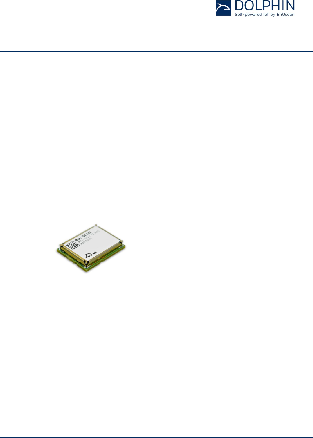
TCM 515Z is implemented as 31 pin reflow-solderable module with optimized form factor
for size constrained applications.
Figure 1 below shows TCM 515Z.
Figure 1 – TCM 515Z outline

USER MANUAL
TCM 515Z – 2.4 GHZ IEEE 802.15.4 Transceiver
© 2016 EnOcean | www.enocean.com F-710-017, V1.0 TCM 515Z User Manual | v1.5 | June 2017 | Page 6/45
1.2 Technical data
Antenna
External 50 Ohm or whip antenna (connected at host board)
Supported Radio Frequency Range
Radio channel 11 … 26 according to IEEE 802.15.4 standard
Default Radio Channel
IEEE 802.15.4 radio channel 11
Receiver Sensitivity (at 25°C)(1)
Minimum: -92dBm / Typical: –95 dBm
Transmit Power (at 25°C)
Minimum: 0dBm / Typical: +2 dBm
Power Supply
3.3 V +- 10%
Serial Host Interface
UART according to ESP3 Standard with Turbo Mode Option
Current Consumption (typ, at 25°C)
Transmit: 20mA, Receive: 15 mA
Radio Regulation
R&TTE (Europe), FCC (US), IC (Canada)
Note (1): Receiver sensitivity is based on the combination of 3 subtelegrams
1.3 Physical dimensions
Module Dimensions
19.0 x 14.7 x 3.0 mm (each dimension +-0.3 mm)
Module Weight
1 g
1.4 Environmental conditions
Operating Temperature
-25°C ... 85°C
Storage Temperature
-25°C ... 85°C
Humidity
0% to 95% r.h. (non-condensing)
1.5 Packaging information
Packaging Unit 250 units
Packaging Method Tape and reel
1.6 Ordering information
Type
Ordering Code
Frequency
TCM 515Z
S3073-K515
2.4 GHz (IEEE 802.15.4)
USER MANUAL
TCM 515Z – 2.4 GHZ IEEE 802.15.4 Transceiver
© 2016 EnOcean | www.enocean.com F-710-017, V1.0 TCM 515Z User Manual | v1.5 | June 2017 | Page 7/45
2 FUNCTIONAL INFORMATION
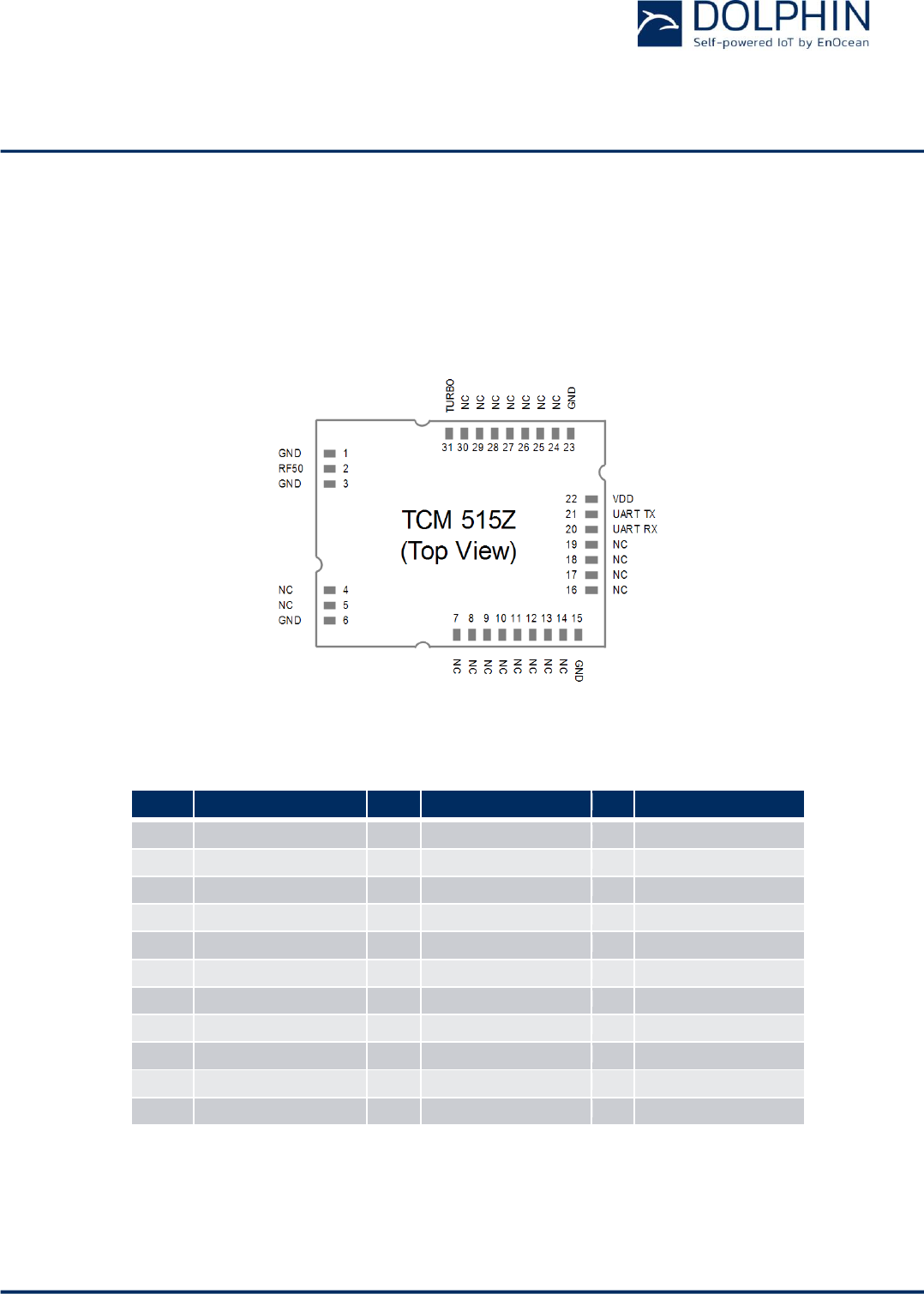
2.1 TCM 515Z Device Interface
TCM 515Z implements a 31 pin reflow-solderable interface. Solder mask data is available
on request from EnOcean. The pin assignment (as seen from the top of the device) is
shown in Figure 2 below.
Figure 2 – TCM 515Z device interface
Table 1 below summarizes the signal assignment.
PIN
NAME
PIN
NAME
PIN
NAME
1
GND
12
NC
23
GND
2
ANTENNA (50 Ohms)
13
NC
24
NC
3
GND
14
NC
25
NC
4
NC
15
GND
26
NC
5
NC
16
NC
27
NC
6
GND
17
NC
28
NC
7
NC
18
NC
29
NC
8
NC
19
NC
30
NC
9
NC
20
UART_RX (Input)
31
TURBO
10
NC
21
UART_TX (Output)
11
NC
22
VDD
Table 1 - TCM 5151Z device interface pin assignment
Signals marked with “NC” are reserved for production test and future device variants and
must not be connected in the design.

USER MANUAL
TCM 515Z – 2.4 GHZ IEEE 802.15.4 Transceiver
© 2016 EnOcean | www.enocean.com F-710-017, V1.0 TCM 515Z User Manual | v1.5 | June 2017 | Page 8/45
2.1.1 Signal Description
TCM 515Z is supplied by the VDD and GND Pins. The required supply voltage is 3.3V with a
tolerance of no more than +-10%.
TCM 515Z receives and transmits data based on a 50Ω whip antenna connected to its AN-
TENNA input (Pin 2).
TCM 515Z communicates with the external host using the standard ESP3 serial (UART) in-
terface based on the signals UART_TX (Pin 21, direction from TCM 515Z to external host)
and UART_RX (Pin 20, direction from external host to TCM 51Z).
The default interface speed of the ESP3 interface is 57600 bit per second (the exact speed
is 57347 Bit per second, a deviation of -0.04%).
It is possible to select faster communication speeds of 115200, 230400 and 460800 bit per
second during operation using the CO_SET_BAUDRATE command as shown in Table 16.
Additionally it is possible to change the default ESP3 interface speed at power up from
57.600 Bit per second to 460.800 Bit per second by connecting the TURBO input (Pin 31) to
Ground. Subsequent modification of the interface speed during operation using the
CO_SET_BAUDRATE command is always possible irrespective of the state of the TURBO
input pin.
2.2 High-level operation principle
In receive mode, TCM 515Z forwards the content of received IEEE 802.15.4 radio telegrams
(which pass frame check sum validation) unmodified to the external host via the ESP3 in-
terface.
The forwarded frame starts with the Length field of the IEEE 802.15.4 PHY Header, contin-
ues with the MAC Header and ends with the last Byte of the MAC Payload. The frame check
sum (MAC Trailer) will not be forwarded to the host.
In transmit mode, TCM 515Z receives from the external host the precomputed message
payload starting with the Length field of the IEEE 802.15.4 PHY Header, continuing with the
MAC Header and ending with the last Byte of the MAC Payload.
TCM 515Z then calculates the frame check sum (MAC Trailer) and appends it to the mes-
sage. The full frame (including the Preamble and Start of Frame fields) will then be trans-
mitted as IEEE 802.15.4 radio telegram (TX mode).
USER MANUAL
TCM 515Z – 2.4 GHZ IEEE 802.15.4 Transceiver
© 2016 EnOcean | www.enocean.com F-710-017, V1.0 TCM 515Z User Manual | v1.5 | June 2017 | Page 9/45
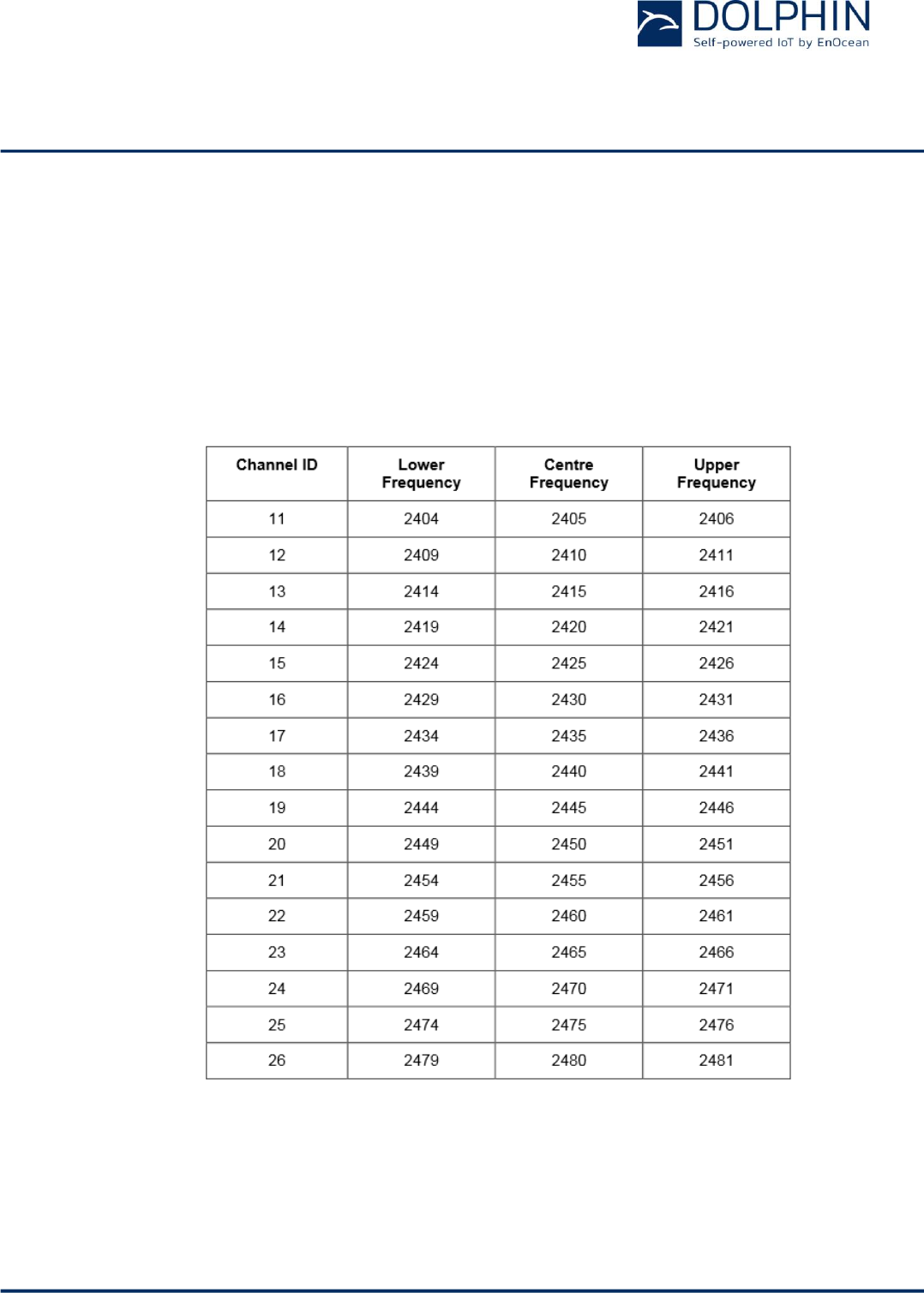
2.3 Supported Radio Channels
TCM 515Z support all radio channels of the IEEE 802.15.4 standard in the 2.4 GHz band.
The radio channel used by TCM 515Z can be set by an external host using the ESP3
SET_CHANNEL command as described in Appendix C.2.3.
The channel notation used by TCM 515Z follows IEEE 802.15.4 standard, i.e. channel 11 is
the first channel (lowest frequency) and channel 26 is the last channel (highest frequency).
Table 2 below shows the correspondence between channel ID and channel frequency.
Table 2 - Supported radio channels

USER MANUAL
TCM 515Z – 2.4 GHZ IEEE 802.15.4 Transceiver
© 2016 EnOcean | www.enocean.com F-710-017, V1.0 TCM 515Z User Manual | v1.5 | June 2017 | Page 10/45
2.4 ESP3 Interface
TCM 515Z provides a bi-directional UART interface for communicating with the external
host. The default baud rate of this interface is 57600 bps. If the TURBO pin is set to active
low then the baud rate is increased to 460.800 bps.
2.4.1 ESP3 Data Format
TCM 515Z communicate with external hosts using EnOcean Serial Protocol version 3 (ESP3)
with EnOcean 2.4 GHz IEEE 802.15.4 extensions.
Please consult the detailed ESP3 specification at https://www.enocean.com/esp.
2.4.2 Supported ESP3 Commands
TCM 515Z supports the following ESP3 commands:
Packet Type 0x10: IEEE 802.15.4 Raw Packet
Packet Type 0x11: IEEE 802.15.4 COMMAND
o SET_CHANNEL
o GET_CHANNEL
Packet Type 0x05: Common Command
o CO_SET_BAUDRATE
o CO_GET_FREQUENCY_INFO
o CO_GET_STEPCODE
Please refer to Appendix C for a description of the supported commands.

USER MANUAL
TCM 515Z – 2.4 GHZ IEEE 802.15.4 Transceiver
© 2016 EnOcean | www.enocean.com F-710-017, V1.0 TCM 515Z User Manual | v1.5 | June 2017 | Page 11/45
3 Antenna options
This chapter outlines options for antenna that can be used with TCM 515Z. Note that this
chapter is for guidance purposes only, please consult with an authorized certification body
for specific information.
3.1 Antenna options for European Union
See chapter 6.1 for additional important remarks regarding RED certification.
3.1.1 General requirements
In order to be compliant with the Radio Equipment Directive (RED) of the European Union,
an antenna needs to fulfil the requirements listed in Table 3 below.
Frequency band
868.300 MHz ISM
Antenna must be suited for
this band
Antenna type
Passive
Mandatory for radio approval
Impedance
~50 Ohm
Mandatory for radio approval
Maximum gain
≤ 0 dBd
Mandatory for radio approval
Table 3 – Required antenna parameters for RED certification
In addition, it is important to fulfil the requirements listed in Table 4 below in order to
achieve good levels of EMI robustness.
VSWR
≤ 3:1
Important for compatibility
with EnOcean protocol
Return Loss
> 6 dB
Important for compatibility
with EnOcean protocol
Bandwidth
≤ 20 MHz
Important if 10 V/m EMI
robustness required for de-
vice
Table 4 – Required antenna parameters for EMI robustness
USER MANUAL
TCM 515Z – 2.4 GHZ IEEE 802.15.4 Transceiver
© 2016 EnOcean | www.enocean.com F-710-017, V1.0 TCM 515Z User Manual | v1.5 | June 2017 | Page 12/45
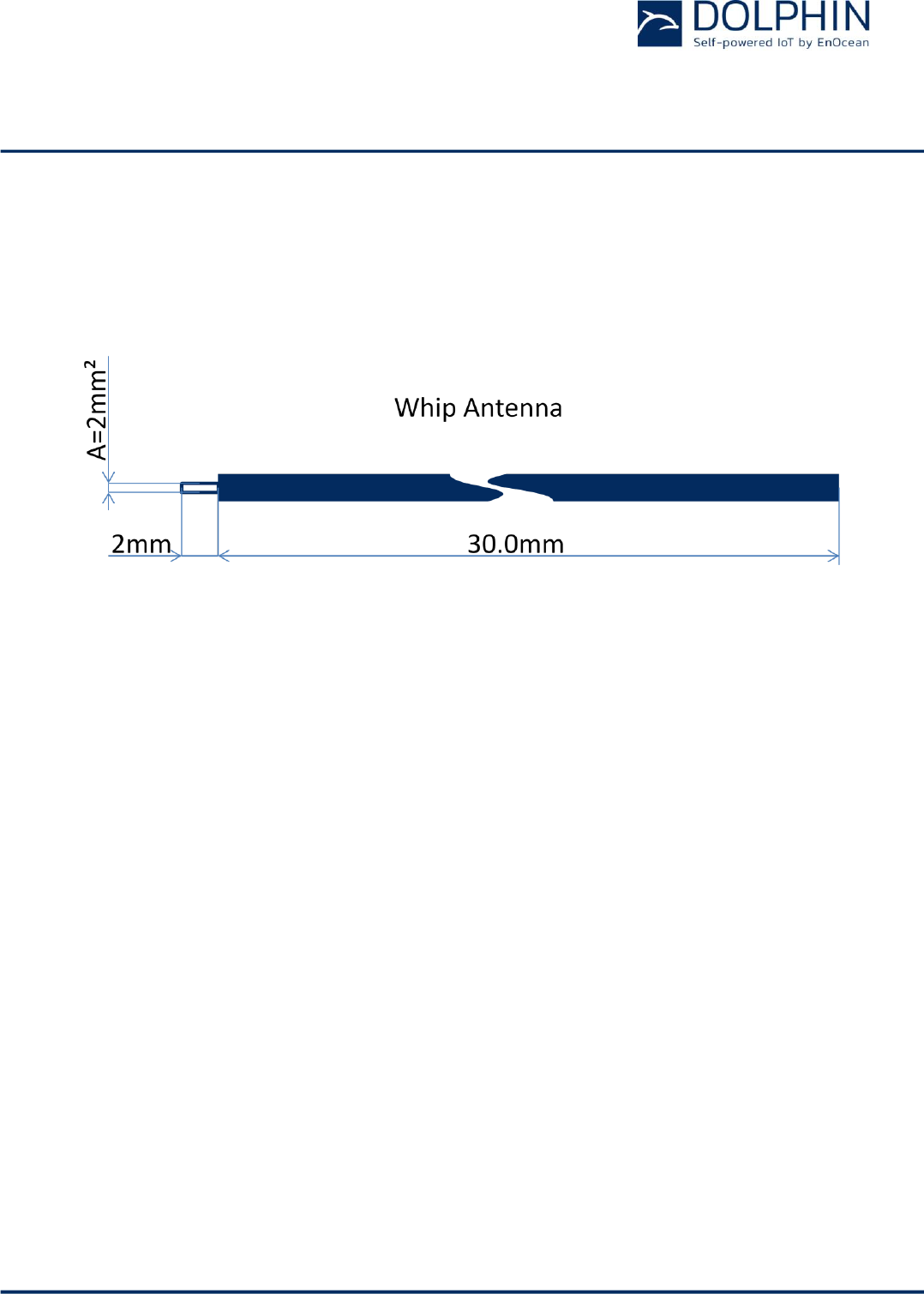
3.1.2 Whip antenna
TCM 515Z modules have been certified for use with a whip antenna under EU (RED) regula-
tions. Figure 3 below shows key whip antenna parameters.
Figure 3 – Whip antenna parameters for 2.4 GHz
The whip antenna has to meet the following parameters in order to be compliant with RED
regulation:
Antenna length (L): 30 mm wire, connect to RF_WHIP
Minimum GND plane: 15 mm x 15 mm
Minimum distance space: 10 mm
USER MANUAL
TCM 515Z – 2.4 GHZ IEEE 802.15.4 Transceiver
© 2016 EnOcean | www.enocean.com F-710-017, V1.0 TCM 515Z User Manual | v1.5 | June 2017 | Page 13/45
3.2 Antenna options for US / Canada
The TCM 515Z has been tested and certified according to FCC regulation with a number of
different antennas as described below.
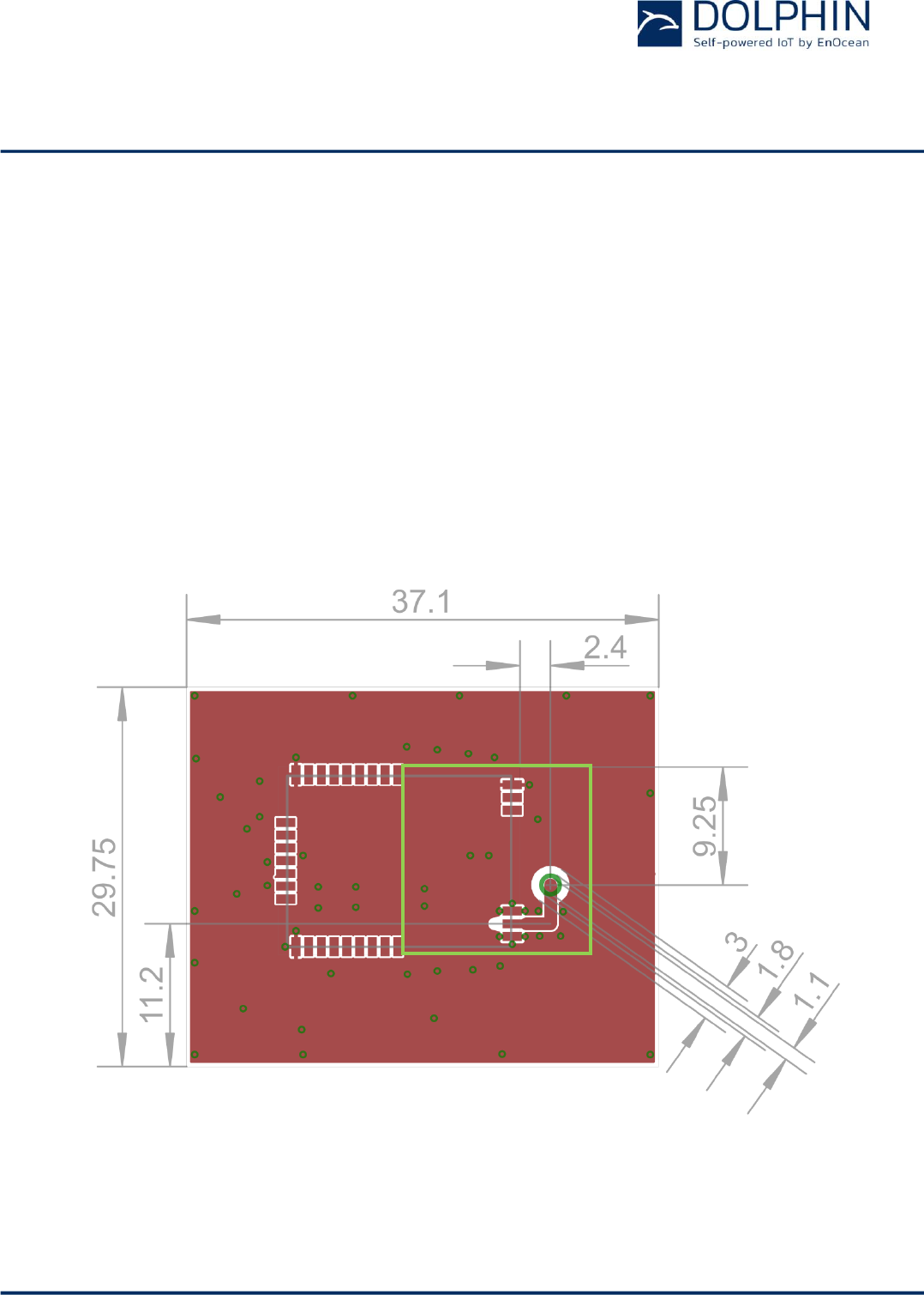
3.2.1 Whip antenna
TCM 515Z has been certified for use with a whip antenna as shown in Figure 3 above which
meets the following parameters:
Antenna length (L): 30 mm wire, connected to via show in Figure 4
Minimum GND plane: 15 mm x 15 mm (green area in Figure 4)
Minimum distance space: 10 mm
The reference layout for this antenna is shown in Figure 4 below. Note that the area within
the green rectangle and the minimum ground plane has to be implemented exactly as
shown.
Figure 4 – Whip antenna reference layout
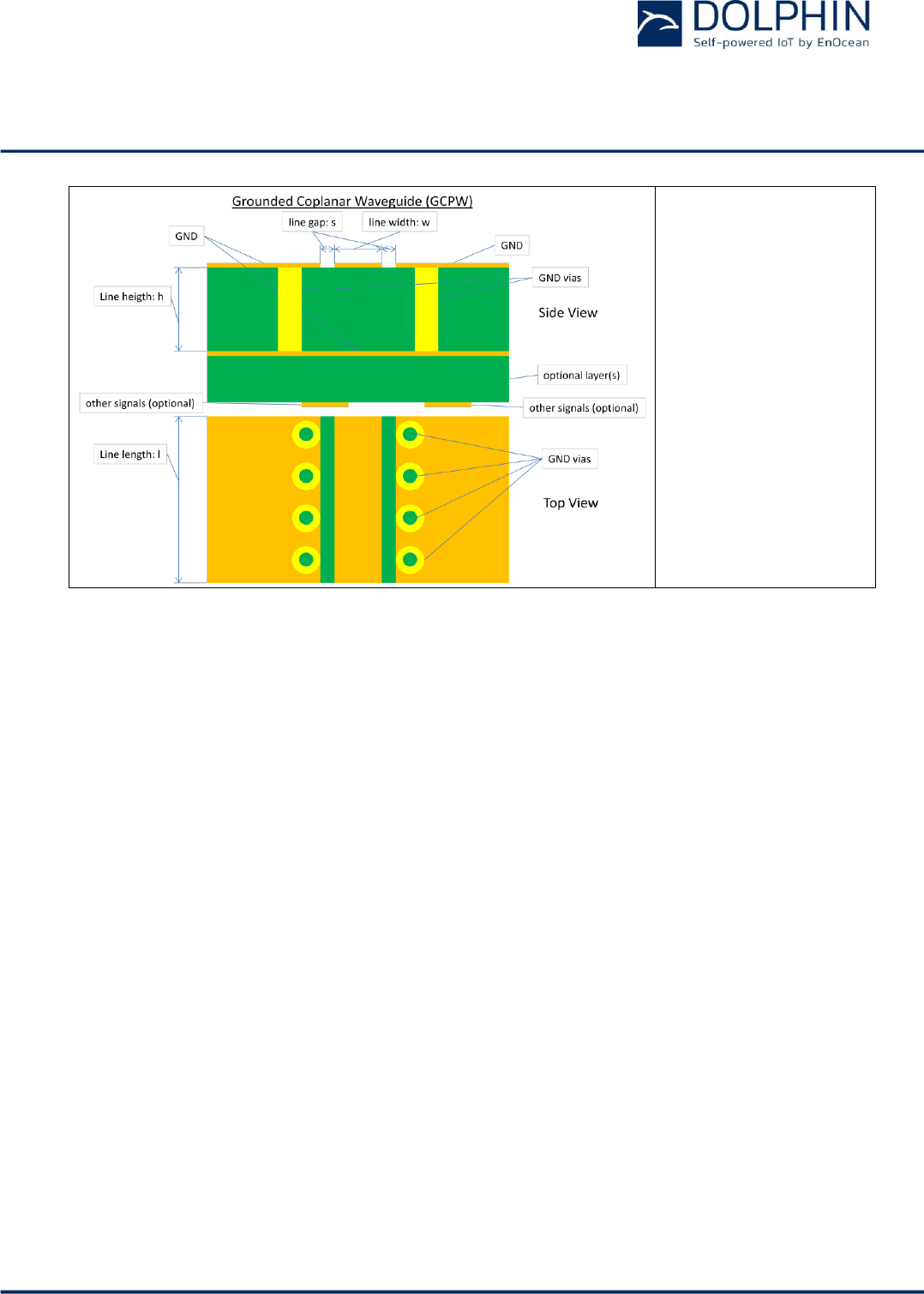
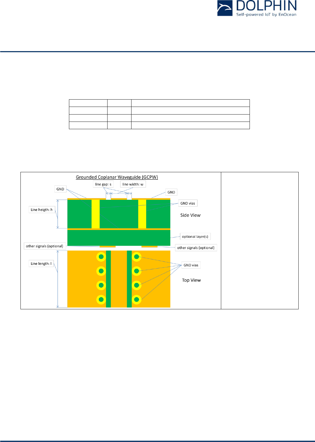
The transmission line between TCM 515Z and the whip antenna has to be implemented as
specified in Figure 5 below.
USER MANUAL
TCM 515Z – 2.4 GHZ IEEE 802.15.4 Transceiver
© 2016 EnOcean | www.enocean.com F-710-017, V1.0 TCM 515Z User Manual | v1.5 | June 2017 | Page 14/45
w=1.00mm
s=0.15mm
h=0.90…2.00mm (See
Note 1)
Typical line impedance
on FR4=44…56Ω
Return loss>=24dB
Figure 5 – Transmission line specification
Note (1): Coplanar waveguide modes are dominant in this configuration. Thus thickness of
substrate can be changed with the given limits.
USER MANUAL
TCM 515Z – 2.4 GHZ IEEE 802.15.4 Transceiver
© 2016 EnOcean | www.enocean.com F-710-017, V1.0 TCM 515Z User Manual | v1.5 | June 2017 | Page 15/45
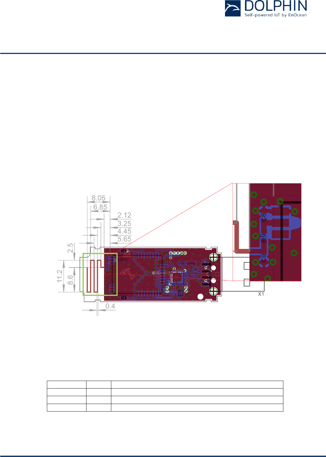
3.2.2 Meandered PCB antenna
TCM 515Z has been certified for use with a meandered PCB antenna provided that the fol-
lowing layout guidelines are met:
Matching circuit values of the modular approval may not be changed
Shape according to reference layout in Figure 6 below
Minimum GND plane: 40 mm x 18 mm
Connect GND planes using multiple via as shown in Figure 6 below
Minimum distance space: 10 mm
Matching circuit components as specified in Table 5 below
Figure 6 below shows the dimensions of the meandered PCB antenna, the matching circuit
and the area important for modular approval (marked in green).
Figure 6 – Reference layout for meandered PCB antenna
Table 5 below lists the parameters of the matching circuit components. It is mandatory to
use them as specified.
Designator
Value
Notes
C8
1.0pF
Use Murata GRM1555 series or similar
R9
6.8nH
Use Würth WE-KI series, Murata LQW series or similar
C9
---
Not assembled
Table 5 – Parameters of the matching circuit
USER MANUAL
TCM 515Z – 2.4 GHZ IEEE 802.15.4 Transceiver
© 2016 EnOcean | www.enocean.com F-710-017, V1.0 TCM 515Z User Manual | v1.5 | June 2017 | Page 16/45
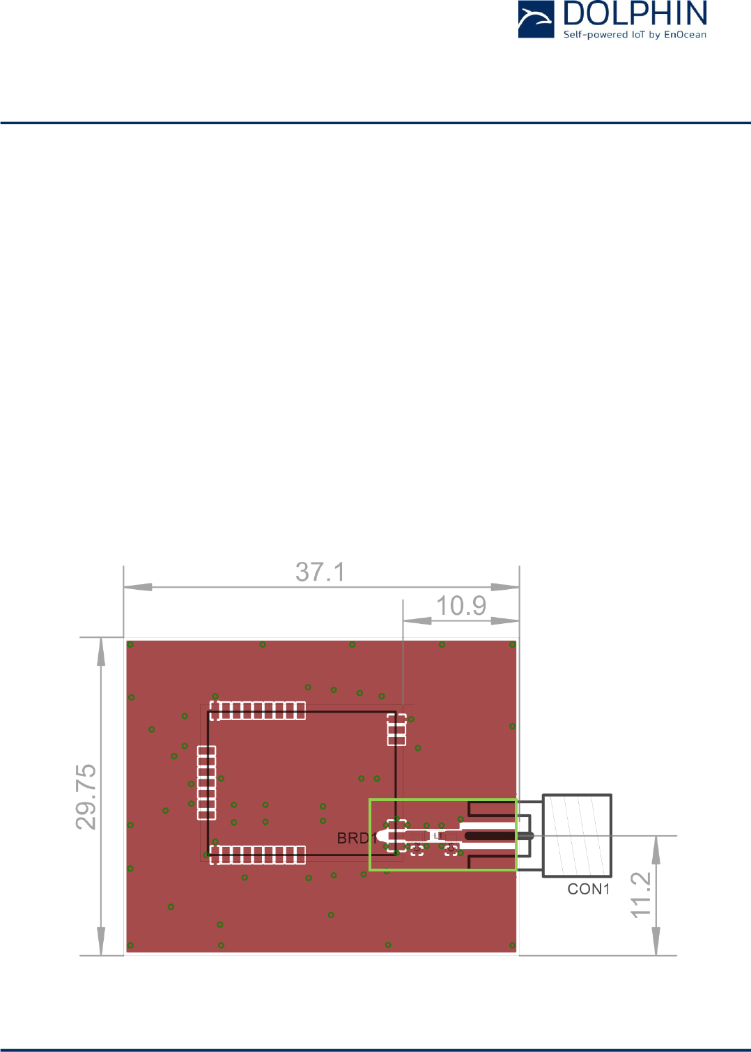
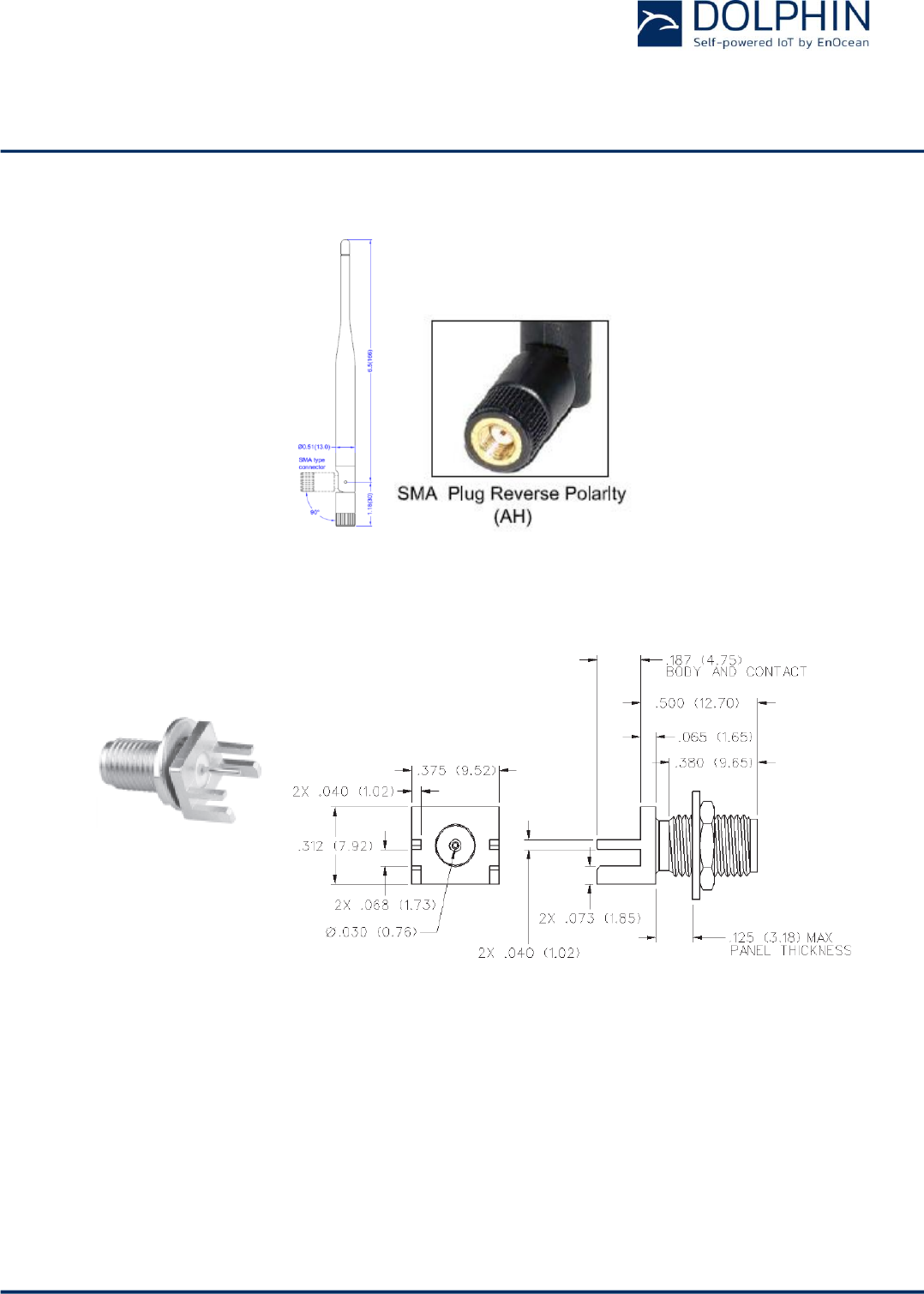
3.2.3 Dipole antenna
The TCM 515Z has been verified for use with the dipole antenna S151AH-2450S from Near-
son or other antennas with similar parameters provided that:
The RF connector is a non-standard connector such as a RP-SMA-Female from John-
son/Cinch Connectivity Solutions (142-4701-801)
The pi low pass filter described in this section is used
In addition, the following layout guidelines have to be met:
The pi low pass filter is part of the modular approval and may not be changed
The bottom GND plane is implemented below the RF transmission line section of the
circuit to form a grounded coplanar waveguide (see Figure 8)
The ground planes have to be connected using multiple via along RF transmission
line as shown in Figure 7 and Figure 8
Table 7 at the end of this section lists dipole antennas that can be used instead of the
S151AH-2450S antenna stated previously as they are the same kind of antennas and have
the same or less gain.
Figure 7 below shows the layout that has been used. The section of the layout located
within the green frame has to remain unchanged for the modular approval.
Figure 7 – Reference layout for dipole antenna
USER MANUAL
TCM 515Z – 2.4 GHZ IEEE 802.15.4 Transceiver
© 2016 EnOcean | www.enocean.com F-710-017, V1.0 TCM 515Z User Manual | v1.5 | June 2017 | Page 17/45
Table 6 below lists the parameters of the components which have to be used for the pi low
pass filter.
Designator
Value
Notes
C1
1.0pF
use Murata GRM1555 series or similar
C2
1.0pF
use Murata GRM1555 series or similar
L1
3.1nH
use Murata LQP15MN series or similar
Table 6 – Values of the pi low pass filter for the dipole antenna
The transmission line between TCM 515Z and the antenna has to be implemented as shown
in Figure 8 below.
w=1.00mm
s=0.15mm
h=0.90…2.00mm (See
Note 1)
Typical line impedance
on FR4=44…56Ω
Return loss>=24dB
Figure 8 – Detailed description of RF transmission line
Note (1): Coplanar waveguide modes are dominant in this configuration. Thus thickness of
substrate can be changed with the given limits.
USER MANUAL
TCM 515Z – 2.4 GHZ IEEE 802.15.4 Transceiver
© 2016 EnOcean | www.enocean.com F-710-017, V1.0 TCM 515Z User Manual | v1.5 | June 2017 | Page 18/45
Figure 9 below shows S151AH-2450S from Nearson.
Figure 9 - S151AH-2450S
Figure 10 below shows the RP-SMA-Female (142-4701-801) from Chinch Connectivity Solu-
tions.
Figure 10 – RP-SMA-Female

USER MANUAL
TCM 515Z – 2.4 GHZ IEEE 802.15.4 Transceiver
© 2016 EnOcean | www.enocean.com F-710-017, V1.0 TCM 515Z User Manual | v1.5 | June 2017 | Page 19/45
3.2.3.1 Dipole antenna options
Table 7 below shows examples of dipole antennas that could be used with TCM 5151Z.
Manufacturer
Manufacturer Part Number
Gain
Antenna Type
Nearson Inc. 1
S151AH-2450S
5dBi
Whip (Dipole), Tilt
Nearson Inc.
S131AH-2450S
5dBi
Whip (Dipole), Tilt
Nearson Inc.
S181AH-2450S
2dBi
Whip (Dipole), Tilt
ATOP Technologies
ANT-WS-AB-RM-05-200
5dBi
Whip (Dipole), Straight
ATOP Technologies
ANT-WS-AB-RM-05-180
5dBi
Whip (Dipole), Straight
Digi International
A24-HASM-525
2.1dBi
Whip (Dipole), Tilt
Digi International
A24-HASM-450
2.1dBi
Whip (Dipole), Tilt
Digi International
DG-ANT-20DP-BG
2dBi
Whip (Dipole), Tilt
Digi International
DC-ANT-24DP
1.8dBi
Whip (Dipole), Tilt
Digi International
DC-ANT-24DT
1.8dBi
Whip (Dipole), Straight
Honeywell
WAN01RSP
2.2dBi
Whip (Dipole), Straight
Honeywell
WAN02RSP
2.2dBi
Whip (Dipole), Tilt
Laird Technologies IAS
S2403BH36RSM
3dBi
Whip (Dipole), Straight
Laird Technologies IAS
EXR2400RSM
3dBi
Whip (Dipole), Tilt
Laird Technologies IAS
MAF94046
1.3dBi
Whip (Dipole), Tilt
Laird Technologies IAS
MAF94028
1.3dBi
Whip (Dipole), Tilt
Laird Technologies IAS
MAF94112
1.5dBi
Whip (Dipole), Tilt
Linx Technologies Inc.
ANT-2.4-CW-HW
3.2dBi
Whip (Dipole), Straight
Linx Technologies Inc.
ANT-2.4-CW-RCT-RP
2.2dBi
Whip (Dipole), Tilt
Linx Technologies Inc.
ANT-2.4-CW-HWR-RPS
3.2dBi
Whip (Dipole), Tilt
Linx Technologies Inc.
ANT-2.4-CW-CT-RPS
2.8dBi
Whip (Dipole), Straight
LSR
001-0010
2dBi
Whip (Dipole), Tilt
LSR
001-0001
2dBi
Whip (Dipole), Tilt
Microchip Technology
RN-SMA4-RP
2.2dBi
Whip (Dipole), Tilt
Proant AB
333
3dBi
Whip (Dipole), Tilt
Proant AB
348
3dBi
Whip (Dipole), Straight
Pulse Electronics
W1037
3.2dBi
Whip (Dipole), Tilt
Pulse Electronics
W1027
3.2dBi
Whip (Dipole), Tilt
Pulse Electronics
W1030
2dBi
Whip (Dipole), Tilt
Pulse Electronics
W5010
1.5dBi
Whip (Dipole), Straight
Pulse Electronics
W5001
1.5dBi
Whip (Dipole), Right Angle
Red Lion Controls
ANT-GW11A153
2.3dBi
Whip (Dipole), Tilt
Siretta Ltd
DELTA6B/X/SMAM/RP/S/11
5dBi
Whip (Dipole), Tilt
Siretta Ltd
DELTA10A/X/SMAM/RP/S/17
3dBi
Whip (Dipole), Straight
Taoglas Limited
GW.11.A153
2.3dBi
Whip (Dipole), Tilt
Taoglas Limited
GW.26.0151
1.8dBi
Whip (Dipole), Straight
Walsin Technology
RFDPA151300SBAB8G1
3dBi
Whip (Dipole), Tilt
Walsin Technology
RFDPA171300SBAB8G1
3dBi
Whip (Dipole), Tilt
Walsin Technology
RFDPA870900SBAB8G1
2dBi
Whip (Dipole), Tilt
Table 7 – Dipole antenna options
1 This antenna was tested for FCC and IC certification
USER MANUAL
TCM 515Z – 2.4 GHZ IEEE 802.15.4 Transceiver
© 2016 EnOcean | www.enocean.com F-710-017, V1.0 TCM 515Z User Manual | v1.5 | June 2017 | Page 20/45
4 Device Integration
TCM 515Z is designed for integration onto a host PCB. Detailed Gerber data of the device
footprint is available from EnOcean upon request.
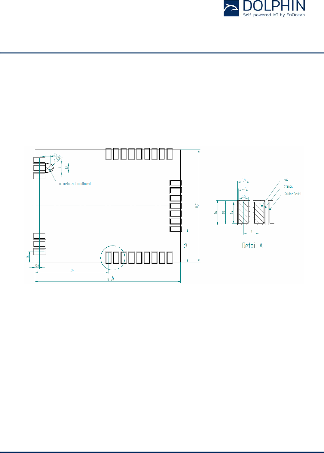
4.1 Recommended PCB Footprint
Figure 11 below shows the recommended PCB footprint for TCM 515Z.
Figure 11 – Recommended PCB footprint
USER MANUAL
TCM 515Z – 2.4 GHZ IEEE 802.15.4 Transceiver
© 2016 EnOcean | www.enocean.com F-710-017, V1.0 TCM 515Z User Manual | v1.5 | June 2017 | Page 21/45
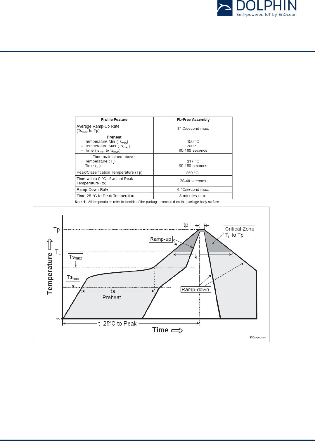
4.2 Soldering information
TCM 515Z has to be soldered according to IPC/JEDEC J-STD-020C standard as outlined in
Figure 12 below.
Figure 12 – Recommended temperature profile

USER MANUAL
TCM 515Z – 2.4 GHZ IEEE 802.15.4 Transceiver
© 2016 EnOcean | www.enocean.com F-710-017, V1.0 TCM 515Z User Manual | v1.5 | June 2017 | Page 22/45
4.3 Device handling instructions
TCM 515Z shall be handled according to Moisture Sensitivity Level MSL 3. TCM 515Z may
be soldered only once, since one time is already consumed at production of the module
itself.
Once the dry pack bag is opened, the desired quantity of units should be removed and the
bag resealed within two hours. If the bag is left open longer than 30 minutes the desiccant
should be replaced with dry desiccant. If devices have exceeded the specified floor life time
of 168 h, they may be baked according IPC/JEDEC J-STD-033B at max. 90 °C for less than
60 hours.
Devices packaged in moisture-proof packaging should be stored in ambient conditions not
exceeding temperatures of 40 °C or humidity levels of 90% r.H.
TCM 515Z modules have to be soldered within 6 months after delivery!
In general we recommend a no clean flux process. If washing is needed, then TCM 515Z
radio modules have a shield cover with small openings at the top of the edges.
It is very important to mount the modules in a top down position during the drying process
as this will allow getting the aggregated washing fluid removed properly from within the
shield cover area.
To prevent damage, modules have to be checked for any remaining fluid after the drying.
USER MANUAL
TCM 515Z – 2.4 GHZ IEEE 802.15.4 Transceiver
© 2016 EnOcean | www.enocean.com F-710-017, V1.0 TCM 515Z User Manual | v1.5 | June 2017 | Page 23/45
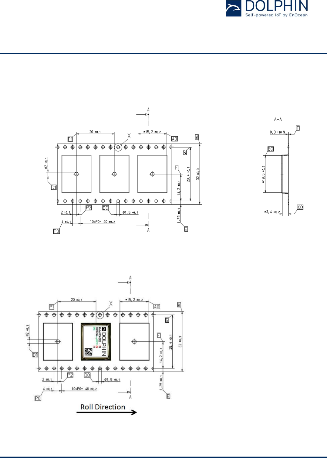
4.4 Tape & Reel specification
TCM 515Z is delivered in Tape & Reel packaging with 250 units per reel. Figure 13 below
illustrates the dimensions.
Figure 13 – Tape & Reel dimensions of TCM 515Z
Figure 14 below shows the positioning of TCM 515Z in the Tape & Reel packaging.
Figure 14 – Position of TCM 515Z in the reel

USER MANUAL
TCM 515Z – 2.4 GHZ IEEE 802.15.4 Transceiver
© 2016 EnOcean | www.enocean.com F-710-017, V1.0 TCM 515Z User Manual | v1.5 | June 2017 | Page 24/45
5 APPLICATION INFORMATION
5.1 Transmission range
The main factors that influence the system transmission range are:
- Type and location of the antennas of receiver and transmitter
- Type of terrain and degree of obstruction of the link path
- Sources of interference affecting the receiver
- “Dead spots” caused by signal reflections from nearby conductive objects.
Since the expected transmission range strongly depends on this system conditions, range
tests should always be performed to determine the reliably achievable range under the
given conditions.
The following figures should be treated as a rough guide only:
- Line-of-sight connections
Typically 15 m range in corridors, up to 50 m in halls
- Plasterboard walls / dry wood
Typically 15 m range, through max. 2 walls
- Ferro concrete walls / ceilings
Maximum 1 wall or ceiling, depending on thickness and material
- Fire-safety walls, elevator shafts, staircases and similar areas should be considered
as shielded
The angle at which the transmitted signal hits the wall is very important. The effective wall
thickness – and with it the signal attenuation – varies according to this angle. Signals
should be transmitted as directly as possible through the wall. Wall niches should be
avoided.
Other factors restricting transmission range include:
- Switch mounting on metal surfaces (up to 30% loss of transmission range)
- Hollow lightweight walls filled with insulating wool on metal foil
- False ceilings with panels of metal or carbon fibre
- Lead glass or glass with metal coating, steel furniture
The distance between the receiver and other transmitting devices such as computers, audio
and video equipment that also emit high-frequency signals should be at least 0.5 m.

USER MANUAL
TCM 515Z – 2.4 GHZ IEEE 802.15.4 Transceiver
© 2016 EnOcean | www.enocean.com F-710-017, V1.0 TCM 515Z User Manual | v1.5 | June 2017 | Page 25/45
6 REGULATORY INFORMATION
TCM 515Z has been certified according to FCC, IC and CE regulations.
Changes or modifications not expressly approved by EnOcean could void the user's authori-
ty to operate the equipment.
6.1 CE (RED) for European Union
According to lows of the member states of the European Union OEM manufacturer or dis-
tributor are responsible for the conformity of the product. In order to support our custom-
ers we have done a summary for download at the product web site (Attestation of Con-
formity).
Note the following requirements for CE certification:
The existing R&TTE directive has been replaced by RED (radio equipment directive) since
13th of June 2016.
OEM manufacturers or distributors which sell this component as a product to his (final) cus-
tomers have to fulfill all requirements of the radio equipment directive (RED).
RED contains at least following requirements for OEM manufacturers or distributors:
Provide product branding (on the product) clearly identifying company name or
brand and product name as well as type, charge or serial number for market surveil-
lance
Include (with the product) documentation containing full postal address of the man-
ufacturer as well as radio frequency band and max. transmitting power
Include (with the product) user manual, safety information and a declaration of con-
formity for the final product in local language
Provide product development and test documentation upon request
OEM has to fulfill all additional requirements according to RED such as market sur-
veillance or 10 years record retention.
For details and national translations, please see:
http://eur-lex.europa.eu/legal-content/EN/TXT/?uri=celex:32014L0053

USER MANUAL
TCM 515Z – 2.4 GHZ IEEE 802.15.4 Transceiver
© 2016 EnOcean | www.enocean.com F-710-017, V1.0 TCM 515Z User Manual | v1.5 | June 2017 | Page 26/45
6.2 FCC (United States) Certificate
<To Be Inserted>

USER MANUAL
TCM 515Z – 2.4 GHZ IEEE 802.15.4 Transceiver
© 2016 EnOcean | www.enocean.com F-710-017, V1.0 TCM 515Z User Manual | v1.5 | June 2017 | Page 27/45
6.2.1 FCC (United States) Regulatory Statement
This device complies with part 15 of the FCC Rules. Operation is subject to the following
two conditions:
(1) this device may not cause harmful interference, and
(2) this device must accept any interference received, including interference that may
cause undesired operation.
6.2.2 FCC (United States) Labeling Requirements
This module is labeled with its own FCC ID number, and, if the FCC ID is not visible when
this module is installed inside another device, then the outside of this device into which the
module is installed must also display a label referring to this enclosed module.
This exterior label can use wording such as the following:
"Contains Transmitter Module FCC ID: SVZ-TCM515Z"
or
"Contains FCC ID: SVZ-TCM515Z"
Any similar wording that expresses the same meaning may be used.
Figure 15: Example Label
6.2.3 FCC (United States) RF Expose
This module must not be used within a separation distance of 20cm or less between the
user and/or bystander and the antenna and/or radiating element.
Calculation of e.i.r.p. (effective isotropic radiated power):
conducted output power: 2.9dBm
maximum gain of antenna: 5.0dBi
maximum e.i.r.p.: 7.9dBm
maximum e.i.r.p. in Watts: 0.00617W
Exception limit for conduted output power
(or e.i.r.p.), when distance >20cm: 1.31 x 10⁻² ƒ0.6834 W (f in MHz)
Frequency: 2500MHz
Limit: 2.75W
Contains FCC ID: SVZ-TCM515Z

USER MANUAL
TCM 515Z – 2.4 GHZ IEEE 802.15.4 Transceiver
© 2016 EnOcean | www.enocean.com F-710-017, V1.0 TCM 515Z User Manual | v1.5 | June 2017 | Page 28/45
6.3 IC (Industry Canada) Certificate
<To Be Inserted >
6.3.1 IC (Industry Canada) Regulatory Statement
This device complies with Industry Canada licence-exempt RSS standard(s).
Operation is subject to the following two conditions:
(1) this device may not cause interference, and
(2) this device must accept any interference, including interference that may cause unde-
sired operation of the device.
Le présent appareil est conforme aux CNR d'Industrie Canada applicables aux appareils
radio exempts de licence.
L'exploitation est autorisée aux deux conditions suivantes :
(1) l'appareil ne doit pas produire de brouillage, et
(2) l'utilisateur de l'appareil doit accepter tout brouillage radioélectrique subi, même si le
brouillage est susceptible d'en compromettre le fonctionnement.”
6.3.2 IC (Industry Canada) RF Expose
This module must not be used within a separation distance of 20cm or less between the
user and/or bystander and the antenna and/or radiating element.
Calculation of e.i.r.p. (effective isotropic radiated power):
conducted output power: 2.9dBm
maximum gain of antenna: 5.0dBi
maximum e.i.r.p.: 7.9dBm
maximum e.i.r.p. in Watts: 0.00617W
Exception limit for conduted output power
(or e.i.r.p.), when distance >20cm: 1.31 x 10⁻² ƒ0.6834 W
Frequency: 2500MHz
Limit: 2.75W

USER MANUAL
TCM 515Z – 2.4 GHZ IEEE 802.15.4 Transceiver
© 2016 EnOcean | www.enocean.com F-710-017, V1.0 TCM 515Z User Manual | v1.5 | June 2017 | Page 29/45
Appendix A IEEE 802.15.4 Frame Structure
A.1 IEEE 802.15.4 High Level Frame Structure
TCM 515Z transmits and receives radio telegrams in the 2.4 GHz band according to IEEE
802.15.4 frame structure. The external host is responsible for the proper decoding of re-
ceived telegrams and proper encoding of telegrams to be transmitted.
The following information about the IEEE 802.15.4 standard and its implementation in PTM
215ZE and PTM 515Z is given for reference only. Please refer to the applicable documents
for detailed information.
Note that the data format is little endian. This means that for multi-byte structures (such as
2 byte, 4 byte or 8 byte fields) the least significant byte (LSB) is transmitted first.
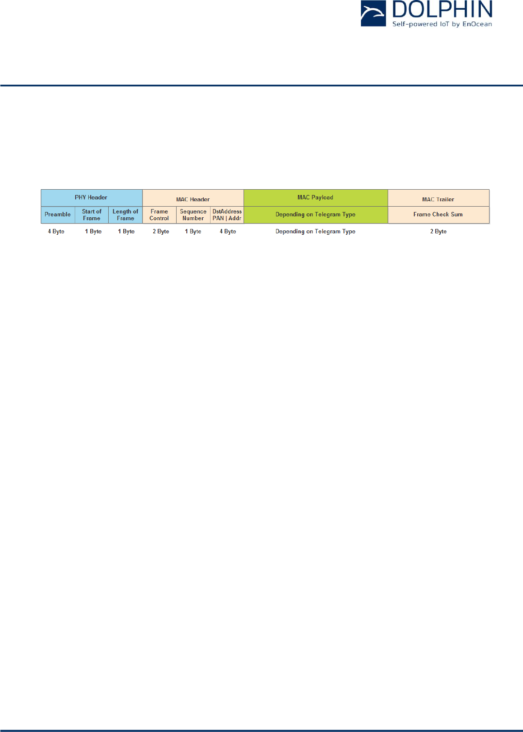
The IEEE 802.15.4 frame structure consists of the following four main parts:
PHY Header
The PHY header indicates to the receiver the start of a transmission and provides in-
formation about the length of the transmission.
It contains the following fields:
o Preamble
Pre-defined sequence (4 byte, value 0x00000000) used to adjust the receiver
to the transmission of the sender
o Start of frame
Pre-defined symbol (1 byte, value 0xA7) identifying the start of the actual
data frame
o Length of Frame
1 byte indicating the combined length of all following fields
MAC Header
The MAC header provides detailed information about the frame.
It contains the following fields:
o Frame control field
2 bytes to identify frame type, protocol version, addressing and security
mode
o Sequence number
1 byte sequential number to identify the order of transmitted frames
o Address
PAN ID and address of source (if present) and destination of the telegram
EnOcean PTM 535Z and PTM 215ZE do not use source address and source
PAN ID (the EnOcean ID is part of the payload).
MAC Payload
The MAC Payload field contains telegram control, device ID, telegram data and tele-
gram security (if present) fields.
The MAC Payload field structure depends on telegram type (data or commissioning)
and security mode (secure or standard transmission).
USER MANUAL
TCM 515Z – 2.4 GHZ IEEE 802.15.4 Transceiver
© 2016 EnOcean | www.enocean.com F-710-017, V1.0 TCM 515Z User Manual | v1.5 | June 2017 | Page 30/45
MAC Trailer
The MAC Trailer contains the Frame Check Sum (FCS) field used to verify the integ-
rity of the telegram data.
Figure 16 below summarizes the IEEE 802.15.4 frame structure.
Figure 16: IEEE 802.15.4 frame structure
The content of these fields is described in more detail below.
A.2 PHY Header
The IEEE 802.15.4 PHY header consists of the following fields:
Preamble
Start of Frame
Length of Frame fields
The content of the Preamble and Start of Frame fields is fixed for all telegram types sup-
ported by EnOcean devices as follows:
Preamble = 0x00000000
Start of Frame = 0xA7
A.2.1 Length of Frame values used by PTM 215ZE and PTM 535Z
Below are reference values for the Length of Frame field for different type of telegrams
used by PTM 215ZE and PTM 535Z:
Secure commissioning telegram (Default for PTM 215ZE and PTM 535Z)
Length of Frame = 42 bytes (0x2A)
Secure data telegram (Default for PTM 215ZE and PTM 535Z)
Length of Frame = 24 bytes (0x18)
Standard commissioning telegram (Optional feature for PTM 535Z only)
Length of Frame = 17 bytes (0x11)
PTM switch: Standard data telegram (Optional feature for PTM 535Z only)
Length of Frame = 15 bytes (0x0F)

USER MANUAL
TCM 515Z – 2.4 GHZ IEEE 802.15.4 Transceiver
© 2016 EnOcean | www.enocean.com F-710-017, V1.0 TCM 515Z User Manual | v1.5 | June 2017 | Page 31/45
A.3 MAC Header
The IEEE 802.15.4 MAC Header contains the following fields:
Frame Control Field (2 byte)
The Frame Control Field is set to 0x0801 in PTM 215ZE and PTM 535Z telegrams in
order to identify them as data telegrams with short addresses based on version IEEE
802.15.4-2003
Sequence Number (1 byte)
The Sequence Number is an incremental number used to identify the order of tele-
grams
Address Field (4 byte in EnOcean implementation)
EnOcean devices use short Destination Address (16 Bit) together with the Destina-
tion PAN ID (16 Bit). Both are set to 0xFFFF to identify the telegrams as broadcast.
Source address and Source PAN ID are not used by PTM 215ZE and PTM 535Z.
A.4 MAC Payload
The IEEE 802.15.4 MAC Payload depends on the telegram type. Appendix B describes the
MAC Payload structure used by EnOcean PTM 215ZE and PTM 535Z products.
A.5 MAC Trailer
The MAC Trailer only contains the Frame Check Sum (FCS) field.
Its length is 2 byte and it is calculated as Cyclic Redundancy Check (CRC16) over the entire
MAC payload including the Length field of the PHY Header using the following polynomial:
x16 + x12 + x5 + 1
TCM 515Z will automatically calculate and append the frame check sum to radio telegrams
it is transmitting.
For received radio telegrams, TCM 515Z will calculate the frame check sum and verify data
integrity based on that. If the checksum does not match, the received radio telegram will
be discarded. Otherwise the received radio telegram will be forwarded to the external host
via the ESP3 interface.

USER MANUAL
TCM 515Z – 2.4 GHZ IEEE 802.15.4 Transceiver
© 2016 EnOcean | www.enocean.com F-710-017, V1.0 TCM 515Z User Manual | v1.5 | June 2017 | Page 32/45
Appendix B MAC Payload Structure
The MAC Payload depends on the telegram type. This appendix gives examples of MAC pay-
load structures used by EnOcean PTM 215ZE and PTM 535Z devices.
The following telegram types are used by these devices:
Data telegram
Commissioning telegram
The following security modes are supported by these devices:
Secure (authenticated) communication (using AES128 authentication)
Default mode on PTM 215ZE and PTM 535Z
Standard communication (without AES128 authentication)
Optional mode for PTM 535Z, not available for PTM 215ZE
Standard communication (without AES128 security processing) is supported as an optional
feature for PTM 535Z in case shorter payloads are desired for certain applications without
requirements for telegram authentication. This mode is not available for PTM 215ZE.
USER MANUAL
TCM 515Z – 2.4 GHZ IEEE 802.15.4 Transceiver
© 2016 EnOcean | www.enocean.com F-710-017, V1.0 TCM 515Z User Manual | v1.5 | June 2017 | Page 33/45
B.1 Secure data telegram format (with authentication)
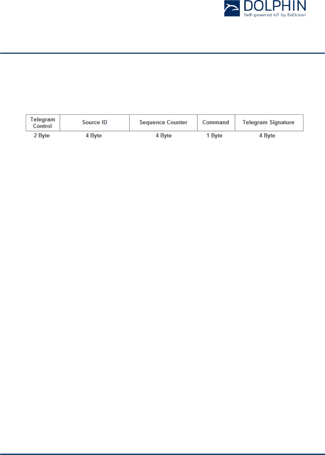
Figure 17 below shows the MAC Payload structure of a secure data telegram with authenti-
cation used by PTM 215ZE or PTM 535Z.
Figure 17: MAC Payload structure for authenticated data telegrams
The following fields are used:
Telegram Control (2 bytes)
The default security mode of PTM 215ZE and PTM 535Z uses a 4 byte payload signa-
ture based on a device-unique key and a 4 byte Sequence Counter.
The Telegram Control field is set to 0x308C for this mode.
Source ID (4 bytes)
The Source ID field contains a 4 byte ID uniquely identifying each PTM 215ZE or
PTM 535Z device
Sequence Counter (4 bytes)
The Sequence Counter field contains an always incrementing counter.
Security processing is based on the combination of the Command and Sequence
Counter in order to prevent replay attacks (sending the same telegram again)
Command (1 byte)
The Command field is a one byte field which identifies the state of the different in-
puts of PTM 215ZE or PTM 535Z. For the encoding please see the applicable data
manual.
Telegram Signature (4 byte)
The Telegram Signature field is used to validate the telegram authenticity. The tele-
gram signature is calculated based on the telegram payload using AES128 (CBC
mode).
In this mode, telegrams contain both a 4 byte sequence counter and a 4 byte signature
which is calculated based on the telegrams payload (including the sequence counter)
and the private key. The implementation is specified in RFC3610 and compatible with
ZigBee systems.
EnOcean can provide upon request additional information on how to implement tele-
gram validation for PTM 215ZE or PTM 535Z data telegrams.

USER MANUAL
TCM 515Z – 2.4 GHZ IEEE 802.15.4 Transceiver
© 2016 EnOcean | www.enocean.com F-710-017, V1.0 TCM 515Z User Manual | v1.5 | June 2017 | Page 34/45
B.2 Secure commissioning telegram format (with authentication)
Figure 18 below shows the MAC payload structure of a secure commissioning telegram used
by PTM 215ZE and PTM 535Z.
Figure 18: MAC Payload structure for secure commissioning telegrams
The following fields are used for secure commissioning telegrams:
Telegram Control (1 byte)
The Telegram Control field is set to 0x0C to identify a standard telegram (secure
communication will be established based on the commissioning telegram)
Source ID (4 bytes)
The Source ID field contains a 4 byte ID uniquely identifying each PTM 215ZE or
PTM 535ZE device
Commissioning Command (1 byte)
The Command field is set to 0xE0 by PTM 215ZE and PTM 535Z
Device Type (1 byte)
The Device Type field is set to 0x02 by PTM 215ZE and PTM 535Z
Device Options (2 bytes)
The Device Options field is set to 0xF281 by PTM 215ZE and PTM 535Z when operat-
ing in AES128 secure mode with authentication.
The Device Options field is set to 0xF381 by PTM 535Z when operating in AES128
secure mode with authentication and additional payload encryption (optional fea-
ture).
Device-unique Security Key (16 bytes)
PTM 215ZE and PTM 535Z implement a random, device-specific security key which
is generated as part of the production flow. During commissioning, this key is
transmitted in encrypted format. Contact EnOcean for details.
Security Key Validation (4 bytes)
In order to ensure correct reception, an additional 4 byte validation value is pro-
vided. Contact EnOcean for details.
Sequence Counter (4 bytes)
The Sequence Counter is an always incrementing counter which is used as part of
the security processing to avoid replay attacks (sending the same telegram again).
Receiving devices shall only accept data telegrams with sequence counter values
higher than that of the last received telegram; therefore the current value needs to
be communicated during commissioning.
USER MANUAL
TCM 515Z – 2.4 GHZ IEEE 802.15.4 Transceiver
© 2016 EnOcean | www.enocean.com F-710-017, V1.0 TCM 515Z User Manual | v1.5 | June 2017 | Page 35/45
B.3 Standard data telegram format (without authentication)
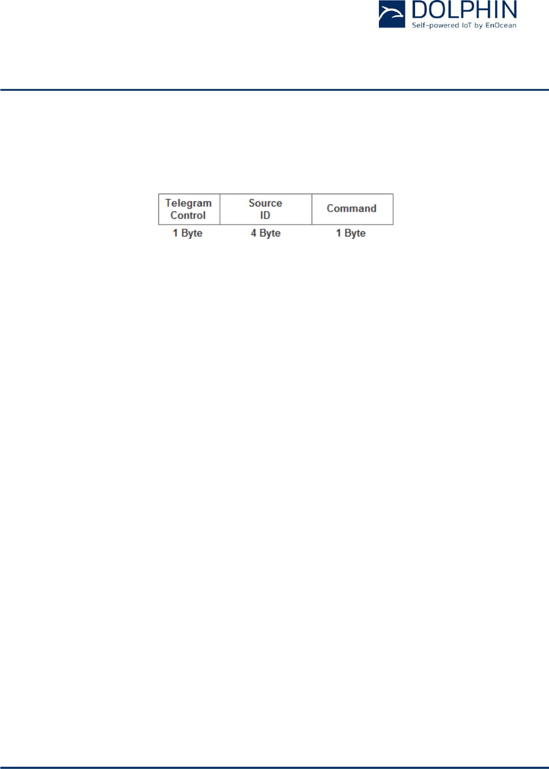
Figure 19 below shows the MAC Payload structure of a standard data telegram. This tele-
gram type is an optional feature of PTM 535Z.
Figure 19: MAC Payload structure for standard data telegrams
The following fields are used for Standard Data Telegrams:
Telegram Control (1 byte)
The Telegram Control field is set to 0x0C by PTM 535Z to identify a standard data
telegram
Source ID (4 bytes)
The Source ID field contains a 4 byte ID uniquely identifying each PTM 535Z device
Command (1 byte)
The Command field is a one byte field which identifies the state of the PTM 215ZE
button contacts or PTM 535Z input signals. For the encoding please refer to the ap-
plicable datasheet.
USER MANUAL
TCM 515Z – 2.4 GHZ IEEE 802.15.4 Transceiver
© 2016 EnOcean | www.enocean.com F-710-017, V1.0 TCM 515Z User Manual | v1.5 | June 2017 | Page 36/45
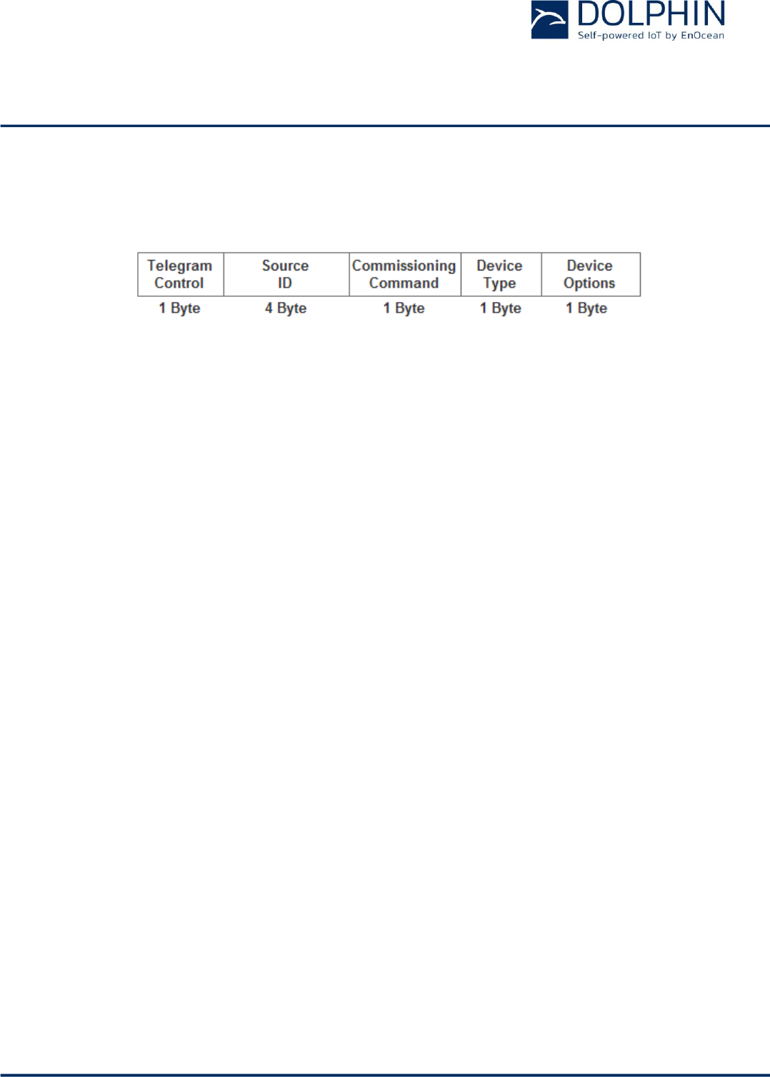
B.4 Standard commissioning telegram (without authentication)
Figure 20 below shows the MAC payload structure of a standard commissioning telegram
used by PTM 535Z.
Figure 20: MAC Payload structure for standard commissioning telegrams
The following fields are used for standard commissioning telegrams:
Telegram Control (1 byte)
The Telegram Control field is set to 0x0C to identify a standard telegram (secure
communication will be established based on the commissioning telegram)
Source ID (4 bytes)
The Source ID field contains a 4 byte ID uniquely identifying each PTM 535Z device
Commissioning Command (1 byte)
The Commissioning Command field is set to 0xE0 by PTM 535Z
Device Type (1 byte)
The Device Type field is set to 0x02 by PTM 535Z
Device Options (1 byte)
The Device Options field is set to 0x01 by PTM 535Z

USER MANUAL
TCM 515Z – 2.4 GHZ IEEE 802.15.4 Transceiver
© 2016 EnOcean | www.enocean.com F-710-017, V1.0 TCM 515Z User Manual | v1.5 | June 2017 | Page 37/45
Appendix C ESP3 Interface Format
C.1 Packet Type 0x10: IEEE 802.15.4 Raw Packet
In receive mode, TCM 515Z forwards the content of received IEEE 802.15.4 radio telegrams
(which pass frame check sum validation) unmodified to the external host via the ESP3 in-
terface.
The forwarded frame starts with the Length field of the IEEE 802.15.4 PHY Header, contin-
ues with the MAC Header and ends with the last Byte of the MAC Payload. The frame check
sum (MAC Trailer) will not be forwarded to the host.
In transmit mode, TCM 515Z receives from the external host the precomputed message
payload starting with the Length field of the IEEE 802.15.4 PHY Header, continuing with the
MAC Header and ending with the last Byte of the MAC Payload.
TCM 515Z then calculates the frame check sum (MAC Trailer) based on the received pay-
load and appends it to the message. The full frame (including the Preamble and Start of
Frame fields) will then be transmitted as IEEE 802.15.4 radio telegram (TX mode).
C.1.1 ESP3 packet structure for IEEE 802.15.4 Raw Packets
The MAC frame is embedded as 802.15.4 payload into the ESP3 packet as shown in Figure
21 below.
Figure 21: ESP3 packet structure for IEEE 802.15.4 Raw Packets
CRC8D
Header
CRC8H
Optional Data
Sync Byte
802.15.4 Payload
ESP3
Packet
Data Payload
USER MANUAL
TCM 515Z – 2.4 GHZ IEEE 802.15.4 Transceiver
© 2016 EnOcean | www.enocean.com F-710-017, V1.0 TCM 515Z User Manual | v1.5 | June 2017 | Page 38/45
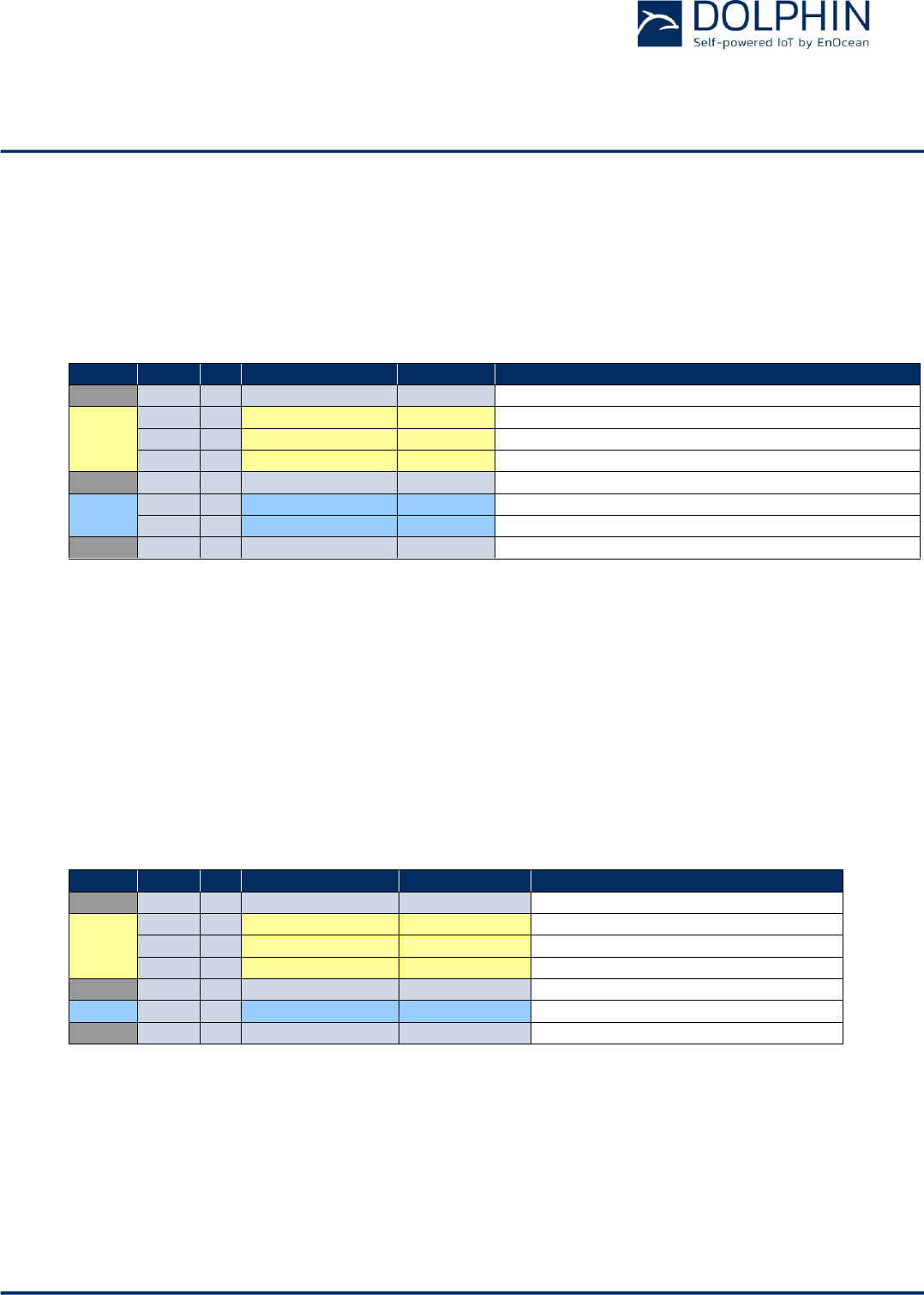
The detailed structure of the IEEE 802.15.4 Raw Packets is shown in Table 8 below.
IEEE 802.15.4 Raw Packets are identified by Packet Type 0x10.
Group
Offset
Size
Field
Value hex
Description
-
0
1
Sync. byte
0x55
Header
1
2
Data Length
0xnnnn
Variable length x of raw packet payload
3
1
Optional Length
0x01
1 field fixed
4
1
Packet Type
0x10
Packet Type 0x10: 802.15.4 Raw Packet
-
5
1
CRC8H
0xnn
Data
6
x
Raw data
...
...
802.15.4 Raw Packet payload
Optional
Data
6+x
1
RSSI
0xnn
Send case: FF
Receive case: best RSSI value of all received
sub telegrams (value decimal without minus)
-
7+x
1
CRC8D
0xnn
CRC8 Data byte;
Calculated checksum for whole byte groups:
DATA and OPTIONAL_DATA
Table 8 – Packet structure for IEEE 802.15.4 Raw Packets
C.1.2 RESPONSE for IEEE 802.15.4 Raw Packets
When receiving a telegram, no RESPONSE has to be sent from the external host to the
gateway to acknowledge reception of the telegram via ESP3 interface.
When transmitting a telegram, the gateway will send a RESPOND message to the external
host via ESP3 interface to indicate the acceptance of the telegram for transmission. The
following return codes are applicable for such a RESPONSE message:
00 RET_OK
02 RET_NOT_SUPPORTED
03 RET_WRONG_PARAM
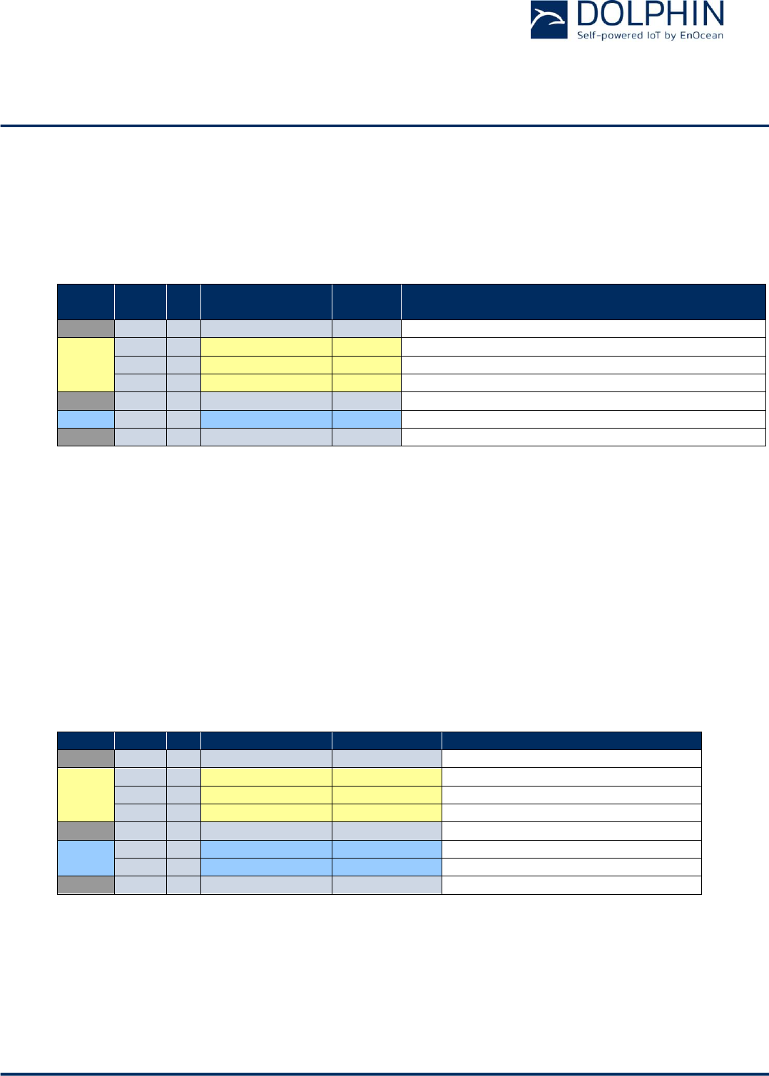
The structure of the gateway RESPONSE message to the request for transmission of an
IEEE 802.15.4 Raw Packet is shown in Table 9 below. TCM 515Z will transmit a dedicated
message to a connected host if transmission of an accepted telegram subsequently fails.
Group
Offset
Size
Field
Value hex
Description
-
0
1
Sync. byte
0x55
Header
1
2
Data Length
0x0004
1 byte
3
1
Optional Length
0x00
0 byte
4
1
Packet Type
0x02
Packet Type 0x02: RESPONSE
-
5
1
CRC8H
0xnn
Data
6
1
Return Code
0xnn
00 / 02 / 03
-
7
1
CRC8D
0xnn
Table 9 - RESPONSE frame structure to IEEE 802.15.4 Raw Packet transmission
USER MANUAL
TCM 515Z – 2.4 GHZ IEEE 802.15.4 Transceiver
© 2016 EnOcean | www.enocean.com F-710-017, V1.0 TCM 515Z User Manual | v1.5 | June 2017 | Page 39/45
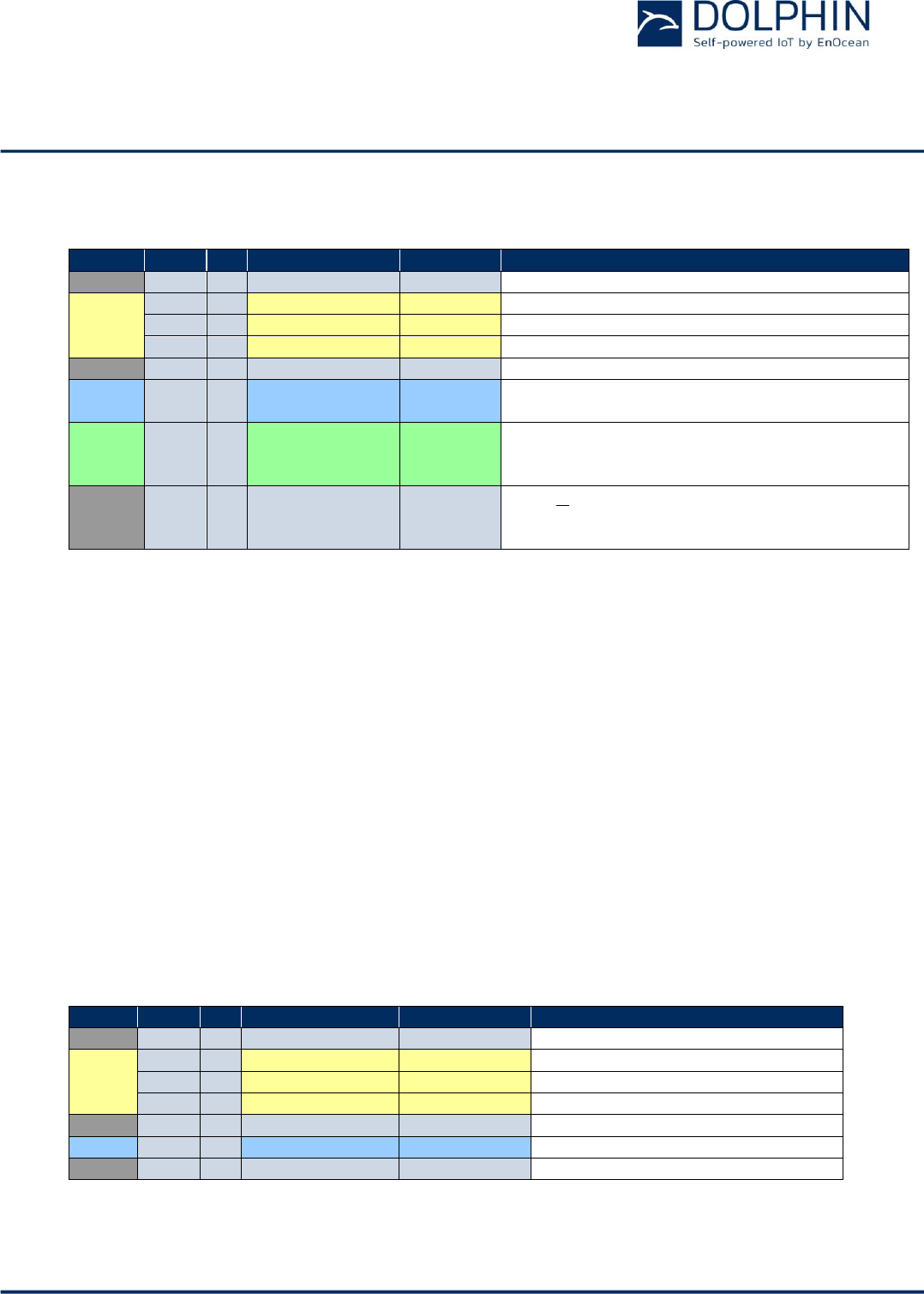
C.1.3 Failure Indication for IEEE 802.15.4 Raw Packet
TCM 515Z will accept and immediately acknowledge via ESP3 correctly formatted telegrams
for radio transmission as described above.
Should transmission subsequently fail due to channel non-availability then this will be sub-
sequently indicated to the host using an ESP3 Event (Packet Type 0x04) with Event Code
07: CO_TRANSMIT_FAILED.
The structure of ESP3 Event messages is shown in Figure 22 below.
Figure 22: ESP3 packet structure for Events
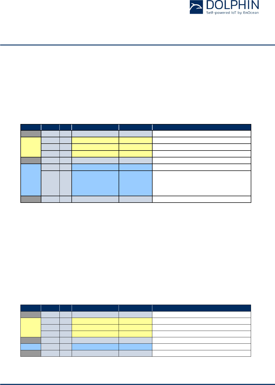
The structure of the CO_TRANSMIT_FAILED Event is shown in Table 10 below.
Group
Offset
Size
Field
Value hex
Description
-
0
1
Sync. Byte
0x55
Header
1
2
Data Length
0x0002
2 bytes
3
1
Optional Length
0x00
0 byte
4
1
Packet Type
0x04
EVENT = 4
-
5
1
CRC8H
0xnn
Data
6
1
Event Code
0x07
CO_TRANSMIT_FAILED = 7
7
1
Event Cause
0xnn
00 = CSMA failed, channel was never free
01 = No Acknowledge received, telegram was
transmitted, but no ack received.
02…255 = reserved
-
8
1
CRC8D
0xnn
Table 10 – Structure of Event Code 07: CO_TRANSMIT_FAILED
CRC8D
Header
CRC8H
Sync Byte
Optional Data = 0
Data
Event Code
Event Data
(optional)
USER MANUAL
TCM 515Z – 2.4 GHZ IEEE 802.15.4 Transceiver
© 2016 EnOcean | www.enocean.com F-710-017, V1.0 TCM 515Z User Manual | v1.5 | June 2017 | Page 40/45
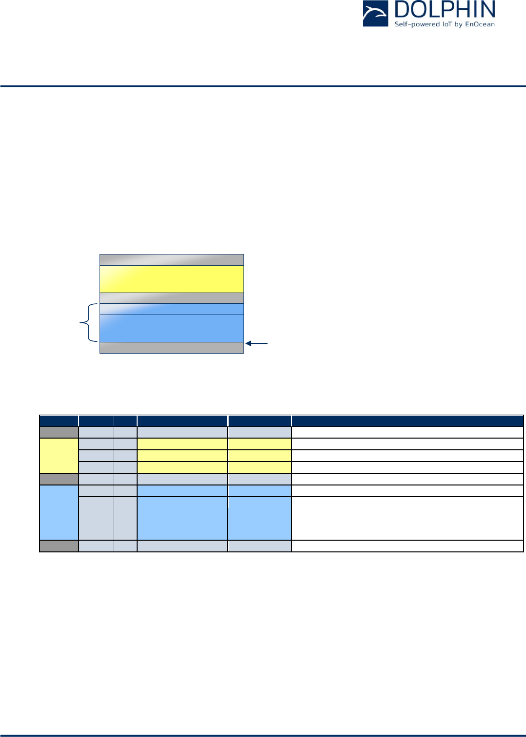
C.2 Packet Type 0x11: IEEE 802.15.4 COMMAND
The packet type IEEE 802.15.4 COMMAND is used to set and read parameters of TCM 515Z.
C.2.1 Packet structure for IEEE 802.15.4 COMMAND
The packet structure for IEEE 802.15.4 COMMAND is shown in Figure 23 below.
Figure 23 - Packet structure for IEEE 802.15.4 COMMAND
The structure of supported commands and expected responses are described in detail in the
following chapters.
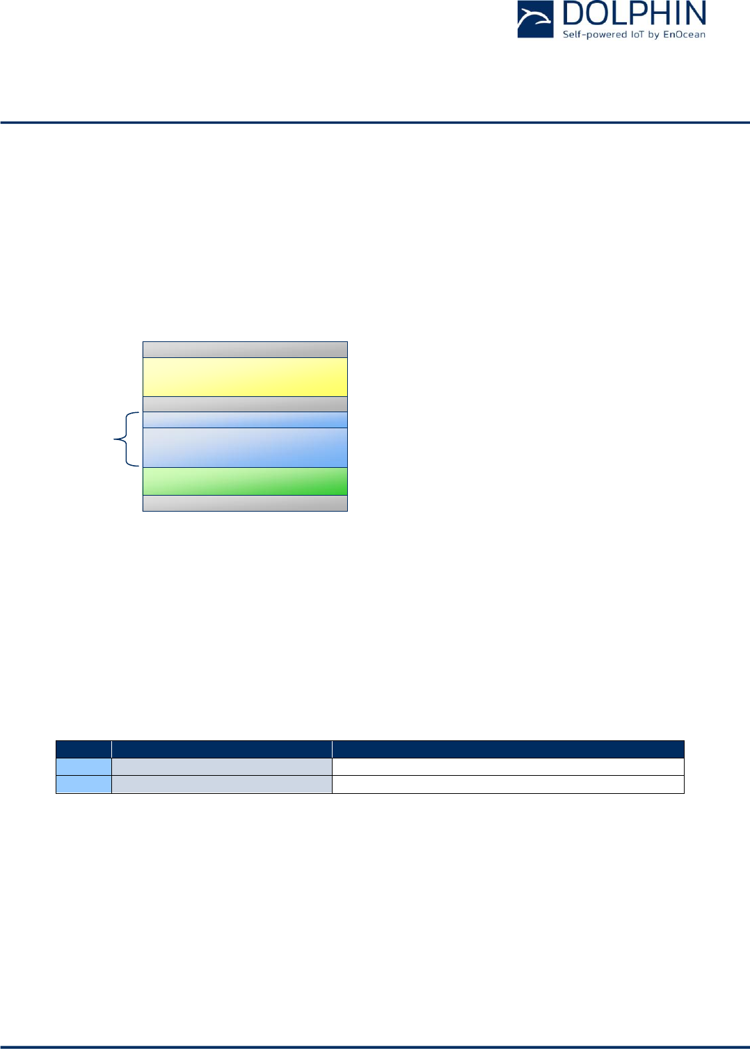
C.2.2 List of supported commands
Table 11 below lists the currently supported commands.
Code
Command Name
Description
01
SET_CHANNEL
Sets the radio channel used by the gateway
02
GET_CHANNEL
Reads the radio channel used by the gateway
Table 11 - List of supported commands
CRC8D
Header
CRC8H
Optional Data
Sync Byte
Data
Command Code
Command Data
USER MANUAL
TCM 515Z – 2.4 GHZ IEEE 802.15.4 Transceiver
© 2016 EnOcean | www.enocean.com F-710-017, V1.0 TCM 515Z User Manual | v1.5 | June 2017 | Page 41/45
C.2.3 SET_CHANNEL Command
The SET_CHANNEL command sets the radio channel used by TCM 515Z. Please refer to
chapter 2.3 for details about the supported radio channels.
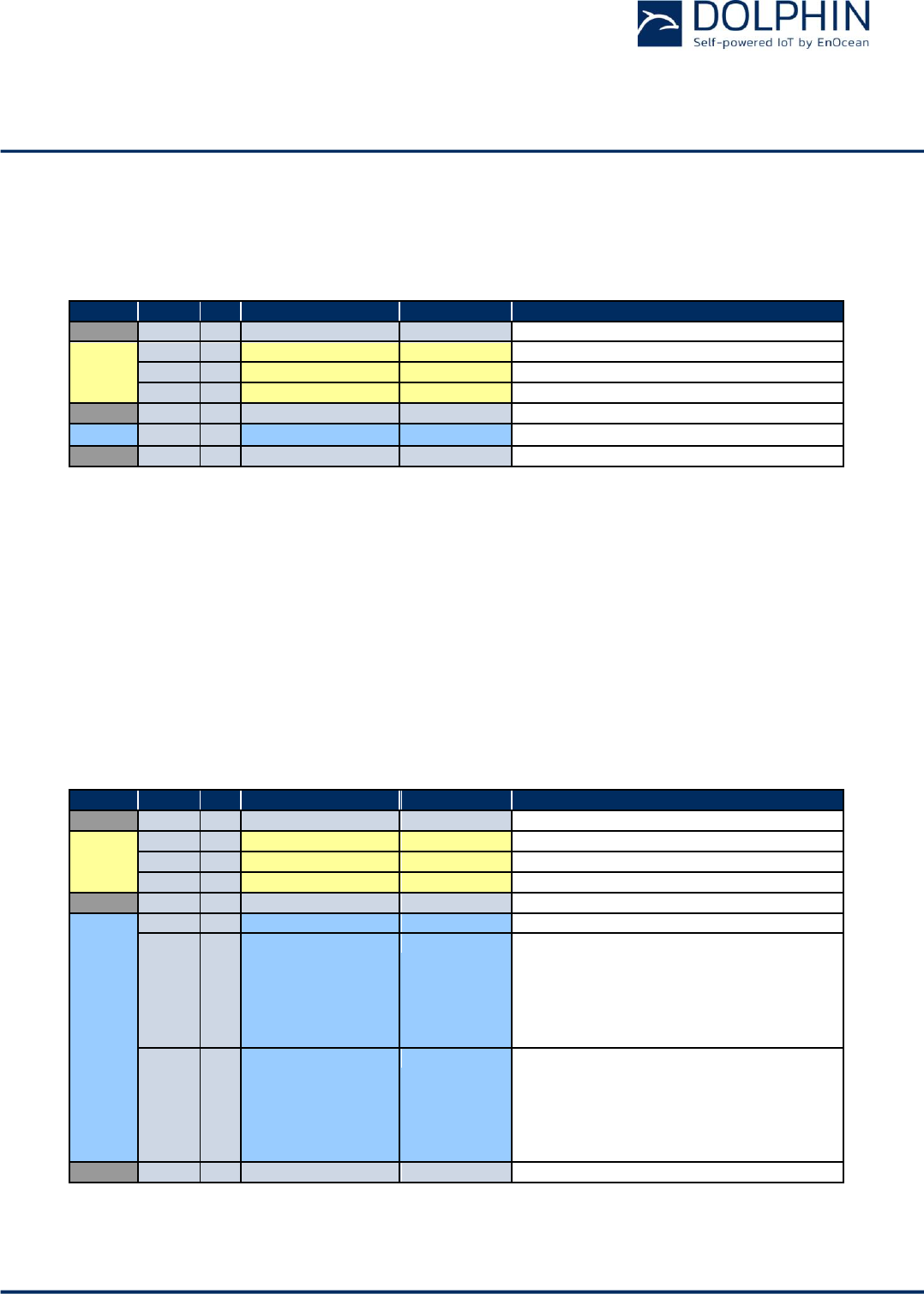
The command structure of the SET_CHANNEL command is shown in Table 12 below.
Group
Offset
Size
Field
Value hex
Description
-
0
1
Sync. byte
0x55
Header
1
2
Data Length
0x0002
2 bytes
3
1
Optional Length
0x00
0 byte
4
1
Packet Type
0x11
Packet Type 0x11: IEEE 802.15.4 COMMAND
-
5
1
CRC8H
0xnn
Data
6
1
COMMAND Code
0x01
COMMAND 0x01: SET_CHANNEL
7
1
Channel
11-26
IEEE 802.15.4 radio channel
-
8
1
CRC8D
0xnn
Table 12 - Command Structure for the SET_CHANNEL command
C.2.4 RESPONSE for SET_CHANNEL Command
The expected RESPONSE code for a SET_CHANNEL command is:
00: RET_OK
The frame structure for a RESPONSE to the SET_CHANNEL command is shown in Table 13
below.
Group
Offset
Size
Field
Value hex
Description
-
0
1
Sync. byte
0x55
Header
1
2
Data Length
0x0001
1 byte
3
1
Optional Length
0x00
0 byte
4
1
Packet Type
0x02
Packet Type 0x02: RESPONSE
-
5
1
CRC8H
0xnn
Data
6
1
Return Code
0xnn
00
-
7
1
CRC8D
0xnn
Table 13 - RESPONSE Frame Structure for SET_CHANNEL command
USER MANUAL
TCM 515Z – 2.4 GHZ IEEE 802.15.4 Transceiver
© 2016 EnOcean | www.enocean.com F-710-017, V1.0 TCM 515Z User Manual | v1.5 | June 2017 | Page 42/45
C.2.5 GET_CHANNEL Command
The GET_CHANNEL command requests information about the radio channel currently used
by TCM 515Z. The command structure of the GET_CHANNEL command is shown in Table 14
below.
Group
Offset
Size
Field
Value
hex
Description
-
0
1
Sync. byte
0x55
Header
1
2
Data Length
0x0001
1 byte
3
1
Optional Length
0x00
0 byte
4
1
Packet Type
0x11
Packet Type 0x11: IEEE 802.15.4 COMMAND
-
5
1
CRC8H
0xnn
Data
6
1
COMMAND Code
0x02
COMMAND 0x02: GET_CHANNEL
-
7
1
CRC8D
0xnn
Table 14 - Command structure of the GET_CHANNEL command
C.2.6 RESPONSE for GET_CHANNEL Command
The expected RESPONSE code for a GET_CHANNEL command issued to TCM 515Z is:
00: RET_OK
The currently used radio channel is then encoded in the subsequent byte. The frame struc-
ture for a RESPONSE to the GET_CHANNEL command is shown in Table 15 below.
Group
Offset
Size
Field
Value hex
Description
-
0
1
Sync. byte
0x55
Header
1
2
Data Length
0x0002
2 bytes
3
1
Optional Length
0x00
0 byte
4
1
Packet Type
0x02
COMMAND 0x02: GET_CHANNEL
-
5
1
CRC8H
0xnn
Data
6
1
Return Code
0
OK
7
1
Channel
11..26
Used Channel
-
8
1
CRC8D
0xnn
Table 15 - RESPONSE frame structure for GET_CHANNEL command
USER MANUAL
TCM 515Z – 2.4 GHZ IEEE 802.15.4 Transceiver
© 2016 EnOcean | www.enocean.com F-710-017, V1.0 TCM 515Z User Manual | v1.5 | June 2017 | Page 43/45
C.3 Packet Type Common Command
C.3.1 Command Code 0x24: CO_SET_BAUDRATE
The command CO_SET_BAUDRATE modifies the baud rate of the ESP3 interface. The
standard baud rate defined by the ESP3 interface is 57600 Baud. TCM 515Z supports faster
baud rates as listed in Table 16 below.
Group
Offset
Size
Field
Value hex
Description
-
0
1
Sync. byte
0x55
Header
1
2
Data Length
0x0002
2 bytes
3
1
Optional Length
0x00
0 byte
4
1
Packet Type
0x05
COMMON_COMMAND = 0x05
-
5
1
CRC8H
0xnn
Data
6
1
COMMAND Code
0x24
CO_SET_BAUDRATE = 0x24
7
1
BAUDRATE
0xnn
0x00 = 57600 BAUD
0x01 = 115200 BAUD
0x02 = 230400 BAUD
0x03 = 460800 BAUD
-
8
1
CRC8D
0xnn
Table 16 - Command structure of the CO_SET_BAUDRATE command
Caution: Before using the CO_SET_BAUDRATE command, make sure that the host con-
nected via the ESP3 interface supports the intended baud rate!
C.3.2 RESPONSE for CO_SET_BAUDRATE Command
Possible RESPONSE codes to a CO_SET_CHANNEL command are:
00: RET_OK
02: RET_NOT_SUPPORTED
The frame structure for a RESPONSE to the CO_SET_CHANNEL command is shown in Table
17 below.
Group
Offset
Size
Field
Value hex
Description
-
0
1
Sync. byte
0x55
Header
1
2
Data Length
0x0001
Data = 1 byte
3
1
Optional Length
0x00
Optional Data = 0 byte
4
1
Packet Type
0x02
RESPONSE = 2
-
5
1
CRC8H
0xnn
Data
6
1
Return Code
0x00
RET_OK
-
7
1
CRC8D
0xnn
Table 17 - RESPONSE frame structure for CO_SET_BAUDRATE command
USER MANUAL
TCM 515Z – 2.4 GHZ IEEE 802.15.4 Transceiver
© 2016 EnOcean | www.enocean.com F-710-017, V1.0 TCM 515Z User Manual | v1.5 | June 2017 | Page 44/45
C.3.3 Command Code 0x25: CO_GET_FREQUENCY_INFO
The command CO_GET_FREQUENCY_INFO reports the radio frequency and the communica-
tion protocol used by the device. The structure of the command is listed in Table 18 below.
Group
Offset
Size
Field
Value hex
Description
-
0
1
Sync. Byte
0x55
Header
1
2
Data Length
0x0001
1 bytes
3
1
Optional Length
0x00
0 byte
4
1
Packet Type
0x05
COMMON_COMMAND = 5
-
5
1
CRC8H
0xnn
Data
6
1
COMMAND Code
0x25
CO_GET_FREQUENCY_INFO = 37
-
7
1
CRC8D
0xnn
Table 18 - Command structure of the CO_GET_FREQUENCY_INFO command
C.3.4 RESPONSE for CO_GET_FREQUENCY_INFO Command
Possible RESPONSE codes to a CO_GET_FREQUENCY_INFO command are:
00: RET_OK
02: RET_NOT_SUPPORTED
The frame structure for a RESPONSE to the CO_SET_CHANNEL command on devices that
support this command is shown in Table 19 below.
Group
Offset
Size
Field
Value hex
Description
-
0
1
Sync. Byte
0x55
Header
1
2
Data Length
0x0003
3 bytes
3
1
Optional Length
0x00
0 byte
4
1
Packet Type
0x02
RESPONSE = 2
-
5
1
CRC8H
0xnn
Data
6
1
Return Code
0x00
RET_OK = 0
7
1
Frequency
0xnn
0x00 315Mhz
0x01 868.3Mhz
0x02 902.875Mhz
0x03 925 Mhz
0x04 928 Mhz
0x20 2.4 Ghz
8
1
Protocol
0xnn
0x00 ERP1
0x01 ERP2
0x10 802.15.4
0x20 Bluetooth
0x30 Long Range
-
9
1
CRC8D
0xnn
Table 19 - RESPONSE frame structure for CO_GET_FREQUENCY_INFO command
USER MANUAL
TCM 515Z – 2.4 GHZ IEEE 802.15.4 Transceiver
© 2016 EnOcean | www.enocean.com F-710-017, V1.0 TCM 515Z User Manual | v1.5 | June 2017 | Page 45/45
C.3.5 Command Code 37: CO_GET_STEPCODE
The command CO_GET_STEPCODE reports the device revision. The Stepcode is expressed
as combination as major revision (DA, DB, DC, …) and minor revision (01, 02, 03, …).
The structure of the command is listed in Table 20 below.
Group
Offset
Size
Field
Value hex
Description
-
0
1
Sync. Byte
0x55
Header
1
2
Data Length
0x0001
1 bytes
3
1
Optional Length
0x00
0 byte
4
1
Packet Type
0x05
COMMON_COMMAND = 5
-
5
1
CRC8H
0xnn
Data
6
1
COMMAND Code
0x27
CO_GET_STEPCODE = 39
-
7
1
CRC8D
0xnn
Table 20 - Command structure of the CO_GET_STEPCODE command
C.3.6 RESPONSE for CO_GET_STEPCODE Command
Possible RESPONSE codes to a CO_GET_STEPCODE command are:
00: RET_OK
02: RET_NOT_SUPPORTED
The frame structure for a RESPONSE to the CO_GET_STEPCODE command on devices that
support this command is shown in Table 21 below.
Group
Offset
Size
Field
Value hex
Description
-
0
1
Sync. Byte
0x55
Header
1
2
Data Length
0x00023
3 bytes
3
1
Optional Length
0x00
0 byte
4
1
Packet Type
0x02
RESPONSE = 2
-
5
1
CRC8H
0xnn
Data
6
1
Return Code
0x00
RET_OK = 0
7
1
Major Revision
0xnn
e.g. 0xDA, 0xDB …
8
1
Minor Revision
0xnn
e.g. 0x01, 0x02 …
-
9
1
CRC8D
0xnn
Table 21 - RESPONSE frame structure for CO_GET_STEPCODE command