Endress and Hauser Flowtec DMA Flowmeter with Bluetooth LE User Manual Picomag IO Link
Endress&Hauser; Flowtec AG Flowmeter with Bluetooth LE Picomag IO Link
user manual
Products Solutions Services
Operating Instructions
Picomag
IO-Link
Electromagnetic flowmeter
BA01697D/06/EN/01.17
71370929
Valid as of version
01.00.zz (Device firmware)

Picomag IO-Link
2 Endress+Hauser
• Make sure the document is stored in a safe place such that it is always available when
working on or with the device.
• To avoid danger to individuals or the facility, read the "Basic safety instructions" section
carefully, as well as all other safety instructions in the document that are specific to
working procedures.
• The manufacturer reserves the right to modify technical data without prior notice. Your
Endress+Hauser Sales Center will supply you with current information and updates to
these instructions.

Picomag IO-Link Table of contents
Endress+Hauser 3
Table of contents
1 About this document ................ 4
1.1 Document function ..................... 4
1.2 Symbols used .......................... 4
1.2.1 Safety symbols .................. 4
1.2.2 Electrical symbols ................ 4
1.2.3 Communication symbols ........... 4
1.2.4 Symbols for certain types of
information .................... 4
1.2.5 Symbols in graphics ............... 5
1.3 Documentation ........................ 5
1.4 Registered trademarks ................... 5
2 Basic safety instructions ............ 6
2.1 Requirements for the personnel ............ 6
2.2 Designated use ........................ 6
2.3 Workplace safety ....................... 6
2.4 Operational safety ...................... 7
2.5 Product safety ......................... 7
2.6 IT security ............................ 7
2.7 Device-specific IT security ................. 7
2.7.1 Access via the SmartBlue App ....... 7
2.7.2 Access via Bluetooth® wireless
technology ..................... 7
3 Incoming acceptance and product
identification ....................... 8
3.1 Incoming acceptance .................... 8
3.2 Product identification .................... 8
3.2.1 Symbols on measuring device ....... 9
4 Storage and transport ............. 10
4.1 Storage conditions ..................... 10
4.2 Transporting the product ................ 10
4.3 Packaging disposal ..................... 10
5 Installation ....................... 11
5.1 Installation conditions .................. 11
5.1.1 Mounting position ............... 11
5.2 Mounting the measuring device ........... 11
6 Electrical connection .............. 13
6.1 Connection conditions .................. 13
6.1.1 Requirements for connecting cables .. 13
6.1.2 Pin assignment, device plug ........ 13
6.2 Connecting the measuring device .......... 15
6.3 Post-connection check .................. 16
7 Operation options ................. 17
7.1 Access to the operating menu via the
SmartBlue App ....................... 17
8 System integration ................ 18
8.1 Overview of device description files ......... 18
8.2 Device master file ..................... 18
9 Commissioning .................... 19
9.1 Switching ON the measuring device ........ 19
9.2 Configuring the measuring device .......... 19
9.2.1 Configuring the display ........... 20
9.2.2 Configuring system units .......... 21
9.2.3 Setting the installation direction and
measurement .................. 21
9.2.4 Configuring the IO modules ........ 22
9.2.5 Simulation .................... 26
10 Operation ......................... 27
10.1 Reading measured values ................ 27
10.2 Configuring Bluetooth .................. 28
10.3 Administration ....................... 28
11 Diagnostics and troubleshooting ... 29
11.1 General troubleshooting ................. 29
11.2 Diagnostic information on local display ...... 30
11.2.1 Diagnostic message .............. 30
11.3 Overview of diagnostic events ............. 31
11.4 Pending diagnostic events ............... 32
11.5 Device information .................... 32
11.6 Firmware history ..................... 32
12 Accessories ....................... 33
13 Technical data .................... 34
13.1 Input ............................... 34
13.2 Output ............................. 34
13.3 Power supply ......................... 34
13.4 Performance characteristics .............. 34
13.5 Installation .......................... 34
13.6 Environment ......................... 34
13.7 Process ............................. 35
13.8 Mechanical construction ................ 35
13.9 Operability .......................... 36
13.10 Certificates and approvals ............... 36
14 Appendix ......................... 38
14.1 Radio approvals ....................... 38
14.1.1 Europe ....................... 38
14.1.2 Canada and USA ................ 38
14.1.3 Other countries ................. 38
Index .................................. 39
About this document Picomag IO-Link
4 Endress+Hauser
1 About this document
1.1 Document function
These Operating Instructions contain all the information that is required in various phases
of the life cycle of the device: from product identification, incoming acceptance and
storage, to mounting, connection, operation and commissioning through to
troubleshooting, maintenance and disposal.
1.2 Symbols used
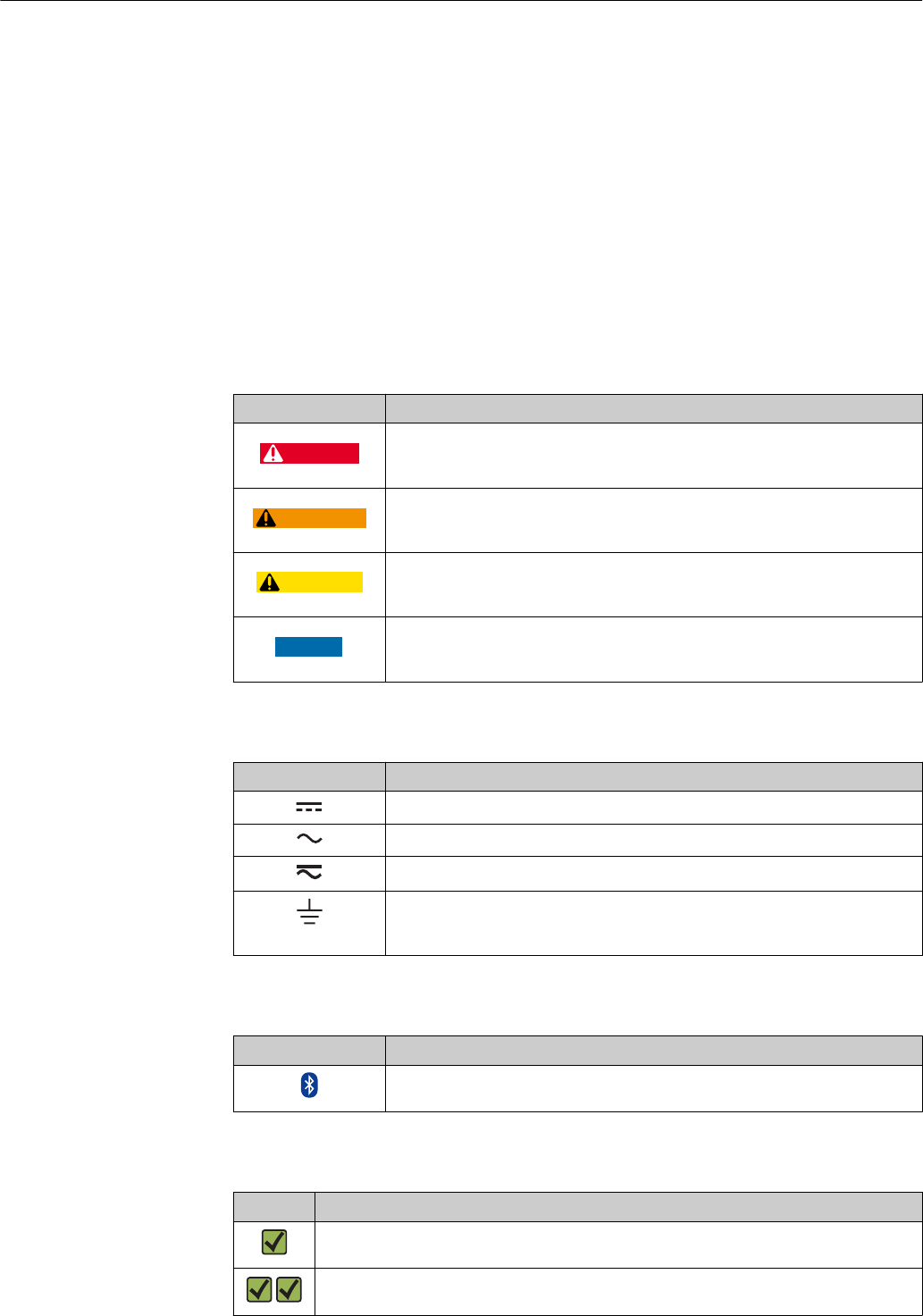
1.2.1 Safety symbols
Symbol Meaning
DANGER
DANGER!
This symbol alerts you to a dangerous situation. Failure to avoid this situation will
result in serious or fatal injury.
WARNING
WARNING!
This symbol alerts you to a dangerous situation. Failure to avoid this situation can
result in serious or fatal injury.
CAUTION
CAUTION!
This symbol alerts you to a dangerous situation. Failure to avoid this situation can
result in minor or medium injury.
NOTICE
NOTE!
This symbol contains information on procedures and other facts which do not result in
personal injury.
1.2.2 Electrical symbols
Symbol Meaning
Direct current
Alternating current
Direct and alternating current
Ground connection
A grounded terminal which, as far as the operator is concerned, is grounded via a
grounding system.
1.2.3 Communication symbols
Symbol Meaning
Bluetooth
Wireless data transmission between devices over a short distance.
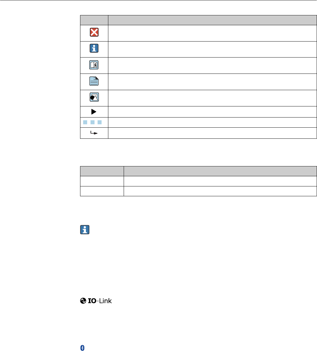
1.2.4 Symbols for certain types of information
Symbol Meaning
Permitted
Procedures, processes or actions that are permitted.
Preferred
Procedures, processes or actions that are preferred.
Picomag IO-Link About this document
Endress+Hauser 5
Symbol Meaning
Forbidden
Procedures, processes or actions that are forbidden.
Tip
Indicates additional information.
Reference to documentation
A
Reference to page
Reference to graphic
Notice or individual step to be observed
1.
,
2.
,
3.
… Series of steps
Result of a step
1.2.5 Symbols in graphics
Symbol Meaning
1, 2, 3, ... Item numbers
A, B, C, ... Views
1.3 Documentation
For an overview of the scope of the associated Technical Documentation, refer to the
following:
• The W@M Device Viewer: Enter the serial number of the measuring device
(www.endress.com/deviceviewer)
• The Endress+Hauser Operations App: Enter the serial number of the measuring
device or scan the 2-D matrix code on the measuring device.
1.4 Registered trademarks
®
Is a registered trademark. It may only be used in conjunction with products and services by
members of the IO-Link Community or by non-members who hold an appropriate license.
For more detailed information on the use of IO-Link, please refer to the rules of the IO-
Link Community at: www.io.link.com.
Bluetooth® wireless technology
®
The Bluetooth® word mark and logos are registered trademarks owned by the Bluetooth
SIG, Inc. and any use of such marks by Endress+Hauser is under license.
Apple®
Apple, the Apple logo, iPhone, and iPod touch are trademarks of Apple Inc., registered in
the U.S. and other countries. App Store is a service mark of Apple Inc.
Android®
Android, Google Play and the Google Play logo are trademarks of Google Inc.

Basic safety instructions Picomag IO-Link
6 Endress+Hauser
2 Basic safety instructions
2.1 Requirements for the personnel
The personnel for installation, commissioning, diagnostics and maintenance must fulfill
the following requirements:
‣Trained, qualified specialists must have a relevant qualification for this specific function
and task.
‣Are authorized by the plant owner/operator.
‣Are familiar with federal/national regulations.
‣Before starting work, read and understand the instructions in the manual and
supplementary documentation as well as the certificates (depending on the
application).
‣Follow instructions and comply with basic conditions.
The operating personnel must fulfill the following requirements:
‣Are instructed and authorized according to the requirements of the task by the facility's
owner-operator.
‣Follow the instructions in this manual.
2.2 Designated use
Application and media
The measuring device described in these Brief Operating Instructions is intended only for
flow measurement of liquids with a minimum conductivity of 20 µS/cm.
To ensure that the measuring device remains in proper condition for the operation time:
‣Use the measuring device only for media against which the process-wetted materials
are adequately resistant.
Incorrect use
Non-designated use can compromise safety. The manufacturer is not liable for damage
caused by improper or non-designated use.
LWARNING
Danger of breakage due to corrosive or abrasive fluids!
‣Verify the compatibility of the process fluid with the sensor material.
‣Ensure the resistance of all fluid-wetted materials in the process.
‣Keep within the specified pressure and temperature range.
Residual risks
LWARNING
The electronics and the medium may cause the surfaces to heat up. This presents a
burn hazard!
‣For elevated fluid temperatures, ensure protection against contact to prevent burns.
2.3 Workplace safety
For work on and with the device:
‣Wear the required personal protective equipment according to federal/national
regulations.
For welding work on the piping:
‣Do not ground the welding unit via the measuring device.

Picomag IO-Link Basic safety instructions
Endress+Hauser 7
2.4 Operational safety
Risk of injury!
‣Operate the device in proper technical condition and fail-safe condition only.
‣The operator is responsible for interference-free operation of the device.
2.5 Product safety
This measuring device is designed in accordance with good engineering practice to meet
state-of-the-art safety requirements, has been tested, and left the factory in a condition in
which it is safe to operate.
It meets general safety standards and legal requirements. It also complies with the EU
directives listed in the device-specific EU Declaration of Conformity. Endress+Hauser
confirms this by affixing the CE mark to the device.
2.6 IT security
We only provide a warranty if the device is installed and used as described in the
Operating Instructions. The device is equipped with security mechanisms to protect it
against any inadvertent changes to the device settings.
IT security measures in line with operators' security standards and designed to provide
additional protection for the device and device data transfer must be implemented by the
operators themselves.
2.7 Device-specific IT security
2.7.1 Access via the SmartBlue App
Two access levels (user roles) are defined for the device: the Operator user role and the
Maintenance user role. The Maintenance user role is the default setting.
If a user-specific access code is not defined (in the Set access code parameter), the default
setting 0000 continues to apply and the Maintenance user role is automatically enabled.
The device's configuration data are not write-protected and can be edited at all times.
If a user-specific access code has been defined (in the Set access code parameter), all the
parameters are write-protected and the device is accessed with the Operator user role. The
previously defined access code must first be entered again before the Maintenance user
role is enabled and all the parameters can be write-accessed.
2.7.2 Access via Bluetooth® wireless technology
Signal transmission via Bluetooth® wireless technology uses a cryptographic
technique tested by the Fraunhofer Institute
• The device is not visible via Bluetooth® wireless technology without the SmartBlue App.
• Only one point-to-point connection is established between a sensor and a smartphone or
tablet.
• The Bluetooth® wireless technology interface can be disabled via SmartBlue.
Incoming acceptance and product identification Picomag IO-Link
8 Endress+Hauser
3 Incoming acceptance and product
identification
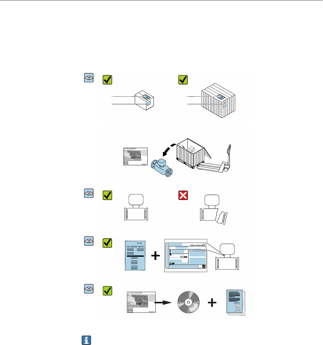
3.1 Incoming acceptance
A0028673
1
2
1
2
Are the order codes on the
delivery note (1) and the
product sticker (2) identical?
A0028673
Are the goods undamaged?
A0028673
Order code:
Ser. no.:
Ext. ord. cd.:
ii
Date:
Do the nameplate data
match the ordering
information on the delivery
note?
A0028673
Is the CD-ROM with the
Technical Documentation
(depends on device version)
and documents present?
• If one of the conditions is not satisfied, contact your Endress+Hauser Sales Center.
• Depending on the device version, the CD-ROM might not be part of the delivery!
The Technical Documentation is available via the Internet or via the Endress+Hauser
Operations App, see the "Product identification" section .
3.2 Product identification
The following options are available for identification of the measuring device:
• The device label
• Order code with breakdown of the device features on the delivery note
• Enter the serial number on the device label in W@M Device Viewer
(www.endress.com/deviceviewer): all the information about the measuring device is
displayed.
• Enter the serial number on the device label into the Endress+Hauser Operations App or
scan the 2-D matrix code (QR code) on the measuring device with the Endress+Hauser
Operations App: all the information about the measuring device is displayed.

Picomag IO-Link Incoming acceptance and product identification
Endress+Hauser 9
3.2.1 Symbols on measuring device
Symbol Meaning
WARNING!
This symbol alerts you to a dangerous situation. Failure to avoid this situation can result in serious
or fatal injury.
Reference to documentation
Refers to the corresponding device documentation.

Storage and transport Picomag IO-Link
10 Endress+Hauser
4 Storage and transport
4.1 Storage conditions
Observe the following notes for storage:
‣Store in the original packaging to ensure protection from shock.
‣Store in a dry place.
‣Do not store outdoors.
Storage temperature→ 34
4.2 Transporting the product
Transport the measuring device to the measuring point in the original packaging.
Do not remove protective covers or caps installed on process connections. They
prevent mechanical damage to the sealing surfaces and contamination in the
measuring tube.
4.3 Packaging disposal
All packaging materials are environmentally friendly and 100% recyclable:
Carton in accordance with European Packaging Directive 94/62EC; recyclability is
confirmed by the affixed RESY symbol.

Picomag IO-Link Installation
Endress+Hauser 11
5 Installation
5.1 Installation conditions
5.1.1 Mounting position
Mounting location
h
A0032998
Preferably install the sensor in an ascending pipe, and ensure a sufficient distance to the
next pipe elbow: h ≥ 2 × DN
Inlet and outlet runs
Observe the following inlet and outlet runs to comply with accuracy specifications:
≥ 3 × DN ≥ 1 × DN
A0032997
Installation dimensions: information on the dimensions and installed lengths of the
device → 35
5.2 Mounting the measuring device
LWARNING
Burn hazard!
If medium temperatures or ambient temperatures exceed 50 °C, areas of the housing can
heat to over 65 °C.
‣Safeguard the housing so that it cannot be touched accidentally.


Picomag IO-Link Electrical connection
Endress+Hauser 13
6 Electrical connection
6.1 Connection conditions
6.1.1 Requirements for connecting cables
National regulations and standards apply.
Connecting cable M12 × 1 A-coded
Conductor cross-section At least 0.12 mm2 (AWG26)
Temperature range –10 to +80 °C (+14 to +176 °F)
Degree of protection IP65/67
6.1.2 Pin assignment, device plug
A
2
1
4
3
1
2
3
4
+
-
E
A
B
B
A
L+
L-
OUT2
OUT1
A0033004
A Socket
B Connector
Pin Assignment Description
1 L+ Supply voltage + (18 to 30 VDC/max. 3 W)
2 Output 2 Output 2, can be configured independently of output 1
3 L- Supply voltage -
4 Output 1 Output 1, can be configured independently of output 2

Electrical connection Picomag IO-Link
14 Endress+Hauser
Switch/pulse output configuration version
Configurable switching behavior:
pnp 1) npn 2)
1
2
3
4
B
A
L+
L-
A0033005
A Socket
B Connector
L+ Supply voltage +
L- Supply voltage -
1
2
3
4
B
A
L+
L-
A0033006
A Socket
B Connector
L+ Supply voltage +
L- Supply voltage -
The load is switched to high side L+. The maximum
load current is 250 mA. The output is overload-
resistant.
The load is switched to low side L-. The maximum load
current is 250 mA. The output is overload-resistant.
1) positive negative positive (high side switch)
2) negative positive negative (low side switch)
Current output configuration version
1
2
3
4
B
A
L+
L-
A0033007
1 Current output, active, 4 to 20 mA
A Socket
B Connector
L+ Supply voltage +
L- Supply voltage -
The current flows from the output to L-. The maximum load may not exceed 500 Ω. A
bigger load distorts the output signal.
Voltage output configuration version
1
2
3
4
B
A
L+
L-
A0033007
2 Voltage output, active, 2 to 10 V
A Socket
B Connector
L+ Supply voltage +
L- Supply voltage -

Picomag IO-Link Electrical connection
Endress+Hauser 15
The voltage from the output applies to L-. The load must be at least 500 Ω. The output is
overload-resistant.
Status input configuration version
• 15 V (switch-on threshold)
• 5 V (switch-off threshold)
1
2
3
4
B
A
L+
L-
==
A0033008
3 Status input
A Socket
B Connector
L+ Supply voltage +
L- Supply voltage -
Internal resistance: 7.5 Ω
IO-Link configuration version
Option only available for output 1 in the Output 1→ 22 submenu
The measuring device has a Type 2 IO-Link communication interface with a second IO
function on pin 2 and with a baud rate of 38 400. This requires an IO-Link-enabled module
(IO-Link Master) for operation. The IO-Link communication interface allows direct access
to the process and diagnostics data.
6.2 Connecting the measuring device
NOTICE
The measuring device may only be installed by properly trained technicians.
‣Comply with national and international regulations regarding the installation of
electrotechnical systems.
‣Power supply according to EN 50178, SELV, PELV or Class 2.
1. De-energize the system.
2. Connect the measuring device via the connector.
3.
1
A0033003
In the case of non-grounded pipes:
The device must be grounded using the ground terminal accessory.

Electrical connection Picomag IO-Link
16 Endress+Hauser
6.3 Post-connection check
Are cables or the device undamaged (visual inspection)?
Do the cables have adequate strain relief?
Is the connector connected correctly?
Does the supply voltage match the specifications on the measuring device?
Is the pin assignment of the connector correct?
Is the potential equalization established correctly?

Picomag IO-Link Operation options
Endress+Hauser 17
7 Operation options
7.1 Access to the operating menu via the SmartBlue App
The device can be operated and configured via the SmartBlue App. In this case, the
connection is established via the Bluetooth® wireless technology interface.
Supported functions
• Device selection in Live List and access to the device (login)
• Configuration of the device
• Access to measured values, device status and diagnostics information
The SmartBlue App is available for free download for Android devices (Google Playstore)
and iOS devices (iTunes Apple Shop) : Endress+Hauser SmartBlue
Directly to the app with the QR code:
A0033202
System requirements
• Devices with iOS:
– iPhone 4S or higher, from iOS9.0
– iPad2 or higher, from iOS9.0
– iPod Touch 5th generation or higher, from iOS9.0
• Devices with Android:
Android 4.4 KitKat or higher
Download the SmartBlue App:
1. Install and start the SmartBlue App.
A Live List shows all the devices available.
The list displays the devices with the configured tag name. The default setting for
the tag name is EH_DMA_XYZZ (XYZZ = the last 7 digits of the device serial
number).
2. Select the device from the Live List.
The Login dialog box opens.
Logging in:
3. Enter the user name: admin.
4. Enter the initial password: serial number of the device.
5. Confirm your entry.
The main menu opens.
Navigate through the various items of information about the device: swipe the screen
to the side.

System integration Picomag IO-Link
18 Endress+Hauser
8 System integration
The measuring device has an IO-Link communication interface. The IO-Link interface
allows direct access to process and diagnostics data and enables the user to configure the
measuring device on the fly.
Properties:
• IO-Link Specification: Version 1.1
• IO-Link Smart Sensor Profile 2nd Edition
• SIO mode: yes
• Speed: COM2 (38.4 kBaud)
• Minimum cycle time: depends on device and is defined by a number of factors including
the process data to be transmitted.
10 ms
• Process data width: depends on device and is defined by a number of factors including
the process data to be transmitted.
80 bit
• IO-Link data storage: yes
• Block configuration: no
More information on IO-Link is available at www.io-link.com
8.1 Overview of device description files
Current version data for the device
Firmware version 01.00.zz • On the title page of the Operating instructions
• On the device label
• Parameter Firmware version System → Device info →
Firmware version
Release date of firmware
version
09.2017 ---
Profile version • 1.1
• Smart Sensor
Profile
---
8.2 Device master file
In order to integrate field devices into a digital communication system, the IO-Link system
needs a description of the device parameters, such as output data, input data, data format,
data volume and supported transmission rate.
These data are available in the device master file (IODD 1)) which is provided to the IO-Link
Master via generic modules when the communication system is commissioned.
The IODD can be downloaded as follows:
• Endress+Hauser: www.endress.com
• IODDfinder: ioddfinder.io-link.com
1) IO Device Description

Picomag IO-Link Commissioning
Endress+Hauser 19
9 Commissioning
9.1 Switching ON the measuring device
Once the supply voltage has been switched on, the measuring device adopts the normal
mode after a maximum of 5 s. During the start-up phase, the outputs are in the same state
as the measuring device in the switched-off state.
9.2 Configuring the measuring device
Overview of the operating menu
Application
▸ Measured values → 27
▸ System units → 21
▸ Process
▸ Sensor → 21
▸ Output 1 → 22
▸ Output 2 → 22
System
▸ Device info → 32
▸ Display → 20
▸ Bluetooth configuration → 28
▸ Administration → 28
Diagnostics
▸ Actual diagnostics → 32
▸ Simulation 1 → 26

Commissioning Picomag IO-Link
20 Endress+Hauser
9.2.1 Configuring the display
The Display submenu contains all the parameters that can be configured for the
configuration of the onsite display.
Navigation
Menu: "System" → Display
Parameter overview with brief description
Parameter Description Selection/input Factory setting
Format display Select how measured values
are shown on the display.
Display value 1st line + display value 2nd line:
• Volume flow + temperature
• Volume flow + totalizer
• Temperature + totalizer
Volume flow +
temperature
Rotation display Select local display rotation. • Auto (automatic)
• The display rotates automatically depending on the installation position
Auto
• 0°
• Can be read in the horizontal installation position with flow from left to right
A
A0033013
• 90°
• Can be read in the vertical installation position with flow from bottom to top
A
A0033014
• 180°
• Can be read in the horizontal installation position with flow from right to left
A
A0033015
• 270°
• Can be read in the vertical installation position with flow from top to bottom
A
A0033016
Backlight Set the intensity of the
backlighting.
0 to 100 % 50 %

Picomag IO-Link Commissioning
Endress+Hauser 21
9.2.2 Configuring system units
In the System units submenu, you can configure the units of all measured values.
Navigation
Menu: "Application" → System units
Parameter overview with brief description
Parameter Description Options Factory setting
Volume flow unit Select volume flow unit. • l/s, m³/h, l/min
• gal/min (us)
l/min
Volume unit Select volume unit. • ml, l, m³
• fl. oz (us), gal (us)
ml
Temperature unit Select temperature unit. • °C
• °F
°C
Totalizer unit Select totalizer unit. • l, m³
• 1 000 l, 1 000 m3
• fl. oz (us), gal (us)
• 1 000 gal (us)
m³
9.2.3 Setting the installation direction and measurement
The Sensor submenu contains parameters for specific settings of the measuring device.
Navigation
Menu: "Application" → Sensor
Parameter overview with brief description
Parameter Description Selection/input Factory setting
Installation
direction
Select the installation
direction.
• Flow in arrow direction (forwards)
Positive flow measurement in the direction of the arrow.
• Flow against arrow direction (backwards)
Positive flow measurement in the opposite direction of the
arrow.
Flow in arrow direction (forwards)
On value Enter the on value for low
flow cut off.
Positive floating point number
A flow measured value that is less than the value of the on
value forces the display to zero. In the event of plant
downtime, this prevents the totalizer from continuing to
totalize even though there is no flow.
Depends on the nominal diameter:
DN 15 (½"):
0.4 l/min (0.1 gal/min)
DN 20 (¾"):
0.75 l/min (0.2 gal/min)
DN 25 (1"):
1.2 l/min (0.3 gal/min)
DN 50 (2"):
5.0 l/min (1.3 gal/min)
Damping Enter the time constant for
damping the flow
measured value.
0 to 10 s 0 s

Commissioning Picomag IO-Link
22 Endress+Hauser
9.2.4 Configuring the IO modules
The measuring device has two signal inputs or signal outputs that can be configured
independently of one another:
• Current output→ 22
• Pulse output→ 22
• Switch output→ 23
• Voltage output→ 24
• Status input → 25
Navigation
Menu: "Application" → Output 1
Menu: "Application" → Output 2
Parameter overview with brief description
Parameter Description Options Factory setting
I/O module 1 type Select the operating mode of output 1. • Pulse output
• Current output
• Switch output
• Voltage output
• Digital input
• IO-Link
• Off
IO-Link
I/O module 2 type Select the operating mode of output 2. • Pulse output
• Current output
• Switch output
• Voltage output
• Digital input
• Off
Switch output
Configuring the current output
The Current output submenu contains all the parameters that must be configured for the
configuration of the current output.
The output is used to output process variables by analog means in the form of a 4-20 mA
current.
Navigation
Menu: "Application" → Output 1 → Current output
Menu: "Application" → Output 2 → Current output
Parameter overview with brief description
Parameter Description Selection/input Factory setting
Assign current output Select process variable for current output. • Off
• Volume flow
• Temperature
Volume flow
4 mA value Enter 4 mA value. Floating point number with sign 0 l/min
20 mA value Enter 20 mA value. Floating point number with sign Depends on the nominal diameter:
DN 15 (½"): 25 l/min (6.6 gal/min)
DN 20 (¾"): 50 l/min (13.2 gal/min)
DN 25 (1"): 100 l/min (26.4 gal/min)
DN 50 (2"): 750 l/min (198.1 gal/min)
Configuring the pulse output
The Pulse output submenu contains all the parameters that must be configured for the
configuration of the pulse output.
Navigation

Picomag IO-Link Commissioning
Endress+Hauser 23
Menu: "Application" → Output 1 → Pulse output
Menu: "Application" → Output 2→ Pulse output
Parameter overview with brief description
Parameter Description Entry Factory setting
Value per pulse Enter the value for the pulse output. Floating point number with sign Depends on the nominal diameter:
DN 15 (½"): 0.5 l/min (0.1 gal/min)
DN 20 (¾"): 1.0 l/min (0.3 gal/min)
DN 25 (1"): 2.0 l/min (0.5 gal/min)
DN 50 (2"): 10.0 l/min (2.6 gal/min)
The current pulse repetition frequency is calculated from the current flow and the
configured pulse value:
Pulse repetition frequency = flow/pulse value
Example
• Flow: 300 l/min (79.25 gal/min)
• Pulse value: 0.001 l
• Pulse repetition frequency = 5 000 Pulse/s
• The maximum pulse repetition frequency is 10 kHz.
The Pulse output only outputs positive flow components in the set installation direction.
Negative flow components are ignored and not balanced.
Configuring the switch output
The Switch output submenu contains all the parameters that must be configured for the
configuration of the switch output.
Navigation
Menu: "Application" → Output 1 → Switch output
Menu: "Application" → Output 2 → Switch output
Parameter overview with brief description
Parameter Description Selection/input Factory setting
Polarity Select the switching
behavior.
• NPN (low-side-switch)
Switches load to low side to L-
• PNP (high-side-switch)
Switches load to high side to L+
PNP (high-side-switch)
Switch output
function
• Diagnostic behavior
The output switches when an event with the status signal F occurs
• Off
The switch output is permanently switched off (open, non-conductive).
• On
The switch output is permanently switched on (closed, conductive).
• Limit volume flow
Indicates if a specified limit value has been reached for the process variable.
• Limit temperature
Indicates if a specified limit value has been reached for the process variable.
• Range volume flow
• Range temperature
• Empty pipe detection
Output switches on when empty pipe detection is active.
Diagnostic behavior
Switch-on value Enter the measured value
for the switch-on value.
Floating point number with sign Country-specific:
• 1 000 m³/h
• 1 000 gal/min (us)
Switch-off value Enter the measured value
for the switch-off value.
Floating point number with sign Country-specific:
• 1 000 m³/h
• 1 000 gal/min (us)

Commissioning Picomag IO-Link
24 Endress+Hauser
Hysteresis switched on Hysteresis switched off
1
0
A
B
t
C
1.1
1.2
Q / T
A0034163
1.1 Input variables
1.2 Switch output
A Switch-on point
B Switch-off value
C Hysteresis
Q / T
1
0
A
B
t
C
2.1
2.2
A0034164
2.1 Input variables
2.2 Switch output
A Switch-on point
B Switch-off value
C Hysteresis
Range switched on Range switched off
Q / T
1
0
A
t
D D
3.1
3.2
B
B
A
A0034165
3.1 Input variables
3.2 Switch output
A On-value (lower range limit)
B Off-value (upper range limit)
D Window
Q / T
1
0
A
B
t
D D
4.1
4.2
A
B
A0034166
4.1 Input variables
4.2 Switch output
A On-value (lower range limit)
B Off-value (upper range limit)
D Window
Configuring the voltage output
The Voltage output submenu contains all the parameters that must be configured for the
configuration of the voltage output.
Navigation
Menu: "Application" → Output 1 → Voltage output
Menu: "Application" → Output 2 → Voltage output
Parameter overview with brief description
Parameter Description Selection/input Factory setting
Assign voltage output Select process variable for voltage output. • Off
• Volume flow
• Temperature
Volume flow
2 V value Enter the lower-range value. Floating point number with sign 0 l/min
10 V value Enter the upper-range value. Floating point number with sign Depends on the nominal diameter:
DN 15 (½"): 25 l/min (6.6 gal/min)
DN 20 (¾"): 50 l/min (13.2 gal/min)
DN 25 (1"): 100 l/min (26.4 gal/min)
DN 50 (2"): 750 l/min (198.1 gal/min)

Picomag IO-Link Commissioning
Endress+Hauser 25
Unidirectional flow measurement (Q)
A = 0 B
Q
mA / V
20 10
16 8
12
8
4
6
4
2
A0032995
A Lower-range value = 0
B Upper-range value
Q Flow
• Current I or voltage U are interpolated linearly between the lower-range value (A) and
upper-range value (B).
• The output range ends at 20.5 mA or 10.5 V.
Bidirectional flow measurement (Q) or temperature measurement (T)
0B
Q
mA / V
20 10
16 8
8
4
4
2
A
12 6
A0032996
A Lower value
B Upper-range value
Q Flow
• Current I or voltage U are interpolated linearly between the lower-range value (A) and
upper-range value (B).
• Rather than having a hard upper and lower limit, the output range ends at 20.5 mA or
10.5 V at the top end, and at 3.8 mA or 1.9 V at the bottom end.
Configuring the status input
The Digital input submenu contains all the parameters that must be configured for the
configuration of the digital input.
The input is used to control an action with an external voltage signal. The minimum pulse
duration is 100 ms.
Navigation
Menu: "Application" → Output 1 → Digital input

Commissioning Picomag IO-Link
26 Endress+Hauser
Menu: "Application" → Output 2 → Digital input
Parameter overview with brief description
Parameter Description Options Factory setting
Active level Select the switching behavior of the digital input. • High
Input reacts to high level
• Low
Input reacts to low level
High
Assign status input Select process variable for status input. • Off
• Reset totalizer
Resets the totalizer
• Flow override
– Flow measured value = 0
– Does not affect the temperature measurement
Reset totalizer
9.2.5 Simulation
The Simulation submenu enables you to simulate, without a real flow situation, different
process variables in the process and the device alarm behavior and to verify downstream
signal chains (switching of valves or closed-control loops).
Navigation
Menu: "Diagnostics" → Simulation 1
Parameter overview with brief description
Parameter Description Selection/input Factory
setting
Simulation process
variable
Activate the simulation of process
variables.
• Off
Simulation is deactivated.
• On
Simulation is activated.
Deactivate the simulation again once the test has
been performed.
Off
Volume flow value Enter the value for volume flow
simulation.
Positive floating point number –
Temperature value Enter the value for temperature
simulation.
Positive floating point number –

Picomag IO-Link Operation
Endress+Hauser 27
10 Operation
10.1 Reading measured values
You can read all measured values using the Measured values submenu.
Navigation
Menu: "Application" → Measured values
Parameter overview with brief description
Parameter Description Display/options Factory setting
Volume flow Displays the volume flow currently measured. Floating point number with sign –
Temperature Displays the temperature currently measured. Floating point number with sign –
Totalizer Displays the current totalizer counter value.
The totalizer continuously totalizes only positive flow measured values in the set
flow direction. Negative components are not counted.
Floating point number with sign –
Reset totalizer Reset the totalizer. • Cancel
The totalizer is not reset.
• Reset + totalize
The totalizer is reset.
Cancel

Operation Picomag IO-Link
28 Endress+Hauser
10.2 Configuring Bluetooth
The Bluetooth configuration submenu contains all the parameters to configure the
Bluetooth connection.
Navigation
Menu: "System" → Bluetooth configuration
Parameter overview with brief description
Parameter Description Options Factory
setting
Bluetooth Enable or disable the Bluetooth® wireless technology
interface.
If the interface is disabled, it can only be re-enabled by
tapping the device.
• Disable
– Disable the interface.
– The connection to the measuring device is torn down.
• Enable
– Enable the interface.
– The connection to the measuring device is established.
Enable
10.3 Administration
The Administration submenu contains all the parameters that can be used for the
administration of the device.
Navigation
Menu: "System" → Administration
Parameter overview with brief description
Parameter Description Entry/selection/display Factory setting
Set access code Enter a user-specific access code to restrict write access to
parameters.
Max. 4-digit character string comprising
numbers, letters and special characters
0000
Enter access code Enter the access code.
Restrict write access to parameters in order to protect the
device configuration from unauthorized modification.
Max. 4-digit character string comprising
numbers, letters and special characters
0000
Device reset Reset the entire device configuration or some of the
configuration to a defined state.
• Cancel
• To factory defaults
• Restart device
Cancel
Access status tooling Displays the access status. • Operator
• Maintenance
Maintenance

Picomag IO-Link Diagnostics and troubleshooting
Endress+Hauser 29
11 Diagnostics and troubleshooting
11.1 General troubleshooting
For local display
Error Possible causes Solution
Local display dark and no output
signals
Supply voltage does not match the
value indicated on the nameplate.
Apply the correct supply voltage
→ 34.
The polarity of the supply voltage is
wrong.
Correct the polarity.
The connecting cables are not
connected correctly.
Check the cable connection and
correct if necessary.
For output signals
Error Possible causes Solution
Device shows correct value on local
display, but signal output is
incorrect, though in the valid range.
Configuration error Check and correct the parameter
configuration.
Device measures incorrectly. Configuration error or device is
operated outside the application.
1. Check and correct parameter
configuration.
2. Observe limit values specified in
the "Technical Data".
For access
Error Possible causes Solution
No connection established via
Bluetooth
Bluetooth communication is
disabled
1. Check whether the Bluetooth
logo is visible on the local display or
not.
2. Re-enable Bluetooth
communication by tapping the
device.
No communication with device via
SmartBlue App
No Bluetooth connection Enable Bluetooth function on
smartphone or tablet.
The device is already connected
with another smartphone/tablet.
Login via SmartBlue App not
possible
Device is being put into operation
for the first time
Enter initial password (device serial
number) and change.
Device cannot be operated via
SmartBlue App
Incorrect password entered Enter correct password.
Password forgotten Contact Endress+Hauser Service.
Diagnostics and troubleshooting Picomag IO-Link
30 Endress+Hauser
11.2 Diagnostic information on local display
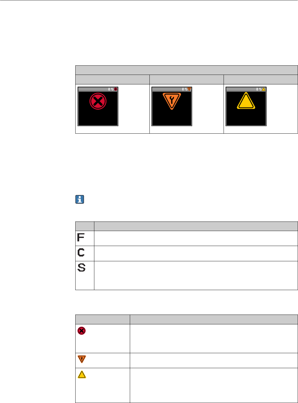
11.2.1 Diagnostic message
Faults detected by the self-monitoring system of the measuring device are displayed as a
diagnostic message in alternation with the operational display.
Diagnostic message
Alarm Function check Warning
Xxxxxxx
F 1 8 0
T E M P . C I R C . F A I L .
A0033011
Xxxxxxx
C 4 4 6
I / O 1 O V E R L O A D
A0033010
Xxxxxxx
S 9 6 2
E M P T Y P I P E
?
?
A0033009
If two or more diagnostic events are pending simultaneously, only the message of the
diagnostic event with the highest priority is shown.
Status signals
The status signals provide information on the state and reliability of the device by
categorizing the cause of the diagnostic information (diagnostic event).
The status signals are categorized according to VDI/VDE 2650 and NAMUR
Recommendation NE 107: F = Failure, C = Function Check, S = Out of Specification, M
= Maintenance Required
Symbol Meaning
Failure
An operating error has occurred. The measured value is no longer valid.
Function check
The device is in simulation mode.
Out of specification
The device is being operated:
• Outside its technical specification limits (e.g. outside the process temperature range)
• Outside of the configuration carried out by the user (e.g. maximum flow in parameter 20 mA value)
Diagnostic behavior
Diagnostic message Meaning
Alarm
• Measurement is interrupted.
• Signal outputs and totalizers assume the defined alarm condition.
• A diagnostic message is generated.
Function check
Process measured values are simulated to test the outputs/wiring.
?
Warning
• Measurement is resumed.
• Measuring operation with limited accuracy
• The signal outputs and totalizers are not affected.
• A diagnostic message is generated.

Picomag IO-Link Diagnostics and troubleshooting
Endress+Hauser 31
Diagnostics behavior of outputs
Output Diagnostic behavior
Switch output • Setting for reporting events with the status signal F
• Switch output is switched on if an event occurs
• No further response to events with other status signals
Pulse output • Pulse output stops if events with the status signal F occur
• No further response to events with other status signals
Totalizer • Totalizing stops if events with the status signal F occur
• No further response to events with other status signals
Current output • 3.5 mA output to report events with the status signal F
• No further response to events with other status signals
Voltage output • 1.75 V output to report events with the status signal F
• No further response to events with other status signals
IO-Link • All events reported to the Master
• Events read and processed further by the Master
11.3 Overview of diagnostic events
Diagnostic
event Event text Reason Remedial measures Status signal [ex-
factory]
181 Coil. circ. fail. Coil/frequency failure
Coil current PWM
outside tolerance range
Replace the measuring
device.
F
180 Temp. circ.
fail.
Temperature sensor
open circuit/short-
circuit
Replace the measuring
device.
F
201 Device fail. No communication to
ADC/Nordic/BMA
Replace the measuring
device.
F
283 Memory fail. CRC failure Reset to factory settings. F
446 I/O 1
overload
Overload at output 1 Increase load impedance. C
447 I/O 2
overload
Overload at output 2 Increase load impedance. C
485 Simulation
act.
Measured value
simulation active (via
remote configuration)
– C
453 Flow override Flow override active (via
auxiliary input)
– C
441 I-Out 1 range I-output 1 at range limit Adjust parameter or process. S
444 U-Out 1
range
U-output 1 at range
limit
Adjust parameter or process. S
443 P-Out 1
range
P-output 1 at range
limit
Adjust parameter or process. S
442 I-Out 2 range I-output 2 at range limit Adjust parameter or process. S
445 U-Out 2
range
U-output 2 at range
limit
Adjust parameter or process. S
448 P-Out 2
range
P-output 2 at range
limit
Adjust parameter or process. S
962 Empty pipe Pipe is completely or
partially empty
Adjust the process. S

Diagnostics and troubleshooting Picomag IO-Link
32 Endress+Hauser
Diagnostic
event Event text Reason Remedial measures Status signal [ex-
factory]
834 Temperat.
range
Medium temperature
outside the permitted
range
Adjust the process. S
841 Flow range Flow rate outside the
permitted range
Adjust the process. S
11.4 Pending diagnostic events
Navigation
Menu: "Diagnostics" → Diagnostics
Parameter overview with brief description
Parameter Prerequisite Description Display
Actual
diagnostic
A diagnostic event has
occurred.
Displays the current diagnostic event along with the diagnostic
information.
If two or more messages occur simultaneously, the message with the
highest priority is shown on the display.
Symbol for diagnostic
behavior, diagnostic code
and short message.
11.5 Device information
The Device info submenu contains all parameters that display different information for
device identification.
Navigation
Menu: "System" → Device info
Parameter overview with brief description
Parameter Description Display
Device name Displays the name of the measuring device. Picomag
Device tag Shows name of measuring point. Max. 32 characters, such as letters, numbers or special characters (e.g. @,
%, /).
Serial number Displays the serial number of the measuring device. Max. 11-digit character string comprising letters and numbers.
Firmware version Displays the device firmware version installed. Character string in the format xx.yy.zz
Extended order code Displays the extended order code. Character string composed of letters, numbers and certain punctuation
marks (e.g. /).
11.6 Firmware history
Release
date
Firmware
version
Firmware
changes
Documentation type Documentation
09.2017 01.00.zz Original firmware Operating
Instructions
BA01697D/06/EN/01.17

Picomag IO-Link Accessories
Endress+Hauser 33
12 Accessories
Various accessories, which can be ordered with the device or subsequently from Endress
+Hauser, are available for the device. Detailed information on the order code in question is
available from your local Endress+Hauser sales center or on the product page of the
Endress+Hauser website: www.endress.com.

Technical data Picomag IO-Link
34 Endress+Hauser
13 Technical data
13.1 Input
Measured values • Volume flow
• Temperature
• Totalizer
Measuring range (upper-range value E) DN 15 (½"): 25 l/min (6.6 gal/min)
DN 20 (¾"): 50 l/min (13.2 gal/min)
DN 25 (1"): 100 l/min (26.4 gal/min)
DN 50 (2"):750 l/min (198.1 gal/min)
13.2 Output
Output Max. load
Current output 500 Ω
The load may not be any greater
Voltage output 500 Ω
The load resistance may not any smaller
Digital output (SmartBlue App) Bluetooth® wireless technology
The device has a Bluetooth® wireless technology interface and can be
operated and configured via the SmartBlue App.
• The range under reference conditions is 10 m (33 ft)
• Incorrect operation by unauthorized persons is prevented by means
of encrypted communication and password encryption.
• The Bluetooth® wireless technology interface can be deactivated.
Signal on alarm • Status signal (as per NAMUR Recommendation NE 107)
• Plain text display with remedial action
13.3 Power supply
Supply voltage range 18 to 30 VDC (SELV, PELV, Class 2)
Power consumption Max. 3 W (excluding outputs IO1 and IO2)
13.4 Performance characteristics
Volume flow measurement
Maximum measured error ±2 % o.r. ±0.5 % o.f.s.
Repeatability ±0.2 % o.r. (95% confidence interval, measuring time 30 s)
Response time The response time depends on the configuration (damping).
Medium temperature measurement
Maximum measured error ±2.5 °C
Repeatability ±0.5 °C (95% confidence interval, measuring time 30 s)
13.5 Installation
→ 11
13.6 Environment
Ambient temperature range –10 to +60 °C (+14 to +140 °F)
Storage temperature –25 to +85 °C (–13 to +185 °F)

Picomag IO-Link Technical data
Endress+Hauser 35
Degree of protection IP65/67
Shock resistance 20 g (11 ms) as per IEC/EN60068-2-27
Vibration resistance Acceleration up to 5 g (10 to 2 000 Hz) as per IEC/EN60068-2-6
Electromagnetic compatibility (EMC) In accordance with IEC/EN61326 and/or IEC/EN55011 (Class A)
13.7 Process
Medium temperature range –10 to +70 °C (+14 to +158 °F)
Medium properties Liquid, conductivity > 20 µS/cm
Pressure Max. 16 barrel
13.8 Mechanical construction
B
A
C D
E
F
G
H
I
= =
A0033012
Dimensions in SI units
DN
[mm]
A
[mm]
B
[mm]
C
[mm]
D
[mm]
E
[mm]
F
[mm]
G
[mm]
H
[mm]
I
[mm]
15, 20, 25 110 73 40.5 69.5 M12 × 1 43 ½"
¾"
1"
56 56
50 200 113 80 120 M12 × 1 58 2" 86 86
Dimensions in US units
DN
[in]
A
[in]
B
[in]
C
[in]
D
[in]
E
[in]
F
[in]
G
[in]
H
[in]
I
[in]
½, ¾, 1 4.33 2.87 1.59 2.74 M12 × 1 1.69 ½"
¾"
1"
2.20 2.20
2 7.87 4.45 3.15 4.72 M12 × 1 2.28 2" 3.39 3.39
Weight in SI units
DN
[mm]
Weight
[kg]
15 0.34
20 0.35
25 0.36
50 1.55

Technical data Picomag IO-Link
36 Endress+Hauser
Weight in US units
DN
[in]
Weight
[lbs]
½" 0.75
¾" 0.77
1" 0.79
2" 3.42
Materials
Component Material
Measuring tube PEEK
Electrodes, temperature sensor 1.4404/316L
Process connection 1.4404/316L
Housing 1.4404/316L
Seal FKM
Display window Polycarbonate
13.9 Operability
Onsite display The device has an onsite display:
28.56
23.6
l / min
°C
Xxxxxxx
1
2
3
4 5 6
A0032991
1 Tag name (configurable)
2 Measured variable 1 (configurable), with sign
3 Measured variable 2 (configurable), with sign
4 Active Bluetooth connection
5 Active I/O-Link connection
6 Device status
Display element
A maximum of 2 readings from the 3 measured variables (volume flow, temperature,
totalizer) can be displayed
Remote operation Via Bluetooth® wireless technology
Digital communication Via IO-Link
13.10 Certificates and approvals

Picomag IO-Link Technical data
Endress+Hauser 37
CE mark The measuring system is in conformity with the statutory requirements of the applicable
EU Directives. These are listed in the corresponding EU Declaration of Conformity along
with the standards applied.
Endress+Hauser confirms successful testing of the device by affixing to it the CE mark.
Radio approval The measuring device has radio approval.
For detailed information on the radio approval, see the Appendix → 38
Pressure Equipment
Directive
Devices not bearing this marking (PED) are designed and manufactured according to good
engineering practice. They meet the requirements of Art. 4, Par. 3 of the Pressure
Equipment Directive 2014/68/EU. The range of application is indicated in tables 6 to 9 in
Annex II of the Pressure Equipment Directive 2014/68/EC.
CULUS listing The measuring device is UL-listed.

Appendix Picomag IO-Link
38 Endress+Hauser
14 Appendix
14.1 Radio approvals
14.1.1 Europe
This device meets the requirements of the Telecommunications Directive RED
2014/53/EU:
• EN 300 328 V2.1.1
• EN 301 489-1 V1.9.2
• EN 301 489-17 V2.2.1
• EN 62311: 2008
14.1.2 Canada and USA
English
This device complies with Part 15 of the FCC Rules and with Industry Canada licence-
exempt RSS standard(s).
Operation is subject to the following two conditions:
• This device may not cause harmful interference, and
• This device must accept any interference received, including interference that may cause
undesired operation.
Changes or modifications made to this equipment not expressly approved by
Endress+Hauser Flowtec AG may void the user's authorization to operate this
equipment.
Français
Le présent appareil est conforme aux CNR d'industrie Canada applicables aux appareils
radio exempts de licence.
L'exploitation est autorisée aux deux conditions suivantes :
• L'appareil ne doit pas produire de brouillage, et
• L'utilisateur de l'appareil doit accepter tout brouillage radioélectrique subi, même si le
brouillage est susceptible d'en compromettre le fonctionnement.
Les changements ou modifications apportées à cet appareil non expressément
approuvée par Endress+Hauser Flowtec AG peut annuler l'autorisation de l'utilisateur
d'opérer cet appareil.
14.1.3 Other countries
Other national approvals are available on request.

Picomag IO-Link Index
Endress+Hauser 39
Index
A
About this document ..........................4
Accessories ................................ 33
Appendix ................................. 38
Application
Media .................................. 6
B
Basic safety instructions ....................... 6
Bidirectional flow measurement (Q) or temperature
measurement (T) ........................... 25
C
CE mark ................................ 7, 37
Commissioning ............................. 19
Configuring system units ......................21
Configuring the current output ................. 22
Configuring the display ....................... 20
Configuring the IO modules .................... 22
Configuring the measuring device ............... 19
Configuring the pulse output ................... 22
Configuring the status input ................... 25
Configuring the voltage output ................. 24
Connecting the measuring device ................15
Connection conditions ........................ 13
Current output configuration version ............. 14
Current version data for the device ...............18
D
Declaration of Conformity ...................... 7
Designated use .............................. 6
Device information .......................... 32
Device master file ........................... 18
Diagnostic behavior ..........................30
Diagnostic information on local display ........... 30
Diagnostic message ..........................30
Diagnostics and troubleshooting ................ 29
Dimensions in SI units ........................ 35
Dimensions in US units ....................... 35
Document function ........................... 4
Documentation .............................. 5
E
Electrical connection ......................... 13
F
Field of application
Residual risks .............................6
Firmware history ............................32
I
Identifying the measuring device ................. 8
Incoming acceptance .......................... 8
Inlet and outlet runs ......................... 11
Inspection
Received goods ............................8
Installation ................................ 11
Installation conditions ........................11
IO-Link configuration version .................. 15
M
Materials ................................. 36
Mounting location ...........................11
Mounting position ...........................11
Mounting the measuring device .................11
O
Operation ................................. 27
Operation options ........................... 17
SmartBlue App ...........................17
Operational safety ............................7
Overview of device description files .............. 18
Overview of diagnostic events .................. 31
Overview of the operating menu ................ 19
P
Packaging disposal .......................... 10
Pending diagnostic events ..................... 32
Pin assignment, device plug ....................13
Post-connection check ........................16
Pressure Equipment Directive .................. 37
Product safety ...............................7
R
Radio approval ............................. 37
Radio approvals .......................... 38
Reading measured values ......................27
Registered trademarks .........................5
Requirements for connecting cables .............. 13
Requirements for personnel .....................6
S
Setting the installation direction and measurement .. 21
Status input configuration version ............... 15
Status signals .............................. 30
Storage conditions ...........................10
Storage temperature ......................... 10
Switch/pulse output configuration version ......... 14
Switching ON the measuring device .............. 19
Symbols used ............................... 4
System integration .......................... 18
T
Technical data ..............................34
Certificates and approvals ...................36
Environment ............................ 34
Input .................................. 34
Installation ............................. 34
Mechanical construction ....................35
Operability ..............................36
Output .................................34
Performance characteristics ................. 34
Power supply ............................ 34
Process ................................ 35

Index Picomag IO-Link
40 Endress+Hauser
Temperature range
Storage temperature .......................10
Tools
Transport ...............................10
Transporting the measuring device .............. 10
Troubleshooting
General ................................ 29
U
Unidirectional flow measurement (Q) ............ 25
Using measuring device
Borderline cases ...........................6
Incorrect use ............................. 6
V
Voltage output configuration version ............. 14
W
W@M Device Viewer ......................... 8
Weight
Transport (notes) .........................10
Weight in SI units ........................... 35
Weight in US units .......................... 36
Workplace safety ............................ 6


www.addresses.endress.com