Endress and Hauser SE KG FG-FXA52X-32X Fieldgate FXA52X/32X series with GSM Module User Manual Promodo TI Test Dokument
Endress and Hauser GmbH and Co Fieldgate FXA52X/32X series with GSM Module Promodo TI Test Dokument
Exhibit 8 User Manual
TI369F/00/en
Technical Information
Fieldgate FXA320, FXA520
Gateways / Interfaces
Gateway for Remote Monitoring of Sensors and Actuators
via Web Browsers
Application
Fieldgates enable remote monitoring of connected 4...20
mA sensors/actuators, either via telephone lines
(analogue), Ethernet TCP/IP or mobile communications
(GSM). The measured data is web compatible (HTTP,
HTML, WML) and can, therefore, be analysed in the
web browser without additional software.
For remote diagnosis and remote configuration, HART
sensors are suitable in conjunction with FXA520.
Their integrated time control make Fieldgates suitable for
all applications in which more distant measuring points
have to be sporadically analysed. Configurable
monitoring of limit values with alarm signalling via e-
mail or SMS make it possible to react directly to changes
on-site.
The supported data transfer in XML format allows for
simple further analysis and processing of the measured
data, through to integration into complex planning
systems.
Your benefits
• Communication via modem, Ethernet or GSM/GPRS
• Uses standard Internet protocols
(TCP/IP, http)
• Simple configuration with web browsers without
additional software
• Visualisation via Internet/Intranet in the web browser
and/or WAP mobile phone
• Limit value monitoring with alarm signalling via e-mail
or SMS
• Synchronised time stamping of all measured values
• XML data transfer allows for simple further processing
of the measured data
FXA320
• Optionally, four binary inputs with event counter
function and frequency measurement
• Two 4...20 mA current inputs with integrated loop
power supply
• Selectable active/passive current input (for 2-wire and
4-wire devices)
• Integrated communication resistor (250 Ω) for
configuration via Commubox
FXA520
• Web server for remote monitoring of up to
30 measuring points
• Up to 4 measured values can be displayed per device
(HART)
• Intrinsically safe version [EEx ia]IIC for applications in
hazardous areas
• Remote diagnosis and remote configuration of
connected HART devices
• Applicable in 4...20 mA SIL 2 Loops (IEC 61508)

Fieldgate FXA320, FXA520
2Endress + Hauser
Table of contents
Applications. . . . . . . . . . . . . . . . . . . . . . . . . . . . . . . . . 3
Vendor Managed Inventory . . . . . . . . . . . . . . . . . . . . . . . . . . . . . 3
Remote maintenance of measuring equipment (FXA520 only) . . . . 3
Communication interface . . . . . . . . . . . . . . . . . . . . . . 4
Internet connection . . . . . . . . . . . . . . . . . . . . . . . . . . . . . . . . . . . 4
Ethernet . . . . . . . . . . . . . . . . . . . . . . . . . . . . . . . . . . . . . . . . . . . . 4
Telephone network (analogue) . . . . . . . . . . . . . . . . . . . . . . . . . . . 4
Mobile communications network (GSM) . . . . . . . . . . . . . . . . . . . . 5
GPRS support . . . . . . . . . . . . . . . . . . . . . . . . . . . . . . . . . . . . . . . . 5
Function and system design. . . . . . . . . . . . . . . . . . . . . 6
Measuring system . . . . . . . . . . . . . . . . . . . . . . . . . . . . . . . . . . . . . 6
Input . . . . . . . . . . . . . . . . . . . . . . . . . . . . . . . . . . . . . 10
Analogue 4...20 mA inputs . . . . . . . . . . . . . . . . . . . . . . . . . . . . . 10
RS-485 interface (FXA 520 only) . . . . . . . . . . . . . . . . . . . . . . . . 10
HART channel 1&2 (FXA 520 only) . . . . . . . . . . . . . . . . . . . . . . 11
Binary inputs (FXA 320 only) . . . . . . . . . . . . . . . . . . . . . . . . . . . 11
Output . . . . . . . . . . . . . . . . . . . . . . . . . . . . . . . . . . . . 11
Output signal . . . . . . . . . . . . . . . . . . . . . . . . . . . . . . . . . . . . . . . 11
Overvoltage category as per EN 61010 . . . . . . . . . . . . . . . . . . . . 11
Protection class . . . . . . . . . . . . . . . . . . . . . . . . . . . . . . . . . . . . . 11
Power supply. . . . . . . . . . . . . . . . . . . . . . . . . . . . . . . 12
Electrical connection . . . . . . . . . . . . . . . . . . . . . . . . . . . . . . . . . 12
Supply voltage . . . . . . . . . . . . . . . . . . . . . . . . . . . . . . . . . . . . . . 12
Power consumption . . . . . . . . . . . . . . . . . . . . . . . . . . . . . . . . . . 12
Operating conditions: Installation . . . . . . . . . . . . . . . 13
Installation instructions . . . . . . . . . . . . . . . . . . . . . . . . . . . . . . . . 13
Operating conditions: Environment. . . . . . . . . . . . . . 14
Mounting location . . . . . . . . . . . . . . . . . . . . . . . . . . . . . . . . . . . 14
Permitted ambient temperatures . . . . . . . . . . . . . . . . . . . . . . . . . 14
Climatic and mechanic application class . . . . . . . . . . . . . . . . . . . 14
Ingress protection . . . . . . . . . . . . . . . . . . . . . . . . . . . . . . . . . . . . 14
Electromagnetic compatibility (EMC) . . . . . . . . . . . . . . . . . . . . . 14
Application in protection functions . . . . . . . . . . . . . . . . . . . . . . . 14
Mechanical construction . . . . . . . . . . . . . . . . . . . . . . 15
Design, dimensions . . . . . . . . . . . . . . . . . . . . . . . . . . . . . . . . . . 15
Weight . . . . . . . . . . . . . . . . . . . . . . . . . . . . . . . . . . . . . . . . . . . . 16
Materials . . . . . . . . . . . . . . . . . . . . . . . . . . . . . . . . . . . . . . . . . . 16
Terminals . . . . . . . . . . . . . . . . . . . . . . . . . . . . . . . . . . . . . . . . . . 16
Plug-in connections . . . . . . . . . . . . . . . . . . . . . . . . . . . . . . . . . . 17
Human interface . . . . . . . . . . . . . . . . . . . . . . . . . . . . 18
Display elements . . . . . . . . . . . . . . . . . . . . . . . . . . . . . . . . . . . . 18
Operating elements . . . . . . . . . . . . . . . . . . . . . . . . . . . . . . . . . . 18
Operation concept . . . . . . . . . . . . . . . . . . . . . . . . . . . . . . . . . . . 19
Certificates and approvals . . . . . . . . . . . . . . . . . . . . . 21
CE mark . . . . . . . . . . . . . . . . . . . . . . . . . . . . . . . . . . . . . . . . . . 21
Ex-approval . . . . . . . . . . . . . . . . . . . . . . . . . . . . . . . . . . . . . . . . 21
Explosion protection . . . . . . . . . . . . . . . . . . . . . . . . . . . . . . . . . 21
Other standards and guidelines . . . . . . . . . . . . . . . . . . . . . . . . . . 21
Telecommunications Regulatory Compliance . . . . . . 22
Fieldgate analogue version . . . . . . . . . . . . . . . . . . . . . . . . . . . . . 22
Fieldgate GSM version . . . . . . . . . . . . . . . . . . . . . . . . . . . . . . . . 22
- Federal Communications Commissions Notice . . . . . . . . . . . . . 22
- Federal Communications Commissions Statement . . . . . . . . . . 22
- Wireless Notices . . . . . . . . . . . . . . . . . . . . . . . . . . . . . . . . . . . 22
Ordering information. . . . . . . . . . . . . . . . . . . . . . . . . 23
Fieldgate FXA320 . . . . . . . . . . . . . . . . . . . . . . . . . . . . . . . . . . . 23
Fieldgate FXA520 . . . . . . . . . . . . . . . . . . . . . . . . . . . . . . . . . . . 23
Accessories . . . . . . . . . . . . . . . . . . . . . . . . . . . . . . . . 24
Protective housing . . . . . . . . . . . . . . . . . . . . . . . . . . . . . . . . . . . 24
DAT module . . . . . . . . . . . . . . . . . . . . . . . . . . . . . . . . . . . . . . . 24
PC cable . . . . . . . . . . . . . . . . . . . . . . . . . . . . . . . . . . . . . . . . . . 24
Telephone cable . . . . . . . . . . . . . . . . . . . . . . . . . . . . . . . . . . . . . 24
Fieldgate data access . . . . . . . . . . . . . . . . . . . . . . . . . . . . . . . . . 24
Fieldgate OPC server . . . . . . . . . . . . . . . . . . . . . . . . . . . . . . . . . 24
Java applets . . . . . . . . . . . . . . . . . . . . . . . . . . . . . . . . . . . . . . . . 24
Antenna . . . . . . . . . . . . . . . . . . . . . . . . . . . . . . . . . . . . . . . . . . . 25
HART Client (FXA 520 only) . . . . . . . . . . . . . . . . . . . . . . . . . . . 25
Multiplexer (FXA 520 only) . . . . . . . . . . . . . . . . . . . . . . . . . . . . 25
E+H power supply units (FXA 520 only) . . . . . . . . . . . . . . . . . . . 25
E+H Multidrop Connector FXN520 . . . . . . . . . . . . . . . . . . . . . . 25
Solarbox . . . . . . . . . . . . . . . . . . . . . . . . . . . . . . . . . . . . . . . . . . 25
Documentation . . . . . . . . . . . . . . . . . . . . . . . . . . . . . 26
Operating Instructions . . . . . . . . . . . . . . . . . . . . . . . . . . . . . . . . 26
Certificates . . . . . . . . . . . . . . . . . . . . . . . . . . . . . . . . . . . . . . . . 26
Accessories . . . . . . . . . . . . . . . . . . . . . . . . . . . . . . . . . . . . . . . . 26
Fieldgate FXA320, FXA520
Endress + Hauser 3
Applications
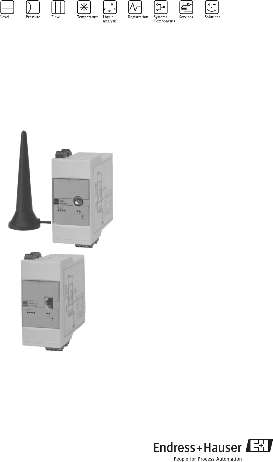
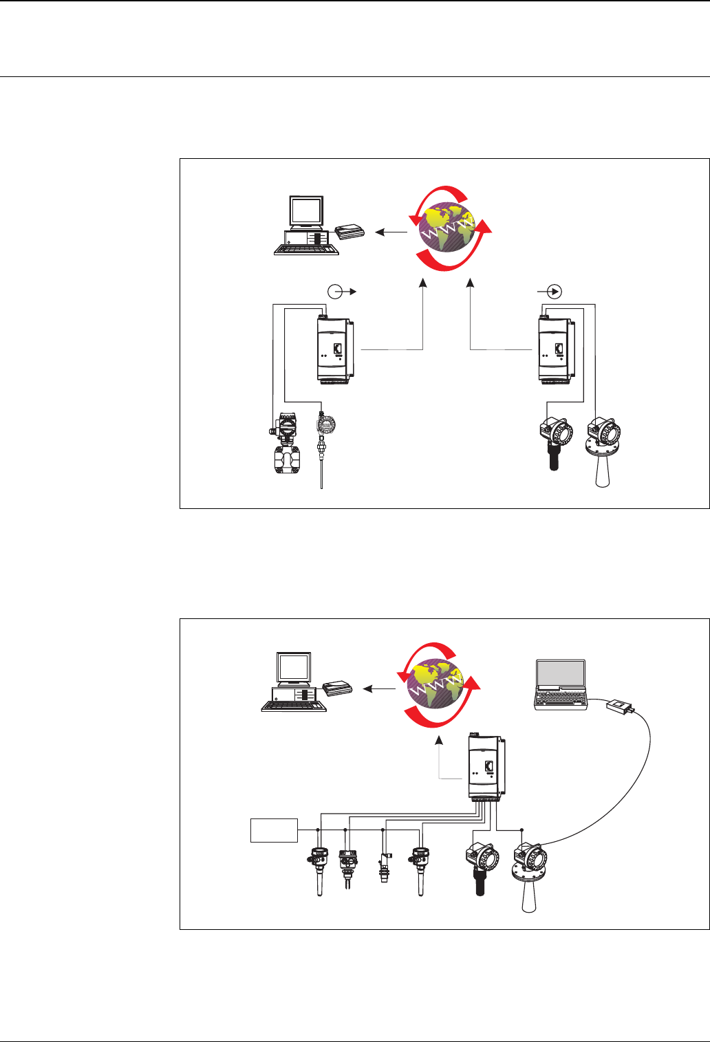
Vendor Managed Inventory By using Fieldgates to interrogate tank or silo levels remotely, suppliers of raw materials can provide their
regular customers with information about the current supplies at any time and, for example, account for them
in their own production planning. For their part, the Fieldgates monitor the configured level limits and, if
required, automatically activate the next supply. The spectrum of options here ranges from a simple purchasing
requisition via e-mail through to fully automatic order administration by coupling XML data into the planning
systems on both sides.
L00-FXA520xx-02-00-06-en-001
Remote maintenance of
measuring equipment
(FXA520 only)
Fieldgates not only transfer the current measured values, they also alert the responsible standby personnel, if
required, via e-mail or SMS. In the event of an alarm or also when performing routine checks, service
technicians can diagnose and configure connected HART devices remotely. All that is required for this is the
corresponding HART operating software (e.g. ToF Tool - FieldTool Package, ReadWin, ...) for the connected
device. Fieldgate passes on the information transparently, so that all options for the respective operating
software are available remotely. Some on-site service operations can be avoided by using remote diagnosis and
remote configuration and all others can at least be better planned and prepared.
L00-FXA520xx-02-00-06-en-002
Fieldgate FXA520
Fieldgate FXA320Fieldgate FXA320
supplier
1...15 sensors 1...15 sensors
customer Bcustomer C
customer A
analogue 4...20 mA
limit
switches
- ToF Tool - FieldTool Package
- ReadWin
- …
Fieldgate FXA520
1...15 sensors 1...15 sensors
Fieldgate FXA320, FXA520
4Endress + Hauser
Communication interface
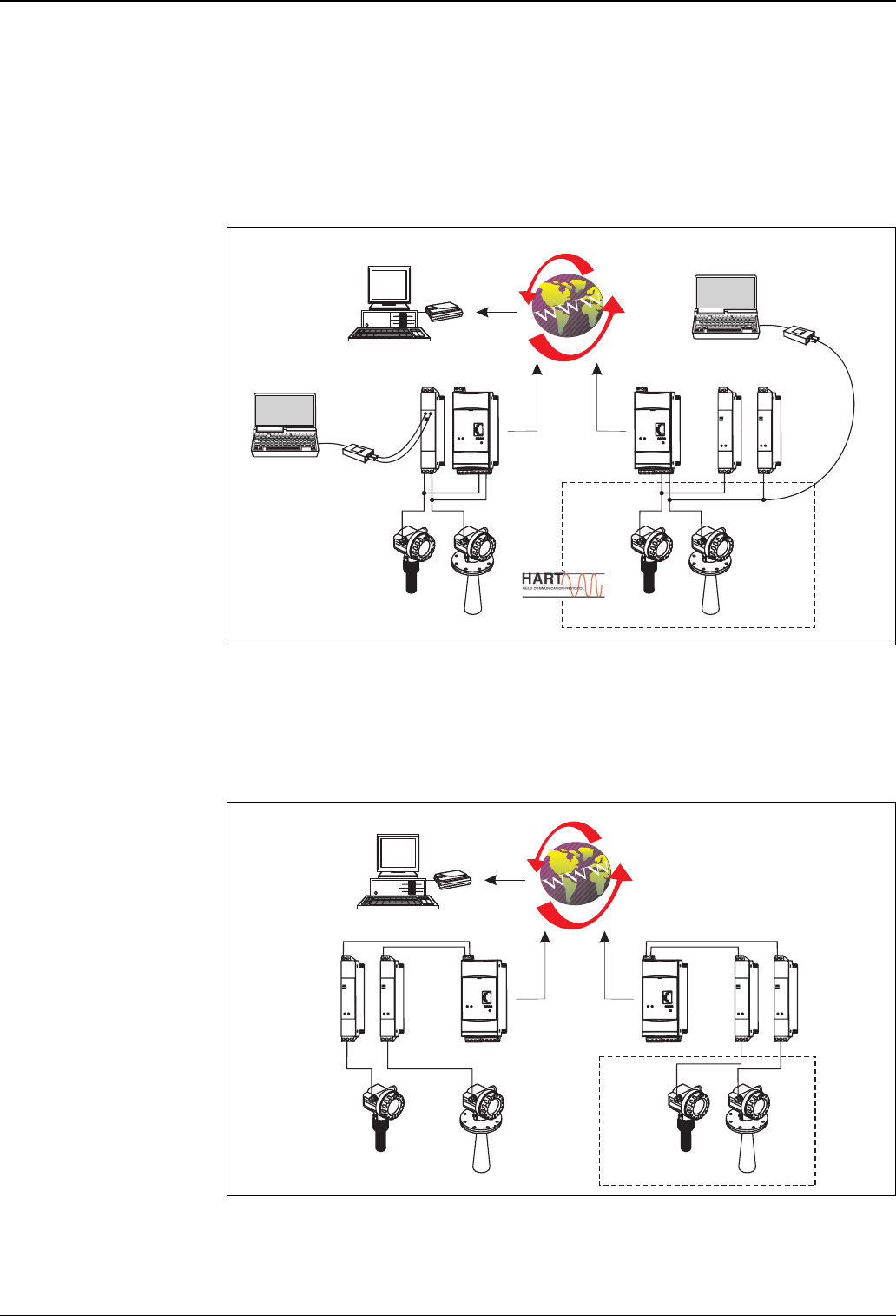
Internet connection If the Fieldgate dials into the Internet permanently via an Internet Service Provider, it is also possible for several
users to access the Fieldgate simultaneously when using an analogue/GSM version. The other advantage is that
the respective user does not require a modem as a receiver at the work place.
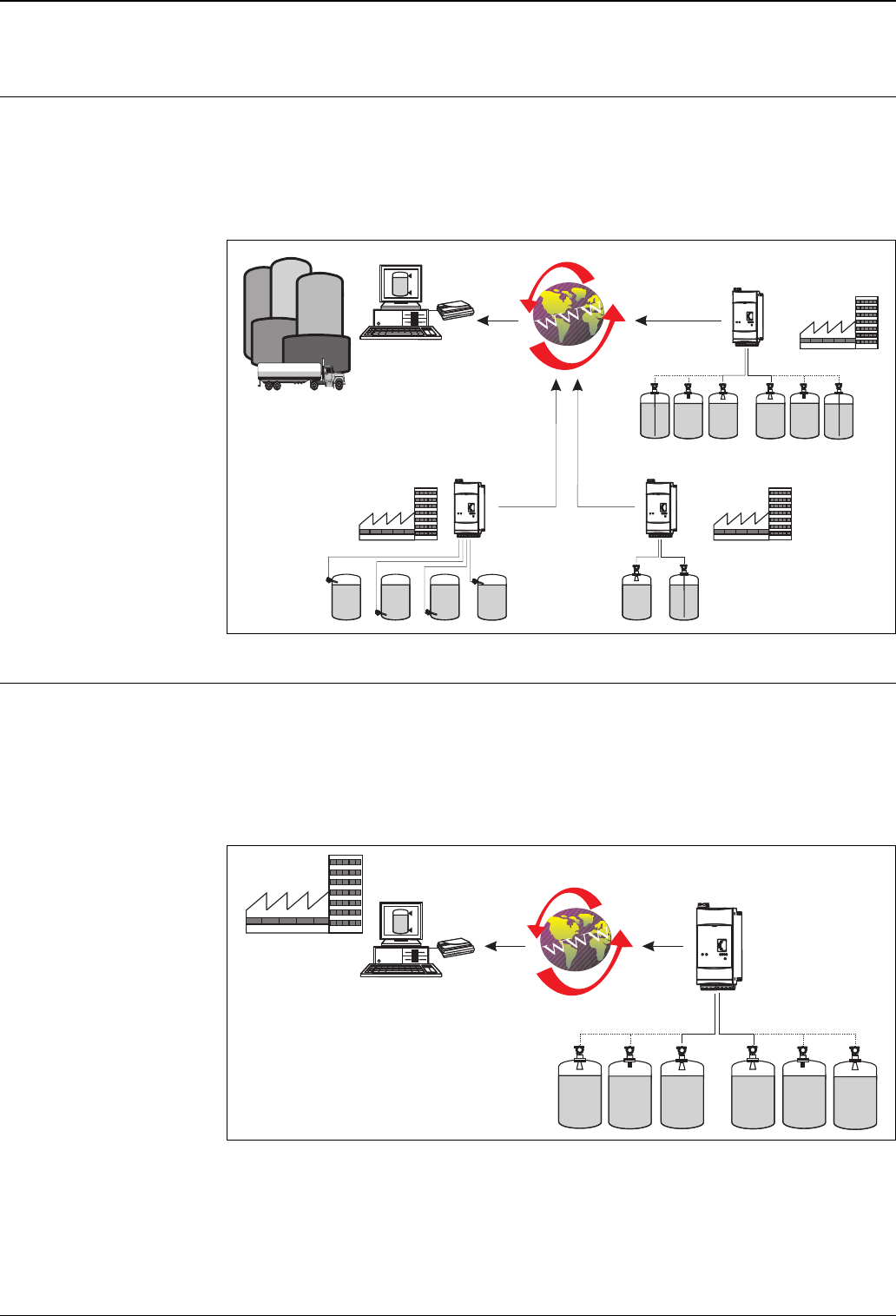
Ethernet The 10 Base T Ethernet interface with RJ45 plug-in connection can be connected to the local network using a
hub or switch. A standard network cable is used for this. In Ethernet operation, you always have access to the
Fieldgate with a standard web browser, since the device is constantly available in the network. Several PCs can
access the Fieldgate simultaneously.
L00-FXA520xx-02-00-06-en-003
Telephone network
(analogue)
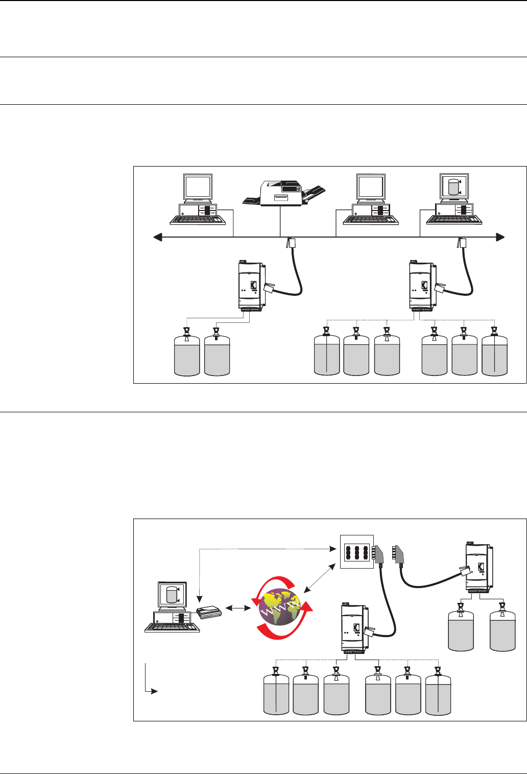
The Fieldgate is connected to the available telephone network via an RJ11 (PSTN) plug connector. This form
of communication is always a point-to-point connection and only one PC can communicate with the device at
any one time. In this configuration, the Fieldgate has to be selected before each access, so that it is ready for
online operation. For example, the Windows internal telecommunications network can be used for dialling.
After this, the Fieldgate can be accessed with a standard web browser (e.g. Internet Provider).
The Fieldgate is also capable of dialling itself into a central server, in order to deliver periodic measured values
for example. Here, it is also possible to transfer the measured values via the Internet using an Internet Service
Provider.
L00-FXA520xx-02-00-06-en-004
RJ 45
RJ 45
Fieldgate FXA520
Fieldgate FXA320
RJ 45
RJ 45
TA E
RJ 11
RJ 11
Fieldgate
FXA520
Fieldgate
FXA320
- data telecomminication connection
Web browser
dial-up:
- …
PSTN (Public Switched Telephone Network)
(e.g.. Telekom)
Fieldgate FXA320, FXA520
Endress + Hauser 5
Mobile communications
network (GSM)
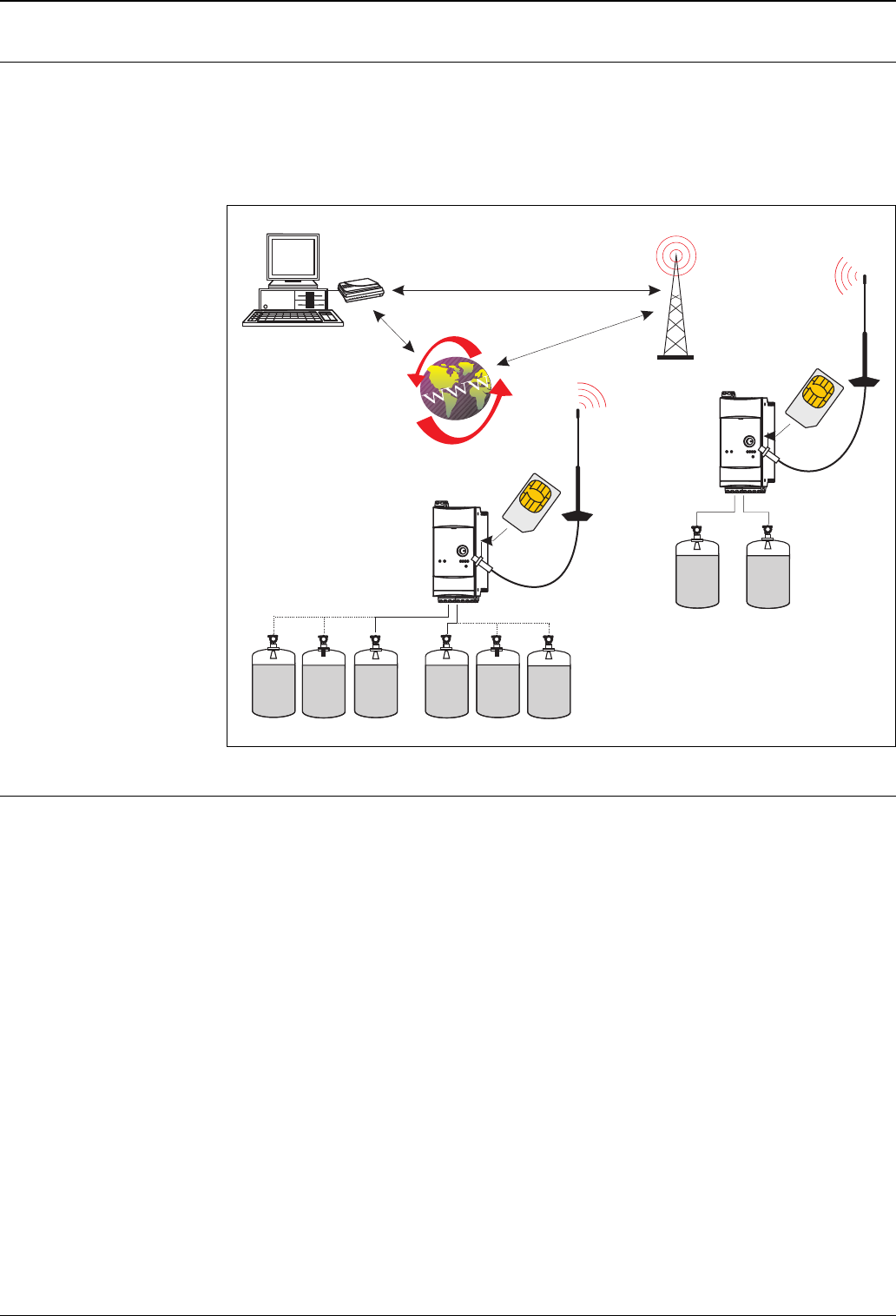
If there is no Ethernet or telephone network available in the Fieldgate's operating location, the data can also be
transferred via GSM using the mobile communications network.
These communications versions can be configured as point-to-point connections or as freely accessible via the
Internet/Intranet. A SIM card from a mobile communications network operator is required for GSM operation.
Communication takes place via the data channel of the SIM card, which may require additional activation,
depending on the GSM provider.
L00-FXA520xx-02-00-06-en-005
GPRS support GPRS (General Packet Radio Services) is a mobile communications technique, which exploits the advantages
of packet-oriented data transmission and channel bundling.
Different from normal GSM connections, no complete channel is reserved for the duration of the connection
between the mobile device and the basis station, rather the data is packed into packets, which can be sent
depending on requirement and capacity. Data transmission in packets enables not only greater transmission
rates but also always-on-operation. The Fieldgate is thus permanently in a position to connect to the Internet,
an Intranet or a mailbox, whereby data is only transferred as required if a new e-mail is sent or a new Internet
page is called up. Here, you are only charged for the amount of data actually transmitted (and not for
connection time).
The GPRS mode of the Fieldgate GSM thus offers the easiest and most cost-effective option for connecting a
measuring point permanently to the Internet or an Intranet. Thanks to always-on-operation, the WAP functions
of the Fieldgate can also be used easily and cost-effectively.
To use the available GPRS functions, the GSM/GPRS provider will need to allocate a public IP address. It will
be necessary to determine in each individual case, whether this additional service is offered by the respective
operator.
Fieldgate FXA520
Fieldgate FXA320
PSTN (Public Switched Telephone Network)
(e.g. Telekom)
SIM
Card
SIM
Card
Fieldgate FXA320, FXA520
6Endress + Hauser
Function and system design
Measuring system Configuration with analogue input 4...20 mA (FXA320 only)
• Two devices can be connected directly.
• Selectable active/passive current input.
L00-FXA320xx-14-00-06-en-001
Configuration with binary input (FXA320 only)
• Four binary inputs with event counter function and frequency measurement.
• Two 4...20 mA current inputs.
L00-FXA320xx-14-00-06-en-002
.
Fieldgate
FXA320
Fieldgate
FXA320
10
0
20
30
40 50
70
80
90
100
!
K
E
E
P
T
I
G
H
T
W
H
E
N
C
I
R
C
U
I
T
A
L
I
V
E
I
N
E
X
P
L
O
S
I
V
E
A
T
M
O
S
P
H
E
R
E
°C
°F %
K
60
Web browser
HTTP script
…
Analogue
Ethernet
GSM
passiveactive
(active)
4...20 mA
4-wire
(passive)
4...20 mA
Loop-
Powered
Commubox FXA191
ToF Tool - FieldTool Package
Fieldgate
FXA320
24 V
DC
Web browser
HTTP script
…
Analogue
Ethernet
GSM
Fieldgate FXA320, FXA520
Endress + Hauser 7
HART - Point-to-Point configuration (FXA520 only)
• Two devices can be connected directly
• Can also be used in hazardous areas
• Qualified for 4...20 mA SIL 2 Loops (IEC 61508)
• Subsequent connection to available installation possible
• A HART communication resistor is already integrated into the device
• Additional connection of 4...20 mA sensors is also possible
L00-FXA520xx-14-00-06-en-007
Configuration with analogue input 4...20 mA (FXA520 only)
• Two devices can be connected directly
• Can also be used in hazardous areas (e.g. RN221N)
• Subsequent connection to available installation possible
L00-FXA520xx-14-00-06-en-006
-
Commubox FXA191
Commubox FXA191
ToF Tool -
FieldTool
Package
ToF Tool - FieldTool Package
.
Fieldgate
FXA520
Fieldgate
FXA520
ENDRESS+HAUSER
RN 221N
ENDRESS+HAUSER
RN 221N
Web browser
HTTP script
ToF Tool - FieldTool
Package
…
Analogue
Ethernet
GSM
e.g. 2 x RN221N-B …
e.g. RNS221
-
.
4...20 mA
4...20 mA
Fieldgate
FXA520
Fieldgate
FXA520
ENDRESS+HAUSER
RN 221N
ENDRESS+HAUSER
RN 221N
ENDRESS+HAUSER
RN 221N
ENDRESS+HAUSER
RN 221N
Web browser
HTTP script
ToF Tool - FieldTool
Package
…
Analogue
Ethernet
GSM
e.g. 2 x RN221N-A …e.g. 2 x RN221N-B …
Fieldgate FXA320, FXA520
8Endress + Hauser
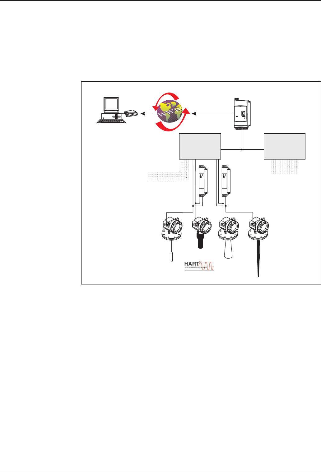
HART Multiplexer configuration (FXA520 only)
• Multiplexer, e.g. KFD2-HMM-16 from Pepperl
• Up to 30 devices (2 x 15) can be connected
• Subsequent connection to available installation possible
• 4...20 mA still possible
Note!
Detailed information on the configuration can be found in the operating instructions BA 268F/00.
L00-FXA520xx-14-00-06-en-005
RS 485
Master Master
RNS221
RS 485
Fieldgate
FXA520
.
maximum 15 devices
Web browser
ToF Tool - FieldTool Package
HTTP script
…
Analog
Ethernet
GSM
HART-Multiplexer
e.g. Pepperl + Fuchs
KFD2-HMM-16
HART-Multiplexer
e.g. Pepperl + Fuchs
KFD2-HMM-16
maximum 15 devices
Fieldgate FXA320, FXA520
Endress + Hauser 9
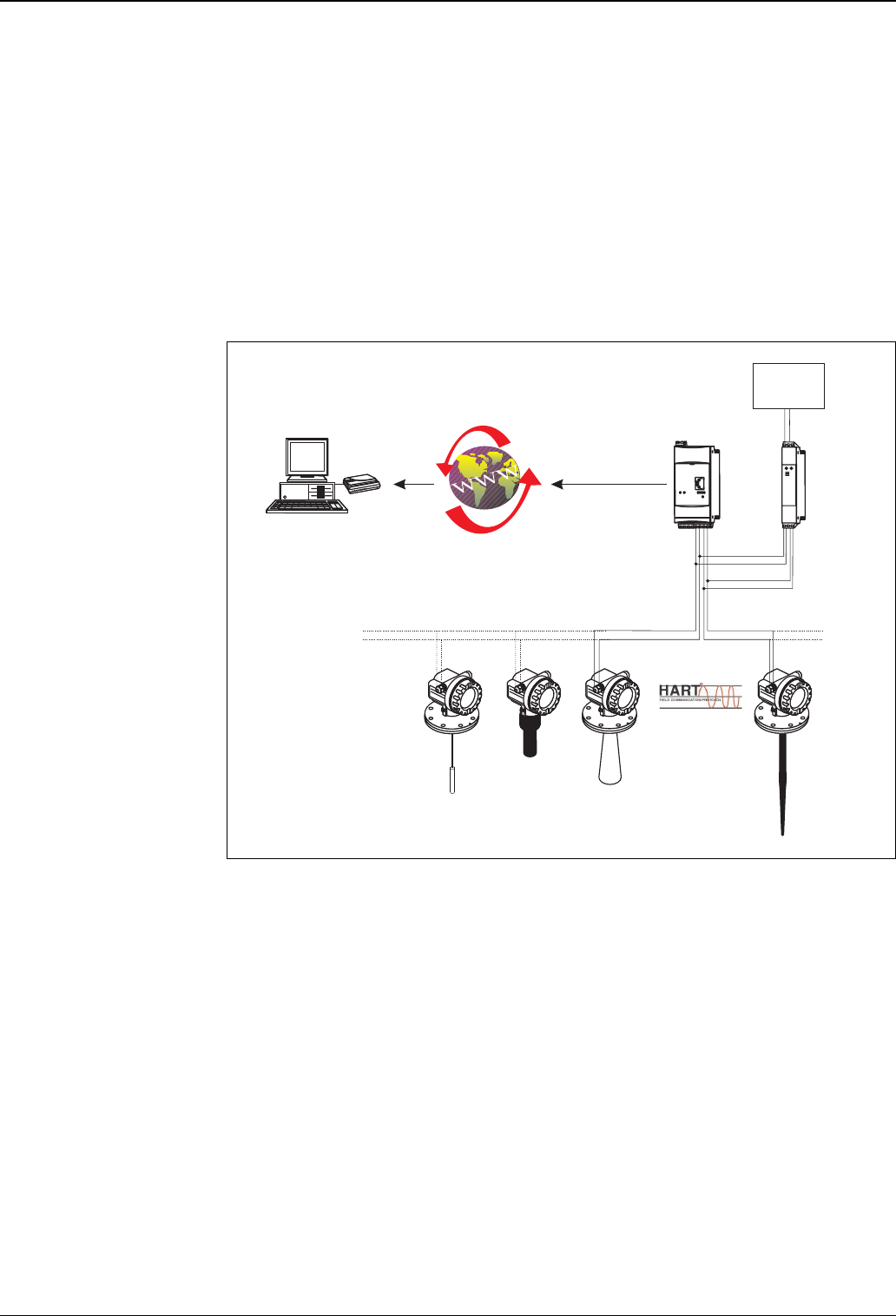
HART - Multidrop configuration (FXA520 only)
• Only HART communication possible
• Up to 30 devices (2 x 15) can be connected
• When the maximum number of devices are connected, observe the following:
– Minimum operating voltage of the connected devices,
– Voltage drop at the communication resistor,
– HART conformity multi-drop of the connected devices,
– Current consumption of the connected devices
– Output characteristics of the power supply unit
– All connected devices must first be allocated their own HART polling address
• A HART communication resistor is already integrated into the device. When the internal communication
resistor is used, the permitted number of devices in multi-drop operation is reduced due to the limited
current-carrying capacity of the resistor.
L00-FXA520xx-14-00-06-en-003
All E+H measuring devices with the HART protocol can, therefore, be used to the full extent with
the Fieldgate
A current list of all E+H measuring devices that have the HART protocol can be found under:
• www.hartcomm.org: "HART Products/Product Catalogue/ ...".
All Endress+Hauser measuring devices with HART protocol can be connected to the Fieldgate.
Even 4...20 mA devices without HART protocol can be operated in conjunction with the Fieldgate, e.g. limit
switch (Liquiphant, ...). However, then only the measured value can be read. The remote maintenance
function is not given for 4...20 mA devices because the HART protocol is required for this function.
Multidrop
Connector
FXN520
Fieldgate
FXA520
supply
voltage
24 V
Web browser
ToF Tool - FieldTool Package
HTTP script
…
Analogue
Ethernet
GSM
up to 15 devicesup to 15 devices
device address: 15 … … 03 02 01
channel 1 channel 2
Fieldgate FXA320, FXA520
10 Endress + Hauser
Input
Analogue 4...20 mA inputs FXA520
2 channels: joint ground of both channels, no galvanic isolation.
FXA320
2 channels with galvanic isolation. Can be used independently as active or passive input.
RS-485 interface
(FXA 520 only)
Channel 1&2 - passive
Max. input voltage per channel 35 V
Max. input current per channel 45 mA
Input impedance approx. 100 Ω
Accuracy ≤ 1 %
Voltage drop (incl. diode against reverse polarity) ≤ 3 V
Connection cable Instrument cable, unscreened
Cable resistance max. 25 Ω per core
Channel 1&2 - active
Output voltage 15 V ±5% / (22 mA)
No-load voltage 23.5 V ±5%
Output current max. 23 mA
Short-circuit current max. 64 mA
short-circuit duration Unlimited
Connection cable Instrument cable, unscreened
Cable resistance max. 25 Ω per core
Channel 1&2 - passive
Max. input voltage per channel 35 V
Max. input current per channel 45 mA
Input impedance 254 Ω
Accuracy ≤ 0.5 %
Voltage drop (incl. diode against reverse polarity) ≤ 6.4 V
Connection cable Instrument cable, unscreened
Cable resistance max. 25 Ω per core
Galvanic isolation 500 V RMS
Termination resistor A-B 120 Ω fully integrated
Fieldgate FXA320, FXA520
Endress + Hauser 11
HART channel 1&2
(FXA 520 only)
The HART signal is capacitive coupled and decoupled via a communication resistor
Galvanic isolation between HART channel 1 and channel 2
Ex-isolation between field devices and internal circuits.
Binary inputs (FXA 320 only) Galvanic isolation of all channels from the rest of the current circuits. Each 2 channels have the same reference
potential.
Output
Output signal • A relay for alarm in the event of a fault
• Switching-off the sensor's power supply (in the event of a fault, power-save mode)
• Switching capacity of relay contacts:
U~ maximum 253 V
I~ maximum 2 A
P~ maximum 500 VA at cos ϕ 0.7
U- maximum 40 V
I- maximum 2 A
P- maximum 80 W
Overvoltage category as per
EN 61010
II
Protection class II (double or reinforced insulation)
Communication resistor in the 4...20 mA signal line Integrated 270 Ω communication resistor, for optional
use, max. 45 mA!
Short-circuit duration (without interrior communication
resistor)
Unlimited
Output voltage U0 in the event of a fault (Ex) Max. 6.5 V
Max. current for EEx ia (Ex) 5.97 mA
Max. power output (Ex) 39 mW
Maximum input voltage (Ex) 30 V
Maximum input voltage (non-Ex) 45 V
Number of digital inputs 4
Input signal voltage L-signal: -3 ... +5 V
H-signal: +15 ... +30 V
Input current with H-signal 5 mA
Max. quiescent current with L-signal 1 mA
Measuring range of event counter function 0 ...12.5 kHz
Measuring range of frequency measurement 4.7 Hz (±1%) ... 12.5 kHz (±4%)

Fieldgate FXA320, FXA520
12 Endress + Hauser
Power supply
Electrical connection Terminal blocks
The removable terminal blocks are isolated after intrinsically safe connections (on top of device) and non-
intrinsically safe connections (on bottom of device). Furthermore, the terminal blocks are also different in
colour. Blue for the intrinsically safe area and grey for the non-intrinsically safe area. These distinctions allow
for safe cable routing.
Connecting the devices
(To the upper, blue terminal blocks).
The two-core connecting wire between the Fieldgate FXA520 and HART devices can be a usual commercial
instrument cable or cores in a multi-core cable for measuring purposes. If strong electromagnetic interferences
have to be expected, e.g. from machines or radios, using a screened cable is recommended. Only connect the
screening to the
grounding connection in the device.
The HART signal is decoupled passively without power supply.
Operating the device in hazardous areas (FXA520 only)
The national explosion protection directives for designing and routing the intrinsically safe signal cable must be
observed. Maximum permitted values for capacity and inductivity can be found in the Safety Instructions of
XA 188F.
Connecting the supply voltage
(Terminal 1 and 2)
For the voltage versions, see the Ordering information on page 23. A fuse is built into the power supply circuit
so that a fine-wire fuse does not need to be connected in series.
The Fieldgate is equipped with reverse polarity protection.
Supply voltage Alternating current version (AC):
Voltage range: 85...253 V, 50/60 Hz
Safe galvanic isolation between mains power supply and internal circuits
Direct current version (DC):
Voltage range: 20...60 VDC or 20 ... 30 VAC
Reverse polarity protection guaranteed by bridge rectifier
Safe galvanic isolation between mains power supply and internal circuits
Power consumption
FXA520 AC (at 253 VAC) DC (at 20 VDC)
Analogue 6 VA 2 W
Ethernet 4.9 VA 1.5 W
GSM
Send mode 8 VA 4 W
Standby 4.5 VA 1 W
FXA320 AC (at 253 VAC) DC (at 20 VDC) Solar (at 10 VDC)
Analogue 8 VA 3.5 W —
Ethernet 8 VA 3.5 W —
GSM
Send mode 8 VA 4.8 W 4.6 W
Standby 6 VA 2.9 W 2.8 W
Fieldgate FXA320, FXA520
Endress + Hauser 13
Operating conditions: Installation
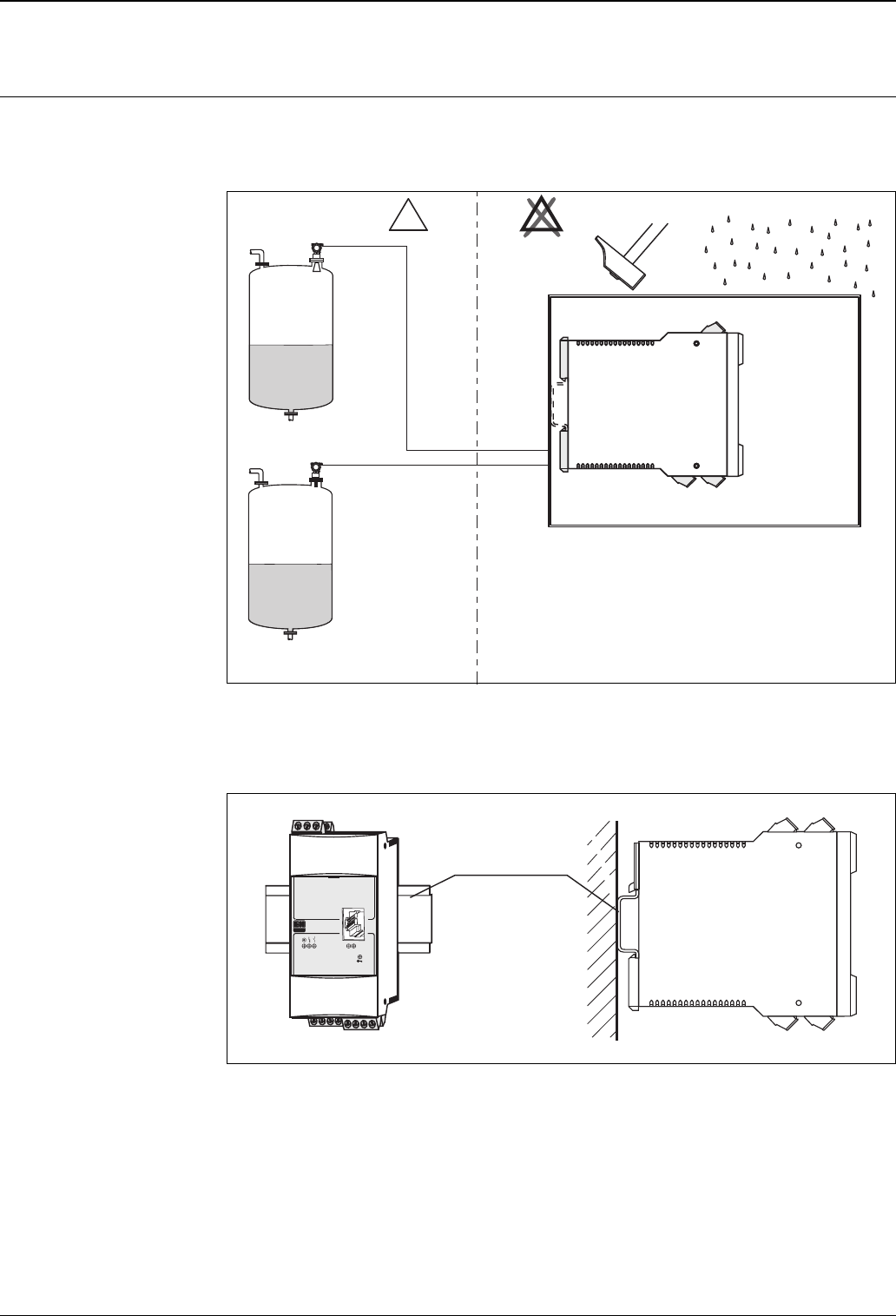
Installation instructions Mounting location
The Fieldgate must be placed in a cabinet, away from hazardous areas. There is also a protective housing (IP65)
for two devices available for outdoor installation.
L00-FXA520xx-17-00-06-de-002
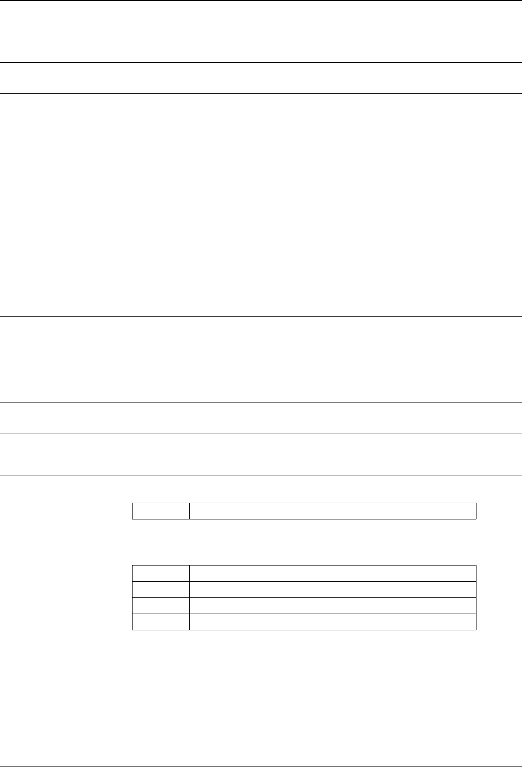
Orientation
Vertical on DIN top-hat rail (HT 35 as per EN 60715).
L00-FXA520xx-17-00-06-de-001
min. IP 65
E
X
E
X
EN 60715; HT 35 x 7.5
EN 60715; HT 35 x 15
ANALOG
FXA 520
L
D
Fieldgate FXA320, FXA520
14 Endress + Hauser
Operating conditions: Environment
Mounting location Cabinet or protective housing
Permitted ambient
temperatures
For individual mounting
-20 C... +60 C
For series mounting without lateral spacing
-20 C... +50 C
Storage temperature
-25 C... +85 C (preferably at +20 C)
Installation in protective housing
-20 C... +40 C
Maximum two Fieldgates can be installed into a protective housing.
Caution!
The devices must be mounted such that they are protected from the weather and from impacts, and where
possible in places that are not exposed to direct sunlight. This must be especially observed in regions with warm
climates.
Climatic and
mechanic
application class
3K3
In accordance with DIN EN 60721-3-3
3M2
In accordance with DIN EN 60721-3-3
Ingress protection IP 20, in accordance with EN 60529
Electromagnetic
compatibility (EMC)
Interference Emission to EN 61326, Electrical Equipment Class B.
Application in protection
functions
The FXA 520 can be attached back effect freely to protection functions that are classified in SIL 2 to IEC 61508.
SFF1
1) SFF = Safe Failure Fraction
60%
TI1
1) TI = Test Interval between life testing of the protection function (in years)
PFDavg2
2) PFDavg = Probability (average) of a dangerous Failure on Demand
1 year 1,23 x 10⁻⁶
5 years 6,13 x 10⁻⁶
10 years 1,23 x 10⁻⁵
Fieldgate FXA320, FXA520
Endress + Hauser 15
Mechanical construction
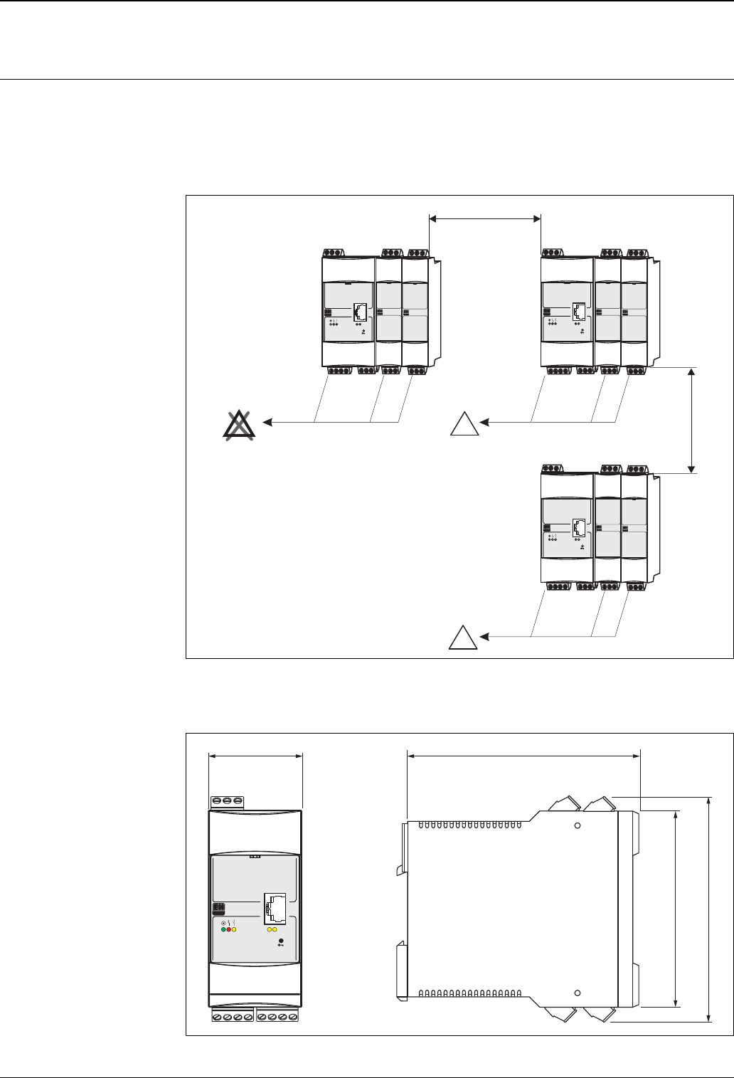
Design, dimensions Note!
100 mm = 3.94 in
• Housing: aligned housing (top-hat rail design) made of plastic
• Installation: on top-hat rail as per EN 60715; HT 35x7.5 or EN 60715; HT 35x15
• Ingress protection as per EN 60529; IP 20
L00-FXA520xx-06-00-06-yy-002
Dimensions
L00-FXA520xx-06-00-00-de-001
Min. 50 mm
Min. 50 mm
E
X
E
X
E
X
ANALOG
FXA 520
L
D
ANALOG
FXA 520
L
D
ANALOG
FXA 520
L
D
45 mm
95 mm
112 mm
108 mm
ANALOG
FXA 520
L
D
Fieldgate FXA320, FXA520
16 Endress + Hauser
Weight approx. 250 g
Materials Housing
Polycarbonate
Colour: light grey, RAL 7035
Front cover
Polyamide PA6
Colour: blue
Fixing slide (for fastening on the top-hat rail)
Polyamide PA6
Colour: black, RAL 9005
Terminals Connection cross-section
maximum 1 x 2.5 mm or 2 x 1.5 mm
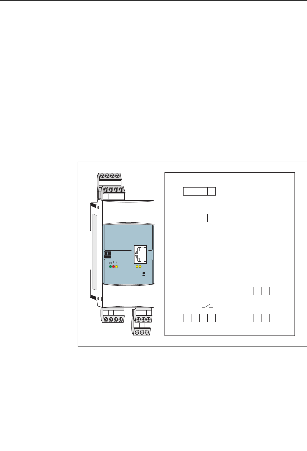
Terminal assignment Fieldgate FXA320
L00-FXA520xx-04-00-06-en-012
supply relay
sensor 1
sensor 2
binary inputs
passive aktive
passive aktive
1
2
15
16
26
27
28
11
12
13
14
7
8
9
10
22
23
24
ANALOG
FXA 320
L
D
78910
11 12 13 14
28
26
27
15 16
N
12
L1
L+ L-
23 24
22
BI1
BI3
BI2
BI4
GND1
GND2
-
-
-
-
+
+
+
+
Fieldgate FXA320, FXA520
Endress + Hauser 17
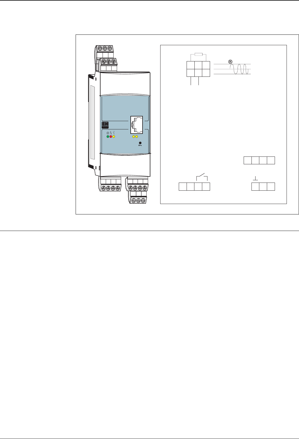
Terminal assignment Fieldgate FXA520
L00-FXA520xx-04-00-06-en-001
Plug-in connections Connection socket for Ethernet Fieldgate versions:
RJ45 socket
Connection socket for GSM antenna:
FME socket (male)
Connection plug for DAT module:
8-pin plug connector in 2.54 mm raster, 2 rows
Connection plug for PC cable:
3-pin plug connector in 2.54 mm raster, 1 row
HART channel 2 (EEx ia)
and
HART channel 1 (EEx ia)
supply relay
analogue input 4...20 mA
270 / 0.55 W (communication resistor)Ω
1
2
15
16
26
27
28
11
12
13
7
8
9
21
22
23
24
ANALOG
FXA 520
L
D
789
11 12 13
CH 1
CH 2
28
26
27
15 16
N
12
L1
L+ L-
23 24
21 22
--++
CH1 CH2
AB
RS-485
4..20 mA
HART
Fieldgate FXA320, FXA520
18 Endress + Hauser
Human interface
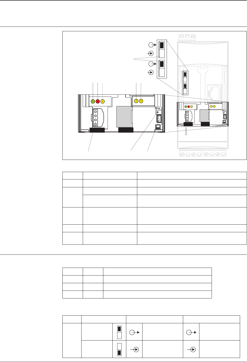
Display elements
L00-FXA320xx-07-00-06-xx-005
Operating elements For the arrangement of the elements, see the diagram above.
FXA320 only
Position Light emitting diode (LED) Meaning
1 Green LED constant Displays the correct power supply
2 Red LED constant Displays a fault
Red LED flashes Displays a warning / On site communication via PC / Hardware is
unlocked / system start
3 Yellow LED Switching status of the built-in relay / LED on = relay tightens
– LED off = relay de-energised
– LED on = relay energised
4 Yellow LED Displays a successful connection
5 Yellow LED Displays a transfer activity / GSM version: field strength display if no
connection
678
12 3
CH 1
CH 2
45
9
Position Element Meaning
6 Socket Connection socket for DAT module
7 Button Button for hardware security locking and configuration reset
8 Socket Connection socket for PC cable (service connector)
Position Element Current input channel 1 (CH1) Current input channel 2 (CH2)
9 Switch position
(up) aktive aktive
Switch position
(down) passive passive
Fieldgate FXA320, FXA520
Endress + Hauser 19
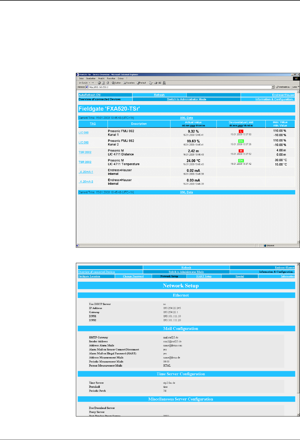
Operation concept Fieldgate offers world-wide remote monitoring, remote diagnosis and remote configuration of Smart
transmitters with the international used HART® protocol. Measured values become available world-wide via
Internet and can be efficiently processed. A standard web browser is used for visualising and remote inquiry.
Fieldgate displays parameters and measured values of field instruments on an HTML page. Max. 30 measured
values can be displayed. Up to 4 measured values can be displayed per device.
Fieldgate FXA520
L00-FXAY2Kxx-20-13-00-en-301
L00-FXA520xx-20-13-00-en-167
Fieldgate FXA320, FXA520
20 Endress + Hauser
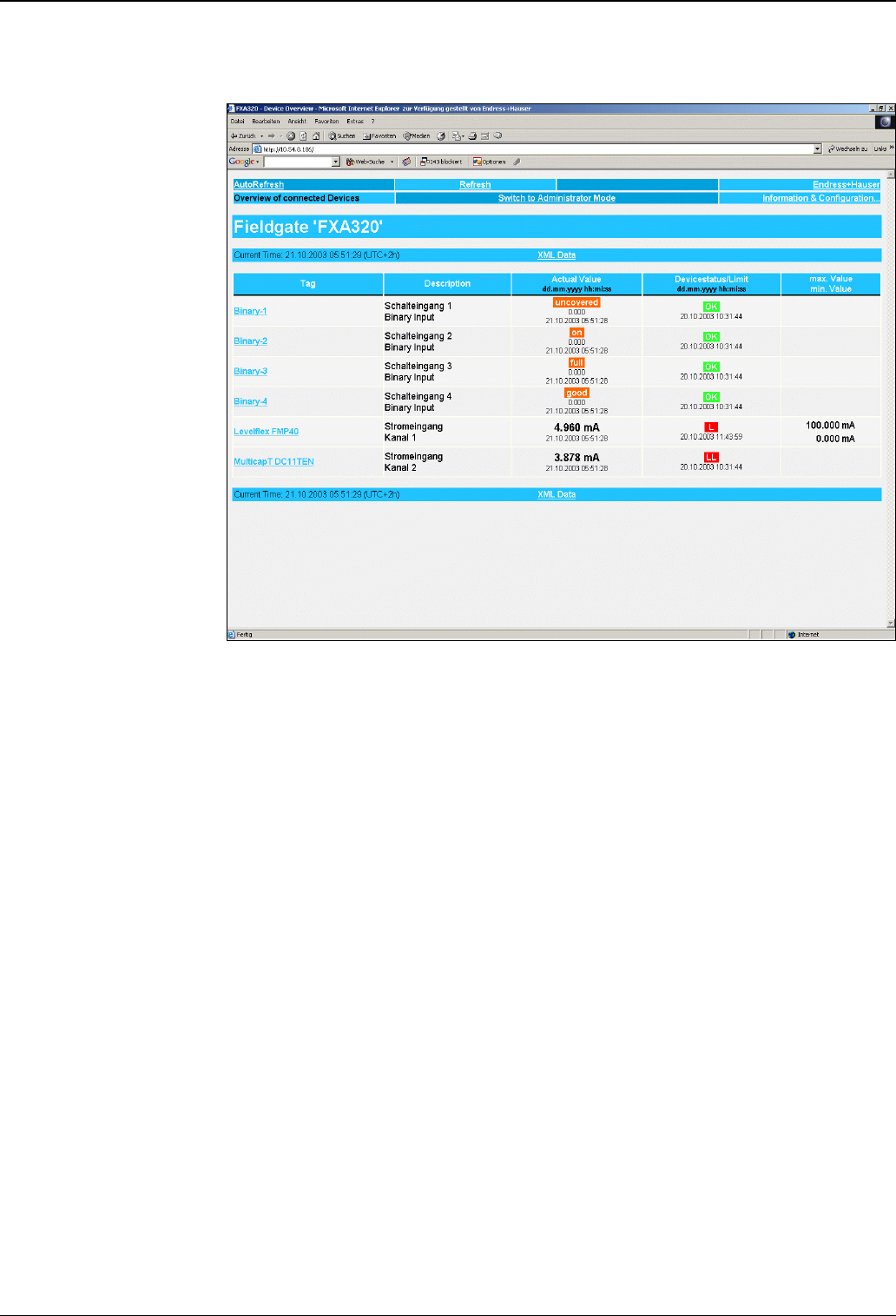
Fieldgate FXA320
L00-FXA320xx-20-13-00-en-001
Fieldgate FXA320, FXA520
Endress + Hauser 21
Certificates and approvals
CE mark The Fieldgate meets the legal requirements of the EC directives.
Endress+Hauser confirms that the device has been successfully tested by applying the CE label.
Ex-approval FXA520
see Ordering information
Explosion protection FXA520
[EEx ia] IIC
Intrinsically safe circuits
Values for each circuit:
Max. external values in accordance with the following table:
If inductances and capacitances are concentrated the following values apply:
Other standards
and guidelines
Other standards and guidelines that have been observed when designing and developing the Fieldgate.
EN 60529
Ingress protections for housing (IP code)
EN 61010
Safety requirements for electrical equipment for measurement, control and laboratory use
EN 61326
Interference emission (class B operating equipment), interference immunity (appendix A - industrial sector)
EN 60950 (IEC 950)
Safety of information technology equipment
Voltage Uo= 6.5 VDC
Current Io= 6 mA
Power Po= 9.8 mW
Group Capacitance Co [µF] Inductance Lo [mH]
IIC 25 1000
IIB 570 1000
Group Capacitance Co [µF] Inductance Lo [mH]
IIC
2
2
1.5
0.5
1
5
IIB
10
10
7
1
2
5

Fieldgate FXA320, FXA520
22 Endress + Hauser
Telecommunications Regulatory Compliance
Fieldgate analogue version North America
FCC CFR 47, part 15 and part 68
Europe
Telecoms Terminal Equipment Directive (98/13/EG)
European approval TBR 21
Fieldgate GSM version North America
FCC CFR 47 Part 15 and Part 24
Federal Communications Commission Notice
This device generates, uses, and can radiate radio frequency energy and, if not installed and used in accordance
with the instructions, may cause harmful interference to radio communications. However, there is no
guarantee that interference will not occur in a particular installation. If this equipment does cause harmful
interference to radio or television reception, which can be determined by turning the device off and on, the
user is encouraged to try to correct the interference by one or more of the following measures:
– Reorient or relocate the receiving antenna.
– Increase the separation between the equipment and receiver.
– Connect the equipment into an outlet on a circuit different from that to which the receiver is connected.
To ensure that the unit complies with current FCC regulations and safety requirements limiting both maximum
RF output power and human exposure to radio frequency radiation, use an antennna with a maximum gain of
2dBi and a separation distance of at least 20 cm must be maintained between the unit's antenna and the body
of the user and any nearby persons at all times and in all applications and uses.
Modifications
The FCC requires the user to be notified that any changes or modifications made to this device that are not
expressly approved by Endress+Hauser may void the user's authority to operate the equipment.
Federal Communications Commission Statement
FCC-ID: LCG-FG-FXA52x-32x
This device complies with Part 15 of the FCC rules. Operation is subject to the following two conditions:
(1) This device may not cause harmful interference, and
(2) This device must accept any interference received, including interference that may cause undesired
operation.
Wireless Notices
In some situations or environments, the use of wireless devices may be restricted. Such restrictions may apply
aboard airplanes, in vehicles, in hospitals, near explosives, in hazardous locations, etc. If you are uncertain of
the policy that applies to the use of this device, please ask for authorization to use it prior to turning it on.
Fieldgate FXA320, FXA520
Endress + Hauser 23
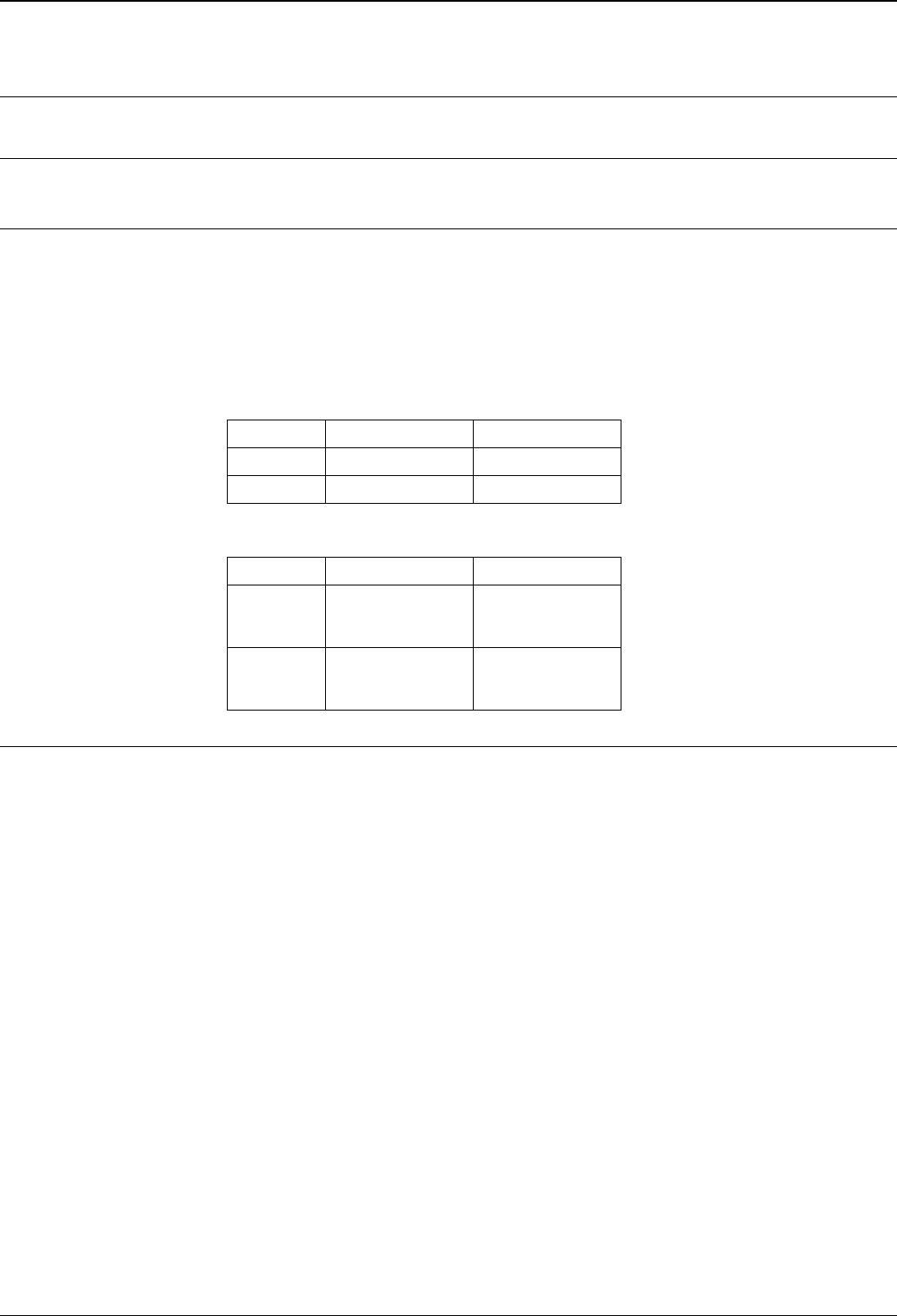
Ordering information
Fieldgate FXA320
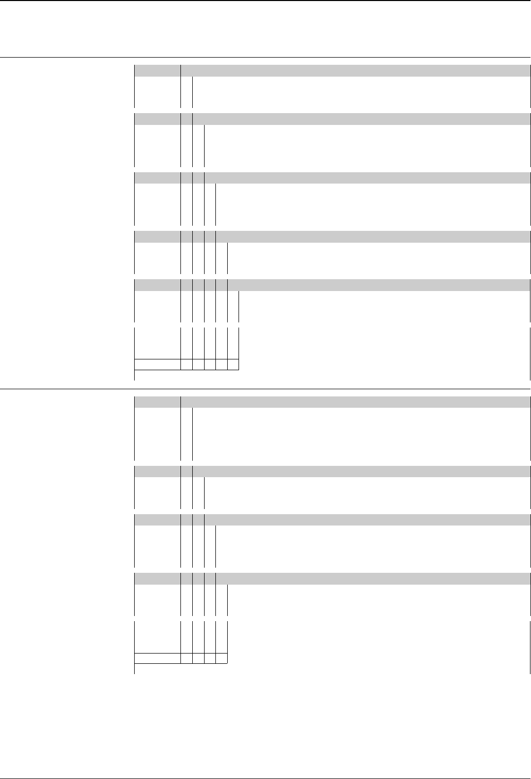
Fieldgate FXA520
Note!
A PC cable is included in the scope of supply with FXA320/520.
10 Certificates
A Version for non-hazardous areas
F CSA, general purpose
Y Special version
20 Power supply
A Power supply 85...253 VAC, 50/60 Hz
E Power supply 20...60 VDC, 20...30 VAC
G Solar panel connection 10...20 VDC
Y Special version
30 Modem interface
1 Ethernet - 10 Base T
2 Analogue modem
4 GSM modem without antenna
9 Special version
40 DAT module
A without DAT module
B with DAT module
YSpecial version
50 Input
A 2-channel analogue (4...20 mA)
B 2-channel analogue (4...20 mA) + 4 binary
FXA320- Complete product designation
10 Certificates
A Version for non-hazardous areas
G ATEX II (1) GD EEx ia IIC T6
P FM IS - Class I, II, III, Division 1, Group A-G
S CSA IS - Class I, II, III, Division 1, Group A-G
Y Special version
20 Power supply
E Power supply 20...60 V DC, 20...30 V AC
A Power supply 85...253 V AC, 50/60 Hz
Y Special version
30 Modem interface
1 Ethernet - 10 Base T
2 Analogue modem
4 GSM modem without antenna
9 Special version
40 DAT module
A without DAT module
B with DAT module
YSpecial version
FXA520- Complete product designation

Fieldgate FXA320, FXA520
24 Endress + Hauser
Accessories
Note!
The following table gives an overview of possible application for the individual accessory parts with the
Fieldgate FXA320 or FXA520.
Protective housing The protective housing in protection class IP 66 is equipped with an integrated top-hat rail and is closed with
a transparent cover that can also be lead sealed.
Dimensions:
W 180 / H 182 / D 165
Colour:
Light grey RAL 7035.
Order number: 52010132.
DAT module An external EEPROM, in which the configuration data is saved identically to the internal EEPROM, can be
attached optionally via plug. For example, this allows for the FXA320/520 to be changed in the event of a
defect, without losing the customer-specific configuration data.
Order number: 52013311.
PC cable A PC can be connected to the FXA320/520 for configuration purposes via a serial RS 232 connection. Order
number: 52013984.
Telephone cable RJ11 (analogue plug, double-sided, length: 5 m). Order number: 52014031.
Fieldgate data access Fieldgate Data Access software assists with the collection of data from different Fieldgates. The fetching of data
is controlled via entries in the Scheduler. Time control can be via periodic intervals or at user-defined times.
Under Windows NT4 / 2000 / XP, collection of the data can accomplished via a "system service", which runs
in the background. The data are saved in CSV format. Further processing of the data can be carried out with,
e.g. Excel.
Fieldgate OPC server The Fieldgate OPC server provides an interface between one or more Endress+Hauser Fieldgate devices and
all possible OPC Data Access 2.0 compatible Clients. The Fieldgate can be connected via a dial-up modem or
through a TCP/IP network.
Java applets Java applets for a customised view of the screen.
Accessory Fieldgate FXA320 Fieldgate FXA520
Protective housing X X
DAT module X X
PC cable X X
Telephone cable (analogue version only) is required is required
Fieldgate data access X X
Fieldgate OPC server X X
Java applets X X
Antenna (GSM version only) is required is required
HART Client (FXA 520 only) — X
Multiplexer (FXA 520 only) — X
E+H power supply units (FXA 520 only) — X

Fieldgate FXA320, FXA520
Endress + Hauser 25
Antenna Antenna for communication via mobile communications (GSM):
• Triband flat antenna.
Order number: 52018396.
• Dual band station antenna.
Order number: 52018395.
HART Client (FXA 520 only) The HART Client is a free add-on which is required for remote configuration via HARTtools (e.g. with
ToF Tool - FieldTool Package, ReadWin, ...). You can download the current software version from the Internet
from the Endress+Hauser product pages (download: http://www.endress.com).
Multiplexer (FXA 520 only) Accessories for HART Multiplexer system (from Pepperl+Fuchs):
• HART Multiplexer Master KFD2-HMM-16.
Order number: 52017691.
• Master-interface connecting cable.
Order number: 52017687.
• HART Multiplexer slave KFD0-HMS-16.
Order number: 52020232.
• Master-slave connecting cable.
Order number: 52020233.
• Interface module without communication resistor.
Order number: 52017689.
• Interface module with communication resistor.
Order number: 52017690.
• Switched-mode power supply.
Order number: 52017688.
E+H power supply units
(FXA 520 only)
RMA422
Multifunctional 1-2-channel top-hat rail device with intrinsically safe current inputs and transmitter power
supply, limit value monitoring, mathematics functions and 1-2 analogue outputs.
RNS221
Power supply unit for supplying power to two two-wire sensors or transmitters in non-hazardous areas.
RN221N
Isolator with power supply for safely isolating 4...20 mA standard signal circuits.
RMA421
Multifunctional 1-channel top-hat rail device with universal input, transmitter power supply, limit value
monitoring and analogue output.
E+H Multidrop Connector
FXN520
Operated several devices in multi-drop operation for FXA520. Order number: 52023652.
Solarbox Self-sufficient current supply unit for FXA320 with solar panel.

Fieldgate FXA320, FXA520
26 Endress + Hauser
Documentation
Operating Instructions KA 193F/00/a6
Mounting and installation instructions for Fieldgate FXA520. Order number: 52013633.
KA 215F/00/a6
Mounting and installation instructions for Fieldgate FXA320. Order number: 52020867.
BA 258F/00/en
Operating Instructions for Fieldgate FXA520 (online help in the Internet browser).
BA 282F/00/en
Operating Instructions for Fieldgate FXA320 (online help in the Internet browser).
BA 273F/00/en
Operating instructions for Fieldgate Data Access software (download via the Internet).
Ba 272F/00/en
Operating instructions for Fieldgate OPC server software (download via the Internet).
Certificates XA 188F-A/00/a3
Safety Instructions for electrical operating equipment for hazardous areas.
Order number: 52013636.
ZD 086F/00/en
Control Drawings (FM). Order number: 52013634.
ZD 087F/00/en
Control Drawings (CSA). Order number: 52013635.
Accessories BA 265F/00/de
Cable for the HART Multiplexer-System. Order number: 52017693.
BA 266F/00/en
Interface Modul without Communication resistor. Order number: 52017694.
BA 267F/00/de
Interface Modul with Communication resistor. Order number: 52017695.
BA 268F/00/en
HART-Multiplexer Master KFD2-HMM-16. Order number: 52017696.
BA 283F/00/en
HART Multiplexer slave KFD0-HMS-16. Order number: 52021044.
BA 269F/00/en
Switched power supply. Order number: 52017698.
TI 391F/00/en
Solarbox for Fieldgate FXA320. Order number: 52023595.

Fieldgate FXA320, FXA520
Endress + Hauser 27

Fieldgate FXA320, FXA520
International Head Quarter
Endress+Hauser
GmbH+Co. KG
Instruments International
Colmarer Str. 6
79576 Weil am Rhein
Deutschland
Tel. +49 76 21 9 75 02
Fax +49 76 21 9 75 34 5
www.endress.com
info@ii.endress.com
TI369F/00/en/04.04
FM+SGML 6.0 ProMoDo