EnergyICT NV EPIO-RF EPIO-RF User Manual EMNL000015 05 EN EpIO
EnergyICT NV EPIO-RF EMNL000015 05 EN EpIO
UserManual.wiki
>
EnergyICT NV
>
EPIO RF User Manual
Users manual
Navigation menu
Upload a User Manual
Namespaces
Wiki Guide
HTML
PDF
Info
Views
User Manual
Discussion / Help
Navigation
![5/20 Chapter 1: Introduction Overview Introduction This chapter provides the user with an introduction to the EpIO, its main internal components and its main functions. Chapter description This chapter describes the following topics: Topic Page About the EpIO [6] Components [8]](https://usermanual.wiki/EnergyICT-NV/EPIO-RF/User-Guide-898092-Page-7.png)
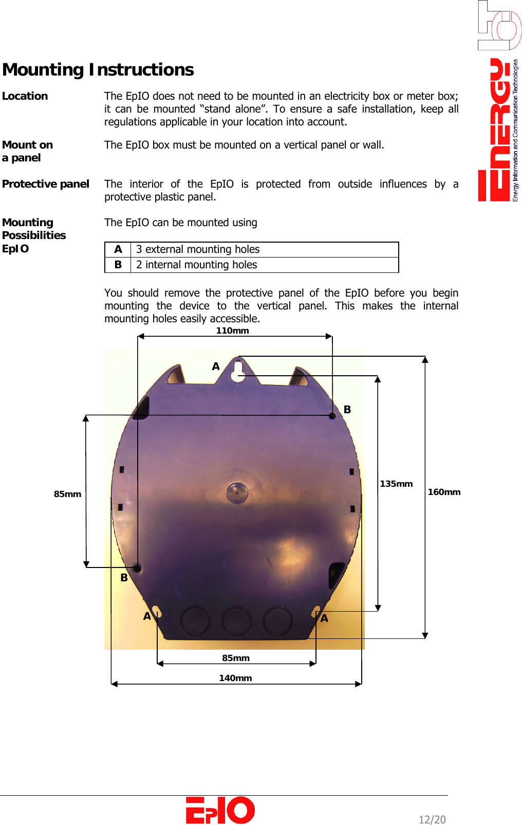
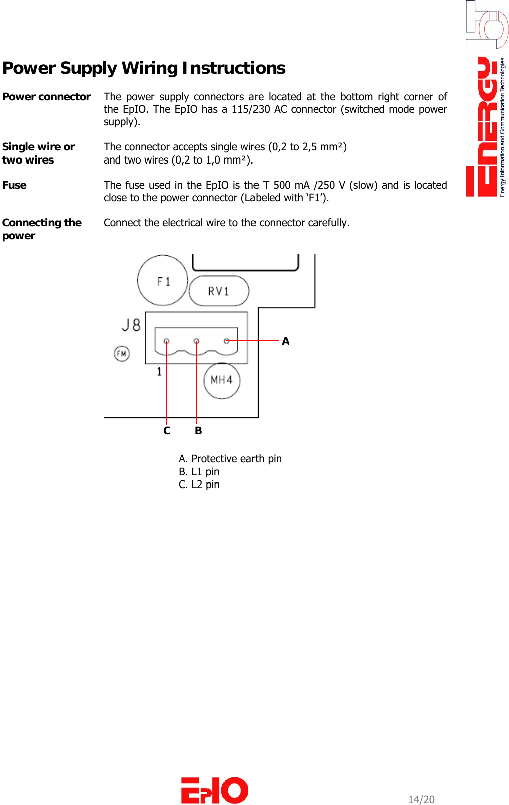
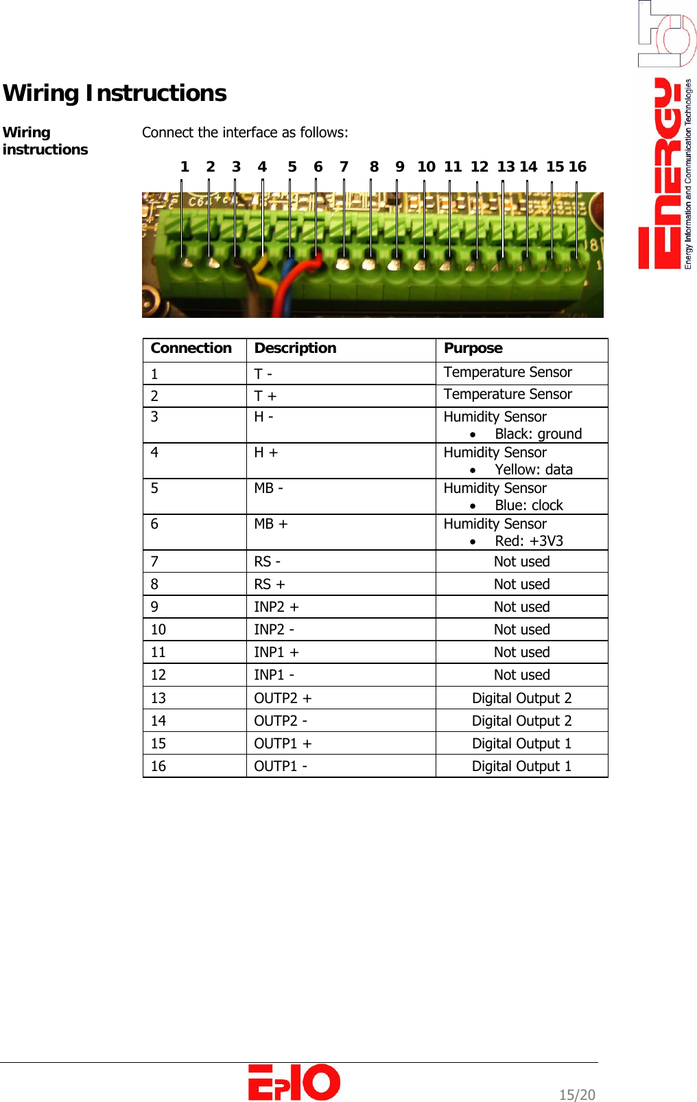
![11/20 Chapter 2: Mounting and Wiring Overview Introduction This chapter provides information on the physical installation of the EpIO device, including mounting and wiring instructions. Chapter description This chapter describes the following topics: Topic Page Mounting Instructions [12] Power Supply Wiring Instructions [14] Wiring Instructions [15] Protective Panel](https://usermanual.wiki/EnergyICT-NV/EPIO-RF/User-Guide-898092-Page-13.png)
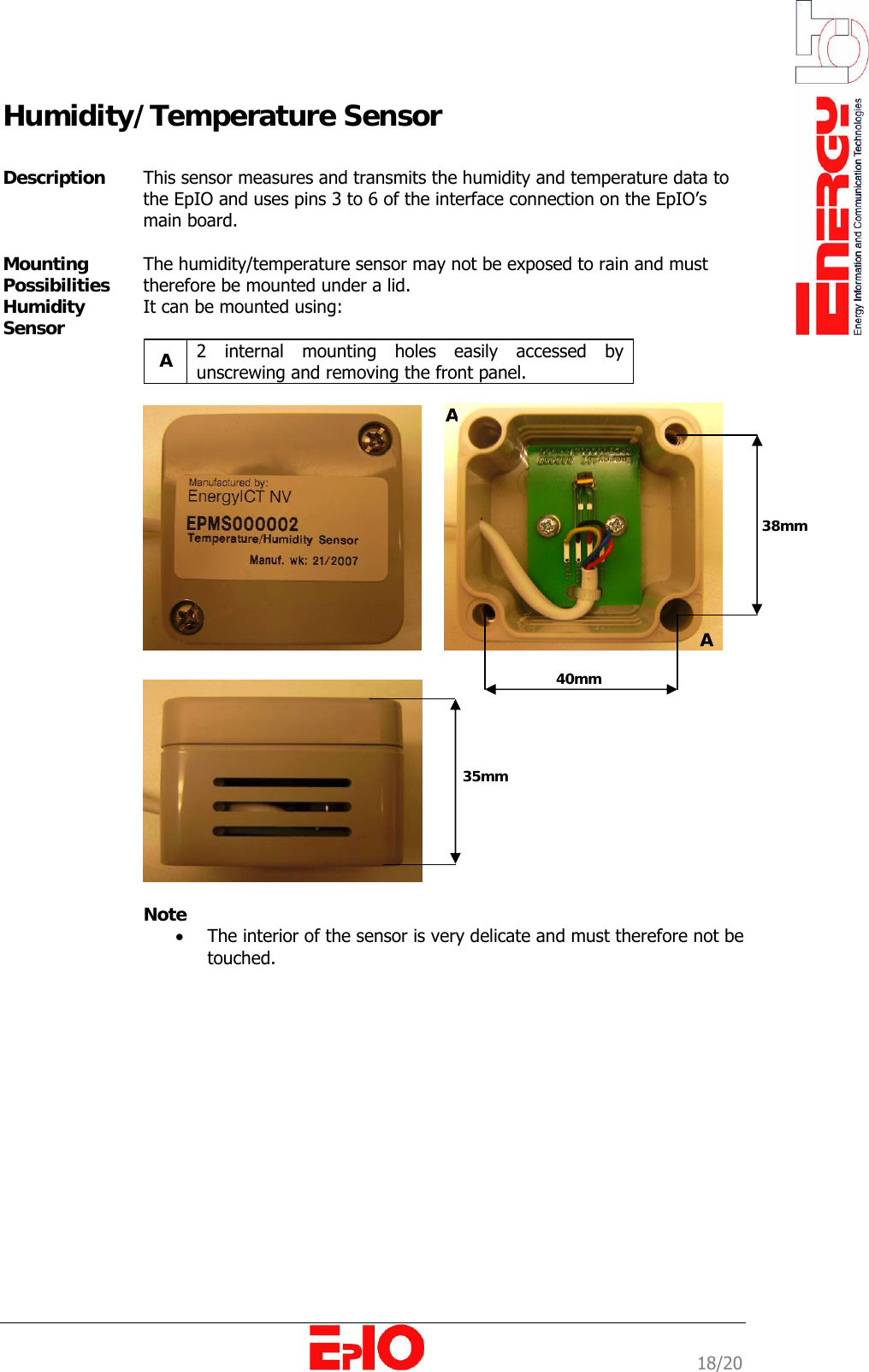
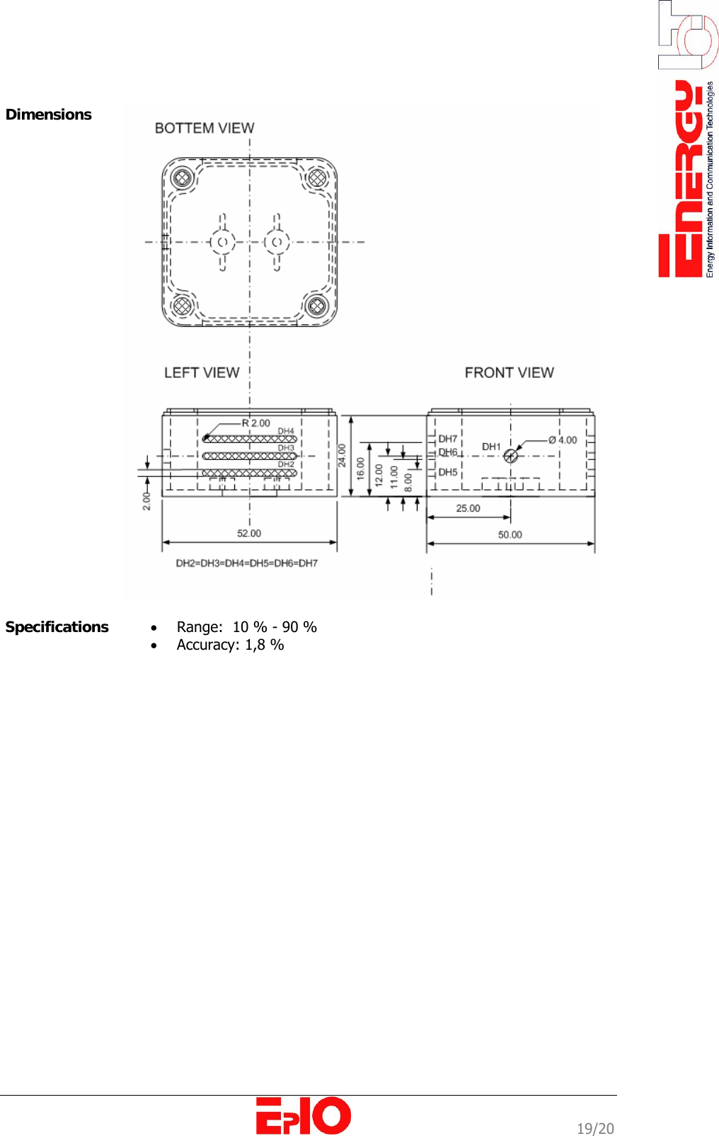
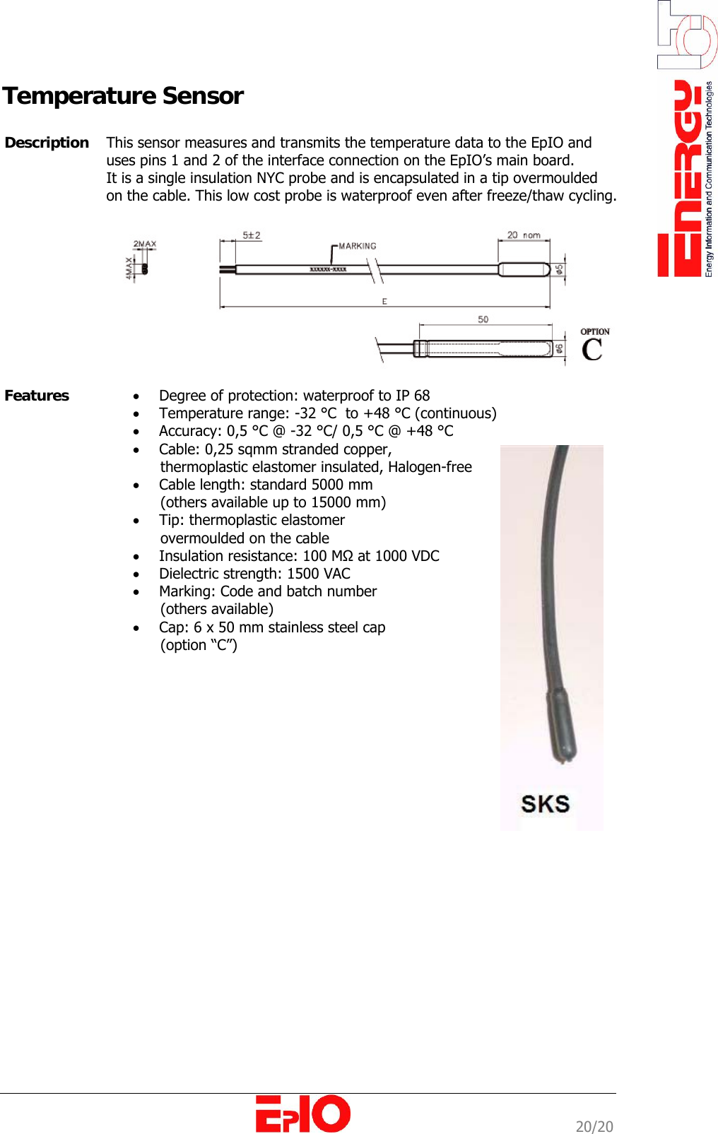
![17/20 Appendix Overview Introduction The appendix provides the user with information on external sensors that can be connected to the EpIO. Chapter description This chapter describes the following topics: Topic Page Humidity/ Temperature Sensor [18] Temperature Sensor [20]](https://usermanual.wiki/EnergyICT-NV/EPIO-RF/User-Guide-898092-Page-19.png)