EnergyICT NV EPIO-RF EPIO-RF User Manual EMNL000015 05 EN EpIO
EnergyICT NV EPIO-RF EMNL000015 05 EN EpIO
Users manual

EpIO
Installation Manual
Serial Number
Article Code
EINF100004
Document Code
EMNL000015_05_EN EpIO
EnergyICT n.v. – Th. Sevenslaan 104A - B-8500 Kortrijk - Tel: +32 56 245 694 (support) - Fax: +32 56 245 699
www.EnergyICT.com - support@EnergyICT.com

Copyright
EnergyICT n.v. Copyright 2007 by EnergyICT n.v. All rights reserved. The information in this document is subject to
change without notice and does not represent a commitment on the part of EnergyICT. The software described in
this document is furnished under a license agreement, and may be used or copied only in accordance with the terms
of that agreement. No part of this document may be reproduced, transmitted, transcribed, stored in any retrieval
system, or translated into any language by any means, electronic or mechanical, including photocopying and
recording, for any purpose other than the licensee's personal use without the express written permission of
EnergyICT. In no event will EnergyICT be responsible for any damages, including any lost profits, lost savings or
other incidental or consequential damages arising out of the use of this product.
Disclaimer
The information contained in this message (including any attachments) is confidential and intended solely for the
attention and use of the named addressee(s). It must not be disclosed to any person without our authority. If you
are not the intended recipient, please delete it from your system immediately - any disclosure, copying or distribution
thereof or any action taken or omitted to be taken in reliance thereon is prohibited and may be unlawful.

1/20
Table of Contents
Safety Precautions .................................................................................................2
Notice on Interference ...........................................................................................3
Power Supply Wiring Safety Guidelines ....................................................................4
Chapter 1: Introduction .................................................................................. 5
About the EpIO .....................................................................................................6
Components..........................................................................................................8
Chapter 2: Mounting and Wiring................................................................... 11
Mounting Instructions .......................................................................................... 12
Power Supply Wiring Instructions.......................................................................... 14
Wiring Instructions .............................................................................................. 15
Chapter 3: Digital Outputs ............................................................................ 16
Appendix ....................................................................................................... 17
Humidity/Temperature Sensor .............................................................................. 18
Temperature Sensor ............................................................................................ 20

2/20
Safety Precautions
Precautions The EpIO has been designed and tested in accordance with the
EN61000-6-4 norm and the EN61000-6-2 norm and has left the factory in a
safe condition.
The present installation manual contains important information and
warnings which have to be followed by the user to ensure safe operation
and to retain the unit in safe condition.
Interventions Any interventions to the EpIO must be done by technical service staff only.
Note
Changes or modifications not expressly approved by the responsible
party for compliance (EnergyICT®) could void the user's authority
to operate the equipment.
Removing the
protective
panel
Before removing the protective panel, make sure the device power is
switched off.
Note
The protective panel can only be opened by qualified electricians.
Distance
Limitations Depending on the location, the distance to a remote node should be no
more than 100 – 150 meters.
3/20
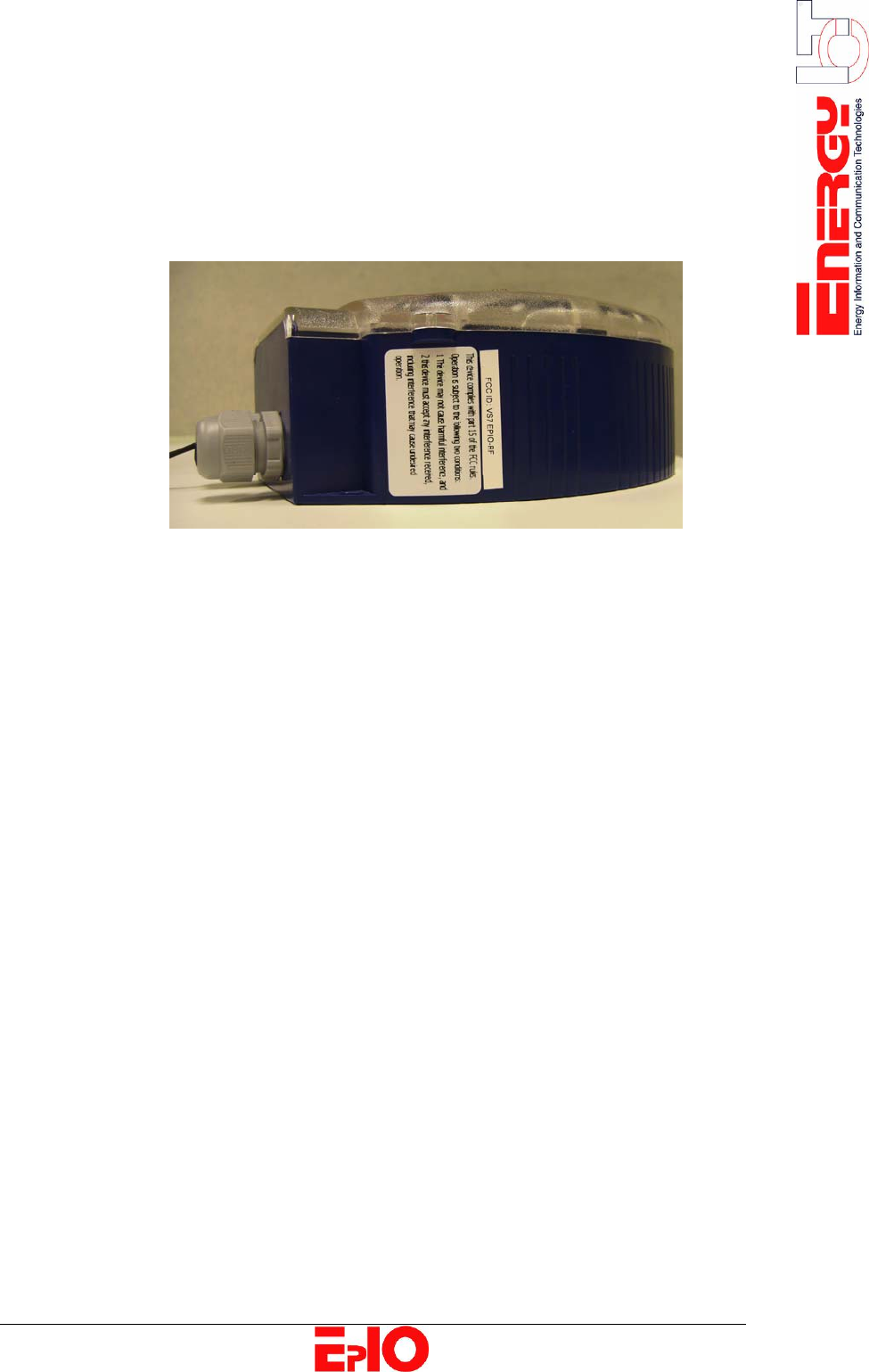
Notice on Interference
Class B digital
device
This equipment has been tested and found to comply with the limits for a
Class B digital device, pursuant to part 15 of the FCC rules. These limits
are designed to provide reasonable protection against harmful interference
in a residential installation.
Use of radio
frequency
energy
This device generates, uses and can radiate radio frequency energy and, if
not installed and used in accordance with the instructions, may cause
harmful interference to radio communications.
However, there is no guarantee that interference will not occur in a
particular installation.
Preventing
interference
If this equipment does cause harmful interference to radio or television
reception, which can be determined by turning the equipment off and on,
the user is encouraged to try to correct the interference by one or more of
the following measures:
• Reorient or relocate the receiving antenna
• Increase the distance between the equipment and the receiver
• Connect the equipment into an outlet on a circuit different from
that to which the receiver is connected.
• Consult the dealer or an experienced radio/TV technician for help.

4/20
Power Supply Wiring Safety Guidelines
Securing the
device To ensure safe operation, the EpIO must be secured externally 16A
maximum.
Switch For safety reasons, the EpIO must be installed close to an easily
accessible switch that removes power from the device.
Wiring The following additional guidelines must be taken into account:
• The power supply wiring must be double isolated
• The power supply wiring must be mechanically secured.
Protective
earth The power supply must be connected to the power connector of the EpIO,
preferably by means of solid wiring. The device must be properly
grounded, using the power connector’s protective earth pin.
Caution
The power wiring must guarantee a permanent connection to the
protective earth.

5/20
Chapter 1: Introduction
Overview
Introduction This chapter provides the user with an introduction to the EpIO, its main
internal components and its main functions.
Chapter
description
This chapter describes the following topics:
Topic Page
About the EpIO [6]
Components [8]
6/20
About the EpIO
Purpose The EpIO designed by EnergyICT® serves as the last point in the meter
reading chain, just before the meter itself. EpIO’s are manufactured as
universal models for all energy meters and contain multiple interfaces
towards the meters. These devices can be used to monitor temperature and
humidity as well.
Network Setup Ideally, multiple EpIO’s are used in combination with a master data
concentrator (RTU+® V6, WebRTU® Z2 or RTU+® Server). The network
between the data concentrator and the EpIO’s is self-forming and self-
healing, with the data concentrator acting as central master and the EpIO’s
acting as slaves. It is self-forming because after installation, each device
auto-configures itself and detects if any devices are in the vicinity, thereby
creating a network capable of expanding itself without any manual
intervention. Each EpIO sends its consumption data via RF directly or
indirectly to the data concentrator. Indirect communication is possible
thanks to the dual role of the EpIO: It can send its own data to the data
concentrator but can also act as a repeater for the data of another EpIO
simultaneously. Moreover, the network is self-healing due to automatic
repair when one device fails (due to disconnection, fire, etc…): a remote
EpIO simply detects another EpIO in its vicinity to send its data to.
This network communication is very similar to the one used by routers on
the Internet, that communicate amongst each other and update their
internal routing tables, in order to recalculate a new routing path should a
router fail. But contrary to this mesh-networking by routers, EpIO’s can
never serve as master, only as slave or as submaster; in which case a
single EpIO collects the data from multiple EpIO’s before sending it to the
master data concentrator.
Design The EpIO is built into a robust ABS box resisting easily to any industrial
environment.
Main Functions The table below lists the main function of the EpIO:
Function Description
Data transfer The EpIO can transfer data (channel status, pulse
counts...):
• Directly to the master concentrator
(RTU+® V6)
• Indirectly to the master concentrator by sending
the data via other EpIO’s
Control output The master concentrator can drive the EpIO to turn
certain loads on or off via the EpIO’s digital outputs.
Types/options After the assembly of the EpIO no changes can be made to the unit.
Take in consideration the type and option you want before ordering.
The table below lists the 2 EpIO types:
Article Code Description
EINF100004 INF EpIO 2DO RF
EINF100005 INF EpIO 2DO 2DI RS485 Mbus RF
7/20
This manual only describes the EINF100004 EpIO. For the
EINF100005 EpIO, please refer to the appropriate manual.
Both types are capable of monitoring temperature and humidity, by
using the required sensor:
Article Code Description
EPMS000001 INF Temp Sensor EpIO
EPMS000002 INF Temp Humid Sensor EpIO
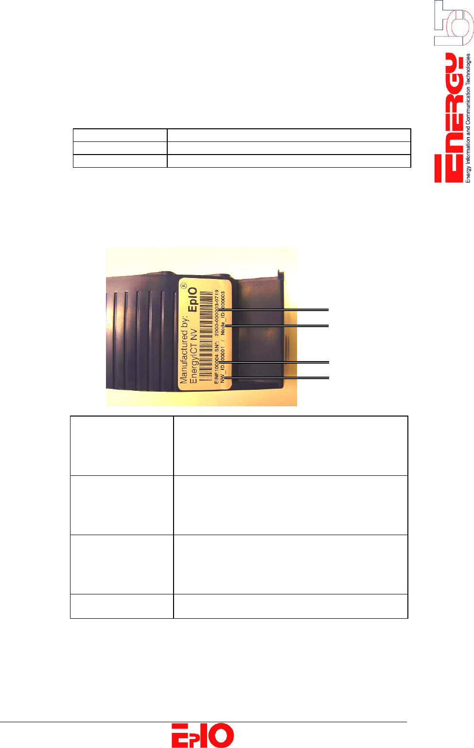
Serial Number Indication
The serial number of the EpIO consists of 14 digits divided into 3
groups. It can be found on the bottom left side of the box, as shown
in the image below:
A. Serial number XXXX – YYYYYY – ZZZZ
• XXXX: Family Type
• YYYYYY: Unique Serial Number
• ZZZZ: Production Week
B. NW_ID
(Network ID) Must be the same for all EpIO’s connected to the
same network.
This number can be found on the status page of
the RTU+® V6 data concentrator.
C. Node_ID
= YYYYYY
= Unique Serial
Number
Must be different for all EpIO’s connected to the
same network.
This number can also be found on the status page
of the RTU+® V6 data concentrator.
D. Article code The code of the product type.
A
C
D
B
8/20
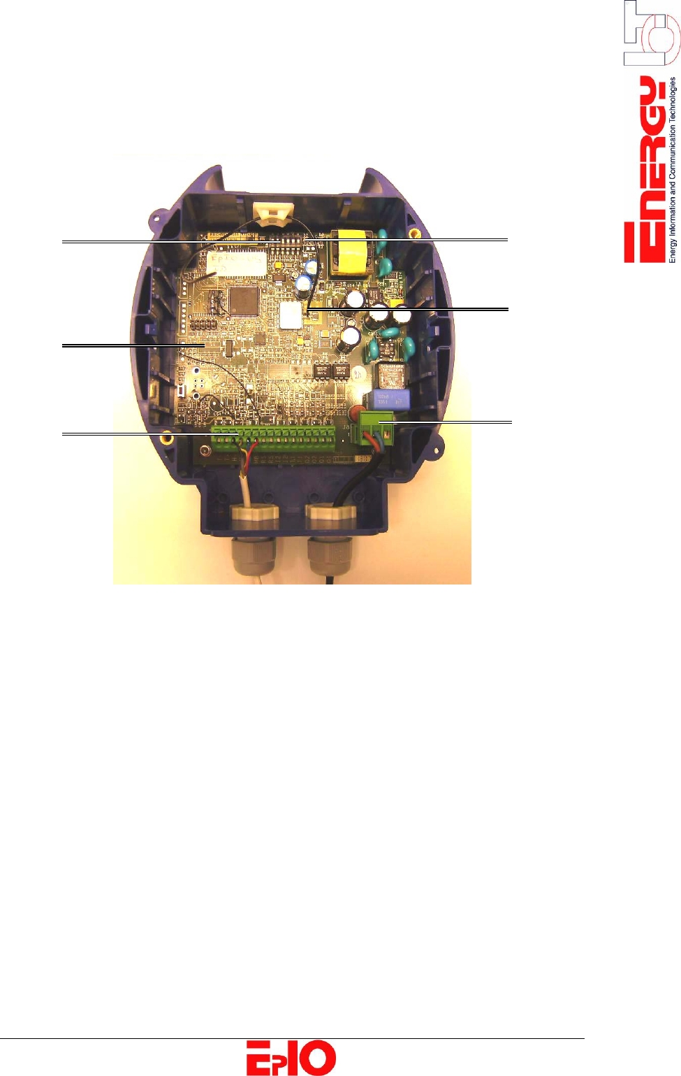
Components
Overview The illustration below displays the main components of the EpIO:
A. Dipswitches B. Main board
C. Interface connector D. LED’s
(2 digital outputs)
E. Antenna F. AC power connector
Basic components The EpIO consists of the following basic components:
• ABS box
• Main board with power supply (plus interface connector)
Power Supply The EpIO is equipped with a 115/230 VAC connector. Power can be
applied in a range from 115 VAC to 230 VAC (± 10 %), to the internal
logic and digital output logic without setting a voltage selector (cfr.
RTU+® V6) and without changing fuses.
Power Supply
Specifications
• 35 mA (nom. 230 VAC)
• F 500 mA – T 250 V (Slow)
• Average Power Consumption: 6 W
• Maximum Power Consumption: 15 W
A
B
C
D
E
F
9/20
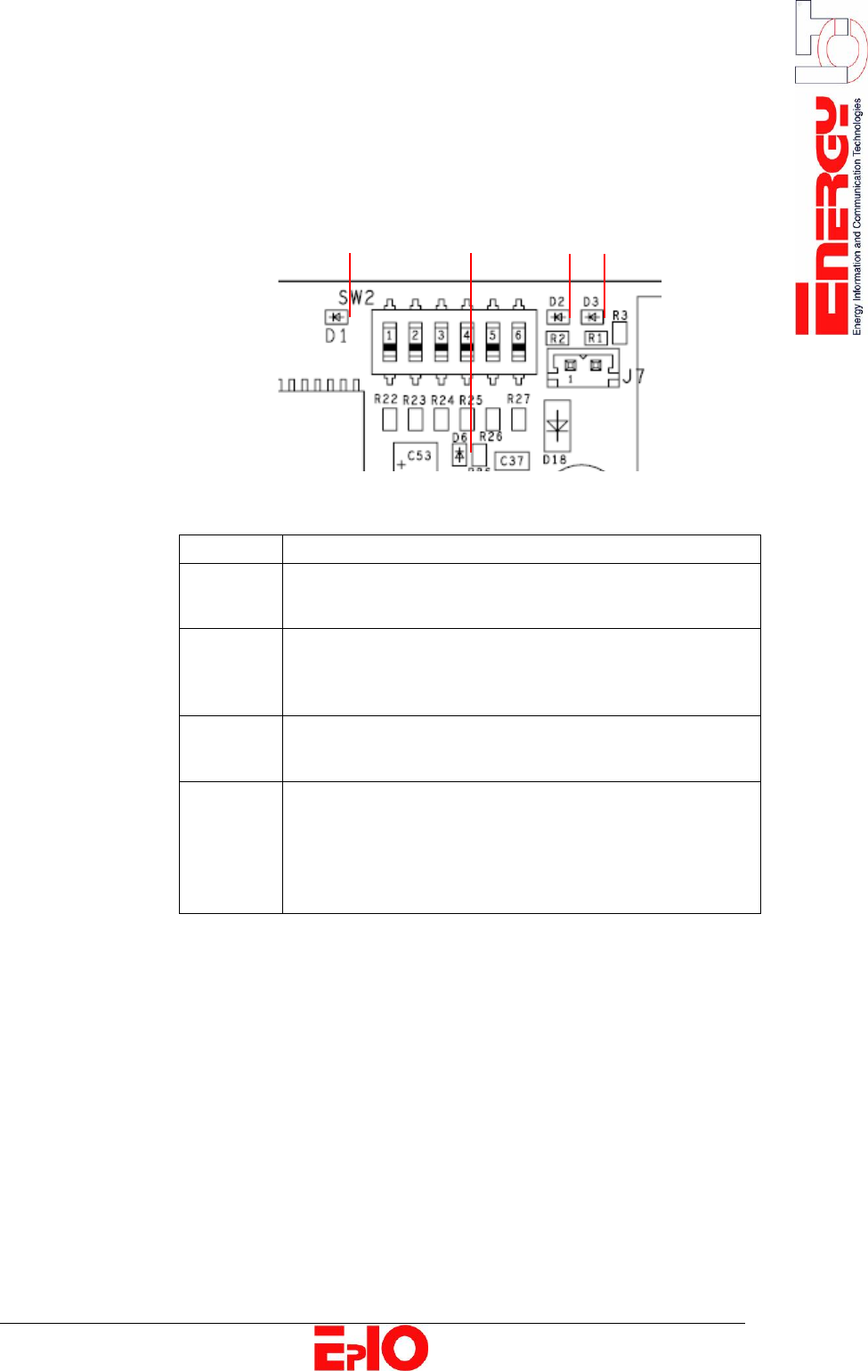
LED description The EpIO is equipped with 4 LED’s.
At startup, the EpIO performs a self-test. When successful, the unit will
start searching for a master (D1). If an error occurs during self-test, a
LED combination will blink slowly (D3). The image below depicts the 4
LED’s on the EpIO PCB.
The table below lists the LED’s from left to right:
LED Description
D1 Transmit LED:
• BLINKING rapidly: searching for Master
D4 Power LED:
• ON: power is ON
• OFF: power is OFF
D2 Receive LED:
• BLINKING: receiving data
D3 Status LED
• BLINKING: wiring fault with Temperature /
Humidity Sensor: probe not found
• ON: connected to Master
• OFF: not connected to Master
D1 D4 D2 D3
10/20
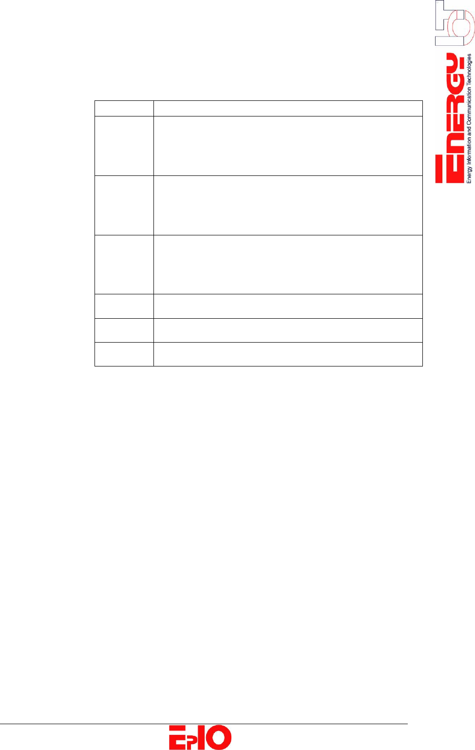
Dipswitches The EpIO is equipped with 6 dipswitches as well, depicted in the image
on the previous page. The table below lists the dipswitches from left to
right:
Dipswitch Description
SW1 Factory Test
• ON: for factory testing (not applicable)
• OFF: in normal usage
SW 1 must always be turned OFF
SW2 Bandwidth Selection
• ON: limited bandwidth
• OFF: full bandwidth
SW 2 must always be turned OFF
SW3 Digital Loopback
• ON: activated
• OFF: disabled
SW 3 must always be turned OFF
SW4 Don’t care
SW5 Don’t care
SW6 Don’t care
11/20
Chapter 2: Mounting and Wiring
Overview
Introduction This chapter provides information on the physical installation of the EpIO
device, including mounting and wiring instructions.
Chapter
description
This chapter describes the following topics:
Topic Page
Mounting Instructions [12]
Power Supply Wiring Instructions [14]
Wiring Instructions [15]
Protective Panel
12/20
Mounting Instructions
Location The EpIO does not need to be mounted in an electricity box or meter box;
it can be mounted “stand alone”. To ensure a safe installation, keep all
regulations applicable in your location into account.
Mount on
a panel
The EpIO box must be mounted on a vertical panel or wall.
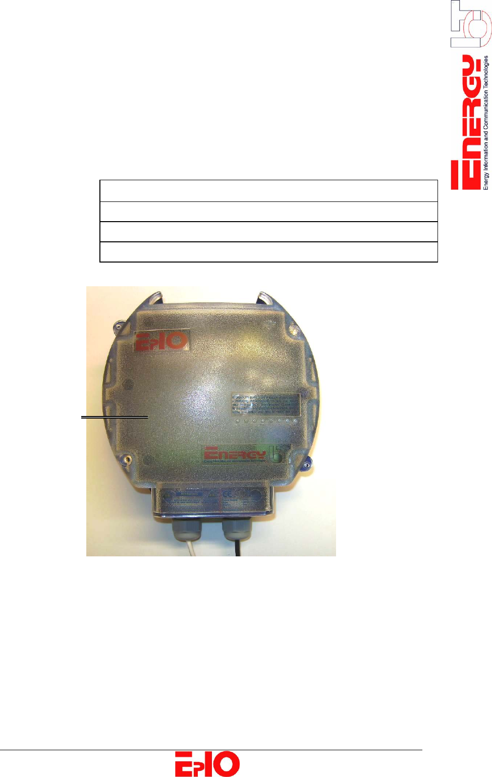
Protective panel The interior of the EpIO is protected from outside influences by a
protective plastic panel.
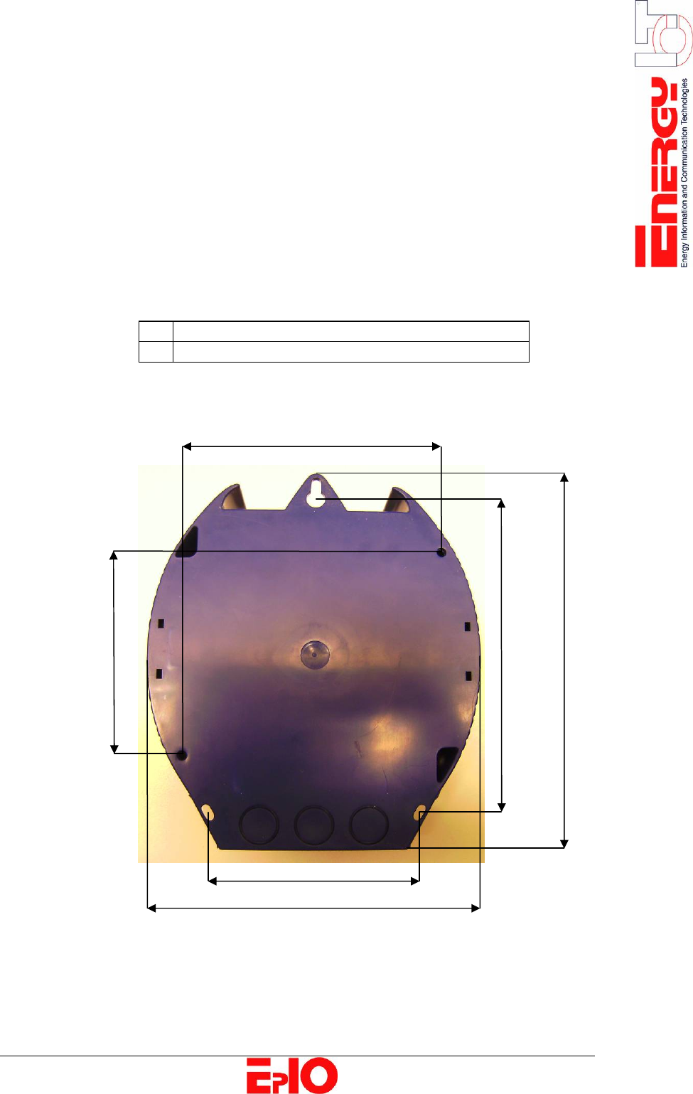
Mounting
Possibilities
EpIO
The EpIO can be mounted using
A 3 external mounting holes
B 2 internal mounting holes
You should remove the protective panel of the EpIO before you begin
mounting the device to the vertical panel. This makes the internal
mounting holes easily accessible.
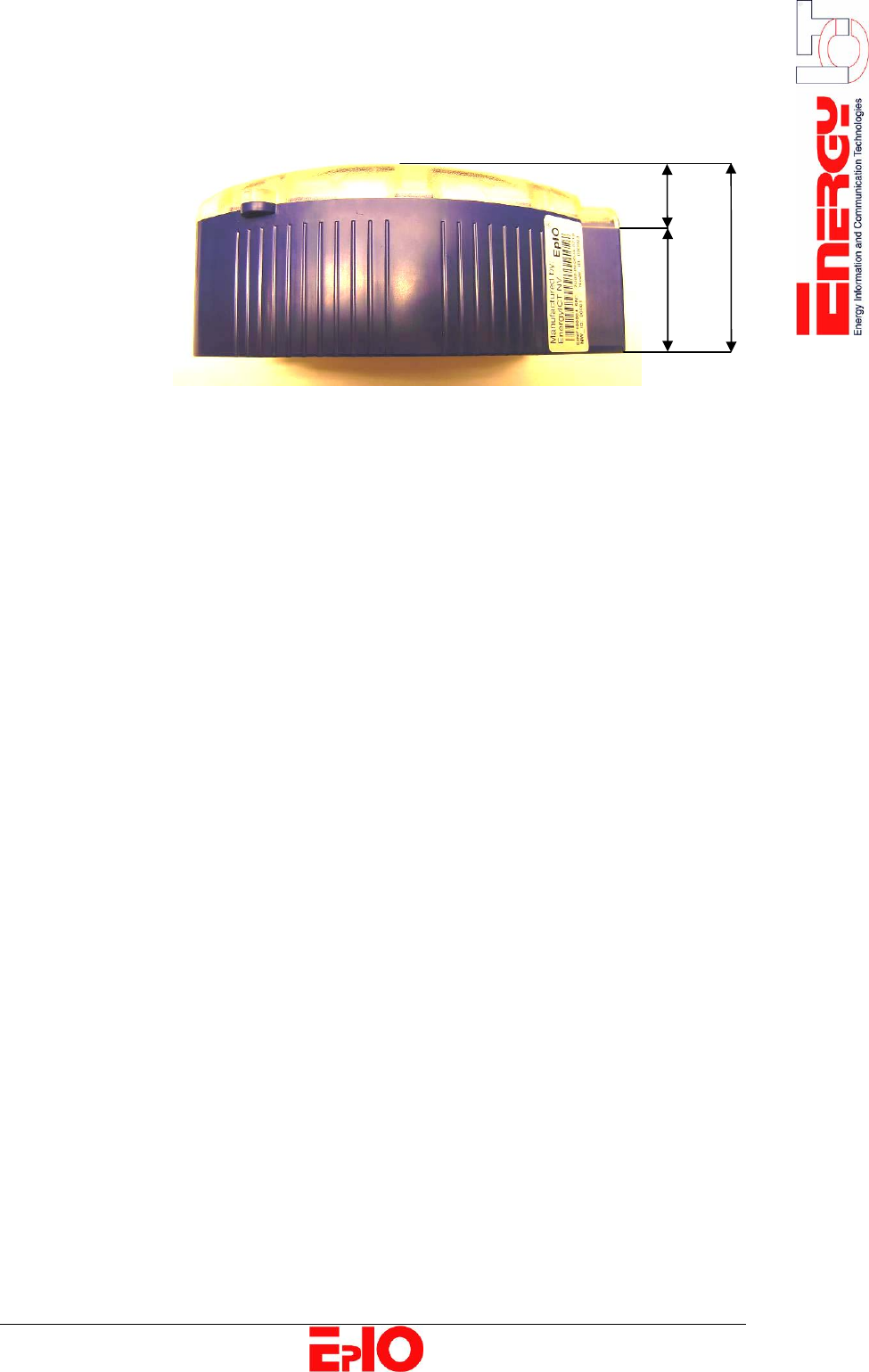
160mm
135mm
140mm
85mm
110mm
85mm
B
B
A
A
A
13/20
65mm
18mm
47mm
14/20
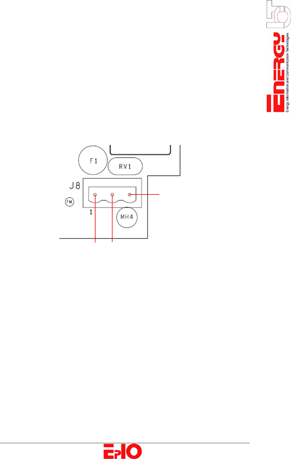
Power Supply Wiring Instructions
Power connector The power supply connectors are located at the bottom right corner of
the EpIO. The EpIO has a 115/230 AC connector (switched mode power
supply).
Single wire or
two wires
The connector accepts single wires (0,2 to 2,5 mm²)
and two wires (0,2 to 1,0 mm²).
Fuse The fuse used in the EpIO is the T 500 mA /250 V (slow) and is located
close to the power connector (Labeled with ‘F1’).
Connecting the
power Connect the electrical wire to the connector carefully.
A. Protective earth pin
B. L1 pin
C. L2 pin
A
C B
15/20
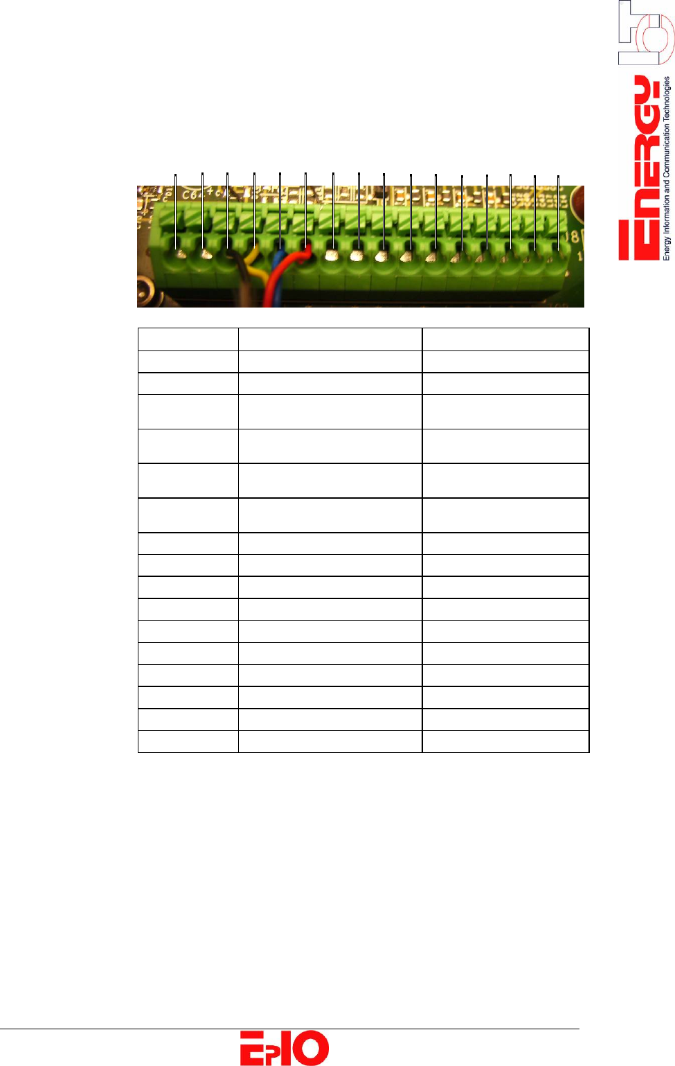
Wiring Instructions
Wiring
instructions Connect the interface as follows:
1 2 3 4 5 6 7 8 9 10 11 12 13 14 15 16
Connection Description Purpose
1 T - Temperature Sensor
2 T + Temperature Sensor
3 H - Humidity Sensor
• Black: ground
4 H + Humidity Sensor
• Yellow: data
5 MB - Humidity Sensor
• Blue: clock
6 MB + Humidity Sensor
• Red: +3V3
7 RS - Not used
8 RS + Not used
9 INP2 + Not used
10 INP2 - Not used
11 INP1 + Not used
12 INP1 - Not used
13 OUTP2 + Digital Output 2
14 OUTP2 - Digital Output 2
15 OUTP1 + Digital Output 1
16 OUTP1 - Digital Output 1
16/20
Chapter 3: Digital Outputs
Overview
Introduction The EnergyICT® EpIO is configured with two digital outputs.
Purpose The outputs are designed for AC or DC power, and are not polarized. They
can switch between a 50 V signal and a maximum current of 600 mA.
Digital output
specifications
The table below lists the digital output specifications:
Digital output specifications
• Maximum voltage secured by a varistor to 50 V
• Maximum switch current: 600 mA per output
• Non-polarized outputs
• Isolation voltage: 3750 VRMS
17/20
Appendix
Overview
Introduction The appendix provides the user with information on external sensors that
can be connected to the EpIO.
Chapter
description
This chapter describes the following topics:
Topic Page
Humidity/ Temperature Sensor [18]
Temperature Sensor [20]
18/20
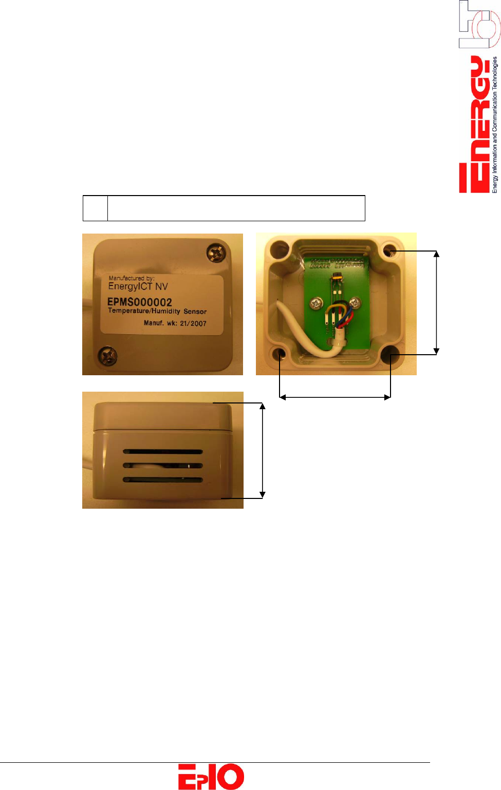
Humidity/Temperature Sensor
Description This sensor measures and transmits the humidity and temperature data to
the EpIO and uses pins 3 to 6 of the interface connection on the EpIO’s
main board.
Mounting
Possibilities
Humidity
Sensor
The humidity/temperature sensor may not be exposed to rain and must
therefore be mounted under a lid.
It can be mounted using:
A 2
internal mounting holes easily accessed by
unscrewing and removing the front panel.
Note
• The interior of the sensor is very delicate and must therefore not be
touched.
38mm
40mm
A
A
35mm
19/20
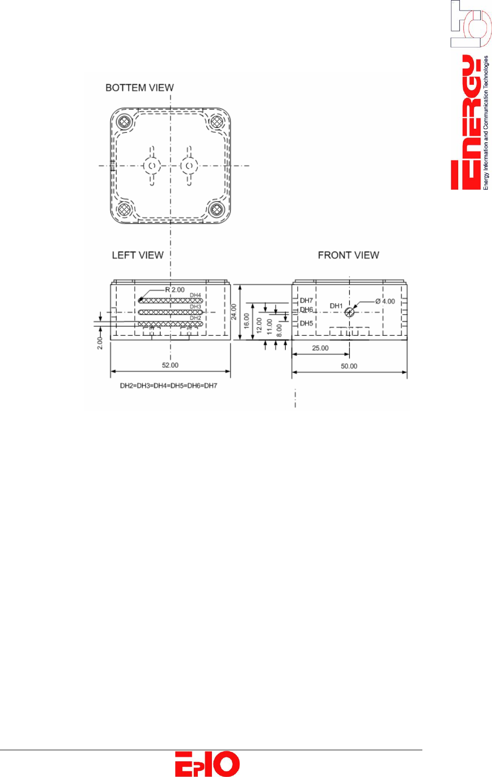
Dimensions
Specifications
• Range: 10 % - 90 %
• Accuracy: 1,8 %
20/20
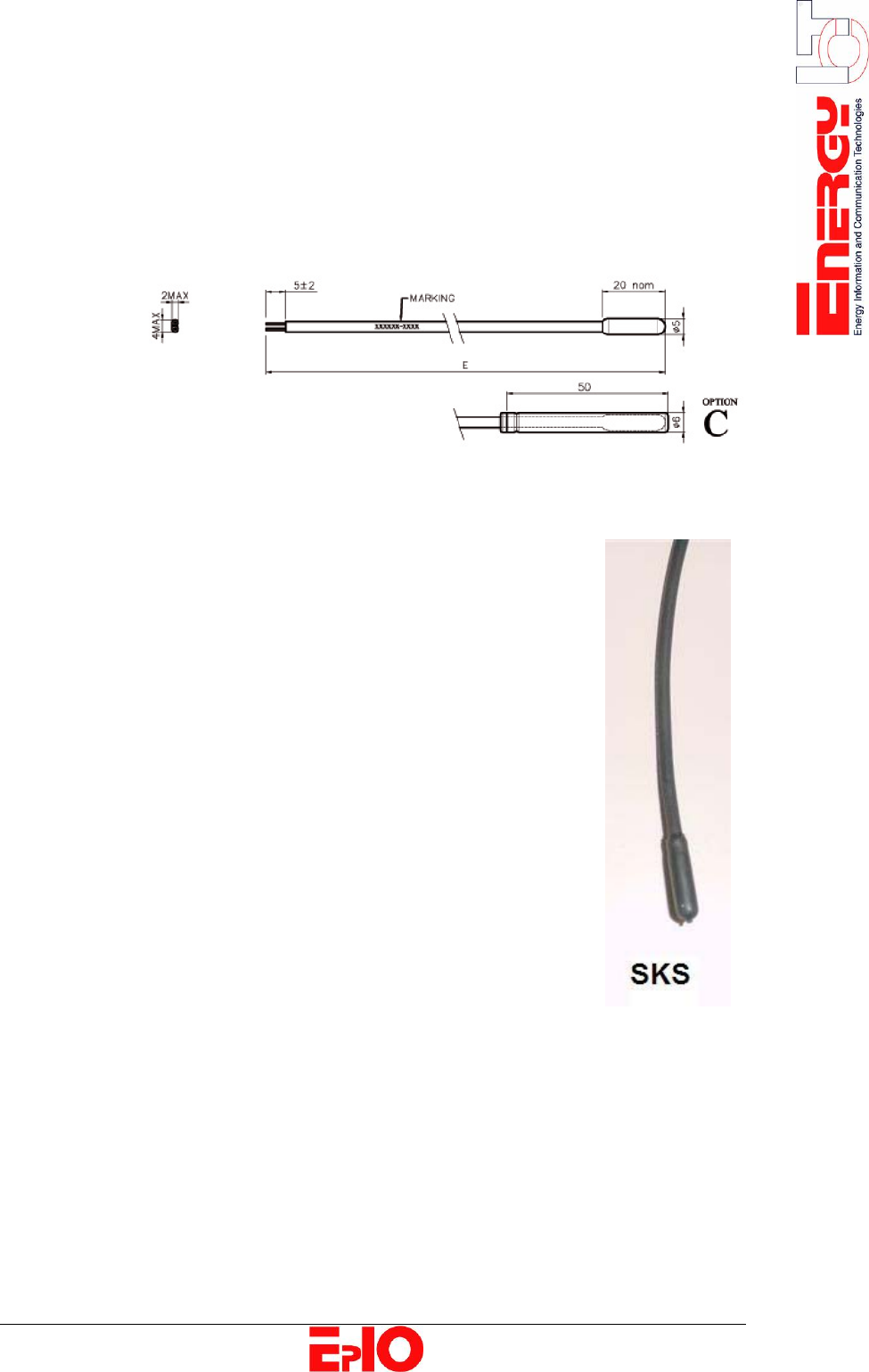
Temperature Sensor
Description This sensor measures and transmits the temperature data to the EpIO and
uses pins 1 and 2 of the interface connection on the EpIO’s main board.
It is a single insulation NYC probe and is encapsulated in a tip overmoulded
on the cable. This low cost probe is waterproof even after freeze/thaw cycling.
Features • Degree of protection: waterproof to IP 68
• Temperature range: -32 °C to +48 °C (continuous)
• Accuracy: 0,5 °C @ -32 °C/ 0,5 °C @ +48 °C
• Cable: 0,25 sqmm stranded copper,
thermoplastic elastomer insulated, Halogen-free
• Cable length: standard 5000 mm
(others available up to 15000 mm)
• Tip: thermoplastic elastomer
overmoulded on the cable
• Insulation resistance: 100 MΩ at 1000 VDC
• Dielectric strength: 1500 VAC
• Marking: Code and batch number
(others available)
• Cap: 6 x 50 mm stainless steel cap
(option “C”)