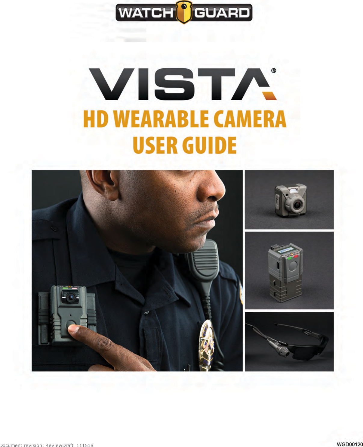
Enforcement Video VST100 VISTA WiFi User Manual VISTA Wearable Camera User Guide

Enforcement Video, LLC (d.b.a. WatchGuard Video) VISTA WiFi VISTA Wearable Camera User Guide

user manual

Document revision: ReviewDraft_111518
Important NoticeCopyright © 2018 WatchGuard, Inc. All rights reserved. This document and supporting data arethe exclusive property of WatchGuard, Inc. and may not be copied and/or reproduced withoutpermission.Firmware updatesWatchGuard is committed to the continual testing and improvement of our firmware. As newfirmware revisions become available, these updates will be made available to your agency; feesmay apply depending on your licensing agreement.Contact informationWatchGuard, Inc.415 East Exchange ParkwayAllen, Texas 75002Customer Service: 1-800-605-6734Customer Service web portal: https://support.watchguardvideo.com/hc/en-usSend us your suggestionsTell us about your experiences and how you are using the VISTA Body Camera. We will do ourbest to accommodate suggestions you may have in future revisions.U.S. customers, call Customer Service or submit a ticket through the Customer Service webportal. International customers, contact your local distributor or submit a ticket through theCustomer Service web portal.Trademark noticeVELCRO® is a registered trademark of Velcro Industries B. V.RAM® is a registered trademark of National Products Inc. in the United States and/or othercountries.iPhone® is a trademark of Apple Inc., registered in the U.S. and other countries.Wi-Fi® is a registered trademark of Wi-Fi Alliance.Oakley and Flak Jacket® are trademarks or registered trademarks of Oakley, Inc. in the U.S.and other countries.Littelfuse® is a registered trademark of Littelfuse, Inc. in the United States and othercountries.Sierra Wireless® and AirLink® are registered trademarks of Sierra Wireless.All other marks, names, and logos are the property of their respective owners.iiVISTA Body CameraWGD00120 RevisionReviewDraft_111518
FCC and ICnoticesThis equipment complies with Part 15 of the FCC rules and Industry Canada licence-exemptRSS standard(s). This equipment should only be used with the antenna supplied byWatchGuard Video. Any changes or modifications not expressly approved by the manufacturercould void the user's authority to operate the equipment.VISTA WiFi contains the following IDs:FCC ID: YJV-VST100IC: 9073A-VST-100VISTA XLT contains the following IDs:FCC ID: YJV-VST200IC: 9073A-VST-200Cet appareil est conforme à la Partie 15 des règlements de la FCC et Industrie Canada exemptsde licence standard RSS. Cet appareil doit être utilisé uniquement avec l'antenne fournie parWatchGuard Video. Tout changement ou modification non expressément approuvée par lefabricant pourrait annuler l'autorité de l'utilisateur de faire fonctionner l'appareil.VISTA WiFi contient les identifiants suivants:FCC ID: YJV-VST100IC: 9073A-VST-100VISTA XLT contient les identifiants suivants:FCC ID: YJV-VST200IC: 9073A-VST-200The device complies with Part 15 of the FCC rules and Industry Canada license-exempt RSSstandard(s) subject to the following two conditions:1. The device may not cause harmful interference.2. The device must accept all interference received, including interference that may causeundesired operation.Cet appareil est conforme à la Partie 15 des règlements de la FCC et Industrie Canada exemptsde licence standard RSS soumis aux deux conditions suivantes:1. Cet appareil ne peut causer des interférences nuisibles.2. Cet appareil doit accepter toutes les interférences reçues, y compris les interférences quipeuvent perturber le fonctionnement.Under Industry Canada regulations, this radio transmitter may only operate using an antennaof a type and maximum (or lesser) gain approved for the transmitter by Industry Canada. Toreduce potential radio interference to other users, the antenna type and its gain should be sochosen that the equivalent isotropically radiated power (e.i.r.p.) is not more than thatnecessary for successful communication.Conformément à la réglementation d'Industrie Canada, cet émetteur radio ne peut fonctionnerà l'aide d'une antenne d'un type et maximum (ou moins) Gain approuvé pour l'émetteur parIndustrie Canada. Pour réduire le risque d'interférence avec d'autres utilisateurs, le typed'antenne et son gain doivent être choisis afin que la puissance isotrope rayonnée équivalente(PIRE) ne dépasse pas ce qui est nécessaire pour une communication réussie.iiiVISTA Body CameraWGD00120 RevisionReviewDraft_111518
The radio transmitters IC:9073A-VST100 and IC: 9073A-VST-200 have been approved byIndustry Canada to operate with the antenna types listed below with the maximum permissiblegain and required antenna impedance for each antenna type indicated. Antenna types notincluded in this list, having a gain greater than the maximum gain indicated for that type, arestrictly prohibited for use with this device.lAntenna type (radio transmitter): WatchGuard Video part number WGP01589-200, 2.2 dbigain, 50 Ohm impedanceCes émetteurs radios IC:9073A-VST-100 et IC: 9073A-VST-200 ont été approuvés par“Industry Canada” pour fonctionner avec les types d'antennes énumérés ci-dessous avec legain maximal admissible et l'impédance d'antenne requise pour chaque type d'antenne indiqué.Les types d'antennes ne figurant pas dans cette liste, ayant un gain supérieur au gainmaximum indiqué pour ce type, sont strictement interdits pour une utilisation avec cetappareil.lType d'antenne (émetteur radio): WatchGuard Video part number WGP01589-200, 2.2 dBigain, 50 Ohm impedanceThe antennas used for this transmitter must not be co-located or operating in conjunction withany other antenna or transmitter.Les antennes utilisées pour cet émetteur ne doivent pas être co- Les antennes utilisées pourcet émetteur ne doivent pas être co-localisées ou fonctionner conjointement avec une autreantenne ou un autre émetteur.This device complies with Health Canada’s Safety Code. The installer of this device shouldensure that RF radiation is not emitted in excess of the Health Canada’s requirement.Information can be obtained at https://www.canada.ca/en/health-canada/services/environmental-workplace-health/reports-publications/radiation/safety-code-6-health-canada-radiofrequency-exposure-guidelines-environmental-workplace-health-health-canada.htmlCet appareil est conforme avec Santé Canada Code de sécurité 6. Le programme d’installationde cet appareil doit s’assurer que les rayonnements RF n’est pas émis au-delà de l’exigence deSanté Canada. Les informations peuvent être obtenues:https://www.canada.ca/en/health-canada/services/environmental-workplace-health/reports-publications/radiation/safety-code-6-health-canada-radiofrequency-exposure-guidelines-environmental-workplace-health-health-canada.htmlCE Declaration of ConformityIn accordance with the requirements of Radio Equipment Directive 2014/53/EU, Annex III,Module B, section 3(c), WatchGuard Video declares that the radio equipment has been designedin accordance with harmonized standards and a full review of the equipment against therequirements of the following standards has been conducted. We confirm that the equipment isfully within the scope of these standards.lETSI EN 301 489-17, V3.1.1: 2017lETSI EN 300 328, V2.1.1: 2016lEN 55024:2010lEN 55032:2012/AC:2013lIEC 60950-1:2005 (Second Edition); Am1:2009 + Am2:2013ivVISTA Body CameraWGD00120 RevisionReviewDraft_111518
ContentsContentsIntroduction 11About this document 11Related documents and information 12What's new for version 3 12What's new for version 3.0.2: 12What's new for version 3.0.0: 12Using the VISTA Body Camera 13Overview 14Basic workflow 14Wearing VISTA and VISTAWiFi 15Using the rotatable shirt clip and duty belt clip 15Using the locking chest mount 16Using the MOLLE vest loop mount 17Other VISTAand VISTA WiFi mounts 18Wearing VISTA XLT 19Recommended mounting order for VISTA XLT system 19Wearing the DVR 20Using the DVRbelt clip 20Using the DVR belt holster 20Wearing the head-mounted camera sensor 21Using the glasses mount 21Preparing your Oakley glasses 21Wearing the body-mounted camera sensor 22Using the magnetic mount 22Using the shirt clip 23Powering On and Off 24Powering on 24Powering off 24Forcing power off 25Starting and Stopping a Recorded Event 26VISTA Body CameraWGD00120 RevisionReviewDraft_111518v
ContentsStarting a recorded event manually 26Stopping a recorded event manually 27Muting the Audio During a Recorded Event 28Muting audio 28Categorizing a Recorded Event 29Categorizing a recorded event on the camera 29Docking the VISTA Body Camera 30Docking the VISTA Body Camera in a USB Base 31Undocking the camera from the USB Base 32Docking the VISTA Body Camera in a VISTA Transfer Station 33Docking the VISTABody Camera in a WiFi Base 34Provisioning the camera 35VISTA Body Camera configuration 35Uploading events 37VISTA and VISTAWiFi 38VISTA XLT 38Record-After-the-Fact® events 39Clearing video out of camera storage 39Upgrading firmware 40VISTA and VISTAWiFi 41VISTAXLT 41Charging the battery 42VISTA and VISTAWiFi 43VISTAXLT 43VISTA WiFi and VISTAXLT: Associating with a recording group 44About the VISTA Body Camera 45Overview 46Video, Audio, and Subtitle Evidence 46Video 47Audio 47Subtitles 47VISTA and VISTA WiFi 48Camera sensor and lens 49Microphone 49viVISTA Body CameraWGD00120 RevisionReviewDraft_111518
ContentsButtons 49Power button 49Record Start/Stop button 50Display Backlight button 50Display 50VISTA XLT 52Camera sensor 52Buttons 53Power button 53Record Start/Stop button 53Display Backlight button 54Display 54Information Sequence 56VISTA and VISTA WiFi 56VISTA XLT 56Feedback indicators 57Storage 57VISTAand VISTA WiFi 58VISTA XLT 58Low storage and full storage messages 58Battery 59VISTA and VISTAWiFi 59VISTA XLT 60LOW BATT/LOW BATTERY message 60LOW BASE message 60OVERTEMP message 61Wi-Fi 61VISTA WiFi 62VISTAXLT 62GPS 62VISTA WiFi 63VISTA XLT 63Quick mounting latch 63USB Base 64VISTA Body CameraWGD00120 RevisionReviewDraft_111518vii
ContentsConnections 64Setting up the VISTA USB Base 64VISTA Transfer Station 65LEDs 65Connections 65Setting up the VISTA Transfer Station 66VISTA WiFi Base 66LEDs 67Connections 68Setting up the VISTA WiFi Base 68VISTABody Camera Special Features 69Overview 70Recording special features 70Battery and storage saving special features 70Covert Mode 71Pre-Event Capture 71Audio 71Record-After-the-Fact® 72Generating an RATF event 72Storage 72Audio 73Force Microphone On 73Sleep Power State 74Sleep warning period 74Exiting Sleep state 74Automatic Off 75Automatic off warning period 75Maximum Recorded Event Time 76Maximum Recorded Event Time warning period 76Recording Reminder Alert 77Covert Mode 77Using VISTAWiFi or VISTA XLT with a Recording Group 79Overview 80Recording groups 81viiiVISTA Body CameraWGD00120 RevisionReviewDraft_111518
ContentsMembers of the recording group 81Smart Power Switch 824RE DVR 82VISTA WiFi Base 83VISTA WiFi and VISTA XLT 84Other devices in the system 85Group recordings 85VISTA WiFi and VISTA XLT behavior during a group recording 86Appendix A: Using VISTA SmartConnect 89SmartConnect Overview 90Activating the VISTA WiFi or VISTA XLT hotspot 91No cameras found 92Controlling battery usage 92Disconnecting SmartConnect 93Standard disconnect 93Nonstandard disconnect 93Connecting to VISTA SmartConnect 94Connecting VISTA WiFi or VISTA XLT to SmartConnect for the first time 94Connecting VISTA WiFi or VISTA XLT to SmartConnect after the first time 97Reviewing VISTAWiFi or VISTA XLT Recorded Events 98Capturing snapshots 98Categorizing Recorded Events 99Live Streaming 101Covert Mode 102Starting and Stopping Recorded Events 102SmartConnect Settings 104Camera Settings 104Camera Data 105Appendix B: Using the Quick Connect Mobile Charger 107FCC Rules compliance 107Overview 108Mobile Charger Parts 108Mobile Charger base 109Mobile Charger cable 109VISTA Body CameraWGD00120 RevisionReviewDraft_111518ix
ContentsCable connection end 11012 V cigarette-lighter plug 110Using the Mobile Charger 111Appendix C: Upgrading VISTA, VISTAWiFi, and VISTA-Related Devices 113Upgrading VISTA or VISTA WiFi to Firmware Version 2.2.0 114Upgrading the VISTA WiFi Base and the Smart Power Switch 115Upgrading VISTA or VISTA WiFi from a Pre-v2.0.2 Firmware Version 116Appendix D: VISTA Transfer Station Setup 117Overview 118VISTA Transfer Station Hardware 119Setting up the hardware 119VISTATransfer Station Configuration 121Transfer Station Settings 121Static IP 121DHCP and Date/Time Settings 122VISTASettings 122DHCP 122Static IP 123Transfer Station administrative functions 123Upgrading the Transfer Station software or firmware 123Changing the login credentials for the Transfer Station configuration page 124Disabling the configuration page 124Restarting the Transfer Station 125Configuring the Transfer Station 125Index 129xVISTA Body CameraWGD00120 RevisionReviewDraft_111518
IntroductionIntroductionWelcome to the WatchGuard® VISTA HD Wearable Camera User Guide. This guide is designedto walk you through the basics of using your VISTA® Body Camera to collect video and audioevidence.About this documentThe VISTA HD Wearable Camera User Guide covers the basic components and operation ofVISTA, VISTA WiFi, and VISTA XLT™ including:lDocking, charging, provisioning, and uploadinglAssociating with a recording group (VISTA WiFi and VISTA XLT only)lWearing the VISTA Body CameralPowering on and offlRecording evidencelCategorizing eventsThis guide includes a section on VISTA Body Camera special features:lPre-event and Record-After-the-Fact® (RATF)lAutomatic sleep and power off to help you save batterylMaximum recording length and periodic recording alerts to help you save storage spacelCovert ModeThis guide also includes a section on recording groups and how VISTA WiFi or VISTA XLT and theWiFi Base work within a local recording group network.Four appendices to the guide contain:lInstructions for using the VISTA SmartConnect smartphone app with VISTA WiFi or VISTA XLTlInstructions for using the VISTA Quick Connect Mobile Charger with extended-capacity VISTAor VISTA WiFilInstructions for special upgrades of the VISTA Body Camera and related deviceslInstructions for setting up the VISTA Transfer StationNote: This user guide covers the basic use of the VISTA Body Camera. It is not acomprehensive manual for every possible action or situation you couldexperience when using the camera. If you have a question about the VISTA BodyCamera that is not covered in the user guide, contact your WatchGuardrepresentative.VISTA Body CameraWGD00120 RevisionReviewDraft_11151811
IntroductionRelated documents and informationFor subjects related to your WatchGuard system that are not covered by the VISTA HDWearable Camera User Guide, see the following documents:l4RE® In-Car Video User GuidelEvidence Library 4 Web User GuidelEvidence Library Express User Guidel4RE Vehicle Installation InstructionsWhat's new for version 3What's new for version 3.0.2:lSupport for upload from the vehicle using a cellular LTE connectionVersion 3.0.2 gives you the option to upload events from a VISTA Body Camera, docked in theWiFi Base, over a cellular LTE connection to the Evidence Library 4 Web (EL4 Web) uploadserver.WatchGuard supports upload over a cellular connection using the Sierra Wireless® AirLink®MG90 High Performance Multi-Network Vehicle Router.The camera must be configured to upload events to EL4 Web from the WiFi Base.lBattery metrics improvementslPerformance and security enhancementslBug fixesWhat's new for version 3.0.0:lSupport for VISTA XLT (page 52)Version 3 gives you the option to use VISTA XLT as part of your fleet of WatchGuard devices.VISTA XLT is a two-piece body-worn camera system with an HD camera sensor separate fromthe camera DVR. It includes Wi-Fi® and GPS.lSupport for the VISTAQuick Connect Mobile Charger (page 107)Version 3 gives you the option to use the VISTA Quick Connect Mobile Charger with extended -capacity VISTA and VISTA WiFi. The VISTA Quick Connect Mobile Charger is an in-vehiclecharging base that uses a cable to connect to a vehicle's 12 V cigarette-lighter receptacle. It cancharge a worn VISTA Body Camera while the camera is recording, then be disconnected quicklyif needed.Important! The VISTA Quick Connect Mobile Charger is NOT supportedwith standard-capacity VISTA or VISTA XLT.12VISTA Body CameraWGD00120 RevisionReviewDraft_111518
Using the VISTA Body CameraUsing the VISTA Body CameraIn this section...lBasic workflow (page 14)lWearing VISTA and VISTA WiFi (page 15)lWearing VISTA XLT (page 19)lPowering the camera on and off (page 24)lRecording evidence (page 26)lCategorizing a recorded event (page 29)lDocking the camera (page 30)oIn the USB base (page 31)oIn the VISTA Transfer Station (page 33)oIn the VISTA WiFi Base (page 34)oProvisioning (page 35)oUploading recorded events from storage (page 37)oUpgrading firmware (page 40)oCharging the battery (page 42)oVISTA WiFi and VISTA XLT: Associating with a recording group (page 44)VISTA Body CameraWGD00120 RevisionReviewDraft_11151813
Using the VISTA Body CameraOverviewYou use the VISTA Body Camera as a DVR (digital video recorder) to capture, process, and storevideo and audio evidence. You connect the camera with your Evidence Library software toprovision it as well as to upload its video for evidence management.WatchGuard offers three types of VISTA Body Camera:lVISTA: All-in-one HD body camera that does not include Wi-Fi® or GPSlVISTA WiFi: All-in-one HD body camera that includes Wi-Fi and GPSlVISTA XLT: Two-piece body camera system with an HD camera sensor separate from thecamera DVR; it includes Wi-Fi® and GPSIf your agency is using VISTA WiFi or VISTA XLT, you can pair the camera with a VISTA WiFiBase that is associated with a 4RE DVR. The devices together form a recording group.Note: If you are not sure whether your equipment has the Wi-Fi feature,contact your WatchGuard representative.Basic workflowThe following steps make up a basic workflow for using the VISTA Body Camera during yourshift:Note: This workflow assumes the VISTA Body Camera battery has been fullycharged before the camera is checked out to start the shift.1. With the VISTA Body Camera in the dock, provision the camera and then check it out usingyour Evidence Library software. (page 35)2. Undock the camera.3. (VISTA XLT only) Connect the sensor head and cable to the main body of the camera, if notalready done. (page 19)4. (VISTA WiFi and VISTA XLT only) Dock the camera in the VISTA WiFi Base (WiFi Base) to pair itwith the base and associate it with the local recording group. (page 44)5. (VISTA WiFi and VISTA XLT only) Undock the camera after it has paired with the WiFi Base.6. Attach VISTA or VISTA WiFi (page 15) or VISTA XLT (page 19) securely to your clothing.7. Start and stop recorded events. (page 26)8. Categorize recorded events. (page 29)9. Power the camera off or on, as needed. (page 24)10. Dock the camera to upload recorded events (page 37) and charge its battery (page 42).14VISTA Body CameraWGD00120 RevisionReviewDraft_111518
Wearing VISTA and VISTAWiFiWearing VISTA and VISTAWiFiVISTA and VISTA WiFi have four main mounting options. The quick mounting latch on VISTAand VISTA WiFi attaches to any of the mounts:lRotatable shirt clip (below)lDuty belt clip (below)lLocking chest mount (page 16)lMOLLE vest loop mount (page 17)Wear VISTA or VISTA WiFi on your clothing where it is most comfortable, convenient, andsecure for you. Make sure that the lens is not obstructed and that it is aimed at the horizon.Using the rotatable shirt clip and duty belt clipThe rotatable clip mount uses a heavy-duty alligator clip thatrotates and slides to make it more convenient for you to securethe camera.The belt clip mountuses an alligator clipwith a hook at the bottom to securely clip the camerato your duty belt.Both clips connect to the camera the same way:1. Match the anchor tab on the back of the clip with theslot on the back of the camera.2. Match the mounting tab on the clip with the quickmounting latch on the camera, then slide the latchover the tab.3. Attach the clip to your clothing or your belt where youwant to wear the camera.VISTA Body CameraWGD00120 RevisionReviewDraft_11151815
Using the VISTA Body CameraUsing the locking chest mountWarning! The chest mount uses magnets to hold the camera in place. Do notwear the chest mount near sensitive medical equipment or implants such aspacemakers or other magnetically programmable medical devices.The chest mount uses magnets and locking pins tosecure the mount to your clothing. When you wearthe chest mount, one bracket goes under your shirt,the other goes over your shirt.Important! Because of the strength of the magnets, separating the bracketsrequires effort. Realigning the brackets causes them to snap together forcefully.To use the chest mount:1. Separate the under-shirt bracket from theover-shirt bracket.2. Match the anchor tab on the over-shirtbracket with the slot on the back of thecamera.3. Match the mounting tab on the over-shirtbracket with the quick mounting latch on thecamera, then slide the latch over the tab.4. Place the under-shirt bracket under yourshirt where you want to wear the camera.5. Place the over-shirt bracket, with the cameraattached, against the under-shirt bracket,with your shirt between them.The magnets on both brackets line upautomatically, securing the mount to yourshirt.6. To lock the mount in place, slide both of the locking pins up into their safety housings.Warning! The chest mount uses magnets to hold the camera in place. Do notwear the chest mount near sensitive medical equipment or implants such aspacemakers or other magnetically programmable medical devices.16VISTA Body CameraWGD00120 RevisionReviewDraft_111518
Using the MOLLE vest loop mountUsing the MOLLE vest loop mountNote: Some of the earliest versions of the VISTA Body Camera do not connect tothe MOLLE vest mount. Please consult with your WatchGuard representative formore information.The MOLLE vest mount uses hooks to anchor VISTA orVISTA WiFi over two rows of loops on the MOLLE vest.Tip: Install the mount on the vest beforeyou connect the camera to the mount.To use the MOLLE vest mount:1. Determine which two rows of loops on the MOLLE vestyou want to use to mount the VISTA Body Camera.2. On the lower of the two rows, slide the forked enddown over the sewn seam between two loops until thehook is engaged below the seam.You may need to slightly twist the mount to help thehook slide over the seam.3. Slightly fold the fabric between the two rows so thatthe upper loop hooks engage two loops on the upperrow of loops.4. Slide the upper loop hooks down over the two loops,straightening the fabric between the rows, to fullyseat the mount.The forked end should be fully engaged with the seamon the lower row of loops. The hooks should be fullyengaged with two loops on the upper row of loops.5. Match the anchor tab on the bottom of the outward-facing plate of the MOLLE vest mount with the bottomslot on the back of VISTA.6. Match the mounting tab on the top of the mount with the quick mounting latch on VISTA,then slide the latch over the tab.Note: The camera connects to the MOLLE vest mount in the same way itconnects to the shirt or belt clip. For more information, see Using the rotatableshirt clip and duty belt clip on page 15.VISTA Body CameraWGD00120 RevisionReviewDraft_11151817
Using the VISTA Body CameraOther VISTAand VISTA WiFi mountsOther mount options include:lVELCRO® plate mount: Works with externally-worn vests with VELCRO surfaceslKlick Fast mount: Works with UK-style Klick Fast receiverslTripod mount: Works on standard mounts with 1/4″-20 threadslRAM® mount: Includes a 1-inch ball for RAM accessoriesContact your WatchGuard representative for information.18VISTA Body CameraWGD00120 RevisionReviewDraft_111518
Wearing VISTA XLTWearing VISTA XLTEach VISTA XLT uses two mounts: one for the DVR and one for the camera sensor.These mounts are available for the DVR:lBelt clip (page 20)lBelt holster (page 20)This mount is available for the head-mounted camera sensor:lGlasses mount (page 21)The glasses mount has been designed to work with Oakley Flak Jacket® glasses.These mounts are available for the body-mounted camera sensor:lMagnetic mount (page 22)lShirt clip (page 23)The DVR connects to the camera sensor using a cable. Various cables and strain-relief clips areavailable.Recommended mounting order for VISTA XLT systemTo wear VISTA XLT:1. Disconnect the cable from the VISTA XLT DVR and camera sensor.2. Mount the DVR and attach it to your belt.3. Mount the camera sensor and attach it to your glasses or clothing as appropriate.4. Connect the camera sensor end of the cable to the camera sensor, then route the cablethrough your clothing toward the DVR as appropriate.Note: The DVR end of the cable is marked with DVR.5. Connect the DVR end of the cable to the DVR.Wear the VISTA XLT DVR and camera sensor where they are most comfortable, convenient,and secure for you. Make sure that the lens is not obstructed and that it is aimed at the horizon.Tip: For specific recommendations on wearing VISTA XLT, review theWatchGuard Online Training Course for VISTA XLT. For access to the trainingcourse, contact WatchGuard Customer Service.VISTA Body CameraWGD00120 RevisionReviewDraft_11151819
Using the VISTA Body CameraWearing the DVRThese mounts are available for the DVR:lBelt cliplBelt holsterUsing the DVRbelt clipTip: Remove VISTA XLT from the belt clip before docking the camera.To use the belt clip:1. Match the anchor tab on the back of the clip with the sloton the back of the VISTA XLT DVR.2. Match the mounting tab on the clip with the quickmounting latch on the DVR, then slide the latch over thetab.3. Attach the clip to your duty belt where you want to wearthe DVR.Using the DVR belt holsterTo use the holster:1. Unsnap the empty holster.2. Slide the VISTA XLT DVR into the holster withthe Record Start/Stop button facing out.3. Snap the holster closed, stretching the elasticover the top of the DVR.4. Thread the holster onto your duty belt whereyou want to wear the DVR.20VISTA Body CameraWGD00120 RevisionReviewDraft_111518
Wearing the head-mounted camera sensorWearing the head-mounted camera sensorThe glasses mount is available for the head-mounted camera sensor.The glasses mount has been designed to workwith Oakley Flak Jacket® glasses, availablethrough WatchGuard.Using the glasses mountTo use the glasses mount for the head-mounted camerasensor:1. If you have not already done so, disconnect thecable from your VISTA XLT DVR and camera sensor.2. On the Oakley glasses provided by WatchGuard,remove the rubber sleeve from the right arm of theframes.For instructions, see Preparing your Oakley glasses below.3. Snap the glasses mount into the groove on the head-mounted camera sensor.4. Slide the quick mounting latch backwards and open the hinged part of the mount.5. Fit the mount over the raised ovals on the bare arm of the Oakley glasses.6. Close the hinged part of the mount then slide the quick mounting latch forward.Preparing your Oakley glassesNote: Oakley glasses are designed for the arms to be removed and the rubbersleeves to be replaced.To prepare your Oakley glasses for mounting:1. Grasp the right arm of the glasses near the frameand, with gentle force, twist the arm to snap it outof the frame.2. Slide the rubber sleeve off of the arm and set itaside.3. Snap the arm back into the glasses frame.VISTA Body CameraWGD00120 RevisionReviewDraft_11151821
Using the VISTA Body CameraWearing the body-mountedcamera sensorThese mounts are available for the body-mountedcamera sensor:lMagnetic mountlShirt clipUsing the magnetic mountWarning! The magnetic mount uses magnets to hold the body-mountedcamera sensor in place. Do not wear the mount near sensitive medicalequipment or implants such as pacemakers or other magnetically programmablemedical devices.To use the magnetic mount for the body-mountedcamera sensor:1. If you have not already done so, disconnect thecable from your VISTA XLT DVR and camerasensor.2. Separate the under-shirt bracket from the over-shirt bracket.Separating the brackets requires some effort.3. On the over-shirt bracket, slide out both latches.4. Snap the body-mounted camera sensor into theover-shirt bracket, then push in the slidinglatches.5. Place the under-shirt bracket under your shirt where you want to wear the camera sensor.6. Place the over-shirt bracket, with the camera sensor attached, against the under-shirt bracket,with your shirt between them, making sure the camera sensor LED is at the top.22VISTA Body CameraWGD00120 RevisionReviewDraft_111518
Using the shirt clipUsing the shirt clipTo use the shirt clip for the body-mounted camera sensor:1. If you have not already done so, disconnect the cablefrom your VISTA XLT DVR and camera sensor.2. Slide out the latch on the clip.3. Snap the body-mounted camera sensor into the clip (inany orientation), then slide in the latch.4. Attach the shirt clip to your clothing where you want towear the camera sensor, making sure the camerasensor LED is at the top.VISTA Body CameraWGD00120 RevisionReviewDraft_11151823
Using the VISTA Body CameraPowering On and OffYou use the Power button to power the VISTA Body Camera on andoff. The Power button is on the bottom of VISTA, VISTA WiFi, and theVISTA XLT DVR.Powering onTo power the camera on:nWith the power off, press and release the Power button.The camera goes through its booting and information sequences.When it is ready to use, the display shows the number of events instorage and the green LED lights steadily. Ascending tones sound (depending on yournotification selections).Tip: (VISTA XLT) Press the Display Backlight button to advance through theinformation sequence screens.(VISTA XLT) If the camera sensor is not connected to the DVR, the display reads CameraUNPLUGGED. When you connect the camera sensor to the DVR, the display readsCONNECTING, then shows the number of events in storage and the green LEDs light steadily.Powering offNote: The VISTA Body Camera can be configured to power off automatically if itis left idle (no movement and/or button presses) for a period of time. For moreinformation, see Automatic Off on page 75.To power the camera off:nWith the power on, press and release the Power button two times within 5 seconds.After you press and release the Power button the first time, the display reads OFF? 2X (VISTAand VISTA WiFi) or OFF? Press Again (VISTA XLT) to confirm that you want to power thecamera off.Once you press the Power button the second time, the display reads SHUTTING DOWN andthe green LED turns off. Descending tones sound (depending on your notification selections).Important! If you do not press the Power button a second time within 5seconds, the display clears, and you need to start the power off sequence again.24VISTA Body CameraWGD00120 RevisionReviewDraft_111518
Forcing power offForcing power offIn the rare case where the VISTA Body Camera stops responding to commands (or ifWatchGuard Technical Services instructs you to), you can force the camera to power off.Warning! Avoid forcing the VISTA Body Camera to power off, if at all possible.Forcing the camera's power off can, in rare cases, result in data corruption.To force the VISTA Body Camera to power off:nPress and hold the Power button until the camera powers off, about 15 seconds.Note: If you have forced the camera's power off, WatchGuard recommends thatyou dock it in a USBBase as soon as it is feasible. Docking the camera in a USBBase allows VISTA to repair itself.VISTA Body CameraWGD00120 RevisionReviewDraft_11151825
Using the VISTA Body CameraStarting and Stopping a Recorded EventTypically, you use a Record Start/Stop button to start or stop arecorded event on the VISTA Body Camera. The RecordStart/Stop button is on the front of VISTA and VISTA WiFi.VISTA XLT has two Record Start/Stop buttons, one on thefront of the DVR and one on each camera sensor.If your VISTA WiFi or VISTA XLT is a member of arecording group, the camera can start or stop a recorded eventautomatically when alerted by another group member that theother group member has started or stopped an event. For moreinformation on recording groups, see Using VISTAWiFi or VISTAXLT with a Recording Group on page 79.If your VISTA WiFi is connected to the VISTA SmartConnect smartphone app, youcan start or stop a recorded event using SmartConnect. For more information on using thesmartphone app, see Starting and Stopping Recorded Events on page 102.Starting a recorded event manuallyTo manually start a recorded event on the VISTA Body Camera:nPress a Record Start/Stop button.(VISTA/VISTA WiFi) The display shows the REC icon and therecording length, then begins to blink the REC icon. The redLED lights steadily and ascending tones sound with a vibration(depending on your alert notification selections).(VISTA XLT) The display reads RECORDING, then begins toblink the dot in the REC icon and show the recording length.The red LEDs light steadily and ascending tones sound with avibration (depending on your alert notification selections).As the recorded event continues, the display shows the currentrecorded event length increasing every second and the storageindicators updating as needed.Note: A VISTA WiFi or VISTA XLT that has automatically started an eventbehaves in the same way.26VISTA Body CameraWGD00120 RevisionReviewDraft_111518
Stopping a recorded event manuallyStopping a recorded event manuallyNote: The VISTA Body Camera can be configured to NOT allow manual eventstop. If you cannot manually stop the camera, when you press a RecordStart/Stop button, two low tones sound with a vibration (depending on youralert notification selections) and the display reads IGNORED for 3 seconds.To manually stop a recorded event on the VISTA Body Camera:nPress a Record Start/Stop button.Important! You may need to press a Record Start/Stop button a second timewithin 5 seconds to confirm the event stop, depending on your configuration.The REC icon turns off on the display and the red LED turns off. Descending tones sound with avibration (depending on your alert notification selections).After a recorded event has stopped, if event categorization is required as part of the camera'sconfiguration, the event categorization sequence starts. For instructions how to categorize arecorded event, see Categorizing a Recorded Event on page 29.Note: A VISTA WiFi or VISTA XLT that has automatically stopped an eventbehaves in the same way.The VISTA Body Camera can be configured to stop a recorded event automatically after a periodof time. For more information, see Maximum Recorded Event Time on page 76.Tip: Even if VISTA WiFi or VISTA XLT is NOT configured to require an event-stopconfirmation (second press of a Record Start/Stop button within 5 seconds),you need to confirm an event stop in the following scenario:VISTA WiFi or VISTA XLT automatically starts an event because a member of thelocal recording group reports that it started a recorded event. You immediately(within 10 seconds) press a Record Start/Stop button to STOP the recordedevent because you do not want VISTA WiFi or VISTA XLT to record it. The camerarequests that you press a Record Start/Stop button again to confirm that youwant to STOP the recorded event. If you do not press the button a second timewithin 5 seconds, VISTA WiFi or VISTA XLT continues to record the event.VISTA Body CameraWGD00120 RevisionReviewDraft_11151827
Using the VISTA Body CameraMuting the Audio During a Recorded EventNote: The ability to mute a VISTA Body Camera during a recorded event is set upas part of a configuration in WatchGuard Evidence Library software.You can use the Display Backlight button on the VISTA BodyCamera to mute the audio during a recorded event. TheDisplay Backlight button is on the right side as you look atthe front of the VISTA, VISTA WiFi, or VISTA XLT DVR.If the camera is configured to allow muting, when you pressand hold down the Display Backlight button during anevent, the camera mutes the event audio. As long as youcontinue to hold the Display Backlight button, the audio ismuted. When you release the button, the event audiocontinues normally.Muting audioTo mute audio during a recorded event:1. Press and hold down the Display Backlight button.2. Continue to hold down the Display Backlight button as long as you want the event audio toremain muted.The display reads MUTED while you hold down the Display Backlight button.The camera's audio unmutes when you release the Display Backlight button.Tip: You cannot mute the audio while you are categorizing a recorded event.Selecting a category requires that you hold down the same button (DisplayBacklight) you hold down for muting. Once you have finished categorizing, youcan again mute the audio. For information on categorizing a recorded event onthe VISTA Body Camera, see Categorizing a Recorded Event on page 29.28VISTA Body CameraWGD00120 RevisionReviewDraft_111518
Categorizing a Recorded EventCategorizing a Recorded EventNote: Event categorization is set up as part of a configuration in WatchGuardEvidence Library software.You use the Display Backlight button on the VISTA BodyCamera to select a category to apply to a recorded event. TheDisplay Backlight button is on the right side as you look atthe front of the VISTA, VISTA WiFi, or VISTA XLT DVR.If the camera is configured to require categorization, whenyou stop an event, the display immediately prompts you toselect an event category.If your VISTA WiFi or VISTA XLT is a member of arecording group, the camera can automatically accept anevent category from the 4RE DVR group member as its owncategory. However, any category selected directly on VISTAWiFi or VISTA XLT overrides the 4RE category. For moreinformation on recording groups, see Using VISTAWiFi orVISTA XLT with a Recording Group on page 79.If your VISTA WiFi or VISTA XLT is connected to theVISTA SmartConnect smartphone app, you cancategorize an event using SmartConnect. Any category selected on SmartConnect overrides a4RE category. If you categorize an event on both the VISTA WiFi camera and the smartphoneapp, the last selected category, regardless of the device, will be applied to the event. For moreinformation on using the smartphone app, see Categorizing Recorded Events on page 99.Categorizing a recorded event on the cameraTo categorize a recorded event:1. Stop the event manually or allow VISTA WiFi or VISTA XLT to stop the event automatically.The display shows the Category prompt.2. Press and release the Display Backlight button as many times as needed to move throughthe list of available event categories, one at a time.3. Press and hold the Display Backlight button for at least 2 seconds when the event categoryyou want to select shows on the display.The display reads SAVED and shows which category you selected. One long tone sounds witha vibration (depending on your alert notification selections).If another recorded event starts (manually or automatically) while the camera is in the middleof the event categorization sequence, the camera aborts the sequence and starts the newevent. You will be able to categorize the recorded event later in your Evidence Library software,if necessary.VISTA Body CameraWGD00120 RevisionReviewDraft_11151829
Using the VISTA Body CameraDocking the VISTA Body CameraWatchGuard offers three different bases where you can dock your VISTA Body Camera:lUSB Base (page 31)lVISTA Transfer Station (page 33)lVISTA WiFi Base (page 34)Docking the camera allows you to perform the following tasks:lUpload recorded events from storage (page 37)lUpgrade firmware (page 40)lCharge the battery (page 42)Use the USB Base or the Transfer Station inside your agency when fully charging the battery.Use the WiFi Base in the vehicle for incidental charging during your shift. Charging in a vehiclebase can impact the vehicle battery and can slow down significantly in warmer temperatures.Important! Battery charging shuts down at ambient temperaturesgreater than 35 degrees C (95 degrees F).lProvision the camera (USB Base and Transfer Station only) (page 35)lDefine a Record-After-the-Fact®(RATF) event (USB Base only) (page 39)lRequest a state capture for troubleshooting (USB Base only)lAssociate with a recording group that can include a 4RE DVR and other VISTA WiFi or VISTA XLTcameras (WiFi Base only) (page 44)The VISTA Body Camera needs to interact with Evidence Library software to be customized foryour agency. For that interaction to take place, the camera must be docked in a VISTA USBBase or Transfer Station connected to your Evidence Library software.You can dock any VISTA Body Camera in any of the three bases.30VISTA Body CameraWGD00120 RevisionReviewDraft_111518
Docking the VISTA Body Camera in a USB BaseDocking the VISTA Body Camera in a USB BaseWhen you dock the VISTA Body Camera in a USB Base connected to Evidence Library software:Caution: To prevent possible damage to some computers, connect the USBBase to the computer through the approved USB hub (Sabrent 7-Port USB 2.0Hub, WatchGuard part number WGP02364).lThe camera's battery begins to charge, if neededlVISTA's time and date synchronize with the Evidence Library system, if needed (VISTA only)Important! VISTA (no Wi-Fi® and GPS) sets its internal date and timefrom the Evidence Library software's computer. If the computer's dateand time is set incorrectly, VISTA's will be set incorrectly, and your videoevidence will be marked with the incorrect date and time.lThe camera's firmware upgrades, if a firmwareupgrade has been staged on the cameralThe camera communicates to the EvidenceLibrary software that it has recorded events touploadlRecorded events are uploaded to the EvidenceLibrary softwarelThe Evidence Library software sendscommands and/or requests to the camera asapplicable:oMark any imported recorded events asimport confirmedoUpdate the configurationoStage a firmware upgradeoGenerate an RATF eventoGenerate a state captureWhen you undock the camera from the USB Base, it processes the Evidence Library softwarecommands and requests before it is ready for normal operation.VISTA Body CameraWGD00120 RevisionReviewDraft_11151831
Using the VISTA Body CameraUndocking the camera from the USB BaseEvidence Library software commands and requests are only applied when the camera isundocked from a USB Base. When you undock the camera, it processes the commands andrequests in the following order, as applicable:1. Performs a state capture.The display reads STATE CAPTURE.2. Updates the configuration.The display reads CONFIG. The configuration update alert sounds when the update isfinished.3. Generates an RATF event.The display reads CREATING RATF.Note: After the RATF event has been generated, the camera starts theevent categorization sequence for the RATF event if it is configured torequire event categorization. For instructions how to categorize anevent, see Categorizing a Recorded Event on page 29.4. Unprotects the recorded events confirmed as imported.This makes the storage space available to be reused as needed.5. Stages the firmware upgrade to perform the next time the camera is docked.Once all the commands and requests are processed, VISTA is ready for normal operation.For more information about the USB Base, see USB Base on page 64.32VISTA Body CameraWGD00120 RevisionReviewDraft_111518
Docking the VISTA Body Camera in a VISTA Transfer StationDocking the VISTA Body Camera in a VISTA Transfer StationNote: The VISTA Transfer Station must be set up and configured to be used withyour Evidence Library software. For instructions how to set up the TransferStation, see Appendix D: VISTA Transfer Station Setup on page 117.When you dock the VISTA Body Camera in a Transfer Station connected to Evidence Librarysoftware:lThe camera's battery begins to charge, if neededlVISTA's time and date synchronize with the Evidence Library system, if needed (VISTA only)Important! VISTA (no Wi-Fi® and GPS) sets its internal date and timefrom the Evidence Library software's computer. If the computer's dateand time is set incorrectly, VISTA's will be set incorrectly, and your videoevidence will be marked with the incorrect date and time.lThe camera's firmware upgrades, if afirmware upgrade has been staged on thecameralThe camera communicates to the EvidenceLibrary software that it has recorded eventsto uploadlRecorded events are uploaded to theEvidence Library softwarelEvidence Library software sends commandsand/or requests to the camera as applicable:oMark any imported recorded events asimport confirmedThe events confirmed as imported areimmediately unprotected. This makesthe storage space available to be reusedas needed.oUpdate the configurationIf the configuration is manually pushed to the camera (through the Evidence Librarycheckout process), the configuration is updated immediately.If the configuration is automatically pushed to the camera, the configuration isupdated after the camera is undocked.oStage a firmware upgradeThe firmware upgrade is staged on the camera immediately, and then is applied the nexttime the camera is docked.When you undock the camera from the Transfer Station, it is ready for normal operation.For more information about the Transfer Station, see VISTA Transfer Station on page 65.VISTA Body CameraWGD00120 RevisionReviewDraft_11151833
Using the VISTA Body CameraDocking the VISTABody Camera in a WiFi BaseNote: Not all VISTA Body Cameras or VISTA bases have the Wi-Fi® feature. Formore information, contact your WatchGuard representative.When you dock the VISTA Body Camera in a VISTA WiFi Base:lThe camera's battery begins to charge, if neededlThe camera's firmware upgrades, if a firmware upgradehas been staged on the cameralVISTA WiFi or VISTA XLT pairs with the WiFi Base; whenit does, it becomes associated with the local recordinggroup (VISTA WiFi and VISTA XLT only)When the camera becomes associated with the localrecording group, it is disassociated from any otherrecording group.When you dock the VISTA Body Camera in a VISTAWiFi Basethat is connected to an Evidence Library 4 Web upload server:Note: WatchGuard recommends that you use version 4.2 (or later) of EL4 Webfor the best experience.lThe camera communicates to EL4 Web that it has recorded events to uploadThe camera must be configured to upload events directly to EL4 Web from the WiFi Base.lRecorded events are uploaded to EL4 WeblEL4 Web sends commands and/or requests to the camera as applicable:oMark any imported recorded events as import confirmedThe events confirmed as imported are immediately unprotected. This makes the storagespace available to be reused as needed.oStage a firmware upgradeThe firmware upgrade is staged on the camera immediately, and then is applied the nexttime the camera is docked.When you undock the camera from the WiFi Base, it is ready for normal operation.For more information about...The WiFi Base, see VISTA WiFi Base on page 66.Recording groups, see Using VISTAWiFi or VISTA XLT with a Recording Group on page 79.Upgrading the WiFi Base, see Upgrading the VISTA WiFi Base and the Smart Power Switch onpage 115.34VISTA Body CameraWGD00120 RevisionReviewDraft_111518
Provisioning the cameraProvisioning the cameraTip: Before using the VISTA Body Camera for the first time, fully charge andprovision it.You provision your VISTA Body Camera while it is docked in a USB Base or VISTA TransferStation. When you provision the camera, you use your WatchGuard Evidence Library softwareto assign a configuration and an officer name.Depending on how your agency assigns its cameras, you may need to provision and check outthe camera each time you use it (for example, from a pool of cameras) or only rarely as itsconfiguration needs to be updated (for example, if a camera has been assigned to you long-term).To provision the VISTA Body Camera:1. Dock the camera in the USB Base or Transfer Station connected to your Evidence Librarysoftware.2. Using Evidence Library software, create and/or assign a configuration and an officer to thedocked camera.For instructions how to assign a configuration and officer to the camera, see your EvidenceLibrary software documentation.As a configuration is applied to the camera, the display reads CONFIG. The configurationupdate alert sounds when the update is finished.VISTA Body Camera configurationYou can only create a VISTA Body Camera configuration in your Evidence Library software.Note: For instructions how to create and set up a configuration for the VISTABody Camera, see your Evidence Library software documentation.Some of the configuration properties you can set up for the VISTA Body Camera in yourEvidence Library software include:lAgency or department namelTime zone where the agency or department is locatedlOfficer name and badge IDlDevice IDlEvent tags including a list of possible event categories (page 29)lOfficer preferences for indicators, including (page 57)oAlert preference (none, tone, vibration, or tone and vibration together)oLED brightnessoTone volumeVISTA Body CameraWGD00120 RevisionReviewDraft_11151835
Using the VISTA Body CameralVISTA WiFi and VISTA XLT behaviors, includingoRecording group interactions (page 79)oAllowing connection to the VISTA SmartConnect smartphone applNetwork preferences, includingoAllowing the camera to upload to Evidence Library 4 Web (EL4 Web) when docked in aVISTA WiFi Base (EL4 Web only)oMaximum wireless upload time (EL4 Web only)lRecording preferences, includingoVideo quality and frame rateoEnabling Record-After-the-Fact®(RATF) (page 72)oForcing microphone on all the time (page 73)oAllowing audio muting (page 28)oDisabling VISTA audio completelyoEnabling pre-event capture (page 71)oEnabling split eventsoRequiring confirmation of recorded event stoplPower- and storage-saving preferences, includingoAllowing sleep (page 74)oAllowing automatic power off (page 75)oEnabling maximum recorded event time (page 76)oEnabling recording reminder alerts (page 77)36VISTA Body CameraWGD00120 RevisionReviewDraft_111518
Uploading eventsUploading eventsYou can upload recorded events from your VISTA Body Camera while it is docked in any of thethree bases:lUSB BaseYou can upload recorded events automatically or manually from a camera in a USB Base,depending on the settings in your Evidence Library software. While the camera is uploadingfrom a USB Base, you can monitor its upload progress in the Evidence Library software.lVISTA Transfer StationEvents upload automatically from a camera in the VISTA Transfer Station.lVISTA WiFi BaseEvents upload from a camera (typically VISTA WiFi or VISTA XLT) in the WiFi Base, only if theWiFi Base is connected to an Evidence Library 4 Web (EL4 Web) upload server. The eventsupload automatically.With the VISTA Body Camera version 3.0.2, events can upload from a camera in the WiFi Baseover a cellular LTE connection to the EL4 Web upload server.Note: WatchGuard supports upload over a cellular connection using theSierra Wireless® AirLink® MG90 High Performance Multi-NetworkVehicle Router.The camera must be configured to upload events to EL4 Web from the WiFi Base.Important! Critical events always upload first.You use your WatchGuard Evidence Library software to manage all aspects of the upload andimport.To upload recorded events from the VISTA Body Camera:1. Dock the camera in a base or Transfer Station connected to your Evidence Library software.The Evidence Library software automatically detects that the camera is docked in a USBBase or Transfer Station and that it has events to upload. The events begin to uploadautomatically if applicable.EL4 Web automatically detects that the camera is docked in a WiFi Base and that it hasevents to upload. The events begin to upload automatically if applicable.2. Follow any prompts in the Evidence Library software to upload video from the camera andimport it to evidence storage.The camera must remain docked during the upload process.VISTA Body CameraWGD00120 RevisionReviewDraft_11151837
Using the VISTA Body CameraVISTA and VISTAWiFiNote: While VISTA or VISTA WiFi is uploading from the USB Base, you canmonitor its upload progress in your Evidence Library software.While VISTA or VISTA WiFi is uploading from the VISTA WiFi Base or Transfer Station:lThe display reads XX of YY, where XX is the current event being uploaded and YY is the totalnumber of events to upload, and the bars on the Storage Used meter disappearlThe red LED fast blinks during the entire upload processWhen the camera is finished uploading critical events:lThe display scrolls CRITICALCOMPLETE one time then returns to XX of YYlThe red LED continues to fast blink during the entire upload processlOne long tone soundsWhen the camera is finished uploading all events:lThe display scrolls UPLOADCOMPLETElTwo long tones soundVISTA XLTNote: While VISTA XLT is uploading from the USB Base, you can monitor itsupload progress in your Evidence Library software.While VISTA XLT is uploading from the VISTA WiFi Base or TransferStation:lThe display:oFirst line reads Uploading XX/YY where XX is the currentevent being uploaded and YY is the total number of events touploadoSecond line shows the percentage of saved storage already uploaded next to a progress barrepresenting the total number of events to upload; the progress bar includes a CriticalComplete indicatoroThird line reads CRITICALEVENTS XX/YY, where XX is the current critical event beinguploaded and YY is the total number of critical events to upload, or NON-CRITICALEVENTSlThe red LED fast blinks during the entire upload process38VISTA Body CameraWGD00120 RevisionReviewDraft_111518
Record-After-the-Fact® eventsWhen the camera is finished uploading critical events:lThe third line of the display reads CRITICALCOMPLETE for 5seconds, then reads NON-CRITICALEVENTS for the duration ofthe uploadlOne long tone soundsWhen the camera is finished uploading all events:lThe display reads Uploading YY EVENTS COMPLETE for 5seconds, where YY is the total number of events uploadedlTwo long tones soundRecord-After-the-Fact®eventsIf the VISTA Body Camera is configured with Record-After-the-Fact (RATF) enabled and it isdocked in a USB Base, you can use the Evidence Library software to define and request an RATFevent from the camera. (An RATF event usually consists of video that was not originally part ofa recorded event.) The camera generates the RATF event after you undock it, then uploads theRATF event the next time you dock for upload.Clearing video out of camera storageOnce the VISTA Body Camera has successfully uploaded its recorded events to evidence storageusing Evidence Library software, the camera no longer protects that storage space. It can beused for future recorded events.For more information about...How to import video from the VISTA Body Camera to your evidence storage, see your EvidenceLibrary software documentation.The VISTA Body Camera and RATF events, see Record-After-the-Fact® on page 72.Recorded events, see Video, Audio, and Subtitle Evidence on page 46.VISTA Body CameraWGD00120 RevisionReviewDraft_11151839
Using the VISTA Body CameraUpgrading firmwareYou can push new firmware to the VISTA Body Camera while it is docked in any of the bases:lUSB BaseYou can push an upgrade automatically or manually when it is docked in a USB Base, dependingon the settings in your Evidence Library software.lVISTA Transfer StationYou can push an upgrade automatically when it is docked in a VISTA Transfer Station.lVISTA WiFi BaseYou can push an upgrade to the VISTA Body Camera (typically VISTA WiFi or VISTA XLT) whenit is docked in a VISTA WiFi Base, ONLYIF the WiFi Base is connected to an Evidence Library 4Web (EL4 Web) upload server. The upgrade is pushed automatically.When an upgrade is pushed to the camera, the firmware is first staged on the camera, thenthe next time the camera is docked, the upgrade is applied.To upgrade the VISTA Body Camera's firmware:1. Dock the camera in a base or Transfer Station connected to your Evidence Library software.The Evidence Library software automatically detects that the camera is docked and that itsfirmware needs to be upgraded.2. Using Evidence Library software, make sure the new firmware is pushed to the camera.Note: Evidence Library software can be set up to push new firmwaremanually or automatically. For instructions, see your Evidence Librarysoftware documentation.The new firmware is staged on the camera.3. The next time you dock the camera, the upgrade is applied.The camera MUST remain docked while the upgrade is being applied. The camera cannotperform any other function, including uploading video, while it is upgrading its firmware.Warning! DONOT REMOVE the camera from the dock while its new firmware isbeing applied. Removing the camera from the dock during the upgrade can causethe camera to stop functioning.40VISTA Body CameraWGD00120 RevisionReviewDraft_111518
VISTA and VISTAWiFiVISTA and VISTAWiFiNote: If a VISTA or VISTA WiFi is docked in a USBor WiFi Base while the upgradeis being staged on the camera, the display does not show the staging process.While the upgrade is being staged on a VISTA or VISTA WiFi in a Transfer Station, thedisplay:lStorage Used meter fills with bars and Storage Percentage increasesl8-character area scrolls DOWNLOADINGWhen the upgrade has finished staging, the Storage Used meter is full, the StoragePercentage shows 100%, and the 8-character area scrolls DOWNLOADCOMPLETE forabout 5 seconds.The next time you dock the camera in the USB Base, WiFi Base, or the Transfer Station, theupgrade is applied. While the upgrade is being applied,UPDATING DO NOTINTERRUPTscrolls on the display.Warning! DONOT REMOVE the camera from the dock while its new firmware isbeing applied. Removing the camera from the dock during the upgrade can causethe camera to stop functioning.When the upgrade has finished applying, the camera sounds the camera ready alert(depending on your alert notification selections).VISTAXLTNote: If the VISTA XLT is docked in a USBor WiFi Base while the upgrade is beingstaged on the camera, the display does not show the staging process.While the upgrade is being staged on a VISTA XLT in a Transfer Station, the display:lFirst line reads UpgradelSecond line shows the percentage of the upgrade alreadydownloaded next to a progress barlThird line reads DOWNLOADINGWhen the upgrade has finished staging on the camera, thepercentage downloaded and progress bar show 100%, and the third linereads DOWNLOADCOMPLETE for 5 seconds.If VISTA XLT is undocked and notrecording, and has an upgrade staged on the camera, theUpgrade Staged icon ( ) appears in the lower right corner ofthe display.VISTA Body CameraWGD00120 RevisionReviewDraft_11151841
Using the VISTA Body CameraThe next time you dock the camera in the USB Base, WiFi Base, or the Transfer Station, theupgrade is applied. While the upgrade is being applied, the display:lFirst line reads UpgradinglSecond line shows a status barlThird line reads DONOT INTERRUPTWarning! DONOT REMOVE the camera from the dock while its newfirmware is being applied. Removing the camera from the dock during theupgrade can cause the camera to stop functioning.When the upgrade has finished applying, the camera reboots. Thethird line of the display reads REBOOTING.For more information about...Upgrading the VISTA WiFi Base and the Smart Power Switch, see Upgrading the VISTA WiFiBase and the Smart Power Switch on page 115.Charging the batteryTip: Before using the camera for the first time, fully charge and provision it.The VISTA Body Camera charges any time it is docked, if it needs to charge. VISTA and VISTAWiFi's batteries can fully charge in 3 to 5 hours. VISTA XLT's battery can fully charge in about 7hours.To fully charge the camera:nDock the camera in either the USB Base or the VISTA Transfer Station inside your agency.The camera can charge in a USB Base connected to the USBport on a computer, depending onthe amount of power provided by the USB port. The camera charges significantly faster whendocked in a USB Base that is plugged into an electrical outlet or in a Transfer Station.Caution: To prevent possible damage to some computers, connect the USBBase to the computer through the approved USB hub (Sabrent 7-Port USB 2.0Hub, WatchGuard part number WGP02364).WatchGuard recommends that you use the USB Base or the Transfer Station inside youragency when fully charging the VISTA Body Camera's battery. Charging in a vehicle base canimpact the vehicle battery and can slow down significantly in warmer temperatures. For thebest battery life and fastest charging times, you should charge the VISTA Body Camera in acooler environment.42VISTA Body CameraWGD00120 RevisionReviewDraft_111518
VISTA and VISTAWiFiImportant! Battery charging shuts down at ambient temperatures greaterthan 35 degrees C (95 degrees F).VISTA and VISTAWiFiWhile VISTAand VISTA WiFi are charging:lThe display alternates between CHARGING and the Device ID, and the BatteryCharge icon animateslThe green LED blinksWhen the cameras are fully charged:lThe display scrolls CHARGE COMPLETE once, then continuously shows the DeviceID, and the Battery Charge icon shows five barslThe green LED lights steadilylTwo tones soundVISTAXLTAs VISTA XLT charges:lThe display shows the Battery Charge percentage growing, theBattery Charge icon filling, and a lightning bolt next to the icon, blinkinglThe green LED on the DVR blinksWhen the camera is fully charged:lThe display shows 100% and a fully-filled Battery Charge icon for a fewseconds, then alternates between the Officer Name and the DeviceIDlThe green LED on the DVR lights steadilylTwo tones soundFor more information about VISTA Body Camera batteries, see Battery on page 59.VISTA Body CameraWGD00120 RevisionReviewDraft_11151843
Using the VISTA Body CameraVISTA WiFi and VISTAXLT: Associating with a recordinggroupWhen you dock VISTA WiFi or VISTA XLT in a VISTA WiFi Base, the camera pairs with the WiFiBase. This pairing allows the camera to associate with the local recording group that includesthe WiFi Base. The recording group can also include other VISTA WiFi or VISTA XLT cameras andthe local 4RE DVR. A recording group is typically linked to a vehicle.Note: You can pair more than one camera with the same WiFi Base.When VISTA WiFi or VISTA XLT is associated with a recording group, it can participate in grouprecordings. A group recording is multiple devices collaborating to start and stop their recordedevents together. When a group recording is uploaded, each device's event is linked to the othergroup members' events.To associate VISTA WiFi or VISTA XLT with a recording group:nDock the camera in a VISTA WiFi Base that is connected to a local recording group.The WiFi Base left LED blinks green multiple times when the camera and base have successfullypaired. When the camera is undocked, the display shows Wi-Fi Signal Strength bars (VISTAWiFi) or a partially filled triangle (VISTA XLT) when the camera is paired with and in range of theWiFi Base.Once the camera is paired with the base, it is associated with the local recording group (and isdisassociated from any other recording group).For more information on recording groups, see Using VISTAWiFi or VISTA XLT with a RecordingGroup on page 79.44VISTA Body CameraWGD00120 RevisionReviewDraft_111518
About the VISTA Body CameraAbout the VISTA Body CameraIn this section...lVideo, audio, and subtitle evidence (page 46)lCamera componentsoVISTA and VISTA WiFi (page 48)oVISTA XLT (page 52)lThe basesoUSB Base (page 64)oVISTA Transfer Station (page 65)oVISTA WiFi Base (page 66)VISTA Body CameraWGD00120 RevisionReviewDraft_11151845
About the VISTA Body CameraOverviewThe VISTA Body Camera:lCaptures, processes, and stores video and audio evidence (below)lFunctions as a camera and DVR (digital video recorder) combinationoVISTA (page 48)oVISTA WiFi (page 48)oVISTA XLT (page 52)lCan be docked in any of three bases (USB, Transfer Station, WiFi) for charging and uploading,and two of the three (USB, Transfer Station) for provisioningoUSB Base (page 64)oVISTA Transfer Station (page 65)oVISTA WiFi Base (page 66)lCan be paired with a VISTA WiFi Base for charging, uploading, and associating with a recordinggroup (VISTA WiFi and VISTA XLT only) (page 66)Video, Audio, and Subtitle EvidenceThe VISTA Body Camera works as a DVR and camera combination to collect evidence in theform of recorded events. A recorded event is a unique, protected segment of recorded:lVideo (page 47)lAudio (page 47)lSubtitles (page 47)When you press a Record Start/Stop button to start and then stop a recording, the VISTABody Camera protects the video/audio segment between the two button presses as a recordedevent.If your VISTA WiFi or VISTA XLT is a member of a recording group, the camera canalso start or stop a recorded event automatically when alerted by another group member thatthe other group member has started or stopped an event. VISTA WiFi and VISTA XLT protectthe segment between the automatic start and stop in the same way they protect the segmentbetween the manual button presses. Both protected segments are recorded events.Note: If you are not sure whether your equipment includes the Wi-Fi® feature,contact your WatchGuard representative.Depending on the configuration applied to the camera, it may be capturing video all the time oronly during a recorded event. If the camera is capturing video all the time (Record-After-the-46VISTA Body CameraWGD00120 RevisionReviewDraft_111518
VideoFact®(RATF) is enabled), only the protected segment (between the manual or automatic startand stop) is considered a recorded event.Tip: If the camera is configured with RATF enabled, you may be able to use yourEvidence Library software to send a manual request to the camera to retrieve anRATF event: video that was not originally part of a recorded event. For moreinformation about retrieving an RATF event from the VISTA Body Camera, seeyour Evidence Library software user guide.If the camera is configured to enable pre-event video, a recorded event also includes that pre-event time.Normally, only recorded events are uploaded to your Evidence Library software.VideoThe VISTA Body Camera records one stream of video and compresses it using h.264 high-profilecompression. Depending on the configuration applied to the camera, the video quality can be:lHigh definition (HD), 720p, at a frame rate of 5, 10, 15, or 30 frames per secondorlStandard definition (SD), 480p, at a frame rate of 5, 10, 15, or 30 frames per secondAudioThe VISTA Body Camera records CD quality audio with minimal distortion and wind noise.Depending on the configuration applied to the camera, it can:lContinuously record audioorlOnly record audio during recorded eventsSubtitlesSubtitles are the text information that can be overlaid on the video. The VISTA Body Cameraincludes the following subtitles:lOfficer namelDate and timelDevice IDlMicrophone on or offlGPS location (VISTA WiFi or VISTA XLT only)Tip: The subtitles are always included with the video and audio in a recordedevent, but using your Evidence Library software, you can turn them off or on.VISTA Body CameraWGD00120 RevisionReviewDraft_11151847
About the VISTA Body CameraFor more information about...The RATF special feature, see Record-After-the-Fact® on page 72.Pre-event video, see Pre-Event Capture on page 71.Provisioning thecamera with a configuration, see Provisioning the camera on page 35.Importing VISTA Body Camera recorded events to Evidence Library software, see Uploadingevents on page 37.Recording groups, see Using VISTAWiFi or VISTA XLT with a Recording Group on page 79.VISTA and VISTA WiFiVISTA is an all-in-one HD body camera that does not include Wi-Fi® or GPS. VISTA WiFi is anall-in-one HD camera that includes Wi-Fi and GPS.VISTA and VISTA WiFi components include:lCamera sensor and lens (page 49)lMicrophone (page 49)lButtons (page 49)oPoweroRecord Start/StopoDisplay BacklightlDisplay (page 50)lFeedback indicators (page 57)oTonesoVibrationoLEDslStorage (page 57)lBattery (page 59)lWi-Fi (VISTA WiFi only) (page 61)lGPS (VISTA WiFi only) (page 62)lQuick mounting latch (page 59)Note: If you are not sure whether your equipment includes the Wi-Fi feature,contact your WatchGuard representative.48VISTA Body CameraWGD00120 RevisionReviewDraft_111518
Camera sensor and lensCamera sensor and lensThe camera sensor for VISTA and VISTA WiFi is an ultra-wide dynamic range (U-WDR) imagesensor. This sensor:lMaintains rich colors at all light levelslIncreases low-light sensitivityThe 130-degree wide-angle lens rotates vertically +/-20 degrees. Position the lens aiming atthe horizon.MicrophoneVISTA and VISTA WiFi use a digital microphone to record CD quality sound with minimaldistortion and wind noise.Depending on the configuration applied to the camera, the microphone:lContinuously records audio (default setting)orlOnly records audio when you press the Record Start/Stop buttonYou can mute the microphone, depending on the camera's configuration, using the DisplayBacklight button. For more information, see Muting the Audio During a Recorded Event onpage 28.ButtonsVISTA and VISTA WiFi have three buttons that control the camera's functionality:lPower buttonlRecord Start/Stop buttonlDisplay Backlight buttonPower buttonUse the Power button to power the camera on or off aswell as place it in Covert Mode. The Power button is onthe bottom of the camera.For instructions how to power the camera on and off, seePowering On and Off on page 24. For more informationabout placing the camera in Covert Mode, see Covert Modeon page 77.VISTA Body CameraWGD00120 RevisionReviewDraft_11151849
About the VISTA Body CameraRecord Start/Stop buttonUse the Record Start/Stop button to start or stop arecorded event on the camera. The RecordStart/Stop button is on the front of the camera.For instructions how to start and stop a recordedevent on the camera, see Starting and Stopping aRecorded Event on page 26.Display Backlight buttonUse the Display Backlight button for multiple functions, including:lTurning on the backlight for the camera's displaylShowing the camera's status on the displaylAborting the sequence of status information on the displaylMuting the audio during a recording (see Muting the Audio During aRecorded Event on page 28)lSelecting an event category to assign to a recording (see Categorizing aRecorded Event on page 29)lTurning on VISTA WiFi's access point (hotspot) for the SmartConnectsmartphone application (see Appendix A: Using VISTA SmartConnect onpage 89)lCanceling the sleep warning period (see Sleep Power State on page 74)lCanceling the maximum recording time warning period (see MaximumRecorded Event Time on page 76)The Display Backlight button is on the right side as you look at the front ofthe camera.DisplayThe display on VISTA and VISTA WiFi shows a number of icons and messages to indicate thestatus of the camera. The icons show in the top half of the display; the messages show in the 8-character area on the bottom half of the display. If a message is longer than 8 characters, themessage scrolls. The display is on the top of the camera.50VISTA Body CameraWGD00120 RevisionReviewDraft_111518
DisplayThe display informs you of:lBattery statusAs the charge level decreases, the number ofbars in the Battery Charge icon decreases(see Battery on page 59).lCurrent recording lengthThe recorded event length shows in the formHH:MM:SS, for example, 1:23:59, andincludes any configured pre-event time (seePre-Event Capture on page 71).lDate and timeThe date shows as an abbreviation for themonth with a 1- or 2-digit day of the month,for example, NOV 3.lEvent categoriesEach category shows in the 8-character areaas you cycle through the list, for example,DOMESTIC. If the item is longer than 8characters, the item scrolls. The list ofcategories is configured in your EvidenceLibrary software (see Categorizing a RecordedEvent on page 29).lNumber of recorded events in storagelOfficer namelRecording statusThe REC icon (lREC) shows whether the camera is currently recording.lSaved storage totalThe saved storage total shows as a decimal value in GB, for example, 11.07 GB.lStorage statusAs the camera storage fills with recorded events, the Storage Used meter fills with bars andthe Storage Percentage increases (see Storage on page 57).lUpload status, if docked in the VISTA Transfer Station or the VISTA WiFi BaseThe upload status shows the number of events uploaded out of the total number of events toupload. Critical events upload first (see Uploading events on page 37).lWi-Fi or GPS signal status (VISTA WiFi only)Most of the time, the Wi-Fi Signal Strength icon shows the status of VISTA WiFi's Wi-Ficonnection with the WiFi Base (see VISTA WiFi Base on page 66). During the statusinformation sequence (shows on the display when you press the Display Backlight button),the Wi-Fi Signal Strength icon shows the status of the GPS signal (see GPS on page 62).When the camera is not recording, the default message shown on the display is the number ofrecorded events in storage. When the camera is in Covert Mode and not recording, the defaultshown on the display is COVERT. When the camera is recording, the default shown on thedisplay is the current recording length.VISTA Body CameraWGD00120 RevisionReviewDraft_11151851
About the VISTA Body CameraVISTA XLTVISTA XLT is a two-piece body-worn camera system with an HD camera sensor separate fromthe camera DVR. It includes Wi-Fi® and GPS.VISTA XLT components include:lCamera sensor (below)oLensoMicrophonelButtons (page 53)oPoweroTwo (2) Record Start/Stop(DVR and camera sensor)oDisplay BacklightlDisplay (page 54)lFeedback indicators (page 57)oTonesoVibrationoLEDslStorage (page 57)lBattery (page 59)lWi-Fi (page 61)lGPS (page 62)lQuick mounting latch (page 59)Camera sensorThe VISTA XLT HD camera sensor holds thelens and the microphone for the VISTA XLT camera system. WatchGuard offers two HD camerasensors for the VISTA XLT:lHead-mountedlBody-mountedVISTA XLT's sensor is an ultra-wide dynamic range(U-WDR) image sensor. This sensor:lMaintains rich colors at all light levelslIncreases low-light sensitivity52VISTA Body CameraWGD00120 RevisionReviewDraft_111518
ButtonsVISTA XLT uses a digital microphone to record CD quality sound with minimal distortion andwind noise. Depending on the configuration applied to the camera, the microphone:lContinuously records audioorlOnly records audio when you press the Record Start/Stop buttonYou can mute the microphone, depending on the camera's configuration, using the DisplayBacklight button. For more information, see Muting the Audio During a Recorded Event onpage 28.ButtonsVISTA XLT has four buttons that control the camera's functionality:lPower buttonlTwo (2) Record Start/Stop buttonslDisplay Backlight buttonPower buttonUse the Power button to power VISTA XLT on or off as wellas place it in Covert Mode. The Power button is on thebottom of the DVR.For instructions how to power the camera on and off, seePowering On and Off on page 24. For more informationabout placing the camera in Covert Mode, see Covert Modeon page 77.Record Start/Stop buttonUse either Record Start/Stopbutton to start or stop a recordedevent on VISTA XLT. One RecordStart/Stop button is on the front ofthe DVR, the other is on the side ofeither camera sensor.For instructions how to start and stopa recorded event on the camera, seeStarting and Stopping a RecordedEvent on page 26.VISTA Body CameraWGD00120 RevisionReviewDraft_11151853
About the VISTA Body CameraDisplay Backlight buttonUse the Display Backlight button for multiplefunctions, including:lTurning on the backlight for the camera's displaylShowing the camera's status on the displaylAdvancing through the sequence of statusinformation on the displaylMuting the audio during a recording (see Mutingthe Audio During a Recorded Event on page 28)lSelecting an event category to assign to a recording(see Categorizing a Recorded Event on page 29)lTurning on VISTA XLT's access point (hotspot) forthe SmartConnect smartphone application (seeAppendix A: Using VISTA SmartConnect on page89)lCanceling the sleep warning period (see Sleep Power State on page 74)lCanceling the maximum recording time warning period (see Maximum Recorded Event Time onpage 76)The Display Backlight button is on the right side as you look at the front of the DVR.DisplayThe display on VISTA XLT can show a number oficons and messages to indicate the status of thecamera. When the icons are present, they show inthe top half of the display. Messages can show onany part of the display. The display is on the top ofthe camera.The display informs you of:lBattery statusThe Battery Charge icon and percentageshow the charge level of the battery (seeBattery on page 59).lCurrent event lengthThe recorded event length shows in the formHH:MM:SS, for example, 1:23:59, andincludes any configured pre-event time (seePre-Event Capture on page 71).lDate and timelDevice ID54VISTA Body CameraWGD00120 RevisionReviewDraft_111518
DisplaylEvent categoriesEach category shows in the display as you cycle through the list, for example, DOMESTIC. Thelist of categories is configured in your Evidence Library software (see Categorizing a RecordedEvent on page 29).lGPS statusThe presence of the GPS icon shows that the camera currently has GPS lock.lHotspot statusThe presence of the Hotspot icon shows that the hotspot is currently on.lNumber of recorded events in storagelOfficer namelRATF statusRATF on the Recordings information screen shows that RATF (Record-After-the-Fact®) isenabled.lRecording statusThe REC icon shows whether the camera iscurrently recording.lSaved storage totalThe saved storage total shows as a decimalvalue in GB, for example, 11.07 GB.lStorage statusThe Storage Used icon and percentage showhow much storage has been used for recordedevents (see Storage on page 57).lUpload status, if docked in the VISTA TransferStation or the VISTA WiFi BaseThe upload status shows the number of eventsuploaded out of the total number of events to upload. Critical events upload first and are listedseparately on the Uploading screen (see Uploading events on page 37).lWi-Fi signal statusThe Wi-Fi Signal Strength icon shows the status of VISTA XLT's Wi-Fi connection with theWiFi Base (see VISTA WiFi Base on page 66).When the camera is not recording, the default message shown on the display is the number ofrecorded events in storage. When the camera is in Covert Mode and not recording, the defaultshown on the display is COVERT. When the camera is recording, the default shown on thedisplay is the current event length.VISTA Body CameraWGD00120 RevisionReviewDraft_11151855
About the VISTA Body CameraInformation SequenceThe information sequence is a set of informational screens the VISTA Body Camera uses to giveyou the current status of the camera. The information sequence shows on the displayautomatically as part of the bootup process when you power the camera on. You can also bringup the information sequence on-demand.VISTA and VISTA WiFiOn VISTA and VISTA WiFi, you press the Display Backlight button once to start theinformation sequence. The screens appear in the following order:1. Number of recorded events in storage2. Total saved storage in GB3. Officer name4. 24-hour time in the format HH:MM:SS5. Date in the format MMM DDMMMis the abbreviation for month, for example, JAN.You can press the Display Backlight button at any point to abort the rest of the informationsequence.VISTA XLTOn VISTA XLT, you press the Display Backlight button twice within 2 seconds to start theinformation sequence. The screens appear in the following order:1. Number of recorded events in storage and total saved storage in GBThis screen also shows RATF if RATF is enabled in the device configuration.2. Officer name3. Date in the format DDD MMM DD YYYY and 24-hour time in the format HH:MM:SSDDD is the abbreviation for the day name, for example, MON. DD is the abbreviation for thedate number, for example, 15. MMM is the abbreviation for month, for example, JAN.4. Device IDYou can press and release the Display Backlight button to manually advance throughinformation sequence screens. Without manually advancing the sequence, each screen stayson the display about 4 seconds.56VISTA Body CameraWGD00120 RevisionReviewDraft_111518
Feedback indicatorsFeedback indicatorsApart from the displays, all models of VISTA Body Camera can provide feedback on their statususing:lToneslVibrationlRed and green LEDsAll of these feedback indicators are configurable in your Evidence Library software. You can setup the tones and vibration to alert with:lTone onlylVibration onlylTone and vibration togetherlNo tone or vibrationYou can configure the brightness level of the LEDs or set them to adjust automaticallydepending on the time of day.Note: If you place the camera in Covert Mode, no tones sound and the LEDs donot light. VISTA XLT inverts its display. For information about placing the camerain Covert Mode, see Covert Mode on page 77.StorageThe VISTA Body Camera can store about 12 hours of HD (high definition) video.When you need to free up storage space on the camera, you upload recorded events from thecamera to your Evidence Library software. For information about uploading events to EvidenceLibrary, see Uploading events on page 37.The VISTA Body Camera offers some special features to help you conserve storage space. Formore information, see Battery and storage saving special features on page 70.VISTA Body CameraWGD00120 RevisionReviewDraft_11151857
About the VISTA Body CameraVISTAand VISTA WiFiVISTA and VISTA WiFi's display shows a Storage Used meter and a StoragePercentage to indicate how much of the storage has been used for protectedvideo/audio (recorded events). As the camera records events and its storage fills,the Storage Used meter fills with bars and the Storage Percentage numberincreases. For information about protected video/audio, see Video, Audio, and Subtitle Evidenceon page 46.When the meter shows bars, video evidence has been saved in storage. The StoragePercentage number shows the corresponding percentage of storage used.When the Storage Used meter shows all ten bars, storage is more than 90percent full (the Storage Percentage number will show 91% or higher). Youshould dock the camera to import video to your Evidence Library software as soonas possible.VISTA XLTVISTA XLT's display shows a Storage Used icon and percentage to indicate how muchof the storage has been used for protected video/audio (recorded events). As the camerarecords events and its storage fills, the Storage Used icon fills with black and thepercentage increases. For information about protected video/audio, see Video, Audio,and Subtitle Evidence on page 46.When the icon has any black filled in, video evidence has been saved in storage. The percentageshows the corresponding percentage of storage used.When the icon is completely filled with black, storage is more than 90 percent full (thepercentage will show 91% or higher). You should dock the camera to import video to yourEvidence Library software as soon as possible.Low storage and full storage messagesWhen the camera is about 10 minutes away from running out of storage space, it alerts youwith:lTwo short tones and/or a vibration (depending on the alert configuration settings)lSlow-blinking red LED and Storage Used meter/icon on the displayWhen the camera storage is full, it alerts you again with an error condition alert:lFast-blinking red LEDlThree short tones and/or a vibration (depending on the alert configuration settings)lError message on the displayWarning! If storage fills completely, the camera stops recording new video.58VISTA Body CameraWGD00120 RevisionReviewDraft_111518
BatteryBatteryThe VISTA Body Camera uses a lithium-polymer (LiPo) battery.WatchGuard recommends that you use the USB Base, connected to an electrical outlet, or theVISTA Transfer Station when fully charging the VISTA Body Camera battery.Caution: To prevent possible damage to some computers, connect the USBBase to the computer through the approved USB hub (Sabrent 7-Port USB 2.0Hub, WatchGuard part number WGP02364).Charging in a vehicle base can impact the vehicle battery and can slow down significantly inwarmer temperatures. For the best battery life and fastest charging times, you should chargethe VISTA Body Camera in a cooler environment.Important! Battery charging shuts down at ambient temperatures greaterthan 35 degrees C (95 degrees F).The VISTA Body Camera offers a number of special features to help you conserve batterypower. For more information, see Battery and storage saving special features on page 70.VISTA and VISTAWiFiThe VISTA and VISTA WiFi batteries can fully charge in 3 to 5 hours when docked in a USB Baseconnected to an electrical outlet or in a VISTA Transfer Station.VISTA is available in two battery versions:lStandard capacity batteryVISTA with the standard capacity battery weighs 4.3 ounces and can continuously record HD(high definition) quality video for about 7 hours.lExtended capacity batteryVISTA with the extended capacity battery weighs 5.3 ounces and can continuously record HDquality video for about 11 hours.VISTA WiFi is only available with the extended capacity battery and can continuously record HDquality video for:lAbout 9 hours with GPS enabledlAbout 10 hours with GPS disabledThe camera's display shows a Battery Charge icon that indicates the charge level of thebattery. When the icon shows the battery with all five bars, the battery is fully charged.When the icon shows fewer than five bars, the charge level of the battery is less than fullycharged.VISTA Body CameraWGD00120 RevisionReviewDraft_11151859
About the VISTA Body CameraWhen the Battery Charge icon shows only the outline, the battery charge is less than 10percent; in this case, you should dock VISTA to charge as soon as possible. For instructionshow to charge the VISTA battery, see Charging the battery on page 42.When VISTA has nearly run out of battery power (less than 5 percent of full capacityremaining), the camera alerts you with:lTwo tones and/or a vibration (depending on VISTA's alert configuration settings)lSlow-blinking red LED and Battery Charge icon on the displayVISTA XLTVISTA XLT's battery can fully charge in about 7 hours when docked in a USB Base connected toan electrical outlet or in a VISTA Transfer Station.The DVR part of the VISTA XLT system contains the battery. The DVR weighs 6.2 ounces andcan continuously record the highest HD quality video for:lAbout 10 hours with GPS enabledlAbout 12 hours with GPS disabledVISTA XLT's display shows a Battery Charge icon and percentage that indicate thecharge level of the battery. When the icon is completely filled and the percentage shows100%, the battery is fully charged.As the battery is used, the icon slowly empties and the percentage lowers. When thebattery charge is less than 10 percent, you should dock the camera to charge as soon aspossible. For instructions how to charge the VISTA XLT battery, see Charging the batteryon page 42.When VISTA XLT has nearly run out of battery power (less than 5 percent of full capacityremaining), the camera alerts you with:lTwo tones and/or a vibration (depending on the camera's alert configuration settings)lSlow-blinking red LED and Battery Charge icon/percentage on the displayLOW BATT/LOW BATTERY messageThe LOW BATT (VISTA and VISTA WiFi) or LOW BATTERY (VISTA XLT) message appears onthe display when you push the Power button to power the camera up, but the battery chargelevel is so low that the camera cannot successfully power up. You should dock the camera(VISTA and VISTA WiFi) or DVR (VISTA XLT) to charge as soon as possible.LOW BASE messageThe LOWBASEmessage appears on the display when the camera (VISTA and VISTA WiFi) orDVR (VISTA XLT) is docked, but the dock is not providing enough power to charge the camera.If the camera is docked in a USBBase, make sure the base is connected to an electrical outlet.The VISTA Body Camera can charge in a USB Base connected to the USBport on a computer,60VISTA Body CameraWGD00120 RevisionReviewDraft_111518
OVERTEMP messagedepending on the amount of power provided by the USB port. The camera charges significantlyfaster when docked in a USB Base plugged into an electrical outlet.Caution: To prevent possible damage to some computers, connect the USBBase to the computer through the approved USB hub (Sabrent 7-Port USB 2.0Hub, WatchGuard part number WGP02364).If the camera is docked in a Transfer Station, move the camera to another slot in the TransferStation. If the camera continues to read LOW BASE in the Transfer Station, contactWatchGuard Customer Service.OVERTEMP messageThe OVERTEMP message appears on the display when the camera (VISTA and VISTA WiFi) orDVR (VISTA XLT) is docked, but the battery is unable to charge due to excessive heat. Thecamera will continue to try to charge as it cools down.Important! Battery charging shuts down at ambient temperatures greaterthan 35 degrees C (95 degrees F).Tip: For the best battery life and fastest charging times, WatchGuardrecommends that you charge the VISTA Body Camera in a cooler environment.Wi-FiNote: Not all VISTA Body Cameras or VISTA bases have the Wi-Fi® feature. Ifyou are not sure whether your equipment has Wi-Fi, contact your WatchGuardrepresentative.The VISTA WiFi and VISTA XLT cameras include built-in Wi-Fi (802.11n).Note: VISTA WiFi and VISTA XLT also include GPS capability. For moreinformation, see GPS on page 62.The Wi-Fi feature allows VISTA WiFi and VISTA XLT to pair with the VISTA WiFi Base. Once thecamera and the base are paired, the camera is associated with the local recording group. Formore information about pairing VISTA WiFi and VISTA XLT with the WiFi Base, see VISTA WiFiand VISTAXLT: Associating with a recording group on page 44.The Wi-Fi feature also allows VISTA WiFi and VISTA XLT to operate as a Wi-Fi access point(hotspot) for the VISTA SmartConnect smartphone application.VISTA Body CameraWGD00120 RevisionReviewDraft_11151861
About the VISTA Body CameraVISTA WiFiWhen VISTA WiFi is paired with the WiFi Base, the camera display shows a Wi-Fi SignalStrength icon ( ) that indicates the strength of the Wi-Fi signal coming from the WiFi Base.VISTAXLTWhen VISTA XLT is paired with the WiFi Base, the camera display shows a Wi-Fi SignalStrength icon ( ) that indicates the strength of the Wi-Fi signal coming from the WiFi Base.When VISTA XLT is operating as a hotspot for the SmartConnect app, the camera display showsaHotspot icon ( ).For more information about...Recording groups, see Using VISTAWiFi or VISTA XLT with a Recording Group on page 79.Connecting SmartConnect with the camera, see Appendix A: Using VISTA SmartConnect onpage 89.GPSThe VISTA WiFi and VISTA XLT cameras include built-in GPS (Global Positioning System).Note: VISTA WiFi and VISTA XLT also include Wi-Fi capability. For moreinformation, see Wi-Fi on page 61.VISTA WiFi and VISTA XLT use the GPS feature to apply:lAccurate timestamps to recorded eventsThese timestamps allow your Evidence Library software to synchronize playback betweenevents (video and/or audio) from VISTA WiFi or VISTA XLT cameras and/or 4RE DVRs.lGPS location coordinates to VISTA WiFi and VISTA XLT recorded eventsBoth the timestamps and the location coordinates are included in the subtitles during playbackin your Evidence Library software.Note: The GPS feature can be disabled in your Evidence Library softwareconfiguration, if you need to conserve power.62VISTA Body CameraWGD00120 RevisionReviewDraft_111518
VISTA WiFiVISTA WiFiWhen the VISTA WiFi GPS finds its first lock after powering up, the camera display shows GPSLOCK for 5 seconds.If GPS is enabled on VISTA WiFi, you can see the status of a VISTA WiFi's GPS signal during thestatus information sequence. The information sequence shows on the display when you pressthe Display Backlight button.During the information sequence, VISTA WiFi uses the bars of the Wi-Fi Signal Strength iconto communicate the camera's GPS lock status:l0 bars: GPS has never locked since the camera's last rebootl1 bar: GPS has locked at least one time since the camera's last reboot, but is NOT currentlylockedl5 bars: GPS is actively lockedVISTA XLTWhen the VISTA XLT GPS finds its first lock after powering up, the camera display showsGPSLOCK for 5 seconds.When VISTA XLT has GPS lock, the camera display shows the GPS icon ( ).Quick mounting latchThe quick mounting latch on VISTA and VISTA WiFi attaches tothe mounting tab on any of their mount options. The quickmounting latch on the VISTA XLT DVR attaches to DVRmounting options.Slide the latch over the tab on the mount to attach or releasethe camera.For more information about mounting options for VISTA andVISTA WiFi, see Wearing VISTA and VISTAWiFi on page 15.For more information about mounting options for VISTA XLT,see Wearing VISTA XLT on page 19.VISTA Body CameraWGD00120 RevisionReviewDraft_11151863
About the VISTA Body CameraUSB BaseWhen you dock the VISTA Body Camera in the USB Base, thecamera automatically starts charging, if needed. The cameraalso uses the USB Base for:lUploading recorded events from storagelProvisioning the cameralUpdating firmwarelDefining a Record-After-the-Fact®(RATF) eventlRequesting a state capture for troubleshootingConnectionsThe USB Base has connections for both a power cableand a USB cable. For instructions how to set up theVISTA USB Base, see Setting up the VISTA USB Basebelow.For more information about using the VISTA BodyCamera with the USB Base, see Docking the VISTABody Camera in a USB Base on page 31.Setting up the VISTA USB BaseTo set up the USB Base to use with a VISTA Body Camera and your Evidence Library software:Caution: To prevent possible damage to some computers, connect the USBBase to the computer through the approved USB hub (Sabrent 7-Port USB 2.0Hub, WatchGuard part number WGP02364).1. Set up the approved USB hub and connect it to the computer where your Evidence Librarysoftware is located.2. Plug the power cable for the USB Base into an electrical outlet.3. Connect the power cable to the USBBase.4. Connect the USB cable to the USBBase and then into the approved USB hub.64VISTA Body CameraWGD00120 RevisionReviewDraft_111518
VISTA Transfer StationVISTA Transfer StationWhen you dock the VISTA Body Camera in the VISTA Transfer Station, the cameraautomatically starts charging, if needed. The camera also uses the Transfer Station for:lUploading recorded events from storagelProvisioning the cameralUpdating firmware automaticallyThe VISTA Transfer Station allows your agency's Evidence Library software to interact withmultiple VISTA Body Cameras simultaneously. You can connect multiple Transfer Stations toone instance of Evidence Library software.Each Transfer Station has eight slots for cameras.LEDsThree LEDs on the Transfer Station show power and connection status:lGreen, left position: When lit,indicates that the TransferStation is powered onlAmber, center position: Whenlit, indicates that the TransferStation is connected to EvidenceLibrary software; when blinking,indicates data is being transferredlRed, right position: When lit,indicates an error conditionConnectionsThe Transfer Station has connections for both a power cable and an Ethernet cable. You powerthe Transfer Station off and on using the power switch.VISTA Body CameraWGD00120 RevisionReviewDraft_11151865
About the VISTA Body CameraFor more information about using VISTA Body Cameras with the Transfer Station, see Dockingthe VISTA Body Camera in a VISTA Transfer Station on page 33.Setting up the VISTA Transfer StationFor instructions how to set up the VISTA Transfer Station, see Appendix D: VISTA TransferStation Setup on page 117.VISTA WiFi BaseNote: Not all VISTA Body Cameras or bases have the Wi-Fi® feature. For moreinformation, contact your WatchGuard representative.When you dock the VISTA WiFi or VISTA XLT camera in the VISTA WiFi Base, the camera pairswith the base. The camera can use the WiFi Base for:lAssociating with a local recording groupThe WiFi Base acts as the Wi-Fi access point(802.11n hotspot) for VISTA WiFi or VISTAXLT to connect to the local recording groupnetwork. The broadcast range for the WiFiBase depends on its current environment.lUpdating firmwarelUploading recorded events from storage(only with an Evidence Library 4 Webconnection)lCharging the camera's batteryYou should only use the WiFi Base forincidental charging during your shift.Charging in a vehicle base can impact the vehicle battery and can slow down significantly inwarmer temperatures.Important! Battery charging shuts down at ambient temperatures greaterthan 35 degrees C (95 degrees F).66VISTA Body CameraWGD00120 RevisionReviewDraft_111518
LEDsLEDsTwo bi-color LEDs on the front of the WiFi Base show power and connection status. The leftLEDis either red or green.Left LED (red/green)LED state VISTAWiFi Base stateOff Powered offRed UndefinedGreen Powered onBlinking red Error conditionBlinking green In shutdown or wireless upload timeoutperiodThe left LED on the WiFi Base blinks green a number of times when it successfully pairs with aVISTA WiFi or VISTA XLT camera. The left LED blinks red a number of times if the pairing wasnot successful.The right LED is either green or amber.Right LED (green/amber)LED stateVISTA WiFi dockedstate VISTAWiFi Base stateOff --- Not connected to camera orupload serverAmber Docked Connected to upload serverGreen Not docked Connected to camera (Wi-Fi connection)Blinking amber Docked Activity with upload serverBlinking green Not docked Activity with camera (Wi-Ficonnection)If two cameras are paired with the same VISTA WiFi Base, and one is docked, the WiFi BaseLEDs show the state of the DOCKED camera and WiFi Base pair.VISTA Body CameraWGD00120 RevisionReviewDraft_11151867
About the VISTA Body CameraConnectionsThe WiFi Base has connections for a Wi-Fi antennacable and a WatchGuard-provided custom power/datacable on the back.The WiFi Base power/data cable must connect to theSmart Power Switch. For more information about theWiFi Base as part of the local recording group network,see Using VISTAWiFi or VISTA XLT with a RecordingGroup on page 79.For more information about...Using VISTA WiFi or VISTA XLT with the WiFi Base, see Docking the VISTABody Camera in aWiFi Base on page 34.Upgrading the WiFi Base, see Upgrading the VISTA WiFi Base and the Smart Power Switch onpage 115.Setting up the VISTA WiFi BaseTypically, the VISTA WiFi Base, its windshield antenna, and the Smart Power Switch areinstalled in the vehicle by your agency's installation technicians. For more information aboutinstalling the VISTA WiFi system equipment in the vehicle, see the 4RE Vehicle InstallationInstructions.68VISTA Body CameraWGD00120 RevisionReviewDraft_111518
VISTABody Camera Special FeaturesVISTABody Camera Special FeaturesIn this section...lPre-Event Capture (page 71)lRecord-After-the-Fact®(page 72)lForce Microphone On (page 73)lSleep power state (page 74)lAutomatic Off (page 75)lMaximum Recorded Event Time (page 76)lRecording Reminder Alert (page 77)lCovert Mode (page 77)VISTA Body CameraWGD00120 RevisionReviewDraft_11151869
VISTABody Camera Special FeaturesOverviewThe VISTA Body Camera has a number of special features that give you more recording optionsand can help you save battery power and storage. The camera also has a Covert Mode thatturns off the camera tones and LEDs.Recording special featuresThe VISTA Body Camera has the following special features related to recording:lPre-Event Capture: Enable this feature to allow the camera to capture and save up to twominutes of additional video prior to a recorded-event start (page 71)lRecord-After-the-Fact®: Enable this feature to allow the camera to continuously captureand save video that can generate a Record-After-the-Fact (RATF) event (page 72)lForce Microphone On: Enable this feature to allow the camera to capture audio whenever itis capturing and saving video (page 73)Note: All of the recording special features are configured in your EvidenceLibrary software.Battery and storage saving special featuresThe VISTA Body Camera has the following special features related to saving battery power andstorage space:lSleep power state: Enable this feature to allow the camera to enter a low power state after aperiod of time with no activity (page 74)This feature can help save battery power.lAutomatic Off: Enable this feature to allow the camera to turn itself off after a period of timewith no activity (page 75)This feature can help save battery power.lMaximum Recorded Event Time: Enable this feature to allow the camera to automaticallystop a recorded event when it reaches a specified duration (page 76)This feature can help save storage space.lRecording Reminder Alert: Enable this feature to allow the camera to notify you at regularintervals that it is still capturing a recorded event (page 77)This feature can help save storage space.Note: All of the battery and storage saving special features are configured inyour Evidence Library software.70VISTA Body CameraWGD00120 RevisionReviewDraft_111518
Covert ModeCovert ModeWith Covert Mode enabled, the VISTA Body Camera sounds no tones, lights no LEDs, and onlylights the Display Backlight on demand. For instructions how to enable Covert Mode on thecamera, see Covert Mode on page 77.Pre-Event CaptureThe Pre-Event Capture feature on the VISTA Body Camera allows you to capture and save up totwo minutes of additional video prior to a recorded-event start. You configure the Pre-EventCapture feature in your Evidence Library software.If the Pre-Event Capture feature is enabled, the camera is continuously capturing and savingvideo whenever it is powered on and not asleep. When an event is started, manually orautomatically, up to two minutes of that saved video is added to the recorded event prior to theevent start time.Note: VISTA WiFi and VISTA XLT can start a recorded event automatically whenassociated with a recording group. For more information about starting events,see Starting and Stopping a Recorded Event on page 26.For example, you start a recorded event (by pressing Record Start/Stop) at 2:15 PM and stopit (again pressing Record Start/Stop) at 2:35 PM. With a Pre-Event Capture time configuredfor one minute, the recorded event includes video recorded from 2:14 PM to 2:35 PM.For the Pre-Event Capture feature, in your Evidence Library software, you configure how muchpre-event time you want captured, from none up to two minutes.AudioAudio is NOT typically included with pre-event video. Typically, the VISTA Body Camera onlybegins to record audio when you start a recorded event.You can include audio whenever the camera is recording if you enable the Force Microphone Onfeature. For information about this feature, see Force Microphone On on page 73.For more information about...Recorded events, see Video, Audio, and Subtitle Evidence on page 46.Recording groups, see Using VISTAWiFi or VISTA XLT with a Recording Group on page 79.VISTA Body CameraWGD00120 RevisionReviewDraft_11151871
VISTABody Camera Special FeaturesRecord-After-the-Fact®The Record-After-the-Fact (RATF) feature on the VISTA Body Camera allows you tocontinuously capture and save video you can use to generate an RATF event. You enable theRATF feature in your Evidence Library software.The VISTA Body Camera works as a DVR and camera combination to collect evidence in theform of recorded events. When a recording is started and then stopped, automatically ormanually, the camera protects the segment between the recording start and stop as a recordedevent.Note: VISTA WiFi or VISTA XLT can start and stop a recorded eventautomatically when associated with a recording group. For more informationabout starting and stopping events, see Starting and Stopping a Recorded Eventon page 26.When you enable the RATF feature on the VISTA Body Camera, the camera captures and storesvideo whenever it is powered on and not asleep; however, only the protected segment betweenthe event start and stop (automatic or manual) is considered a recorded event. Typically, onlyrecorded events are uploaded to your Evidence Library software.For the RATF feature, in your Evidence Library software, you configure whether you want thecamera to continuously capture and save video or not.Generating an RATF eventIf the VISTA Body Camera has the RATF feature enabled, you can use your Evidence Librarysoftware to send a manual request to the camera to generate and retrieve an RATF event. AnRATF event typically consists of video that was not originally part of a recorded event. For moreinformation about generating and retrieving an RATF event, see your Evidence Library softwareuser guide.Note: The Evidence Library software can only send an RATF event request to aVISTA Body Camera docked in the USBbase.StorageWhen RATF is enabled, the camera overwrites the oldest unprotected (non-recorded event)area in storage with any newly captured video or recorded events. This process can continueuntil the camera's storage is filled with recorded events (protected recordings). Then you mustupload recorded events to your Evidence Library software to free up storage space before youcan continue to use the camera.72VISTA Body CameraWGD00120 RevisionReviewDraft_111518
AudioAudioAudio is NOT typically included in the saved video when RATF is enabled. Typically, the VISTABody Camera only begins to record audio when a recorded event is started. This means thataudio is NOT typically included with RATF video that was not originally part of a recorded event(protected recording).You can include audio whenever the camera is capturing and saving video if you enable theForce Microphone On feature. For information about this feature, see Force Microphone Onbelow.For more information about...Recorded events, see Video, Audio, and Subtitle Evidence on page 46.Recording groups, see Using VISTAWiFi or VISTA XLT with a Recording Group on page 79.Force Microphone OnThe Force Microphone On feature of the VISTA Body Camera allows you to capture audiowhenever the camera is capturing and saving video. You enable the Force Microphone Onfeature in your Evidence Library software.Typically, audio is only captured during a recorded event. This means that even though thecamera may be configured to capture video all the time, if a recorded event is not started,automatically or manually, thecamera does not record audio. (Audio is NOT typically included inpre-event video or Record-After-the-Fact®(RATF) events.)When you enable the Force Microphone On feature, the camera captures audio with the videowhenever it is capturing and saving video. This means that audio IS included with both pre-event video and RATF events.For the Force Microphone On feature, in your Evidence Library software, you configure whetheryou want the VISTA Body Camera to capture audio whenever it is capturing and saving video ornot.For more information about...Recorded events, see Video, Audio, and Subtitle Evidence on page 46.Pre-event video, see Pre-Event Capture on page 71.RATF events, see Record-After-the-Fact® on page 72.Recording groups, see Using VISTAWiFi or VISTA XLT with a Recording Group on page 79.VISTA Body CameraWGD00120 RevisionReviewDraft_11151873
VISTABody Camera Special FeaturesSleep Power StateThe Sleep power state on the VISTA Body Camera allows the camera to go into a low-powerstate designed to help you conserve battery power. You configure the Sleep state in yourEvidence Library software.When the VISTA Body Camera is configured for Sleep state, after a period of time with nomovement and/or button presses, the camera enters a low power state where it cannotcapture any video or audio.The Sleep power state provides a significant reduction in power consumption. Starting with afully charged battery, the VISTA Body Camera can remain in its Sleep power state for morethan 30 hours before powering off due to a discharged battery.For Sleep state, in your Evidence Library software you configure:lWhether the camera will sleep or notlWhat makes the camera sleep (lack of movement and/or button presses)lHow much time must elapse with no activity before the camera goes to sleepWhen the camera is asleep, the display reads SLEEP and the green LED blinks slowly. Thedisplay continues to show battery and storage status indicators.Sleep warning periodAbout 15 seconds before it goes to sleep, the camera warns you that it is about to go into Sleepstate:lDescending tones sound with vibration (depending on the configured alert notification options)lSLEEP blinks on the displayYou can press the Display Backlight button or the Record Start/Stop button at any time tokeep the camera from going to sleep.Note: Pressing the Record Start/Stop button also starts a recorded event.Exiting Sleep stateTheVISTA Body Camera exits Sleep state when you move it or press a button. From Sleepstate, the camera is ready to record in about 1 second.74VISTA Body CameraWGD00120 RevisionReviewDraft_111518
Automatic OffAutomatic OffThe Automatic Off feature on the VISTA Body Camera allows the camera to turn itself off after aperiod of time with no activity. You configure the Automatic Off feature in your Evidence Librarysoftware.If the Automatic Off feature is enabled, after a period of time with no movement and/or buttonpresses, the camera powers off.For the Automatic Off feature, in your Evidence Library software you configure:lWhether the camera will power off automatically or notlWhat makes the camera power off (lack of movement and/or button presses)lHow much time must elapse with no activity before the camera powers offAs the VISTA Body Camera powers down, the display reads Shutting Down, the green LEDturns off, and descending tones sound (depending on the configured alert notification options).Automatic off warning periodAbout 15 seconds before it automatically powers off, the camera warns you that it is about topower off:lDescending tones sound with vibration (depending on the configured alert notification options)lPOWEROFF blinks on the displayYou can press the Display Backlight button or the Record Start/Stop button at any time tokeep the camera from going to sleep.Note: Pressing the Record Start/Stop button also starts a recorded event.VISTA Body CameraWGD00120 RevisionReviewDraft_11151875
VISTABody Camera Special FeaturesMaximum Recorded Event TimeThe Maximum Recorded Event Time feature on the VISTA Body Camera allows the camera toautomatically stop a recorded event when it reaches a specified duration. You configure theMaximum Recorded Event Time feature in your Evidence Library software.If the Maximum Recorded Event Time feature is enabled, when a recorded event reaches thespecified duration, the camera automatically stops the recorded event.For the Maximum Recorded Event Time feature, in your Evidence Library software youconfigure:lWhether the camera will have a Maximum Recorded Event Time or notlHow long a recorded event can be before the camera automatically stops itMaximum Recorded Event Time warning periodTwo minutes before it reaches the specified Maximum Recorded Event Time, the camera warnsyou that it is about to stop the recorded event:lTwo tones sound with a vibration (depending on the configured alert notification options)lAUTOSTOP shows on the displaylFor the rest of the two-minute warning period, on the display, AUTOSTOP alternates with thetime remaining before the recorded event stopsYou can press the Display Backlight button to abort the warning period and keep the camerafrom stopping the recorded event. In this case, the camera continues recording for at leastanother Maximum Recorded Event Time period.You can also press the Record Start/Stop button to manually stop the recorded event andabort the warning period.76VISTA Body CameraWGD00120 RevisionReviewDraft_111518
Recording Reminder AlertRecording Reminder AlertThe Recording Reminder Alert feature on the VISTA Body Camera allows the camera to notifyyou at regular intervals that it is still capturing a recorded event. You configure the RecordingReminder Alert feature in your Evidence Library software.If the Recording Reminder Alert feature is enabled, the camera notifies you periodically that it isactively capturing a recorded event:lTwo tones sound with a vibration (depending on the configured alert notification options)lThe current recording duration blinks on the display with the tones/vibration, then remains onthe displayFor the Recording Reminder Alert feature, in your Evidence Library software, you configure:lWhether the camera will notify you regularly that it is still recording or notlHow often the camera notifies you that it is still capturing a recorded eventCovert ModeCovert Mode on the VISTA Body Camera means that the camera sounds no tones, lights noLEDs, and only lights the Display Backlight on demand. The camera can still vibrate in CovertMode (depending on the configured alert notification options). All VISTA Body Camera functionsoperate the same way in Covert Mode as they do in normal mode.To place the camera into Covert Mode:nPress and hold the Power button for more than 2 seconds but less than 15 seconds.The camera vibrates and the display shows READY, then COVERT.(VISTA XLT) The display on the VISTA XLT is inverted while the camera isin Covert Mode. All content on the display is the same in Covert Mode asin normal mode.Note: If the camera goes to sleep while in Covert Mode, when thecamera wakes up, it is still in Covert Mode. For more information onSleep state, see Sleep Power State on page 74.To exit Covert Mode:nPress and hold the Power button for more than 2 seconds but less than 15 seconds.VISTA Body CameraWGD00120 RevisionReviewDraft_11151877
78VISTA Body CameraWGD00120 RevisionReviewDraft_111518VISTABody Camera Special FeaturesThis page intentionally left blank.
Using VISTAWiFi or VISTA XLT with a Recording GroupUsing VISTAWiFi or VISTA XLT with aRecording GroupIn this section...lDistributed Multi-Peer Recording™ (page 80)lRecording group members and functions (page 81)oSmart Power Switch (page 82)o4RE DVR (page 82)oVISTA WiFi Base (page 83)oVISTA WiFi and VISTA XLT (page 84)oOther devices (page 85)lGroup recordings (page 85)oVISTA WiFi or VISTA XLT behavior (page 86)VISTA Body CameraWGD00120 RevisionReviewDraft_11151879
Using VISTAWiFi or VISTA XLT with a Recording GroupOverviewWhen you dock VISTA WiFi or VISTA XLT in a VISTA WiFi Base, the camera pairs with the WiFiBase. This pairing allows the camera to associate with the local recording group (page 81).The association of devices in a local recording group enables the 4RE DVR and VISTAWiFi/VISTAXLT systems to collaborate in a group recording: the recording of a single incident by multipledevices (page 85).The decision whether to create an event for the group recording is made by each device in thelocal recording group network, according to their individual configurations. This is calledDistributed Multi-Peer Recording™. Starting a recorded event on one device alerts the otherdevices in the group that there has been a change in recording status on that device. Inresponse, the other devices in the group start recording an event, each according to its ownconfiguration.When VISTA WiFi or VISTA XLT is associated with a recording group, it can participate in grouprecordings.Note: Not all VISTA Body Cameras or VISTA bases have the Wi-Fi® feature. Ifyou are not sure whether your equipment has the Wi-Fi feature, contact yourWatchGuard representative.80VISTA Body CameraWGD00120 RevisionReviewDraft_111518
Recording groupsRecording groupsA recording group consists of a network of devices communicating with each other wheneverone of them changes its recording status. A recording group is typically linked to a vehicle.Members of the recording groupA local recording group includes the following members, joined together with either wired orwireless connections:lSmart Power Switch (page 82)l4RE DVR, firmware version of 4.0 or later (page 82)lVISTA WiFi Base (page 83)lOne or more VISTA WiFi or VISTA XLT cameras (page 84)For information about installing the equipment for the recording group in a vehicle, see the 4REVehicle Installation Instructions.VISTA Body CameraWGD00120 RevisionReviewDraft_11151881
Using VISTAWiFi or VISTA XLT with a Recording GroupSmart Power SwitchAs part of the local recording group network, the Smart Power Switch:lFunctions as the central connection pointThe Smart Power Switch functions as the central wired connection point for a recording group.Through the switch, the devices connect together to form a network, allowing the 4RE andVISTA WiFi group members to communicate with each other.lIntelligently manages powerThe switch connects to the power source (for example, the vehicle battery) and intelligentlymanages that power within the local recording group network. The Smart Power Switch candetect the status of the devices in the network, whether they are powered on or have poweredthemselves off after finishing event upload or charging. When the switch detects that thedevices in the local recording group network no longer need power, it shuts down anyremaining devices connected to the local network, including itself.lFunctions as the local network DHCP serverThe Smart Power Switch can also function as the DHCPserver for the local recording groupnetwork and other devices connected to it (for example, wireless radio).The Smart Power Switch is REQUIRED to form a recording group. There can only be one SmartPower Switch in a recording group.4RE DVRNote: The 4RE DVR must be at firmware version 4.0 or later to participate in arecording group.As part of the local recording group network, the 4RE DVR:lInitiates group recordingsThe 4RE uses the recording group network to inform the other group members when it starts arecorded event. The other group members can then join in the group recording by starting theirown recorded events.For more information on group recordings, see Group recordings on page 85.lStops group recordingsThe 4RE uses the recording group network to inform the other group members when it stops arecorded event. The other group members can then stop their own recorded events.Only the 4RE DVR can stop a group recording. The other group members can stop their ownindividual recorded events; but, only the 4RE can stop all of the members' recorded events thatare part of the group recording at the same time.lResponds to group-recording starts by other group membersThrough the recording group network, the 4RE is informed by other group members when theystart recorded events. 4RE can then join the group recording by starting its own recordedevent.82VISTA Body CameraWGD00120 RevisionReviewDraft_111518
VISTA WiFi BaselPasses on its event categorization to other members' recorded events in the group recordingThe category you assign on the 4RE to a recorded event that is part of a group recording ispassed on to other group members' recorded events that are part of the same group recording.The other group members can choose to categorize their own recorded events, overriding anycategory passed to them by the 4RE.The 4RE DVR connects to the recording group network with a wired connection into the SmartPower Switch. It also connects (wired connection) to the power source (vehicle battery).The 4RE DVR is REQUIRED to form a recording group. There can only be one 4RE DVR in arecording group.For more information about the 4RE DVR, see the 4RE In-Car Video User Guide.VISTA WiFi BaseAs part of the local recording group network, the VISTA WiFi Base:lPairs with VISTA WiFi or VISTA XLTWhen you dock VISTA WiFi or VISTA XLT in the VISTA WiFi Base, the camera pairs with thebase. The pairing associates the camera with the local recording group.For more information about docking VISTA WiFi or VISTA XLT in a WiFi Base, see Docking theVISTABody Camera in a WiFi Base on page 34.lActs as a Wi-Fi® access point (hotspot) to VISTA WiFi or VISTA XLTThe VISTA WiFi Base acts as an 802.11n Wi-Fi hotspot for VISTA WiFi or VISTA XLT camerasthat have paired with it.lNotifies the recording group that a VISTA WiFi or VISTA XLT camera has started a recordedeventThe WiFi Base uses the recording group network to notify the other group members when oneof its paired VISTA WiFi or VISTA XLT cameras has started a recorded event.lNotifies VISTA WiFi or VISTA XLT that a group recording has started or stoppedThrough the recording group network, the WiFi Base is notified by other group members whenthey start or stop a group recording. The base then notifies VISTA WiFi or VISTA XLT, and thecamera can start or stop its own recorded event with the recording group.For more information on group recordings, see Group recordings on page 85.The VISTA WiFi Base connects to the recording group network with a wired connection into theSmart Power Switch. It also connects (wired connection) to a windshield antenna that allows itto connect wirelessly with VISTA WiFi or VISTA XLT.The VISTA WiFi Base is REQUIREDto form a recording group. There can only be one VISTA WiFiBase in a recording group.For more information about the VISTA WiFi Base, see VISTA WiFi Base on page 66.VISTA Body CameraWGD00120 RevisionReviewDraft_11151883
Using VISTAWiFi or VISTA XLT with a Recording GroupVISTA WiFi and VISTA XLTAs part of the local recording group network, the VISTA WiFi or VISTA XLT camera:lPairs with the VISTA WiFi BaseWhen you dock VISTA WiFi or VISTA XLT in the VISTA WiFi Base, the camera pairs with thebase. The pairing associates the camera with the local recording group.For more information about docking VISTA WiFi or VISTA XLT in a WiFi Base, see Docking theVISTABody Camera in a WiFi Base on page 34.lInitiates group recordingsVISTA WiFi or VISTA XLT notifies the WiFi Base that it has started a recorded event. The WiFiBase then uses the recording group network to notify the other group members that VISTAWiFi or VISTA XLT has started an event. The other group members can then join in the grouprecording by starting their own recorded events.For more information on group recordings, see Group recordings on page 85.lResponds to group-recording starts or stops by other group membersThrough the recording group network, the WiFi Base is notified by other group members whenthey start or stop a group recording. The base then notifies VISTA WiFi or VISTA XLT, and thecamera can start or stop its own recorded event with the recording group.Tip: If the 4RE DVR and VISTA WiFi or VISTA XLT are members of thesame recording group, you can use the 4RE to control VISTA WiFi orVISTA XLT's recorded event starts, stops, and categorizations. In thiscase, VISTA WiFi or VISTA XLT functions like another camera connectedto the 4REDVR.VISTA WiFi or VISTA XLT connects to the recording group network with a wireless connection tothe VISTA WiFi Base.Important! If VISTA WiFi or VISTA XLT has moved out of range of its associatedrecording group network, it does not receive notifications of group recordingstarts and stops until it is back in range. VISTA WiFi or VISTA XLT does not receiveany 4RE event categorization notifications that are sent while it is out of range.For more information, see VISTA WiFi and VISTA XLT behavior during a grouprecording on page 86.VISTA WiFi or VISTA XLT can also provide a wireless access point (hotspot) for theVISTASmartConnect smartphone application. For information about connecting the VISTASmartConnect application with VISTA WiFi, see Appendix A: Using VISTA SmartConnect onpage 89.There can be multiple VISTA WiFi or VISTA XLT cameras in a recording group.84VISTA Body CameraWGD00120 RevisionReviewDraft_111518
Other devices in the systemOther devices in the systemlRadioIf present in the system, the wireless radio connects to the Smart Power Switch.The 4RE DVR and VISTA WiFi or VISTA XLT (through the VISTA WiFi Base) can use the radio tointeract with Evidence Library 4 Web (EL4 Web) through an agency network access point. Theconnection between the wireless radio and the agency network (EL4 Web) is independent ofthe local recording group network.lMDC/laptopIf present in the system, the MDC (mobile data computer) or other laptop computer connectsto the Smart Power Switch.The computer only connects into the system through the Smart Power Switch; it is notpowered through the switch. If the computer is configured to be a DHCP client, it can also getits network address from the Smart Power Switch.lVISTA SmartConnect smartphone applicationIf present in the system, SmartConnect connects wirelessly to VISTA WiFi. VISTA WiFi acts asan 802.11n Wi-Fi access point (hotspot) for the smartphone.For information about connecting the VISTA SmartConnect application to VISTA WiFi, seeAppendix A: Using VISTA SmartConnect on page 89.Group recordingsWhen 4RE and VISTA WiFi or VISTA XLT are associated with each other in a recording group,the devices collaborate to start and stop their recorded events together. This collaborationcreates a group recording: multiple devices in the same recording group creating individualrecorded events of the same incident. Combined into the group recording, the individual eventsfrom different perspectives create a more comprehensive view of the incident.For more information on recording groups and individual group members, see Recording groupson page 81.When you upload a group recording to your Evidence Library software, the individual events areautomatically linked together as a group recording. When you play back the events from thegroup recording, your Evidence Library software can play back one or more of themsynchronized in time. For example, you can play back video from the 4RE DVR while hearingthe audio from one of the VISTA WiFi cameras in the group.For information about synchronized playback of group recordings, see your Evidence Librarysoftware documentation.VISTA Body CameraWGD00120 RevisionReviewDraft_11151885
Using VISTAWiFi or VISTA XLT with a Recording GroupVISTA WiFi and VISTA XLT behavior during a group recordingAny DVR device (4RE, VISTA WiFi, or VISTA XLT) in the recording group can start a recordedevent. The other DVR devices in the group are informed of that change in recording status, sothey can join in the group recording.For more information on the VISTA WiFi or VISTA XLT camera's role in a recording group, seeVISTA WiFi and VISTA XLT on page 84.What happens when:lYou try to manually start a recorded event on VISTA WiFi or VISTA XLT just after it hasautomatically started an event as part of a group recording?If you have pressed the Record Start/Stop button within 10 seconds of the automatic grouprecording start, VISTA WiFi or VISTA XLT asks you to confirm that you want to STOP therecorded event with your Record Start/Stop button press. If you do not press the RecordStart/Stop button again within 5 seconds, the camera continues recording the event as partof the group recording.If you press the button a second time within 5 seconds, the camera stops recording the event.Because VISTA WiFi and VISTA XLT connect to the recording group with a Wi-Fi connection(through the WiFi Base), VISTA WiFi and VISTA XLT can move into and out of the recordinggroup range.What happens when:lThe VISTA WiFi or VISTA XLT that INITIATED the group recording moves out of range duringthe group recording?All the devices in the recording group keep recording until the 4RE stops the group recording oreach individual member stops its own event. The initiating device moving out of range does notaffect the other devices' ability to start, stop, and categorize their own events.The VISTA WiFi or VISTA XLT that went out of range keeps recording the event until it ismanually stopped. A device moving out of range does not affect its ability to start, stop, andcategorize its own events.lA VISTA WiFi or VISTA XLT that is part of a group recording moves out of range during the grouprecording?The VISTA WiFi or VISTA XLT keeps recording the event until it is manually stopped. A devicemoving out of range does not affect its ability to start, stop, and categorize its own events.lThe group recording is stopped while a VISTA WiFi or VISTA XLT that is part of that grouprecording is out of range?The out-of-range VISTA WiFi or VISTA XLT keeps recording the event until it is manuallystopped OR moves back into range of the group network.When the VISTA WiFi or VISTA XLT that is still recording moves back into range, it is informedthat its associated group has stopped the group recording. It then stops its own event.lA VISTA WiFi or VISTA XLT that is not currently recording an event walks into range of anassociated recording group network during a group recording?When the VISTA WiFi or VISTA XLT moves into range, it is informed that its associated grouphas started a group recording. It then begins its own event to join the group recording.86VISTA Body CameraWGD00120 RevisionReviewDraft_111518
VISTA WiFi and VISTA XLT behavior during a group recordinglA VISTA WiFi or VISTA XLT that is currently recording an event walks into range of an associatedrecording group network that is NOT in a group recording?When the VISTA WiFi or VISTA XLT moves into range, it informs its associated group that it isrecording an event. The other devices in the group begin their own events to create a grouprecording.For more information about...Docking VISTA WiFi or VISTA XLT in the VISTA WiFi Base, see Docking the VISTABody Camerain a WiFi Base on page 34.Associating VISTA WiFi or VISTA XLT with a recording group, see VISTA WiFi and VISTAXLT:Associating with a recording group on page 44.Installing VISTA WiFi or VISTA XLT equipment in the vehicle, see the 4RE Vehicle InstallationInstructions.VISTA Body CameraWGD00120 RevisionReviewDraft_11151887
88VISTA Body CameraWGD00120 RevisionReviewDraft_111518Using VISTAWiFi or VISTA XLT with a Recording GroupThis page intentionally left blank.
Appendix A: Using VISTA SmartConnectAppendix A: Using VISTA SmartConnectIn this section...lSmartConnect Overview (page 90)lConnecting VISTA WiFi or VISTA XLT to VISTA SmartConnect (page 94)lReviewing recorded event video (page 98)lCategorizing recorded events (page 99)lLive streaming the current VISTA view (page 101)lStarting and stopping recorded events (page 102)lSmartConnect settings (page 104)VISTA Body CameraWGD00120 RevisionReviewDraft_11151889
Appendix A: Using VISTA SmartConnectSmartConnect OverviewNote: The Wi-Fi® version of VISTA® and VISTA XLT™ can connect to the VISTASmartConnect smartphone application.VISTA WiFi and VISTA XLT can serve as a hotspot for the VISTA SmartConnect smartphoneapplication. Set up the camera-to-smartphone Wi-Fi connection credentials when you checkout your VISTA WiFi or VISTA XLT camera from your Evidence Library software. See Connectingto VISTA SmartConnect on page 94.The VISTA SmartConnect app makes VISTA WiFi and VISTA XLT functionality available on yoursmartphone:lReview recorded events (page 98)lCategorize recorded events (page 99)lLive stream the camera view (page 101)lStart and stop recorded events (page 102)You can adjust your camera LEDs or alert levels, enable Covert Mode, or view data about yourcamera. (page 104)Warning! No evidence videos are stored on the smartphone. Snapshots storedon the phone make it subject to being confiscated as evidence. You can configureyour Evidence Library software to disable the snapshot feature.90VISTA Body CameraWGD00120 RevisionReviewDraft_111518
Activating the VISTA WiFi or VISTA XLT hotspotActivating the VISTA WiFi or VISTA XLT hotspotYou must activate the VISTA WiFi or VISTA XLT hotspot to connect the camera withSmartConnect. To activate the hotspot:1. Press the Display Backlight button on the camera.Two ascending tones sound (depending on the alert configuration settings).2. Connect the SmartConnect app to the VISTA WiFi or VISTA XLT hotspot within two minutes orthe hotspot deactivates.Two descending tones sound when the hotspot deactivates.Important! Start the hotspot before starting the SmartConnect application.VISTA Body CameraWGD00120 RevisionReviewDraft_11151891
Appendix A: Using VISTA SmartConnectNo cameras foundIf no camera is found, follow the instructions on the screen.Controlling battery usageHow you set your hotspot settings gives you control over your battery usage and hotspotconnection time. You can choose one of the settings shown here for your VISTA WiFi or VISTAXLT.Battery Saver uses the least battery power. Push the Display Backlight button on thecamera to start the hotspot.lIf the Wi-Fi client does not attach, the hotspot waits for 2 minutes, then shuts down.lIf a Wi-Fi client attaches, the hotspot stays on for another 2 minutes waiting for theSmartConnect app to connect. If the app does not connect, the hotspot shuts down.92VISTA Body CameraWGD00120 RevisionReviewDraft_111518
Disconnecting SmartConnectIntermediate settings—2, 4, or 8 minutes. These settings activate the hotspot on arecord-stop, waiting for initial app connect.lIf the app does not connect within the time frame based on your slider position, the hotspotshuts down.lThe camera is not allowed to sleep during the wait period.Always On uses the most battery power but activates when the camera is off the dock and notin sleep mode.lOn undock, boot, or reboot there is a 10 second wait to activate the hotspot.lWhen coming out of sleep mode, the hotspot restarts immediately.Disconnecting SmartConnectStandard disconnectThe below scenario describes a standard disconnect which happens when the app is:lClosedlPut in the backgroundlThe phone goes to sleepAfter the app connects, the hotspot remains on for as long as the app is connected. The cameracannot enter sleep mode, even if configured to do so. The hotspot waits a full minute to shutdown after the app is disconnected. This lets you get back into the app quickly without having tore-establish the Wi-Fi connection.Nonstandard disconnectThe below scenario describes a nonstandard disconnect such as:lYou walk out of rangelThe Wi-Fi is turned offlThe app disconnects on it ownIf no explicit disconnect occurs, the camera continues to search for activity for 1 minute. Afterthis time, VISTA WiFi or VISTA XLT starts a 1-minute grace period and then stops the hotspot.This gives you 2 minutes to reconnect if a nonstandard disconnect occurs.VISTA Body CameraWGD00120 RevisionReviewDraft_11151893
Appendix A: Using VISTA SmartConnectConnecting to VISTA SmartConnectAt VISTA WiFi or VISTA XLT checkout, your Evidence Library software assigns you an SSID andyou create a password. You enter this SSID/password combination in the Wi-Fi settings on yoursmartphone to connect the SmartConnect app with the camera. For information on gettingyour SSID/password combination at VISTA WiFi or VISTA XLT checkout, see your EvidenceLibrary software documentation.You only enter the SSID and password the first time you connect VISTA WiFi or VISTA XLTwith the SmartConnect application.Important! If you change the password associated with your SSID, you mustuse the steps to connect camera with SmartConnect for the first time (below).Connecting VISTA WiFi or VISTA XLT to SmartConnect for thefirst timeBefore you start the connection process, you need:lChecked-out VISTA WiFi or VISTA XLT, powered ONlSmartphone, powered ONlThe SSID and password that your Evidence Library software assigned to youImportant! You must turn on the hotspot before starting the application (page90).94VISTA Body CameraWGD00120 RevisionReviewDraft_111518
Connecting VISTA WiFi or VISTA XLT to SmartConnect for the first timeTo connect VISTA WiFi or VISTA XLT with VISTA SmartConnect for the first time:1. Download VISTA SmartConnect to your smartphone from the app Store.Tip: For best results, do not open the VISTA SmartConnect app untilinstructed to open it.2. Navigate to Settings >Wi-Fi > Other.3. Enter the SSID that Evidence Library assigned to you at checkout.4. Select WPA2 as your security level.Note: If you have a choice between WPA2 Personal and WPA2 Enterprise, selectWPA2 Personal.5. Go back to Other network screen.6. Enter the Password you created when you checked out your VISTA WiFi camera. Do not pressthe Join button.7. Press the Display Backlight button on your VISTA WiFi to turn on the hotspot.Two ascending tones sound (depending on the VISTA WiFi alert configuration settings).8. Press Join on the top right.9. Press the SmartConnect app icon.The app presents the Searching for cameras screen while trying to find a camera toconnect to.VISTA Body CameraWGD00120 RevisionReviewDraft_11151895
Appendix A: Using VISTA SmartConnect10. Press the Display Backlight button to pair the app with the camera.The Recorded Events screen opens after pairing is complete and shows a list of events availableon your VISTA WiFi or VISTA XLT.96VISTA Body CameraWGD00120 RevisionReviewDraft_111518
Connecting VISTA WiFi or VISTA XLT to SmartConnect after the first timeConnecting VISTA WiFi or VISTA XLT to SmartConnect afterthe first timeTo connect VISTA WiFi or VISTA XLT with VISTA SmartConnect after the first time:1. Press the camera Display Backlight button to activate the hotspot. (page 89)2. Open the VISTA SmartConnect app icon.The Pairing with Camera screen opens while the app is searching for the camera to connectwith. After it finds the camera, the Recorded Events screen opens showing a list of events onyour camera.VISTA Body CameraWGD00120 RevisionReviewDraft_11151897
Appendix A: Using VISTA SmartConnectReviewing VISTAWiFi or VISTA XLT RecordedEventsYou can review recorded event video from your VISTA WiFi or VISTA XLT camera on thesmartphone application.After you connect and the event screen appears:nTouch the thumbnail for the video event you want to review.The event starts playing back.Capturing snapshotsIf snapshots are enabled for SmartConnect in your Evidence Library software:nTouch the camera icon to save a snapshot of the current frame to the phone photo gallery.98VISTA Body CameraWGD00120 RevisionReviewDraft_111518
Categorizing Recorded EventsWarning! Capturing snapshots of video from the VISTASmartConnect app andsaving them to the smartphone photo gallery can make the phone part of thechain of evidence.If you did not accept saving your snapshot files when you first connected to SmartConnect, theapp will ask at this point. If you select Deny, you will not be able to save snapshots.Categorizing Recorded EventsYou can use the VISTA SmartConnect smartphone application to categorize a recorded eventon your VISTA camera.After the Recorded Events screen opens follow the steps for your smart phone.VISTA Body CameraWGD00120 RevisionReviewDraft_11151899
Appendix A: Using VISTA SmartConnectTo categorize an event:1. Touch the arrow for the event that you want to categorize.The Edit Event Tags screen opens for the event you selected.2. Touch the arrow for the Category event tag.The Set Category screen opens.3. Touch the category you want to apply to the recorded event.Note: If there are secondary event tags assigned to your VISTA WiFi or VISTAXLT configuration, those tags appear after you select the category.100VISTA Body CameraWGD00120 RevisionReviewDraft_111518
Live StreamingLive StreamingYou can live stream the view from your VISTA WiFi or VISTA XLT camera with the VISTASmartConnect smartphone application.1. Connect your VISTA WiFi or VISTA XLT to VISTA SmartConnect on your smartphone. (page94)The Recorded Events screen opens.2. Touch Live View.The VISTA Live View screen opens showing an inactive player.3. Touch the play icon to start live streaming from the camera.VISTA Body CameraWGD00120 RevisionReviewDraft_111518101
Appendix A: Using VISTA SmartConnectCovert ModeEnable Covert Mode on the VISTA Live View screen.nTouch or slide the Covert Mode switch until the background changes color.Starting and Stopping Recorded EventsYou can start or stop a recorded event on your VISTA WiFi or VISTA XLT camera with thesmartphone application:1. Connect your VISTA WiFi or VISTA XLT to VISTA SmartConnect on your smartphone. (page94)The Recorded Events screen opens.2. Touch the Live View icon.The VISTA Live View screen opens.102VISTA Body CameraWGD00120 RevisionReviewDraft_111518
Starting and Stopping Recorded Events3. Touch REC to start recording an event.The camera starts recording. SmartConnect shows that the camera is recording with the redbar at the top of the app on the iPhone.4. Touch STOP to stop recording an event.VISTA Body CameraWGD00120 RevisionReviewDraft_111518103
Appendix A: Using VISTA SmartConnectSmartConnect SettingsTouch the Settings icon to access the SmartConnect Camera Settings screens.Camera Settings104VISTA Body CameraWGD00120 RevisionReviewDraft_111518
Camera DataCamera DataYou can request that your VISTA WiFi or VISTA XLT perform a state capture and save it for useby WatchGuard Technical Services.VISTA Body CameraWGD00120 RevisionReviewDraft_111518105
106VISTA Body CameraWGD00120 RevisionReviewDraft_111518Appendix A: Using VISTA SmartConnectThis page intentionally left blank.
Appendix B: Using the Quick Connect Mobile ChargerAppendix B: Using the Quick Connect MobileChargerIn this section...lQuick Connect Mobile Charger overview (page 108)lMobile Charger parts (page 108)lUsing the Mobile Charger (page 111)Warning! The Quick Connect Mobile Charger uses magnets to connect to thecable. Do not wear the Mobile Charger near sensitive medical equipment orimplants such as pacemakers or other magnetically programmable medicaldevices.FCC Rules complianceThis device complies with Part 15 of the FCC Rules. Operation is subject to the following twoconditions:1. This device may not cause harmful interference.2. This device must accept any interference received, including interference that may causeundesired operation.VISTA Body CameraWGD00120 RevisionReviewDraft_111518107
Appendix B: Using the Quick Connect Mobile ChargerOverviewThe VISTA Quick Connect Mobile Charger lets recording and chargingoccur at the same time. Information screens remain the same as ifthe VISTA Body Camera is undocked and not charging. You do nothave to remove your camera to charge it.The Mobile Charger works with extended-capacity VISTA and VISTAWiFi running version 3.0 or higher. It is NOT supported for standard-capacity VISTA or VISTA XLT.The Mobile Charger lets you extend the working time of your VISTABody Camera when a 12-hour charge is not enough. Connecting ordisconnecting the Mobile Charger does not affect the running modeof the VISTA Body Camera. Covert mode and the recording state arepreserved.Mobile Charger PartsThe Quick Connect Mobile Charger consists of the base and the charging cable that areconnected with magnets.Warning! The Quick Connect Mobile Charger uses magnets to connect to thecable. Do not wear the Mobile Charger near sensitive medical equipment orimplants such as pacemakers or other magnetically programmable medicaldevices.108VISTA Body CameraWGD00120 RevisionReviewDraft_111518
Mobile Charger baseMobile Charger baseThe VISTA Body Camera slips into the base with a click. Do not tilt the camera when inserting it.Ensure that you insert the camera with the front of the camera facing the same way as theWatchGuard logo on the front of the mobile charger.To remove the VISTA Body Camera from the Mobile Charger:1. Gently pull one wing of the charger base outward from the camera.2. Rock or tilt the Mobile Charger base away from the camera.Mobile Charger cableThe 12V cigarette-lighter plug for the mobile charger has a 3-amp fuse built in. This fuse may ormay not be higher than what your vehicle electrical panel is configured with. The cable has nolimiting mechanism so it will draw the maximum current the supply can provide if shorted.This can cause the fuse to blow in the lighter plug of the cable or in the vehicle electricaldistribution box. If this happens:1. Check your vehicle distribution box.a. If the fuses are 3A or smaller, replace these before replacing the Mobile Charger cable fuse.b. If the fuses are greater than 3A, replace the Mobile Charger cable fuse.WatchGuard recommends the Littelfuse 312003P (part number WGP02649). This is a250 V, 3A, Fast Acting Fuse. The fuse size is 3AG.2. Replace the fuse in the Mobile Charger cigarette-lighter plug.a. Grasp the lighter plug.b. Unscrew the contact end.The fuse comes out when you fully unscrew the end and pull it out.c. Replace the existing fuse with a 3A fuse and reinsert it into the lighter plug.VISTA Body CameraWGD00120 RevisionReviewDraft_111518109
Appendix B: Using the Quick Connect Mobile ChargerNote: WatchGuard supports the US-type 12 V cigarette-lighter plug.Cable connection endThe cable has magnets that align with the bottom of the Quick Connect Mobile Charger. Theyare strong enough that they will not fall off of the base if you are moving around in the car or ashort distance from the car. They pull away easily from the base when you want to exit the car.The charger works with the cable in any attachment orientation.12 V cigarette-lighter plugSome cigarette-lighter receptacles do not hold the plug tightly. You can use the clip (partnumber WGP760-100) and screw (part number WGP635-002) to secure the cable to theconsole as shown in the graphic. This prevents the cigarette-lighter plug from pulling out of thereceptacle when you pull on the cable. The clip and screw are shipped with the Quick ConnectMobile Charger.110VISTA Body CameraWGD00120 RevisionReviewDraft_111518
Using the Mobile ChargerUsing the Mobile ChargerThe Mobile Charger charges itself through the vehicle cigarette lighter. Plug the cable into thecigarette lighter receptacle, then attach the other end to the Mobile Charger.Note: When turned off, some vehicles continue to supply 12 V power to thecigarette-lighter receptacle. To avoid a possible dead battery, disconnect thecharger cable from the Mobile Charger.When the Mobile Charger is connected, the VISTA Body Camera does not indicate on the displayor in the logs that the camera is docked. The camera successfully records, stops recording, andacts according to its group recording configuration when it is connected to the Mobile Charger.The camera has different notifications for different tasks, as shown in the table.Actions Mode NotificationConnecting toMobile ChargerNon-Covert- Ascending tones with vibration (depends onagency configuration)- Battery icon updates- Does not affect running modeCovert- Vibration (depends on agencyconfiguration)- Battery icon updates- Does not affect running modeDisconnecting fromMobile ChargerNon-Covert- Descending tones with vibration (dependson agency configuration)- Battery icon updatesCovert- Vibration (depends on agencyconfiguration)- Battery icon updatesCharging in MobileCharger- Crawling battery icon then full battery icon- CHARGE COMPLETE shows when finished- Tone when complete (depends on agencyconfiguration)- Solid green LED- Does not indicate that it is connectedAlthough the camera backlight does not illuminate, you can turn it on by pushing the DisplayBacklight button on the side of the camera. It also comes on when you start an event.VISTA Body CameraWGD00120 RevisionReviewDraft_111518111
112VISTA Body CameraWGD00120 RevisionReviewDraft_111518Appendix B: Using the Quick Connect Mobile ChargerThis page intentionally left blank.
Appendix C: Upgrading VISTA, VISTAWiFi, and VISTA-Related DevicesAppendix C: Upgrading VISTA, VISTAWiFi,and VISTA-Related DevicesThis appendix contains information and instructions for:lUpgrades to VISTA and VISTA WiFi that are different in some way from the standard upgradeprocess (page 40)lUpgrades to other devices related to VISTA or VISTA WiFiNote: The upgrade instructions included in this appendix are in release-dateorder. Each set of instructions stands on its own.Upgrade instructions included in this appendix:lUpgrading VISTA or VISTA WiFi to firmware version 2.2.0 (page 114)lUpgrading the VISTA WiFi Base and the Smart Power Switch (page 115)lUpgrading VISTA or VISTA WiFi from a pre-v2.0.2 firmware version (page 116)VISTA Body CameraWGD00120 RevisionReviewDraft_111518113
Appendix C: Upgrading VISTA, VISTAWiFi, and VISTA-Related DevicesUpgrading VISTA or VISTA WiFi to Firmware Version2.2.0Warning! VISTA and VISTA WiFi do NOTsupport downgrading from firmwareversion 2.2.0 and above to a firmware version prior to 2.2.0.To upgrade VISTA or VISTA WiFi to firmware version 2.2.0:1. Dock the camera in a base or Transfer Station connected to your Evidence Library software.The Evidence Library software automatically detects that the camera is docked and that itsfirmware needs to be updated.2. Using Evidence Library software, ensure the version 2.2.0 firmware is pushed to the camera.Note: Evidence Library software can be set up to push firmwaremanually or automatically.The version 2.2.0 firmware is staged on the camera.3. The next time you dock it, the VISTA or VISTA WiFi camera upgrades to the staged firmwareversion 2.2.0.4. WAIT while the camera upgrades its firmware.While the camera is upgrading, the LCD Display shows UPDATINGDONOT INTERRUPT.Warning! DO NOT REMOVE the camera from the dock while it upgradesits firmware. Removing the camera from the dock while it upgrades cancause the camera to stop functioning.When it finishes upgrading, the camera sounds the camera ready alert (depending on youralert notification selections).5. The next time you undock the camera, it reboots itself.While the camera is restarting, the LCD Display shows BOOTING.6. When the camera finishes rebooting, you can use it normally.Tip: After you have completed these upgrade instructions, if VISTA or VISTAWiFi's LCD Display shows Err 30 or Err 120, contact WatchGuard CustomerService.114VISTA Body CameraWGD00120 RevisionReviewDraft_111518
Upgrading the VISTA WiFi Base and the Smart Power SwitchUpgrading the VISTA WiFi Base and the SmartPower SwitchWhen upgrades are available for the VISTA WiFi Base and the Smart Power Switch, theupgrades are included with the VISTA Body Camera upgrade. Once the camera has beenupgraded, the next time it is docked in the WiFi Base, it makes the base and switch upgradepackages available.For information on upgrading the VISTA Body Camera, see Upgrading firmware on page 40.Note: Typically, WatchGuard releases upgrades for the camera, the WiFi Base,and the Smart Power Switch at the same time.To upgrade the VISTA WiFi Base and the Smart Power Switch:1. Dock the upgraded camera in the WiFi Base and allow it to pair with the base.The base's left LED blinks green multiple times when the camera and base are paired.2. WAIT while the camera stages any video it has stored.When the camera has finished staging its video, it blinks its red LED multiple times.Note: The amount of time the camera needs to stage its video dependson how much video is stored on it.3. After the camera has finished staging video, WAITabout 4 minutes for the base to downloadand stage its upgrade package, then download and stage the switch's upgrade package.As the base begins to download and stage its own upgrade package, the base's leftLED blinks between green and yellow very quickly.Once the base has fully downloaded and staged its own package, it beginsdownloading and staging the package for the switch. At this point, the base's left LED blinksbetween green and yellow more slowly.Once the switch's package is fully downloaded and staged, the base's left LED turnssolid green.4. Once the base's left LED turns solid green, you can use the camera normally.Important! Make sure you maintain power to the system while the upgradesare being downloaded and staged.The next time the WiFi Base and the Smart Power Switch are restarted, their staged upgradesare applied. New functionality included in the upgrades only becomes available once theupgrades are applied.VISTA Body CameraWGD00120 RevisionReviewDraft_111518115
Appendix C: Upgrading VISTA, VISTAWiFi, and VISTA-Related DevicesUpgrading VISTA or VISTA WiFi from a Pre-v2.0.2Firmware VersionImportant! If you are upgrading VISTA or VISTA WiFi to firmware version 2.2.0,see Upgrading VISTA or VISTA WiFi to Firmware Version 2.2.0 on page 114.If you want to upgrade VISTA or VISTA WiFi firmware in the VISTA Transfer Station, and areupgrading from a firmware version prior to version 2.0.2:1. Dock the camera in the Transfer Station and allow the camera to download the upgradepackage from your Evidence Library server.2. WAIT until the amber (center) LED on the Transfer Station STOPS flashing.Important! Undocking VISTA or VISTA WiFi before the amber lightstops flashing can cause issues with the camera upgrade process.3. Undock the camera and leave it undocked and powered ON.4. WAIT a full 3 minutes.Warning! It is critical that you DO NOT redock or power down thecamera for a full 3 minutes after undocking. Redocking or powering thecamera down before a full 3 minutes have passed can cause the camerato stop working completely.5. After you have waited a full 3 minutes, you can use VISTA or VISTA WiFi normally.Note: After a full 3 minutes, you can also redock the camera in theTransfer station to finish the upgrade process.Tip: After you have completed these instructions, if the camera shows Err 120,contact WatchGuard Customer Service.116VISTA Body CameraWGD00120 RevisionReviewDraft_111518
Appendix D: VISTA Transfer Station SetupAppendix D: VISTA Transfer Station SetupIn this section...lSetting up the VISTA Transfer Station hardware (page 119)lConfiguring the VISTA Transfer Station for use with Evidence Library software (page 121)VISTA Body CameraWGD00120 RevisionReviewDraft_111518117
Appendix D: VISTA Transfer Station SetupOverviewThe VISTA Transfer Station allows your agency to upload video evidence to its WatchGuardEvidence Library software from multiple VISTA Body Cameras simultaneously. Each VISTATransfer Station has eight slots for VISTA Body Cameras. You can connect multiple TransferStations to one instance of Evidence Library software, but you must set up and configure eachTransfer Station separately.Important! To use the VISTA Transfer Station to upload video to your system,your VISTA Body Cameras must be at version 1.1 or above, and your EvidenceLibrary software must be Evidence Library 4 Web.When you set up the VISTA Transfer Station, you connect it to power and to the networkcontaining your agency's instance of Evidence Library software. To set up the VISTA TransferStation:1. Set up the Transfer Station hardware. (page 119)2. Configure the Transfer Station so the VISTA Body Cameras docked in it will upload to yourEvidence Library software. (page 121)Important! To set up the VISTA Transfer Station, WatchGuard recommendsthat you be an IT administrator or have your IT administrator on-call. Althoughthis setup guide can be used by anyone, it assumes an understanding of some ITconcepts that could make following the process difficult for a non-ITadministrator.118VISTA Body CameraWGD00120 RevisionReviewDraft_111518
VISTA Transfer Station HardwareVISTA Transfer Station HardwareWhen you set up the VISTA Transfer Station hardware, you connect the power cable and theEthernet cable to the Transfer Station. You can add labels to the Transfer Station slots as well, ifdesired.Note: WatchGuard offers rack options for mounting multiple Transfer Stations inthe same location. For more information, contact your WatchGuardrepresentative.Included with the VISTA Transfer Station:lPower cablelEthernet cablelSheet of Station ID/Slot # labelsSetting up the hardwareTo set up the VISTA Transfer Station hardware:1. If desired, use the provided Station ID/Slot # stickers to label the Transfer Station slots.Tip: The provided labels assume an alphabetic Station ID, for example,B, then slot numbers 1 through 8; so, in this example, for the TransferStation with the Station ID of B, you use the labels B1,B2,B3,B4,B5,B6,B7, and B8.VISTA Body CameraWGD00120 RevisionReviewDraft_111518119
Appendix D: VISTA Transfer Station SetupImportant! You must enter the Station ID that you selected whenyou configure the Transfer Station for use with Evidence Library software(see page 125). The Station ID combined with the Location (alsoentered during Transfer Station configuration) indicate a specific TransferStation to Evidence Library.2. Connect the power cable to the power connector on the bottom of the Transfer Station, plugthe power cable into an electrical outlet, then power the Transfer Station ON.3. Connect the Ethernet cable to the Ethernet connector on the back of the Transfer Station.4. Connect the other end of the Ethernet cable to a computer that you have set up to access theTransfer Station's factory default configuration web page.Tip: You access the default configuration web page using the TransferStation factory default IP address: 192.168.2.20. The computer you usemust have access to this network.To continue setting up the VISTA Transfer Station, follow the instructions on page 125 toconfigure the Transfer Station to work with your Evidence Library software.120VISTA Body CameraWGD00120 RevisionReviewDraft_111518
VISTATransfer Station ConfigurationVISTATransfer Station ConfigurationYou configure each VISTA Transfer Station individually using a web page specific to thatTransfer Station. When you configure the VISTA Transfer Station, you configure:lTransfer Station Settings (below)lVISTA Settings (page 122)The configuration web page also allows you to perform some non-configuration administrativefunctions for the Transfer Station (page 123).You access the VISTA Transfer Station's configuration web page using your web browser.For step-by-step instructions how to configure a VISTA Transfer Station, see Configuring theTransfer Station on page 125.Transfer Station SettingsWhen you configure the Transfer Station Settings, you assign the Transfer Station aLocation name and Station ID. You either assign it a Static IP Address or let your DHCPserver assign its IP address. You can set a date and time for the Transfer Station as well, ifdesired.Note: WatchGuard recommends that you set up a pool of static IP addressesthat you assign to your VISTA Transfer Stations.The Location and Station ID (along with the Slot # from the VISTA Settings section) areused by the Evidence Library software to indicate to an officer which VISTA Body Camera he ischecking out.Note: The Location and Station ID fields each have a 32-character limit.Static IPVISTA Body CameraWGD00120 RevisionReviewDraft_111518121
Appendix D: VISTA Transfer Station SetupDHCP and Date/Time SettingsVISTASettingsWhen you configure the VISTA Settings, you set the Upload Server IP address and Port,indicating the Evidence Library server where your VISTA Body Cameras should upload videoevidence.Tip: The upload server for Evidence Library can also be called the WirelessImport Service.You either let your DHCP server assign IP addresses to the VISTA Body Camera slots or youassign a Static IP Address to each slot individually.Note: WatchGuard recommends that you let your DHCP server assign the slot IPaddresses.DHCP122VISTA Body CameraWGD00120 RevisionReviewDraft_111518
Static IPStatic IPTransfer Station administrative functionsYou can perform a number of administrative tasks for the Transfer Station from theconfiguration page, including:lUpgrading the Transfer Station software or firmware (below)lChanging the login credentials for the Transfer Station configuration page (page 124)lDisabling the configuration page (page 124)lRestarting the Transfer Station (page 125)Upgrading the Transfer Station software or firmwarenClick the Choose File button for the upgrade you want to perform, navigate to and select theappropriate software (.hex file) or firmware (.bit file) upgrade file, then click the appropriateUpgrade button.Important! After you have upgraded the Transfer Station, you must power theTransfer Station off and then on again for the cameras to recognize the upgrade.VISTA Body CameraWGD00120 RevisionReviewDraft_111518123
Appendix D: VISTA Transfer Station SetupChanging the login credentials for the Transfer Station configuration pageThe first time you log in to the Transfer Station configuration page, use the default user name,Admin, and password, V1$T@xfr.Note: WatchGuard recommends that you change the user name and passwordfrom the default values the first time you log in to the Transfer Stationconfiguration page.To change the Username and Password:nEnter the new credentials in the fields, then click Save Changes.The system logs you out of the Transfer Station configuration page and asks you to log back inusing the new credentials.Disabling the configuration pageThe Disable feature can function as another level of security. Disabling the configuration page(web server) after you have finished configuring the Transfer Station prevents others fromaccessing the configuration page to make unauthorized changes.When you disable the configuration page, however, you also prevent authorized administratorsfrom making changes as needed.Warning! Disabling the configuration page prevents anyone, includingauthorized administrators, from making changes to the VISTA Transfer Stationconfiguration.To disable the current VISTA Transfer Station's configuration page (web server):nClick Disable.Once you disable the configuration page for the current Transfer Station, you cannot changeany configuration settings or configure the current Transfer Station at all UNLESS you reset theTransfer Station to factory default. If you reset a Transfer Station back to factory default, allcurrent settings are lost and you must start the configuration process again from thebeginning.124VISTA Body CameraWGD00120 RevisionReviewDraft_111518
Restarting the Transfer StationWarning! Resetting a VISTA Transfer Station to factory default reverts anyvalues you set on the Transfer Station's configuration page back to the defaultvalues.To reset the VISTA Transfer Station back to factory default:nUsing a pin or a paper clip, press and hold (for at least 7 seconds) the Reset button on thebottom of the Transfer Station.Note: The Reset button is located near the power cable connector on thebottom of the Transfer Station.Restarting the Transfer StationThe Restart feature functions as a soft restart of the Transfer Station. To perform a soft restartof the VISTA Transfer Station:nClick Restart.Configuring the Transfer StationTo configure a VISTA Transfer Station:1. Set up a computer to access a VISTA Transfer Station's factory default configuration web pageat its default IP address, 192.168.2.20.2. If not already done, connect the Ethernet cable from the Transfer Station to the computer.3. Open your web browser, enter the Transfer Station default IP address in the browser addressfield, and press Enter.The Secure Sign In screen opens for the connected Transfer Station.VISTA Body CameraWGD00120 RevisionReviewDraft_111518125
Appendix D: VISTA Transfer Station Setup4. Enter the default Username and Password (Admin,V1$T@xfr), then click Login.Note: WatchGuard recommends that you change the defaultUsername and Password the first time you log in. For moreinformation, see Transfer Station administrative functions on page 123.The Transfer Station Configuration page opens showing the default settings.5. In the Transfer Station Settings section, enter the Location (32-character limit) wherethe current Transfer Station will be used, for example, Building 415.For more information about the Transfer Station Settings section, see Transfer StationSettings on page 121.6. Enter the Station ID (32-character limit) that identifies the current Transfer Station, forexample, B.Note: WatchGuard provides labels that assume an alphabetic StationID, for example, B, combined with slot numbers 1 through 8.7. Select the IP Config type you want to assign to the Transfer Station, either Static or DHCP.Note: WatchGuard recommends the Static IP Config type for theTransfer Station.8. If you selected the Static IP Config type, enter the static IP Address, the Subnet Mask,and the Gateway that you want to assign to the current Transfer Station.If you selected the DHCP IP Config type, go to the next step.9. If desired, click Date/Time Settings and set the date and time local to the Transfer Station.10. Click Save Settings.The system logs you out. The default configuration web page is no longer valid for theconnected Transfer Station because the Transfer Station IP address has changed.11. Enter the new IP address for the connected Transfer Station in your browser address field, thenpress Enter.126VISTA Body CameraWGD00120 RevisionReviewDraft_111518
Configuring the Transfer StationThe configuration page opens showing the information you just entered.12. In the VISTA Settings section, enter the Upload Server IP address.For more information about the VISTA Settings section, see VISTASettings on page 122.Note: The upload server is the Evidence Library location where theVISTA Body Cameras will upload their video evidence. The upload serverfor Evidence Library can also be called the Wireless Import Service.13. Verify that the Upload Server Port is set to 5001.Warning! Changing the Upload Server Port to something other than5001 can cause the VISTA Transfer Station to stop working. If you havequestions about the assigned port, contact WatchGuard TechnicalServices.14. Select the VISTA IP Config type you want to assign to the camera slots, either Static orDHCP.Note: WatchGuard recommends that you let your DHCP server assignthe slot IP addresses.15. If you selected the DHCP VISTA IP Config type, go to the next step.If you selected the Static VISTA IP Config type, enter the camera slot Subnet Mask andGateway, then an individual static IP Address for each of the eight slots.16. Click Save VISTA Settings.When the Transfer Station has made a successful connection with the upload server, theamber (center) LED lights up.Repeat this procedure to set up each VISTA Transfer Station you want to use in yourWatchGuard system.VISTA Body CameraWGD00120 RevisionReviewDraft_111518127
128VISTA Body CameraWGD00120 RevisionReviewDraft_111518Appendix D: VISTA Transfer Station SetupThis page intentionally left blank.
IndexIndex44RE DVR, recording groups, 82Aaborting status sequence, 50, 54access point, 50, 54, 84-85, 90alerts, 57battery lowVISTA, 60XLT, 60Mobile Charger, 111periodic, 77storage full, 58amber LEDTransfer Station, 65WiFi Base, 67assigning a configuration, 35associating with recording groups, 44, 81audioalways on, 73muting, 28, 50, 54pre-event, 71Record After the Fact, 73auto off, 75, 82, 84automaticevent categorization, 29event start and stop, 26, 46Bbase connectorsTransfer Station, 65USB Base, 64WiFi Base, 68basesMobile Charger, 109Transfer Station, 65setting up, 66, 118USB, 64setting up, 64WiFi, 66setting up, 68battery, 59alertVISTA, 60XLT, 60charging, 42, 64-66extended capacity, 59saving, 70, 74-76standard capacity, 59statusVISTA, 51XLT, 54XLT capacity, 60Battery Charge iconVISTA, 59XLT, 60battery low alertVISTA, 60XLT, 60belt clipVISTA, 15XLT, 20body-mounted camera sensor, 52wearing, 22-23buttonsdisplay light, 28-29VISTA, 50XLT, 54power, 24VISTA, 49XLT, 53record, 26VISTA, 50XLT, 53CcablesMobile Charger, 109Transfer Station, 119USB Base, 64WiFi Base, 68camera componentsbattery, 59buttonsVISTA, 49XLT, 53displayVISTA, 50XLT, 54GPS, 62VISTA Body CameraWGD00120 RevisionReviewDraft_111518129
Indexindicators, 57lensVISTA, 49XLT, 52microphoneVISTA, 49XLT, 53mounting latch, 63sensorVISTA, 49XLT, 52storage, 57Wi-Fi, 61camera sensor, XLT, 52clip mount, 23glasses mount, 21magnetic mount, 22cancelingmaximum recording time warning, 50,54, 76sleep warning, 50, 54, 74capacitybatteryVISTA, 59XLT, 60storage, 57-58capturing evidence, 46categorizing events, 27, 29automatic, 29group recording, 83selecting categories, 29, 50, 54SmartConnect, 29, 99using 4RE, 83VISTA, 51XLT, 55charge time, 42VISTA, 59XLT, 60charging battery, 42mobile, 108chest mount, locking, 16clearing storage, 39clips, mountingVISTA, 15XLT camera sensor, 23XLT DVR, 20configuringcamera, 35tones and vibrations, 57Transfer Station, 121, 125confirmationspowering off, 24record stop, 27connecting to SmartConnectfirst time, 94continuous video capture, 46, 72Covert Mode, 77, 102customizing the camera, 30, 35Ddate/time, 62VISTA, 51XLT, 54DHCP-assigned, Transfer Station, 121-122displayVISTA, 50XLT, 54Display Backlight button, 28-29VISTA, 50XLT, 54Distributed Multi-Peer Recording, 80DMD Display, 54dockingassociating with recording groups, 44charging, 42provisioning, 35Transfer Station, 33, 65upgrading firmware, 40uploading events, 37USB Base, 31, 64WiFi Base, 34, 66Eemptying storage, 39Ethernet, cable connector, 65, 119event categorizing, 27, 29automatic, 29group recording, 83selecting categories, 29, 50, 54SmartConnect, 29using 4RE, 83VISTA, 51XLT, 55evidence capture, 46exiting sleep, 74extended capacity battery, 59130VISTA Body CameraWGD00120 RevisionReviewDraft_111518
IndexFfirmware, upgrading, 40camera, 40Transfer Station, 123forcing microphone on, 73forcing power off, 25fuse, Mobile Charger, 109Gglasses mount, 21GPS, 62statusVISTA, 63XLT, 55, 63green LEDcamera, 57Transfer Station, 65WiFi Base, 67group recordings, 44, 85moving out of range, 84, 86VISTA WiFi behavior, 86VISTA XLT behavior, 86Hhead-mounted camera sensor, 52wearing, 21holster, XLT DVR, 20hotspot, 50, 54, 84-85, 90-91status, XLT, 55hub, USB, 31, 42, 59, 61, 64Iimporting events, 37indicatorscamera, 57Transfer Station, 65WiFi Base, 67Llaptop, 85latch, mounting, 63LCD Display, 50LEDscamera, 57Transfer Station, 65WiFi Base, 67lensVISTA, 49XLT, 52live stream, 101live streaming, SmartConnect, 101location information, 62locking chest mount, 16LOW BASE message, 60LOW BATT message, 60Mmagnetic mountVISTA, 16XLT camera sensor, 22magnets, Mobile Charger, 108manual event request, 72maximum recording time, 76canceling warning, 50, 54, 76warning, 76MDC, 85microphoneforcing on, 73muting, 28VISTA, 49XLT, 53Mobile Charger, 108alerts and notifications, 111base, 109cable, 109mounting latch, 63mountsbelt clipVISTA, 15XLT, 20clip, XLT, 23holster, XLT DVR, 20locking chest mount, 16magnetic, XLT, 22shirt clip, 15VISTA, 15other, 18XLT, 19body-mounted camera, 22DVR, 20head-mounted camera, 21muting audio, 28, 50, 54Nnotifications, 57battery lowVISTA, 60XLT, 60Mobile Charger, 111periodic, 77storage full, 58VISTA Body CameraWGD00120 RevisionReviewDraft_111518131
IndexOOakley mount, 21orange LEDTransfer Station, 65WiFi Base, 67out of range, recording groups, 86Ppairing, WiFi Base, 44, 83-84password, SmartConnect, 94periodic recording alerts, 77powercable connectorTransfer Station, 65USB Base, 64WiFi Base, 68saving, 70, 74-76Power button, 24VISTA, 49XLT, 53power/data connector, 68powering off, 24automatically, 75confirmation, 24forcing, 25powering on, 24pre-event, 71protected video, 46provisioning, 35QQuick Connect, 108Rradio, 85RATF, 39, 47, 72status, XLT, 55Record After the Fact, 39, 47, 72Record Start/Stop button, 26VISTA, 50XLT, 53record stop confirmation, 27record time, 57recorded eventsalerts, 77definition, 46group recordings, 85starting automatically, 26, 80, 82, 84starting manually, 26stopping automatically, 26, 76, 84stopping manually, 27uploading, 47recordingalerts, 77audio, 73lengthVISTA, 51XLT, 54statusVISTA, 51XLT, 55recording groups, 81associating, 44members, 814RE DVR, 82Smart Power Switch, 82VISTA WiFi, 84VISTA XLT, 84WiFi Base, 83moving out of range, 86red LEDcamera, 57Transfer Station, 65WiFi Base, 67review, 98rotatable clip, 15Ssaved storage totalVISTA, 51XLT, 55sensorVISTA, 49XLT, 52settings, SmartConnect iPhone, 104signal strengthVISTA, 51, 62-63XLT, 55, 62-63Sleep power state, 74sleep warning, canceling, 50, 54, 74slot stickers, 119Smart Power Switch, 82upgrading, 115SmartConnect, 84-85, 90, 94categorizing events, 29, 99live streaming, 101settings, 104starting and stopping events, 26, 102snapshots, SmartConnect, 98132VISTA Body CameraWGD00120 RevisionReviewDraft_111518
Indexsoftware, Transfer Station, 121special features, 70battery and storage saving, 70Covert Mode, 71recording, 70SSID, SmartConnect, 94staging firmware, 40standard capacity battery, 59start or stop a recorded event, 102starting recorded events, 26automatic, 26, 46, 82, 84manual, 26, 84recording groups, 80SmartConnect, 26, 102static IP, Transfer Station, 121-122statusaborting sequence, 50, 54batteryVISTA, 51XLT, 54GPS, XLT, 55hotspot, XLT, 55RATF, XLT, 55recordingVISTA, 51XLT, 55showing, 50, 54storageVISTA, 51XLT, 55uploadVISTA, 51XLT, 55Wi-Fi signal strengthVISTA, 51XLT, 55stickers, Transfer Station, 119stopping recorded events4RE DVR, 82automatic, 26, 46, 76, 84manual, 27SmartConnect, 26, 102storage, 57clearing, 39, 72filled, 72Record After the Fact, 72saving, 70, 76-77VISTA, 51XLT, 55statusVISTA, 51XLT, 55storage-full alert, 58Storage Percentage number, VISTA, 58Storage Used icon, XLT, 58Storage Used meter, VISTA, 58Storage Used percentage, XLT, 58subtitles, 47synchronizing playback, 62, 85Ttagging event, 29text overlay, 47time/dateVISTA, 51XLT, 54timestamps, 62tones and vibrations, 57Transfer Station, 65cable connectors, 65configuring, 125docking VISTA, 33LEDs, 65setting up, 66, 118hardware, 119software, 121slot stickers, 119upgrading, 123upgrading camera firmware from, 40uploading from, 37Transfer Station Settings, 121turning on hotspot, 50, 54UundockingTransfer Station, 33USB Base, 32WiFi Base, 34upgradingcamera, 40Smart Power Switch, 115Transfer Station, 123WiFi Base, 115upload statusVISTA, 51XLT, 55uploading recorded events, 37, 47recording group, 85VISTA Body CameraWGD00120 RevisionReviewDraft_111518133
IndexTransfer Station, 37USB Base, 37WiFi Base, 37USBcable connector, 64hub, 31, 42, 59, 61, 64USB Base, 64docking VISTA, 31setting up, 64undocking VISTA, 32upgrading camera firmware, 40uploading from, 37Vvibrations and tones, 57videocontinuous capture, 72pre-event, 71protected, 46VISTA Settings, Transfer Station, 122Wwarningscanceling, 50, 54maximum recording time, 76sleep, 74wearingVISTA, 15locking chest mount, 16MOLLE vest mount, 17other mounts, 18XLT, 19belt clip, 20body-mounted camera, 22DVR, 20head-mounted camera, 21holster, 20Wi-Fiaccess point, 50, 54, 84-85, 90antenna connector, 68feature, 61signal strengthVISTA, 51, 62XLT, 55, 62WiFi Base, 66charging from, 66docking VISTA, 34LEDs, 67pairing, 44, 83recording group member, 83setting up, 68upgrading, 115upgradng camera firmware, 40uploading, 37wirelessaccess point, 84-85, 90radio, 85workflow, 14134VISTA Body CameraWGD00120 RevisionReviewDraft_111518

Navigation menu