Enforcement Video VST100 VISTA WiFi User Manual VISTA Wearable Camera User Guide
Enforcement Video, LLC (d.b.a. WatchGuard Video) VISTA WiFi VISTA Wearable Camera User Guide
user manual
Document revision: ReviewDraft_111518

Important Notice
Copyright © 2018 WatchGuard, Inc. All rights reserved. This document and supporting data are
the exclusive property of WatchGuard, Inc. and may not be copied and/or reproduced without
permission.
Firmware updates
WatchGuard is committed to the continual testing and improvement of our firmware. As new
firmware revisions become available, these updates will be made available to your agency; fees
may apply depending on your licensing agreement.
Contact information
WatchGuard, Inc.
415 East Exchange Parkway
Allen, Texas 75002
Customer Service: 1-800-605-6734
Customer Service web portal: https://support.watchguardvideo.com/hc/en-us
Send us your suggestions
Tell us about your experiences and how you are using the VISTA Body Camera. We will do our
best to accommodate suggestions you may have in future revisions.
U.S. customers, call Customer Service or submit a ticket through the Customer Service web
portal. International customers, contact your local distributor or submit a ticket through the
Customer Service web portal.
Trademark notice
VELCRO® is a registered trademark of Velcro Industries B. V.
RAM® is a registered trademark of National Products Inc. in the United States and/or other
countries.
iPhone® is a trademark of Apple Inc., registered in the U.S. and other countries.
Wi-Fi® is a registered trademark of Wi-Fi Alliance.
Oakley and Flak Jacket® are trademarks or registered trademarks of Oakley, Inc. in the U.S.
and other countries.
Littelfuse® is a registered trademark of Littelfuse, Inc. in the United States and other
countries.
Sierra Wireless® and AirLink® are registered trademarks of Sierra Wireless.
All other marks, names, and logos are the property of their respective owners.
ii
VISTA Body Camera
WGD00120 Revision
ReviewDraft_111518

FCC and ICnotices
This equipment complies with Part 15 of the FCC rules and Industry Canada licence-exempt
RSS standard(s). This equipment should only be used with the antenna supplied by
WatchGuard Video. Any changes or modifications not expressly approved by the manufacturer
could void the user's authority to operate the equipment.
VISTA WiFi contains the following IDs:
FCC ID: YJV-VST100
IC: 9073A-VST-100
VISTA XLT contains the following IDs:
FCC ID: YJV-VST200
IC: 9073A-VST-200
Cet appareil est conforme à la Partie 15 des règlements de la FCC et Industrie Canada exempts
de licence standard RSS. Cet appareil doit être utilisé uniquement avec l'antenne fournie par
WatchGuard Video. Tout changement ou modification non expressément approuvée par le
fabricant pourrait annuler l'autorité de l'utilisateur de faire fonctionner l'appareil.
VISTA WiFi contient les identifiants suivants:
FCC ID: YJV-VST100
IC: 9073A-VST-100
VISTA XLT contient les identifiants suivants:
FCC ID: YJV-VST200
IC: 9073A-VST-200
The device complies with Part 15 of the FCC rules and Industry Canada license-exempt RSS
standard(s) subject to the following two conditions:
1. The device may not cause harmful interference.
2. The device must accept all interference received, including interference that may cause
undesired operation.
Cet appareil est conforme à la Partie 15 des règlements de la FCC et Industrie Canada exempts
de licence standard RSS soumis aux deux conditions suivantes:
1. Cet appareil ne peut causer des interférences nuisibles.
2. Cet appareil doit accepter toutes les interférences reçues, y compris les interférences qui
peuvent perturber le fonctionnement.
Under Industry Canada regulations, this radio transmitter may only operate using an antenna
of a type and maximum (or lesser) gain approved for the transmitter by Industry Canada. To
reduce potential radio interference to other users, the antenna type and its gain should be so
chosen that the equivalent isotropically radiated power (e.i.r.p.) is not more than that
necessary for successful communication.
Conformément à la réglementation d'Industrie Canada, cet émetteur radio ne peut fonctionner
à l'aide d'une antenne d'un type et maximum (ou moins) Gain approuvé pour l'émetteur par
Industrie Canada. Pour réduire le risque d'interférence avec d'autres utilisateurs, le type
d'antenne et son gain doivent être choisis afin que la puissance isotrope rayonnée équivalente
(PIRE) ne dépasse pas ce qui est nécessaire pour une communication réussie.
iii
VISTA Body Camera
WGD00120 Revision
ReviewDraft_111518

The radio transmitters IC:9073A-VST100 and IC: 9073A-VST-200 have been approved by
Industry Canada to operate with the antenna types listed below with the maximum permissible
gain and required antenna impedance for each antenna type indicated. Antenna types not
included in this list, having a gain greater than the maximum gain indicated for that type, are
strictly prohibited for use with this device.
lAntenna type (radio transmitter): WatchGuard Video part number WGP01589-200, 2.2 dbi
gain, 50 Ohm impedance
Ces émetteurs radios IC:9073A-VST-100 et IC: 9073A-VST-200 ont été approuvés par
“Industry Canada” pour fonctionner avec les types d'antennes énumérés ci-dessous avec le
gain maximal admissible et l'impédance d'antenne requise pour chaque type d'antenne indiqué.
Les types d'antennes ne figurant pas dans cette liste, ayant un gain supérieur au gain
maximum indiqué pour ce type, sont strictement interdits pour une utilisation avec cet
appareil.
lType d'antenne (émetteur radio): WatchGuard Video part number WGP01589-200, 2.2 dBi
gain, 50 Ohm impedance
The antennas used for this transmitter must not be co-located or operating in conjunction with
any other antenna or transmitter.
Les antennes utilisées pour cet émetteur ne doivent pas être co- Les antennes utilisées pour
cet émetteur ne doivent pas être co-localisées ou fonctionner conjointement avec une autre
antenne ou un autre émetteur.
This device complies with Health Canada’s Safety Code. The installer of this device should
ensure that RF radiation is not emitted in excess of the Health Canada’s requirement.
Information can be obtained at https://www.canada.ca/en/health-
canada/services/environmental-workplace-health/reports-
publications/radiation/safety-code-6-health-canada-radiofrequency-exposure-
guidelines-environmental-workplace-health-health-canada.html
Cet appareil est conforme avec Santé Canada Code de sécurité 6. Le programme d’installation
de cet appareil doit s’assurer que les rayonnements RF n’est pas émis au-delà de l’exigence de
Santé Canada. Les informations peuvent être obtenues:
https://www.canada.ca/en/health-canada/services/environmental-workplace-
health/reports-publications/radiation/safety-code-6-health-canada-
radiofrequency-exposure-guidelines-environmental-workplace-health-health-
canada.html
CE Declaration of Conformity
In accordance with the requirements of Radio Equipment Directive 2014/53/EU, Annex III,
Module B, section 3(c), WatchGuard Video declares that the radio equipment has been designed
in accordance with harmonized standards and a full review of the equipment against the
requirements of the following standards has been conducted. We confirm that the equipment is
fully within the scope of these standards.
lETSI EN 301 489-17, V3.1.1: 2017
lETSI EN 300 328, V2.1.1: 2016
lEN 55024:2010
lEN 55032:2012/AC:2013
lIEC 60950-1:2005 (Second Edition); Am1:2009 + Am2:2013
iv
VISTA Body Camera
WGD00120 Revision
ReviewDraft_111518

Contents
Contents
Introduction 11
About this document 11
Related documents and information 12
What's new for version 3 12
What's new for version 3.0.2: 12
What's new for version 3.0.0: 12
Using the VISTA Body Camera 13
Overview 14
Basic workflow 14
Wearing VISTA and VISTAWiFi 15
Using the rotatable shirt clip and duty belt clip 15
Using the locking chest mount 16
Using the MOLLE vest loop mount 17
Other VISTAand VISTA WiFi mounts 18
Wearing VISTA XLT 19
Recommended mounting order for VISTA XLT system 19
Wearing the DVR 20
Using the DVRbelt clip 20
Using the DVR belt holster 20
Wearing the head-mounted camera sensor 21
Using the glasses mount 21
Preparing your Oakley glasses 21
Wearing the body-mounted camera sensor 22
Using the magnetic mount 22
Using the shirt clip 23
Powering On and Off 24
Powering on 24
Powering off 24
Forcing power off 25
Starting and Stopping a Recorded Event 26
VISTA Body Camera
WGD00120 Revision
ReviewDraft_111518
v

Contents
Starting a recorded event manually 26
Stopping a recorded event manually 27
Muting the Audio During a Recorded Event 28
Muting audio 28
Categorizing a Recorded Event 29
Categorizing a recorded event on the camera 29
Docking the VISTA Body Camera 30
Docking the VISTA Body Camera in a USB Base 31
Undocking the camera from the USB Base 32
Docking the VISTA Body Camera in a VISTA Transfer Station 33
Docking the VISTABody Camera in a WiFi Base 34
Provisioning the camera 35
VISTA Body Camera configuration 35
Uploading events 37
VISTA and VISTAWiFi 38
VISTA XLT 38
Record-After-the-Fact® events 39
Clearing video out of camera storage 39
Upgrading firmware 40
VISTA and VISTAWiFi 41
VISTAXLT 41
Charging the battery 42
VISTA and VISTAWiFi 43
VISTAXLT 43
VISTA WiFi and VISTAXLT: Associating with a recording group 44
About the VISTA Body Camera 45
Overview 46
Video, Audio, and Subtitle Evidence 46
Video 47
Audio 47
Subtitles 47
VISTA and VISTA WiFi 48
Camera sensor and lens 49
Microphone 49
vi
VISTA Body Camera
WGD00120 Revision
ReviewDraft_111518

Contents
Buttons 49
Power button 49
Record Start/Stop button 50
Display Backlight button 50
Display 50
VISTA XLT 52
Camera sensor 52
Buttons 53
Power button 53
Record Start/Stop button 53
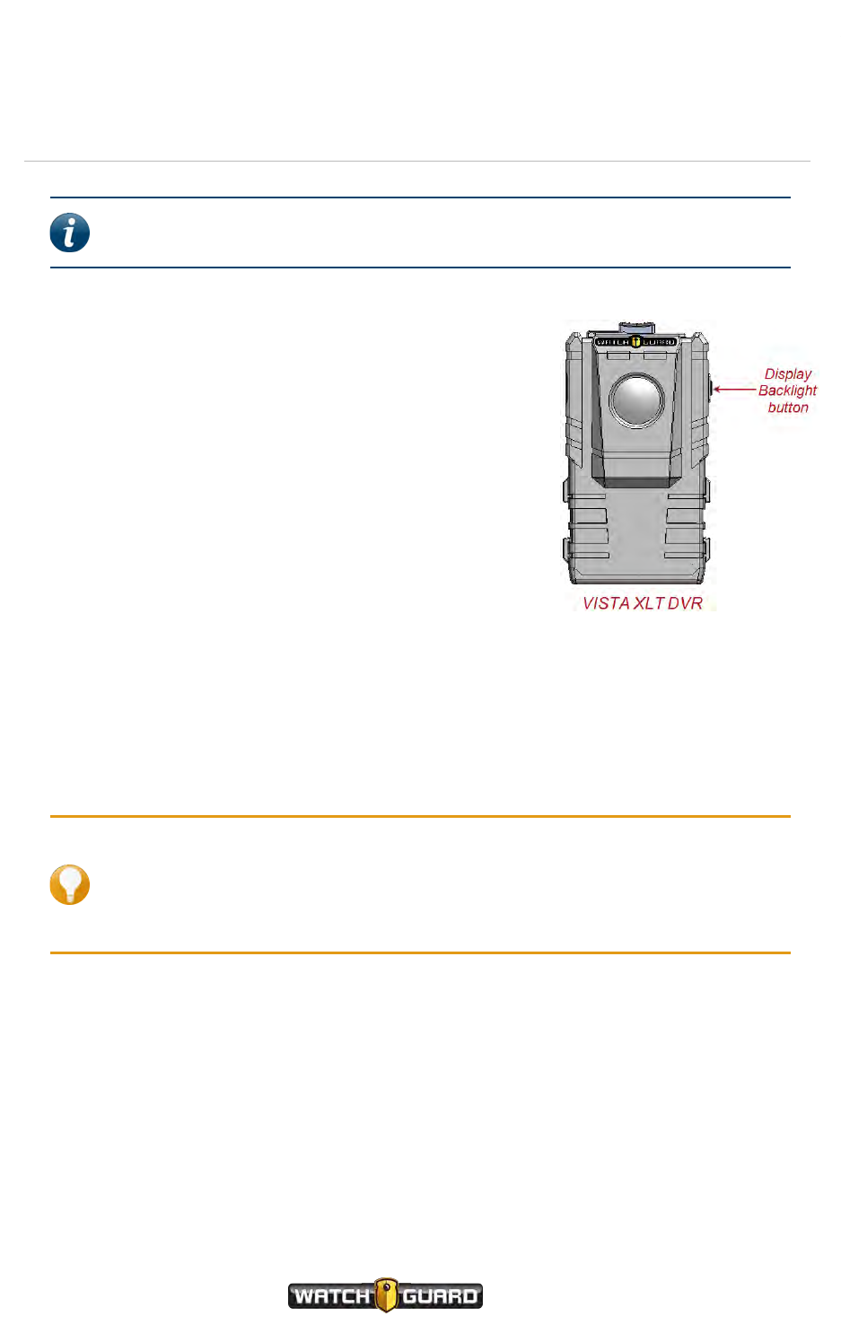
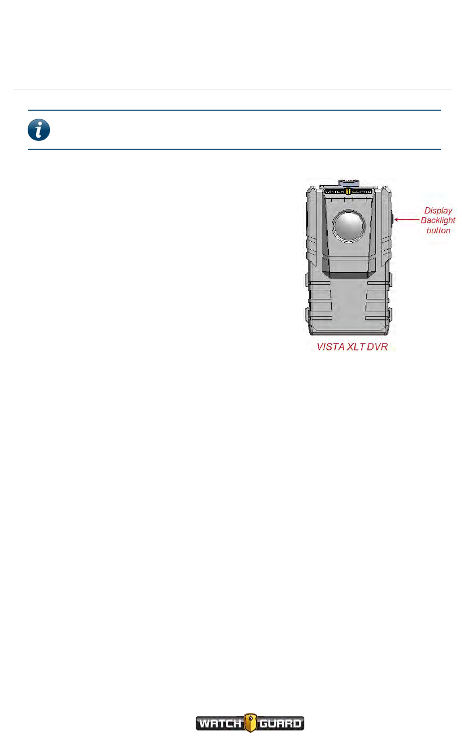
Display Backlight button 54
Display 54
Information Sequence 56
VISTA and VISTA WiFi 56
VISTA XLT 56
Feedback indicators 57
Storage 57
VISTAand VISTA WiFi 58
VISTA XLT 58
Low storage and full storage messages 58
Battery 59
VISTA and VISTAWiFi 59
VISTA XLT 60
LOW BATT/LOW BATTERY message 60
LOW BASE message 60
OVERTEMP message 61
Wi-Fi 61
VISTA WiFi 62
VISTAXLT 62
GPS 62
VISTA WiFi 63
VISTA XLT 63
Quick mounting latch 63
USB Base 64
VISTA Body Camera
WGD00120 Revision
ReviewDraft_111518
vii

Contents
Connections 64
Setting up the VISTA USB Base 64
VISTA Transfer Station 65
LEDs 65
Connections 65
Setting up the VISTA Transfer Station 66
VISTA WiFi Base 66
LEDs 67
Connections 68
Setting up the VISTA WiFi Base 68
VISTABody Camera Special Features 69
Overview 70
Recording special features 70
Battery and storage saving special features 70
Covert Mode 71
Pre-Event Capture 71
Audio 71
Record-After-the-Fact® 72
Generating an RATF event 72
Storage 72
Audio 73
Force Microphone On 73
Sleep Power State 74
Sleep warning period 74
Exiting Sleep state 74
Automatic Off 75
Automatic off warning period 75
Maximum Recorded Event Time 76
Maximum Recorded Event Time warning period 76
Recording Reminder Alert 77
Covert Mode 77
Using VISTAWiFi or VISTA XLT with a Recording Group 79
Overview 80
Recording groups 81
viii
VISTA Body Camera
WGD00120 Revision
ReviewDraft_111518

Contents
Members of the recording group 81
Smart Power Switch 82
4RE DVR 82
VISTA WiFi Base 83
VISTA WiFi and VISTA XLT 84
Other devices in the system 85
Group recordings 85
VISTA WiFi and VISTA XLT behavior during a group recording 86
Appendix A: Using VISTA SmartConnect 89
SmartConnect Overview 90
Activating the VISTA WiFi or VISTA XLT hotspot 91
No cameras found 92
Controlling battery usage 92
Disconnecting SmartConnect 93
Standard disconnect 93
Nonstandard disconnect 93
Connecting to VISTA SmartConnect 94
Connecting VISTA WiFi or VISTA XLT to SmartConnect for the first time 94
Connecting VISTA WiFi or VISTA XLT to SmartConnect after the first time 97
Reviewing VISTAWiFi or VISTA XLT Recorded Events 98
Capturing snapshots 98
Categorizing Recorded Events 99
Live Streaming 101
Covert Mode 102
Starting and Stopping Recorded Events 102
SmartConnect Settings 104
Camera Settings 104
Camera Data 105
Appendix B: Using the Quick Connect Mobile Charger 107
FCC Rules compliance 107
Overview 108
Mobile Charger Parts 108
Mobile Charger base 109
Mobile Charger cable 109
VISTA Body Camera
WGD00120 Revision
ReviewDraft_111518
ix

Contents
Cable connection end 110
12 V cigarette-lighter plug 110
Using the Mobile Charger 111
Appendix C: Upgrading VISTA, VISTAWiFi, and VISTA-Related Devices 113
Upgrading VISTA or VISTA WiFi to Firmware Version 2.2.0 114
Upgrading the VISTA WiFi Base and the Smart Power Switch 115
Upgrading VISTA or VISTA WiFi from a Pre-v2.0.2 Firmware Version 116
Appendix D: VISTA Transfer Station Setup 117
Overview 118
VISTA Transfer Station Hardware 119
Setting up the hardware 119
VISTATransfer Station Configuration 121
Transfer Station Settings 121
Static IP 121
DHCP and Date/Time Settings 122
VISTASettings 122
DHCP 122
Static IP 123
Transfer Station administrative functions 123
Upgrading the Transfer Station software or firmware 123
Changing the login credentials for the Transfer Station configuration page 124
Disabling the configuration page 124
Restarting the Transfer Station 125
Configuring the Transfer Station 125
Index 129
x
VISTA Body Camera
WGD00120 Revision
ReviewDraft_111518

Introduction
Introduction
Welcome to the WatchGuard® VISTA HD Wearable Camera User Guide. This guide is designed
to walk you through the basics of using your VISTA® Body Camera to collect video and audio
evidence.
About this document
The VISTA HD Wearable Camera User Guide covers the basic components and operation of
VISTA, VISTA WiFi, and VISTA XLT™ including:
lDocking, charging, provisioning, and uploading
lAssociating with a recording group (VISTA WiFi and VISTA XLT only)
lWearing the VISTA Body Camera
lPowering on and off
lRecording evidence
lCategorizing events
This guide includes a section on VISTA Body Camera special features:
lPre-event and Record-After-the-Fact® (RATF)
lAutomatic sleep and power off to help you save battery
lMaximum recording length and periodic recording alerts to help you save storage space
lCovert Mode
This guide also includes a section on recording groups and how VISTA WiFi or VISTA XLT and the
WiFi Base work within a local recording group network.
Four appendices to the guide contain:
lInstructions for using the VISTA SmartConnect smartphone app with VISTA WiFi or VISTA XLT
lInstructions for using the VISTA Quick Connect Mobile Charger with extended-capacity VISTA
or VISTA WiFi
lInstructions for special upgrades of the VISTA Body Camera and related devices
lInstructions for setting up the VISTA Transfer Station
Note: This user guide covers the basic use of the VISTA Body Camera. It is not a
comprehensive manual for every possible action or situation you could
experience when using the camera. If you have a question about the VISTA Body
Camera that is not covered in the user guide, contact your WatchGuard
representative.
VISTA Body Camera
WGD00120 Revision
ReviewDraft_111518
11

Introduction
Related documents and information
For subjects related to your WatchGuard system that are not covered by the VISTA HD
Wearable Camera User Guide, see the following documents:
l4RE® In-Car Video User Guide
lEvidence Library 4 Web User Guide
lEvidence Library Express User Guide
l4RE Vehicle Installation Instructions
What's new for version 3
What's new for version 3.0.2:
lSupport for upload from the vehicle using a cellular LTE connection
Version 3.0.2 gives you the option to upload events from a VISTA Body Camera, docked in the
WiFi Base, over a cellular LTE connection to the Evidence Library 4 Web (EL4 Web) upload
server.
WatchGuard supports upload over a cellular connection using the Sierra Wireless® AirLink®
MG90 High Performance Multi-Network Vehicle Router.
The camera must be configured to upload events to EL4 Web from the WiFi Base.
lBattery metrics improvements
lPerformance and security enhancements
lBug fixes
What's new for version 3.0.0:
lSupport for VISTA XLT (page 52)
Version 3 gives you the option to use VISTA XLT as part of your fleet of WatchGuard devices.
VISTA XLT is a two-piece body-worn camera system with an HD camera sensor separate from
the camera DVR. It includes Wi-Fi® and GPS.
lSupport for the VISTAQuick Connect Mobile Charger (page 107)
Version 3 gives you the option to use the VISTA Quick Connect Mobile Charger with extended -
capacity VISTA and VISTA WiFi. The VISTA Quick Connect Mobile Charger is an in-vehicle
charging base that uses a cable to connect to a vehicle's 12 V cigarette-lighter receptacle. It can
charge a worn VISTA Body Camera while the camera is recording, then be disconnected quickly
if needed.
Important! The VISTA Quick Connect Mobile Charger is NOT supported
with standard-capacity VISTA or VISTA XLT.
12
VISTA Body Camera
WGD00120 Revision
ReviewDraft_111518

Using the VISTA Body Camera
Using the VISTA Body Camera
In this section...
lBasic workflow (page 14)
lWearing VISTA and VISTA WiFi (page 15)
lWearing VISTA XLT (page 19)
lPowering the camera on and off (page 24)
lRecording evidence (page 26)
lCategorizing a recorded event (page 29)
lDocking the camera (page 30)
oIn the USB base (page 31)
oIn the VISTA Transfer Station (page 33)
oIn the VISTA WiFi Base (page 34)
oProvisioning (page 35)
oUploading recorded events from storage (page 37)
oUpgrading firmware (page 40)
oCharging the battery (page 42)
oVISTA WiFi and VISTA XLT: Associating with a recording group (page 44)
VISTA Body Camera
WGD00120 Revision
ReviewDraft_111518
13
Using the VISTA Body Camera
Overview
You use the VISTA Body Camera as a DVR (digital video recorder) to capture, process, and store
video and audio evidence. You connect the camera with your Evidence Library software to
provision it as well as to upload its video for evidence management.
WatchGuard offers three types of VISTA Body Camera:
lVISTA: All-in-one HD body camera that does not include Wi-Fi® or GPS
lVISTA WiFi: All-in-one HD body camera that includes Wi-Fi and GPS
lVISTA XLT: Two-piece body camera system with an HD camera sensor separate from the
camera DVR; it includes Wi-Fi® and GPS
If your agency is using VISTA WiFi or VISTA XLT, you can pair the camera with a VISTA WiFi
Base that is associated with a 4RE DVR. The devices together form a recording group.
Note: If you are not sure whether your equipment has the Wi-Fi feature,
contact your WatchGuard representative.
Basic workflow
The following steps make up a basic workflow for using the VISTA Body Camera during your
shift:
Note: This workflow assumes the VISTA Body Camera battery has been fully
charged before the camera is checked out to start the shift.
1. With the VISTA Body Camera in the dock, provision the camera and then check it out using
your Evidence Library software. (page 35)
2. Undock the camera.
3. (VISTA XLT only) Connect the sensor head and cable to the main body of the camera, if not
already done. (page 19)
4. (VISTA WiFi and VISTA XLT only) Dock the camera in the VISTA WiFi Base (WiFi Base) to pair it
with the base and associate it with the local recording group. (page 44)
5. (VISTA WiFi and VISTA XLT only) Undock the camera after it has paired with the WiFi Base.
6. Attach VISTA or VISTA WiFi (page 15) or VISTA XLT (page 19) securely to your clothing.
7. Start and stop recorded events. (page 26)
8. Categorize recorded events. (page 29)
9. Power the camera off or on, as needed. (page 24)
10. Dock the camera to upload recorded events (page 37) and charge its battery (page 42).
14
VISTA Body Camera
WGD00120 Revision
ReviewDraft_111518
Wearing VISTA and VISTAWiFi
Wearing VISTA and VISTAWiFi
VISTA and VISTA WiFi have four main mounting options. The quick mounting latch on VISTA
and VISTA WiFi attaches to any of the mounts:
lRotatable shirt clip (below)
lDuty belt clip (below)
lLocking chest mount (page 16)
lMOLLE vest loop mount (page 17)
Wear VISTA or VISTA WiFi on your clothing where it is most comfortable, convenient, and
secure for you. Make sure that the lens is not obstructed and that it is aimed at the horizon.
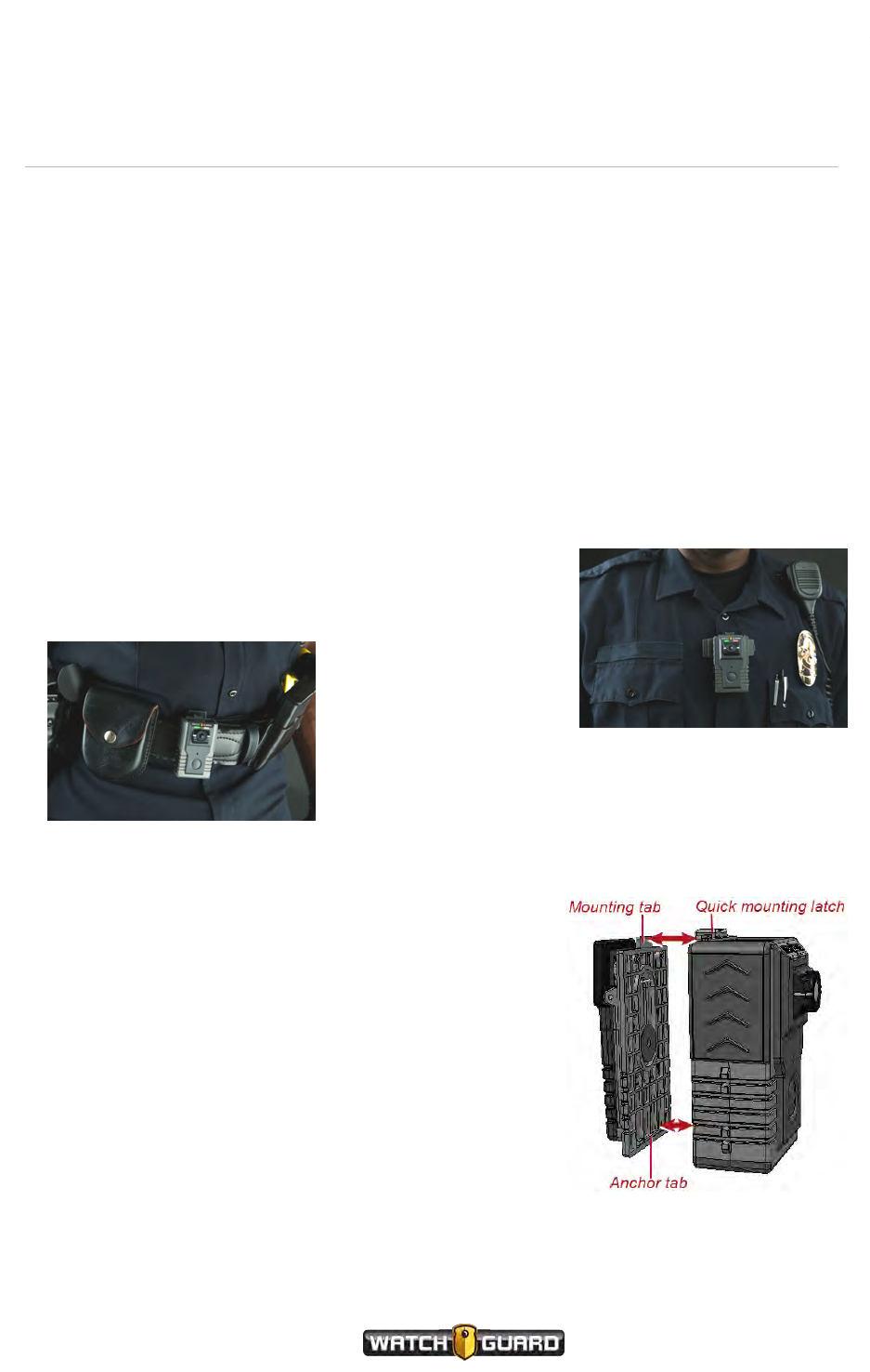
Using the rotatable shirt clip and duty belt clip
The rotatable clip mount uses a heavy-duty alligator clip that
rotates and slides to make it more convenient for you to secure
the camera.
The belt clip mount
uses an alligator clip
with a hook at the bottom to securely clip the camera
to your duty belt.
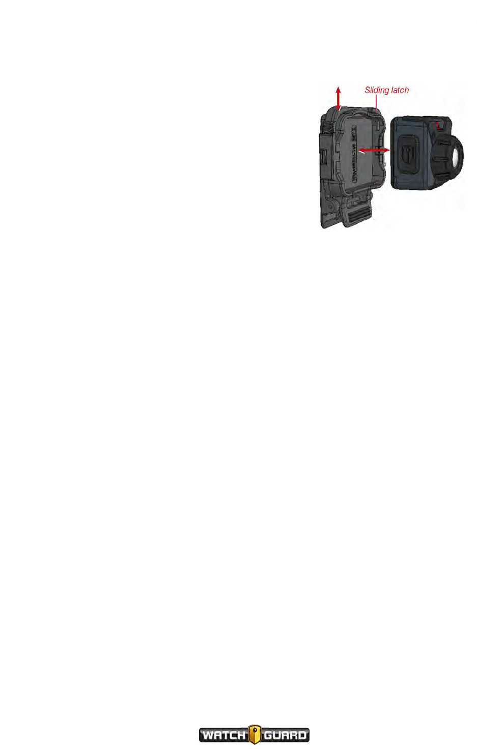
Both clips connect to the camera the same way:
1. Match the anchor tab on the back of the clip with the
slot on the back of the camera.
2. Match the mounting tab on the clip with the quick
mounting latch on the camera, then slide the latch
over the tab.
3. Attach the clip to your clothing or your belt where you
want to wear the camera.
VISTA Body Camera
WGD00120 Revision
ReviewDraft_111518
15
Using the VISTA Body Camera
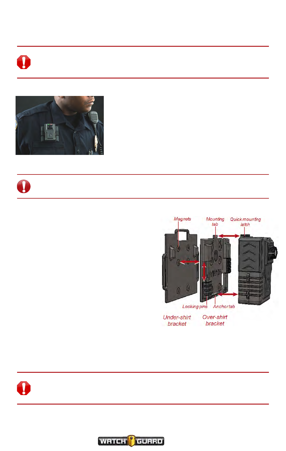
Using the locking chest mount
Warning! The chest mount uses magnets to hold the camera in place. Do not
wear the chest mount near sensitive medical equipment or implants such as
pacemakers or other magnetically programmable medical devices.
The chest mount uses magnets and locking pins to
secure the mount to your clothing. When you wear
the chest mount, one bracket goes under your shirt,
the other goes over your shirt.
Important! Because of the strength of the magnets, separating the brackets
requires effort. Realigning the brackets causes them to snap together forcefully.
To use the chest mount:
1. Separate the under-shirt bracket from the
over-shirt bracket.
2. Match the anchor tab on the over-shirt
bracket with the slot on the back of the
camera.
3. Match the mounting tab on the over-shirt
bracket with the quick mounting latch on the
camera, then slide the latch over the tab.
4. Place the under-shirt bracket under your
shirt where you want to wear the camera.
5. Place the over-shirt bracket, with the camera
attached, against the under-shirt bracket,
with your shirt between them.
The magnets on both brackets line up
automatically, securing the mount to your
shirt.
6. To lock the mount in place, slide both of the locking pins up into their safety housings.
Warning! The chest mount uses magnets to hold the camera in place. Do not
wear the chest mount near sensitive medical equipment or implants such as
pacemakers or other magnetically programmable medical devices.
16
VISTA Body Camera
WGD00120 Revision
ReviewDraft_111518
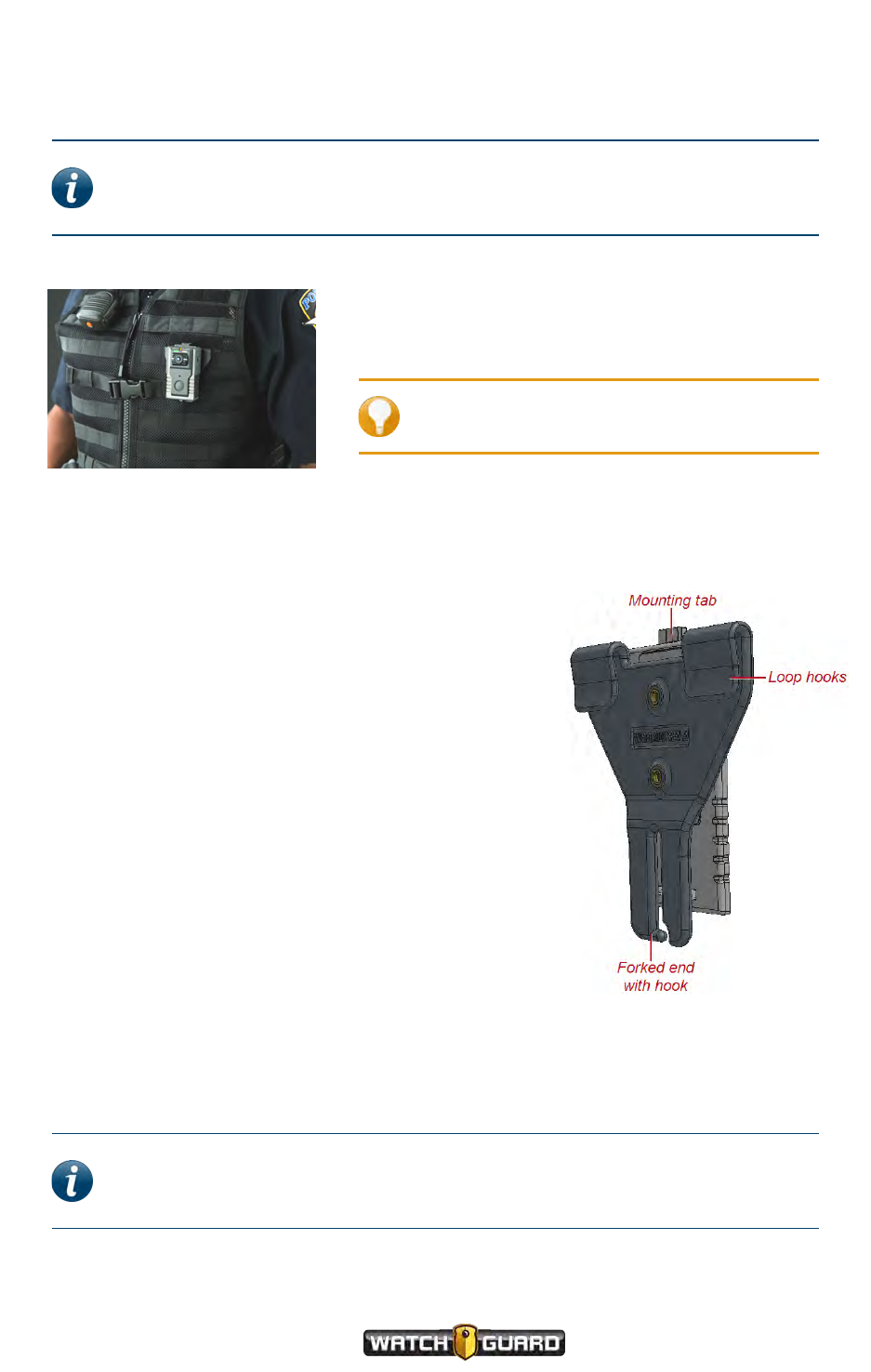
Using the MOLLE vest loop mount
Using the MOLLE vest loop mount
Note: Some of the earliest versions of the VISTA Body Camera do not connect to
the MOLLE vest mount. Please consult with your WatchGuard representative for
more information.
The MOLLE vest mount uses hooks to anchor VISTA or
VISTA WiFi over two rows of loops on the MOLLE vest.
Tip: Install the mount on the vest before
you connect the camera to the mount.
To use the MOLLE vest mount:
1. Determine which two rows of loops on the MOLLE vest
you want to use to mount the VISTA Body Camera.
2. On the lower of the two rows, slide the forked end
down over the sewn seam between two loops until the
hook is engaged below the seam.
You may need to slightly twist the mount to help the
hook slide over the seam.
3. Slightly fold the fabric between the two rows so that
the upper loop hooks engage two loops on the upper
row of loops.
4. Slide the upper loop hooks down over the two loops,
straightening the fabric between the rows, to fully
seat the mount.
The forked end should be fully engaged with the seam
on the lower row of loops. The hooks should be fully
engaged with two loops on the upper row of loops.
5. Match the anchor tab on the bottom of the outward-
facing plate of the MOLLE vest mount with the bottom
slot on the back of VISTA.
6. Match the mounting tab on the top of the mount with the quick mounting latch on VISTA,
then slide the latch over the tab.
Note: The camera connects to the MOLLE vest mount in the same way it
connects to the shirt or belt clip. For more information, see Using the rotatable
shirt clip and duty belt clip on page 15.
VISTA Body Camera
WGD00120 Revision
ReviewDraft_111518
17

Using the VISTA Body Camera
Other VISTAand VISTA WiFi mounts
Other mount options include:
lVELCRO® plate mount: Works with externally-worn vests with VELCRO surfaces
lKlick Fast mount: Works with UK-style Klick Fast receivers
lTripod mount: Works on standard mounts with 1/4″-20 threads
lRAM® mount: Includes a 1-inch ball for RAM accessories
Contact your WatchGuard representative for information.
18
VISTA Body Camera
WGD00120 Revision
ReviewDraft_111518

Wearing VISTA XLT
Wearing VISTA XLT
Each VISTA XLT uses two mounts: one for the DVR and one for the camera sensor.
These mounts are available for the DVR:
lBelt clip (page 20)
lBelt holster (page 20)
This mount is available for the head-mounted camera sensor:
lGlasses mount (page 21)
The glasses mount has been designed to work with Oakley Flak Jacket® glasses.
These mounts are available for the body-mounted camera sensor:
lMagnetic mount (page 22)
lShirt clip (page 23)
The DVR connects to the camera sensor using a cable. Various cables and strain-relief clips are
available.
Recommended mounting order for VISTA XLT system
To wear VISTA XLT:
1. Disconnect the cable from the VISTA XLT DVR and camera sensor.
2. Mount the DVR and attach it to your belt.
3. Mount the camera sensor and attach it to your glasses or clothing as appropriate.
4. Connect the camera sensor end of the cable to the camera sensor, then route the cable
through your clothing toward the DVR as appropriate.
Note: The DVR end of the cable is marked with DVR.
5. Connect the DVR end of the cable to the DVR.
Wear the VISTA XLT DVR and camera sensor where they are most comfortable, convenient,
and secure for you. Make sure that the lens is not obstructed and that it is aimed at the horizon.
Tip: For specific recommendations on wearing VISTA XLT, review the
WatchGuard Online Training Course for VISTA XLT. For access to the training
course, contact WatchGuard Customer Service.
VISTA Body Camera
WGD00120 Revision
ReviewDraft_111518
19
Using the VISTA Body Camera
Wearing the DVR
These mounts are available for the DVR:
lBelt clip
lBelt holster
Using the DVRbelt clip
Tip: Remove VISTA XLT from the belt clip before docking the camera.
To use the belt clip:
1. Match the anchor tab on the back of the clip with the slot
on the back of the VISTA XLT DVR.
2. Match the mounting tab on the clip with the quick
mounting latch on the DVR, then slide the latch over the
tab.
3. Attach the clip to your duty belt where you want to wear
the DVR.
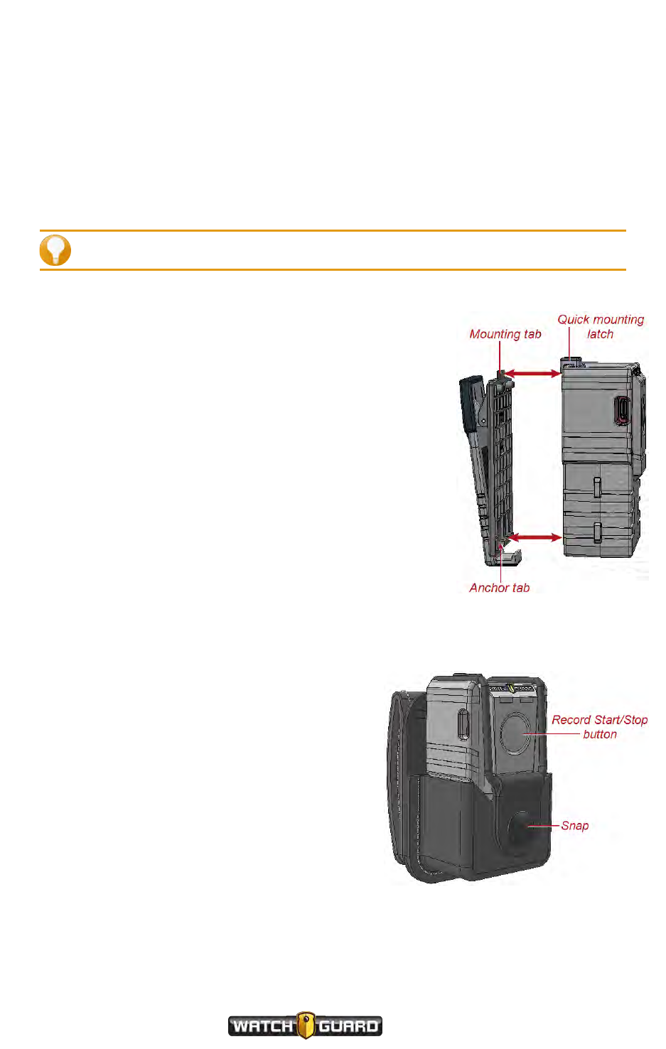
Using the DVR belt holster
To use the holster:
1. Unsnap the empty holster.
2. Slide the VISTA XLT DVR into the holster with
the Record Start/Stop button facing out.
3. Snap the holster closed, stretching the elastic
over the top of the DVR.
4. Thread the holster onto your duty belt where
you want to wear the DVR.
20
VISTA Body Camera
WGD00120 Revision
ReviewDraft_111518
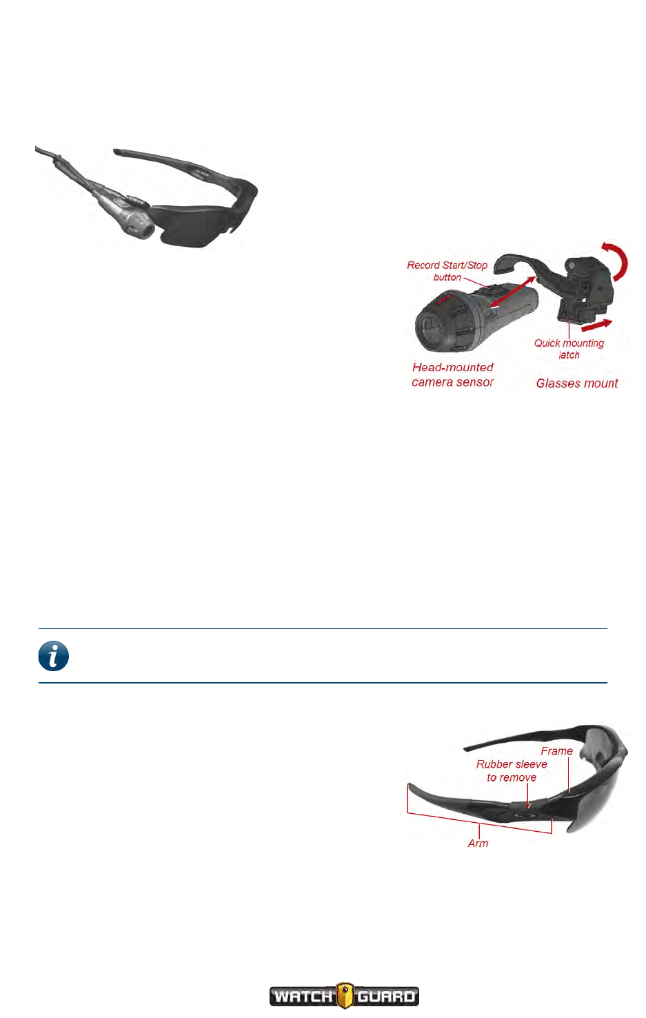
Wearing the head-mounted camera sensor
Wearing the head-mounted camera sensor
The glasses mount is available for the head-mounted camera sensor.
The glasses mount has been designed to work
with Oakley Flak Jacket® glasses, available
through WatchGuard.
Using the glasses mount
To use the glasses mount for the head-mounted camera
sensor:
1. If you have not already done so, disconnect the
cable from your VISTA XLT DVR and camera sensor.
2. On the Oakley glasses provided by WatchGuard,
remove the rubber sleeve from the right arm of the
frames.
For instructions, see Preparing your Oakley glasses below.
3. Snap the glasses mount into the groove on the head-mounted camera sensor.
4. Slide the quick mounting latch backwards and open the hinged part of the mount.
5. Fit the mount over the raised ovals on the bare arm of the Oakley glasses.
6. Close the hinged part of the mount then slide the quick mounting latch forward.
Preparing your Oakley glasses
Note: Oakley glasses are designed for the arms to be removed and the rubber
sleeves to be replaced.
To prepare your Oakley glasses for mounting:
1. Grasp the right arm of the glasses near the frame
and, with gentle force, twist the arm to snap it out
of the frame.
2. Slide the rubber sleeve off of the arm and set it
aside.
3. Snap the arm back into the glasses frame.
VISTA Body Camera
WGD00120 Revision
ReviewDraft_111518
21
Using the VISTA Body Camera
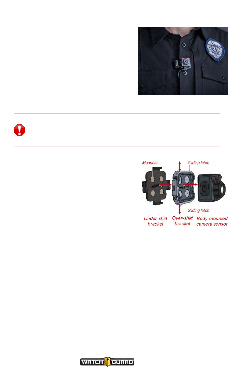
Wearing the body-mounted
camera sensor
These mounts are available for the body-mounted
camera sensor:
lMagnetic mount
lShirt clip
Using the magnetic mount
Warning! The magnetic mount uses magnets to hold the body-mounted
camera sensor in place. Do not wear the mount near sensitive medical
equipment or implants such as pacemakers or other magnetically programmable
medical devices.
To use the magnetic mount for the body-mounted
camera sensor:
1. If you have not already done so, disconnect the
cable from your VISTA XLT DVR and camera
sensor.
2. Separate the under-shirt bracket from the over-
shirt bracket.
Separating the brackets requires some effort.
3. On the over-shirt bracket, slide out both latches.
4. Snap the body-mounted camera sensor into the
over-shirt bracket, then push in the sliding
latches.
5. Place the under-shirt bracket under your shirt where you want to wear the camera sensor.
6. Place the over-shirt bracket, with the camera sensor attached, against the under-shirt bracket,
with your shirt between them, making sure the camera sensor LED is at the top.
22
VISTA Body Camera
WGD00120 Revision
ReviewDraft_111518
Using the shirt clip
Using the shirt clip
To use the shirt clip for the body-mounted camera sensor:
1. If you have not already done so, disconnect the cable
from your VISTA XLT DVR and camera sensor.
2. Slide out the latch on the clip.
3. Snap the body-mounted camera sensor into the clip (in
any orientation), then slide in the latch.
4. Attach the shirt clip to your clothing where you want to
wear the camera sensor, making sure the camera
sensor LED is at the top.
VISTA Body Camera
WGD00120 Revision
ReviewDraft_111518
23
Using the VISTA Body Camera
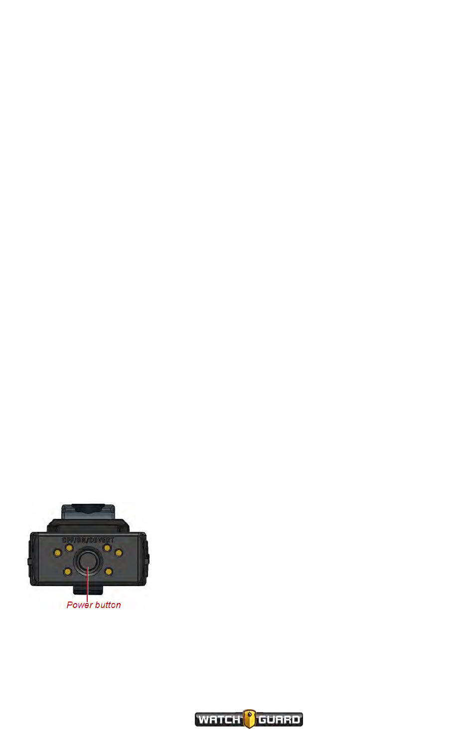
Powering On and Off
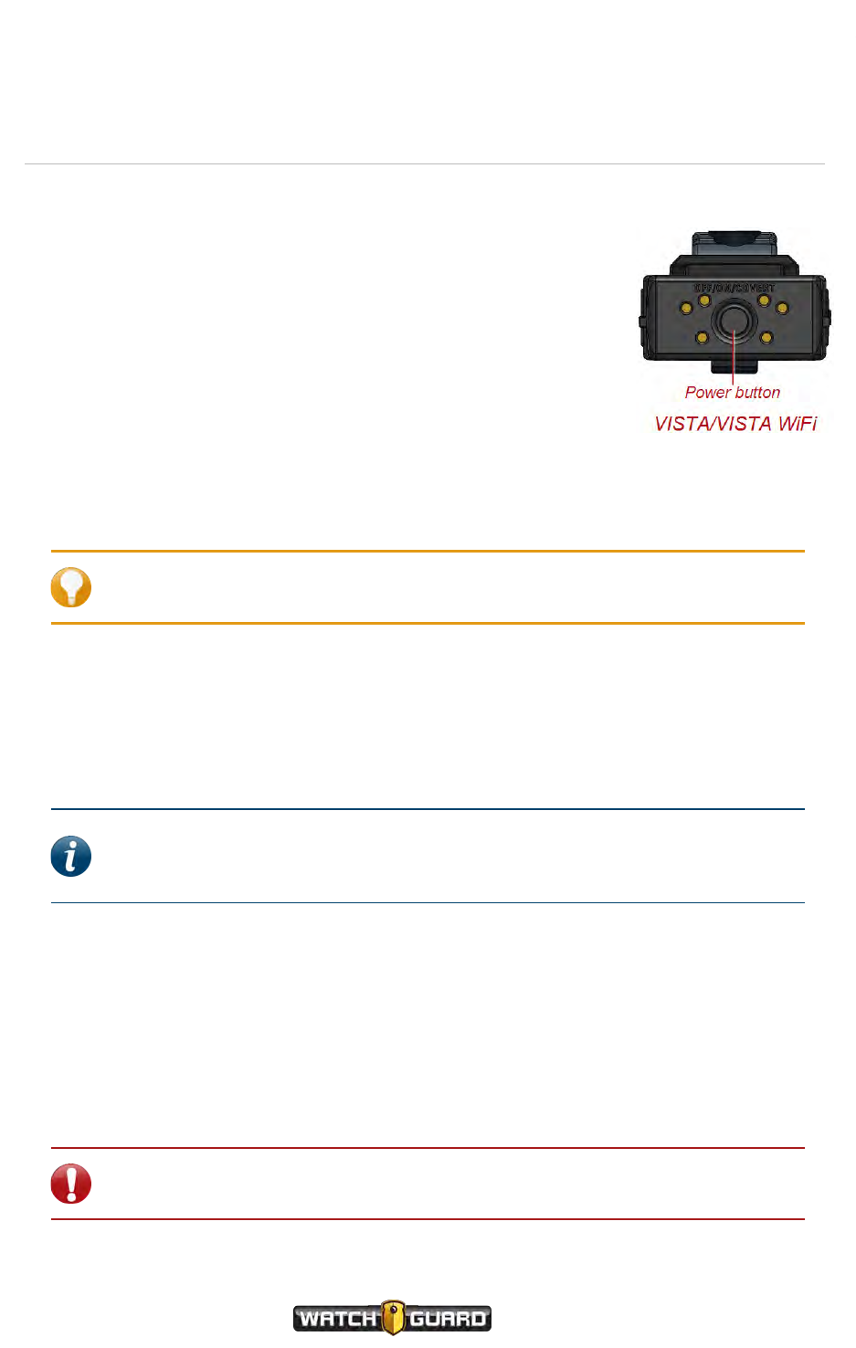
You use the Power button to power the VISTA Body Camera on and
off. The Power button is on the bottom of VISTA, VISTA WiFi, and the
VISTA XLT DVR.
Powering on
To power the camera on:
nWith the power off, press and release the Power button.
The camera goes through its booting and information sequences.
When it is ready to use, the display shows the number of events in
storage and the green LED lights steadily. Ascending tones sound (depending on your
notification selections).
Tip: (VISTA XLT) Press the Display Backlight button to advance through the
information sequence screens.
(VISTA XLT) If the camera sensor is not connected to the DVR, the display reads Camera
UNPLUGGED. When you connect the camera sensor to the DVR, the display reads
CONNECTING, then shows the number of events in storage and the green LEDs light steadily.
Powering off
Note: The VISTA Body Camera can be configured to power off automatically if it
is left idle (no movement and/or button presses) for a period of time. For more
information, see Automatic Off on page 75.
To power the camera off:
nWith the power on, press and release the Power button two times within 5 seconds.
After you press and release the Power button the first time, the display reads OFF? 2X (VISTA
and VISTA WiFi) or OFF? Press Again (VISTA XLT) to confirm that you want to power the
camera off.
Once you press the Power button the second time, the display reads SHUTTING DOWN and
the green LED turns off. Descending tones sound (depending on your notification selections).
Important! If you do not press the Power button a second time within 5
seconds, the display clears, and you need to start the power off sequence again.
24
VISTA Body Camera
WGD00120 Revision
ReviewDraft_111518

Forcing power off
Forcing power off
In the rare case where the VISTA Body Camera stops responding to commands (or if
WatchGuard Technical Services instructs you to), you can force the camera to power off.
Warning! Avoid forcing the VISTA Body Camera to power off, if at all possible.
Forcing the camera's power off can, in rare cases, result in data corruption.
To force the VISTA Body Camera to power off:
nPress and hold the Power button until the camera powers off, about 15 seconds.
Note: If you have forced the camera's power off, WatchGuard recommends that
you dock it in a USBBase as soon as it is feasible. Docking the camera in a USB
Base allows VISTA to repair itself.
VISTA Body Camera
WGD00120 Revision
ReviewDraft_111518
25
Using the VISTA Body Camera
Starting and Stopping a Recorded Event
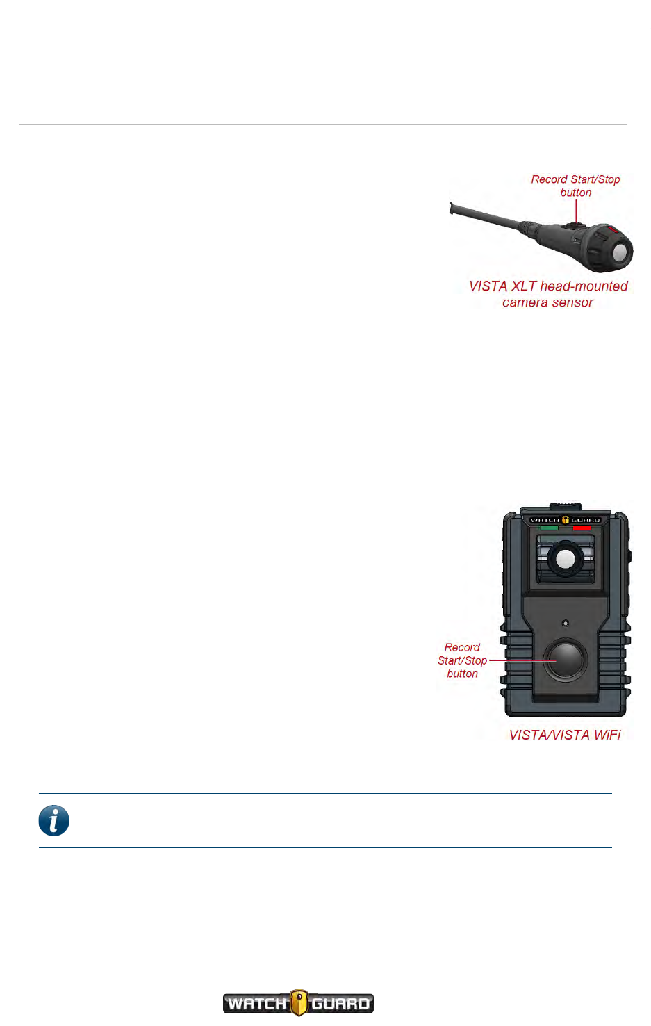
Typically, you use a Record Start/Stop button to start or stop a
recorded event on the VISTA Body Camera. The Record
Start/Stop button is on the front of VISTA and VISTA WiFi.
VISTA XLT has two Record Start/Stop buttons, one on the
front of the DVR and one on each camera sensor.
If your VISTA WiFi or VISTA XLT is a member of a
recording group, the camera can start or stop a recorded event
automatically when alerted by another group member that the
other group member has started or stopped an event. For more
information on recording groups, see Using VISTAWiFi or VISTA
XLT with a Recording Group on page 79.
If your VISTA WiFi is connected to the VISTA SmartConnect smartphone app, you
can start or stop a recorded event using SmartConnect. For more information on using the
smartphone app, see Starting and Stopping Recorded Events on page 102.
Starting a recorded event manually
To manually start a recorded event on the VISTA Body Camera:
nPress a Record Start/Stop button.
(VISTA/VISTA WiFi) The display shows the REC icon and the
recording length, then begins to blink the REC icon. The red
LED lights steadily and ascending tones sound with a vibration
(depending on your alert notification selections).
(VISTA XLT) The display reads RECORDING, then begins to
blink the dot in the REC icon and show the recording length.
The red LEDs light steadily and ascending tones sound with a
vibration (depending on your alert notification selections).
As the recorded event continues, the display shows the current
recorded event length increasing every second and the storage
indicators updating as needed.
Note: A VISTA WiFi or VISTA XLT that has automatically started an event
behaves in the same way.
26
VISTA Body Camera
WGD00120 Revision
ReviewDraft_111518
Stopping a recorded event manually
Stopping a recorded event manually
Note: The VISTA Body Camera can be configured to NOT allow manual event
stop. If you cannot manually stop the camera, when you press a Record
Start/Stop button, two low tones sound with a vibration (depending on your
alert notification selections) and the display reads IGNORED for 3 seconds.
To manually stop a recorded event on the VISTA Body Camera:
nPress a Record Start/Stop button.
Important! You may need to press a Record Start/Stop button a second time
within 5 seconds to confirm the event stop, depending on your configuration.
The REC icon turns off on the display and the red LED turns off. Descending tones sound with a
vibration (depending on your alert notification selections).
After a recorded event has stopped, if event categorization is required as part of the camera's
configuration, the event categorization sequence starts. For instructions how to categorize a
recorded event, see Categorizing a Recorded Event on page 29.
Note: A VISTA WiFi or VISTA XLT that has automatically stopped an event
behaves in the same way.
The VISTA Body Camera can be configured to stop a recorded event automatically after a period
of time. For more information, see Maximum Recorded Event Time on page 76.
Tip: Even if VISTA WiFi or VISTA XLT is NOT configured to require an event-stop
confirmation (second press of a Record Start/Stop button within 5 seconds),
you need to confirm an event stop in the following scenario:
VISTA WiFi or VISTA XLT automatically starts an event because a member of the
local recording group reports that it started a recorded event. You immediately
(within 10 seconds) press a Record Start/Stop button to STOP the recorded
event because you do not want VISTA WiFi or VISTA XLT to record it. The camera
requests that you press a Record Start/Stop button again to confirm that you
want to STOP the recorded event. If you do not press the button a second time
within 5 seconds, VISTA WiFi or VISTA XLT continues to record the event.
VISTA Body Camera
WGD00120 Revision
ReviewDraft_111518
27
Using the VISTA Body Camera
Muting the Audio During a Recorded Event
Note: The ability to mute a VISTA Body Camera during a recorded event is set up
as part of a configuration in WatchGuard Evidence Library software.
You can use the Display Backlight button on the VISTA Body
Camera to mute the audio during a recorded event. The
Display Backlight button is on the right side as you look at
the front of the VISTA, VISTA WiFi, or VISTA XLT DVR.
If the camera is configured to allow muting, when you press
and hold down the Display Backlight button during an
event, the camera mutes the event audio. As long as you
continue to hold the Display Backlight button, the audio is
muted. When you release the button, the event audio
continues normally.
Muting audio
To mute audio during a recorded event:
1. Press and hold down the Display Backlight button.
2. Continue to hold down the Display Backlight button as long as you want the event audio to
remain muted.
The display reads MUTED while you hold down the Display Backlight button.
The camera's audio unmutes when you release the Display Backlight button.
Tip: You cannot mute the audio while you are categorizing a recorded event.
Selecting a category requires that you hold down the same button (Display
Backlight) you hold down for muting. Once you have finished categorizing, you
can again mute the audio. For information on categorizing a recorded event on
the VISTA Body Camera, see Categorizing a Recorded Event on page 29.
28
VISTA Body Camera
WGD00120 Revision
ReviewDraft_111518
Categorizing a Recorded Event
Categorizing a Recorded Event
Note: Event categorization is set up as part of a configuration in WatchGuard
Evidence Library software.
You use the Display Backlight button on the VISTA Body
Camera to select a category to apply to a recorded event. The
Display Backlight button is on the right side as you look at
the front of the VISTA, VISTA WiFi, or VISTA XLT DVR.
If the camera is configured to require categorization, when
you stop an event, the display immediately prompts you to
select an event category.
If your VISTA WiFi or VISTA XLT is a member of a
recording group, the camera can automatically accept an
event category from the 4RE DVR group member as its own
category. However, any category selected directly on VISTA
WiFi or VISTA XLT overrides the 4RE category. For more
information on recording groups, see Using VISTAWiFi or
VISTA XLT with a Recording Group on page 79.
If your VISTA WiFi or VISTA XLT is connected to the
VISTA SmartConnect smartphone app, you can
categorize an event using SmartConnect. Any category selected on SmartConnect overrides a
4RE category. If you categorize an event on both the VISTA WiFi camera and the smartphone
app, the last selected category, regardless of the device, will be applied to the event. For more
information on using the smartphone app, see Categorizing Recorded Events on page 99.
Categorizing a recorded event on the camera
To categorize a recorded event:
1. Stop the event manually or allow VISTA WiFi or VISTA XLT to stop the event automatically.
The display shows the Category prompt.
2. Press and release the Display Backlight button as many times as needed to move through
the list of available event categories, one at a time.
3. Press and hold the Display Backlight button for at least 2 seconds when the event category
you want to select shows on the display.
The display reads SAVED and shows which category you selected. One long tone sounds with
a vibration (depending on your alert notification selections).
If another recorded event starts (manually or automatically) while the camera is in the middle
of the event categorization sequence, the camera aborts the sequence and starts the new
event. You will be able to categorize the recorded event later in your Evidence Library software,
if necessary.
VISTA Body Camera
WGD00120 Revision
ReviewDraft_111518
29

Using the VISTA Body Camera
Docking the VISTA Body Camera
WatchGuard offers three different bases where you can dock your VISTA Body Camera:
lUSB Base (page 31)
lVISTA Transfer Station (page 33)
lVISTA WiFi Base (page 34)
Docking the camera allows you to perform the following tasks:
lUpload recorded events from storage (page 37)
lUpgrade firmware (page 40)
lCharge the battery (page 42)
Use the USB Base or the Transfer Station inside your agency when fully charging the battery.
Use the WiFi Base in the vehicle for incidental charging during your shift. Charging in a vehicle
base can impact the vehicle battery and can slow down significantly in warmer temperatures.
Important! Battery charging shuts down at ambient temperatures
greater than 35 degrees C (95 degrees F).
lProvision the camera (USB Base and Transfer Station only) (page 35)
lDefine a Record-After-the-Fact®(RATF) event (USB Base only) (page 39)
lRequest a state capture for troubleshooting (USB Base only)
lAssociate with a recording group that can include a 4RE DVR and other VISTA WiFi or VISTA XLT
cameras (WiFi Base only) (page 44)
The VISTA Body Camera needs to interact with Evidence Library software to be customized for
your agency. For that interaction to take place, the camera must be docked in a VISTA USB
Base or Transfer Station connected to your Evidence Library software.
You can dock any VISTA Body Camera in any of the three bases.
30
VISTA Body Camera
WGD00120 Revision
ReviewDraft_111518
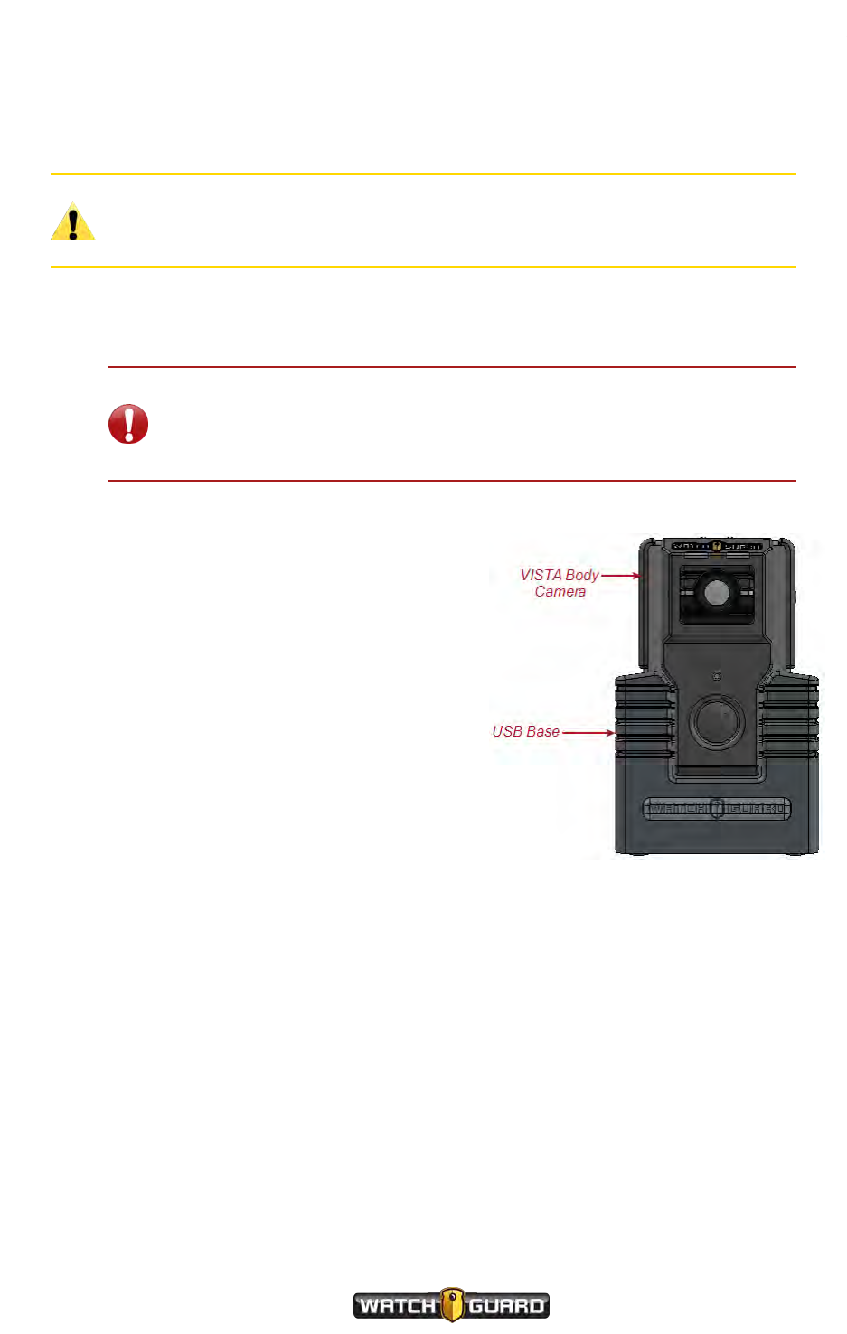
Docking the VISTA Body Camera in a USB Base
Docking the VISTA Body Camera in a USB Base
When you dock the VISTA Body Camera in a USB Base connected to Evidence Library software:
Caution: To prevent possible damage to some computers, connect the USB
Base to the computer through the approved USB hub (Sabrent 7-Port USB 2.0
Hub, WatchGuard part number WGP02364).
lThe camera's battery begins to charge, if needed
lVISTA's time and date synchronize with the Evidence Library system, if needed (VISTA only)
Important! VISTA (no Wi-Fi® and GPS) sets its internal date and time
from the Evidence Library software's computer. If the computer's date
and time is set incorrectly, VISTA's will be set incorrectly, and your video
evidence will be marked with the incorrect date and time.
lThe camera's firmware upgrades, if a firmware
upgrade has been staged on the camera
lThe camera communicates to the Evidence
Library software that it has recorded events to
upload
lRecorded events are uploaded to the Evidence
Library software
lThe Evidence Library software sends
commands and/or requests to the camera as
applicable:
oMark any imported recorded events as
import confirmed
oUpdate the configuration
oStage a firmware upgrade
oGenerate an RATF event
oGenerate a state capture
When you undock the camera from the USB Base, it processes the Evidence Library software
commands and requests before it is ready for normal operation.
VISTA Body Camera
WGD00120 Revision
ReviewDraft_111518
31

Using the VISTA Body Camera
Undocking the camera from the USB Base
Evidence Library software commands and requests are only applied when the camera is
undocked from a USB Base. When you undock the camera, it processes the commands and
requests in the following order, as applicable:
1. Performs a state capture.
The display reads STATE CAPTURE.
2. Updates the configuration.
The display reads CONFIG. The configuration update alert sounds when the update is
finished.
3. Generates an RATF event.
The display reads CREATING RATF.
Note: After the RATF event has been generated, the camera starts the
event categorization sequence for the RATF event if it is configured to
require event categorization. For instructions how to categorize an
event, see Categorizing a Recorded Event on page 29.
4. Unprotects the recorded events confirmed as imported.
This makes the storage space available to be reused as needed.
5. Stages the firmware upgrade to perform the next time the camera is docked.
Once all the commands and requests are processed, VISTA is ready for normal operation.
For more information about the USB Base, see USB Base on page 64.
32
VISTA Body Camera
WGD00120 Revision
ReviewDraft_111518
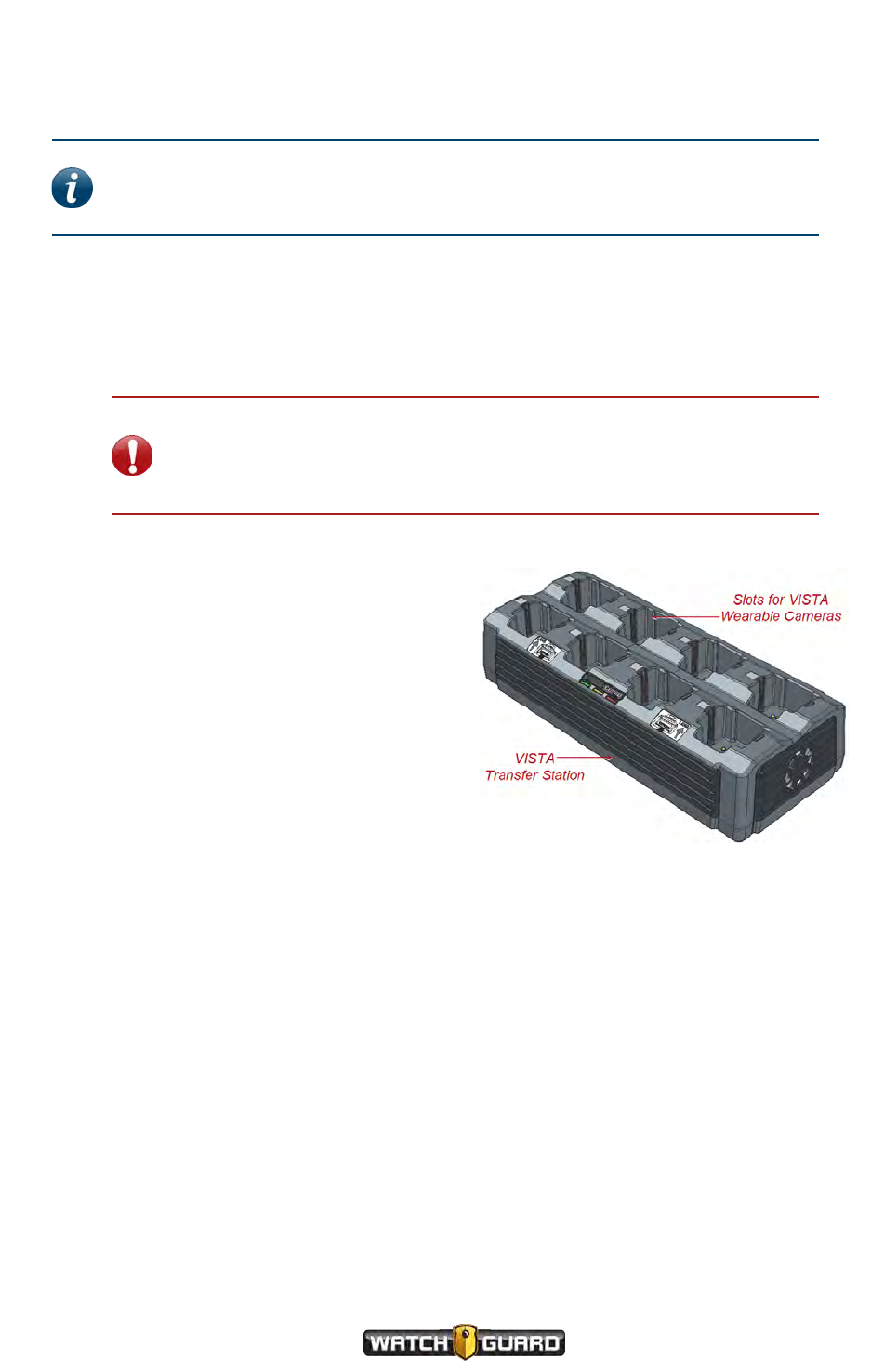
Docking the VISTA Body Camera in a VISTA Transfer Station
Docking the VISTA Body Camera in a VISTA Transfer Station
Note: The VISTA Transfer Station must be set up and configured to be used with
your Evidence Library software. For instructions how to set up the Transfer
Station, see Appendix D: VISTA Transfer Station Setup on page 117.
When you dock the VISTA Body Camera in a Transfer Station connected to Evidence Library
software:
lThe camera's battery begins to charge, if needed
lVISTA's time and date synchronize with the Evidence Library system, if needed (VISTA only)
Important! VISTA (no Wi-Fi® and GPS) sets its internal date and time
from the Evidence Library software's computer. If the computer's date
and time is set incorrectly, VISTA's will be set incorrectly, and your video
evidence will be marked with the incorrect date and time.
lThe camera's firmware upgrades, if a
firmware upgrade has been staged on the
camera
lThe camera communicates to the Evidence
Library software that it has recorded events
to upload
lRecorded events are uploaded to the
Evidence Library software
lEvidence Library software sends commands
and/or requests to the camera as applicable:
oMark any imported recorded events as
import confirmed
The events confirmed as imported are
immediately unprotected. This makes
the storage space available to be reused
as needed.
oUpdate the configuration
If the configuration is manually pushed to the camera (through the Evidence Library
checkout process), the configuration is updated immediately.
If the configuration is automatically pushed to the camera, the configuration is
updated after the camera is undocked.
oStage a firmware upgrade
The firmware upgrade is staged on the camera immediately, and then is applied the next
time the camera is docked.
When you undock the camera from the Transfer Station, it is ready for normal operation.
For more information about the Transfer Station, see VISTA Transfer Station on page 65.
VISTA Body Camera
WGD00120 Revision
ReviewDraft_111518
33
Using the VISTA Body Camera
Docking the VISTABody Camera in a WiFi Base
Note: Not all VISTA Body Cameras or VISTA bases have the Wi-Fi® feature. For
more information, contact your WatchGuard representative.
When you dock the VISTA Body Camera in a VISTA WiFi Base:
lThe camera's battery begins to charge, if needed
lThe camera's firmware upgrades, if a firmware upgrade
has been staged on the camera
lVISTA WiFi or VISTA XLT pairs with the WiFi Base; when
it does, it becomes associated with the local recording
group (VISTA WiFi and VISTA XLT only)
When the camera becomes associated with the local
recording group, it is disassociated from any other
recording group.
When you dock the VISTA Body Camera in a VISTAWiFi Base
that is connected to an Evidence Library 4 Web upload server:
Note: WatchGuard recommends that you use version 4.2 (or later) of EL4 Web
for the best experience.
lThe camera communicates to EL4 Web that it has recorded events to upload
The camera must be configured to upload events directly to EL4 Web from the WiFi Base.
lRecorded events are uploaded to EL4 Web
lEL4 Web sends commands and/or requests to the camera as applicable:
oMark any imported recorded events as import confirmed
The events confirmed as imported are immediately unprotected. This makes the storage
space available to be reused as needed.
oStage a firmware upgrade
The firmware upgrade is staged on the camera immediately, and then is applied the next
time the camera is docked.
When you undock the camera from the WiFi Base, it is ready for normal operation.
For more information about...
The WiFi Base, see VISTA WiFi Base on page 66.
Recording groups, see Using VISTAWiFi or VISTA XLT with a Recording Group on page 79.
Upgrading the WiFi Base, see Upgrading the VISTA WiFi Base and the Smart Power Switch on
page 115.
34
VISTA Body Camera
WGD00120 Revision
ReviewDraft_111518
Provisioning the camera
Provisioning the camera
Tip: Before using the VISTA Body Camera for the first time, fully charge and
provision it.
You provision your VISTA Body Camera while it is docked in a USB Base or VISTA Transfer
Station. When you provision the camera, you use your WatchGuard Evidence Library software
to assign a configuration and an officer name.
Depending on how your agency assigns its cameras, you may need to provision and check out
the camera each time you use it (for example, from a pool of cameras) or only rarely as its
configuration needs to be updated (for example, if a camera has been assigned to you long-
term).
To provision the VISTA Body Camera:
1. Dock the camera in the USB Base or Transfer Station connected to your Evidence Library
software.
2. Using Evidence Library software, create and/or assign a configuration and an officer to the
docked camera.
For instructions how to assign a configuration and officer to the camera, see your Evidence
Library software documentation.
As a configuration is applied to the camera, the display reads CONFIG. The configuration
update alert sounds when the update is finished.
VISTA Body Camera configuration
You can only create a VISTA Body Camera configuration in your Evidence Library software.
Note: For instructions how to create and set up a configuration for the VISTA
Body Camera, see your Evidence Library software documentation.
Some of the configuration properties you can set up for the VISTA Body Camera in your
Evidence Library software include:
lAgency or department name
lTime zone where the agency or department is located
lOfficer name and badge ID
lDevice ID
lEvent tags including a list of possible event categories (page 29)
lOfficer preferences for indicators, including (page 57)
oAlert preference (none, tone, vibration, or tone and vibration together)
oLED brightness
oTone volume
VISTA Body Camera
WGD00120 Revision
ReviewDraft_111518
35

Using the VISTA Body Camera
lVISTA WiFi and VISTA XLT behaviors, including
oRecording group interactions (page 79)
oAllowing connection to the VISTA SmartConnect smartphone app
lNetwork preferences, including
oAllowing the camera to upload to Evidence Library 4 Web (EL4 Web) when docked in a
VISTA WiFi Base (EL4 Web only)
oMaximum wireless upload time (EL4 Web only)
lRecording preferences, including
oVideo quality and frame rate
oEnabling Record-After-the-Fact®(RATF) (page 72)
oForcing microphone on all the time (page 73)
oAllowing audio muting (page 28)
oDisabling VISTA audio completely
oEnabling pre-event capture (page 71)
oEnabling split events
oRequiring confirmation of recorded event stop
lPower- and storage-saving preferences, including
oAllowing sleep (page 74)
oAllowing automatic power off (page 75)
oEnabling maximum recorded event time (page 76)
oEnabling recording reminder alerts (page 77)
36
VISTA Body Camera
WGD00120 Revision
ReviewDraft_111518
Uploading events
Uploading events
You can upload recorded events from your VISTA Body Camera while it is docked in any of the
three bases:
lUSB Base
You can upload recorded events automatically or manually from a camera in a USB Base,
depending on the settings in your Evidence Library software. While the camera is uploading
from a USB Base, you can monitor its upload progress in the Evidence Library software.
lVISTA Transfer Station
Events upload automatically from a camera in the VISTA Transfer Station.
lVISTA WiFi Base
Events upload from a camera (typically VISTA WiFi or VISTA XLT) in the WiFi Base, only if the
WiFi Base is connected to an Evidence Library 4 Web (EL4 Web) upload server. The events
upload automatically.
With the VISTA Body Camera version 3.0.2, events can upload from a camera in the WiFi Base
over a cellular LTE connection to the EL4 Web upload server.
Note: WatchGuard supports upload over a cellular connection using the
Sierra Wireless® AirLink® MG90 High Performance Multi-Network
Vehicle Router.
The camera must be configured to upload events to EL4 Web from the WiFi Base.
Important! Critical events always upload first.
You use your WatchGuard Evidence Library software to manage all aspects of the upload and
import.
To upload recorded events from the VISTA Body Camera:
1. Dock the camera in a base or Transfer Station connected to your Evidence Library software.
The Evidence Library software automatically detects that the camera is docked in a USB
Base or Transfer Station and that it has events to upload. The events begin to upload
automatically if applicable.
EL4 Web automatically detects that the camera is docked in a WiFi Base and that it has
events to upload. The events begin to upload automatically if applicable.
2. Follow any prompts in the Evidence Library software to upload video from the camera and
import it to evidence storage.
The camera must remain docked during the upload process.
VISTA Body Camera
WGD00120 Revision
ReviewDraft_111518
37
Using the VISTA Body Camera
VISTA and VISTAWiFi
Note: While VISTA or VISTA WiFi is uploading from the USB Base, you can
monitor its upload progress in your Evidence Library software.
While VISTA or VISTA WiFi is uploading from the VISTA WiFi Base or Transfer Station:
lThe display reads XX of YY, where XX is the current event being uploaded and YY is the total
number of events to upload, and the bars on the Storage Used meter disappear
lThe red LED fast blinks during the entire upload process
When the camera is finished uploading critical events:
lThe display scrolls CRITICALCOMPLETE one time then returns to XX of YY
lThe red LED continues to fast blink during the entire upload process
lOne long tone sounds
When the camera is finished uploading all events:
lThe display scrolls UPLOADCOMPLETE
lTwo long tones sound
VISTA XLT
Note: While VISTA XLT is uploading from the USB Base, you can monitor its
upload progress in your Evidence Library software.
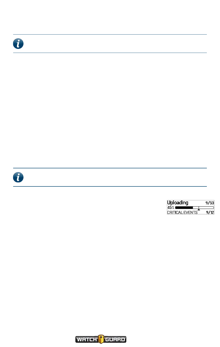
While VISTA XLT is uploading from the VISTA WiFi Base or Transfer
Station:
lThe display:
oFirst line reads Uploading XX/YY where XX is the current
event being uploaded and YY is the total number of events to
upload
oSecond line shows the percentage of saved storage already uploaded next to a progress bar
representing the total number of events to upload; the progress bar includes a Critical
Complete indicator
oThird line reads CRITICALEVENTS XX/YY, where XX is the current critical event being
uploaded and YY is the total number of critical events to upload, or NON-
CRITICALEVENTS
lThe red LED fast blinks during the entire upload process
38
VISTA Body Camera
WGD00120 Revision
ReviewDraft_111518

Record-After-the-Fact® events
When the camera is finished uploading critical events:
lThe third line of the display reads CRITICALCOMPLETE for 5
seconds, then reads NON-CRITICALEVENTS for the duration of
the upload
lOne long tone sounds
When the camera is finished uploading all events:
lThe display reads Uploading YY EVENTS COMPLETE for 5
seconds, where YY is the total number of events uploaded
lTwo long tones sound
Record-After-the-Fact®events
If the VISTA Body Camera is configured with Record-After-the-Fact (RATF) enabled and it is
docked in a USB Base, you can use the Evidence Library software to define and request an RATF
event from the camera. (An RATF event usually consists of video that was not originally part of
a recorded event.) The camera generates the RATF event after you undock it, then uploads the
RATF event the next time you dock for upload.
Clearing video out of camera storage
Once the VISTA Body Camera has successfully uploaded its recorded events to evidence storage
using Evidence Library software, the camera no longer protects that storage space. It can be
used for future recorded events.
For more information about...
How to import video from the VISTA Body Camera to your evidence storage, see your Evidence
Library software documentation.
The VISTA Body Camera and RATF events, see Record-After-the-Fact® on page 72.
Recorded events, see Video, Audio, and Subtitle Evidence on page 46.
VISTA Body Camera
WGD00120 Revision
ReviewDraft_111518
39

Using the VISTA Body Camera
Upgrading firmware
You can push new firmware to the VISTA Body Camera while it is docked in any of the bases:
lUSB Base
You can push an upgrade automatically or manually when it is docked in a USB Base, depending
on the settings in your Evidence Library software.
lVISTA Transfer Station
You can push an upgrade automatically when it is docked in a VISTA Transfer Station.
lVISTA WiFi Base
You can push an upgrade to the VISTA Body Camera (typically VISTA WiFi or VISTA XLT) when
it is docked in a VISTA WiFi Base, ONLYIF the WiFi Base is connected to an Evidence Library 4
Web (EL4 Web) upload server. The upgrade is pushed automatically.
When an upgrade is pushed to the camera, the firmware is first staged on the camera, then
the next time the camera is docked, the upgrade is applied.
To upgrade the VISTA Body Camera's firmware:
1. Dock the camera in a base or Transfer Station connected to your Evidence Library software.
The Evidence Library software automatically detects that the camera is docked and that its
firmware needs to be upgraded.
2. Using Evidence Library software, make sure the new firmware is pushed to the camera.
Note: Evidence Library software can be set up to push new firmware
manually or automatically. For instructions, see your Evidence Library
software documentation.
The new firmware is staged on the camera.
3. The next time you dock the camera, the upgrade is applied.
The camera MUST remain docked while the upgrade is being applied. The camera cannot
perform any other function, including uploading video, while it is upgrading its firmware.
Warning! DONOT REMOVE the camera from the dock while its new firmware is
being applied. Removing the camera from the dock during the upgrade can cause
the camera to stop functioning.
40
VISTA Body Camera
WGD00120 Revision
ReviewDraft_111518
VISTA and VISTAWiFi
VISTA and VISTAWiFi
Note: If a VISTA or VISTA WiFi is docked in a USBor WiFi Base while the upgrade
is being staged on the camera, the display does not show the staging process.
While the upgrade is being staged on a VISTA or VISTA WiFi in a Transfer Station, the
display:
lStorage Used meter fills with bars and Storage Percentage increases
l8-character area scrolls DOWNLOADING
When the upgrade has finished staging, the Storage Used meter is full, the Storage
Percentage shows 100%, and the 8-character area scrolls DOWNLOADCOMPLETE for
about 5 seconds.
The next time you dock the camera in the USB Base, WiFi Base, or the Transfer Station, the
upgrade is applied. While the upgrade is being applied,UPDATING DO NOTINTERRUPT
scrolls on the display.
Warning! DONOT REMOVE the camera from the dock while its new firmware is
being applied. Removing the camera from the dock during the upgrade can cause
the camera to stop functioning.
When the upgrade has finished applying, the camera sounds the camera ready alert
(depending on your alert notification selections).
VISTAXLT
Note: If the VISTA XLT is docked in a USBor WiFi Base while the upgrade is being
staged on the camera, the display does not show the staging process.
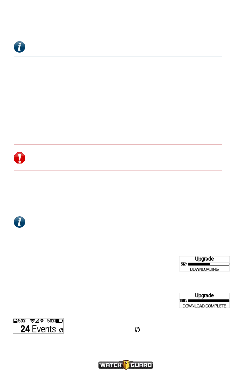
While the upgrade is being staged on a VISTA XLT in a Transfer Station, the display:
lFirst line reads Upgrade
lSecond line shows the percentage of the upgrade already
downloaded next to a progress bar
lThird line reads DOWNLOADING
When the upgrade has finished staging on the camera, the
percentage downloaded and progress bar show 100%, and the third line
reads DOWNLOADCOMPLETE for 5 seconds.
If VISTA XLT is undocked and not
recording, and has an upgrade staged on the camera, the
Upgrade Staged icon ( ) appears in the lower right corner of
the display.
VISTA Body Camera
WGD00120 Revision
ReviewDraft_111518
41
Using the VISTA Body Camera
The next time you dock the camera in the USB Base, WiFi Base, or the Transfer Station, the
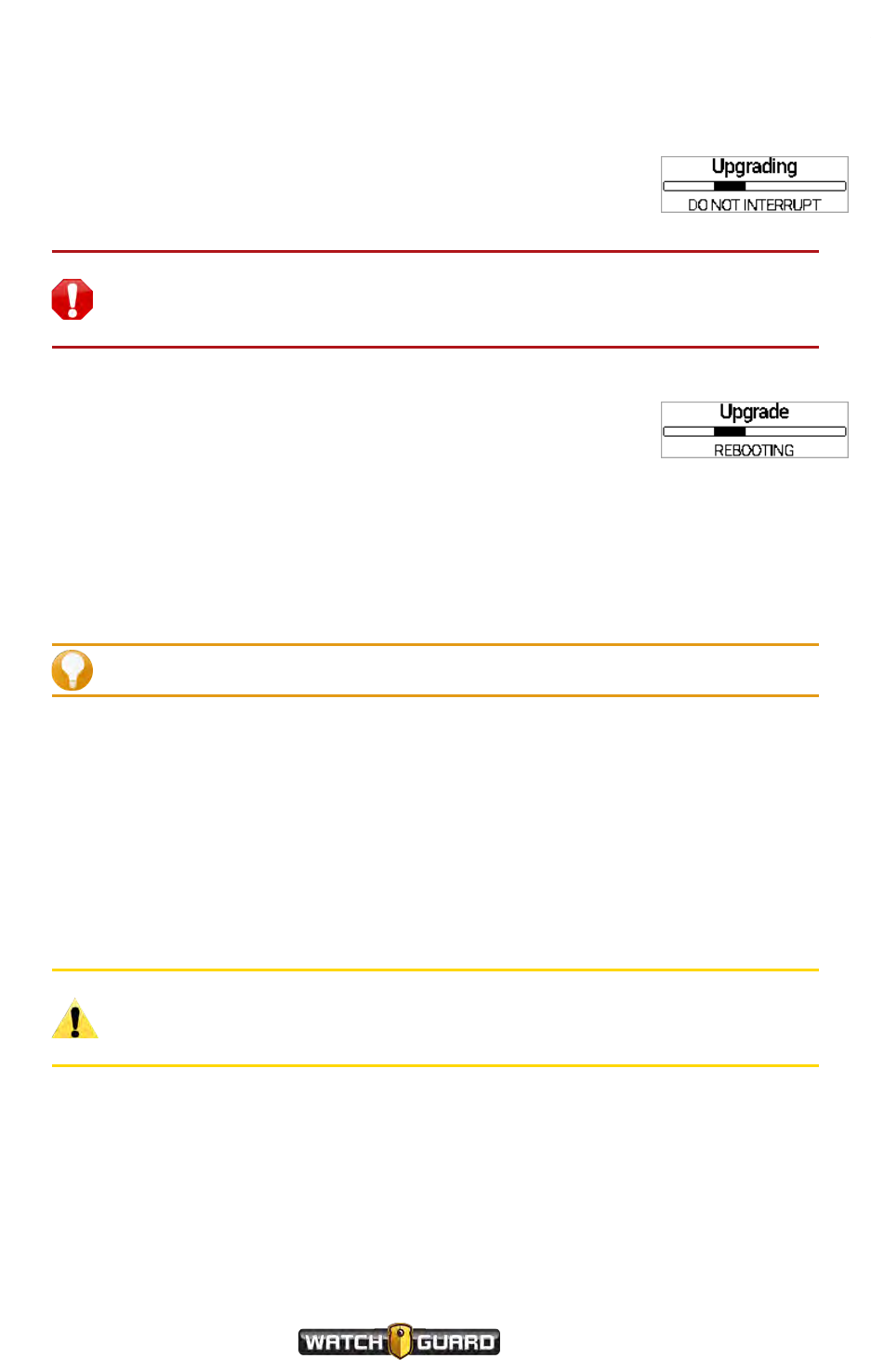
upgrade is applied. While the upgrade is being applied, the display:
lFirst line reads Upgrading
lSecond line shows a status bar
lThird line reads DONOT INTERRUPT
Warning! DONOT REMOVE the camera from the dock while its new
firmware is being applied. Removing the camera from the dock during the
upgrade can cause the camera to stop functioning.
When the upgrade has finished applying, the camera reboots. The
third line of the display reads REBOOTING.
For more information about...
Upgrading the VISTA WiFi Base and the Smart Power Switch, see Upgrading the VISTA WiFi
Base and the Smart Power Switch on page 115.
Charging the battery
Tip: Before using the camera for the first time, fully charge and provision it.
The VISTA Body Camera charges any time it is docked, if it needs to charge. VISTA and VISTA
WiFi's batteries can fully charge in 3 to 5 hours. VISTA XLT's battery can fully charge in about 7
hours.
To fully charge the camera:
nDock the camera in either the USB Base or the VISTA Transfer Station inside your agency.
The camera can charge in a USB Base connected to the USBport on a computer, depending on
the amount of power provided by the USB port. The camera charges significantly faster when
docked in a USB Base that is plugged into an electrical outlet or in a Transfer Station.
Caution: To prevent possible damage to some computers, connect the USB
Base to the computer through the approved USB hub (Sabrent 7-Port USB 2.0
Hub, WatchGuard part number WGP02364).
WatchGuard recommends that you use the USB Base or the Transfer Station inside your
agency when fully charging the VISTA Body Camera's battery. Charging in a vehicle base can
impact the vehicle battery and can slow down significantly in warmer temperatures. For the
best battery life and fastest charging times, you should charge the VISTA Body Camera in a
cooler environment.
42
VISTA Body Camera
WGD00120 Revision
ReviewDraft_111518
VISTA and VISTAWiFi
Important! Battery charging shuts down at ambient temperatures greater
than 35 degrees C (95 degrees F).
VISTA and VISTAWiFi
While VISTAand VISTA WiFi are charging:
lThe display alternates between CHARGING and the Device ID, and the Battery
Charge icon animates
lThe green LED blinks
When the cameras are fully charged:
lThe display scrolls CHARGE COMPLETE once, then continuously shows the Device
ID, and the Battery Charge icon shows five bars
lThe green LED lights steadily
lTwo tones sound
VISTAXLT
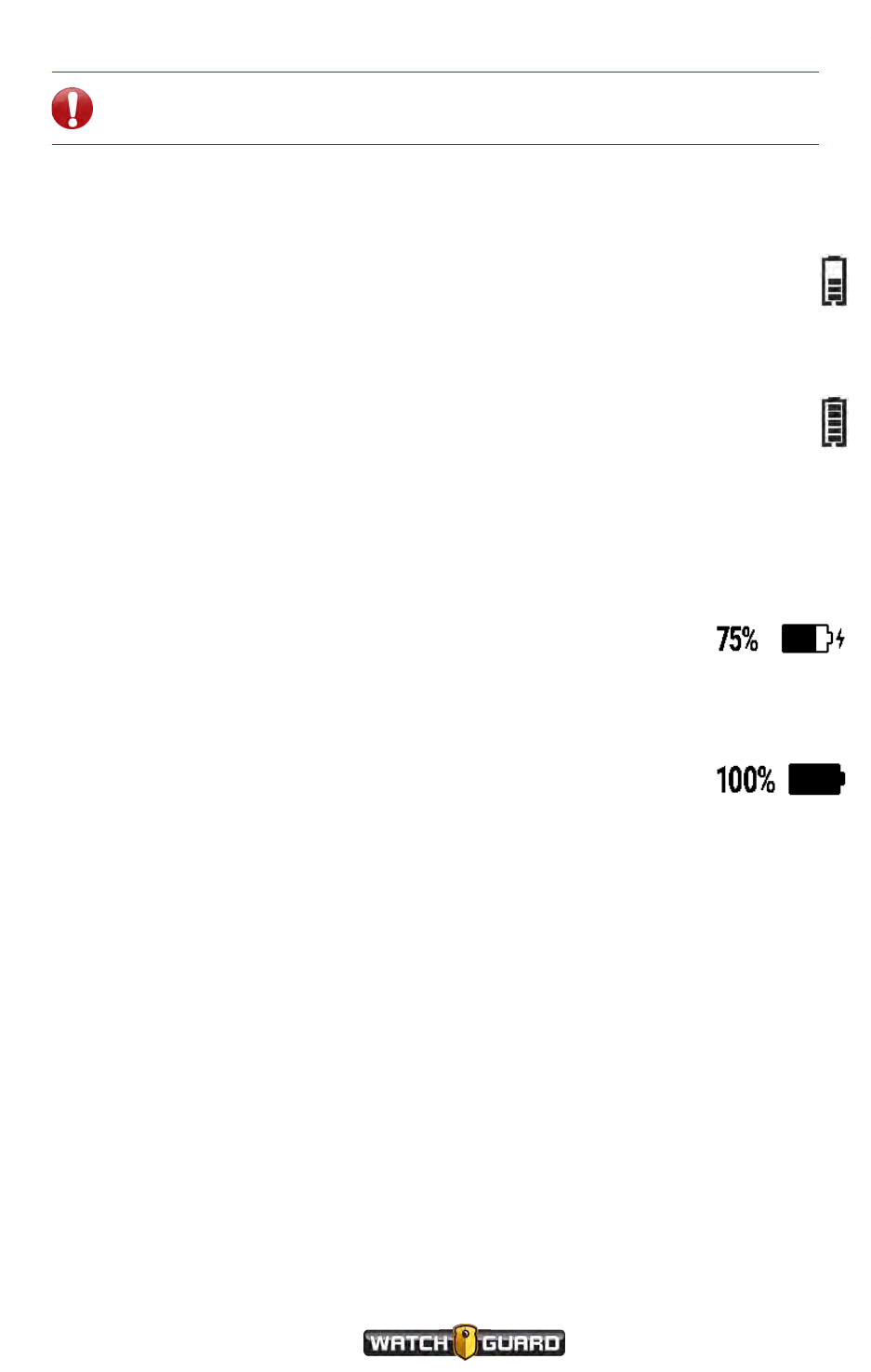
As VISTA XLT charges:
lThe display shows the Battery Charge percentage growing, the
Battery Charge icon filling, and a lightning bolt next to the icon, blinking
lThe green LED on the DVR blinks
When the camera is fully charged:
lThe display shows 100% and a fully-filled Battery Charge icon for a few
seconds, then alternates between the Officer Name and the Device
ID
lThe green LED on the DVR lights steadily
lTwo tones sound
For more information about VISTA Body Camera batteries, see Battery on page 59.
VISTA Body Camera
WGD00120 Revision
ReviewDraft_111518
43

Using the VISTA Body Camera
VISTA WiFi and VISTAXLT: Associating with a recording
group
When you dock VISTA WiFi or VISTA XLT in a VISTA WiFi Base, the camera pairs with the WiFi
Base. This pairing allows the camera to associate with the local recording group that includes
the WiFi Base. The recording group can also include other VISTA WiFi or VISTA XLT cameras and
the local 4RE DVR. A recording group is typically linked to a vehicle.
Note: You can pair more than one camera with the same WiFi Base.
When VISTA WiFi or VISTA XLT is associated with a recording group, it can participate in group
recordings. A group recording is multiple devices collaborating to start and stop their recorded
events together. When a group recording is uploaded, each device's event is linked to the other
group members' events.
To associate VISTA WiFi or VISTA XLT with a recording group:
nDock the camera in a VISTA WiFi Base that is connected to a local recording group.
The WiFi Base left LED blinks green multiple times when the camera and base have successfully
paired. When the camera is undocked, the display shows Wi-Fi Signal Strength bars (VISTA
WiFi) or a partially filled triangle (VISTA XLT) when the camera is paired with and in range of the
WiFi Base.
Once the camera is paired with the base, it is associated with the local recording group (and is
disassociated from any other recording group).
For more information on recording groups, see Using VISTAWiFi or VISTA XLT with a Recording
Group on page 79.
44
VISTA Body Camera
WGD00120 Revision
ReviewDraft_111518

About the VISTA Body Camera
About the VISTA Body Camera
In this section...
lVideo, audio, and subtitle evidence (page 46)
lCamera components
oVISTA and VISTA WiFi (page 48)
oVISTA XLT (page 52)
lThe bases
oUSB Base (page 64)
oVISTA Transfer Station (page 65)
oVISTA WiFi Base (page 66)
VISTA Body Camera
WGD00120 Revision
ReviewDraft_111518
45

About the VISTA Body Camera
Overview
The VISTA Body Camera:
lCaptures, processes, and stores video and audio evidence (below)
lFunctions as a camera and DVR (digital video recorder) combination
oVISTA (page 48)
oVISTA WiFi (page 48)
oVISTA XLT (page 52)
lCan be docked in any of three bases (USB, Transfer Station, WiFi) for charging and uploading,
and two of the three (USB, Transfer Station) for provisioning
oUSB Base (page 64)
oVISTA Transfer Station (page 65)
oVISTA WiFi Base (page 66)
lCan be paired with a VISTA WiFi Base for charging, uploading, and associating with a recording
group (VISTA WiFi and VISTA XLT only) (page 66)
Video, Audio, and Subtitle Evidence
The VISTA Body Camera works as a DVR and camera combination to collect evidence in the
form of recorded events. A recorded event is a unique, protected segment of recorded:
lVideo (page 47)
lAudio (page 47)
lSubtitles (page 47)
When you press a Record Start/Stop button to start and then stop a recording, the VISTA
Body Camera protects the video/audio segment between the two button presses as a recorded
event.
If your VISTA WiFi or VISTA XLT is a member of a recording group, the camera can
also start or stop a recorded event automatically when alerted by another group member that
the other group member has started or stopped an event. VISTA WiFi and VISTA XLT protect
the segment between the automatic start and stop in the same way they protect the segment
between the manual button presses. Both protected segments are recorded events.
Note: If you are not sure whether your equipment includes the Wi-Fi® feature,
contact your WatchGuard representative.
Depending on the configuration applied to the camera, it may be capturing video all the time or
only during a recorded event. If the camera is capturing video all the time (Record-After-the-
46
VISTA Body Camera
WGD00120 Revision
ReviewDraft_111518

Video
Fact®(RATF) is enabled), only the protected segment (between the manual or automatic start
and stop) is considered a recorded event.
Tip: If the camera is configured with RATF enabled, you may be able to use your
Evidence Library software to send a manual request to the camera to retrieve an
RATF event: video that was not originally part of a recorded event. For more
information about retrieving an RATF event from the VISTA Body Camera, see
your Evidence Library software user guide.
If the camera is configured to enable pre-event video, a recorded event also includes that pre-
event time.
Normally, only recorded events are uploaded to your Evidence Library software.
Video
The VISTA Body Camera records one stream of video and compresses it using h.264 high-profile
compression. Depending on the configuration applied to the camera, the video quality can be:
lHigh definition (HD), 720p, at a frame rate of 5, 10, 15, or 30 frames per second
or
lStandard definition (SD), 480p, at a frame rate of 5, 10, 15, or 30 frames per second
Audio
The VISTA Body Camera records CD quality audio with minimal distortion and wind noise.
Depending on the configuration applied to the camera, it can:
lContinuously record audio
or
lOnly record audio during recorded events
Subtitles
Subtitles are the text information that can be overlaid on the video. The VISTA Body Camera
includes the following subtitles:
lOfficer name
lDate and time
lDevice ID
lMicrophone on or off
lGPS location (VISTA WiFi or VISTA XLT only)
Tip: The subtitles are always included with the video and audio in a recorded
event, but using your Evidence Library software, you can turn them off or on.
VISTA Body Camera
WGD00120 Revision
ReviewDraft_111518
47
About the VISTA Body Camera
For more information about...
The RATF special feature, see Record-After-the-Fact® on page 72.
Pre-event video, see Pre-Event Capture on page 71.
Provisioning thecamera with a configuration, see Provisioning the camera on page 35.
Importing VISTA Body Camera recorded events to Evidence Library software, see Uploading
events on page 37.
Recording groups, see Using VISTAWiFi or VISTA XLT with a Recording Group on page 79.
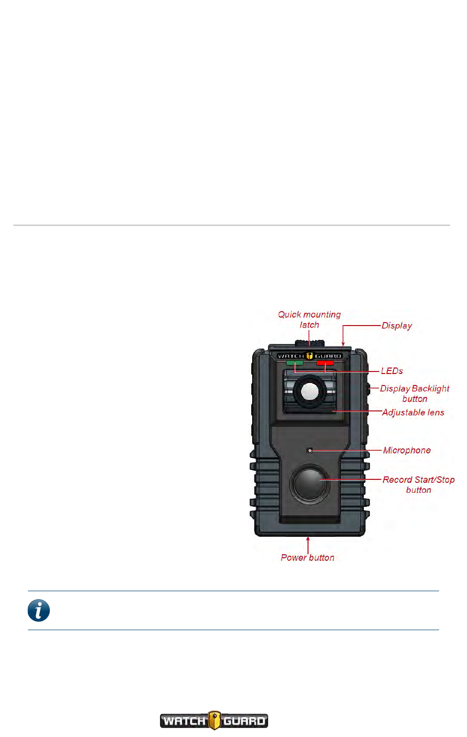
VISTA and VISTA WiFi
VISTA is an all-in-one HD body camera that does not include Wi-Fi® or GPS. VISTA WiFi is an
all-in-one HD camera that includes Wi-Fi and GPS.
VISTA and VISTA WiFi components include:
lCamera sensor and lens (page 49)
lMicrophone (page 49)
lButtons (page 49)
oPower
oRecord Start/Stop
oDisplay Backlight
lDisplay (page 50)
lFeedback indicators (page 57)
oTones
oVibration
oLEDs
lStorage (page 57)
lBattery (page 59)
lWi-Fi (VISTA WiFi only) (page 61)
lGPS (VISTA WiFi only) (page 62)
lQuick mounting latch (page 59)
Note: If you are not sure whether your equipment includes the Wi-Fi feature,
contact your WatchGuard representative.
48
VISTA Body Camera
WGD00120 Revision
ReviewDraft_111518
Camera sensor and lens
Camera sensor and lens
The camera sensor for VISTA and VISTA WiFi is an ultra-wide dynamic range (U-WDR) image
sensor. This sensor:
lMaintains rich colors at all light levels
lIncreases low-light sensitivity
The 130-degree wide-angle lens rotates vertically +/-20 degrees. Position the lens aiming at
the horizon.
Microphone
VISTA and VISTA WiFi use a digital microphone to record CD quality sound with minimal
distortion and wind noise.
Depending on the configuration applied to the camera, the microphone:
lContinuously records audio (default setting)
or
lOnly records audio when you press the Record Start/Stop button
You can mute the microphone, depending on the camera's configuration, using the Display
Backlight button. For more information, see Muting the Audio During a Recorded Event on
page 28.
Buttons
VISTA and VISTA WiFi have three buttons that control the camera's functionality:
lPower button
lRecord Start/Stop button
lDisplay Backlight button
Power button
Use the Power button to power the camera on or off as
well as place it in Covert Mode. The Power button is on
the bottom of the camera.
For instructions how to power the camera on and off, see
Powering On and Off on page 24. For more information
about placing the camera in Covert Mode, see Covert Mode
on page 77.
VISTA Body Camera
WGD00120 Revision
ReviewDraft_111518
49
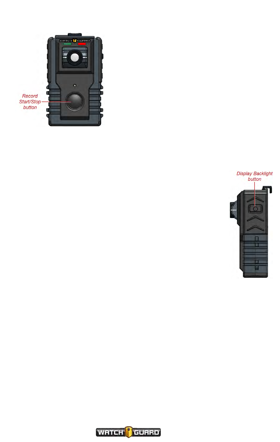
About the VISTA Body Camera
Record Start/Stop button
Use the Record Start/Stop button to start or stop a
recorded event on the camera. The Record
Start/Stop button is on the front of the camera.
For instructions how to start and stop a recorded
event on the camera, see Starting and Stopping a
Recorded Event on page 26.
Display Backlight button
Use the Display Backlight button for multiple functions, including:
lTurning on the backlight for the camera's display
lShowing the camera's status on the display
lAborting the sequence of status information on the display
lMuting the audio during a recording (see Muting the Audio During a
Recorded Event on page 28)
lSelecting an event category to assign to a recording (see Categorizing a
Recorded Event on page 29)
lTurning on VISTA WiFi's access point (hotspot) for the SmartConnect
smartphone application (see Appendix A: Using VISTA SmartConnect on
page 89)
lCanceling the sleep warning period (see Sleep Power State on page 74)
lCanceling the maximum recording time warning period (see Maximum
Recorded Event Time on page 76)
The Display Backlight button is on the right side as you look at the front of
the camera.
Display
The display on VISTA and VISTA WiFi shows a number of icons and messages to indicate the
status of the camera. The icons show in the top half of the display; the messages show in the 8-
character area on the bottom half of the display. If a message is longer than 8 characters, the
message scrolls. The display is on the top of the camera.
50
VISTA Body Camera
WGD00120 Revision
ReviewDraft_111518
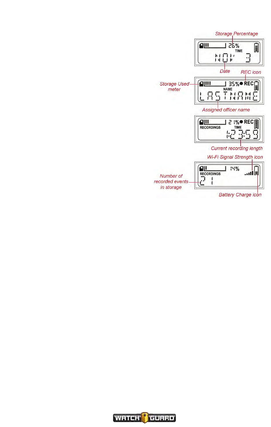
Display
The display informs you of:
lBattery status
As the charge level decreases, the number of
bars in the Battery Charge icon decreases
(see Battery on page 59).
lCurrent recording length
The recorded event length shows in the form
HH:MM:SS, for example, 1:23:59, and
includes any configured pre-event time (see
Pre-Event Capture on page 71).
lDate and time
The date shows as an abbreviation for the
month with a 1- or 2-digit day of the month,
for example, NOV 3.
lEvent categories
Each category shows in the 8-character area
as you cycle through the list, for example,
DOMESTIC. If the item is longer than 8
characters, the item scrolls. The list of
categories is configured in your Evidence
Library software (see Categorizing a Recorded
Event on page 29).
lNumber of recorded events in storage
lOfficer name
lRecording status
The REC icon (lREC) shows whether the camera is currently recording.
lSaved storage total
The saved storage total shows as a decimal value in GB, for example, 11.07 GB.
lStorage status
As the camera storage fills with recorded events, the Storage Used meter fills with bars and
the Storage Percentage increases (see Storage on page 57).
lUpload status, if docked in the VISTA Transfer Station or the VISTA WiFi Base
The upload status shows the number of events uploaded out of the total number of events to
upload. Critical events upload first (see Uploading events on page 37).
lWi-Fi or GPS signal status (VISTA WiFi only)
Most of the time, the Wi-Fi Signal Strength icon shows the status of VISTA WiFi's Wi-Fi
connection with the WiFi Base (see VISTA WiFi Base on page 66). During the status
information sequence (shows on the display when you press the Display Backlight button),
the Wi-Fi Signal Strength icon shows the status of the GPS signal (see GPS on page 62).
When the camera is not recording, the default message shown on the display is the number of
recorded events in storage. When the camera is in Covert Mode and not recording, the default
shown on the display is COVERT. When the camera is recording, the default shown on the
display is the current recording length.
VISTA Body Camera
WGD00120 Revision
ReviewDraft_111518
51
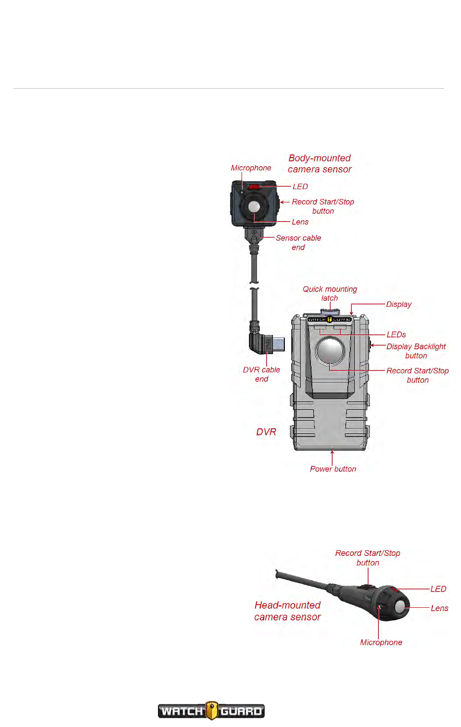
About the VISTA Body Camera
VISTA XLT
VISTA XLT is a two-piece body-worn camera system with an HD camera sensor separate from
the camera DVR. It includes Wi-Fi® and GPS.
VISTA XLT components include:
lCamera sensor (below)
oLens
oMicrophone
lButtons (page 53)
oPower
oTwo (2) Record Start/Stop
(DVR and camera sensor)
oDisplay Backlight
lDisplay (page 54)
lFeedback indicators (page 57)
oTones
oVibration
oLEDs
lStorage (page 57)
lBattery (page 59)
lWi-Fi (page 61)
lGPS (page 62)
lQuick mounting latch (page 59)
Camera sensor
The VISTA XLT HD camera sensor holds the
lens and the microphone for the VISTA XLT camera system. WatchGuard offers two HD camera
sensors for the VISTA XLT:
lHead-mounted
lBody-mounted
VISTA XLT's sensor is an ultra-wide dynamic range
(U-WDR) image sensor. This sensor:
lMaintains rich colors at all light levels
lIncreases low-light sensitivity
52
VISTA Body Camera
WGD00120 Revision
ReviewDraft_111518
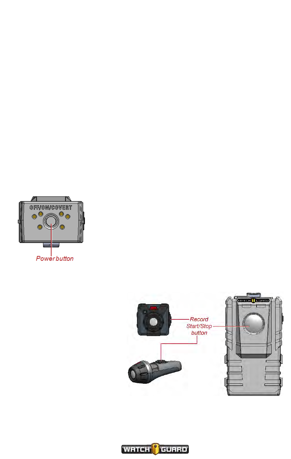
Buttons
VISTA XLT uses a digital microphone to record CD quality sound with minimal distortion and
wind noise. Depending on the configuration applied to the camera, the microphone:
lContinuously records audio
or
lOnly records audio when you press the Record Start/Stop button
You can mute the microphone, depending on the camera's configuration, using the Display
Backlight button. For more information, see Muting the Audio During a Recorded Event on
page 28.
Buttons
VISTA XLT has four buttons that control the camera's functionality:
lPower button
lTwo (2) Record Start/Stop buttons
lDisplay Backlight button
Power button
Use the Power button to power VISTA XLT on or off as well
as place it in Covert Mode. The Power button is on the
bottom of the DVR.
For instructions how to power the camera on and off, see
Powering On and Off on page 24. For more information
about placing the camera in Covert Mode, see Covert Mode
on page 77.
Record Start/Stop button
Use either Record Start/Stop
button to start or stop a recorded
event on VISTA XLT. One Record
Start/Stop button is on the front of
the DVR, the other is on the side of
either camera sensor.
For instructions how to start and stop
a recorded event on the camera, see
Starting and Stopping a Recorded
Event on page 26.
VISTA Body Camera
WGD00120 Revision
ReviewDraft_111518
53
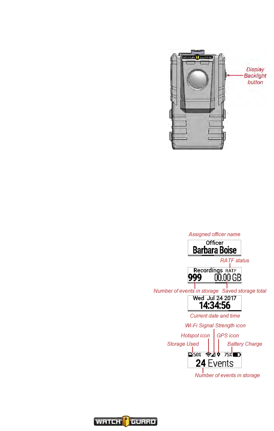
About the VISTA Body Camera
Display Backlight button
Use the Display Backlight button for multiple
functions, including:
lTurning on the backlight for the camera's display
lShowing the camera's status on the display
lAdvancing through the sequence of status
information on the display
lMuting the audio during a recording (see Muting
the Audio During a Recorded Event on page 28)
lSelecting an event category to assign to a recording
(see Categorizing a Recorded Event on page 29)
lTurning on VISTA XLT's access point (hotspot) for
the SmartConnect smartphone application (see
Appendix A: Using VISTA SmartConnect on page
89)
lCanceling the sleep warning period (see Sleep Power State on page 74)
lCanceling the maximum recording time warning period (see Maximum Recorded Event Time on
page 76)
The Display Backlight button is on the right side as you look at the front of the DVR.
Display
The display on VISTA XLT can show a number of
icons and messages to indicate the status of the
camera. When the icons are present, they show in
the top half of the display. Messages can show on
any part of the display. The display is on the top of
the camera.
The display informs you of:
lBattery status
The Battery Charge icon and percentage
show the charge level of the battery (see
Battery on page 59).
lCurrent event length
The recorded event length shows in the form
HH:MM:SS, for example, 1:23:59, and
includes any configured pre-event time (see
Pre-Event Capture on page 71).
lDate and time
lDevice ID
54
VISTA Body Camera
WGD00120 Revision
ReviewDraft_111518
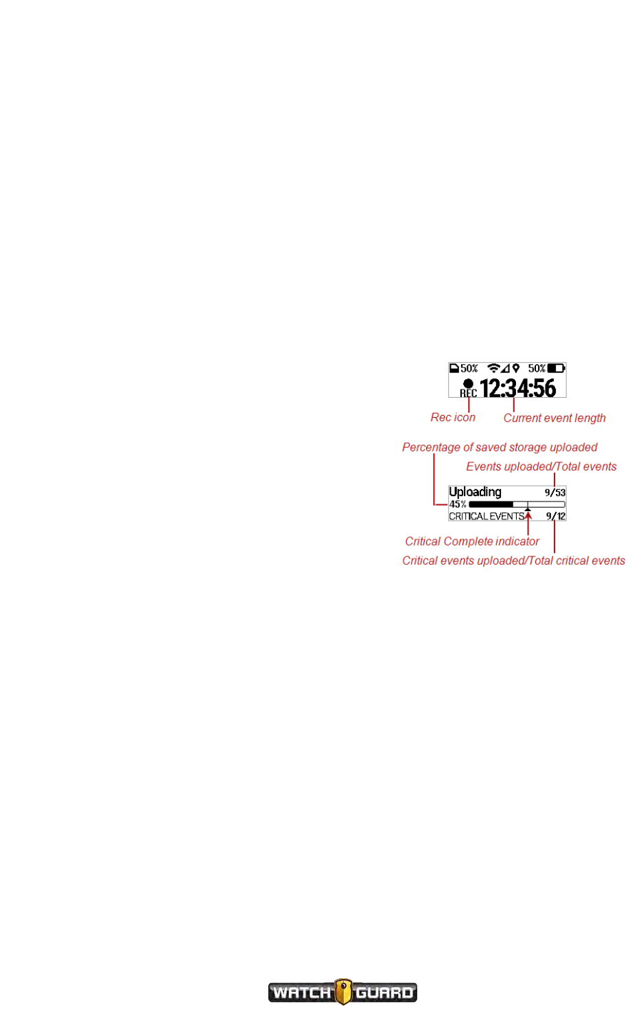
Display
lEvent categories
Each category shows in the display as you cycle through the list, for example, DOMESTIC. The
list of categories is configured in your Evidence Library software (see Categorizing a Recorded
Event on page 29).
lGPS status
The presence of the GPS icon shows that the camera currently has GPS lock.
lHotspot status
The presence of the Hotspot icon shows that the hotspot is currently on.
lNumber of recorded events in storage
lOfficer name
lRATF status
RATF on the Recordings information screen shows that RATF (Record-After-the-Fact®) is
enabled.
lRecording status
The REC icon shows whether the camera is
currently recording.
lSaved storage total
The saved storage total shows as a decimal
value in GB, for example, 11.07 GB.
lStorage status
The Storage Used icon and percentage show
how much storage has been used for recorded
events (see Storage on page 57).
lUpload status, if docked in the VISTA Transfer
Station or the VISTA WiFi Base
The upload status shows the number of events
uploaded out of the total number of events to upload. Critical events upload first and are listed
separately on the Uploading screen (see Uploading events on page 37).
lWi-Fi signal status
The Wi-Fi Signal Strength icon shows the status of VISTA XLT's Wi-Fi connection with the
WiFi Base (see VISTA WiFi Base on page 66).
When the camera is not recording, the default message shown on the display is the number of
recorded events in storage. When the camera is in Covert Mode and not recording, the default
shown on the display is COVERT. When the camera is recording, the default shown on the
display is the current event length.
VISTA Body Camera
WGD00120 Revision
ReviewDraft_111518
55

About the VISTA Body Camera
Information Sequence
The information sequence is a set of informational screens the VISTA Body Camera uses to give
you the current status of the camera. The information sequence shows on the display
automatically as part of the bootup process when you power the camera on. You can also bring
up the information sequence on-demand.
VISTA and VISTA WiFi
On VISTA and VISTA WiFi, you press the Display Backlight button once to start the
information sequence. The screens appear in the following order:
1. Number of recorded events in storage
2. Total saved storage in GB
3. Officer name
4. 24-hour time in the format HH:MM:SS
5. Date in the format MMM DD
MMMis the abbreviation for month, for example, JAN.
You can press the Display Backlight button at any point to abort the rest of the information
sequence.
VISTA XLT
On VISTA XLT, you press the Display Backlight button twice within 2 seconds to start the
information sequence. The screens appear in the following order:
1. Number of recorded events in storage and total saved storage in GB
This screen also shows RATF if RATF is enabled in the device configuration.
2. Officer name
3. Date in the format DDD MMM DD YYYY and 24-hour time in the format HH:MM:SS
DDD is the abbreviation for the day name, for example, MON. DD is the abbreviation for the
date number, for example, 15. MMM is the abbreviation for month, for example, JAN.
4. Device ID
You can press and release the Display Backlight button to manually advance through
information sequence screens. Without manually advancing the sequence, each screen stays
on the display about 4 seconds.
56
VISTA Body Camera
WGD00120 Revision
ReviewDraft_111518
Feedback indicators
Feedback indicators
Apart from the displays, all models of VISTA Body Camera can provide feedback on their status
using:
lTones
lVibration
lRed and green LEDs
All of these feedback indicators are configurable in your Evidence Library software. You can set
up the tones and vibration to alert with:
lTone only
lVibration only
lTone and vibration together
lNo tone or vibration
You can configure the brightness level of the LEDs or set them to adjust automatically
depending on the time of day.
Note: If you place the camera in Covert Mode, no tones sound and the LEDs do
not light. VISTA XLT inverts its display. For information about placing the camera
in Covert Mode, see Covert Mode on page 77.
Storage
The VISTA Body Camera can store about 12 hours of HD (high definition) video.
When you need to free up storage space on the camera, you upload recorded events from the
camera to your Evidence Library software. For information about uploading events to Evidence
Library, see Uploading events on page 37.
The VISTA Body Camera offers some special features to help you conserve storage space. For
more information, see Battery and storage saving special features on page 70.
VISTA Body Camera
WGD00120 Revision
ReviewDraft_111518
57

About the VISTA Body Camera
VISTAand VISTA WiFi
VISTA and VISTA WiFi's display shows a Storage Used meter and a Storage
Percentage to indicate how much of the storage has been used for protected
video/audio (recorded events). As the camera records events and its storage fills,
the Storage Used meter fills with bars and the Storage Percentage number
increases. For information about protected video/audio, see Video, Audio, and Subtitle Evidence
on page 46.
When the meter shows bars, video evidence has been saved in storage. The Storage
Percentage number shows the corresponding percentage of storage used.
When the Storage Used meter shows all ten bars, storage is more than 90
percent full (the Storage Percentage number will show 91% or higher). You
should dock the camera to import video to your Evidence Library software as soon
as possible.
VISTA XLT
VISTA XLT's display shows a Storage Used icon and percentage to indicate how much
of the storage has been used for protected video/audio (recorded events). As the camera
records events and its storage fills, the Storage Used icon fills with black and the
percentage increases. For information about protected video/audio, see Video, Audio,
and Subtitle Evidence on page 46.
When the icon has any black filled in, video evidence has been saved in storage. The percentage
shows the corresponding percentage of storage used.
When the icon is completely filled with black, storage is more than 90 percent full (the
percentage will show 91% or higher). You should dock the camera to import video to your
Evidence Library software as soon as possible.
Low storage and full storage messages
When the camera is about 10 minutes away from running out of storage space, it alerts you
with:
lTwo short tones and/or a vibration (depending on the alert configuration settings)
lSlow-blinking red LED and Storage Used meter/icon on the display
When the camera storage is full, it alerts you again with an error condition alert:
lFast-blinking red LED
lThree short tones and/or a vibration (depending on the alert configuration settings)
lError message on the display
Warning! If storage fills completely, the camera stops recording new video.
58
VISTA Body Camera
WGD00120 Revision
ReviewDraft_111518

Battery
Battery
The VISTA Body Camera uses a lithium-polymer (LiPo) battery.
WatchGuard recommends that you use the USB Base, connected to an electrical outlet, or the
VISTA Transfer Station when fully charging the VISTA Body Camera battery.
Caution: To prevent possible damage to some computers, connect the USB
Base to the computer through the approved USB hub (Sabrent 7-Port USB 2.0
Hub, WatchGuard part number WGP02364).
Charging in a vehicle base can impact the vehicle battery and can slow down significantly in
warmer temperatures. For the best battery life and fastest charging times, you should charge
the VISTA Body Camera in a cooler environment.
Important! Battery charging shuts down at ambient temperatures greater
than 35 degrees C (95 degrees F).
The VISTA Body Camera offers a number of special features to help you conserve battery
power. For more information, see Battery and storage saving special features on page 70.
VISTA and VISTAWiFi
The VISTA and VISTA WiFi batteries can fully charge in 3 to 5 hours when docked in a USB Base
connected to an electrical outlet or in a VISTA Transfer Station.
VISTA is available in two battery versions:
lStandard capacity battery
VISTA with the standard capacity battery weighs 4.3 ounces and can continuously record HD
(high definition) quality video for about 7 hours.
lExtended capacity battery
VISTA with the extended capacity battery weighs 5.3 ounces and can continuously record HD
quality video for about 11 hours.
VISTA WiFi is only available with the extended capacity battery and can continuously record HD
quality video for:
lAbout 9 hours with GPS enabled
lAbout 10 hours with GPS disabled
The camera's display shows a Battery Charge icon that indicates the charge level of the
battery. When the icon shows the battery with all five bars, the battery is fully charged.
When the icon shows fewer than five bars, the charge level of the battery is less than fully
charged.
VISTA Body Camera
WGD00120 Revision
ReviewDraft_111518
59
About the VISTA Body Camera
When the Battery Charge icon shows only the outline, the battery charge is less than 10
percent; in this case, you should dock VISTA to charge as soon as possible. For instructions
how to charge the VISTA battery, see Charging the battery on page 42.
When VISTA has nearly run out of battery power (less than 5 percent of full capacity
remaining), the camera alerts you with:
lTwo tones and/or a vibration (depending on VISTA's alert configuration settings)
lSlow-blinking red LED and Battery Charge icon on the display
VISTA XLT
VISTA XLT's battery can fully charge in about 7 hours when docked in a USB Base connected to
an electrical outlet or in a VISTA Transfer Station.
The DVR part of the VISTA XLT system contains the battery. The DVR weighs 6.2 ounces and
can continuously record the highest HD quality video for:
lAbout 10 hours with GPS enabled
lAbout 12 hours with GPS disabled
VISTA XLT's display shows a Battery Charge icon and percentage that indicate the
charge level of the battery. When the icon is completely filled and the percentage shows
100%, the battery is fully charged.
As the battery is used, the icon slowly empties and the percentage lowers. When the
battery charge is less than 10 percent, you should dock the camera to charge as soon as
possible. For instructions how to charge the VISTA XLT battery, see Charging the battery
on page 42.
When VISTA XLT has nearly run out of battery power (less than 5 percent of full capacity
remaining), the camera alerts you with:
lTwo tones and/or a vibration (depending on the camera's alert configuration settings)
lSlow-blinking red LED and Battery Charge icon/percentage on the display
LOW BATT/LOW BATTERY message
The LOW BATT (VISTA and VISTA WiFi) or LOW BATTERY (VISTA XLT) message appears on
the display when you push the Power button to power the camera up, but the battery charge
level is so low that the camera cannot successfully power up. You should dock the camera
(VISTA and VISTA WiFi) or DVR (VISTA XLT) to charge as soon as possible.
LOW BASE message
The LOWBASEmessage appears on the display when the camera (VISTA and VISTA WiFi) or
DVR (VISTA XLT) is docked, but the dock is not providing enough power to charge the camera.
If the camera is docked in a USBBase, make sure the base is connected to an electrical outlet.
The VISTA Body Camera can charge in a USB Base connected to the USBport on a computer,
60
VISTA Body Camera
WGD00120 Revision
ReviewDraft_111518
OVERTEMP message
depending on the amount of power provided by the USB port. The camera charges significantly
faster when docked in a USB Base plugged into an electrical outlet.
Caution: To prevent possible damage to some computers, connect the USB
Base to the computer through the approved USB hub (Sabrent 7-Port USB 2.0
Hub, WatchGuard part number WGP02364).
If the camera is docked in a Transfer Station, move the camera to another slot in the Transfer
Station. If the camera continues to read LOW BASE in the Transfer Station, contact
WatchGuard Customer Service.
OVERTEMP message
The OVERTEMP message appears on the display when the camera (VISTA and VISTA WiFi) or
DVR (VISTA XLT) is docked, but the battery is unable to charge due to excessive heat. The
camera will continue to try to charge as it cools down.
Important! Battery charging shuts down at ambient temperatures greater
than 35 degrees C (95 degrees F).
Tip: For the best battery life and fastest charging times, WatchGuard
recommends that you charge the VISTA Body Camera in a cooler environment.
Wi-Fi
Note: Not all VISTA Body Cameras or VISTA bases have the Wi-Fi® feature. If
you are not sure whether your equipment has Wi-Fi, contact your WatchGuard
representative.
The VISTA WiFi and VISTA XLT cameras include built-in Wi-Fi (802.11n).
Note: VISTA WiFi and VISTA XLT also include GPS capability. For more
information, see GPS on page 62.
The Wi-Fi feature allows VISTA WiFi and VISTA XLT to pair with the VISTA WiFi Base. Once the
camera and the base are paired, the camera is associated with the local recording group. For
more information about pairing VISTA WiFi and VISTA XLT with the WiFi Base, see VISTA WiFi
and VISTAXLT: Associating with a recording group on page 44.
The Wi-Fi feature also allows VISTA WiFi and VISTA XLT to operate as a Wi-Fi access point
(hotspot) for the VISTA SmartConnect smartphone application.
VISTA Body Camera
WGD00120 Revision
ReviewDraft_111518
61
About the VISTA Body Camera
VISTA WiFi
When VISTA WiFi is paired with the WiFi Base, the camera display shows a Wi-Fi Signal
Strength icon ( ) that indicates the strength of the Wi-Fi signal coming from the WiFi Base.
VISTAXLT
When VISTA XLT is paired with the WiFi Base, the camera display shows a Wi-Fi Signal
Strength icon ( ) that indicates the strength of the Wi-Fi signal coming from the WiFi Base.
When VISTA XLT is operating as a hotspot for the SmartConnect app, the camera display shows
aHotspot icon ( ).
For more information about...
Recording groups, see Using VISTAWiFi or VISTA XLT with a Recording Group on page 79.
Connecting SmartConnect with the camera, see Appendix A: Using VISTA SmartConnect on
page 89.
GPS
The VISTA WiFi and VISTA XLT cameras include built-in GPS (Global Positioning System).
Note: VISTA WiFi and VISTA XLT also include Wi-Fi capability. For more
information, see Wi-Fi on page 61.
VISTA WiFi and VISTA XLT use the GPS feature to apply:
lAccurate timestamps to recorded events
These timestamps allow your Evidence Library software to synchronize playback between
events (video and/or audio) from VISTA WiFi or VISTA XLT cameras and/or 4RE DVRs.
lGPS location coordinates to VISTA WiFi and VISTA XLT recorded events
Both the timestamps and the location coordinates are included in the subtitles during playback
in your Evidence Library software.
Note: The GPS feature can be disabled in your Evidence Library software
configuration, if you need to conserve power.
62
VISTA Body Camera
WGD00120 Revision
ReviewDraft_111518
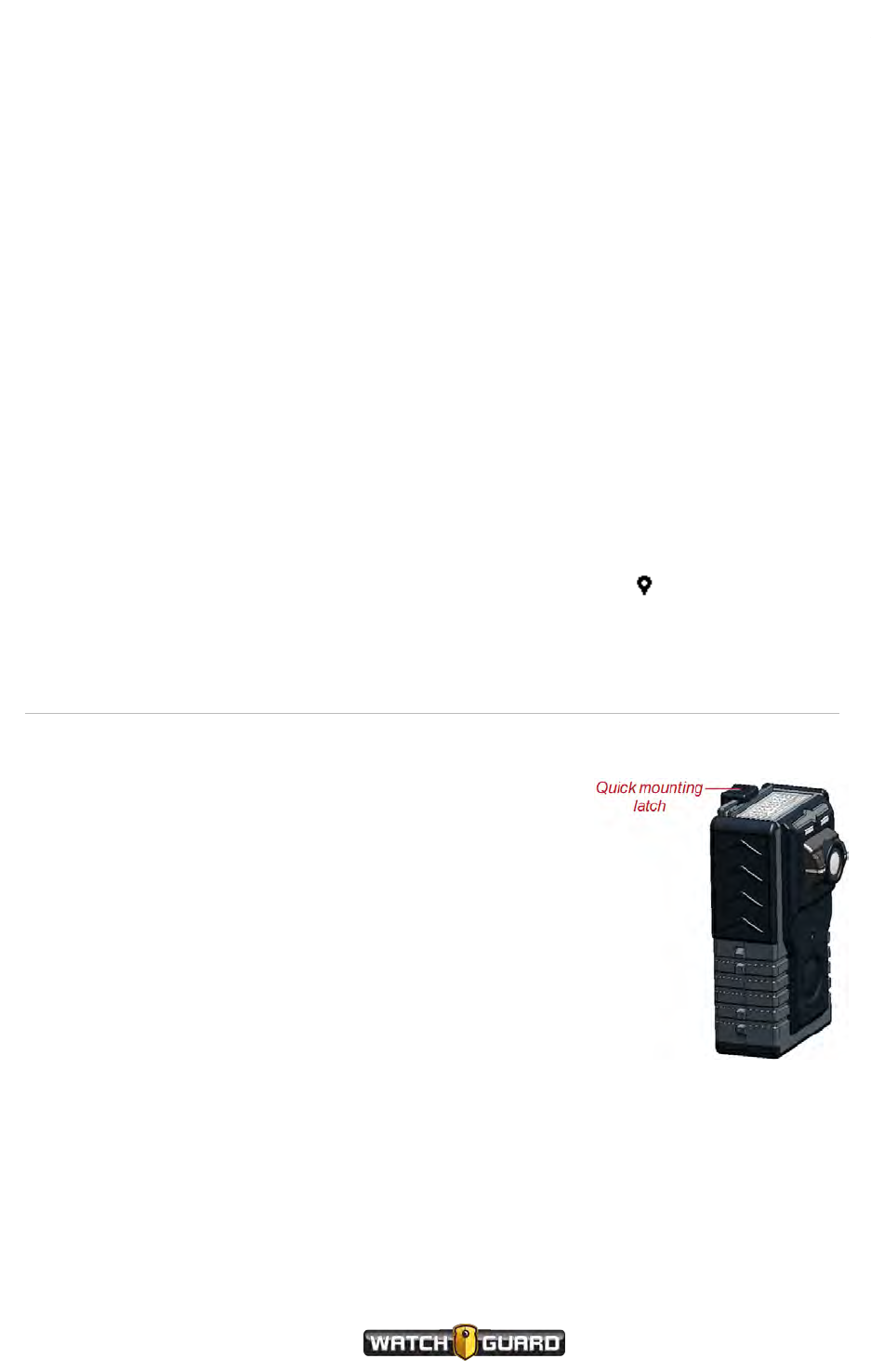
VISTA WiFi
VISTA WiFi
When the VISTA WiFi GPS finds its first lock after powering up, the camera display shows GPS
LOCK for 5 seconds.
If GPS is enabled on VISTA WiFi, you can see the status of a VISTA WiFi's GPS signal during the
status information sequence. The information sequence shows on the display when you press
the Display Backlight button.
During the information sequence, VISTA WiFi uses the bars of the Wi-Fi Signal Strength icon
to communicate the camera's GPS lock status:
l0 bars: GPS has never locked since the camera's last reboot
l1 bar: GPS has locked at least one time since the camera's last reboot, but is NOT currently
locked
l5 bars: GPS is actively locked
VISTA XLT
When the VISTA XLT GPS finds its first lock after powering up, the camera display shows
GPSLOCK for 5 seconds.
When VISTA XLT has GPS lock, the camera display shows the GPS icon ( ).
Quick mounting latch
The quick mounting latch on VISTA and VISTA WiFi attaches to
the mounting tab on any of their mount options. The quick
mounting latch on the VISTA XLT DVR attaches to DVR
mounting options.
Slide the latch over the tab on the mount to attach or release
the camera.
For more information about mounting options for VISTA and
VISTA WiFi, see Wearing VISTA and VISTAWiFi on page 15.
For more information about mounting options for VISTA XLT,
see Wearing VISTA XLT on page 19.
VISTA Body Camera
WGD00120 Revision
ReviewDraft_111518
63
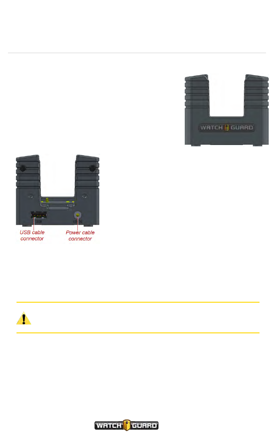
About the VISTA Body Camera
USB Base
When you dock the VISTA Body Camera in the USB Base, the
camera automatically starts charging, if needed. The camera
also uses the USB Base for:
lUploading recorded events from storage
lProvisioning the camera
lUpdating firmware
lDefining a Record-After-the-Fact®(RATF) event
lRequesting a state capture for troubleshooting
Connections
The USB Base has connections for both a power cable
and a USB cable. For instructions how to set up the
VISTA USB Base, see Setting up the VISTA USB Base
below.
For more information about using the VISTA Body
Camera with the USB Base, see Docking the VISTA
Body Camera in a USB Base on page 31.
Setting up the VISTA USB Base
To set up the USB Base to use with a VISTA Body Camera and your Evidence Library software:
Caution: To prevent possible damage to some computers, connect the USB
Base to the computer through the approved USB hub (Sabrent 7-Port USB 2.0
Hub, WatchGuard part number WGP02364).
1. Set up the approved USB hub and connect it to the computer where your Evidence Library
software is located.
2. Plug the power cable for the USB Base into an electrical outlet.
3. Connect the power cable to the USBBase.
4. Connect the USB cable to the USBBase and then into the approved USB hub.
64
VISTA Body Camera
WGD00120 Revision
ReviewDraft_111518
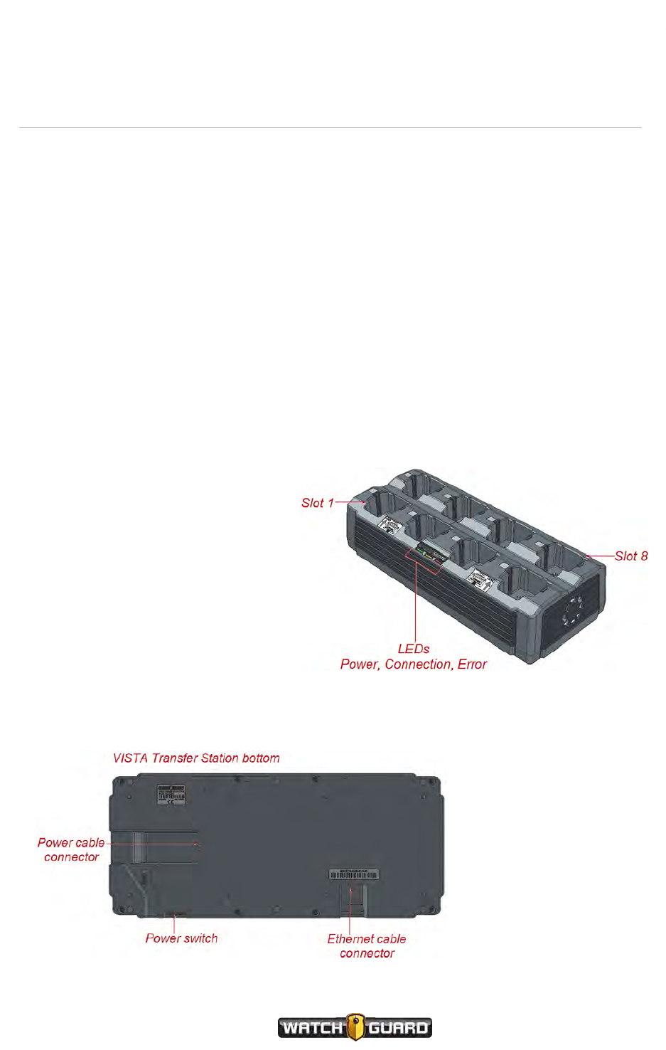
VISTA Transfer Station
VISTA Transfer Station
When you dock the VISTA Body Camera in the VISTA Transfer Station, the camera
automatically starts charging, if needed. The camera also uses the Transfer Station for:
lUploading recorded events from storage
lProvisioning the camera
lUpdating firmware automatically
The VISTA Transfer Station allows your agency's Evidence Library software to interact with
multiple VISTA Body Cameras simultaneously. You can connect multiple Transfer Stations to
one instance of Evidence Library software.
Each Transfer Station has eight slots for cameras.
LEDs
Three LEDs on the Transfer Station show power and connection status:
lGreen, left position: When lit,
indicates that the Transfer
Station is powered on
lAmber, center position: When
lit, indicates that the Transfer
Station is connected to Evidence
Library software; when blinking,
indicates data is being transferred
lRed, right position: When lit,
indicates an error condition
Connections
The Transfer Station has connections for both a power cable and an Ethernet cable. You power
the Transfer Station off and on using the power switch.
VISTA Body Camera
WGD00120 Revision
ReviewDraft_111518
65
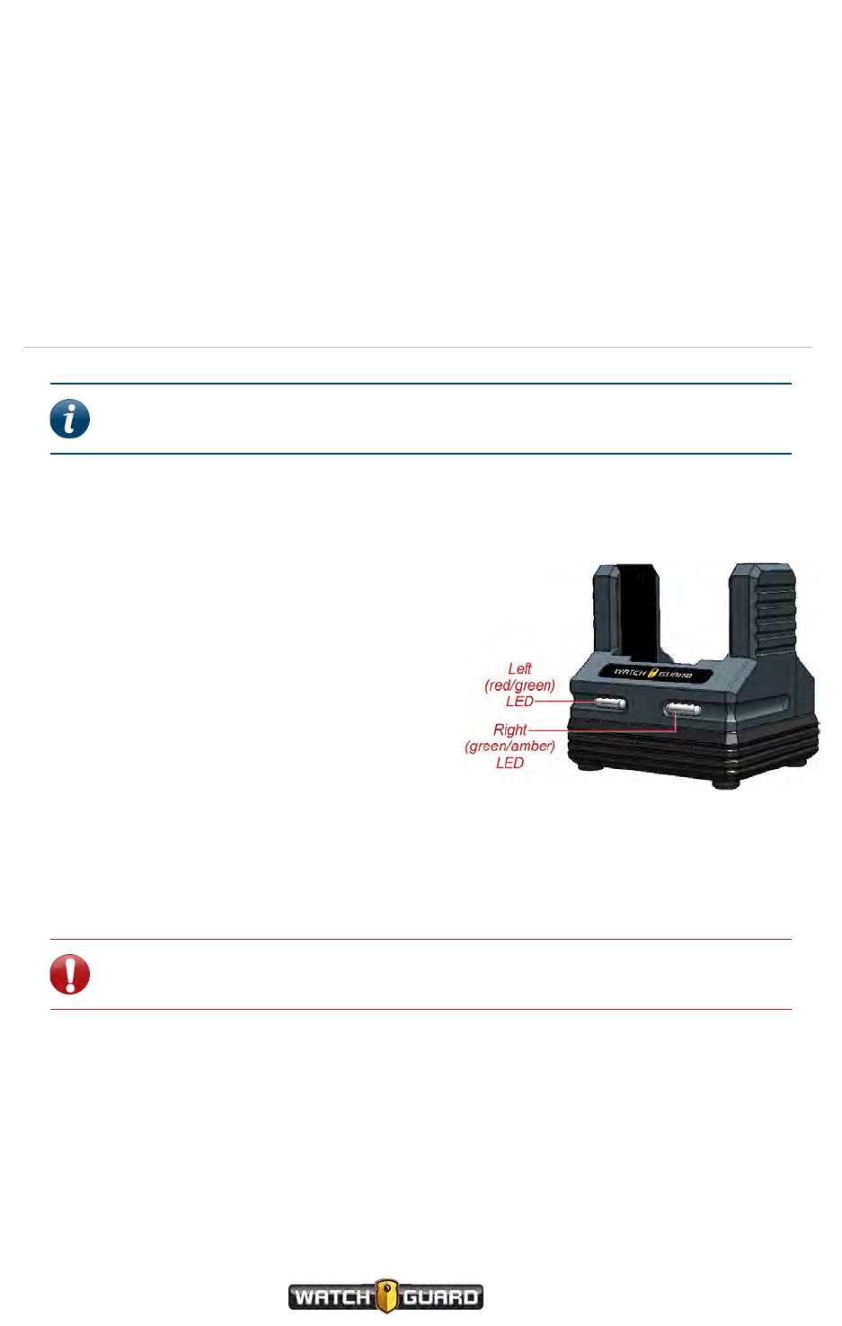
About the VISTA Body Camera
For more information about using VISTA Body Cameras with the Transfer Station, see Docking
the VISTA Body Camera in a VISTA Transfer Station on page 33.
Setting up the VISTA Transfer Station
For instructions how to set up the VISTA Transfer Station, see Appendix D: VISTA Transfer
Station Setup on page 117.
VISTA WiFi Base
Note: Not all VISTA Body Cameras or bases have the Wi-Fi® feature. For more
information, contact your WatchGuard representative.
When you dock the VISTA WiFi or VISTA XLT camera in the VISTA WiFi Base, the camera pairs
with the base. The camera can use the WiFi Base for:
lAssociating with a local recording group
The WiFi Base acts as the Wi-Fi access point
(802.11n hotspot) for VISTA WiFi or VISTA
XLT to connect to the local recording group
network. The broadcast range for the WiFi
Base depends on its current environment.
lUpdating firmware
lUploading recorded events from storage
(only with an Evidence Library 4 Web
connection)
lCharging the camera's battery
You should only use the WiFi Base for
incidental charging during your shift.
Charging in a vehicle base can impact the vehicle battery and can slow down significantly in
warmer temperatures.
Important! Battery charging shuts down at ambient temperatures greater
than 35 degrees C (95 degrees F).
66
VISTA Body Camera
WGD00120 Revision
ReviewDraft_111518

LEDs
LEDs
Two bi-color LEDs on the front of the WiFi Base show power and connection status. The left
LEDis either red or green.
Left LED (red/green)
LED state VISTAWiFi Base state
Off Powered off
Red Undefined
Green Powered on
Blinking red Error condition
Blinking green In shutdown or wireless upload timeout
period
The left LED on the WiFi Base blinks green a number of times when it successfully pairs with a
VISTA WiFi or VISTA XLT camera. The left LED blinks red a number of times if the pairing was
not successful.
The right LED is either green or amber.
Right LED (green/amber)
LED state
VISTA WiFi docked
state VISTAWiFi Base state
Off --- Not connected to camera or
upload server
Amber Docked Connected to upload server
Green Not docked Connected to camera (Wi-
Fi connection)
Blinking amber Docked Activity with upload server
Blinking green Not docked Activity with camera (Wi-Fi
connection)
If two cameras are paired with the same VISTA WiFi Base, and one is docked, the WiFi Base
LEDs show the state of the DOCKED camera and WiFi Base pair.
VISTA Body Camera
WGD00120 Revision
ReviewDraft_111518
67
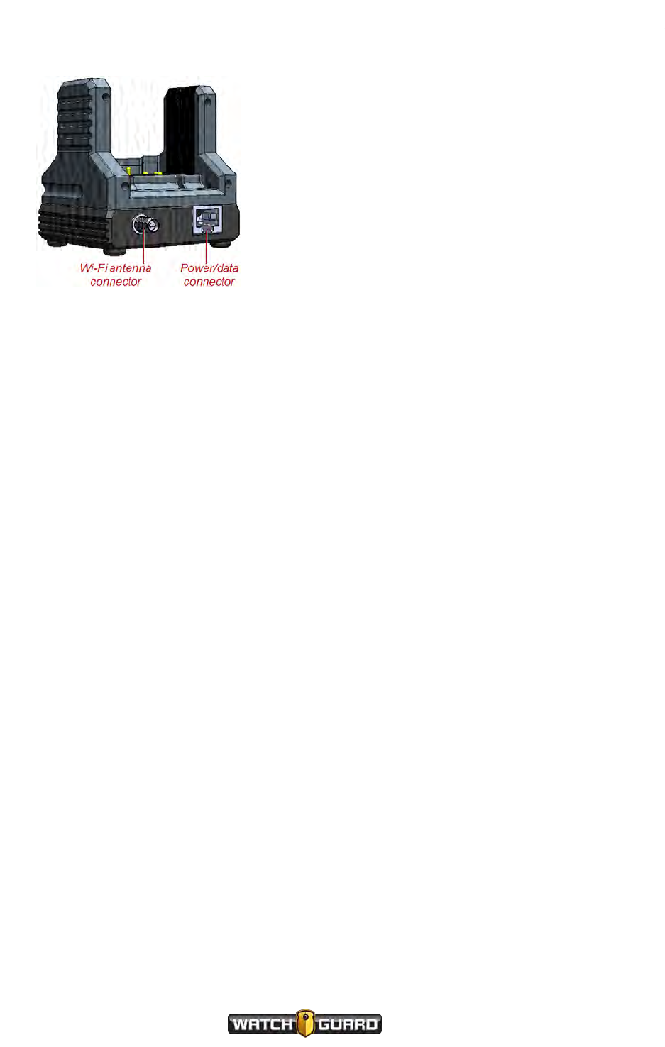
About the VISTA Body Camera
Connections
The WiFi Base has connections for a Wi-Fi antenna
cable and a WatchGuard-provided custom power/data
cable on the back.
The WiFi Base power/data cable must connect to the
Smart Power Switch. For more information about the
WiFi Base as part of the local recording group network,
see Using VISTAWiFi or VISTA XLT with a Recording
Group on page 79.
For more information about...
Using VISTA WiFi or VISTA XLT with the WiFi Base, see Docking the VISTABody Camera in a
WiFi Base on page 34.
Upgrading the WiFi Base, see Upgrading the VISTA WiFi Base and the Smart Power Switch on
page 115.
Setting up the VISTA WiFi Base
Typically, the VISTA WiFi Base, its windshield antenna, and the Smart Power Switch are
installed in the vehicle by your agency's installation technicians. For more information about
installing the VISTA WiFi system equipment in the vehicle, see the 4RE Vehicle Installation
Instructions.
68
VISTA Body Camera
WGD00120 Revision
ReviewDraft_111518

VISTABody Camera Special Features
VISTABody Camera Special Features
In this section...
lPre-Event Capture (page 71)
lRecord-After-the-Fact®(page 72)
lForce Microphone On (page 73)
lSleep power state (page 74)
lAutomatic Off (page 75)
lMaximum Recorded Event Time (page 76)
lRecording Reminder Alert (page 77)
lCovert Mode (page 77)
VISTA Body Camera
WGD00120 Revision
ReviewDraft_111518
69

VISTABody Camera Special Features
Overview
The VISTA Body Camera has a number of special features that give you more recording options
and can help you save battery power and storage. The camera also has a Covert Mode that
turns off the camera tones and LEDs.
Recording special features
The VISTA Body Camera has the following special features related to recording:
lPre-Event Capture: Enable this feature to allow the camera to capture and save up to two
minutes of additional video prior to a recorded-event start (page 71)
lRecord-After-the-Fact®: Enable this feature to allow the camera to continuously capture
and save video that can generate a Record-After-the-Fact (RATF) event (page 72)
lForce Microphone On: Enable this feature to allow the camera to capture audio whenever it
is capturing and saving video (page 73)
Note: All of the recording special features are configured in your Evidence
Library software.
Battery and storage saving special features
The VISTA Body Camera has the following special features related to saving battery power and
storage space:
lSleep power state: Enable this feature to allow the camera to enter a low power state after a
period of time with no activity (page 74)
This feature can help save battery power.
lAutomatic Off: Enable this feature to allow the camera to turn itself off after a period of time
with no activity (page 75)
This feature can help save battery power.
lMaximum Recorded Event Time: Enable this feature to allow the camera to automatically
stop a recorded event when it reaches a specified duration (page 76)
This feature can help save storage space.
lRecording Reminder Alert: Enable this feature to allow the camera to notify you at regular
intervals that it is still capturing a recorded event (page 77)
This feature can help save storage space.
Note: All of the battery and storage saving special features are configured in
your Evidence Library software.
70
VISTA Body Camera
WGD00120 Revision
ReviewDraft_111518

Covert Mode
Covert Mode
With Covert Mode enabled, the VISTA Body Camera sounds no tones, lights no LEDs, and only
lights the Display Backlight on demand. For instructions how to enable Covert Mode on the
camera, see Covert Mode on page 77.
Pre-Event Capture
The Pre-Event Capture feature on the VISTA Body Camera allows you to capture and save up to
two minutes of additional video prior to a recorded-event start. You configure the Pre-Event
Capture feature in your Evidence Library software.
If the Pre-Event Capture feature is enabled, the camera is continuously capturing and saving
video whenever it is powered on and not asleep. When an event is started, manually or
automatically, up to two minutes of that saved video is added to the recorded event prior to the
event start time.
Note: VISTA WiFi and VISTA XLT can start a recorded event automatically when
associated with a recording group. For more information about starting events,
see Starting and Stopping a Recorded Event on page 26.
For example, you start a recorded event (by pressing Record Start/Stop) at 2:15 PM and stop
it (again pressing Record Start/Stop) at 2:35 PM. With a Pre-Event Capture time configured
for one minute, the recorded event includes video recorded from 2:14 PM to 2:35 PM.
For the Pre-Event Capture feature, in your Evidence Library software, you configure how much
pre-event time you want captured, from none up to two minutes.
Audio
Audio is NOT typically included with pre-event video. Typically, the VISTA Body Camera only
begins to record audio when you start a recorded event.
You can include audio whenever the camera is recording if you enable the Force Microphone On
feature. For information about this feature, see Force Microphone On on page 73.
For more information about...
Recorded events, see Video, Audio, and Subtitle Evidence on page 46.
Recording groups, see Using VISTAWiFi or VISTA XLT with a Recording Group on page 79.
VISTA Body Camera
WGD00120 Revision
ReviewDraft_111518
71
VISTABody Camera Special Features
Record-After-the-Fact®
The Record-After-the-Fact (RATF) feature on the VISTA Body Camera allows you to
continuously capture and save video you can use to generate an RATF event. You enable the
RATF feature in your Evidence Library software.
The VISTA Body Camera works as a DVR and camera combination to collect evidence in the
form of recorded events. When a recording is started and then stopped, automatically or
manually, the camera protects the segment between the recording start and stop as a recorded
event.
Note: VISTA WiFi or VISTA XLT can start and stop a recorded event
automatically when associated with a recording group. For more information
about starting and stopping events, see Starting and Stopping a Recorded Event
on page 26.
When you enable the RATF feature on the VISTA Body Camera, the camera captures and stores
video whenever it is powered on and not asleep; however, only the protected segment between
the event start and stop (automatic or manual) is considered a recorded event. Typically, only
recorded events are uploaded to your Evidence Library software.
For the RATF feature, in your Evidence Library software, you configure whether you want the
camera to continuously capture and save video or not.
Generating an RATF event
If the VISTA Body Camera has the RATF feature enabled, you can use your Evidence Library
software to send a manual request to the camera to generate and retrieve an RATF event. An
RATF event typically consists of video that was not originally part of a recorded event. For more
information about generating and retrieving an RATF event, see your Evidence Library software
user guide.
Note: The Evidence Library software can only send an RATF event request to a
VISTA Body Camera docked in the USBbase.
Storage
When RATF is enabled, the camera overwrites the oldest unprotected (non-recorded event)
area in storage with any newly captured video or recorded events. This process can continue
until the camera's storage is filled with recorded events (protected recordings). Then you must
upload recorded events to your Evidence Library software to free up storage space before you
can continue to use the camera.
72
VISTA Body Camera
WGD00120 Revision
ReviewDraft_111518

Audio
Audio
Audio is NOT typically included in the saved video when RATF is enabled. Typically, the VISTA
Body Camera only begins to record audio when a recorded event is started. This means that
audio is NOT typically included with RATF video that was not originally part of a recorded event
(protected recording).
You can include audio whenever the camera is capturing and saving video if you enable the
Force Microphone On feature. For information about this feature, see Force Microphone On
below.
For more information about...
Recorded events, see Video, Audio, and Subtitle Evidence on page 46.
Recording groups, see Using VISTAWiFi or VISTA XLT with a Recording Group on page 79.
Force Microphone On
The Force Microphone On feature of the VISTA Body Camera allows you to capture audio
whenever the camera is capturing and saving video. You enable the Force Microphone On
feature in your Evidence Library software.
Typically, audio is only captured during a recorded event. This means that even though the
camera may be configured to capture video all the time, if a recorded event is not started,
automatically or manually, thecamera does not record audio. (Audio is NOT typically included in
pre-event video or Record-After-the-Fact®(RATF) events.)
When you enable the Force Microphone On feature, the camera captures audio with the video
whenever it is capturing and saving video. This means that audio IS included with both pre-
event video and RATF events.
For the Force Microphone On feature, in your Evidence Library software, you configure whether
you want the VISTA Body Camera to capture audio whenever it is capturing and saving video or
not.
For more information about...
Recorded events, see Video, Audio, and Subtitle Evidence on page 46.
Pre-event video, see Pre-Event Capture on page 71.
RATF events, see Record-After-the-Fact® on page 72.
Recording groups, see Using VISTAWiFi or VISTA XLT with a Recording Group on page 79.
VISTA Body Camera
WGD00120 Revision
ReviewDraft_111518
73

VISTABody Camera Special Features
Sleep Power State
The Sleep power state on the VISTA Body Camera allows the camera to go into a low-power
state designed to help you conserve battery power. You configure the Sleep state in your
Evidence Library software.
When the VISTA Body Camera is configured for Sleep state, after a period of time with no
movement and/or button presses, the camera enters a low power state where it cannot
capture any video or audio.
The Sleep power state provides a significant reduction in power consumption. Starting with a
fully charged battery, the VISTA Body Camera can remain in its Sleep power state for more
than 30 hours before powering off due to a discharged battery.
For Sleep state, in your Evidence Library software you configure:
lWhether the camera will sleep or not
lWhat makes the camera sleep (lack of movement and/or button presses)
lHow much time must elapse with no activity before the camera goes to sleep
When the camera is asleep, the display reads SLEEP and the green LED blinks slowly. The
display continues to show battery and storage status indicators.
Sleep warning period
About 15 seconds before it goes to sleep, the camera warns you that it is about to go into Sleep
state:
lDescending tones sound with vibration (depending on the configured alert notification options)
lSLEEP blinks on the display
You can press the Display Backlight button or the Record Start/Stop button at any time to
keep the camera from going to sleep.
Note: Pressing the Record Start/Stop button also starts a recorded event.
Exiting Sleep state
TheVISTA Body Camera exits Sleep state when you move it or press a button. From Sleep
state, the camera is ready to record in about 1 second.
74
VISTA Body Camera
WGD00120 Revision
ReviewDraft_111518

Automatic Off
Automatic Off
The Automatic Off feature on the VISTA Body Camera allows the camera to turn itself off after a
period of time with no activity. You configure the Automatic Off feature in your Evidence Library
software.
If the Automatic Off feature is enabled, after a period of time with no movement and/or button
presses, the camera powers off.
For the Automatic Off feature, in your Evidence Library software you configure:
lWhether the camera will power off automatically or not
lWhat makes the camera power off (lack of movement and/or button presses)
lHow much time must elapse with no activity before the camera powers off
As the VISTA Body Camera powers down, the display reads Shutting Down, the green LED
turns off, and descending tones sound (depending on the configured alert notification options).
Automatic off warning period
About 15 seconds before it automatically powers off, the camera warns you that it is about to
power off:
lDescending tones sound with vibration (depending on the configured alert notification options)
lPOWEROFF blinks on the display
You can press the Display Backlight button or the Record Start/Stop button at any time to
keep the camera from going to sleep.
Note: Pressing the Record Start/Stop button also starts a recorded event.
VISTA Body Camera
WGD00120 Revision
ReviewDraft_111518
75

VISTABody Camera Special Features
Maximum Recorded Event Time
The Maximum Recorded Event Time feature on the VISTA Body Camera allows the camera to
automatically stop a recorded event when it reaches a specified duration. You configure the
Maximum Recorded Event Time feature in your Evidence Library software.
If the Maximum Recorded Event Time feature is enabled, when a recorded event reaches the
specified duration, the camera automatically stops the recorded event.
For the Maximum Recorded Event Time feature, in your Evidence Library software you
configure:
lWhether the camera will have a Maximum Recorded Event Time or not
lHow long a recorded event can be before the camera automatically stops it
Maximum Recorded Event Time warning period
Two minutes before it reaches the specified Maximum Recorded Event Time, the camera warns
you that it is about to stop the recorded event:
lTwo tones sound with a vibration (depending on the configured alert notification options)
lAUTOSTOP shows on the display
lFor the rest of the two-minute warning period, on the display, AUTOSTOP alternates with the
time remaining before the recorded event stops
You can press the Display Backlight button to abort the warning period and keep the camera
from stopping the recorded event. In this case, the camera continues recording for at least
another Maximum Recorded Event Time period.
You can also press the Record Start/Stop button to manually stop the recorded event and
abort the warning period.
76
VISTA Body Camera
WGD00120 Revision
ReviewDraft_111518

Recording Reminder Alert
Recording Reminder Alert
The Recording Reminder Alert feature on the VISTA Body Camera allows the camera to notify
you at regular intervals that it is still capturing a recorded event. You configure the Recording
Reminder Alert feature in your Evidence Library software.
If the Recording Reminder Alert feature is enabled, the camera notifies you periodically that it is
actively capturing a recorded event:
lTwo tones sound with a vibration (depending on the configured alert notification options)
lThe current recording duration blinks on the display with the tones/vibration, then remains on
the display
For the Recording Reminder Alert feature, in your Evidence Library software, you configure:
lWhether the camera will notify you regularly that it is still recording or not
lHow often the camera notifies you that it is still capturing a recorded event
Covert Mode
Covert Mode on the VISTA Body Camera means that the camera sounds no tones, lights no
LEDs, and only lights the Display Backlight on demand. The camera can still vibrate in Covert
Mode (depending on the configured alert notification options). All VISTA Body Camera functions
operate the same way in Covert Mode as they do in normal mode.
To place the camera into Covert Mode:
nPress and hold the Power button for more than 2 seconds but less than 15 seconds.
The camera vibrates and the display shows READY, then COVERT.
(VISTA XLT) The display on the VISTA XLT is inverted while the camera is
in Covert Mode. All content on the display is the same in Covert Mode as
in normal mode.
Note: If the camera goes to sleep while in Covert Mode, when the
camera wakes up, it is still in Covert Mode. For more information on
Sleep state, see Sleep Power State on page 74.
To exit Covert Mode:
nPress and hold the Power button for more than 2 seconds but less than 15 seconds.
VISTA Body Camera
WGD00120 Revision
ReviewDraft_111518
77

78
VISTA Body Camera
WGD00120 Revision
ReviewDraft_111518
VISTABody Camera Special Features
This page intentionally left blank.

Using VISTAWiFi or VISTA XLT with a Recording Group
Using VISTAWiFi or VISTA XLT with a
Recording Group
In this section...
lDistributed Multi-Peer Recording™ (page 80)
lRecording group members and functions (page 81)
oSmart Power Switch (page 82)
o4RE DVR (page 82)
oVISTA WiFi Base (page 83)
oVISTA WiFi and VISTA XLT (page 84)
oOther devices (page 85)
lGroup recordings (page 85)
oVISTA WiFi or VISTA XLT behavior (page 86)
VISTA Body Camera
WGD00120 Revision
ReviewDraft_111518
79
Using VISTAWiFi or VISTA XLT with a Recording Group
Overview
When you dock VISTA WiFi or VISTA XLT in a VISTA WiFi Base, the camera pairs with the WiFi
Base. This pairing allows the camera to associate with the local recording group (page 81).
The association of devices in a local recording group enables the 4RE DVR and VISTAWiFi/VISTA
XLT systems to collaborate in a group recording: the recording of a single incident by multiple
devices (page 85).
The decision whether to create an event for the group recording is made by each device in the
local recording group network, according to their individual configurations. This is called
Distributed Multi-Peer Recording™. Starting a recorded event on one device alerts the other
devices in the group that there has been a change in recording status on that device. In
response, the other devices in the group start recording an event, each according to its own
configuration.
When VISTA WiFi or VISTA XLT is associated with a recording group, it can participate in group
recordings.
Note: Not all VISTA Body Cameras or VISTA bases have the Wi-Fi® feature. If
you are not sure whether your equipment has the Wi-Fi feature, contact your
WatchGuard representative.
80
VISTA Body Camera
WGD00120 Revision
ReviewDraft_111518
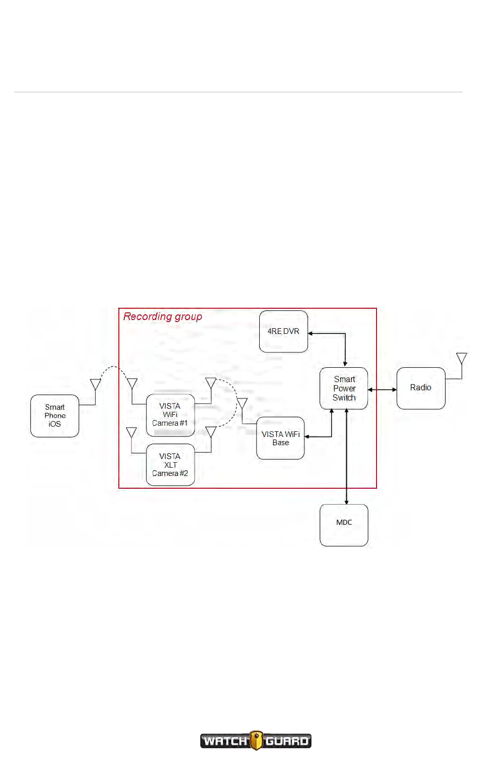
Recording groups
Recording groups
A recording group consists of a network of devices communicating with each other whenever
one of them changes its recording status. A recording group is typically linked to a vehicle.
Members of the recording group
A local recording group includes the following members, joined together with either wired or
wireless connections:
lSmart Power Switch (page 82)
l4RE DVR, firmware version of 4.0 or later (page 82)
lVISTA WiFi Base (page 83)
lOne or more VISTA WiFi or VISTA XLT cameras (page 84)
For information about installing the equipment for the recording group in a vehicle, see the 4RE
Vehicle Installation Instructions.
VISTA Body Camera
WGD00120 Revision
ReviewDraft_111518
81

Using VISTAWiFi or VISTA XLT with a Recording Group
Smart Power Switch
As part of the local recording group network, the Smart Power Switch:
lFunctions as the central connection point
The Smart Power Switch functions as the central wired connection point for a recording group.
Through the switch, the devices connect together to form a network, allowing the 4RE and
VISTA WiFi group members to communicate with each other.
lIntelligently manages power
The switch connects to the power source (for example, the vehicle battery) and intelligently
manages that power within the local recording group network. The Smart Power Switch can
detect the status of the devices in the network, whether they are powered on or have powered
themselves off after finishing event upload or charging. When the switch detects that the
devices in the local recording group network no longer need power, it shuts down any
remaining devices connected to the local network, including itself.
lFunctions as the local network DHCP server
The Smart Power Switch can also function as the DHCPserver for the local recording group
network and other devices connected to it (for example, wireless radio).
The Smart Power Switch is REQUIRED to form a recording group. There can only be one Smart
Power Switch in a recording group.
4RE DVR
Note: The 4RE DVR must be at firmware version 4.0 or later to participate in a
recording group.
As part of the local recording group network, the 4RE DVR:
lInitiates group recordings
The 4RE uses the recording group network to inform the other group members when it starts a
recorded event. The other group members can then join in the group recording by starting their
own recorded events.
For more information on group recordings, see Group recordings on page 85.
lStops group recordings
The 4RE uses the recording group network to inform the other group members when it stops a
recorded event. The other group members can then stop their own recorded events.
Only the 4RE DVR can stop a group recording. The other group members can stop their own
individual recorded events; but, only the 4RE can stop all of the members' recorded events that
are part of the group recording at the same time.
lResponds to group-recording starts by other group members
Through the recording group network, the 4RE is informed by other group members when they
start recorded events. 4RE can then join the group recording by starting its own recorded
event.
82
VISTA Body Camera
WGD00120 Revision
ReviewDraft_111518

VISTA WiFi Base
lPasses on its event categorization to other members' recorded events in the group recording
The category you assign on the 4RE to a recorded event that is part of a group recording is
passed on to other group members' recorded events that are part of the same group recording.
The other group members can choose to categorize their own recorded events, overriding any
category passed to them by the 4RE.
The 4RE DVR connects to the recording group network with a wired connection into the Smart
Power Switch. It also connects (wired connection) to the power source (vehicle battery).
The 4RE DVR is REQUIRED to form a recording group. There can only be one 4RE DVR in a
recording group.
For more information about the 4RE DVR, see the 4RE In-Car Video User Guide.
VISTA WiFi Base
As part of the local recording group network, the VISTA WiFi Base:
lPairs with VISTA WiFi or VISTA XLT
When you dock VISTA WiFi or VISTA XLT in the VISTA WiFi Base, the camera pairs with the
base. The pairing associates the camera with the local recording group.
For more information about docking VISTA WiFi or VISTA XLT in a WiFi Base, see Docking the
VISTABody Camera in a WiFi Base on page 34.
lActs as a Wi-Fi® access point (hotspot) to VISTA WiFi or VISTA XLT
The VISTA WiFi Base acts as an 802.11n Wi-Fi hotspot for VISTA WiFi or VISTA XLT cameras
that have paired with it.
lNotifies the recording group that a VISTA WiFi or VISTA XLT camera has started a recorded
event
The WiFi Base uses the recording group network to notify the other group members when one
of its paired VISTA WiFi or VISTA XLT cameras has started a recorded event.
lNotifies VISTA WiFi or VISTA XLT that a group recording has started or stopped
Through the recording group network, the WiFi Base is notified by other group members when
they start or stop a group recording. The base then notifies VISTA WiFi or VISTA XLT, and the
camera can start or stop its own recorded event with the recording group.
For more information on group recordings, see Group recordings on page 85.
The VISTA WiFi Base connects to the recording group network with a wired connection into the
Smart Power Switch. It also connects (wired connection) to a windshield antenna that allows it
to connect wirelessly with VISTA WiFi or VISTA XLT.
The VISTA WiFi Base is REQUIREDto form a recording group. There can only be one VISTA WiFi
Base in a recording group.
For more information about the VISTA WiFi Base, see VISTA WiFi Base on page 66.
VISTA Body Camera
WGD00120 Revision
ReviewDraft_111518
83

Using VISTAWiFi or VISTA XLT with a Recording Group
VISTA WiFi and VISTA XLT
As part of the local recording group network, the VISTA WiFi or VISTA XLT camera:
lPairs with the VISTA WiFi Base
When you dock VISTA WiFi or VISTA XLT in the VISTA WiFi Base, the camera pairs with the
base. The pairing associates the camera with the local recording group.
For more information about docking VISTA WiFi or VISTA XLT in a WiFi Base, see Docking the
VISTABody Camera in a WiFi Base on page 34.
lInitiates group recordings
VISTA WiFi or VISTA XLT notifies the WiFi Base that it has started a recorded event. The WiFi
Base then uses the recording group network to notify the other group members that VISTA
WiFi or VISTA XLT has started an event. The other group members can then join in the group
recording by starting their own recorded events.
For more information on group recordings, see Group recordings on page 85.
lResponds to group-recording starts or stops by other group members
Through the recording group network, the WiFi Base is notified by other group members when
they start or stop a group recording. The base then notifies VISTA WiFi or VISTA XLT, and the
camera can start or stop its own recorded event with the recording group.
Tip: If the 4RE DVR and VISTA WiFi or VISTA XLT are members of the
same recording group, you can use the 4RE to control VISTA WiFi or
VISTA XLT's recorded event starts, stops, and categorizations. In this
case, VISTA WiFi or VISTA XLT functions like another camera connected
to the 4REDVR.
VISTA WiFi or VISTA XLT connects to the recording group network with a wireless connection to
the VISTA WiFi Base.
Important! If VISTA WiFi or VISTA XLT has moved out of range of its associated
recording group network, it does not receive notifications of group recording
starts and stops until it is back in range. VISTA WiFi or VISTA XLT does not receive
any 4RE event categorization notifications that are sent while it is out of range.
For more information, see VISTA WiFi and VISTA XLT behavior during a group
recording on page 86.
VISTA WiFi or VISTA XLT can also provide a wireless access point (hotspot) for the
VISTASmartConnect smartphone application. For information about connecting the VISTA
SmartConnect application with VISTA WiFi, see Appendix A: Using VISTA SmartConnect on
page 89.
There can be multiple VISTA WiFi or VISTA XLT cameras in a recording group.
84
VISTA Body Camera
WGD00120 Revision
ReviewDraft_111518

Other devices in the system
Other devices in the system
lRadio
If present in the system, the wireless radio connects to the Smart Power Switch.
The 4RE DVR and VISTA WiFi or VISTA XLT (through the VISTA WiFi Base) can use the radio to
interact with Evidence Library 4 Web (EL4 Web) through an agency network access point. The
connection between the wireless radio and the agency network (EL4 Web) is independent of
the local recording group network.
lMDC/laptop
If present in the system, the MDC (mobile data computer) or other laptop computer connects
to the Smart Power Switch.
The computer only connects into the system through the Smart Power Switch; it is not
powered through the switch. If the computer is configured to be a DHCP client, it can also get
its network address from the Smart Power Switch.
lVISTA SmartConnect smartphone application
If present in the system, SmartConnect connects wirelessly to VISTA WiFi. VISTA WiFi acts as
an 802.11n Wi-Fi access point (hotspot) for the smartphone.
For information about connecting the VISTA SmartConnect application to VISTA WiFi, see
Appendix A: Using VISTA SmartConnect on page 89.
Group recordings
When 4RE and VISTA WiFi or VISTA XLT are associated with each other in a recording group,
the devices collaborate to start and stop their recorded events together. This collaboration
creates a group recording: multiple devices in the same recording group creating individual
recorded events of the same incident. Combined into the group recording, the individual events
from different perspectives create a more comprehensive view of the incident.
For more information on recording groups and individual group members, see Recording groups
on page 81.
When you upload a group recording to your Evidence Library software, the individual events are
automatically linked together as a group recording. When you play back the events from the
group recording, your Evidence Library software can play back one or more of them
synchronized in time. For example, you can play back video from the 4RE DVR while hearing
the audio from one of the VISTA WiFi cameras in the group.
For information about synchronized playback of group recordings, see your Evidence Library
software documentation.
VISTA Body Camera
WGD00120 Revision
ReviewDraft_111518
85

Using VISTAWiFi or VISTA XLT with a Recording Group
VISTA WiFi and VISTA XLT behavior during a group recording
Any DVR device (4RE, VISTA WiFi, or VISTA XLT) in the recording group can start a recorded
event. The other DVR devices in the group are informed of that change in recording status, so
they can join in the group recording.
For more information on the VISTA WiFi or VISTA XLT camera's role in a recording group, see
VISTA WiFi and VISTA XLT on page 84.
What happens when:
lYou try to manually start a recorded event on VISTA WiFi or VISTA XLT just after it has
automatically started an event as part of a group recording?
If you have pressed the Record Start/Stop button within 10 seconds of the automatic group
recording start, VISTA WiFi or VISTA XLT asks you to confirm that you want to STOP the
recorded event with your Record Start/Stop button press. If you do not press the Record
Start/Stop button again within 5 seconds, the camera continues recording the event as part
of the group recording.
If you press the button a second time within 5 seconds, the camera stops recording the event.
Because VISTA WiFi and VISTA XLT connect to the recording group with a Wi-Fi connection
(through the WiFi Base), VISTA WiFi and VISTA XLT can move into and out of the recording
group range.
What happens when:
lThe VISTA WiFi or VISTA XLT that INITIATED the group recording moves out of range during
the group recording?
All the devices in the recording group keep recording until the 4RE stops the group recording or
each individual member stops its own event. The initiating device moving out of range does not
affect the other devices' ability to start, stop, and categorize their own events.
The VISTA WiFi or VISTA XLT that went out of range keeps recording the event until it is
manually stopped. A device moving out of range does not affect its ability to start, stop, and
categorize its own events.
lA VISTA WiFi or VISTA XLT that is part of a group recording moves out of range during the group
recording?
The VISTA WiFi or VISTA XLT keeps recording the event until it is manually stopped. A device
moving out of range does not affect its ability to start, stop, and categorize its own events.
lThe group recording is stopped while a VISTA WiFi or VISTA XLT that is part of that group
recording is out of range?
The out-of-range VISTA WiFi or VISTA XLT keeps recording the event until it is manually
stopped OR moves back into range of the group network.
When the VISTA WiFi or VISTA XLT that is still recording moves back into range, it is informed
that its associated group has stopped the group recording. It then stops its own event.
lA VISTA WiFi or VISTA XLT that is not currently recording an event walks into range of an
associated recording group network during a group recording?
When the VISTA WiFi or VISTA XLT moves into range, it is informed that its associated group
has started a group recording. It then begins its own event to join the group recording.
86
VISTA Body Camera
WGD00120 Revision
ReviewDraft_111518

VISTA WiFi and VISTA XLT behavior during a group recording
lA VISTA WiFi or VISTA XLT that is currently recording an event walks into range of an associated
recording group network that is NOT in a group recording?
When the VISTA WiFi or VISTA XLT moves into range, it informs its associated group that it is
recording an event. The other devices in the group begin their own events to create a group
recording.
For more information about...
Docking VISTA WiFi or VISTA XLT in the VISTA WiFi Base, see Docking the VISTABody Camera
in a WiFi Base on page 34.
Associating VISTA WiFi or VISTA XLT with a recording group, see VISTA WiFi and VISTAXLT:
Associating with a recording group on page 44.
Installing VISTA WiFi or VISTA XLT equipment in the vehicle, see the 4RE Vehicle Installation
Instructions.
VISTA Body Camera
WGD00120 Revision
ReviewDraft_111518
87

88
VISTA Body Camera
WGD00120 Revision
ReviewDraft_111518
Using VISTAWiFi or VISTA XLT with a Recording Group
This page intentionally left blank.

Appendix A: Using VISTA SmartConnect
Appendix A: Using VISTA SmartConnect
In this section...
lSmartConnect Overview (page 90)
lConnecting VISTA WiFi or VISTA XLT to VISTA SmartConnect (page 94)
lReviewing recorded event video (page 98)
lCategorizing recorded events (page 99)
lLive streaming the current VISTA view (page 101)
lStarting and stopping recorded events (page 102)
lSmartConnect settings (page 104)
VISTA Body Camera
WGD00120 Revision
ReviewDraft_111518
89

Appendix A: Using VISTA SmartConnect
SmartConnect Overview
Note: The Wi-Fi® version of VISTA® and VISTA XLT™ can connect to the VISTA
SmartConnect smartphone application.
VISTA WiFi and VISTA XLT can serve as a hotspot for the VISTA SmartConnect smartphone
application. Set up the camera-to-smartphone Wi-Fi connection credentials when you check
out your VISTA WiFi or VISTA XLT camera from your Evidence Library software. See Connecting
to VISTA SmartConnect on page 94.
The VISTA SmartConnect app makes VISTA WiFi and VISTA XLT functionality available on your
smartphone:
lReview recorded events (page 98)
lCategorize recorded events (page 99)
lLive stream the camera view (page 101)
lStart and stop recorded events (page 102)
You can adjust your camera LEDs or alert levels, enable Covert Mode, or view data about your
camera. (page 104)
Warning! No evidence videos are stored on the smartphone. Snapshots stored
on the phone make it subject to being confiscated as evidence. You can configure
your Evidence Library software to disable the snapshot feature.
90
VISTA Body Camera
WGD00120 Revision
ReviewDraft_111518
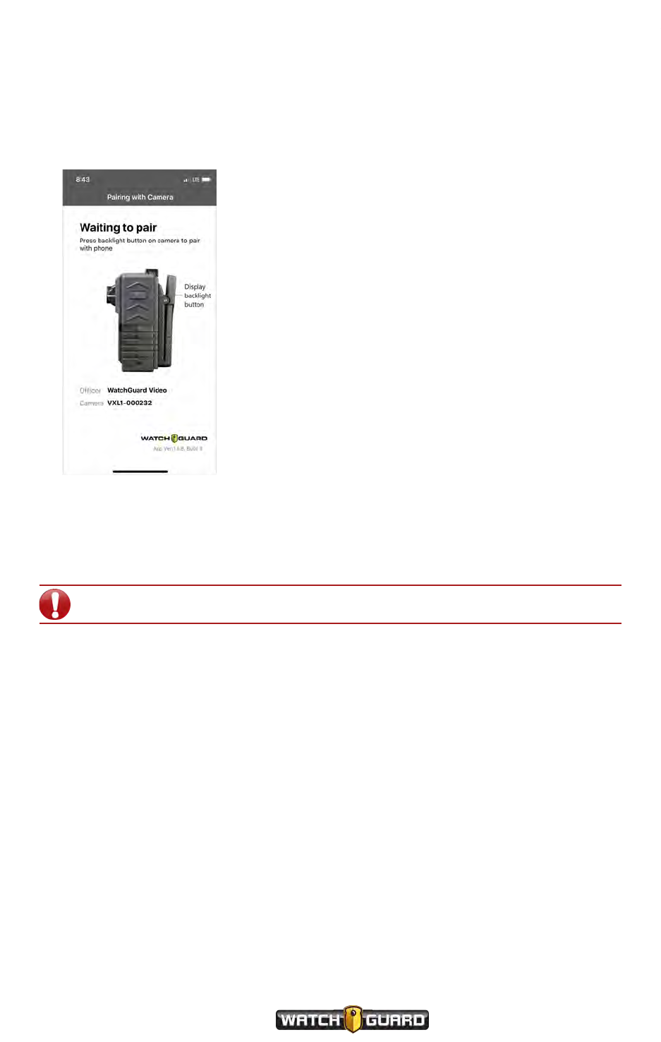
Activating the VISTA WiFi or VISTA XLT hotspot
Activating the VISTA WiFi or VISTA XLT hotspot
You must activate the VISTA WiFi or VISTA XLT hotspot to connect the camera with
SmartConnect. To activate the hotspot:
1. Press the Display Backlight button on the camera.
Two ascending tones sound (depending on the alert configuration settings).
2. Connect the SmartConnect app to the VISTA WiFi or VISTA XLT hotspot within two minutes or
the hotspot deactivates.
Two descending tones sound when the hotspot deactivates.
Important! Start the hotspot before starting the SmartConnect application.
VISTA Body Camera
WGD00120 Revision
ReviewDraft_111518
91
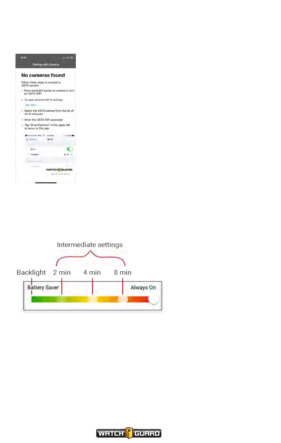
Appendix A: Using VISTA SmartConnect
No cameras found
If no camera is found, follow the instructions on the screen.
Controlling battery usage
How you set your hotspot settings gives you control over your battery usage and hotspot
connection time. You can choose one of the settings shown here for your VISTA WiFi or VISTA
XLT.
Battery Saver uses the least battery power. Push the Display Backlight button on the
camera to start the hotspot.
lIf the Wi-Fi client does not attach, the hotspot waits for 2 minutes, then shuts down.
lIf a Wi-Fi client attaches, the hotspot stays on for another 2 minutes waiting for the
SmartConnect app to connect. If the app does not connect, the hotspot shuts down.
92
VISTA Body Camera
WGD00120 Revision
ReviewDraft_111518

Disconnecting SmartConnect
Intermediate settings—2, 4, or 8 minutes. These settings activate the hotspot on a
record-stop, waiting for initial app connect.
lIf the app does not connect within the time frame based on your slider position, the hotspot
shuts down.
lThe camera is not allowed to sleep during the wait period.
Always On uses the most battery power but activates when the camera is off the dock and not
in sleep mode.
lOn undock, boot, or reboot there is a 10 second wait to activate the hotspot.
lWhen coming out of sleep mode, the hotspot restarts immediately.
Disconnecting SmartConnect
Standard disconnect
The below scenario describes a standard disconnect which happens when the app is:
lClosed
lPut in the background
lThe phone goes to sleep
After the app connects, the hotspot remains on for as long as the app is connected. The camera
cannot enter sleep mode, even if configured to do so. The hotspot waits a full minute to shut
down after the app is disconnected. This lets you get back into the app quickly without having to
re-establish the Wi-Fi connection.
Nonstandard disconnect
The below scenario describes a nonstandard disconnect such as:
lYou walk out of range
lThe Wi-Fi is turned off
lThe app disconnects on it own
If no explicit disconnect occurs, the camera continues to search for activity for 1 minute. After
this time, VISTA WiFi or VISTA XLT starts a 1-minute grace period and then stops the hotspot.
This gives you 2 minutes to reconnect if a nonstandard disconnect occurs.
VISTA Body Camera
WGD00120 Revision
ReviewDraft_111518
93

Appendix A: Using VISTA SmartConnect
Connecting to VISTA SmartConnect
At VISTA WiFi or VISTA XLT checkout, your Evidence Library software assigns you an SSID and
you create a password. You enter this SSID/password combination in the Wi-Fi settings on your
smartphone to connect the SmartConnect app with the camera. For information on getting
your SSID/password combination at VISTA WiFi or VISTA XLT checkout, see your Evidence
Library software documentation.
You only enter the SSID and password the first time you connect VISTA WiFi or VISTA XLT
with the SmartConnect application.
Important! If you change the password associated with your SSID, you must
use the steps to connect camera with SmartConnect for the first time (below).
Connecting VISTA WiFi or VISTA XLT to SmartConnect for the
first time
Before you start the connection process, you need:
lChecked-out VISTA WiFi or VISTA XLT, powered ON
lSmartphone, powered ON
lThe SSID and password that your Evidence Library software assigned to you
Important! You must turn on the hotspot before starting the application (page
90).
94
VISTA Body Camera
WGD00120 Revision
ReviewDraft_111518
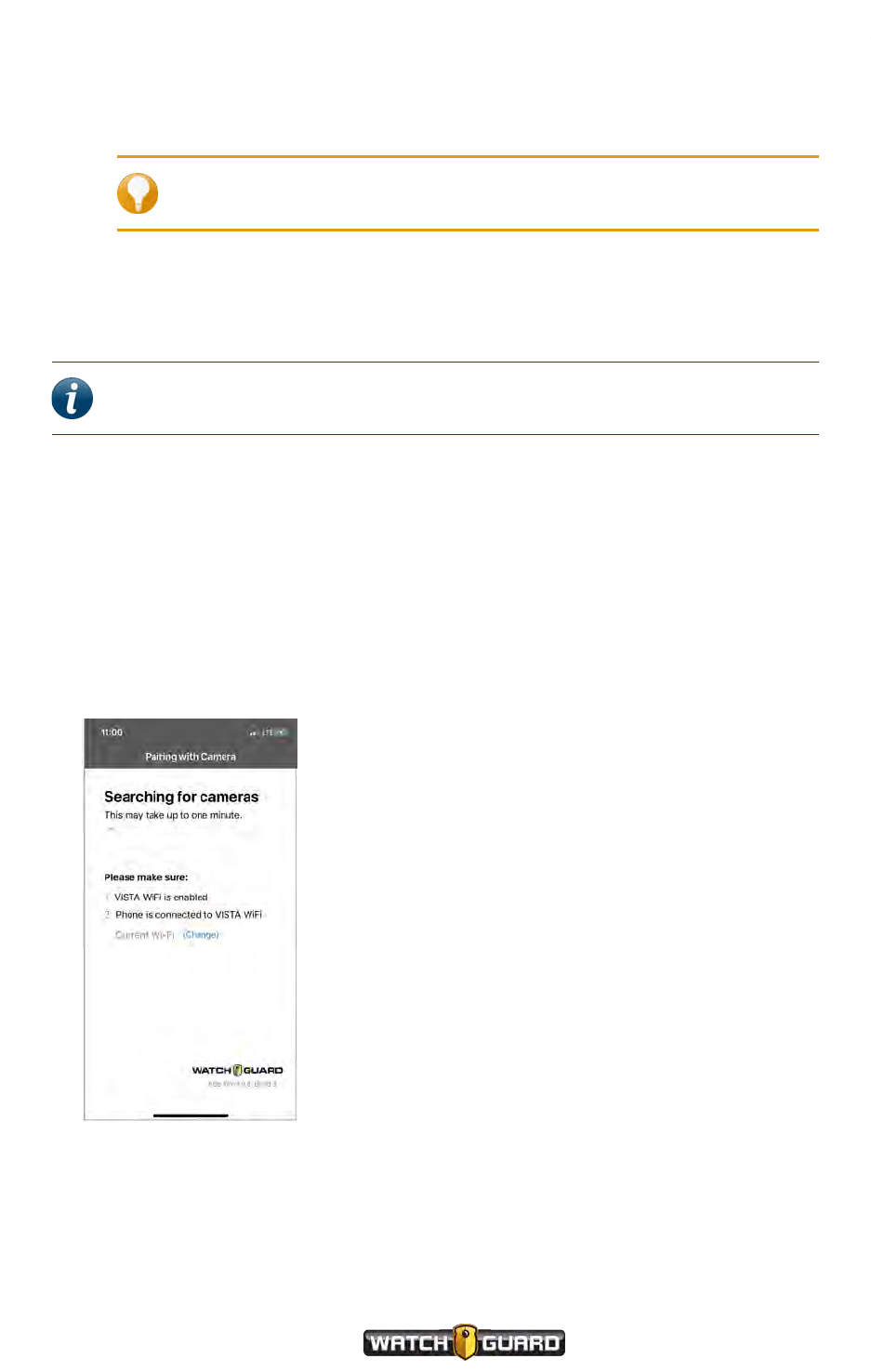
Connecting VISTA WiFi or VISTA XLT to SmartConnect for the first time
To connect VISTA WiFi or VISTA XLT with VISTA SmartConnect for the first time:
1. Download VISTA SmartConnect to your smartphone from the app Store.
Tip: For best results, do not open the VISTA SmartConnect app until
instructed to open it.
2. Navigate to Settings >Wi-Fi > Other.
3. Enter the SSID that Evidence Library assigned to you at checkout.
4. Select WPA2 as your security level.
Note: If you have a choice between WPA2 Personal and WPA2 Enterprise, select
WPA2 Personal.
5. Go back to Other network screen.
6. Enter the Password you created when you checked out your VISTA WiFi camera. Do not press
the Join button.
7. Press the Display Backlight button on your VISTA WiFi to turn on the hotspot.
Two ascending tones sound (depending on the VISTA WiFi alert configuration settings).
8. Press Join on the top right.
9. Press the SmartConnect app icon.
The app presents the Searching for cameras screen while trying to find a camera to
connect to.
VISTA Body Camera
WGD00120 Revision
ReviewDraft_111518
95
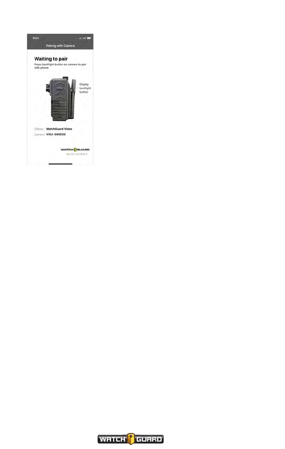
Appendix A: Using VISTA SmartConnect
10. Press the Display Backlight button to pair the app with the camera.
The Recorded Events screen opens after pairing is complete and shows a list of events available
on your VISTA WiFi or VISTA XLT.
96
VISTA Body Camera
WGD00120 Revision
ReviewDraft_111518
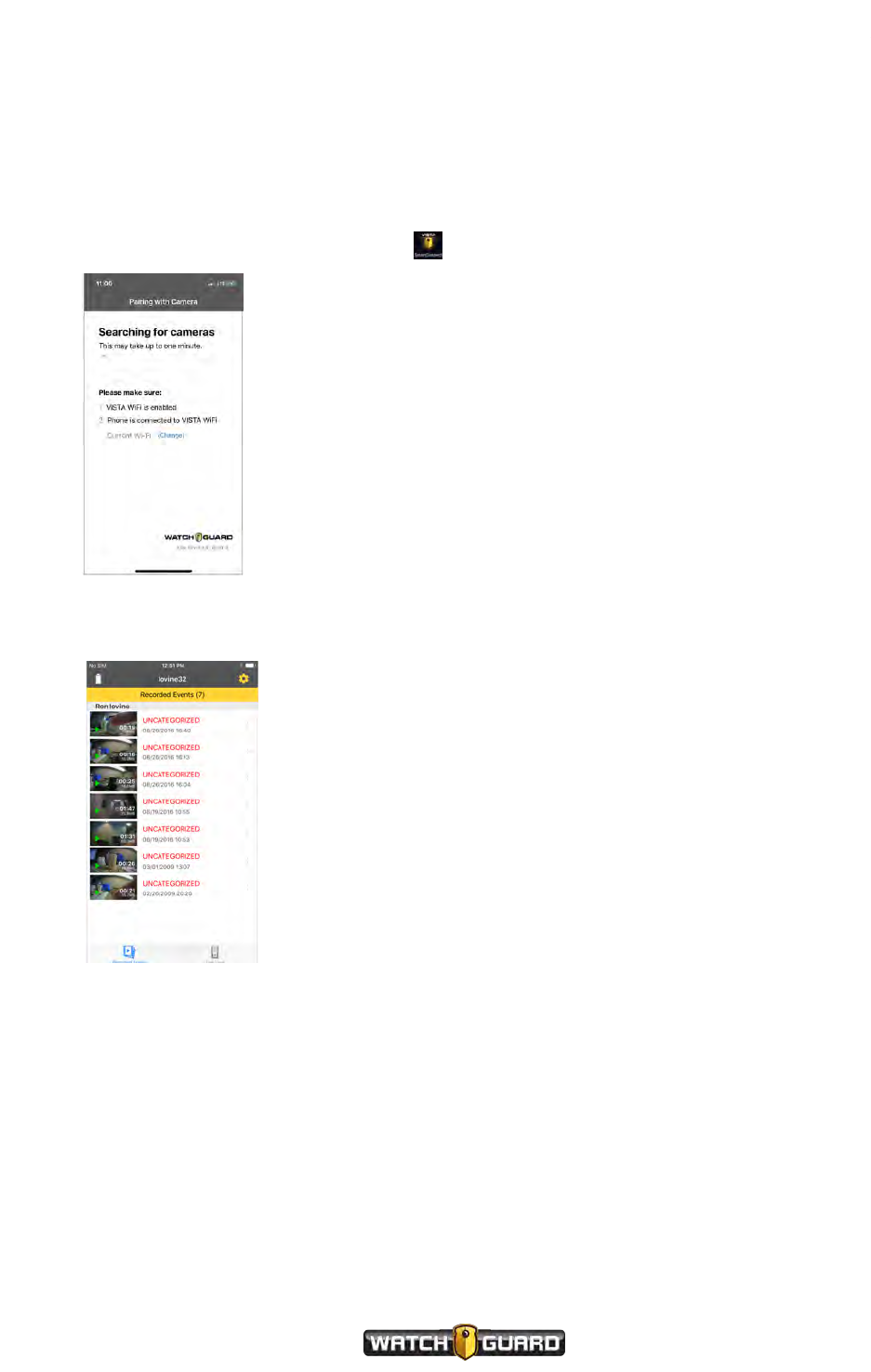
Connecting VISTA WiFi or VISTA XLT to SmartConnect after the first time
Connecting VISTA WiFi or VISTA XLT to SmartConnect after
the first time
To connect VISTA WiFi or VISTA XLT with VISTA SmartConnect after the first time:
1. Press the camera Display Backlight button to activate the hotspot. (page 89)
2. Open the VISTA SmartConnect app icon.
The Pairing with Camera screen opens while the app is searching for the camera to connect
with. After it finds the camera, the Recorded Events screen opens showing a list of events on
your camera.
VISTA Body Camera
WGD00120 Revision
ReviewDraft_111518
97
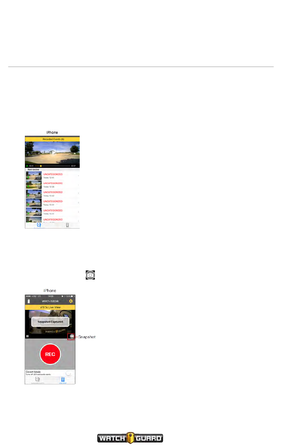
Appendix A: Using VISTA SmartConnect
Reviewing VISTAWiFi or VISTA XLT Recorded
Events
You can review recorded event video from your VISTA WiFi or VISTA XLT camera on the
smartphone application.
After you connect and the event screen appears:
nTouch the thumbnail for the video event you want to review.
The event starts playing back.
Capturing snapshots
If snapshots are enabled for SmartConnect in your Evidence Library software:
nTouch the camera icon to save a snapshot of the current frame to the phone photo gallery.
98
VISTA Body Camera
WGD00120 Revision
ReviewDraft_111518
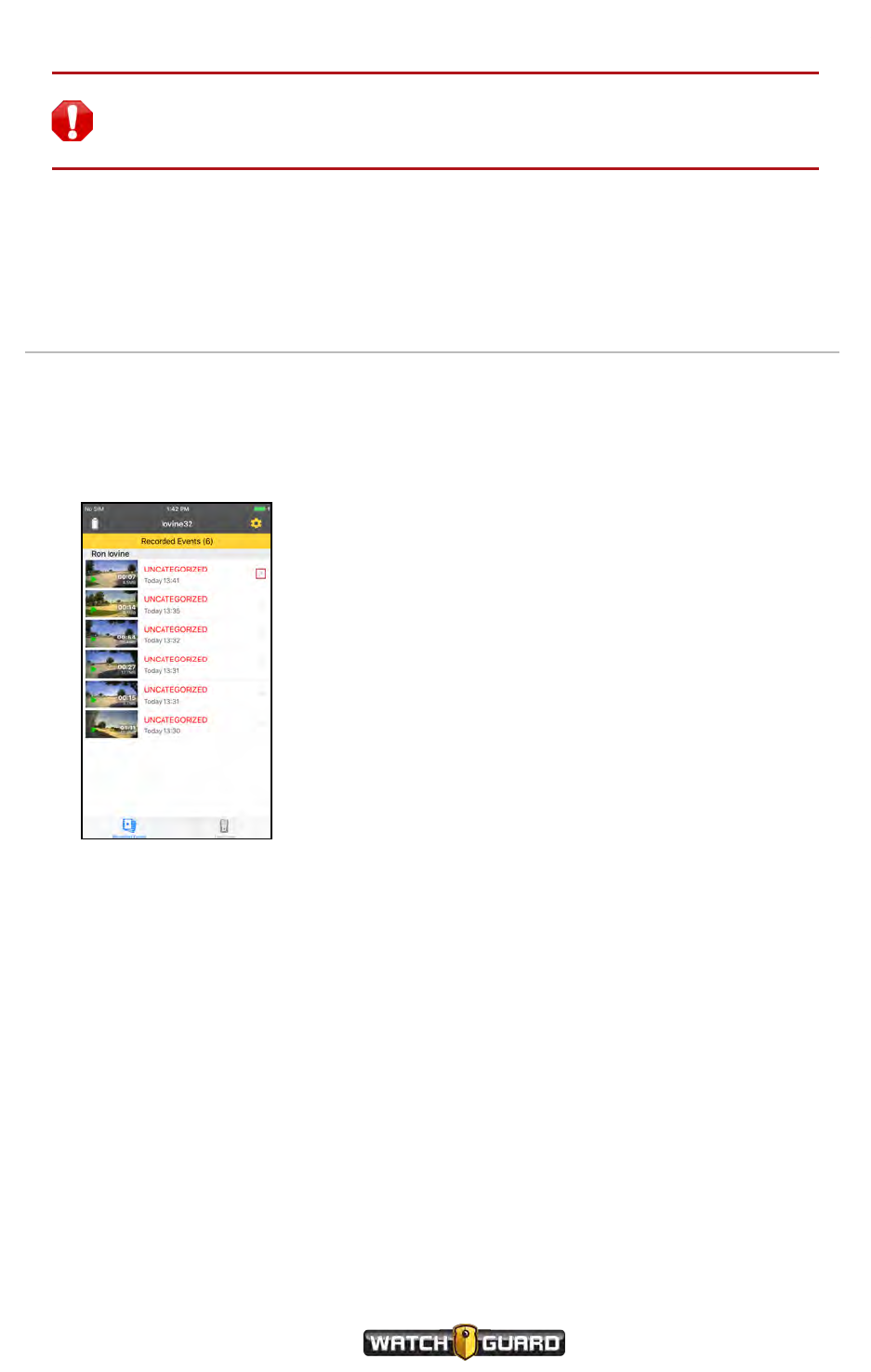
Categorizing Recorded Events
Warning! Capturing snapshots of video from the VISTASmartConnect app and
saving them to the smartphone photo gallery can make the phone part of the
chain of evidence.
If you did not accept saving your snapshot files when you first connected to SmartConnect, the
app will ask at this point. If you select Deny, you will not be able to save snapshots.
Categorizing Recorded Events
You can use the VISTA SmartConnect smartphone application to categorize a recorded event
on your VISTA camera.
After the Recorded Events screen opens follow the steps for your smart phone.
VISTA Body Camera
WGD00120 Revision
ReviewDraft_111518
99
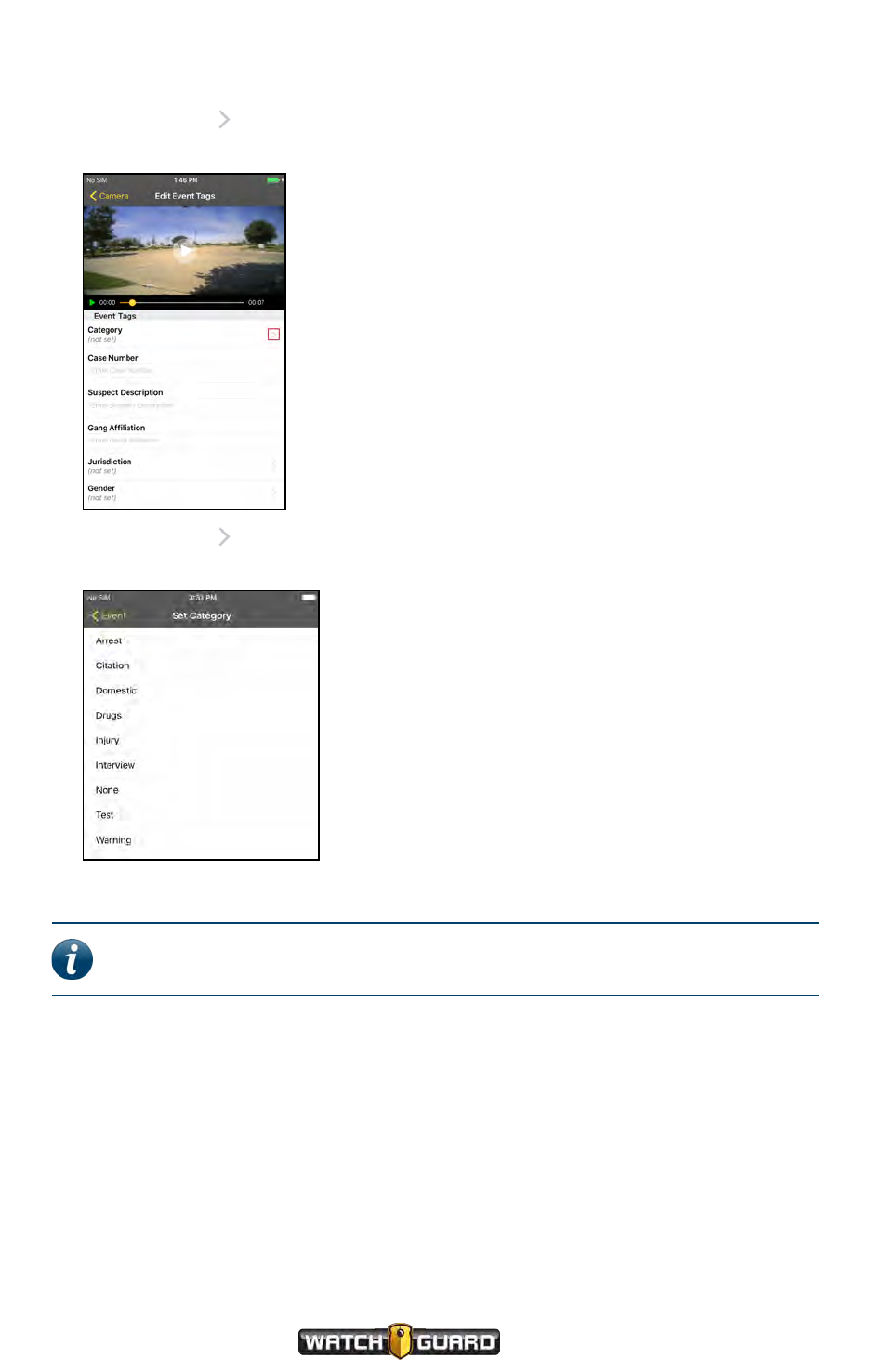
Appendix A: Using VISTA SmartConnect
To categorize an event:
1. Touch the arrow for the event that you want to categorize.
The Edit Event Tags screen opens for the event you selected.
2. Touch the arrow for the Category event tag.
The Set Category screen opens.
3. Touch the category you want to apply to the recorded event.
Note: If there are secondary event tags assigned to your VISTA WiFi or VISTA
XLT configuration, those tags appear after you select the category.
100
VISTA Body Camera
WGD00120 Revision
ReviewDraft_111518
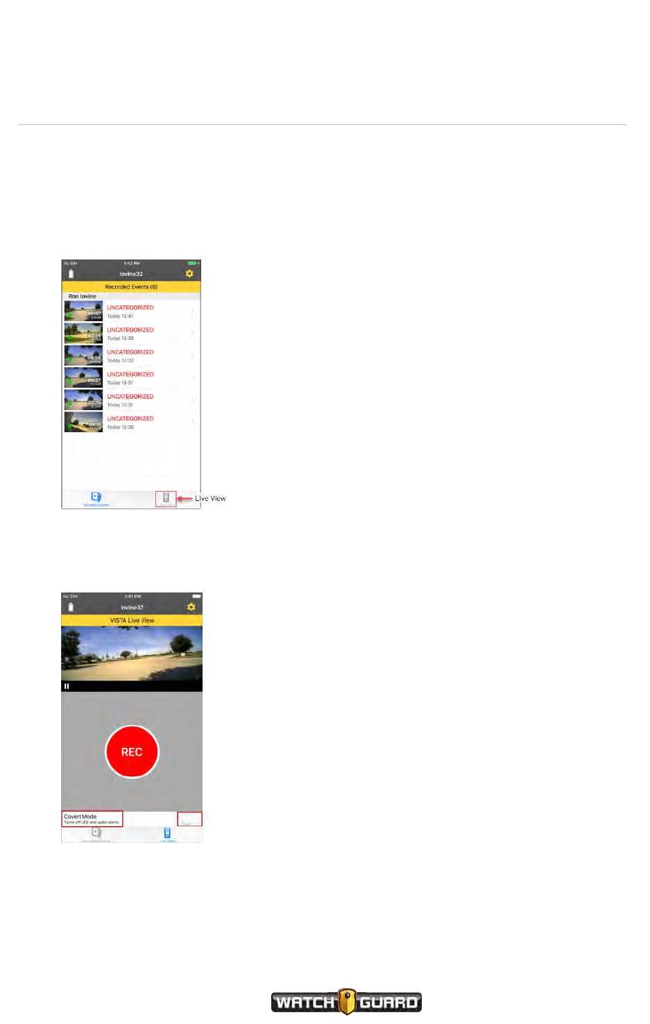
Live Streaming
Live Streaming
You can live stream the view from your VISTA WiFi or VISTA XLT camera with the VISTA
SmartConnect smartphone application.
1. Connect your VISTA WiFi or VISTA XLT to VISTA SmartConnect on your smartphone. (page
94)
The Recorded Events screen opens.
2. Touch Live View.
The VISTA Live View screen opens showing an inactive player.
3. Touch the play icon to start live streaming from the camera.
VISTA Body Camera
WGD00120 Revision
ReviewDraft_111518
101
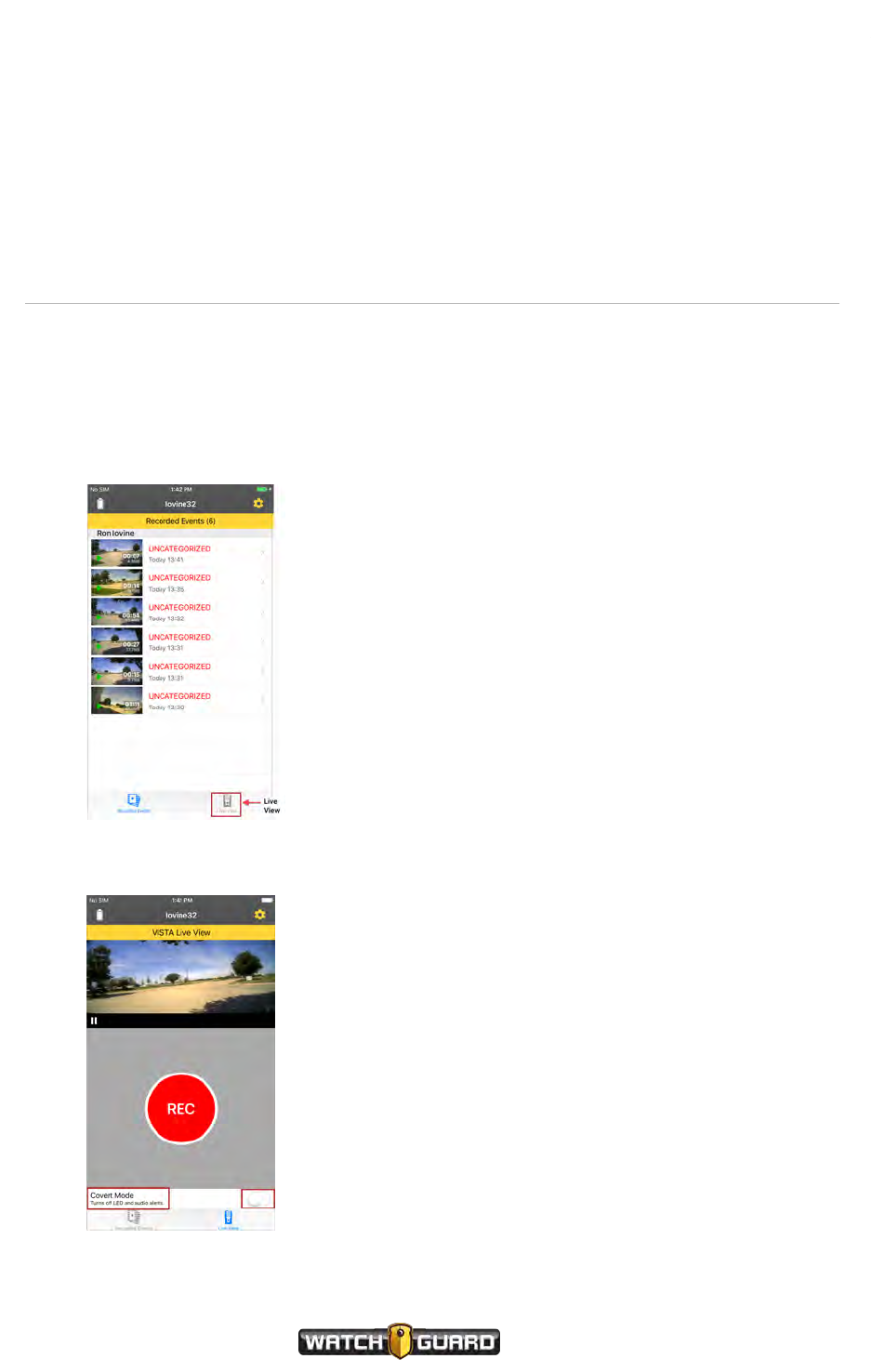
Appendix A: Using VISTA SmartConnect
Covert Mode
Enable Covert Mode on the VISTA Live View screen.
nTouch or slide the Covert Mode switch until the background changes color.
Starting and Stopping Recorded Events
You can start or stop a recorded event on your VISTA WiFi or VISTA XLT camera with the
smartphone application:
1. Connect your VISTA WiFi or VISTA XLT to VISTA SmartConnect on your smartphone. (page
94)
The Recorded Events screen opens.
2. Touch the Live View icon.
The VISTA Live View screen opens.
102
VISTA Body Camera
WGD00120 Revision
ReviewDraft_111518

Starting and Stopping Recorded Events
3. Touch REC to start recording an event.
The camera starts recording. SmartConnect shows that the camera is recording with the red
bar at the top of the app on the iPhone.
4. Touch STOP to stop recording an event.
VISTA Body Camera
WGD00120 Revision
ReviewDraft_111518
103
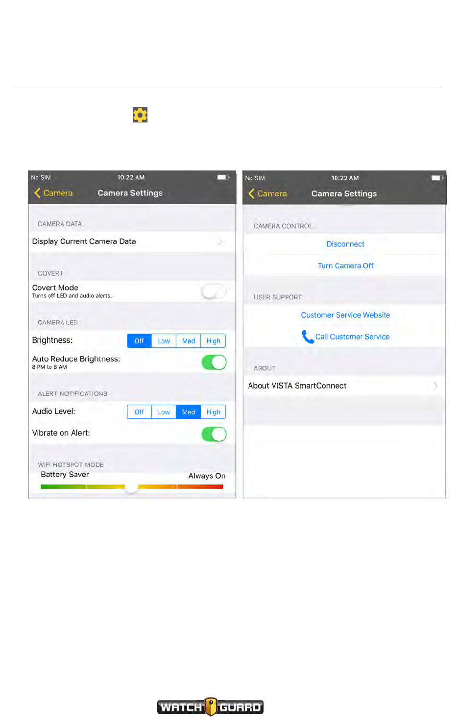
Appendix A: Using VISTA SmartConnect
SmartConnect Settings
Touch the Settings icon to access the SmartConnect Camera Settings screens.
Camera Settings
104
VISTA Body Camera
WGD00120 Revision
ReviewDraft_111518
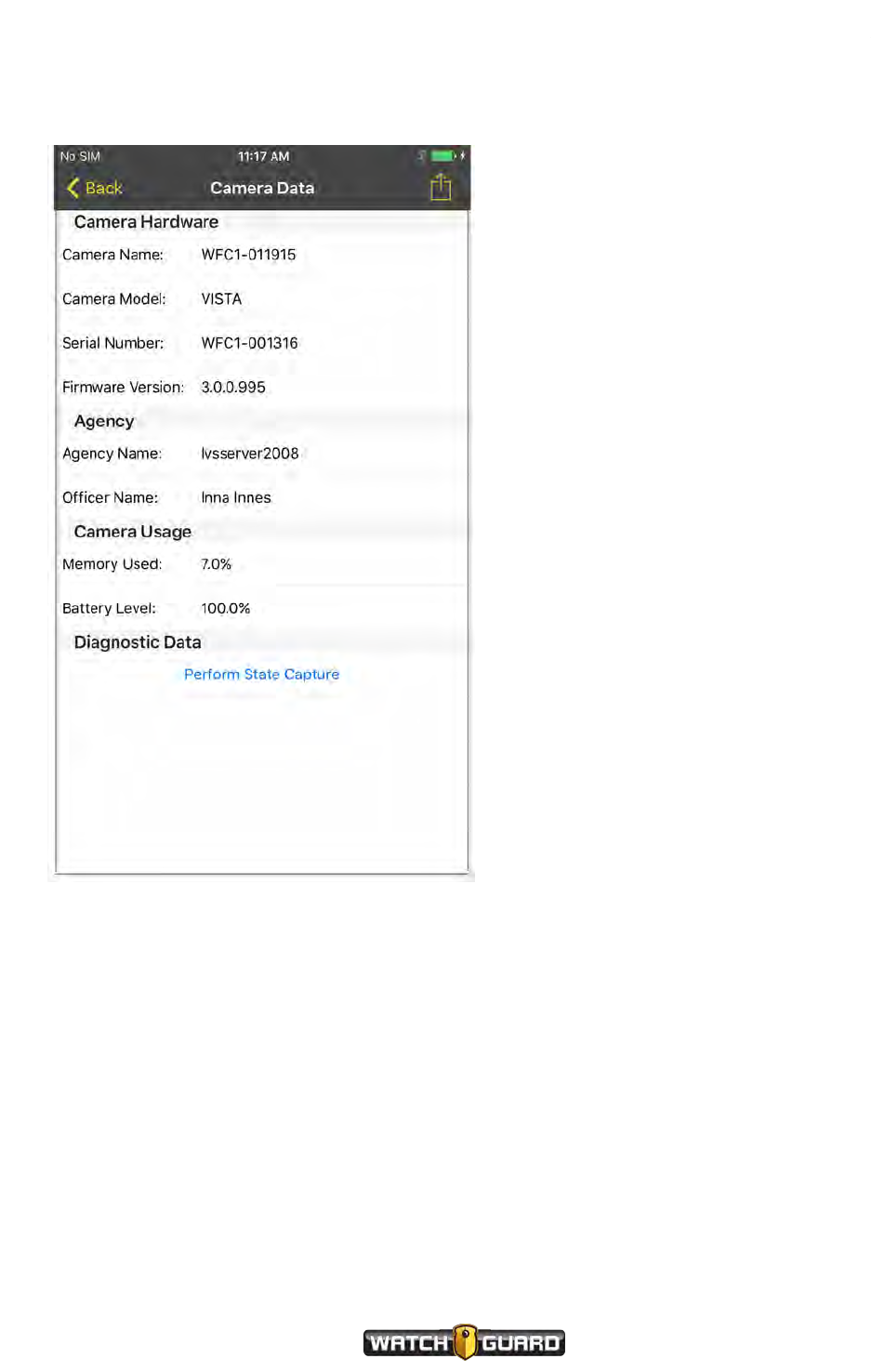
Camera Data
Camera Data
You can request that your VISTA WiFi or VISTA XLT perform a state capture and save it for use
by WatchGuard Technical Services.
VISTA Body Camera
WGD00120 Revision
ReviewDraft_111518
105

106
VISTA Body Camera
WGD00120 Revision
ReviewDraft_111518
Appendix A: Using VISTA SmartConnect
This page intentionally left blank.

Appendix B: Using the Quick Connect Mobile Charger
Appendix B: Using the Quick Connect Mobile
Charger
In this section...
lQuick Connect Mobile Charger overview (page 108)
lMobile Charger parts (page 108)
lUsing the Mobile Charger (page 111)
Warning! The Quick Connect Mobile Charger uses magnets to connect to the
cable. Do not wear the Mobile Charger near sensitive medical equipment or
implants such as pacemakers or other magnetically programmable medical
devices.
FCC Rules compliance
This device complies with Part 15 of the FCC Rules. Operation is subject to the following two
conditions:
1. This device may not cause harmful interference.
2. This device must accept any interference received, including interference that may cause
undesired operation.
VISTA Body Camera
WGD00120 Revision
ReviewDraft_111518
107
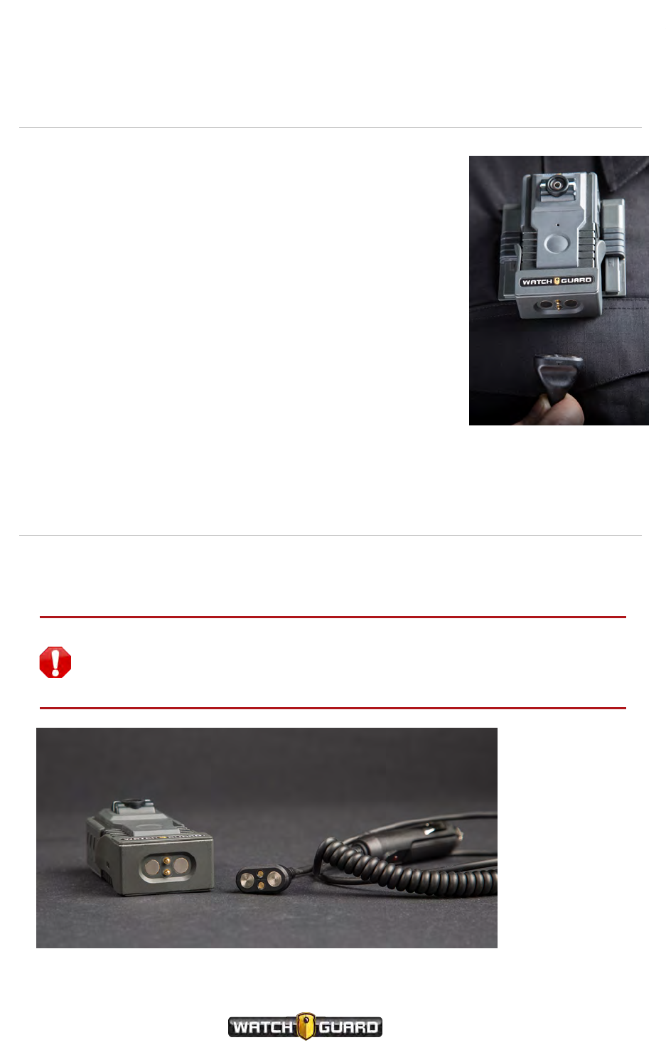
Appendix B: Using the Quick Connect Mobile Charger
Overview
The VISTA Quick Connect Mobile Charger lets recording and charging
occur at the same time. Information screens remain the same as if
the VISTA Body Camera is undocked and not charging. You do not
have to remove your camera to charge it.
The Mobile Charger works with extended-capacity VISTA and VISTA
WiFi running version 3.0 or higher. It is NOT supported for standard-
capacity VISTA or VISTA XLT.
The Mobile Charger lets you extend the working time of your VISTA
Body Camera when a 12-hour charge is not enough. Connecting or
disconnecting the Mobile Charger does not affect the running mode
of the VISTA Body Camera. Covert mode and the recording state are
preserved.
Mobile Charger Parts
The Quick Connect Mobile Charger consists of the base and the charging cable that are
connected with magnets.
Warning! The Quick Connect Mobile Charger uses magnets to connect to the
cable. Do not wear the Mobile Charger near sensitive medical equipment or
implants such as pacemakers or other magnetically programmable medical
devices.
108
VISTA Body Camera
WGD00120 Revision
ReviewDraft_111518
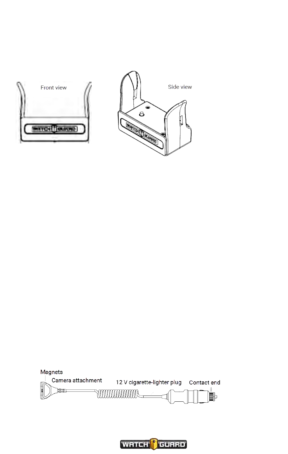
Mobile Charger base
Mobile Charger base
The VISTA Body Camera slips into the base with a click. Do not tilt the camera when inserting it.
Ensure that you insert the camera with the front of the camera facing the same way as the
WatchGuard logo on the front of the mobile charger.
To remove the VISTA Body Camera from the Mobile Charger:
1. Gently pull one wing of the charger base outward from the camera.
2. Rock or tilt the Mobile Charger base away from the camera.
Mobile Charger cable
The 12V cigarette-lighter plug for the mobile charger has a 3-amp fuse built in. This fuse may or
may not be higher than what your vehicle electrical panel is configured with. The cable has no
limiting mechanism so it will draw the maximum current the supply can provide if shorted.
This can cause the fuse to blow in the lighter plug of the cable or in the vehicle electrical
distribution box. If this happens:
1. Check your vehicle distribution box.
a. If the fuses are 3A or smaller, replace these before replacing the Mobile Charger cable fuse.
b. If the fuses are greater than 3A, replace the Mobile Charger cable fuse.
WatchGuard recommends the Littelfuse 312003P (part number WGP02649). This is a
250 V, 3A, Fast Acting Fuse. The fuse size is 3AG.
2. Replace the fuse in the Mobile Charger cigarette-lighter plug.
a. Grasp the lighter plug.
b. Unscrew the contact end.
The fuse comes out when you fully unscrew the end and pull it out.
c. Replace the existing fuse with a 3A fuse and reinsert it into the lighter plug.
VISTA Body Camera
WGD00120 Revision
ReviewDraft_111518
109
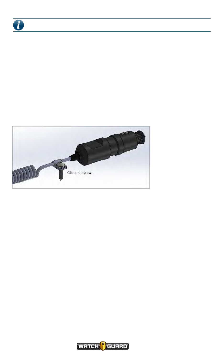
Appendix B: Using the Quick Connect Mobile Charger
Note: WatchGuard supports the US-type 12 V cigarette-lighter plug.
Cable connection end
The cable has magnets that align with the bottom of the Quick Connect Mobile Charger. They
are strong enough that they will not fall off of the base if you are moving around in the car or a
short distance from the car. They pull away easily from the base when you want to exit the car.
The charger works with the cable in any attachment orientation.
12 V cigarette-lighter plug
Some cigarette-lighter receptacles do not hold the plug tightly. You can use the clip (part
number WGP760-100) and screw (part number WGP635-002) to secure the cable to the
console as shown in the graphic. This prevents the cigarette-lighter plug from pulling out of the
receptacle when you pull on the cable. The clip and screw are shipped with the Quick Connect
Mobile Charger.
110
VISTA Body Camera
WGD00120 Revision
ReviewDraft_111518

Using the Mobile Charger
Using the Mobile Charger
The Mobile Charger charges itself through the vehicle cigarette lighter. Plug the cable into the
cigarette lighter receptacle, then attach the other end to the Mobile Charger.
Note: When turned off, some vehicles continue to supply 12 V power to the
cigarette-lighter receptacle. To avoid a possible dead battery, disconnect the
charger cable from the Mobile Charger.
When the Mobile Charger is connected, the VISTA Body Camera does not indicate on the display
or in the logs that the camera is docked. The camera successfully records, stops recording, and
acts according to its group recording configuration when it is connected to the Mobile Charger.
The camera has different notifications for different tasks, as shown in the table.
Actions Mode Notification
Connecting to
Mobile Charger
Non-Covert
- Ascending tones with vibration (depends on
agency configuration)
- Battery icon updates
- Does not affect running mode
Covert
- Vibration (depends on agency
configuration)
- Battery icon updates
- Does not affect running mode
Disconnecting from
Mobile Charger
Non-Covert
- Descending tones with vibration (depends
on agency configuration)
- Battery icon updates
Covert
- Vibration (depends on agency
configuration)
- Battery icon updates
Charging in Mobile
Charger
- Crawling battery icon then full battery icon
- CHARGE COMPLETE shows when finished
- Tone when complete (depends on agency
configuration)
- Solid green LED
- Does not indicate that it is connected
Although the camera backlight does not illuminate, you can turn it on by pushing the Display
Backlight button on the side of the camera. It also comes on when you start an event.
VISTA Body Camera
WGD00120 Revision
ReviewDraft_111518
111

112
VISTA Body Camera
WGD00120 Revision
ReviewDraft_111518
Appendix B: Using the Quick Connect Mobile Charger
This page intentionally left blank.

Appendix C: Upgrading VISTA, VISTAWiFi, and VISTA-Related Devices
Appendix C: Upgrading VISTA, VISTAWiFi,
and VISTA-Related Devices
This appendix contains information and instructions for:
lUpgrades to VISTA and VISTA WiFi that are different in some way from the standard upgrade
process (page 40)
lUpgrades to other devices related to VISTA or VISTA WiFi
Note: The upgrade instructions included in this appendix are in release-date
order. Each set of instructions stands on its own.
Upgrade instructions included in this appendix:
lUpgrading VISTA or VISTA WiFi to firmware version 2.2.0 (page 114)
lUpgrading the VISTA WiFi Base and the Smart Power Switch (page 115)
lUpgrading VISTA or VISTA WiFi from a pre-v2.0.2 firmware version (page 116)
VISTA Body Camera
WGD00120 Revision
ReviewDraft_111518
113
Appendix C: Upgrading VISTA, VISTAWiFi, and VISTA-Related Devices
Upgrading VISTA or VISTA WiFi to Firmware Version
2.2.0
Warning! VISTA and VISTA WiFi do NOTsupport downgrading from firmware
version 2.2.0 and above to a firmware version prior to 2.2.0.
To upgrade VISTA or VISTA WiFi to firmware version 2.2.0:
1. Dock the camera in a base or Transfer Station connected to your Evidence Library software.
The Evidence Library software automatically detects that the camera is docked and that its
firmware needs to be updated.
2. Using Evidence Library software, ensure the version 2.2.0 firmware is pushed to the camera.
Note: Evidence Library software can be set up to push firmware
manually or automatically.
The version 2.2.0 firmware is staged on the camera.
3. The next time you dock it, the VISTA or VISTA WiFi camera upgrades to the staged firmware
version 2.2.0.
4. WAIT while the camera upgrades its firmware.
While the camera is upgrading, the LCD Display shows UPDATINGDONOT INTERRUPT.
Warning! DO NOT REMOVE the camera from the dock while it upgrades
its firmware. Removing the camera from the dock while it upgrades can
cause the camera to stop functioning.
When it finishes upgrading, the camera sounds the camera ready alert (depending on your
alert notification selections).
5. The next time you undock the camera, it reboots itself.
While the camera is restarting, the LCD Display shows BOOTING.
6. When the camera finishes rebooting, you can use it normally.
Tip: After you have completed these upgrade instructions, if VISTA or VISTA
WiFi's LCD Display shows Err 30 or Err 120, contact WatchGuard Customer
Service.
114
VISTA Body Camera
WGD00120 Revision
ReviewDraft_111518
Upgrading the VISTA WiFi Base and the Smart Power Switch
Upgrading the VISTA WiFi Base and the Smart
Power Switch
When upgrades are available for the VISTA WiFi Base and the Smart Power Switch, the
upgrades are included with the VISTA Body Camera upgrade. Once the camera has been
upgraded, the next time it is docked in the WiFi Base, it makes the base and switch upgrade
packages available.
For information on upgrading the VISTA Body Camera, see Upgrading firmware on page 40.
Note: Typically, WatchGuard releases upgrades for the camera, the WiFi Base,
and the Smart Power Switch at the same time.
To upgrade the VISTA WiFi Base and the Smart Power Switch:
1. Dock the upgraded camera in the WiFi Base and allow it to pair with the base.
The base's left LED blinks green multiple times when the camera and base are paired.
2. WAIT while the camera stages any video it has stored.
When the camera has finished staging its video, it blinks its red LED multiple times.
Note: The amount of time the camera needs to stage its video depends
on how much video is stored on it.
3. After the camera has finished staging video, WAITabout 4 minutes for the base to download
and stage its upgrade package, then download and stage the switch's upgrade package.
As the base begins to download and stage its own upgrade package, the base's left
LED blinks between green and yellow very quickly.
Once the base has fully downloaded and staged its own package, it begins
downloading and staging the package for the switch. At this point, the base's left LED blinks
between green and yellow more slowly.
Once the switch's package is fully downloaded and staged, the base's left LED turns
solid green.
4. Once the base's left LED turns solid green, you can use the camera normally.
Important! Make sure you maintain power to the system while the upgrades
are being downloaded and staged.
The next time the WiFi Base and the Smart Power Switch are restarted, their staged upgrades
are applied. New functionality included in the upgrades only becomes available once the
upgrades are applied.
VISTA Body Camera
WGD00120 Revision
ReviewDraft_111518
115
Appendix C: Upgrading VISTA, VISTAWiFi, and VISTA-Related Devices
Upgrading VISTA or VISTA WiFi from a Pre-v2.0.2
Firmware Version
Important! If you are upgrading VISTA or VISTA WiFi to firmware version 2.2.0,
see Upgrading VISTA or VISTA WiFi to Firmware Version 2.2.0 on page 114.
If you want to upgrade VISTA or VISTA WiFi firmware in the VISTA Transfer Station, and are
upgrading from a firmware version prior to version 2.0.2:
1. Dock the camera in the Transfer Station and allow the camera to download the upgrade
package from your Evidence Library server.
2. WAIT until the amber (center) LED on the Transfer Station STOPS flashing.
Important! Undocking VISTA or VISTA WiFi before the amber light
stops flashing can cause issues with the camera upgrade process.
3. Undock the camera and leave it undocked and powered ON.
4. WAIT a full 3 minutes.
Warning! It is critical that you DO NOT redock or power down the
camera for a full 3 minutes after undocking. Redocking or powering the
camera down before a full 3 minutes have passed can cause the camera
to stop working completely.
5. After you have waited a full 3 minutes, you can use VISTA or VISTA WiFi normally.
Note: After a full 3 minutes, you can also redock the camera in the
Transfer station to finish the upgrade process.
Tip: After you have completed these instructions, if the camera shows Err 120,
contact WatchGuard Customer Service.
116
VISTA Body Camera
WGD00120 Revision
ReviewDraft_111518

Appendix D: VISTA Transfer Station Setup
Appendix D: VISTA Transfer Station Setup
In this section...
lSetting up the VISTA Transfer Station hardware (page 119)
lConfiguring the VISTA Transfer Station for use with Evidence Library software (page 121)
VISTA Body Camera
WGD00120 Revision
ReviewDraft_111518
117

Appendix D: VISTA Transfer Station Setup
Overview
The VISTA Transfer Station allows your agency to upload video evidence to its WatchGuard
Evidence Library software from multiple VISTA Body Cameras simultaneously. Each VISTA
Transfer Station has eight slots for VISTA Body Cameras. You can connect multiple Transfer
Stations to one instance of Evidence Library software, but you must set up and configure each
Transfer Station separately.
Important! To use the VISTA Transfer Station to upload video to your system,
your VISTA Body Cameras must be at version 1.1 or above, and your Evidence
Library software must be Evidence Library 4 Web.
When you set up the VISTA Transfer Station, you connect it to power and to the network
containing your agency's instance of Evidence Library software. To set up the VISTA Transfer
Station:
1. Set up the Transfer Station hardware. (page 119)
2. Configure the Transfer Station so the VISTA Body Cameras docked in it will upload to your
Evidence Library software. (page 121)
Important! To set up the VISTA Transfer Station, WatchGuard recommends
that you be an IT administrator or have your IT administrator on-call. Although
this setup guide can be used by anyone, it assumes an understanding of some IT
concepts that could make following the process difficult for a non-IT
administrator.
118
VISTA Body Camera
WGD00120 Revision
ReviewDraft_111518
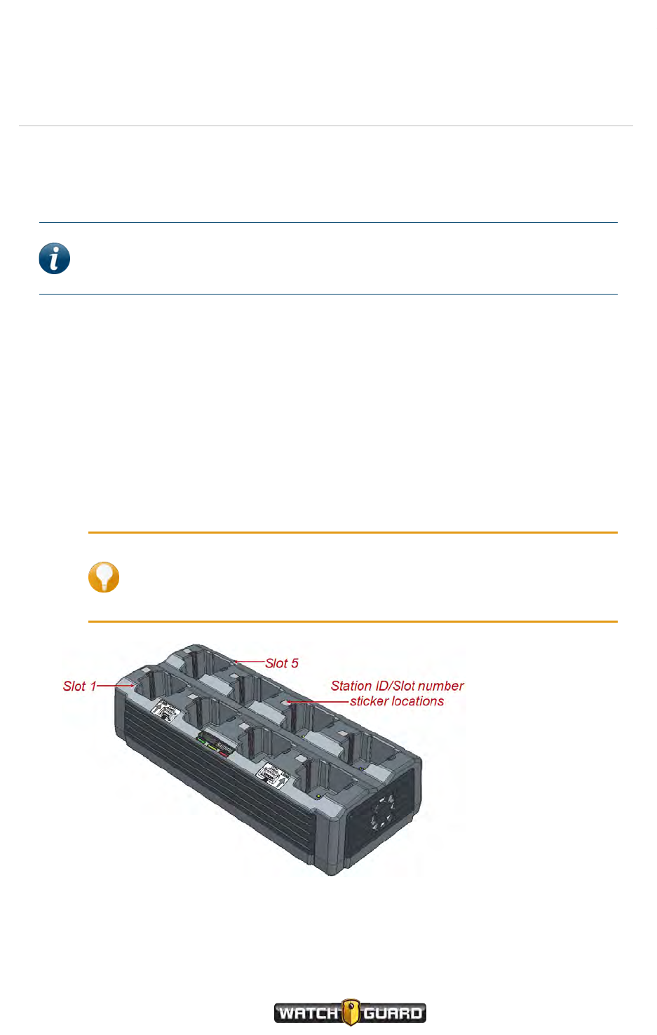
VISTA Transfer Station Hardware
VISTA Transfer Station Hardware
When you set up the VISTA Transfer Station hardware, you connect the power cable and the
Ethernet cable to the Transfer Station. You can add labels to the Transfer Station slots as well, if
desired.
Note: WatchGuard offers rack options for mounting multiple Transfer Stations in
the same location. For more information, contact your WatchGuard
representative.
Included with the VISTA Transfer Station:
lPower cable
lEthernet cable
lSheet of Station ID/Slot # labels
Setting up the hardware
To set up the VISTA Transfer Station hardware:
1. If desired, use the provided Station ID/Slot # stickers to label the Transfer Station slots.
Tip: The provided labels assume an alphabetic Station ID, for example,
B, then slot numbers 1 through 8; so, in this example, for the Transfer
Station with the Station ID of B, you use the labels B1,B2,B3,B4,
B5,B6,B7, and B8.
VISTA Body Camera
WGD00120 Revision
ReviewDraft_111518
119
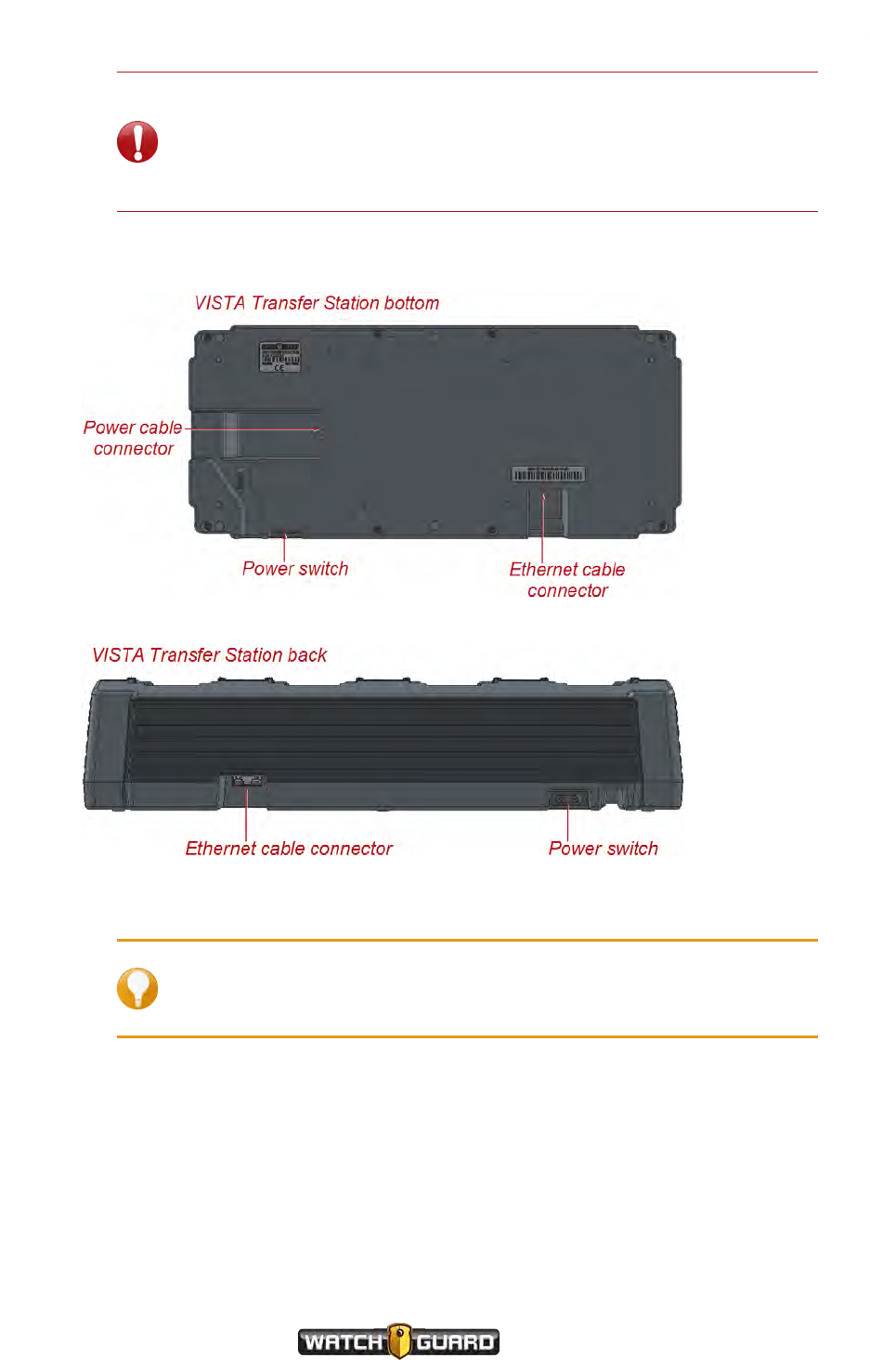
Appendix D: VISTA Transfer Station Setup
Important! You must enter the Station ID that you selected when
you configure the Transfer Station for use with Evidence Library software
(see page 125). The Station ID combined with the Location (also
entered during Transfer Station configuration) indicate a specific Transfer
Station to Evidence Library.
2. Connect the power cable to the power connector on the bottom of the Transfer Station, plug
the power cable into an electrical outlet, then power the Transfer Station ON.
3. Connect the Ethernet cable to the Ethernet connector on the back of the Transfer Station.
4. Connect the other end of the Ethernet cable to a computer that you have set up to access the
Transfer Station's factory default configuration web page.
Tip: You access the default configuration web page using the Transfer
Station factory default IP address: 192.168.2.20. The computer you use
must have access to this network.
To continue setting up the VISTA Transfer Station, follow the instructions on page 125 to
configure the Transfer Station to work with your Evidence Library software.
120
VISTA Body Camera
WGD00120 Revision
ReviewDraft_111518
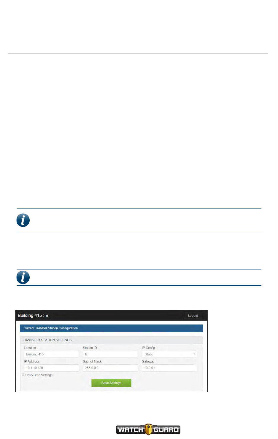
VISTATransfer Station Configuration
VISTATransfer Station Configuration
You configure each VISTA Transfer Station individually using a web page specific to that
Transfer Station. When you configure the VISTA Transfer Station, you configure:
lTransfer Station Settings (below)
lVISTA Settings (page 122)
The configuration web page also allows you to perform some non-configuration administrative
functions for the Transfer Station (page 123).
You access the VISTA Transfer Station's configuration web page using your web browser.
For step-by-step instructions how to configure a VISTA Transfer Station, see Configuring the
Transfer Station on page 125.
Transfer Station Settings
When you configure the Transfer Station Settings, you assign the Transfer Station a
Location name and Station ID. You either assign it a Static IP Address or let your DHCP
server assign its IP address. You can set a date and time for the Transfer Station as well, if
desired.
Note: WatchGuard recommends that you set up a pool of static IP addresses
that you assign to your VISTA Transfer Stations.
The Location and Station ID (along with the Slot # from the VISTA Settings section) are
used by the Evidence Library software to indicate to an officer which VISTA Body Camera he is
checking out.
Note: The Location and Station ID fields each have a 32-character limit.
Static IP
VISTA Body Camera
WGD00120 Revision
ReviewDraft_111518
121
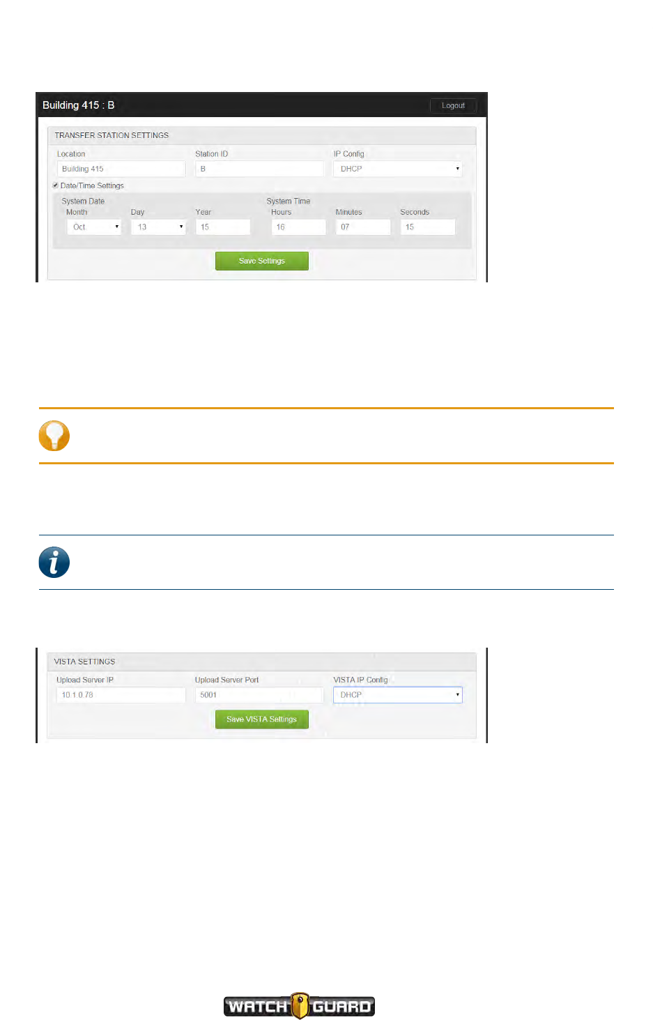
Appendix D: VISTA Transfer Station Setup
DHCP and Date/Time Settings
VISTASettings
When you configure the VISTA Settings, you set the Upload Server IP address and Port,
indicating the Evidence Library server where your VISTA Body Cameras should upload video
evidence.
Tip: The upload server for Evidence Library can also be called the Wireless
Import Service.
You either let your DHCP server assign IP addresses to the VISTA Body Camera slots or you
assign a Static IP Address to each slot individually.
Note: WatchGuard recommends that you let your DHCP server assign the slot IP
addresses.
DHCP
122
VISTA Body Camera
WGD00120 Revision
ReviewDraft_111518
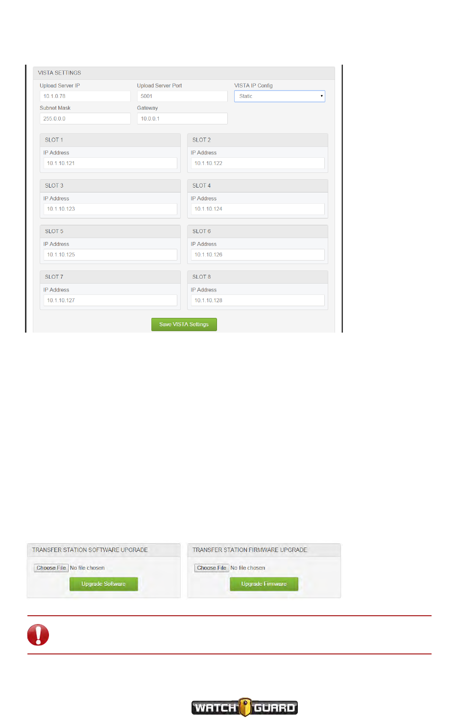
Static IP
Static IP
Transfer Station administrative functions
You can perform a number of administrative tasks for the Transfer Station from the
configuration page, including:
lUpgrading the Transfer Station software or firmware (below)
lChanging the login credentials for the Transfer Station configuration page (page 124)
lDisabling the configuration page (page 124)
lRestarting the Transfer Station (page 125)
Upgrading the Transfer Station software or firmware
nClick the Choose File button for the upgrade you want to perform, navigate to and select the
appropriate software (.hex file) or firmware (.bit file) upgrade file, then click the appropriate
Upgrade button.
Important! After you have upgraded the Transfer Station, you must power the
Transfer Station off and then on again for the cameras to recognize the upgrade.
VISTA Body Camera
WGD00120 Revision
ReviewDraft_111518
123
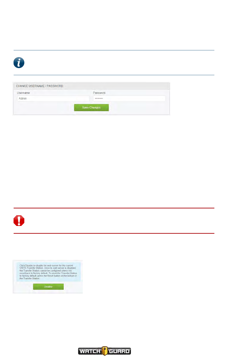
Appendix D: VISTA Transfer Station Setup
Changing the login credentials for the Transfer Station configuration page
The first time you log in to the Transfer Station configuration page, use the default user name,
Admin, and password, V1$T@xfr.
Note: WatchGuard recommends that you change the user name and password
from the default values the first time you log in to the Transfer Station
configuration page.
To change the Username and Password:
nEnter the new credentials in the fields, then click Save Changes.
The system logs you out of the Transfer Station configuration page and asks you to log back in
using the new credentials.
Disabling the configuration page
The Disable feature can function as another level of security. Disabling the configuration page
(web server) after you have finished configuring the Transfer Station prevents others from
accessing the configuration page to make unauthorized changes.
When you disable the configuration page, however, you also prevent authorized administrators
from making changes as needed.
Warning! Disabling the configuration page prevents anyone, including
authorized administrators, from making changes to the VISTA Transfer Station
configuration.
To disable the current VISTA Transfer Station's configuration page (web server):
nClick Disable.
Once you disable the configuration page for the current Transfer Station, you cannot change
any configuration settings or configure the current Transfer Station at all UNLESS you reset the
Transfer Station to factory default. If you reset a Transfer Station back to factory default, all
current settings are lost and you must start the configuration process again from the
beginning.
124
VISTA Body Camera
WGD00120 Revision
ReviewDraft_111518
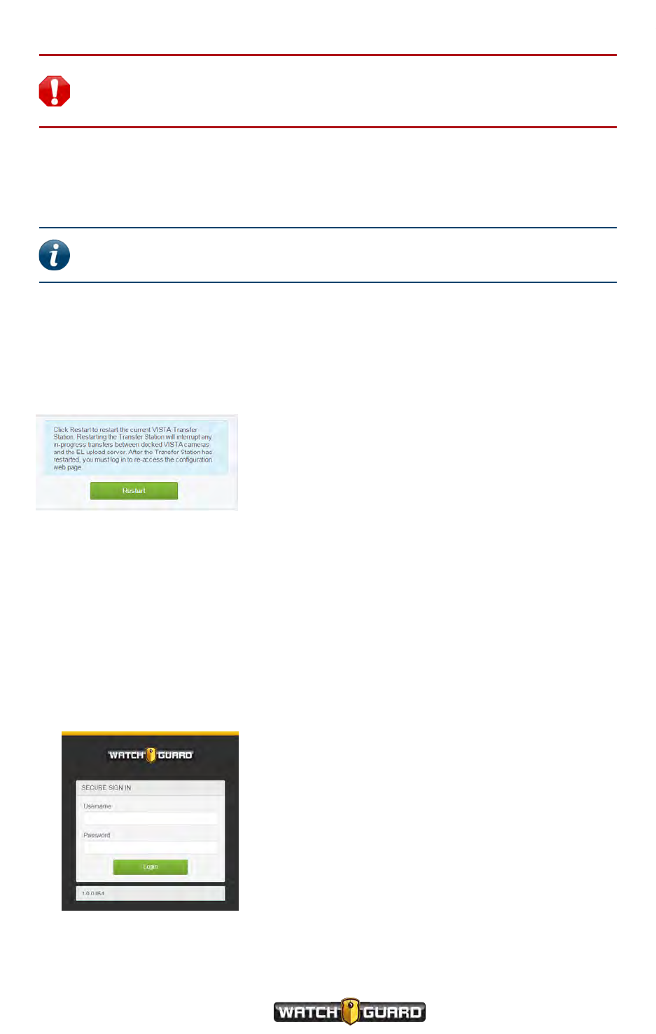
Restarting the Transfer Station
Warning! Resetting a VISTA Transfer Station to factory default reverts any
values you set on the Transfer Station's configuration page back to the default
values.
To reset the VISTA Transfer Station back to factory default:
nUsing a pin or a paper clip, press and hold (for at least 7 seconds) the Reset button on the
bottom of the Transfer Station.
Note: The Reset button is located near the power cable connector on the
bottom of the Transfer Station.
Restarting the Transfer Station
The Restart feature functions as a soft restart of the Transfer Station. To perform a soft restart
of the VISTA Transfer Station:
nClick Restart.
Configuring the Transfer Station
To configure a VISTA Transfer Station:
1. Set up a computer to access a VISTA Transfer Station's factory default configuration web page
at its default IP address, 192.168.2.20.
2. If not already done, connect the Ethernet cable from the Transfer Station to the computer.
3. Open your web browser, enter the Transfer Station default IP address in the browser address
field, and press Enter.
The Secure Sign In screen opens for the connected Transfer Station.
VISTA Body Camera
WGD00120 Revision
ReviewDraft_111518
125
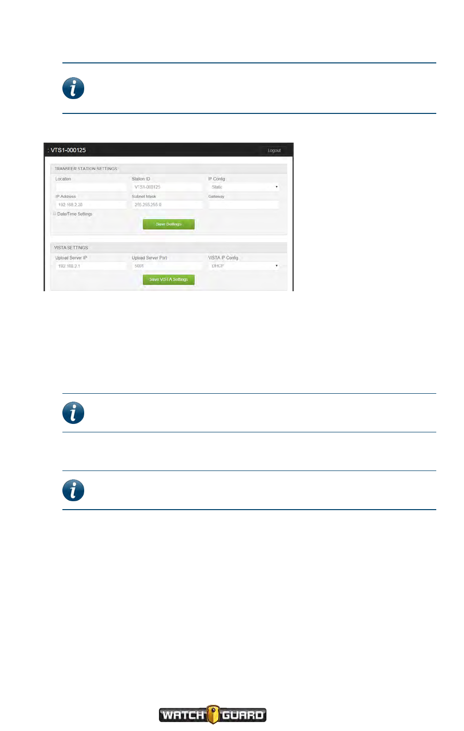
Appendix D: VISTA Transfer Station Setup
4. Enter the default Username and Password (Admin,V1$T@xfr), then click Login.
Note: WatchGuard recommends that you change the default
Username and Password the first time you log in. For more
information, see Transfer Station administrative functions on page 123.
The Transfer Station Configuration page opens showing the default settings.
5. In the Transfer Station Settings section, enter the Location (32-character limit) where
the current Transfer Station will be used, for example, Building 415.
For more information about the Transfer Station Settings section, see Transfer Station
Settings on page 121.
6. Enter the Station ID (32-character limit) that identifies the current Transfer Station, for
example, B.
Note: WatchGuard provides labels that assume an alphabetic Station
ID, for example, B, combined with slot numbers 1 through 8.
7. Select the IP Config type you want to assign to the Transfer Station, either Static or DHCP.
Note: WatchGuard recommends the Static IP Config type for the
Transfer Station.
8. If you selected the Static IP Config type, enter the static IP Address, the Subnet Mask,
and the Gateway that you want to assign to the current Transfer Station.
If you selected the DHCP IP Config type, go to the next step.
9. If desired, click Date/Time Settings and set the date and time local to the Transfer Station.
10. Click Save Settings.
The system logs you out. The default configuration web page is no longer valid for the
connected Transfer Station because the Transfer Station IP address has changed.
11. Enter the new IP address for the connected Transfer Station in your browser address field, then
press Enter.
126
VISTA Body Camera
WGD00120 Revision
ReviewDraft_111518
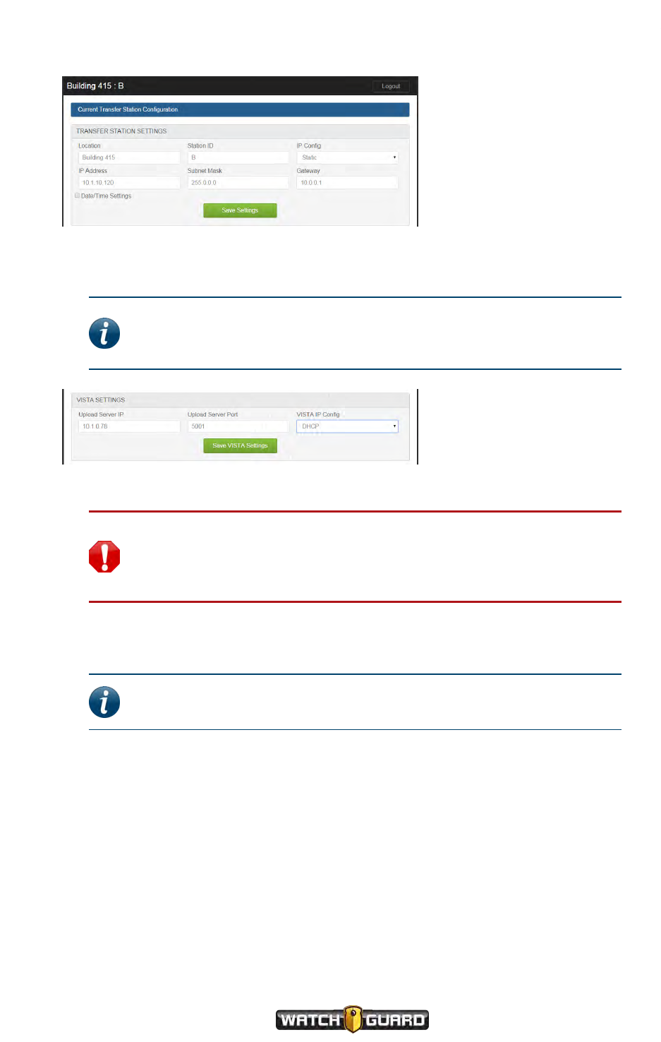
Configuring the Transfer Station
The configuration page opens showing the information you just entered.
12. In the VISTA Settings section, enter the Upload Server IP address.
For more information about the VISTA Settings section, see VISTASettings on page 122.
Note: The upload server is the Evidence Library location where the
VISTA Body Cameras will upload their video evidence. The upload server
for Evidence Library can also be called the Wireless Import Service.
13. Verify that the Upload Server Port is set to 5001.
Warning! Changing the Upload Server Port to something other than
5001 can cause the VISTA Transfer Station to stop working. If you have
questions about the assigned port, contact WatchGuard Technical
Services.
14. Select the VISTA IP Config type you want to assign to the camera slots, either Static or
DHCP.
Note: WatchGuard recommends that you let your DHCP server assign
the slot IP addresses.
15. If you selected the DHCP VISTA IP Config type, go to the next step.
If you selected the Static VISTA IP Config type, enter the camera slot Subnet Mask and
Gateway, then an individual static IP Address for each of the eight slots.
16. Click Save VISTA Settings.
When the Transfer Station has made a successful connection with the upload server, the
amber (center) LED lights up.
Repeat this procedure to set up each VISTA Transfer Station you want to use in your
WatchGuard system.
VISTA Body Camera
WGD00120 Revision
ReviewDraft_111518
127

128
VISTA Body Camera
WGD00120 Revision
ReviewDraft_111518
Appendix D: VISTA Transfer Station Setup
This page intentionally left blank.

Index
Index
4
4RE DVR, recording groups, 82
A
aborting status sequence, 50, 54
access point, 50, 54, 84-85, 90
alerts, 57
battery low
VISTA, 60
XLT, 60
Mobile Charger, 111
periodic, 77
storage full, 58
amber LED
Transfer Station, 65
WiFi Base, 67
assigning a configuration, 35
associating with recording groups, 44, 81
audio
always on, 73
muting, 28, 50, 54
pre-event, 71
Record After the Fact, 73
auto off, 75, 82, 84
automatic
event categorization, 29
event start and stop, 26, 46
B
base connectors
Transfer Station, 65
USB Base, 64
WiFi Base, 68
bases
Mobile Charger, 109
Transfer Station, 65
setting up, 66, 118
USB, 64
setting up, 64
WiFi, 66
setting up, 68
battery, 59
alert
VISTA, 60
XLT, 60
charging, 42, 64-66
extended capacity, 59
saving, 70, 74-76
standard capacity, 59
status
VISTA, 51
XLT, 54
XLT capacity, 60
Battery Charge icon
VISTA, 59
XLT, 60
battery low alert
VISTA, 60
XLT, 60
belt clip
VISTA, 15
XLT, 20
body-mounted camera sensor, 52
wearing, 22-23
buttons
display light, 28-29
VISTA, 50
XLT, 54
power, 24
VISTA, 49
XLT, 53
record, 26
VISTA, 50
XLT, 53
C
cables
Mobile Charger, 109
Transfer Station, 119
USB Base, 64
WiFi Base, 68
camera components
battery, 59
buttons
VISTA, 49
XLT, 53
display
VISTA, 50
XLT, 54
GPS, 62
VISTA Body Camera
WGD00120 Revision
ReviewDraft_111518
129

Index
indicators, 57
lens
VISTA, 49
XLT, 52
microphone
VISTA, 49
XLT, 53
mounting latch, 63
sensor
VISTA, 49
XLT, 52
storage, 57
Wi-Fi, 61
camera sensor, XLT, 52
clip mount, 23
glasses mount, 21
magnetic mount, 22
canceling
maximum recording time warning, 50,
54, 76
sleep warning, 50, 54, 74
capacity
battery
VISTA, 59
XLT, 60
storage, 57-58
capturing evidence, 46
categorizing events, 27, 29
automatic, 29
group recording, 83
selecting categories, 29, 50, 54
SmartConnect, 29, 99
using 4RE, 83
VISTA, 51
XLT, 55
charge time, 42
VISTA, 59
XLT, 60
charging battery, 42
mobile, 108
chest mount, locking, 16
clearing storage, 39
clips, mounting
VISTA, 15
XLT camera sensor, 23
XLT DVR, 20
configuring
camera, 35
tones and vibrations, 57
Transfer Station, 121, 125
confirmations
powering off, 24
record stop, 27
connecting to SmartConnect
first time, 94
continuous video capture, 46, 72
Covert Mode, 77, 102
customizing the camera, 30, 35
D
date/time, 62
VISTA, 51
XLT, 54
DHCP-assigned, Transfer Station, 121-122
display
VISTA, 50
XLT, 54
Display Backlight button, 28-29
VISTA, 50
XLT, 54
Distributed Multi-Peer Recording, 80
DMD Display, 54
docking
associating with recording groups, 44
charging, 42
provisioning, 35
Transfer Station, 33, 65
upgrading firmware, 40
uploading events, 37
USB Base, 31, 64
WiFi Base, 34, 66
E
emptying storage, 39
Ethernet, cable connector, 65, 119
event categorizing, 27, 29
automatic, 29
group recording, 83
selecting categories, 29, 50, 54
SmartConnect, 29
using 4RE, 83
VISTA, 51
XLT, 55
evidence capture, 46
exiting sleep, 74
extended capacity battery, 59
130
VISTA Body Camera
WGD00120 Revision
ReviewDraft_111518

Index
F
firmware, upgrading, 40
camera, 40
Transfer Station, 123
forcing microphone on, 73
forcing power off, 25
fuse, Mobile Charger, 109
G
glasses mount, 21
GPS, 62
status
VISTA, 63
XLT, 55, 63
green LED
camera, 57
Transfer Station, 65
WiFi Base, 67
group recordings, 44, 85
moving out of range, 84, 86
VISTA WiFi behavior, 86
VISTA XLT behavior, 86
H
head-mounted camera sensor, 52
wearing, 21
holster, XLT DVR, 20
hotspot, 50, 54, 84-85, 90-91
status, XLT, 55
hub, USB, 31, 42, 59, 61, 64
I
importing events, 37
indicators
camera, 57
Transfer Station, 65
WiFi Base, 67
L
laptop, 85
latch, mounting, 63
LCD Display, 50
LEDs
camera, 57
Transfer Station, 65
WiFi Base, 67
lens
VISTA, 49
XLT, 52
live stream, 101
live streaming, SmartConnect, 101
location information, 62
locking chest mount, 16
LOW BASE message, 60
LOW BATT message, 60
M
magnetic mount
VISTA, 16
XLT camera sensor, 22
magnets, Mobile Charger, 108
manual event request, 72
maximum recording time, 76
canceling warning, 50, 54, 76
warning, 76
MDC, 85
microphone
forcing on, 73
muting, 28
VISTA, 49
XLT, 53
Mobile Charger, 108
alerts and notifications, 111
base, 109
cable, 109
mounting latch, 63
mounts
belt clip
VISTA, 15
XLT, 20
clip, XLT, 23
holster, XLT DVR, 20
locking chest mount, 16
magnetic, XLT, 22
shirt clip, 15
VISTA, 15
other, 18
XLT, 19
body-mounted camera, 22
DVR, 20
head-mounted camera, 21
muting audio, 28, 50, 54
N
notifications, 57
battery low
VISTA, 60
XLT, 60
Mobile Charger, 111
periodic, 77
storage full, 58
VISTA Body Camera
WGD00120 Revision
ReviewDraft_111518
131

Index
O
Oakley mount, 21
orange LED
Transfer Station, 65
WiFi Base, 67
out of range, recording groups, 86
P
pairing, WiFi Base, 44, 83-84
password, SmartConnect, 94
periodic recording alerts, 77
power
cable connector
Transfer Station, 65
USB Base, 64
WiFi Base, 68
saving, 70, 74-76
Power button, 24
VISTA, 49
XLT, 53
power/data connector, 68
powering off, 24
automatically, 75
confirmation, 24
forcing, 25
powering on, 24
pre-event, 71
protected video, 46
provisioning, 35
Q
Quick Connect, 108
R
radio, 85
RATF, 39, 47, 72
status, XLT, 55
Record After the Fact, 39, 47, 72
Record Start/Stop button, 26
VISTA, 50
XLT, 53
record stop confirmation, 27
record time, 57
recorded events
alerts, 77
definition, 46
group recordings, 85
starting automatically, 26, 80, 82, 84
starting manually, 26
stopping automatically, 26, 76, 84
stopping manually, 27
uploading, 47
recording
alerts, 77
audio, 73
length
VISTA, 51
XLT, 54
status
VISTA, 51
XLT, 55
recording groups, 81
associating, 44
members, 81
4RE DVR, 82
Smart Power Switch, 82
VISTA WiFi, 84
VISTA XLT, 84
WiFi Base, 83
moving out of range, 86
red LED
camera, 57
Transfer Station, 65
WiFi Base, 67
review, 98
rotatable clip, 15
S
saved storage total
VISTA, 51
XLT, 55
sensor
VISTA, 49
XLT, 52
settings, SmartConnect iPhone, 104
signal strength
VISTA, 51, 62-63
XLT, 55, 62-63
Sleep power state, 74
sleep warning, canceling, 50, 54, 74
slot stickers, 119
Smart Power Switch, 82
upgrading, 115
SmartConnect, 84-85, 90, 94
categorizing events, 29, 99
live streaming, 101
settings, 104
starting and stopping events, 26, 102
snapshots, SmartConnect, 98
132
VISTA Body Camera
WGD00120 Revision
ReviewDraft_111518

Index
software, Transfer Station, 121
special features, 70
battery and storage saving, 70
Covert Mode, 71
recording, 70
SSID, SmartConnect, 94
staging firmware, 40
standard capacity battery, 59
start or stop a recorded event, 102
starting recorded events, 26
automatic, 26, 46, 82, 84
manual, 26, 84
recording groups, 80
SmartConnect, 26, 102
static IP, Transfer Station, 121-122
status
aborting sequence, 50, 54
battery
VISTA, 51
XLT, 54
GPS, XLT, 55
hotspot, XLT, 55
RATF, XLT, 55
recording
VISTA, 51
XLT, 55
showing, 50, 54
storage
VISTA, 51
XLT, 55
upload
VISTA, 51
XLT, 55
Wi-Fi signal strength
VISTA, 51
XLT, 55
stickers, Transfer Station, 119
stopping recorded events
4RE DVR, 82
automatic, 26, 46, 76, 84
manual, 27
SmartConnect, 26, 102
storage, 57
clearing, 39, 72
filled, 72
Record After the Fact, 72
saving, 70, 76-77
VISTA, 51
XLT, 55
status
VISTA, 51
XLT, 55
storage-full alert, 58
Storage Percentage number, VISTA, 58
Storage Used icon, XLT, 58
Storage Used meter, VISTA, 58
Storage Used percentage, XLT, 58
subtitles, 47
synchronizing playback, 62, 85
T
tagging event, 29
text overlay, 47
time/date
VISTA, 51
XLT, 54
timestamps, 62
tones and vibrations, 57
Transfer Station, 65
cable connectors, 65
configuring, 125
docking VISTA, 33
LEDs, 65
setting up, 66, 118
hardware, 119
software, 121
slot stickers, 119
upgrading, 123
upgrading camera firmware from, 40
uploading from, 37
Transfer Station Settings, 121
turning on hotspot, 50, 54
U
undocking
Transfer Station, 33
USB Base, 32
WiFi Base, 34
upgrading
camera, 40
Smart Power Switch, 115
Transfer Station, 123
WiFi Base, 115
upload status
VISTA, 51
XLT, 55
uploading recorded events, 37, 47
recording group, 85
VISTA Body Camera
WGD00120 Revision
ReviewDraft_111518
133

Index
Transfer Station, 37
USB Base, 37
WiFi Base, 37
USB
cable connector, 64
hub, 31, 42, 59, 61, 64
USB Base, 64
docking VISTA, 31
setting up, 64
undocking VISTA, 32
upgrading camera firmware, 40
uploading from, 37
V
vibrations and tones, 57
video
continuous capture, 72
pre-event, 71
protected, 46
VISTA Settings, Transfer Station, 122
W
warnings
canceling, 50, 54
maximum recording time, 76
sleep, 74
wearing
VISTA, 15
locking chest mount, 16
MOLLE vest mount, 17
other mounts, 18
XLT, 19
belt clip, 20
body-mounted camera, 22
DVR, 20
head-mounted camera, 21
holster, 20
Wi-Fi
access point, 50, 54, 84-85, 90
antenna connector, 68
feature, 61
signal strength
VISTA, 51, 62
XLT, 55, 62
WiFi Base, 66
charging from, 66
docking VISTA, 34
LEDs, 67
pairing, 44, 83
recording group member, 83
setting up, 68
upgrading, 115
upgradng camera firmware, 40
uploading, 37
wireless
access point, 84-85, 90
radio, 85
workflow, 14
134
VISTA Body Camera
WGD00120 Revision
ReviewDraft_111518