Enlighted CS-D2 Intelligent Light Sensor for Smart Networked Energy Saving Lighting Systems. User Manual PowerPoint Presentation
Enlighted, Inc. Intelligent Light Sensor for Smart Networked Energy Saving Lighting Systems. PowerPoint Presentation
Contents
- 1. Users Manual 1 v2
- 2. Users Manual 2 v2
Users Manual 1 v2

Page 5 Page 6 93-01182-02 Rev04 082115 Page 1
Copyright © 2015 Enlighted Inc. All rights reserved.
All other brand or product names are trademarks of
their respective companies or organizations.
TechnicalSupport
For questions regardingtheinstallation or operation of
this product,contact Enlighted
TechnicalSupport: support@enlightedinc.com
Company Contact Information
Location: 930 Benecia Ave, Sunnyvale, CA 94085
Phone: +1.650.964.1094
Web: enlightedinc.com
FCC and Industry Canada Compliance Information
This equipment has been tested and found to comply with the limits
for a Class A digital device, pursuant to part 15 of the FCC Rules.
These limits are designed to provide reasonable protection against
harmful interference when the equipment is operated in a
commercial environment. This equipment generates, uses, and can
radiate radio frequency energy and, if not installed and used in
accordance with the instruction manual, may cause harmful
interference to radio communications. Operation of this equipment
in a residential area is likely to cause harmful interference in which
case the user will be required to correct the interference at his own
expense.
This device complieswith Part 15 of the FCC Rules and Industry
Canadalicense-exempt RSS standard(s). Operation is subjectto the
following two conditions:
•this devicemay not cause harmful interference, AND
•this device must accept anyinterference received, including
interference that may cause undesiredoperation.
Changes or modifications not expressly approved by Enlighted Inc.
could void the user'sauthority to operate the equipment.
Le présent appareil est conforme aux CNR d'Industrie Canada
applicables aux appareils radio exempts de licence.L'exploitation
est autoriséeauxdeux conditions suivantes:
•l'appareil ne doit pas produire de brouillage,ET
•l'utilisateur de l'appareildoitaccepter tout brouillage
radioélectriquesubi, même si le brouillage est susceptible d'en
compromettre le fonctionnement.
CE
This device complies with the essential requirements and other
relevant requirements of the R&TTE Directive (1999/5/EC). The
equipment is Class 1 radio equipment which can be placed on the
market and be put into service without restrictions in accordance
with article 1(3) of Commission Decision 2000/299/EC (Version July
2014).
Compact Sensor (CS-D2)
Installation Instructions
Model: CS-D2
FCC ID: AQQ-CS-D2
IC: 10138A-CSD2
Figure 1: Compact Sensor (CS-D2)
Shipped Components
•Enlighted Compact Sensor Unit
Items you may Need
•Lock Nut for fixture mounting or
•Spring Arms for Tile mounting
•18 AWG solid copper wire, rated >=300v
Tools you may Need
•1” Drill bit
•Hand drill
•Wire stripper
Page 2 Page 3 Page 4
Step Description
1. Switch off the circuit breaker supplying power to the light.
2The sensor is designed to mount in a 1-inch hole in the
ceiling tile. This sensor is for use with the Philips XSR driver.
3. Make a small circular cut (one-inch) in the ceiling tile.
Thread the spring arms around the sensor.
4. Measure the distance between the sensor’s installation
location and the LED driver’s “SR connections,”. Cut two
lengths of 18 AWG solid wire that are at least this length
plus one inch. Strip each end of the two wires leaving 3/8
inch of exposed wire.
5. Insert one end of the pair of wires into the LED driver’s “SR
connections” wire holes, (see Figure 5), and pull the other
end through the hole in the tile. See Figure 2.
6. Insert the free end of the pair of wires into the sensor’s wire
hole. See Figure 2.
7. Push the spring arms together and insert the sensor through
the hole in the tile. See Figure 2.
8. Turn the power on by switching on the circuit breaker.
Tile Mount Sensor Installation
Problem Solution
LED not on Check power and wiring
Solid red LED Sensor fault –replace
Red blinking LED Incompatibility between LED driver and
sensor –replace LED driver and if not
resolved, replace sensor
Troubleshooting
Note: For any reason, if you need to remove the two wires,
push down on the tabs located on the rear of the sensor with a
pointed device, and remove the wires while continuing to hold
the tab down.
To Enlighted
sensor
Figure 2: Tile Mount Sensor Figure 3: Sensor location in a fixture
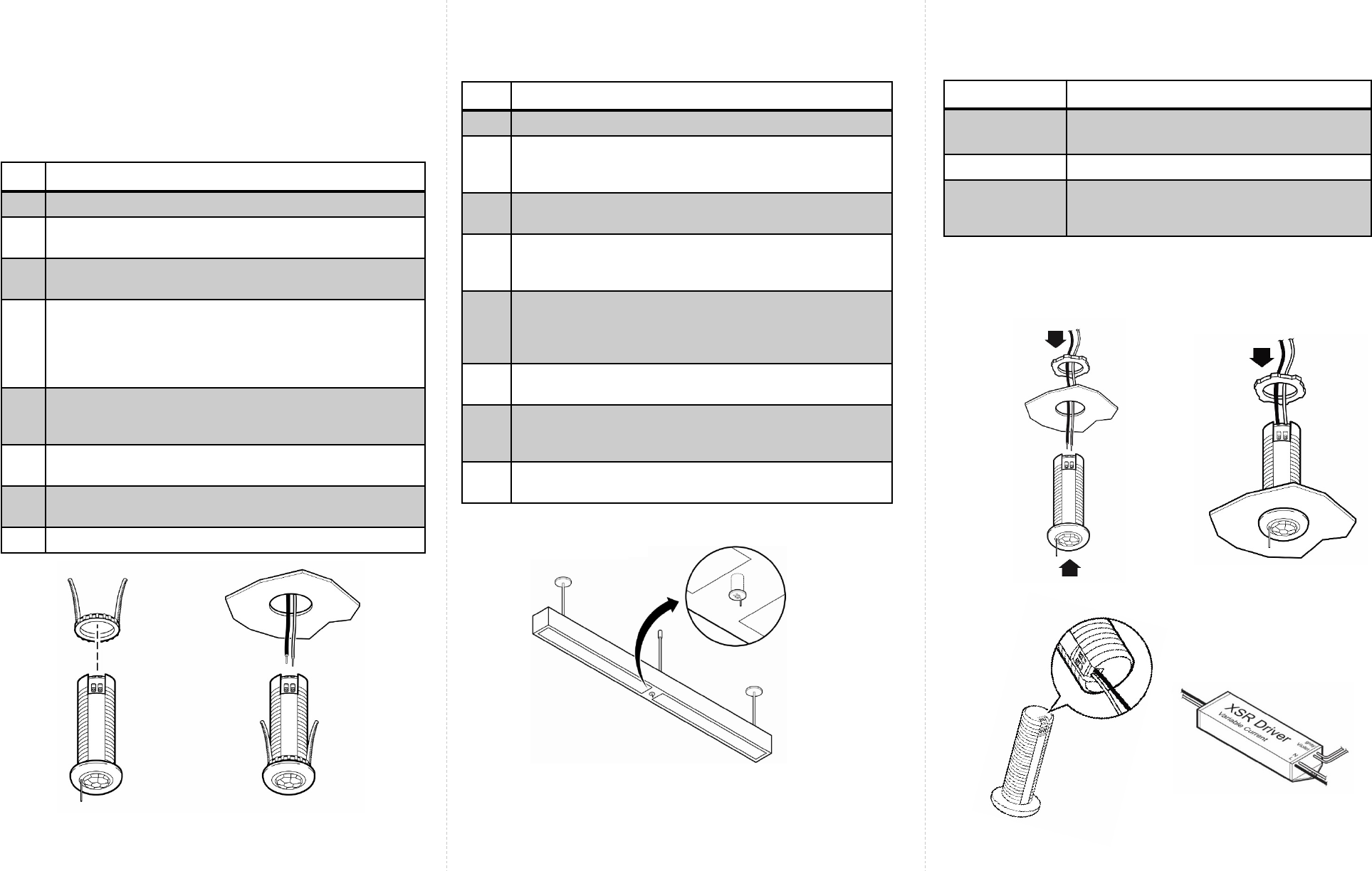
Fixture Mount Sensor Installation
Step Description
1. Switch off the circuit breaker supplying power to the light.
The sensor is designed to mount in a ½ inch trade size
knockout on a fixture. This sensor is for use with the Philips
XSR driver.
2Determine the location for the sensor in the fixture and cut
an existing knockout (½ inch) in the fixture. See Figure 3.
3Insert the compact sensor through the hole in the fixture.
Use the lock nut from behind the sensor to fasten the
compact sensor. See Figure 4.
4. Measure the distance between the sensor’s installation
location and the LED driver’s “SR connections,” and cut
two lengths of 18 AWG solid wire that are at least this
length plus one inch.
5. Strip each end of the two wires leaving 3/8 inch of exposed
wire.
6. Insert one end of the pair of wires in the sensor’s wire holes
and the other end in the LED driver’s “SR connections” wire
holes. See Figure 6.
7. Turn the power on by switching on the circuit
breaker.
Caution
•Installation and maintenance must be performed by a
qualified electrician inaccordance with local, state, and
nationalelectrical codes (NEC) and requirements.
Spring
arms
To
lamps
Push the spring
arms together
and insert the
sensor
Locknut
Figure 5: Wiring Connection
Figure 4: Fixture Mount Sensor