Enterasys Networks Matrix 7H4385 49 Users Manual DFE Platinum Series Hardware Installation Guide
7H4385-49 to the manual ba9116f6-5f2c-4c85-8c05-6c342cb88de6
2015-02-04
: Enterasys-Networks Enterasys-Networks-Matrix-7H4385-49-Users-Manual-366715 enterasys-networks-matrix-7h4385-49-users-manual-366715 enterasys-networks pdf
Open the PDF directly: View PDF ![]() .
.
Page Count: 92
- DFE-Platinum Series Hardware Installation Guide
- Notice
- Contents
- About This Guide
- Introduction
- Network Requirements
- Installation
- Installation Site Requirement
- Unpacking the DFE Module
- Installing Optional Network Expansion Module (NEM)
- Backplane Connections and Installation Rules
- Preparing to Install into a Matrix E7, N1, N3, N5, or N7 Chassis
- Connecting 48 Vdc Power for PoE Operation
- Connecting to the Network
- Connecting to COM Port for Local Management
- Completing the Installation
- Troubleshooting
- Specifications
- Mode Switch Settings and Option Installations
- About PoE (Power over Ethernet)
- Index

Enterasys Matrix™
DFE-Platinum Series
Hardware Installation Guide
7H4385-49
P/N 9033987-05

i
Notice
Enterasys Networksreservestherighttomakechangesinspecificationsandotherinformationcontainedinthis
documentanditswebsitewithoutpriornotice.ThereadershouldinallcasesconsultEnterasys Networksto
determinewhetheranysuchchangeshavebeenmade.
Thehardware,firmware,orsoftwaredescribedinthisdocumentissubjecttochangewithoutnotice.
INNOEVENTSHALLENTERASYS NETWORKSBELIABLEFORANYINCIDENTAL,INDIRECT,SPECIAL,OR
CONSEQUENTIALDAMAGESWHATSOEVER(INCLUDINGBUTNOTLIMITEDTOLOSTPROFITS)ARISING
OUTOFORRELATEDTOTHISDOCUMENT,WEBSITE,ORTHEINFORMATIONCONTAINEDINTHEM,EVEN
IFENTERASYS NETWORKSHASBEENADVISEDOF,KNEWOF,ORSHOULDHAVEKNOWNOF,THE
POSSIBILITYOFSUCHDAMAGES.
Enterasys Networks, Inc.
50MinutemanRoad
Andover,MA01810
©2007Enterasys Networks, Inc.Allrightsreserved.
PartNumber: 9033987‐05 July 2007
ENTERASYS NETWORKS, ENTERASYS MATRIX, LANVIEW, MATRIX, ENTERASYS NETSIGHT, WEBVIEW, and
any logos associated therewith, are trademarks or registered trademarks of Enterasys Networks, Inc., in the United States and
other countries.
Allotherproductnamesmentionedinthismanualmaybetrademarksorregisteredtrademarksoftheirrespective
companies.
DocumentationURL:http://www.enterasys.com/support/manuals
DocumentacionURL:http://www.enterasys.com/support/manuals
DokumentationimInternet:http://www.enterasys.com/support/manuals
Electrical Hazard: Only qualified personnel should perform installation procedures.
Riesgo Electrico: Solamente personal calificado debe realizar procedimientos de instalacion.
Elektrischer Gefahrenhinweis: Installationen sollten nur durch ausgebildetes und qualifiziertes Personal
vorgenommen werden.
ii
REGULATORY COMPLIANCE INFORMATION
Federal Communications Commission (FCC) Notice
ThisdevicecomplieswithPart15oftheFCCrules.Operationissubjecttothefollowingtwoconditions:(1)thisdevice
maynotcauseharmfulinterference,and(2)thisdevicemustacceptanyinterferencereceived,includinginterference
thatmaycauseundesiredoperation.
NOTE: ThisequipmenthasbeentestedandfoundtocomplywiththelimitsforaclassAdigitaldevice,pursuantto
Part15oftheFCCrules.Theselimitsaredesignedtoprovidereasonableprotectionagainstharmfulinterferencewhen
theequipmentisoperatedinacommercialenvironment.Thisequipmentuses,generates,andcanradiateradio
frequencyenergyandifnotinstalledinaccordancewiththeoperator’smanual,maycauseharmfulinterferenceto
radiocommunications.Operationofthisequipmentinaresidentialareaislikelytocauseinterferenceinwhichcase
theuserwillberequiredtocorrecttheinterferenceathisownexpense.
WARNING: Changesormodificationsmadetothisdevicewhicharenotexpresslyapprovedbytheparty
responsibleforcompliancecouldvoidtheuser’sauthoritytooperatetheequipment.
Industry Canada Notice
ThisdigitalapparatusdoesnotexceedtheclassAlimitsforradionoiseemissionsfromdigitalapparatussetoutinthe
RadioInterferenceRegulationsoftheCanadianDepartmentofCommunications.
Leprésentappareilnumériquen’émetpasdebruitsradioélectriquesdépassantleslimitesapplicablesauxappareils
numériquesdelaclassAprescritesdansleRèglementsurlebrouillageradioélectriqueédictéparleministèredes
CommunicationsduCanada.
Class A ITE Notice
WARNING: ThisisaClassAproduct.Inadomesticenvironmentthisproductmaycauseradiointerferenceinwhich
casetheusermayberequiredtotakeadequatemeasures.
Clase A. Aviso de ITE
ADVERTENCIA:EsteesunproductodeClaseA.Enunambientedomésticoesteproductopuedecausarinterferencia
deradioencuyocasopuedeserrequeridotomarmedidasadecuadas.
Klasse A ITE Anmerkung
WARNHINWEIS: DiesesProduktzähltzurKlasseA(Industriebereich).InWohnbereichenkanneshierdurchzu
Funkstörungenkommen,dahersolltenangemesseneVorkehrungenzumSchutzgetroffenwerden.
Product Safety
Thisproductcomplieswiththefollowing:UL60950,CSAC22.2No.60950,73/23/EEC,EN60950,IEC60950,EN 60825,
21 CFR1040.10.
Seguridad del Producto
ElproductodeEnterasyscumpleconlosiguiente:UL60950,CSAC22.2No.60950,73/23/EEC,EN 60950,IEC 60950,
EN 60825,21 CFR1040.10.
Produktsicherheit
DiesesProduktentsprichtdenfolgendenRichtlinien:UL60950,CSAC22.2No.60950,73/23/EEC,EN60950,
IEC 60950,EN60825,21CFR1040.10.
iii
Electromagnetic Compatibility (EMC)
Thisproductcomplieswiththefollowing:47CFRParts2and15,CSAC108.8,89/336/EEC,EN55022,EN61000‐3‐2,
EN 61000‐3‐3,EN55024,AS/NZSCISPR22,VCCIV‐3.
Compatibilidad Electromágnetica (EMC)
EsteproductodeEnterasyscumpleconlosiguiente:47CFRPartes2y15,CSAC108.8,89/336/EEC,EN55022,
EN 55024,EN61000‐3‐2,EN61000‐3‐3,AS/NZSCISPR22,VCCIV‐3.
Elektro- magnetische Kompatibilität ( EMC )
DiesesProduktentsprichtdenfolgendenRichtlinien:47CFRParts2and15,CSAC108.8,89/336/EEC,EN55022,
EN 61000‐3‐2,EN61000‐3‐3,EN55024,AS/NZSCISPR22,VCCIV‐3.
HAZARDOUS SUBSTANCES
ThisproductcomplieswiththerequirementsofEuropeanDirective,2002/95/EC,RestrictionofHazardousSubstances
(RoHS)inElectricalandElectronicEquipment.
EUROPEAN WASTE ELECTRICAL AND ELECTRONIC EQUIPMENT (WEEE) NOTICE
InaccordancewithDirective2002/96/ECoftheEuropeanParliamentonwasteelectricalandelectronicequipment
(WEEE):
1. Thesymbolaboveindicatesthatseparatecollectionofelectricalandelectronicequipmentisrequiredandthatthis
productwasplacedontheEuropeanmarketafterAugust13,2005,thedateofenforcementforDirective
2002/96/EC.
2. Whenthisproducthasreachedtheendofitsserviceablelife,itcannotbedisposedofasunsortedmunicipalwaste.
Itmustbecollectedandtreatedseparately.
3. IthasbeendeterminedbytheEuropeanParliamentthattherearepotentialnegativeeffectsontheenvironment
andhumanhealthasaresultofthepresenceofhazardoussubstancesinelectricalandelectronicequipment.
4. Itistheusers’responsibilitytoutilizetheavailablecollectionsystemtoensureWEEEisproperlytreated.
Forinformationabouttheavailablecollectionsystem,pleasegotohttp://www.enterasys.com/services/support/or
contactEnterasysCustomerSupportat35361705586(Ireland).

iv
ѻ
ѻક䇈ᯢк䰘ӊ
Supplement to Product Instructions
᳝↦᳝ᆇ⠽䋼ܗ㋴(Hazardous Substance)
䚼ӊৡ⿄
(Parts) 䪙
3E
∲
+J
䬝
&G
݁Ӌ䫀
&U
⒈㘨㣃
3%%
⒈Ѡ㣃䝮
3%'(
䞥ሲ䚼ӊ
(Metal Parts) hƻ ƻ h ƻ ƻ
⬉䏃ഫ
(Circuit Modules) hƻ ƻ h ƻ ƻ
⬉㓚ঞ⬉㓚㒘ӊ
(Cables & Cable Assemblies) hƻ ƻ h ƻ ƻ
ล᭭㘮ড়⠽䚼ӊ
(Plastic and Polymeric parts) ƻƻ ƻ ƻ ƻ h
⬉䏃ᓔ݇
(Circuit Breakers) ƻƻ h h ƻ ƻ
ƻ˖ 㸼⼎䆹᳝↦᳝ᆇ⠽䋼䆹䚼ӊ᠔᳝ഛ䋼ᴤ᭭Ёⱘ䞣ഛ SJ/T 11363-2006 ᷛޚ㾘ᅮⱘ䰤䞣㽕∖ҹϟDŽ
Indicates that the concentration of the hazardous substance in all homogeneous materials in the parts is
below the relevant threshold of the SJ/T 11363-2006 standard.
h˖ 㸼⼎䆹᳝↦᳝ᆇ⠽䋼㟇ᇥ䆹䚼ӊⱘᶤϔഛ䋼ᴤ᭭Ёⱘ䞣䍙ߎSJ/T 11363-2006 ᷛޚ㾘ᅮⱘ䰤䞣㽕∖DŽ
Indicates that the concentration of the hazardous substance of at least one of all homogeneous
materials in the parts is above the relevant threshold of the SJ/T 11363-2006 standard.
ᇍ䫔ଂП᮹ⱘ᠔ଂѻકᴀ㸼ᰒ⼎
߃߯կᑨ䫒ⱘ⬉ᄤֵᙃѻકৃ㛑ࣙ䖭ѯ⠽䋼DŽ⊼ᛣ᠔ଂѻકЁৃ㛑Ӯгৃ㛑ϡӮ᳝᠔᳝᠔߫ⱘ䚼ӊDŽ
This table shows where these substances may be found in the supply chain of Enterasys’ electronic
information products, as of the date of sale of the enclosed product. Note that some of the component types
listed above may or may not be a part of the enclosed product.
50
ℸ⦃ֱՓ⫼ᳳ䰤া䗖⫼ѢѻકᰃѻકݠЁ᠔㾘ᅮⱘᴵӊϟᎹ
The Environmentally Friendly Use Period (EFUP) for all enclosed products and their parts
are per the symbol shown here, unless otherwise marked. Certain parts may have a
different EFUP (for example, battery modules) and so are marked to reflect such. The
Environmentally Friendly Use Period is valid only when the product is operated under the
conditions defined in the product manual.
䰸䴲⡍߿ⱘᷛ⊼ℸᷛᖫЎ䩜ᇍ᠔⍝ঞѻકⱘ⦃ֱՓ⫼ᳳᷛᖫᶤѯ䳊䚼ӊӮ
᳝ϔϾϡৠⱘ⦃ֱՓ⫼ᳳ՟བ⬉∴ऩܗഫ䌈݊ѻકϞ
v
VCCI Notice
ThisisaclassAproductbasedonthestandardoftheVoluntaryControlCouncilforInterferencebyInformation
TechnologyEquipment(VCCI).Ifthisequipmentisusedinadomesticenvironment,radiodisturbancemayarise.
Whensuchtroubleoccurs,theusermayberequiredtotakecorrectiveactions.
BSMI EMC Statement — Taiwan
ThisisaclassAproduct.Inadomesticenvironmentthisproductmaycauseradiointerferenceinwhichcasetheuser
mayberequiredtotakeadequatemeasures.
Safety Information
Class 1 Laser Transceivers
The single mode network expansion modules use Class 1 laser transceivers.
Read the following safety information before installing or operating these modules.
TheClass1lasertransceiversuseanopticalfeedbacklooptomaintainClass1operationlimits.Thiscontrolloop
eliminatestheneedformaintenancechecksoradjustments.Theoutputisfactoryset,anddoesnotallowanyuser
adjustment.Class1Lasertransceiverscomplywiththefollowingsafetystandards:
•21CFR1040.10and1040.11U.S.DepartmentofHealthandHumanServices(FDA).
•IECPublication825(InternationalElectrotechnicalCommission).
• CENELECEN60825(EuropeanCommitteeforElectrotechnicalStandardization).
Whenoperatingwithintheirperformancelimitations,lasertransceiveroutputmeetstheClass1accessibleemission
limitofallthreestandards.Class1levelsoflaserradiationarenotconsideredhazardous.
Whentheconnectorisinplace,alllaserradiationremainswithinthefiber.Themaximumamountofradiantpower
exitingthefiber(undernormalconditions)is‐12.6dBmor55x10‐6watts.
Removingtheopticalconnectorfromthetransceiverallowslaserradiationtoemitdirectlyfromtheopticalport.The
maximumradiancefromtheopticalport(underworstcaseconditions)is0.8Wcm‐2or8x103Wm2sr‐1.
Donotuseopticalinstrumentstoviewthelaseroutput.Theuseofopticalinstrumentstoviewlaseroutput
increaseseyehazard.Whenviewingtheoutputopticalport,powermustberemovedfromthenetworkadapter.
vi
Declaration of Conformity
ApplicationofCouncilDirective(s): 89/336/EEC
73/23/EEC
Manufacturer’sName: Enterasys Networks, Inc.
Manufacturer’sAddress: 50MinutemanRoad
Andover,MA01810
USA
EuropeanRepresentativeAddress: Enterasys Networks,Ltd.
NexusHouse,NewburyBusinessPark
LondonRoad,Newbury
BerkshireRG142PZ,England
ConformancetoDirective(s)/ProductStandards: ECDirective89/336/EEC
EN55022
EN61000‐3‐2
EN61000‐3‐3
EN55024
ECDirective73/23/EEC
EN60950
EN60825
EquipmentType/Environment: NetworkingEquipment,foruseinaCommercial
orLightIndustrialEnvironment.
Enterasys Networks, Inc.declaresthattheequipmentpackagedwiththisnoticeconformstotheabovedirectives.
vii
ENTERASYS NETWORKS, INC. FIRMWARE LICENSE AGREEMENT
BEFORE OPENING OR UTILIZING THE ENCLOSED PRODUCT,
CAREFULLY READ THIS LICENSE AGREEMENT.
Thisdocumentisanagreement(“Agreement”)betweentheenduser(“You”)andEnterasysNetworks,Inc.,onbehalf
ofitselfanditsAffiliates(ashereinafterdefined)(“Enterasys”)thatsetsforthYourrightsandobligationswithrespect
totheEnterasyssoftwareprogram/firmware(includinganyaccompanyingdocumentation,hardwareormedia)
(“Program”)inthepackageandprevailsoveranyadditional,conflictingorinconsistenttermsandconditions
appearingonanypurchaseorderorotherdocumentsubmittedbyYou.“Affiliate”meansanyperson,partnership,
corporation,limitedliabilitycompany,otherformofenterprisethatdirectlyorindirectlythroughoneormore
intermediaries,controls,oriscontrolledby,orisundercommoncontrolwiththepartyspecified.ThisAgreement
constitutestheentireunderstandingbetweentheparties,withrespecttothesubjectmatterofthisAgreement.The
Programmaybecontainedinfirmware,chipsorothermedia.
BYINSTALLINGOROTHERWISEUSINGTHEPROGRAM,YOUREPRESENTTHATYOUAREAUTHORIZEDTO
ACCEPTTHESETERMSONBEHALFOFTHEENDUSER(IFTHEENDUSERISANENTITYONWHOSEBEHALF
YOUAREAUTHORIZEDTOACT,“YOU”AND“YOUR”SHALLBEDEEMEDTOREFERTOSUCHENTITY)AND
THATYOUAGREETHATYOUAREBOUNDBYTHETERMSOFTHISAGREEMENT,WHICHINCLUDES,
AMONGOTHERPROVISIONS,THELICENSE,THEDISCLAIMEROFWARRANTYANDTHELIMITATIONOF
LIABILITY.IFYOUDONOTAGREETOTHETERMSOFTHISAGREEMENTORARENOTAUTHORIZEDTO
ENTERINTOTHISAGREEMENT,ENTERASYSISUNWILLINGTOLICENSETHEPROGRAMTOYOUANDYOU
AGREETORETURNTHEUNOPENEDPRODUCTTOENTERASYSORYOURDEALER,IFANY,WITHINTEN
(10)DAYSFOLLOWINGTHEDATEOFRECEIPTFORAFULLREFUND.
IFYOUHAVEANYQUESTIONSABOUTTHISAGREEMENT,CONTACTENTERASYSNETWORKS,LEGAL
DEPARTMENTAT(978)684‐1000.
YouandEnterasysagreeasfollows:
1. LICENSE. Youhavethenon‐exclusiveandnon‐transferablerighttouseonlytheone(1)copyoftheProgram
providedinthispackagesubjecttothetermsandconditionsofthisAgreement.
2. RESTRICTIONS. ExceptasotherwiseauthorizedinwritingbyEnterasys,Youmaynot,normayYoupermitany
thirdpartyto:
(a) Reverseengineer,decompile,disassembleormodifytheProgram,inwholeorinpart,includingforreasons
oferrorcorrectionorinteroperability,excepttotheextentexpresslypermittedbyapplicablelawandtothe
extentthepartiesshallnotbepermittedbythatapplicablelaw,suchrightsareexpresslyexcluded.
InformationnecessarytoachieveinteroperabilityorcorrecterrorsisavailablefromEnterasysuponrequest
anduponpaymentofEnterasys’applicablefee.
(b) IncorporatethePrograminwholeorinpart,inanyotherproductorcreatederivativeworksbasedonthe
Program,inwholeorinpart.
(c) Publish,disclose,copyreproduceortransmittheProgram,inwholeorinpart.
(d) Assign,sell,license,sublicense,rent,lease,encumberbywayofsecurityinterest,pledgeorotherwisetransfer
theProgram,inwholeorinpart.
(e) Removeanycopyright,trademark,proprietaryrights,disclaimerorwarningnoticeincludedonorembedded
inanypartoftheProgram.
viii
3. APPLICABLELAW. ThisAgreementshallbeinterpretedandgovernedunderthelawsandinthestateand
federalcourtsoftheCommonwealthofMassachusettswithoutregardtoitsconflictsoflawsprovisions.Youacceptthe
personaljurisdictionandvenueoftheCommonwealthofMassachusettscourts.Noneofthe1980UnitedNations
ConventionontheLimitationPeriodintheInternationalSaleofGoods,andtheUniformComputerInformation
TransactionsActshallapplytothisAgreement.
4. EXPORTRESTRICTIONS. YouunderstandthatEnterasysanditsAffiliatesaresubjecttoregulationbyagencies
oftheU.S.Government,includingtheU.S.DepartmentofCommerce,whichprohibitexportordiversionofcertain
technicalproductstocertaincountries,unlessalicensetoexporttheproductisobtainedfromtheU.S.Governmentor
anexceptionfromobtainingsuchlicensemayberelieduponbytheexportingparty.
IftheProgramisexportedfromtheUnitedStatespursuanttotheLicenseExceptionCIVundertheU.S.Export
AdministrationRegulations,YouagreethatYouareacivilenduseroftheProgramandagreethatYouwillusethe
Programforcivilendusesonlyandnotformilitarypurposes.
IftheProgramisexportedfromtheUnitedStatespursuanttotheLicenseExceptionTSRundertheU.S.Export
AdministrationRegulations,inadditiontotherestrictionontransfersetforthinSection1or2ofthisAgreement,You
agreenotto(i)reexportorreleasetheProgram,thesourcecodefortheProgramortechnologytoanationalofa
countryinCountryGroupsD:1orE:2(Albania,Armenia,Azerbaijan,Belarus,Cambodia,Cuba,Georgia,Iraq,
Kazakhstan,Laos,Libya,Macau,Moldova,Mongolia,NorthKorea,thePeople’sRepublicofChina,Russia,Tajikistan,
Turkmenistan,Ukraine,Uzbekistan,Vietnam,orsuchothercountriesasmaybedesignatedbytheUnitedStates
Government),(ii)exporttoCountryGroupsD:1orE:2(asdefinedherein)thedirectproductoftheProgramorthe
technology,ifsuchforeignproduceddirectproductissubjecttonationalsecuritycontrolsasidentifiedontheU.S.
CommerceControlList,or(iii)ifthedirectproductofthetechnologyisacompleteplantoranymajorcomponentofa
plant,exporttoCountryGroupsD:1orE:2thedirectproductoftheplantoramajorcomponentthereof,ifsuch
foreignproduceddirectproductissubjecttonationalsecuritycontrolsasidentifiedontheU.S.CommerceControl
ListorissubjecttoStateDepartmentcontrolsundertheU.S.MunitionsList.
5. UNITEDSTATESGOVERNMENTRESTRICTEDRIGHTS. TheenclosedProgram(i)wasdevelopedsolelyat
privateexpense;(ii)contains“restrictedcomputersoftware”submittedwithrestrictedrightsinaccordancewithsection
52.227‐19(a)through(d)oftheCommercialComputerSoftware‐RestrictedRightsClauseanditssuccessors,and(iii)in
allrespectsisproprietarydatabelongingtoEnterasysand/oritssuppliers.ForDepartmentofDefenseunits,the
ProgramisconsideredcommercialcomputersoftwareinaccordancewithDFARSsection227.7202‐3anditssuccessors,
anduse,duplication,ordisclosurebytheU.S.Governmentissubjecttorestrictionssetforthherein.
6. DISCLAIMEROFWARRANTY. EXCEPTFORTHOSEWARRANTIESEXPRESSLYPROVIDEDTOYOUIN
WRITINGBYENTERASYS,ENTERASYSDISCLAIMSALLWARRANTIES,EITHEREXPRESSORIMPLIED,
INCLUDINGBUTNOTLIMITEDTOIMPLIEDWARRANTIESOFMERCHANTABILITY,SATISFACTORY
QUALITY,FITNESSFORAPARTICULARPURPOSE,TITLEANDNON‐INFRINGEMENTWITHRESPECTTOTHE
PROGRAM.IFIMPLIEDWARRANTIESMAYNOTBEDISCLAIMEDBYAPPLICABLELAW,THENANYIMPLIED
WARRANTIESARELIMITEDINDURATIONTOTHIRTY(30)DAYSAFTERDELIVERYOFTHEPROGRAMTO
YOU.
7. LIMITATIONOFLIABILITY. INNOEVENTSHALLENTERASYSORITSSUPPLIERSBELIABLEFORANY
DAMAGESWHATSOEVER(INCLUDING,WITHOUTLIMITATION,DAMAGESFORLOSSOFBUSINESS,
PROFITS,BUSINESSINTERRUPTION,LOSSOFBUSINESSINFORMATION,SPECIAL,INCIDENTAL,
CONSEQUENTIAL,ORRELIANCEDAMAGES,OROTHERLOSS)ARISINGOUTOFTHEUSEORINABILITYTO
USETHEPROGRAM,EVENIFENTERASYSHASBEENADVISEDOFTHEPOSSIBILITYOFSUCHDAMAGES.
THISFOREGOINGLIMITATIONSHALLAPPLYREGARDLESSOFTHECAUSEOFACTIONUNDERWHICH
DAMAGESARESOUGHT.
THECUMULATIVELIABILITYOFENTERASYSTOYOUFORALLCLAIMSRELATINGTOTHEPROGRAM,
INCONTRACT,TORTOROTHERWISE,SHALLNOTEXCEEDTHETOTALAMOUNTOFFEESPAIDTO
ENTERASYSBYYOUFORTHERIGHTSGRANTEDHEREIN.
ix
8. AUDITRIGHTS. YouherebyacknowledgethattheintellectualpropertyrightsassociatedwiththeProgramare
ofcriticalvaluetoEnterasys,and,accordingly,Youherebyagreetomaintaincompletebooks,recordsandaccounts
showing(i)licensefeesdueandpaid,and(ii)theuse,copyinganddeploymentoftheProgram.Youalsograntto
Enterasysanditsauthorizedrepresentatives,uponreasonablenotice,therighttoauditandexamineduringYour
normalbusinesshours,Yourbooks,records,accountsandhardwaredevicesuponwhichtheProgrammaybedeployed
toverifycompliancewiththisAgreement,includingtheverificationofthelicensefeesdueandpaidEnterasysandthe
use,copyinganddeploymentoftheProgram.Enterasys’rightofexaminationshallbeexercisedreasonably,ingood
faithandinamannercalculatedtonotunreasonablyinterferewithYourbusiness.Intheeventsuchauditdiscovers
non‐compliancewiththisAgreement,includingcopiesoftheProgrammade,usedordeployedinbreachofthis
Agreement,YoushallpromptlypaytoEnterasystheappropriatelicensefees.Enterasysreservestheright,tobe
exercisedinitssolediscretionandwithoutpriornotice,toterminatethislicense,effectiveimmediately,forfailureto
complywiththisAgreement.Uponanysuchtermination,YoushallimmediatelyceasealluseoftheProgramandshall
returntoEnterasystheProgramandallcopiesoftheProgram.
9. OWNERSHIP. Thisisalicenseagreementandnotanagreementforsale.Youacknowledgeandagreethatthe
Programconstitutestradesecretsand/orcopyrightedmaterialofEnterasysand/oritssuppliers.Youagreeto
implementreasonablesecuritymeasurestoprotectsuchtradesecretsandcopyrightedmaterial.Allright,titleand
interestinandtotheProgramshallremainwithEnterasysand/oritssuppliers.Allrightsnotspecificallygrantedto
YoushallbereservedtoEnterasys.
10. ENFORCEMENT. YouacknowledgeandagreethatanybreachofSections2,4,or9ofthisAgreementbyYoumay
causeEnterasysirreparabledamageforwhichrecoveryofmoneydamageswouldbeinadequate,andthatEnterasys
maybeentitledtoseektimelyinjunctiverelieftoprotectEnterasys’rightsunderthisAgreementinadditiontoanyand
allremediesavailableatlaw.
11. ASSIGNMENT. Youmaynotassign,transferorsublicensethisAgreementoranyofYourrightsorobligations
underthisAgreement,exceptthatYoumayassignthisAgreementtoanypersonorentitywhichacquiressubstantially
allofYourstockassets.EnterasysmayassignthisAgreementinitssolediscretion.ThisAgreementshallbebinding
uponandinuretothebenefitoftheparties,theirlegalrepresentatives,permittedtransferees,successorsandassignsas
permittedbythisAgreement.Anyattemptedassignment,transferorsublicenseinviolationofthetermsofthis
AgreementshallbevoidandabreachofthisAgreement.
12. WAIVER. AwaiverbyEnterasysofabreachofanyofthetermsandconditionsofthisAgreementmustbein
writingandwillnotbeconstruedasawaiverofanysubsequentbreachofsuchtermorcondition.Enterasys’failureto
enforceatermuponYourbreachofsuchtermshallnotbeconstruedasawaiverofYourbreachorpreventenforcement
onanyotheroccasion.
13. SEVERABILITY. IntheeventanyprovisionofthisAgreementisfoundtobeinvalid,illegalorunenforceable,the
validity,legalityandenforceabilityofanyoftheremainingprovisionsshallnotinanywaybeaffectedorimpaired
thereby,andthatprovisionshallbereformed,construedandenforcedtothemaximumextentpermissible.Anysuch
invalidity,illegality,orunenforceabilityinanyjurisdictionshallnotinvalidateorrenderillegalorunenforceablesuch
provisioninanyotherjurisdiction.
14. TERMINATION. EnterasysmayterminatethisAgreementimmediatelyuponYourbreachofanyoftheterms
andconditionsofthisAgreement.Uponanysuchtermination,YoushallimmediatelyceasealluseoftheProgramand
shallreturntoEnterasystheProgramandallcopiesoftheProgram.
x

xi
Contents
About This Guide
Who Should Use This Guide ............................................................................................................... xv
How to Use This Guide ...................................................................................................................... xvi
Related Documents ........................................................................................................................... xvi
Conventions Used in This Guide .......................................................................................................xvii
Getting Help ......................................................................................................................................xviii
Chapter 1: Introduction
Overview of DFE-Platinum Series Module Capabilities .....................................................................1-2
DFE-Platinum 7H4385-49 PoE Module .............................................................................................1-3
Connectivity .......................................................................................................................................1-5
Management ......................................................................................................................................1-5
Switch Configuration Using WebView .........................................................................................1-5
Switch Configuration Using CLI Commands ...............................................................................1-5
Standards Compatibility .....................................................................................................................1-5
Secure Networks Policy Support .......................................................................................................1-6
LANVIEW Diagnostic LEDs ...............................................................................................................1-6
Chapter 2: Network Requirements
Link Aggregation ................................................................................................................................2-1
Module Placement in a Matrix E7 Chassis ........................................................................................2-2
FTM Bridge Function and Optional Interface Module ........................................................................2-2
10BASE-T Network ............................................................................................................................2-2
100BASE-TX Network .......................................................................................................................2-3
Chapter 3: Installation
Installation Site Requirement .............................................................................................................3-2
Unpacking the DFE Module ...............................................................................................................3-2
Installing Optional Network Expansion Module (NEM) ......................................................................3-3
Backplane Connections and Installation Rules ..................................................................................3-3
FTM1 and FTM2 Connectivity .....................................................................................................3-3
Module Placement and Installation Rules ...................................................................................3-4
Preparing to Install into a Matrix E7, N1, N3, N5, or N7 Chassis .......................................................3-7
Installing the 7H4385-49 into a Matrix E7 or Matrix N7 Chassis .................................................3-8
Installing the 7H4385-49 into Matrix N1, N3, or N5 Chassis .....................................................3-11
Connecting 48 Vdc Power for PoE Operation ..................................................................................3-14
Connecting to the Network ...............................................................................................................3-15
Connecting UTP Cables to 7H4385-49 .....................................................................................3-15
Connecting to COM Port for Local Management .............................................................................3-20
What Is Needed .........................................................................................................................3-20
Connecting to an IBM PC or Compatible Device .......................................................................3-20
Connecting to a VT Series Terminal ..........................................................................................3-21
xii
Connecting to a Modem ............................................................................................................3-22
Adapter Wiring and Signal Assignments ...................................................................................3-24
Completing the Installation ...............................................................................................................3-26
Completing the Installation of a New System ............................................................................3-26
Completing the Installation of a DFE Module in an Existing System .........................................3-28
Chapter 4: Troubleshooting
Using LANVIEW .................................................................................................................................4-1
About the Management (MGMT) LED .........................................................................................4-1
Viewing the Receive and Transmit Activity ..................................................................................4-2
Viewing the PoE Port Status .......................................................................................................4-2
Troubleshooting Checklist ..................................................................................................................4-6
Overview of DFE Module Shutdown Procedure ................................................................................4-8
Recommended Shutdown Procedure Using OFFLINE/RESET Switch .......................................4-9
Last Resort Shutdown Procedure Using OFFLINE/RESET Switch ...........................................4-10
Appendix A: Specifications
DFE Module Specifications ............................................................................................................... A-1
COM Port Pinout Assignments ......................................................................................................... A-2
Regulatory Compliance ..................................................................................................................... A-3
Appendix B: Mode Switch Settings and Option Installations
Required Tools .................................................................................................................................. B-1
Setting the Mode Switches ............................................................................................................... B-2
Memory Locations and Replacement Procedures ............................................................................ B-3
Gaining Access to Memory Modules ................................................................................................ B-4
Removing the Safety Cover ........................................................................................................ B-5
DRAM SIMM Replacement Procedure ....................................................................................... B-7
DIMM Replacement Procedure ................................................................................................ B-10
Installing the Network Expansion Module (NEM) ..................................................................... B-11
Reinstalling the Safety Cover ................................................................................................... B-13
Appendix C: About PoE (Power over Ethernet)
Overview ........................................................................................................................................... C-1
Proprietary PD Detection ............................................................................................................ C-2
Power Interface .......................................................................................................................... C-2
Matrix N5 Backplane 48 Vdc Interface ....................................................................................... C-2
Front Panel 48 Vdc Interface ...................................................................................................... C-2
PoE Port Status LEDs ................................................................................................................ C-3
Index
xiii
Figures
1-1 7H4385-49 DFE-Platinum Module .........................................................................................1-4
3-1 Examples, Module Placement in Matrix E7 Chassis..............................................................3-4
3-2 Installing Module into Matrix E7 or N7 Chassis (Matrix E7 shown)......................................3-10
3-3 Installing Module into Matrix N3, N5, or N1 Chassis (N3 shown) ........................................3-13
3-4 Connecting a Twisted Pair Segment with RJ45 Connector .................................................3-16
3-5 Four-Wire Crossover Cable RJ45 Pinouts, Connections Between Hub Devices.................3-17
3-6 Four-Wire Straight-Through Cable RJ45 Pinouts, Connections
Between Switches and End User Devices ...........................................................................3-18
3-7 Eight-Wire Crossover Cable RJ45 Pinouts, Connections Between Hub Devices................3-18
3-8 Eight-Wire Straight-Through Cable RJ45 Pinouts, Connections
Between Switches and End User Devices ...........................................................................3-19
3-9 Connecting an IBM PC or Compatible .................................................................................3-21
3-10 Connecting a VT Series Terminal ........................................................................................3-22
3-11 Connecting to a Modem .......................................................................................................3-23
3-12 Matrix DFE Startup Screen Example (N7 Chassis) .............................................................3-27
4-1 LANVIEW LEDs .....................................................................................................................4-2
4-2 OFFLINE/RESET Switch .......................................................................................................4-9
B-1 Mode Switch Location (7H4385-49 shown without safety cover).......................................... B-3
B-2 DIMM and DRAM SIMM Locations (7H4385-49 shown without safety cover)...................... B-4
B-3 Removing the Safety Cover .................................................................................................. B-6
B-4 Removing the Optional Network Expansion Module............................................................. B-7
B-5 Removing the Existing DRAM SIMM .................................................................................... B-8
B-6 Installing the DRAM SIMM .................................................................................................... B-9
B-7 Removing the Existing DIMM.............................................................................................. B-10
B-8 Installing the DIMM ............................................................................................................. B-11
B-9 Installing the Network Expansion Module ........................................................................... B-12
B-10 Installing the Safety Cover .................................................................................................. B-14
Tables
3-1 Contents of 7H4385-49 Module Carton .................................................................................3-2
4-1 LANVIEW LEDs .....................................................................................................................4-3
4-2 Troubleshooting Checklist......................................................................................................4-6
A-1 7H4385-49 Specifications .....................................................................................................A-1
A-2 COM Port Pin Assignments .................................................................................................. A-2
A-3 Compliance Standards.......................................................................................................... A-3
C-1 Powered Device Classifications ............................................................................................ C-1
C-2 PoE Status LED Indications.................................................................................................. C-3
xiv
DFE-Platinum Series Hardware Installation Guide xv
About This Guide
Thisguideprovidesanoverview,installationandtroubleshootinginstructions,and
specificationsfortheEnterasysMatrix™7H4385‐49DFE‐PlatinumPoEmodule.
ForinformationabouttheCLI(CommandLineInterface)setofcommandsusedto
configureandmanagethePlatinumDFEmodules,refertotheEnterasysMatrix
DFE‐PlatinumSeriesConfigurationGuide.
Who Should Use This Guide
Thisguideisintendedforanetworkadministratorresponsibleforinstallingandsetting
uptheDFE‐PlatinumPoEmodule.
Note: In this guide, the following terms are used:
•DFE refers to Distributed Forwarding Engine series of modules.
•DFE module or module refers to the 7H4385-49, unless otherwise noted.
•Network expansion module (NEM) refers to an optional uplink card installed on the
main logic board and accessible through the option slot of the 7H4385-49.
•PoE refers to Power over Ethernet.
•PD refers to Powered Device, which is a device that is PoE compliant to operate using
48 Vdc received through the Ethernet data cabling.
Important Notice
Depending on the firmware version used in the DFE module, some features described in this
document may not be supported. Refer to the Release Notes shipped with the DFE module to
determine which features are supported.
Electrical Hazard: Only qualified personnel should perform installation procedures.
Riesgo Electrico: Solamente personal calificado debe realizar procedimientos de
instalacion.
Elektrischer Gefahrenhinweis: Installationen sollten nur durch ausgebildetes und
qualifiziertes Personal vorgenommen werden.

How to Use This Guide
xvi About This Guide
How to Use This Guide
ThisprefaceprovidesanoverviewofthisguideandtheDFE‐PlatinumSeriesmanualset,
abriefsummaryofeachchapter,definestheconventionsusedinthisdocument,and
instructshowtoobtaintechnicalsupportfromEnterasys Networks.Tolocateinformation
aboutvarioussubjectsinthisguide,refertothefollowingtable:
Related Documents
ThemanualslistedbelowcanbeobtainedfromtheWorldWideWebinAdobeAcrobat
PortableDocumentFormat(PDF)atthefollowingsite:
http://www.enterasys.com/support/manuals
•EnterasysMatrixDFE‐PlatinumSeriesConfigurationGuidedescribeshowtousethe
CommandLineInterfacetosetupandmanagetheDFE‐Platinummodules.
•MatrixN‐SeriesN‐POEPowerSystemInstallationGuidedescribeshowtoimplement
PoEandconnecttothe48VdcOptionalPowerconnectoroftheDFEmodule.
•CablingGuideprovidesinformationondBlossandcablespecifications.
UnliketheEnterasysMatrixDFE‐PlatinumSeriesConfigurationGuideandtheMatrix
N‐SeriesN‐POEPowerSystemInstallationGuide,theCablingGuideisnotlisted
alphabeticallyonthewebsite.Instead,itislistedundertheOverviewGuideslink.
For... Refer to...
An overview of the DFE-Platinum PoE module Chapter 1, Introduction
Network requirements that must be met before
installing the DFE-Platinum PoE module
Chapter 2, Network Requirements
Instructions to install the DFE-Platinum hardware Chapter 3, Installation
Troubleshooting installation problems and
diagnosing network/operational problems using the
LANVIEW LEDs in either the RX/TX port status
mode or PoE port status mode
Chapter 4, Troubleshooting
Specifications, environmental requirements, and
physical properties of the 7H4385-49
Appendix A, Specifications
Instructions to set the mode switches when
necessary and remove and replace the DRAM SIMM
or DIMM memory
Appendix B, Mode Switch Settings and
Option Installations
An overview of Power over Ethernet technology and
how it is implemented in relation to the 7H4385-49.
Appendix C, About PoE (Power over
Ethernet)
Conventions Used in This Guide
DFE-Platinum Series Hardware Installation Guide xvii
Conventions Used in This Guide
Thefollowingconventionsareusedinthisguide.
Lowercasex:Indicatesthegeneraluseofanalphanumericcharacter(forexample,6x1xx,
thex’sindicateacombinationofnumbersorletters).
blue type Indicates a hypertext link. When reading this document online, click the text in blue to
go to the referenced figure, table, or section.
Note: Calls the reader’s attention to any item of information that may be of special
importance.
Caution: Contains information essential to avoid damage to the equipment.
Precaución: Contiene información esencial para prevenir dañar el equipo.
Achtung: Verweißt auf wichtige Informationen zum Schutz gegen Beschädigungen.
Warning: Warns against an action that could result in personal injury or death.
Advertencia: Advierte contra una acción que pudiera resultar en lesión corporal o la
muerte.
Warnhinweis: Warnung vor Handlungen, die zu Verletzung von Personen oder gar
Todesfällen führen können!
Electrical Hazard: Warns against an action that could result in personal injury or
death.
Riesgo Electrico: Advierte contra una acción que pudiera resultar en lesión corporal
o la muerte debido a un riesgo eléctrico.
Elektrischer Gefahrenhinweis: Warnung vor sämtlichen Handlungen, die zu
Verletzung von Personen oder Todesfällen – hervorgerufen durch elektrische
Spannung – führen können!

Getting Help
xviii About This Guide
Getting Help
Foradditionalsupportrelatedtothemodulesorthisdocument,contact
Enterasys Networksusingoneofthefollowingmethods:
BeforecontactingEnterasys Networksfortechnicalsupport,havethefollowing
informationready:
•YourEnterasys Networksservicecontractnumber
•Adescriptionofthefailure
•Adescriptionofanyaction(s)alreadytakentoresolvetheproblem(forexample,
changingmodeswitches,rebootingtheunit)
•TheserialandrevisionnumbersofallinvolvedEnterasys Networksproductsinthe
network
•Adescriptionofyournetworkenvironment(forexample,layoutandcabletype)
•Networkloadandframesizeatthetimeoftrouble(ifknown)
•Thedevicehistory(forexample,haveyoureturnedthedevicebefore,isthisa
recurringproblem)
•AnypreviousReturnMaterialAuthorization(RMA)numbers
World Wide Web www.enterasys.com/services/support/
Phone 1-800-872-8440 (toll-free in U.S. and Canada)
or 1-978-684-1000
For the Enterasys Networks Support toll-free number in your country:
www.enterasys.com/services/support/contact/
Internet mail support@enterasys.com
To expedite your message, type [SWITCHING] in the subject line.
To send comments concerning this document to the Technical Publications Department:
techpubs@enterasys.com
Please include the document Part Number in your email message.

DFE-Platinum Series Hardware Installation Guide 1-1
1
Introduction
ThischapterprovidesanoverviewoftheDFE‐Platinummodulecapabilities,and
introducesthe7H4385‐49PoEmodule.
Important Notice
Depending on the firmware version used in the DFE module, some features described in this
document may not be supported. Refer to the Release Notes shipped with the DFE module to
determine which features are supported.
For information about... Refer to page...
Overview of DFE-Platinum Series Module Capabilities 1-2
DFE-Platinum 7H4385-49 PoE Module 1-3
Connectivity 1-5
Management 1-5
Secure Networks Policy Support 1-6
Standards Compatibility 1-5
LANVIEW Diagnostic LEDs 1-6

Overview of DFE-Platinum Series Module Capabilities
1-2 Introduction
Overview of DFE-Platinum Series Module Capabilities
ThePlatinumDistributedForwardingEngine(DFE)isEnterasys Networks’next
generationofenterprisemodulesfortheMatrixN‐SeriesandMatrixE7switches.These
DFEmodulesdeliverhighperformanceandflexibilitytoensurecomprehensive
switching,routing,QualityofService,security,andtrafficcontainment.Keyfeatures
include:
•Superiorperformanceandcapacitytosupportmorehigh‐bandwidthandlatency
sensitiveapplications
• 10/100/1000Base‐TXand10GigabitEthernetconnectivity
•IntegratedServicesDesignthatreducesthenumber/typeofmodulesrequired,
simplifiesnetworkdesign,andlowersentrycost
•Port‐andUser‐BasedPolicyandMultilayerPacketClassificationthatprovides
granularcontrolandsecurityforbusiness‐criticalapplications
•High‐availabilityserviceswithstatefulfailoverforservicesandmanagement
•Self‐learningconfigurationmoduleswithincreasedreliabilityandfaulttolerancethat
reducesconfigurationtimeandmaximizesuptime
•Network‐wideconfiguration,change,andinventorymanagementthatiseasierto
install,troubleshoot,andmaintain
• Reducedsupportandmaintenancecosts,anddecreasedconfigurationtime
• SupportforavarietyofconvergedapplicationsincludingVoIPwithPower‐over‐
Ethernet

DFE-Platinum 7H4385-49 PoE Module
DFE-Platinum Series Hardware Installation Guide 1-3
DFE-Platinum 7H4385-49 PoEModule
Thissectionprovidesanoverviewofthe7H4385‐49(Figure 1‐1).Forinformationabout
theDFEmodulefeaturesandhowtoconfigurethem,refertotheEnterasysMatrix
DFE‐PlatinumSeriesConfigurationGuide.
The7H4385‐49has48,10BASE‐T/100BASE‐TX,PoE‐compliantportsthatareaccessed
throughthefixedfrontpanelRJ45connectors.Thereisalsoanslotforanoptional
networkexpansionmodule(NEM).TheDFEmodulecanbeinstalledinaMatrix E7,
Matrix N1,Matrix N3,Matrix N5,orMatrix N7chassis.
The7H4385‐49DFE‐PlatinummodulealsosupportsbridgingbetweentheFrameTransfer
MatrixFTM1andFTM2backplanesinaMatrix E7chassis.Whenmixing6x1xxx,6x2xxx,
6x3xxx,and7H43xx‐xxseriesmodulesinaMatrix E7chassis,certainhardware
installationconfigurationrulesmustbefollowedtoensureproperoperation.Theserules
arecoveredin“ModulePlacementandInstallationRules”onpage 3‐4.
Eachofthefixedfrontpanelportscanoperateineitherhalf‐duplexorfull‐duplexmode
ofoperation.Theduplexmodecanbedeterminedbyeitherauto‐negotiationormanual
configuration.
TheDFEmoduleportscanbeconfiguredtoprovideahighlevelofsecurity,controltraffic
bylimitingtherateoftrafficacceptedintothemoduleandprioritizingtraffictoexpedite
theflowofhigherprioritytrafficthroughthemodule.Foracompletelistofcapabilities,
refertotheEnterasysMatrixDFE‐PlatinumSeriesConfigurationGuide.
TheDFEmodulereceivespowerandbackplaneconnectivitywhenitisinsertedintothe
Matrix E7,Matrix N7,Matrix N5,Matrix N3,orMatrix N1chassis.Thepowertosupport
theDFEmoduleconnectionsto802.3afPoE‐compliant48VdcPDs(powereddevices)can
befromthebackplaneofaMatrix N5chassisorfromanoptionalexternalMatrixN‐POE
PowerSystem.
TheMatrixN‐POEPowerSystemcanprovide48Vdctosupportuptoeight
PoE‐compliantDFEmodules.TheconnectionfromtheN‐POEPowerSystemisbywayof
the48Vdc~20AMaximum,optionalPowerInputconnectoronthefrontpanelofthe
DFEmodule.
Note: Only an N-POE Power System can be connected to the 48 Vdc ~ 20 A Maximum
Optional Power Input connector of a series PoE-compliant DFE module such as the
7H4385-49.
DFE-Platinum 7H4385-49 PoE Module
1-4 Introduction
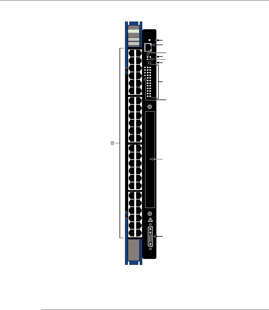
Figure 1-1 7H4385-49 DFE-Platinum Module
1OFFLINE/RESET switch 7GROUP STATUS LEDs
2RJ45 COM port 8GROUP SELECT LEDs
3MGMT LED 9NEM option slot
4CPU LED 10 48 Vdc ~ 20 A Max. Optional Power Input
5PoE LED connector
6GROUP SELECT switch 11 Ports (1-48), 10/100 Mbps, through RJ45s
1X
G
R
O
U
P
1
G
R
O
U
P
2
11X
13X
23X
OFFLINE/
RESET
COM
CPU
MGMT
GROUP
SELECT
GROUP
1
2
3
4
5
6
7
8
9
10
11
12
POE
14X
24X
G
R
O
U
P
3
25X
35X
26X
36X
G
R
O
U
P
4
37X
47X
38X
48X
1
2
3
4
48V --- 20A MAX
OPTIONAL
POWER INPUT
DFE
7H4385-49
FAST ENET
Â
Ã
Å
Á
À
Æ
Ä
Ç
È
É

Connectivity
DFE-Platinum Series Hardware Installation Guide 1-5
Connectivity
The7H4385‐49DFEmodulesupportsupto48,10BASE‐T/100BASE‐TXswitchedports
connectedthrough48fixedfrontpanelconnectors,andthebridgefunctionbetween
FTM1andFTM2connectionsonthechassisbackplane.Thisenablesbridgingbetween
6x1xxx,6x2xxx,6x3xxx,and7x4xxxseriesmodulesinstalledinthesameMatrix E7
chassis.IfaNEMisinstalled,additionalconnectionsarealsoavailable,dependingonthe
NEMmodel.
ThefixedfrontpanelportscanalsosupportconnectionstoPoE‐compliantPDswhenthe
moduleisconnectedtoanexternalN‐PoEPowersystem.
Management
Managementofthemodulecanbeeitherin‐bandorout‐of‐band.In‐bandremote
managementispossibleusingTelnet,Enterasys Networks’NetSight®management
application,orWebView™application.Out‐of‐bandmanagementisprovidedthrough
theRJ45COM(Communication)portonthefrontpanelusingaVT100terminalora
VT100terminalemulator.
Switch Configuration Using WebView
Enterasys Networks’HTTP‐basedWebmanagementapplication(WebView)isan
intuitivewebtoolforsimplemanagementtasks.
Switch Configuration Using CLI Commands
TheCLIcommandsenableyoutoperformmorecompleteswitchconfiguration
managementtasks.
ForCLIcommandsetinformationandhowtoconfigurethemodule,refertotheEnterasys
MatrixDFE‐PlatinumSeriesConfigurationGuide.
Standards Compatibility
TheDFEmodulesarefullycompliantwiththeIEEE802.3‐2002,802.3ae‐2002,802.1D‐
1998,802.3af‐2003,and802.1Q‐1998standards.TheDFEmoduleprovidesIEEE
802.1D‐1998SpanningTreeAlgorithm(STA)supporttoenhancetheoverallreliabilityof
thenetworkandprotectagainst“loop”conditions.
Note: The 7H4385-49 does not support both the FTM bridge function and an optional
network expansion module at the same time. With a NEMinstalled, the FTM bridging
function is disabled. All ports remain active in either case.

Secure Networks Policy Support
1-6 Introduction
Secure Networks Policy Support
PolicyEnabledNetworkingmanagestheallocationofnetworkinginfrastructure
resourcesinasecureandeffectivemanner.UsingSecureNetworksPolicy,anIT
AdministratorcanpredictablyassignappropriateresourcestotheUsers,Applications,
andServicesthatusethenetwork;whileblockingorcontainingaccessforinappropriate
orpotentiallydangerousnetworktraffic.Usingthistechnologyitispossible,forthefirst
time,toalignITserviceswiththeneedsofspecificusersandapplications,andtoleverage
thenetworkasakeycomponentoftheorganization’ssecuritystrategy.
TheSecureNetworksPolicyArchitectureconsistsof3components:ClassificationRules,
NetworkServices,andBehavioralProfiles.Thesearedefinedasfollows:
• ClassificationRulesdeterminehowspecifictrafficflows(identifiedbyLayer2,Layer
3,andLayer4informationinthedatapacket)aretreatedbyeachSwitchorRouter.In
general,ClassificationRulesareappliedtothenetworkinginfrastructureatthe
networkedge/ingresspoint.
•NetworkServicesarelogicalgroupsofClassificationRulesthatidentifyspecific
networkedapplicationsorservices.Usersmaybepermittedordeniedaccesstothese
servicesbasedontheirrolewithintheorganization.Priorityandbandwidthrate
limitingmayalsobecontrolledusingNetworkServices.
•BehavioralProfiles(orroles)areusedtoassignNetworkServicestogroupsofusers
whosharecommonneeds–forexampleExecutiveManagers,HumanResources
Personnel,orGuestUsers.Access,resources,andsecurityrestrictionsareappliedas
appropriatetoeachBehavioralProfile.Avarietyofauthenticationmethodsincluding
802.1X,EAP‐TLS,EAP‐TTLS,andPEAPmaybeusedtoclassifyandauthorizeeach
individualuser;andtheITAdministratormayalsodefineaBehavioralProfileto
applyintheabsenceofanauthenticationframework.
LANVIEW Diagnostic LEDs
LANVIEWdiagnosticLEDsserveasanimportanttroubleshootingaidbyprovidingan
easywaytoobservethestatusofindividualportsandoverallnetworkoperations.
DFE-Platinum Series Hardware Installation Guide 2-1
2
Network Requirements
Beforeinstallingthemodule,reviewtherequirementsandspecificationsreferredtoin
thischapterconcerningthefollowing:
Thenetworkinstallationmustmeettherequirementstoensuresatisfactoryperformance
ofthisequipment.Failuretodosowillproducepoornetworkperformance.
Link Aggregation
LinkAggregationisamethodofgroupingmultiplephysicalportsonanetworkdevice
intoonelogicallinkaccordingtotheIEEE802.3ad‐2002standard.BecauseLink
Aggregationisstandardsbased,itallowsforautomaticconfigurationwithmanual
overrides(ifapplicable),andcanoperateon10Mbps,100Mbps,or1000MbpsEthernet
fullduplexports.Thusthenetworkadministratorcancombineagroupoffive100Mbps
portsintoalogicallink(trunk)thatfunctionsasasingle500Mbpsport.Aslongasthe
DFEmodulesagreeonwhichportsareinthetrunk,therearenoproblemswithlooping,
andtheSpanningTreecantreatthistrunkasasingleport.
For information about... Refer to page...
Link Aggregation 2-1
Module Placement in a Matrix E7 Chassis 2-2
FTM Bridge Function and Optional Interface Module 2-2
10BASE-T Network 2-2
100BASE-TX Network 2-3
The Enterasys Matrix DFE-Platinum Series Configuration Guide and the Cabling Guide
referred to in the following sections can be found on the Enterasys Networks World Wide
Web site: http://www.enterasys.com/support/manuals
Refer to “Related Documents” on page xvi for additional information.

Module Placement in a Matrix E7 Chassis
2-2 Network Requirements
Innormalusage(andtypicalimplementations)thereisnoneedtoenable/disableportsfor
LinkAggregation.Thedefaultvalueswillresultinthemaximumnumberofaggregations
possible.Iftheswitchisplacedinaconfigurationwithitspeersnotrunningtheprotocol,
noaggregationswillbeformedandtheDFEmoduleswillfunctionnormally(thatis,
SpanningTreewillblockredundantpaths).
FordetailsaboutthecommandsinvolvedwithconfiguringtheLinkAggregation
function,refertotheEnterasysMatrixDFE‐PlatinumSeriesConfigurationGuide.
Module Placement in a Matrix E7 Chassis
Ifyouwanttomix6x1xxx,6x2xxx,6x3xxx,and7H43xx‐xxseriesmodulesinthesame
Matrix E7chassis,andsuccessfullybridgedatatraffictosomeorallmodulesinthe
chassis,itisnecessarytohaveabridgingmodule(suchasthe7H4385‐49)installed,andto
followthemoduleplacementrulesdescribedin“ModulePlacementandInstallation
Rules”onpage 3‐4.
FTM Bridge Function and Optional Interface Module
The7H4385‐49DFE‐PlatinummoduledoesnotsupportboththeFTMbridgingfunction
andanoptionalNEMatthesametime.WithanoptionalNEMinstalled,theFTM
bridgingfunctionisdisabled.Ineitherofthesecases,allportsofthe7H4385‐49remain
active.
10BASE-T Network
Whenconnectinga10BASE‐TsegmenttoanyoftheRJ45fixedfront‐panelportsofthe
7H4385‐49,ensurethatthenetworkmeetstheEthernetnetworkrequirementsofthe
IEEE 802.3‐2002standardfor10BASE‐Tand802.3af‐2003standardforPowerover
Ethernet(PoE)powersourcingapplicationsoverEthernetcabling.Formoreinformation
aboutPoE,refertoAppendix C.
Note: If a port is to operate at 100 Mbps, Category 5 cabling must be used. Category 3
cabling does not meet 100 Mbps specifications. For 10 Mbps operation only, Category 3
or Category 5 cabling can be used. Refer to the “100BASE-TX Network” on page 2-3 for
information about 100BASE-TX networks and cabling.

100BASE-TX Network
DFE-Platinum Series Hardware Installation Guide 2-3
100BASE-TX Network
Thefixedfrontpanelportsofthe7H4385‐49 provideaconnectionthatsupportsCategory
5UTPcabling.Thedeviceattheotherendofthetwistedpairsegmentmustmeet
IEEE 802.3‐2002100BASE‐TXFastEthernetnetworkrequirementsforthedevicesto
operateat100 Mbps.Thefixedfront‐panelportsalsosupportthe802.3af‐2003standard
forPoweroverEthernet(PoE)powersourcingapplicationsoverexistingcabling.For
moreinformationaboutPoE,refertoAppendix C.
Note: The fixed ports of the module support Category 5 UTP cabling with an impedance
between 85 and 111 ohms for 100 Mbps operation.
The module is capable of operating at either 10 or 100 Mbps. The module automatically
senses the speed of the other device and adjusts its speed accordingly.

100BASE-TX Network
2-4 Network Requirements
DFE-Platinum Series Hardware Installation Guide 3-1
3
Installation
Thischapterprovidestheinstructionstoinstallthe7H4382‐49DFE module.Followthe
orderofthesectionslistedbelowtocorrectlyinstalltheDFE module.
Electrical Hazard: Only qualified personnel should perform installation procedures.
Riesgo Electrico: Solamente personal calificado debe realizar procedimientos de
instalacion.
Elektrischer Gefahrenhinweis: Installationen sollten nur durch ausgebildetes und
qualifiziertes Personal vorgenommen werden.
Important Notice
Read the Release Notes shipped with the DFE module to check for any exceptions to the supported
features and operation documented in this guide.
For information about... Refer to page...
Installation Site Requirement 3-2
Unpacking the DFE Module 3-2
Installing Optional Network Expansion Module (NEM) 3-3
Backplane Connections and Installation Rules 3-3
Preparing to Install into a Matrix E7, N1, N3, N5, or N7 Chassis 3-7
Connecting 48 Vdc Power for PoE Operation 3-14
Connecting to the Network 3-15
Connecting to COM Port for Local Management 3-20
Completing the Installation 3-26
Installation Site Requirement
3-2 Installation
Installation Site Requirement
The7H4385‐49mustbeinstalledinaMatrix E7,N1,N3,N5,orN7chassislocatedina
RestrictedAccessLocation(RAL).Thislocationshouldonlybeaccessiblebypeoplethat
havebeentrainedoraretechnicallycompetentenoughtobeawareofpotentialrisksof
accessingthehazardousareasofthechassis.Locationssuchasalockedwiringclosetor
lockedcabinetmeetthisrequirement.
Unpacking the DFE Module
UnpacktheDFEmoduleasfollows:
1. OpentheboxandremovethepackingmaterialprotectingtheDFE module.
2. VerifythecontentsofthecartonaslistedinTable 3‐1.
3. Removethetapesealonthenon‐conductivebagtoremovetheDFE module.
4. PerformavisualinspectionoftheDFE moduleforanysignsofphysicaldamage.
ContactEnterasys Networksifthereareanysignsofdamage.Referto“GettingHelp”
onpage xviiifordetails.
Warning: Install this module in a Matrix E7, N1, N3, N5, or N7 chassis that has been
installed in a Restricted Access Location only. Access to the equipment by users must be
restricted through the use of a tool or lock and key or other means of security and is
controlled by the authority responsible for the location.
Advertencia: Instalar este modulo en un Matrix E7, N1, N3, N5, o N7 que ha sido
localizado en un lugar de Acceso Restringido. Aceso al equipo debe ser restringido por el
responsable del sitio.
Warnhinweis: Installieren Sie dieses Modul nur in einem E7, N1, N3, N5, oder N7
Chassis, wenn sich diese in einer zugangsgeschützten Umgebung befinden. Der Bereich
zu den Komponenten sollte durch ein Schloß, einen Schlüssel oder sonstigen
Sicherungen geschützt und durch einen Verantwortlichen kontrolliert werden.
Table 3-1 Contents of 7H4385-49 Module Carton
Item Quantity
7H4385-49 1
Installation Guide 1
Customer Release Notes 1

Installing Optional Network Expansion Module (NEM)
DFE-Platinum Series Hardware Installation Guide 3-3
Installing Optional Network Expansion Module (NEM)
RefertoyourreleasenotesortheEnterasys Networkswebsiteforthelatestavailable
networkexpansionmodule.
APhillipsscrewdriverisrequiredtoinstallanoptionalnetworkexpansionmoduleinto
the7H4385‐49.
InstallingaNEMinvolves
•removingthesafetycover
•removingthecoverplatefromtheDFEmodule(7H4385‐49),
• attachingthenetworkexpansionmodule,and
•replacingthesafetycover.
RefertotheinstallationinstuctionsshippedwiththeNEMfordetails.
Backplane Connections and Installation Rules
ThefollowingsectionsdescribetheFTM1andFTM2backplaneconnections,andthe
hardwareconfigurationruleswheninstallingfirst(6x1xx),second(6x2xx),third(6x3xx),
andfourth(7xxxxx)generationmodulesintothesameMatrix E7chassis.
FTM1 and FTM2 Connectivity
TheMatrix E7(6C107)chassishasbackplanesreferredtoasFTM1andFTM2.The7xxxxx
DFE modulesuseFTM2forhighspeedcommunicationtoeachotherandoperateasone
switchingunitwithasingleIPaddress.Thetrafficthroughthesemodulesdoesnot
connecttoFTM1exceptthroughanFTMbridgingmodulesuchasthe7H4382‐25,
7H4382‐49,7H4383‐49,orthe7H4385‐49.InstallationGuidesforthesebridgingmodules
arelocatedontheEnterasysNetworksWorldWideWebsite:http://www.enterasys.com/
support/manuals.
Note: Install any optional equipment before proceeding to “Backplane Connections and
Installation Rules” on page 3-3 for an explanation of the rules to install different series
modules in a Matrix E7 chassis.
Note: A lowercase x indicates the general use of an alphanumeric character (for example,
6x1xx, the x’s indicate a combination of numbers or letters).
Backplane Connections and Installation Rules
3-4 Installation
TheseDFE moduleshaveconnectionstobothFTM1andFTM2backplanes,enablingthem
torouteframesbetweenthetwobackplanesandallmodulesinthe6C107chassis.
However,theolderfirst(6x1xx),second(6x2xx),andthird(6x3xx)generationmodules
arestillmanagedusingtheirownLocalManagementandarenotsubjecttomanagement
bytheDFE modulemanagemententity.
TheMatrix N1(7C111),Matrix N3(7C103)andMatrix N7(7C107)chassishaveonlyFTM2
connectionsandsupportonlyDFE modules.TheMatrix N5(7C105‐P)hasFTM2
connectionsandalsosupportsPoE‐compliantDFE modules.
Module Placement and Installation Rules
TheDFE‐PlatinummodulescanbeinstalledinaMatrix E7(referto“Matrix E7Chassis
ModulePlacement,”below,forplacementrules),Matrix N1,Matrix N3,Matrix N5,or
Matrix N7chassis.TheMatrix N1,Matrix N3,Matrix N5,andMatrix N7chassissupport
onlyDFESeriesmodulesandtherearenoparticularrulesforinstallingmodules.
Matrix E7 Chassis Module Placement
DependingonthemodulesbeinginstalledintheMatrix E7chassisandtohelpensure
properoperation,considerthefollowingexamplesandrulesformoduleplacementinthe
chassis.Figure 3‐1showssixexamplesofchassismoduleplacement.Theseexamplesare
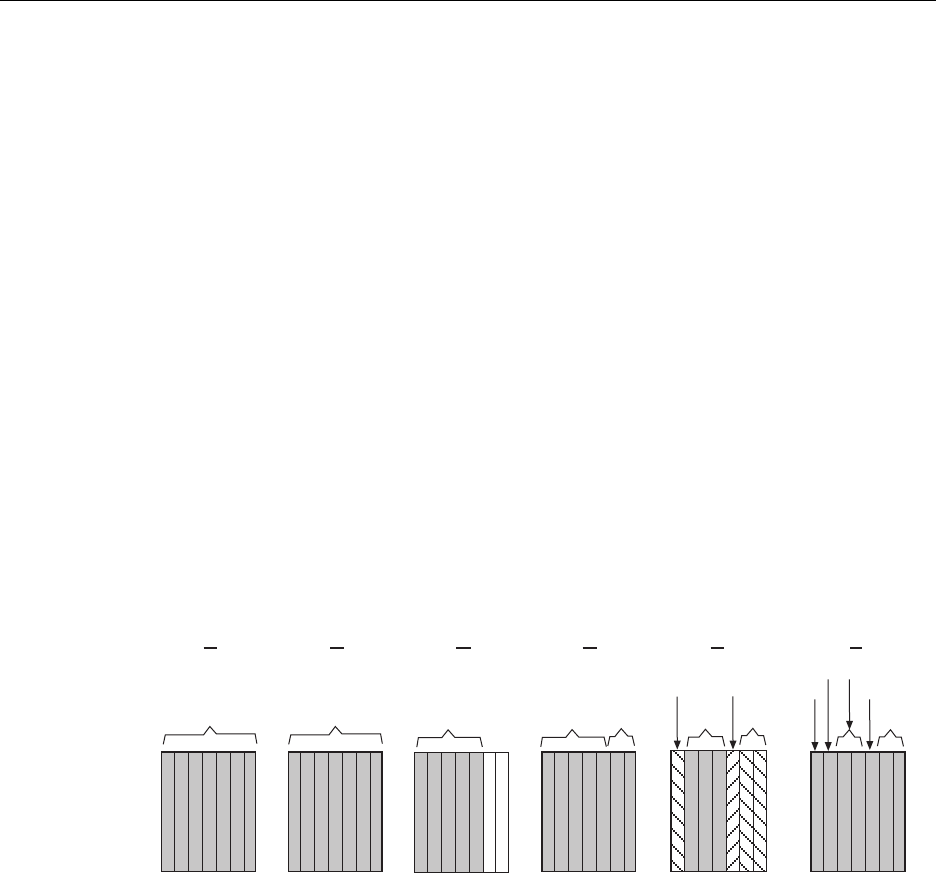
describedbelowalongwiththeapplicablemoduleplacementrule.
Figure 3-1 Examples, Module Placement in Matrix E7 Chassis
Example 1 (Figure 3-1, A)
ShowsthechassisfullypopulatedwithDFE modules(7xxxxx).Thesemodules
communicatewitheachotherviatheFTM2chassisbackplaneandactasasingle
switchingentitywithoneIPaddress.TheDFE modulesareconfiguredusingaCommand
LineInterfacesetofcommands.
Rule:DFE modulescanbeinstalledinanyavailablechassisslotintheMatrix E7chassis.
7XXXXX7H43X-XX
6X3XX
6X3XX
6X2XX 6X1XX
1 2 3 4 5 6 7
6X1XX
6X2XX
+
6X3XX 6X3XX
1 2 3 4 5 6 7
6X1XX
6X2XX
1 2 3 4 5 6 7
6X3XX
1 2 3 4 5 6 7
7XXXXX
1 2 3 4 5 6 7 1 2 3 4 5 6 7
6X3XX
6X3XX
6X2XX
7XXXXX
6X1XX
A EDCB F

Backplane Connections and Installation Rules
DFE-Platinum Series Hardware Installation Guide 3-5
Example 2 (Figure 3-1, B)
Showsthechassisfullypopulatedwiththirdgenerationmodules(6x3xx).Thesemodules
canalsobeinstalledinanyavailablechassisslotintheMatrix E7chassis,butoperateas
individualmoduleswithseparateIPaddresses.EachmoduleisconfiguredusingLocal
Management.
Rule:The6x3xxmodulescanbeinstalledinanyavailablechassisslotintheMatrix E7
chassis.
Example 3 (Figure 3-1, C)
Showschassisslots1through5populatedwithfirstandsecondgenerationmodules
(6x1xxand6x2xx).Ifa6x1xxor6x2xxseriesmoduleisinstalledinslot6or7,itwill
operateinstandalonemode(nobackplaneconnectivity).Likethe6x3xxmodules,the
6x1xxand6x2xxmodulesoperateasindividualmoduleswithseparateIPaddresses,and
eachoneisconfiguredusingLocalManagement.
Rule:The6x1xxand6x2xxmodulescancommunicatewitheachotherwhentheyare
installedinchassisslots1through5intheMatrix E7chassis.Ifinstalledinslot6or7,they
operateinstandalonemode.
Example 4 (Figure 3-1, D)
Showschassisslots1through5populatedwithamixof6x1xx,6x2xx,and6x3xxmodules
andonlythirdgenerationmodulesinslots6and7.
Inthismodulearrangement,the6x3xxmoduleprovidesaproxybridge,whichenables
the6x1xxand6x2xxmodulestocommunicatewith6x3xxmodulesinslot6or7.Ifmore
thanone6x3xxmoduleisinstalledinslots1to5,themoduleinthelowestnumberedslot
performstheproxyfunctionforslots6and7.Therefore,ifa6x3xxmoduleisalready
performingtheproxyfunction,andanother6x3xxmoduleisinsertedintoalower
numberedslot,connectivitywillbetemporarilyinterrupted,asthenewboardtakesover
theproxyfunction.Whena6x3xxmoduleinalowernumberedslotisremoved,andthere
isa6x3xxmoduleinahighernumberedslot,communicationisnotinterrupted.
ForLocalManagement,pluggingtheLocalManagementconnectionintothe6x3xx
moduleswillallowmanagementconnectionstoall6x1xx,6x2xx,and6x3xxmodules.If
theLocalManagementconnectionistoa6x1xxor6x2xxboard,onlythemodulesinthe
firstfiveslotswillberecognizedbythemanagementclient.
Rule:Theremustbeatleastone6x3xxmoduleinslots1through5toenable
communicationsbetweenthe6x1xx,6x2xx,and6x3xxmodules.

Backplane Connections and Installation Rules
3-6 Installation
Example 5 (Figure 3-1, E)
Showschassisslots1and5populatedwith6x2xxand6x1xxmodules,respectively;slots2
through4withDFE moduleswithoutabridgingmodule;andslots6and7with6x3xx
modules.
Inthismodulearrangement,the6x2xxand6x1xxmodulesinslots1and5canonly
communicatewitheachother,becausethereisno6x3xxmoduleinoneofthefirstfive
slotstoserveastheproxybridgetocommunicatewiththe6x3xxmodulesinslots6and7.
The7x4xxxDFE modulesinslots2,3,and4willoperateunderoneIPaddress.Sincethere
isnoDFEbridgingmodule,theDFE moduleswillnotcommunicatewithanyother
modulesinthechassis.
Rule:Inthisexample,theremustbeatleastone6x3xxseriesmodule,andabridging
moduleinanyoftheslots1through5toenablecommunicationsbetweenallgenerations
ofmodulesinthechassis.
Example 6 (Figure 3-1, F)
ThemodulearrangementinthisexampleissimilartotheoneshowninFigure 3‐1,E and
describedinExample5.Theonlydifferenceisthatoneofthebridgingmodules
(7H4382‐25,7H4382‐49,7H4383‐49,or7H4385‐49)isinstalledinslot2,enablingall
modulestocommunicatewitheachother.The7H4382‐49isusedinthisexample.
Rule:Inthisexample,thebridgingmoduleservesasboththeFTM1‐to‐FTM2bridgeand
thefive‐to‐sevenslotproxybridge.The6x3xxdoesnotserveasaproxybridgeinthis
configurationbecausethebridgingmoduleisinaslotwithalowernumber.

Preparing to Install into a Matrix E7, N1, N3, N5, or N7 Chassis
DFE-Platinum Series Hardware Installation Guide 3-7
Preparing to Install into a Matrix E7, N1, N3, N5, or N7 Chassis
ToinstallanymoduleintotheMatrix E7 chassis,referto“BackplaneConnectionsand
InstallationRules”onpage 3‐3tofamiliarizeyourselfwiththeFTM1andFTM2backplane
connectionsandthemodulehardwareinstallationrules.Thenproceedasfollowsto
preparetheDFE moduleforinstallation.
ToinstallaDFEmoduleintoaMatrix E7,Matrix N1,Matrix N3,Matrix N5, or Matrix N7
chassis,proceedasfollowstopreparethemoduleforinstallation.
1. Removetheblankpanelcoveringtheslotinwhichthemodulewillbeinstalled.All
otherslotsmustremaincoveredtoensureproperairflowforcooling.(Savetheblank
plateintheeventyouneedtoremovethemodule.)
2. Removethemodulefromtheshippingbox.(Savetheboxandpackingmaterialsin
theeventthemoduleneedstobereshipped.)
3. Locatetheantistaticwriststrapshippedwiththechassis.Attachtheantistaticwrist
straptoyourwristandplugthecablefromtheantistaticwriststrapintotheESD
groundingreceptacleattheupperrightcornerofthechassis.
4. Removethemodulefromtheplasticbag.(Savethebagintheeventthemodulemust
bereshipped.)ObserveallprecautionstopreventdamagefromElectrostatic
Discharge(ESD).
Caution: Failure to observe static safety precautions could cause damage to the module.
Follow static safety handling rules and wear the antistatic wrist strap.
Do not cut the non-conductive bag to remove the module. Sharp objects contacting the
board or components can cause damage.
Precaución: Si no toma las medidas de seguridad necesarias para evitar descargas de
electricidad estática, es posible que el módulo se dañe. Siga los consejos de seguridad
para la manipulación del producto y no olvide utilizar la pulsera antiestática.
No corte la bolsa antiestática para sacar el módulo. Tenga en cuenta que si algún objeto
cortante entra en contacto con la placa o con los componentes, éstos podrían dañarse.
Warning: Install this module in a Matrix E7, N1, N3, N5, or N7 chassis that has been
installed in a Restricted Access Location only. Access to the equipment by users must be
restricted through the use of a tool or lock and key or other means of security and is
controlled by the authority responsible for the location.
Advertencia: Instalar este modulo en un Matrix E7, N1, N3, N5, o N7 que ha sido
localizado en un lugar de Acceso Restringido. Aceso al equipo debe ser restringido por el
responsable del sitio.
Warnhinweis: Installieren Sie dieses Modul nur in einem E7, N1, N3, N5, oder N7
Chassis, wenn sich diese in einer zugangsgeschützten Umgebung befinden. Der Bereich
zu den Komponenten sollte durch ein Schloß, einen Schlüssel oder sonstigen
Sicherungen geschützt und durch einen Verantwortlichen kontrolliert werden.

Preparing to Install into a Matrix E7, N1, N3, N5, or N7 Chassis
3-8 Installation
5. Examinethemodulefordamage.Ifanydamageexists,DONOTinstallthemodule.
ImmediatelycontactEnterasysNetworks.Referto“GettingHelp”onpage xviii.
6. Toinstalla7H4385‐49intoaMatrix E7or Matrix N7,proceedto“Installingthe
7H4385‐49intoaMatrix E7orMatrix N7Chassis”onpage 3‐8.ForMatrix N1,
Matrix N3,orMatrix N1,referto“Installingthe7H4385‐49intoMatrixN1,N3,orN5
Chassis”onpage 3‐11.
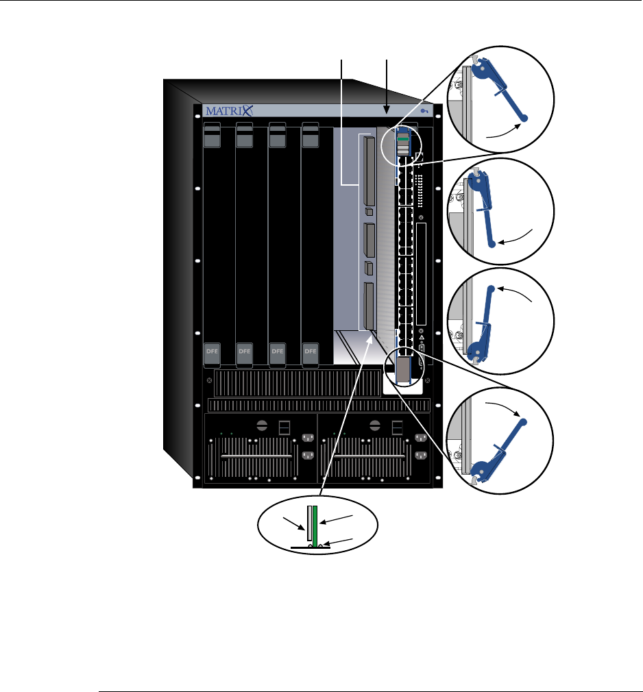
Installing the 7H4385-49 into a Matrix E7 or Matrix N7 Chassis
Toinstallthe7H4385‐49,refertoFigure 3‐2andproceedasfollows:
1. Preparethechassisasdescribedin“PreparingtoInstallintoaMatrix E7,N1,N3,N5,
orN7Chassis”onpage 3‐7.
2. Locatethechassiscardguidesthatlineupwiththeslotnumberinwhichthemodule
willbeinstalled.Makesurethemodulelockingleversareintheopenposition(top
andbottom).
Caution: To prevent damaging the backplane connectors in the following step, take care
that the module slides in straight and properly engages the backplane connectors.
Ensure that the top lever lines up with the desired slot number located on the front panel
of the chassis. Refer to Figure 3-2.
Precaución: Para evitar que se dañen los conectores del panel posterior en el siguiente
paso, intente deslizar el módulo en forma recta y verifique que se enganche
correctamente en los conectores de panel posterior.
Asegúrese de que la palanca superior esté alineada con respecto al número de ranura
correspondiente ubicado en el panel frontal del chasis. Consulte en Figure 3-2.
Electrical Hazard: To prevent exposure to an energy hazard in a 7H4385-49 connected
to an external N-POE Power System, disconnect the 48-Vdc power cable from the 48-Vdc
input connector before servicing or removing the 7H4385-49.
Riesgo Eléctrico: Para prevenir la exposicion a un riesgo electrico en una tarjeta
7H4385-49 conectada a un sistema externo de energia N-POE Power System,
desconectar el cable de poder de 48-Vdc del conector de entrada 48-Vdc antes de dar
servicio o remover la tarjeta 7H4385-49.
Elektrischer Gefahrenhinweis: Um den Schutz vor el. Schäden des Moduls
(7H4385-49) zu gewähleisten, bei Verwendung der N-POE Systeme, sollte dies bevor
man dieses entnimmt oder Servicearbeiten daran vornimmt, vom 48-Vdc Stecker getrennt
werden.

Preparing to Install into a Matrix E7, N1, N3, N5, or N7 Chassis
DFE-Platinum Series Hardware Installation Guide 3-9
3. Alignthemodulecardbetweentheupperandlowercardguidesofthedesiredslot
andslideitintothechassis,takingcarethatthemoduleslidesinstraight.SeeCaution
below.
4. Slidethemoduleintotheslotuntilyoucanengagethetopandbottomlockinglevers.
5. RefertotheCautionnoteabove,thenrotatethetwoleversintotheclosedposition.
6. Ifthechassisinwhichthemoduleisinstalledwaspowereddownfortheinstallation,
turnthepowersupplieson.ChecktoseethatthemoduleCPULEDsettlesatsolid
greenafterafewminutes.IftheLEDdoesnotturnsolidgreen,refertoChapter 4for
troubleshootingdetails.
Caution: Due to the amount of force needed to properly seat the module connectors into
the backplane connectors, it is best to apply force to the end of the levers to insert (or
eject) the module. Otherwise, damage could result to the module and chassis.
Precaución: Para colocar los conectores del módulo en los conectores del panel
posterior correctamente es necesario hacer bastante fuerza, por ello, para insertar o
quitar el módulo, se recomienda concentrar la fuerza en el extremo de las palancas. Si no
lo hace, podría dañar el módulo y el chasis.
Caution: In step 5, do not force the locking levers to the point that they touch the face of
the front panel. Forcing the locking levers to this point could damage the module and
chassis.
Precaución: En el paso 5, tenga cuidado de no llevar las palancas de cierre a un punto
en donde estén en contacto con el panel frontal. Si lo hace, podría dañar el módulo y/o el
chasis.
Preparing to Install into a Matrix E7, N1, N3, N5, or N7 Chassis
3-10 Installation
Figure 3-2 Installing Module into Matrix E7 or N7 Chassis (Matrix E7 shown)
1Card guides 7Backplane connectors
2Slot number 6 (Left-most slot is 1) • Top two connectors (power and FTM2
3Module card • Bottom two connectors (power and FTM1)
4Metal back panel (no bottom connectors in Matrix N7chassis)
5Upper/lower locking tabs (in proper open
position)
6Upper/lower locking tab (in closed
position)
1
SERIES
E7
4567
23
50/60Hz
LINE
100-125V~12A
200-240V~6A
50/60Hz
LINE
100-125V~12A
200-240V~6A
ACON
1
0
POWER FAN
PS1
50/60Hz
LINE
100-125V~12A
200-240V~6A
50/60Hz
LINE
100-125V~12A
200-240V~6A
ACON
1
0
POWER FAN
PS2
1X
G
R
O
U
P
1
G
R
O
U
P
2
11X
13X
23X
OFFLINE/
RESET
COM
CPU
MGMT
GROUP
SELECT
GROUP
1
2
3
4
5
6
7
8
9
10
11
12
POE
12X
14X
24X
G
R
O
U
P
3
25X
35X
26X
36X
G
R
O
U
P
4
37X
47X
38X
48X
DFE
7H4385-49
FAST ENET
1
2
3
4
48V --- 20A MAX
OPTIONAL
POWER INPUT
Ä
Ä
Å
Å
ÁÆ
ÃÂ
À
Preparing to Install into a Matrix E7, N1, N3, N5, or N7 Chassis
DFE-Platinum Series Hardware Installation Guide 3-11
Installing the 7H4385-49 into Matrix N1, N3, or N5 Chassis
ADFE modulecanbeinstalledinanyavailablechassisslot(1through3)intheMatrix N3
chassis,orslots1through5intheMatrix N5chassis,orintothesingleslotofthe
Matrix N1chassis.AllchassishavehorizontalslotsforDFE modules.Toinstallthe
moduleintotheMatrix N3,N5,orN1chassis, refertoFigure 3‐3andproceedasdescribed
in“PreparingtoInstallintoaMatrix E7,N1,N3,N5,orN7Chassis”onpage 3‐7.
1. PreparetheDFE moduleusing theproceduredescribedin“PreparingtoInstallintoa
Matrix E7,N1,N3,N5,orN7Chassis”onpage 3‐7.
2. Locatethechassiscardguidesthatlineupwiththeslotnumberinwhichthemodule
willbeinstalled.Makesurethemodulelockingleversareintheopenposition(top
andbottom).
Caution: Failure to observe static safety precautions could cause damage to the module.
Follow static safety handling rules and wear the antistatic wrist strap.
Do not cut the non-conductive bag to remove the module. Sharp objects contacting the
board or components can cause damage.
Precaución: Si no toma las medidas de seguridad necesarias para evitar descargas de
electricidad estática, es posible que el módulo se dañe. Siga los consejos de seguridad
para la manipulación del producto y no olvide utilizar la pulsera antiestática.
No corte la bolsa antiestática para sacar el módulo. Tenga en cuenta que si algún objeto
cortante entra en contacto con la placa o con los componentes, éstos podrían dañarse.
Caution: When setting the locking levers to the closed position, do not try to force the
locking levers to the point that they touch the face of the front panel. Forcing the locking
levers to this point could damage the module and chassis.
Precaución: Al mover las palancas a la posición de cerrado, tenga cuidado de no
llevarlas a un punto en donde estén en contacto con el panel frontal. Si lo hace, podría
dañar el módulo o el chasis.
Electrical Hazard: To prevent exposure to an energy hazard in a 7H4385-49 connected
to an external N-POE Power System, disconnect the 48-Vdc power cable from the 48-Vdc
input connector before servicing or removing the 7H4385-49.
Riesgo Eléctrico: Para prevenir la exposicion a un riesgo electrico en una tarjeta
7H4385-49 conectada a un sistema externo de energia N-POE Power System,
desconectar el cable de poder de 48-Vdc del conector de entrada 48-Vdc antes de dar
servicio o remover la tarjeta 7H4385-49.
Elektrischer Gefahrenhinweis: Um den Schutz vor el. Schäden des Moduls
(7H4385-49) zu gewähleisten, bei Verwendung der N-POE Systeme, sollte dies bevor
man dieses entnimmt oder Servicearbeiten daran vornimmt, vom 48-Vdc Stecker getrennt
werden.

Preparing to Install into a Matrix E7, N1, N3, N5, or N7 Chassis
3-12 Installation
3. Alignthemodulecardbetweentheupperandlowercardguidesofthedesiredslot
andslideitintothechassis,takingcarethatthemoduleslidesinstraight.SeeCaution
below.
4. Slidethemoduleintotheslotuntilyoucanengagethetopandbottomlockinglevers.
5. RefertotheCautionnoteabove,thenrotatethetwoleversintotheclosedposition.
6. Ifthechassisinwhichthemoduleisinstalledwaspowereddownfortheinstallation,
turnthepowersupplieson.ChecktoseethatthemoduleCPULEDsettlesatsolid
greenafterafewminutes.IftheLEDdoesnotturnsolidgreen,refertoChapter 4for
troubleshootingdetails.
Caution: Due to the amount of force needed to properly seat the module connectors into
the backplane connectors, it is best to apply force to the end of the levers to insert (or
eject) the module. Otherwise, damage could result to the module and chassis.
Precaución: Para colocar los conectores del módulo en los conectores del panel
posterior correctamente es necesario hacer bastante fuerza, por ello, para insertar o
quitar el módulo, se recomienda concentrar la fuerza en el extremo de las palancas. Si no
lo hace, podría dañar el módulo y el chasis.
Caution: In step 5, do not force the locking levers to the point that they touch the face of
the front panel. Forcing the locking levers to this point could damage the module and
chassis.
Precaución: En el paso 5, tenga cuidado de no llevar las palancas de cierre a un punto
en donde estén en contacto con el panel frontal. Si lo hace, podría dañar el módulo y/o el
chasis.
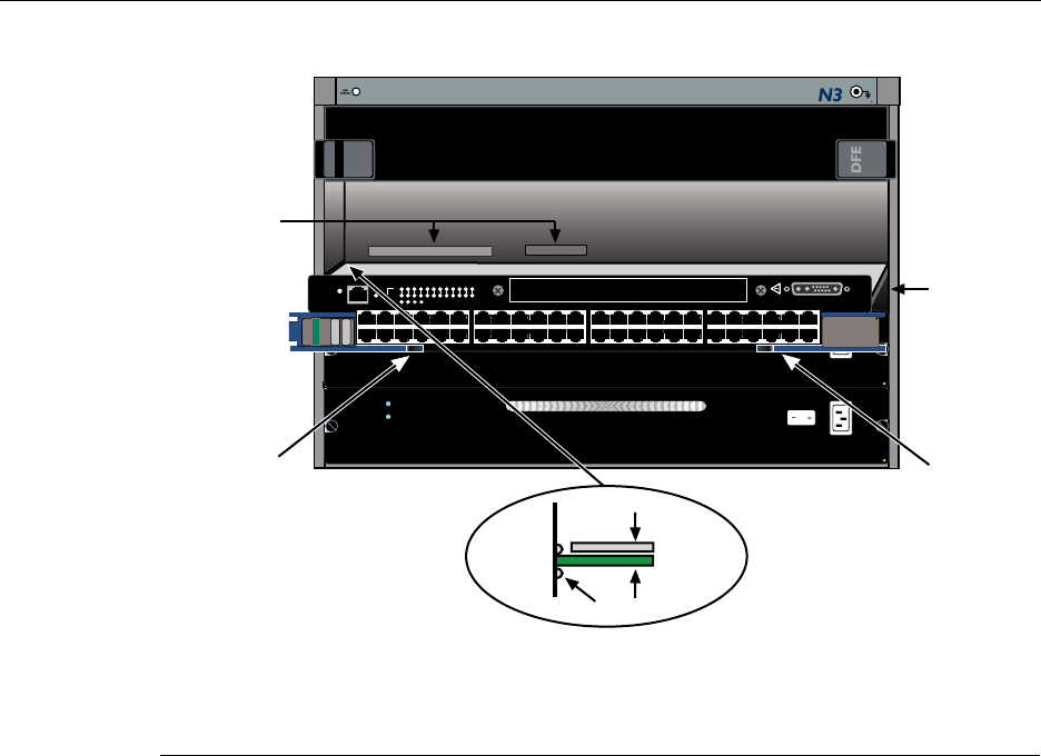
Preparing to Install into a Matrix E7, N1, N3, N5, or N7 Chassis
DFE-Platinum Series Hardware Installation Guide 3-13
Figure 3-3 Installing Module into Matrix N3, N5, or N1 Chassis (N3 shown)
1Card guides 5Upper locking tab (shown in closed position)
2Slot 1 (Top slot is slot 3.) 6Lower locking tab (shown in closed position)
3Module card 7FTM2 and power backplane connectors
4Metal back panel
7C203-1
REDUNDANCY
PWR
100-125V~12.0A
200-240V~6.0A
50/60 Hz
7C203-1
REDUNDANCY
PWR
100-125V~12.0A
200-240V~6.0A
50/60 Hz
1X
G
R
O
U
P
1
G
R
O
U
P
2
11X
13X
23X
OFFLINE/
RESET
COM
CPU
MGMT
GROUP
SELECT
GROUP
1
2
3
4
5
6
7
8
9
10
11
12
POE
12 X
14X
24X
G
R
O
U
P
3
25X
35X
26X
36X
G
R
O
U
P
4
37X
47X
38X
48X
DFE
7H4385-49
FAST ENET
1
2
3
4
48V --- 20A MAX
OPTIONAL
POWER INPUT
Á
Æ
ÄÅ
Â
Ã
À
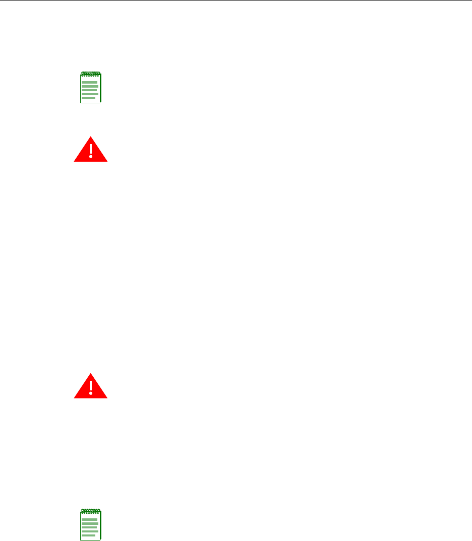
Connecting 48 Vdc Power for PoE Operation
3-14 Installation
Connecting 48 Vdc Power for PoE Operation
TheMatrix N5(7C105‐P)chassisprovides48VdctoconnectedPDs(powereddevices)by
wayofitsbackplaneconnectiontoaPoE‐compliantDFEmodulesuchasthe7H4385‐49.
ForaMatrix E7,(6C107),Matrix N1(7C111),Matrix N3(7C103)andMatrix N7(7C107)
chassis,anoptionalexternalEnterasysMatrixN‐POEPowerSystemisrequiredto
supportPDconnectionstothe7H4385‐49.ThepowerfromtheMatrixN‐POEPower
SystemissuppliedthroughaDCpowercableconnectiontothefront‐panel48Vdc
OptionalPowerconnectoronthe7H4385‐49.
RefertotheMatrixN‐SeriesN‐POEPowerSystemInstallationGuidetoinstallandconnecta
MatrixN‐POEPowerSystemtothe7H4385‐49.
Note: When you install the 7H4382-49 in a Matrix N5 chassis,the7H4382-4948 Vdc
Optional Power Input does not support a connection from an external N-POE Power
System. The 48 Vdc power is supplied through the backplane of the N5 chassis from its
own 48 Vdc power modules. If none of these power modules are installed, then there is no
PoE support.
Warning: The DFE module is shipped with a cover over its 48 Vdc Optional Power Input
connector. Do not remove this cover when the DFE module is installed in an N5 chassis.
This cover is removed only when you connect a 48 Vdc power cable from the Enterasys
N-POE Power System.
Advertencia: El modulo DFE es embarcado con una cubierta sobre su conector de poder
opcional de 48 Vdc. No remover esta cubierta cuando el modulo DFE es instalado en un
chassis N5. Esta cubierta debe removerse unicamente cuando se conecta el cable de
poder de 48 Vdc hacia el Sistema de Enterasys de Energia por Cable (Enterasys N-POE
Power System).
Warnhinweis: Im Auslieferungszustand der DFE Module stülpt eine Schutzkappe über
dem 48V Gleichspannungs-Anschluss, die nur dann abgezogen werden darf, wenn ein
Enterasys N-POE Power System angeschlossen wird. Keinesfalls darf diese Schutzkappe
abgezogen werden, wenn das DFE Modul in einem N5 Chassis installiert wird.
Warning: The 48 V wire harness contains two fuses, F11 and F29. If a fuse needs to be
replaced, it must be done by service personnel only. The fuse must be replaced with the
same Type and Rated fuse 20 A, 400 VDC.
Advertencia: E arnes del cable de 48V contiene dos fusibles, F11 y F29. Si un fusible
requiere ser reemplazado, debe ser hecho por personal de servicio unicamente. El fusible
debe ser reemplazado por uno del mismo tipo y clasificado como fusible de 20 A,
400 VDC.
Warnhinweis: Im Kabelbaum der 48V Zuleitung befinden sich 2 Sicherungen, F11 und
F29. Die Sicherung darf nur duch Fachpersonal getauscht werden und darf auch nur
durch den gleichen Typ ersetzt werden ( 20A / 400VDC ).
Note: If you are planning to install a PoE-compliant DFE module such as the 7H4385-49
in a Matrix N3 (7C103) or Matrix N7 (7C107) chassis, install and connect the Matrix
N-POE Power System before connecting to PDs.

Connecting to the Network
DFE-Platinum Series Hardware Installation Guide 3-15
Connecting to the Network
Thissectionprovidestheproceduresforconnectingunshieldedtwistedpair(UTP)
segmentsfromthenetworkorotherdevicestothe7H4385‐49(“ConnectingUTPCablesto
7H4385‐49”onpage 3‐15).
Connecting UTP Cables to 7H4385-49
ThefixedRJ45frontpanelconnectionsofthe7H4385‐49are10/100Mbpsports.These
portshaveinternalcrossovers,andsupportautomatic‐polaritysensingwhenconfigured
forautomatic‐negotiation.
Ifautomatic‐negotiationisnotactivatedonaport,useastraight‐throughcablewhen
connectingaworkstationtotheport.Whenconnectinganetworkingdevicetotheport,
suchasabridge,repeater,orrouter,useacrossovercable.
Ifaportissetforauto‐negotiation,automatic‐polaritysensingisalsoactivated.
Automatic‐polaritysensingeliminatestheneedforacrossovercable,regardlessifthe
connectionistoanothernetworkdeviceoraworkstation.
TheRJ45fixedfrontpanelconnectorsofthe7H4385‐49alsosupportPoE‐compliant
connectionstoPDs(powereddevices)thatrequire48VdcthroughtheUTPcableto
operate.Whetherthe48VdcisavailablethroughthebackplaneofanN5chassisor
externallyfromanN‐POEPowerSystem,youcanverifyifthereispowerateachportas
describedlaterinthisprocedure.
Note: If the DFE module is being installed in a network using Link Aggregation, there are
rules concerning the network cable and port configurations that must be followed for Link
Aggregation to operate properly. Before connecting the cables, refer to the Enterasys
Matrix DFE-Platinum Series Configuration Guide for the configuration information. For
details on how to obtain manuals, refer to the “Related Documents” in About This Guide.
Note: All RJ45 front panel ports on the 7H4385-49 support Category 5 Unshielded
Twisted Pair (UTP) cabling with an impedance between 85 and 111 ohms. Category 3
cable may be used if the connection is going to be used only for 10 Mbps.
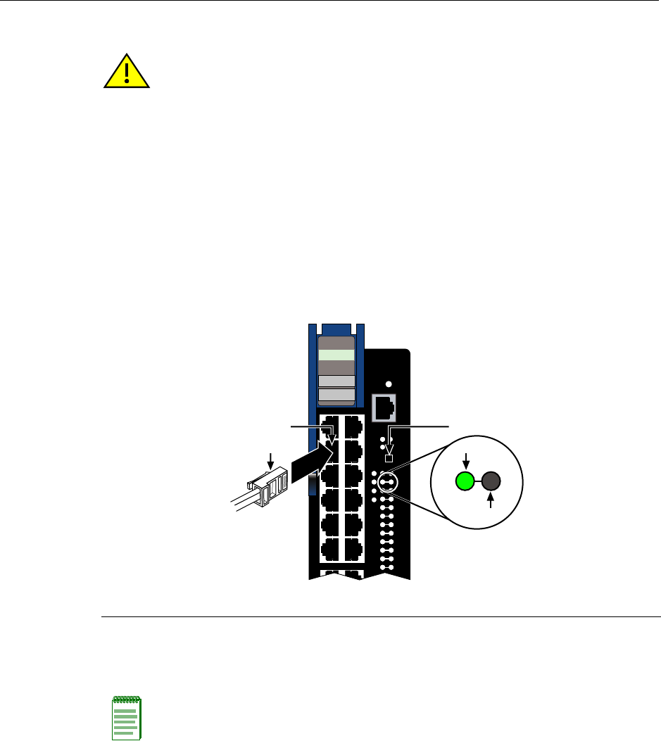
Connecting to the Network
3-16 Installation
Making the UTP Connections
ToconnectandverifyUTPcableconnectionstoRJ45ports(1through48),referto
Figure 3‐4andproceedasfollows:
1. EnsurethatthedeviceconnectedtotheotherendofthesegmentispoweredON.
2. InserttheRJ45connectoronthetwistedpairsegmentintotheappropriateRJ45port
connector.
Figure 3-4 Connecting a Twisted Pair Segment with RJ45 Connector
3. VerifythatalinkexistsbycheckingthattheportRX(Receive)LEDisON(flashing
amber,blinkinggreen,orsolidgreen).IftheRXLEDisOFFandtheTX(Transmit)
LEDisnotblinkingamber,performthefollowingstepsuntilitison:
a. Toviewthereceiveandtransmitactivityonagroupofsegments,pressthe
GROUPSELECTbuttonforlessthanonesecond(seeFigure 3‐4)tosteptothe
groupofinterest(Groups1through4).
Caution: To prevent damage to the equipment, do not connect the PoE supported ports
(1 through 48) to segments running between buildings. Keep connections to equipment
within the building.
Precaución: Para evitar que el equipo se dañe, no conecte los puertos PoE
(1 a 48) a segmentos que vayan de un edificio a otro. Mantenga las conexiones de los
equipos dentro del edificio.
1RJ45 cable connector 2RJ45 port connector 3GROUP SELECT button
Note: If the RX and TX LEDs of a port do not indicate a link and the end-point device is a
PD, you may have a port without 48 Vdc to operate the PD. To check the PoE Port Status,
refer to “Verifying PoE Port Status” on page 3-19.
1X
G
R
O
U
P
1
11X
OFFLINE/
RESET
COM
MGMT
GROUP
SELECT
GROUP
1
2
3
4
5
6
7
8
9
10
11
12
12 X
POE
CPU
1
2
3
4
7H4385-49
FAST ENET
RX
TX
À
ÁÂ
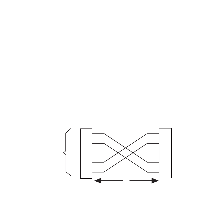
Connecting to the Network
DFE-Platinum Series Hardware Installation Guide 3-17
b. EachtimetheGROUPSELECTbuttonispressedforlessthatonesecond,the
GROUPLEDlightsupinsequence,indicatingwhichGroupisselected.The
receiveandtransmitactivityforthatgroupofsegmentsisthenindicatedbythe
RXandTXLEDsforeachsegment.
c. VerifythatthecablingbeingusedisCategory5UTPwithanimpedancebetween
85and111 ohms.Iftheportistooperateat100 Mbps,category 5cablingmustbe
used.
d. Verifythatthedeviceattheotherendofthetwistedpairsegmentison,and
properlyconnectedtothesegment.
e. VerifythattheRJ45connectorsonthetwistedpairsegmenthavetheproper
pinoutsandcheckthecableforcontinuity.Typically,acrossovercableisused
betweenhubdevices.Astraight‐throughcableisusedtoconnectbetween
switchesorhubdevicesandanenduser(computer).RefertoFigure 3‐5and
Figure 3‐6forfour‐wireRJ45connections.RefertoFigure 3‐7andFigure 3‐8for
eight‐wireRJ45connections.
Figure 3-5 Four-Wire Crossover Cable RJ45 Pinouts, Connections Between Hub
Devices
1RJ45 device port 3RJ45-to-RJ45 crossover cable
2Other device port 4RX+/RX- and TX+/TX- connections.
These connections must share a common color pair.
TX+
TX
RX+
RX 2
1
3
6
TX+
TX
2
1
3
6
RX+
RX
ÀÁ
Â
Ã
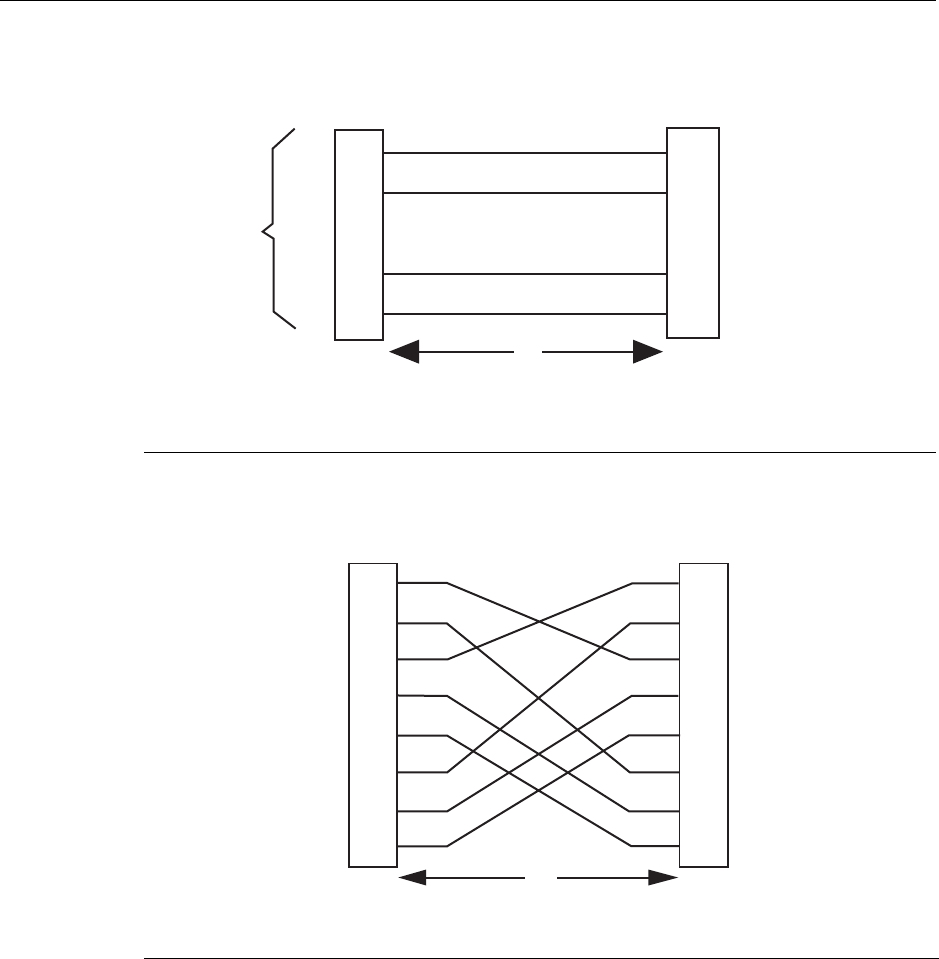
Connecting to the Network
3-18 Installation
Figure 3-6 Four-Wire Straight-Through Cable RJ45 Pinouts, Connections
Between Switches and End User Devices
Figure 3-7 Eight-Wire Crossover Cable RJ45 Pinouts, Connections Between Hub
Devices
1RJ45 device port 3RJ45-to-RJ45 straight-through cable
2Other device port 4RX+/RX- and TX+/TX- connections.
These connections must share a common color pair.
1RJ45 device port 3RJ45-to-RJ45 crossover cable
2Other device port
TX+
TX
RX+
RX 2
1
3
6
TX+
TX
2
1
3
6
RX+
RX
ÀÁ
Â
Ã
2
1
3
6
4
5
7
8
TX1+
TX2+
RX4-
RX1-
TX4+
RX3-
TX3+
RX2-
TX2+
TX1+
RX3-
RX2-
TX3+
RX4-
TX4+
RX1-
2
1
3
6
4
5
7
8
Á
À
Â
Connecting to the Network
DFE-Platinum Series Hardware Installation Guide 3-19
Figure 3-8 Eight-Wire Straight-Through Cable RJ45 Pinouts, Connections
Between Switches and End User Devices
f. EnsurethatthetwistedpairconnectionmeetsthedBlossandcablespecifications
outlinedintheCablingGuide.Referto“RelatedDocuments”inAboutThisGuide
forinformationonobtainingthisdocument.
IfalinkisnotestablishedanditisconnectedtoaPD(PoweredDevice),checkthePoE
PortStatustoensurethatthereis48Vdcpoweratthe7H4385‐49RJ45port.Referto
“VerifyingPoEPortStatus”onpage 3‐19.Ifthereisstillaproblem,contactEnterasys
Networks.Referto“GettingHelp”onpage xviiifordetails.
4. Repeatsteps1through3above,untilallconnectionshavebeenmade.
Verifying PoE Port Status
IfaPDisconnectedtothe7H4385‐49RJ45port,ensurethatthereispowerattheRJ45port
asfollows:
1. PressontheGROUPSELECTswitchformorethanonesecond.The7H4385‐49will
enterthePoEstatusmode,whichwillindicateasetofpowerstatusconditions
relatingtothePoEPortStatus.
2. Now,everytimeyoupresstheGROUPSELECTswitchforlessthanasecond,the
GROUPLEDlightsupinsequence,indicatingwhichgroupisselected.ThePoE
POWERSTATUSforthatgroupofsegmentsisthenindicatedbytheRXandTXLEDs
foreachsegment.Ifthereispowerattheport,theRXLEDisgreenandtheTXLEDis
off.Otherwise,refertoChapter 4fortroubleshootinginformation.
1RJ45 device port 3RJ45-to-RJ45 straight-through cable
2Other device port
TX1+
TX2+
RX4-
RX1-
TX4+
RX3-
TX3+
RX2-
2
1
3
6
4
5
7
8
TX2+
TX1+
RX3-
RX2-
TX3+
RX4-
TX4+
RX1-
2
1
3
6
4
5
7
8
À
Â
Á

Connecting to COM Port for Local Management
3-20 Installation
3. PressontheGROUPSELECTswitchagainformorethanonesecond.Thisreturnsthe
7H4385‐49toportRX(receive)andTX(transmit)statusmode.
Connecting to COM Port for Local Management
ThissectiondescribeshowtoinstallaUTPstraight‐throughcablewithRJ45connectors
andoptionaladapterstoconnectaPC,aVTseriesterminal,oramodemtoan
Enterasys NetworksmoduletoaccessLocalManagement.Thissectionalsoprovidesthe
pinoutassignmentsoftheadapters.
What Is Needed
Thefollowingisalistoftheuser‐suppliedpartsthatmaybeneededdependingonthe
connection:
•RJ45‐to‐DB9femaleadapter
•UTPstraight‐throughcableterminatedatbothendswithRJ45connectors
•RJ45‐to‐DB25femaleadapter
•RJ45‐to‐DB25maleadapter
UsingaUTPstraight‐throughcableandanRJ45‐to‐DB9adapter,youcanconnect
productsequippedwithanRJ45COMporttoanIBMorcompatiblePCrunningaVT
seriesemulationsoftwarepackage.
UsingaUTPstraight‐throughcableandanRJ45‐to‐DB25femaleadapter,youcanconnect
productsequippedwithanRJ45COMporttoaVTseriesterminalorVTtypeterminals
runningemulationprogramsfortheVTseries.
UsingaUTPstraight‐throughcableandanRJ45‐to‐DB25maleadapter,youcanconnect
productsequippedwithanRJ45COMporttoaHayescompatiblemodemthatsupports
9600 baud.
Connecting to an IBM PC or Compatible Device
ToconnectanIBMPCorcompatibledevice,runningtheVTterminalemulation,toan
Enterasys NetworksmoduleCOMport(Figure 3‐9),proceedasfollows:
1. ConnecttheRJ45connectoratoneendoftheUTPstraight‐throughcabletothe
communicationsCOMportontheEnterasys Networksmodule.(TheCOMportis
alsoknownasaConsoleport.)
2. PlugtheRJ45connectorattheotherendoftheUTPstraight‐throughcableintoan
RJ45‐to‐DB9adapter.
3. ConnecttheRJ45‐to‐DB9adaptertothecommunicationsportontheIBMPC.
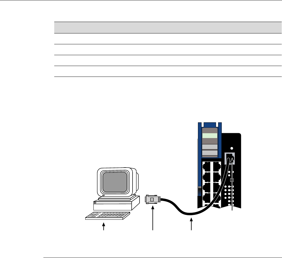
Connecting to COM Port for Local Management
DFE-Platinum Series Hardware Installation Guide 3-21
4. TurnonthePCandsetthefollowingparametersonyourVTemulationpackage:
5. Whentheseparametersareset,theLocalManagementpasswordscreenwilldisplay.
RefertotheappropriateEnterasysMatrixDFE‐PlatinumSeriesConfigurationGuidefor
furtherinformation.
Figure 3-9 Connecting an IBM PC or Compatible
Connecting to a VT Series Terminal
ToconnectaVTSeriesterminaltoanEnterasys NetworksDFE moduleCOMport
(Figure 3‐10),useaUTPstraight‐throughcablewithRJ45connectorsandanRJ45‐to‐DB25
femaleadapter,andproceedasfollows:
1. ConnecttheRJ45connectoratoneendoftheUTPstraight‐throughcabletotheCOM
portontheEnterasys Networksmodule.
Parameter Setting
Mode 7 Bit Control
Transmit Transmit=9600
Bits Parity 8 Bits, No Parity
Stop Bit 1 Stop Bit
1UTP straight-through cablewith RJ45 connectors 3RJ45-to-DB9 PC adapter
2RJ45 COM port 4IBM PC or compatible device
CPU
POE
1X
G
R
O
U
P
1
OFFLINE/
RESET
COM
MGMT
GROUP
SELECT
GROUP
1
2
3
4
5
6
1
2
3
4
7H4385-49
FAST ENET
ÂÃ À
Á
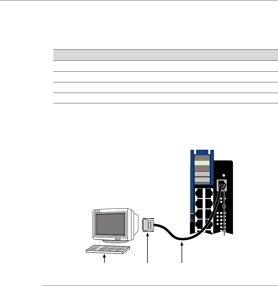
Connecting to COM Port for Local Management
3-22 Installation
2. PlugtheRJ45connectorattheotherendoftheUTPstraight‐throughcableintothe
RJ45‐to‐DB25femaleadapter.
3. ConnecttheRJ45‐to‐DB25adaptertotheportlabeledCOMMontheVTterminal.
4. TurnontheterminaltoaccesstheSetupDirectoryandsetthefollowingparameters:
Whentheseparametersareset,theLocalManagementpasswordscreenwilldisplay.
RefertotheEnterasysMatrixDFE‐PlatinumSeriesConfigurationGuideforfurther
information.
Figure 3-10 Connecting a VT Series Terminal
Connecting to a Modem
ToconnectamodemtoanEnterasys NetworksDFE moduleCOMport(Figure 3‐11),use
aUTPstraight‐throughcablewithRJ45connectorsandanRJ45‐to‐DB25maleadapter,
andproceedasfollows:
Parameter Setting
Mode 7 Bit Control
Transmit Transmit=9600
Bits Parity 8 Bits, No Parity
Stop Bit 1 Stop Bit
1UTP straight-throughcable with RJ45 connectors 3RJ45-to-DB25 VT adapter
2RJ45 COM port 4VT series terminal
 ÀÃ
CPU
POE
1X
G
R
O
U
P
1
OFFLINE/
RESET
COM
MGMT
GROUP
SELECT
GROUP
1
2
3
4
5
6
1
2
3
4
7H4385-49
FAST ENET
Á
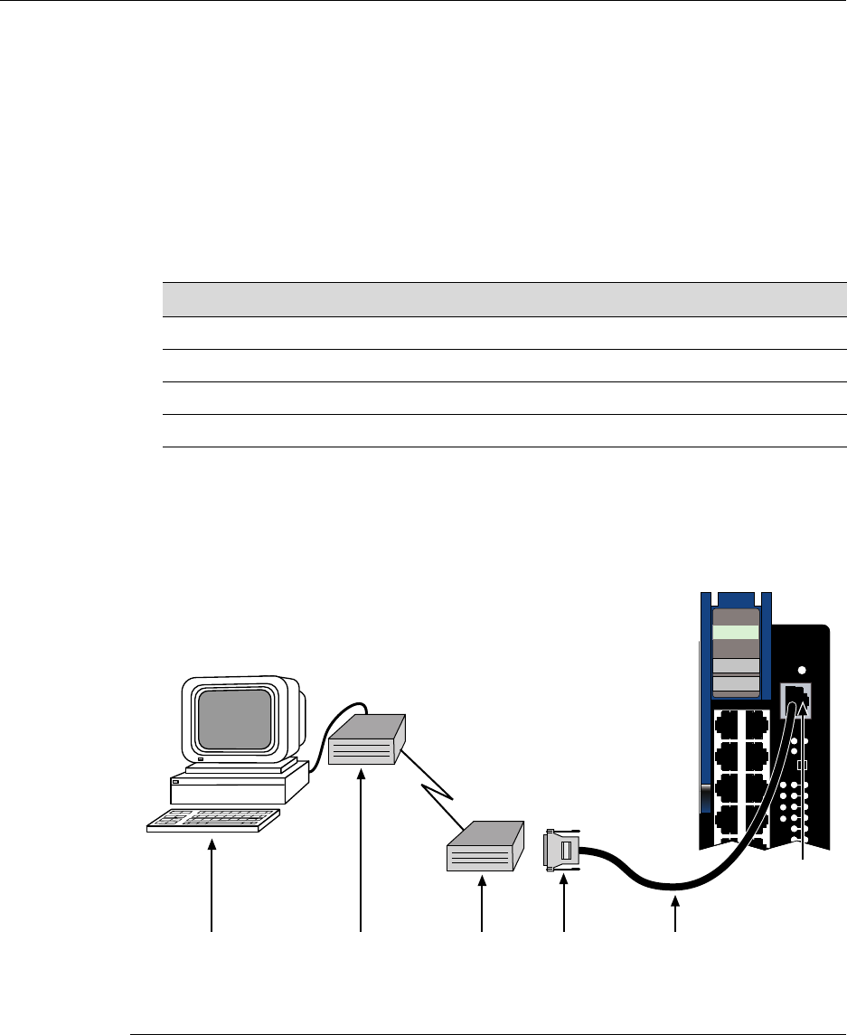
Connecting to COM Port for Local Management
DFE-Platinum Series Hardware Installation Guide 3-23
1. ConnecttheRJ45connectoratoneendoftheUTPstraight‐throughcable totheCOM
portofthemodule.
2. PlugtheRJ45connectorattheotherendoftheUTPstraight‐throughcableintothe
RJ45‐to‐DB25modemadapter.
3. ConnecttheRJ45‐to‐DB25adaptertothecommunicationsportonthemodem.
4. Turnonthemodem.
5. WithaPCconnectedtoaremotemodem,youcanconfiguretheswitchremotely.To
accomplishthis,youmustconfigureyourPCVTemulationpackagewiththe
followingparameters.
6. Whentheseparametersareset,theLocalManagementpasswordscreenwilldisplay.
RefertotheEnterasysMatrixDFE‐PlatinumSeriesConfigurationGuideforfurther
information.
Figure 3-11 Connecting to a Modem
Parameter Setting
Mode 7 Bit Control
Transmit Transmit=9600
Bits Parity 8 Bits, No Parity
Stop Bit 1 Stop Bit
1UTP straight-throughcable with RJ45 connectors 4Local modem
2RJ45 COM port 5Remote modem
3RJ45-to-DB25 modem adapter 6PC
CPU
POE
1X
G
R
O
U
P
1
OFFLINE/
RESET
COM
MGMT
GROUP
SELECT
GROUP
1
2
3
4
5
6
1
2
3
4
7H4385-49
FAST ENET
Á
ÃÄÂ ÀÅ
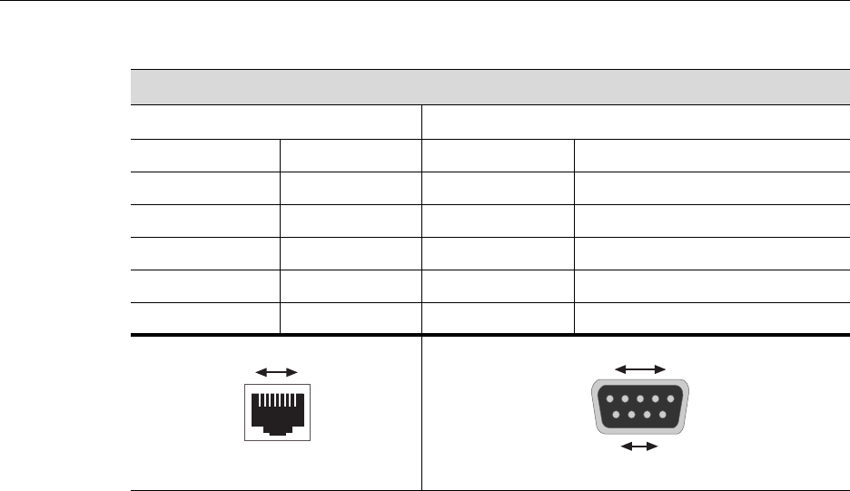
Connecting to COM Port for Local Management
3-24 Installation
Adapter Wiring and Signal Assignments
COM Port Adapter Wiring and Signal Diagram
RJ45 DB9
Pin Conductor Pin Signal
1 Blue 2 Receive (RX)
4 Red 3 Transmit (TX)
5 Green 5 Ground (GRD)
2 Orange 7 Request to Send (RTS)
6 Yellow 8 Clear to Send (CTS)
RJ45 Connector (Female)
81
Pins
DB9 Connector (Female)
Pins
15
69
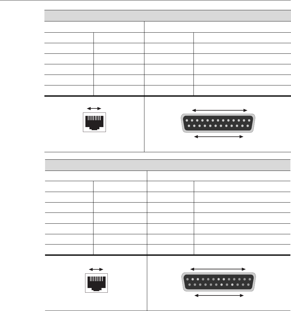
Connecting to COM Port for Local Management
DFE-Platinum Series Hardware Installation Guide 3-25
VT Series Port Adapter Wiring and Signal Diagram
RJ45 DB25
Pin Conductor Pin Signal
4 Red 2 Transmit (TX)
1 Blue 3 Receive (RX)
6 Yellow 5 Clear to Send (CTS)
5 Green 7 Ground (GRD)
2 Orange 20 Data Terminal Ready
Modem Port Adapter Wiring and Signal Diagram
RJ45 DB25
Pin Conductor Pin Signal
1 Blue 2 Transmit (TX)
2 Orange 8 Data Carrier Detect (DCD)
4 Red 3 Receive
5 Green 7 Ground (GRD)
6 Yellow 20 Data Terminal Ready (DTR)
8 Gray 22 Ring Indicator
RJ45 Connector (Female)
81
Pins
DB25 Connector (Female)
Pins
113
1425
RJ45 Connector (Female)
Pins 81
045905
RJ45 Connector (Female)
81
Pins
DB25 Connector (Male)
131
Pins
14 25

Completing the Installation
3-26 Installation
Completing the Installation
CompletingtheDFEmoduleinstallationdependsonifthemoduleisbeinginstalledin:
•anewDFEmodulesystem(referto“CompletingtheInstallationofaNewSystem”on
page 3‐26),or
•anestablished,operatingDFEmodulesystem(referto“CompletingtheInstallationof
aDFEModuleinanExistingSystem”onpage 3‐28).
Completing the Installation of a New System
InanewsystemofDFEmodules,oneoftheinstalledDFEmoduleswillbecomethe
managementmoduleonchassispowerup,andallDFEmoduleswillautomaticallybeset
tothefactorydefaultvalues.Acompletelistofthefactorydefaultvaluesareprovidedin
Chapter3oftheEnterasysMatrixDFE‐PlatinumSeriesConfigurationGuide.
AfterinstallingallDFE modulesintothehostchassisandmakingtheconnectionstothe
network,proceedtothefollowingFirst‐TimeLog‐InUsingaConsolePortConnection
proceduretoaccessthemodulemanagementstartupscreenfromyourPC,terminal,or
modemconnection.
First-Time Log-In Using a Console Port Connection
StarttheCommandLineInterface(CLI)fromthemodule’slocalconsoleportasfollows:
1. Connectaterminaltothelocalconsoleportasdescribedin“ConnectingtoCOMPort
forLocalManagement”onpage 3‐20.Thestartupscreen,Figure 3‐12,displays.
2. Attheloginprompt,enteroneofthefollowingdefaultusernames:
–roforRead‐Onlyaccess,
–rwforRead‐Writeaccess,or
–adminforSuperUseraccess.(ThisaccesslevelallowsRead‐Writeaccesstoall
modifiableparameters,includinguseraccounts.)
3. PressENTER.
4. ThePasswordpromptdisplays.LeavethisstringblankandpressENTER.The
moduleinformationandMatrixpromptdisplaysasshowninFigure 3‐12.
Notes: This procedure applies only to initial log-in, and to logging in to a device not yet
configured with administratively-supplied user and password settings.
By default, the Matrix DFE Series device is configured with three user login accounts: ro
for Read-Only access; rw for Read-Write access; and admin for super-user access to all
modifiable parameters. The default password is set to blank (press ENTER). For
information on changing these default passwords, refer to Chapter 3 in the Enterasys
Matrix DFE-Platinum Series Configuration Guide.

Completing the Installation
DFE-Platinum Series Hardware Installation Guide 3-27
TheDFE moduleisnowreadytobeconfigured.ForinformationaboutsettingtheIP
addressandconfiguringTelnetsettingsforremoteaccesstoDFEmanagement,referto
Chapter3intheEnterasysMatrixDFE‐PlatinumSeriesConfigurationGuide.TheCLI
commandsenableyoutoinitiallysetupandperformmoreinvolvedmanagement
configurations.
TheEnterasysMatrixDFE‐PlatinumSeriesConfigurationGuideisavailableonlineat:
http://www.enterasys.com/support/manuals
Ifyourequireassistance,contactEnterasysNetworksusingoneofthemethodsdescribed
in“GettingHelp”onpage xviii.
Figure 3-12 Matrix DFE Startup Screen Example (N7 Chassis)
login: admin
Password:
M A T R I X N7
Command Line Interface
Enterasys Networks, Inc.
50 Minuteman Rd.
Andover, MA 01810-1008 U.S.A.
Phone: +1 978 684 1000
E-mail: support@enterasys.com
WWW: http://www.enterasys.com
(c) Copyright Enterasys Networks, Inc. 2003
Chassis Serial Number: xxxxxxxxxxxx
Chassis Firmware Revision: xx.xx.xx
Matrix N7(su)->

Completing the Installation
3-28 Installation
Completing the Installation of a DFE Module in an Existing System
InanestablishedDFEmodulesystem,
•aDFEmoduleisalreadyestablishedasthemanagementmodule,
•thepasswordshavealreadybeensetforvarioususers,
•thesystemIPaddressisset,and
•othersystemparametershavebeenset.
WhenyouinstallanewDFEmoduleintoasystemwithanexistingconfigureduser
account,thecurrentsystemsettingsinthataccountarealreadyrecognizedbythenew
DFEmoduleanditwilloperateaccordingly.
Ifyouneedtochangeanysettings,youcanconnectaterminaltothelocalconsoleportas
describedin“ConnectingtoCOMPortforLocalManagement”onpage 3‐20toaccess
systemmanagement,oruseaTelnetconnectiontoaccesstheDFEmodulesystem
managementasdescribedinChapter3oftheEnterasysMatrixDFE‐PlatinumSeries
ConfigurationGuide.
Logging in with an Administratively-Configured User Account
Ifthedevice’sdefaultuseraccountsettingshavebeenchanged,proceedasfollows:
1. Attheloginprompt,enteryouradministratively‐assignedusernameandpress
ENTER.
2. AtthePasswordprompt,enteryourpasswordandpressENTER.
ThenoticeofauthorizationandtheMatrixpromptdisplaysasshownbackinFigure 3‐12.
TheDFE moduleisnowreadytobeconfigured.ForinformationaboutsettingtheIP
addressandconfiguringTelnetsettingsforremoteaccesstoDFEmanagement,referto
Chapter3intheEnterasysMatrixDFE‐PlatinumSeriesConfigurationGuide.TheCLI
commandsenableyoutoinitiallysetupandperformmoreinvolvedmanagement
configurations.
TheEnterasysMatrixDFE‐PlatinumSeriesConfigurationGuideisavailableonlineat:
http://www.enterasys.com/support/manuals
Ifyourequireassistance,contactEnterasysNetworksusingoneofthemethodsdescribed
in“GettingHelp”onpage xviii.
Note: Users with Read-Write (rw) and Read-Only access can use the set password
command to change their own passwords. Administrators with Super User (su) access
can use the set system login command to create and change user accounts, and the set
password command to change any local account password. For information on the set
password and set system login commands, refer to Chapter 3 in the Enterasys Matrix
DFE-Platinum Series Configuration Guide.

DFE-Platinum Series Hardware Installation Guide 4-1
4
Troubleshooting
Thischapterprovidesinformationconcerningthefollowing:
Using LANVIEW
TheDFEmoduleusesabuilt‐invisualdiagnosticandstatusmonitoringsystemcalled
LANVIEW.TheLANVIEWLEDs(Figure 4‐1)allowquickobservationofthenetwork
statustoaidindiagnosingnetworkproblems.
About the Management (MGMT) LED
TheMGMTLED(showninFigure 4‐1)indicateswhenthemoduleisservingasthe
ManagementModuletocontrolthemanagementfunctionsforallDFEmodulesinthe
chassis.TheManagementModulehandlesallIPrequeststothechassisIPaddress,such
as,butnotlimitedto,PING,Telnet,SNMP,HTTP.TheManagementModulealsohandles
theCLIconfigurationsessionsthroughtheconsoleport.So,whenyouplugintoaDFE
moduleCOMporttoconfigureaDFEmoduleinthechassis,itishandledbythe
ManagementModuleregardlessoftheDFEmoduleCOMportthatyouuse.
For information about... Refer to page...
Using LANVIEW 4-1
Troubleshooting Checklist 4-6
Overview of DFE Module Shutdown Procedure 4-8
Recommended Shutdown Procedure Using OFFLINE/RESET Switch 4-9
Last Resort Shutdown Procedure Using OFFLINE/RESET Switch 4-10
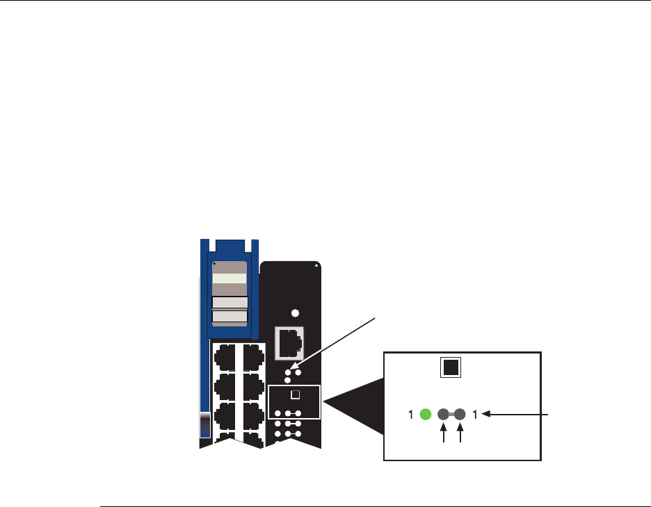
Using LANVIEW
4-2 Troubleshooting
Viewing the Receive and Transmit Activity
Youcanviewthe7H4385‐49receiveandtransmitportactivityontheRXandTXLEDs.
However,onlyonegroupof12portsmaybeviewedatatime.
Toviewthereceiveandtransmitactivityonagroupof7H4385‐49segments,pressthe
GROUPSELECTbutton(seeFigure 4‐1)forlessthanonesecondtosteptothegroupof
interest(Groups1through4).EachtimetheGROUPSELECTbuttonispressedforless
thanonesecond,theGROUPLEDlightsupinsequence,indicatingwhichgroupis
selected.Thereceiveandtransmitactivityforthatgroupofsegmentsisthenindicatedby
theRXandTXLEDsforeachport.
Figure 4-1 LANVIEW LEDs
Viewing the PoE Port Status
Ifthe7H4385‐49isinstalledinanN5chassisorisreceiving48Vdcfromanexternal
N‐POEPowerSystemtosupportconnectionstoPDs(PoweredDevices),youcanviewthe
powerstatusindicationsontheRXandTXLEDs.However,onlyonegroupof12ports
maybeviewedatatime.ToviewthePoEportstatus,refertoFigure 4‐1andproceedas
follows:
1. PresstheGROUPSELECTbuttonformorethanonesecond.The7H4385‐49willenter
thePoEportstatusmode.
2. Now,everytimeyoupresstheGROUPSELECTbuttonforlessthanasecond,the
GROUPLEDlightsupinsequence,indicatingwhichGroupisselected.ThePoE
POWERSTATUSforthatgroupofsegmentsisthenindicatedbytheRXandTXLEDs
foreachsegment.Ifthereispowerattheport,theRXLEDisgreenandtheTXLEDis
off.Otherwise,refertoTable 4‐1fortroubleshootinginformation.
1MGMT LED 2Group 1, Port 1 LEDs
1X
G
R
O
U
P
1
RESET
COM
CPU
MGMT
GROUP
SELECT
GROUP
1
2
3
1
2
3
4
7H4385-49
FAST ENET
GROUP
GROUP
SELECT
RX TX
À
Á
POE
Using LANVIEW
DFE-Platinum Series Hardware Installation Guide 4-3
3. PresstheGROUPSELECTbuttonagainformorethanonesecond.Thisreturnsthe
7H4385‐49tothedefaultstatusmodetomonitorRX(receive)andTX(transmit)
activity.
Table 4‐1describestheLEDindicationsandprovidesrecommendedactionsas
appropriate.
Note: The terms used in Tab l e 4 -1 indicate the following:
•Flashing indicates LED is flashing randomly.
•Blinking indicates LED is flashing at a steady rate (approximately 50% on, 50% off).
•Solid indicates a steady LED light. No pulsing.
•Alternating indicates LED is flashing in a steady rate other than 50% on, 50% off.
Table 4-1 LANVIEW LEDs
LED Color State Recommended Action
MGMT Off Off. This DFE module is NOT
the Management Module.
None.
Green Solid. This module is the
designated Management
Module.
None.
Amber Flashing. This is a
temporary indication that the
DFE module is saving data.
None.
CPU Off Power off. Ensure chassis has adequate power.
Amber Blinking. DFE module in
process of booting.
None.
Solid. Testing. If the LED remains amber for several
minutes, contact Enterasys Networks
for technical support.
Green Blinking. Image starts
running.
None.
Solid. Functional. None.
Red Solid. Processor in reset. None.
Green and
Amber
Blinking. Indicates that the
DFE module is in the process
of shutting down.
None. This state is activated when the
OFFLINE/RESET switch is pressed for
less than 1 second to start the process
of an orderly shutdown.
While in this state, do not remove any
DFE module.

Using LANVIEW
4-4 Troubleshooting
CPU
(cont’d)
Amber and
off
Alternating (67% on, 33%
off). Indicates that a
shutdown process has
completed. This indication
will remain for 60 seconds
before automatically
restarting.
While in this state, you have 60 seconds
to safely remove the DFE module from
the chassis.
RX/TX Indications in Standard Mode
RX
(Receive)
Off No link. No activity. Port
enabled or disabled.
None.
Green Solid. Link present, port
enabled, no traffic is being
received by the interface.
None.
Amber Flashing. Link present, port
enabled, traffic is being
received by the interface.
None.
Red Blinking. Indicates
collisions. This indication is
only supported on 10/100
ports.
Contact Enterasys Networks for
technical support.
TX
(Transmit)
Off Port enabled, but no activity. If it is known that the port should be
active and is not, contact
Enterasys Networks for technical
support.
Green Flashing. Indicates data
transmission activity. Rate of
flashing indicates the data
rate.
None.
Red Flashing. Fault or Error
(collision).
None, unless there is a high rate of
activity. In this case, check for network
configuration problems or a defective
device.
Table 4-1 LANVIEW LEDs (continued)
LED Color State Recommended Action

Using LANVIEW
DFE-Platinum Series Hardware Installation Guide 4-5
RX/TX LED Indications in PoE Port Status Mode
RX/TX Green/Off There is a connection to a
PD. There is 48 Vdc at the
RJ45 connector.
None.
Off/Red Port is off due to overload.
The attached device
exceeded maximum load
according to 802.3af
standard PoE device power
classification.
1. Check the attached PD to see if it is
defective and drawing too much
power for its Power Classification.
2. Check Ethernet cable from the PD
for short circuits.
3. Contact Enterasys Networks for
technical support.
Red/Off Port is off due to PoE power
management. Port may be
turned off due to priority or
other administration
configuration.
None
Off/Off Port is off for other reason. 1. There is no connection to a PD.
2. If the DFE module is in an N5
chassis, ensure that the N5 is turned
on.
3. If connected to an N-POE Power
System, ensure that it is turned on.
4. If the power is being received from
an N-POE Power System, check the
48 Vdc power cable connection.
5. Swap 48 Vdc power cable with a
known good one.
6. If you still have a problem, contact
Enterasys Networks for technical
support.
Table 4-1 LANVIEW LEDs (continued)
LED Color State Recommended Action

Troubleshooting Checklist
4-6 Troubleshooting
Troubleshooting Checklist
Ifthemoduleisnotworkingproperly,refertoTable 4‐2onpage 4‐6forachecklistof
problems,possiblecauses,andrecommendedactionstoresolvetheproblem.
Table 4-2 Troubleshooting Checklist
Problem Possible Cause Recommended Action
All LEDs are OFF. Loss of power. Ensure that the DFE module was installed
properly according to the installation
instructions in Chapter 3, and that the
host chassis is providing power.
No Local
Management
Password screen.
Incorrect terminal setup. Refer to the Enterasys Matrix
DFE-Platinum Series Configuration Guide
for proper setup procedures.
Improper console cable
pinouts.
Refer to Appendix A for proper COM port
pinouts.
Corrupt firmware image, or
hardware fault.
If possible, attempt to download the
image to the DFE module again. Refer to
“Setting the Mode Switches” on page B-2
for instructions to clear NVRAM.
Cannot navigate
beyond Password
screen.
Improper username/ password
combination entered.
If the username/password combination
has been forgotten, refer to “Setting the
Mode Switches” on page B-2 for
instructions on how to set the mode
switch to reset the username/password
combination to the default values.

Troubleshooting Checklist
DFE-Platinum Series Hardware Installation Guide 4-7
Cannot contact the
module through in-
band management.
IP address not assigned. Refer to the Enterasys Matrix
DFE-Platinum Series Configuration Guide
for the IP address assignment procedure.
Port is disabled. Enable port. Refer to the Enterasys Matrix
DFE-Platinum Series Configuration Guide
for instructions to enable/disable ports.
Host Port policy and/or
management VLAN is
incorrectly configured, or not
configured.
Verify that a management VLAN exists
and that it is associated with the Host
Port.
Refer to the Enterasys Matrix
DFE-Platinum Series Configuration Guide
for information about Host Port and
management VLAN configuration.
No link to device. Verify that all network connections
between the network management station
and the DFE module are valid and
operating.
If the problem continues, contact
Enterasys Networks for technical support.
Port(s) goes into
standby for no
apparent reason.
Loop condition detected. Verify that Spanning Tree is enabled.
Refer to the Enterasys Matrix
DFE-Platinum Series Configuration Guide
for the instructions to set the type of STA.
Review the network design and delete
unnecessary loops.
If the problem continues, contact
Enterasys Networks for technical support.
Table 4-2 Troubleshooting Checklist (continued)
Problem Possible Cause Recommended Action
Overview of DFE Module Shutdown Procedure
4-8 Troubleshooting
Overview of DFE Module Shutdown Procedure
TheDFEmodulesinstalledinaMatrix E7,MatrixN3,MatrixN5,orMatrixN7chassisare
interdependentandoperateunderasingleIPaddressasasingle,distributedswitch
system(hardware,databases,andpersistentstorage).Inthisoperatingenvironment,the
DFEmodulemustshutdowninanorderlyfashiontoensurethattheothermodulesinthe
systemandotherdevicesonthenetworkarenotifiedoftheimpendingchange.The
device(s)canthenmakeintelligentdecisionsandstabilizethenetworkbeforethechange
ismade,therebyincreasingnetworkavailability.
YoucanshutdownaDFEmoduleinanoperatingsystemusingtheOFFLINE/RESET
switchshowninFigure 4‐2.TherearetwoprocedurestoshutdownaDFEmodule.
• Recommendedshutdownprocedure(“RecommendedShutdownProcedureUsing
OFFLINE/RESETSwitch”onpage 4‐9)
• Lastresortshutdownprocedure (notrecommended) (“LastResortShutdown
ProcedureUsingOFFLINE/RESETSwitch”onpage 4‐10)
User parameters (IP
address, device and
module name, etc.)
were lost when the
module power was
cycled, the front
panel OFFLINE/
RESET switch was
pressed.
Position of Mode switch (7),
Persistent Data Reset, was
changed sometime before
either cycling power or
pressing the OFFLINE/RESET
switch, causing the user-
entered parameters to reset to
factory default settings.
Clear Persistent Data that was
set through Local
Management.
The DFE module was moved
either from slot-to-slot or from
chassis-to-chassis.
Reenter the lost parameters as
necessary. Refer to the Enterasys Matrix
DFE-Platinum Series Configuration Guide
for the instructions to configure the
DFE module.
If the problem continues, contact
Enterasys Networks for technical support.
Table 4-2 Troubleshooting Checklist (continued)
Problem Possible Cause Recommended Action
Caution: Do not remove a DFE module from an operating chassis system before reading
the following information and instructions.
Precaución: Antes de retirar los módulos DFE del chasis en funcionamiento, lea las
siguientes instrucciones y la información suministrada.
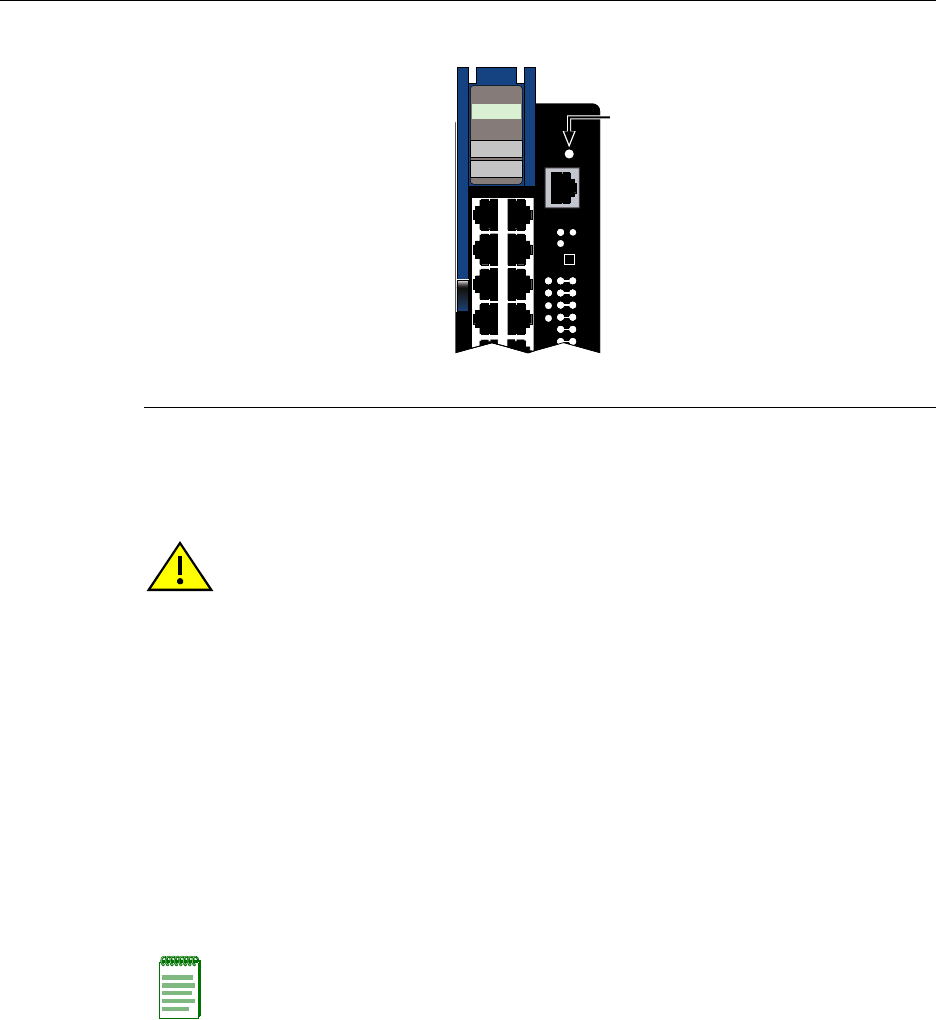
Overview of DFE Module Shutdown Procedure
DFE-Platinum Series Hardware Installation Guide 4-9
Figure 4-2 OFFLINE/RESET Switch
Recommended Shutdown Procedure Using OFFLINE/RESET
Switch
BeforepullingaDFEmoduleoutofachassis,
pressortaponitsOFFLINE/RESETswitchforlessthan1 second.
ItsCPULEDchangesfromsolidgreentoblinkingbetweengreenandamber,indicating
thattheDFEmoduleisshuttingdown.AttheendoftheDFEmoduleshutdownroutine,
theCPULEDchangestoa67%/33%sequenceofamber/off,respectively,indicatingthe
moduleisinahaltstate.InthistimeitissafetorestartorremovetheDFEmodulefrom
thechassis.
WhenacontrolledshutdownisinitiatedfromtheOFFLINE/RESETswitch,youhave60
secondsfromthetimetheCPUstartsflashingamber/offuntilthetimethedeviceis
automaticallyrestarted.
1OFFLINE/RESET switch (in similar location on all DFE modules)
À
CPU
POE
1X
G
R
O
U
P
1
OFFLINE/
RESET
COM
MGMT
GROUP
SELECT
GROUP
1
2
3
4
5
6
1
2
3
4
7H4385-49
FAST ENET
Caution: Do not pull any DFE module out of an operating chassis before it has completed
its shutdown routine.
Precaución: No retire los módulos DFE del chasis en funcionamiento hasta que no se
haya terminado con la rutina de apagado.
Note: The only safe time to pull a DFE module out of the chassis is when the CPU LED is
blinking amber. Otherwise, system operation will be interrupted.

Overview of DFE Module Shutdown Procedure
4-10 Troubleshooting
Last Resort Shutdown Procedure Using OFFLINE/RESET Switch
ToresetaDFEmodulewithoutitperforminganorderlyshutdownroutine,
pressandholdthe OFFLINE/RESETswitchforapproximately6seconds.
PullinganyDFEmoduleoutofthechassisbeforeithasbeenshutdownisnot
recommended.Theonlysafetimetopullamoduleoutofthechassisisafterthe
completionofashutdownandthemanagementLEDisflashingamber/off.
Caution: This method of shutting down a DFE module is not recommended except as a
last resort, because all processes currently running on the module will be interrupted
resulting in loss of frames.
Precaución: No se recomienda utilizar este método para apagar los módulos DFE- Gold.
Recurra a él sólo como último recurso, puesto que interrumpe todos los procesos del
módulo en funcionamiento, lo que podría resultar pérdidas de frames.

‡FE-Platinum Series Hardware Installation Guide A-1
A
Specifications
Thisappendixprovidesinformationaboutthefollowing:
EnterasysNetworksreservestherighttochangethespecificationsatanytimewithout
notice.
DFE Module Specifications
Table A‐1providestheInput/Outputports,processorsandmemory,physical,and
environmentalmodulespecificationsforthe7H4385‐49DFEmodule.
For information about... Refer to page...
DFE Module Specifications A-1
COM Port Pinout Assignments A-2
Regulatory Compliance A-3
Table A-1 7H4385-49Specifications
Item Specification
Ports 1 through 48 Forty-eight, 10BASE-T/100BASE-TX ports by way of RJ45
connectors. These ports also support PoE operation.
Option Slot Supports one optional NEM.
Optional Power Input 48 Vdc, 20 A Maximum power input connection from an
Enterasys Matrix N-POE Power System.
Processors/Memory
Processor MPC750CX, 400 MHz processor
Dynamic Random Access Memory
(DRAM)
256 MB
FLASH Memory 32 MB

COM Port Pinout Assignments
A-2 Specifications
COM Port Pinout Assignments
TheCOMportisaserialcommunicationsportforlocalaccesstoLocalManagement.
RefertoTable A‐2fortheCOMportpinassignments.
Physical
Dimensions 46.43 H x 6.05 W x 29.51 D (cm)
18.28 H x 2.38 W x 11.62 D (in.)
Approximate Weight Gross: 5.54 kg (12.0 lb) (shipping carton containing
one module)
Net: 4.10 kg (9.0 lb) (one module without packaging)
Predicted hours for Mean Time
Between Failures (MTBF)
For the MTBF hours for this product, refer to the MTBF web
site at URL: http://www.enterasys.com/support/mtbf/
Environmental
Operating Temperature 5°C to 40°C (41°F to 104°F)
Storage Temperature -30°C to 73°C (-22°F to 164°F)
Operating Relative Humidity 5% to 90% (non-condensing)
Table A-1 7H4385-49Specifications (continued)
Item Specification
Table A-2 COM Port Pin Assignments
Pin Signal Name Input/Output
1 Transmit Data (XMT) Output
2 Clear to Send (CTS) Input
3 Data Set Ready (DSR) Input
4 Receive Data (RCV) Input
5 Signal Ground (GND) NA
6 Request to Send (RTS) Output
7 Data Terminal Ready (DTR) Output
8 Data Carrier Detect (DCD) Input

Regulatory Compliance
‡FE-Platinum Series Hardware Installation Guide A-3
Regulatory Compliance
The7H4385‐49meetsthesafetyandelectromagneticcompatibility(EMC)requirements
listedinTable A‐3:
Table A-3 Compliance Standards
Regulatory Compliance Standards
Safety UL 60950, CSA C22.2 No. 60950, 73/23/EEC,
EN 60950, IEC 60950, EN 60825, 21 CFR 1040.10
Electromagnetic Compatibility (EMC) 47 CFR Parts 2 and 15, CSA C108.8, 89/336/EEC,
EN 55022, EN 61000-3-2, EN 61000-3-3, EN 55024,
AS/NZS CISPR 22, VCCI V-3

Regulatory Compliance
A-4 Specifications
DFE-Platinum Series Hardware Installation Guide B-1
B
Mode Switch Settings and Option Installations
Thisappendixcoversthefollowingitems:
Required Tools
Usethefollowingtoolstoperformtheproceduresprovidedinthisappendix:
•Antistaticwriststrap
• Phillipsscrewdriver
For information about... Refer to page...
Required Tools B-1
Setting the Mode Switches B-2
Memory Locations and Replacement Procedures B-3
Gaining Access to Memory Modules B-4
Caution: An antistatic wrist strap is required to perform the procedures in this appendix.
Use the antistatic wrist strap shipped with chassis when performing any of the procedures
in this appendix to minimize ESD damage to the devices involved.
Precaución: Para llevar a cabo los procedimientos especificados en el apéndice deberá
utilizar una pulsera antiestática. Para realizar cualquiera de los procedimientos
especificados en el apéndice, no olvide utilizar la pulsera electrostática que acompaña el
chasis para minimizar los efectos de las descargas de electricidad estática.

Setting the Mode Switches
B-2 Mode Switch Settings and Option Installations
Setting the Mode Switches
Figure B‐1showsthelocationofthemodeswitchesandtheswitchsettingsfornormal
operation.Theseswitchesaresetatthefactoryandrarelyneedtobechanged.
Switchdefinitionsandpositionsareasfollows:
•Switches1through6–ForEnterasys Networksuseonly.
•Switch7–ClearPersistentData.ChangingthepositionofthisswitchclearsPersistent
Dataonthenextpower‐upofthemodule.Alluser‐enteredparameters,suchastheIP
address,modulenames,etc.,areresettothefactorydefaultsettings.Oncethemodule
resets,youcaneitherusethefactorydefaultsettingsorreenteryourownparameters.
•Switch8–ClearAdminPassword.Changingthepositionofthisswitchclearsthe
adminpassword,andrestoresthefactorydefaultpasswordonthenextpower‐upof
themodule.Oncethemoduleresets,youcaneitherusethefactorydefaultsettingsor
reenteryourownpassword.
Caution: Read the appropriate sections to be fully aware of the consequences when
changing switch settings.
Only qualified personnel should change switch settings.
Precaución: Si desea modificar la configuración del interruptor, lea las secciones
correspondientes para saber cuál será el resultado de hacerlo.
Estas modificaciones a la configuración sólo debe realizarlas personal calificado.
Note: Do not change the position of Switch 8 unless it is necessary to reset the admin
password to its factory default setting.
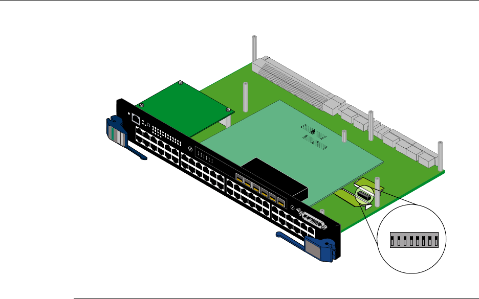
Memory Locations and Replacement Procedures
DFE-Platinum Series Hardware Installation Guide B-3
Figure B-1 Mode Switch Location (7H4385-49 shown without safety cover)
Memory Locations and Replacement Procedures
IftheDualIn‐lineMemoryModule(DIMM)orDRAMSingleIn‐lineMemoryModule
(SIMM)(FLASHmemory)needstobereplaced,thefollowingsectionsdescribehowto
access,locate,andreplacethesememorymodules.Ifyouhavequestionsconcerningthe
replacementofeithermemorymodule,referto“GettingHelp”onpage xviiifordetails
onhowtocontactEnterasys Networks.
Figure B‐2showstheDIMMandDRAMSIMMlocationsonthemainPCboard.
1Mode switch pack (7H4385-49 shown without safety cover)
1
2
3
4
5
6
1
2
3
4
5
6
7G-6MGBIC-A
1X
G
R
O
U
P
1
G
R
O
U
P
2
11X
13X
23X
OFFLINE/
RESET
COM
CPU
MGMT
GROUP
SELECT
GROUP
1
2
3
4
5
6
7
8
9
10
11
12
POE
12 X
14X
24X
G
R
O
U
P
3
25X
35X
26X
36X
G
R
O
U
P
4
37X
47X
38X
48X
1
2
3
4
48V --- 20A MAX
OPTIONAL
POWER INPUT
G
R
O
U
P
1
1X
7H4385-49
FAST ENET
DFE
1 2345678
ON
À
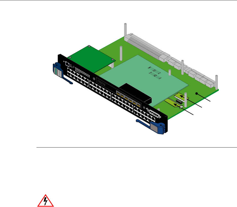
Gaining Access to Memory Modules
B-4 Mode Switch Settings and Option Installations
Figure B-2 DIMM and DRAM SIMM Locations (7H4385-49 shown without safety
cover)
Gaining Access to Memory Modules
BeforeyoucanreplacetheDRAMSIMM,youmustgainaccesstoitbyremovingthe
safetycoverandthenetworkexpansionmodule,ifoneisinstalled.Togainaccesstothe
DIMM,youonlyneedtoremovethesafetycover.
1DRAM SIMM 2DIMM 3Main PC board
1
2
3
4
5
6
1
2
3
4
5
6
7G-6MGBIC-A
1X
G
R
O
U
P
1
G
R
O
U
P
2
11X
13X
23X
OFFLINE/
RESET
COM
CPU
MGMT
GROUP
SELECT
GROUP
1
2
3
4
5
6
7
8
9
10
11
12
POE
12 X
14X
24X
G
R
O
U
P
3
25X
35X
26X
36X
G
R
O
U
P
4
37X
47X
38X
48X
1
2
3
4
48V --- 20A MAX
OPTIONAL
POWER INPUT
G
R
O
U
P
1
1X
7H4385-49
FAST ENET
DFE
À
Á
Â
Electrical Hazard: To prevent exposure to an energy hazard in a 7H4385-49 connected
to an external N-POE Power System, disconnect the 48-Vdc power cable from the 48-Vdc
input connector before servicing or removing the 7H4385-49.
Riesgo Eléctrico: Para prevenir la exposicion a un riesgo electrico en una tarjeta
7H4385-49 conectada a un sistema externo de energia N-POE Power System,
desconectar el cable de poder de 48-Vdc del conector de entrada 48-Vdc antes de dar
servicio o remover la tarjeta 7H4385-49.
Elektrischer Gefahrenhinweis: Um den Schutz vor el. Schäden des Moduls
(7H4385-49) zu gewähleisten, bei Verwendung der N-POE Systeme, sollte dies bevor
man dieses entnimmt oder Servicearbeiten daran vornimmt, vom 48-Vdc Stecker getrennt
werden.

Gaining Access to Memory Modules
DFE-Platinum Series Hardware Installation Guide B-5
Removing the Safety Cover
RefertoFigure B‐3andproceedasfollows:
1. Attachtheantistaticwriststrap(refertotheinstructionsontheantistaticwriststrap
package).
2. PlacetheDFEmoduleonanantistaticpadonasturdyflatsurface.
3. Removethesevenscrewsfasteningthesafetycovertothesevenstandoffsonthemain
board.Saveallscrewsforlaterusetoreinstallthesafetycover.
4. IfyouneedtoreplacetheDIMM,proceedto“DIMMReplacementProcedure”on
page B‐10.IfyouarereplacingtheDRAMSIMM,proceedto“DRAMSIMM
ReplacementProcedure”onpage B‐7.
Warning: The safety cover protects you from exposure to an energy hazard in excess of
240 Volt-Amperes. Never operate the DFE module without the safety cover installed.
Advertencia: La cubierta de seguridad lo protege de exponerlo al riesgo de energía en
exceso de 240 Volt -Amperes.Nunca se debe opererar el modulo de DFE sin la cobertura
de seguridad instalada.
Warnhinweis: Die Sicherheitsabdeckung schützt vor Stromstössen von bis zu 240 VA.
Bitte nehmen Sie niemals die DFE Module ohne die Abdeckung in Betrieb.
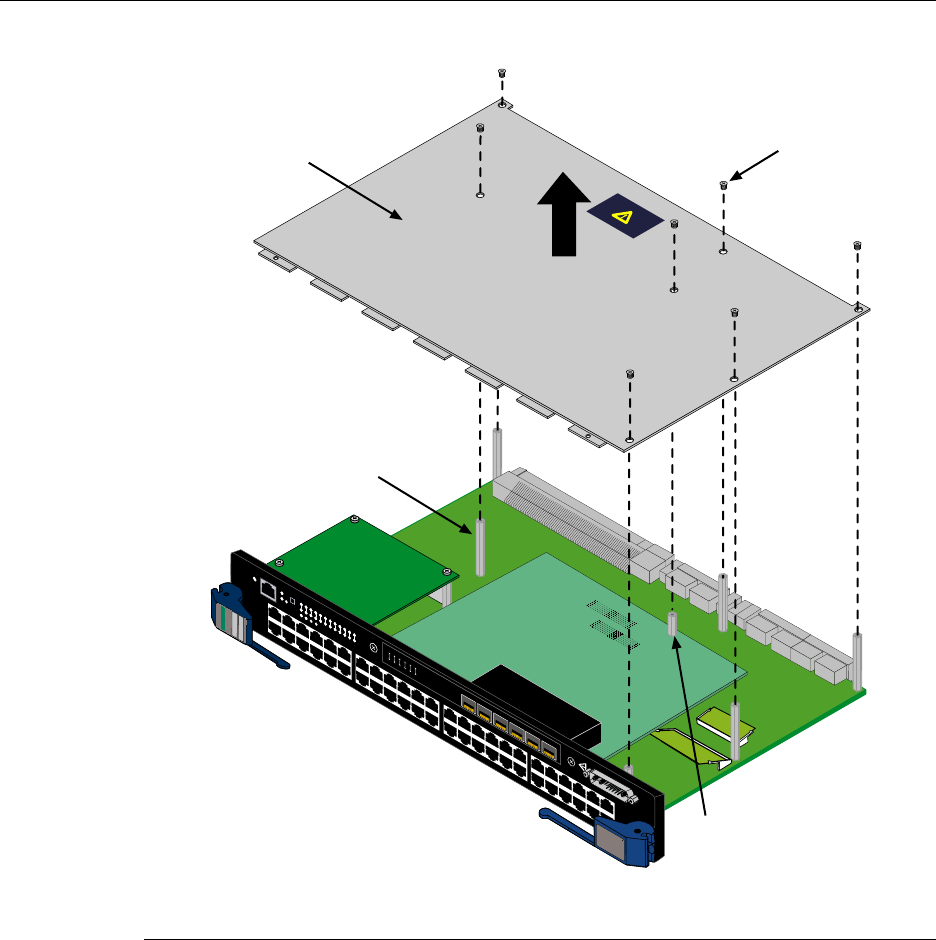
Gaining Access to Memory Modules
B-6 Mode Switch Settings and Option Installations
Figure B-3 Removing the Safety Cover
1Safety cover 3Standoffs (7)
2Cover screws (7) 4Standoff/spacer screwed to standoff under the NEM
1
2
3
4
5
6
1
2
3
4
5
6
7G-6MGBIC-A
1X
G
R
O
U
P
1
G
R
O
U
P
2
11X
13X
23X
OFFLINE/
RESET
COM
CPU
MGMT
GROUP
SELECT
GROUP
1
2
3
4
5
6
7
8
9
10
11
12
POE
12 X
14X
24X
G
R
O
U
P
3
25X
35X
26X
36X
G
R
O
U
P
4
37X
47X
38X
48X
1
2
3
4
48V --- 20A MAX
OPTIONAL
POWER INPUT
G
R
O
U
P
1
1X
7H4385-49
FAST ENET
DFE
Á
À
Â
Ã
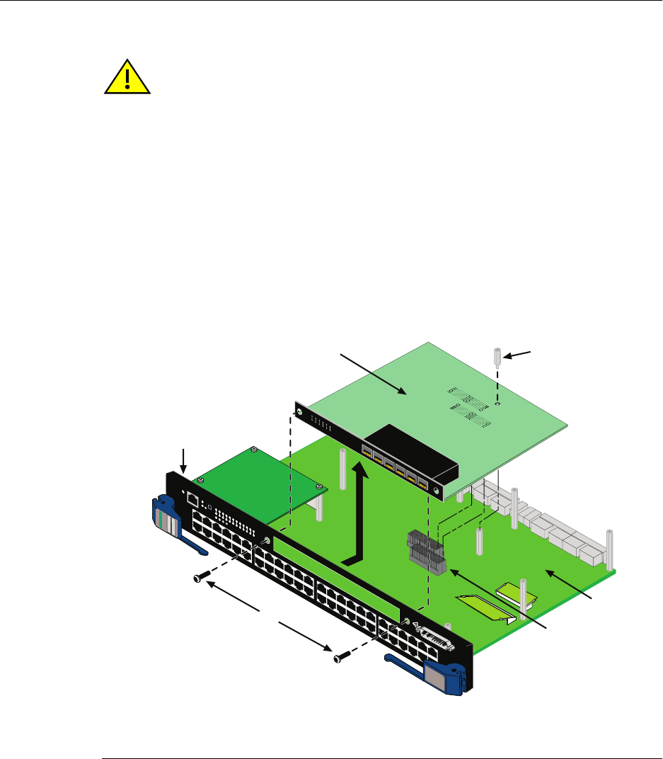
Gaining Access to Memory Modules
DFE-Platinum Series Hardware Installation Guide B-7
DRAM SIMM Replacement Procedure
Afteryouhaveremovedthesafetycoverasdescribedin“RemovingtheSafetyCover”on
page B‐5,proceedto“RemovingtheOptionalNetworkExpansionModule(NEM)”.
Removing the Optional Network Expansion Module (NEM)
RefertoFigure B‐4andproceedasfollows:
1. Attachtheantistaticwriststrap(refertotheinstructionsontheantistaticwriststrap
package).
Figure B-4 Removing the Optional Network Expansion Module
Caution: Observe all Electrostatic Discharge (ESD) precautions when handling sensitive
electronic equipment.
Precaución: Al trabajar con equipos electrónicos sensibles, tome todas las precauciones
de seguridad para evitar descargas de electricidad estática.
1Coverplate screws (2) 4Standoff
2NEM 5Main PC board
3DFE module front panel 6Main board connectors
1X
G
R
O
U
P
1
G
R
O
U
P
2
11X
13X
23X
OFFLINE/
RESET
COM
CPU
MGMT
GROUP
SELECT
GROUP
1
2
3
4
5
6
7
8
9
10
11
12
POE
12 X
14X
24X
G
R
O
U
P
3
25X
35X
26X
36X
G
R
O
U
P
4
37X
47X
38X
48X
1
2
3
4
48V --- 20A MAX
OPTIONAL
POWER INPUT
G
R
O
U
P
1
1X
7H4385-49
FAST ENET
DFE
1
2
3
4
5
6
1
2
3
4
5
6
7G-6MGBIC-A
À
Á
Â
Ã
Å
Ä
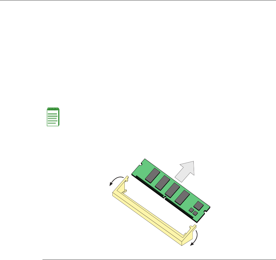
Gaining Access to Memory Modules
B-8 Mode Switch Settings and Option Installations
2. RemovethetwoscrewsfasteningtheNEMtotheDFE modulefrontpaneland
removethestandofffasteningtheNEMtothemainboard.Savethetwoscrewsand
standoffforlaterusetoreinstalltheNEM.
3. LiftandremovetheNEMoffthetwomainPCboardconnectors.Nowyouhave
accesstotheDRAMSIMM.ToreplacetheDRAMSIMM,proceedto“Removingthe
DRAMSIMM”.
Removing the DRAM SIMM
ToremovetheDRAMSIMM,refertoFigure B‐5andproceedasfollows.
1. RefertoFigure B‐5.PushtheconnectorarmsawayfromtheDRAMSIMMtoreleaseit
fromtheconnector.
2. RemovetheDRAMSIMMfromtheconnector.
Figure B-5 Removing the Existing DRAM SIMM
Note: The ejector arms on this connector are not spring-loaded, so they will remain in the
open position until manually closed.
1Connector arms 2Memory module 3 Connector
Â
À
À
Á
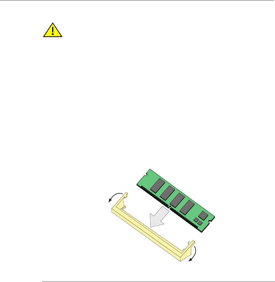
Gaining Access to Memory Modules
DFE-Platinum Series Hardware Installation Guide B-9
Installing the DRAM SIMM
ToinstalltheDRAMSIMM,refertoFigure B‐6andproceedasfollows:
1. Withtheconnectorarmssetintheopenposition,inserttheDRAMSIMMbetweenthe
connectorfingersandpushtheDRAMSIMMintotheconnectoruntilthetabsonthe
twoconnectorarmspullintowardsthealignmentnotches.
2. PushtheDRAMSIMMfurtherintotheconnectoruntilthetwoDRAMSIMM
alignmentnotchesandthetabsonthetwoconnectorarmslocktheDRAMSIMMinto
place.
3. Reinstallthenetworkexpansionmodule.Referto“InstallingtheNetworkExpansion
Module(NEM)”onpage B‐11forinstructions.
4. Reinstallthesafetycover.Referto“ReinstallingtheSafetyCover”onpage B‐13for
instructions.
Figure B-6 Installing the DRAM SIMM
Caution: Observe all Electrostatic Discharge (ESD) precautions when handling sensitive
electronic equipment.
Precaución: Al trabajar con equipos electrónicos sensibles, tome todas las precauciones
de seguridad para evitar descargas de electricidad estática.
1Connector arms 3Connector fingers
2DRAM SIMM 4Alignment notches (2)
Â
À
ÀÁ
Ã
Ã
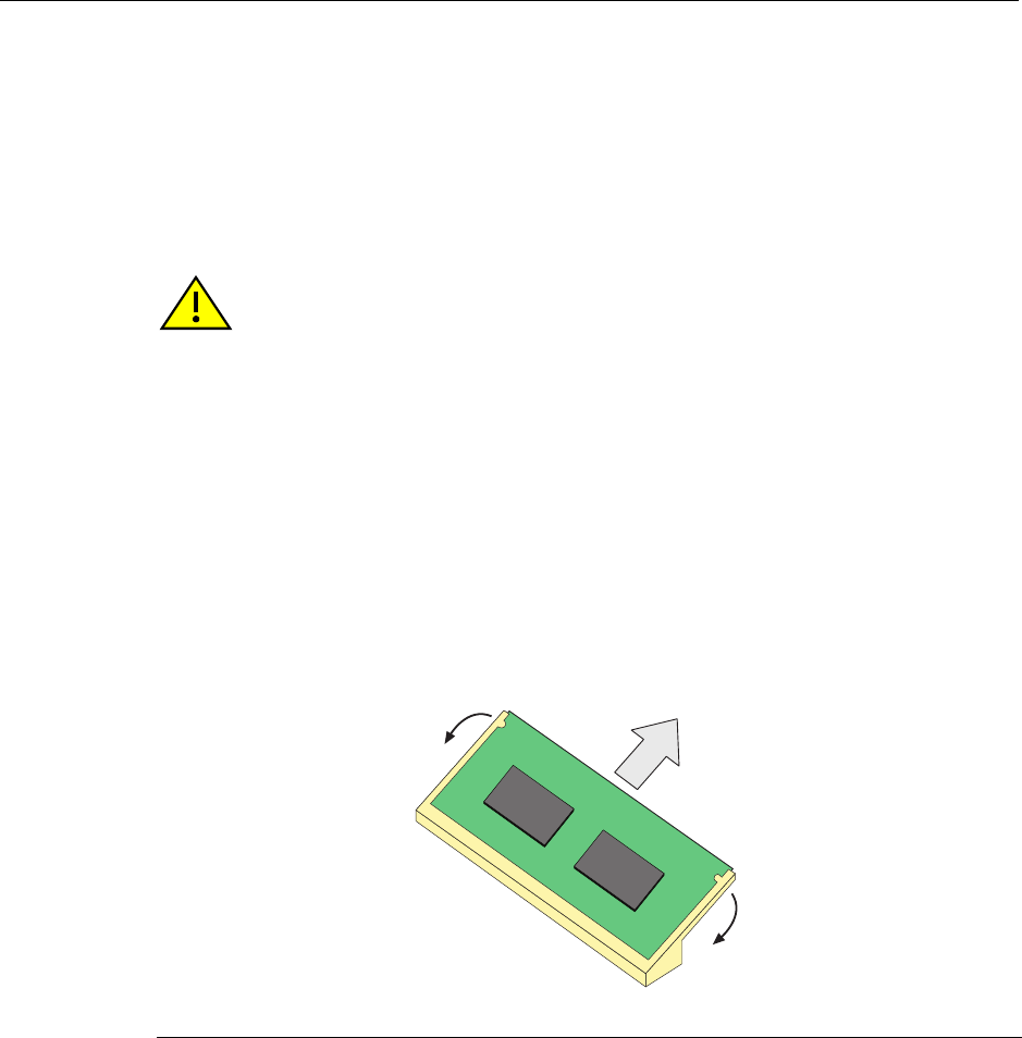
Gaining Access to Memory Modules
B-10 Mode Switch Settings and Option Installations
DIMM Replacement Procedure
IntheeventthattheDualIn‐lineMemoryModule(DIMM)needstobereplaced,the
followingsectionsexplainhowtoremoveandinstalltheDIMM.Ifyouhavequestions
concerningthereplacementoftheDIMM,referto“GettingHelp”onpage xviiifordetails
onhowtocontactEnterasys Networks.
Removing the DIMM
ToremovetheexistingDIMM,proceedasfollows:
1. Removeandsavethesevenscrewsattachingthesafetycovertothestandoffsonthe
mainPCboard.
2. LocatetheDIMMconnectoronthemainPCboard.ReferbacktoFigure B‐2forthe
DIMMlocationonthe7H4385‐49.
3. PushtheconnectorarmsawayfromtheDIMM,asshowninFigure B‐7,and
simultaneouslylifttheDIMMenoughtoreleaseitfromtheconnectorfingers.
Figure B-7 Removing the Existing DIMM
4. RotatetheDIMMupwards,thenremoveitfromtheconnectorfingers.
Caution: Observe all Electrostatic Discharge (ESD) precautions when handling sensitive
electronic equipment.
Precaución: Al trabajar con equipos electrónicos sensibles, tome todas las precauciones
de seguridad para evitar descargas de electricidad estática.
1Connector arms 2DIMM 3 Connector fingers
À
À
Á
Â
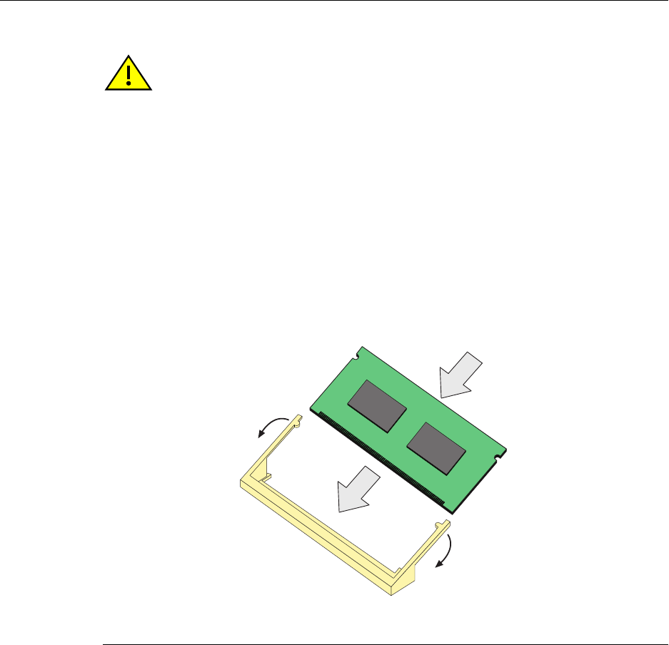
Gaining Access to Memory Modules
DFE-Platinum Series Hardware Installation Guide B-11
Installing the DIMM
ToinstallaDIMM,refertoFigure B‐8andproceedasfollows:
1. InserttheDIMMdownbetweentheconnectorfingers.
2. PivottheDIMMdownwardsothetabsontheconnectorarmsalignwiththetwo
alignmentnotches.Withthetwoconnectorarmsspreadoutward,pushtheDIMM
downbetweentheconnectorarms.Thenreleasethetwoconnectorarmstolockthe
DIMMintoplace.
3. Reinstallthesafetycover.Referto“ReinstallingtheSafetyCover”onpage B‐13for
instructions.
Figure B-8 Installing the DIMM
Installing the Network Expansion Module (NEM)
RefertoFigure B‐9andproceedasfollows:
1. PositiontheNEMsoitsfrontpanelisundertheedgeoftheDFE modulefrontpanel.
2. AlignthetwoNEMconnectorswiththemainboardconnectors.Thenpressstraight
downoverthetwoNEMconnectors,applyingpressureuntiltheyareproperly
seated.
Caution: Observe all Electrostatic Discharge (ESD) precautions when handling sensitive
electronic equipment.
Precaución: Al trabajar con equipos electrónicos sensibles, tome todas las precauciones
de seguridad para evitar descargas de electricidad estática.
1DIMM 3Connector arms
2Connector fingers 4Alignment notches (2)
À
Á
Â
Ã
Ã
Â
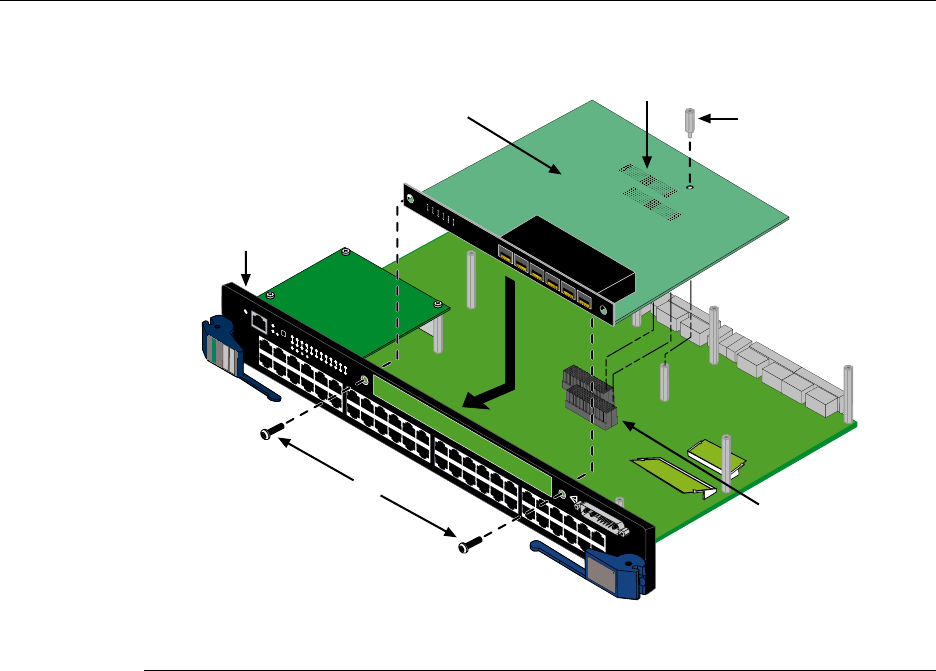
Gaining Access to Memory Modules
B-12 Mode Switch Settings and Option Installations
Figure B-9 Installing the Network Expansion Module
3. UsetwoofthesavedcoverplatescrewstofastentheNEMtotheDFE modulefront
panel,butdonottightenscrewsatthistime.
4. InsertthesavedstandoffthroughtheNEMtothestandoffonthemainboard.Screw
inthestandoff,butdonottightenscrewsatthistime.
5. Tightenthetwocoverplatescrewsfirst,thenthestandoff.
1NEM 3NEM connectors 5Coverplate screws (2)
2Front panel 4Main board connectors 6Standoff
1X
G
R
O
U
P
1
G
R
O
U
P
2
11X
13X
23X
OFFLINE/
RESET
COM
CPU
MGMT
GROUP
SELECT
GROUP
1
2
3
4
5
6
7
8
9
10
11
12
POE
12 X
14X
24X
G
R
O
U
P
3
25X
35X
26X
36X
G
R
O
U
P
4
37X
47X
38X
48X
1
2
3
4
48V --- 20A MAX
OPTIONAL
POWER INPUT
G
R
O
U
P
1
1X
7H4385-49
FAST ENET
DFE
1
2
3
4
5
6
1
2
3
4
5
6
7G-6MGBIC-A
Ä
À
Á
Â
Ã
Å

Gaining Access to Memory Modules
DFE-Platinum Series Hardware Installation Guide B-13
Reinstalling the Safety Cover
Toinstallthesafetycover,refertoFigure B‐10andproceedasfollows:
1. Locatethesevenscrewssavedintheprocedure“RemovingtheSafetyCover”on
page B‐5.
2. Fastenthesafetycovertothestandoffsusingthesevenscrews.Thiscompletesthe
safetycoverinstallation.
Warning: The safety cover protects you from exposure to an energy hazard in excess of
240 Volt-Amperes. Never operate the DFE module without the safety cover installed.
Advertencia: La cubierta de seguridad lo protege de exponerlo al riesgo de energía en
exceso de 240 Volt -Amperes.Nunca se debe opererar el modulo de DFE sin la cobertura
de seguridad instalada.
Warnhinweis: Die Sicherheitsabdeckung schützt vor Stromstössen von bis zu 240 VA.
Bitte nehmen Sie niemals die DFE Module ohne die Abdeckung in Betrieb.
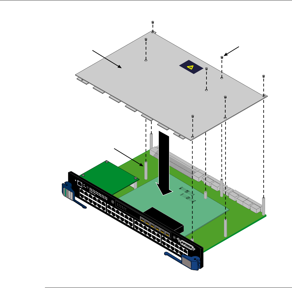
Gaining Access to Memory Modules
B-14 Mode Switch Settings and Option Installations
Figure B-10 Installing the Safety Cover
1Safety cover 2Screws (7) 3Standoff (7)
1
2
3
4
5
6
1
2
3
4
5
6
7G-6MGBIC-A
1X
G
R
O
U
P
1
G
R
O
U
P
2
11X
13X
23X
OFFLINE/
RESET
COM
CPU
MGMT
GROUP
SELECT
GROUP
1
2
3
4
5
6
7
8
9
10
11
12
POE
12 X
14X
24X
G
R
O
U
P
3
25X
35X
26X
36X
G
R
O
U
P
4
37X
47X
38X
48X
1
2
3
4
48V --- 20A MAX
OPTIONAL
POWER INPUT
G
R
O
U
P
1
1X
7H4385-49
FAST ENET
DFE
Á
À
Â

DFE-Platinum Series Hardware Installation Guide C-1
C
About PoE (Power over Ethernet)
ThisappendixprovidesanoverviewofPoweroverEthernetTechnologyandhowitis
implementedinrelationtothe7H4385‐49.
Overview
PoweroverEthernet(PoE)referstotheabilitytoprovideoperationalpowerthroughthe
sameEthernetcablingtoaPD(powereddevice)connectedtoadatanetwork.Modern
Ethernetimplementationsemploydifferentialsignalsovertwistedpaircables.This
requiresaminimumoftwotwistedpairsforasinglephysicallink.Bothendsofthecable
areisolatedwithtransformersblockinganyDCorcommonmodevoltageonthesignal
pair.PoEexploitsthisfactbyusingtwotwistedpairsasthetwoconductorstosupplya
directcurrent.Onepaircarriesthepowersupplycurrentandtheotherpairprovidesa
pathforthereturncurrent.WhileseveralproprietarylegacyimplementationsofPoE
havebeendeployedbyLANequipmentvendors,in2003theIEEEpublishedtheIEEE
802.3af‐2003specification,whichispartofthe802.3suiteofstandards.
The7H4385‐49isfullycompliantwiththeIEEE802.3afstandard.Itsupportsthestandard
resistorbaseddetectionmethod,aswellasACdisconnectcapability.The7H4385‐49is
alsocapableofsupplyingthemaximumspecifiedcurrenttoallportssimultaneously.
EachPDhasaPDC(PoweredDeviceClassification)thatistransmittedtotheDFEmodule
forpowermanagementpurposes.Table C‐1liststheclassificationsandtheassociated
powerranges.
Table C-1 Powered Device Classifications
Class Usage PD Maximum Power Range Usage
0 Default 0.44 to 12.95 Watts
1 Optional 0.44 to 3.84 Watts
2 Optional 3.84 to 6.49 Watts
3 Optional 6.49 to 12.95 Watts
4 Not Allowed Reserved for Future Use

Overview
C-2 About PoE (Power over Ethernet)
Proprietary PD Detection
The7H4385‐49supportsasubsetofthecurrentlydeployedproprietaryPoEmethods.
ThisincludessupportforCiscoPDs,includingaproprietarycapacitorbaseddetection
scheme.
Power Interface
The7H4385‐49caninterfacewithanexternal48VpowersupplythatresidesinaMatrix
N5chassisorfromaseparateMatrixN‐POEPowerSystem.
Matrix N5 Backplane 48 Vdc Interface
The7H4385‐49hasaconnectorthatinterfaceswiththebackplaneoftheN5chassisfor
48 Vdcpower.Thispowerconnectiononthe7H4385‐49isfused,hasEMIsuppression
componentsforthisinterface,andcansupportasustainedoutputcurrentof20 A.
Front Panel 48 Vdc Interface
The48VdcOptionalPowerInputconnectoronthe7H4385‐49frontpanelprovidesa
powerinterfaceconnectionforanEnterasysMatrixN‐POEPowerSystem,which
providesthe48Vdc,20Amperesofpowerandreturnaswellasthepowersupplystatus
signals.ThestatussignalsindicatethepresenceandoperatingstateofeachMatrixN‐POE
PowerSystempowersupplies.This48VdcOptionalPowerInputinterfaceisnotfusedas
theN‐PoEPowerSystemhasacircuitbreakerforeachPoEswitchmodulepowerfeed.
Warning: The DFE module is shipped with a cover over its 48 Vdc Optional Power Input
connector. Do not remove this cover when the DFE module is installed in an N5 chassis.
This cover is removed only when you connect a 48 Vdc power cable from the Enterasys
N-POE Power System.
Advertencia: El modulo DFE es embarcado con una cubierta sobre su conector de poder
opcional de 48 Vdc. No remover esta cubierta cuando el modulo DFE es instalado en un
chassis N5. Esta cubierta debe removerse unicamente cuando se conecta el cable de
poder de 48 Vdc hacia el Sistema de Enterasys de Energia por Cable (Enterasys N-POE
Power System).
Warnhinweis: Im Auslieferungszustand der DFE Module stülpt eine Schutzkappe über
dem 48V Gleichspannungs-Anschluss, die nur dann abgezogen werden darf, wenn ein
Enterasys N-POE Power System angeschlossen wird. Keinesfalls darf diese Schutzkappe
abgezogen werden, wenn das DFE Modul in einem N5 Chassis installiert wird.

Overview
DFE-Platinum Series Hardware Installation Guide C-3
PoE Port Status LEDs
ThePoEportstatusofeach10/100Mbpsfront‐panelportisindicatedbythetwo‐colorRX
andTXLEDdisplayforeachport.ToobservethePoEportstatusindications,youmust
switchtheDFEmodulemanagementsystemfromthedefaultRX/TXStatusModetothe
PoEPortStatusModeusingtheDFEmodulefront‐panelGROUPSELECTswitch.The
switchoperationandadescriptionofhowtousetheLEDindicationsaredescribedin
“UsingLANVIEW”onpage 4‐1.
Table C‐2providesabriefdescriptionofeachportstatusRX/TXLEDdisplay.
Table C-2 PoE Status LED Indications
PoE Port Status RX LED TX LED
Port is powered on GREEN OFF
Port is off due to overload OFF RED
Port is off due to power management RED OFF
Port is off for other reason OFF OFF

Overview
C-4 About PoE (Power over Ethernet)

Index-1
Index
Numerics
100BASE-TX
connection 3-15
requirements 2-3
10BASE-T
connection 3-15
requirements 2-2
7H4385-49
introduction to 1-3, 1-4
specifications for A-1
C
Cable connections
7H4382-49 3-15
UTP 3-15
Cable specifications
100BASE-TX network 2-3
10BASE-T network 2-2
CLI command
introduction to 1-5
COM port connections
IBM PC or Compatible Device 3-20
Modem 3-22
VT Series Terminal 3-21
what is needed 3-20
Connecting to the network 3-15
Connectivity
DFE module and network expansion module 1-5
introduction to 1-4
Console port
pinout assignments A-2
D
DFE Modules and optional NEM
introduction to 1-3
DFE series modules
overview of capabilities 1-2
DIMM
installing DIMM B-11
replacement procedures for B-3
E
Electromagnetic Compatibility (EMC)
requirements A-3
F
FTM bridge function
introduction to 2-2
G
Getting Help
instructions for xviii
GROUP SELECT button
use of the 4-2
I
Installation
connecting to the Network 3-15
module into Matrix E7 or N7 chassis 3-7
module into Matrix N1, N3, N5 chassis 3-11
optional network expansion module 3-3
L
LANVIEW Diagnostic LEDs
use of 1-6
LANVIEW LEDs
use of 4-1
Local Management
COM port connections 3-20
introduction to 1-5
Login
administratively configured 3-28
M
Management
use of 1-5
Management (MGMT) LED
function of 4-1
Matrix E7 or N7 chassis
module installation into 3-7
Matrix N1, N3, N5 chassis
7H4385-49 installation into 3-11
Memory
replacement of DIMM B-10
replacement of DRAM SIMM B-7
Memory locations
DIMM and SIMM B-3
Mode Switch
setting of B-2
Module coverplate
removal of B-7
Module features 1-3
N
NEM 3-3
Network
connecting to 3-15
Index-2
Network Requirements
list of 2-1
Notices
General ii
O
Offline/reset switch
use of 4-9
Optional network expansion module
installation of 3-3
P
Pinout assignments
console port A-2
Pinouts
crossover 3-17, 3-18
straight-through 3-18, 3-19
PoE (Power over Ethernet)
overview of C-1
PoE operation
power connection for 3-14
PoE port status
viewing of 4-2
R
Receive LEDs
viewing of 4-2
Regulatory Compliance A-3
Related manuals
obtaining xvi
Required tools B-1
S
Safety requirements A-3
Specifications A-1
7H4385-49 A-1
Standards compatibility 1-5
T
Transmit LEDs
viewing of 4-2
Troubleshooting 4-1
checklist for 4-6
U
Unpacking the module 3-2
User Personalized Networks (UPN) See Secure
Networks Policy Support.
UTP cable connections
front panel 3-15
V
Viewing Receive and Transmit Activity
instructions for 4-2
W
WebView
introduction to 1-5
