Enterasys Networks N Standalone Nsa Series Users Manual DFEConfig Guide
N Standalone (NSA) Series 3884ec60-08cc-bac4-b176-2f6590d63c88
N Standalone (NSA) Series to the manual 3884ec60-08cc-bac4-b176-2f6590d63c88
2015-02-04
: Enterasys-Networks Enterasys-Networks-N-Standalone-Nsa-Series-Users-Manual-366850 enterasys-networks-n-standalone-nsa-series-users-manual-366850 enterasys-networks pdf
Open the PDF directly: View PDF ![]() .
.
Page Count: 1372 [warning: Documents this large are best viewed by clicking the View PDF Link!]
- Enterasys Matrix® N Standalone (NSA) Series Configuration Guide
- Notice
- Contents
- About This Guide
- Introduction
- Startup and General Configuration
- 2.1 Startup and General Configuration Summary
- 2.1.1 Factory Default Settings
- 2.1.2 CLI “Command Defaults” Descriptions
- 2.1.3 CLI Command Modes
- 2.1.4 Using WebView
- 2.1.5 Process Overview: CLI Startup and General Configuration
- 2.1.6 Starting and Navigating the Command Line Interface
- 2.1.6.1 Using a Console Port Connection
- 2.1.6.2 Logging in with a Default User Account
- 2.1.6.3 Logging in with Administratively Configured Account
- 2.1.6.4 Using a Telnet Connection
- 2.1.6.5 Getting Help with CLI Syntax
- 2.1.6.6 Using Context-Sensitive Help
- 2.1.6.7 Performing Keyword Lookups
- 2.1.6.8 Displaying Scrolling Screens
- 2.1.6.9 Abbreviating and Completing Commands
- 2.1.6.10 Using the Spacebar Auto Complete Function
- 2.1.7 Configuring the Line Editor
- 2.2 General Configuration Command Set
- 2.2.1 Setting User Accounts and Passwords
- 2.2.2 Managing the Management Authentication Notification MIB
- 2.2.3 Setting Basic Device Properties
- 2.2.3.1 show ip address
- 2.2.3.2 set ip address
- 2.2.3.3 clear ip address
- 2.2.3.4 show ip gratuitous-arp
- 2.2.3.5 set ip gratuitous-arp
- 2.2.3.6 clear ip gratuitous-arp
- 2.2.3.7 show system
- 2.2.3.8 show system hardware
- 2.2.3.9 show system utilization
- 2.2.3.10 set system utilization threshold
- 2.2.3.11 clear system utilization
- 2.2.3.12 show time
- 2.2.3.13 set time
- 2.2.3.14 show summertime
- 2.2.3.15 set summertime
- 2.2.3.16 set summertime date
- 2.2.3.17 set summertime recurring
- 2.2.3.18 clear summertime
- 2.2.3.19 set prompt
- 2.2.3.20 set cli completion
- 2.2.3.21 loop
- 2.2.3.22 show banner motd
- 2.2.3.23 set banner motd
- 2.2.3.24 clear banner motd
- 2.2.3.25 show version
- 2.2.3.26 set system name
- 2.2.3.27 set system location
- 2.2.3.28 set system contact
- 2.2.3.29 set width
- 2.2.3.30 set length
- 2.2.3.31 show logout
- 2.2.3.32 set logout
- 2.2.3.33 show physical alias
- 2.2.3.34 set physical alias
- 2.2.3.35 clear physical alias
- 2.2.3.36 show physical assetid
- 2.2.3.37 set physical assetid
- 2.2.3.38 clear physical assetid
- 2.2.4 Activating Licensed Features
- 2.2.5 Downloading a New Firmware Image
- 2.2.6 Reviewing and Selecting a Boot Firmware Image
- 2.2.7 Starting and Configuring Telnet
- 2.2.8 Managing Configuration and Image Files
- 2.2.9 Enabling or Disabling the Path MTU Discovery Protocol
- 2.2.10 Pausing, Clearing and Closing the CLI
- 2.2.11 Resetting the Device
- 2.2.12 Gathering Technical Support Information
- 2.3 Preparing the Device for Router Mode
- 2.1 Startup and General Configuration Summary
- Configuring Discovery Protocols
- 3.1 Overview
- 3.2 Discovery Protocols Command Set
- 3.2.1 Displaying Neighbors
- 3.2.2 Enterasys Discovery Protocol
- 3.2.3 Cisco Discovery Protocol
- 3.2.4 Link Layer Discovery Protocol and LLDP-MED
- 3.2.4.1 show lldp
- 3.2.4.2 show lldp port status
- 3.2.4.3 show lldp port trap
- 3.2.4.4 show lldp port tx-tlv
- 3.2.4.5 show lldp port location-info
- 3.2.4.6 show lldp port local-info
- 3.2.4.7 show lldp port remote-info
- 3.2.4.8 show lldp port network-policy
- 3.2.4.9 set lldp tx-interval
- 3.2.4.10 set lldp hold-multiplier
- 3.2.4.11 set lldp trap-interval
- 3.2.4.12 set lldp med-fast-repeat
- 3.2.4.13 set lldp port status
- 3.2.4.14 set lldp port trap
- 3.2.4.15 set lldp port med-trap
- 3.2.4.16 set lldp port location-info
- 3.2.4.17 set lldp port tx-tlv
- 3.2.4.18 set lldp port network-policy
- 3.2.4.19 clear lldp
- 3.2.4.20 clear lldp port status
- 3.2.4.21 clear lldp port trap
- 3.2.4.22 clear lldp port med-trap
- 3.2.4.23 clear lldp port location-info
- 3.2.4.24 clear lldp port network-policy
- 3.2.4.25 clear lldp port tx-tlv
- Port Configuration
- 4.1 Port Configuration Summary
- 4.2 Process Overview: Port Configuration
- 4.3 Port Configuration Command Set
- 4.3.1 Setting Console Port Properties
- 4.3.1.1 show console
- 4.3.1.2 clear console
- 4.3.1.3 show console baud
- 4.3.1.4 set console baud
- 4.3.1.5 clear console baud
- 4.3.1.6 show console flowcontrol
- 4.3.1.7 set console flowcontrol
- 4.3.1.8 clear console flowcontrol
- 4.3.1.9 show console bits
- 4.3.1.10 set console bits
- 4.3.1.11 clear console bits
- 4.3.1.12 show console stopbits
- 4.3.1.13 set console stopbits
- 4.3.1.14 clear console stopbits
- 4.3.1.15 show console parity
- 4.3.1.16 set console parity
- 4.3.1.17 clear console parity
- 4.3.2 Reviewing Port Status
- 4.3.3 Disabling / Enabling and Naming Ports
- 4.3.4 Setting Speed and Duplex Mode
- 4.3.5 Enabling / Disabling Jumbo Frame Support
- 4.3.6 Setting Auto-Negotiation and Advertised Ability
- 4.3.7 Setting Flow Control
- 4.3.8 Configuring Link Traps and Link Flap Detection
- 4.3.8.1 show port trap
- 4.3.8.2 set port trap
- 4.3.8.3 show linkflap
- 4.3.8.4 set linkflap globalstate
- 4.3.8.5 set linkflap
- 4.3.8.6 set linkflap interval
- 4.3.8.7 set linkflap action
- 4.3.8.8 clear linkflap action
- 4.3.8.9 set linkflap threshold
- 4.3.8.10 set linkflap downtime
- 4.3.8.11 clear linkflap down
- 4.3.8.12 clear linkflap
- 4.3.9 Configuring Broadcast Suppression
- 4.3.1 Setting Console Port Properties
- 4.4 Configuring Port Mirroring
- 4.5 Configuring LACP
- 4.5.1 LACP Operation
- 4.5.2 LACP Terminology
- 4.5.3 Matrix Series Usage Considerations
- 4.5.4 Configuring Link Aggregation
- 4.5.4.1 show lacp
- 4.5.4.2 set lacp
- 4.5.4.3 clear lacp state
- 4.5.4.4 set lacp asyspri
- 4.5.4.5 set lacp aadminkey
- 4.5.4.6 clear lacp
- 4.5.4.7 set lacp static
- 4.5.4.8 clear lacp static
- 4.5.4.9 show lacp singleportlag
- 4.5.4.10 set singleportlag
- 4.5.4.11 clear singleportlag
- 4.5.4.12 show port lacp
- 4.5.4.13 set port lacp
- 4.5.4.14 clear port lacp
- 4.5.4.15 show lacp flowRegeneration
- 4.5.4.16 set lacp flowRegeneration
- 4.5.4.17 clear lacp flowRegeneration
- 4.5.4.18 show lacp outportAlgorithm
- 4.5.4.19 set lacp outportAlgorithm
- 4.5.4.20 clear lacp outportAlgorithm
- SNMP Configuration
- 5.1 SNMP Configuration Summary
- 5.2 Process Overview: SNMP Configuration
- 5.3 SNMP Configuration Command Set
- 5.3.1 Reviewing SNMP Statistics
- 5.3.2 Configuring SNMP Users, Groups and Communities
- 5.3.3 Configuring SNMP Access Rights
- 5.3.4 Configuring SNMP MIB Views
- 5.3.5 Configuring SNMP Target Parameters
- 5.3.6 Configuring SNMP Target Addresses
- 5.3.7 Configuring SNMP Notification Parameters
- 5.3.8 Creating a Basic SNMP Trap Configuration
- Spanning Tree Configuration
- 6.1 Spanning Tree Configuration Summary
- 6.2 Spanning Tree Configuration Command Set
- 6.2.1 Configuring Spanning Tree Bridge Parameters
- 6.2.1.1 show spantree stats
- 6.2.1.2 show spantree version
- 6.2.1.3 set spantree version
- 6.2.1.4 clear spantree version
- 6.2.1.5 show spantree stpmode
- 6.2.1.6 set spantree stpmode
- 6.2.1.7 clear spantree stpmode
- 6.2.1.8 show spantree maxconfigurablestps
- 6.2.1.9 set spantree maxconfigurablestps
- 6.2.1.10 clear spantree maxconfigurablestps
- 6.2.1.11 show spantree mstilist
- 6.2.1.12 set spantree msti
- 6.2.1.13 clear spantree msti
- 6.2.1.14 show spantree mstmap
- 6.2.1.15 set spantree mstmap
- 6.2.1.16 clear spantree mstmap
- 6.2.1.17 show spantree vlanlist
- 6.2.1.18 show spantree mstcfgid
- 6.2.1.19 set spantree mstcfgid
- 6.2.1.20 clear spantree mstcfgid
- 6.2.1.21 show spantree bridgeprioritymode
- 6.2.1.22 set spantree bridgeprioritymode
- 6.2.1.23 clear spantree bridgeprioritymode
- 6.2.1.24 show spantree priority
- 6.2.1.25 set spantree priority
- 6.2.1.26 clear spantree priority
- 6.2.1.27 show spantree bridgehellomode
- 6.2.1.28 set spantree bridgehellomode
- 6.2.1.29 clear spantree bridgehellomode
- 6.2.1.30 show spantree hello
- 6.2.1.31 set spantree hello
- 6.2.1.32 clear spantree hello
- 6.2.1.33 show spantree maxage
- 6.2.1.34 set spantree maxage
- 6.2.1.35 clear spantree maxage
- 6.2.1.36 show spantree fwddelay
- 6.2.1.37 set spantree fwddelay
- 6.2.1.38 clear spantree fwddelay
- 6.2.1.39 show spantree autoedge
- 6.2.1.40 set spantree autoedge
- 6.2.1.41 clear spantree autoedge
- 6.2.1.42 show spantree legacypathcost
- 6.2.1.43 set spantree legacypathcost
- 6.2.1.44 clear spantree legacypathcost
- 6.2.1.45 show spantree tctrapsuppress
- 6.2.1.46 set spantree tctrapsuppress
- 6.2.1.47 clear spantree tctrapsuppress
- 6.2.1.48 show spantree txholdcount
- 6.2.1.49 set spantree txholdcount
- 6.2.1.50 clear spantree txholdcount
- 6.2.1.51 show spantree maxhops
- 6.2.1.52 set spantree maxhops
- 6.2.1.53 clear spantree maxhops
- 6.2.1.54 show spantree spanguard
- 6.2.1.55 set spantree spanguard
- 6.2.1.56 clear spantree spanguard
- 6.2.1.57 show spantree spanguardtimeout
- 6.2.1.58 set spantree spanguardtimeout
- 6.2.1.59 clear spantree spanguardtimeout
- 6.2.1.60 show spantree spanguardlock
- 6.2.1.61 clear / set spantree spanguardlock
- 6.2.1.62 show spantree spanguardtrapenable
- 6.2.1.63 set spantree spanguardtrapenable
- 6.2.1.64 clear spantree spanguardtrap enable
- 6.2.1.65 show spantree backuproot
- 6.2.1.66 set spantree backuproot
- 6.2.1.67 clear spantree backuproot
- 6.2.1.68 show spantree backuproottrapendable
- 6.2.1.69 set spantree backuproottrapenable
- 6.2.1.70 clear spantree backuproottrapenable
- 6.2.1.71 show spantree newroottrapendable
- 6.2.1.72 set spantree newroottrapenable
- 6.2.1.73 clear spantree newroottrapenable
- 6.2.1.74 clear spantree default
- 6.2.1.75 show spantree debug
- 6.2.1.76 clear spantree debug
- 6.2.2 Configuring Spanning Tree Port Parameters
- 6.2.2.1 show spantree portenable
- 6.2.2.2 set spantree portenable
- 6.2.2.3 clear spantree portenable
- 6.2.2.4 show spantree portadmin
- 6.2.2.5 set spantree portadmin
- 6.2.2.6 clear spantree portadmin
- 6.2.2.7 set spantree protomigration
- 6.2.2.8 show spantree portstate
- 6.2.2.9 show spantree blockedports
- 6.2.2.10 show spantree portpri
- 6.2.2.11 set spantree portpri
- 6.2.2.12 clear spantree portpri
- 6.2.2.13 set spantree porthello
- 6.2.2.14 clear spantree porthello
- 6.2.2.15 show spantree portcost
- 6.2.2.16 show spantree adminpathcost
- 6.2.2.17 set spantree adminpathcost
- 6.2.2.18 clear spantree adminpathcost
- 6.2.2.19 show spantree adminedge
- 6.2.2.20 set spantree adminedge
- 6.2.2.21 clear spantree adminedge
- 6.2.2.22 show spantree operedge
- 6.2.2.23 show spantree adminpoint
- 6.2.2.24 show spantree operpoint
- 6.2.2.25 set spantree adminpoint
- 6.2.2.26 clear spantree adminpoint
- 6.2.3 Configuring Spanning Tree Loop Protect Features
- 6.2.3.1 set spantree lp
- 6.2.3.2 show spantree lp
- 6.2.3.3 clear spantree lp
- 6.2.3.4 show spantree lplock
- 6.2.3.5 clear spantree lplock
- 6.2.3.6 set spantree lpcapablepartner
- 6.2.3.7 show spantree lpcapablepartner
- 6.2.3.8 clear spantree lpcapablepartner
- 6.2.3.9 set spantree lpthreshold
- 6.2.3.10 show spantree lpthreshold
- 6.2.3.11 clear spantree lpthreshold
- 6.2.3.12 set spantree lpwindow
- 6.2.3.13 show spantree lpwindow
- 6.2.3.14 clear spantree lpwindow
- 6.2.3.15 set spantree lptrapenable
- 6.2.3.16 show spantree lptrapenable
- 6.2.3.17 clear spantree lptrapenable
- 6.2.3.18 set spantree disputedbpduthreshold
- 6.2.3.19 show spantree disputedbpduthreshold
- 6.2.3.20 clear spantree disputedbpduthreshold
- 6.2.3.21 show spantree nonforwardingreason
- 6.2.1 Configuring Spanning Tree Bridge Parameters
- 802.1Q VLAN Configuration
- 7.1 VLAN Configuration Summary
- 7.2 Process Overview: 802.1Q VLAN Configuration
- 7.3 VLAN Configuration Command Set
- Policy Classification Configuration
- 8.1 Policy Classification Configuration Summary
- 8.2 Process Overview: Policy Classification Configuration
- 8.3 Policy Classification Configuration Command Set
- 8.3.1 Configuring Policy Profiles
- 8.3.1.1 show policy profile
- 8.3.1.2 set policy profile
- 8.3.1.3 clear policy profile
- 8.3.1.4 show policy invalid
- 8.3.1.5 set policy invalid action
- 8.3.1.6 clear policy invalid action
- 8.3.1.7 set port tci overwrite
- 8.3.1.8 show policy accounting
- 8.3.1.9 set policy accounting
- 8.3.1.10 clear policy accounting
- 8.3.1.11 show policy syslog
- 8.3.1.12 set policy syslog
- 8.3.1.13 clear policy syslog
- 8.3.1.14 set policy maptable
- 8.3.1.15 show policy maptable
- 8.3.1.16 clear policy maptable
- 8.3.2 Assigning Classification Rules to Policy Profiles
- 8.3.2.1 show policy rule
- 8.3.2.2 show policy capability
- 8.3.2.3 set policy classify
- 8.3.2.4 set policy rule
- 8.3.2.5 clear policy rule
- 8.3.2.6 clear policy all-rules
- 8.3.2.7 set policy port
- 8.3.2.8 show policy allowed-type
- 8.3.2.9 set policy allowed-type
- 8.3.2.10 clear policy allowed-type
- 8.3.2.11 clear policy port-hit
- 8.3.3 Configuring Policy Class of Service (CoS)
- 8.3.3.1 show cos state
- 8.3.3.2 set cos state
- 8.3.3.3 show cos port-type
- 8.3.3.4 show cos unit
- 8.3.3.5 show cos port-config
- 8.3.3.6 set cos port-config irl
- 8.3.3.7 clear cos port-config irl
- 8.3.3.8 set cos port-config txq
- 8.3.3.9 clear cos port-config txq
- 8.3.3.10 show cos port-resource
- 8.3.3.11 set cos port-resource irl
- 8.3.3.12 clear cos port-resource irl
- 8.3.3.13 set cos port-resource txq
- 8.3.3.14 clear cos port-resource txq
- 8.3.3.15 show cos reference
- 8.3.3.16 set cos reference irl
- 8.3.3.17 clear cos reference irl
- 8.3.3.18 set cos reference txq
- 8.3.3.19 clear cos reference txq
- 8.3.3.20 show cos settings
- 8.3.3.21 set cos settings
- 8.3.3.22 clear cos settings
- 8.3.3.23 show cos violation irl
- 8.3.3.24 clear cos violation irl
- 8.3.3.25 clear cos all-entries
- 8.3.1 Configuring Policy Profiles
- Port Priority and Rate Limiting Configuration
- IGMP Configuration
- 10.1 About IP Multicast Group Management
- 10.2 IGMP Configuration Summary
- 10.3 Process Overview: IGMP Configuration
- 10.4 IGMP Configuration Command Set
- 10.4.1 Enabling / Disabling IGMP
- 10.4.2 Configuring IGMP
- 10.4.2.1 show igmp query
- 10.4.2.2 set igmp query-enable
- 10.4.2.3 set igmp query-disable
- 10.4.2.4 show igmp grp-full-action
- 10.4.2.5 set igmp grp-full-action
- 10.4.2.6 show igmp config
- 10.4.2.7 set igmp config
- 10.4.2.8 set igmp delete
- 10.4.2.9 show igmp groups
- 10.4.2.10 show igmp static
- 10.4.2.11 set igmp add-static
- 10.4.2.12 set igmp remove-static
- 10.4.2.13 show igmp protocols
- 10.4.2.14 set igmp protocols
- 10.4.2.15 clear igmp protocols
- 10.4.2.16 show igmp vlan
- 10.4.2.17 show igmp reporters
- 10.4.2.18 show igmp flow
- 10.4.2.19 show igmp counters
- 10.4.2.20 show igmp number-groups
- Logging and Network Management
- 11.1 Process Overview: Network Management
- 11.2 Logging And Network Management Command Set
- 11.2.1 Configuring System Logging
- 11.2.1.1 show logging all
- 11.2.1.2 show logging server
- 11.2.1.3 set logging server
- 11.2.1.4 clear logging server
- 11.2.1.5 show logging default
- 11.2.1.6 set logging default
- 11.2.1.7 clear logging default
- 11.2.1.8 show logging application
- 11.2.1.9 set logging application
- 11.2.1.10 clear logging application
- 11.2.1.11 show logging local
- 11.2.1.12 set logging local
- 11.2.1.13 clear logging local
- 11.2.1.14 set logging here
- 11.2.1.15 clear logging here
- 11.2.1.16 show logging buffer
- 11.2.2 Monitoring Network Events and Status
- 11.2.3 Configuring SMON
- 11.2.4 Configuring RMON
- 11.2.4.1 show rmon stats
- 11.2.4.2 set rmon stats
- 11.2.4.3 clear rmon stats
- 11.2.4.4 show rmon history
- 11.2.4.5 set rmon history
- 11.2.4.6 clear rmon history
- 11.2.4.7 show rmon alarm
- 11.2.4.8 set rmon alarm properties
- 11.2.4.9 set rmon alarm status
- 11.2.4.10 clear rmon alarm
- 11.2.4.11 show rmon event
- 11.2.4.12 set rmon event properties
- 11.2.4.13 set rmon event status
- 11.2.4.14 clear rmon event
- 11.2.4.15 show rmon host
- 11.2.4.16 set rmon host properties
- 11.2.4.17 set rmon host status
- 11.2.4.18 clear rmon host
- 11.2.4.19 show rmon topN
- 11.2.4.20 set rmon topN properties
- 11.2.4.21 set rmon topN status
- 11.2.4.22 clear rmon topN
- 11.2.4.23 show rmon matrix
- 11.2.4.24 set rmon matrix properties
- 11.2.4.25 set rmon matrix status
- 11.2.4.26 clear rmon matrix
- 11.2.4.27 show rmon channel
- 11.2.4.28 set rmon channel
- 11.2.4.29 clear rmon channel
- 11.2.4.30 show rmon filter
- 11.2.4.31 set rmon filter
- 11.2.4.32 clear rmon filter
- 11.2.4.33 show rmon capture
- 11.2.4.34 set rmon capture
- 11.2.4.35 clear rmon capture
- 11.2.5 Managing Switch Network Addresses and Routes
- 11.2.5.1 show arp
- 11.2.5.2 set arp
- 11.2.5.3 clear arp
- 11.2.5.4 show rad
- 11.2.5.5 set rad
- 11.2.5.6 show ip route
- 11.2.5.7 traceroute
- 11.2.5.8 set ip route
- 11.2.5.9 clear ip route
- 11.2.5.10 show port mac
- 11.2.5.11 show mac
- 11.2.5.12 set mac
- 11.2.5.13 clear mac
- 11.2.5.14 show newaddrtraps
- 11.2.5.15 set newaddrtraps
- 11.2.5.16 show movedaddrtrap
- 11.2.5.17 set movedaddrtrap
- 11.2.6 Configuring Simple Network Time Protocol (SNTP)
- 11.2.6.1 show sntp
- 11.2.6.2 set sntp client
- 11.2.6.3 clear sntp client
- 11.2.6.4 set sntp server
- 11.2.6.5 clear sntp server
- 11.2.6.6 set sntp broadcastdelay
- 11.2.6.7 clear sntp broadcast delay
- 11.2.6.8 set sntp poll-interval
- 11.2.6.9 clear sntp poll-interval
- 11.2.6.10 set sntp poll-retry
- 11.2.6.11 clear sntp poll-retry
- 11.2.6.12 set sntp poll-timeout
- 11.2.6.13 clear sntp poll-timeout
- 11.2.6.14 show timezone
- 11.2.6.15 set timezone
- 11.2.6.16 clear timezone
- 11.2.7 Configuring Node Aliases
- 11.2.8 Configuring NetFlow
- 11.2.8.1 show netflow
- 11.2.8.2 set netflow cache
- 11.2.8.3 clear netflow cache
- 11.2.8.4 set netflow export-destination
- 11.2.8.5 clear netflow export-destination
- 11.2.8.6 set netflow export-interval
- 11.2.8.7 clear netflow export-interval
- 11.2.8.8 set netflow port
- 11.2.8.9 clear netflow port
- 11.2.8.10 set netflow export-version
- 11.2.8.11 clear netflow export-version
- 11.2.8.12 set netflow template
- 11.2.8.13 clear netflow template
- 11.2.1 Configuring System Logging
- IP Configuration
- 12.1 Process Overview: Internet Protocol (IP) Configuration
- 12.2 IP Configuration Command Set
- 12.2.1 Configuring Routing Interface Settings
- 12.2.2 Managing Router Configuration Files
- 12.2.3 Performing a Basic Router Configuration
- 12.2.4 Reviewing and Configuring the ARP Table
- 12.2.5 Configuring Broadcast Settings
- 12.2.6 Reviewing IP Traffic and Configuring Routes
- 12.2.7 Configuring PIM
- 12.2.7.1 ip pim sparse mode
- 12.2.7.2 ip pim bsr-candidate
- 12.2.7.3 ip pim dr-priority
- 12.2.7.4 ip pim rp-address
- 12.2.7.5 ip pim rp-candidate
- 12.2.7.6 show ip pim bsr
- 12.2.7.7 show ip pim interface
- 12.2.7.8 show ip pim neighbor
- 12.2.7.9 show ip pim rp
- 12.2.7.10 show ip pim rp-hash
- 12.2.7.11 show ip mroute
- 12.2.7.12 show ip mforward
- 12.2.7.13 show ip rpf
- 12.2.8 Configuring Load Sharing Network Address Translation (LSNAT)
- 12.2.8.1 show ip slb serverfarms
- 12.2.8.2 ip slb ftpctrlport
- 12.2.8.3 ip slb serverfarm
- 12.2.8.4 real
- 12.2.8.5 predictor
- 12.2.8.6 sticky
- 12.2.8.7 show ip slb reals
- 12.2.8.8 inservice (real server)
- 12.2.8.9 faildetect (real server)
- 12.2.8.10 maxconns
- 12.2.8.11 weight
- 12.2.8.12 show ip slb vservers
- 12.2.8.13 ip slb vserver
- 12.2.8.14 serverfarm
- 12.2.8.15 virtual
- 12.2.8.16 inservice (virtual server)
- 12.2.8.17 client
- 12.2.8.18 persistence level
- 12.2.8.19 allow accessservers
- 12.2.8.20 ip slb allowaccess_all
- 12.2.8.21 show ip slb conns
- 12.2.8.22 show ip slb stats
- 12.2.8.23 show ip slb sticky
- 12.2.8.24 clear ip slb
- 12.2.8.25 show router limits
- 12.2.8.26 set router limits
- 12.2.8.27 clear router limits
- 12.2.9 Configuring Dynamic Host Configuration Protocol (DHCP)
- 12.2.9.1 ip dhcp server
- 12.2.9.2 ip local pool
- 12.2.9.3 exclude
- 12.2.9.4 ip dhcp ping packets
- 12.2.9.5 ip dhcp ping timeout
- 12.2.9.6 ip dhcp pool
- 12.2.9.7 domain-name
- 12.2.9.8 dns-server
- 12.2.9.9 netbios-name-server
- 12.2.9.10 netbios-node-type
- 12.2.9.11 default-router
- 12.2.9.12 bootfile
- 12.2.9.13 next-server
- 12.2.9.14 option
- 12.2.9.15 lease
- 12.2.9.16 host
- 12.2.9.17 client-class
- 12.2.9.18 client-identifier
- 12.2.9.19 client-name
- 12.2.9.20 hardware-address
- 12.2.9.21 show ip dhcp binding
- 12.2.9.22 clear ip dhcp binding
- 12.2.9.23 show ip dhcp server statistics
- 12.2.9.24 clear ip dhcp server statistics
- Routing Protocol Configuration
- 13.1 Process Overview: Routing Protocol Configuration
- 13.2 Routing Protocol Configuration Command Set
- 13.2.1 Activating Advanced Routing Features
- 13.2.2 Configuring RIP
- 13.2.2.1 router rip
- 13.2.2.2 network
- 13.2.2.3 neighbor
- 13.2.2.4 distance
- 13.2.2.5 ip rip offset
- 13.2.2.6 timers
- 13.2.2.7 ip rip send version
- 13.2.2.8 ip rip receive version
- 13.2.2.9 key chain
- 13.2.2.10 key
- 13.2.2.11 key-string
- 13.2.2.12 accept-lifetime
- 13.2.2.13 send-lifetime
- 13.2.2.14 ip rip authentication keychain
- 13.2.2.15 ip rip authentication mode
- 13.2.2.16 no auto-summary
- 13.2.2.17 ip rip disable-triggered-updates
- 13.2.2.18 ip split-horizon poison
- 13.2.2.19 passive-interface
- 13.2.2.20 receive-interface
- 13.2.2.21 distribute-list
- 13.2.2.22 redistribute
- 13.2.3 Configuring OSPF
- 13.2.3.1 router ospf
- 13.2.3.2 network
- 13.2.3.3 router id
- 13.2.3.4 ip ospf cost
- 13.2.3.5 ip ospf priority
- 13.2.3.6 timers spf
- 13.2.3.7 ip ospf retransmit-interval
- 13.2.3.8 ip ospf transmit-delay
- 13.2.3.9 ip ospf hello-interval
- 13.2.3.10 ip ospf dead-interval
- 13.2.3.11 ip ospf authentication-key
- 13.2.3.12 ip ospf message digest key md5
- 13.2.3.13 distance ospf
- 13.2.3.14 area range
- 13.2.3.15 area authentication
- 13.2.3.16 area stub
- 13.2.3.17 area default cost
- 13.2.3.18 area nssa
- 13.2.3.19 area virtual-link
- 13.2.3.20 passive-interface
- 13.2.3.21 redistribute
- 13.2.3.22 database-overflow
- 13.2.3.23 show ip ospf
- 13.2.3.24 show ip ospf database
- 13.2.3.25 show ip ospf border-routers
- 13.2.3.26 show ip ospf interface
- 13.2.3.27 show ip ospf neighbor
- 13.2.3.28 show ip ospf virtual-links
- 13.2.3.29 clear ip ospf process
- 13.2.3.30 debug ip ospf
- 13.2.3.31 rfc1583compatible
- 13.2.4 Configuring DVMRP
- 13.2.5 Configuring IRDP
- 13.2.6 Configuring VRRP
- Security Configuration
- 14.1 Overview of Security Methods
- 14.2 Process Overview: Security Configuration
- 14.3 Security Configuration Command Set
- 14.3.1 Setting the Authentication Login Method
- 14.3.2 Configuring RADIUS
- 14.3.3 Configuring RFC 3580
- 14.3.4 Configuring TACACS+
- 14.3.4.1 show tacacs
- 14.3.4.2 set tacacs
- 14.3.4.3 show tacacs server
- 14.3.4.4 set tacacs server
- 14.3.4.5 clear tacacs server
- 14.3.4.6 show tacacs session
- 14.3.4.7 set tacacs session
- 14.3.4.8 clear tacacs session
- 14.3.4.9 show tacacs command
- 14.3.4.10 set tacacs command
- 14.3.4.11 show tacacs singleconnect
- 14.3.4.12 set tacacs singleconnect
- 14.3.5 Configuring 802.1X Authentication
- 14.3.6 Configuring Port Web Authentication (PWA)
- 14.3.6.1 show pwa
- 14.3.6.2 set pwa
- 14.3.6.3 set pwa hostname
- 14.3.6.4 clear pwa hostname
- 14.3.6.5 show pwa banner
- 14.3.6.6 set pwa banner
- 14.3.6.7 clear pwa banner
- 14.3.6.8 set pwa displaylogo
- 14.3.6.9 set pwa redirecttime
- 14.3.6.10 set pwa ipaddress
- 14.3.6.11 set pwa protocol
- 14.3.6.12 set pwa enhancedmode
- 14.3.6.13 set pwa guestname
- 14.3.6.14 clear pwa guestname
- 14.3.6.15 set pwa guestpassword
- 14.3.6.16 set pwa gueststatus
- 14.3.6.17 set pwa initialize
- 14.3.6.18 set pwa quietperiod
- 14.3.6.19 set pwa maxrequests
- 14.3.6.20 set pwa portcontrol
- 14.3.6.21 show pwa session
- 14.3.7 Configuring MAC Authentication
- 14.3.7.1 show macauthentication
- 14.3.7.2 show macauthentication session
- 14.3.7.3 set macauthentication
- 14.3.7.4 set macauthentication password
- 14.3.7.5 clear macauthentication password
- 14.3.7.6 set macauthentication significant-bits
- 14.3.7.7 clear macauthentication significant-bits
- 14.3.7.8 set macauthentication port
- 14.3.7.9 set macauthentication authallocated
- 14.3.7.10 clear macauthentication authallocated
- 14.3.7.11 set macauthentication portinitialize
- 14.3.7.12 set macauthentication macinitialize
- 14.3.7.13 set macauthentication reauthentication
- 14.3.7.14 set macauthentication portreauthenticate
- 14.3.7.15 set macauthentication macreauthenticate
- 14.3.7.16 set macauthentication reauthperiod
- 14.3.7.17 clear macauthentication reauthperiod
- 14.3.7.18 set macauthentication quietperiod
- 14.3.7.19 clear macauthentication quietperiod
- 14.3.8 Configuring Convergence End Points (CEP) Phone Detection
- 14.3.8.1 show cep connections
- 14.3.8.2 show cep detection
- 14.3.8.3 show cep policy
- 14.3.8.4 show cep port
- 14.3.8.5 set cep
- 14.3.8.6 set cep port
- 14.3.8.7 set cep policy
- 14.3.8.8 set cep detection-id
- 14.3.8.9 set cep detection-id type
- 14.3.8.10 set cep detection-id address
- 14.3.8.11 set cep detection-id protocol
- 14.3.8.12 set cep detection-id porthigh | portlow
- 14.3.8.13 set cep initialize
- 14.3.8.14 clear cep
- 14.3.9 Configuring MAC Locking
- 14.3.9.1 show maclock
- 14.3.9.2 show maclock stations
- 14.3.9.3 set maclock enable
- 14.3.9.4 set maclock disable
- 14.3.9.5 set maclock
- 14.3.9.6 set maclock firstarrival
- 14.3.9.7 set maclock move
- 14.3.9.8 clear maclock firstarrival
- 14.3.9.9 set maclock static
- 14.3.9.10 clear maclock static
- 14.3.9.11 set maclock trap
- 14.3.9.12 clear maclock
- 14.3.10 Configuring Multiple Authentication
- 14.3.10.1 set multiauth mode
- 14.3.10.2 clear multiauth mode
- 14.3.10.3 set multiauth precedence
- 14.3.10.4 clear multiauth precedence
- 14.3.10.5 show multiauth port
- 14.3.10.6 set multiauth port
- 14.3.10.7 clear multiauth port
- 14.3.10.8 show multiauth station
- 14.3.10.9 clear multiauth station
- 14.3.10.10 show multiauth session
- 14.3.10.11 show multiauth idle-timeout
- 14.3.10.12 set multiauth idle-timeout
- 14.3.10.13 clear multiauth idle-timeout
- 14.3.10.14 show multiauth session-timeout
- 14.3.10.15 set multiauth session-timeout
- 14.3.10.16 clear multiauth session-timeout
- 14.3.11 Configuring Secure Shell (SSH)
- 14.3.12 Configuring Access Lists
- 14.3.13 Configuring Policy-Based Routing
- 14.3.14 Configuring Denial of Service (DoS) Prevention
- 14.3.15 Configuring Flow Setup Throttling (FST)
- 14.3.15.1 show flowlimit
- 14.3.15.2 set flowlimit
- 14.3.15.3 set flowlimit limit
- 14.3.15.4 clear flowlimit limit
- 14.3.15.5 set flowlimit action
- 14.3.15.6 clear flowlimit action
- 14.3.15.7 show flowlimit class
- 14.3.15.8 set flowlimit port
- 14.3.15.9 clear flowlimit port class
- 14.3.15.10 set flowlimit shutdown
- 14.3.15.11 set flowlimit notification
- 14.3.15.12 clear flowlimit notification interval
- 14.3.15.13 clear flowlimit stats
- Index

Enterasys Matrix®
N Standalone (NSA) Series
Configuration Guide
Firmware Version 5.41.xx
P/N 9034073-08 Rev.0C

i
Notice
Enterasys Networks reserves the right to make changes in specifications and other information contained in this
document and its web site without prior notice. The reader should in all cases consult Enterasys Networks to determine
whether any such changes have been made.
The hardware, firmware, or software described in this document is subject to change without notice.
IN NO EVENT SHALL ENTERASYS NETWORKS BE LIABLE FOR ANY INCIDENTAL, INDIRECT, SPECIAL,
OR CONSEQUENTIAL DAMAGES WHATSOEVER (INCLUDING BUT NOT LIMITED TO LOST PROFITS)
ARISING OUT OF OR RELATED TO THIS DOCUMENT, WEB SITE, OR THE INFORMATION CONTAINED IN
THEM, EVEN IF ENTERASYS NETWORKS HAS BEEN ADVISED OF, KNEW OF, OR SHOULD HAVE KNOWN
OF, THE POSSIBILITY OF SUCH DAMAGES.
Enterasys Networks, Inc.
50 Minuteman Road
Andover, MA 01810
© 2008 Enterasys Networks, Inc. All rights reserved.
Part Number: 9034073-08 Rev.0C July 2008
ENTERASYS, ENTERASYS NETWORKS, ENTERASYS MATRIX, NETSIGHT, WEBVIEW, and any logos
associated therewith, are trademarks or registered trademarks of Enterasys Networks, Inc. in the United States and other
countries. For a complete list of Enterasys trademarks, see http://www.enterasys.com/company/trademarks.aspx.
All other product names mentioned in this manual may be trademarks or registered trademarks of their respective
companies.
Documentation URL: http://www.enterasys.com/support/manuals
Version: Information in this guide refers to Matrix N Standalone Series firmware version
5.41.xx.

ii
ENTERASYS NETWORKS, INC.
FIRMWARE LICENSE AGREEMENT
BEFORE OPENING OR UTILIZING THE ENCLOSED PRODUCT,
CAREFULLY READ THIS LICENSE AGREEMENT.
This document is an agreement (“Agreement”) between the end user (“You”) and Enterasys Networks, Inc. on behalf of
itself and its Affiliates (as hereinafter defined) (“Enterasys”) that sets forth Your rights and obligations with respect to
the Enterasys software program/firmware installed on the Enterasys product (including any accompanying
documentation, hardware or media) (“Program”) in the package and prevails over any additional, conflicting or
inconsistent terms and conditions appearing on any purchase order or other document submitted by You. “Affiliate”
means any person, partnership, corporation, limited liability company, or other form of enterprise that directly or
indirectly through one or more intermediaries, controls, or is controlled by, or is under common control with the party
specified. This Agreement constitutes the entire understanding between the parties, and supersedes all prior discussions,
representations, understandings or agreements, whether oral or in writing, between the parties with respect to the subject
matter of this Agreement. The Program may be contained in firmware, chips or other media.
BY INSTALLING OR OTHERWISE USING THE PROGRAM, YOU REPRESENT THAT YOU ARE
AUTHORIZED TO ACCEPT THESE TERMS ON BEHALF OF THE END USER (IF THE END USER IS AN
ENTITY ON WHOSE BEHALF YOU ARE AUTHORIZED TO ACT, “YOU” AND “YOUR” SHALL BE DEEMED
TO REFER TO SUCH ENTITY) AND THAT YOU AGREE THAT YOU ARE BOUND BY THE TERMS OF THIS
AGREEMENT, WHICH INCLUDES, AMONG OTHER PROVISIONS, THE LICENSE, THE DISCLAIMER OF
WARRANTY AND THE LIMITATION OF LIABILITY. IF YOU DO NOT AGREE TO THE TERMS OF THIS
AGREEMENT OR ARE NOT AUTHORIZED TO ENTER INTO THIS AGREEMENT, ENTERASYS IS
UNWILLING TO LICENSE THE PROGRAM TO YOU AND YOU AGREE TO RETURN THE UNOPENED
PRODUCT TO ENTERASYS OR YOUR DEALER, IF ANY, WITHIN TEN (10) DAYS FOLLOWING THE DATE
OF RECEIPT FOR A FULL REFUND.
IF YOU HAVE ANY QUESTIONS ABOUT THIS AGREEMENT, CONTACT ENTERASYS NETWORKS, LEGAL
DEPARTMENT AT (978) 684-1000.
You and Enterasys agree as follows:
1. LICENSE. You have the non-exclusive and non-transferable right to use only the one (1) copy of the Program
provided in this package subject to the terms and conditions of this Agreement.
2. RESTRICTIONS. Except as otherwise authorized in writing by Enterasys, You may not, nor may You permit any
third party to:
(i) Reverse engineer, decompile, disassemble or modify the Program, in whole or in part, including for reasons of
error correction or interoperability, except to the extent expressly permitted by applicable law and to the extent
the parties shall not be permitted by that applicable law, such rights are expressly excluded. Information
necessary to achieve interoperability or correct errors is available from Enterasys upon request and upon
payment of Enterasys’ applicable fee.
(ii) Incorporate the Program, in whole or in part, in any other product or create derivative works based on the
Program, in whole or in part.
(iii) Publish, disclose, copy, reproduce or transmit the Program, in whole or in part.
(iv) Assign, sell, license, sublicense, rent, lease, encumber by way of security interest, pledge or otherwise transfer
the Program, in whole or in part.
(v) Remove any copyright, trademark, proprietary rights, disclaimer or warning notice included on or embedded in
any part of the Program.

iii
3. APPLICABLE LAW. This Agreement shall be interpreted and governed under the laws and in the state and federal
courts of the Commonwealth of Massachusetts without regard to its conflicts of laws provisions. You accept the personal
jurisdiction and venue of the Commonwealth of Massachusetts courts. None of the 1980 United Nations Convention on
Contracts for the International Sale of Goods, the United Nations Convention on the Limitation Period in the International
Sale of Goods, and the Uniform Computer Information Transactions Act shall apply to this Agreement.
4. EXPORT RESTRICTIONS. You understand that Enterasys and its Affiliates are subject to regulation by agencies
of the U.S. Government, including the U.S. Department of Commerce, which prohibit export or diversion of certain
technical products to certain countries, unless a license to export the Program is obtained from the U.S. Government or
an exception from obtaining such license may be relied upon by the exporting party.
If the Program is exported from the United States pursuant to the License Exception CIV under the U.S. Export
Administration Regulations, You agree that You are a civil end user of the Program and agree that You will use the
Program for civil end uses only and not for military purposes.
If the Program is exported from the United States pursuant to the License Exception TSR under the U.S. Export
Administration Regulations, in addition to the restriction on transfer set forth in Sections 1 or 2 of this Agreement, You
agree not to (i) reexport or release the Program, the source code for the Program or technology to a national of a country
in Country Groups D:1 or E:2 (Albania, Armenia, Azerbaijan, Belarus, Bulgaria, Cambodia, Cuba, Estonia, Georgia,
Iraq, Kazakhstan, Kyrgyzstan, Laos, Latvia, Libya, Lithuania, Moldova, North Korea, the People’s Republic of China,
Romania, Russia, Rwanda, Tajikistan, Turkmenistan, Ukraine, Uzbekistan, Vietnam, or such other countries as may be
designated by the United States Government), (ii) export to Country Groups D:1 or E:2 (as defined herein) the direct
product of the Program or the technology, if such foreign produced direct product is subject to national security controls
as identified on the U.S. Commerce Control List, or (iii) if the direct product of the technology is a complete plant or any
major component of a plant, export to Country Groups D:1 or E:2 the direct product of the plant or a major component
thereof, if such foreign produced direct product is subject to national security controls as identified on the U.S. Commerce
Control List or is subject to State Department controls under the U.S. Munitions List.
5. UNITED STATES GOVERNMENT RESTRICTED RIGHTS. The enclosed Program (i) was developed solely
at private expense; (ii) contains “restricted computer software” submitted with restricted rights in accordance with section
52.227-19 (a) through (d) of the Commercial Computer Software-Restricted Rights Clause and its successors, and (iii) in
all respects is proprietary data belonging to Enterasys and/or its suppliers. For Department of Defense units, the Program
is considered commercial computer software in accordance with DFARS section 227.7202-3 and its successors, and use,
duplication, or disclosure by the Government is subject to restrictions set forth herein.
6. DISCLAIMER OF WARRANTY. EXCEPT FOR THOSE WARRANTIES EXPRESSLY PROVIDED TO YOU
IN WRITING BY ENTERASYS, ENTERASYS DISCLAIMS ALL WARRANTIES, EITHER EXPRESS OR
IMPLIED, INCLUDING BUT NOT LIMITED TO IMPLIED WARRANTIES OF MERCHANTABILITY,
SATISFACTORY QUALITY, FITNESS FOR A PARTICULAR PURPOSE, TITLE AND NON- INFRINGEMENT
WITH RESPECT TO THE PROGRAM. IF IMPLIED WARRANTIES MAY NOT BE DISCLAIMED BY
APPLICABLE LAW, THEN ANY IMPLIED WARRANTIES ARE LIMITED IN DURATION TO THIRTY (30)
DAYS AFTER DELIVERY OF THE PROGRAM TO YOU.
7. LIMITATION OF LIABILITY. IN NO EVENT SHALL ENTERASYS OR ITS SUPPLIERS BE LIABLE FOR
ANY DAMAGES WHATSOEVER (INCLUDING, WITHOUT LIMITATION, DAMAGES FOR LOSS OF
BUSINESS, PROFITS, BUSINESS INTERRUPTION, LOSS OF BUSINESS INFORMATION, SPECIAL,
INCIDENTAL, CONSEQUENTIAL, OR RELIANCE DAMAGES, OR OTHER LOSS) ARISING OUT OF THE USE
OR INABILITY TO USE THE PROGRAM, EVEN IF ENTERASYS HAS BEEN ADVISED OF THE POSSIBILITY
OF SUCH DAMAGES. THIS FOREGOING LIMITATION SHALL APPLY REGARDLESS OF THE CAUSE OF
ACTION UNDER WHICH DAMAGES ARE SOUGHT.
THE CUMULATIVE LIABILITY OF ENTERASYS TO YOU FOR ALL CLAIMS RELATING TO THE PROGRAM,
IN CONTRACT, TORT OR OTHERWISE, SHALL NOT EXCEED THE TOTAL AMOUNT OF FEES PAID TO
ENTERASYS BY YOU FOR THE RIGHTS GRANTED HEREIN.

iv
8. AUDIT RIGHTS. You hereby acknowledge that the intellectual property rights associated with the Program are of
critical value to Enterasys and, accordingly, You hereby agree to maintain complete books, records and accounts showing
(i) license fees due and paid, and (ii) the use, copying and deployment of the Program. You also grant to Enterasys and
its authorized representatives, upon reasonable notice, the right to audit and examine during Your normal business hours,
Your books, records, accounts and hardware devices upon which the Program may be deployed to verify compliance with
this Agreement, including the verification of the license fees due and paid Enterasys and the use, copying and deployment
of the Program. Enterasys’ right of examination shall be exercised reasonably, in good faith and in a manner calculated
to not unreasonably interfere with Your business. In the event such audit discovers non-compliance with this Agreement,
including copies of the Program made, used or deployed in breach of this Agreement, You shall promptly pay to Enterasys
the appropriate license fees. Enterasys reserves the right, to be exercised in its sole discretion and without prior notice, to
terminate this license, effective immediately, for failure to comply with this Agreement. Upon any such termination, You
shall immediately cease all use of the Program and shall return to Enterasys the Program and all copies of the Program.
9. OWNERSHIP. This is a license agreement and not an agreement for sale. You acknowledge and agree that the
Program constitutes trade secrets and/or copyrighted material of Enterasys and/or its suppliers. You agree to implement
reasonable security measures to protect such trade secrets and copyrighted material. All right, title and interest in and to
the Program shall remain with Enterasys and/or its suppliers. All rights not specifically granted to You shall be reserved
to Enterasys.
10. ENFORCEMENT. You acknowledge and agree that any breach of Sections 2, 4, or 9 of this Agreement by You
may cause Enterasys irreparable damage for which recovery of money damages would be inadequate, and that Enterasys
may be entitled to seek timely injunctive relief to protect Enterasys’ rights under this Agreement in addition to any and
all remedies available at law.
11. ASSIGNMENT. You may not assign, transfer or sublicense this Agreement or any of Your rights or obligations
under this Agreement, except that You may assign this Agreement to any person or entity which acquires substantially all
of Your stock or assets. Enterasys may assign this Agreement in its sole discretion. This Agreement shall be binding upon
and inure to the benefit of the parties, their legal representatives, permitted transferees, successors and assigns as
permitted by this Agreement. Any attempted assignment, transfer or sublicense in violation of the terms of this Agreement
shall be void and a breach of this Agreement.
12. WAIVER. A waiver by Enterasys of a breach of any of the terms and conditions of this Agreement must be in
writing and will not be construed as a waiver of any subsequent breach of such term or condition. Enterasys’ failure to
enforce a term upon Your breach of such term shall not be construed as a waiver of Your breach or prevent enforcement
on any other occasion.
13. SEVERABILITY. In the event any provision of this Agreement is found to be invalid, illegal or unenforceable, the
validity, legality and enforceability of any of the remaining provisions shall not in any way be affected or impaired
thereby, and that provision shall be reformed, construed and enforced to the maximum extent permissible. Any such
invalidity, illegality or unenforceability in any jurisdiction shall not invalidate or render illegal or unenforceable such
provision in any other jurisdiction.
14. TERMINATION. Enterasys may terminate this Agreement immediately upon Your breach of any of the terms and
conditions of this Agreement. Upon any such termination, You shall immediately cease all use of the Program and shall
return to Enterasys the Program and all copies of the Program.

Matrix NSA Series Configuration Guide v
Contents
Figures ............................................................................................................................................xi
Tables............................................................................................................................................xiii
ABOUT THIS GUIDE
Using This Guide.......................................................................................................... xvii
Structure of This Guide ............................................................................................... xviii
Related Documents.......................................................................................................xix
Document Conventions..................................................................................................xx
1INTRODUCTION
1.1 Matrix Series Features....................................................................................1-1
1.2 Matrix Series CLI Overview.............................................................................1-2
1.3 Device Management Methods ........................................................................1-3
1.4 Getting Help .................................................................................................... 1-3
2STARTUP AND GENERAL CONFIGURATION
2.1 Startup and General Configuration Summary.................................................2-1
2.1.1 Factory Default Settings..................................................................2-1
2.1.2 CLI “Command Defaults” Descriptions ...........................................2-9
2.1.3 CLI Command Modes.....................................................................2-9
2.1.4 Using WebView............................................................................. 2-10
2.1.5 Process Overview: CLI Startup and General Configuration..........2-11
2.1.6 Starting and Navigating the Command Line Interface .................. 2-12
2.1.6.1 Using a Console Port Connection................................. 2-12
2.1.6.2 Logging in with a Default User Account........................2-12
2.1.6.3 Logging in with Administratively Configured Account ...2-13
2.1.6.4 Using a Telnet Connection ...........................................2-13
2.1.6.5 Getting Help with CLI Syntax........................................ 2-14
2.1.6.6 Using Context-Sensitive Help .......................................2-14
2.1.6.7 Performing Keyword Lookups.......................................2-15
2.1.6.8 Displaying Scrolling Screens ........................................ 2-16
2.1.6.9 Abbreviating and Completing Commands ....................2-17
2.1.6.10 Using the Spacebar Auto Complete Function...............2-17
2.1.7 Configuring the Line Editor ........................................................... 2-17

Contents
vi Matrix NSA Series Configuration Guide
2.2 General Configuration Command Set...........................................................2-24
2.2.1 Setting User Accounts and Passwords......................................... 2-24
2.2.2 Managing the Management Authentication Notification MIB ........2-36
2.2.3 Setting Basic Device Properties.................................................... 2-42
2.2.4 Activating Licensed Features........................................................ 2-90
2.2.5 Downloading a New Firmware Image........................................... 2-94
2.2.6 Reviewing and Selecting a Boot Firmware Image ........................ 2-97
2.2.7 Starting and Configuring Telnet ..................................................2-100
2.2.8 Managing Configuration and Image Files ...................................2-107
2.2.9 Enabling or Disabling the Path MTU Discovery Protocol............2-119
2.2.10 Pausing, Clearing and Closing the CLI.......................................2-123
2.2.11 Resetting the Device...................................................................2-127
2.2.12 Gathering Technical Support Information ...................................2-134
2.3 Preparing the Device for Router Mode........................................................2-137
2.3.1 Pre-Routing Configuration Tasks................................................2-137
2.3.2 Reviewing and Configuring Routing ...........................................2-139
2.3.3 Enabling Router Configuration Modes........................................2-144
3CONFIGURING DISCOVERY PROTOCOLS
3.1 Overview .........................................................................................................3-1
3.2 Discovery Protocols Command Set ................................................................3-1
3.2.1 Displaying Neighbors...................................................................... 3-1
3.2.2 Enterasys Discovery Protocol.........................................................3-4
3.2.3 Cisco Discovery Protocol..............................................................3-12
3.2.4 Link Layer Discovery Protocol and LLDP-MED ............................3-25
4PORT CONFIGURATION
4.1 Port Configuration Summary...........................................................................4-1
4.1.1 Port String Syntax Used in the CLI .................................................4-2
4.2 Process Overview: Port Configuration ............................................................4-4
4.3 Port Configuration Command Set ...................................................................4-5
4.3.1 Setting Console Port Properties......................................................4-5
4.3.2 Reviewing Port Status...................................................................4-23
4.3.3 Disabling / Enabling and Naming Ports ........................................4-33
4.3.4 Setting Speed and Duplex Mode .................................................. 4-41
4.3.5 Enabling / Disabling Jumbo Frame Support .................................4-46
4.3.6 Setting Auto-Negotiation and Advertised Ability ...........................4-50
4.3.7 Setting Flow Control......................................................................4-62
4.3.8 Configuring Link Traps and Link Flap Detection........................... 4-66
4.3.9 Configuring Broadcast Suppression .............................................4-82

Contents
Matrix NSA Series Configuration Guide vii
4.4 Configuring Port Mirroring.............................................................................4-87
4.4.1 Supported Mirrors ......................................................................... 4-87
4.4.2 IDS Mirroring Considerations........................................................ 4-88
4.4.3 Active Destination Port Configurations .........................................4-88
4.4.4 Setting Port Mirroring....................................................................4-89
4.5 Configuring LACP ......................................................................................... 4-94
4.5.1 LACP Operation............................................................................ 4-94
4.5.2 LACP Terminology........................................................................4-95
4.5.3 Matrix Series Usage Considerations.............................................4-96
4.5.4 Configuring Link Aggregation........................................................4-98
5SNMP CONFIGURATION
5.1 SNMP Configuration Summary.......................................................................5-1
5.1.1 SNMPv1 and SNMPv2c..................................................................5-1
5.1.2 SNMPv3..........................................................................................5-2
5.1.3 About SNMP Security Models and Levels ......................................5-2
5.1.4 Using SNMP Contexts to Access Specific MIBs
or Routing Modules.........................................................................5-3
5.2 Process Overview: SNMP Configuration ........................................................5-5
5.3 SNMP Configuration Command Set ...............................................................5-5
5.3.1 Reviewing SNMP Statistics.............................................................5-5
5.3.2 Configuring SNMP Users, Groups and Communities ...................5-12
5.3.3 Configuring SNMP Access Rights ................................................5-26
5.3.4 Configuring SNMP MIB Views ......................................................5-33
5.3.5 Configuring SNMP Target Parameters ......................................... 5-39
5.3.6 Configuring SNMP Target Addresses........................................... 5-46
5.3.7 Configuring SNMP Notification Parameters.................................. 5-52
5.3.8 Creating a Basic SNMP Trap Configuration .................................5-64
6SPANNING TREE CONFIGURATION
6.1 Spanning Tree Configuration Summary..........................................................6-1
6.1.1 Overview: Single, Rapid and Multiple Spanning Tree Protocols.....6-1
6.1.2 Spanning Tree Features .................................................................6-2
6.1.3 Loop Protect....................................................................................6-2
6.1.4 Process Overview: Spanning Tree Configuration...........................6-4
6.2 Spanning Tree Configuration Command Set ..................................................6-5
6.2.1 Configuring Spanning Tree Bridge Parameters..............................6-5
6.2.2 Configuring Spanning Tree Port Parameters................................6-91
6.2.3 Configuring Spanning Tree Loop Protect Features ....................6-119

Contents
viii Matrix NSA Series Configuration Guide
7802.1Q VLAN CONFIGURATION
7.1 VLAN Configuration Summary........................................................................7-1
7.1.1 Port Assignment Scheme ...............................................................7-1
7.1.2 Port String Syntax Used in the CLI .................................................7-2
7.2 Process Overview: 802.1Q VLAN Configuration.............................................7-2
7.3 VLAN Configuration Command Set ................................................................7-3
7.3.1 Reviewing Existing VLANs..............................................................7-3
7.3.2 Creating and Naming Static VLANs................................................7-6
7.3.3 Assigning Port VLAN IDs (PVIDs) and Ingress Filtering............... 7-11
7.3.4 Configuring the VLAN Egress List ................................................7-25
7.3.5 Creating a Secure Management VLAN.........................................7-32
7.3.6 Enabling/Disabling GVRP.............................................................7-33
8POLICY CLASSIFICATION CONFIGURATION
8.1 Policy Classification Configuration Summary..................................................8-1
8.2 Process Overview: Policy Classification Configuration ...................................8-2
8.3 Policy Classification Configuration Command Set..........................................8-2
8.3.1 Configuring Policy Profiles..............................................................8-2
8.3.2 Assigning Classification Rules to Policy Profiles ..........................8-22
8.3.3 Configuring Policy Class of Service (CoS)....................................8-44
9PORT PRIORITY AND RATE LIMITING CONFIGURATION
9.1 Port Priority Configuration Summary...............................................................9-1
9.2 Process Overview: Port Priority and Rate Limiting Configuration ...................9-2
9.3 Port Priority and Rate Limiting Configuration Command Set..........................9-2
9.3.1 Configuring Port Priority..................................................................9-2
9.3.2 Configuring Priority to Transmit Queue Mapping............................9-6
9.3.3 Configuring Port Traffic Rate Limiting...........................................9-11
10 IGMP CONFIGURATION
10.1 About IP Multicast Group Management ........................................................10-1
10.2 IGMP Configuration Summary ...................................................................... 10-2
10.3 Process Overview: IGMP Configuration........................................................10-2
10.4 IGMP Configuration Command Set............................................................... 10-3
10.4.1 Enabling / Disabling IGMP............................................................10-3
10.4.2 Configuring IGMP ......................................................................... 10-7

Contents
Matrix NSA Series Configuration Guide ix
11 LOGGING AND NETWORK MANAGEMENT
11.1 Process Overview: Network Management....................................................11-1
11.2 Logging And Network Management Command Set......................................11-2
11.2.1 Configuring System Logging.........................................................11-2
11.2.2 Monitoring Network Events and Status.......................................11-26
11.2.3 Configuring SMON...................................................................... 11-37
11.2.4 Configuring RMON......................................................................11-44
11.2.5 Managing Switch Network Addresses and Routes .....................11-98
11.2.6 Configuring Simple Network Time Protocol (SNTP) .................11-121
11.2.7 Configuring Node Aliases .........................................................11-139
11.2.8 Configuring NetFlow .................................................................11-152
12 IP CONFIGURATION
12.1 Process Overview: Internet Protocol (IP) Configuration................................12-1
12.2 IP Configuration Command Set .................................................................... 12-2
12.2.1 Configuring Routing Interface Settings ......................................... 12-2
12.2.2 Managing Router Configuration Files .........................................12-12
12.2.3 Performing a Basic Router Configuration ...................................12-17
12.2.4 Reviewing and Configuring the ARP Table.................................12-19
12.2.5 Configuring Broadcast Settings ..................................................12-29
12.2.6 Reviewing IP Traffic and Configuring Routes .............................12-34
12.2.7 Configuring PIM ..........................................................................12-47
12.2.8 Configuring Load Sharing Network Address Translation
(LSNAT)...................................................................................... 12-67
12.2.9 Configuring Dynamic Host Configuration Protocol (DHCP) ......12-110
13 ROUTING PROTOCOL CONFIGURATION
13.1 Process Overview: Routing Protocol Configuration ......................................13-1
13.2 Routing Protocol Configuration Command Set ............................................. 13-2
13.2.1 Activating Advanced Routing Features.........................................13-2
13.2.2 Configuring RIP............................................................................. 13-2
13.2.3 Configuring OSPF.......................................................................13-31
13.2.4 Configuring DVMRP....................................................................13-76
13.2.5 Configuring IRDP........................................................................13-81
13.2.6 Configuring VRRP.......................................................................13-90

Contents
x Matrix NSA Series Configuration Guide
14 SECURITY CONFIGURATION
14.1 Overview of Security Methods ......................................................................14-1
14.1.1 RADIUS Filter-ID Attribute and Dynamic Policy Profile
Assignment14-3
14.2 Process Overview: Security Configuration....................................................14-4
14.3 Security Configuration Command Set...........................................................14-5
14.3.1 Setting the Authentication Login Method ......................................14-5
14.3.2 Configuring RADIUS.....................................................................14-9
14.3.3 Configuring RFC 3580 ................................................................14-20
14.3.4 Configuring TACACS+................................................................14-24
14.3.5 Configuring 802.1X Authentication .............................................14-39
14.3.6 Configuring Port Web Authentication (PWA) ..............................14-51
14.3.7 Configuring MAC Authentication.................................................14-78
14.3.8 Configuring Convergence End Points (CEP) Phone Detection 14-101
14.3.9 Configuring MAC Locking .........................................................14-118
14.3.10 Configuring Multiple Authentication ..........................................14-133
14.3.11 Configuring Secure Shell (SSH) ............................................... 14-152
14.3.12 Configuring Access Lists...........................................................14-159
14.3.13 Configuring Policy-Based Routing ............................................14-170
14.3.14 Configuring Denial of Service (DoS) Prevention.......................14-183
14.3.15 Configuring Flow Setup Throttling (FST) ..................................14-188
INDEX

Matrix NSA Series Configuration Guide xi
Figures
Figure Page
2-1 Sample CLI Default Description ......................................................................................2-9
2-2 Matrix N Standalone Startup Screen............................................................................. 2-14
2-3 Performing a Keyword Lookup......................................................................................2-15
2-4 Performing a Partial Keyword Lookup........................................................................... 2-15
2-5 Scrolling Screen Output ................................................................................................2-16
2-6 Abbreviating a Command..............................................................................................2-17
2-7 Completing a Partial Command .................................................................................... 2-17
2-8 Enabling the Switch for Routing ..................................................................................2-139
7-1 Example of VLAN Propagation via GVRP.....................................................................7-34
12-1 Example of a Simple Matrix Series Router Config File ...............................................12-17

Figures
xii Matrix NSA Series Configuration Guide

Matrix NSA Series Configuration Guide xiii
Tables
Table Page
2-1 Default Device Settings for Basic Switch Operation.....................................................2-1
2-2 Default Device Settings for Router Mode Operation ....................................................2-7
2-3 Basic Line Editing Emacs & vi Commands.................................................................2-18
2-4 show system login Output Details ..............................................................................2-26
2-5 show system lockout Output Details...........................................................................2-34
2-6 show system Output Details .......................................................................................2-51
2-7 show version Output Details.......................................................................................2-74
2-8 dir Output Details......................................................................................................2-108
2-9 Enabling the Switch for Routing ...............................................................................2-138
2-10 show router Output Details .......................................................................................2-140
2-11 Router CLI Configuration Modes ..............................................................................2-144
3-1 show cdp Output Details...............................................................................................3-6
3-2 show ciscodp Output Details ......................................................................................3-13
3-3 show port ciscodp info Output Details ........................................................................3-16
3-4 show lldp port local-info Output Details ......................................................................3-34
3-5 show lldp port remote-info Output Display..................................................................3-39
4-1 show port status Output Details..................................................................................4-26
4-2 show port counters Output Details .............................................................................4-29
4-3 show port advertise Output Details.............................................................................4-57
4-4 show port flow control Output Details .........................................................................4-63
4-5 show linkflap parameters Output Details ....................................................................4-71
4-6 show linkflap metrics Output Details...........................................................................4-71
4-7 show port broadcast Output Details ...........................................................................4-83
4-8 LACP Terms and Definitions ......................................................................................4-95
4-9 show lacp Output Details..........................................................................................4-101
5-1 SNMP Security Levels..................................................................................................5-3
5-2 show snmp engineid Output Details .............................................................................5-6
5-3 show snmp counters Output Details.............................................................................5-8
5-4 show snmp user Output Details..................................................................................5-14
5-5 show snmp group Output Details ...............................................................................5-19
5-6 show snmp access Output Details .............................................................................5-28
5-7 show snmp view Output Details .................................................................................5-35
5-8 show snmp targetparams Output Details ...................................................................5-41
5-9 show snmp targetaddr Output Details ........................................................................5-48
5-10 show snmp notify Output Details ................................................................................5-54

Tables
xiv Matrix NSA Series Configuration Guide
5-11 Basic SNMP Trap Configuration Command Set.........................................................5-64
6-1 show spantree Output Details ....................................................................................6-10
6-2 Port-Specific show spantree stats Output Details ......................................................6-12
7-1 show vlan Output Details..............................................................................................7-5
7-2 show vlan interface Output Details .............................................................................7-17
7-3 Command Set for Creating a Secure Management VLAN .........................................7-32
7-4 show gvrp Output Details ...........................................................................................7-36
7-5 show gvrp configuration Output Details......................................................................7-39
8-1 show policy profile Output Details ................................................................................8-5
8-2 show policy rule Output Details ..................................................................................8-25
8-3 Valid Values for Policy Classification Rules ...............................................................8-33
8-4 Configuring User-Defined CoS ...................................................................................8-45
8-5 show cos port-type Output Details..............................................................................8-51
9-1 show port ratelimit Output Details...............................................................................9-13
10-1 show igmp config Output Details ..............................................................................10-14
11-1 show logging all Output Details ..................................................................................11-5
11-2 show logging application Output Details...................................................................11-15
11-3 Sample Mnemonic Values for Logging Applications ................................................11-17
11-4 show netstat Output Details......................................................................................11-31
11-5 RMON Monitoring Group Functions and Commands...............................................11-44
11-6 show rmon stats Output Details................................................................................11-49
11-7 show rmon alarm Output Details ..............................................................................11-58
11-8 show rmon event Output Details ..............................................................................11-63
11-9 show rmon topN Output Details................................................................................11-75
11-10 show rmon matrix Output Details .............................................................................11-81
11-11 show arp Output Details ...........................................................................................11-99
11-12 show ip route Output Details ..................................................................................11-104
11-13 show mac Output Details........................................................................................11-113
11-14 show sntp Output Details........................................................................................11-123
11-15 show nodealias Output Details ...............................................................................11-140
11-16 show nodealias config Output Details ....................................................................11-147
12-1 VLAN and Loopback Interface Configuration Modes .................................................12-2
12-2 show ip interface Output Details.................................................................................12-9
12-3 show ip arp Output Details .......................................................................................12-21
12-4 show ip pim bsr Output Details.................................................................................12-54
12-5 show ip pim interface Output Details ........................................................................12-56
12-6 show ip pim neighbor Output Details........................................................................12-58
12-7 show ip pim rp Output Details...................................................................................12-61
12-8 LSNAT Configuration Task List and Commands......................................................12-70
12-9 show ip slb reals Output Details ...............................................................................12-81
12-10 show ip slb vservers Output Details .........................................................................12-88
12-11 show ip slb conns Output Details ...........................................................................12-102
12-12 DHCP Command Modes ........................................................................................12-111

Tables
Matrix NSA Series Configuration Guide xv
12-13 show ip dhcp server statistics Output Details .........................................................12-138
13-1 RIP Configuration Task List and Commands .............................................................13-2
13-2 OSPF Configuration Task List and Commands........................................................13-31
13-3 show ip ospf database Output Details ......................................................................13-64
13-4 show ip ospf interface Output Details .......................................................................13-67
13-5 show ip ospf neighbor Output Details.......................................................................13-70
13-6 show ip ospf virtual links Output Details ...................................................................13-71
14-1 show radius Output Details.......................................................................................14-11
14-2 show tacacs Output Details ......................................................................................14-26
14-3 show pwa Output Details..........................................................................................14-55
14-4 show macauthentication Output Details ...................................................................14-81
14-5 show macauthentication session Output Details ......................................................14-82
14-6 show maclock Output Details .................................................................................14-120
14-7 show maclock stations Output Details....................................................................14-122
14-8 show ip policy Output Details .................................................................................14-177

Tables
xvi Matrix NSA Series Configuration Guide

Enterasys Matrix® N Standalone (NSA) Series Configuration Guide xvii
About This Guide
Welcome to the Enterasys Enterasys Matrix® N Standalone (NSA) Series Configuration Guide. This
manual explains how to access the device’s Command Line Interface (CLI) and how to use it to
configure Matrix Series switch/router devices.
USING THIS GUIDE
A general working knowledge of basic network operations and an understanding of CLI
management applications is helpful before configuring the Matrix Series device.
This manual describes how to do the following:
•Access the Matrix Series CLI.
•Use CLI commands to perform network management and device configuration operations.
•Establish and manage Virtual Local Area Networks (VLANs).
•Manage static and dynamically-assigned user policies.
•Establish and manage priority classification.
•Configure IP routing and routing protocols, including RIP versions 1 and 2, OSPF, DVMRP,
IRDP, and VRRP.
•Configure security protocols, including 802.1X and RADIUS, SSHv2, MAC locking, MAC
authentication, multiple authentication, DoS attack prevention, and flow setup throttling.
•Configure policy-based routing.
•Configure access control lists (ACLs).
Important Notice
Depending on the firmware version used in your Matrix Series device, some features described in
this document may not be supported. Refer to the Release Notes shipped with your Matrix Series
device to determine which features are supported.

xviii Enterasys Matrix® N Standalone (NSA) Series Configuration Guide
STRUCTURE OF THIS GUIDE
The guide is organized as follows:
Chapter 1, Introduction, provides an overview of the tasks that can be accomplished using the CLI
interface, an overview of local management requirements, and information about obtaining
technical support.
Chapter 2, Startup and General Configuration, provides an overview of the device’s factory
default settings and describes how to start the CLI interface, how to set basic system properties, how
to download a firmware image, how to configure WebView and Telnet, how to manage
configuration files, how to set the login password, how to exit the CLI, and how to prepare the
device for router mode operation.
Chapter 3, Configuring Discovery Protocols, describes how to configure the three discovery
protocols supported by the firmware using CLI commands, including the Enterasys Discovery
Protocol, the Cisco Discovery Protocol, and the IEEE 802.1AB Link Layer Discovery Protocol
(LLDP) and LLDP Media Endpoint Discovery Protcol (LLDP-MED).
Chapter 4, Port Configuration, describes how to review and configure console port settings, and
how to enable or disable switch ports and configure switch port settings, including port speed,
duplex mode, auto-negotiation, flow control, port mirroring, link aggegation and broadcast
suppression.
Chapter 5, SNMP Configuration, describes how to configure SNMP users and user groups, access
rights, target addresses, and notification parameters.
Chapter 6, Spanning Tree Configuration, describes how to review and set Spanning Tree bridge
parameters for the device, including bridge priority, hello time, maximum aging time and forward
delay; and how to review and set Spanning Tree port parameters, including port priority and path
costs. Also describes how to configure the Loop Protect feature.
Chapter 7, 802.1Q VLAN Configuration, describes how to create static VLANs, select the mode
of operation for each port, establish VLAN forwarding (egress) lists, route frames according to
VLAN ID, display the current ports and port types associated with a VLAN and protocol, create a
secure management VLAN, and configure ports on the device as GVRP-aware ports.
Chapter 8, Policy Classification Configuration, describes how to create, change or remove user
roles or profiles based on business-specific use of network services; how to permit or deny access
to specific services by creating and assigning classification rules which map user profiles to frame
filtering policies; how to classify frames to a VLAN or Class of Service (CoS); and how to assign
or unassign ports to policy profiles so that only ports activated for a profile will be allowed to
transmit frames accordingly.

Enterasys Matrix® N Standalone (NSA) Series Configuration Guide xix
Chapter 9, Port Priority and Rate Limiting Configuration, describes how to set the transmit
priority of each port, display the current traffic class mapping-to-priority of each port, set ports to
either transmit frames according to selected priority transmit queues or percentage of port
transmission capacity for each queue, and configure a rate limit for a given port and list of priorities.
Chapter 10, IGMP Configuration, describes how to configure Internet Group Management
Protocol (IGMP) settings for multicast filtering, including IGMP query count, IGMP report delay
and IGMP group status.
Chapter 11, Logging and Network Management, describes how to configure Syslog, how to
manage general switch settings, how to monitor network events and status while the device is in
switch mode, including the eventlog, command history, netstats and RMON statistics, how to
manage network addresses and routes, and how to configure SNTP and node aliases.
Chapter 12, IP Configuration, describes how to enable IP routing for router mode operation, how
to configure IP interface settings, how to review and configure the routing ARP table, how to review
and configure routing broadcasts, how to configure PIM, how to configure LSNAT and DHCP
server, and how to configure IP routes.
Chapter 13, Routing Protocol Configuration, describes how to configure RIP, OSPF, DVMRP,
IRDP and VRRP.
Chapter 14, Security Configuration, describes how to configure 802.1X authentication using
EAPOL, how to configure RADIUS server, TACACS +, RFC3580, Secure Shell server, MAC
authentication, MAC locking, Port Web Authentication, multiple authentication, policy-based
routing, and IP access control lists (ACLs), Denial of Service (DoS) prevention, and flow setup
throttling.
RELATED DOCUMENTS
The following Enterasys Networks documents may help you to set up, control, and manage the
Matrix Series device:
•Ethernet Technology Guide
•Cabling Guide
•Matrix Series Installation Guide(s)
•Matrix WebView User’s Guide
Documents listed above, can be obtained from the World Wide Web in Adobe Acrobat Portable
Document Format (PDF) at the following web site:
http://www.enterasys.com/support/manuals/

xx Enterasys Matrix® N Standalone (NSA) Series Configuration Guide
DOCUMENT CONVENTIONS
This guide uses the following conventions:
The following icons are used in this guide:
bold type Bold type indicates required user input, including command keywords, that
must be entered as shown for the command to execute.
italic type When used in general text, italic type indicates complete document titles.
When used in CLI command syntax, italic type indicates a user-supplied
parameter, either required or optional, to be entered after the command
keyword(s).
n.nn A period in numerals signals the decimal point indicator (e.g., 1.75 equals one
and three fourths). Or, periods used in numerals signal the decimal point in
Dotted Decimal Notation (DDN) (e.g., 000.000.000.000 in an IP address).
xA lowercase italic x indicates the generic use of a letter (e.g., xxx indicates any
combination of three alphabetic characters).
nA lowercase italic n indicates the generic use of a number (e.g., 19nn indicates
a four-digit number in which the last two digits are unknown).
[ ] Square brackets indicate optional parameters.
{ } Braces indicate required parameters. One or more parameters must be entered.
{[ ]} Square brackets nested within braces indicate one or more optional parameters
must be chosen.
| A bar indicates a choice in parameters.
NOTE: Calls the reader’s attention to any item of information that may be of special
importance.
ROUTER: This symbol denotes router-only functions. Features, commands and
information in this guide not differentiated by this symbol refer to switch-mode operation.
CAUTION: Warns the reader about actions that could affect network operation.

Matrix NSA Series Configuration Guide 1-1
1
Introduction
This chapter provides an overview of the Matrix Series’ unique features and functionality, an
overview of the tasks that may be accomplished using the CLI interface, an overview of ways to
manage the device, and information on how to contact Enterasys Networks for technical support.
1.1 MATRIX SERIES FEATURES
Matrix Series devices support business-driven networking with:
•Advanced QoS and policy-based frame classification, and bandwidth management featuring rate
limiting, CoS priority queueing and link aggregation.
•Customized, single-source management and control with SNMP, port mirroring, Syslog,
RMON, multi-image support and configuration upload/download.

Matrix Series CLI Overview
1-2 Matrix NSA Series Configuration Guide
1.2 MATRIX SERIES CLI OVERVIEW
Enterasys Networks’ Matrix Series CLI interface allows you to perform a variety of network
management tasks, including the following:
•Assign IP address and subnet mask.
•Select a default gateway.
•Assign a login password to the device for additional security.
•Download a new firmware image.
•Designate which network management workstations receive SNMP traps from the device.
•View device, interface, and RMON statistics.
•Manage configuration files.
•Assign ports to operate in the standard or full duplex mode.
•Control the number of received broadcasts that are switched to the other interfaces.
•Set flow control on a port-by-port basis.
•Set port configurations and port-based VLANs.
•Configure ports to prioritize and assign a VLAN or Class of Service to incoming frames based
on Layer 2, Layer 3, and Layer 4 information.
•Configure the device to operate as a Generic Attribute Registration Protocol (GARP) device to
dynamically create VLANs across a switched network.
•Redirect frames according to a port or VLAN and transmit them on a preselected destination
port.
•Configure Spanning Trees.
•Clear NVRAM.
•Configure interfaces for IP routing.
•Configure RIP, OSPF, DVMRP, IRDP and VRRP routing protocols.
•Configure security methods, including 802.1X. RADIUS, TACACS, CEP, SSHv2, MAC
locking, and DoS attack prevention.
•Configure access lists (ACLs).

Device Management Methods
Matrix NSA Series Configuration Guide 1-3
1.3 DEVICE MANAGEMENT METHODS
The Matrix Series device can be managed using the following methods:
•Locally using a VT type terminal connected to the console port.
•Remotely using a VT type terminal connected through a modem.
•Remotely using an SNMP management station.
•In-band through a Telnet connection.
•In-band using Enterasys Networks’ NetSight® management application.
•Remotely using WebView™, Enterasys Networks’ embedded web server application.
The Matrix Series Installation Guide provides setup instructions for connecting a terminal or
modem to the Matrix Series device.
1.4 GETTING HELP
For additional support related to this device or document, contact Enterasys Networks using one of
the following methods:
Before calling Enterasys Networks, have the following information ready:
•Your Enterasys Networks service contract number
•A description of the failure
•A description of any action(s) already taken to resolve the problem
(for example, changing mode switches, rebooting the unit)
•The serial and revision numbers of all involved Enterasys Networks products in the network
World Wide Web www.enterasys.com/services/support/
Phone 1-800-872-8440 (toll-free in U.S. and Canada)
or 1-978-684-1000
For the Enterasys Networks Support toll-free number in your country:
www.enterasys.com/services/support/contact/
Internet mail support@enterasys.com
To expedite your message, type [N-Series] in the subject line.
To send comments concerning this document to the Technical Publications Department:
techpubs@enterasys.com
Please include the document Part Number in your email message.

Getting Help
1-4 Matrix NSA Series Configuration Guide
•A description of your network environment (for example, layout, cable type)
•Network load and frame size at the time of trouble (if known)
•The device history (for example, have you returned the device before, is this a recurring
problem?)
•Any previous Return Material Authorization (RMA) numbers

Matrix NSA Series Configuration Guide 2-1
2
Startup and General Configuration
This chapter describes factory default settings and the Startup and General Configuration set of
commands.
2.1 STARTUP AND GENERAL CONFIGURATION SUMMARY
At startup, the Matrix Series device is configured with many defaults and standard features. The
following sections provide information on how to review and change factory defaults, how to
customize basic system settings to adapt to your work environment, and how to prepare to run the
device in router mode.
2.1.1 Factory Default Settings
The following tables list factory default device settings available on the Matrix Series device.
Table 2-1 lists default settings for Matrix Series switch operation. Table 2-2 lists default settings for
router mode operation.
Table 2-1 Default Device Settings for Basic Switch Operation
Device Feature Default Setting
CDP discovery
protocol Auto enabled on all ports.
CDP authentication
code Set to 00-00-00-00-00-00-00-00
CDP hold time Set to 180 seconds.
CDP interval Transmit frequency of CDP messages set to 60 seconds.
Cisco Discovery
Protocol Globally auto-enabled, enabled on ports.

Startup and General Configuration Summary
Factory Default Settings
2-2 Matrix NSA Series Configuration Guide
Does not apply to MATRIX E7.
Community name Public.
Convergence End
Points phone detection Disabled globally and on all ports
EAPOL Disabled.
EAPOL authentication
mode When enabled, set to auto for all ports.
GARP timer Join timer set to 20 centiseconds; leave timer set to 60 centiseconds;
leaveall timer set to 1000 centiseconds.
GVRP Globally enabled.
IGMP Disabled. When enabled, query interval is set to 125seconds and
response time is set to 100 tenths of a second.
IP mask and gateway Subnet mask set to 255.0.0.0; default gateway set to 0.0.0.0
IP routes No static routes configured.
Jumbo frame support Disabled on all ports.
Link aggregation
admin key Set to 32768 for all ports.
Link aggregation flow
regeneration Disabled.
Link aggregation
system priority Set to 32768 for all ports.
Link aggregation
outport algorithm Set to DIP-SIP.
Link Layer Discovery
Protocol (LLDP) Both transmitting and receiving LLDPDUs are enabled.
LLDP transmit interval 30 seconds
LLDP hold multiplier 4
Table 2-1 Default Device Settings for Basic Switch Operation (Continued)
Device Feature Default Setting

Startup and General Configuration Summary
Factory Default Settings
Matrix NSA Series Configuration Guide 2-3
LLDP trap interval 5 seconds
LLDP-MED fast repeat 3 fast start LLDPDUs
LLDP traps Disabled
LLDP-MED traps Disabled
Lockout Set to disable Read-Write and Read-Only users, and to lockout the
default admin (Super User) account for 15 minutes, after 3 failed
login attempts,
Logging Syslog port set to UDP port number 514. Logging severity level set
to 6 (significant conditions) for all applications.
MAC aging time Set to 300 seconds.
MAC locking Disabled (globally and on all ports).
Management
Authentication
Notification
Enabled
MTU discovery
protocol Enabled.
NetFlow collection Disabled
NetFlow export version Version 5
NetFlow Version 9
template refresh rate 20 packets
NetFlow Version 9
template timeout 30 minutes
Passwords Set to an empty string for all default user accounts. User must press
ENTER at the password prompt to access CLI.
Password aging Disabled.
Password history No passwords are checked for duplication.
Table 2-1 Default Device Settings for Basic Switch Operation (Continued)
Device Feature Default Setting

Startup and General Configuration Summary
Factory Default Settings
2-4 Matrix NSA Series Configuration Guide
Policy classification Classification rules are automatically enabled when created.
Port auto-negotiation Enabled on all ports.
Port advertised ability Maximum ability advertised on all ports.
Port broadcast
suppression Disabled (no broadcast limit).
Port duplex mode Set to half duplex, except for 100BASE-FX and 1000BASE-X,
which is set to full duplex.
Port enable/disable Enabled.
Port priority Set to 1.
Port speed Set to 10 Mbps, except for 1000BASE-X, which is set to 1000 Mbps,
and 100BASE-FX, which is set to 100 Mbps.
Port trap All ports are enabled to send link traps.
Priority classification Classification rules are automatically enabled when created.
RADIUS client Disabled.
RADIUS last resort
action When the client is enabled, set to Challenge.
RADIUS retries When the client is enabled, set to 3.
RADIUS timeout When the client is enabled, set to 20 seconds.
Rate limiting Disabled (globally and on all ports).
SNMP Enabled.
SNTP Disabled.
Spanning Tree Globally enabled and enabled on all ports.
Spanning Tree edge
port administrative
status
Enabled.
Table 2-1 Default Device Settings for Basic Switch Operation (Continued)
Device Feature Default Setting

Startup and General Configuration Summary
Factory Default Settings
Matrix NSA Series Configuration Guide 2-5
Spanning Tree edge
port delay Enabled.
Spanning Tree forward
delay Set to 15 seconds.
Spanning Tree hello
interval Set to 2 seconds.
Spanning Tree ID
(SID) Set to 0.
Spanning Tree legacy
path cost Disabled.
Spanning Tree
maximum aging time Set to 20 seconds.
Spanning Tree
point-to-point Set to auto for all Spanning Tree ports.
Spanning Tree port
priority All ports with bridge priority are set to 128 (medium priority).
Spanning Tree priority Bridge priority is set to 32768.
Spanning Tree
topology change trap
suppression
Enabled.
Spanning Tree transmit
hold count Set to 3.
Spanning Tree version Set to mstp (Multiple Spanning Tree Protocol).
Spanning Tree Loop
Protect Disabled per port and per SID.
Spanning Tree Loop
Protect event threshold 3 events.
Table 2-1 Default Device Settings for Basic Switch Operation (Continued)
Device Feature Default Setting

Startup and General Configuration Summary
Factory Default Settings
2-6 Matrix NSA Series Configuration Guide
Spanning Tree Loop
Protect event window 180 seconds.
Spanning Tree Loop
Protect traps Disabled.
Spanning Tree disputed
BPDU threshold Set to 0, meaning no traps are sent.
SSH Disabled.
System baud rate Set to 9600 baud.
System contact Set to empty string.
System location Set to empty string.
System name Set to empty string.
Terminal CLI display set to 80 columns and 24 rows.
Timeout Set to 15 minutes.
User names Login accounts set to ro for Read-Only access; rw for Read-Write
access; and admin for Super User access.
VLAN dynamic egress Disabled on all VLANs.
VLAN ID All ports use a VLAN identifier of 1.
WebView (HTTP) Enabled on TCP port 80.
Table 2-1 Default Device Settings for Basic Switch Operation (Continued)
Device Feature Default Setting

Startup and General Configuration Summary
Factory Default Settings
Matrix NSA Series Configuration Guide 2-7
Table 2-2 Default Device Settings for Router Mode Operation
Device Feature Default Setting
Access groups (IP
security) None configured.
Access lists (IP
security) None configured.
Area authentication
(OSPF) Disabled.
Area default cost
(OSPF) Set to 1.
Area NSSA (OSPF) None configured.
Area range (OSPF) None configured.
ARP table No permanent entries configured.
ARP timeout Set to 14,400 seconds.
Authentication key
(RIP and OSPF) None configured.
Authentication mode
(RIP and OSPF) None configured.
Dead interval (OSPF) Set to 40 seconds.
Disable triggered
updates (RIP) Triggered updates allowed.
Distribute list (RIP) No filters applied.
DoS prevention Disabled.
DVMRP Disabled. Metric set to 1.
Hello interval (OSPF) Set to 10 seconds for broadcast and point-to-point networks. Set to
30 seconds for non-broadcast and point-to-multipoint networks.
ICMP Enabled for echo-reply and mask-reply modes.

Startup and General Configuration Summary
Factory Default Settings
2-8 Matrix NSA Series Configuration Guide
IP-directed broadcasts Disabled.
IP forward-protocol Enabled with no port specified.
IP interfaces Disabled with no IP addresses specified.
IRDP Disabled on all interfaces. When enabled, maximum advertisement
interval is set to 600 seconds, minimum advertisement interval is set
to 450 seconds, holdtime is set to 1800 seconds, and address
preference is set to 0.
MD5 authentication
(OSPF) Disabled with no password set.
MTU size Set to 1500 bytes on all interfaces.
OSPF Disabled.
OSPF cost Set to 10 for all interfaces.
OSPF network None configured.
OSPF priority Set to 1.
Passive interfaces
(RIP) None configured.
Proxy ARP Enabled on all interfaces.
Receive interfaces
(RIP) Enabled on all interfaces.
Retransmit delay
(OSPF) Set to 1 second.
Retransmit interval
(OSPF) Set to 5 seconds.
RIP receive version Set to accept both version 1 and version 2.
RIP send version Set to version 1.
RIP offset No value applied.
Table 2-2 Default Device Settings for Router Mode Operation (Continued)
Device Feature Default Setting

Startup and General Configuration Summary
CLI “Command Defaults” Descriptions
Matrix NSA Series Configuration Guide 2-9
2.1.2 CLI “Command Defaults” Descriptions
Each command description in this guide includes a section entitled “Command Defaults” which
contains different information than the factory default settings on the device as described in
Table 2-1 and Table 2-2. The command defaults section defines CLI behavior if the user enters a
command without typing optional parameters (indicated by square brackets [ ]). For commands
without optional parameters, the defaults section lists “None”. For commands with optional
parameters, this section describes how the CLI responds if the user opts to enter only the keywords
of the command syntax. Figure 2-1 provides an example.
Figure 2-1 Sample CLI Default Description
2.1.3 CLI Command Modes
Each command description in this guide includes a section entitled “Command Mode” which states
whether the command is executable in Admin (Super User), Read-Write or Read-Only mode. Users
with Read-Only access will only be permitted to view Read-Only (show) commands. Users with
Read-Write access will be able to modify all modifiable parameters in set and show commands, as
SNMP Enabled.
Split horizon Enabled for RIP packets without poison reverse.
Stub area (OSPF) None configured.
Telnet Enabled.
Telnet port (IP) Set to port number 23.
Timers (OSPF) SPF delay set to 5 seconds. SPF holdtime set to 10 seconds.
Transmit delay (OSPF) Set to 1 second.
VRRP Disabled.
show port status [port-string]
Command Defaults
If port-string is not specified, status information for all ports will be displayed.
Table 2-2 Default Device Settings for Router Mode Operation (Continued)
Device Feature Default Setting

Startup and General Configuration Summary
Using WebView
2-10 Matrix NSA Series Configuration Guide
well as view Read-Only commands. Administrators or Super Users will be allowed all Read-Write
and Read-Only privileges, and will be able to modify local user accounts. The Matrix Series device
indicates which mode a user is logged in as by displaying one of the following prompts:
•Admin: Matrix(su)->
•Read-Write: Matrix(rw)->
•Read-Only: Matrix(ro)->
2.1.4 Using WebView
By default WebView (Enterasys Networks’ embedded web server for device configuration and
management tasks) is enabled on TCP port number 80 of the Matrix Series device. You can verify
WebView status, enable or disable WebView, and reset the WebView port as described in the
following section.
Displaying WebView status:
To display WebView status, enter show webview at the CLI command prompt.
This example shows that WebView is enabled on TCP port 80, the default port number.
Enabling / disabling WebView:
To enable or disable WebView, enter set webview {enable o disable} at the CLI command prompt.
This example shows how to enable WebView.
Setting the WebView port:
To set a different TCP port through which to run WebView, enter set webview port webview_port
at the CLI command prompt. Webview_port must be a number value from 1 to 65535; specifying
the WebView TCP port.
NOTE: Depending on which Matrix Series device you are using, your default command
prompt may be different than the examples shown.
Matrix(rw)->show webview
WebView is Enabled. Configured listen port is 80.
Matrix(rw)->set webview enable

Startup and General Configuration Summary
Process Overview: CLI Startup and General Configuration
Matrix NSA Series Configuration Guide 2-11
This example shows how to set the WebView TCP port to 100.
2.1.5 Process Overview: CLI Startup and General Configuration
Use the following steps as a guide to the startup and general configuration process:
1. Starting and navigating the Command Line Interface (CLI) (Section 2.1.6)
2. Configuring the Line Editor (Section 2.1.7)
3. Setting user accounts and passwords (Section 2.2.1)
4. Enabling or disabling of the management authentication notification MIB (Section 2.2.2)
5. Setting basic device properties (Section 2.2.3)
6. Activating licensed features (Section 2.2.4)
7. Downloading a new firmware image (Section 2.2.5)
8. Reviewing and selecting the boot firmware image (Section 2.2.6)
9. Starting and configuring Telnet (Section 2.2.7)
10.Managing image and configuration files (Section 2.2.8)
11.Enabling or disabling the MTU discovery protocol (Section 2.2.9)
12.Pausing, clearing and closing the CLI (Section 2.2.10)
13.Resetting the device (Section 2.2.11)
14.Gathering Technical Support Information (Section 2.2.12)
15.Preparing the device for router mode (Section 2.3)
Matrix(rw)->set webview port 100

Startup and General Configuration Summary
Starting and Navigating the Command Line Interface
2-12 Matrix NSA Series Configuration Guide
2.1.6 Starting and Navigating the Command Line Interface
2.1.6.1 Using a Console Port Connection
Once you have connected a terminal to the local console port as described in your Matrix Series
Installation Guide, the startup screen, Figure 2-2, will display. You can now start the Command
Line Interface (CLI) by
•Using a default user account, as described in Section 2.1.6.2, or
•Using an administratively-assigned user account as described in Section 2.1.6.3.
2.1.6.2 Logging in with a Default User Account
If this is the first time your are logging in to the Matrix Series device, or if the default user accounts
have not been administratively changed, proceed as follows:
1. At the login prompt, enter one of the following default user names:
•ro for Read-Only access,
•rw for Read-Write access.
•admin for Super User access.
2. Press ENTER. The Password prompt displays.
3. Leave this string blank and press ENTER. The device information and Matrix prompt displays
as shown in Figure 2-2.
NOTE: By default, the Matrix Series device is configured with three user login
accounts: ro for Read-Only access; rw for Read-Write access; and admin for
super-user access to all modifiable parameters. The default password is set to a blank
string. For information on changing these default settings, refer to Section 2.2.1.

Startup and General Configuration Summary
Starting and Navigating the Command Line Interface
Matrix NSA Series Configuration Guide 2-13
2.1.6.3 Logging in with Administratively Configured Account
If the device’s default user account settings have been changed, proceed as follows:
1. At the login prompt, enter your administratively-assigned user name and press ENTER.
2. At the Password prompt, enter your password and press ENTER.
The notice of authorization and the Matrix prompt displays as shown in Figure 2-2.
2.1.6.4 Using a Telnet Connection
Once the Matrix Series device has a valid IP address, you can establish a Telnet session from any
TCP/IP based node on the network as follows.
1. Telnet to the device’s IP address.
2. Enter login (user name) and password information in one of the following ways:
•If the device’s default login and password settings have not been changed, follow the steps
listed in Section 2.1.6.2, or
•Enter an administratively-configured user name and password.
The notice of authorization and the Matrix prompt displays as shown in Figure 2-2.
For information about setting the IP address, refer to Section 2.2.3.2.
For information about configuring Telnet settings, refer to Section 2.2.7.
Refer to the instructions included with the Telnet application for information about establishing a
Telnet session.
NOTE: Users with Read-Write (rw) and Read-Only access can use the set password
command (Section 2.2.1.4) to change their own passwords. Administrators with Super
User (su) access can use the set system login command (Section 2.2.1.2) to create
and change user accounts, and the set password command to change any local
account password.

Startup and General Configuration Summary
Starting and Navigating the Command Line Interface
2-14 Matrix NSA Series Configuration Guide
Figure 2-2 Matrix N Standalone Startup Screen
2.1.6.5 Getting Help with CLI Syntax
The Matrix Series device allows you to display usage and syntax information for individual
commands by typing help or ? after the command.
2.1.6.6 Using Context-Sensitive Help
Entering help after a specific command will display usage and syntax information for that
command. This example shows how to display context-sensitive help for the set length command:
login: admin
Password:
M A T R I X N S T A N D A L O N E P L A T I N U M
Command Line Interface
Enterasys Networks, Inc.
50 Minuteman Rd.
Andover, MA 01810-1008 U.S.A.
Phone: +1 978 684 1000
E-mail: support@enterasys.com
WWW: http://www.enterasys.com
(c) Copyright Enterasys Networks, Inc. 2005
Chassis Serial Number: 1234567
Chassis Firmware Revision: 05.11.00
Matrix NSA(su)->
Matrix(rw)->set length help
Command: set length Number of lines
Usage: set length <screenlength>
screenlength Length of the screen (5..512, 0 to disable 'more')

Startup and General Configuration Summary
Starting and Navigating the Command Line Interface
Matrix NSA Series Configuration Guide 2-15
2.1.6.7 Performing Keyword Lookups
Entering a space and a question mark (?) after a keyword will display all commands beginning with
the keyword. Figure 2-3 shows how to perform a keyword lookup for the show snmp command. In
this case, 13 additional keywords are used by the show snmp command. Entering a space and a
question mark (?) after any of these parameters (such as show snmp user) will display additional
parameters nested within the syntax.
Figure 2-3 Performing a Keyword Lookup
Entering a question mark (?) without a space after a partial keyword will display a list of commands
that begin with the partial keyword. Figure 2-4 shows how to use this function for all commands
beginning with co:
Figure 2-4 Performing a Partial Keyword Lookup
Matrix(rw)->show snmp ?
access SNMP VACM access configuration
community SNMP v1/v2c community name configuration
context SNMP VACM context list
counters SNMP counters
engineid SNMP engine properties
group SNMP VACM security to group configuration
notify SNMP notify configuration
notifyfilter SNMP notify filter configuration
notifyprofile SNMP notify profile configuration
targetaddr SNMP target address configuration
targetparams SNMP target parameters configuration
user SNMP USM user configuration
view SNMP VACM view tree configuration
Matrix(rw)->show snmp
Matrix(rw)->show snmp user ?
list List usernames
<user> User name
remote Show users with remote SNMP engine ID
volatile Show temporary entries
nonvolatile Show permanent entries
read-only Show r/o entries
<cr>
Matrix(rw)->show snmp user
Matrixrw)->co?
configure Execute a configuration file
copy Upload or download an image or configuration file
Matrix(rw)->co

Startup and General Configuration Summary
Starting and Navigating the Command Line Interface
2-16 Matrix NSA Series Configuration Guide
2.1.6.8 Displaying Scrolling Screens
If the CLI screen length has been set using the set length command as described in Section 2.2.3.30,
CLI output requiring more than one screen will display --More-- to indicate continuing screens.
To display additional screen output:
•Press any key other than ENTER to advance the output one screen at a time.
•Press ENTER to advance the output one line at a time.
The example in Figure 2-5 shows how the show mac command indicates that output continues on
more than one screen.
Figure 2-5 Scrolling Screen Output
NOTE: At the end of the lookup display, the system will repeat the command you
entered without the ?.
Matrix(rw)->show mac
MAC Address FID Port Type
----------------------------------------------------------
00-00-1d-67-68-69 1 host.0.1 learned
00-00-02-00-00-00 1 fe.1.2 learned
00-00-02-00-00-01 1 fe.1.3 learned
00-00-02-00-00-02 1 fe.1.4 learned
00-00-02-00-00-03 1 fe.1.5 learned
00-00-02-00-00-04 1 fe.1.6 learned
00-00-02-00-00-05 1 fe.1.7 learned
00-00-02-00-00-06 1 fe.1.8 learned
00-00-02-00-00-07 1 fe.1.9 learned
00-00-02-00-00-08 1 fe.1.10 learned
--More--

Startup and General Configuration Summary
Configuring the Line Editor
Matrix NSA Series Configuration Guide 2-17
2.1.6.9 Abbreviating and Completing Commands
The Matrix Series device allows you to abbreviate CLI commands and keywords down to the
number of characters that will allow for a unique abbreviation. Figure 2-6 shows how to abbreviate
the show netstat command to sh net.
Figure 2-6 Abbreviating a Command
2.1.6.10 Using the Spacebar Auto Complete Function
When the spacebar auto complete function is enabled, pressing the spacebar after a CLI command
fragment will allow you to determine if the fragment is unique. If it is, the CLI will complete the
fragment on the current display line.
By default, this function is disabled. For more information on enabling it using the set cli
completion command, refer to Section 2.2.3.20. Figure 2-7 shows how, when the function is
enabled, entering conf and pressing the spacebar would be completed as configure:
Figure 2-7 Completing a Partial Command
2.1.7 Configuring the Line Editor
The command line editor determines which key sequences can be used in the CLI. Example: Ctrl+A
will move the cursor to beginning of the command line when in Emacs mode. The CLI supports
both vi and Emacs-like line editing commands. By default, the “default” line-editing mode is
configured, with no special key sequences. See Table 2-3 lists some commonly used Emacs and vi
commands. Use the set line-editor command (Section 2.1.7.2) to change the line-editor mode.
Matrix(rw)->sh net
Active Internet connections (including servers)
Proto Recv-Q Send-Q Local Address Foreign Address State
----- ------ ------ --------------------- --------------------- -------
TCP 0 0 10.21.73.13.23 134.141.190.94.51246 ESTABLISHED
TCP 0 275 10.21.73.13.23 134.141.192.119.4724 ESTABLISHED
TCP 0 0 *.80 *.* LISTEN
TCP 0 0 *.23 *.* LISTEN
UDP 0 0 10.21.73.13.1030 134.141.89.113.514
UDP 0 0 *.161 *.*
UDP 0 0 *.1025 *.*
UDP 0 0 *.123 *.*
Matrix(rw)->conf<SPACEBAR>
Matrix(rw)->configure

Startup and General Configuration Summary
Configuring the Line Editor
2-18 Matrix NSA Series Configuration Guide
Table 2-3 Basic Line Editing Emacs & vi Commands
Key Sequence Emacs Command
Ctrl+A Move cursor to beginning of line.
Ctrl+B Move cursor back one character.
Ctrl+C Abort command.
Ctrl+D Delete a character.
Ctrl+E Move cursor to end of line.
Ctrl+F Move cursor forward one character.
Ctrl+H Delete character to left of cursor.
Ctrl+I or TAB Complete word.
Ctrl+K Delete all characters after cursor.
Ctrl+L or Ctrl+R Re-display line.
Ctrl+N Scroll to next command in command history (use the CLI history
command to display the history).
Ctrl+P Scroll to previous command in command history.
Ctr1+Q Resume the CLI process.
Ctr1+S Pause the CLI process (for scrolling).
Ctrl+T Transpose characters.
Ctrl+U or Ctrl+X Delete all characters before cursor.
Ctrl+W Delete word to the left of cursor.
Ctrl+Y Restore the most recently deleted item.
Key Sequence vi Command
h Move left one character
l Move right one character

Startup and General Configuration Summary
Configuring the Line Editor
Matrix NSA Series Configuration Guide 2-19
k Get previous shell command in history
j Get next shell command in history
$ Go to end of line
0 Go to beginning of line
aAppend
A Append at end of line
c SPACE Change character
cl Change character
cw Change word
cc Change entire line
c$ Change everything from cursor to end of line
i Insert
I Insert at beginning of line
R Type over characters
nrcReplace the following n characters with c
nx Delete n characters starting at cursor
nX Delete n characters to the left of the cursor
d SPACE Delete character
dl Delete character
dw Delete word
dd Delete entire line
d$ Delete everything from cursor to end of line
D Same as “d$”
Key Sequence vi Command

Startup and General Configuration Summary
Configuring the Line Editor
2-20 Matrix NSA Series Configuration Guide
Commands
The commands used to configure the line-editor are listed below and described in the associated
sections as shown.
•show line-editor (Section 2.1.7.1)
•set line-editor (Section 2.1.7.2)
p Put last deletion after the cursor
P Put last deletion before the cursor
u Undo last command
~ Toggle case, lower to upper or vice versa
Key Sequence vi Command

Startup and General Configuration Summary
Configuring the Line Editor
Matrix NSA Series Configuration Guide 2-21
2.1.7.1 show line-editor
Use this command to show current and default line-editor mode and Delete character mode.
show line-editor
Command Defaults
None.
Command Type
Switch command.
Command Mode
Read-Only
Example
This example shows how to view the current and default line-editor mode and Delete mode:
Matrix(rw)->show line-editor
Current Line-Editor mode is set to: EMACS
Default Line-Editor mode is set to: Default
Current DEL mode is set to: delete
System DEL mode is set to: delete

Startup and General Configuration Summary
Configuring the Line Editor
2-22 Matrix NSA Series Configuration Guide
2.1.7.2 set line-editor
Use this command to set the current and default line editing mode or the way the Delete character
is treated by the line editor. You can also set the persistence of your line editing selections.
set line-editor {emacs | vi | default | delete {backspace | delete}} [default]
Syntax Description
Command Defaults
If default is not entered after selecting a line editing or Delete mode, the selection
will apply only to the current session and will not persist for future sessions.
Command Type
Switch command.
Command Mode
Read-Write.
Examples
This example sets the current line-editor to vi mode:
emacs Selects emacs command line editing mode. See
Table 2-3 for some commonly used emacs commands.
vi Selects vi command line editing mode.
default Selects default line editing mode.
delete
{backspace | delete}Sets the way the line editor treats the Delete ASCII
character.
delete backspace — the line editor will treat Delete
(0x7f) as a Backspace (0x08) character.
delete delete — the line editor will treat Delete as the
Delete character (the default condition).
default (Optional) Make the line editor or Delete mode setting
persist for all future sessions.
Matrix(rw)->set line-editor vi

Startup and General Configuration Summary
Configuring the Line Editor
Matrix NSA Series Configuration Guide 2-23
This example sets the default line-editor to emacs mode and sets the selection to persist for future
sessions:
Matrix(rw)->set line-editor emacs default

General Configuration Command Set
Setting User Accounts and Passwords
2-24 Matrix NSA Series Configuration Guide
2.2 GENERAL CONFIGURATION COMMAND SET
2.2.1 Setting User Accounts and Passwords
Purpose
To change the device’s default user login and password settings, and to add new user accounts and
passwords.
Commands
The commands used to configure user accounts and passwords are listed below and described in the
associated section as shown.
•show system login (Section 2.2.1.1)
•set system login (Section 2.2.1.2)
•clear system login (Section 2.2.1.3)
•set password (Section 2.2.1.4)
•set system password length (Section 2.2.1.5)
•set system password aging (Section 2.2.1.6)
•set system password history (Section 2.2.1.7)
•show system lockout (Section 2.2.1.8)
•set system lockout (Section 2.2.1.9)

General Configuration Command Set
Setting User Accounts and Passwords
Matrix NSA Series Configuration Guide 2-25
2.2.1.1 show system login
Use this command to display user login account information.
show system login
Syntax Description
None.
Command Defaults
None.
Command Type
Switch command.
Command Mode
Super User.
Example
This example shows how to display login account information. In this case, device defaults have
not been changed:
Table 2-4 provides an explanation of the command output.
Matrix(su)->show system login
Password history size: 0
Password aging : disabled
Username Access State
admin super-user enabled
ro read-only enabled
rw read-write enabled

General Configuration Command Set
Setting User Accounts and Passwords
2-26 Matrix NSA Series Configuration Guide
Table 2-4 show system login Output Details
Output What It Displays...
Password history
size Number of previously used user login passwords that will
be checked for duplication when the set password
command is executed. Configured with set system
password history (Section 2.2.1.7).
Password aging Number of days user passwords will remain valid before
aging out. Configured with set system password aging
(Section 2.2.1.6).
Username Login user names.
Access Access assigned to this user account: super-user,
read-write or read-only.
State Whether this user account is enabled or disabled.
General Configuration Command Set
Setting User Accounts and Passwords
Matrix NSA Series Configuration Guide 2-27
2.2.1.2 set system login
Use this command to create a new user login account, or to disable or enable an existing account.
The Matrix Series device supports up to 16 user accounts, including the admin account, which
cannot be disabled or deleted.
set system login username {super-user | read-write | read-only} {enable |
disable}
Syntax Description
Command Defaults
None.
Command Type
Switch command.
Command Mode
Super User.
Example
This example shows how to enable a new user account with the login name “netops” with super user
access privileges:
username Specifies a login name for a new or existing user. This
string can be a maximum of 80 characters, although a
maximum of 16 characters is recommended for proper
viewing in the show system login display.
super-user |
read-write |
read-only
Specifies the access privileges for this user.
enable | disable Enables or disables the user account.
NOTE: The default admin (su) account cannot
be disabled.
Matrix(su)->set system login netops super-user enable

General Configuration Command Set
Setting User Accounts and Passwords
2-28 Matrix NSA Series Configuration Guide
2.2.1.3 clear system login
Use this command to remove a local login user account.
clear system login username
Syntax Description
Command Defaults
None.
Command Type
Switch command.
Command Mode
Super User.
Example
This example shows how to remove the “netops” user account:
username Specifies the login name of the account to be cleared.
NOTE: The default admin (su) account cannot
be deleted.
Matrix(su)->clear system login netops

General Configuration Command Set
Setting User Accounts and Passwords
Matrix NSA Series Configuration Guide 2-29
2.2.1.4 set password
Use this command to change system default passwords or to set a new login password on the CLI.
set password [username]
Syntax Description
Command Defaults
None.
Command Type
Switch command.
Command Mode
Read-Write users can change their own passwords. Super Users (Admin) can
change any password on the system.
NOTES: Only users with admin (su) access privileges can change any password on
the system.
Users with Read-Write (rw) access privileges can change their own passwords, but
cannot enter or modify other system passwords.
Passwords must be a minimum of 8 characters and a maximum of 40 characters.
IIf configured, password length must conform to the minimum number of characters set
with the set system password length command (Section 2.2.1.5).
The admin password can be reset by toggling dip switch 8 on the device as described
in your Matrix Series Installation Guide.
username (Only available to users with super-user access.)
Specifies a system default or a user-configured login
account name. By default, the Matrix Series device
provides the following account names:
•ro for Read-Only access,
•rw for Read-Write access.
•admin for Super User access. (This access level allows
Read-Write access to all modifiable parameters,
including user accounts.)

General Configuration Command Set
Setting User Accounts and Passwords
2-30 Matrix NSA Series Configuration Guide
Examples
This example shows how a super-user would change the Read-Write password from the system
default (blank string):
This example shows how a user with Read-Write access would change his password:
Matrix(su)->set password rw
Please enter new password: ********
Please re-enter new password: ********
Password changed.
Matrix(su)->
Matrix(rw)->set password
Please enter old password: ********
Please enter new password: ********
Please re-enter new password: ********
Password changed.
Matrix(rw)->

General Configuration Command Set
Setting User Accounts and Passwords
Matrix NSA Series Configuration Guide 2-31
2.2.1.5 set system password length
Use this command to set the minimum user login password length.
set system password length characters
Syntax Description
Command Defaults
None.
Command Type
Switch command.
Command Mode
Super User.
Examples
This example shows how to set the minimum system password length to 8 characters:
characters Specifies the minimum number of characters for a user
account password. Valid values are 0 to 40.
Matrix(su)->set system password length 8

General Configuration Command Set
Setting User Accounts and Passwords
2-32 Matrix NSA Series Configuration Guide
2.2.1.6 set system password aging
Use this command to set the number of days user passwords will remain valid before aging out, or
to disable user account password aging.
set system password aging {days | disable}
Syntax Description
Command Defaults
None.
Command Type
Switch command.
Command Mode
Super User.
Example
This example shows how to set the system password age time to 45 days:
days Specifies the number of days user passwords will remain
valid before aging out. Valid values are 1 to 365.
disable Disables password aging.
Matrix(su)->set system password aging 45

General Configuration Command Set
Setting User Accounts and Passwords
Matrix NSA Series Configuration Guide 2-33
2.2.1.7 set system password history
Use this command to set the number of previously used user login passwords that will be checked
for password duplication. This prevents duplicate passwords from being entered into the system
with the set password command.
set system password history size
Syntax Description
Command Defaults
None.
Command Type
Switch command.
Command Mode
Super User.
Example
This example shows how to configure the system to check the last 10 passwords for duplication
size Specifies the number of passwords checked for
duplication. Valid values are 0 to 10.
Matrix(su)->set system password history 10

General Configuration Command Set
Setting User Accounts and Passwords
2-34 Matrix NSA Series Configuration Guide
2.2.1.8 show system lockout
Use this command to display settings for locking out users after failed attempts to log in to the
system.
show system lockout
Syntax Description
None.
Command Defaults
None.
Command Type
Switch command.
Command Mode
Super User.
Example
This example shows how to display user lockout settings. In this case, device defaults have not been
changed:
Table 2-5 provides an explanation of the command output. These settings are
configured with the set system lockout command (Section 2.2.1.9).
Matrix(su)->show system lockout
Lockout attempts: 3
Lockout time: 15 minutes.
Table 2-5 show system lockout Output Details
Output What It Displays...
Lockout attempts Number of failed login attempts allowed before a
read-write or read-only user’s account will be disabled.
Lockout time Number of minutes the default admin user account will be
locked out after the maximum login attempts.

General Configuration Command Set
Setting User Accounts and Passwords
Matrix NSA Series Configuration Guide 2-35
2.2.1.9 set system lockout
Use this command to set the number of failed login attempts before locking out (disabling) a
read-write or read-only user account, and the number of minutes to lockout the default admin super
user account after maximum login attempts. Once a user account is locked out, it can only be
re-enabled by a super user with the set system login command (Section 2.2.1.2).
set system lockout {[attempts attempts] [time time]}
Syntax Description
Command Defaults
None.
Command Type
Switch command.
Command Mode
Super User.
Examples
This example shows how to set login attempts to 5 and lockout time to 30 minutes:
attempts attempts Specifies the number of failed login attempts allowed
before a read-write or read-only user’s account will be
disabled. Valid values are 1 to 10.
time time Specifies the number of minutes the default admin user
account will be locked out after the maximum login
attempts. Valid values are 0 to 60.
Matrix(su)->set system lockout attempts 5 time 30

General Configuration Command Set
Managing the Management Authentication Notification MIB
2-36 Matrix NSA Series Configuration Guide
2.2.2 Managing the Management Authentication Notification MIB
Purpose
This MIB provides controls for enabling/disabling the sending of SNMP notifications when a user
login authentication event occurs for various management access types. The types of access
currently supported by the MIB include console, telnet, ssh, and web.
Commands
The CLI commands used to set the Management Authentication Notification are listed below and
described in the associated section as shown.
•show mgmt-auth-notify (Section 2.2.3.1)
•set mgmt-auth-notify (Section 2.2.3.2)
•clear mgmt-auth-notify (Section 2.2.3.3)
NOTE: Ensure that SNMP is correctly configured on the DFE in order to send these
notifications. Refer to Chapter 5 for SNMP configuration information.

General Configuration Command Set
Managing the Management Authentication Notification MIB
Matrix NSA Series Configuration Guide 2-37
2.2.2.1 show mgmt-auth-notify
Use this command to display the current setting for the Management Authentication Notification
MIB.
show mgmt-auth-notify
Syntax Description
None.
Command Defaults
None.
Command Type
Switch command.
Command Mode
Read-Only.
Example
This example shows how to display the current information for the Management Authentication
Notification.:
Matrix(su)->show mgmt-auth-notify
Management Type Status
--------------- --------
console enabled
ssh enabled
telnet enabled
web enabled

General Configuration Command Set
Managing the Management Authentication Notification MIB
2-38 Matrix NSA Series Configuration Guide
2.2.2.2 set mgmt-auth-notify
Use this command to either enable or disable the Management Authentication Notification MIB.
By selecting the optional Management access type, a user can specifically enable or disable a single
access type, multiple access types or all of the access types. The default setting is that all
Management Authentication Notification types are enabled.
set mgmt-auth-notify {enable | disable}{console | ssh | telnet | web}
Syntax Description
Command Defaults
If none of the optional Management Authentication Access types are entered, than
all authentications types listed above will either be enabled or disabled.
Command Type
Switch command.
Command Mode
Read-Write.
NOTE: Insure that SNMP is correctly configured on the DFE in order to send these
notifications, refer to the following chapter for configuring SNMP (Chapter 5).
enable Enable selected or all notifications.
disable Disable selected or all notifications.
console (Optional) console authentications
ssh (Optional) ssh authentications
telnet (Optional) telnet authentications
web (Optional) web authentications

General Configuration Command Set
Managing the Management Authentication Notification MIB
Matrix NSA Series Configuration Guide 2-39
Examples
This example shows how to set all the authentication types to be disabled on the Management
Authentication Notification MIB. That information is then displayed with the show command:
This example shows how to set only the console and telnet authentication access types to be enabled
on the Management Authentication Notification MIB. That information is then displayed with the
show command.:
Matrix(su)->set mgmt-auth-notify disable
Matrix(su)->show mgmt-auth-notify
Management Type Status
--------------- --------
console disabled
ssh disabled
telnet disabled
web disabled
Matrix(su)->set mgmt-auth-notify enable console telnet
Matrix(su)->show mgmt-auth-notify
Management Type Status
--------------- --------
console enabled
ssh disabled
telnet enabled
web disabled

General Configuration Command Set
Managing the Management Authentication Notification MIB
2-40 Matrix NSA Series Configuration Guide
2.2.2.3 clear mgmt-auth-notify
Use this command to set the current setting for the Management Authentication Notification access
types to the default setting of enabled.
clear mgmt-auth-notify
Syntax Description
None.
Command Defaults
None.
Command Type
Switch command.
Command Mode
Read-Write.
NOTE: Ensure that SNMP is correctly configured on the DFE in order to send these
notifications. Refer to Chapter 5 for SNMP configuration information.

General Configuration Command Set
Managing the Management Authentication Notification MIB
Matrix NSA Series Configuration Guide 2-41
Example
This example displays the state of Management Authentication Notification access types prior to
using the clear command, then displays the same information after using the clear command:
Matrix(su)->show mgmt-auth-notify
Management Type Status
--------------- --------
console enabled
ssh disabled
telnet enabled
web disabled
Matrix(su)->clear mgmt-auth-notify
Matrix(su)->show mgmt-auth-notify
Management Type Status
--------------- --------
console enabled
ssh enabled
telnet enabled
web enabled

General Configuration Command Set
Setting Basic Device Properties
2-42 Matrix NSA Series Configuration Guide
2.2.3 Setting Basic Device Properties
Purpose
To display and set the system IP address and other basic system (device) properties, including time,
contact name and alias, physical asset IDs for terminal output, timeout, and version information.
Commands
The commands used to set basic system information are listed below and described in the associated
section as shown.
•show ip address (Section 2.2.3.1)
•set ip address (Section 2.2.3.2)
•clear ip address (Section 2.2.3.3)
•show ip gratuitous-arp (Section 2.2.3.4)
•set ip gratuitous-arp (Section 2.2.3.5)
•clear ip gratuitous-arp (Section 2.2.3.6)
•show system (Section 2.2.3.7)
•show system hardware (Section 2.2.3.8)
•show system utilization (Section 2.2.3.9)
•set system utilization threshold (Section 2.2.3.10)
•clear system utilization (Section 2.2.3.11)
•show time (Section 2.2.3.12)
•set time (Section 2.2.3.13)
•show summertime (Section 2.2.3.14)
•set summertime (Section 2.2.3.15)
Module / Slot Parameters in the NSA CLI
Module, slot, and certain other hardware-based parameters in the Matrix N Series Standalone
(NSA) CLI support only chassis based N Series devices, such as the N7, N5, N3 or N1. Executing
commands in the NSA CLI with modular parameters not supported by the standalone will result in
an error message.

General Configuration Command Set
Setting Basic Device Properties
Matrix NSA Series Configuration Guide 2-43
•set summertime date (Section 2.2.3.16)
•set summertime recurring (Section 2.2.3.17)
•clear summertime (Section 2.2.3.18)
•set prompt (Section 2.2.3.19)
•set cli completion (Section 2.2.3.20)
•loop (Section 2.2.3.21)
•show banner motd (Section 2.2.3.22)
•set banner motd (Section 2.2.3.23)
•clear banner motd (Section 2.2.3.24)
•show version (Section 2.2.3.25)
•set system name (Section 2.2.3.26)
•set system location (Section 2.2.3.27)
•set system contact (Section 2.2.3.28)
•set width (Section 2.2.3.29)
•set length (Section 2.2.3.30)
•show logout (Section 2.2.3.31)
•set logout (Section 2.2.3.32)
•show physical alias (Section 2.2.3.33)
•set physical alias (Section 2.2.3.34)
•clear physical alias (Section 2.2.3.35)
•show physical assetid (Section 2.2.3.36)
•set physical assetid (Section 2.2.3.37)
•clear physical assetid (Section 2.2.3.38)

General Configuration Command Set
Setting Basic Device Properties
2-44 Matrix NSA Series Configuration Guide
2.2.3.1 show ip address
Use this command to display the system IP address and subnet mask.
show ip address
Syntax Description
None.
Command Defaults
None.
Command Type
Switch command.
Command Mode
Read-Only.
Example
This example shows how to display the system IP address and subnet mask:
Matrix(rw)->show ip address
Name Address Mask
---------------- ---------------- ----------------
host 10.42.13.20 255.255.0.0

General Configuration Command Set
Setting Basic Device Properties
Matrix NSA Series Configuration Guide 2-45
2.2.3.2 set ip address
Use this command to set the system IP address, subnet mask and default gateway.
set ip address ip-address [mask ip-mask] [gateway ip-gateway]
Syntax Description
Command Defaults
If not specified, ip-mask will be set to the natural mask of the ip-address and
ip-gateway will be set to the ip-address.
Command Type
Switch command.
Command Mode
Read-Write.
Example
This example shows how to set the system IP address to 10.1.10.1 with a mask of 255.255.128.0
and a default gateway of 10.1.0.1:
ip-address Sets the IP address for the system.
mask ip-mask (Optional) Sets the system’s subnet mask.
gateway ip-gateway (Optional) Sets the system’s default gateway (next-hop
device).
Matrix(rw)->set ip address 10.1.10.1 mask 255.255.128.0 gateway 10.1.10.1

General Configuration Command Set
Setting Basic Device Properties
2-46 Matrix NSA Series Configuration Guide
2.2.3.3 clear ip address
Use this command to clear the system IP address.
clear ip address
Syntax Description
None.
Command Defaults
None.
Command Type
Switch command.
Command Mode
Read-Write.
Example
This example shows how to clear the system IP address:
Matrix(rw)->clear ip address

General Configuration Command Set
Setting Basic Device Properties
Matrix NSA Series Configuration Guide 2-47
2.2.3.4 show ip gratuitous-arp
Use this command to display the gratuitous ARP processing behavior.
show ip gratuitous-arp
Syntax Description
None.
Command Defaults
None.
Command Type
Switch command.
Command Mode
Read-Only.
Example
This example shows how to display the IP gratuitous-arp process for both requests and replies.
Matrix(rw)->show ip gratuitous-arp
Processing gratuitous ARP requests and replies.

General Configuration Command Set
Setting Basic Device Properties
2-48 Matrix NSA Series Configuration Guide
2.2.3.5 set ip gratuitous-arp
Use this command to control the gratuitous ARP processing behavior.
set ip gratuitous-arp [request] [reply] [both]]
Syntax Description
Command Defaults
Disabled by default
Command Type
Switch command.
Command Mode
Read-Write.
Example
This example sets both gratuitous ARP requests and replies:
request Process only gratuitous ARP requests.
reply Process only gratuitous ARP replies.
both Process both requests and replies.
Matrix(rw)->set ip gratuitous-arp both

General Configuration Command Set
Setting Basic Device Properties
Matrix NSA Series Configuration Guide 2-49
2.2.3.6 clear ip gratuitous-arp
Use this command to stop all gratuitous ARP processing.
clear ip gratuitous-arp
Syntax Description
None.
Command Defaults
None.
Command Type
Switch command.
Command Mode
Read-Write.
Example
This example shows how to clear the gratuitous-arp processing:
Matrix(rw)->clear ip gratuitous-arp

General Configuration Command Set
Setting Basic Device Properties
2-50 Matrix NSA Series Configuration Guide
2.2.3.7 show system
Use this command to display system information, including contact information, power and fan tray
status and uptime.
show system
Syntax Description
None.
Command Defaults
None.
Command Type
Switch command.
Command Mode
Read-Only.
Example
This example shows how to display system information:
Table 2-6 provides an explanation of the command output.
Matrix(rw)->show system
System contact:
System location:
System name:
PS1-Status PS2-Status
------------- -------------
ok not installed
Fan1-Status
-------------
ok
Temp-Alarm Uptime d,h:m:s Logout
------------- -------------- -------------
off 0,19:40:00 10 min
PS1-Type PS2-Type
------------- -------------
6C207-1 not installed

General Configuration Command Set
Setting Basic Device Properties
Matrix NSA Series Configuration Guide 2-51
Table 2-6 show system Output Details
Output What It Displays...
System contact Contact person for the system. Default of a blank string can
be changed with the set system contact command
(Section 2.2.3.28).
System location Where the system is located. Default of a blank string can
be changed with the set system location command
(Section 2.2.3.27).
System name Name identifying the system. Default of a blank string can
be changed with the set system name command
(Section 2.2.3.26).
PS1 and
PS2-Status Operational status for power supply 1 and, if installed,
power supply 2.
Fan Status Operational status of the fan tray.
Temp-Alarm Whether or not the system temperature alarm is off (within
normal temperature range) or on.
Uptime d,h:m:s System uptime.
Logout Time an idle console or Telnet CLI session will remain
connected before timing out. Default of 15 minutes can be
changed with the set logout command (Section 2.2.3.32).
PS1 and
PS2-Type Model number of power supply 1 and, if installed, power
supply 2.

General Configuration Command Set
Setting Basic Device Properties
2-52 Matrix NSA Series Configuration Guide
2.2.3.8 show system hardware
Use this command to display the system’s hardware configuration.
show system hardware
Syntax Description
None.
Command Defaults
None.
Command Type
Switch command.
Command Mode
Read-Only.
Example
The example on the following page shows a portion of the information displayed with the show
system hardware command.
NOTE: Depending on the hardware configuration of your Matrix system, your output will
vary from the example shown.

General Configuration Command Set
Setting Basic Device Properties
Matrix NSA Series Configuration Guide 2-53
Matrix(rw)->show system hardware
CHASSIS HARDWARE INFORMATION
----------------------------
Chassis Type: Matrix N Standalone Platform
Chassis Serial Number: 0001a300611b
Power Supply 1: Not Installed
Power Supply 2: Installed & Operating, AC, Not Redundant
Chassis Fan: Installed & Operating
SLOT HARDWARE INFORMATION
-------------------------
SLOT 1
Model: 2G4072-52
Serial Number: 0123456789AB
Part Number: 6543210
Vendor ID: 1
Base MAC Address: 11-22-33-44-55-66
Router MAC Address: 11-22-33-44-55-67
Hardware Version: 5
Firmware Version: 02.00.13
BootCode Version: 01.00.07
CPU Version: 8 (PPC 740/750)
UpLink: Not Present
SDRAM: 128 MB
NVRAM: 8 KB
Flash System: 32 MB
/flash0 free space: 11 MB
/flash1 free space: 14 MB
Dip Switch Bank 1 2 3 4 5 6 7 8
Position: OFF OFF OFF OFF OFF OFF OFF OFF
HOST CHIP
Revision: 1.0
FABRIC CHIP 0 1
Revision: 1.0 1.0
SWITCH CHIP 0 1 2
Block ID: 0 1 3
Revision: 1.50/150 1.50/150 1.50/150
Lookup DDR: 8 MB 8 MB 8 MB
Transmit DDR: 8 MB 8 MB 8 MB
Receive DDR: 8 MB 8 MB 8 MB
Routing DDR: 8 MB 8 MB 8 MB
MAC CHIP 0 1 2
Model: FastEnet FastEnet FTM1
Revision: 1 1 0
PHY CHIP 0
Model: BCM5226
Revision: 2

General Configuration Command Set
Setting Basic Device Properties
2-54 Matrix NSA Series Configuration Guide
2.2.3.9 show system utilization
Use this command to display system resource utilization information.
show system utilization [cpu | process | storage] [slot slot]
Syntax Description
Command Defaults
•If not specified, CPU, process, and storage system utilization information will
be displayed.
•If not specified, information for all modules will be displayed.
Command Type
Switch command.
Command Mode
Read-Only.
Example
This example shows how to display all system utilization information for the module in slot 1:
cpu | process |
storage (Optional) Displays total CPU, individual process, or
storage resource utilization only.
slot slot (Optional) Displays system resource utilization for a
specific module.
Matrix(rw)->show system utilization slot 1
CPU Utilization Threshold Traps enabled: Threshold = 80.0%
Total CPU Utilization:
Slot CPU 5 sec 1 min 5 min
---------------------------------------------------
1 1 3.6% 3.0% 3.0%
** Output continued on next page **

General Configuration Command Set
Setting Basic Device Properties
Matrix NSA Series Configuration Guide 2-55
** Output continued from previous page **
Process Utilization:
Slot: 1 CPU: 1
Name ProcID 5 sec 1 min 5 min
------------------------------------------------------------
CLI 1 0.0% 0.0% 0.0%
Chassis Data Synchronization 2 0.0% 0.0% 0.0%
Connection Maintenance 3 1.0% 0.5% 0.5%
Hardware Maintenece 4 0.0% 0.0% 0.0%
Image & Config Management 5 0.0% 0.0% 0.0%
Persistent Data Management 6 0.0% 0.0% 0.0%
Runtime Diagnostics 7 0.0% 0.0% 0.0%
SNMP 8 0.0% 0.0% 0.0%
Syslog 9 0.0% 0.0% 0.0%
Switch 10 0.0% 0.0% 0.0%
Switch CDP 11 0.0% 0.0% 0.0%
Switch Dot1x 12 0.0% 0.0% 0.0%
Switch Filter Database 13 0.0% 0.0% 0.0%
Switch GVRP 14 0.0% 0.0% 0.0%
Switch Host IP 15 0.1% 0.1% 0.1%
Switch IGMP 16 0.0% 0.0% 0.0%
Switch LACP 17 0.0% 0.0% 0.0%
Switch MAC Authentication 18 0.0% 0.0% 0.0%
Switch MAC Locking 19 0.0% 0.0% 0.0%
Switch MTU Discovery 20 0.0% 0.0% 0.0%
Switch Node & Alias 21 0.0% 0.0% 0.0%
Switch Packet Processing 22 0.1% 0.1% 0.1%
Switch POE 23 0.0% 0.0% 0.0%
Switch Port Management 24 0.0% 0.0% 0.0%
Switch PWA 25 0.0% 0.0% 0.0%
Switch Radius 26 0.0% 0.0% 0.0%
Switch Radius Accounting 27 0.0% 0.0% 0.0%
Switch RMON 28 0.0% 0.0% 0.0%
Switch RMON Capture 29 0.0% 0.0% 0.0%
Switch SMON 30 0.0% 0.0% 0.0%
Switch SNTP 31 0.0% 0.0% 0.0%
Switch STP 32 0.0% 0.0% 0.0%
Switch UPN 33 0.0% 0.0% 0.0%
** Output continued on next page **

General Configuration Command Set
Setting Basic Device Properties
2-56 Matrix NSA Series Configuration Guide
** Output continued from previous page **
Name ProcID 5 sec 1 min 5 min
------------------------------------------------------------
Switch Web Server 34 1.4% 1.4% 1.4%
Router Misc. 35 0.0% 0.0% 0.0%
Router Multicast 36 0.0% 0.0% 0.0%
Router Control Plane 37 0.0% 0.0% 0.0%
Router IP 38 0.0% 0.0% 0.0%
Router DHCPS 39 0.0% 0.0% 0.0%
Router OSPF 40 0.0% 0.0% 0.0%
Router RIP 41 0.0% 0.0% 0.0%
Router VRRP 42 0.0% 0.0% 0.0%
Router DVMRP 43 0.0% 0.0% 0.0%
Router PIM 44 0.0% 0.0% 0.0%
Router PIMDM 45 0.0% 0.0% 0.0%
Router ARP 46 0.0% 0.0% 0.0%
Router LSNAT 47 0.0% 0.0% 0.0%
Interrupts 48 0.0% 0.0% 0.0%
OTHER 49 0.0% 0.0% 0.0%
IDLE 50 96.4% 97.0% 97.0%
Storage Utilization:
Slot: 1
Type Description Size (Kb) Available (Kb)
-----------------------------------------------------------------
RAM RAM device 1 131072 22192
Flash Images & Miscellaneous 16384 4138
Flash Nonvolatile Data Storage 16384 14308

General Configuration Command Set
Setting Basic Device Properties
Matrix NSA Series Configuration Guide 2-57
2.2.3.10 set system utilization threshold
Use this command to set the threshold for sending CPU utilization notification messages. The
value range is [1..1000] and represents the % of system utilization to use as the trap
threshold.
set system utilization threshold threshold
Syntax Description
Command Defaults
None.
Command Type
Switch command.
Command Mode
Read-Write.
Example
This example shows how to set the system utilization threshold to 100%:
threshold Specifies a threshold value (in 1/10 of a percent).Valid
range is 1 - 1000. A value of 0 will disable utilization
notification messages.
Matrix(rw)->set system utilization threshold 1000

General Configuration Command Set
Setting Basic Device Properties
2-58 Matrix NSA Series Configuration Guide
2.2.3.11 clear system utilization
Use this command to clear the threshold for sending CPU utilization notification messages.
clear system utilization
Syntax Description
None.
Command Defaults
None.
Command Type
Switch command.
Command Mode
Read-Write.
Example
This example shows how to clear the system utilization threshold:
Matrix(rw)->clear system utilization 1000

General Configuration Command Set
Setting Basic Device Properties
Matrix NSA Series Configuration Guide 2-59
2.2.3.12 show time
Use this command to display the current time of day in the system clock.
show time
Syntax Description
None.
Command Defaults
None.
Command Type
Switch command.
Command Mode
Read-Only.
Example
This example shows how to display the current time. The output shows the day of the week, month,
day, and the time of day in hours, minutes, and seconds and the year:
Matrix(rw)->show time
THU SEP 05 09:21:57 2002

General Configuration Command Set
Setting Basic Device Properties
2-60 Matrix NSA Series Configuration Guide
2.2.3.13 set time
Use this command to change the time of day on the system clock.
set time [mm/dd/yyyy] [hh:mm:ss]
Syntax Description
Command Defaults
None.
Command Type
Switch command.
Command Mode
Read-Write.
Example
This example shows how to set the system clock to 7:50 a.m:
[mm/dd/yyyy]
[hh:mm:ss]Sets the time in:
•month, day, year and/or
•24-hour format
At least one set of time parameters must be entered.
Matrix(rw)->set time 7:50:00

General Configuration Command Set
Setting Basic Device Properties
Matrix NSA Series Configuration Guide 2-61
2.2.3.14 show summertime
Use this command to display daylight savings time settings.
show summertime
Syntax Description
None.
Command Defaults
None.
Command Type
Switch command.
Command Mode
Read-Only.
Example
This example shows how to display daylight savings time settings:
Matrix(rw)->show summertime
Summertime is disabled and set to ''
Start : SUN MAR 11 02:00:00 2007
End : SUN NOV 04 02:00:00 2007
Offset: 60 minutes (1 hours 0 minutes)
Recurring: yes, starting at 2:00 of the second Sunday of March and ending at
2:00 of the first Sunday of November

General Configuration Command Set
Setting Basic Device Properties
2-62 Matrix NSA Series Configuration Guide
2.2.3.15 set summertime
Use this command to enable or disable the daylight savings time function.
set summertime {enable | disable} [zone]
Syntax Description
Command Defaults
If a zone name is not specified, none will be applied.
Command Type
Switch command.
Command Mode
Read-Write.
Example
This example shows how to enable daylight savings time function:
enable | disable Enables or disables the daylight savings time function.
zone (Optional) Applies a name to the daylight savings time
settings.
Matrix(rw)->set summertime enable

General Configuration Command Set
Setting Basic Device Properties
Matrix NSA Series Configuration Guide 2-63
2.2.3.16 set summertime date
Use this command to configure specific dates to start and stop daylight savings time. These settings
will be non-recurring and will have to be reset annually.
set summertime date start_month start_date start_year start_hr_min end_month
end_date end_year end_hr_min [offset_minutes]
Syntax Description
Command Defaults
If an offset is not specified, none will be applied.
Command Type
Switch command.
Command Mode
Read-Write.
start_month Specifies the month of the year to start daylight savings
time.
start_date Specifies the day of the month to start daylight savings
time.
start_year Specifies the year to start daylight savings time.
start_hr_min Specifies the time of day to start daylight savings time.
Format is hh:mm.
end_month Specifies the month of the year to end daylight savings
time.
end_date Specifies the day of the month to end daylight savings
time.
end_year Specifies the year to end daylight savings time.
end_hr_min Specifies the time of day to end daylight savings time.
Format is hh:mm.
offset_minutes (Optional) Specifies the amount of time in minutes to
offset daylight savings time from the non-daylight
savings time system setting. Valid values are 1 - 1440.

General Configuration Command Set
Setting Basic Device Properties
2-64 Matrix NSA Series Configuration Guide
Example
This example shows how to set a daylight savings time start date of April 4, 2004 at 2 a.m. and an
ending date of October 31, 2004 at 2 a.m. with an offset time of one hour:
Matrix(rw)->set summertime date April 4 2004 02:00 October 31 2004 02:00 60

General Configuration Command Set
Setting Basic Device Properties
Matrix NSA Series Configuration Guide 2-65
2.2.3.17 set summertime recurring
Use this command to configure recurring daylight savings time settings. These settings will start
and stop daylight savings time at the specified day of the month and hour each year and will not
have to be reset annually.
set summertime recurring start_week start_day start_month start_hr_min
end_week end_day end_month end_hr_min [offset_minutes]
Syntax Description
Command Defaults
If an offset is not specified, none will be applied.
Command Type
Switch command.
Command Mode
Read-Write.
start_week Specifies the week of the month to restart daylight
savings time. Valid values are: first, second, third,
fourth, and last.
start_day Specifies the day of the week to restart daylight savings
time.
start_hr_min Specifies the time of day to restart daylight savings time.
Format is hh:mm.
end_week Specifies the week of the month to end daylight savings
time.
end_day Specifies the day of the week to end daylight savings
time.
end_hr_min Specifies the time of day to end daylight savings time.
Format is hh:mm.
offset_minutes (Optional) Specifies the amount of time in minutes to
offset daylight savings time from the non-daylight
savings time system setting. Valid values are 1 - 1440.

General Configuration Command Set
Setting Basic Device Properties
2-66 Matrix NSA Series Configuration Guide
Example
This example shows how set daylight savings time to recur start date of April 4, 2004 at 2 a.m. and
an ending date of October 31, 2004 at 2 a.m. with an offset time of one hour:
Matrix(rw)->set summertime recurring first Sunday April 02:00 last Sunday
October 02:00 60

General Configuration Command Set
Setting Basic Device Properties
Matrix NSA Series Configuration Guide 2-67
2.2.3.18 clear summertime
Use this command to clear the daylight savings time configuration.
clear summertime
Syntax Description
None.
Command Defaults
None.
Command Type
Switch command.
Command Mode
Read-Write.
Example
This example shows how to clear the daylight savings time configuration:
Matrix(rw)->clear summertime

General Configuration Command Set
Setting Basic Device Properties
2-68 Matrix NSA Series Configuration Guide
2.2.3.19 set prompt
Use this command to modify the command prompt.
set prompt “prompt_string”
Syntax Description
Command Defaults
None.
Command Type
Switch command.
Command Mode
Read-Write.
Example
This example shows how to set the command prompt to Switch 1:
prompt_string Specifies a text string for the command prompt.
NOTE: A prompt string containing a space in
the text must be enclosed in quotes as shown in
the example below.
Matrix(rw)->set prompt “Switch 1”
Switch 1(rw)->

General Configuration Command Set
Setting Basic Device Properties
Matrix NSA Series Configuration Guide 2-69
2.2.3.20 set cli completion
Use this command to enable or disable the CLI command completion function. When enabled, this
allows you to complete a unique CLI command fragment using the keyboard spacebar.
set cli completion {enable | disable} [default]
Syntax Description
Command Defaults
If not specified, the status setting will not be maintained as the default.
Command Type
Switch command.
Command Mode
Read-Write.
Example
This example shows how to enable the CLI command completion function and maintain it as the
default setting:
enable | disable Enables or disables the CLI command completion
function.
default (Optional) Maintains the status for all future sessions.
Matrix(rw)->set cli completion enable default

General Configuration Command Set
Setting Basic Device Properties
2-70 Matrix NSA Series Configuration Guide
2.2.3.21 loop
Use this command to execute a command loop.
loop count [delay] [-r]
Syntax Description
Command Defaults
•If a delay is not specified, none will be set.
•If not specified, the cursor will not refresh.
Command Type
Switch command.
Command Mode
Read-Write.
Example
This example shows how to execute a command loop 10 times with a 30 second delay:
count Specifies the number of times to loop. A value of 0 will
make the command loop forever.
delay (Optional) Specifies the number of seconds to delay
between executions.
-r (Optional) Refreshes the cursor to the home position on
the screen.
Matrix(rw)->loop 10 30

General Configuration Command Set
Setting Basic Device Properties
Matrix NSA Series Configuration Guide 2-71
2.2.3.22 show banner motd
Use this command to show the banner message of the day that will display at session login.
show banner motd
Syntax Description
None.
Command Defaults
None.
Command Type
Switch command.
Command Mode
Read-Only.
Example
This example shows how to display the banner message of the day:
Matrix(rw)->show banner motd
Not one hundred percent efficient, of course ... but nothing ever is.
-- Kirk, "Metamorphosis", stardate 3219.8

General Configuration Command Set
Setting Basic Device Properties
2-72 Matrix NSA Series Configuration Guide
2.2.3.23 set banner motd
Use this command to set the banner message of the day displayed at session login.
set banner motd message
Syntax Description
Command Defaults
None.
Command Type
Switch command.
Command Mode
Read-Write.
Example
This example shows how to set the message of the day banner to read “Change is the price of
survival.
-- Winston Churchill” :
message Specifies a message of the day. This is a text string that
can be formatted with tabs (\t) and new line escape (\n)
characters. The \t tabs will be converted into 8 spaces in
the banner output.
Matrix(rw)->set banner motd Change is the price of survival. n/ /t--Winston
Churchill

General Configuration Command Set
Setting Basic Device Properties
Matrix NSA Series Configuration Guide 2-73
2.2.3.24 clear banner motd
Use this command to clear the banner message of the day displayed at session login to a blank
string.
clear banner motd
Syntax Description
None.
Command Defaults
None.
Command Type
Switch command.
Command Mode
Read-Write.
Example
This example shows how to clear the message of the day banner to a blank string:
Matrix(rw)->clear banner motd

General Configuration Command Set
Setting Basic Device Properties
2-74 Matrix NSA Series Configuration Guide
2.2.3.25 show version
Use this command to display hardware and firmware information. Refer to Section 2.2.5 for
instructions on how to download a firmware image.
show version
Syntax Description
None.
Command Defaults
None.
Command Type
Switch command.
Command Mode
Read-Only.
Example
This example shows how to display version information:
Table 2-7 provides an explanation of the command output.
Matrix(rw)->show version
Copyright (c) 2004 by Enterasys Networks, Inc.
Slot Model Serial # Versions
1 2G4072-52 041405833244 Hw: 0
Bp: 01.00.15
Fw: 05.01.57
Table 2-7 show version Output Details
Output What It Displays...
Slot Slot (port group) location designation. For details on how
port groups are numbered, refer to Section 4.1.1.
Model Device’s model number.
Serial # Device’s serial number of the device.
Versions •Hw: Hardware version number.
•Bp: BootPROM version
•Fw: Current firmware version number.

General Configuration Command Set
Setting Basic Device Properties
Matrix NSA Series Configuration Guide 2-75
2.2.3.26 set system name
Use this command to configure a name for the system.
set system name [string]
Syntax Description
Command Defaults
If string is not specified, the system name will be cleared.
Command Type
Switch command.
Command Mode
Read-Write.
Example
This example shows how to set the system name to Information Systems:
string (Optional) Specifies a text string that identifies the system.
NOTE: A name string containing a space in the
text must be enclosed in quotes as shown in the
example below.
Matrix(rw)->set system name “Information Systems”

General Configuration Command Set
Setting Basic Device Properties
2-76 Matrix NSA Series Configuration Guide
2.2.3.27 set system location
Use this command to identify the location of the system.
set system location [string]
Syntax Description
Command Defaults
If string is not specified, the location name will be cleared.
Command Type
Switch command.
Command Mode
Read-Write.
Example
This example shows how to set the system location string:
string (Optional) Specifies a text string that indicates where
the system is located.
NOTE: A location string containing a space in
the text must be enclosed in quotes as shown
in the example below.
Matrix(rw)->set system location “Bldg N32-04 Closet 9”

General Configuration Command Set
Setting Basic Device Properties
Matrix NSA Series Configuration Guide 2-77
2.2.3.28 set system contact
Use this command to identify a contact person for the system.
set system contact [string]
Syntax Description
Command Defaults
If string is not specified, the contact name will be cleared.
Command Type
Switch command.
Command Mode
Read-Write.
Example
This example shows how to set the system contact string:
string (Optional) Specifies a text string that contains the name
of the person to contact for system administration.
NOTE: A contact string containing a space in
the text must be enclosed in quotes as shown in
the example below.
Matrix(rw)->set system contact “Joe Smith”

General Configuration Command Set
Setting Basic Device Properties
2-78 Matrix NSA Series Configuration Guide
2.2.3.29 set width
Use this command to set the number of columns for the terminal connected to the device’s console
port. The length of the CLI is set using the set length command as described in Section 2.2.3.30.
set width screenwidth
Syntax Description
Command Defaults
None.
Command Type
Switch command.
Command Mode
Read-Write.
Example
This example shows how to set the terminal columns to 50:
screenwidth Sets the number of terminal columns. Valid values are 50 to
150.
Matrix(rw)->set width 50

General Configuration Command Set
Setting Basic Device Properties
Matrix NSA Series Configuration Guide 2-79
2.2.3.30 set length
Use this command to set the number of lines the CLI will display.
set length screenlength
Syntax Description
Command Defaults
None.
Command Type
Switch command.
Command Mode
Read-Write.
Example
This example shows how to set the terminal length to 50:
screenlength Sets the number of lines in the CLI display. Valid values
are 0, which disables the scrolling screen feature described
in Section 2.1.6.8, and from 5 to 512.
Matrix(rw)->set length 50

General Configuration Command Set
Setting Basic Device Properties
2-80 Matrix NSA Series Configuration Guide
2.2.3.31 show logout
Use this command to display the time (in seconds) an idle console or Telnet CLI session will remain
connected before timing out.
show logout
Syntax Description
None.
Command Defaults
None.
Command Type
Switch command.
Command Mode
Read-Only.
Example
This example shows how to display the CLI logout setting:
Matrix(rw)->show logout
Logout currently set to: 10 minutes.

General Configuration Command Set
Setting Basic Device Properties
Matrix NSA Series Configuration Guide 2-81
2.2.3.32 set logout
Use this command to set the time (in minutes) an idle console or Telnet CLI session will remain
connected before timing out.
set logout timeout
Syntax Description
Command Defaults
None.
Command Type
Switch command.
Command Mode
Read-Write.
Example
This example shows how to set the system timeout to 10 minutes:
timeout Sets the number of minutes the system will remain idle
before timing out.
Matrix(rw)->set logout 10

General Configuration Command Set
Setting Basic Device Properties
2-82 Matrix NSA Series Configuration Guide
2.2.3.33 show physical alias
Use this command to display the alias, a text name, for one or more physical objects.
show physical alias [chassis] | [slot slot] | [backplane backplane] | [module
module] |[powersupply powersupply] | [powersupply-slot powersupply-slot] |
[fan] | [fan-slot] | [port-string port-string]
Syntax Description
Command Defaults
If no parameters are specified, all physical alias information will be displayed.
Command Type
Switch command.
Command Mode
Read-Only.
chassis (Optional) Displays the alias set for the chassis.
slot slot (Optional) Displays the alias set for a specified slot in the
chassis.
backplane
backplane (Optional) Displays the alias set for the backplane. Valid
values are 1 for FTM 1 and 2 for FTM 2.
module module (Optional) Displays the alias set for a specified module. A
maximum of one module alias per slot is allowed.
powersupply
powersupply (Optional) Displays the alias set for a specified power
supply. Valid values are 1 or 2.
powersupply-slot
powersupply-slot (Optional) Displays an alias set for a specific power
supply slot.
fan (Optional) Displays the alias set for the fan tray.
fan-slot (Optional) Displays an alias for the fan tray’s slot.
port-string
port-string (Optional) Displays the alias set for a specified
port-string. For a detailed description of possible
port-string values, refer to Section 4.1.1.

General Configuration Command Set
Setting Basic Device Properties
Matrix NSA Series Configuration Guide 2-83
Example
This example shows how to display physical alias information for the chassis. In this case, the
chassis entity is 1 and there is no alias currently set for the chassis:
Matrix(rw)->show physical alias chassis
chassis-1 alias=<empty string> entity=1

General Configuration Command Set
Setting Basic Device Properties
2-84 Matrix NSA Series Configuration Guide
2.2.3.34 set physical alias
Use this command to set the alias, a text name, for a physical object.
set physical alias {[chassis] [slot slot] [backplane backplane] [module module]
[powersupply powersupply] [powersupply-slot powersupply-slot] [fan]
[fan-slot] [port-string port-string]} [string]
Syntax Description
Command Defaults
If string is not specified, the alias of the type specified will be cleared.
Command Type
Switch command.
NOTE: Module, slot and certain other hardware-based parameters in the Matrix N
Series Standalone (NSA) CLI support only chassis based N Series devices, such as the
N7, N5, N3 or N1. Executing commands in the NSA CLI with modular parameters not
supported by the standalone will result in an error message.
chassis Sets an alias for the chassis.
slot slot Sets an alias for a specific slot in the chassis.
backplane
backplane Sets an alias for the backplane. Valid values are 1 for FTM
1 and 2 for FTM 2.
module module Sets an alias for a specific module. A maximum of one
module per slot is allowed.
powersupply
powersupply Sets an alias for a specific power supply. Valid values are
1 or 2.
powersupply-slot
powersupply-slot Sets an alias for a specific power supply slot.
fan Sets an alias for the fan tray.
fan-slot Sets an alias for the fan tray’s slot.
port-string
port-string Sets an alias for a specific port.
string (Optional) Assigns a text string alias to the specified
physical object.

General Configuration Command Set
Setting Basic Device Properties
Matrix NSA Series Configuration Guide 2-85
Command Mode
Read-Write.
Example
This example shows how to set the alias for the chassis to “chassisone”:
Matrix(rw)->set physical alias chassis chassisone

General Configuration Command Set
Setting Basic Device Properties
2-86 Matrix NSA Series Configuration Guide
2.2.3.35 clear physical alias
Use this command to reset the alias for a physical object to a zero-length string.
clear physical alias {[chassis] [slot slot] [backplane backplane] [module
module] [powersupply powersupply] [powersupply-slot powersupply-slot] [fan]
[fan-slot] [port-string port-string]}
Syntax Description
Command Defaults
None.
Command Type
Switch command.
Command Mode
Read-Write.
Example
This example shows how to set clear the alias set for the chassis:
chassis Clears the chassis alias.
slot slot Clears and alias for a specific slot.
backplane
backplane Clears and alias for a specific backplane. Valid values are
1 for FTM 1 and 2 for FTM 2.
module module Clears an alias for a specific module.
powersupply
powersupply Clears an alias for a specific power supply. Valid values
are 1 or 2.
fan Clears the fan tray alias
port-string
port-string Clears an alias for a specific port.
Matrix(rw)->clear physical alias chassis

General Configuration Command Set
Setting Basic Device Properties
Matrix NSA Series Configuration Guide 2-87
2.2.3.36 show physical assetid
Use this command to display the asset ID for a module.
show physical assetid module module
Syntax Description
Command Defaults
None.
Command Type
Switch command.
Command Mode
Read-Only.
Example
This example shows how to display asset ID information for module 1. In this case, none has been
configured:
module module Specifies the module for which to display an asset ID.
Matrix(rw)->show physical assetid module 1
module-1 assetID=<empty string> entity=71

General Configuration Command Set
Setting Basic Device Properties
2-88 Matrix NSA Series Configuration Guide
2.2.3.37 set physical assetid
Use this command to set the asset ID for a module.
set physical assetid module module string
Syntax Description
Command Defaults
None.
Command Type
Switch command.
Command Mode
Read-Write.
Example
This example shows how to set the asset ID information for module 1 to “dfe1”:
NOTE: Module, slot and certain other hardware-based parameters in the Matrix N
Series Standalone (NSA) CLI support only chassis based N Series devices, such as the
N7, N5, N3 or N1. Executing commands in the NSA CLI with modular parameters not
supported by the standalone will result in an error message.
module module Sets an asset ID for a specific module.
string Specifies the asset ID.
Matrix(rw)->set physical assetid module 1 dfe1

General Configuration Command Set
Setting Basic Device Properties
Matrix NSA Series Configuration Guide 2-89
2.2.3.38 clear physical assetid
Use this command to reset the asset ID for a moduleto a zero-length string.
clear physical assetid module module
Syntax Description
Command Defaults
None.
Command Type
Switch command.
Command Mode
Read-Write.
Example
This example shows how to clear the asset ID:
module module Specifies the module for which to clear the asset ID.
Matrix(rw)->clear physical assetid

General Configuration Command Set
Activating Licensed Features
2-90 Matrix NSA Series Configuration Guide
2.2.4 Activating Licensed Features
In order to enable advanced features, such as routing protocols, and extended ACLs on a Matrix
Series device, you must purchase and activate a license key. If you have purchased a license, you
can proceed to activate your license as described in this section. If you wish to purchase a license,
contact Enterasys Networks Sales.
Purpose
To activate and verify licensed features.
Commands
The commands used to activate and verify licensed features are listed below and described in the
associated section as shown:
•set license (Section 2.2.4.1)
•show license (Section 2.2.4.2)
•clear license (Section 2.2.4.3)

General Configuration Command Set
Activating Licensed Features
Matrix NSA Series Configuration Guide 2-91
2.2.4.1 set license
When an advanced license is available, use this command to activate licensed features. If this is
available on your Matrix Series device, a unique license key will display in the show license
command output.
Syntax Description
Command Type
Switch command.
Command Mode
Read-Write.
Command Defaults
If not specified, the license will be bound to all modules.
Example
This example shows how to use license key abcdefg123456789 to activate advanced routing
features:
advanced Activates advanced routing features.
license-key Specifies your unique 16-digit hexadecimal advanced
licensing key.
NOTE: When available, the licensing key will
display at the top of the show running-config
command output.To see an example of this
output, refer to Section 12.2.2.1.
slot slot (Optional) Specifies a module to which the license will be
bound.
Matrix(rw)->set license advanced abcdefg123456789

General Configuration Command Set
Activating Licensed Features
2-92 Matrix NSA Series Configuration Guide
2.2.4.2 show license
When available and activated, use this command to display your license key.
show license
Syntax Description
None.
Command Type
Switch command.
Command Mode
Read-Write.
Command Defaults
None.
Example
This example shows how to display your license key information:
Matrix(rw)->show license
advanced abcdefg123456789

General Configuration Command Set
Activating Licensed Features
Matrix NSA Series Configuration Guide 2-93
2.2.4.3 clear license
Use this command to clear license key settings.
Syntax Description
Command Type
Switch command.
Command Mode
Read-Write.
Command Defaults
If not specified, the license settings will be cleared from all modules.
Example This example shows how to clear advanced license key settings:
advanced Clears the advanced routing license setting.
slot slot (Optional) Specifies a module from which the license setting
will be cleared.
Matrix(rw)->clear license advanced

General Configuration Command Set
Downloading a New Firmware Image
2-94 Matrix NSA Series Configuration Guide
2.2.5 Downloading a New Firmware Image
You can upgrade the operational firmware in the Matrix Series device without physically opening
the device or being in the same location. There are three ways to download firmware to the device:
•Via FTP download. This procedure uses an FTP server connected to the network and downloads
the firmware using the FTP protocol. It is the most robust downloading mechanism. For details
on how to perform an FTP download using the copy command, refer to Section 2.2.8.5.
•Via TFTP download. This procedure uses a TFTP server connected to the network and
downloads the firmware using the TFTP protocol. For details on how to perform a TFTP
download using the copy command, refer to Section 2.2.8.5.
•Via the serial (console) port. This procedure is an out-of-band operation that copies the firmware
through the serial port to the device. It takes approximately five minutes and requires minimal
configuration. It should be used in cases when you cannot connect the device to perform the
in-band copy download procedure via FTP or TFTP. Serial console download has been
successfully tested with the following applications:
•HyperTerminal Copyright 1999
•Tera Term Pro Version 2.3
Any other terminal applications may work but are not explicitly supported. For details, refer to
Section 2.2.5.2.
Important Notice
The Matrix Series device allows you to download and store multiple image files. This feature is
useful for reverting back to a previous version in the event that a firmware upgrade fails to boot
successfully. After downloading firmware as described above, you can select which image file you
want the device to load at startup using the setboot command in the System Image Loader menu
(Section 2.2.5.2) or the set boot system command (Section 2.2.6.2).

General Configuration Command Set
Downloading a New Firmware Image
Matrix NSA Series Configuration Guide 2-95
2.2.5.1 Downloading from an FTP or TFTP Server
To perform an FTP or TFTP download, proceed as follows:
1. If you have not already done so, set the device’s IP address using the set ip address command
as detailed in Section 2.2.3.2.
2. Download a new image file using the copy command as detailed in Section 2.2.8.5.
You can now set the device to load the new image file at startup using the set boot system command
as described in Section 2.2.6.2.
2.2.5.2 Downloading via the Serial Port
To download device firmware via the serial (console) port, proceed as follows:
1. With the console port connected, power up the device. The following message displays:
2. Before the boot up completes, press any key. The following boot menu options screen displays.
Boot ROM Initialization, Version 01.00.01
Copyright (c) 2004 Enterasys Networks, Inc.
SDRAM size: 128 MB
Testing SDRAM.... PASSED.
Loading Boot Image: 01.00.02... DONE.
Uncompressing Boot Image... DONE.
Press any key to enter System Image Loader menu
Options available
1 - Start operational code
2 - Change baud rate
3 - Retrieve event log using XMODEM (64KB).
4 - Load new operational code using XMODEM
5 - Display operational code vital product data
6 - Run Flash Diagnostics
7 - Update Boot Code
8 - Delete operational code
9 - Reset the system
10 - Restore Configuration to factory defaults (delete config files)

General Configuration Command Set
Downloading a New Firmware Image
2-96 Matrix NSA Series Configuration Guide
3. Type 2. The following baud rate selection screen displays:
4. Type 8 to set the device baud rate to 115200. The following message displays:
5. Set the terminal baud rate to 115200 and press ENTER.
6. Type download to start the ZMODEM receive process.
7. Send the image file using the ZMODEM protocol from your terminal application. (This
procedure will vary depending on your application.) When the ZMODEM download is finished,
the following message displays:
8. Set the device baud rate back to 9600.
9. Set the terminal baud rate back to 9600 and press ENTER.
10.Type setboot filename to set the device to boot to the new firmware image. In this example, the
downloaded image file is named “myimage.” The following message displays:
1 - 1200
2 - 2400
3 - 4800
4 - 9600
5 - 19200
6 - 38400
7 - 57600
8 - 115200
0 - no change
Setting baud rate to 115200, you must change your terminal baud rate.
[System Image Loader]: download
Preparing to receive file...
Writing file...
Download successful.
[System Image Loader]:
[System Image Loader]: setboot myimage
Image boot file set to myimage
[System Image Loader]:

General Configuration Command Set
Reviewing and Selecting a Boot Firmware Image
Matrix NSA Series Configuration Guide 2-97
11.Type boot to reboot the device. The following message indicates the downloaded image booted
successfully:
2.2.6 Reviewing and Selecting a Boot Firmware Image
Purpose
To display and set the image file the device loads at startup.
Commands
The commands used to review and select the device’s boot image file are listed below and described
in the associated section as shown.
•show boot system (Section 2.2.6.1)
•set boot system (Section 2.2.6.2)
[System Image Loader]: boot
/flash0/ - Volume is OK
Loading myimage... DONE.
NOTE: If you reboot without specifying the image to boot with setboot as described
above, the device will attempt to load whatever image is currently stored in the
bootstring via the set boot system command (Section 2.2.6.2). If the device cannot find
the image, or it is not set, it will search through available images and attempt to boot the
newest one. It will then set the bootstring to whatever image file name was successfully
loaded.

General Configuration Command Set
Reviewing and Selecting a Boot Firmware Image
2-98 Matrix NSA Series Configuration Guide
2.2.6.1 show boot system
Use this command to display the firmware image the system will load at the next system reset. The
system must be reset by software for the new boot image to take effect at startup. If the chassis is
powered OFF and then back ON, the current active image will just reload at startup.
The dir command, as described in Section 2.2.8.1, displays additional information about boot
image files. “Active” indicates the image that is currently running, and “Boot” means indicates the
image that is currently scheduled to boot next. The set boot system command (Section 2.2.6.2) will
move the boot designation from the current running image, but will allow the active image to stay
where it is until after the reset, when that image has actually been booted.
show boot system
Syntax Description
None.
Command Defaults
None.
Command Type
Switch command.
Command Mode
Read-Only.
Example
This example shows how to display the switch’s boot firmware image:
Matrix(rw)->show boot system
Current system image to boot: bootfile

General Configuration Command Set
Reviewing and Selecting a Boot Firmware Image
Matrix NSA Series Configuration Guide 2-99
2.2.6.2 set boot system
Use this command to set the firmware image the switch loads at startup. This is the image that will
be loaded automatically after the system has been reset. Although it is not necessary to choose to
reset the system and activate the new boot image immediately, the CLI will prompt you whether or
not you want to do so. You can choose “Yes” at the question prompt to have the system reset and
load the new boot image immediately, or choose “No” to load the new boot image at a later
scheduled time by issuing one of the following commands: clear config, reset, or configure. The
new boot setting will be remembered through resets and power downs, and will not take effect until
the clear config, reset, or configure command is given.
set boot system filename
Syntax Description
Command Defaults
None.
Command Type
Switch command.
Command Mode
Read-Write.
Example
This example shows how to set the boot firmware image file to “newimage” and reset the system
with the new image loaded immediately:
filename Specifies the name of the firmware image file.
Matrix(rw)->set boot system newimage
This command can optionally reset the system to boot the new image.
Do you want to reset now (y/n) [n]?y
Resetting system ...

General Configuration Command Set
Starting and Configuring Telnet
2-100 Matrix NSA Series Configuration Guide
2.2.7 Starting and Configuring Telnet
Purpose
To enable or disable Telnet, and to start a Telnet session to a remote host. The Matrix Series device
allows a total of four inbound and / or outbound Telnet session to run simultaneously.
Commands
The commands used to enable, start and configure Telnet are listed below and described in the
associated section as shown.
•show telnet (Section 2.2.7.1)
•set telnet (Section 2.2.7.2)
•telnet (Section 2.2.7.3)
•show router telnet (Section 2.2.7.4)
•set router telnet (Section 2.2.7.5)
•clear router telnet (Section 2.2.7.6)

General Configuration Command Set
Starting and Configuring Telnet
Matrix NSA Series Configuration Guide 2-101
2.2.7.1 show telnet
Use this command to display the status of Telnet on the device.
show telnet
Syntax Description
None.
Command Defaults
None.
Command Type
Switch command.
Command Mode
Read-Only.
Example
This example shows how to display Telnet status:
Matrix(rw)->show telnet
Telnet inbound is currently: ENABLED
Telnet outbound is currently: ENABLED

General Configuration Command Set
Starting and Configuring Telnet
2-102 Matrix NSA Series Configuration Guide
2.2.7.2 set telnet
Use this command to enable or disable Telnet on the device.
set telnet {enable | disable}{inbound | outbound | all}
Syntax Description
Command Defaults
None.
Command Mode
Read-Write.
Example
This example shows how to disable inbound and outbound Telnet services:
enable | disable Enables or disables Telnet services.
inbound |
outbound | all Specifies inbound service (the ability to Telnet to this
device), outbound service (the ability to Telnet to other
devices), or all (both inbound and outbound).
Matrix(rw)->set telnet disable all
Disconnect all telnet sessions and disable now (y/n)? [n]: y
All telnet sessions have been terminated, telnet is now disabled.

General Configuration Command Set
Starting and Configuring Telnet
Matrix NSA Series Configuration Guide 2-103
2.2.7.3 telnet
Use this command to start a Telnet connection to a remote host. The Matrix Series device allows a
total of four inbound and / or outbound Telnet session to run simultaneously.
telnet host [port]
Syntax Description
Command Defaults
If not specified, the default port number 23 will be used.
Command Type
Switch command.
Command Mode
Read-Write.
Example
This example shows how to start a Telnet session to a host at 10.21.42.13:
host Specifies the name or IP address of the remote host.
port (Optional) Specifies the server port number.
Matrix(rw)->telnet 10.21.42.13

General Configuration Command Set
Starting and Configuring Telnet
2-104 Matrix NSA Series Configuration Guide
2.2.7.4 show router telnet
Use this command to display the state of Telnet service to the router.
show router telnet
Syntax Description
None.
Command Defaults
None.
Command Type
Switch command.
Command Mode
Read-Only.
Example
This example shows how to display the state of Telnet service to the router:
Matrix(rw)->show router telnet
Telnet to Router IP is enabled

General Configuration Command Set
Starting and Configuring Telnet
Matrix NSA Series Configuration Guide 2-105
2.2.7.5 set router telnet
Use this command to enable or disable Telnet service to the router interface IP address.
set router telnet {enable | disable}
Syntax Description
None.
Command Defaults
None.
Command Type
Switch command.
Command Mode
Read-Write.
Example
This example shows how to disable Telnet service to the router:
Matrix(rw)->set router telnet disable

General Configuration Command Set
Starting and Configuring Telnet
2-106 Matrix NSA Series Configuration Guide
2.2.7.6 clear router telnet
Use this command to reset Telnet service to the router to the default state of disabled.
clear router telnet
Syntax Description
None.
Command Defaults
None.
Command Type
Switch command.
Command Mode
Read-Write.
Example
This example shows how to reset Telnet service to the router to disabled:
Matrix(rw)->clear router telnet

General Configuration Command Set
Managing Configuration and Image Files
Matrix NSA Series Configuration Guide 2-107
2.2.8 Managing Configuration and Image Files
Matrix Series devices provide a single configuration interface which allows you to perform both
switch and router configuration with the same command set. The Matrix Series devices now support
a script feature that allows you to execute a previously created script file containing CLI commands,
and at the time of execution, enter optional arguments that modify the actions of the commands.
This feature is intended to simplify the configuration of ports and VLANs, by creating script files
containing groups of commands that you want to run on the same port-string or VLAN id. At the
time of execution, you pass in the port-string, VLAN id, and any other required arguments that you
want the commands to operate on. Refer to the script command, Section 2.2.8.7.
The following section describes the command set for managing both switch and router
configuration.
For details on performing a basic routing configuration (while operating in router mode), refer to
Section 12.2.3.
For details on downloading a new firmware image, refer to Section 2.2.5.
For details on reviewing and selecting the boot firmware image, refer to Section 2.2.6.
Purpose
To view, manage, and execute configuration and image files.
Commands
The commands used to view, manage, and execute configuration and image files are listed below
and described in the associated section as shown.
•dir (Section 2.2.8.1)
•show file (Section 2.2.8.2)
•show config (Section 2.2.8.3)
•configure (Section 2.2.8.4)
•copy (Section 2.2.8.5)
•delete (Section 2.2.8.6)
•script (Section 2.2.8.7)
NOTE: The commands described in this section manage both switch and router
configuration parameters, but must be executed from the switch CLI.

General Configuration Command Set
Managing Configuration and Image Files
2-108 Matrix NSA Series Configuration Guide
2.2.8.1 dir
Use this command to list files stored in the file system.
dir [filename]
Syntax Description
Command Type
Switch.
Command Mode
Read-Only.
Command Defaults
If filename is not specified, all files in the system will be displayed.
Example
This example shows how to list all the files in the system:
Table 2-8 provides an explanation of the command output.
filename (Optional) Specifies the file name or directory to list.
Table 2-8 dir Output Details
Output What It Displays...
Images Lists all the images resident in the chassis and information
about each.
Filename Name of the image file stored in the local file system.
Various flags may be listed after the filename, including:
•(active) - Indicates this image is currently running.
•(boot) - Indicates this image is selected to boot on the
next reset.
Version Firmware version of the image.
Size Size of image file in the local file system.
Date Date of image file in the local file system.
CheckSum MD5 checksum calculated across the entire image file, used
for image identity and verification.

General Configuration Command Set
Managing Configuration and Image Files
Matrix NSA Series Configuration Guide 2-109
Location Modules on which this image resides.
Compatibility Module types on which this image is qualified to run.
Attempting to run an incompatible image on a given
module will not succeed.
Files User maintained files, such as CLI configuration files. For
details on working with configuration files, refer to show
config (Section 2.2.8.3) and configure (Section 2.2.8.4.)
SlotN Lists user maintained files by slot location.
Table 2-8 dir Output Details (Continued)
Output What It Displays...

General Configuration Command Set
Managing Configuration and Image Files
2-110 Matrix NSA Series Configuration Guide
2.2.8.2 show file
Use this command to display the contents of an image or configuration file.
show file filename
Syntax Description
Command Type
Switch.
Command Mode
Read-Only.
Command Defaults
None.
Example
This example (an excerpt of the complete output) shows how to display the contents of the
sample.cfg configuration file:
filename Specifies the filename to display.

General Configuration Command Set
Managing Configuration and Image Files
Matrix NSA Series Configuration Guide 2-111
2.2.8.3 show config
Use this command to display the system configuration or write the configuration to a file.
show config [all] [facility] [outfile outfile]
Syntax Description
Command Type
Switch.
Command Mode
Read-Write.
Command Defaults
If no parameters are specified, only non-default system configuration settings will
be displayed.
all (Optional) Displays default and non-default configuration
settings.
facility (Optional) Displays the configuration for a specific facility.
outfile outfile (Optional) Specifies a file in which to store the
configuration.

General Configuration Command Set
Managing Configuration and Image Files
2-112 Matrix NSA Series Configuration Guide
Example
This example shows how to display the current non-default device configuration:
Matrix(rw)->show config
This command shows non-default configurations only.
Use 'show config all' to show both default and non-default
configurations.
........
..
begin
!
# ***** NON-DEFAULT CONFIGURATION *****
!
!
# cli
!
# console
!
# length
!
# logging
!
# port
set port disable fe.1.2-6
set port duplex fe.1.16 half
set port negotiation fe.2.1 disable
set port vlan fe.1.5 8
!
# system
set system location Office
end

General Configuration Command Set
Managing Configuration and Image Files
Matrix NSA Series Configuration Guide 2-113
2.2.8.4 configure
Use this command to execute a previously downloaded configuration file stored on the device.
configure filename [append]
Syntax Description
Command Type
Switch.
Command Mode
Read-Write.
Command Defaults
If append is not specified, the current running configuration will be replaced with
the contents of the configuration file, which will require an automated reset of the
chassis.
Example
This example shows how to execute the “myconfig” file in the module in slot 1:
filename Specifies the path and file name of the configuration file to
execute.
append (Optional) Executes the configuration as an appendage to
the current configuration. This is equivalent to typing the
contents of the config file directly into the CLI and can be
used, for example, to make incremental adjustments to the
current configuration.
Matrix(rw)->configure slot1/myconfig

General Configuration Command Set
Managing Configuration and Image Files
2-114 Matrix NSA Series Configuration Guide
2.2.8.5 copy
Use this command to upload or download an image or a CLI configuration file.
copy source destination
Syntax Description
Command Type
Switch.
Command Mode
Read-Write.
Command Defaults
None.
Examples
This example shows how to download an image via TFTP:
This example shows how to download an image via Anonymous FTP:
This example shows how to download an image via FTP with user credentials:
This example shows how to download a configuration file via TFTP to the slot 3 directory:
source Specifies location and name of the source file to copy.
Options are a local file path (valid directories are /images
and /slotN), or the URL of an FTP or TFTP server.
destination Specifies location and name of the destination where the
file will be copied. Options are a slot location and file
name, or the URL of an FTP or TFTP server.
Matrix(rw)->copy tftp://134.141.89.34/ets-mtxe7-msi newimage
Matrix(rw)->copy ftp://134.141.89.34/ets-mtxe7-msi newimage
Matrix(rw)->copy ftp://user:passwd@134.141.89.34/ets-mtxe7-msi newimage
Matrix(rw)->copy tftp://134.141.89.34/myconfig slot3/myconfig

General Configuration Command Set
Managing Configuration and Image Files
Matrix NSA Series Configuration Guide 2-115
This example shows how to upload a configuration file via Anonymous FTP from the module in
slot 3:
This example shows how to copy a configuration file from the slot 3 directory to the slot 5 directory:
Matrix(rw)->copy slot3/myconfig ftp://134.141.89.34/myconfig
Matrix(rw)->copy slot3/myconfig slot5/myconfig

General Configuration Command Set
Managing Configuration and Image Files
2-116 Matrix NSA Series Configuration Guide
2.2.8.6 delete
Use this command to remove an image or a CLI configuration file from the Matrix system.
delete filename
Syntax Description
Command Type
Switch.
Command Mode
Read-Write.
Command Defaults
None.
Examples
This example shows how to delete the “myconfig” configuration file from slot 3:
This example shows how to delete the “010300” image file:
NOTE: Use the show config command as described in Section 2.2.8.3 to display
current image and configuration file names.
filename Specifies the local path name to the file. Valid directories
are /images and /slotN.
Matrix(rw)->delete slot3/myconfig
Matrix(rw)->delete images/010300

General Configuration Command Set
Managing Configuration and Image Files
Matrix NSA Series Configuration Guide 2-117
2.2.8.7 script
Use this command to execute a script file. The script file must first be created on a PC and copied
to the Matrix device using the copy command (Section 2.2.8.5) before the script can be executed.
The file can contain any number of switch commands, up to a maximum file size of 128 kilobytes.
Router commands cannot be included in the file. Scripts cannot be nested within the file. Note that
the history command will not reflect the execution of commands within a script file.
script filename [arg1] [arg2] [arg3] [arg4] [arg5] [arg6] [arg7]
Syntax Description
Command Type
Switch.
Command Mode
Read-Write.
Command Defaults
None.
Example
This example uses the copy command to copy the script file named “setport.scr” from IP address
10.1.221.3 to slot 4. Next, the contents of the file is displayed with the show file command. The
script file requires two arguments, a port string (%1) and a VLAN id (%2). Finally, the script is
executed, by specifying fe.1.1 as the first argument and 100 as the second argument.
filename Specifies the local path name to the file. Valid directories
are /images and /slotN.
arg1 through arg7 Specifies up to seven arguments to the script.
Matrix(rw)->copy tftp://10.1.221.3/setport.scr slot4/setport.scr
Matrix(rw)->show file slot4/setport.scr
set port alias %1 script_set_port
set port vlan %1 %2 modify-egress
set port jumbo enable %1
set port disable %1
set port lacp port %1 disable
Matrix(rw)->script slot4/setport.scr fe.1.1 100

General Configuration Command Set
Managing Configuration and Image Files
2-118 Matrix NSA Series Configuration Guide
When the script command parses the file and performs the command line argument substitution,
the commands are converted to the following:
set port alias fe.1.1 script_set_port
set port vlan fe.1.1 100 modify-egress
set port jumbo enable fe.1.1
set port disable fe.1.1
set port lacp port fe.1.1 disabled
The converted strings are then executed by the CLI engine and the script command returns.

General Configuration Command Set
Enabling or Disabling the Path MTU Discovery Protocol
Matrix NSA Series Configuration Guide 2-119
2.2.9 Enabling or Disabling the Path MTU Discovery Protocol
Purpose
To enable or disable the path MTU (Maximum Transmission Unit) discovery protocol on the
device. Because ports with transmission speeds higher than 100 Mbps are capable of transmitting
frames up to a maximum of 10,239 bytes, it is necessary to have the path MTU discovery protocol
enabled if jumbo frames are allowed in the network. If the system receives a frame larger than the
destination port supports, it will send an “ICMP destination unreachable” error message indicating
to the transmitting station that it must fragment the frame.
Commands
The commands used to disable or re-enable the path MTU discovery protocol are listed below and
described in the associated sections as shown.
•show mtu (Section 2.2.9.1)
•set mtu (Section 2.2.9.2)
•clear mtu (Section 2.2.9.3)
NOTE: By default, path MTU discovery is enabled on the device and jumbo frame
support is disabled on all ports. When jumbo frame support is enabled with the set port
jumbo command, as described in Section 4.3.5.2, path MTU discovery should not be
disabled.

General Configuration Command Set
Enabling or Disabling the Path MTU Discovery Protocol
2-120 Matrix NSA Series Configuration Guide
2.2.9.1 show mtu
Use this command to display the status of the path MTU discovery protocol on the device.
show mtu
Syntax Description
None.
Command Defaults
None.
Command Type
Switch command.
Command Mode
Read-Only.
Example
This example shows how to display path MTU discovery status:
Matrix(rw)->show mtu
MTU discovery status: Enabled

General Configuration Command Set
Enabling or Disabling the Path MTU Discovery Protocol
Matrix NSA Series Configuration Guide 2-121
2.2.9.2 set mtu
Use this command to disable or re-enable path MTU discovery protocol on the device.
set mtu {enable | disable}
Syntax Description
Command Defaults
None.
Command Type
Switch command.
Command Mode
Read-Write.
Example
This example shows how to disable path MTU discovery:
enable | disable Enables or disables path MTU discovery protocol.
Matrix(rw)->set mtu disable

General Configuration Command Set
Enabling or Disabling the Path MTU Discovery Protocol
2-122 Matrix NSA Series Configuration Guide
2.2.9.3 clear mtu
Use this command to reset the state of the path MTU discovery protocol back to enabled.
clear mtu
Syntax Description
None.
Command Defaults
None.
Command Type
Switch command.
Command Mode
Read-Write.
Example
This example shows how to reset the state of MTU discovery:
Matrix(rw)->clear mtu

General Configuration Command Set
Pausing, Clearing and Closing the CLI
Matrix NSA Series Configuration Guide 2-123
2.2.10 Pausing, Clearing and Closing the CLI
Purpose
To pause or clear the CLI screen or to close your CLI session.
Commands
The commands used to pause, clear and close the CLI session are listed below and described in the
associated sections as shown.
•wait (Section 2.2.10.1)
•cls (Section 2.2.10.2)
•exit | quit (Section 2.2.10.3)

General Configuration Command Set
Pausing, Clearing and Closing the CLI
2-124 Matrix NSA Series Configuration Guide
2.2.10.1 wait
Use this command to pause the CLI for a specified number of seconds before executing the next
command.
wait seconds
Syntax Description
Command Defaults
None.
Command Type
Switch command.
Command Mode
Read-Write.
Example
This example shows how to pause the CLI for 10 seconds:
seconds Sets the number of seconds for the CLI to pause before
executing the next command
Matrix(rw)->wait 10

General Configuration Command Set
Pausing, Clearing and Closing the CLI
Matrix NSA Series Configuration Guide 2-125
2.2.10.2 cls (clear screen)
Use this command to clear the screen for the current CLI session.
cls
Syntax Description
None.
Command Defaults
None.
Command Type
Switch command.
Command Mode
Read-Only.
Example
This example shows how to clear the CLI screen:
Matrix(rw)->cls

General Configuration Command Set
Pausing, Clearing and Closing the CLI
2-126 Matrix NSA Series Configuration Guide
2.2.10.3 exit | quit
Use either of these commands to leave a CLI session.
exit
quit
Syntax Description
None.
Command Defaults
None.
Command Type
Switch command.
Command Mode
Read-Only.
Example
This example shows how to exit a CLI session:
NOTE: By default, device timeout occurs after 15 minutes of user inactivity,
automatically closing your CLI session. Use the set logout command as described in
Section 2.2.3.32 to change this default.
When operating in router mode, the exit command jumps to a lower configuration level.
For details on enabling router configuration modes, refer to Section 2.3.3.
Matrix(rw)->exit

General Configuration Command Set
Resetting the Device
Matrix NSA Series Configuration Guide 2-127
2.2.11 Resetting the Device
Purpose
To reset one or more device modules, to clear the user-defined switch and router configuration
parameters, or to schedule a system reset in order to load a new boot image.
Commands
The commands used to reset the device and clear the configuration are listed below and described
in the associated sections as shown.
•show reset (Section 2.2.11.1)
•reset (Section 2.2.11.2)
•reset at (Section 2.2.11.3)
•reset in (Section 2.2.11.4)
•clear config (Section 2.2.11.5)

General Configuration Command Set
Resetting the Device
2-128 Matrix NSA Series Configuration Guide
2.2.11.1 show reset
Use this command to display information about scheduled device resets.
show reset
Syntax Description
None.
Command Defaults
None.
Command Type
Switch command.
Command Mode
Read-Only.
Example
This command shows how to display reset information
Matrix(rw)->show reset
Reset scheduled for Fri Jan 21 2000, 23:00:00 (in 3 days 12 hours 56 minutes 57
seconds).
Reset reason: Software upgrade

General Configuration Command Set
Resetting the Device
Matrix NSA Series Configuration Guide 2-129
2.2.11.2 reset
Use this command to reset the device without losing any user-defined configuration settings or to
display information about device resets.
reset {[mod | system | nemcpu {mod.nemcpu}] [cancel]}
Syntax Description
Command Defaults
None.
Command Mode
Read-Write.
Examples
This example shows how to reset the system.
NOTE: A Matrix Series device can also be reset with the RESET button located on its
front panel. For information on how to do this, refer to the Matrix Installation Guide
shipped with your device.
mod Specifies a module to be reset.
system Resets the system.
nemcpu
mod.nemcpu Resets the CPU on a Matrix Security Module or other
processing NEM, where mod specifies the DFE module in
which the Matrix Security Module or processing NEM is
installed and nemcpu specifies the location of the NEM.
Currently, this value can only be 1.
cancel Cancels a reset scheduled using the reset at command as
described in Section 2.2.11.3, or the reset in command as
described in Section 2.2.11.4.
Matrix(rw)->reset
This command will reset the system and may disconnect your telnet session.
Do you want to continue (y/n) [n]? y
Resetting...

General Configuration Command Set
Resetting the Device
2-130 Matrix NSA Series Configuration Guide
This example shows how to cancel a scheduled system reset:
This example shows how to reset a Matrix Security Module installed on the DFE in slot 4.
Matrix(rw)->reset cancel
Reset cancelled.
Matrix(rw)->reset nemcpu 4.1
This command will reset NEM CPU 4.1.
Do you want to continue (y/n) [n]? y
Resetting NEM CPU 4.1 ...

General Configuration Command Set
Resetting the Device
Matrix NSA Series Configuration Guide 2-131
2.2.11.3 reset at
Use this command to schedule a system reset at a specific future time. This feature is useful for
loading a new boot image.
reset at hh:mm [mm/dd] [reason]
Syntax Description
Command Defaults
•If month and day are not specified, the reset will be scheduled for the first
occurrence of the specified time.
•If a reason is not specified, none will be applied.
Command Type
Switch command.
Command Mode
Read-Write.
Examples
This example shows how to schedule a reset at 8 p.m. on October 12:
This example shows how to schedule a reset at a specific future time and include a reason for the
reset:
hh:mm Schedules the hour and minute of the reset (using the
24-hour system).
mm/dd (Optional) Schedules the month and day of the reset.
reason (Optional) Specifies a reason for the reset.
Matrix(rw)->reset at 20:00 10/12
Reset scheduled at 20:00:00, Sat Oct 12 2002
Proceed with scheduled reset? (y/n) [n]? y
Reset scheduled for 20:00:00, Sat Oct 12 2002 (in 1 day 5 hours 40 minutes
Matrix(rw)->reset at 20:00 10/12 Software upgrade to 6.1(1)
Reset scheduled at 20:00:00, Sat Oct 12 2002
Reset reason: Software upgrade to 6.1(1)
Proceed with scheduled reset? (y/n) [n]? y
Reset scheduled for 20:00:00, Sat Oct 12 2002 (in 1 day 5 hours 40 minutes

General Configuration Command Set
Resetting the Device
2-132 Matrix NSA Series Configuration Guide
2.2.11.4 reset in
Use this command to schedule a system reset after a specific time. This feature is useful for loading
a new boot image.
reset in hh:mm [reason]
Syntax Description
Command Defaults
If a reason is not specified, none will be applied.
Command Type
Switch command.
Command Mode
Read-Write.
Example
This example shows how to schedule a device reset in 5 hours and 20 minutes:
hh:mm Specifies the number of hours and minutes into the future
to perform a reset.
reason (Optional) Specifies a reason for the reset
Matrix(rw)->reset in 5:20
Reset scheduled in 5 hours and 20 minutes
Proceed with scheduled reset? (y/n) [n]? y
Reset scheduled for 19:56:01, Wed March 15 2002 (in 5 hours 20 minutes

General Configuration Command Set
Resetting the Device
Matrix NSA Series Configuration Guide 2-133
2.2.11.5 clear config
Use this command to clear the user-defined switch and router configuration parameters for one or
more modules. Executing clear config on one Matrix module resets that module back to its factory
defaults. For a list of factory device default settings, refer to Section 2.1.1.
clear config mod-num | all
Syntax Description
Command Defaults
None.
Command Mode
Read-Write.
Example
This example shows how to clear configuration parameters in all modules:
NOTE: This command will not affect the IP address.
mod-num | all Clears configuration parameters in a specific module or in
all modules.
Matrix(rw)->clear config all

General Configuration Command Set
Gathering Technical Support Information
2-134 Matrix NSA Series Configuration Guide
2.2.12 Gathering Technical Support Information
Purpose
To gather common technical support information.
Command
The command used to display technical support-related information is listed below and described
in the associated section as shown.
•show support (Section 2.2.12.1)

General Configuration Command Set
Gathering Technical Support Information
Matrix NSA Series Configuration Guide 2-135
2.2.12.1 show support
Use this command to display output for technical support-related commands.
show support [filename]
Syntax Description
Command Defaults
The following commands are executed:
•show version (Section 2.2.3.25)
•show system hardware (Section 2.2.3.8)
•show vlan (Section 7.3.1.1)
•show vlan static (Section 7.3.1.1)
•show logging all (Section 11.2.1.1)
•show snmp counters (Section 5.3.1.2)
•show port status (Section 4.3.2.2)
•show spantree status (Section 6.2.1.1)
•show spantree blockedports (Section 6.2.2.9)
•show ip address (Section 2.2.3.1)
•show ip route (Section 11.2.5.6)
•show netstat (Section 11.2.2.4)
•show arp (Section 11.2.5.1)
•show system utilization (Section 2.2.3.9)
•show config (Section 2.2.8.3)
Command Type
Switch command.
Command Mode
Read-Only.
filename (Optional) Filename (slotN/name) to save output.

General Configuration Command Set
Gathering Technical Support Information
2-136 Matrix NSA Series Configuration Guide
Example
This example shows how to execute the show support command and save the results to slot 1 as a
support3.txt file:
There is no display example as the list of commands is quite lengthy. Click on the hyper-links in the
“Command Defaults” section above, which contains a list of the individual commands executed, for
more information and example outputs for the individual commands.
Matrix(su)->show support slot1/support3.txt
Writing output to file..................
Writing 'show config' output.....
Writing Message Log output.......
Matrix(su)->

Preparing the Device for Router Mode
Pre-Routing Configuration Tasks
Matrix NSA Series Configuration Guide 2-137
2.3 PREPARING THE DEVICE FOR ROUTER MODE
2.3.1 Pre-Routing Configuration Tasks
The following pre-routing tasks, as detailed in Section 2.1 and Section 2.2.1, must be performed
from the switch CLI.
•Starting up the CLI. (Section 2.1.6)
•Setting the system password. (Section 2.2.1.4)
•Configuring basic platform settings, such as host name, system clock, and terminal display
settings. (Section 2.2.3)
•Setting the system IP address. (Section 2.2.3.2)
•Create and enable VLANs. (Chapter 7)
•File management tasks, including uploading or downloading flash or text configuration files,
and displaying directory and file contents. (Section 2.2.8)
•Configuring at least one module (or the standalone device) device to run in router mode.
(Section 2.3.2)
Important Notice
Startup and general configuration of the Matrix Series device must occur from the switch CLI. For
details on how to start the device and configure general platform settings, refer to Section 2.1 and
Section 2.2.1. Once startup and general device settings are complete, IP configuration and other
router-specific commands can be executed when the device is in router mode. For details on how
to enable router mode from the switch CLI, refer to Table 2-11 in Section 2.3.3.
NOTES: The command prompts used as examples in Table 2-9 and throughout this
guide show switch operation for a user in Read-Write (rw) access mode, and a system
where module 1 and VLAN 1 have been configured for routing. The prompt changes
depending on your current configuration mode, the specific Matrix device and module,
and the interface types and numbers configured for routing on your system.
A module designation of 1 must be entered to enable routing on the Matrix NSA
standalone device. All other values will result in an error message.

Preparing the Device for Router Mode
Pre-Routing Configuration Tasks
2-138 Matrix NSA Series Configuration Guide
The example in Figure 2-8 shows how to:
•Configure module 1 as a routing module.
Table 2-9 Enabling the Switch for Routing
To do this task... Type this
command... At this prompt... For details,
see...
Step 1 Configure a routing
module. set router module Switch:
Matrix (rw)-> Section 2.3.2.2
Step 2 Enable router mode. router module Switch:
Matrix (rw)-> Section 2.3.2.4
Step 3 Enable router
Privileged EXEC
mode.
enable Router:
Matrix>Router1> Section 2.3.3
Step 4 Enable global router
configuration mode. configure
terminal Router:
Matrix>Router1# Section 2.3.3
Step 5 Enable interface
configuration mode
using the interface of
the routing module.
interface {vlan
vlan-id | loopback
loopback-id
Router:
Matrix>
Router1(config)#
Section 12.2.1.2
Step 6 Assign an IP address
to the routing
interface.
ip address
{ip-address
ip-mask}
Router:
Matrix>Router1
(config-if (Vlan 1 |
Lpbk 1))#
Section 12.2.1.5
Step 7 Enable the interface
for IP routing. no shutdown Router:
Matrix>Router
(config-if (Vlan 1 |
Lpbk 1))#
Section 12.2.1.6
NOTE: A module designation of 1 must be entered to enable routing on the Matrix NSA
standalone device. All other values will result in an error message.

Preparing the Device for Router Mode
Reviewing and Configuring Routing
Matrix NSA Series Configuration Guide 2-139
•Configure VLAN 1 on IP address 182.127.63.1 255.255.255.0 as the routing interface for that
module.
Figure 2-8 Enabling the Switch for Routing
2.3.2 Reviewing and Configuring Routing
Purpose
To review and configure routing .
Commands
The commands used to review and configure routing are listed below and described in the
associated sections as shown.
•show router (Section 2.3.2.1)
•set router (Section 2.3.2.2)
•clear router (Section 2.3.2.3)
•router (Section 2.3.2.4)
Matrix(rw)->set router 1
Matrix(rw)->router 1
Matrix>Router1>enable
Matrix>Router1#configure terminal
Enter configuration commands:
Matrix>Router1(config)#interface vlan 1
Matrix>Router1(config-if(Vlan 1))#ip address 182.127.63.1 255.255.255.0
Matrix>Router1(config-if(Vlan 1))#no shutdown

Preparing the Device for Router Mode
Reviewing and Configuring Routing
2-140 Matrix NSA Series Configuration Guide
2.3.2.1 show router
Use this command to display which modules are configured for routing.
show router
Syntax Description
None.
Command Defaults
None.
Command Type
Switch command.
Command Mode
Read-Write.
Example
This example shows how to display which modules are configured for routing:
Table 2-10 provides an explanation of the command output.
Matrix(rw)->show router
Module VID IP Address Mask
------------------------------------------------------------
RUNNING :: 3 100 168.192.100.1 255.255.255.0
Table 2-10 show router Output Details
Output What It Displays...
Module Number of the module configured for routing.
VID VLAN ID of the first (lowest) routing interface.
IP Address Module’s IP address.
Mask Module’s IP mask.

Preparing the Device for Router Mode
Reviewing and Configuring Routing
Matrix NSA Series Configuration Guide 2-141
2.3.2.2 set router
Use this command to configure routing on a module.
set router module
Syntax Description
Command Defaults
None.
Command Type
Switch command.
Command Mode
Read-Write.
Example
This example shows how to set module 1 as a routing module:
module Specifies the module to configure for routing. In the
Matrix DFE-Gold Series chassis and N standalone
devices, routing must be configured on module 1.
Matrix(rw)->set router 1

Preparing the Device for Router Mode
Reviewing and Configuring Routing
2-142 Matrix NSA Series Configuration Guide
2.3.2.3 clear router
Use this command to disable routing on a module.
clear router module
Syntax Description
Command Defaults
None.
Command Type
Switch command.
Command Mode
Read-Write.
Example
This example shows how to set disable routing on module 1:
module Specifies the routing module to disable for routing.
Entering a value of 0 will disable all modules for routing.
Matrix(rw)->clear router 1

Preparing the Device for Router Mode
Reviewing and Configuring Routing
Matrix NSA Series Configuration Guide 2-143
2.3.2.4 router
Use this command to enable routing mode on a module. This must be a module previously
configured for routing using the set router command as described in Section 2.3.2.2. Routing may
be configured on one or two modules.
In the Matrix DFE-Gold Series chassis and N standalone devices, routing must be
configured on module 1. router module
Syntax Description
Command Defaults
None.
Command Type
Switch command.
Command Mode
Read-Write.
Example
This example shows how to enable routing on module 1:
module Specifies the module on which to enable routing mode.
Matrix(rw)->router 1

Preparing the Device for Router Mode
Enabling Router Configuration Modes
2-144 Matrix NSA Series Configuration Guide
2.3.3 Enabling Router Configuration Modes
The Matrix CLI provides different modes of router operation for issuing a subset of commands from
each mode. Table 2-11 describes these modes of operation.
NOTE: The command prompts used as examples in Table 2-11 and throughout this
guide show switch operation for a user in Read-Write (rw) access mode, and a system
where module 1 and VLAN 1 have been configured for routing. The prompt changes
depending on your current configuration mode, the specific module, and the interface
types and numbers configured for routing on your system.
Table 2-11 Router CLI Configuration Modes
Use this mode... To... Access method... Resulting Prompt...
Privileged EXEC
Mode •Set system
operating
parameters
•Show
configuration
parameters
•Save/copy
configurations
From the switch CLI:
1. Type router
module (using a
module number
configured for
routing), then
2. Type enable.
Matrix>Router1>
Matrix>Router1#
Global
Configuration
Mode
Set system-wide
parameters. Type configure
terminal from
Privileged EXEC
mode.
Matrix>Router1(config)#
Interface
Configuration
Mode
Configure router
interfaces. Type interface vlan
or interface
loopback and the
interface’s id from
Global Configuration
mode.
Matrix>Router1
(config-if(Vlan 1 | Lpbk
1))#

Preparing the Device for Router Mode
Enabling Router Configuration Modes
Matrix NSA Series Configuration Guide 2-145
Router
Configuration
Mode
Set IP protocol
parameters. Type router and the
protocol name (and,
for OSPF, the
instance ID) from
Global or Interface
Configuration mode.
Matrix>Router1
(config-router)#
Key Chain
Configuration
Mode
Set protocol (RIP)
authentication key
parameters.
Type key chain and
the key chain name
from Router (RIP)
Configuration mode.
Matrix>Router1
(config-keychain)#
Key Chain Key
Configuration
Mode
Configure a specific
key within a RIP
authentication key
chain.
Type key and the
key-id from Key
Chain Configuration
Mode.
Matrix>Router1
(config-keychain-key)#
Route Map
Configuration
Mode
Configure route
maps 1-99. Type route-map, an
id-number, and
permit or deny from
Global Configuration
Mode.
Matrix>Router1
(config-route-map)#
Policy-Based
Routing
Configuration
Mode
Configure
policy-based
routing for route
maps 100-199.
Type route-map, an
id-number, and
permit or deny from
Global Configuration
Mode.
Matrix>Router1
(config-route-map-pbr)#
Server Load
Balancing (SLB)
Server Farm
Configuration
Mode
Configure an
LSNAT server
farm.
Type ip slb
serverfarm and the
serverfarmname
from Global
Configuration Mode.
Matrix>Router1
(config-slb-sfarm)#
Table 2-11 Router CLI Configuration Modes (Continued)
Use this mode... To... Access method... Resulting Prompt...

Preparing the Device for Router Mode
Enabling Router Configuration Modes
2-146 Matrix NSA Series Configuration Guide
Server Load
Balancing (SLB)
Real Server
Configuration
Mode
Configure an
LSNAT real server. Type real and the real
server IP address
from SLB Server
Farm Configuration
Mode.
Matrix>Router1
(config-slb-real)#
Server Load
Balancing (SLB)
Virtual Server
Configuration
Mode
Configure an
LSNAT virtual
server.
Type ip slb vserver
and the vserver-name
from Global
Configuration Mode.
Matrix>Router1
(config-slb-vserver)#
IP Local Pool
Configuration
Mode
Configure a local
address pool as a
DHCP subnet
Type ip local pool
and the local pool
name from Global
Configuration Mode.
Matrix>Router1
(ip-local-pool)#
DHCP Pool
Configuration
Mode
Configure a DHCP
server address pool. Type ip dhcp pool
and the address pool
name from Global
Configuration Mode.
Matrix>Router1
(config-dhcp-pool)#
DHCP Class
Configuration
Mode
Configure a DHCP
client class. Type client-class and
the client class name
from DHCP Pool or
Host Configuration
Mode.
Matrix>Router1
(config-dhcp-class)#
DHCP Host
Configuration
Mode
Configure DHCP
host parameters. Type
client-identifier and
the identifier, or
hardware-address
and an address from
any DHCP
configuration mode.
Matrix>Router1
(config-dhcp-host)#
NOTE: To jump to a lower configuration mode, type exit at the command prompt. To
revert back to switch CLI, type exit from Privileged EXEC router mode.
Table 2-11 Router CLI Configuration Modes (Continued)
Use this mode... To... Access method... Resulting Prompt...

Matrix NSA Series Configuration Guide 3-1
3
Configuring Discovery Protocols
This chapter describes how to configure the discovery protocols supported by the firmware using
CLI commands.
3.1 OVERVIEW
Currently, three discovery protcols are supported:
•The Enterasys Discovery (CDP), described in Section 3.2.2, “Enterasys Discovery Protocol,” on
page 3-4
•The Cisco Discovery Protocol, described in Section 3.2.3, “Cisco Discovery Protocol,” on page
3-12
•The IEEE 802.1AB Link Layer Discovery Protocol (LLDP) and LLDP Media Endpoint
Discovery Protcol (LLDP-MED), described in Section 3.2.4, “Link Layer Discovery Protocol
and LLDP-MED,” on page 3-25
3.2 DISCOVERY PROTOCOLS COMMAND SET
3.2.1 Displaying Neighbors
Purpose
The show neighbors command displays neighbor discovered by all support discovery protocols.
Command
•show neighbors (Section 3.2.1.1)

Discovery Protocols Command Set
Displaying Neighbors
3-2 Matrix NSA Series Configuration Guide
3.2.1.1 show neighbors
Use this command to display Network Neighbor Discovery information from all supported
discovery protcols.
show neighbors [port-string]
Syntax Description
Command Defaults
If port-string is not specified, all Network Neighbor Discovery information will be
displayed.
Command Type
Switch command.
Command Mode
Read-Only.
Example
This example shows how to display Network Neighbor Discovery information:
port-string (Optional) Displays Network Neighbor Discovery
information for a specific port. For a detailed description of
possible port-string values, refer to Section 4.1.1.

Discovery Protocols Command Set
Displaying Neighbors
Matrix NSA Series Configuration Guide 3-3
Matrix(rw)->show neighbors
Port Device ID Port ID Type Network Address
-----------------------------------------------------------------------------
ge.1.1 00-01-f4-00-71-9c ge.1.27 lldp
ge.1.2 00-01-f4-00-71-9c ge.1.28 lldp
ge.1.3 00-01-f4-96-0f-fd ge.3.3 lldp
ge.1.4 00-01-f4-96-0f-fd ge.3.4 lldp
ge.1.5 0001f45b601f 120.7.22.1 ciscodp 120.7.22.1
ge.1.6 0001f45b601f 120.7.22.1 ciscodp 120.7.22.1
ge.3.1 00-01-f4-00-71-9c ge.1.25 lldp
ge.3.2 00-01-f4-00-71-9c ge.1.26 lldp
ge.3.5 00-01-f4-96-0f-fd ge.3.1 lldp
ge.3.6 00-01-f4-96-0f-fd ge.3.2 lldp
ge.3.7 0001f45b601f 120.7.22.1 ciscodp 120.7.22.1
ge.3.8 0001f45b601f 120.7.22.1 ciscodp 120.7.22.1
ge.4.1 00-01-f4-7f-16-39 ge.3.11 lldp
ge.4.2 00-01-f4-5b-60-81 ge.1.7 lldp 1.12.2.2
ge.4.3 00-01-f4-96-12-6d ge.1.9 lldp
ge.4.12 00-01-f4-96-19-d9 ge.3.12 lldp 104.1.2.4
ge.5.2 00-e0-63-9d-d0-e7 ge.7.2 lldp
ge.5.10 00-01-f4-0f-5e-92 2.58.0.8 cdp 1.0.0.8

Discovery Protocols Command Set
Enterasys Discovery Protocol
3-4 Matrix NSA Series Configuration Guide
3.2.2 Enterasys Discovery Protocol
Purpose
To enable and configure the Enterasys Discovery Protocol (CDP), used to discover network
topology. When enabled, CDP allows Enterasys devices to send periodic PDUs about themselves
to neighboring devices.
Commands
The commands used to review and configure the CDP discovery protocol are listed below and
described in the associated section as shown.
•show cdp (Section 3.2.2.1)
•set cdp state (Section 3.2.2.2)
•set cdp auth (Section 3.2.2.3)
•set cdp interval (Section 3.2.2.4)
•set cdp hold-time (Section 3.2.2.5)
•clear cdp (Section 3.2.2.6)

Discovery Protocols Command Set
Enterasys Discovery Protocol
Matrix NSA Series Configuration Guide 3-5
3.2.2.1 show cdp
Use this command to display the status of the CDP discovery protocol and message interval on one
or more ports.
show cdp [port-string]
Syntax Description
Command Defaults
If port-string is not specified, all CDP information will be displayed.
Command Type
Switch command.
Command Mode
Read-Only.
Example
This example shows how to display CDP information for ports fe.1.1 through fe.1.9:
port-string (Optional) Displays CDP status for a specific port. For a
detailed description of possible port-string values, refer to
Section 4.1.1.
Matrix(rw)->show cdp fe.1.1-9
CDP Global Status : enabled
CDP Versions Supported : 0x0 0x38
CDP Hold Time : 180
CDP Authentication Code : 0x0 0x0 0x0 0x0 0x0 0x0 0x0 0x0 0x0 0x0 0x0 0x0 0x0
0x0 0x0 0x0
CDP Transmit Frequency : 60
Port Status
-----------------
fe.1.1 auto-enable
fe.1.2 auto-enable
fe.1.3 auto-enable
fe.1.4 auto-enable
fe.1.5 auto-enable
fe.1.6 auto-enable
fe.1.7 auto-enable
fe.1.8 auto-enable
fe.1.9 auto-enable

Discovery Protocols Command Set
Enterasys Discovery Protocol
3-6 Matrix NSA Series Configuration Guide
Table 3-1 provides an explanation of the command output.
Table 3-1 show cdp Output Details
Output What It Displays...
CDP Global Status Whether CDP is globally auto-enabled, enabled or disabled. The default
state of auto-enabled can be reset with the set cdp state command. For
details, refer to Section 3.2.2.2.
CDP Versions
Supported CDP version number(s) supported by the device.
CDP Hold Time Minimum time interval (in seconds) at which CDP configuration
messages can be set. The default of 180 seconds can be reset with the
set cdp hold-time command. For details, refer to Section 3.2.2.5.
CDP Authentication
Code Authentication code for CDP discovery protocol. The default of
00-00-00-00-00-00-00-00 can be reset using the set cdp auth
command. For details, refer to Section 3.2.2.3.
CDP Transmit
Frequency Frequency (in seconds) at which CDP messages can be transmitted. The
default of 60 seconds can be reset with the set cdp interval command.
For details, refer to Section 3.2.2.4.
Port Port designation. For a detailed description of possible port-string
values, refer to Section 4.1.1.
Status Whether CDP is enabled, disabled or auto-enabled on the port.

Discovery Protocols Command Set
Enterasys Discovery Protocol
Matrix NSA Series Configuration Guide 3-7
3.2.2.2 set cdp state
Use this command to enable or disable the CDP discovery protocol on one or more ports.
set cdp state {auto | disable | enable} [port-string]
Syntax Description
Command Defaults
If port-string is not specified, the CDP state will be globally set.
Command Type
Switch command.
Command Mode
Read-Write.
Examples
This example shows how to globally enable CDP:
This example shows how to enable the CDP for port fe.1.2:
This example shows how to disable the CDP for port fe.1.2:
auto | disable |
enable Auto-enables, disables or enables the CDP protocol on the
specified port(s). In auto-enable mode, which is the default
mode for all ports, a port automatically becomes
CDP-enabled upon receiving its first CDP message.
port-string (Optional) Enables or disables CDP on specific port(s). For
a detailed description of possible port-string values, refer to
Section 4.1.1.
Matrix(rw)->set cdp state enable
Matrix(rw)->set cdp state enable fe.1.2
Matrix(rw)->set cdp state disable fe.1.2

Discovery Protocols Command Set
Enterasys Discovery Protocol
3-8 Matrix NSA Series Configuration Guide
3.2.2.3 set cdp auth
Use this command to set a global CDP authentication code. This value determines a device’s CDP
domain. If two or more devices have the same CDP authentication code, they will be entered into
each other's CDP neighbor tables. If they have different authentication codes, they are in different
domains and will not be entered into each other’s CDP neighbor tables.
A device with the default authentication code (16 null characters) will recognize all devices, no
matter what their authentication code, and enter them into its CDP neighbor table.
set cdp auth auth-code
Syntax Description
Command Defaults
None.
Command Type
Switch command.
Command Mode
Read-Write.
Example
This example shows how to set the CDP authentication code to 1,2,3,4,5,6,7,8:
auth-code Specifies an authentication code for the CDP protocol. This
can be up to 16 hexadecimal values separated by commas.
Matrix(rw)->set cdp auth 1,2,3,4,5,6,7,8

Discovery Protocols Command Set
Enterasys Discovery Protocol
Matrix NSA Series Configuration Guide 3-9
3.2.2.4 set cdp interval
Use this command to set the message interval frequency (in seconds) of the CDP discovery
protocol.
set cdp interval frequency
Syntax Description
Command Defaults
None.
Command Type
Switch command.
Command Mode
Read-Write.
Example
This example shows how to set the CDP interval frequency to 15 seconds:
frequency Specifies the transmit frequency of CDP messages in
seconds.Valid values are from 5 to 900 seconds.
Matrix(rw)->set cdp interval 15

Discovery Protocols Command Set
Enterasys Discovery Protocol
3-10 Matrix NSA Series Configuration Guide
3.2.2.5 set cdp hold-time
Use this command to set the hold time value for CDP discovery protocol configuration messages.
set cdp hold-time hold-time
Syntax Description
Command Defaults
None.
Command Type
Switch command.
Command Mode
Read-Write.
Example
This example shows how to set CDP hold time to 60 seconds:
hold-time Specifies the hold time value for CDP messages in
seconds.Valid values are from 15 to 600.
Matrix(rw)->set cdp hold-time 60

Discovery Protocols Command Set
Enterasys Discovery Protocol
Matrix NSA Series Configuration Guide 3-11
3.2.2.6 clear cdp
Use this command to reset CDP discovery protocol settings to defaults.
clear cdp {[state] [port-state port-string] [interval] [hold-time] [auth-code]}
Syntax Description
Command Defaults
At least one optional parameter must be entered.
Command Type
Switch command.
Command Mode
Read-Write.
Example
This example shows how to reset the CDP state to auto-enabled:
state (Optional) Resets the global CDP state to auto-enabled.
port-state
port-string (Optional) Resets the port state on specific port(s) to
auto-enabled.
interval (Optional) Resets the message frequency interval to 60
seconds.
hold-time (Optional) Resets the hold time value to 180 seconds.
auth-code (Optional) Resets the authentication code to 16 bytes of 00
(00-00-00-00-00-00-00-00).
Matrix(rw)->clear cdp state

Discovery Protocols Command Set
Cisco Discovery Protocol
3-12 Matrix NSA Series Configuration Guide
3.2.3 Cisco Discovery Protocol
Purpose
To enable and configure the Cisco Discovery Protocol, used to discover network topology. When
enabled, the Cisco Discovery Protocol allows Cisco devices to send periodic PDUs about
themselves to neighboring devices. The Cisco Discovery Protocol is also used to manage the Cisco
module of the Convergence End Points (CEP) IP phone detection function described in
Section 14.3.8.
Commands
The commands used to review and configure the Cisco Discovery Protocol are listed below and
described in the associated section as shown.
•show ciscodp (Section 3.2.3.1)
•show ciscodp port info (Section 3.2.3.2)
•set ciscodp status (Section 3.2.3.3)
•set ciscodp timer (Section 3.2.3.4)
•set ciscodp holdtimer (Section 3.2.3.5)
•set ciscodp port (Section 3.2.3.6)
•clear ciscodp (Section 3.2.3.7)

Discovery Protocols Command Set
Cisco Discovery Protocol
Matrix NSA Series Configuration Guide 3-13
3.2.3.1 show ciscodp
Use this command to display global Cisco Discovery Protocol information.
show ciscodp
Syntax Description
None.
Command Defaults
None.
Command Type
Switch command.
Command Mode
Read-Only.
Example
This example shows how to display Cisco Discovery Protocol information. In this case, defaults
have not been changed:
Table 3-2 provides an explanation of the command output.
Matrix>show ciscodp
CiscoDP : Auto
Timer : 60
Holdtime (TTL) : 180
Device ID : 00E06314BD57
Last Change : WED FEB 08 01:07:45 2006
Table 3-2 show ciscodp Output Details
Output What It Displays...
CiscoDP Whether Cisco Discovery Protocol is disabled or enabled
globally. Auto indicates that Cisco DP will be globally
enabled only if Cisco DP PDUs are received. Default setting
of auto can be changed with the set ciscodp status
command as described in Section 3.2.3.3.
Timer Number of seconds between Cisco Discovery Protocol PDU
transmissions. Default value of 60 can be changed with the
set ciscodp timer command as described in Section 3.2.3.4.

Discovery Protocols Command Set
Cisco Discovery Protocol
3-14 Matrix NSA Series Configuration Guide
Holdtime (TTL) Number of seconds neighboring devices will hold PDU
transmissions from the sending device. Default value of 180
can be changed with the set ciscodp holdtime command as
described in Section 3.2.3.5.
Device ID The MAC address of the switch.
Last Change The time that the last Cisco DP neighbor was discovered.
Table 3-2 show ciscodp Output Details (Continued)
Output What It Displays...

Discovery Protocols Command Set
Cisco Discovery Protocol
Matrix NSA Series Configuration Guide 3-15
3.2.3.2 show ciscodp port info
Use this command to display summary information about the Cisco Discovery Protocol on one or
more ports.
show ciscodp port info [port-string]
Syntax Description
Command Defaults
If port-string is not specified, CiscoDP information will be displayed for all ports.
Command Type
Switch command.
Command Mode
Read-Only.
Example
This example shows how to display Cisco Discovery Protocol information for ports fe.1.1 through
fe.1.5:
Table 3-3 provides an explanation of the command output.
port-string (Optional) Displays information about specific port(s). For
a detailed description of possible port-string values, refer to
Section 4.1.1.
Matrix>(su)->show ciscodp port info fe.1.1-5
port state vvid trust cos
-----------------------------------------------
fe.1.1 enabled none untrusted 0
fe.1.2 enabled none untrusted 0
fe.1.3 enabled none untrusted 0
fe.1.4 enabled none untrusted 0
fe.1.5 enabled none untrusted 1

Discovery Protocols Command Set
Cisco Discovery Protocol
3-16 Matrix NSA Series Configuration Guide
Table 3-3 show port ciscodp info Output Details
Output What It Displays...
Port Port designation.
State Whether CiscoDP is enabled or disabled on this port.
Default state of enabled can be changed using the set
ciscodp port command (Section 3.2.3.6).
VVID Whether a Voice VLAN ID has been set on this port. Default
of none can changed using the set ciscodp port command
(Section 3.2.3.6).
Trust The trust mode of the port. Default of trusted can be changed
using the set ciscodp port command (Section 3.2.3.6).
CoS The Class of Service priority value for untrusted traffic. The
default of 0 can be changed using the set ciscodp port
command (Section 3.2.3.6).

Discovery Protocols Command Set
Cisco Discovery Protocol
Matrix NSA Series Configuration Guide 3-17
3.2.3.3 set ciscodp status
Use this command to enable or disable Cisco Discovery Protocol globally on the device.
set ciscodp status {auto | enable | disable}
Syntax Description
Command Defaults
None.
Command Type
Switch command.
Command Mode
Read-Write.
Example
This example shows how to enable Cisco Discovery Protocol on the device:
auto Globally enable only if CiscoDP PDUs are received
enable Globally enables Cisco Discovery Protocol
disable Globally disables Cisco Discovery Protocol
Matrix>set ciscodp status enable

Discovery Protocols Command Set
Cisco Discovery Protocol
3-18 Matrix NSA Series Configuration Guide
3.2.3.4 set ciscodp timer
Use this command to set the number of seconds between Cisco Discovery Protocol PDU
transmissions.
set ciscodp timer time
Syntax Description
Command Defaults
None.
Command Type
Switch command.
Command Mode
Read-Write.
Example
This example shows how to set the Cisco Discovery Protocol timer to 120 seconds:
time Specifies the number of seconds between CiscoDP PDU
transmissions. Valid values are 5 - 254.
Matrix>set ciscodp timer 120

Discovery Protocols Command Set
Cisco Discovery Protocol
Matrix NSA Series Configuration Guide 3-19
3.2.3.5 set ciscodp holdtime
Use this command to set the time to live (TTL) for Cisco Discovery Protocol PDUs. This is the
amount of time (in seconds) neighboring devices will hold PDU transmissions from the sending
device.
set ciscodp holdtime time
Syntax Description
Command Defaults
None.
Command Type
Switch command.
Command Mode
Read-Write.
Example
This example shows how to set the Cisco Discovery Protocol hold time to 180 seconds:
time Specifies the time to live for CiscoDP PDUs. Valid values
are 10 - 255.
Matrix>set ciscodp holdtime 180

Discovery Protocols Command Set
Cisco Discovery Protocol
3-20 Matrix NSA Series Configuration Guide
3.2.3.6 set ciscodp port
Use this command to set the status, voice VLAN, extended trust mode, and CoS priority for
untrusted traffic for the Cisco Discovery Protocol on one or more ports.
set ciscodp port { [status {disable | enable}] [ vvid {<vlan-id> | none | dot1p |
untagged}] [trust-ext {trusted | untrusted}] [cos-ext value] } <port-string>
The following points describe how the Cisco DP extended trust settings work on the Matrix device.
•A Cisco DP port trust status of trusted or untrusted is only meaningful when a Cisco IP phone is
connected to a switch port and a PC or other device is connected to the back of the Cisco IP
phone.
•A Cisco DP port state of trusted or untrusted only affects tagged traffic transmitted by the device
connected to the Cisco IP phone. Untagged traffic transmitted by the device connected to the
Cisco IP phone is unaffected by this setting.
•If the switch port is configured to a Cisco DP trust state of trusted (with the trust-ext trusted
parameter of this command), this setting is communicated to the Cisco IP phone instructing it to
allow the device connected to it to transmit traffic containing any CoS or Layer 2 802.1p
marking.
•If the switch port is configured to a Cisco DP trust state of untrusted, this setting is
communicated to the Cisco IP phone instructing it to overwrite the 802.1p tag of traffic
transmitted by the device connected to it to 0, by default, or to the value specified by the cos-ext
parameter of this command.
•There is a one-to-one correlation between the value set with the cos-ext parameter and the
802.1p value assigned to ingressed traffic by the Cisco IP phone. A value of 0 equates to an
802.1p priority of 0. Therefore, a value of 7 is given the highest priority.
NOTE: The Cisco Discovery Protocol must be globally enabled using the set ciscodp
status command as described in Section 3.2.3.3 before operational status can be set
on individual ports.

Discovery Protocols Command Set
Cisco Discovery Protocol
Matrix NSA Series Configuration Guide 3-21
Syntax Description
Command Defaults
None.
Command Type
Switch command.
Command Mode
Read-Write.
status Set the CiscoDP port operational status
disable Do not transmit or process CiscoDP PDUs
enable Transmit and process CiscoDP PDUs
vvid Set the port voice VLAN for CiscoDP PDU transmission
<vlan-id> Specify the VLAN ID, range 1-4094.
none No voice VLAN will be used in CiscoDP PDUs
dot1p Instruct attached phone to send 802.1p tagged frames
untagged Instruct attached phone to send untagged frames
trust-ext Set the extended trust mode on the port.
trusted Instruct attached phone to allow the device connected to it
to transmit traffic containing any CoS or Layer 2 802.1p
marking. This is the default value.
untrusted Instruct attached phone to overwrite the 802.1p tag of
traffic transmitted by the device connected to it to 0, by
default, or to the value configured with the cos-ext
parameter.
cos-ext value Instruct attached phone to overwrite the 802.1p tag of
traffic transmitted by the device connected to it with the
specified value, when the trust mode of the port is set to
untrusted. Value can range from 0 to 7, with 0 indicating
the lowest priority.
port-string Specifies the port(s) on which status will be set. For a
detailed description of possible port-string values, refer to
Section 4.1.1.

Discovery Protocols Command Set
Cisco Discovery Protocol
3-22 Matrix NSA Series Configuration Guide
Examples
This example shows how to set the Cisco DP port voice VLAN ID to 3 on port fe.1.6 and enable
the port operational state:
This example shows how to set the Cisco DP extended trust mode to untrusted on port fe.1.5 and
set the CoS priority to 1:
Matrix>set ciscodp port status enable vvid 3 fe.1.6
Matrix>set ciscodp port trust-ext untrusted cos-ext 1 fe.1.5

Discovery Protocols Command Set
Cisco Discovery Protocol
Matrix NSA Series Configuration Guide 3-23
3.2.3.7 clear ciscodp
Use this command to clear the Cisco Discovery Protocol back to the default values.
clear ciscodp { [status | timer | holdtime | port {status | vvid | trust-ext |
cos-ext}] } <port-string>
Syntax Description
Command Defaults
None.
Command Type
Switch command.
Command Mode
Read-Write.
Examples
This example shows how to clear all the Cisco DP parameters back to the default settings:
status Clear global CiscoDP enable status to default of auto.
timer Clear the time between CiscoDP PDU transmissions to
default of 60 seconds.
holdtime Clear the time-to-live for CiscoDP PDU data to default of
180 seconds.
port Clear the CiscoDP port configuration.
status Clear the individual port operational status to the default of
enabled.
vvid Clear the individual port voice VLAN for CiscoDP PDU
transmission to 0.
trust-ext Clear the trust mode configuration of the port to trusted.
cos-ext Clear the CoS priority for untrusted traffic of the port to 0.
port-string Specifies the port(s) on which status will be set. For a
detailed description of possible port-string values, refer to
Section 4.1.1.
Matrix>clear ciscodp

Discovery Protocols Command Set
Cisco Discovery Protocol
3-24 Matrix NSA Series Configuration Guide
This example shows how to clear the Cisco DP port status on port fe.1.5:
Matrix>clear ciscodp port status fe.1.5

Discovery Protocols Command Set
Link Layer Discovery Protocol and LLDP-MED
Matrix NSA Series Configuration Guide 3-25
3.2.4 Link Layer Discovery Protocol and LLDP-MED
The IEEE 802.1AB standard, commonly referred to as the Link Layer Discovery Protocol (LLDP),
is described in “IEEE 802.1AB-2005 Edition, IEEE Standard for Local and Metropolitan Networks:
Station and Media Access Control Connectivity Discovery, May 2005.”
LLDP-MED is described in the ANSI TIA Standards document “TIA-1057-2006, Link Layer
Discovery Protocol for Media Endpoint Devices.”
LLDP is similar to the Enterasys Discovery Protocol and the Cisco Discovery Protocol in that it
provides an industry standard, vendor-neutral way to allow network devices to advertise their
identities and capabilities on a local area network, and to discover that information about their
neighbors.
LLDP-MED is an enhancement to LLDP that provides the following benefits:
•Auto-discovery of LAN policies, such as VLAN id, 802.1p priority, and DiffServ codepoint
settings, leading to “plug-and-play” networking
•Device location and topology discovery, allowing creation of location databases and, in the case
of VoIP, provision of E911 services
•Extended and automated power management of Power over Ethernet endpoints
•Inventory management, allowing network administrators to track their network devices and to
determine their characteristics, such as manufacturer, software and hardware versions, and serial
or asset numbers
The information sent by an LLDP-enabled device is extracted and tabulated by its peers. The
communication can be done when information changes or on a periodic basis. The information
tabulated is aged to ensure that it is kept up to date. Ports can be configured to send this information,
receive this information, or both send and receive.
Either LLDP or LLDP-MED, but not both, can be used on an interface between two devices. A
switch port uses LLDP-MED when it detects that an LLDP-MED-capable device is connected to it.
LLDP Frames
LLDP information is contained within a Link Layer Discovery Protocol Data Unit (LLDPDU) sent
in a single 802.3 Ethernet frame. The information fields in LLDPDU are a sequence of short,
variable-length, information elements known as TLVs — type, length, and value fields where:
•Type identifies what kind of information is being sent
•Length indicates the length of the information string in octets
•Value is the actual information that needs to be sent

Discovery Protocols Command Set
Link Layer Discovery Protocol and LLDP-MED
3-26 Matrix NSA Series Configuration Guide
The standard specifies that certain TLVs are mandatory in transmitted LLDPDUs, while others are
optional. You can configure on a port-specific basis which optional LLDP and LLDP-MED TLVs
should be sent in LLDPDUs.
Configuration Tasks
The commands included in this implementation allow you to perform the following configuration
tasks:
Commands
The commands to review and configure LLDP and LLDP-MED are listed below and described in
the associated section as shown.
•show lldp (Section 3.2.4.1)
•show lldp port status (Section 3.2.4.2)
•show lldp port trap (Section 3.2.4.3)
•show lldp port tx-tlv (Section 3.2.4.4)
•show lldp port location-info (Section 3.2.4.5)
Step Task Command(s)
1. Configure global system LLDP parameters set lldp tx-interval
set lldp hold-multiplier
set lldp trap-interval
set lldp med-fast-repeat
clear lldp
2. Enable/disable specific ports to:
•Transmit and process received LLDPDUs
•Send LLDP traps
•Send LLDP-MED traps
set/clear lldp port status
set/clear lldp port trap
set/clear lldp port med-trap
3. Configure an ECS ELIN value for specific ports set/clear lldp port location-info
4. Configure Network Policy TLVs for specific ports set/clear lldp port network-policy
5. Configure which optional TLVs should be sent by
specific ports. For example, if you configured an
ECS ELIN and/or Network Policy TLVs, you
must enable those optional TLVs to be
transmitted on the specific ports.
set/clear lldp tx-tlv

Discovery Protocols Command Set
Link Layer Discovery Protocol and LLDP-MED
Matrix NSA Series Configuration Guide 3-27
•show lldp port local-info (Section 3.2.4.6)
•show lldp port remote-info (Section 3.2.4.7)
•show lldp port network-policy (Section 3.2.4.8)
•set lldp tx-interval (Section 3.2.4.9)
•set lldp hold-multiplier (Section 3.2.4.10)
•set lldp trap-interval (Section 3.2.4.11)
•set lldp med-fast-repeat (Section 3.2.4.12)
•set lldp port status (Section 3.2.4.13)
•set lldp port trap (Section 3.2.4.14)
•set lldp port med-trap (Section 3.2.4.15)
•set lldp port location-info (Section 3.2.4.16)
•set lldp port tx-tlv (Section 3.2.4.17)
•set lldp port network-policy (Section 3.2.4.18)
•clear lldp (Section 3.2.4.19)
•clear lldp port status (Section 3.2.4.20)
•clear lldp port trap (Section 3.2.4.21)
•clear lldp port med-trap (Section 3.2.4.22)
•clear lldp port location-info (Section 3.2.4.23)
•clear lldp port network-policy (Section 3.2.4.24)
•clear lldp port tx-tlv (Section 3.2.4.25)

Discovery Protocols Command Set
Link Layer Discovery Protocol and LLDP-MED
3-28 Matrix NSA Series Configuration Guide
3.2.4.1 show lldp
Use this command to display LLDP configuration information.
show lldp
Syntax Description
None.
Command Defaults
None.
Command Type
Switch command.
Command Mode
Read-Only.
Example
This example shows how to display LLDP configuration information.
Matrix(ro)->show lldp
Message Tx Interval : 30
Message Tx Hold Multiplier : 4
Notification Tx Interval : 5
MED Fast Start Count : 3
Tx-Enabled Ports : ge.1.1-60; ge.2.1-24; ge.3.1-30; ge.4.1-12;
ge.5.1-12; tg.6.1-2; fe.7.1-48
Rx-Enabled Ports : ge.1.1-60; ge.2.1-24; ge.3.1-30; ge.4.1-12;
ge.5.1-12;tg.6.1-2; fe.7.1-48
Trap-Enabled Ports : ge.1.1-60; ge.2.1-24; ge.3.1-30; ge.4.1-12;
ge.5.1-12; tg.6.1-2; fe.7.1-48
MED Trap-Enabled Ports : ge.1.1-60; ge.2.1-24; ge.3.1-30; ge.4.1-12;
ge.5.1-12;tg.6.1-2; fe.7.1-48

Discovery Protocols Command Set
Link Layer Discovery Protocol and LLDP-MED
Matrix NSA Series Configuration Guide 3-29
3.2.4.2 show lldp port status
Use this command to display the LLDP status of one or more ports. The command lists the ports
that are enabled to send and receive LLDPPDUs. Ports are enabled or disabled with the set lldp port
status command.
show lldp port status [port-string]
Syntax Description
Command Defaults
If port-string is not specified, LLDP status information will be displayed for all
ports.
Command Type
Switch command.
Command Mode
Read-Only.
Example
This example shows how to display LLDP port status information for all ports.
port-string (Optional) Displays LLDP status for one or a range of
ports.
Matrix(ro)->show lldp port status
Tx-Enabled Ports : ge.1.1-60; ge.2.1-24; ge.3.1-30; ge.4.1-12; ge.5.1-12;
tg.6.1-2; fe.7.1-48
Rx-Enabled Ports : ge.1.1-60; ge.2.1-24; ge.3.1-30; ge.4.1-12; ge.5.1-12;
tg.6.1-2; fe.7.1-48

Discovery Protocols Command Set
Link Layer Discovery Protocol and LLDP-MED
3-30 Matrix NSA Series Configuration Guide
3.2.4.3 show lldp port trap
Use this command to display the ports that are enabled to send an LLDP notification when a remote
system change has been detected or an LLDP-MED notification when a change in the topology has
been sensed. Ports are enabled to send LLDP notifications with the set lldp port trap command and
to send LLDP-MED notifications with the set lldp port med-trap command.
show lldp port trap [port-string]
Syntax Description
Command Defaults
If port-string is not specified, LLDP port trap information will be displayed for all
ports.
Command Type
Switch command.
Command Mode
Read-Only.
Example
This example shows how to display LLDP port trap information for all ports.
port-string (Optional) Displays the port or range of ports that have
been enabled to send LLDP and/or LLDP-MED
notifications.
Matrix(ro)->show lldp port trap
Trap-Enabled Ports :
MED Trap-Enabled Ports:

Discovery Protocols Command Set
Link Layer Discovery Protocol and LLDP-MED
Matrix NSA Series Configuration Guide 3-31
3.2.4.4 show lldp port tx-tlv
Use this command to display information about which optional TLVs have been configured to be
transmitted on ports. Ports are configured to send optional TLVs with the set lldp port tx-tlv
command.
show lldp port tx-tlv [port-string]
Syntax Description
Command Defaults
If port-string is not specified, TLV configuration information will be displayed for
all ports.
Command Type
Switch command.
Command Mode
Read-Only.
Example
This example shows how to display transmit TLV information for three ports.
port-string (Optional) Displays information about TLV configuration
for one or a range of ports.
Matrix(ro)->show lldp port tx-tlv ge.1.1-3
* Means TLV is supported and enabled on this port
o Means TLV is supported on this port
Means TLV is not supported on this port
Column Pro Id uses letter notation for enable: s-stp, l-lacp, g-gvrp
Ports Port Sys Sys Sys Mgmt Vlan Pro MAC PoE Link Max MED MED MED MED
Desc Name Desc Cap Addr Id Id PHY Aggr Frame Cap Pol Loc PoE
------- ---- ---- ---- --- ---- ---- ---- --- --- ---- ---- --- --- --- ---
ge.1.1 * * * * * * slg * * * * * *
ge.1.2 * * * * * * slg * * * * * *
ge.1.3 * * * * * * slg * * * * * *

Discovery Protocols Command Set
Link Layer Discovery Protocol and LLDP-MED
3-32 Matrix NSA Series Configuration Guide
3.2.4.5 show lldp port location-info
Use this command to display configured location information for one or more ports. Ports are
configured with a location value using the set lldp port location-info command.
show lldp port location-info [port-string]
Syntax Description
Command Defaults
If port-string is not specified, port location configuration information will be
displayed for all ports.
Command Type
Switch command.
Command Mode
Read-Only.
Example
This example shows how to display port location information for three ports.
port-string (Optional) Displays port location information for one or a
range of ports.
Matrix(ro)->show lldp port location-info ge.1.1-3
Ports Type Location
-------- ------------- -------------------------
ge.1.1 ELIN 1234567890
ge.1.2 ELIN 1234567890
ge.1.3 ELIN 1234567890

Discovery Protocols Command Set
Link Layer Discovery Protocol and LLDP-MED
Matrix NSA Series Configuration Guide 3-33
3.2.4.6 show lldp port local-info
Use this command to display the local system information stored for one or more ports. You can use
this information to detect misconfigurations or incompatibilities between the local port and the
attached endpoint device (remote port).
show lldp port local-info [port-string]
Syntax Description
Command Defaults
If port-string is not specified, local system information will be displayed for all
ports.
Command Type
Switch command.
Command Mode
Read-Only.
Example
This example shows how to display the local system information stored for port fe.4.1. Table 3-4
describes the output fields of this command.
port-string (Optional) Displays local system information for one or a
range of ports.
Matrix(rw)->show lldp port local-info fe.4.1
Local Port : fe.4.1 Local Port Id: fe.4.1
--------------------
Port Desc : ... 100BASE-TX RJ21 Fast Ethernet Frontpanel Port
Mgmt Addr : 10.21.64.100
Chassis ID : 00-E0-63-93-74-A5
Sys Name : LLDP PoE test Chassis
Sys Desc : Enterasys Networks, Inc. Matrix E7 Gold Rev 05.41
Sys Cap Supported/Enabled : bridge,router/bridge
Auto-Neg Supported/Enabled : yes/yes
Auto-Neg Advertised : 10BASE-T, 10BASE-TFD,
100BASE-TX, 100BASE-TXFD,
1000BASE-TFD,
Bpause

Discovery Protocols Command Set
Link Layer Discovery Protocol and LLDP-MED
3-34 Matrix NSA Series Configuration Guide
Table 3-4 describes the information displayed by the show lldp port local-info command.
Operational Speed/Duplex/Type : 100 full tx
Max Frame Size (bytes) : 1522
Vlan Id : 1
LAG Supported/Enabled/Id : no/no/0
Protocol Id : Spanning Tree v-3 (IEEE802.1s)
LACP v-1
GVRP
Network Policy
(app/tag/vlanId/cos/dscp) : voice/tagged/10/3/5
voice signaling/tagged/10/3/5
guest voice/tagged/10/3/5
guest voice signaling/tagged/10/3/5
softphone voice/tagged/10/3/5
video conferencing/tagged/10/3/5
streaming video/tagged/10/3/5
video signaling/tagged/10/3/5
ECS ELIN : 1234567890123456789012345
PoE Device : PSE device
PoE Power Source : primary
PoE MDI Supported/Enabled : yes/yes
PoE Pair Controllable/Used : false/spare
PoE Power Class : 2
PoE Power Limit (mW) : 15400
PoE Power Priority : high
Table 3-4 show lldp port local-info Output Details
Output Field What it Displays ...
Local Port Identifies the port for which local system information is displayed.
Local Port Id Mandatory basic LLDP TLV that identifies the port transmitting
the LLDPDU. Value is ifName object defined in RFC 2863.
Port Desc Optional basic LLDP TLV. Value is ifDescr object defined in RFC
2863.
Mgmt Addr Optional basic LLDP TLV. IPv4 address of host interface.
Discovery Protocols Command Set
Link Layer Discovery Protocol and LLDP-MED
Matrix NSA Series Configuration Guide 3-35
Chassis ID Mandatory basic LLDP TLV that identifies the chassis
transmitting the LLDPDU. Value is MAC address of chassis.
Sys Name Optional basic LLDP TLV. Value is the administratively assigned
name for the system.
Sys Desc Optional basic LLDP TLV. Value is sysDescr object defined in
RFC 3418.
Sys Cap Supported/Enabled Optional basic LLDP TLV. System capabilities, value can be
bridge and/or router.
Auto-Neg
Supported/Enabled IEEE 802.3 Extensions MAC-PHY Configuration/Status TLV.
Auto-negotiation supported and enabled settings should be the
same on the two systems attached to the same link.
Auto-Neg Advertised IEEE 802.3 Extensions MAC-PHY Configuration/Status TLV.
Lists the configured advertised values on the port.
Operational
Speed/Duplex/Type IEEE 802.3 Extensions MAC-PHY Configuration/Status TLV.
Lists the operational MAU type, duplex, and speed of the port. If
the received TLV indicates that auto-negotiation is supported but
not enabled, these values will be used by the port.
Max Frame Size (bytes) IEEE 802.3 Extensions Maximum Frame Size TLV. Value
indicates maximum frame size capability of the device’s MAC and
PHY. In normal mode, max frame size is 1522 bytes. In jumbo
mode, max frame size is 10239 bytes.
Vlan Id IEEE 802.1 Extensions Port VLAN ID TLV. Value is port VLAN
ID (pvid).
LAG Supported/Enabled/Id IEEE 802.3 Extensions Link Aggregation TLV. Values indicate
whether the link associated with this port can be aggregated,
whether it is currently aggregated, and if aggregated, the
aggregated port identifier.
Protocol Id IEEE 802.1 Extensions Protocol Identity TLV. Values can include
Spanning tree, LACP, and GARP protocols and versions. Only
those protocols enabled on the port are displayed.
Table 3-4 show lldp port local-info Output Details
Output Field What it Displays ...

Discovery Protocols Command Set
Link Layer Discovery Protocol and LLDP-MED
3-36 Matrix NSA Series Configuration Guide
Network Policy
(app/tag/vlanId/cos/dscp) LLDP-MED Extensions Network Policy TLV. For all applications
enabled on the port to be transmitted in a TLV, displays the
application name, VLAN type (tagged or untagged), VLAN Id,
and both the Layer 2 and Layer 3 priorities assiciated with the
application.
ECS ELIN LLDP-MED Extensions Location Identification TLV. Emergency
Call Services (ECS) Emergency Location Identification Number
(ELIN) is currently the only type supported. Value is the ELIN
configured on this port.
PoE Device LLDP-MED Extensions Extended Power via MDI TLV.
Displayed only when a port has PoE capabilities. Value is the
Power Type of the device. On a Matrix switch port, the value is
Power Sourcing Entity (PSE).
PoE Power Source LLDP-MED Extensions Extended Power via MDI TLV.
Displayed only when a port has PoE capabilities. Value can be
primary or backup, indicating whether the PSE is using its primary
or backup power source.
PoE MDI
Supported/Enabled IEEE 802.3 Extensions Power via MDI TLV. Displayed only
when a port has PoE capabilities. Indicates whether sending the
Power via MDI TLV is supported/enabled. Value can be yes or no.
PoE Pair Controllable/Used IEEE 802.3 Extensions Power via MDI TLV. Displayed only
when a port has PoE capabilities. Indicates whether pair selection
can be controlled on the given port (refer to RFC 3621). Value for
Controllable can be true or false. Value of Used can be signal
(signal pairs only are in use) or spare (spare pairs only are in use).
PoE Power Class IEEE 802.3 Extensions Power via MDI TLV. Displayed only
when a port has PoE capabilities. Indicates the power class
supplied by the port. Value can range from 0 to 4.
Table 3-4 show lldp port local-info Output Details
Output Field What it Displays ...

Discovery Protocols Command Set
Link Layer Discovery Protocol and LLDP-MED
Matrix NSA Series Configuration Guide 3-37
PoE Power Limit (mW) LLDP-MED Extensions Extended Power via MDI TLV.
Displayed only when a port has PoE capabilities. Indicates the
total power the port is capable of sourcing over a maximum length
cable, based on its current configuration, in milli-Watts.
PoE Power Priority LLDP-MED Extensions Extended Power via MDI TLV.
Displayed only when a port has PoE capabilities. Indicates the
power priority configured on the port. Value can be critical, high,
or low.
Table 3-4 show lldp port local-info Output Details
Output Field What it Displays ...

Discovery Protocols Command Set
Link Layer Discovery Protocol and LLDP-MED
3-38 Matrix NSA Series Configuration Guide
3.2.4.7 show lldp port remote-info
Use this command to display the remote system information stored for a remote device connected
to a local port. You can use this information to detect misconfigurations or incompatibilities
between the local port and the attached endpoint device (remote port).
show lldp port remote-info [port-string]
Syntax Description
Command Defaults
If port-string is not specified, remote system information will be displayed for all
ports.
Command Type
Switch command.
Command Mode
Read-Only.
Example
This example shows how to display the remote system information stored for port ge.3.1. The
remote system information was received from an IP phone, which is an LLDP-MED-enabled
device. Table 3-5 describes the output fields that are unique to the remote system information
displayed for a MED-enabled device.
port-string (Optional) Displays remote system information for one or
a range of ports.
Matrix(ro)->show lldp port remote-info ge.3.1
Local Port : ge.3.1 Remote Port Id : 00-09-6e-0e-14-3d
---------------------
Mgmt Addr : 0.0.0.0
Chassis ID : 0.0.0.0
Device Type : Communication Device Endpoint (class III)
Sys Name : AVE0E143D
Sys Cap Supported/Enabled : bridge,telephone/bridge
Auto-Neg Supported/Enabled : yes/yes
Auto-Neg Advertised : 10BASE-T, 10BASE-TFD
: 100BASE-TX, 100BASE-TXFD
: pause, Spause
Operational Speed/Duplex/Type : 100/full/TX
Discovery Protocols Command Set
Link Layer Discovery Protocol and LLDP-MED
Matrix NSA Series Configuration Guide 3-39
Note that the information fields displayed by the show lldp port remote-info command will vary,
depending on the type of remote device that is connected to the port.
Table 3-5 describes the output fields that are unique to the remote system information database.
Refer to Table 3-4 on page 34 for descriptions of the information fields that are common to both the
local and the remote system information databases.
Network Policy
(app/tag/vlanId/cos/dscp) : voice/untagged/0/6/46
Hardware Revision : 4610D01A
Firmware Revision : b10d01b2_7.bin
Software Revision : a10d01b2_7.bin
Serial Number : 05GM42004348
Manufacturer : Avaya
Model Number : 4610
Table 3-5 show lldp port remote-info Output Display
Output Field What it Displays ...
Remote Port Id Displays whatever port Id information received in the LLDPDU from
the remote device. In this case, the port Id is MAC address of remote
device.
Device Type Mandatory LLDP-MED Capabilities TLV. Displayed only when the
port is connected to an LLDP-MED-capable endpoint device.
Hardware Revision LLDP-MED Extensions Inventory Management TLV component.
Firmware Revision LLDP-MED Extensions Inventory Management TLV component.
Sofware Revision LLDP-MED Extensions Inventory Management TLV component.
Serial Number LLDP-MED Extensions Inventory Management TLV component.
Manufacturer LLDP-MED Extensions Inventory Management TLV component.
Model Number LLDP-MED Extensions Inventory Management TLV component.
Asset ID LLDP-MED Extensions Inventory Management TLV component. In
the above example, no asset ID was received from the remote device so
the field is not displayed.

Discovery Protocols Command Set
Link Layer Discovery Protocol and LLDP-MED
3-40 Matrix NSA Series Configuration Guide
3.2.4.8 show lldp port network-policy
Use this command to display LLDP port network policy configuration information. Network policy
information is configured using the set lldp port network-policy command.
show lldp port network policy {all | voice | voice-signaling | guest-voice |
guest-voice-signaling | software-voice | video-conferencing | streaming-video |
video-signaling } [port-string]
Syntax Description
Command Defaults
If port-string is not specified, only non-default values will be displayed for all ports
that have non-default values configured.
If a port-string is specified, then all values, default and non-default, are displayed
for the specified ports.
all Display information about all network policy
applications.
voice Display information about only the voice application
type.
voice-signaling Display information about only the voice signaling
application type.
guest-voice Display information about only the guest voice
application type.
guest-voice-signaling Display information about only the guest voice
signaling application type.
software-voice Display information about only the softphone voice
application type.
video-conferencing Display information about only the video conferencing
application type.
streaming-video Display information about only the streaming video
application type.
video-signaling Display information about only the video signaling
application type.
port-string (Optional) Displays information about LLDP network
policy for one or a range of ports.

Discovery Protocols Command Set
Link Layer Discovery Protocol and LLDP-MED
Matrix NSA Series Configuration Guide 3-41
Command Type
Switch command.
Command Mode
Read-Only.
Example
This example shows how to display all LLDP network policy information for ge.1.1.
Matrix(ro)->show lldp port network-policy all ge.1.1
Ports Application State Tag Vlan-Id Cos Dscp
------- --------------------- -------- -------- ------- --- ---
ge.1.1 voice enabled untagged 1 0 0
voice signaling enabled untagged 1 0 0
guest voice enabled untagged 1 0 0
guest voice signaling enabled untagged 1 0 0
softphone voice enabled untagged 1 0 0
video conferencing enabled untagged 1 0 0
streaming video enabled untagged 1 0 0
video signaling enabled untagged 1 0 0

Discovery Protocols Command Set
Link Layer Discovery Protocol and LLDP-MED
3-42 Matrix NSA Series Configuration Guide
3.2.4.9 set lldp tx-interval
Use this command to set the time, in seconds, between successive LLDP frame transmissions
initiated by changes in the LLDP local system information.
set lldp tx-interval frequency
Syntax Description
Command Defaults
None.
Command Type
Switch command.
Command Mode
Read-Write.
Example
This example sets the transmit interval to 20 seconds.
frequency Specifies the number of seconds between transmissions of
LLDP frames. Value can range from 5 to 32,768 seconds.
The default is 30 seconds.
Matrix(rw)->set lldp tx-interval 20

Discovery Protocols Command Set
Link Layer Discovery Protocol and LLDP-MED
Matrix NSA Series Configuration Guide 3-43
3.2.4.10 set lldp hold-multiplier
Use this command to set the time-to-live value used in LLDP frames sent by this device. The
time-to-live for LLDPDU data is calculated by multiplying the transmit interval by the hold
multiplier value.
set lldp hold-multiplier multiplier-val
Syntax Description
Command Defaults
None.
Command Type
Switch command.
Command Mode
Read-Write.
Example
This example sets the transmit interval to 20 seconds and the hold multiplier to 5, which will
configure a time-to-live of 100 to be used in the TTL field in the LLDPDU header.
multiplier-val Specifies the multiplier to apply to the transmit interval to
determine the time-to-live value. Value can range from 2
to 10. Default value is 4.
Matrix(rw)->set lldp tx-interval 20
Matrix(rw)->set lldp hold-multiplier 5

Discovery Protocols Command Set
Link Layer Discovery Protocol and LLDP-MED
3-44 Matrix NSA Series Configuration Guide
3.2.4.11 set lldp trap-interval
Use this command to set the minimum interval between LLDP notifications sent by this device.
LLDP notifications are sent when a remote system change has been detected.
set lldp trap-interval frequency
Syntax Description
Command Defaults
None.
Command Type
Switch command.
Command Mode
Read-Write.
Example
This example sets the minimum interval between LLDP traps to 10 seconds.
frequency Specifies the minimum time between LLDP trap
transmissions, in seconds. The value can range from 5 to
3600 seconds. The default value is 5 seconds.
Matrix(rw)->set lldp trap-interval 10

Discovery Protocols Command Set
Link Layer Discovery Protocol and LLDP-MED
Matrix NSA Series Configuration Guide 3-45
3.2.4.12 set lldp med-fast-repeat
Network connectivity devices transmit only LLDP TLVs in LLDPDUs until they detect that an
LLDP-MED endpoint device has connected to a port. At that point, the network connectivity device
starts sending LLDP-MED TLVs at a fast start rate on that port. Use this command to set the number
of successive LLDPDUs (with LLDP-MED TLVs) to be sent for one complete fast start interval.
set lldp med-fast-repeat count
Syntax Description
Command Defaults
None.
Command Type
Switch command.
Command Mode
Read-Write.
Example
This example sets the number of fast start LLDPDUs to be sent to 4.
count Specifies the number of fast start LLDPDUs to be sent
when an LLDP-MED endpoint device is detected. Value
can range from 2 to 10. Default is 3.
Matrix(rw)->set lldp med-fast-repeat 4

Discovery Protocols Command Set
Link Layer Discovery Protocol and LLDP-MED
3-46 Matrix NSA Series Configuration Guide
3.2.4.13 set lldp port status
Use this command to enable or disable transmitting and processing received LLDPDUs on a port
or range of ports.
set lldp port status {tx-enable | rx-enable | both | disable} port-string
Syntax Description
Command Defaults
None.
Command Type
Switch command.
Command Mode
Read-Write.
Example
This example enables both transmitting LLDPDUs and receiving and processing LLDPDUs from
remote systems on ports ge.1.1 through ge.1.6.
tx-enable Enable transmitting LLDPDUs on the specified ports.
rx-enable Enable receiving and processing LLDPDUs from remote
systems on the specified ports.
both Enable both transmitting and processing received
LLDPDUs on the specified ports.
disable Disable both transmitting and processing received
LLDPDUs on the specified ports.
port-string Specifies the port or range of ports to be affected.
Matrix(rw)->set lldp port status both ge.1.1-6

Discovery Protocols Command Set
Link Layer Discovery Protocol and LLDP-MED
Matrix NSA Series Configuration Guide 3-47
3.2.4.14 set lldp port trap
Use this command to enable or disable sending LLDP notifications (traps) when a remote system
change is detected.
set lldp port trap {enable | disable} port-string
Syntax Description
Command Defaults
None.
Command Type
Switch command.
Command Mode
Read-Write.
Example
This example enables transmitting LLDP traps on ports ge.1.1 through ge.1.6.
enable Enable transmitting LLDP traps on the specified ports.
disable Disable transmitting LLDP traps on the specified ports.
port-string Specifies the port or range of ports to be affected.
Matrix(rw)->set lldp port trap enable ge.1.1-6

Discovery Protocols Command Set
Link Layer Discovery Protocol and LLDP-MED
3-48 Matrix NSA Series Configuration Guide
3.2.4.15 set lldp port med-trap
Use this command to enable or disable sending an LLDP-MED notification when a change in the
topology has been sensed on the port (that is, a remote endpoint device has been attached or
removed from the port).
set lldp port med-trap {enable | disable} port-string
Syntax Description
Command Defaults
None.
Command Type
Switch command.
Command Mode
Read-Write.
Example
This example enables transmitting LLDP-MED traps on ports ge.1.1 through ge.1.6.
enable Enable transmitting LLDP-MED traps on the specified
ports.
disable Disable transmitting LLDP-MED traps on the specified
ports.
port-string Specifies the port or range of ports to be affected.
Matrix(rw)->set lldp port med-trap enable ge.1.1-6

Discovery Protocols Command Set
Link Layer Discovery Protocol and LLDP-MED
Matrix NSA Series Configuration Guide 3-49
3.2.4.16 set lldp port location-info
Use this command to configure LLDP-MED location information on a port or range of ports.
Currently, only Emergency Call Services (ECS) Emergency Location Identification Number
(ELIN) is supported.
set lldp port location-info elin elin-string port-string
Syntax Description
Command Defaults
None.
Command Type
Switch command.
Command Mode
Read-Write.
Example
After you configure a location information value, you must also configure the port to send the
Location Information TLV with the set lldp port tx-tlv command. This example configures the
ELIN identifier 5551234567 on ports ge.1.1 through ge.1.6 and then configures the ports to send
the Location Information TLV.
elin Specifies that the ECS ELIN data format is to be used.
elin-string Specifies the location identifier. Value can be from 10 to
25 numerical characters.
port-string Specifies the port or range of ports to be affected.
Matrix(rw)->set lldp port location-info 5551234567 ge.1.1-6
Matrix(rw)->set lldp port tx-tlv med-loc ge.1.1-6

Discovery Protocols Command Set
Link Layer Discovery Protocol and LLDP-MED
3-50 Matrix NSA Series Configuration Guide
3.2.4.17 set lldp port tx-tlv
Use this command to select the optional LLDP and LLDP-MED TLVs to be transmitted in
LLDPDUs by the specified port or ports. Use the show lldp port local-info command to display the
values of these TLVs for the port.
set lldp port tx-tlv {[all] | [port-desc] [sys-name] [sys-desc] [sys-cap]
[mgmt-addr] [vlan-id] [stp] [lacp] [gvrp] [mac-phy] [poe] [link-aggr]
[max-frame] [med-cap] [med-pol] [med-loc] [med-poe]} port-string
Syntax Description
all Add all optional TLVs to transmitted LLDPDUs.
port-desc Port Description optional basic LLDP TLV. Value sent is
ifDescr object defined in RFC 2863.
sys-name System Name optional basic LLDP TLV. Value sent is the
administratively assigned name for the system.
sys-desc System Description optional basic LLDP TLV. Value sent
is sysDescr object defined in RFC 3418.
sys-cap System Capabilities optional basic LLDP TLV. For a
network connectivity device, value sent can be bridge
and/or router.
mgmt-addr Management Address optional basic LLDP TLV. Value
sent is IPv4 address of host interface.
vlan-id Port VLAN ID IEEE 802.1 Extensions TLV. Value sent is
port VLAN ID (PVID).
stp Spanning Tree information defined by Protocol Identity
IEEE 802.1 Extensions TLV. If STP is enabled on the
port, value sent includes version of protocol being used.
lacp LACP information defined by Protocol Identity IEEE
802.1 Extensions TLV. If LACP is enabled on the port,
value sent includes version of protocol being used.
gvrp GVRP information defined by Protocol Identity IEEE
802.1 Extensions TLV. If LACP is enabled on the port,
value sent includes version of protocol being used.

Discovery Protocols Command Set
Link Layer Discovery Protocol and LLDP-MED
Matrix NSA Series Configuration Guide 3-51
mac-phy MAC-PHY Configuration/Status IEEE 802.3 Extensions
TLV. Value sent includes the operational MAU type,
duplex, and speed of the port.
poe Power via MDI IEEE 802.3 Extensions TLV. Values sent
include whether pair selection can be controlled on port,
and the power class supplied by the port. Only valid for
PoE-enabled ports.
link-aggr Link Aggregation IEEE 802.3 Extensions TLV. Values
sent indicate whether the link associated with this port can
be aggregated, whether it is currently aggregated, and if
aggregated, the aggregated port identifier.
max-frame Maximum Frame Size IEEE 802.3 Extensions TLV.
Value sent indicates maximum frame size of the port’s
MAC and PHY.
med-cap LLDP-MED Capabilities TLV.Value sent indicates the
capabilities (whether the device supports location
information, network policy, extended power via MDI)
and Device Type (network connectivity device) of the
sending device.
med-pol LLDP-MED Network Policy TLV. Values sent include
application name, VLAN type (tagged or untagged),
VLAN ID, and both Layer 2 and Layer 3 priorities
associated with application, for all applications enabled on
the port. See the set lldp port network-policy command for
more information.
med-loc LLDP-MED Location Identification TLV. Value sent is
the ECS ELIN value configured on the port. See the set
lldp port location-info command for more information.
med-poe LLDP-MED Extended Power via MDI TLV. Values sent
include the Power Limit (total power the port is capable of
sourcing over a maximum length cable) and the power
priority configured on the port. Only valid for
PoE-enabled ports.
port-string Specifies the port or range of ports to be affected.

Discovery Protocols Command Set
Link Layer Discovery Protocol and LLDP-MED
3-52 Matrix NSA Series Configuration Guide
Command Defaults
None.
Command Type
Switch command.
Command Mode
Read-Write.
Example
This example configures the management address, MED capability, MED network policy, and
MED location identification TLVs to be sent in LLDPDUs by port ge.1.1.
Matrix(rw)->set lldp port tx-tlv mgmt-addr med-cap med-pol med-loc ge.1.1

Discovery Protocols Command Set
Link Layer Discovery Protocol and LLDP-MED
Matrix NSA Series Configuration Guide 3-53
3.2.4.18 set lldp port network-policy
Use this command to configure network policy for a set of applications on a port or range of ports.
The policies configured with this command are sent in LLDPDUs as LLDP-MED Network Policy
TLVs. Multiple Network Policy TLVs can be sent in a single LLDPDU.
set lldp port network-policy {all | voice | voice-signaling | guest-voice |
guest-voice-signaling | softphone-voice | video-conferencing | streaming-video
| video-signaling} [state {enable | disable}] [ tag {tagged | untagged}]
[vid {vlan-id | dot1p}] [cos cos-value] [dscp dscp-value] port-string
Syntax Description
all Configure all applications.
voice Configure the voice application.
voice-signaling Configure the voice signaling application.
This application will not be advertised if the voice
application is configured with the same parameters.
guest-voice Configure the guest voice application.
guest-voice-signaling Configure the guest voice signaling application.
This application will not be advertised if the guest-voice
application is configured with the same parameters.
softphone-voice Configure the softphone voice application.
video-conferencing Configure the video conferencing application.
streaming-video Configure the streaming video application.
video-signaling Configure the video signaling application.
This application will not be advertised if the
video-conferencing application is configured with the
same parameters.
state enable | disable (Optional) Enable or disable advertising the application
information being configured.
tag tagged | untagged (Optional) Indicates whether the application being
configured is using a tagged or untagged VLAN. If
untagged, both the VLAN ID and the CoS priority fields
are ignored and only the DSCP value has relevance.

Discovery Protocols Command Set
Link Layer Discovery Protocol and LLDP-MED
3-54 Matrix NSA Series Configuration Guide
Command Defaults
None.
Command Type
Switch command.
Command Mode
Read-Write.
Usage
As described in the ANSI/TIA Standards document 1057, the Network Policy TLV is “intended for
use with applications that have specific real-time network policy requirements, such as interactive
voice and/or video services” and should be implemented only on direct links between network
connectivity devices and endpoint devices. Refer to the ANSI/TIA Standards document 1057 for
descriptions of the application types.
After you configure Network Policy TLVs, you must also configure the port to send the Network
Policy TLV with the set lldp port tx-tlv command.
vid vlan-id | dot1p (Optional) VLAN identifier for the port. The value of
vlan-id can range from 1 to 4094.
Use dot1p if the device is using priority tagged frames,
meaning that only the IEEE 802.1D priority level is
significant and the default PVID of the ingress port is
used.
cos cos-value (Optional) Specifies the Layer 2 priority to be used for
the application being configured. The value can range
from 0 to 7. A value of 0 represents use of the default
priority as defined in IEEE 802.1D.
dscp dscp-value (Optional) Specifies the DSCP value to be used to
provide Diffserv node behavior for the application being
configured. The value can range from 0 to 63. A value
of 0 represents use of the default DSCP value as defined
in RFC 2475.
port-string Specifies the port or range of ports to be affected.

Discovery Protocols Command Set
Link Layer Discovery Protocol and LLDP-MED
Matrix NSA Series Configuration Guide 3-55
Example
This example configures the voice application TLV on port fe.2.1 and then configures the port to
send the Network Policy TLV.
Matrix(rw)->set lldp port network-policy voice state enable tag tagged vlan
dot1p fe.2.1
Matrix(rw)->set lldp port tx-tlv med-pol fe.2.1

Discovery Protocols Command Set
Link Layer Discovery Protocol and LLDP-MED
3-56 Matrix NSA Series Configuration Guide
3.2.4.19 clear lldp
Use this command to return LLDP parameters to their default values.
clear lldp {all | tx-interval | hold-multipler | trap-interval | med-fast-repeat}
Syntax Description
Command Defaults
None.
Command Type
Switch command.
Command Mode
Read-Write.
Examples
This example returns the transmit interval to the default value of 30 seconds.
all Return all LLDP configuration parameters to their default
values, including port LLDP configuration parameters.
tx-interval Return the number of seconds between transmissions of
LLDP frames.to the default of 30 seconds.
hold-multiplier Return the multiplier to apply to the transmit interval to
determine the time-to-live value to the default value of 4.
trap-interval Return the minimum time between LLSP trap
transmissions to the default value of 5 seconds.
med-fast-repeat Return the number of fast start LLDPDUs to be sent when
an LLDP-MED endpoint device is detected to the default
of 3.
Matrix(rw)->clear lldp tx-interval

Discovery Protocols Command Set
Link Layer Discovery Protocol and LLDP-MED
Matrix NSA Series Configuration Guide 3-57
3.2.4.20 clear lldp port status
Use this command to return the port status to the default value of both (both transmitting and
processing received LLDPDUs are enabled).
clear lldp port status port-string
Syntax Description
Command Defaults
None.
Command Type
Switch command.
Command Mode
Read-write.
Example
This example returns port ge.1.1 to the default state of enabled for both transmitting and processing
received LLDPDUs.
port-string Specifies the port or range of ports to be affected.
Matrix(rw)->clear lldp port status ge.1.1

Discovery Protocols Command Set
Link Layer Discovery Protocol and LLDP-MED
3-58 Matrix NSA Series Configuration Guide
3.2.4.21 clear lldp port trap
Use this command to return the port LLDP trap setting to the default value of disabled.
clear lldp port trap port-string
Syntax Description
Command Defaults
None.
Command Type
Switch command.
Command Mode
Read-write.
Example
This example returns port ge.1.1 to the default LLDP trap state of disabled.
port-string Specifies the port or range of ports to be affected.
Matrix(rw)->clear lldp port trap ge.1.1

Discovery Protocols Command Set
Link Layer Discovery Protocol and LLDP-MED
Matrix NSA Series Configuration Guide 3-59
3.2.4.22 clear lldp port med-trap
Use this command to return the port LLDP-MED trap setting to the default value of disabled.
clear lldp port med-trap port-string
Syntax Description
Command Defaults
None.
Command Type
Switch command.
Command Mode
Read-write.
Example
This example returns port ge.1.1 to the default LLDP-MED trap state of disabled.
port-string Specifies the port or range of ports to be affected.
Matrix(rw)->clear lldp port med-trap ge.1.1

Discovery Protocols Command Set
Link Layer Discovery Protocol and LLDP-MED
3-60 Matrix NSA Series Configuration Guide
3.2.4.23 clear lldp port location-info
Use this command to return the port ECS ELIN location setting to the default value of null.
clear lldp port location-info elin port-string
Syntax Description
Command Defaults
None.
Command Type
Switch command.
Command Mode
Read-write.
Example
This example returns the location information ELIN value on port ge.1.1 to the default value of null.
elin Specifies that the ECS ELIN location information value
should be cleared.
port-string Specifies the port or range of ports to be affected.
Matrix(rw)->clear lldp port location-info elin ge.1.1

Discovery Protocols Command Set
Link Layer Discovery Protocol and LLDP-MED
Matrix NSA Series Configuration Guide 3-61
3.2.4.24 clear lldp port network-policy
Use this command to return network policy for a set of applications on a port or range of ports to
default values.
clear lldp port network-policy {all | voice | voice-signaling | guest-voice |
guest-voice-signaling | softphone-voice | video-conferencing | streaming-video
| video-signaling} {[state ] [ tag ] [vid ] [cos ] [dscp ] } port-string
Syntax Description
all Command will be applied to all applications.
voice Command will be applied to the voice application.
voice-signaling Command will be applied to the voice signaling
application.
guest-voice Command will be applied to the guest voice application.
guest-voice-signaling Command will be applied to the guest voice signaling
application.
softphone-voice Command will be applied to the softphone voice
application.
video-conferencing Command will be applied to the video conferencing
application.
streaming-video Command will be applied to the streaming video
application.
video-signaling Command will be applied to the video signaling
application.
state (Optional) Clear the state of advertising the application
information being configured to disabled.
tag (Optional) Clear the tag value of the application being
configured to untagged.
vid (Optional) Clear the VLAN identifier for the port to the
default value of 1.
cos (Optional) Clear the Layer 2 priority to be used for the
application being configured to the default value of 0.
(A value of 0 represents use of the default priority as
defined in IEEE 802.1D.)

Discovery Protocols Command Set
Link Layer Discovery Protocol and LLDP-MED
3-62 Matrix NSA Series Configuration Guide
Command Defaults
At least one application (or all) and one policy parameter must be specified.
Command Type
Switch command.
Command Mode
Read-Write.
Example
This example returns all network policy values for all applications on port ge.1.1 to their default
values.
dscp (Optional) Clear the DSCP value to be used to provide
Diffserv node behavior for the application being
configured to the default value of 0. (A value of 0
represents use of the default DSCP value as defined in
RFC 2475.)
port-string Specifies the port or range of ports to be affected.
Matrix(rw)->clear lldp port network-policy all state tag vid cos dscp ge.1.1

Discovery Protocols Command Set
Link Layer Discovery Protocol and LLDP-MED
Matrix NSA Series Configuration Guide 3-63
3.2.4.25 clear lldp port tx-tlv
Use this command to clear the optional LLDP and LLDP-MED TLVs to be transmitted in
LLDPDUs by the specified port or ports to the default value of disabled.
clear lldp port tx-tlv {[all] | [port-desc] [sys-name] [sys-desc] [sys-cap]
[mgmt-addr] [vlan-id] [stp] [lacp] [gvrp] [mac-phy] [poe] [link-aggr]
[max-frame] [med-cap] [med-pol] [med-loc] [med-poe]} port-string
Syntax Description
all Disable all optional TLVs from being transmitted in
LLDPDUs.
port-desc Disable the Port Description optional basic LLDP TLV
from being transmitted in LLDPDUs.
sys-name Disable the System Name optional basic LLDP TLV from
being transmitted in LLDPDUs.
sys-desc Disable the System Description optional basic LLDP TLV
from being transmitted in LLDPDUs.
sys-cap Disable the System Capabilities optional basic LLDP
TLV from being transmitted in LLDPDUs.
mgmt-addr Disable the Management Address optional basic LLDP
TLV from being transmitted in LLDPDUs.
vlan-id Disable the Port VLAN ID IEEE 802.1 Extensions TLV
from being transmitted in LLDPDUs.
stp Disable the Spanning Tree information defined by
Protocol Identity IEEE 802.1 Extensions TLV from being
transmitted in LLDPDUs.
lacp Disable the LACP information defined by Protocol
Identity IEEE 802.1 Extensions TLV from being
transmitted in LLDPDUs.
gvrp Disable the GVRP information defined by Protocol
Identity IEEE 802.1 Extensions TLV from being
transmitted in LLDPDUs.
mac-phy Disable the MAC-PHY Configuration/Status IEEE 802.3
Extensions TLV from being transmitted in LLDPDUs.

Discovery Protocols Command Set
Link Layer Discovery Protocol and LLDP-MED
3-64 Matrix NSA Series Configuration Guide
Command Defaults
None.
Command Type
Switch command.
Command Mode
Read-Write.
Example
This example disables the management address, MED capability, MED network policy, and MED
location identification TLVs from being sent in LLDPDUs by port ge.1.1.
poe Disable the Power via MDI IEEE 802.3 Extensions TLV
from being transmitted in LLDPDUs. Only valid for
PoE-enabled ports.
link-aggr Disable the Link Aggregation IEEE 802.3 Extensions
TLV from being transmitted in LLDPDUs.
max-frame Disable the Maximum Frame Size IEEE 802.3 Extensions
TLV from being transmitted in LLDPDUs.
med-cap Disable the LLDP-MED Capabilities TLV from being
transmitted in LLDPDUs.
med-pol Disable the LLDP-MED Network Policy TLV from being
transmitted in LLDPDUs.
med-loc Disable the LLDP-MED Location Identification TLV
from being transmitted in LLDPDUs.
med-poe Disable the LLDP-MED Extended Power via MDI TLV
from being transmitted in LLDPDUs. Only valid for
PoE-enabled ports.
port-string Specifies the port or range of ports to be affected.
Matrix(rw)->clear lldp port tx-tlv mgmt-addr med-cap med-pol med-loc ge.1.1

Matrix NSA Series Configuration Guide 4-1
4
Port Configuration
This chapter describes the Port Configuration set of commands and how to use them.
4.1 PORT CONFIGURATION SUMMARY
Console Port(s)
Each Matrix Series module or standalone device includes a console port through which local
management of the device can be accessed using a terminal or modem.
For details on configuring console port settings, refer to Section 4.3.1.
Switch Ports
The Matrix Series modules and standalone devices have fixed front panel switch ports and,
depending on the model, optional expansion module slots. The numbering scheme used to identify
the switch ports on the front panel and the expansion module(s) installed is interface-type dependent
N Series Standalone Switch Ports
The N12G4072-52 standalone device provides the following types of switch port connections:
•Forty eight fixed RJ45 10/100/1000 Mbps 1000BASE-T Fast Ethernet copper ports
•Four SFP slots that provide the option of installing Small Form Pluggable (SFP) Mini-GBICs
for 1000BASE-T compliant copper connections or 1000BASE-SX\LX fiber-optic connections.
Important Notice
CLI examples in this guide illustrate a generic Matrix command prompt . Depending on which
Matrix Series device you are using, your default command prompt and output may be different
than the examples shown.

Port Configuration Summary
Port String Syntax Used in the CLI
4-2 Matrix NSA Series Configuration Guide
4.1.1 Port String Syntax Used in the CLI
Commands requiring a port-string parameter use the following syntax to designate port type, slot
location, and port number:
port type.port group.port number
Where port type can be:
fe for 100-Mbps Ethernet
ge for 1-Gbps Ethernet
com for COM (console) port
host for the host port
vlan for vlan interfaces
lag for IEEE802.3 link aggregation ports
lpbk for loopback interfaces, or
lo for the local (software loopback) interface
bp for FTM1 backplane ports
pc for the internal ports which connect to the on-board processor of an installed Matrix Security
Module
rtr for router interface
Port group can be:
1 for the lower fixed front panel ports
2 for the middle fixed front panel ports, or
3 for the top fixed front panel ports and the Mini-GBIC uplink ports
Port number can be:
Any port number in a port group.
Examples
This example shows the port-string syntax for specifying the 100-Mbps Ethernet ports 1 through
10 in port group 1.
NOTE: You can use a wildcard (*) to indicate all of an item. For example, fe.3.* would
represent all 100Mbps Ethernet (fe) ports in in port group 3.
fe.1.1-10

Port Configuration Summary
Port String Syntax Used in the CLI
Matrix NSA Series Configuration Guide 4-3
This example shows the port-string syntax for specifying the 1-Gigabit Ethernet port 14 in port
group 3.
This example shows the port-string syntax for specifying Fast Ethernet ports 1 and 3 and Gigabit
Ethernet port 11 in the module in chassis slot 1:
This example shows the port-string syntax for specifying Fast Ethernet ports 1, 3, 7, 8, 9 and 10 in
the module in chassis slot 1:This example shows the port-string syntax for specifying all 1-Gigabit
Ethernet ports in the standalone device.
This example shows the port-string syntax for specifying all ports (of any interface type) in the
standalone device
ge.3.14
fe.1.1,fe.1.3;ge.1.11
fe.1.1,fe.1.3,fe.1.7-10
ge.3.*
*.*.*

Process Overview: Port Configuration
Port String Syntax Used in the CLI
4-4 Matrix NSA Series Configuration Guide
4.2 PROCESS OVERVIEW: PORT CONFIGURATION
Use the following steps as a guide to configuringconsole and switch ports on the device:
6. Reviewing and setting console port properties (Section 4.3.1)Reviewing switch port status
(Section 4.3.2)
7. Disabling / enabling and naming switch ports (Section 4.3.3)
8. Setting switch port speed and duplex mode (Section 4.3.4)
9. Enabling / disabling jumbo frame support (Section 4.3.5)
10.Setting auto negotiation and advertised ability (Section 4.3.6)
11.Setting flow control (Section 4.3.7)
12.Configuring link traps and link flap detection (Section 4.3.8)
13.Configuring broadcast suppression (Section 4.3.9)
14.Setting port mirroring (Section 4.4.4)
15.Configuring link aggregation (Section 4.5.4)

Port Configuration Command Set
Setting Console Port Properties
Matrix NSA Series Configuration Guide 4-5
4.3 PORT CONFIGURATION COMMAND SET
4.3.1 Setting Console Port Properties
Purpose
To review and set parameters for one or more of the device’s console ports, including baud rate, auto
baud detection, stopbits and parity.
Commands
The commands used to review and configure console port settings are listed below and described
in the associated section as shown.
•show console (Section 4.3.1.1)
•clear console (Section 4.3.1.2)
•show console baud (Section 4.3.1.3)
•set console baud (Section 4.3.1.4)
•clear console baud (Section 4.3.1.5)
•show console flowcontrol (Section 4.3.1.6)
•set console flowcontrol (Section 4.3.1.7)
•clear console flowcontrol (Section 4.3.1.8)
•show console bits (Section 4.3.1.9)
•set console bits (Section 4.3.1.10)
•clear console bits (Section 4.3.1.10)
•show console stopbits (Section 4.3.1.12)
•set console stopbits (Section 4.3.1.13)
•clear console stopbits (Section 4.3.1.14)
•show console parity (Section 4.3.1.15)
•set console parity (Section 4.3.1.16)
•clear console parity (Section 4.3.1.17)

Port Configuration Command Set
Setting Console Port Properties
4-6 Matrix NSA Series Configuration Guide
4.3.1.1 show console
Use this command to display properties set for one or more console ports.
show console [port-string]
Syntax Description
Command Defaults
If port-string is not specified, properties for all console ports will be displayed.
Command Type
Switch command.
Command Mode
Read-Only.
Example
This example shows how to display properties for console port com.1.1:
port-string (Optional) Displays properties for specific console port(s)
Matrix(rw)->show console com.1.1
Port Baud Flow Bits StopBits Parity Autobaud
------------ ------ ------ ---- ---------- ------ --------
com.1.1 38400 ctsrts 8 one none disable

Port Configuration Command Set
Setting Console Port Properties
Matrix NSA Series Configuration Guide 4-7
4.3.1.2 clear console
Use this command to clear the properties set for one or more console ports.
clear console [port-string]
Syntax Description
Command Defaults
If port-string is not specified, properties for all console ports will be cleared.
Command Type
Switch command.
Command Mode
Read-Only.
Example
This example shows how to clear properties for console port com.1.1:
port-string (Optional) Clears properties for specific console port(s).
Matrix(rw)->clear console com.1.1

Port Configuration Command Set
Setting Console Port Properties
4-8 Matrix NSA Series Configuration Guide
4.3.1.3 show console baud
Use this command to display the baud rate for one or more console ports.
show console baud [port-string]
Syntax Description
Command Defaults
If port-string is not specified, baud rate for all console ports will be displayed.
Command Type
Switch command.
Command Mode
Read-Only.
Example
This example shows how to display the baud rate for console port com.1.1:
port-string (Optional) Displays baud rate for specific console port(s).
Matrix(rw)->show console baud com.1.1
Port Baud
------------ --------
com.1.1 38400

Port Configuration Command Set
Setting Console Port Properties
Matrix NSA Series Configuration Guide 4-9
4.3.1.4 set console baud
Use this command to set the baud rate for one or more console ports.
set console baud rate [port-string]
Syntax Description
Command Defaults
If port-string is not specified, baud rate will be set for all console ports.
Command Type
Switch command.
Command Mode
Read-Write.
Example
This example shows how to set the baud rate to 19200 on console port com.1.1:
rate Sets the console baud rate. Valid values are: 300, 600, 1200,
2400, 4800, 5760, 9600, 14400, 19200, 38400, and 115200.
port-string (Optional) Sets baud rate for specific port(s).
Matrix(rw)->set console baud 19200 com.1.1

Port Configuration Command Set
Setting Console Port Properties
4-10 Matrix NSA Series Configuration Guide
4.3.1.5 clear console baud
Use this command to clear the baud rate for one or more console ports.
clear console baud [port-string]
Syntax Description
Command Defaults
If port-string is not specified, baud rate will be cleared for all console ports.
Command Type
Switch command.
Command Mode
Read-Write.
Example
This example shows how to clear the baud rate on console port com.1.1:
port-string (Optional) Clears baud rate for specific port(s).
Matrix(rw)->clear console baud com.1.1

Port Configuration Command Set
Setting Console Port Properties
Matrix NSA Series Configuration Guide 4-11
4.3.1.6 show console flowcontrol
Use this command to display the type of flow control setting for one or more console ports.
show console flowcontrol [port-string]
Syntax Description
Command Defaults
If port-string is not specified, the flow control setting for all console ports will be
displayed.
Command Type
Switch command.
Command Mode
Read-Only.
Example
This example shows how to display the flow control setting for console port com.1.1:
port-string (Optional) Displays the flow control setting for specific console
port(s).
Matrix(rw)->show console flowcontrol com.1.1
Port Flow
------------ --------
com.1.1 ctsrts

Port Configuration Command Set
Setting Console Port Properties
4-12 Matrix NSA Series Configuration Guide
4.3.1.7 set console flowcontrol
Use this command to set the type of flow control for one or more console ports.
set console flowcontrol {none | ctsrts | dsrdtr} [port-string]
Syntax Description
Command Defaults
If port-string is not specified, flow control will be set for all console ports.
Command Type
Switch command.
Command Mode
Read-Write.
Example
This example shows how to enable DSR/DTR flow control for console port com.1.1:
none Disables all hardware flow control.
ctsrts Enables CTS/RTS (Clear to Send/Request to Send) hardware
flow control.
dsrdtr Enables DSR/DTR (Data Set Ready/Data Terminal Ready)
hardware flow control.
port-string (Optional) Sets flow control for specific console port(s).
Matrix(rw)->set console flowcontrol dsrdtr com.1.1

Port Configuration Command Set
Setting Console Port Properties
Matrix NSA Series Configuration Guide 4-13
4.3.1.8 clear console flowcontrol
Use this command to clear the type of flow control for one or more console ports.
clear console flowcontrol [port-string]
Syntax Description
Command Defaults
If port-string is not specified, flow control will be cleared for all console ports.
Command Type
Switch command.
Command Mode
Read-Write.
Example
This example shows how to clear flow control for console port com.1.1:
port-string (Optional) Clears flow control for specific console port(s).
Matrix(rw)->clear console flowcontrol com.1.1

Port Configuration Command Set
Setting Console Port Properties
4-14 Matrix NSA Series Configuration Guide
4.3.1.9 show console bits
Use this command to display the number of bits per character set for one or more console ports.
show console bits [port-string]
Syntax Description
Command Defaults
If port-string is not specified, the bits per character setting for all console ports will
be displayed.
Command Type
Switch command.
Command Mode
Read-Only.
Example
This example shows how to display the bits per character setting for console port com.1.1:
port-string (Optional) Displays the bits per character setting for specific
console port(s).
Matrix(rw)->show console bits com.1.1
Port Bits
------------ --------
com.1.1 8

Port Configuration Command Set
Setting Console Port Properties
Matrix NSA Series Configuration Guide 4-15
4.3.1.10 set console bits
Use this command to set the number of bits per character for one or more console ports.
set console bits num-bits [port-string]
Syntax Description
Command Defaults
If port-string is not specified, bits per character will be set for all console ports.
Command Type
Switch command.
Command Mode
Read-Write.
Example
This example shows how to set bits per character to 5 for console port com.1.1:
num-bits Specifies the number of bits per character. Valid values are 5, 6,
7, and 8.
port-string (Optional) Sets bits per character for specific console port(s).
Matrix(rw)->set console bits 5 com.1.1

Port Configuration Command Set
Setting Console Port Properties
4-16 Matrix NSA Series Configuration Guide
4.3.1.11 clear console bits
Use this command to clear the number of bits per character for one or more console ports.
clear console bits [port-string]
Syntax Description
Command Defaults
If port-string is not specified, bits per character will be cleared for all console ports.
Command Type
Switch command.
Command Mode
Read-Write.
Example
This example shows how to clear bits per character for console port com.1.1:
port-string (Optional) Clears bits per character for specific console port(s).
Matrix(rw)->clear console bits com.1.1

Port Configuration Command Set
Setting Console Port Properties
Matrix NSA Series Configuration Guide 4-17
4.3.1.12 show console stopbits
Use this command to display the console port stop bits per character.
show console stopbits [port-string]
Syntax Description
Command Defaults
If port-string is not specified, stop bits per character will be displayed for all
console ports.
Command Type
Switch command.
Command Mode
Read-Write.
Example
This example shows how to show stop bits per character on com.1.1:
port-string (Optional) Displays stop bits for specific console port(s).
Matrix(rw)->show console stopbits com.1.1
Port StopBits
------------ --------
com.1.1 one

Port Configuration Command Set
Setting Console Port Properties
4-18 Matrix NSA Series Configuration Guide
4.3.1.13 set console stopbits
Use this command to set the stop bits per character for one or more console ports.
set console stopbits {one | oneandhalf | two} [port-string]
Syntax Description
Command Defaults
If port-string is not specified, stop bits per character will be set for all console ports.
Command Type
Switch command.
Command Mode
Read-Write.
Example
This example shows how to set stop bits per character to 2 for console port com.1.1:
one |
oneandhalf |
two
Sets stop bits per character to 1, 1.5 or 2.
port-string (Optional) Sets stop bits for specific console port(s).
Matrix(rw)->set console stopbits 2 com.1.1

Port Configuration Command Set
Setting Console Port Properties
Matrix NSA Series Configuration Guide 4-19
4.3.1.14 clear console stopbits
Use this command to clear the stop bits per character for one or more console ports.
clear console stopbits [port-string]
Syntax Description
Command Defaults
If port-string is not specified, stop bits per character will be cleared for all console
ports.
Command Type
Switch command.
Command Mode
Read-Write.
Example
This example shows how to clear stop bits per character for console port com.1.1:
port-string (Optional) Clears stop bits for specific console port(s).
Matrix(rw)->clear console stopbits com.1.1

Port Configuration Command Set
Setting Console Port Properties
4-20 Matrix NSA Series Configuration Guide
4.3.1.15 show console parity
Use this command to display the type of parity checking set for one or more console ports.
show console parity [port-string]
Syntax Description
Command Defaults
If port-string is not specified, parity type for all console ports will be displayed.
Command Type
Switch command.
Command Mode
Read-Only.
Example
This example shows how to display parity type for console port com.1.1:
port-string (Optional) Displays parity type for specific console port(s).
Matrix(rw)->show console parity com.1.1
Port Parity
------------ --------
com.1.1 none

Port Configuration Command Set
Setting Console Port Properties
Matrix NSA Series Configuration Guide 4-21
4.3.1.16 set console parity
Use this command to set the parity type for one or more console ports.
set console parity {none | odd | even | mark | space} [port-string]
Syntax Description
Command Defaults
If port-string is not specified, parity type will be set for all console ports.
Command Type
Switch command.
Command Mode
Read-Write.
Example
This example shows how to enable even parity checking on console port com.1.1:
none Specifies that no parity checking will be performed.
odd Enables odd parity checking.
even Enables even parity checking.
mark Enables mark parity checking.
space Enables space parity checking.
port-string (Optional) Sets parity type for specific console port(s).
Matrix(rw)->set console parity even com.1.1

Port Configuration Command Set
Setting Console Port Properties
4-22 Matrix NSA Series Configuration Guide
4.3.1.17 clear console parity
Use this command to clear the parity type for one or more console ports.
clear console parity [port-string]
Syntax Description
Command Defaults
If port-string is not specified, parity type will be cleared for all console ports.
Command Type
Switch command.
Command Mode
Read-Write.
Example
This example shows how to clear parity type on console port com.1.1:
port-string (Optional) Clears the parity type for specific console port(s).
Matrix(rw)->clear console parity com 1.1

Port Configuration Command Set
Reviewing Port Status
Matrix NSA Series Configuration Guide 4-23
4.3.2 Reviewing Port Status
Purpose
To display operating status, duplex mode, speed, port type, and statistical information about traffic
received and transmitted through one or all switch ports on the device.
Commands
The commands used to review port status are listed below and described in the associated sections
as shown.
•show port (Section 4.3.2.1)
•show port status (Section 4.3.2.2)
•show port counters (Section 4.3.2.3)
•show port operstatuscause (Section 4.3.2.4)
•clear port operstatuscause (Section 4.3.2.5)

Port Configuration Command Set
Reviewing Port Status
4-24 Matrix NSA Series Configuration Guide
4.3.2.1 show port
Use this command to display whether or not one or more ports are enabled for switching.
show port [port-string]
Syntax Description
Command Defaults
If port-string is not specified, operational status information for all ports will be
displayed.
Command Type
Switch command.
Command Mode
Read-Only.
Examples
This example shows how to display operational status information for 1-Gigabit Ethernet port 14 in
3:
port-string (Optional) Displays operational status for specific port(s).
For a detailed description of possible port-string values,
refer to Section 4.1.1.
Matrix(rw)->show port ge.3.14
Port ge.3.14 enabled

Port Configuration Command Set
Reviewing Port Status
Matrix NSA Series Configuration Guide 4-25
4.3.2.2 show port status
Use this command to display operating and admin status, speed, duplex mode and port type for one
or more ports on the device.
show port status [port-string] [-interesting]
Syntax Description
Command Defaults
If no options are specified, status information for all ports will be displayed.
Command Type
Switch command.
Command Mode
Read-Only.
Example
This example shows how to display status information for port ge.3.1 through 4:
Table 4-1 provides an explanation of the command output.
port-string (Optional) Displays status for specific port(s). For a
detailed description of possible port-string values, refer to
Section 4.1.1.
-interesting (Optional) Displays only ports with an operational status of
up or dormant.
Matrix(rw)->show port status ge.3.1-4
Port Alias Oper Admin Speed Duplex Type
(truncated) Status Status
------------ -------------- ------- ------- -------- ------- -------------
ge.3.14 up up 1 Gbps full 1000-SX MT-RJ

Port Configuration Command Set
Reviewing Port Status
4-26 Matrix NSA Series Configuration Guide
Table 4-1 show port status Output Details
Output What It Displays...
Port Port designation. For a detailed description of possible
port-string values, refer to Section 4.1.1.
Alias (truncated) Alias configured for the port. For details on using the set
port alias command, refer to Section 4.3.3.3.
Oper Status Operating status (up or down).
Admin Status Whether the specified port is enabled (up) or disabled
(down). For details on using the set port disable command
to change the default port status of enabled, refer to
Section 4.3.3.1. For details on using the set port enable
command to re-enable ports, refer to Section 4.3.3.2.
Speed Operational speed in Mbps or Kbps of the specified port.
For details on using the set port speed command to change
defaults, refer to Section 4.3.4.2.
Duplex Duplex mode (half or full) of the specified port. For details
on using the set port duplex command to change defaults,
refer to Section 4.3.6.
Type Physical port and interface type.

Port Configuration Command Set
Reviewing Port Status
Matrix NSA Series Configuration Guide 4-27
4.3.2.3 show port counters
Use this command to display port counter statistics detailing traffic through the device and through
all MIB2 network devices.
show port counters [port-string] [switch | mib2]
Syntax Description
Command Defaults
•If port-string is not specified, counter statistics will be displayed for all ports.
•If mib2 or switch are not specified, all counter statistics will be displayed for
the specified port(s).
Command Type
Switch command.
Command Mode
Read-Only.
port-string (Optional) Displays counter statistics for specific port(s).
For a detailed description of possible port-string values,
refer to Section 4.1.1.
switch | mib2 (Optional) Displays switch or MIB2 statistics. Switch
statistics detail performance of the Matrix switch device.
MIB2 interface statistics detail performance of all network
devices.

Port Configuration Command Set
Reviewing Port Status
4-28 Matrix NSA Series Configuration Guide
Examples
This example shows how to display all counter statistics, including MIB2 network traffic and traffic
through the device for fe.3.1:
This example shows how to display all fe.3.1 port counter statistics related to traffic through the
device.
Matrix(rw)->show port counters fe.3.1
Port: fe.3.1 MIB2 Interface: 1 Bridge Port: 2
No counter discontinuity time
-----------------------------------------------------------------
MIB2 Interface Counters
-----------------------
In Octets 0
In Unicast Pkts 0
In Multicast Pkts 0
In Broadcast Pkts 0
In Discards 0
In Errors 0
In Unknown Protocol 0
Out Octets 0
Out Unicasts Pkts 0
Out Multicast Pkts 0
Out Broadcast Pkts 0
Out Errors 0
Out Queue Length 256
802.1Q Switch Counters
----------------------
Frames Received 0
Frames Transmitted 0
Frames Filtered 0
Matrix(rw)->show port counters fe.3.1 switch
Port: fe.3.1 Bridge Port: 2
No counter discontinuity time
802.1Q Switch Counters
-------------------------------------------
Frames Received 0
Frames Transmitted 0
Frames Filtered 0

Port Configuration Command Set
Reviewing Port Status
Matrix NSA Series Configuration Guide 4-29
Table 4-2 provides an explanation of the command output.
Table 4-2 show port counters Output Details
Output What It Displays...
Port Port designation. For a detailed description of possible
port-string values, refer to Section 4.1.1.
MIB2 Interface MIB2 interface designation.
Bridge Port IEEE 802.1D bridge port designation.
MIB2 Interface
Counters MIB2 network traffic counts
802.1Q Switch
Counters Counts of frames received, transmitted, and filtered.

Port Configuration Command Set
Reviewing Port Status
4-30 Matrix NSA Series Configuration Guide
4.3.2.4 show port operstatuscause
Use this command to display the causes configured to place operating status to a down or dormant
state for one or more ports.
show port operstatuscause [port-string] [any] [modifiable][admin] [linkloss]
[linkflap] [self] [init] [flowlimit] [policy] [cos] [dot1x] [lag]
Syntax Description
port-string (Optional) Displays causes for specific port(s). For a
detailed description of possible port-string values, refer to
Section 4.1.1.
any (Optional) Displays a table of all causes.
modifiable (Optional) Displays a table of modifiable causes.
admin (Optional) Displays ports down due to adminStatus.
linkloss (Optional) Displays ports down due to link loss.
linkflap (Optional) Displays ports down due to link flap violation.
For more information on configuring the link flap function,
refer to Section 4.3.8.
self (Optional) Displays ports down due to a hardware cause.
init (Optional) Displays ports in initialization phase.
flowlimit (Optional) Displays ports down due to a flow limiting
constraint. For more information on configuring flow
limiting, which is also known as flow setup throttling, refer
to Section 14.3.15.
policy (Optional) Displays ports down due to policy restriction.
For more information on configuring user policies, refer to
Chapter 8.
cos (Optional) Displays ports down due to Class of Service
constraint. For more information on configuring Class of
Service, refer to Section 8.3.3.
dot1x (Optional) Displays ports dormant due to 802.1X
enforcement. For more information on configuring 802.1X,
refer to Section 14.3.5.

Port Configuration Command Set
Reviewing Port Status
Matrix NSA Series Configuration Guide 4-31
Command Defaults
If no options are specified, causes for all ports will be displayed.
Command Type
Switch command.
Command Mode
Read-Only.
Example
This example shows how to display operation status causes for ports ge.1.1 through 6. In this case,
port ge.1.6 is down due to a link loss:
lag (Optional) Displays ports dormant due to Link Aggregation
Group (LAG) membership. For more information on
configuring LAG, refer to Section 4.3.8.
Matrix(rw)->show port operstatuscause ge.1.1-6
+------------------------------+
| A L L D |
| D L F S I F O |
| M O L E N L P C T L |
| I S A L I O O O 1 A |
Port | N S P F T W L S X G |
----------+------------------------------+
ge.1.1 | . . . . . . . . . . |
ge.1.2 | . . . . . . . . . . |
ge.1.3 | . . . . . . . . . . |
ge.1.4 | . . . . . . . . . . |
ge.1.5 | . . . . . . . . . . |
ge.1.6 | . X . . . . . . . . |

Port Configuration Command Set
Reviewing Port Status
4-32 Matrix NSA Series Configuration Guide
4.3.2.5 clear port operstatuscause
Use this command to override the causes configured to place operating status to a down or dormant
state for one or more ports.
clear port operstatuscause [port-string] [admin] [linkflap] [flowlimit] [policy]
[cos][all]
Syntax Description
Command Defaults
If no options are specified, all operating status causes will be overridden for all
ports.
Command Type
Switch command.
Command Mode
Read-Write.
Example
This example shows how to override all operational causes on all ports:
port-string (Optional) Overrides causes for specific port(s). For a
detailed description of possible port-string values, refer to
Section 4.1.1.
admin (Optional) Resets adminStatus to up.
linkflap (Optional) Overrides link flap violation status.
flowlimit (Optional) Overrides a flow limiting constraint
policy (Optional) Overrides a policy restriction.
cos (Optional) Overrides a Class of Service constraint.
all (Optional) Override all modifiable operStatus down
causes
Matrix(rw)->clear port operstatuscause

Port Configuration Command Set
Disabling / Enabling and Naming Ports
Matrix NSA Series Configuration Guide 4-33
4.3.3 Disabling / Enabling and Naming Ports
Purpose
To disable and re-enable one or more ports, and to assign an alias to a port. By default, all ports are
enabled at device startup. You may want to disable ports for security or to troubleshoot network
issues.
Commands
The commands used to enable and disable ports are listed below and described in the associated
section as shown.
•set port disable (Section 4.3.3.1)
•set port enable (Section 4.3.3.2)
•show port alias (Section 4.3.3.3)
•set port alias (Section 4.3.3.4)
•show forcelinkdown (Section 4.3.3.5)
•set forcelinkdown (Section 4.3.3.6)
•clear forcelinkdown (Section 4.3.3.7)

Port Configuration Command Set
Disabling / Enabling and Naming Ports
4-34 Matrix NSA Series Configuration Guide
4.3.3.1 set port disable
Use this command to administratively disable one or more ports.
set port disable port-string
Syntax Description
Command Defaults
None.
Command Type
Switch command.
Command Mode
Read-Write.
Example
This example shows how to disable Fast Ethernet port 1 in port group 1:
port-string Specifies the port(s) to disable. For a detailed description
of possible port-string values, refer to Section 4.1.1.
Matrix(rw)->set port disable fe.1.1

Port Configuration Command Set
Disabling / Enabling and Naming Ports
Matrix NSA Series Configuration Guide 4-35
4.3.3.2 set port enable
Use this command to administratively enable one or more ports.
set port enable port-string
Syntax Description
Command Defaults
None.
Command Type
Switch command.
Command Mode
Read-Write.
Example
This example shows how to enable Fast Ethernet port 3 in port group 1:
port-string Specifies the port(s) to enable. For a detailed description
of possible port-string values, refer to Section 4.1.1.
Matrix(rw)->set port enable fe.1.3

Port Configuration Command Set
Disabling / Enabling and Naming Ports
4-36 Matrix NSA Series Configuration Guide
4.3.3.3 show port alias
Use this command to display alias name(s assigned to one or more ports.
show port alias [port-string]
Syntax Description
Command Defaults
If port-string is not specified, aliases for all ports will be displayed.
Command Type
Switch command.
Command Mode
Read-Only.
Example
This example shows how to display alias information for fe.3.1. In this case, an alias has not been
assigned:
port-string (Optional) Displays alias name(s) for specific port(s). For
a detailed description of possible port-string values, refer
to Section 4.1.1.
Matrix(rw)->show port alias fe.3.1
Alias not assigned on port fe.3.1.

Port Configuration Command Set
Disabling / Enabling and Naming Ports
Matrix NSA Series Configuration Guide 4-37
4.3.3.4 set port alias
Use this command to assign an alias name to a port.
set port alias port-string [string]
Syntax Description
Command Defaults
If string is not specified, the alias assigned to the port will be cleared.
Command Type
Switch command.
Command Mode
Read-Write.
Example
This example shows how to assign the alias “management” to fe.3.1:
port-string Specifies the port to which an alias will be assigned. For a
detailed description of possible port-string values, refer
to Section 4.1.1.
string (Optional) Assigns a text string name to the port.
Matrix(rw)->set port alias fe.3.1 management

Port Configuration Command Set
Disabling / Enabling and Naming Ports
4-38 Matrix NSA Series Configuration Guide
4.3.3.5 show forcelinkdown
Use this command to display the status of the force link down function.
show forcelinkdown
Syntax Description
None.
Command Defaults
None.
Command Type
Switch command.
Command Mode
Read-Only.
Example
This example shows how to display the status of the force link down function:
Matrix(rw)->show forcelinkdown
ForceLinkDown feature is globally enabled

Port Configuration Command Set
Disabling / Enabling and Naming Ports
Matrix NSA Series Configuration Guide 4-39
4.3.3.6 set forcelinkdown
Use this command to enable or disable the force link down function. When enabled, this forces ports
in the “operstatus down” state to become disabled.
set forcelinkdown {enable | disable}
Syntax Description
Command Defaults
None.
Command Type
Switch command.
Command Mode
Read-Write.
Example
This example shows how to enable the force link down function:
enable | disable Enables or disables the force link down function on all
ports.
Matrix(rw)->set forcelinkdown enable

Port Configuration Command Set
Disabling / Enabling and Naming Ports
4-40 Matrix NSA Series Configuration Guide
4.3.3.7 clear forcelinkdown
Use this command to resets the force link down function to the default state of disabled.
clear forcelinkdown
Syntax Description
None.
Command Defaults
None.
Command Type
Switch command.
Command Mode
Read-Write.
Example
This example shows how to reset the force link down function to disabled:
Matrix(rw)->clear forcelinkdown

Port Configuration Command Set
Setting Speed and Duplex Mode
Matrix NSA Series Configuration Guide 4-41
4.3.4 Setting Speed and Duplex Mode
Purpose
To review and set the operational speed in Mbps and the default duplex mode: Half, for half duplex,
or Full, for full duplex for one or more ports.
Commands
The commands used to review and set port speed and duplex mode are listed below and described
in the associated section as shown.
•show port speed (Section 4.3.4.1)
•set port speed (Section 4.3.4.2)
•show port duplex (Section 4.3.4.3)
•set port duplex (Section 4.3.6)
NOTE: These settings only take effect on ports that have auto-negotiation disabled.

Port Configuration Command Set
Setting Speed and Duplex Mode
4-42 Matrix NSA Series Configuration Guide
4.3.4.1 show port speed
Use this command to display the default speed setting on one or more ports.
show port speed [port-string]
Syntax Description
Command Defaults
If port-string is not specified, default speed settings for all ports will display.
Command Type
Switch command.
Command Mode
Read-Only.
Example
This example shows how to display the default speed setting for 1-Gigabit Ethernet port 14 in port
group 3:
port-string (Optional) Displays default speed setting(s) for specific
port(s). For a detailed description of possible
port-string values, refer to Section 4.1.1.
Matrix(rw)->show port speed ge.3.14
default speed is 1000 on port ge.3.14.

Port Configuration Command Set
Setting Speed and Duplex Mode
Matrix NSA Series Configuration Guide 4-43
4.3.4.2 set port speed
Use this command to set the default speed of one or more ports. This setting only takes effect on
ports that have auto-negotiation disabled.
set port speed port-string {10 | 100 | 1000}
Syntax Description
Command Defaults
None.
Command Type
Switch command.
Command Mode
Read-Write.
Example
This example shows how to set Fast Ethernet port 3 in port group 3 to a port speed of 10 Mbps:
port-string Specifies the port(s) for which to a speed value will be
set. For a detailed description of possible port-string
values, refer to Section 4.1.1.
10 | 100 | 1000 Specifies the port speed. Valid values are: 10 Mbps,
100 Mbps, or 1000 Mbps.
Matrix(rw)->set port speed fe.3.3 10

Port Configuration Command Set
Setting Speed and Duplex Mode
4-44 Matrix NSA Series Configuration Guide
4.3.4.3 show port duplex
Use this command to display the default duplex setting (half or full) for one or more ports.
show port duplex [port-string]
Syntax Description
Command Defaults
If port-string is not specified, default duplex settings for all ports will be displayed.
Command Type
Switch command.
Command Mode
Read-Only.
Example
This example shows how to display the default duplex setting for 1-Gigabit Ethernet port 14 in port
group 3:
port-string (Optional) Displays default duplex setting(s) for
specific port(s). For a detailed description of possible
port-string values, refer to Section 4.1.1.
Matrix(rw)->show port duplex ge.3.14
default duplex mode is full on port ge.3.14.

Port Configuration Command Set
Setting Speed and Duplex Mode
Matrix NSA Series Configuration Guide 4-45
4.3.4.4 set port duplex
Use this command to set the default duplex type for one or more ports.
set port duplex port-string {full | half}
Syntax Description
Command Defaults
None.
Command Type
Switch command.
Command Mode
Read-Write.
Example
This example shows how to set Fast Ethernet port 17 in port group 1 to full duplex:
NOTE: This command will only take effect on ports that have auto-negotiation disabled.
port-string Specifies the port(s) for which duplex type will be set. For a
detailed description of possible port-string values, refer to
Section 4.1.1.
full | half Sets the port(s) to full-duplex or half-duplex operation.
Matrix(rw)->set port duplex fe.1.17 full

Port Configuration Command Set
Enabling / Disabling Jumbo Frame Support
4-46 Matrix NSA Series Configuration Guide
4.3.5 Enabling / Disabling Jumbo Frame Support
Purpose
To review, enable, and disable jumbo frame support on one or more ports. This allows Gigabit
Ethernet ports to transmit frames up to 10 KB in size.
Commands
The commands used to review, enable and disable jumbo frame support are listed below and
described in the associated section as shown.
•show port jumbo (Section 4.3.5.1)
•set port jumbo (Section 4.3.5.2)
•clear port jumbo (Section 4.3.5.3)

Port Configuration Command Set
Enabling / Disabling Jumbo Frame Support
Matrix NSA Series Configuration Guide 4-47
4.3.5.1 show port jumbo
Use this command to display the status of jumbo frame support and maximum transmission units
(MTU) on one or more ports.
show port jumbo [port-string]
Syntax Description
Command Defaults
If port-string is not specified, jumbo frame support status for all ports will display.
Command Type
Switch command.
Command Mode
Read-Only.
Example
This example shows how to display the status of jumbo frame support for ge.1.1:
port-string (Optional) Displays the status of jumbo frame support
for specific port(s). For a detailed description of
possible port-string values, refer to Section 4.1.1.
Matrix(rw)->show port jumbo ge.1.1
Port Number Jumbo Oper Status Jumbo Admin Status Jumbo MTU
----------- ----------------- ------------------ ---------
ge.1.1 Disabled Disabled 10239

Port Configuration Command Set
Enabling / Disabling Jumbo Frame Support
4-48 Matrix NSA Series Configuration Guide
4.3.5.2 set port jumbo
Use this command to enable or disable jumbo frame support on one or more ports.
set port jumbo {enable | disable} [port-string]
Syntax Description
Command Defaults
If port-string is not specified, jumbo frame support will be enabled or disabled on
all ports.
Command Type
Switch command.
Command Mode
Read-Write.
Examples
This example shows how to enable jumbo frame support for 1-Gigabit Ethernet port 14 in port
group 3:
This example shows how to enable jumbo frame support for router in slot 2, router instance 1.:
NOTE: By default, jumbo frame support is disabled on all ports and path MTU
discovery is enabled. When jumbo frame support is enabled, path MTU discovery
should not be disabled. For details on setting the path MTU state, refer to
Section 2.2.9.2.
enable | disable Enables or disables jumbo frame support.
port-string (Optional) Specifies the port(s) on which to disable or
enable jumbo frame support. For a detailed description
of possible port-string values, refer to Section 4.1.1.
Matrix(rw)->set port jumbo enable ge.3.14
Matrix(rw)->set port jumbo enable rtr.2.1

Port Configuration Command Set
Enabling / Disabling Jumbo Frame Support
Matrix NSA Series Configuration Guide 4-49
4.3.5.3 clear port jumbo
Use this command to reset jumbo frame support status to enabled on one or more ports.
clear port jumbo [port-string]
Syntax Description
Command Defaults
If port-string is not specified, jumbo frame support status will be reset on all ports.
Command Type
Switch command.
Command Mode
Read-Write.
Example
This example shows how to reset jumbo frame support status for 1-Gigabit Ethernet port 14 in port
group 3:
port-string (Optional) Specifies the port(s) on which to reset jumbo
frame support status to enabled. For a detailed
description of possible port-string values, refer to
Section 4.1.1.
Matrix(rw)->clear port jumbo ge.3.14

Port Configuration Command Set
Setting Auto-Negotiation and Advertised Ability
4-50 Matrix NSA Series Configuration Guide
4.3.6 Setting Auto-Negotiation and Advertised Ability
Purpose
To review, disable or enable auto-negotiation, and to review or set a port’s advertised mode of
operation.
During auto-negotiation and advertised ability, the port “tells” the device at the other end of the
segment what its capabilities and mode of operation are. If auto-negotiation is disabled, the port
reverts to the values specified by default speed, default duplex, and the port flow control commands.
In normal operation, with all capabilities enabled, advertised ability enables a port to “advertise”
that it has the ability to operate in any mode. The user may choose to configure a port so that only
a portion of its capabilities are advertised and the others are disabled.
Commands
The commands used to review and configure auto-negotiation and advertised ability are listed
below and described in the associated section as shown.
•show port negotiation (Section 4.3.6.1)
•set port negotiation (Section 4.3.6.2)
•show port mdix (Section 4.3.6.3)
•set port mdix (Section 4.3.6.4)
•clear port mdix (Section 4.3.6.5)
•show port advertise (Section 4.3.6.6)
•set port advertise (Section 4.3.6.7)
•clear port advertise (Section 4.3.6.8)
NOTE: Advertised ability can be activated only on ports that have auto-negotiation
enabled.

Port Configuration Command Set
Setting Auto-Negotiation and Advertised Ability
Matrix NSA Series Configuration Guide 4-51
4.3.6.1 show port negotiation
Use this command to display the status of auto-negotiation for one or more ports.
show port negotiation [port-string]
Syntax Description
Command Defaults
If port-string is not specified, auto-negotiation status for all ports will be displayed.
Command Type
Switch command.
Command Mode
Read-Only.
Example
This example shows how to display auto-negotiation status for 1-Gigabit Ethernet port 14 in port
group 3:
port-string (Optional) Displays auto-negotiation status for specific
port(s). For a detailed description of possible port-string
values, refer to Section 4.1.1.
Matrix(rw)->show port negotiation ge.3.14
auto-negotiation is enabled on port ge.3.14.

Port Configuration Command Set
Setting Auto-Negotiation and Advertised Ability
4-52 Matrix NSA Series Configuration Guide
4.3.6.2 set port negotiation
Use this command to enable or disable auto-negotiation on one or more ports.
set port negotiation port-string {enable | disable}
Syntax Description
Command Defaults
None.
Command Type
Switch command.
Command Mode
Read-Write.
Example
This example shows how to disable auto-negotiation on 1-Gigabit Ethernet port 3 in port group 14:
port-string Specifies the port(s) for which to enable or disable
auto-negotiation. For a detailed description of possible
port-string values, refer to Section 4.1.1.
enable | disable Enables or disables auto-negotiation.
Matrix(rw)->set port negotiation ge.3.14 disable

Port Configuration Command Set
Setting Auto-Negotiation and Advertised Ability
Matrix NSA Series Configuration Guide 4-53
4.3.6.3 show port mdix
Use this command to display the MDI/MDIX mode on one or more ports. This function detects and
adapts to straight through (MDI) or cross-over (MDIX) Ethernet cabling on switch ports.
show port mdix [port-string] {all | auto | mdi | mdix}
Syntax Description
Command Defaults
If port-string is not specified, the mode for all ports will be displayed.
Command Type
Switch command.
Command Mode
Read-Only.
Example
This example shows how to display MDI/MDIX mode for 1-Gigabit Ethernet port 14 in port group
3:
port-string (Optional) Displays mode for specific port(s). For a
detailed description of possible port-string values, refer
to Section 4.1.1.
all Displays port(s) MDI and MDIX admin status.
auto Displays port(s) automatically determining MDI/MDIX.
mdi Displays port(s) forced to MDI configuration.
mdix Displays port(s) forced to MDIX configuration.
Matrix(rw)->show port negotiation ge.3.14
mdix configuration is auto on port fe.3.14

Port Configuration Command Set
Setting Auto-Negotiation and Advertised Ability
4-54 Matrix NSA Series Configuration Guide
4.3.6.4 set port mdix
Use this command to set MDI/MDIX mode on one or more ports.
set port mdix [port-string] {auto | mdi | mdix}
Syntax Description
Command Defaults
If port-string is not specified, mode will be set for all ports.
Command Type
Switch command.
Command Mode
Read-Write.
Example
This example shows how to force 1-Gigabit Ethernet port 14 in port group 3 to MDIX
configuration:
port-string (Optional) Sets mode for specific port(s). For a detailed
description of possible port-string values, refer to
Section 4.1.1.
auto Sets port(s) to automatically determine MDI/MDIX.
mdi Forces port(s) to MDI configuration.
mdix Forces port(s) to MDIX configuration.
Matrix(rw)->set port mdix ge.3.14 mdix

Port Configuration Command Set
Setting Auto-Negotiation and Advertised Ability
Matrix NSA Series Configuration Guide 4-55
4.3.6.5 clear port mdix
Use this command to reset MDIX mode to the default setting of auto on one or more ports.
clear port mdix [port-string]
Syntax Description
Command Defaults
If port-string is not specified, mode will be reset for all ports.
Command Type
Switch command.
Command Mode
Read-Write.
Example
This example shows how to reset 1-Gigabit Ethernet port 14 in port group 3 to auto MDI/MDIX
configuration:
port-string (Optional) Resets mode for specific port(s). For a detailed
description of possible port-string values, refer to
Section 4.1.1.
Matrix(rw)->set port mdix ge.3.14

Port Configuration Command Set
Setting Auto-Negotiation and Advertised Ability
4-56 Matrix NSA Series Configuration Guide
4.3.6.6 show port advertise
Use this command to display the advertised ability on one or more ports.
show port advertise [port-string]
Syntax Description
Command Defaults
If port-string is not specified, advertised ability for all ports will be displayed.
Command Type
Switch command.
Command Mode
Read-Only.
Example
This example shows how to display advertised ability fe.1.16:
Table 4-3 provides an explanation of the command output.
port-string (Optional) Displays advertised ability for specific port(s).
For a detailed description of possible port-string values,
refer to Section 4.1.1.
Matrix(rw)->show port advertise fe.1.16
fe.1.16 capability advertised remote
----------------------------------------------
10BASE-T yes yes no
10BASE-TFD yes yes no
100BASE-TX yes yes no
100BASE-TXFD yes yes no
1000BASE-X no no no
1000BASE-XFD no no no
1000BASE-T no no no
1000BASE-TFD no no no
other no no yes
pause yes yes no
Apause no no no
Spause no no no
Bpause no no no

Port Configuration Command Set
Setting Auto-Negotiation and Advertised Ability
Matrix NSA Series Configuration Guide 4-57
Table 4-3 show port advertise Output Details
Output What It Displays...
capability Whether or not the port is capable of operating in the
following modes:
•10t - 10BASE-T half duplex mode
•10tfd - 10BASE-T full duplex mode
•100tx - 100BASE-TX half duplex mode
•100txfd - 100BASE-TX full duplex mode
•1000x - 1 00 0 B A S E- X , - L X , - S X, - C X h a l f d u p l e x m o d e
•1000xfd - 1000BASE-X, -LX, -SX, -CX full duplex
mode
•1000t - 1000BASE-T half duplex mode
•1000tfd - 1000BASE-T full duplex mode
•other - Other modes.
•pause - PAUSE for full-duplex links
•apause - Asymmetric PAUSE for full-duplex links
•spause - Symmetric PAUSE for full-duplex links
•bpause - Asymmetric and Symmetric PAUSE for
full-duplex links
advertised Whether or not the port is configured to advertise it is
capable of operating in the modes listed.
remote Whether this port’s link partner is advertising the listed
mode.

Port Configuration Command Set
Setting Auto-Negotiation and Advertised Ability
4-58 Matrix NSA Series Configuration Guide
4.3.6.7 set port advertise
Use this command to enable or disable and to configure the advertised ability on one or more ports.
set port advertise port-string [10t] [10tfd] [100tx] [100txfd] [1000x] [1000xfd]
[1000t] [1000tfd] [pause] [apause] [spause] [bpause]
Syntax Description
Command Defaults
At least one optional parameter must be specified.
Command Type
Switch command.
port-string Specifies the port(s) for which to set advertised ability. For
a detailed description of possible port-string values, refer to
Section 4.1.1.
10t (Optional) Advertises 10BASE-T half duplex mode.
10tfd (Optional) Advertises 10BASE-T full duplex mode.
100tx (Optional) Advertises 100BASE-TX half duplex mode.
100txfd (Optional) Advertises 100BASE-TX full duplex mode.
1000x (Optional) Advertises 1000BASE-X, -LX, -SX, -CX half
duplex mode.
1000xfd (Optional) Advertises 1000BASE-X, -LX, -SX, -CX full
duplex mode.
1000t (Optional) Advertises 1000BASE-T half duplex mode.
1000tfd (Optional) Advertises 1000BASE-T full duplex mode.
pause (Optional) Advertises PAUSE for full-duplex links.
apause (Optional) Advertises asymmetric PAUSE for full-duplex
links.
spause (Optional) Advertises symmetric PAUSE for full-duplex
links.
bpause (Optional) Advertises asymmetric and symmetric PAUSE
for full-duplex links

Port Configuration Command Set
Setting Auto-Negotiation and Advertised Ability
Matrix NSA Series Configuration Guide 4-59
Command Mode
Read-Write.
Example
This example shows how to set fe.3.4 to advertise 100BASE-TX full duplex operation:
Matrix(rw)->set port advertise fe.3.4 100txfd

Port Configuration Command Set
Setting Auto-Negotiation and Advertised Ability
4-60 Matrix NSA Series Configuration Guide
4.3.6.8 clear port advertise
Use this command to reset advertised ability to the default setting on one or more ports.
clear port advertise port-string [10t | 10tfd | 100tx | 100txfd | 1000x | 1000txfd |
1000t | 1000tfd | pause | apause | spause | bpause]
Syntax Description
port-string Specifies port(s) for which advertised ability will be reset.
For a detailed description of possible port-string values,
refer to Section 4.1.1.
10t (Optional) Clears 10BASE-T half duplex mode from the
port’s advertised ability.
10tfd (Optional) Clears 10BASE-T full duplex mode from the
port’s advertised ability.
100tx (Optional) Clears 100BASE-TX half duplex mode from the
port’s advertised ability.
100txfd (Optional) Clears 100BASE-TX full duplex mode from the
port’s advertised ability.
1000x (Optional) Clears 1000BASE-X, -LX, -SX, -CX half
duplex mode from the port’s advertised ability.
1000xfd (Optional) Clears 1000BASE-X, -LX, -SX, -CX full duplex
mode from the port’s advertised ability.
1000t (Optional) Clears 1000BASE-T half duplex mode from the
port’s advertised ability.
1000tfd (Optional) Clears 1000BASE-T full duplex mode from the
port’s advertised ability.
pause (Optional) Clears PAUSE for full-duplex links from the
port’s advertised ability.
apause (Optional) Clears asymmetric PAUSE for full-duplex links
from the port’s advertised ability.
spause (Optional) Clears symmetric PAUSE for full-duplex links
from the port’s advertised ability.
bpause (Optional) Clears asymmetric and symmetric PAUSE for
full-duplex links from the port’s advertised ability.

Port Configuration Command Set
Setting Auto-Negotiation and Advertised Ability
Matrix NSA Series Configuration Guide 4-61
Command Defaults
If not specified, all modes of advertised ability will be cleared.
Command Type
Switch command.
Command Mode
Read-Write.
Example
This example shows how to reset all advertised ability to default settings on fe.3.4:
Matrix(rw)->clear port advertise fe.3.4

Port Configuration Command Set
Setting Flow Control
4-62 Matrix NSA Series Configuration Guide
4.3.7 Setting Flow Control
Purpose
To review, enable or disable port flow control. Flow control is used to manage the transmission
between two devices as specified by IEEE 802.3x to prevent receiving ports from being
overwhelmed by frames from transmitting devices.
Commands
The commands used to review and set port flow control are listed below and described in the
associated section as shown.
•show port flowcontrol (Section 4.3.7.1)
•set port flowcontrol (Section 4.3.7.2)

Port Configuration Command Set
Setting Flow Control
Matrix NSA Series Configuration Guide 4-63
4.3.7.1 show port flowcontrol
Use this command to display the flow control state for one or more ports.
show port flowcontrol [port-string]
Syntax Description
Command Defaults
If port-string is not specified, flow control information for all ports will be
displayed.
Command Mode
Read-Only.
Example
This example shows how to display the port flow control state for fe.1.1-5:
Table 4-4 provides an explanation of the command output.
port-string (Optional) Displays flow control state for specific port(s).
For a detailed description of possible port-string values,
refer to Section 4.1.1.
Matrix(rw)->show port flowcontrol fe.1.1-5
Port TX Admin TX Oper RX Admin RX Oper TX Pause Count RX Pause Count
------------ -------- -------- -------- -------- -------------- --------------
fe.1.1 enabled disabled enabled disabled 0 0
fe.1.2 enabled disabled enabled disabled 0 0
fe.1.3 enabled enabled enabled enabled 0 0
fe.1.4 enabled disabled enabled disabled 0 0
fe.1.5 enabled disabled enabled disabled 0 0
Table 4-4 show port flow control Output Details
Output What It Displays...
Port Port designation. For a detailed description of possible
port-string values, refer to Section 4.1.1.
TX Admin Whether or not the port is administratively enabled or
disabled for sending flow control frames.

Port Configuration Command Set
Setting Flow Control
4-64 Matrix NSA Series Configuration Guide
TX Oper Whether or not the port is operationally enabled or disabled
for sending flow control frames.
RX Admin Whether or not the port is administratively enabled or
disabled for acknowledging received flow control frames.
RX Oper Whether or not the port is operationally enabled or disabled
for acknowledging received flow control frames.
TX Pause Count Number of Pause frames transmitted.
RX Pause Count Number of Pause frames received.
Table 4-4 show port flow control Output Details (Continued)
Output What It Displays...

Port Configuration Command Set
Setting Flow Control
Matrix NSA Series Configuration Guide 4-65
4.3.7.2 set port flowcontrol
Use this command to enable or disable flow control settings for one or more ports.
set port flowcontrol port-string {receive | send | both}{enable | disable}
Syntax Description
Command Defaults
None.
Command Type
Switch command.
Command Mode
Read-Write.
Example
This example shows how to enable ports fe.3.1 through 5 to send and receive flow control packets:
port-string Specifies port(s) for which to enable or disable flow
control. For a detailed description of possible port-string
values, refer to Section 4.1.1.
receive | send |
both Enables or disables the port(s) to receive, send, or receive
and send flow control packets.
enable | disable Enables or disables flow control settings.
Matrix(rw)->set port flowcontrol fe.3.1-5 both enable

Port Configuration Command Set
Configuring Link Traps and Link Flap Detection
4-66 Matrix NSA Series Configuration Guide
4.3.8 Configuring Link Traps and Link Flap Detection
Purpose
To disable or re-enable link traps and to configure the link flapping detection function. By default,
all ports are enabled to send SNMP trap messages indicating changes in their link status (up or
down). The link flap function detects when a link is going up and down rapidly (also called “link
flapping”) on a physical port, and takes the required actions (disable port, and eventually send
notification trap) to stop such a condition. If left unresolved, the “link flapping” condition can be
detrimental to network stability because it can trigger Spanning Tree and routing table recalculation.
Commands
The commands used to configure link flap detection are listed below and described in the associated
section as shown.
•show port trap (Section 4.3.8.1)
•set port trap (Section 4.3.8.2)
•show linkflap (Section 4.3.8.3)
•set linkflap globalstate (Section 4.3.8.4)
•set linkflap (Section 4.3.8.5)
•set linkflap interval (Section 4.3.8.6)
•set linkflap action (Section 4.3.8.7)
•clear linkflap action (Section 4.3.8.8)
•set linkflap threshold (Section 4.3.8.9)
•set linkflap downtime (Section 4.3.8.10)
•clear linkflap down (Section 4.3.8.11)
•clear linkflap (Section 4.3.8.12)

Port Configuration Command Set
Configuring Link Traps and Link Flap Detection
Matrix NSA Series Configuration Guide 4-67
4.3.8.1 show port trap
Use this command to display whether the port is enabled for generating an SNMP trap message if
its link state changes.
show port trap [port-string]
Syntax Description
Command Defaults
If port-string is not specified, the trap status for all ports will be displayed.
Command Type
Switch command.
Command Mode
Read-Write.
Example
This example shows how to display link trap status for fe.3.1 through 4:
port-string (Optional) Displays link trap status for specific port(s). For
a detailed description of possible port-string values, refer to
Section 4.1.1.
Matrix(rw)->show port trap fe.3.1-4
Link traps enabled on port fe.3.1.
Link traps enabled on port fe.3.2.
Link traps enabled on port fe.3.3.
Link traps enabled on port fe.3.4.

Port Configuration Command Set
Configuring Link Traps and Link Flap Detection
4-68 Matrix NSA Series Configuration Guide
4.3.8.2 set port trap
Use this command to enable or disable ports for sending SNMP trap messages when their link status
changes.
set port trap port-string {enable | disable}
Syntax Description
Command Defaults
None.
Command Type
Switch command.
Command Mode
Read-Write.
Example
This example shows how to disable link traps for Fast Ethernet port 3 in port group 3:
port-string Specifies the port(s) for which to enable or disable link trap
messages. For a detailed description of possible port-string
values, refer to Section 4.1.1.
enable | disable Enables or disables link traps.
Matrix(rw)->set port trap fe.3.3 disable

Port Configuration Command Set
Configuring Link Traps and Link Flap Detection
Matrix NSA Series Configuration Guide 4-69
4.3.8.3 show linkflap
Use this command to display link flap detection state and configuration information.
show linkflap {globalstate | portstate | parameters | metrics | portsupported |
actsupported | maximum | downports | action | operstatus | threshold | interval]
| downtime | currentcount | totalcount | timelapsed | violations [port-string]}
Syntax Description
globalstate Displays the global enable state of link flap detection.
portstate Displays the port enable state of link flap detection.
parameters Displays the current value of settable link flap detection
parameters.
metrics Displays linkflap detection metrics.
portsupported Displays ports which can support the link flap detection
function.
actsupported Displays link flap detection actions supported by system
hardware.
maximum Displays the maximum allowed linkdowns per 10 seconds
supported by system hardware.
downports Displays ports disabled by link flap detection due to a
violation.
action Displays linkflap actions taken on violating port(s).
operstatus Displays whether linkflap has deactivated port(s).
threshold Displays the number of allowed link down transitions
before action is taken.
interval Displays the time period for counting link down transitions.
downtime Displays how long violating port(s) are deactivated.
currentcount Displays how many linkdown transitions are in the current
interval.
totalcount Displays how many linkdown transitions have occurred
since the last reset.
timelapsed Displays the time period since the last link down event or
reset.

Port Configuration Command Set
Configuring Link Traps and Link Flap Detection
4-70 Matrix NSA Series Configuration Guide
Command Defaults
•If not specified, information about all link flap detection settings will be
displayed.
•If port-string is not specified, information for all ports will be displayed.
Command Type
Switch command.
Command Mode
Read-Only.
Examples
This example shows how to display the global status of the link trap detection function:
This example shows how to display ports disabled by link flap detection due to a violation:
This example shows how to display the link flap parameters table:
violations Displays the number of link flap violations since the last
reset.
port-string (Optional) Displays information for specific port(s). For a
detailed description of possible port-string values, refer to
Section 4.1.1.
Matrix(rw)->show linkflap globalstate
Linkflap feature globally disabled
Matrix(rw)->show linkflap downports
Ports currently held DOWN for Linkflap violations:
None.
Matrix(rw)->show linkflap parameters
Linkflap Port Settable Parameter Table (X means error occurred)
Port LF Status Actions Threshold Interval Downtime
-------- --------- ------- ---------- ---------- ----------
ge.1.1 disabled ....... 10 5 300
ge.1.2 enabled D..S..T 3 5 300
ge.1.3 disabled ...S..T 10 5 300

Port Configuration Command Set
Configuring Link Traps and Link Flap Detection
Matrix NSA Series Configuration Guide 4-71
Table 4-5 provides an explanation of the show linkflap parameters command
output.
This example shows how to display the link flap metrics table:
Table 4-6 provides an explanation of the show linkflap metrics command output.
Table 4-5 show linkflap parameters Output Details
Output What It Displays...
Port Port designation. For a detailed description of possible
port-string values, refer to Section 4.1.1.
LF Status Link flap enabled state.
Actions Actions to be taken if the port violates allowed link flap
behavior. D = disabled, S = Syslog entry will be generated,
T= SNMP trap will be generated.
Threshold Number of link down transitions necessary to trigger the link
flap action.
Interval Time interval (in seconds) for accumulating link down
transitions.
Downtime Interval (in seconds) port(s) will be held down after a link
flap violation
Matrix(rw)->show linkflap metrics
Port LinkStatus CurrentCount TotalCount TimeElapsed Violations
-------- ----------- ------------ ---------- ----------- -------------
ge.1.1 operational 0 0 241437 0
ge.1.2 disabled 4 15 147 5
ge.1.3 operational 3 3 241402 0
Table 4-6 show linkflap metrics Output Details
Output What It Displays...
Port Port designation. For a detailed description of possible
port-string values, refer to Section 4.1.1.
LinkStatus Link status according to the link flap function.
CurrentCount Link down count accruing toward the link flap threshold.
TotalCount Number of link downs since system start,

Port Configuration Command Set
Configuring Link Traps and Link Flap Detection
4-72 Matrix NSA Series Configuration Guide
TimeElapsed Time (in seconds) since the last link down event.
Violations Number of link flap violations on listed ports since system
start.
Table 4-6 show linkflap metrics Output Details (Continued)
Output What It Displays...

Port Configuration Command Set
Configuring Link Traps and Link Flap Detection
Matrix NSA Series Configuration Guide 4-73
4.3.8.4 set linkflap globalstate
Use this command to globally enable or disable the link flap detection function. By default, the
function is disabled globally and on all ports. If disabled globally after per-port settings have been
configured using the commands later in this chapter, per-port settings will be retained.
set linkflap globalstate {disable | enable}
Syntax Description
Command Defaults
None.
Command Type
Switch command.
Command Mode
Read-Write.
Examples
This example shows how to globally enable the link trap detection function:
disable | enable Globally disables or enables the link flap detection
function.
Matrix(rw)->set linkflap globalstate enable

Port Configuration Command Set
Configuring Link Traps and Link Flap Detection
4-74 Matrix NSA Series Configuration Guide
4.3.8.5 set linkflap
Use this command to enable or disable link flap monitoring on one or more ports.
set linkflap portstate {disable | enable} [port-string]
Syntax Description
Command Defaults
If port-string is not specified, all ports will be disabled or enabled.
Command Type
Switch command.
Command Mode
Read-Write.
Example
This example shows how to enable the link trap monitoring on all ports:
disable | enable Disables or enables the link flap detection function.
port-string (Optional) Specifies the port(s) on which to disable or
enable monitoring. For a detailed description of possible
port-string values, refer to Section 4.1.1.
Matrix(rw)->set linkflap portstate enable

Port Configuration Command Set
Configuring Link Traps and Link Flap Detection
Matrix NSA Series Configuration Guide 4-75
4.3.8.6 set linkflap interval
Use this command to set the time interval (in seconds) for accumulating link down transitions.
set linkflap interval port-string interval_value
Syntax Description
Command Defaults
None.
Command Type
Switch command.
Command Mode
Read-Write.
Examples
This example shows how to set the link flap interval on port fe.1.4 to 1000 seconds:
port-string Specifies the port(s) on which to set the link flap interval.
For a detailed description of possible port-string values,
refer to Section 4.1.1.
interval_value Specifies an interval in seconds. A value of 0 will set the
interval to forever.
Matrix(rw)->set linkflap interval fe.1.4 1000

Port Configuration Command Set
Configuring Link Traps and Link Flap Detection
4-76 Matrix NSA Series Configuration Guide
4.3.8.7 set linkflap action
Use this command to set reactions to a link flap violation.
set linkflap action port-string {disableInterface | gensyslogentry | gentrap | all}
Syntax Description
Command Defaults
None.
Command Type
Switch command.
Command Mode
Read-Write.
Examples
This example shows how to set the link flap violation action on port fe.1.4 to generating a Syslog
entry:
port-string Specifies the port(s) on which to set the link flap action. For
a detailed description of possible port-string values, refer to
Section 4.1.1.
disableInterface |
gensyslogentry |
gentrap | all
Sets the reaction as:
•Disabling the interface
•Generating a Syslog entry
•Generating an SNMP trap message, or
•All of the above.
Matrix(rw)->set linkflap action fe.1.4 gensyslogentry

Port Configuration Command Set
Configuring Link Traps and Link Flap Detection
Matrix NSA Series Configuration Guide 4-77
4.3.8.8 clear linkflap action
Use this command to clear reactions to a link flap violation.
clear linkflap action [port-string} {disableInterface | gensyslogentry | gentrap
| all}
Syntax Description
Command Defaults
If port-string is not specified, actions will be cleared on all ports.
Command Type
Switch command.
Command Mode
Read-Write.
Examples
This example shows how to clear all link flap violation actions on all ports:
port-string (Optional) Specifies the port(s) on which to clear the link
flap action. For a detailed description of possible
port-string values, refer to Section 4.1.1.
disableInterface |
gensyslogentry |
gentrap | all
Clears the reaction of:
•Disabling the interface
•Generating a Syslog entry
•Generating an SNMP trap message, or
•All of the above.
Matrix(rw)->clear linkflap action all

Port Configuration Command Set
Configuring Link Traps and Link Flap Detection
4-78 Matrix NSA Series Configuration Guide
4.3.8.9 set linkflap threshold
Use this command to set the link flap action trigger count.
set linkflap threshold port-string threshold_value
Syntax Description
Command Defaults
None.
Command Type
Switch command.
Command Mode
Read-Write.
Examples
This example shows how to set the link flap threshold on port fe.1.4 to 5:
port-string Specifies the port(s) on which to set the link flap action
trigger count. For a detailed description of possible
port-string values, refer to Section 4.1.1.
threshold_value Specifies the number of link down transitions necessary to
trigger the link flap action.
Matrix(rw)->set linkflap threshold fe.1.4 5

Port Configuration Command Set
Configuring Link Traps and Link Flap Detection
Matrix NSA Series Configuration Guide 4-79
4.3.8.10 set linkflap downtime
Use this command to set the time interval (in seconds) one or more ports will be held down after a
link flap violation.
set linkflap downtime port-string downtime_value
Syntax Description
Command Defaults
None.
Command Type
Switch command.
Command Mode
Read-Write.
Examples
This example shows how to set the link flap downtime on port fe.1.4 to 5000 seconds:
port-string Specifies the port(s) on which to set the link flap downtime.
For a detailed description of possible port-string values,
refer to Section 4.1.1.
downtime_value Specifies a downtime in seconds. A value of 0 will set the
downtime to forever.
Matrix(rw)->set linkflap downtime fe.1.4 5000

Port Configuration Command Set
Configuring Link Traps and Link Flap Detection
4-80 Matrix NSA Series Configuration Guide
4.3.8.11 clear linkflap down
Use this command to toggle link flap disabled ports to operational.
clear linkflap down [port-string]
Syntax Description
Command Defaults
If port-string is not specified, all ports disabled by a link flap violation will be made
operational.
Command Type
Switch command.
Command Mode
Read-Write.
Examples
This example shows how to make disabled port fe.1.4 operational:
port-string Specifies the port(s) to make operational. For a detailed
description of possible port-string values, refer to
Section 4.1.1.
Matrix(rw)->clear linkflap down fe.1.4

Port Configuration Command Set
Configuring Link Traps and Link Flap Detection
Matrix NSA Series Configuration Guide 4-81
4.3.8.12 clear linkflap
Use this command to clear all link flap options and / or statistics on one or more ports.
clear linkflap {all | stats [port-string] | parameter port-string {threshold |
interval | downtime | all}
Syntax Description
Command Defaults
If port-string is not specified, settings and/or statistics will be cleared on all ports.
Command Type
Switch command.
Command Mode
Read-Write.
Examples
This example shows how to clear all link flap options on port fe.1.4:
all | stats Clears all options and statistics, or clears only statistics.
parameter Clears link flap parameters.
threshold |
interval |
downtime | all
Clears link flap threshold, interval, downtime or all
parameters.
port-string (Optional unless parameter is specified) Specifies the
port(s) on which to clear settings. For a detailed description
of possible port-string values, refer to Section 4.1.1.
Matrix(rw)->clear linkflap all fe.1.4

Port Configuration Command Set
Configuring Broadcast Suppression
4-82 Matrix NSA Series Configuration Guide
4.3.9 Configuring Broadcast Suppression
Purpose
To review, disable or set the broadcast thresholds on one or more ports. This limits the amount of
received broadcast frames that the specified port will be allowed to switch out to other ports.
Broadcast suppression protects against broadcast storms, leaving more bandwidth available for
critical data.
Commands
The commands used to review and configure port broadcast suppression are listed below and
described in the associated section as shown.
•show port broadcast (Section 4.3.9.1)
•set port broadcast (Section 4.3.9.2)
•clear port broadcast (Section 4.3.9.3)

Port Configuration Command Set
Configuring Broadcast Suppression
Matrix NSA Series Configuration Guide 4-83
4.3.9.1 show port broadcast
Use this command to display port broadcast suppression information for one or more ports.
show port broadcast [port-string]
Syntax Description
Command Defaults
If port-string is not specified, broadcast status of all ports will be displayed.
Command Mode
Read-Only.
Example
This example shows how to display broadcast information for Fast Ethernet port 2 in port group 2:
Table 4-7 provides an explanation of the command output.
port-string (Optional) Displays broadcast status for specific port(s).
For a detailed description of possible port-string values,
refer to Section 4.1.1.
Matrix(rw)->show port broadcast fe.2.2
Port Total BC Threshold Peak Rate Peak Rate Time
Packets (pkts/s) (pkts/s) (ddd:hh:mm:ss)
-----------------------------------------------------------------------
fe.2.2 165 148810 8 000:05:57:37
Table 4-7 show port broadcast Output Details
Output What It Displays...
Port Port designation. For a detailed description of possible
port-string values, refer to Section 4.1.1.
Total BC Packets Total broadcast packets received on this port.
Threshold (pkts/s) Current broadcast threshold in packets per second on this
port.

Port Configuration Command Set
Configuring Broadcast Suppression
4-84 Matrix NSA Series Configuration Guide
Peak Rate (pkts/s) Peak rate of broadcast transmission received on this port in
packets per second.
Peak Rate Time
(ddd:hh:mm:ss) Time (in day, hours, minutes and seconds) the peak rate was
reached on this port.
Table 4-7 show port broadcast Output Details (Continued)
Output What It Displays...

Port Configuration Command Set
Configuring Broadcast Suppression
Matrix NSA Series Configuration Guide 4-85
4.3.9.2 set port broadcast
Use this command to set the broadcast suppression limit, in packets per second, on one or more
ports. This sets a threshold on the broadcast traffic that is received and switched out to other ports.
set port broadcast port-string threshold-val
Syntax Description
Command Defaults
None.
Command Type
Switch command.
Command Mode
Read-Write.
Example
This example shows how to set broadcast suppression to 800 packets per second on Fast Ethernet
ports 1 through 5 in port group 1:
port-string Specifies the port(s) for which to set broadcast
suppression. For a detailed description of possible
port-string values, refer to Section 4.1.1.
threshold-val Sets the packets per second threshold on broadcast traffic.
Maximum value is 1488100 for Gigabit and 148810 for
Fast Ethernet. If set to the maximum value, thresholding
will be disabled.
Matrix(rw)->set port broadcast fe.1.1-5 800

Port Configuration Command Set
Configuring Broadcast Suppression
4-86 Matrix NSA Series Configuration Guide
4.3.9.3 clear port broadcast
Use this command to reset the broadcast threshold and/or clear the peak rate and peak time values
on one or switch more ports.
clear port broadcast port-string [threshold] [peak]
Syntax Description
Command Defaults
If not specified, both threshold and peak settings will be cleared.
Command Type
Switch command.
Command Mode
Read-Write.
Example
This example shows how to clear all broadcast suppression settings on Fast Ethernet ports 1 through
5 in port group 1:
port-string Specifies the port(s) on which broadcast settings will be
cleared. For a detailed description of possible port-string
values, refer to Section 4.1.1.
threshold (Optional) Clears the broadcast threshold setting.
peak (Optional) Clears the broadcast peak rate and peak rate
time values.
Matrix(rw)->clear port broadcast fe.1.1-5

Configuring Port Mirroring
Supported Mirrors
Matrix NSA Series Configuration Guide 4-87
4.4 CONFIGURING PORT MIRRORING
The Matrix device allows you to mirror (or redirect) the traffic being switched on a port or VLAN
for the purposes of network traffic analysis and connection assurance. When port mirroring is
enabled, one port becomes a monitor port for another port or VLAN within the device.
4.4.1 Supported Mirrors
The following types of ports can participate in mirroring on the Matrix Series device:
•Physical ports, including front panel and FTM-1 ports
•Virtual ports, including Link Aggregation Group (LAG) and host ports. For details on
configuring ports for link aggregation, refer to Section 4.5.
•VLAN ports. For details on configuring 802.1Q VLANs, refer to Chapter 7.
•IDS (Intrusion Detection System) ports configured as part of a LAG.
CAUTION: Port mirroring configuration should be performed only by personnel who are
knowledgeable about the effects of port mirroring and its impact on network operation.

Configuring Port Mirroring
IDS Mirroring Considerations
4-88 Matrix NSA Series Configuration Guide
4.4.2 IDS Mirroring Considerations
An IDS mirror is a one-to-many port mirror that has been designed for use with an Intrusion
Detection System. The following considerations must be taken into account when configuring IDS
mirroring on the Matrix device:
•As of release 5.xx.xx, mirroring of multiple (unlimited number of) source ports to an IDS
destination port is supported.
•Eight destination ports must be reserved for an IDS mirror.
•All DIP/SIP pairs will be transmitted out the same physical port.
•All non-IP traffic will be mirrored out the first physical port in a LAG. This port will also be used
for IP traffic.
•Port failure or link recovery in a LAG will cause an automatic re-distribution of the DIP/SIP
conversations.
4.4.3 Active Destination Port Configurations
The Matrix NSA device supports 64 mirroring destination ports. Each Matrix DFE-Platinum Series
device supports 16 mirroring destination ports. These ports can be a mixed variety of port, VLAN,
and IDS combinations. Any or all destination ports can be configured in a many-to-one mirroring
configuration (that is, many sources mirrored to one destination). Examples of destination port
configurations on a DFE-Platinum Series module include:
•16 port mirrors
•16 VLAN mirrors
•8 port and 8 VLAN mirrors
•12 port and 4 VLAN mirrors
•8 port and 1 IDS mirror (where the device mirrors to 8 ports)
•8 VLAN and 1 IDS mirror (where the device mirrors to 8 ports)
NOTE: Eight destination ports must be reserved for an IDS mirror.

Configuring Port Mirroring
Setting Port Mirroring
Matrix NSA Series Configuration Guide 4-89
4.4.4 Setting Port Mirroring
Purpose
To review and configure port mirroring on the device.
Commands
The commands used to review and configure port mirroring are listed below and described in the
associated section as shown.
•show port mirroring (Section 4.4.4.1)
•set port mirroring (Section 4.4.4.2)
•clear port mirroring (Section 4.4.4.3)

Configuring Port Mirroring
Setting Port Mirroring
4-90 Matrix NSA Series Configuration Guide
4.4.4.1 show port mirroring
Use this command to display the source and target ports for mirroring, and whether mirroring is
currently enabled or disabled for those ports.
show port mirroring
Syntax Description
None.
Command Defaults
None.
Command Type
Switch command.
Command Mode
Read-Only.
Example
This example shows how to display port mirroring information. In this case, fe.1.4 is configured as
a source port and fe.1.11 is a target, but mirroring is not currently enabled between the ports:
Matrix(rw)->show port mirroring
Port Mirroring
==============
Source Port = fe.1.4
Target Port = fe.1.11
Frames Mirrored = Rx and Tx
Port Mirroring status disabled.

Configuring Port Mirroring
Setting Port Mirroring
Matrix NSA Series Configuration Guide 4-91
4.4.4.2 set port mirroring
Use this command to create a new mirroring relationship or to enable or disable an existing
mirroring relationship between two ports.
set port mirroring {create | disable | enable} | igmp-mcast {enable |
disable}source destination [both | rx | tx]
Syntax Description
Command Defaults
If not specified, both received and transmitted frames will be mirrored.
Command Type
Switch command.
Command Mode
Read-Write.
create | disable |
enable Creates, disables or enables mirroring settings on the
specified ports.
igmp-mcast enable
| disable Enables or disables the mirroring of IGMP multicast
frames.
source Specifies the source port designation. This is the port on
which the traffic will be monitored. For a description of
port types that can participate in mirroring, refer to
Section 4.4.1. For a detailed description of possible
port-string values, refer to Section 4.1.1.
destination Specifies the target port designation. This is the port that
will duplicate or “mirror” all the traffic on the monitored
port. For a description of possible destination port
configurations supported on the Matrix Series device,
refer to Section 4.4.3. For a detailed description of
possible port-string values, refer to Section 4.1.1.
both | rx | tx (Optional) Specifies that frames received and transmitted
by the source port, only frames received, or only frames
transmitted will be mirrored.

Configuring Port Mirroring
Setting Port Mirroring
4-92 Matrix NSA Series Configuration Guide
Example
This example shows how to enable port mirroring of transmitted and received frames with fe.1.4 as
the source port and fe.1.11 as the target port:
Matrix(rw)->set port mirroring enable fe.1.4 fe.1.11 both

Configuring Port Mirroring
Setting Port Mirroring
Matrix NSA Series Configuration Guide 4-93
4.4.4.3 clear port mirroring
Use this command to clear a port mirroring relationship.
clear port mirroring {igmp-mcast | source destination}
Syntax Description
Command Defaults
None.
Command Type
Switch command.
Command Mode
Read-Write.
Example
This example shows how to clear port mirroring between source port fe.1.4 and target port fe.1.11:
igmp-mcast Clears IGMP multicast mirroring.
source Specifies the source port of the mirroring configuration to
be cleared. For a detailed description of possible
port-string values, refer to Section 4.1.1.
destination Specifies the target port of the mirroring configuration to
be cleared.
Matrix(rw)->clear port mirroring fe.1.4 fe.1.11

Configuring LACP
LACP Operation
4-94 Matrix NSA Series Configuration Guide
4.5 CONFIGURING LACP
Using multiple links simultaneously to increase bandwidth is a desirable switch feature, which can
be accomplished if both sides agree on a set of ports that are being used as a Link Aggregation
Group (LAG). Once a LAG is formed from selected ports, problems with looping can be avoided
since the Spanning Tree can treat this LAG as a single port.
Enabled by default on Matrix devices, the Link Aggregation Control Protocol (LACP) logically
groups interfaces together to create a greater bandwidth uplink, or link aggregation, according to
the IEEE 802.3ad standard. This standard allows the switch to determine which ports are in LAGs
and configure them dynamically. Since the protocol is based on the IEEE 802.3ad specification,
any switch from any vendor that supports this standard can aggregate links automatically.
802.3ad LACP aggregations can also be run to end-users (i.e.; a server) or to a router.
4.5.1 LACP Operation
For each aggregatable port in the device, LACP:
•Maintains configuration information (reflecting the inherent properties of the individual links as
well as those established by management) to control aggregation.
•Exchanges configuration information with other devices to allocate the link to a Link
Aggregation Group (LAG).
•Attaches the port to the aggregator used by the LAG, and detaches the port from the aggregator
when it is no longer used by the LAG.
•Uses information from the partner device’s link aggregation control entity to decide whether to
aggregate ports.
CAUTION: Link aggregation configuration should only be performed by personnel who
are knowledgeable about Spanning Tree and Link Aggregation, and fully understand the
ramifications of modifications beyond device defaults. Otherwise, the proper operation
of the network could be at risk.
NOTE: Earlier (proprietary) implementations of port aggregation referred to groups of
aggregated ports as “trunks”.
NOTE: A given link is allocated to, at most, one Link Aggregation Group (LAG) at a
time. The allocation mechanism attempts to maximize aggregation, subject to
management controls.

Configuring LACP
LACP Terminology
Matrix NSA Series Configuration Guide 4-95
The operation of LACP involves the following activities:
•Checking that candidate links can actually be aggregated.
•Controlling the addition of a link to a LAG, and the creation of the group if necessary.
•Monitoring the status of aggregated links to ensure that the aggregation is still valid.
•Removing a link from a LAG if its membership is no longer valid, and removing the group if it
no longer has any member links.
In order to allow LACP to determine whether a set of links connect to the same device, and to
determine whether those links are compatible from the point of view of aggregation, it is necessary
to be able to establish
•A globally unique identifier for each device that participates in link aggregation.
•A means of identifying the set of capabilities associated with each port and with each aggregator,
as understood by a given device.
•A means of identifying a LAG and its associated aggregator.
4.5.2 LACP Terminology
Table 4-8 defines key terminology used in LACP configuration.
Table 4-8 LACP Terms and Definitions
Term Definition
Aggregator Virtual port that controls link aggregation for underlying physical
ports. Each Matrix Series module provides aggregator ports, which
are designated in the CLI as lag.0.1 through lag.0..
LAG Link Aggregation Group. Once underlying physical ports (i.e.;
fe.x.x, or ge.x.x) are associated with an aggregator port, the resulting
aggregation will be represented as one LAG with a lag.x.x port
designation.
LACPDU Link Aggregation Control Protocol Data Unit. The protocol
exchanges aggregation state/mode information by way of a port’s
actor and partner operational states. LACPDUs sent by the first party
(the actor) convey to the second party (the actor’s protocol partner)
what the actor knows, both about its own state and that of its partner.

Configuring LACP
Matrix Series Usage Considerations
4-96 Matrix NSA Series Configuration Guide
4.5.3 Matrix Series Usage Considerations
In normal usage (and typical implementations) there is no need to modify any of the default LACP
parameters on the Matrix Series device. The default values will result in the maximum number of
aggregations possible. If the switch is placed in a configuration with its peers not running the
protocol, no dynamic link aggregations will be formed and the switch will function normally (that
is, will block redundant paths). For information about building static aggregations, refer to set lacp
static (Section 4.5.4.7).
Each Matrix Series module provides virtual link aggregator ports, which are designated in the CLI
as lag.0.1 through lag.0. Once underlying physical ports (i.e.; fe.x.x, or ge.x.x) are associated with
an aggregator port, the resulting aggregation will be represented as one LAG with a lag.x.x port
designation. LACP determines which underlying physical ports are capable of aggregating by
comparing operational keys. Aggregator ports allow only underlying ports with keys matching
theirs to join their LAG.
Actor and Partner An actor is the local device sending LACPDUs. Its protocol partner
is the device on the other end of the link aggregation. Each maintains
current status of the other via LACPDUs containing information
about their ports’ LACP status and operational state.
Admin Key Value assigned to aggregator ports and physical ports that are
candidates for joining a LAG. The LACP implementation on Matrix
Series devices will use this value to form an oper key and will
determine which underlying physical ports are capable of
aggregating by comparing oper keys. Aggregator ports allow only
underlying ports with oper keys matching theirs to join their LAG.
System Priority Value used to build a LAG ID, which determines aggregation
precedence. If there are two partner devices competing for the same
aggregator, LACP compares the LAG IDs for each grouping of ports.
The LAG with the lower LAG ID is given precedence and will be
allowed to use the aggregator.
NOTE: Only one LACP system priority can be set on a
Matrix Series device, using either the set lacp asyspri
command (Section 4.5.4.4), or the set port lacp
command (Section 4.5.4.13).
Table 4-8 LACP Terms and Definitions (Continued)
Term Definition

Configuring LACP
Matrix Series Usage Considerations
Matrix NSA Series Configuration Guide 4-97
LACP uses a system priority value to build a LAG ID, which determines aggregation precedence.
If there are two partner devices competing for the same aggregator, LACP compares the LAG IDs
for each grouping of ports. The LAG with the lower LAG ID is given precedence and will be
allowed to use the aggregator.
There are a few cases in which ports will not aggregate:
•An underlying physical port is attached to another port on this same switch (loopback).
•There is no available aggregator for two or more ports with the same LAG ID. This can happen
if there are simply no available aggregators, or if none of the aggregators have a matching admin
key and system priority.
•802.1x authentication is enabled, and ports that would otherwise aggregate are not 802.1X
authorized.
The LACP implementation on the Matrix Series device will allow into a LAG. The device with the
lowest LAG ID determines which underlying physical ports are allowed into a LAG based on the
ports’ LAG port priority. Ports with the lowest LAG port priority values are allowed into the LAG
and all other speed groupings go into a standby state.
NOTE: Only one LACP system priority can be set on a Matrix Series device, using
either the set lacp asyspri command (Section 4.5.4.4), or the set port lacp command
(Section 4.5.4.13).
NOTE: To aggregate, underlying physical ports must be running in full duplex mode
and must be of the same operating speed.

Configuring LACP
Configuring Link Aggregation
4-98 Matrix NSA Series Configuration Guide
4.5.4 Configuring Link Aggregation
Purpose
To disable and re-enable the Link Aggregation Control Protocol (LACP), to display and configure
LACP settings for one or more aggregator ports, and to display and configure the LACP settings for
underlying physical ports that are potential members of a link aggregation.
Commands
The commands used to review and configure LACP are listed below and described in the associated
section as shown.
•show lacp (Section 4.5.4.1)
•set lacp (Section 4.5.4.2)
•clear lacp state (Section 4.5.4.3)
•set lacp asyspri (Section 4.5.4.4)
•set lacp aadminkey (Section 4.5.4.5)
•clear lacp (Section 4.5.4.6)
•set lacp static (Section 4.5.4.7)
•clear lacp static (Section 4.5.4.8)
•show lacp singleportlag (Section 4.5.4.9)
•set singleportlag (Section 4.5.4.10)
•clear singleportlag (Section 4.5.4.11)
•show port lacp (Section 4.5.4.12)
•set port lacp (Section 4.5.4.13)
•clear port lacp (Section 4.5.4.14)
•show lacp flowRegeneration (Section 4.5.4.15)
•set lacp flowRegeneration (Section 4.5.4.16)
•clear lacp flowRegeneration (Section 4.5.4.17)
•show lacp outportAlgorithm (Section 4.5.4.18)
•set lacp outportAlgorithm (Section 4.5.4.19)


Configuring LACP
Configuring Link Aggregation
4-100 Matrix NSA Series Configuration Guide
4.5.4.1 show lacp
Use this command to display the global LACP enable state, or to display information about one or
more aggregator ports. Each Matrix Series module provides virtual link aggregator ports, which are
designated in the CLI as lag.0.1 through lag.0.. Once underlying physical ports (i.e.; fe.x.x, ge.x.x)
are associated with an aggregator port, the resulting aggregation will be represented as one Link
Aggregation Group (LAG) with a lag.x.x port designation.
show lacp [state | port-string]
Syntax Description
Command Defaults
•If state is not specified, aggregator information will be displayed for specified
ports.
•If port-string is not specified, link aggregation information for all ports will be
displayed.
Command Type
Switch command.
Command Mode
Read-Only.
Example
This example shows how to display information for aggregator port 48:
Table 4-9 provides an explanation of the command output.
state (Optional) Displays the global LACP enable state.
port-string (Optional) Displays LACP information for specific LAG
port(s). Valid port designations are lag.0.1 - 48.
Matrix(rw)->show lacp lag.0.48
Aggregator: lag.0.48
Actor Partner
System Identifier: 00:e0:63:9d:b5:87 00:00:00:00:00:00
System Priority: 32768 32768
Admin Key: 32768
Oper Key: 32768 32768
Attached Ports: None.

Configuring LACP
Configuring Link Aggregation
Matrix NSA Series Configuration Guide 4-101
Table 4-9 show lacp Output Details
Output What It Displays...
Aggregator LAG port designation. Each Matrix Series module provides
48 virtual link aggregator ports, which are designated in the
CLI as lag.0.1 through lag.0.48. Once underlying physical
ports (i.e.; fe.x.x, ge.x.x) are associated with an aggregator
port, the resulting Link Aggregation Group (LAG) is
represented with a lag.x.x port designation.
Actor Local device participating in LACP negotiation.
Partner Remote device participating in LACP negotiation.
System Identifier MAC addresses for actor and partner.
System Priority System priority value which determines aggregation
precedence. Only one LACP system priority can be set on a
Matrix Series device, using either the set lacp asyspri
command (Section 4.5.4.4), or the set port lacp command
(Section 4.5.4.13).
Admin Key Port’s administratively assigned key.
Oper Key Port’s operational key, derived from the admin key. Only
underlying physical ports with oper keys matching the
aggregator’s will be allowed to aggregate.
Attached Ports Underlying physical ports associated with this aggregator.

Configuring LACP
Configuring Link Aggregation
4-102 Matrix NSA Series Configuration Guide
4.5.4.2 set lacp
Use this command to disable or enable the Link Aggregation Control Protocol (LACP) on the
device. LACP is enabled by default.
set lacp {disable | enable}
Syntax Description
Command Defaults
None.
Command Type
Switch command.
Command Mode
Read-Write.
Example
This example shows how to disable LACP:
disable | enable Disables or enables LACP.
Matrix(rw)->set lacp disable

Configuring LACP
Configuring Link Aggregation
Matrix NSA Series Configuration Guide 4-103
4.5.4.3 clear lacp state
Use this command to reset LACP to the default state of enabled.
clear lacp state
Syntax Description
None.
Command Defaults
None.
Command Type
Switch command.
Command Mode
Read-Write.
Example
This example shows how to reset LACP to enabled
Matrix(rw)->clear lacp state

Configuring LACP
Configuring Link Aggregation
4-104 Matrix NSA Series Configuration Guide
4.5.4.4 set lacp asyspri
Use this command to set the LACP system priority. LACP uses this value to determine aggregation
precedence. If there are two partner devices competing for the same aggregator, LACP compares
the LAG IDs for each grouping of ports. The LAG with the lower LAG ID is given precedence and
will be allowed to use the aggregator.
set lacp asyspri value
Syntax Description
Command Defaults
None.
Command Type
Switch command.
Command Mode
Read-Write.
Example
This example shows how to set the LACP system priority to 1000:
NOTE: Only one LACP system priority can be set on a Matrix Series device, using
either this command, or the set port lacp command (Section 4.5.4.13).
asyspri Sets the system priority to be used in creating a LAG
(Link Aggregation Group) ID. Valid values are 0 to
65535.
value Specifies a system priority value. Valid values are 0 to
65535, with precedence given to lower values.
Matrix(rw)->set lacp asyspri 1000

Configuring LACP
Configuring Link Aggregation
Matrix NSA Series Configuration Guide 4-105
4.5.4.5 set lacp aadminkey
Use this command to set the administratively assigned key for one or more aggregator ports. LACP
will use this value to form an oper key. Only underlying physical ports with oper keys matching
those of their aggregators will be allowed to aggregate.
set lacp aadminkey port-string value
Syntax Description
Command Defaults
None.
Command Type
Switch command.
Command Mode
Read-Write.
Example
This example shows how to set the LACP admin key to 2000 for LAG port 48:
port-string Specifies the LAG port(s) on which to assign an admin
key.
value Specifies an admin key value to set. Valid values are 0 to
65535.
Matrix(rw)->set lacp aadminkey lag.0.48 2000

Configuring LACP
Configuring Link Aggregation
4-106 Matrix NSA Series Configuration Guide
4.5.4.6 clear lacp
Use this command to clear LACP system priority or admin key settings.
clear lacp {[asyspri] [aadminkey port-string]}
Syntax Description
Command Defaults
None.
Command Type
Switch command.
Command Mode
Read-Write.
Example
This example shows how to clear the actor admin key for LAG port 48:
asyspri Clears system priority.
aadminkey
port-string Clears admin keys for one or more ports.
Matrix(rw)->clear lacp aadminkey lag.0.48

Configuring LACP
Configuring Link Aggregation
Matrix NSA Series Configuration Guide 4-107
4.5.4.7 set lacp static
Use this command to assign one or more underlying physical ports to a Link Aggregation Group
(LAG).
set lacp static lagportstring [key] port-string
Syntax Description
Command Defaults
If not specified, a key will be assigned according to the specified aggregator. For
example a key of 4 would be assigned to lag.0.4.
Command Type
Switch command.
Command Mode
Read-Write.
NOTES: At least two ports need to be assigned to a LAG port for a Link Aggregation
Group to form and attach to the specified LAG port.
The same usage considerations for dynamic LAGs discussed in Section 4.5.3 apply to
statically created LAGs.
Static LAG configuration should be performed by personnel who are knowledgeable
about Link Aggregation. Misconfiguration can result in LAGs not being formed, or in
ports attaching to the wrong LAG port, affecting proper network operation.
lagportstring Specifies the LAG aggregator port to which new ports
will be assigned.
key (Optional) Specifies the new member port and LAG port
aggregator admin key value. Only ports with matching
keys are allowed to aggregate. Valid values are 0 - 65535.
NOTE: This key value must be unique. If ports
other than the desired underlying physical ports
share the same admin key value, aggregation
will fail or undesired aggregations will form.
port-string Specifies the member port(s) to add to the LAG. For a
detailed description of possible port-string values, refer
to Section 4.1.1.

Configuring LACP
Configuring Link Aggregation
4-108 Matrix NSA Series Configuration Guide
Example
This example shows how to add port fe.1.6 to the LAG of aggregator port 48:
Matrix(rw)->set lacp static lag.0.48 fe.1.6

Configuring LACP
Configuring Link Aggregation
Matrix NSA Series Configuration Guide 4-109
4.5.4.8 clear lacp static
Use this command to remove specific ports from a Link Aggregation Group.
clear lacp static lagportstring port-string
Syntax Description
Command Defaults
None.
Command Type
Switch command.
Command Mode
Read-Write.
Example
This example shows how to remove Fast Ethernet port 6 in port group 1 from the LAG of aggregator
port 48:
lagportstring Specifies the LAG aggregator port from which ports will
be removed.
port-string Specifies the port(s) to remove from the LAG. For a
detailed description of possible port-string values, refer
to Section 4.1.1.
Matrix(rw)->clear lacp static lag.0.48 fe.1.6

Configuring LACP
Configuring Link Aggregation
4-110 Matrix NSA Series Configuration Guide
4.5.4.9 show lacp singleportlag
Use this command to display the status of the single port LAG function.
show lacp singleportlag
Syntax Description
None.
Command Defaults
None.
Command Type
Switch command.
Command Mode
Read-Only.
Example
This example shows how to display the status of the single port LAG function:
Matrix(rw)->show lacp singleportlag
Single Port LAGs: enabled

Configuring LACP
Configuring Link Aggregation
Matrix NSA Series Configuration Guide 4-111
4.5.4.10 set singleportlag
Use this command to enable or disable the formation of single port LAGs. When enabled, this
maintains LAGs when only one port is receiving protocol transmissions from a partner.
set lacp singleportlag {enable | disable}
Syntax Description
Command Defaults
None.
Command Type
Switch command.
Command Mode
Read-Write.
Example
This example shows how to enable single port LAGs:
enable | disable Enables or disables the formation of single port LAGs.
Matrix(rw)->set lacp singleportlag enable

Configuring LACP
Configuring Link Aggregation
4-112 Matrix NSA Series Configuration Guide
4.5.4.11 clear singleportlag
Use this command to reset the single port LAG function back to the default state of disabled.
clear lacp singleportlag
Syntax Description
None.
Command Defaults
None.
Command Type
Switch command.
Command Mode
Read-Write.
Example
This example shows how to reset the single port LAG function back to disabled:
Matrix(rw)->clear lacp singleportlag

Configuring LACP
Configuring Link Aggregation
Matrix NSA Series Configuration Guide 4-113
4.5.4.12 show port lacp
Use this command to display link aggregation information for one or more underlying physical
ports.
show port lacp port port-string {[status {detail | summary}] | [counters]} [sort
{port | lag}]
Syntax Description
Command Defaults
None.
Command Type
Switch command.
Command Mode
Read-Only.
port port-string Displays LACP information for specific port(s). For a
detailed description of possible port-string values, refer
to Section 4.1.1.
status detail |
summary Displays LACP status in detailed or summary
information.
counters Displays LACP counter information.
sort port | lag (Optional) When summary is specified, sorts display by
port designation or LAG ID.

Configuring LACP
Configuring Link Aggregation
4-114 Matrix NSA Series Configuration Guide
Examples
This example shows how to display detailed LACP status information for port fe.1.12:
This example shows how to display summarized LACP status information for port fe.1.12:
Matrix(rw)-> show port lacp port fe.1.12 status detail
Port Instance: fe.1.12
ActorPort: 1411 PartnerAdminPort: 1411
ActorSystemPriority: 32768 PartnerOperPort: 1411
ActorPortPriority: 32768 PartnerAdminSystemPriority: 32768
ActorAdminKey: 32768 PartnerOperSystemPriority: 32768
ActorOperKey: 32768 PartnerAdminPortPriority: 32768
ActorAdminState: -----GlA PartnerOperPortPriority: 32768
ActorOperState: -F----lA PartnerAdminKey: 1411
ActorSystemID: 00-e0-63-9d-b5-87 PartnerOperKey: 1411
SelectedAggID: none PartnerAdminState: --DCSGlp
AttachedAggID: none PartnerOperState: --DC-Glp
MuxState: Detached PartnerAdminSystemID: 00-00-00-00-00-00
DebugRxState: port Disabled PartnerOperSystemID: 00-00-00-00-00-00
NOTES: State definitions, such as ActorAdminState and Partner AdminState, are
indicated with letter abbreviations. If the show port lacp command displays one or
more of the following letters, it means the state is true for the associated actor or partner
ports:
E = Expired; F = Defaulted; D = Distributing (tx enabled); C = Collecting (rx enabled);
S = Synchronized (actor and partner agree); G = Aggregation allowed; S/l = Short/Long
LACP timeout; A/p = Active/Passive LACP.
For more information about these states, refer to set port lacp (Section 4.5.4.13) and
the IEEE 802.3 2002 specification.
Matrix(rw)->show port lacp port fe.1.12 status summary
Port Aggr Actor System Partner System
Pri: System ID: Key: Pri: System ID: Key:
fe.1.12 none
[(32768,00e0639db587,32768),(32768,000000000000, 1411)]

Configuring LACP
Configuring Link Aggregation
Matrix NSA Series Configuration Guide 4-115
This example shows how to display LACP counters for port fe.1.12:
Matrix(rw)->show port lacp port fe.1.12 counters
Port Instance: fe.1.12
LACPDUsRx: 0 MarkerPDUsRX: 0
LACPDUsTx: 0 MarkerPDUsTx: 0
IllegalRx: 0 MarkerResponsePDUsRx: 0
UnknownRx: 0 MarkerResponsePDUsTx: 0
ActorSyncTransitionCount: 0 PartnerSyncTransitionCount: 0
ActorChangeCount: 1 PartnerChangeCount: 0
ActorChurnCount: 0 PartnerChurnCount: 0
ActorChurnState: ChurnMonitor PartnerChurnState: ChurnMonitor
MuxState: detached
MuxReason: BEGIN = TRUE

Configuring LACP
Configuring Link Aggregation
4-116 Matrix NSA Series Configuration Guide
4.5.4.13 set port lacp
Use this command to set link aggregation parameters for one or more ports. These settings will
determine the specified underlying physical ports’ ability to join a LAG, and their administrative
state once aggregated.
set port lacp port port-string {[aadminkey aadminkey] [aportpri aportpri]
[asyspri asyspri] [aadminstate {lacpactive | lacptimeout | lacpagg | lacpsync |
lacpcollect | lacpdist | lacpdef | lacpexpire}] [padminsyspri padminsyspri]
[padminsysid padminsysid] [padminkey padminkey] [padminportpri
padminportpri] [padminport padminport] [padminstate {lacpactive |
lacptimeout | lacpagg | lacpsync | lacpcollect | lacpdist | lacpdef | lacpexpire}]
[enable | [disable]}
Syntax Description
NOTE: LACP commands and parameters beginning with an “a” (such as aadminkey)
set actor values. Corresponding commands and parameters beginning with a “p” (such
as padminkey) set corresponding partner values. Actor refers to the local device
participating in LACP negotiation, while partner refers to its remote device partner at the
other end of the negotiation. Actors and partners maintain current status of the other via
LACPDUs containing information about their ports’ LACP status and operational state.
port port-string Specifies the physical port(s) on which to configure
LACP. For a detailed description of possible port-string
values, refer to Section 4.1.1.
aadminkey
aadminkey Sets the port’s actor admin key. LACP will use this value
to form an oper key and will determine which underlying
physical ports are capable of aggregating by comparing
oper keys. Aggregator ports allow only underlying ports
with oper keys matching theirs to join their LAG. Valid
values are 1 - 65535.
aportpri aportpri Sets the port’s actor port priority. Valid values are 0 -
65535, with lower values designating higher priority.

Configuring LACP
Configuring Link Aggregation
Matrix NSA Series Configuration Guide 4-117
asyspri asyspri Sets the port’s actor system priority. The LACP
implementation on the Matrix Series device uses this
value to determine aggregation precedence when there
are two devices competing for the same aggregator. Valid
values are 0 - 65535, with higher precedence given to
lower values.
NOTE: Only one LACP system priority can
be set on a Matrix Series device, using either
this command, or the set lacp asyspri
command (Section 4.5.4.4).
aadminstate
lacpactive |
lacptimeout |
lacpagg | lacpsync |
lacpcollect |
lacpdist | lacpdef |
lacpexpire
Sets the port’s actor LACP administrative state to allow
for:
•lacpactive - Transmitting LACP PDUs.
•lacptimeout - Transmitting LACP PDUs every 1 sec.
vs 30 sec. (default).
•lacpagg - Aggregation on this port.
•lacpsync - Transition to synchronization state.
•lacpcollect - Transition to collection state.
•lacpdist - Transition to distribution state.
•lacpdef - Transition to defaulted state.
•lacpexpire - Transition to expired state.
padminsyspri
padminsyspri Sets a default value to use as the port’s partner priority.
Valid values are 0 - 65535, with lower values given
higher priority.
padminsysid
padminsysid Sets a default value to use as the port’s partner system ID.
This is a MAC address.
padminkey
padminkey Sets a default value to use as the port’s partner admin
key. Only ports with matching admin keys are allowed to
aggregate. Valid values are 1 - 65535.
padminportpri
padminportpri Sets a default value to use as the port’s partner port
priority. Valid values are 0 - 65535, with lower values
given higher priority.
padminport
padminport Sets a default value to use as the port’s partner admin
value. Valid values are 1 - 65535.

Configuring LACP
Configuring Link Aggregation
4-118 Matrix NSA Series Configuration Guide
Command Defaults
•At least one parameter must be entered per port-string.
•If enable or disable are not specified, port(s) will be enabled with the LACP
parameters entered.
Command Type
Switch command.
Command Mode
Read-Write.
Example
This example shows how to set the actor admin key to 3555 for port ge.3.16:
padminstate
lacpactive |
lacptimeout |
lacpagg | lacpsync |
lacpcollect |
lacpdist | lacpdef |
lacpexpire
Sets a port’s partner LACP administrative state. See
aadminstate for valid options.
enable (Optional) Enables LACPDU processing on this port.
disable (Optional) Disables LACPDU processing on this port.
Matrix(rw)->set port lacp ge.3.16 aadminkey 3555

Configuring LACP
Configuring Link Aggregation
Matrix NSA Series Configuration Guide 4-119
4.5.4.14 clear port lacp
Use this command to clear link aggregation settings for one or more ports.
clear port lacp port port-string {[aadminkey] [aportpri] [asyspri]
[aadminstate {lacpactive | lacptimeout | lacpagg | lacpsync | lacpcollect |
lacpdist | lacpdef | lacpexpire | all}] [padminsyspri] [padminsysid]
[padminkey] [padminportpri] [padminport] [padminstate {lacpactive |
lacptimeout | lacpagg | lacpsync | lacpcollect | lacpdist | lacpdef | lacpexpire |
all}]}
Syntax Description
port port-string Specifies the physical port(s) on which LACP settings
will be cleared. For a detailed description of possible
port-string values, refer to Section 4.1.1.
aadminkey Clears a port’s actor admin key.
aportpri Clears a port’s actor port priority.
asyspri Clears the port’s actor system priority.
aadminstate
lacpactive |
lacptimeout |
lacpagg | lacpsync |
lacpcollect |
lacpdist | lacpdef |
lacpexpire | all
Clears a port’s specific actor admin state, or all actor
admin state(s). For descriptions of specific states, refer to
the set port lacp command (Section 4.5.4.13.)
padminsyspri Clears the port’s default partner priority value.
padminsysid Clears the port’s default partner system ID.
padminkey Clears the port’s default partner admin key.
padminportpri Clears the port’s default partner port priority.
padminport Deletes a partner port from the LACP configuration.

Configuring LACP
Configuring Link Aggregation
4-120 Matrix NSA Series Configuration Guide
Command Defaults
None.
Command Type
Switch command.
Command Mode
Read-Write.
Example
This example shows how to clear all link aggregation parameters for port ge.3.16:
padminstate
lacpactive |
lacptimeout |
lacpagg | lacpsync |
lacpcollect |
lacpdist | lacpdef |
lacpexpire | all
Clears the port’s specific partner admin state, or all
partner admin state(s).
Matrix(rw)->clear port lacp port ge.3.16

Configuring LACP
Configuring Link Aggregation
Matrix NSA Series Configuration Guide 4-121
4.5.4.15 show lacp flowRegeneration
Use this command to display the LACP flow regeneration state.
show lacp flowRegeneration
Syntax Description
None.
Command Defaults
None.
Command Type
Switch command.
Command Mode
Read-Only.
Example
This example shows how to display the current LACP flow regeneration state:
Matrix(rw)->show lacp flowRegeneration
disable

Configuring LACP
Configuring Link Aggregation
4-122 Matrix NSA Series Configuration Guide
4.5.4.16 set lacp flowRegeneration
Use this command to enable or disable LACP flow regeneration. When enabled and a new port joins
a link aggregation group (LAG), LACP will redistribute all existing flows over the LAG. It will also
attempt to load balance existing flows to take advantage of ports added to the LAG. When flow
regeneration is disabled and a new port joins a LAG, LACP will only distribute new flows over the
increased number of ports in the LAG and will leave existing flows intact.
set lacp flowRegeneration {enable | disable}
Syntax Description
Command Defaults
None.
Command Type
Switch command.
Command Mode
Read-Write.
Example
This example shows how to enable LACP flow regeneration:
enable | disable Enables or disables LACP flow regeneration
Matrix(rw)->set lacp flowRegeneration enable

Configuring LACP
Configuring Link Aggregation
Matrix NSA Series Configuration Guide 4-123
4.5.4.17 clear lacp flowRegeneration
Use this command to reset LACP flow regeneration to its default state (disabled).
clear lacp flowRegeneration
Syntax Description
None.
Command Defaults
None.
Command Type
Switch command.
Command Mode
Read-Write.
Example
This example shows how to reset LACP flow regeneration to disabled:
Matrix(rw)->clear lacp flowRegeneration

Configuring LACP
Configuring Link Aggregation
4-124 Matrix NSA Series Configuration Guide
4.5.4.18 show lacp outportAlgorithm
Use this command to display the current LACP outport algorithm.
show lacp outportAlgorithm
Syntax Description
None.
Command Defaults
None.
Command Type
Switch command.
Command Mode
Read-Only.
Example
This example shows how to display the current LACP outport algorithm:
Matrix(rw)->show lacp outportAlgorithm
dip-sip

Configuring LACP
Configuring Link Aggregation
Matrix NSA Series Configuration Guide 4-125
4.5.4.19 set lacp outportAlgorithm
Use this command to set the algorithm LACP will use for outport determination.
set lacp outportAlgorithm {dip-sip | da-sa | round-robin}
Syntax Description
Command Defaults
None.
Command Type
Switch command.
Command Mode
Read-Write.
Example
This example shows how to set the LACP outport algorithm to DA-SA:
dip-sip Specifies that destination and source IP addresses will
determine the LACP outport.
da-sa Specifies that destination and source MAC addresses will
determine the LACP outport.
round-robin Specifies that the round-robin algorithm will determine
the LACP outport.
Matrix(rw)->set lacp outportalgorithm da-sa

Configuring LACP
Configuring Link Aggregation
4-126 Matrix NSA Series Configuration Guide
4.5.4.20 clear lacp outportAlgorithm
Use this command to reset LACP to DIP-SIP, its default outport algorithm.
clear lacp outportAlgorithm
Syntax Description
None.
Command Defaults
None.
Command Type
Switch command.
Command Mode
Read-Write.
Example
This example shows how to reset the LACP outport algorithm to DIP-SIP:
Matrix(rw)->clear lacp outportAlgorithm

Matrix NSA Series Configuration Guide 5-1
5
SNMP Configuration
This chapter describes the Simple Network Management Protocol (SNMP) set of commands and
how to use them.
5.1 SNMP CONFIGURATION SUMMARY
SNMP is an application-layer protocol that facilitates the exchange of management information
between network devices. SNMP enables network administrators to manage network performance,
find and solve network problems, and plan for network growth.
Matrix Series devices support three versions of SNMP:
•Version 1 (SNMPv1) — This is the initial implementation of SNMP. Refer to RFC 1157 for a
full description of functionality.
•Version 2 (SNMPv2c) — The second release of SNMP, described in RFC 1907, has additions
and enhancements to data types, counter size, and protocol operations.
•Version 3 (SNMPv3) — This is the most recent version of SNMP, and includes significant
enhancements to administration and security. SNMPv3 is fully described in RFC 2571, RFC
2572, RFC 2573, RFC 2574, and RFC 2575.
5.1.1 SNMPv1 and SNMPv2c
The components of SNMPv1 and SNMPv2c network management fall into three categories:
•Managed devices (such as a switch)
•SNMP agents and MIBs, including SNMP traps, community strings, and Remote Monitoring
(RMON) MIBs, which run on managed devices
•SNMP network management applications, such as Enterasys Networks’ NetSight Atlas, which
communicate with agents to get statistics and alerts from the managed devices.

SNMP Configuration Summary
SNMPv3
5-2 Matrix NSA Series Configuration Guide
Does not apply to MATRIX E7.
5.1.2 SNMPv3
SNMPv3 is an interoperable standards-based protocol that provides secure access to devices by
authenticating and encrypting frames over the network. The advanced security features provided in
SNMPv3 are as follows:
•Message integrity — Collects data securely without being tampered with or corrupted.
•Authentication — Determines the message is from a valid source.
•Encryption — Scrambles the contents of a frame to prevent it from being seen by an
unauthorized source.
Unlike SNMPv1 and SNMPv2c, in SNMPv3, the concept of SNMP agents and SNMP managers
no longer apply. These concepts have been combined into an SNMP entity. An SNMP entity
consists of an SNMP engine and SNMP applications. An SNMP engine consists of the following
four components:
•Dispatcher — This component sends and receives messages.
•Message processing subsystem — This component accepts outgoing PDUs from the dispatcher
and prepares them for transmission by wrapping them in a message header and returning them
to the dispatcher. The message processing subsystem also accepts incoming messages from the
dispatcher, processes each message header, and returns the enclosed PDU to the dispatcher.
•Security subsystem — This component authenticates and encrypts messages.
•Access control subsystem — This component determines which users and which operations are
allowed access to managed objects.
5.1.3 About SNMP Security Models and Levels
An SNMP security model is an authentication strategy that is set up for a user and the group in
which the user resides. A security level is the permitted level of security within a security model.
The three levels of SNMP security are: No authentication required (NoAuthNoPriv); authentication
required (AuthNoPriv); and privacy (authPriv). A combination of a security model and a security
level determines which security mechanism is employed when handling an SNMP frame. Table 5-1
identifies the levels of SNMP security available on Matrix Series devices and authentication
required within each model.

SNMP Configuration Summary
Using SNMP Contexts to Access Specific MIBs or Routing Modules
Matrix NSA Series Configuration Guide 5-3
5.1.4 Using SNMP Contexts to Access Specific MIBs
or Routing Modules
By default, when operating from the switch CLI, Matrix Series devices allow access to all SNMP
MIBs or contexts. A context is a collection of MIB objects, often associated with a particular
physical or logical device.
If no optional context parameters are configured for v1 and v2 “community” names and v3 “user”
groups, these groups are able to access all SNMP MIB objects when in switch mode.
Specifying a context parameter when setting up SNMP user group access would either:
•Permit or restrict the group’s switch management access to the MIB(s) specified by the context
(MIB object ID) value, or
•Allow the group to have SNMP management access to one or more router modules when
operating in router mode.
Table 5-1 SNMP Security Levels
Model Security Level Authentication Encryption How It Works
v1 NoAuthNoPriv Community
string None Uses a community string
match for authentication.
v2c NoAuthNoPriv Community
string None Uses a community string
match for authentication.
v3 NoAuthNoPriv User name None Uses a user name match for
authentication.
AuthNoPriv MD5 or SHA None Provides authentication based
on the HMAC-MD5 or
HMAC-SHA algorithms.
authPriv MD5 or SHA DES Provides authentication based
on the HMAC-MD5 or
HMAC-SHA algorithms.
Provides DES 56-bit
encryption in addition to
authentication based on the
CBC-DES (DES-56) standard.

SNMP Configuration Summary
Using SNMP Contexts to Access Specific MIBs or Routing Modules
5-4 Matrix NSA Series Configuration Guide
All SNMP contexts known to the device can be displayed using the show snmp context command
as described in Section 5.3.4.2.
Examples
This example permits the “powergroup” to manage all MIBs via SNMPv3:
This example grants the “powergroup” SNMPv3 management access from all router modules when
operating in router mode:
This example grants the “powergroup” SNMPv3 management access from the router running on
module 1 when operating in router mode:
For information on preparing the device for router mode, refer back to Section 2.3.
Matrix(rw)->set snmp access powergroup security-model usm
Matrix(rw)->set snmp access powergroup security-model usm context router prefix
Matrix(rw)->set snmp access powergroup security-model usm context router1 exact

Process Overview: SNMP Configuration
Reviewing SNMP Statistics
Matrix NSA Series Configuration Guide 5-5
5.2 PROCESS OVERVIEW: SNMP CONFIGURATION
Use the following steps as a guide to configuring SNMP on the device:
1. Reviewing SNMP statistics (Section 5.3.1)
2. Configuring SNMP users, groups and communities (Section 5.3.2)
3. Configuring SNMP access rights (Section 5.3.3)
4. Configuring SNMP MIB views (Section 5.3.4)
5. Configuring SNMP target parameters (Section 5.3.5)
6. Configuring SNMP target addresses (Section 5.3.6)
7. Configuring SNMP notification parameters (Section 5.3.7)
8. Creating a basic SNMP trap notification (Section 5.3.8)
5.3 SNMP CONFIGURATION COMMAND SET
5.3.1 Reviewing SNMP Statistics
Purpose
To review SNMP statistics.
Commands
The commands used to review SNMP statistics are listed below and described in the associated
section as shown.
•show snmp engineid (Section 5.3.1.1)
•show snmp counters (Section 5.3.1.2)
NOTE: Commands for configuring SNMP on the Matrix Series device are independent
during the SNMP setup process. For instance, target parameters can be specified when
setting up optional notification filters — even though these parameters have not yet
been created with the set snmp targetparams command. The following steps are a
guideline to configuring SNMP and do not necessarily need to be executed in this order.

SNMP Configuration Command Set
Reviewing SNMP Statistics
5-6 Matrix NSA Series Configuration Guide
5.3.1.1 show snmp engineid
Use this command to display the SNMP local engine ID. This is the SNMP v3 engine’s
administratively unique identifier.
show snmp engineid
Syntax Description
None.
Command Defaults
None.
Command Type
Switch command.
Command Mode
Read-Only.
Example
This example shows how to display SNMP engine properties:
Table 5-2 shows a detailed explanation of the command output.
Matrix(rw)->show snmp engineid
EngineId: 80:00:15:f8:03:00:e0:63:9d:b5:87
Engine Boots = 12
Engine Time = 162181
Max Msg Size = 2048
Table 5-2 show snmp engineid Output Details
Output What It Displays...
EngineId String identifying the SNMP agent on the device.
Engine Boots Number of times the SNMP engine has been
started or reinitialized.
Engine Time Time in seconds since last reboot.
Max Msg Size Maximum accepted length, in bytes, of SNMP
frame.

SNMP Configuration Command Set
Reviewing SNMP Statistics
Matrix NSA Series Configuration Guide 5-7
5.3.1.2 show snmp counters
Use this command to display SNMP traffic counter values.
show snmp counters
Syntax Description
None.
Command Defaults
None.
Command Type
Switch command.
Command Mode
Read-Only.
Example
This example shows how to display SNMP counter values
Matrix(rw)->show snmp counters
--- mib2 SNMP group counters:
snmpInPkts = 396601
snmpOutPkts = 396601
snmpInBadVersions = 0
snmpInBadCommunityNames = 0
snmpInBadCommunityUses = 0
snmpInASNParseErrs = 0
snmpInTooBigs = 0
snmpInNoSuchNames = 0
snmpInBadValues = 0
snmpInReadOnlys = 0
snmpInGenErrs = 0
snmpInTotalReqVars = 403661
snmpInTotalSetVars = 534
snmpInGetRequests = 290
snmpInGetNexts = 396279
snmpInSetRequests = 32
snmpInGetResponses = 0
snmpInTraps = 0
snmpOutTooBigs = 0
snmpOutNoSuchNames = 11

SNMP Configuration Command Set
Reviewing SNMP Statistics
5-8 Matrix NSA Series Configuration Guide
Table 5-3 shows a detailed explanation of the command output.
snmpOutBadValues = 0
snmpOutGenErrs = 0
snmpOutGetRequests = 0
snmpOutGetNexts = 0
snmpOutSetRequests = 0
snmpOutGetResponses = 396601
snmpOutTraps = 0
snmpSilentDrops = 0
snmpProxyDrops = 0
--- USM Stats counters:
usmStatsUnsupportedSecLevels = 0
usmStatsNotInTimeWindows = 0
usmStatsUnknownUserNames = 0
usmStatsUnknownEngineIDs = 0
usmStatsWrongDigests = 0
usmStatsDecryptionErrors = 0
Table 5-3 show snmp counters Output Details
Output What It Displays...
snmpInPkts Number of messages delivered to the SNMP
entity from the transport service.
snmpOutPkts Number of SNMP messages passed from the
SNMP protocol entity to the transport service.
snmpInBadVersions Number of SNMP messages delivered to the
SNMP entity for an unsupported SNMP version.
snmpInBadCommunityNames Number of SNMP messages delivered to the
SNMP entity that used an SNMP community
name not known to the entity.
snmpInBadCommunityUses Number of SNMP messages delivered to the
SNMP entity that represented an SNMP
operation not allowed by the SNMP community
named in the message.

SNMP Configuration Command Set
Reviewing SNMP Statistics
Matrix NSA Series Configuration Guide 5-9
snmpInASNParseErrs Number of ASN.1 (Abstract Syntax Notation) or
BER (Basic Encoding Rules) errors encountered
by the SNMP entity when decoding received
SNMP messages.
snmpInTooBigs Number of SNMP PDUs delivered to the SNMP
protocol entity with the value of the error-status
field as “tooBig.”
snmpInNoSuchNames Number of SNMP PDUs delivered to the SNMP
protocol entity with the value of the error-status
field as “noSuchName.”
snmpInBadValues Number of SNMP PDUs delivered to the SNMP
protocol entity with the value of the error-status
field as “badValue.”
snmpInReadOnlys Number of valid SNMP PDUs delivered to the
SNMP protocol entity with the value of the
error-status field as “readOnly.”
snmpInGenErrs Number of SNMP PDUs delivered to the SNMP
protocol entity with the value of the error-status
field as “genErr.”
snmpInTotalReqVars Number of MIB objects retrieved successfully by
the SNMP protocol entity as the result of
receiving valid SNMP Get-Request and Get-Next
PDUs.
snmpInTotalSetVars Number of MIB objects altered successfully by
the SNMP protocol entity as the result of
receiving valid SNMP Set-Request PDUs.
snmpInGetRequests Number of SNMP Get-Request PDUs accepted
and processed by the SNMP protocol entity.
snmpInGetNexts Number of SNMP Get-Next PDUs accepted and
processed by the SNMP protocol entity.
snmpInSetRequests Number of SNMP Set-Request PDUs accepted
and processed by the SNMP protocol entity.
Table 5-3 show snmp counters Output Details (Continued)
Output What It Displays...

SNMP Configuration Command Set
Reviewing SNMP Statistics
5-10 Matrix NSA Series Configuration Guide
snmpInGetResponses Number of SNMP Get-Response PDUs accepted
and processed by the SNMP protocol entity.
snmpInTraps Number of SNMP Trap PDUs accepted and
processed by the SNMP protocol entity.
snmpOutTooBigs Number of SNMP PDUs generated by the SNMP
protocol entity with the value of the error-status
field as “tooBig.”
snmpOutNoSuchNames Number of SNMP PDUs generated by the SNMP
protocol entity with the value of the error-status
as “noSuchName.”
snmpOutBadValues Number of SNMP PDUs generated by the SNMP
protocol entity with the value of the error-status
field as “badValue.”
snmpOutGenErrs Number of SNMP PDUs generated by the SNMP
protocol entity with the value of the error-status
field as “genErr.”
snmpOutGetRequests Number of SNMP Get-Request PDUs generated
by the SNMP protocol entity.
snmpOutGetNexts Number of SNMP Get-Next PDUs generated by
the SNMP protocol entity.
snmpOutSetRequests Number of SNMP Set-Request PDUs generated
by the SNMP protocol entity.
snmpOutGetResponses Number of SNMP Get-Response PDUs
generated by the SNMP protocol entity.
snmpOutTraps Number of SNMP Trap PDUs generated by the
SNMP protocol entity.
snmpSilentDrops Number of SNMP Get, Set, or Inform request
error messages that were dropped because the
reply was larger than the requestor’s maximum
message size.
Table 5-3 show snmp counters Output Details (Continued)
Output What It Displays...

SNMP Configuration Command Set
Reviewing SNMP Statistics
Matrix NSA Series Configuration Guide 5-11
snmpProxyDrops Number of SNMP Get, Set, or Inform request
error messages that were dropped because the
reply was larger than the proxy target’s
maximum message size.
usmStatsUnsupportedSec
Levels Number of packets received by the SNMP engine
that were dropped because they requested a
security level that was unknown to the SNMP
engine or otherwise unavailable.
usmStatsNotInTimeWindows Number of packets received by the SNMP engine
that were dropped because they appeared outside
of the authoritative SNMP engine's window.
usmStatsUnknownUserNames Number of packets received by the SNMP engine
that were dropped because they referenced a user
that was not known to the SNMP engine.
usmStatsUnknownEngineIDs Number of packets received by the SNMP engine
that were dropped because they referenced an
snmpEngineID that was not known to the SNMP
engine.
usmStatsWrongDigests Number of packets received by the SNMP engine
that were dropped because they did not contain
the expected digest value.
usmStatsDecriptionErrors Number of packets received by the SNMP engine
that were dropped because they could not be
decrypted.
Table 5-3 show snmp counters Output Details (Continued)
Output What It Displays...

SNMP Configuration Command Set
Configuring SNMP Users, Groups and Communities
5-12 Matrix NSA Series Configuration Guide
5.3.2 Configuring SNMP Users, Groups and Communities
Purpose
To review and configure SNMP users, groups and v1 and v2 communities. These are defined as
follows:
•User — A person registered in SNMPv3 to access SNMP management.
•Group — A collection of users who share the same SNMP access privileges.
•Community — A name used to authenticate SNMPv1 and v2 users.
Commands
The commands used to review and configure SNMP users, groups and communities are listed below
and described in the associated section as shown.
•show snmp user (Section 5.3.2.1)
•set snmp user (Section 5.3.2.2)
•clear snmp user (Section 5.3.2.3)
•show snmp group (Section 5.3.2.4)
•set snmp group (Section 5.3.2.5)
•clear snmp group (Section 5.3.2.6)
•show snmp community (Section 5.3.2.7)
•set snmp community (Section 5.3.2.8)
•clear snmp community (Section 5.3.2.9)

SNMP Configuration Command Set
Configuring SNMP Users, Groups and Communities
Matrix NSA Series Configuration Guide 5-13
5.3.2.1 show snmp user
Use this command to display information about SNMP users. These are people registered to access
SNMP management.
show snmp user [list] | [user] | [remote remote ] [volatile | nonvolatile |
read-only]
Syntax Description
Command Defaults
•If list is not specified, detailed SNMP information will be displayed.
•If user is not specified, information about all SNMP users will be displayed.
•If remote is not specified, user information about the local SNMP engine will
be displayed.
•If not specified, user information for all storage types will be displayed.
Command Type
Switch command.
Command Mode
Read-Only.
list (Optional) Displays a list of registered SNMP user
names.
user (Optional) Displays information about a specific user.
remote remote (Optional) Displays information about users on a specific
remote SNMP engine.
volatile |
nonvolatile |
read-only
(Optional) Displays user information for a specified
storage type.

SNMP Configuration Command Set
Configuring SNMP Users, Groups and Communities
5-14 Matrix NSA Series Configuration Guide
Examples
This example shows how to display an SNMP user list:
This example shows how to display information for the SNMP “guest” user:
Table 5-4 shows a detailed explanation of the command output.
Matrix(rw)->show snmp user list
--- SNMP user information ---
--- List of registered users:
Guest
admin1
admin2
netops
Matrix(rw)->show snmp user guest
--- SNMP user information ---
EngineId: 00:00:00:63:00:00:00:a1:00:00:00:00
Username = Guest
Auth protocol = usmNoAuthProtocol
Privacy protocol = usmNoPrivProtocol
Storage type = nonVolatile
Row status = active
Table 5-4 show snmp user Output Details
Output What It Displays...
EngineId SNMP local engine identifier.
Username SNMPv1 or v2 community name or SNMPv3 user
name.
Auth protocol Type of authentication protocol applied to this
user.
Privacy protocol Whether a privacy protocol is applied when
authentication protocol is in use.
Storage type Whether entry is stored in volatile, nonvolatile or
read-only memory.
Row status Status of this entry: active, notInService, or
notReady.

SNMP Configuration Command Set
Configuring SNMP Users, Groups and Communities
Matrix NSA Series Configuration Guide 5-15
5.3.2.2 set snmp user
Use this command to create a new SNMPv3 user.
set snmp user user [remote remoteid] [authentication {md5 | sha}]
[authpassword] [privacy privpassword] [volatile | nonvolatile]
Syntax Description
Command Defaults
•If remote is not specified, the user will be registered for the local SNMP
engine.
•If authentication is not specified, no authentication will be applied.
•If privacy is not specified, no encryption will be applied.
•If storage type is not specified, nonvolatile will be applied.
Command Type
Switch command.
Command Mode
Read-Write.
user Specifies a name for the SNMPv3 user.
remote remoteid (Optional) Registers the user on a specific remote SNMP
engine.
authentication md5
| sha (Optional) Specifies the authentication type required for
this user as MD5 or SHA.
authpassword (Optional) Specifies a password for this user when
authentication is required. Minimum of 8 characters.
privacy
privpassword (Optional) Applies encryption and specifies an
encryption password. Minimum of 8 characters
volatile |
nonvolatile (Optional) Specifies a storage type for this user entry.

SNMP Configuration Command Set
Configuring SNMP Users, Groups and Communities
5-16 Matrix NSA Series Configuration Guide
Example
This example shows how to create a new SNMP user named “netops”. By default, this user will be
registered on the local SNMP engine without authentication and encryption. Entries related to this
user will be stored in permanent (nonvolatile) memory:
Matrix(rw)->set snmp user netops

SNMP Configuration Command Set
Configuring SNMP Users, Groups and Communities
Matrix NSA Series Configuration Guide 5-17
5.3.2.3 clear snmp user
Use this command to remove a user from the SNMPv3 security-model list.
clear snmp user user [remote remote]
Syntax Description
Command Defaults
If remote is not specified, the user will be removed from the local SNMP engine.
Command Type
Switch command.
Command Mode
Read-Write.
Example
This example shows how to remove the SNMP user named “bill”:
user Specifies an SNMPv3 user to remove.
remote remote (Optional) Removes the user from a specific remote
SNMP engine.
Matrix(rw)->clear snmp user bill

SNMP Configuration Command Set
Configuring SNMP Users, Groups and Communities
5-18 Matrix NSA Series Configuration Guide
5.3.2.4 show snmp group
Use this command to display an SNMP group configuration. An SNMP group is a collection of
SNMPv3 users who share the same access privileges.
show snmp group [groupname groupname] [user user] [security-model {v1 |
v2c | usm}] [volatile | nonvolatile | read-only]
Syntax Description
Command Defaults
•If groupname is not specified, information about all SNMP groups will be
displayed.
•If user is not specified, information about all SNMP users will be displayed.
•If security-model is not specified, user information about all SNMP versions
will be displayed.
•If not specified, information for all storage types will be displayed.
Command Type
Switch command.
Command Mode
Read-Only.
groupname
groupname (Optional) Displays information for a specific SNMP
group.
user user (Optional) Displays information about users within the
specified group.
security-model v1 |
v2c | usm (Optional) Displays information about groups assigned to
a specific security SNMP model.
volatile |
nonvolatile |
read-only
(Optional) Displays SNMP group information for a
specified storage type.

SNMP Configuration Command Set
Configuring SNMP Users, Groups and Communities
Matrix NSA Series Configuration Guide 5-19
Example
This example shows how to display SNMP group information:
Table 5-5 shows a detailed explanation of the command output.
Matrix(rw)->show snmp group
--- SNMP group information ---
Security model = SNMPv1
Security/user name = public
Group name = Anyone
Storage type = nonVolatile
Row status = active
Security model = SNMPv1
Security/user name = public.router1
Group name = Anyone
Storage type = nonVolatile
Row status = active
Table 5-5 show snmp group Output Details
Output What It Displays...
Security model SNMP version associated with this group.
Security/user name User belonging to the SNMP group.
Group name Name of SNMP group.
Storage type Whether entry is stored in volatile, nonvolatile or
read-only memory.
Row status Status of this entry: active, notInService, or
notReady.

SNMP Configuration Command Set
Configuring SNMP Users, Groups and Communities
5-20 Matrix NSA Series Configuration Guide
5.3.2.5 set snmp group
Use this command to create an SNMP group. This associates SNMPv3 users to a group that shares
common access privileges.
set snmp group groupname user user security-model {v1 | v2c | usm} [volatile |
nonvolatile]
Syntax Description
Command Defaults
If storage type is not specified, nonvolatile storage will be applied.
Command Type
Switch command.
Command Mode
Read-Write.
Example
This example shows how to create an SNMP group called “anyone”, assign a user named “public”
and assign SNMPv3 security to the group:
groupname Specifies an SNMP group name to create.
user user Specifies an SNMPv3 user name to assign to the group.
security-model v1 |
v2c | usm Specifies an SNMP security model to assign to the group.
volatile |
nonvolatile (Optional) Specifies a storage type for SNMP entries
associated with the group.
Matrix(rw)->set snmp group anyone user public security-model usm

SNMP Configuration Command Set
Configuring SNMP Users, Groups and Communities
Matrix NSA Series Configuration Guide 5-21
5.3.2.6 clear snmp group
Use this command to clear SNMP group settings globally or for a specific SNMP group and user.
clear snmp group groupname user [security-model {v1 |v2c |usm}]
Syntax Description
Command Defaults
If not specified, settings related to all security models will be cleared.
Command Type
Switch command.
Command Mode
Read-Write.
Example
This example shows how to clear all settings assigned to the “public” user within the SNMP group
“anyone”:
groupname Specifies the SNMP group to be cleared.
user Specifies the SNMP user to be cleared.
security-model v1 |
v2c | usm (Optional) Clears the settings associated with a specific
security model.
Matrix(rw)->clear snmp group anyone public

SNMP Configuration Command Set
Configuring SNMP Users, Groups and Communities
5-22 Matrix NSA Series Configuration Guide
5.3.2.7 show snmp community
Use this command to display SNMP community names and status. In SNMPv1 and v2, community
names act as passwords to remote management.
show snmp community [name]
Syntax Description
Command Defaults
If name is not specified, information will be displayed for all SNMP communities.
Command Type
Switch command.
Command Mode
Read-Only.
Example
This example shows how to display information about the SNMP “public” community name. For a
description of this output, refer to set snmp community (Section 5.3.2.8):
name (Optional) Displays SNMP information for a specific
community name.
Matrix(rw)->show snmp community public
--- Configured community strings ---
Name = public
Security name = public
Context =
Transport tag =
Storage type = nonVolatile
Status = active

SNMP Configuration Command Set
Configuring SNMP Users, Groups and Communities
Matrix NSA Series Configuration Guide 5-23
5.3.2.8 set snmp community
Use this command to configure an SNMP community group.
set snmp community community [securityname securityname] [context context]
[transport transport] [volatile | nonvolatile]
Syntax Description
Command Defaults
None.
•If securityname is not specified, the community name will be used.
•If context is not specified, access will be granted for the default context.
•If transport tag is not specified, none will be applied.
•If storage type is not specified, nonvolatile will be applied.
Command Type
Switch command.
community Specifies a community group name.
securityname
securityname (Optional) Specifies an SNMP security name to associate
with this community.
context context (Optional) Specifies a subset of management information
this community will be allowed to access. Valid values are
full or partial context names. To review all contexts
configured for the device, use the show snmp context
command as described in Section 5.3.4.2.
NOTE: A routing module must be specified as
a context to allow for SNMP management when
operating in router mode.
transport transport (Optional) Specifies the set of transport endpoints from
which SNMP request with this community name will be
accepted. Makes a link to a target address table.
volatile |
nonvolatile (Optional) Specifies the storage type for these entries.

SNMP Configuration Command Set
Configuring SNMP Users, Groups and Communities
5-24 Matrix NSA Series Configuration Guide
Command Mode
Read-Write.
Examples
This example shows how to set an SNMP community name called “vip”:
This example shows how to grant SNMP management privileges to “vip” community from routing
module 1 when operating in router mode:
Matrix(rw)->set snmp community vip
Matrix(rw)->set snmp community vip context module1

SNMP Configuration Command Set
Configuring SNMP Users, Groups and Communities
Matrix NSA Series Configuration Guide 5-25
5.3.2.9 clear snmp community
Use this command to delete an SNMP community name.
clear snmp community name
Syntax Description
Command Defaults
None.
Command Type
Switch command.
Command Mode
Read-Write.
Example
This example shows how to delete the community name “vip.”
name Specifies the SNMP community name to clear.
Matrix(rw)->clear snmp community vip

SNMP Configuration Command Set
Configuring SNMP Access Rights
5-26 Matrix NSA Series Configuration Guide
5.3.3 Configuring SNMP Access Rights
Purpose
To review and configure SNMP access rights, assigning viewing privileges and security levels to
SNMP user groups.
Commands
The commands used to review and configure SNMP access are listed below and described in the
associated section as shown.
•show snmp access (Section 5.3.3.1)
•set snmp access (Section 5.3.3.2)
•clear snmp access (Section 5.3.3.3)

SNMP Configuration Command Set
Configuring SNMP Access Rights
Matrix NSA Series Configuration Guide 5-27
5.3.3.1 show snmp access
Use this command to display access rights and security levels configured for SNMP one or more
groups.
show snmp access [groupname] [security-model {v1 | v2c | usm}]
[noauthentication | authentication | privacy] [context context] [volatile |
nonvolatile | read-only]
Syntax Description
Command Defaults
•If groupname is not specified, access information for all SNMP groups will be
displayed.
•If security-model is not specified, access information for all SNMP versions
will be displayed.
•If noauthentication, authentication or privacy are not specified, access
information for all security levels will be displayed.
•If context is not specified, all contexts will be displayed.
•If volatile, nonvolatile or read-only are not specified, all entries of all storage
types will be displayed.
Command Type
Switch command.
groupname (Optional) Displays access information for a specific
SNMPv3 group.
security-model v1 |
v2c | usm (Optional) Displays access information for SNMP
security model version 1, 2c or 3 (usm).
noauthentication |
authentication |
privacy
(Optional) Displays access information for a specific
security level.
context context (Optional) Displays access information for a specific
context. For a description of how to specify SNMP
contexts, refer to Section 5.1.4.
volatile |
nonvolatile |
read-only
(Optional) Displays access entries for a specific storage
type.

SNMP Configuration Command Set
Configuring SNMP Access Rights
5-28 Matrix NSA Series Configuration Guide
Command Mode
Read-Only.
Example
This example shows how to display SNMP access information:
Table 5-6 shows a detailed explanation of the command output.
Matrix(rw)->show snmp access
Group = SystemAdmin
Security model = USM
Security level = noAuthNoPriv
Read View = All
Write View =
Notify View = All
Context match = exact match
Storage type = nonVolatile
Row status = active
Group = NightOperator
Security model = USM
Security level = noAuthNoPriv
Read View = All
Write View =
Notify View = All
Context match = exact match
Storage type = nonVolatile
Row status = active
Table 5-6 show snmp access Output Details
Output What It Displays...
Group SNMP group name.
Security model Security model applied to this group. Valid types
are: SNMPv1, SNMPv2c, and SNMPv3 (User
based - USM).

SNMP Configuration Command Set
Configuring SNMP Access Rights
Matrix NSA Series Configuration Guide 5-29
Security level Security level applied to this group. Valid levels
are:
•noAuthNoPrivacy (no authentication
required)
•AuthNoPrivacy (authentication required)
•authPriv (privacy -- most secure level)
Read View Name of the view that allows this group to view
SNMP MIB objects.
Write View Name of the view that allows this group to
configure the contents of the SNMP agent.
Notify View Name of the view that allows this group to send an
SNMP trap message.
Context match Whether or not SNMP context match must be
exact (full context name match) or a partial match
with a given prefix.
Storage type Whether access entries for this group are stored in
volatile, nonvolatile or read-only memory.
Row status Status of this entry: active, notInService, or
notReady.
Table 5-6 show snmp access Output Details (Continued)
Output What It Displays...

SNMP Configuration Command Set
Configuring SNMP Access Rights
5-30 Matrix NSA Series Configuration Guide
5.3.3.2 set snmp access
Use this command to set an SNMP access configuration.
set snmp access groupname security-model {v1 | v2c | usm} [noauthentication
| authentication | privacy] [context context] [exact | prefix] [read read] [write
write] [notify notify] [volatile | nonvolatile]
Syntax Description
groupname Specifies a name for an SNMPv3 group.
security-model v1 |
v2c | usm Specifies SNMP version 1, 2c or 3 (usm).
noauthentication |
authentication |
privacy
(Optional) Applies SNMP security level as no
authentication, authentication (without privacy) or
privacy. Privacy specifies that messages sent on behalf of
the user are protected from disclosure.
context context
exact | prefix (Optional) Sets the context for this access configuration
and specifies that the match must be exact (matching the
whole context string) or a prefix match only. Context is a
subset of management information this SNMP group will
be allowed to access. Valid values are full or partial
context names. To review all contexts configured for the
device, use the show snmp context command as
described in Section 5.3.4.2.
NOTE: A routing module must be specified as
a context to allow for SNMP management when
operating in router mode.
read read (Optional) Specifies a read access view.
write write (Optional) Specifies a write access view.
notify notify (Optional) Specifies a notify access view.
volatile |
nonvolatile |
read-only
(Optional) Stores associated SNMP entries as temporary
or permanent, or read-only.

SNMP Configuration Command Set
Configuring SNMP Access Rights
Matrix NSA Series Configuration Guide 5-31
Command Defaults
•If security level is not specified, no authentication will be applied.
•If context is not specified, access will be enabled for the default context. If
context is specified without a context match, exact match will be applied.
•If read view is not specified none will be applied.
•If write view is not specified, none will be applied.
•If notify view is not specified, none will be applied.
•If storage type is not specified, entries will be stored as permanent and will be
held through device reboot.
Command Type
Switch command.
Command Mode
Read-Write.
Examples
This example permits the “powergroup” to manage all MIBs via SNMPv3:
This example grants the “powergroup” SNMPv3 management access from all router modules when
operating in router mode:
Matrix(rw)->set snmp access powergroup security-model usm
Matrix(rw)->set snmp access powergroup security-model usm context router prefix

SNMP Configuration Command Set
Configuring SNMP Access Rights
5-32 Matrix NSA Series Configuration Guide
5.3.3.3 clear snmp access
Use this command to clear the SNMP access entry of a specific group, including its set SNMP
security-model, and level of security.
clear snmp access groupname security-model {v1 | v2c | usm}
[noauthentication | authentication | privacy] [context context]
Syntax Description
Command Defaults
•If security level is not specified, all levels will be cleared.
•If context is not specified, none will be applied.
Command Type
Switch command.
Command Mode
Read-Write.
Example
This example shows how to clear SNMP version 3 access for the “mis-group” via the authentication
protocol:
groupname Specifies the name of the SNMP group for which to clear
access.
security-model v1 |
v2c | usm Specifies the security model to be cleared for the SNMP
access group.
noauthentication |
authentication |
privacy
(Optional) Clears a specific security level for the SNMP
access group.
context context (Optional) Clears a specific context for the SNMP access
group. Enter / - / to clear the default context.
Matrix(rw)->clear snmp access mis-group security-model usm authentication

SNMP Configuration Command Set
Configuring SNMP MIB Views
Matrix NSA Series Configuration Guide 5-33
5.3.4 Configuring SNMP MIB Views
Purpose
To review and configure SNMP MIB views. SNMP views map SNMP objects to access rights.
Commands
The commands used to review and configure SNMP MIB views are listed below and described in
the associated section as shown.
•show snmp view (Section 5.3.4.1)
•show snmp context (Section 5.3.4.2)
•set snmp view (Section 5.3.4.3)
•clear snmp view (Section 5.3.4.4)

SNMP Configuration Command Set
Configuring SNMP MIB Views
5-34 Matrix NSA Series Configuration Guide
5.3.4.1 show snmp view
Use this command to display the MIB configuration for SNMPv3 view-based access (VACM).
show snmp view [viewname] [subtree oid-or-mibobject] [volatile | nonvolatile |
read-only]
Syntax Description
Command Defaults
If no parameters are specified, all SNMP MIB view configuration information will
be displayed.
Command Type
Switch command.
Command Mode
Read-Only.
viewname (Optional) Displays information for a specific MIB view.
subtree
oid-or-mibobject (Optional) Displays information for a specific MIB
subtree when viewname is specified.
volatile |
nonvolatile |
read-only
(Optional) Displays entries for a specific storage type.

SNMP Configuration Command Set
Configuring SNMP MIB Views
Matrix NSA Series Configuration Guide 5-35
Example
This example shows how to display SNMP MIB view configuration information:
Table 5-7 provides an explanation of the command output. For details on using the
set snmp view command to assign variables, refer to Section 5.3.4.3.
Matrix(rw)->show snmp view
--- SNMP MIB View information ---
View Name = All
Subtree OID = 1
Subtree mask =
View Type = included
Storage type = nonVolatile
Row status = active
View Name = All
Subtree OID = 0.0
Subtree mask =
View Type = included
Storage type = nonVolatile
Row status = active
View Name = Network
Subtree OID = 1.3.6.1.2.1
Subtree mask =
View Type = included
Storage type = nonVolatile
Row status = active
Table 5-7 show snmp view Output Details
Output What It Displays...
View Name Name assigned to a MIB view.
Subtree OID Name identifying a MIB subtree.
Subtree mask Bitmask applied to a MIB subtree.
View Type Whether or not subtree use must be included or excluded
for this view.
Storage type Whether storage is in nonVolatile or Volatile memory
Row status Status of this entry: active, notInService, or notReady.

SNMP Configuration Command Set
Configuring SNMP MIB Views
5-36 Matrix NSA Series Configuration Guide
5.3.4.2 show snmp context
Use this command to display the context list configuration for SNMP’s view-based access control.
An SNMP context is a collection of management information that can be accessed by an SNMP
agent or entity. The default context allows all SNMP agents to access all management information
(MIBs). When created using the set snmp access command (Section 5.3.3.2), other contexts can be
applied to limit access to a subset of management information and to permit SNMP access from one
or more routing modules.
show snmp context
Syntax Description
None.
Command Defaults
None.
Command Type
Switch command.
Command Mode
Read-Only.
Example
This example shows how to display a list of all SNMP contexts known to the device:
Matrix(rw)->show snmp context
--- Configured contexts:
default context (all mibs)
router2
router3

SNMP Configuration Command Set
Configuring SNMP MIB Views
Matrix NSA Series Configuration Guide 5-37
5.3.4.3 set snmp view
Use this command to set a MIB configuration for SNMPv3 view-based access (VACM).
set snmp view viewname viewname subtree subtree [mask mask] [included |
excluded] [volatile | nonvolatile]
Syntax Description
Command Defaults
•If not specified, mask will be set to 255.255.255.255
•If not specified, subtree use will be included.
•If storage type is not specified, nonvolatile (permanent) will be applied.
Command Type
Switch command.
Command Mode
Read-Write.
Example
This example shows how to set an SNMP MIB view to “public” with a subtree name of 1.3.6.1
included:
viewname
viewname Specifies a name for a MIB view.
subtree subtree Specifies a MIB subtree name.
mask mask (Optional) Specifies a bitmask for a subtree.
included | excluded (Optional) Specifies subtree use (default) or no subtree
use.
volatile |
nonvolatile (Optional) Specifies the use of temporary or permanent
(default) storage.
Matrix(rw)->set snmp view viewname public subtree 1.3.6.1 included

SNMP Configuration Command Set
Configuring SNMP MIB Views
5-38 Matrix NSA Series Configuration Guide
5.3.4.4 clear snmp view
Use this command to delete an SNMPv3 MIB view.
clear snmp view viewname subtree
Syntax Description
Command Defaults
None.
Command Type
Switch command.
Command Mode
Read-Write.
Example
This example shows how to delete SNMP MIB view “public”:
viewname Specifies the MIB view name to be deleted.
subtree Specifies the subtree name of the MIB view to be deleted.
Matrix(rw)->clear snmp view public 1.3.6.1

SNMP Configuration Command Set
Configuring SNMP Target Parameters
Matrix NSA Series Configuration Guide 5-39
5.3.5 Configuring SNMP Target Parameters
Purpose
To review and configure SNMP target parameters. This controls where and under what
circumstances SNMP notifications will be sent. A target parameter entry can be bound to a target
IP address allowed to receive SNMP notification messages with the set snmp targetaddr
command (Section 5.3.6.2)
Commands
The commands used to review and configure SNMP target parameters are listed below and
described in the associated section as shown.
•show snmp targetparams (Section 5.3.5.1)
•set snmp targetparams (Section 5.3.5.2)
•clear snmp targetparams (Section 5.3.5.3)

SNMP Configuration Command Set
Configuring SNMP Target Parameters
5-40 Matrix NSA Series Configuration Guide
5.3.5.1 show snmp targetparams
Use this command to display SNMP parameters used to generate a message to a target.
show snmp targetparams [targetParams] [volatile | nonvolatile | read-only]
Syntax Description
Command Defaults
•If targetParams is not specified, entries associated with all target parameters
will be displayed.
•If not specified, entries of all storage types will be displayed.
Command Type
Switch command.
Command Mode
Read-Only.
targetParams (Optional) Displays entries for a specific target
parameter.
volatile |
nonvolatile |
read-only
(Optional) Displays target parameter entries for a specific
storage type.

SNMP Configuration Command Set
Configuring SNMP Target Parameters
Matrix NSA Series Configuration Guide 5-41
Example
This example shows how to display SNMP target parameters information:
Table 5-8 shows a detailed explanation of the command output.
Matrix(rw)->show snmp targetparams
--- SNMP TargetParams information ---
Target Parameter Name = v1ExampleParams
Security Name = public
Message Proc. Model = SNMPv1
Security Level = noAuthNoPriv
Storage type = nonVolatile
Row status = active
Target Parameter Name = v2cExampleParams
Security Name = public
Message Proc. Model = SNMPv2c
Security Level = noAuthNoPriv
Storage type = nonVolatile
Row status = active
Target Parameter Name = v3ExampleParams
Security Name = CharlieDChief
Message Proc. Model = USM
Security Level = authNoPriv
Storage type = nonVolatile
Row status = active
Table 5-8 show snmp targetparams Output Details
Output What It Displays...
Target Parameter Name Unique identifier for the parameter in the SNMP
target parameters table. Maximum length is 32
bytes.
Security Name Security string definition.
Message Proc. Model SNMP version.
Security Level Type of security level (auth: security level is set
to use authentication protocol, noauth: security
level is not set to use authentication protocol, or
privacy).

SNMP Configuration Command Set
Configuring SNMP Target Parameters
5-42 Matrix NSA Series Configuration Guide
Storage type Whether entry is stored in volatile, nonvolatile or
read-only memory.
Row status Status of this entry: active, notInService, or
notReady.
Table 5-8 show snmp targetparams Output Details (Continued)
Output What It Displays...

SNMP Configuration Command Set
Configuring SNMP Target Parameters
Matrix NSA Series Configuration Guide 5-43
5.3.5.2 set snmp targetparams
Use this command to set SNMP target parameters, a named set of security/authorization criteria
used to generate a message to a target.
set snmp targetparams paramsname user user security-model {v1 | v2c | usm}
message-processing {v1 | v2c | v3} [noauthentication | authentication | privacy]
[volatile | nonvolatile]
Syntax Description
Command Defaults
None.
•If not specified, security level will be set to noauthentication.
•If not specified, storage type will be set to nonvolatile.
Command Type
Switch command.
Command Mode
Read-Write.
paramsname Specifies a name identifying parameters used to generate
SNMP messages to a particular target.
user user Specifies an SNMPv1 or v2 community name or an
SNMPv3 user name. Maximum length is 32 bytes.
security-model v1 |
v2c | usm Specifies the SNMP security model applied to this target
parameter as version 1, 2c or 3 (usm).
message-
processing v1 | v2c
| v3
Specifies the SNMP message processing model applied to
this target parameter as version 1, 2c or 3.
noauthentication |
authentication |
privacy
(Optional) Specifies the SNMP security level applied to
this target parameter as no authentication, authentication
(without privacy) or privacy. Privacy specifies that
messages sent on behalf of the user are protected from
disclosure.
volatile |
nonvolatile (Optional) Specifies the storage type applied to this target
parameter.

SNMP Configuration Command Set
Configuring SNMP Target Parameters
5-44 Matrix NSA Series Configuration Guide
Example
This example shows how to set SNMP target parameters named “v1ExampleParams” for a user
named “fred” using version 3 security model and message processing, and authentication:
Matrix(rw)->set snmp targetparams v1ExampleParams user fred security-model usm
message-processing v3 authentication

SNMP Configuration Command Set
Configuring SNMP Target Parameters
Matrix NSA Series Configuration Guide 5-45
5.3.5.3 clear snmp targetparams
Use this command to clear the SNMP target parameter configuration.
clear snmp targetparams targetParams
Syntax Description
Command Defaults
None.
Command Type
Switch command.
Command Mode
Read-Write.
Example
This example shows how to clear SNMP target parameters named “v1ExampleParams”:
targetParams Specifies the name of the parameter in the SNMP target
parameters table to be cleared.
Matrix(rw)->clear snmp targetparams v1ExampleParams

SNMP Configuration Command Set
Configuring SNMP Target Addresses
5-46 Matrix NSA Series Configuration Guide
5.3.6 Configuring SNMP Target Addresses
Purpose
To review and configure SNMP target addresses which will receive SNMP notification messages.
An address configuration can be linked to optional SNMP transmit, or target, parameters (such as
timeout, retry count, and UDP port) set with the set snmp targetparams command
(Section 5.3.5.2).
Commands
The commands used to review and configure SNMP target addresses are listed below and described
in the associated section as shown.
•show snmp targetaddr (Section 5.3.6.1)
•set snmp targetaddr (Section 5.3.6.2)
•clear snmp targetaddr (Section 5.3.6.3)

SNMP Configuration Command Set
Configuring SNMP Target Addresses
Matrix NSA Series Configuration Guide 5-47
5.3.6.1 show snmp targetaddr
Use this command to display SNMP target address information.
show snmp targetaddr [targetAddr] [volatile | nonvolatile | read-only]
Syntax Description
Command Defaults
•If targetAddr is not specified, entries for all target address names will be
displayed.
•If not specified, entries of all storage types will be displayed for a target
address.
Command Type
Switch command.
Command Mode
Read-Only.
Example
This example shows how to display SNMP target address information:
Table 5-9 shows a detailed explanation of the command output.
targetAddr (Optional) Displays information for a specific target
address name.
volatile |
nonvolatile |
read-only
(Optional) When target address is specified, displays
target address information for a specific storage type.
Matrix(rw)->show snmp targetaddr
Target Address Name = labmachine
Tag List = v2cTrap
IP Address = 10.2.3.116
UDP Port# = 162
Target Mask = 255.255.255.255
Timeout = 1500
Retry count = 4
Parameters = v2cParams
Storage type = nonVolatile
Row status = active

SNMP Configuration Command Set
Configuring SNMP Target Addresses
5-48 Matrix NSA Series Configuration Guide
Table 5-9 show snmp targetaddr Output Details
Output What It Displays...
Target Address Name Unique identifier in the snmpTargetAddressTable.
Tag List Tags a location to the target address as a place to
send notifications.
IP Address Target IP address.
UDP Port# Number of the UDP port of the target host to use.
Target Mask Target IP address mask.
Timeout Timeout setting for the target address.
Retry count Retry setting for the target address.
Parameters Entry in the snmpTargetParamsTable.
Storage type Whether entry is stored in volatile, nonvolatile or
read-only memory.
Row status Status of this entry: active, notInService, or
notReady.

SNMP Configuration Command Set
Configuring SNMP Target Addresses
Matrix NSA Series Configuration Guide 5-49
5.3.6.2 set snmp targetaddr
Use this command to configure an SNMP target address. The target address is a unique identifier
and a specific IP address that will receive SNMP notification messages and determine which
community strings will be accepted. This address configuration can be linked to optional SNMP
transmit parameters (such as timeout, retry count, and UDP port).
set snmp targetaddr targetaddr ipaddr param param [udpport udpport] [mask
mask] [timeout timeout] [retries retries] [taglist taglist] [volatile | nonvolatile]
Syntax Description
targetaddr Specifies a unique identifier to index the
snmpTargetAddrTable. Maximum length is 32 bytes.
ipaddr Specifies the IP address of the target.
param param Specifies an entry in the SNMP target parameters table,
which is used when generating a message to the target.
Maximum length is 32 bytes.
udpport udpport (Optional) Specifies which UDP port of the target host to
use.
mask mask (Optional) Specifies the IP mask of the target.
timeout timeout (Optional) Specifies the maximum round trip time
allowed to communicate to this target address. This value
is in .01 seconds and the default is 1500 (15 seconds.)
retries retries (Optional) Specifies the number of message retries
allowed if a response is not received. Default is 3.
taglist taglist (Optional) Specifies a list of SNMP notify tag values.
This tags a location to the target address as a place to
send notifications. List must be enclosed in quotes and
tag values must be separated by a space (i.e.: “tag 1 tag
2”)
volatile |
nonvolatile (Optional) Specifies temporary (default), or permanent
storage for SNMP entries.

SNMP Configuration Command Set
Configuring SNMP Target Addresses
5-50 Matrix NSA Series Configuration Guide
Command Defaults
•If not specified, udpport will be set to 162.
•If not specified, mask will be set to 255.255.255.255
•If not specified, timeout will be set to 1500.
•If not specified, number of retries will be set to 3.
•If taglist is not specified, none will be set.
•If not specified, storage type will be nonvolatile.
Command Type
Switch command.
Command Mode
Read-Write.
Example
This example shows how to configure a trap notification called “TrapSink.” This trap notification
will be sent to the workstation 192.168.190.80 (which is target address “tr”). It will use security and
authorization criteria contained in a target parameters entry called “v2cExampleParams”. For more
information on configuring a basic SNMP trap, refer to Section 5.3.8:
Matrix(rw)->set snmp targetaddr tr 192.168.190.80 param v2cExampleParams
taglist TrapSink

SNMP Configuration Command Set
Configuring SNMP Target Addresses
Matrix NSA Series Configuration Guide 5-51
5.3.6.3 clear snmp targetaddr
Use this command to delete an SNMP target address entry.
clear snmp targetaddr targetAddr
Syntax Description
Command Defaults
None.
Command Type
Switch command.
Command Mode
Read-Write.
Example
This example shows how to clear SNMP target address entry “tr”:
targetAddr Specifies the target address entry to delete.
Matrix(rw)->clear snmp targetaddr tr

SNMP Configuration Command Set
Configuring SNMP Notification Parameters
5-52 Matrix NSA Series Configuration Guide
5.3.7 Configuring SNMP Notification Parameters
Purpose
To configure SNMP notification parameters and optional filters. Notifications are entities which
handle the generation of SNMP v1 and v2 “traps” or SNMP v3 “informs” messages to select
management targets. Optional notification filters identify which targets should not receive
notifications. For a sample SNMP trap configuration showing how SNMP notification parameters
are associated with security and authorization criteria (target parameters) and mapped to a
management target address, refer to Section 5.3.8.
Commands
The commands used to configure SNMP notification parameters and filters are listed below and
described in the associated section as shown.
•show snmp notify (Section 5.3.7.1)
•set snmp notify (Section 5.3.7.2)
•clear snmp notify (Section 5.3.7.3)
•show snmp notifyfilter (Section 5.3.7.4)
•set snmp notifyfilter (Section 5.3.7.5)
•clear snmp notifyfilter (Section 5.3.7.6)
•show snmp notifyprofile (Section 5.3.7.7)
•set snmp notifyprofile (Section 5.3.7.8)
•clear snmp notifyprofile (Section 5.3.7.9)

SNMP Configuration Command Set
Configuring SNMP Notification Parameters
Matrix NSA Series Configuration Guide 5-53
5.3.7.1 show snmp notify
Use this command to display the SNMP notify configuration, which determines which
management targets will receive SNMP notifications.
show snmp notify [notify] [volatile | nonvolatile | read-only]
Syntax Description
Command Defaults
•If a notify name is not specified, all entries will be displayed.
•If volatile, nonvolatile or read-only are not specified, all storage type entries
will be displayed.
Command Type
Switch command.
Command Mode
Read-Only.
Example
This example shows how to display the SNMP notify information:
notify (Optional) Displays notify entries for a specific notify
name.
volatile |
nonvolatile |
read-only
(Optional) Displays notify entries for a specific storage
type.
Matrix(rw)->show snmp notify
--- SNMP notifyTable information ---
Notify name = 1
Notify Tag = Console
Notify Type = trap
Storage type = nonVolatile
Row status = active
Notify name = 2
Notify Tag = TrapSink
Notify Type = trap
Storage type = nonVolatile
Row status = active

SNMP Configuration Command Set
Configuring SNMP Notification Parameters
5-54 Matrix NSA Series Configuration Guide
Table 5-10 shows a detailed explanation of the command output.
Table 5-10 show snmp notify Output Details
Output What It Displays...
Notify name A unique identifier used to index the SNMP notify
table.
Notify Tag Name of the entry in the SNMP notify table.
Notify Type Type of notification: SNMPv1 or v2 trap or
SNMPv3 InformRequest message.
Storage type Whether access entry is stored in volatile,
nonvolatile or read-only memory.
Row status Status of this entry: active, notInService, or
notReady.

SNMP Configuration Command Set
Configuring SNMP Notification Parameters
Matrix NSA Series Configuration Guide 5-55
5.3.7.2 set snmp notify
Use this command to set the SNMP notify configuration. This creates an entry in the SNMP notify
table, which is used to select management targets who should receive notification messages. This
command’s tag parameter can be used to bind each entry to a target address using the set snmp
targetaddr command (Section 5.3.6.2).
set snmp notify notify tag tag [trap | inform] [volatile | nonvolatile]
Syntax Description
Command Defaults
•If not specified, message type will be set to trap.
•If not specified, storage type will be set to nonvolatile.
Command Type
Switch command.
Command Mode
Read-Write.
Example
This example shows how to set an SNMP notify configuration with a notify name of “hello” and a
notify tag of “world”. Notifications will be sent as trap messages and storage type will automatically
default to permanent:
notify Specifies an SNMP notify name.
tag tag Specifies an SNMP notify tag. This binds the notify name
to the SNMP target address table.
trap | inform (Optional) Specifies SNMPv1 or v2 Trap messages
(default) or SNMP v3 InformRequest messages.
volatile |
nonvolatile (Optional) Specifies temporary (default), or permanent
storage for SNMP entries.
Matrix(rw)->set snmp notify hello tag world trap

SNMP Configuration Command Set
Configuring SNMP Notification Parameters
5-56 Matrix NSA Series Configuration Guide
5.3.7.3 clear snmp notify
Use this command to clear an SNMP notify configuration.
clear snmp notify notify
Syntax Description
Command Defaults
None.
Command Type
Switch command.
Command Mode
Read-Write.
Example
This example shows how to clear the SNMP notify configuration for “hello”:
notify Specifies an SNMP notify name to clear.
Matrix(rw)->clear snmp notify hello

SNMP Configuration Command Set
Configuring SNMP Notification Parameters
Matrix NSA Series Configuration Guide 5-57
About SNMP Notify Filters
Profiles indicating which targets should not receive SNMP notification messages are kept in the
NotifyFilter table. If this table is empty, meaning that no filtering is associated with any SNMP
target, then no filtering will take place. “Traps” or “informs” notifications will be sent to all
destinations in the SNMP targetAddrTable that have tags matching those found in the NotifyTable.
When the NotifyFilter table contains profile entries, the SNMP agent will find any filter profile
name that corresponds to the target parameter name contained in an outgoing notification message.
It will then apply the appropriate subtree-specific filter when generating notification messages.

SNMP Configuration Command Set
Configuring SNMP Notification Parameters
5-58 Matrix NSA Series Configuration Guide
5.3.7.4 show snmp notifyfilter
Use this command to display SNMP notify filter information, identifying which profiles will not
receive SNMP notifications.
show snmp notifyfilter [profile] [subtree oid-or-mibobject] [volatile |
nonvolatile | read-only]
Syntax Description
Command Defaults
If no parameters are specified, all notify filter information will be displayed.
Command Type
Switch command.
Command Mode
Read-Only.
Example
This example shows how to display SNMP notify filter information. In this case, the notify profile
“pilot1” in subtree 1.3.6 will not receive SNMP notification messages:
profile (Optional) Displays a specific notify filter.
subtree
oid-or-mibobject (Optional) Displays a notify filter within a specific
subtree.
volatile |
nonvolatile |
read-only
(Optional) Displays notify filter entries of a specific
storage type.
Matrix(rw)->show snmp notifyfilter
--- SNMP notifyFilter information ---
Profile = pilot1
Subtree = 1.3.6
Filter type = included
Storage type = nonVolatile
Row status = active

SNMP Configuration Command Set
Configuring SNMP Notification Parameters
Matrix NSA Series Configuration Guide 5-59
5.3.7.5 set snmp notifyfilter
Use this command to create an SNMP notify filter configuration. This identifies which management
targets should NOT receive notification messages, which is useful for fine-tuning the amount of
SNMP traffic generated.
set snmp notifyfilter profile subtree oid-or-mibobject [mask mask] [included |
excluded] [volatile | nonvolatile]
Syntax Description
Command Defaults
•If not specified, mask is not set.
•If not specified, subtree will be included.
•If storage type is not specified, nonvolatile (permanent) will be applied.
Command Type
Switch command.
Command Mode
Read-Write.
Example
This example shows how to create an SNMP notify filter called “pilot1” with a MIB subtree ID of
1.3.6:
profile Specifies an SNMP filter notify name.
subtree
oid-or-mibobject Specifies a MIB subtree ID target for the filter.
mask mask (Optional) Applies a subtree mask.
included | excluded (Optional) Specifies that subtree is included or excluded.
volatile |
nonvolatile (Optional) Specifies a storage type.
Matrix(rw)->set snmp notifyfilter pilot1 subtree 1.3.6

SNMP Configuration Command Set
Configuring SNMP Notification Parameters
5-60 Matrix NSA Series Configuration Guide
5.3.7.6 clear snmp notifyfilter
Use this command to delete an SNMP notify filter configuration.
clear snmp notifyfilter profile subtree oid-or-mibobject
Syntax Description
Command Defaults
None.
Command Type
Switch command.
Command Mode
Read-Write.
Example
This example shows how to delete the SNMP notify filter “pilot1”:
profile Specifies an SNMP filter notify name to delete.
subtree
oid-or-mibobject Specifies a MIB subtree ID containing the filter to be
deleted.
Matrix(rw)->clear snmp notifyfilter pilot1 subtree 1.3.6

SNMP Configuration Command Set
Configuring SNMP Notification Parameters
Matrix NSA Series Configuration Guide 5-61
5.3.7.7 show snmp notifyprofile
Use this command to display SNMP notify profile information. This associates target parameters to
an SNMP notify filter to determine who should not receive SNMP notifications.
show snmp notifyprofile [profile] [targetparam targetparam] [volatile |
nonvolatile | read-only]
Syntax Description
Command Defaults
If no parameters are specified, all notify profile information will be displayed.
Command Type
Switch command.
Command Mode
Read-Only.
Example
This example shows how to display SNMP notify information for the profile named “area51”:
profile (Optional) Displays a specific notify profile.
targetparam
targetparam (Optional) Displays entries for a specific target
parameter.
volatile |
nonvolatile |
read-only
(Optional) Displays notify filter entries of a specific
storage type.
Matrix(rw)->show snmp notifyprofile area51
--- SNMP notifyProfile information ---
Notify Profile = area51
TargetParam = v3ExampleParams
Storage type = nonVolatile
Row status = active

SNMP Configuration Command Set
Configuring SNMP Notification Parameters
5-62 Matrix NSA Series Configuration Guide
5.3.7.8 set snmp notifyprofile
Use this command to create an SNMP notify filter profile configuration. This associates a
notification filter, created with the set snmp notifyfilter command (Section 5.3.7.5), to a set of
SNMP target parameters to determine which management targets should not receive SNMP
notifications.
set snmp notifyprofile profile targetparam targetparam [volatile | nonvolatile]
Syntax Description
Command Defaults
If storage type is not specified, nonvolatile (permanent) will be applied.
Command Type
Switch command.
Command Mode
Read-Write.
Example
This example shows how to create an SNMP notify profile named area51 and associate a target
parameters entry.
profile Specifies an SNMP filter notify name.
targetparam
targetparam Specifies an associated entry in the SNMP Target Params
Table.
volatile |
nonvolatile (Optional) Specifies a storage type.
Matrix(rw)->set snmp notifyprofile area51 targetparam v3ExampleParams

SNMP Configuration Command Set
Configuring SNMP Notification Parameters
Matrix NSA Series Configuration Guide 5-63
5.3.7.9 clear snmp notifyprofile
Use this command to delete an SNMP notify profile configuration.
clear snmp notifyprofile profile targetparam targetparam
Syntax Description
Command Defaults
None.
Command Type
Switch command.
Command Mode
Read-Write.
Example
This example shows how to delete SNMP notify profile “area51”:
profile Specifies an SNMP filter notify name to delete.
targetparam
targetparam Specifies an associated entry in the
snmpTargetParamsTable.
Matrix(rw)->clear snmp notifyprofile area51 targetparam v3ExampleParams

SNMP Configuration Command Set
Creating a Basic SNMP Trap Configuration
5-64 Matrix NSA Series Configuration Guide
5.3.8 Creating a Basic SNMP Trap Configuration
Traps are notification messages sent by an SNMPv1 or v2 agent to a network management station,
a console, or a terminal to indicate the occurrence of a significant event, such as when a port or
device goes up or down, when there are authentication failures, and when power supply errors
occur. The following configuration example shows how to use CLI commands to associate SNMP
notification parameters with security and authorization criteria (target parameters), and map the
parameters to a management target address.
Complete an SNMPv2 trap configuration on a Matrix Series device as follows:
1. Create a community name that will act as an SNMP user password.
2. Create an SNMP target parameters entry to associate security and authorization criteria to the
users in the community created in Step 1.
3. Verify if any applicable SNMP notification entries exist, or create a new one. You will use this
entry to send SNMP notification messages to the appropriate management targets created in
Step 2.
4. Create a target address entry to bind a management IP address to:
•The notification entry and tag name created in Step 3.
•The target parameters entry created in Step 2.
Table 5-11 shows the commands used to complete an SNMPv2 trap configuration on a Matrix
Series device.
NOTE: This example illustrates how to configure an SNMPv2 trap notification. Creating
an SNMPv1 or v3 Trap, or an SNMPv3 Inform notification would require using the same
commands with different parameters, where appropriate. Always ensure that v1/v2
communities or v3 users used for generating traps or informs are pre-configured with
enough privileges to access corresponding MIBs.
Table 5-11 Basic SNMP Trap Configuration Command Set
To do this... Use these commands...
Create a community name. set snmp community (Section 5.3.2.8)
Create an SNMP target parameters entry. set snmp targetparams (Section 5.3.5.2)
Verify if any applicable SNMP
notification entries exist. show snmp notify (Section 5.3.7.1)

SNMP Configuration Command Set
Creating a Basic SNMP Trap Configuration
Matrix NSA Series Configuration Guide 5-65
Example
This example shows how to:
•create an SNMP community called mgmt
•configure a trap notification called TrapSink
This trap notification will be sent with the community name mgmt to the workstation
192.168.190.80 (which is target address tr). It will use security and authorization criteria
contained in a target parameters entry called v2cExampleParams.
How SNMP Will Use This Configuration
In order to send a trap/notification requested by a MIB code, the SNMP agent requires the
equivalent of a trap “door”, a “key” to unlock the door, and a “procedure” for crossing the doorstep.
To determine if all these elements are in place, the SNMP agent proceeds as follows:
1. Determines if the “keys” for trap “doors” do exist. In the example configuration above, the key
that SNMP is looking for is the notification entry created with the set snmp notify command
which, in this case, is a key labeled entry1.
2. Searches for the doors matching such a key. For example, the parameters set for the entry1 key
shows that it opens only the door TrapSink.
3. Verifies that the specified door TrapSink is, in fact, available. In this case it was built using the
set snmp targetaddr command. This command also specifies that this door leads to the
management station 192.168.190.80, and the “procedure” (targetparams) to cross the doorstep
is called v2ExampleParams.
Create a new notification entry. set snmp notify (Section 5.3.7.2)
Create a target address entry. set snmp targetaddr (Section 5.3.6.2)
Matrix(rw)->set snmp community mgmt
Matrix(rw)->set snmp targetparams v2cExampleParams user mgmt
security-model v2c message-processing v2c
Matrix(rw)->set snmp notify entry1 tag TrapSink
Matrix(rw)->set snmp targetaddr tr 192.168.190.80 param v2cExampleParams
taglist TrapSink
Table 5-11 Basic SNMP Trap Configuration Command Set (Continued)
To do this... Use these commands...

SNMP Configuration Command Set
Creating a Basic SNMP Trap Configuration
5-66 Matrix NSA Series Configuration Guide
4. Verifies that the v2ExampleParams description of how to step through the door is, in fact,
there. The agent checks targetparams entries and determines this description was made with
the set snmp targetparams command, which tells exactly which SNMP protocol to use and
what community name to provide. In this case, the community name is mgmt.
5. Verifies that the mgmt community name is available. In this case, it has been configured using
the set snmp community command.
6. Sends the trap notification message.

Matrix NSA Series Configuration Guide 6-1
6
Spanning Tree Configuration
This chapter describes the Spanning Tree Configuration set of commands and how to use them.
6.1 SPANNING TREE CONFIGURATION SUMMARY
6.1.1 Overview: Single, Rapid and Multiple Spanning Tree Protocols
The IEEE 802.1D Spanning Tree Protocol (STP) resolves the problems of physical loops in a
network by establishing one primary path between any two devices in a network. Any duplicate
paths are barred from use and become standby or blocked paths until the original path fails, at which
point they can be brought into service.
RSTP
The IEEE 802.1w Rapid Spanning Protocol (RSTP), an evolution of 802.1D, can achieve much
faster convergence than legacy STP in a properly configured network. RSTP significantly reduces
the time to reconfigure the network’s active topology when physical topology or configuration
parameter changes occur. It selects one switch as the root of a Spanning Tree-connected active
topology and assigns port roles to individual ports on the switch, depending on whether that port is
part of the active topology.
RSTP provides rapid connectivity following the failure of a switch, switch port, or a LAN. A new
root port and the designated port on the other side of the bridge transition to forwarding through an
explicit handshake between them. By default, user ports are configured to rapidly transition to
forwarding in RSTP.
MSTP
The IEEE 802.1s Multiple Spanning Tree Protocol (MSTP) builds upon 802.1D and RSTP by
optimizing utilization of redundant links between switches in a network. When redundant links
exist between a pair of switches running single STP, one link is forwarding while the others are
blocking for all traffic flowing between the two switches. The blocking links are effectively used

Spanning Tree Configuration Summary
Spanning Tree Features
6-2 Matrix NSA Series Configuration Guide
only if the forwarding link goes down. MSTP assigns each VLAN present on the network to a
particular Spanning Tree instance, allowing each switch port to be in a distinct state for each such
instance: blocking for one Spanning Tree while forwarding for another. Thus, traffic associated
with one set of VLANs can traverse a particular inter-switch link, while traffic associated with
another set of VLANs can be blocked on that link. If VLANs are assigned to Spanning Trees wisely,
no inter-switch link will be completely idle, maximizing network utilization.
For details on creating Spanning Tree instances, refer to Section 6.2.1.12.
For details on mapping Spanning Tree instances to VLANs, refer to Section 6.2.1.15.
6.1.2 Spanning Tree Features
The Matrix Series device meets the requirements of the Spanning Tree Protocols by performing the
following functions:
•Creating a single Spanning Tree from any arrangement of switching or bridging elements.
•Compensating automatically for the failure, removal, or addition of any device in an active data
path.
•Achieving port changes in short time intervals, which establishes a stable active topology
quickly with minimal network disturbance.
•Using a minimum amount of communications bandwidth to accomplish the operation of the
Spanning Tree Protocol.
•Reconfiguring the active topology in a manner that is transparent to stations transmitting and
receiving data packets.
•Managing the topology in a consistent and reproducible manner through the use of Spanning
Tree Protocol parameters.
6.1.3 Loop Protect
The Loop Protect feature prevents or short circuits loop formation in a network with redundant
paths by requiring ports to receive type 2 BPDUs (RSTP/MSTP) on point-to-point inter-switch
links (ISLs) before their states are allowed to become forwarding. Further, if a BPDU timeout
occurs on a port, its state becomes listening until a BPDU is received.
NOTE: MSTP and RSTP are fully compatible and interoperable with each other and
with legacy STP 802.1D.

Spanning Tree Configuration Summary
Loop Protect
Matrix NSA Series Configuration Guide 6-3
Both upstream and downstream facing ports are protected. When a root or alternate port loses its
path to the root bridge due to a message age expiration it takes on the role of designated port. It will
not forward traffic until a BPDU is received. When a port is intended to be the designated port in
an ISL it constantly proposes and will not forward until a BPDU is received, and will revert to
listening if it fails to get a response. This protects against misconfiguration and protocol failure by
the connected bridge.
The Disputed BPDU mechanism protects against looping in situations where there is one way
communication. A disputed BPDU is one in which the flags field indicates a designated role and
learning and the priority vector is worse than that already held by the port. If a disputed BPDU is
received, the port is forced to the listening state. When an inferior designated BPDU with the
learning bit set is received on a designated port, its state is set to discarding to prevent loop
formation. Note that the Dispute mechanism is always active regardless of the configuration setting
of Loop Protection.
Loop Protect operates as a per port, per MST instance feature. It should be set on inter-switch links.
It is comprised of several related functions:
•Control of port forwarding state based on reception of agreement BPDUs
•Control of port forwarding state based on reception of disputed BPDUs
•Communicating port non-forwarding status through traps and syslog messages
•Disabling a port based on frequency of failure events
Port forwarding state in the designated port is gated by a timer that is set upon BPDU reception. It
is analogous to the rcvdInfoWhile timer the port uses when receiving root information in the
root/alternate/backup role.
There are two operational modes for Loop Protect on a port. If the port is connected to a device
known to implement Loop Protect, it uses full functional mode. Otherwise the port operates in
limited functional mode.
Connection to a Loop Protect switch guarantees that the alternate agreement mechanism is
implemented. This means the designated port can rely on receiving a response to its proposal
regardless of the role of the connected port, which has two important implications. First, the
designated port connected to a non-root port may transition to forwarding. Second, there is no
ambiguity when a timeout happens; a Loop Protect event has occurred.
In full functional mode, when a type 2 BPDU is received and the port is designated and
point-to-point, the timer is set to 3 times helloTime. In limited functional mode there is the
additional requirement that the flags field indicate a root role. If the port is a boundary port the
MSTIs for that port follow the CIST, that is, the MSTI port timers are set according to the CIST port
timer. If the port is internal to the region then the MSTI port timers are set independently using the
particular MSTI message.
Spanning Tree Configuration Summary
Process Overview: Spanning Tree Configuration
6-4 Matrix NSA Series Configuration Guide
Message age expiration and the expiration of the Loop Protect timer are both Loop Protect events.
A notice level syslog message is produced for each such event. Traps may be configured to report
these events as well. A syslog message and trap may be configured for disputed BPDUs.
It is also configurable to force the locking of a SID/port for the occurrence of one or more events.
When the configured number of events happen within a given window of time, the port is forced
into blocking and held there until it is manually unlocked via management.
6.1.4 Process Overview: Spanning Tree Configuration
Use the following steps as a guide in the Spanning Tree configuration process:
1. Reviewing and setting Spanning Tree bridge (device) parameters (Section 6.2.1)
2. Reviewing and setting Spanning Tree port parameters (Section 6.2.2)
3. Reviewing and setting Spanning Tree Loop Protect parameters (Section 6.2.3)
CAUTION: Spanning Tree configuration should be performed only by personnel who
are very knowledgeable about Spanning Trees and the configuration of the Spanning
Tree Algorithm. Otherwise, the proper operation of the network could be at risk.
NOTE: The term “bridge” is used as an equivalent to the term “switch” or “device” in
this document.

Spanning Tree Configuration Command Set
Configuring Spanning Tree Bridge Parameters
Matrix NSA Series Configuration Guide 6-5
6.2 SPANNING TREE CONFIGURATION COMMAND SET
6.2.1 Configuring Spanning Tree Bridge Parameters
Purpose
To display and set Spanning Tree bridge parameters, including device priorities, hello time,
maximum wait time, forward delay, path cost, and topology change trap suppression.
Commands
The commands used to review and set Spanning Tree bridge parameters are listed below and
described in the associated section as shown.
•show spantree stats (Section 6.2.1.1)
•show spantree version (Section 6.2.1.2)
•set spantree version (Section 6.2.1.3)
•clear spantree version (Section 6.2.1.4)
•show spantree stpmode (Section 6.2.1.6)
•set spantree stpmode (Section 6.2.1.6)
•clear spantree stpmode (Section 6.2.1.7)
•show spantree maxconfigurablestps (Section 6.2.1.8)
•set spantree maxconfigurablestps (Section 6.2.1.9)
•clear spantree maxconfigurablestps (Section 6.2.1.10)
•show spantree mstilist (Section 6.2.1.11)
•set spantree msti (Section 6.2.1.12)
•clear spantree msti (Section 6.2.1.13)
•show spantree mstmap (Section 6.2.1.14)
•set spantree mstmap (Section 6.2.1.15)
•clear spantree mstmap (Section 6.2.1.16)
•show spantree vlanlist (Section 6.2.1.17)
•show spantree mstcfgid (Section 6.2.1.18)

Spanning Tree Configuration Command Set
Configuring Spanning Tree Bridge Parameters
6-6 Matrix NSA Series Configuration Guide
•set spantree mstcfgid (Section 6.2.1.19)
•clear spantree mstcfgid (Section 6.2.1.20)
•show spantree bridgeprioritymode (Section 6.2.1.21)
•set spantree bridgeprioritymode (Section 6.2.1.22)
•clear spantree bridgeprioritymode (Section 6.2.1.23)
•show spantree priority (Section 6.2.1.24)
•set spantree priority (Section 6.2.1.25)
•clear spantree priority (Section 6.2.1.26)
•show spantree bridgehellomode (Section 6.2.1.27)
•set spantree bridgehellomode (Section 6.2.1.28)
•clear spantree bridgehellomode (Section 6.2.1.29)
•show spantree hello (Section 6.2.1.31)
•set spantree hello (Section 6.2.1.31)
•clear spantree hello (Section 6.2.1.32)
•show spantree maxage (Section 6.2.1.33)
•set spantree maxage (Section 6.2.1.34)
•clear spantree maxage (Section 6.2.1.35)
•show spantree fwddelay (Section 6.2.1.36)
•set spantree fwddelay (Section 6.2.1.37)
•clear spantree fwddelay (Section 6.2.1.38)
•show spantree autoedge (Section 6.2.1.39)
•set spantree autoedge (Section 6.2.1.40)
•clear spantree autoedge (Section 6.2.1.41)
•show spantree legacypathcost (Section 6.2.1.42)
•set spantree legacypathcost (Section 6.2.1.43)
•clear spantree legacypathcost (Section 6.2.1.44)
•show spantree tctrapsuppress (Section 6.2.1.45)

Spanning Tree Configuration Command Set
Configuring Spanning Tree Bridge Parameters
Matrix NSA Series Configuration Guide 6-7
•set spantree tctrapsuppress (Section 6.2.1.46)
•clear spantree tctrapsuppress (Section 6.2.1.47)
•show spantree txholdcount (Section 6.2.1.48)
•set spantree txholdcount (Section 6.2.1.49)
•clear spantree txholdcount (Section 6.2.1.50)
•show spantree maxhops (Section 6.2.1.51)
•set spantree maxhops (Section 6.2.1.52)
•clear spantree maxhops (Section 6.2.1.53)
•show spantree spanguard (Section 6.2.1.54)
•set spantree spanguard (Section 6.2.1.55)
•clear spantree spanguard (Section 6.2.1.56)
•show spantree spanguardtimeout (Section 6.2.1.57)
•set spantree spanguardtimeout (Section 6.2.1.58)
•clear spantree spanguardtimeout (Section 6.2.1.59)
•show spantree spanguardlock (Section 6.2.1.60)
•clear / set spantree spanguardlock (Section 6.2.1.61)
•show spantree spanguardtrapenable (Section 6.2.1.62)
•set spantree spanguardtrapenable (Section 6.2.1.63)
•clear spantree spanguardtrapenable (Section 6.2.1.64)
•show spantree backuproot (Section 6.2.1.65)
•set spantree backuproot (Section 6.2.1.66)
•clear spantree backuproot (Section 6.2.1.67)
•show spantree backuproottrapendable (Section 6.2.1.68)
•set spantree backuproottrapenable (Section 6.2.1.69)
•clear spantree backuproottrapenable (Section 6.2.1.70)
•show spantree newroottrapendable (Section 6.2.1.71)
•set spantree newroottrapenable (Section 6.2.1.72)


Spanning Tree Configuration Command Set
Configuring Spanning Tree Bridge Parameters
Matrix NSA Series Configuration Guide 6-9
6.2.1.1 show spantree stats
Use this command to display Spanning Tree information for one or more ports.
show spantree stats [port port-string] [sid sid] [active]
Syntax Description
Command Defaults
•If port-string is not specified, Spanning Tree information for all ports will be
displayed.
•If sid is not specified, information for Spanning Tree 0 will be displayed.
•If active is not specified information for all ports will be displayed regardless
of whether or not they have received BPDUs.
Command Type
Switch command.
Command Mode
Read-Only.
port port-string (Optional) Displays information for the specified port(s).
For a detailed description of possible port--string values,
refer to Section 4.1.1.
sid sid (Optional) Displays information for a specific Spanning
Tree identifier. If not specified, SID 0 is assumed.
active (Optional) Displays information for ports that have
received STP BPDUs since boot.

Spanning Tree Configuration Command Set
Configuring Spanning Tree Bridge Parameters
6-10 Matrix NSA Series Configuration Guide
Examples
This example shows how to display the device’s Spanning Tree configuration:
Table 6-1 shows a detailed explanation of command output.
Matrix(rw)->show spantree stats
Spanning tree status - enabled
Spanning tree instance - 0
Designated Root MacAddr - 00-e0-63-9d-c1-c8
Designated Root Priority - 0
Designated Root Cost - 10000
Designated Root Port - lag.0.1
Root Max Age - 20 sec
Root Hello Time - 2 sec
Root Forward Delay - 15 sec
Bridge ID MAC Address - 00-01-f4-da-5e-3d
Bridge ID Priority - 32768
Bridge Max Age - 20 sec
Bridge Hello Time - 2 sec
Bridge Forward Delay - 15 sec
Topology Change Count - 7
Time Since Top Change - 00 days 03:19:15
Max Hops - 20
Table 6-1 show spantree Output Details
Output What It Displays...
Spanning tree instance Spanning Tree ID.
Spanning tree status Whether Spanning Tree is enabled or disabled.
Designated Root MacAddr MAC address of the designated Spanning Tree root bridge.
Designated Root Port Port through which the root bridge can be reached.
Designated Root Priority Priority of the designated root bridge.
Designated Root Cost Total path cost to reach the root.
Root Max Age Amount of time (in seconds) a BPDU packet should be
considered valid.
Root Hello Time Interval (in seconds) at which the root device sends BPDU
(Bridge Protocol Data Unit) packets.

Spanning Tree Configuration Command Set
Configuring Spanning Tree Bridge Parameters
Matrix NSA Series Configuration Guide 6-11
Root Forward Delay Amount of time (in seconds) the root device spends in
listening or learning mode.
Bridge ID MAC Address Unique bridge MAC address, recognized by all bridges in
the network.
Bridge ID Priority Bridge priority, which is a default value, or is assigned using
the set spantree priority command. For details, refer to
Section 6.2.1.25.
Bridge Max Age Maximum time (in seconds) the bridge can wait without
receiving a configuration message (bridge “hello”) before
attempting to reconfigure. This is a default value, or is
assigned using the set spantree maxage command. For
details, refer to Section 6.2.1.34.
Bridge Hello Time Amount of time (in seconds) the bridge sends BPDUs. This
is a default value, or is assigned using the set spantree hello
command. For details, refer to Section 6.2.1.31.
Bridge Forward Delay Amount of time (in seconds) the bridge spends in listening
or learning mode. This is a default value, or is assigned
using the set spantree fwddelay command. For details,
refer to Section 6.2.1.37.
Topology Change Count Number of times topology has changed on the bridge.
Time Since Top Change Amount of time (in days, hours, minutes and seconds) since
the last topology change.
Max Hops Maximum number of hops information for a particular
Spanning Tree instance may traverse (via relay of BPDUs
within the applicable MST region) before being discarded.
This is a default value, or is assigned using the set spantree
mashops command. For details, refer to Section 6.2.1.52.
Table 6-1 show spantree Output Details (Continued)
Output What It Displays...

Spanning Tree Configuration Command Set
Configuring Spanning Tree Bridge Parameters
6-12 Matrix NSA Series Configuration Guide
This example shows how to display port-specific Spanning Tree information for port ge.1.1.
Table 6-2 describes the port-specific information displayed.
Matrix(rw)->show spantree stats port ge.1.1
Spanning tree status - enabled
Spanning tree instance - 0
Designated Root MacAddr - 00-e0-63-93-79-0f
Designated Root Priority - 0
Designated Root Cost - 0
Designated Root Port - 0
Root Max Age - 20 sec
Root Hello Time - 2 sec
Root Forward Delay - 15 sec
Bridge ID MAC Address - 00-e0-63-93-79-0f
Bridge ID Priority - 0
Bridge Max Age - 20 sec
Bridge Hello Time - 2 sec
Bridge Forward Delay - 15 sec
Topology Change Count - 5
Time Since Top Change - 00 days 03:16:54
Max Hops - 20
SID Port State Role Cost Priority
--- ---------- ---------------- ----------- -------- --------
0 ge.1.1 Blocking Disabled 20000 128
Table 6-2 Port-Specific show spantree stats Output Details
Output Field What it Displays ...
SID The Spanning Tree instance.
Port The port name.
State The Spanning Tree forwarding state of the port. This value can be
Blocking, Forwarding, Listening, or Learning. If the port/SID has been
placed in a non-forwarding state for a reason other than normal Spanning
Tree protocol operation, an asterisk will be displayed next to the state.
You can use the show spantree nonforwardingreason command
(Section 6.2.3.21) to display the specific reason.

Spanning Tree Configuration Command Set
Configuring Spanning Tree Bridge Parameters
Matrix NSA Series Configuration Guide 6-13
Role The Spanning Tree role of the port. The port role is assigned by the
Spanning Tree protocol and determines the behavior of the port — either
sending or receiving BPDUs, and forwarding or blocking data traffic.
Cost The port cost.
Priority The priority of the link in a Spanning Tree bridge. This value can be set
with the set spantree portpri command (Section 6.2.2.11).
Table 6-2 Port-Specific show spantree stats Output Details
Output Field What it Displays ...

Spanning Tree Configuration Command Set
Configuring Spanning Tree Bridge Parameters
6-14 Matrix NSA Series Configuration Guide
6.2.1.2 show spantree version
Use this command to display the current version of the Spanning Tree protocol running on the
device.
show spantree version
Syntax Description
None.
Command Defaults
None.
Command Type
Switch command.
Command Mode
Read-Only.
Example
This example shows how to display Spanning Tree version information for the device:
Matrix(rw)->show spantree version
Force Version is mstp

Spanning Tree Configuration Command Set
Configuring Spanning Tree Bridge Parameters
Matrix NSA Series Configuration Guide 6-15
6.2.1.3 set spantree version
Use this command to set the version of the Spanning Tree protocol to MSTP (Multiple Spanning
Tree Protocol), RSTP (Rapid Spanning Tree Protocol) or to STP 802.1D-compatible.
set spantree version {mstp | stpcompatible | rstp}
Syntax Description
Command Defaults
None.
Command Type
Switch command.
Command Mode
Read-Write.
Example
This example shows how to globally change the Spanning Tree version from the default of MSTP
to RSTP:
NOTE: In most networks, Spanning Tree version should not be changed from its
default setting of mstp (Multiple Spanning Tree Protocol) mode. MSTP mode is fully
compatible and interoperable with legacy STP 802.1D and Rapid Spanning Tree
(RSTP) bridges. Setting the version to stpcompatible mode will cause the bridge to
transmit only 802.1D BPDUs, and will prevent non-edge ports from rapidly transitioning
to forwarding state.
mstp Sets the version to STP 802.1s-compatible.
stpcompatible Sets the version to STP 802.1D-compatible.
rstp Sets the version to 802.1w-compatible.
Matrix(rw)->set spantree version rstp

Spanning Tree Configuration Command Set
Configuring Spanning Tree Bridge Parameters
6-16 Matrix NSA Series Configuration Guide
6.2.1.4 clear spantree version
Use this command to reset the Spanning Tree version to MSTP mode.
clear spantree version
Syntax Description
None.
Command Defaults
None.
Command Type
Switch command.
Command Mode
Read-Write.
Example
This example shows how to reset the Spanning Tree version:
Matrix(rw)->clear spantree version

Spanning Tree Configuration Command Set
Configuring Spanning Tree Bridge Parameters
Matrix NSA Series Configuration Guide 6-17
6.2.1.5 show spantree stpmode
Use this command to display the Spanning Tree Protocol (STP) mode setting.
show spantree stpmode
Syntax Description
None.
Command Defaults
None.
Command Type
Switch command.
Command Mode
Read-Only.
Example
This example shows how to display the STP mode:
Matrix(rw)->show spantree stpmode
Bridge Stp Mode is set to ieee8021

Spanning Tree Configuration Command Set
Configuring Spanning Tree Bridge Parameters
6-18 Matrix NSA Series Configuration Guide
6.2.1.6 set spantree stpmode
Use this command to globally enable or disable the Spanning Tree Protocol (STP) mode.
set spantree stpmode {none | ieee8021}
Syntax Description
Command Defaults
None.
Command Type
Switch command.
Command Mode
Read-Write.
Example
This example shows how to disable Spanning Tree:
none Disables Spanning Tree.
ieee8021 Enables 802.1 Spanning Tree mode.
Matrix(rw)->set spantree stpmode none

Spanning Tree Configuration Command Set
Configuring Spanning Tree Bridge Parameters
Matrix NSA Series Configuration Guide 6-19
6.2.1.7 clear spantree stpmode
Use this command to reset the Spanning Tree protocol mode to the default setting of IEEE802.1.
This re-enables Spanning Tree.
clear spantree stpmode
Syntax Description
None.
Command Defaults
None.
Command Type
Switch command.
Command Mode
Read-Write.
Example
This example shows how to reset the STP mode to IEEE 802.1:
Matrix(rw)->clear spantree stpmode

Spanning Tree Configuration Command Set
Configuring Spanning Tree Bridge Parameters
6-20 Matrix NSA Series Configuration Guide
6.2.1.8 show spantree maxconfigurablestps
Use this command to display the setting for the maximum number of user configurable Spanning
Tree instances.
show spantree maxconfigurablestps
Syntax Description
None.
Command Defaults
None.
Command Type
Switch command.
Command Mode
Read-Only.
Example
This example shows how to display the STP maximum configs setting.
Matrix(rw)->show spantree maxconfigurablestps
Max user configurable stps is set to 33

Spanning Tree Configuration Command Set
Configuring Spanning Tree Bridge Parameters
Matrix NSA Series Configuration Guide 6-21
6.2.1.9 set spantree maxconfigurablestps
Use this command to set the maximum number of user configurable Spanning Tree instances.
set spantree maxconfigurablestps numstps
Syntax Description
Command Defaults
None.
Command Type
Switch command.
Command Mode
Read-Write.
Example
This example shows how to set the STP max configs to 8
Matrix(rw)->set spantree maxconfigurablestps 8

Spanning Tree Configuration Command Set
Configuring Spanning Tree Bridge Parameters
6-22 Matrix NSA Series Configuration Guide
6.2.1.10 clear spantree maxconfigurablestps
Use this command to clear the setting for the maximum number of user configurable Spanning Tree
instances.
clear spantree maxconfigurablestps
Syntax Description
None.
Command Defaults
None.
Command Type
Switch command.
Command Mode
Read-Write.
Example
This example shows how to clear the STP max configs setting
Matrix(rw)->clearspantree maxconfigurablestps

Spanning Tree Configuration Command Set
Configuring Spanning Tree Bridge Parameters
Matrix NSA Series Configuration Guide 6-23
6.2.1.11 show spantree mstilist
Use this command to display a list of Multiple Spanning Tree (MST) instances configured on the
device.
show spantree mstilist
Syntax Description
None.
Command Defaults
None.
Command Type
Switch command.
Command Mode
Read-Only.
Example
This example shows how to display a list of MST instances. In this case, SID 2 has been configured:
Matrix(rw)->show spantree mstilist
Configured Multiple Spanning Tree instances:
2

Spanning Tree Configuration Command Set
Configuring Spanning Tree Bridge Parameters
6-24 Matrix NSA Series Configuration Guide
6.2.1.12 set spantree msti
Use this command to create or delete a Multiple Spanning Tree instance.
set spantree msti sid sid {create | delete}
Syntax Description
Command Defaults
None.
Command Type
Switch command.
Command Mode
Read-Write.
Example
This example shows how to create MST instance 2:
sid sid Sets the Multiple Spanning Tree ID. Valid values are 1 -
4094.
NOTE: Matrix Series devices will support up to
MST instances.
create | delete Creates or deletes an MST instance.
Matrix(rw)->set spantree msti sid 2 create

Spanning Tree Configuration Command Set
Configuring Spanning Tree Bridge Parameters
Matrix NSA Series Configuration Guide 6-25
6.2.1.13 clear spantree msti
Use this command to delete one or more Multiple Spanning Tree instances.
clear spantree msti sid
Syntax Description
Command Defaults
None.
Command Type
Switch command.
Command Mode
Read-Write.
Example
This example shows how to delete MST instance 1:
sid Specifies a multiple Spanning Tree ID to be deleted.
Matrix(rw)->clear spantree msti 1

Spanning Tree Configuration Command Set
Configuring Spanning Tree Bridge Parameters
6-26 Matrix NSA Series Configuration Guide
6.2.1.14 show spantree mstmap
Use this command to display the mapping of a filtering database ID (FID) to a Spanning Trees.
Since VLANs are mapped to FIDs, this shows to which SID a VLAN is mapped.
show spantree mstmap [fid fid]
Syntax Description
Command Defaults
If fid is not specified, information for all assigned FIDs will be displayed.
Command Type
Switch command.
Command Mode
Read-Only.
Example
This example shows how to display SID to FID mapping information for FID 1. In this case, no new
mappings have been configured:
fid fid (Optional) Displays information for specific FIDs.
Matrix(rw)->show spantree mstmap fid 1
FID: SID:
1 0

Spanning Tree Configuration Command Set
Configuring Spanning Tree Bridge Parameters
Matrix NSA Series Configuration Guide 6-27
6.2.1.15 set spantree mstmap
Use this command to map one or more filtering database IDs (FIDs) to a SID. Since VLANs are
mapped to FIDs, this essentially maps one or more VLAN IDs to a Spanning Tree (SID).
set spantree mstmap fid [sid sid]
Syntax Description
Command Defaults
If sid is not specified, FID(s) will be mapped to Spanning Tree 0.
Command Type
Switch command.
Command Mode
Read-Write.
Example
This example shows how to map FID 3 to SID 2:
fid Specifies one or more FIDs to assign to the MST. Valid
values are 1 - 4093, and must correspond to a VLAN ID
created using the set vlan command as described in
Section 7.3.2.1.
sid sid (Optional) Specifies a Multiple Spanning Tree ID. Valid
values are 1 - 4094, and must correspond to a SID created
using the set msti command as described in
Section 6.2.1.12.
Matrix(rw)->set spantree mstmap 3 sid 2

Spanning Tree Configuration Command Set
Configuring Spanning Tree Bridge Parameters
6-28 Matrix NSA Series Configuration Guide
6.2.1.16 clear spantree mstmap
Use this command to map a FID back to SID 0.
clear spantree mstmap fid
Syntax Description
Command Defaults
None.
Command Type
Switch command.
Command Mode
Read-Write.
Example
This example shows how to map FID 2 back to SID 0:
fid Specifies one or more FIDs to reset to 0.
Matrix(rw)->clear spantree mstmap 2

Spanning Tree Configuration Command Set
Configuring Spanning Tree Bridge Parameters
Matrix NSA Series Configuration Guide 6-29
6.2.1.17 show spantree vlanlist
Use this command to display the VLAN ID(s) assigned to one or more Spanning Trees.
show spantree vlanlist [vlan-list]
Syntax Description
Command Defaults
If not specified, SID assignment will be displayed only for VLANs assigned to any
SID other than SID 0.
Command Type
Switch command.
Command Mode
Read-Only.
Example
This example shows how to display assignments for all VLANs assigned to any SID other than
SID 0:
vlan-list (Optional) Displays information for specific VLAN(s).
Matrix(rw)->show spantree vlanlist
Vlan 104 is mapped to Sid 104
Vlan 105 is mapped to Sid 105
Vlan 106 is mapped to Sid 106
Vlan 107 is mapped to Sid 107

Spanning Tree Configuration Command Set
Configuring Spanning Tree Bridge Parameters
6-30 Matrix NSA Series Configuration Guide
6.2.1.18 show spantree mstcfgid
Use this command to display the MST configuration identifier elements, including format selector,
configuration name, revision level, and configuration digest.
show spantree mstcfgid
Syntax Description
None.
Command Defaults
None.
Command Type
Switch command.
Command Mode
Read-Only.
Example
This example shows how to display the MST configuration identifier elements. In this case, the
default revision level of 0, and the default configuration name (a string representing the bridge
MAC address) have not been changed. For information on using the set spantree mstcfgid
command to change these settings, refer to Section 6.2.1.19:
Matrix(rw)->show spantree mstcfgid
MST Configuration Identifier:
Format Selector: 0
Configuration Name: 00:01:f4:89:51:94
Revision Level: 0
Configuration Digest: ac:36:17:7f:50:28:3c:d4:b8:38:21:d8:ab:26:de:62

Spanning Tree Configuration Command Set
Configuring Spanning Tree Bridge Parameters
Matrix NSA Series Configuration Guide 6-31
6.2.1.19 set spantree mstcfgid
Use this command to set the MST configuration name and/or revision level.
set spantree mstcfgid {cfgname name | rev level}
Syntax Description
Command Defaults
None.
Command Type
Switch command.
Command Mode
Read-Write.
Example
This example shows how to set the MST configuration name to “mstconfig”:
cfgname name Specifies an MST configuration name.
rev level Specifies an MST revision level. Valid values are 0 -
65535.
Matrix(rw)->set spantree mstconfigid cfgname mstconfig

Spanning Tree Configuration Command Set
Configuring Spanning Tree Bridge Parameters
6-32 Matrix NSA Series Configuration Guide
6.2.1.20 clear spantree mstcfgid
Use this command to reset the MST revision level to a default value of 0, and the configuration
name to a default string representing the bridge MAC address.
clear spantree mstcfgid
Syntax Description
None.
Command Defaults
None.
Command Type
Switch command.
Command Mode
Read-Write.
Example
This example shows how to reset the MST configuration identifier elements to default values:
Matrix(rw)->clear spantree mstcfgid

Spanning Tree Configuration Command Set
Configuring Spanning Tree Bridge Parameters
Matrix NSA Series Configuration Guide 6-33
6.2.1.21 show spantree bridgeprioritymode
Use this command to display the Spanning Tree bridge priority mode setting.
show spantree bridgeprioritymode
Syntax Description
None.
Command Defaults
None.
Command Type
Switch command.
Command Mode
Read-Only.
Example
This example shows how to display the Spanning Tree bridge priority mode setting:
Matrix(rw)->show spantree bridgeprioritymode
Bridge Priority Mode is set to IEEE802.1t mode.

Spanning Tree Configuration Command Set
Configuring Spanning Tree Bridge Parameters
6-34 Matrix NSA Series Configuration Guide
6.2.1.22 set spantree bridgeprioritymode
Use this command to set the Spanning Tree bridge priority mode to 802.1D (legacy) or 802.1t. This
will affect the range of priority values used to determine which device is selected as the Spanning
Tree root as described in set spantree priority (Section 6.2.1.25).
set spantree bridgeprioritymode {8021d | 8021t}
Syntax Description
Command Defaults
None.
Command Type
Switch command.
Command Mode
Read-Write.
Example
This example shows how to set the bridge priority mode to 802.1D:
8021d Sets the bridge priority mode to use 802.1D (legacy) values
of values, which are 0 - 65535.
8021t Sets the bridge priority mode to use 802.1t values, which
are 0 - 61440, in increments of 4096. Values will be
rounded up or down, depending on the 802.1t value to
which the entered value is closest.
Matrix(rw)->set spantree bridgeprioritymode 8021d

Spanning Tree Configuration Command Set
Configuring Spanning Tree Bridge Parameters
Matrix NSA Series Configuration Guide 6-35
6.2.1.23 clear spantree bridgeprioritymode
Use this command to reset the Spanning Tree bridge priority mode to the default setting of 802.1t.
clear spantree bridgeprioritymode
Syntax Description
None.
Command Defaults
None.
Command Type
Switch command.
Command Mode
Read-Write.
Example
This example shows how to reset the bridge priority mode to 802.1t:
Matrix(rw)->clear spantree bridgeprioritymode

Spanning Tree Configuration Command Set
Configuring Spanning Tree Bridge Parameters
6-36 Matrix NSA Series Configuration Guide
6.2.1.24 show spantree priority
Use this command to display the Spanning Tree bridge priority.
show spantree priority [sid]
Syntax Description
Command Defaults
If sid is not specified, priority will be shown for Spanning Tree 0.
Command Type
Switch command.
Command Mode
Read-Only.
Example
This example shows how to show the bridge priority for Spanning Tree 0
sid (Optional) Displays the priority for a specific
Spanning Tree. Valid values are 0 - 4094. If not
specified, SID 0 is assumed.
Matrix(rw)->show spantree priority
Bridge Priority is set to 4096 on sid 0

Spanning Tree Configuration Command Set
Configuring Spanning Tree Bridge Parameters
Matrix NSA Series Configuration Guide 6-37
6.2.1.25 set spantree priority
Use this command to set the device’s Spanning Tree priority. The device with the highest priority
(lowest numerical value) becomes the Spanning Tree root device. If all devices have the same
priority, the device with the lowest MAC address will then become the root device. Depending on
the set bridgepriority mode setting as described in Section 6.2.1.22, some priority values may be
translated, and the translation will display in the CLI output as shown in the examples in this
section.
set spantree priority priority [sid]
Syntax Description
Command Defaults
If sid is not specified, priority will be set on Spanning Tree 0.
Command Type
Switch command.
Command Mode
Read-Write.
Examples
This example shows how to set the bridge priority to 1 on all SIDs with 8021t priority mode
enabled:
priority Specifies the priority of the bridge. Valid values are
from 0 to 65535, with the numerical value of 0
indicating highest priority and the numerical value
65535 indicating lowest priority. When 802.1t is
selected as the bridge priority mode, as described in
Section 6.2.1.22, values will be rounded up or down,
depending on the 802.1t value to which the entered
value is closest, in increments of 4096.
sid (Optional) Sets the priority on a specific Spanning
Tree. Valid values are 0 - 4094. If not specified, SID
0 is assumed.
Matrix(rw)->set spantree priority 1
Bride Priority has been translated to incremental step of 4096

Spanning Tree Configuration Command Set
Configuring Spanning Tree Bridge Parameters
6-38 Matrix NSA Series Configuration Guide
This example shows how to set the bridge priority to 15 on all SIDs with 8021t priority mode
enabled:
This example shows how to set the bridge priority to 4000 on all SIDs with 8021t priority mode
enabled:
This example shows how to set the bridge priority to 10000 on all SIDs with 8021t priority mode
enabled:
This example shows how to set the bridge priority to 1000 on all SIDs with 8021t priority mode
enabled:
Matrix(rw)->set spantree priority 15
Bride Priority has been translated to incremental step of 61440
Matrix(rw)->set spantree priority 4000
Bride Priority has been rounded up to 4096 from 4000
Matrix(rw)->set spantree priority 10000
Bride Priority has been rounded down to 8192 from 10000
Matrix(rw)->set spantree priority 1000
Bride Priority has been rounded down to 0 from 1000

Spanning Tree Configuration Command Set
Configuring Spanning Tree Bridge Parameters
Matrix NSA Series Configuration Guide 6-39
6.2.1.26 clear spantree priority
Use this command to reset the Spanning Tree priority to the default value of 32768.
clear spantree priority [sid]
Syntax Description
Command Defaults
If sid is not specified, priority will be reset on Spanning Tree 0.
Command Type
Switch command.
Command Mode
Read-Write.
Example
This example shows how to reset the bridge priority on SID 1:
sid (Optional) Resets the priority on a specific Spanning
Tree. Valid values are 0 - 4094. If not specified, SID
0 is assumed.
Matrix(rw)->clear spantree priority 1

Spanning Tree Configuration Command Set
Configuring Spanning Tree Bridge Parameters
6-40 Matrix NSA Series Configuration Guide
6.2.1.27 show spantree bridgehellomode
Use this command to display the status of bridge hello mode on the device. When enabled, a single
bridge administrative hello time is being used. When disabled, per-port administrative hello times
are being used.
show spantree bridgehellomode
Syntax Description
None.
Command Defaults
None.
Command Type
Switch command.
Command Mode
Read-Only.
Example
This example shows how to display the Spanning Tree bridge hello mode. In this case, a single
bridge hello mode has been enabled using the set spantree bridgehellomode command as
described in Section 6.2.1.31:
Matrix(rw)->show spantree bridgehellomode
Bridge Hello Mode is currently enabled.

Spanning Tree Configuration Command Set
Configuring Spanning Tree Bridge Parameters
Matrix NSA Series Configuration Guide 6-41
6.2.1.28 set spantree bridgehellomode
Use this command to enable or disable bridge hello mode on the device.
set spantree bridgehellomode {enable | disable}
Syntax Description
Command Defaults
None.
Command Type
Switch command.
Command Mode
Read-Write.
Example
This example shows how to disable single Spanning Tree hello mode on the device. Per-port hello
times can now be configured using the set spantree porthellomode command as described in
Section 6.2.2.13:
enable Enables single Spanning Tree bridge hello mode.
disable Disables single Spanning Tree bridge hello mode, allowing
for the configuration of per-port hello times.
Matrix(rw)->set spantree bridgehellomode disable

Spanning Tree Configuration Command Set
Configuring Spanning Tree Bridge Parameters
6-42 Matrix NSA Series Configuration Guide
6.2.1.29 clear spantree bridgehellomode
Use this command to reset the Spanning Tree administrative hello mode to enabled.
clear spantree bridgehellomode
Syntax Description
None.
Command Defaults
None.
Command Type
Switch command.
Command Mode
Read-Write.
Example
This example shows how to reset the Spanning Tree bridge hello mode to enabled:
Matrix(rw)->clear spantree bridgehellomode

Spanning Tree Configuration Command Set
Configuring Spanning Tree Bridge Parameters
Matrix NSA Series Configuration Guide 6-43
6.2.1.30 show spantree hello
Use this command to display the Spanning Tree hello time.
show spantree hello
Syntax Description
None.
Command Defaults
None.
Command Type
Switch command.
Command Mode
Read-Only.
Example
This example shows how to display the Spanning Tree hello time:
Matrix(rw)->show spantree hello
Bridge Hello Time is set to 2 seconds

Spanning Tree Configuration Command Set
Configuring Spanning Tree Bridge Parameters
6-44 Matrix NSA Series Configuration Guide
6.2.1.31 set spantree hello
Use this command to set the device’s Spanning Tree hello time, This is the time interval (in seconds)
the device will transmit BPDUs indicating it is active.
set spantree hello interval
Syntax Description
Command Defaults
None.
Command Type
Switch command.
Command Mode
Read-Write.
Example
This example shows how to globally set the Spanning Tree hello time to 10 seconds:
interval Specifies the number of seconds the system waits before
broadcasting a bridge hello message (a multicast message
indicating that the system is active). Valid values are 1 - 10.
Matrix(rw)->set spantree hello 10

Spanning Tree Configuration Command Set
Configuring Spanning Tree Bridge Parameters
Matrix NSA Series Configuration Guide 6-45
6.2.1.32 clear spantree hello
Use this command to reset the Spanning Tree hello time to the default value of 2 seconds.
clear spantree hello
Syntax Description
None.
Command Defaults
None.
Command Type
Switch command.
Command Mode
Read-Write.
Example
This example shows how to globally reset the Spanning Tree hello time:
Matrix(rw)->clear spantree hello

Spanning Tree Configuration Command Set
Configuring Spanning Tree Bridge Parameters
6-46 Matrix NSA Series Configuration Guide
6.2.1.33 show spantree maxage
Use this command to display the Spanning Tree maximum aging time.
show spantree maxage
Syntax Description
None.
Command Defaults
None.
Command Type
Switch command.
Command Mode
Read-Only.
Example
This example shows how to display the Spanning Tree maximum aging time:
Matrix(rw)->show spantree maxage
Bridge Max Age Time is set to 20 seconds

Spanning Tree Configuration Command Set
Configuring Spanning Tree Bridge Parameters
Matrix NSA Series Configuration Guide 6-47
6.2.1.34 set spantree maxage
Use this command to set the bridge maximum aging time. This is the maximum time (in seconds)
a device can wait without receiving a configuration message (bridge “hello”) before attempting to
reconfigure. All device ports (except for designated ports) should receive configuration messages
at regular intervals. Any port that ages out STP information provided in the last configuration
message becomes the designated port for the attached LAN. If it is a root port, a new root port is
selected from among the device ports attached to the network.
set spantree maxage agingtime
Syntax Description
Command Defaults
None
Command Type
Switch command.
Command Mode
Read-Write.
Example
This example shows how to set the maximum aging time to 25 seconds:
agingtime Specifies the maximum number of seconds that the system
retains the information received from other bridges through
STP. Valid values are 6 - 40.
Matrix(rw)->set spantree maxage 25

Spanning Tree Configuration Command Set
Configuring Spanning Tree Bridge Parameters
6-48 Matrix NSA Series Configuration Guide
6.2.1.35 clear spantree maxage
Use this command to reset the maximum aging time for a Spanning Tree to the default value of 20
seconds.
clear spantree maxage
Syntax Description
None.
Command Defaults
None.
Command Type
Switch command.
Command Mode
Read-Write.
Example
This example shows how to globally reset the maximum aging time:
Matrix(rw)->clear spantree maxage

Spanning Tree Configuration Command Set
Configuring Spanning Tree Bridge Parameters
Matrix NSA Series Configuration Guide 6-49
6.2.1.36 show spantree fwddelay
Use this command to display the Spanning Tree forward delay time.
show spantree fwddelay
Syntax Description
None.
Command Defaults
None.
Command Type
Switch command.
Command Mode
Read-Only.
Example
This example shows how to display the Spanning Tree forward delay time:
Matrix(rw)->show spantree fwddelay
Bridge Forward Delay is set to 15 seconds

Spanning Tree Configuration Command Set
Configuring Spanning Tree Bridge Parameters
6-50 Matrix NSA Series Configuration Guide
6.2.1.37 set spantree fwddelay
Use this command to set the Spanning Tree forward delay. This is the maximum time (in seconds)
the root device will wait before changing states (i.e., listening to learning to forwarding). This
delay is required because every device must receive information about topology changes before it
starts to forward frames. In addition, each port needs time to listen for conflicting information that
would make it return to a blocking state; otherwise, temporary data loops might result.
set spantree fwddelay delay
Syntax Description
Command Defaults
None.
Command Type
Switch command.
Command Mode
Read-Write.
Example
This example shows how to globally set the bridge forward delay to 16 seconds:
delay Specifies the number of seconds for the bridge forward
delay. Valid values are 4 - 30.
Matrix(rw)->set spantree fwddelay 16

Spanning Tree Configuration Command Set
Configuring Spanning Tree Bridge Parameters
Matrix NSA Series Configuration Guide 6-51
6.2.1.38 clear spantree fwddelay
Use this command to reset the Spanning Tree forward delay to the default setting of 15 seconds.
clear spantree fwddelay
Syntax Description
None.
Command Defaults
None.
Command Type
Switch command.
Command Mode
Read-Write.
Example
This example shows how to globally reset the bridge forward delay:
Matrix(rw)->clear spantree fwddelay

Spanning Tree Configuration Command Set
Configuring Spanning Tree Bridge Parameters
6-52 Matrix NSA Series Configuration Guide
6.2.1.39 show spantree autoedge
Use this command to display the status of automatic edge port detection.
show spantree autoedge
Syntax Description
None.
Command Defaults
None.
Command Type
Switch command.
Command Mode
Read-Only.
Example
This example shows how to display the status of the automatic edge port detection function:
Matrix(rw)->show spantree autoedge
autoEdge is currently enabled.

Spanning Tree Configuration Command Set
Configuring Spanning Tree Bridge Parameters
Matrix NSA Series Configuration Guide 6-53
6.2.1.40 set spantree autoedge
Use this command to enable or disable the automatic edge port detection function.
set spantree autoedge {disable | enable}
Syntax Description
Command Defaults
None.
Command Type
Switch command.
Command Mode
Read-Write.
Example
This example shows how to disable automatic edge port detection:
disable | enable Disables or enables automatic edge port detection.
Matrix(rw)->set spantree autoedge disable

Spanning Tree Configuration Command Set
Configuring Spanning Tree Bridge Parameters
6-54 Matrix NSA Series Configuration Guide
6.2.1.41 clear spantree autoedge
Use this command to reset automatic edge port detection to the default state of enabled.
clear spantree autoedge
Syntax Description
None.
Command Defaults
None.
Command Type
Switch command.
Command Mode
Read-Write.
Example
This example shows how to reset automatic edge port detection to enabled:
Matrix(rw)->clear spantree autoedge

Spanning Tree Configuration Command Set
Configuring Spanning Tree Bridge Parameters
Matrix NSA Series Configuration Guide 6-55
6.2.1.42 show spantree legacypathcost
Use this command to display the default Spanning Tree path cost setting.
show spantree legacypathcost
Syntax Description
None.
Command Defaults
None.
Command Type
Switch command.
Command Mode
Read-Only.
Example
This example shows how to display the default Spanning Tree path cost setting:
Matrix(rw)->show spantree legacypathcost
Legacy Path Cost is disabled

Spanning Tree Configuration Command Set
Configuring Spanning Tree Bridge Parameters
6-56 Matrix NSA Series Configuration Guide
6.2.1.43 set spantree legacypathcost
Use this command to enable or disable legacy (802.1D) path cost values.
set spantree legacypathcost {disable | enable}
Syntax Description
Command Defaults
None.
Command Type
Switch command.
Command Mode
Read-Write.
Example
This example shows how to set the default path cost values to 802.1D:
NOTE: By default, legacy path cost is disabled. Enabling the device to calculate legacy
path costs affects the range of valid values that can be entered in the set spantree
adminpathcost command (Section 6.2.2.17).
disable | enable Enables or disables legacy (802.1D) path cost values.
Matrix(rw)->set spantree legacypathcost enable

Spanning Tree Configuration Command Set
Configuring Spanning Tree Bridge Parameters
Matrix NSA Series Configuration Guide 6-57
6.2.1.44 clear spantree legacypathcost
Use this command to set the Spanning Tree default value for legacy path cost to 802.1t values.
clear spantree legacypathcost
Syntax Description
None.
Command Defaults
None.
Command Type
Switch command.
Command Mode
Read-Write.
Example
This example shows how to set the default path cost values to 802.1t:
Matrix(rw)->clear spantree legacypathcost

Spanning Tree Configuration Command Set
Configuring Spanning Tree Bridge Parameters
6-58 Matrix NSA Series Configuration Guide
6.2.1.45 show spantree tctrapsuppress
Use this command to display the status of topology change trap suppression on Rapid Spanning
Tree edge ports.
show spantree tctrapsuppress
Syntax Description
None.
Command Defaults
None.
Command Type
Switch command.
Command Mode
Read-Only.
Example
This example shows how to display the status of topology change trap suppression:
Matrix(rw)->show spantree tctrapsuppress
Topology change trap suppression is currently enabled.

Spanning Tree Configuration Command Set
Configuring Spanning Tree Bridge Parameters
Matrix NSA Series Configuration Guide 6-59
6.2.1.46 set spantree tctrapsuppress
Use this command to disable or enable topology change trap suppression on Rapid Spanning Tree
edge ports. By default, RSTP non-edge (bridge) ports that transition to forwarding or blocking
cause the switch to issue a topology change trap. When topology change trap suppression is
enabled, which is the device default, edge ports (such as end station PCs) are prevented from
sending topology change traps. This is because there is usually no need for network management to
monitor edge port STP transition states, such as when PCs are powered on. When topology change
trap suppression is disabled, all ports, including edge and bridge ports, will transmit topology
change traps.
set spantree tctrapsupress {disable | enable | edgedisable}
Syntax Description
Command Defaults
None.
Command Type
Switch command.
Command Mode
Read-Write.
Example
This example shows how to allow Rapid Spanning Tree edge ports to transmit topology change
traps:
disable | enable Disables or enables topology change trap suppression.
edgedisable Disables sending topology change traps on edge ports.
Matrix(rw)->set spantree tctrapsuppress disable

Spanning Tree Configuration Command Set
Configuring Spanning Tree Bridge Parameters
6-60 Matrix NSA Series Configuration Guide
6.2.1.47 clear spantree tctrapsuppress
Use this command to clear topology change trap suppression settings.
clear spantree tctrapsuppress
Syntax Description
None.
Command Defaults
None.
Command Type
Switch command.
Command Mode
Read-Write.
Example
This example shows how to clear topology change trap suppression settings:
Matrix(rw)->clear spantree tctrapsuppress

Spanning Tree Configuration Command Set
Configuring Spanning Tree Bridge Parameters
Matrix NSA Series Configuration Guide 6-61
6.2.1.48 show spantree txholdcount
Use this command to display the maximum BPDU transmission rate.
show spantree txholdcount
Syntax Description
None.
Command Defaults
None.
Command Type
Switch command.
Command Mode
Read-Only.
Example
This example shows how to display the transmit hold count setting:
Matrix(rw)->show spantree txholdcount
Tx hold count = 3.

Spanning Tree Configuration Command Set
Configuring Spanning Tree Bridge Parameters
6-62 Matrix NSA Series Configuration Guide
6.2.1.49 set spantree txholdcount
Use this command to set the maximum BPDU transmission rate. This is the number of BPDUs
which will be transmitted before transmissions are subject to a one-second timer.
set spantree txholdcount txholdcount
Syntax Description
Command Defaults
None.
Command Type
Switch command.
Command Mode
Read-Write.
Example
This example shows how to globally set the transmit hold count to 5:
txholdcount Specifies the maximum number of BPDUs to be
transmitted before transmissions are subject to a
one-second timer. Valid values are 1 - 10. Default value
is 6.
Matrix(rw)->set spantree txholdcount 5

Spanning Tree Configuration Command Set
Configuring Spanning Tree Bridge Parameters
Matrix NSA Series Configuration Guide 6-63
6.2.1.50 clear spantree txholdcount
Use this command to reset the transmit hold count to the default value of 6.
clear spantree txholdcount
Syntax Description
None.
Command Defaults
None.
Command Type
Switch command.
Command Mode
Read-Write.
Example
This example shows how to reset the transmit hold count:
Matrix(rw)->clear spantree txholdcount

Spanning Tree Configuration Command Set
Configuring Spanning Tree Bridge Parameters
6-64 Matrix NSA Series Configuration Guide
6.2.1.51 show spantree maxhops
Use this command to display the Spanning Tree maximum hop count.
show spantree maxhops
Syntax Description
None.
Command Defaults
None.
Command Type
Switch command.
Command Mode
Read-Only.
Example
This example shows how to display the Spanning Tree maximum hop count:
Matrix(rw)->show spantree maxhops
Bridge Max Hop count is set to 20

Spanning Tree Configuration Command Set
Configuring Spanning Tree Bridge Parameters
Matrix NSA Series Configuration Guide 6-65
6.2.1.52 set spantree maxhops
Use this command to set the Spanning Tree maximum hop count. This is the maximum number of
hops that the information for a particular Spanning Tree instance may traverse (via relay of
BPDUs within the applicable MST region) before being discarded.
set spantree maxhops max_hop_count
Syntax Description
Command Defaults
None.
Command Type
Switch command.
Command Mode
Read-Write.
Example
This example shows how to set the maximum hop count to 40:
max_hop_count Specifies the maximum number of hops allowed. Valid
values are 0 to 255. Default value is 20.
Matrix(rw)->set spantree maxhops 40

Spanning Tree Configuration Command Set
Configuring Spanning Tree Bridge Parameters
6-66 Matrix NSA Series Configuration Guide
6.2.1.53 clear spantree maxhops
Use this command to reset the maximum hop count to the default value of 20.
clear spantree maxhops
Syntax Description
None.
Command Defaults
None.
Command Type
Switch command.
Command Mode
Read-Write.
Example
This example shows how to reset the maximum hop count to 20:
Matrix(rw)->clear spantree maxhops

Spanning Tree Configuration Command Set
Configuring Spanning Tree Bridge Parameters
Matrix NSA Series Configuration Guide 6-67
6.2.1.54 show spantree spanguard
Use this command to display the status of the Spanning Tree span guard function.
show spantree spanguard
Syntax Description
None.
Command Defaults
None.
Command Type
Switch command.
Command Mode
Read-Only.
Example
This example shows how to display the span guard function status:
Matrix(rw)->show spantree spanguard
spanguard is currently disabled.

Spanning Tree Configuration Command Set
Configuring Spanning Tree Bridge Parameters
6-68 Matrix NSA Series Configuration Guide
6.2.1.55 set spantree spanguard
Use this command to enable or disable the Spanning Tree span guard function. When enabled, this
prevents an unauthorized bridge from becoming part of the active Spanning Tree topology. It does
this by disabling a port that receives a BPDU when that port has been defined as an edge (user) port
(as described in Section 6.2.2.20). This port will remain disabled until the amount of time defined
by the set spantree spanguardtimeout (Section 6.2.1.58) has passed since the last seen BPDU or
the port is manually unlocked (as described in Section 6.2.1.61).
set spantree spanguard {enable | disable}
Syntax Description
Command Defaults
None.
Command Type
Switch command.
Command Mode
Read-Write.
Example
This example shows how to enable the span guard function:
enable | disable Enables or disables the span guard function.
Matrix(rw)->set spantree spanguard enable

Spanning Tree Configuration Command Set
Configuring Spanning Tree Bridge Parameters
Matrix NSA Series Configuration Guide 6-69
6.2.1.56 clear spantree spanguard
Use this command to resets the status of the Spanning Tree span guard function to disabled.
clear spantree spanguard
Syntax Description
None.
Command Defaults
None.
Command Type
Switch command.
Command Mode
Read-Write.
Example
This example shows how to reset the status of the span guard function to disabled:
Matrix(rw)->clear spantree spanguard

Spanning Tree Configuration Command Set
Configuring Spanning Tree Bridge Parameters
6-70 Matrix NSA Series Configuration Guide
6.2.1.57 show spantree spanguardtimeout
Use this command to display the Spanning Tree span guard timeout setting.
show spantree spanguardtimeout
Syntax Description
None.
Command Defaults
None.
Command Type
Switch command.
Command Mode
Read-Only.
Example
This example shows how to display the span guard timeout setting:
Matrix(rw)->show spantree spanguardtimeout
spanguard timeout is set at 300 seconds.

Spanning Tree Configuration Command Set
Configuring Spanning Tree Bridge Parameters
Matrix NSA Series Configuration Guide 6-71
6.2.1.58 set spantree spanguardtimeout
Use this command to set the amount of time (in seconds) an edge port will remain locked by the
span guard function.
set spantree spanguardtimeout timeout
Syntax Description
Command Defaults
None.
Command Type
Switch command.
Command Mode
Read-Write.
Example
This example shows how to set the span guard timeout to 600 seconds:
timeout Specifies a timeout value in seconds. Valid values are 0
(forever) to 65535.
Matrix(rw)->set spantree spanguardtimeout 600

Spanning Tree Configuration Command Set
Configuring Spanning Tree Bridge Parameters
6-72 Matrix NSA Series Configuration Guide
6.2.1.59 clear spantree spanguardtimeout
Use this command to reset the Spanning Tree span guard timeout to the default value of 300
seconds.
clear spantree spanguardtimeout
Syntax Description
None.
Command Defaults
None.
Command Type
Switch command.
Command Mode
Read-Write.
Example
This example shows how to reset the span guard timeout to 300 seconds:
Matrix(rw)->clear spantree spanguardtimeout

Spanning Tree Configuration Command Set
Configuring Spanning Tree Bridge Parameters
Matrix NSA Series Configuration Guide 6-73
6.2.1.60 show spantree spanguardlock
Use this command to display the span guard lock status of one or more ports.
show spantree spanguardlock port-string
Syntax Description
Command Defaults
None.
Command Type
Switch command.
Command Mode
Read-Only.
Example
This example shows how to display the span guard lock status for ge.2.1:
port-string Specifies the port(s) for which to show span guard lock
status. For a detailed description of possible port-string
values, refer to Section 4.1.1.
Matrix(rw)->show spantree spanguardlock ge.2.1
spanguard status for port ge.2.1 is UNLOCKED.

Spanning Tree Configuration Command Set
Configuring Spanning Tree Bridge Parameters
6-74 Matrix NSA Series Configuration Guide
6.2.1.61 clear / set spantree spanguardlock
Use either of these commands to unlock one or more ports locked by the Spanning Tree span guard
function. When span guard is enabled, it locks ports that receive BPDUs when those ports have been
defined as edge (user) ports (as described in Section 6.2.2.20).
clear spantree spanguardlock port-string
set spantree spanguardlock port-string
Syntax Description
Command Defaults
None.
Command Type
Switch command.
Command Mode
Read-Write.
Example
This example shows how to unlock port fe.1.16:
port-string Specifies port(s) to unlock. For a detailed description of
possible port-string values, refer to Section 4.1.1.
Matrix(rw)->clear spantree spanguardlock fe.1.16

Spanning Tree Configuration Command Set
Configuring Spanning Tree Bridge Parameters
Matrix NSA Series Configuration Guide 6-75
6.2.1.62 show spantree spanguardtrapenable
Use this command to displays the state of the Spanning Tree span guard trap function.
show spantree spanguardtrapenable
Syntax Description
None.
Command Defaults
None.
Command Type
Switch command.
Command Mode
Read-Only.
Example
This example shows how to display the state of the span guard trap function:
Matrix(rw)->show spantree spanguardtrapenable
Span Guard Trap is set to enable

Spanning Tree Configuration Command Set
Configuring Spanning Tree Bridge Parameters
6-76 Matrix NSA Series Configuration Guide
6.2.1.63 set spantree spanguardtrapenable
Use this command to enable or disable the sending of an SNMP trap message when span guard
detects that an unauthorized port has tried to join the Spanning Tree.
set spantree spanguardtrapenable {disable | enable}
Syntax Description
Command Defaults
None.
Command Type
Switch command.
Command Mode
Read-Write.
Example
This example shows how to disable the span guard trap function:
disable | enable Disables or enables the span guard trap function.
Matrix(rw)->set spantree spanguardtrapenable disable

Spanning Tree Configuration Command Set
Configuring Spanning Tree Bridge Parameters
Matrix NSA Series Configuration Guide 6-77
6.2.1.64 clear spantree spanguardtrap enable
Use this command to reset the Spanning Tree span guard trap function back to the default state of
enabled.
clear spantree spanguardtrapenable
Syntax Description
None.
Command Defaults
None.
Command Type
Switch command.
Command Mode
Read-Write.
Example
This example shows how to reset the span guard trap function to enabled:
Matrix(rw)->clear spantree spanguardtrapenable

Spanning Tree Configuration Command Set
Configuring Spanning Tree Bridge Parameters
6-78 Matrix NSA Series Configuration Guide
6.2.1.65 show spantree backuproot
Use this command to display the state of the Spanning Tree backup root function.
show spantree backuproot [sid]
Syntax Description
Command Defaults
If sid is not specified, status will be shown for Spanning Tree 0.
Command Type
Switch command.
Command Mode
Read-Only.
Example
This example shows how to display the status of the backup root function on SID 0:
sid (Optional) Displays status for a specific Spanning Tree.
Valid values are 0 - 4094. If not specified, SID 0 is
assumed.
Matrix(rw)->show spantree backuproot
Backup Root is set to disable on sid 0

Spanning Tree Configuration Command Set
Configuring Spanning Tree Bridge Parameters
Matrix NSA Series Configuration Guide 6-79
6.2.1.66 set spantree backuproot
Use this command to enable or disable the Spanning Tree backup root function. Enabled by default
on bridge(s) directly connected to the root bridge, this prevents stale Spanning Tree information
from circulating in the event the root bridge is lost. If this happens, the backup root will dynamically
lower its bridge priority so that it will be selected as the new root over the lost root bridge.
set spantree backuproot sid {enable | disable}
Syntax Description
Command Defaults
None.
Command Type
Switch command.
Command Mode
Read-Write.
Example
This example shows how to enable the backup root function on SID 2:
sid Specifies the Spanning Tree on which to enable or disable
the backup root function. Valid values are 0 - 4094.
enable | disable Enables or disables the backup root function.
Matrix(rw)->set spantree backuproot 2 enable

Spanning Tree Configuration Command Set
Configuring Spanning Tree Bridge Parameters
6-80 Matrix NSA Series Configuration Guide
6.2.1.67 clear spantree backuproot
Use this command to reset the Spanning Tree backup root function to the default state of disabled.
clear spantree backuproot sid
Syntax Description
Command Defaults
None.
Command Type
Switch command.
Command Mode
Read-Write.
Example
This example shows how to reset the backup root function to disabled on SID 2:
sid Specifies the Spanning Tree on which to reset the backup
root function. Valid values are 0 - 4094.
Matrix(rw)->clear spantree backuproot 2

Spanning Tree Configuration Command Set
Configuring Spanning Tree Bridge Parameters
Matrix NSA Series Configuration Guide 6-81
6.2.1.68 show spantree backuproottrapendable
Use this command to display the state of the Spanning Tree backup root trap function.
show spantree backuproottrapenable
Syntax Description
None.
Command Defaults
None.
Command Type
Switch command.
Command Mode
Read-Only.
Example
This example shows how to display the status of the backup root trap function:
Matrix(rw)->show spantree backuproottrapenable
Backup Root Trap is set to enable

Spanning Tree Configuration Command Set
Configuring Spanning Tree Bridge Parameters
6-82 Matrix NSA Series Configuration Guide
6.2.1.69 set spantree backuproottrapenable
Use this command to enable or disable the Spanning Tree backup root trap function. When SNMP
trap messageing is configured, this sends a trap message when the back up root function makes a
Spanning Tree the new root of the network.
set spantree backuproottrapenable {enable | disable}
Syntax Description
Command Defaults
None.
Command Type
Switch command.
Command Mode
Read-Write.
Example
This example shows how to enable the backup root trap function:
enable | disable Enables or disables the backup root trap function.
Matrix(rw)->set spantree backuproottrapenable enable

Spanning Tree Configuration Command Set
Configuring Spanning Tree Bridge Parameters
Matrix NSA Series Configuration Guide 6-83
6.2.1.70 clear spantree backuproottrapenable
Use this command to resets the Spanning Tree backup root trap function to the default state of
disabled.
clear spantree backuproottrapenable.
Syntax Description
None.
Command Defaults
None.
Command Type
Switch command.
Command Mode
Read-Write.
Example
This example shows how to reset the backup root trap function:
Matrix(rw)->clear spantree backuproottrapenable

Spanning Tree Configuration Command Set
Configuring Spanning Tree Bridge Parameters
6-84 Matrix NSA Series Configuration Guide
6.2.1.71 show spantree newroottrapendable
Use this command to display the state of the Spanning Tree new root trap function.
show spantree newroottrapenable
Syntax Description
None.
Command Defaults
None.
Command Type
Switch command.
Command Mode
Read-Only.
Example
This example shows how to display the status of the new root trap function:
Matrix(rw)->show spantree newroottrapenable
New Root Trap is set to enable

Spanning Tree Configuration Command Set
Configuring Spanning Tree Bridge Parameters
Matrix NSA Series Configuration Guide 6-85
6.2.1.72 set spantree newroottrapenable
Use this command to enable or disable the Spanning Tree new root trap function. When SNMP trap
messaging is configured, this sends a trap message when a Spanning Tree becomes the new root of
the network.
set spantree newroottrapenable {enable | disable}
Syntax Description
Command Defaults
None.
Command Type
Switch command.
Command Mode
Read-Write.
Example
This example shows how to enable the new root trap function:
enable | disable Enables or disables the backup root trap function.
Matrix(rw)->set spantree newroottrapenable enable

Spanning Tree Configuration Command Set
Configuring Spanning Tree Bridge Parameters
6-86 Matrix NSA Series Configuration Guide
6.2.1.73 clear spantree newroottrapenable
Use this command to reset the Spanning Tree new root trap function back to the default state of
enabled.
clear spantree newroottrapenable
Syntax Description
None.
Command Defaults
None.
Command Type
Switch command.
Command Mode
Read-Write.
Example
This example shows how to reset the new root trap function to enabled:
Matrix(rw)->clear spantree newroottrapenable

Spanning Tree Configuration Command Set
Configuring Spanning Tree Bridge Parameters
Matrix NSA Series Configuration Guide 6-87
6.2.1.74 clear spantree default
Use this command to restore default values to a Spanning Tree.
clear spantree default [sid]
Syntax Description
Command Defaults
If sid is not specified, defaults will be restored on Spanning Tree 0.
Command Type
Switch command.
Command Mode
Read-Write.
Example
This example shows how to restore Spanning Tree defaults on SID 1:
sid (Optional) Restores defaults on a specific Spanning Tree.
Valid values are 0 - 4094. If not specified, SID 0 is
assumed.
Matrix(rw)->clear spantree default 1

Spanning Tree Configuration Command Set
Configuring Spanning Tree Bridge Parameters
6-88 Matrix NSA Series Configuration Guide
6.2.1.75 show spantree debug
Use this command to display Spanning Tree debug counters for one or more ports.
show spantree debug [port port-string] [sid sid] [active]
Syntax Description
Command Defaults
•If port-string is not specified, no port information will be displayed.
•If sid is not specified, debug counters will be displayed for Spanning Tree 0.
Command Type
Switch command.
Command Mode
Read-Only.
port port-string (Optional) Displays debug counters for specific port(s). For
a detailed description of possible port-string values, refer to
Section 4.1.1.
sid sid (Optional) Displays the debug counters for a specific
Spanning Tree identifier. Valid values are 0 - 4094. If not
specified, SID 0 is assumed.
active (Optional) Displays only the debug counters for ports that
have received at least one configuration or RSTP BPDU.

Spanning Tree Configuration Command Set
Configuring Spanning Tree Bridge Parameters
Matrix NSA Series Configuration Guide 6-89
Example
This example shows how to display Spanning Tree debug counters for link aggregation port 3,
SID 0:
Matrix(rw)->show spantree debug port lag.0.3
STP Diagnostic Common Counters for SID 0
-----------------------------------------
Topology Change Count - 379
Message Expiration Count - 16
Invalid BPDU Count - 0
STP BPDU Rx Count - 3
STP BPDU Tx Count - 3
STP TCN BPDU Rx Count - 335
STP TCN BPDU Tx Count - 0
STP TC BPDU Rx Count - 0
STP TC BPDU Tx Count - 0
RST BPDU Rx Count - 81812
RST BPDU Tx Count - 790319
RST TC BPDU Rx Count - 2131
RST TC BPDU Tx Count - 26623
MST BPDU Rx Count - 0
MST BPDU Tx Count - 0
MST CIST TC BPDU Rx Count - 0
MST CIST TC BPDU Tx Count - 0
STP Diagnostic Port Counters for Interface Number lag.0.3
------------------------------------------------------------
Port Role - RootPort
Message Expiration Count - 4
Invalid BPDU Count - 0
STP BPDU Rx Count - 0
STP BPDU Tx Count - 0
STP TCN BPDU Rx Count - 0
STP TCN BPDU Tx Count - 0
STP TC BPDU Rx Count - 0
STP TC BPDU Tx Count - 0
RST BPDU Rx Count - 50263
RST BPDU Tx Count - 47602
RST TC BPDU Rx Count - 497
RST TC BPDU Tx Count - 3325
MST BPDU Rx Count - 0
MST BPDU Tx Count - 0
MST CIST TC BPDU Rx Count - 0
MST CIST TC BPDU Tx Count - 0

Spanning Tree Configuration Command Set
Configuring Spanning Tree Bridge Parameters
6-90 Matrix NSA Series Configuration Guide
6.2.1.76 clear spantree debug
Use this command to clear Spanning Tree debug counters.
clear spantree debug
Syntax Description
None.
Command Defaults
None.
Command Type
Switch command.
Command Mode
Read-Write.
Example
This example shows how to clear Spanning Tree debug counters:
Matrix(rw)->clear spantree debug

Spanning Tree Configuration Command Set
Configuring Spanning Tree Port Parameters
Matrix NSA Series Configuration Guide 6-91
6.2.2 Configuring Spanning Tree Port Parameters
Purpose
To display and set Spanning Tree port parameters, including enabling or disabling the Spanning
Tree algorithm on one or more ports, displaying designated bridge, port and root information,
displaying blocked ports, displaying and setting Spanning Tree port priorities and costs, configuring
edge port parameters, and setting point-to-point protocol mode.
Commands
The commands used to review and set Spanning Tree port parameters are listed below and described
in the associated section as shown.
•show spantree portenable (Section 6.2.2.1)
•set spantree portenable (Section 6.2.2.2)
•clear spantree portenable (Section 6.2.2.3)
•show spantree portadmin (Section 6.2.2.4)
•set spantree portadmin (Section 6.2.2.5)
•clear spantree portadmin (Section 6.2.2.6)
•set spantree protomigration (Section 6.2.2.7)
•show spantree portstate (Section 6.2.2.8)
•show spantree blockedports (Section 6.2.2.9)
•show spantree portpri (Section 6.2.2.10)
•set spantree portpri (Section 6.2.2.11)
•clear spantree portpri (Section 6.2.2.12)
•set spantree porthello (Section 6.2.2.13)
•clear spantree porthello (Section 6.2.2.14)
•show spantree portcost (Section 6.2.2.15)
•show spantree adminpathcost (Section 6.2.2.16)
•set spantree adminpathcost (Section 6.2.2.17)
•clear spantree adminpathcost (Section 6.2.2.18)

Spanning Tree Configuration Command Set
Configuring Spanning Tree Port Parameters
6-92 Matrix NSA Series Configuration Guide
•show spantree adminedge (Section 6.2.2.19)
•set spantree adminedge (Section 6.2.2.20)
•clear spantree adminedge (Section 6.2.2.21)
•show spantree operedge (Section 6.2.2.22)
•show spantree adminpoint (Section 6.2.2.23)
•show spantree operpoint (Section 6.2.2.24)
•set spantree adminpoint (Section 6.2.2.25)
•clear spantree adminpoint (Section 6.2.2.26)

Spanning Tree Configuration Command Set
Configuring Spanning Tree Port Parameters
Matrix NSA Series Configuration Guide 6-93
6.2.2.1 show spantree portenable
Use this command to display the port status on one or more Spanning Tree ports.
show spantree portenable [port port-string]
Syntax Description
Command Defaults
If port-string is not specified, status will be displayed for all ports.
Command Type
Switch command.
Command Mode
Read-Only.
Example
This example shows how to display status for port fe.1.12:
port port-string (Optional) Displays status for specific port(s). For a
detailed description of possible port-string values, refer
to Section 4.1.1.
Matrix(rw)->show spantree portenable port fe.1.12
Port fe.1.12 has a Port Status of Enabled

Spanning Tree Configuration Command Set
Configuring Spanning Tree Port Parameters
6-94 Matrix NSA Series Configuration Guide
6.2.2.2 set spantree portenable
Use this command to set the port status on one or more Spanning Tree ports.
set spantree portenable port-string {enable | disable}
Syntax Description
Command Defaults
None.
Command Type
Switch command.
Command Mode
Read-Write.
Example
This example shows how to enable Spanning Tree port fe.1.12:
port-string Specifies the port(s) to enable or disable. For a detailed
description of possible port-string values, refer to
Section 4.1.1.
enable | disable Enables or disables the Spanning Tree port.
Matrix(rw)->set spantree portenable fe.1.12 enable

Spanning Tree Configuration Command Set
Configuring Spanning Tree Port Parameters
Matrix NSA Series Configuration Guide 6-95
6.2.2.3 clear spantree portenable
Use this command to reset the default value for one or more Spanning Tree ports to enabled.
clear spantree portenable port-string
Syntax Description
Command Defaults
None.
Command Type
Switch command.
Command Mode
Read-Write.
Example
This example shows how to reset the default Spanning Tree port status value to enabled on fe.1.12:
port-string Specifies port(s) to reset. For a detailed description of
possible port-string values, refer to Section 4.1.1.
Matrix(rw)->clear spantree portenable fe.1.12

Spanning Tree Configuration Command Set
Configuring Spanning Tree Port Parameters
6-96 Matrix NSA Series Configuration Guide
6.2.2.4 show spantree portadmin
Use this command to display the status of the Spanning Tree algorithm on one or more ports.
show spantree portadmin [port port-string]
Syntax Description
Command Defaults
If port-string is not specified, status will be displayed for all ports.
Command Type
Switch command.
Command Mode
Read-Only.
Example
This example shows how to display port admin status for fe.1.7:
port port-string (Optional) Displays status for specific port(s). For a
detailed description of possible port-string values, refer
to Section 4.1.1.
Matrix(rw)->show spantree portadmin port fe.1.7
Port fe.1.7 has portadmin set to enable

Spanning Tree Configuration Command Set
Configuring Spanning Tree Port Parameters
Matrix NSA Series Configuration Guide 6-97
6.2.2.5 set spantree portadmin
Use this command to disable or enable the Spanning Tree algorithm on one or more ports.
set spantree portadmin port-string {disable | enable}
Syntax Description
Command Defaults
None.
Command Type
Switch command.
Command Mode
Read-Write.
Example
This example shows how to disable Spanning Tree on fe.1.5:
port-string Specifies the port(s) for which to enable or disable
Spanning Tree. For a detailed description of possible
port-string values, refer to Section 4.1.1.
disable | enable Disables or enables Spanning Tree.
Matrix(rw)->set spantree portadmin fe.1.5 disable

Spanning Tree Configuration Command Set
Configuring Spanning Tree Port Parameters
6-98 Matrix NSA Series Configuration Guide
6.2.2.6 clear spantree portadmin
Use this command to reset the default Spanning Tree admin status to enable on one or more ports.
clear spantree portadmin port-string
Syntax Description
Command Defaults
None.
Command Type
Switch command.
Command Mode
Read-Write.
Example
This example shows how to reset the default Spanning Tree admin state to enable on fe.1.12:
port-string Resets the default admin status on specific port(s). For a
detailed description of possible port-string values, refer
to Section 4.1.1.
Matrix(rw)->clear spantree portadmin fe.1.12

Spanning Tree Configuration Command Set
Configuring Spanning Tree Port Parameters
Matrix NSA Series Configuration Guide 6-99
6.2.2.7 set spantree protomigration
Use this command to reset the protocol state migration machine for one or more Spanning Tree
ports. When operating in RSTP mode, this forces a port to transmit MSTP BPDUs.
set spantree protomigration port-string true
Syntax Description
Command Defaults
None.
Command Type
Switch command.
Command Mode
Read-Write.
Example
This example shows how to reset the protocol state migration machine on fe.1.12:
port-string Specifies the port(s) for which protocol migration mode
will be enabled. For a detailed description of possible
port-string values, refer to Section 4.1.1.
true Enables protocol migration mode.
Matrix(rw)->set spantree protomigration fe.1.12 true

Spanning Tree Configuration Command Set
Configuring Spanning Tree Port Parameters
6-100 Matrix NSA Series Configuration Guide
6.2.2.8 show spantree portstate
Use this command to display the state (blocking, forwarding, etc.) for a port on one or more
Spanning Trees.
show spantree portstate [port port-string] [sid sid]
Syntax Description
Command Defaults
•If port-string is not specified, current state will be displayed for all Spanning
Tree ports.
•If sid is not specified, current port state will be displayed for Spanning Tree 0.
Command Type
Switch command.
Command Mode
Read-Only.
Example
This example shows how to display the Spanning Tree state for fe.1.7:
port port-string (Optional) Displays the Spanning Tree state for specific
Spanning Tree port(s). For a detailed description of
possible port-string values, refer to Section 4.1.1.
sid sid (Optional) Displays the state for a specific Spanning Tree
identifier. Valid values are 0 - 4094. If not specified, SID
0 is assumed.
Matrix(rw)->show spantree portstate port fe.1.7
Port fe.1.7 has a Port State of Forwarding on SID 0

Spanning Tree Configuration Command Set
Configuring Spanning Tree Port Parameters
Matrix NSA Series Configuration Guide 6-101
6.2.2.9 show spantree blockedports
Use this command to display the blocked ports in a Spanning Tree. A port in this state does not
participate in the transmission of frames, thus preventing duplication arising through multiple paths
existing in the active topology of the bridged LAN. It receives Spanning Tree configuration
messages, but does not forward packets.
show spantree blockedports [sid]
Syntax Description
Command Defaults
If sid is not specified, blocked ports will be displayed for Spanning Tree 0.
Command Type
Switch command.
Command Mode
Read-Only.
Example
This example shows how to display blocked ports on SID 1:
sid (Optional) Displays blocked ports on a specific
Spanning Tree. Valid values are 0 - 4094. If not
specified, SID 0 is assumed.
Matrix(rw)->show spantree blockedports 1
SID Port
--- ---------
1 fe.1.1
1 fe.1.3
1 fe.1.5
Number of blocked ports in SID 1 : 3

Spanning Tree Configuration Command Set
Configuring Spanning Tree Port Parameters
6-102 Matrix NSA Series Configuration Guide
6.2.2.10 show spantree portpri
Use this command to show the Spanning Tree priority for one or more ports. Port priority is a
component of the port ID, which is one element used in determining Spanning Tree port roles.
show spantree portpri [port port-string] [sid sid]
Syntax Description
Command Defaults
•If port-string is not specified, port priority will be displayed for all Spanning
Tree ports.
•If sid is not specified, port priority will be displayed for Spanning Tree 0.
Command Type
Switch command.
Command Mode
Read-Only.
Example
This example shows how to display the port priority for fe.2.7:
port port-string (Optional) Specifies the port(s) for which to display
Spanning Tree priority. For a detailed description of
possible port-string values, refer to Section 4.1.1.
sid sid (Optional) Displays port priority for a specific Spanning
Tree identifier. Valid values are 0 - 4094. If not specified,
SID 0 is assumed.
Matrix(rw)->show spantree portpri port fe.2.7
Port fe.2.7 has a Port Priority of 128 on SID 0

Spanning Tree Configuration Command Set
Configuring Spanning Tree Port Parameters
Matrix NSA Series Configuration Guide 6-103
6.2.2.11 set spantree portpri
Use this command to set a port’s Spanning Tree priority.
set spantree portpri port-string priority [sid sid]
Syntax Description
Command Defaults
If sid is not specified, port priority will be set for Spanning Tree 0.
Command Type
Switch command.
Command Mode
Read-Write.
Example
This example shows how to set the priority of fe.1.3 to 240 on SID 1:
port-string Specifies the port(s) for which to set Spanning Tree port
priority. For a detailed description of possible port-string
values, refer to Section 4.1.1.
priority Specifies a number that represents the priority of a link in
a Spanning Tree bridge. Valid values are from 0 to 240
(in increments of 16) with 0 indicating high priority.
sid sid (Optional) Sets port priority for a specific Spanning Tree
identifier. Valid values are 0 - 4094. If not specified, SID
0 is assumed.
Matrix(rw)->set spantree portpri fe.1.3 240 sid 1

Spanning Tree Configuration Command Set
Configuring Spanning Tree Port Parameters
6-104 Matrix NSA Series Configuration Guide
6.2.2.12 clear spantree portpri
Use this command to reset the bridge priority of a Spanning Tree port to a default value of 128.
clear spantree portpri port-string [sid sid]
Syntax Description
Command Defaults
If sid is not specified, port priority will be set for Spanning Tree 0.
Command Type
Switch command.
Command Mode
Read-Write.
Example
This example shows how to reset the priority of fe.1.3 to 128 on SID 1:
port-string Specifies the port(s) for which to set Spanning Tree port
priority. For a detailed description of possible port-string
values, refer to Section 4.1.1.
sid sid (Optional) Resets the port priority for a specific Spanning
Tree identifier. Valid values are 0 - 4094. If not specified,
SID 0 will be assumed.
Matrix(rw)->clear spantree portpri fe.1.3 sid 1

Spanning Tree Configuration Command Set
Configuring Spanning Tree Port Parameters
Matrix NSA Series Configuration Guide 6-105
6.2.2.13 set spantree porthello
Use this command to set the hello time for one or more Spanning Tree ports. This is the time interval
(in seconds) the port(s) will transmit BPDUs.
set spantree porthello port-string interval
Syntax Description
Command Defaults
None.
Command Type
Switch command.
Command Mode
Read-Write.
Example
This example shows how to set the hello time to 3 seconds for port fe.1.4:
NOTE: This command can be executed only if bridge hello mode is disabled. For
information on using the set spantree bridgehellomode command, refer to
Section 6.2.1.28.
port-string Specifies the port(s) for which to set hello time.
interval Specifies the number of seconds the system waits before
broadcasting a bridge hello message. Valid values are 1 -
10.
Matrix(rw)->set spantree porthello fe.1.4 3

Spanning Tree Configuration Command Set
Configuring Spanning Tree Port Parameters
6-106 Matrix NSA Series Configuration Guide
6.2.2.14 clear spantree porthello
Use this command to reset the hello time for one or more Spanning Tree ports to the default of 2
seconds.
clear spantree porthello port-string
Syntax Description
Command Defaults
None.
Command Type
Switch command.
Command Mode
Read-Write.
Example
This example shows how to reset the hello time to 2 seconds for port fe.1.4:
port-string Specifies the port(s) for which to reset hello time.
Matrix(rw)->clear spantree porthello fe.1.4

Spanning Tree Configuration Command Set
Configuring Spanning Tree Port Parameters
Matrix NSA Series Configuration Guide 6-107
6.2.2.15 show spantree portcost
Use this command to display cost values assigned to one or more Spanning Tree ports.
show spantree portcost [port port-string] [sid sid]
Syntax Description
Command Defaults
•If port-string is not specified, port cost will be displayed for all Spanning Tree
ports.
•If sid is not specified, port cost will be displayed for all Spanning Trees.
Command Type
Switch command.
Command Mode
Read-Only.
Example
This example shows how to display the port cost for fe.2.5:
port port-string (Optional) Displays cost values for specific port(s). For a
detailed description of possible port-string values, refer to
Section 4.1.1.
sid sid (Optional) Displays port cost for a specific Spanning Tree
identifier. Valid values are 0 - 4094. If not specified, SID
0 will be assumed.
Matrix(rw)->show spantree portcost port fe.2.5
Port fe.2.5 has a Port Path Cost of 2000000 on SID 0

Spanning Tree Configuration Command Set
Configuring Spanning Tree Port Parameters
6-108 Matrix NSA Series Configuration Guide
6.2.2.16 show spantree adminpathcost
Use this command to display the admin path cost for a port on one or more Spanning Trees.
show spantree adminpathcost [port port-string] [sid sid]
Syntax Description
Command Defaults
•If port-string is not specified, admin path cost for all Spanning Tree ports will
be displayed.
•If sid is not specified, admin path cost for Spanning Tree 0 will be displayed.
Command Type
Switch command.
Command Mode
Read-Only.
Example
This example shows how to display the admin path cost for fe.3.4 on SID 1:
port port-string (Optional) Displays the admin path cost value for specific
port(s). For a detailed description of possible port-string
values, refer to Section 4.1.1.
sid sid (Optional) Displays the admin path cost for a specific
Spanning Tree identifier. Valid values are 0 - 4094. If not
specified, SID 0 will be assumed.
Matrix(rw)->show spantree adminpathcost port fe.3.4 sid
1
Port fe.3.4 has a Port Admin Path Cost of 0 on SID 1

Spanning Tree Configuration Command Set
Configuring Spanning Tree Port Parameters
Matrix NSA Series Configuration Guide 6-109
6.2.2.17 set spantree adminpathcost
Use this command to set the administrative path cost on a port and one or more Spanning Trees.
set spantree adminpathcost port-string cost [sid sid]
Syntax Description
Command Defaults
If sid is not specified, admin path cost will be set for Spanning Tree 0.
Command Type
Switch command.
Command Mode
Read-Write.
Example
This example shows how to set the admin path cost to 200 for fe.3.2 on SID 1:
NOTE: By default, this value is set to 0, which forces the port to recalculate Spanning
Tree path cost based on the speed of the port and whether or not legacy path cost is
enabled. For details on using the set spantree legacypathcost command, refer to
Section 6.2.1.43.
port-string Specifies the port(s) on which to set an admin path cost.
For a detailed description of possible port-string values,
refer to Section 4.1.1.
cost Specifies the port path cost. Va1id values are:
•0 - 65535 if legacy path cost is enabled.
•0 - 200000000 if legacy path cost is disabled.
sid sid (Optional) Sets the admin path cost for a specific
Spanning Tree identifier. Valid values are 0 - 4094. If not
specified, SID 0 will be assumed.
Matrix(rw)->set spantree adminpathcost fe.3.2 200 sid 1

Spanning Tree Configuration Command Set
Configuring Spanning Tree Port Parameters
6-110 Matrix NSA Series Configuration Guide
6.2.2.18 clear spantree adminpathcost
Use this command to reset the Spanning Tree default value for port admin path cost to 0.
clear spantree adminpathcost port-string [sid sid]
Syntax Description
Command Defaults
If sid is not specified, admin path cost will be reset for Spanning Tree 0.
Command Type
Switch command.
Command Mode
Read-Write.
Example
This example shows how to reset the admin path cost to 0 for fe.3.2 on SID 1:
port-string Specifies the port(s) for which to reset admin path
cost. For a detailed description of possible port-string
values, refer to Section 4.1.1.
sid sid (Optional) Resets the admin path cost for specific
Spanning Tree(s). Valid values are 0 - 4094. If not
specified, SID 0 is assumed.
Matrix(rw)->clear spantree adminpathcost fe.3.2 sid 1

Spanning Tree Configuration Command Set
Configuring Spanning Tree Port Parameters
Matrix NSA Series Configuration Guide 6-111
6.2.2.19 show spantree adminedge
Use this command to display the edge port administrative status for a port.
show spantree adminedge [port port-string]
Syntax Description
Command Defaults
If port-string is not specified edge port administrative status will be displayed for
all Spanning Tree ports.
Command Type
Switch command.
Command Mode
Read-Only.
Example
This example shows how to display the edge port status for fe.3.2:
port-string (Optional) Displays edge port administrative
status for specific port(s). For a detailed
description of possible port-string values, refer to
Section 4.1.1.
Matrix(rw)->show spantree adminedge port fe.3.2
Port fe.3.2 has a Port Admin Edge of Edge-Port

Spanning Tree Configuration Command Set
Configuring Spanning Tree Port Parameters
6-112 Matrix NSA Series Configuration Guide
6.2.2.20 set spantree adminedge
Use this command to set the edge port administrative status on a Spanning Tree port.
set spantree adminedge port-string {true | false}
Syntax Description
Command Defaults
None.
Command Type
Switch command.
Command Mode
Read-Write.
Example
This example shows how to set fe.1.11 as an edge port:
port-string Specifies the edge port. For a detailed description of
possible port-string values, refer to Section 4.1.1.
true | false Enables (true) or disables (false) the specified port as a
Spanning Tree edge port.
Matrix(rw)->set spantree adminedge fe.1.11 true

Spanning Tree Configuration Command Set
Configuring Spanning Tree Port Parameters
Matrix NSA Series Configuration Guide 6-113
6.2.2.21 clear spantree adminedge
Use this command to reset a Spanning Tree port to non-edge status.
clear spantree adminedge port-string
Syntax Description
Command Defaults
None.
Command Type
Switch command.
Command Mode
Read-Write.
Example
This example shows how to reset fe.1.11 as a non-edge port:
port-string Specifies port(s) on which to reset edge port status. For a
detailed description of possible port-string values, refer to
Section 4.1.1.
Matrix(rw)->clear spantree adminedge fe.1.11

Spanning Tree Configuration Command Set
Configuring Spanning Tree Port Parameters
6-114 Matrix NSA Series Configuration Guide
6.2.2.22 show spantree operedge
Use this command to display the Spanning Tree edge port operating status for a port.
show spantree operedge [port port-string]
Syntax Description
Command Defaults
If port-string is not specified edge port operating status will be displayed for all
Spanning Tree ports.
Command Type
Switch command.
Command Mode
Read-Only.
Example
This example shows how to display the edge port status for fe.2.7:
port port-string (Optional) Displays edge port operating status for
specific port(s). For a detailed description of possible
port-string values, refer to Section 4.1.1.
Matrix(rw)->show spantree operedge port fe.2.7
Port fe.2.7 has a Port Oper Edge of Edge-Port

Spanning Tree Configuration Command Set
Configuring Spanning Tree Port Parameters
Matrix NSA Series Configuration Guide 6-115
6.2.2.23 show spantree adminpoint
Use this command to display the administrative point-to-point status of the LAN segment attached
to a Spanning Tree port.
show spantree adminpoint [port port-string]
Syntax Description
Command Defaults
If port-string is not specified, status will be displayed for all Spanning Tree port(s).
Command Type
Switch command.
Command Mode
Read-Only.
Example
This example shows how to display the point-to-point status of the LAN segment attached to fe.2.7:
port port-string (Optional) Displays point-to-point status for specific
port(s). For a detailed description of possible port-string
values, refer to Section 4.1.1.
Matrix(rw)->show spantree adminpoint port fe.2.7
Port fe.2.7 has a Port Admin Point to Point of Auto

Spanning Tree Configuration Command Set
Configuring Spanning Tree Port Parameters
6-116 Matrix NSA Series Configuration Guide
6.2.2.24 show spantree operpoint
Use this command to display the operating point-to-point status of the LAN segment attached to a
port.
show spantree operpoint [port port-string]
Syntax Description
Command Defaults
If not specified, status will be displayed for all ports.
Command Type
Switch command.
Command Mode
Read-Only.
Example
This example shows how to display the point-to-point status operating of the LAN segment attached
to fe.2.7:
port port-string (Optional) Displays point-to-point operating status for
specific port(s). For a detailed description of possible
port-string values, refer to Section 4.1.1.
Matrix(rw)->show spantree operpoint port fe.2.7
Port fe.2.7 has a Port Oper Point to Point of False on SID 1

Spanning Tree Configuration Command Set
Configuring Spanning Tree Port Parameters
Matrix NSA Series Configuration Guide 6-117
6.2.2.25 set spantree adminpoint
Use this command to set the administrative point-to-point status of the LAN segment attached to a
Spanning Tree port.
set spantree adminpoint port-string {true | false | auto}
Syntax Description
Command Defaults
None.
Command Type
Switch command.
Command Mode
Read-Write.
Example
This example shows how to set the LAN attached to fe.1.3 as a point-to-point segment:
port-string Specifies the port on which to set point-to-point protocol
status. For a detailed description of possible port-string
values, refer to Section 4.1.1.
true | false | auto Specifies the point-to-point status of the LAN attached to
the specified port.
•true forces the port to be considered point-to-point.
•false forces the port to be considered non point-to-point.
•auto (the default setting) allows the firmware to
determine the port’s point-to-point status.
Matrix(rw)->set spantree adminpoint fe.1.3 true

Spanning Tree Configuration Command Set
Configuring Spanning Tree Port Parameters
6-118 Matrix NSA Series Configuration Guide
6.2.2.26 clear spantree adminpoint
Use this command to reset the administrative point-to-point status of the LAN segment attached to
a Spanning Tree port to auto mode.
clear spantree adminpoint port-string
Syntax Description
Command Defaults
None.
Command Type
Switch command.
Command Mode
Read-Write.
Example
This example shows how to reset point-to-point status to auto on fe.2.3:
port-string Specifies port(s) on which to reset point-to-point protocol
status. For a detailed description of possible port-string
values, refer to Section 4.1.1.
Matrix(rw)->clear spantree adminpoint fe.2.3

Spanning Tree Configuration Command Set
Configuring Spanning Tree Loop Protect Features
Matrix NSA Series Configuration Guide 6-119
6.2.3 Configuring Spanning Tree Loop Protect Features
Purpose
To display and set Spanning Tree Loop Protect parameters, including the global parameters of Loop
Protect threshold, window, enabling traps, and disputed BPDU threshold, as well as per port and
port/SID parameters. See “Loop Protect” on page 6-2 for more information about the Loop Protect
feature.
Commands
The commands used to review and set Spanning Tree Loop Protect parameters are listed below and
described in the associated section as shown.
•set spantree lp (Section 6.2.3.1)
•show spantree lp (Section 6.2.3.2)
•clear spantree lp (Section 6.2.3.3)
•show spantree lplock (Section 6.2.3.4)
•clear spantree lplock (Section 6.2.3.5)
•set spantree lpcapablepartner (Section 6.2.3.6)
•show spantree lpcapablepartner (Section 6.2.3.7)
•clear spantree lpcapablepartner (Section 6.2.3.8)
•set spantree lpthreshold (Section 6.2.3.9)
•show spantree lpthreshold (Section 6.2.3.10)
•clear spantree lpthreshold (Section 6.2.3.11)
•set spantree lpwindow (Section 6.2.3.12)
•show spantree lpwindow (Section 6.2.3.13)
•clear spantree lpwindow (Section 6.2.3.14)
•set spantree lptrapenable (Section 6.2.3.15)
•show spantree lptrapenable (Section 6.2.3.16)
•clear spantree lptrapenable (Section 6.2.3.17)

Spanning Tree Configuration Command Set
Configuring Spanning Tree Loop Protect Features
6-120 Matrix NSA Series Configuration Guide
•set spantree disputedbpduthreshold (Section 6.2.3.18)
•show spantree disputedbpduthreshold (Section 6.2.3.19)
•clear spantree disputedbpduthreshold (Section 6.2.3.20)
•show spantree nonforwardingreason (Section 6.2.3.21)

Spanning Tree Configuration Command Set
Configuring Spanning Tree Loop Protect Features
Matrix NSA Series Configuration Guide 6-121
6.2.3.1 set spantree lp
Use this command to enable or disable the Loop Protect feature per port and optionally, per SID.
The Loop Protect feature is disabled by default. See “Loop Protect” on page 6-2 for more
information.
set spantree lp port-string {enable | disable} [sid sid]
Syntax Description
Command Defaults
If no SID is specified, SID 0 is assumed.
Command Type
Switch command.
Command Mode
Read-Write.
Usage Loop Protect takes precedence over per port STP enable/disable (portAdmin).
Normally portAdmin disabled would cause a port to go immediately to forwarding.
If Loop Protect is enabled, that port should go to listening and remain there.
Example
This example shows how to enable Loop Protect on fe.2.3:
port-string Specifies port(s) on which to enable or disable the Loop
Protect feature. For a detailed description of possible
port-string values, refer to Section 4.1.1.
enable | disable Enables or disables the feature on the specified port.
sid sid (Optional) Enables or disables the feature for specific
Spanning Tree(s). Valid values are 0 - 4094. If not
specified, SID 0 is assumed.
NOTE: The Loop Protect enable/disable settings for an MSTI port
should match those for the CIST port.
Matrix(rw)->set spantree lp enable fe.2.3

Spanning Tree Configuration Command Set
Configuring Spanning Tree Loop Protect Features
6-122 Matrix NSA Series Configuration Guide
6.2.3.2 show spantree lp
Use this command to display the Loop Protect status per port and/or per SID.
show spantree lp [port port-string] [sid sid]
Syntax Description
Command Defaults
If no port-string is specified, status is displayed for all ports.
If no SID is specified, SID 0 is assumed.
Command Type
Switch command.
Command Mode
Read-Only.
Example
This example shows how to display Loop Protect status on fe.2.3:
port-string (Optional) Specifies port(s) for which to display the Loop
Protect feature status. For a detailed description of possible
port-string values, refer to Section 4.1.1.
sid sid (Optional) Specifies the specific Spanning Tree(s) for
which to display the Loop Protect feature status. Valid
values are 0 - 4094. If not specified, SID 0 is assumed.
Matrix(rw)->show spantree lp port fe.2.3
LoopProtect is enabled on port fe.2.3 , SID 0

Spanning Tree Configuration Command Set
Configuring Spanning Tree Loop Protect Features
Matrix NSA Series Configuration Guide 6-123
6.2.3.3 clear spantree lp
Use this command to return the Loop Protect status per port and optionally, per SID, to its default
state of disabled.
clear spantree lp port-string [sid sid]
Syntax Description
Command Defaults
If no SID is specified, SID 0 is assumed.
Command Type
Switch command.
Command Mode
Read-Write.
Example
This example shows how to return the Loop Protect state on fe.2.3 to disabled:
port-string Specifies port(s) for which to clear the Loop Protect feature
status. For a detailed description of possible port-string
values, refer to Section 4.1.1.
sid sid (Optional) Specifies the specific Spanning Tree(s) for
which to clear the Loop Protect feature status. Valid values
are 0 - 4094. If not specified, SID 0 is assumed.
Matrix(rw)->clear spantree lp port fe.2.3

Spanning Tree Configuration Command Set
Configuring Spanning Tree Loop Protect Features
6-124 Matrix NSA Series Configuration Guide
6.2.3.4 show spantree lplock
Use this command to display the Loop Protect lock status per port and/or per SID. A port can
become locked if a configured number of Loop Protect events occur during the configured window
of time. See the set spantree lpthreshold and set spantree lpwindow commands. Once a port is
forced into blocking (locked), it remains locked until manually unlocked with the clear spantree
lplock command.
show spantree lplock [port port-string] [sid sid]
Syntax Description
Command Defaults
If no port-string is specified, status is displayed for all ports.
If no SID is specified, SID 0 is assumed.
Command Type
Switch command.
Command Mode
Read-Only.
Example
This example shows how to display Loop Protect lock status on ge.1.1:
port-string (Optional) Specifies port(s) for which to display the Loop
Protect lock status. For a detailed description of possible
port-string values, refer to Section 4.1.1.
sid sid (Optional) Specifies the specific Spanning Tree(s) for
which to display the Loop Protect lock status. Valid values
are 0 - 4094. If not specified, SID 0 is assumed.
Matrix(rw)->show spantree lplock port ge.1.1
LoopProtect Lock status for port ge.1.1 , SID 0 is UNLOCKED.

Spanning Tree Configuration Command Set
Configuring Spanning Tree Loop Protect Features
Matrix NSA Series Configuration Guide 6-125
6.2.3.5 clear spantree lplock
Use this command to manually unlock a blocked port and optionally, per SID. The default state is
unlocked.
clear spantree lplock port-string [sid sid]
Syntax Description
Command Defaults
If no SID is specified, SID 0 is assumed.
Command Type
Switch command.
Command Mode
Read-Only.
Example
This example shows how to clear Loop Protect lock from ge.1.1:
port-string Specifies port(s) for which to clear the Loop Protect lock.
For a detailed description of possible port-string values,
refer to Section 4.1.1.
sid sid (Optional) Specifies the specific Spanning Tree(s) for
which to clear the Loop Protect lock. Valid values are 0 -
4094. If not specified, SID 0 is assumed.
Matrix(rw)->show spantree lplock port ge.1.1
LoopProtect Lock status for port ge.1.1 , SID 0 is LOCKED.
Matrix(rw)->clear spantree lplock ge.1.1
Matrix(rw)->show spantree lplock port ge.1.1
LoopProtect Lock status for port ge.1.1 , SID 0 is UNLOCKED.

Spanning Tree Configuration Command Set
Configuring Spanning Tree Loop Protect Features
6-126 Matrix NSA Series Configuration Guide
6.2.3.6 set spantree lpcapablepartner
Use this command to specify per port whether the link partner is Loop Protect capable. See “Loop
Protect” on page 6-2 for more information.
set spantree lpcapablepartner port-string {true | false}
Syntax Description
Command Defaults
None.
Command Type
Switch command.
Command Mode
Read-Write.
Usage The default value for Loop Protect capable partner is false. If the port is configured
with a Loop Protect capable partner (true), then the full functionality of the Loop
Protect feature is used. If the value is false, then there is some ambiguity as to
whether an Active Partner timeout is due to a loop protection event or is a normal
situation due to the fact that the partner port does not transmit Alternate Agreement
BPDUs. Therefore, a conservative approach is taken in that designated ports will
not be allowed to forward unless receiving agreements from a port with root role.
This type of timeout will not be considered a loop protection event. Loop
protection is maintained by keeping the port from forwarding but since this is not
considered a loop event it will not be factored into locking the port.
port-string Specifies port(s) for which to configure a Loop Protect
capable link partner. For a detailed description of possible
port-string values, refer to Section 4.1.1.
true | false Specifies whether the link partner is capable (true) or not
(false).

Spanning Tree Configuration Command Set
Configuring Spanning Tree Loop Protect Features
Matrix NSA Series Configuration Guide 6-127
Example
This example shows how to set the Loop Protect capable partner to true for ge.1.1:
Matrix(rw)->set spantree lpcapablepartner ge.1.1 true

Spanning Tree Configuration Command Set
Configuring Spanning Tree Loop Protect Features
6-128 Matrix NSA Series Configuration Guide
6.2.3.7 show spantree lpcapablepartner
Use this command to the Loop Protect capability of a link partner for one or more ports.
show spantree lpcapablepartner [port port-string]
Syntax Description
Command Defaults
If no port-string is specified, Loop Protect capability for link partners is displayed
for all ports.
Command Type
Switch command.
Command Mode
Read-Only.
Example
This example shows how to display the Loop Protect partner capability for ge.1.1:
port-string (Optional) Specifies port(s) for which to display Loop
Protect capability for its link partner. For a detailed
description of possible port-string values, refer to
Section 4.1.1.
Matrix(rw)->show spantree lpcapablepartner port ge.1.1
Link partner of port ge.1.1 is not LoopProtect-capable.

Spanning Tree Configuration Command Set
Configuring Spanning Tree Loop Protect Features
Matrix NSA Series Configuration Guide 6-129
6.2.3.8 clear spantree lpcapablepartner
Use this command to reset the Loop Protect capability of port link partners to the default state of
false.
clear spantree lpcapablepartner port-string
Syntax Description
Command Defaults
None.
Command Type
Switch command.
Command Mode
Read-Write.
Example
This example shows how to reset the Loop Protect partner capability for ge.1.1:
port-string Specifies port(s) for which to clear their link partners’ Loop
Protect capability (reset to false). For a detailed description
of possible port-string values, refer to Section 4.1.1.
Matrix(rw)->clear spantree lpcapablepartner ge.1.1

Spanning Tree Configuration Command Set
Configuring Spanning Tree Loop Protect Features
6-130 Matrix NSA Series Configuration Guide
6.2.3.9 set spantree lpthreshold
Use this command to set the Loop Protect event threshold.
set spantree lpthreshold value
Syntax Description
Command Defaults
None. The default event threshold is 3.
Command Type
Switch command.
Command Mode
Read-Write.
Usage The LoopProtect event threshold is a global integer variable that provides
protection in the case of intermittent failures. The default value is 3. If the event
counter reaches the threshold within a given period (the event window), then the
port, for the given SID, becomes locked (that is, held indefinitely in the blocking
state). If the threshold is 0, the ports are never locked.
Example
This example shows how to set the Loop Protect threshold value to 4:
value Specifies the number of events that must occur during the
event window in order to lock a port/SID. The default value
is 3 events. A threshold of 0 specifies that ports will never
be locked.
Matrix(rw)->set spantree lpthreshold 4

Spanning Tree Configuration Command Set
Configuring Spanning Tree Loop Protect Features
Matrix NSA Series Configuration Guide 6-131
6.2.3.10 show spantree lpthreshold
Use this command to display the current value of the Loop Protect event threshold.
show spantree lpthreshold
Syntax Description
None.
Command Defaults
None.
Command Type
Switch command.
Command Mode
Read-Only.
Example
This example shows how to display the current Loop Protect threshold value:
Matrix(rw)->show spantree lpthreshold
LoopProtect event threshold is set to 4

Spanning Tree Configuration Command Set
Configuring Spanning Tree Loop Protect Features
6-132 Matrix NSA Series Configuration Guide
6.2.3.11 clear spantree lpthreshold
Use this command to return the Loop Protect event threshold to its default value of 3.
clear spantree lpthreshold
Syntax Description
None.
Command Defaults
None.
Command Type
Switch command.
Command Mode
Read-Write.
Example
This example shows how to reset the Loop Protect event threshold to the default of 3:
Matrix(rw)->clear spantree lpthreshold

Spanning Tree Configuration Command Set
Configuring Spanning Tree Loop Protect Features
Matrix NSA Series Configuration Guide 6-133
6.2.3.12 set spantree lpwindow
Use this command to set the Loop Protect event window value in seconds.
set spantree lpwindow value
Syntax Description
Command Defaults
None.
Command Type
Switch command.
Command Mode
Read-Write.
Usage The Loop Protect Window is a timer value, in seconds, that defines a period during
which Loop Protect events are counted. The default value is 180 seconds. If the
timer is set to 0, the event counter is not reset until the Loop Protect event threshold
is reached. If the threshold is reached, that constitutes a loop protection event.
Example
This example shows how to set the Loop Protect event window to 120 seconds:
value Specifies the number of seconds that comprise the period
during which Loop Protect events are counted. The default
event window is 180 seconds.
Matrix(rw)->set spantree lpwindow 120

Spanning Tree Configuration Command Set
Configuring Spanning Tree Loop Protect Features
6-134 Matrix NSA Series Configuration Guide
6.2.3.13 show spantree lpwindow
Use this command to display the current Loop Protect event window value.
show spantree lpwindow
Syntax Description
None.
Command Defaults
None.
Command Type
Switch command.
Command Mode
Read-Only.
Example
This example shows how to display the current Loop Protect window value:
Matrix(rw)->show spantree lpwindow
LoopProtect event window is set to 120 seconds

Spanning Tree Configuration Command Set
Configuring Spanning Tree Loop Protect Features
Matrix NSA Series Configuration Guide 6-135
6.2.3.14 clear spantree lpwindow
Use this command to reset the Loop Protect event window to the default value of 180 seconds.
clear spantree lpwindow
Syntax Description
None.
Command Defaults
None.
Command Type
Switch command.
Command Mode
Read-Write.
Example
This example shows how to reset the Loop Protect event window to the default of 180 seconds:
Matrix(rw)->clear spantree lpwindow

Spanning Tree Configuration Command Set
Configuring Spanning Tree Loop Protect Features
6-136 Matrix NSA Series Configuration Guide
6.2.3.15 set spantree lptrapenable
Use this command to enable or disable Loop Protect event notification.
set spantree lptrapenable {enable | disable}
Syntax Description
Command Defaults
None.
Command Type
Switch command.
Command Mode
Read-Write.
Usage Loop Protect traps are sent when a Loop Protect event occurs, that is, when a port
goes to listening due to not receiving BPDUs. The trap indicates port, SID and loop
protection status.
Example
This example shows how to enable sending of Loop Protect traps:
enable | disable Enable or disable the sending of Loop Protect traps. Default
is disabled.
Matrix(rw)->set spantree lptrapenable enable

Spanning Tree Configuration Command Set
Configuring Spanning Tree Loop Protect Features
Matrix NSA Series Configuration Guide 6-137
6.2.3.16 show spantree lptrapenable
Use this command to display the current status of Loop Protect event notification.
show spantree lptrapenable
Syntax Description
None.
Command Defaults
None.
Command Type
Switch command.
Command Mode
Read-Only.
Example
This example shows how to display the current Loop Protect event notification status:
Matrix(rw)->show spantree lptrapenable
LoopProtect event traps are enabled

Spanning Tree Configuration Command Set
Configuring Spanning Tree Loop Protect Features
6-138 Matrix NSA Series Configuration Guide
6.2.3.17 clear spantree lptrapenable
Use this command to return the Loop Protect event notification state to its default state of disabled.
clear spantree lptrapenable
Syntax Description
None.
Command Defaults
None.
Command Type
Switch command.
Command Mode
Read-Write.
Example
This example shows how to reset the Loop Protect event notification state to the default of disabled
Matrix(rw)->clear spantree lptrapenable

Spanning Tree Configuration Command Set
Configuring Spanning Tree Loop Protect Features
Matrix NSA Series Configuration Guide 6-139
6.2.3.18 set spantree disputedbpduthreshold
Use this command to set the disputed BPDU threshold, which is the number of disputed BPDUs
that must be received on a given port/SID until a disputed BPDU trap is sent.
set spantree disputedbpduthreshold value
Syntax Description
Command Defaults
None.
Command Type
Switch command.
Command Mode
Read-Write.
Usage A disputed BPDU is one in which the flags field indicates a designated role and
learning, and the priority vector is worse than that already held by the port. If a
disputed BPDU is received the port is forced to the listening state. Refer to the
802.1Q-2005 standard, IEEE Standard for Local and Metropolitan Area Networks
– Virtual Bridged Local Area Networks, for a full description of the dispute
mechanism, which prevents looping in cases of one-way communication.
The disputed BPDU threshold is an integer variable that represents the number of
disputed BPDUs that must be received on a given port/SID until a disputed BPDU
trap is sent and a syslog message is issued. For example, if the threshold is 10, then
a trap is issued when 10, 20, 30, and so on, disputed BPDUs have been received.
If the value is 0, traps are not sent. The trap indicates port, SID and total Disputed
BPDU count. The default is 0.
value Specifies the number of disputed BPDUs that must be
received on a given port/SID to cause a disputed BPDU trap
to be sent.
A threshold of 0 indicates that traps should not be sent. The
default value is 0.

Spanning Tree Configuration Command Set
Configuring Spanning Tree Loop Protect Features
6-140 Matrix NSA Series Configuration Guide
Example
This example shows how to set the disputed BPDU threshold value to 5:
Matrix(rw)->set spantree disputedbpduthreshold 5

Spanning Tree Configuration Command Set
Configuring Spanning Tree Loop Protect Features
Matrix NSA Series Configuration Guide 6-141
6.2.3.19 show spantree disputedbpduthreshold
Use this command to display the current value of the disputed BPDU threshold.
show spantree disputedbpduthreshold
Syntax Description
None.
Command Defaults
None.
Command Type
Switch command.
Command Mode
Read-Only.
Example
This example shows how to display the current disputed BPDU threshold:
Matrix(rw)->show spantree disputedbpduthreshold
Disputed BPDU threshold is set to 0

Spanning Tree Configuration Command Set
Configuring Spanning Tree Loop Protect Features
6-142 Matrix NSA Series Configuration Guide
6.2.3.20 clear spantree disputedbpduthreshold
Use this command to return the disputed BPDU threshold to its default value of 0, meaning that
disputed BPDU traps should not be sent.
clear spantree disputedbpduthreshold
Syntax Description
None.
Command Defaults
None.
Command Type
Switch command.
Command Mode
Read-Write.
Example
This example shows how to reset the disputed BPDU threshold to the default of 0:
Matrix(rw)->clear spantree disputedbpduthreshold

Spanning Tree Configuration Command Set
Configuring Spanning Tree Loop Protect Features
Matrix NSA Series Configuration Guide 6-143
6.2.3.21 show spantree nonforwardingreason
Use this command to display the reason for placing a port in a non-forwarding state due to an
exceptional condition.
show spantree nonforwardingreason [port port-string] [sid sid]
Syntax Description
Command Defaults
If no port-string is specified, non-forwarding reason is displayed for all ports.
If no SID is specified, SID 0 is assumed.
Command Type
Switch command.
Command Mode
Read-Only.
Usage Exceptional conditions causing a port to be placed in listening or blocking state
include a Loop Protect event, receipt of disputed BPDUs, and loopback detection.
Example
This example shows how to display the non-forwarding reason on ge.1.1:
port-string (Optional) Specifies port(s) for which to display the
non-forwarding reason. For a detailed description of
possible port-string values, refer to Section 4.1.1.
sid sid (Optional) Specifies the specific Spanning Tree(s) for
which to display the non-forwarding reason. Valid values
are 0 - 4094. If not specified, SID 0 is assumed.
Matrix(rw)->show spantree nonforwardingreason port ge.1.1
Port ge.1.1 has not been placed in a non-forwarding state on SID 0
due to any exceptional condition.

Spanning Tree Configuration Command Set
Configuring Spanning Tree Loop Protect Features
6-144 Matrix NSA Series Configuration Guide

Matrix NSA Series Configuration Guide 7-1
7
802.1Q VLAN Configuration
This chapter describes the Matrix system’s capabilities to implement 802.1Q virtual LANs
(VLANs). It documents how to:
•Create, enable, disable and name a VLAN.
•Review status and other information related to VLANs.
•Assign ports to a VLAN and filter unwanted frames on one or more ports
•Assign a VLAN to a MIB-II interface in order to view statistics for the VLAN
•Use GVRP (GARP VLAN Registration Protocol) to control and propagate VLAN knowledge
through the network.
•Create a secure VLAN for device management security.
7.1 VLAN CONFIGURATION SUMMARY
Virtual LANs allow the network administrator to partition network traffic into logical groups and
control the flow of that traffic through the network. Once the traffic and, in effect, the users creating
the traffic, are assigned to a VLAN, then broadcast and multicast traffic is contained within the
VLAN and users can be allowed or denied access to any of the network’s resources. Also, some or
all of the ports on the device can be configured as GVRP ports, which enable frames received with
a particular VLAN ID and protocol to be transmitted on a limited number of ports. This keeps the
traffic associated with a particular VLAN and protocol isolated from the other parts of the network.
7.1.1 Port Assignment Scheme
For information on this device’s port assignment scheme, refer to Section 4.1.1.
NOTE: The device can support up to 4094 802.1Q VLANs. The allowable range for
VLANs is 2 to 4094. As a default, all ports on the device are assigned to VLAN ID 1,
untagged.

Process Overview: 802.1Q VLAN Configuration
Port String Syntax Used in the CLI
7-2 Matrix NSA Series Configuration Guide
7.1.2 Port String Syntax Used in the CLI
For information on how to designate port numbers in the CLI syntax, refer to Section 4.1.1.
7.2 PROCESS OVERVIEW: 802.1Q VLAN CONFIGURATION
Use the following steps as a guide to configure VLANs on the device (refer to the associated section
in parentheses):
1. Review existing VLANs (Section 7.3.1)
2. Create and name VLANs (Section 7.3.2)
3. Assign port VLAN IDs and ingress filtering (Section 7.3.3)
4. Configure VLAN Egress (Section 7.3.4)
5. Create a secure management VLAN (Section 7.3.5)
6. Enable / Disable GVRP (GARP VLAN Registration Protocol) (Section 7.3.6)
Preparing for VLAN Configuration
A little forethought and planning is essential to a good VLAN implementation. Before attempting
to configure a single device for VLAN operation, consider the following:
•How many VLANs will be required?
•What stations will belong to them?
•What ports are connected to those stations?
•What ports will be configured as GVRP-aware ports?
It is also helpful to sketch out a diagram of your VLAN strategy.

VLAN Configuration Command Set
Reviewing Existing VLANs
Matrix NSA Series Configuration Guide 7-3
7.3 VLAN CONFIGURATION COMMAND SET
7.3.1 Reviewing Existing VLANs
Purpose
To display a list of VLANs currently configured on the device, to determine how one or more
VLANs were created, the ports allowed and disallowed to transmit traffic belonging to VLAN(s),
and if those ports will transmit the traffic with a VLAN tag included.
Command
The command needed to review existing VLANs is listed below and described in the associated
section as shown.
•show vlan (Section 7.3.1.1)

VLAN Configuration Command Set
Reviewing Existing VLANs
7-4 Matrix NSA Series Configuration Guide
7.3.1.1 show vlan
Use this command to display all information related to one or more VLANs.
show vlan [static] [vlan-list]
Syntax Description
Command Defaults
If no options are specified, all information related to static and dynamic VLANs
will be displayed.
Command Type
Switch command.
Command Mode
Read-Only.
static (Optional) Displays information related to static VLANs.
Static VLANs are manually created using the set vlan
command (Section 7.3.2.1), SNMP MIBs, or the WebView
management application. The default VLAN, VLAN 1, is
always statically configured and can’t be deleted. Only
ports that use a specified VLAN as their default VLAN
(PVID) will be displayed.
vlan-list (Optional) Displays information for a specific VLAN or
range of VLANs.

VLAN Configuration Command Set
Reviewing Existing VLANs
Matrix NSA Series Configuration Guide 7-5
Example
This example shows how to display information for VLAN 1. In this case, VLAN 1 is named
“DEFAULT VLAN” and it is enabled to operate. Ports allowed to transmit frames belonging to
VLAN 1 are listed as egress ports. Ports that won’t include a VLAN tag in their transmitted frames
are listed as untagged ports. There are no forbidden ports (prevented from transmitted frames) on
VLAN 1:
Table 7-1 provides an explanation of the command output.
Matrix(rw)->show vlan 1
VLAN: 1 NAME: DEFAULT VLAN Status: Enabled
VLAN Type: Permanent FID: 1
Creation Time: 4 days 9 hours 4 minutes 50 seconds ago
Egress Ports
host.0.1, fe.1.1-10, ge.2.1-4, fe.3.1-7, lag.0.1-32
Forbidden Egress Ports
None.
Untagged Ports
host.0.1, fe.1.1-10, ge.2.1-4, fe.3.1-7, lag.0.1-32
Table 7-1 show vlan Output Details
Output What It Displays...
VLAN VLAN ID.
NAME Name assigned to the VLAN.
Status Whether it is enabled or disabled.
VLAN Type Whether it is permanent (static) or dynamic.
FID Filter Database ID of which this VLAN is a member.
Creation Time Time elapsed since the VLAN was created.
Egress Ports Ports configured to transmit frames for this VLAN.
Forbidden Egress
Ports Ports prevented from transmitted frames for this VLAN.
Untagged Ports Ports configured to transmit untagged frames for this VLAN.

VLAN Configuration Command Set
Creating and Naming Static VLANs
7-6 Matrix NSA Series Configuration Guide
7.3.2 Creating and Naming Static VLANs
Purpose
To create a new static VLAN, or to enable or disable existing VLAN(s).
Commands
The commands used to create and name static VLANs are listed below and described in the
associated section as shown.
•set vlan (Section 7.3.2.1)
•set vlan name (Section 7.3.2.2)
•clear vlan (Section 7.3.2.3)
•clear vlan name (Section 7.3.2.4)

VLAN Configuration Command Set
Creating and Naming Static VLANs
Matrix NSA Series Configuration Guide 7-7
7.3.2.1 set vlan
Use this command to create a new static IEEE 802.1Q VLAN, or to enable or disable an existing
VLAN. Once a VLAN is created, you can assign it a name using the set vlan name command
described in Section 7.3.2.2.
set vlan {create | enable | disable} vlan-list
Syntax Description
Command Defaults
None.
Command Type
Switch command.
Command Mode
Read-Write.
Examples
This example shows how to create VLAN 3:
This example shows how to disable VLAN 3:
NOTES: Each VLAN ID must be unique. If a duplicate VLAN ID is entered, the device
assumes that the Administrator intends to modify the existing VLAN.
Enter the VLAN ID using a unique number between 2 and 4094. The VLAN IDs of 0, 1,
and 4094 and higher may not be used for user-defined VLANs.
create | enable |
disable Creates, enables or disables VLAN(s).
vlan-list Specifies one or more VLAN IDs to be created, enabled or
disabled.
Matrix(rw)->set vlan create 3
Matrix(rw)->set vlan disable 3

VLAN Configuration Command Set
Creating and Naming Static VLANs
7-8 Matrix NSA Series Configuration Guide
7.3.2.2 set vlan name
Use this command to set or change the ASCII name for a new or existing VLAN.
set vlan name vlan-list vlan-name
Syntax Description
Command Defaults
None.
Command Type
Switch command.
Command Mode
Read-Write.
Example
This example shows how to set the name for VLAN 7 to green:
vlan-list Specifies the VLAN ID of the VLAN(s) to be named.
vlan-name Specifies the string used as the name of the VLAN (1 to 32
characters).
Matrix(rw)->set vlan name 7 green

VLAN Configuration Command Set
Creating and Naming Static VLANs
Matrix NSA Series Configuration Guide 7-9
7.3.2.3 clear vlan
Use this command to remove a static VLAN from the list of VLANs recognized by the device.
clear vlan vlan-list
Syntax Description
Command Defaults
None.
Command Type
Switch command.
Command Mode
Read-Write.
Example
This example shows how to remove a static VLAN 9 from the device’s VLAN list:
vlan-list Specifies the VLAN ID of the VLAN(s) to be removed.
Matrix(rw)->clear vlan 9

VLAN Configuration Command Set
Creating and Naming Static VLANs
7-10 Matrix NSA Series Configuration Guide
7.3.2.4 clear vlan name
Use this command to remove the name of a VLAN from the VLAN list.
clear vlan name vlan-list
Syntax Description
Command Defaults
None.
Command Type
Switch command.
Command Mode
Read-Write.
Example
This example shows how to clear the name for VLAN 9:
vlan-list Specifies the VLAN ID of the VLAN(s) for which the name
will be cleared.
Matrix(rw)->clear vlan name 9

VLAN Configuration Command Set
Assigning Port VLAN IDs (PVIDs) and Ingress Filtering
Matrix NSA Series Configuration Guide 7-11
7.3.3 Assigning Port VLAN IDs (PVIDs) and Ingress Filtering
About PVIDs and Policy Classification to a VLAN
Port VLAN IDs (PVIDs) assign VLAN IDs to untagged frames on one or more ports. Using the set
port vlan command as described in Section 7.3.3.2, you can, for example, assign ports 1, 5, 8, and
9 to VLAN 3. Untagged frames received on those ports will be assigned to VLAN 3. (By default,
all ports are members of VLAN ID 1, the default VLAN.)
Policy classification to a VLAN, as described in Chapter 8, Section 8.3.2.4, takes precedence over
PVID assignment if:
•Policy classification is configured to a VLAN as described in Section 8.3.2.4, and
•PVID override has been enabled for a policy profile, and assigned to port(s) associated with the
PVID as described in Section 8.3.1.2.
For more information about configuring user policy profiles, including PVID override,
protocol-based policy classification a VLAN or Class of Service, and assigning ports to policy
profiles, refer to Chapter 8.
Purpose
To assign default VLAN IDs to untagged frames on one or more ports, to configure MIB-II interface
mapping to a VLAN, to configure VLAN ingress filtering, and to set the frame discard mode.
Commands
The commands used to configure port VLAN IDs and ingress filtering are listed below and
described in the associated section as shown.
•show port vlan (Section 7.3.3.1)
•set port vlan (Section 7.3.3.2)
•clear port vlan (Section 7.3.3.3)
•show vlan interface (Section 7.3.3.4)
•set vlan interface (Section 7.3.3.5)
•clear vlan interface (Section 7.3.3.6)
•show port ingress filter (Section 7.3.3.7)
•set port ingress filter (Section 7.3.3.8)


VLAN Configuration Command Set
Assigning Port VLAN IDs (PVIDs) and Ingress Filtering
Matrix NSA Series Configuration Guide 7-13
7.3.3.1 show port vlan
Use this command to display port VLAN identifier (PVID) information. PVID determines the
VLAN to which all untagged frames received on one or more ports will be classified.
show port vlan [port-string]
Syntax Description
Command Defaults
If port -string is not specified, port VLAN information for all ports will be
displayed.
Command Type
Switch command.
Command Mode
Read-Only.
Example
This example shows how to display PVIDs assigned to Fast Ethernet ports 1 through 6 in port group
2. In this case, untagged frames received on these ports will be classified to VLAN 1:
port-string (Optional) Displays PVID information for specific
port(s). For a detailed description of possible port-string
values, refer to Section 4.1.1.
Matrix(rw)->show port vlan fe.2.1-6
fe.2.1 is set to 1
fe.2.2 is set to 1
fe.2.3 is set to 1
fe.2.4 is set to 1
fe.2.5 is set to 1
fe.2.6 is set to 1

VLAN Configuration Command Set
Assigning Port VLAN IDs (PVIDs) and Ingress Filtering
7-14 Matrix NSA Series Configuration Guide
7.3.3.2 set port vlan
Use this command to configure the PVID (port VLAN identifier) for one or more ports. The PVID
is used to classify untagged frames as they ingress into a given port. If the specified VLAN has not
already been created, this command will create it. It will prompt the user to add the VLAN to the
port’s egress list as untagged, and remove the default VLAN from the port’s egress list.
set port vlan port-string pvid [modify-egress | no-modify-egress]
Syntax Description
Command Defaults
If not specified, the egress list will be modified.
Command Type
Switch command.
Command Mode
Read-Write.
NOTE: For information on how to configure protocol-based policy classification to a
VLAN, including how to configure a VLAN policy to override PVID, refer to Chapter 8.
port-string Specifies the port(s) for which to configure a VLAN
identifier. For a detailed description of possible port-string
values, refer to Section 4.1.1.
pvid Specifies the VLAN ID of the VLAN to which port(s) will
be added.
modify-egress |
no-modify-egress (Optional) Adds port(s) to VLAN's untagged egress list and
removes them from other untagged egress lists, or does not
prompt for or make egress list changes

VLAN Configuration Command Set
Assigning Port VLAN IDs (PVIDs) and Ingress Filtering
Matrix NSA Series Configuration Guide 7-15
Example
This example shows how to add fe.1.10 to the port VLAN list of VLAN 4 (PVID 4). Since VLAN
4 is a new VLAN, it is created. Then port fe.1.10 is added to VLAN 4’s untagged egress list, and is
cleared from the egress list of VLAN 1 (the default VLAN):
Matrix(rw)->set port vlan fe.1.10 4
Matrix(rw)->set vlan 4 create
Matrix(rw)->set vlan egress 4 fe.1.10 untagged
Matrix(rw)->clear vlan egress 1 fe.1.10

VLAN Configuration Command Set
Assigning Port VLAN IDs (PVIDs) and Ingress Filtering
7-16 Matrix NSA Series Configuration Guide
7.3.3.3 clear port vlan
Use this command to reset a port’s 802.1Q port VLAN ID (PVID) to the host VLAN ID 1.
clear port vlan port-string
Syntax Description
Command Defaults
None.
Command Type
Switch command.
Command Mode
Read-Write.
Example
This example shows how to reset the Fast Ethernet ports 3 and 11 in port group 1 to a VLAN ID of
1 (Host VLAN):
port-string Specifies the port(s) to be reset to the host VLAN ID 1. For
a detailed description of possible port-string values, refer to
Section 4.1.1.
Matrix(rw)->clear port vlan fe.1.3,fe.1.11

VLAN Configuration Command Set
Assigning Port VLAN IDs (PVIDs) and Ingress Filtering
Matrix NSA Series Configuration Guide 7-17
7.3.3.4 show vlan interface
Use this command to display the MIB-II interface entry mapped to a VLAN.
show vlan interface [vlan-list]
Syntax Description
Command Defaults
If vlan-list is not specified, MIB2 interface entries will be displayed for all VLANs.
Command Type
Switch command.
Command Mode
Read-Only.
Example
This example shows how to display the interface entry for VLAN 1:
Table 7-2 provides an explanation of the command output.
vlan-list Displays the MIB2 interface entry for specific VLAN(s).
Matrix(rw)->show vlan interface 1
VLAN Port Storage Type
-------------------------------------
1 vlan.0.1 non-volatile
Table 7-2 show vlan interface Output Details
Output What It Displays...
VLAN VLAN ID.
Port Port-string designation.
Storage Type Whether the entry is stored as a volatile or non-volatile
entry. Volatile entries are lost when a system is reset.
Non-volatile entries are saved in NVRAM and are persistent
until cleared.

VLAN Configuration Command Set
Assigning Port VLAN IDs (PVIDs) and Ingress Filtering
7-18 Matrix NSA Series Configuration Guide
7.3.3.5 set vlan interface
Use this command to create, disable or enables a MIB-II interface mapped to a VLAN.
set vlan interface vlan-list {create | disable | enable} [volatile]
Syntax Description
Command Defaults
If volatile is not specified, entries will be created as nonvolatile.
Command Type
Switch command.
Command Mode
Read-Write.
Example
This example shows how to create a volatile interface entry mapped to VLAN 1:
vlan-list Specifies the VLAN(s) for which an interface entry will
be created, disabled or enabled.
create | disable |
enable Creates, disables or enables an interface entry.
volatile (Optional) When the create keyword is used, stores the
entry as a volatile entry. Volatile entries are lost when a
system is reset. Non-volatile entries are saved in
NVRAM and are persistent until cleared.
Matrix(rw)->set vlan interface 1 volatile

VLAN Configuration Command Set
Assigning Port VLAN IDs (PVIDs) and Ingress Filtering
Matrix NSA Series Configuration Guide 7-19
7.3.3.6 clear vlan interface
Use this command to clear the MIB-II interface entry mapped to a VLAN.
clear vlan interface vlan-list
Syntax Description
Command Defaults
None.
Command Type
Switch command.
Command Mode
Read-Write.
Example
This example shows how to clear the interface entry mapped to VLAN 1:
vlan-list Specifies the VLAN(s) for which an interface entry will
be cleared.
Matrix(rw)->clear vlan interface 1

VLAN Configuration Command Set
Assigning Port VLAN IDs (PVIDs) and Ingress Filtering
7-20 Matrix NSA Series Configuration Guide
7.3.3.7 show port ingress filter
Use this command to show all ports that are enabled for port ingress filtering, which limits incoming
VLAN ID frames according to a port VLAN egress list. If the VLAN ID specified in the received
frame is not on the port’s VLAN egress list, then that frame is dropped and not forwarded.
show port ingress-filter [port-string]
Syntax Description
Command Defaults
If port-string is not specified, ingress filtering status for all ports will be displayed.
Command Type
Switch command.
Command Mode
Read-Only.
Example
This example shows how to display the port ingress filter status for Fast Ethernet ports 10 through
15 in port group 1. In this case, the ports are disabled for ingress filtering:
port-string (Optional) Specifies the port(s) for which to display ingress
filtering status. For a detailed description of possible
port-string values, refer to Section 4.1.1.
Matrix(rw)->show port ingress-filter fe.1.10-15
Port State
-------- ---------
fe.1.10 disabled
fe.1.11 disabled
fe.1.12 disabled
fe.1.13 disabled
fe.1.14 disabled
fe.1.15 disabled

VLAN Configuration Command Set
Assigning Port VLAN IDs (PVIDs) and Ingress Filtering
Matrix NSA Series Configuration Guide 7-21
7.3.3.8 set port ingress filter
Use this command to discard all frames received with a VLAN ID that don’t match the port’s VLAN
egress list. When ingress filtering is enabled on a port, the VLAN IDs of incoming frames are
compared to the port’s egress list. If the received VLAN ID does not match a VLAN ID on the port’s
egress list, then the frame is dropped.
Ingress filtering is implemented according to the IEEE 802.1Q standard.
set port ingress-filter port-string {disable | enable}
Syntax Description
Command Defaults
None.
Command Type
Switch command.
Command Mode
Read-Write.
Example
This example shows how to enable port ingress filtering on Fast Ethernet port 3 in port group 1:
port-string Specifies the port(s) on which to enable of disable ingress
filtering. For a detailed description of possible port-string
values, refer to Section 4.1.1.
disable | enable Disables or enables ingress filtering.
Matrix(rw)->set port ingress-filter fe.1.3 enable

VLAN Configuration Command Set
Assigning Port VLAN IDs (PVIDs) and Ingress Filtering
7-22 Matrix NSA Series Configuration Guide
7.3.3.9 show port discard
Use this command to display the frame discard mode for one or more ports. Ports can be set to
discard frames based on whether or not they contain a VLAN tag. They can also be set to discard
both frame types or none of the frames received.
show port discard [port-string]
Syntax Description
Command Defaults
If port-string is not specified, frame discarded mode will be displayed for all ports.
Command Type
Switch command.
Command Mode
Read-Only.
Example
This example shows how to display the frame discard mode for Fast Ethernet port 7 in port group
2. In this case, the port has been set to discard all tagged frames:
port-string (Optional) Displays the frame discard mode for specific
port(s). For a detailed description of possible port-string
values, refer to Section 4.1.1.
Matrix(rw)->show port discard fe.2.7
Port Discard Mode
------------ -------------
fe.2.7 tagged

VLAN Configuration Command Set
Assigning Port VLAN IDs (PVIDs) and Ingress Filtering
Matrix NSA Series Configuration Guide 7-23
7.3.3.10 set port discard
Use this command to set the frame discard mode on one or more ports.
set port discard port-string {tagged | untagged | none | both}
Syntax Description
Command Defaults
None.
Command Type
Switch command.
Command Mode
Read-Write.
Example
This example shows how to set Fast Ethernet port 7 in port group 2 to discard both tagged and
untagged frames:
port-string Specifies the port(s) for which to set frame discard mode.
For a detailed description of possible port-string values,
refer to Section 4.1.1.
tagged | untagged
| none | both Sets the port(s) to discard tagged or untagged frames, no
frames, or both types of frames.
Matrix(rw)->set port discard fe.2.7 both

VLAN Configuration Command Set
Assigning Port VLAN IDs (PVIDs) and Ingress Filtering
7-24 Matrix NSA Series Configuration Guide
7.3.3.11 clear port discard
Use this command to reset the frame discard mode to the factory default setting (none).
clear port discard port-string
Syntax Description
Command Defaults
None.
Command Type
Switch command.
Command Mode
Read-Write.
Example
This example shows how to reset Fast Ethernet port 7 in module port group 2 to the default discard
mode of “none”:
port-string Specifies the port(s) for which to reset frame discard mode.
For a detailed description of possible port-string values,
refer to Section 4.1.1.
Matrix(rw)->clear port discard fe.2.7

VLAN Configuration Command Set
Configuring the VLAN Egress List
Matrix NSA Series Configuration Guide 7-25
7.3.4 Configuring the VLAN Egress List
Purpose
To assign or remove ports on the egress list of a particular VLAN. This determines which ports will
be eligible to transmit frames for a particular VLAN. For example, ports 1, 5, 9, 8 could be assigned
to transmit frames belonging to VLAN 5 (VLAN ID=5).
The port egress type for all ports defaults to tagging transmitted frames, but can be changed to
forbidden or untagged. In general, VLANs have no egress (except for VLAN 1) until they are
configured by static administration, or through dynamic mechanisms (i.e., GVRP, policy
classification or Enterasys dynamic egress).
Setting a port to forbidden prevents it from participating in the specified VLAN and ensures that
any dynamic requests (either through GVRP or dynamic egress) for the port to join the VLAN will
be ignored. Setting a port to untagged allows it to transmit frames without a tag header. This setting
is usually used to configure a port connected to an end user device.
The default VLAN defaults its egress to untagged for all ports.
Commands
The commands used to configure VLAN egress and dynamic VLAN egress are listed below and
described in the associated section as shown.
•show port egress (Section 7.3.4.1)
•set vlan egress (Section 7.3.4.2)
•clear vlan egress (Section 7.3.4.3)
•show vlan dynamicegress (Section 7.3.4.4)
•set vlan dynamicegress (Section 7.3.4.5)

VLAN Configuration Command Set
Configuring the VLAN Egress List
7-26 Matrix NSA Series Configuration Guide
7.3.4.1 show port egress
Use this command to display the VLAN membership for one or more ports.
show port egress [port-string]
Syntax Description
Command Defaults
If port-string is not specified, VLAN membership will be displayed for all ports.
Command Type
Switch command.
Command Mode
Read-Write.
Example
This example shows you how to show VLAN egress information for Fast Ethernet ports 1 through
3 in port group 1. In this case, all three ports are allowed to transmit VLAN 1 frames as tagged and
VLAN 10 frames as untagged. Both are static VLANs:
port-string (Optional) Displays VLAN membership for specific
port(s). For a detailed description of possible port-string
values, refer to Section 4.1.1.
Matrix(rw)->show port egress fe.1.1-3
Port Vlan Egress Registration
Number Id Status Status
-------------------------------------------------------
fe.1.1 1 tagged static
fe.1.1 10 untagged static
fe.1.2 1 tagged static
fe.1.2 10 untagged static
fe.1.3 1 tagged static
fe.1.3 10 untagged static

VLAN Configuration Command Set
Configuring the VLAN Egress List
Matrix NSA Series Configuration Guide 7-27
7.3.4.2 set vlan egress
Use this command to add ports to the VLAN egress list for the device, or to prevent one or more
ports from participating in a VLAN. This determines which ports will transmit frames for a
particular VLAN.
set vlan egress vlan-list port-string [untagged | forbidden | tagged]
Syntax Description
Command Defaults
If untagged, forbidden or tagged is not specified, the port will be added to the
VLAN egress list as tagged.
Command Type
Switch command.
Command Mode
Read-Write.
Examples
This example shows how to add Fast Ethernet ports 5 through 10 in port group 1 to the egress list
of VLAN 7. This means that these ports will transmit VLAN 7 frames as tagged:
vlan-list Specifies the VLAN where a port(s) will be added to the
egress list.
port-string Specifies one or more ports to add to the VLAN egress list
of the specified vlan-list. For a detailed description of
possible port-string values, refer to Section 4.1.1.
untagged |
forbidden |
tagged
(Optional) Adds the specified ports as:
•untagged — Causes the port(s) to transmit frames
without an IEEE 802.1Q header tag.
•forbidden — Instructs the device to ignore dynamic
requests (either through GVRP or dynamic egress) from
the port(s) to join the VLAN and disallows egress on that
port.
•tagged — Causes the port(s) to transmit 802.1Q tagged
frames.
Matrix(rw)->set vlan egress 7 fe.1.5-10

VLAN Configuration Command Set
Configuring the VLAN Egress List
7-28 Matrix NSA Series Configuration Guide
This example shows how to forbid Fast Ethernet ports 13 through 15 in port group 1 from joining
VLAN 7 and disallow egress on those ports:
This example shows how to allow Fast Ethernet port 2 in port group 1 to transmit VLAN 7 frames
as untagged:
Matrix(rw)->set vlan egress 7 fe.1.13-15 forbidden
Matrix(rw)->set vlan egress 7 fe.1.2 untagged

VLAN Configuration Command Set
Configuring the VLAN Egress List
Matrix NSA Series Configuration Guide 7-29
7.3.4.3 clear vlan egress
Use this command to remove ports from a VLAN’s egress list.
clear vlan egress vlan-list port-string [forbidden]
Syntax Description
Command Defaults
If forbidden is not specified, tagged and untagged settings will be cleared.
Command Type
Switch command.
Command Mode
Read-Write.
Examples
This example shows how to remove Fast Ethernet port 14 in port group 3 from the egress list of
VLAN 9:
This example shows how to remove all Fast Ethernet ports in port group 2 from the egress list of
VLAN 4:
vlan-list Specifies the number of the VLAN from which a port(s)
will be removed from the egress list.
port-string Specifies one or more ports to be removed from the VLAN
egress list of the specified vlan-list. For a detailed
description of possible port-string values, refer to
Section 4.1.1.
forbidden (Optional) Clears the forbidden setting from the specified
port(s) and resets the port(s) as able to egress frames if so
configured by either static or dynamic means.
Matrix(rw)->clear vlan egress 9 fe.3.14
Matrix(rw)->clear vlan egress 4 fe.2.*

VLAN Configuration Command Set
Configuring the VLAN Egress List
7-30 Matrix NSA Series Configuration Guide
7.3.4.4 show vlan dynamic egress
Use this command to display which VLANs are currently enabled for VLAN dynamic egress.
show vlan dynamicegress [vlan-list]
Syntax Description
Command Defaults
If vlan-list is not specified, status for all VLANs where dynamic egress is enabled
will be displayed.
Command Type
Switch command.
Command Mode
Read-Only.
Example
This example shows how to display which VLANs are enabled for dynamic egress:
vlan-list (Optional) Displays dynamic egress status for specific
VLAN(s).
Matrix(rw)->show vlan dynamicegress
VLAN 1 is enabled
VLAN 101 is enabled
VLAN 102 is enabled
VLAN 105 is enabled

VLAN Configuration Command Set
Configuring the VLAN Egress List
Matrix NSA Series Configuration Guide 7-31
7.3.4.5 set vlan dynamicegress
Use this command to set the administrative status of one or more VLANs’ dynamic egress
capability. If VLAN dynamic egress is enabled, the device will add the port receiving a tagged
frame to the VLAN egress list of the port according to the frame VLAN ID.
set vlan dynamicegress vlan-list {enable | disable}
Syntax Description
Command Defaults
None.
Command Type
Switch command.
Command Mode
Read-Write.
Example
This example shows how to enable the dynamic egress function on VLAN 7:
vlan-list Specifies the number of the VLAN(s) where dynamic
egress will be enabled or disabled.
enable | disable Enables or disables dynamic egress.
Matrix(rw)->set vlan dynamicegress 7 enable

VLAN Configuration Command Set
Creating a Secure Management VLAN
7-32 Matrix NSA Series Configuration Guide
7.3.5 Creating a Secure Management VLAN
If the Matrix Series device is to be configured for multiple VLAN’s, it may be desirable to
configure a management-only VLAN. This allows a station connected to the management VLAN
to manage the device. It also makes management secure by preventing configuration via ports
assigned to other VLANs.
To create a secure management VLAN, you must:
1. Create a new VLAN. (Section 7.3.2.1)
2. Set the PVID for the host port and the desired switch port to the VLAN created in Step 1.
(Section 7.3.3.2)
3. Add the host port and the desired switch port to the egress list for the VLAN created in Step 1.
(Section 7.3.4.2)
4. Set a private community name and access policy. (Section 5.3.2.8)
The commands used to create a secure management VLAN are listed in Table 7-3 and described in
the associated sections as shown. This example assumes the management station is attached to
fe.1.1 and wants untagged frames.The process described in this section would be repeated on every
device that is connected in the network to ensure that each device has a secure management VLAN.
.NOTES: By default at device startup, there is one VLAN configured on the Matrix
Series device. It is VLAN ID 1, the DEFAULT VLAN. The default community name,
which determines remote access for SNMP management, is set to “public” with
read-write access.
Table 7-3 Command Set for Creating a Secure Management VLAN
To do this... Use these commands...
Create a new VLAN and confirm
settings. set vlan create 2 (Section 7.3.2.1)
(Optional) show vlan 2 (Section 7.3.1.1)
Set the PVIDs to the new VLAN. set port vlan host.0.1; fe.1.1 2 (Section 7.3.3.2)
Add the ports to the new VLAN’s egress
list. set vlan egress 2 host.0.1; fe.1.1 2 untagged
(Section 7.3.4.2)
Set a private community name and access
policy and confirm settings. set snmp community private (Section 5.3.2.8)
(Optional) show snmp community
(Section 5.3.2.7)

VLAN Configuration Command Set
Enabling/Disabling GVRP
Matrix NSA Series Configuration Guide 7-33
7.3.6 Enabling/Disabling GVRP
Purpose
To dynamically create VLANs across a switched network. The GVRP (GARP VLAN Registration
Protocol) command set is used to display GVRP configuration information, the current global
GVRP state setting, individual port settings (enable or disable) and timer settings. By default,
GVRP is enabled on all ports, and globally on the device.
GARP VLAN Registration Protocol (GVRP) Operation
The following sections describe the device operation when its ports are operating under the Generic
Attribute Registration Protocol (GARP) application – GARP VLAN Registration Protocol
(GVRP).
Overview
The purpose of GVRP is to dynamically create VLANs across a switched network. When a VLAN
is declared, the information is transmitted out GVRP configured ports on the device in a GARP
formatted frame using the GVRP multicast MAC address. A switch/router that receives this frame,
examines the frame, and extracts the VLAN IDs. GVRP then creates the VLANs and adds the
receiving port to its tagged member list for the extracted VLAN ID (s). The information is then
transmitted out the other GVRP configured ports of the device. Figure 7-1 shows an example of
how VLAN blue from end station A would be propagated across a switch/router network.
How It Works
In Figure 7-1, Device 4, port 1 is registered as being a member of VLAN Blue and then declares
this fact out all its ports (2 and 3) to Device 1 and Device 2. These two devices register this in the
port egress lists of the ports (Device 1, port 1 and Device 2, port 1) that received the frames with
the information. Device 2, which is connected to Device 3 and Device 5 declares the same
information to those two devices and the port egress list of each port is updated with the new
information, accordingly.
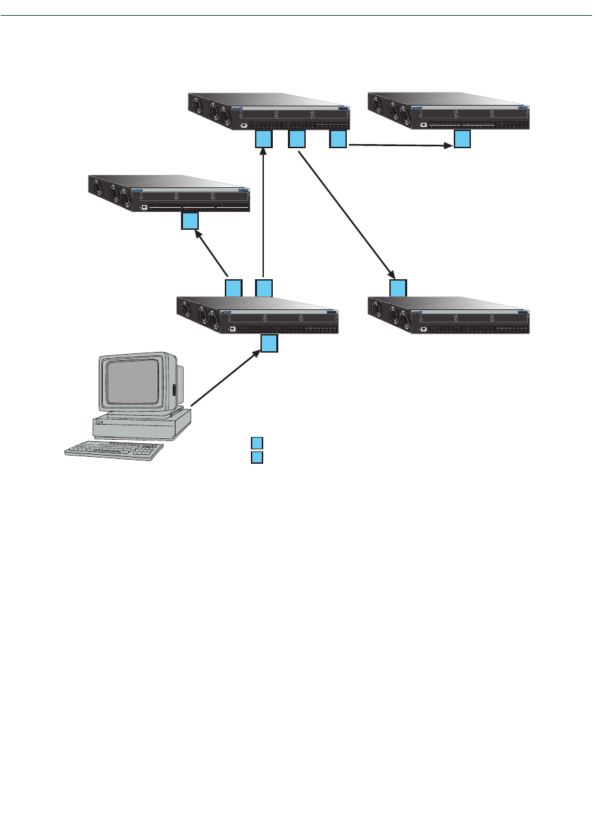
VLAN Configuration Command Set
Enabling/Disabling GVRP
7-34 Matrix NSA Series Configuration Guide
Figure 7-1 Example of VLAN Propagation via GVRP
Configuring a VLAN on an 802.1Q switch creates a static VLAN entry. The entry will always
remain registered and will not time out. However, dynamic entries will time-out and their
registrations will be removed from the member list if the end station A is removed. This ensures
that, if switches are disconnected or if end stations are removed, the registered information remains
accurate.
The end result is that the port egress list of a port is updated with information about VLANs that
reside on that port, even if the actual station on the VLAN is several hops away.
End
Station A
Switch 4 Switch 5
= Port registered as a member of VLAN Blue
= Port declaring VLAN Blue
D
R
3680_77
1
1
23D
R
D
Switch 1
1R
R
3
Switch 2
12
D
RD
2
1
46810 12 14 16
3579 11 13 15
18
17
20 22 24 26 28 30 32
19 21 23 25 27 29 31
34
33
36 38 40 42 44 46 48
35 37 39 41 43 45 47
Reset
Console PWR
CPU
1H152-51
Switch 3
1R
2
1
46810 12 14 16
3579 11 13 15
18
17
20 22 24 26 28 30 32
19 21 23 25 27 29 31
34
33
36 38 40 42 44 46 48
35 37 39 41 43 45 47
Reset
Reset
Console PWR
CPU
1H152-51
2
1
46810 12 14 16
3579 11 13 15
18
17
20 22 24 26 28 30 32
19 21 23 25 27 29 31
34
33
36 38 40 42 44 46 48
35 37 39 41 43 45 47
Reset
Console
Console PWR
CPU
1H152-51
2
1
46810 12 14 16
3579 11 13 15
18
17
20 22 24 26 28 30 32
19 21 23 25 27 29 31
34
33
36 38 40 42 44 46 48
35 37 39 41 43 45 47
Reset
Console PWR
CPU
1H152-51
2
1
46810 12 14 16
3579 11 13 15
18
17
20 22 24 26 28 30 32
19 21 23 25 27 29 31
34
33
36 38 40 42 44 46 48
35 37 39 41 43 45 47
Reset
Console
Console PWR
CPU
1H152-51

VLAN Configuration Command Set
Enabling/Disabling GVRP
Matrix NSA Series Configuration Guide 7-35
Commands
The commands used to configure GVRP are listed below and described in the associated section as
shown.
•show gvrp (Section 7.3.6.1)
•show garp timer (Section 7.3.6.2)
•set gvrp (Section 7.3.6.3)
•clear gvrp (Section 7.3.6.4)
•set garp timer (Section 7.3.6.5)
•clear garp timer (Section 7.3.6.6)

VLAN Configuration Command Set
Enabling/Disabling GVRP
7-36 Matrix NSA Series Configuration Guide
7.3.6.1 show gvrp
Use this command to display GVRP configuration information.
show gvrp [port-string]
Syntax Description
Command Defaults
If port-string is not specified, GVRP configuration information will be displayed
for all ports and the device.
Command Type
Switch command.
Command Mode
Read-Only.
Example
This example shows how to display GVRP status for the device and for Fast Ethernet port 1 in port
group 2:
Table 7-4 provides an explanation of the command output.
port-string (Optional) Displays GVRP configuration information for
specific port(s). For a detailed description of possible
port-string values, refer to Section 4.1.1.
Matrix(rw)->show gvrp fe.2.1
Global GVRP status is enabled.
Port Number GVRP status Last PDU Origin
----------- ----------- -----------------
fe.2.1 enabled 00-e0-63-97-d4-36
Table 7-4 show gvrp Output Details
Output What It Displays...
Port Number Port designation. For a detailed description of possible
port-string values, refer to Section 4.1.1.

VLAN Configuration Command Set
Enabling/Disabling GVRP
Matrix NSA Series Configuration Guide 7-37
GVRP status Whether GVRP is enabled or disabled on the port.
Last PDU Origin MAC address of the last GVRP frame received on the port.
Table 7-4 show gvrp Output Details (Continued)
Output What It Displays...

VLAN Configuration Command Set
Enabling/Disabling GVRP
7-38 Matrix NSA Series Configuration Guide
7.3.6.2 show garp timer
Use this command to display GARP timer values for one or more ports.
show garp timer [port-string]
Syntax Description
Command Defaults
If port-string is not specified, GARP timer information will be displayed for all
ports.
Command Type
Switch command.
Command Mode
Read-Only.
Example
This example shows how to display GARP timer information on Fast Ethernet ports 1 through 10
in port group 1:
port-string (Optional) Displays GARP timer information for specific
port(s). For a detailed description of possible port-string
values, refer to Section 4.1.1.
NOTE: For a functional description of the terms join, leave, and leaveall timers, refer
to the standard IEEE 802.1Q documentation, which is not supplied with this device.

VLAN Configuration Command Set
Enabling/Disabling GVRP
Matrix NSA Series Configuration Guide 7-39
Table 7-5 provides an explanation of the command output. For details on using the
set gvrp command to enable or disable GVRP, refer to Section 7.3.6.3. For details
on using the set garp timer command to change default timer values, refer to
Section 7.3.6.5.
Matrix(rw)->show garp timer fe.1.1-10
Port based GARP Configuration: (Timer units are centiseconds)
Port Number Join Leave Leaveall
----------- ---------- ---------- ----------
fe.1.1 20 60 1000
fe.1.2 20 60 1000
fe.1.3 20 60 1000
fe.1.4 20 60 1000
fe.1.5 20 60 1000
fe.1.6 20 60 1000
fe.1.7 20 60 1000
fe.1.8 20 60 1000
fe.1.9 20 60 1000
fe.1.10 20 60 1000
Table 7-5 show gvrp configuration Output Details
Output What It Displays...
Port Number Port designation. For a detailed description of possible
port-string values, refer to Section 4.1.1.
Join Join timer setting.
Leave Leave timer setting.
Leaveall Leavall timer setting.

VLAN Configuration Command Set
Enabling/Disabling GVRP
7-40 Matrix NSA Series Configuration Guide
7.3.6.3 set gvrp
Use this command to enable or disable GVRP globally on the device or on one or more ports.
set gvrp {enable | disable} [port-string]
Syntax Description
Command Defaults
If port-string is not specified, GVRP will be disabled or enabled for all ports.
Command Type
Switch command.
Command Mode
Read-Write.
Examples
This example shows how to enable GVRP globally on the device:
This example shows how to disable GVRP globally on the device:
This example shows how to enable GVRP on Fast Ethernet port 3 in port group 1:
disable | enable Disables or enables GVRP on the device.
port-string (Optional) Disables or enables GVRP on specific port(s). For
a detailed description of possible port-string values, refer to
Section 4.1.1.
Matrix(rw)->set gvrp enable
Matrix(rw)->set gvrp disable
Matrix(rw)->set gvrp enable fe.1.3

VLAN Configuration Command Set
Enabling/Disabling GVRP
Matrix NSA Series Configuration Guide 7-41
7.3.6.4 clear gvrp
Use this command to clear GVRP status or on one or more ports.
clear gvrp [port-string]
Syntax Description
Command Defaults
If port-string is not specified, GVRP status will be cleared for all ports.
Command Type
Switch command.
Command Mode
Read-Write.
Examples
This example shows how to clear GVRP status globally on the device:
port-string (Optional) Clears GVRP status on specific port(s). For a
detailed description of possible port-string values, refer to
Section 4.1.1.
Matrix(rw)->clear gvrp

VLAN Configuration Command Set
Enabling/Disabling GVRP
7-42 Matrix NSA Series Configuration Guide
7.3.6.5 set garp timer
Use this command to adjust the values of the join, leave, and leaveall timers.
set garp timer {[join timer-value] [leave timer-value] [leaveall timer-value]}
port-string
Syntax Description
Command Defaults
None.
Command Type
Switch command.
Command Mode
Read-Write.
Examples
This example shows how to set the GARP join timer value to 100 centiseconds for all ports:
This example shows how to set the leave timer value to 300 centiseconds for all ports:
NOTE: The setting of these timers is critical and should only be changed by personnel
familiar with the 802.1Q standards documentation, which is not supplied with this
device.
join timer-value Sets the GARP join timer in centiseconds (Refer to 802.1Q
standard.)
leave timer-value Sets the GARP leave timer in centiseconds (Refer to
802.1Q standard.)
leaveall
timer-value Sets the GARP leaveall timer in centiseconds (Refer to
802.1Q standard.)
port-string Specifies the port(s) on which to configure GARP timer
settings. For a detailed description of possible port-string
values, refer to Section 4.1.1.
Matrix(rw)->set garp timer join 100 *.*.*
Matrix(rw)->set garp timer leave 300 *.*.*

VLAN Configuration Command Set
Enabling/Disabling GVRP
Matrix NSA Series Configuration Guide 7-43
This example shows how to set the leaveall timer value to 20000 centiseconds for all ports:
Matrix(rw)->set garp timer leaveall 20000 *.*.*

VLAN Configuration Command Set
Enabling/Disabling GVRP
7-44 Matrix NSA Series Configuration Guide
7.3.6.6 clear garp timer
Use this command to reset GARP timers back to default values.
clear garp timer {[join] [leave] [leaveall]} port-string
Syntax Description
Command Defaults
At least one optional parameter must be entered.
Command Type
Switch command.
Command Mode
Read-Write.
Example
This example shows how to reset the GARP leave timer to 60 centiseconds on Fast Ethernet port 5
in port group 2:
join (Optional) Resets the join timer to 20 centiseconds.
leave (Optional) Resets the leave timer to 60 centiseconds.
leaveall (Optional) Resets the leaveall timer to 1000 centiseconds.
port-string Specifies the port(s) on which to reset GARP timer(s). For a
detailed description of possible port-string values, refer to
Section 4.1.1.
Matrix(rw)->clear garp timer leave fe.2.5

Matrix NSA Series Configuration Guide 8-1
8
Policy Classification Configuration
This chapter describes the Policy Classification set of commands and how to use them.
8.1 POLICY CLASSIFICATION CONFIGURATION SUMMARY
Matrix Series devices support policy profile-based provisioning of network resources by allowing
IT administrators to:
•Create, change or remove user profiles based on business-specific use of network services.
•Permit or deny access to specific services by creating and assigning classification rules which
map user profiles to protocol-based frame filtering policies configured for a particular VLAN or
Class of Service (CoS).
•Assign or unassign ports to policy profiles so that only ports activated for a profile will be
allowed to transmit frames accordingly.
•Configure CoS to automatically assign policy-based inbound rate limiters and transmit queues.
•Set the status of dynamically assigned policy profiles.
NOTE: It is recommended that you use Enterasys Networks NetSight Atlas Policy
Manager as an alternative to CLI for configuring policy classification on the Matrix
Series devices.
NOTE: Matrix Series devices also support policy-based routing, which forwards or
drops packets at Layer 3 according to matching access lists (ACLs) in route maps
configured on routing interfaces. For details, refer to Section 14.3.13.

Process Overview: Policy Classification Configuration
Configuring Policy Profiles
8-2 Matrix NSA Series Configuration Guide
8.2 PROCESS OVERVIEW: POLICY CLASSIFICATION
CONFIGURATION
Use the following steps as a guide to configure policy classification on the device:
1. Configuring policy profiles (Section 8.3.1)
2. Assigning classification rules to policy profiles (Section 8.3.2)
3. Configuring policy-based Class of Service (CoS) (Section 8.3.3)
4. Setting the status of dynamically assigned policy profiles (Section )
8.3 POLICY CLASSIFICATION CONFIGURATION COMMAND SET
8.3.1 Configuring Policy Profiles
Purpose
To review, create, change and remove policy profiles for managing network resources.
Commands
The commands used to review and configure policy profiles are listed below and described in the
associated section as shown.
•show policy profile (Section 8.3.1.1)
•set policy profile (Section 8.3.1.2)
•clear policy profile (Section 8.3.1.3)
•show policy invalid (Section 8.3.1.4)
•set policy invalid action (Section 8.3.1.5)
•clear policy invalid action (Section 8.3.1.6)
•show port tci overwrite (Section 8.3.1.7)
•set port tci overwrite (Section 8.3.1.7)
•show policy accounting (Section 8.3.1.8)
•set policy accounting (Section 8.3.1.9)
•clear policy accounting (Section 8.3.1.10)

Policy Classification Configuration Command Set
Configuring Policy Profiles
Matrix NSA Series Configuration Guide 8-3
•show policy syslog (Section 8.3.1.11)
•set policy syslog (Section 8.3.1.12)
•clear policy syslog (Section 8.3.1.13)
•set policy maptable (Section 8.3.1.14)
•show policy maptable (Section 8.3.1.15)
•clear policy maptable (Section 8.3.1.16)

Policy Classification Configuration Command Set
Configuring Policy Profiles
8-4 Matrix NSA Series Configuration Guide
8.3.1.1 show policy profile
Use this command to display policy profile information.
show policy profile {all | profile-index [consecutive-pids] [-verbose]}
Syntax Description
Command Defaults
If optional parameters are not specified, summary information will be displayed for
the specified index or all indexes.
Command Type
Switch command.
Command Mode
Read-Only.
Example
This example shows how to display policy information for policy profile 11:
all | profile-index Displays policy information for all profile indexes or a
specific profile index.
consecutive-pids (Optional) Displays information for specified consecutive
profile indexes.
-verbose (Optional) Displays detailed information.
Matrix(rw)->show policy profile 11
Profile Index :11
Profile Name :MacAuth1
Row Status :active
Port VID Status :enabled
Port VID Override :11
CoS Status :disabled
CoS :0
Tagged Egress VLAN List :11
Forbidden VLAN List :none
Untagged VLAN List :none
Replace TCI Status :enabled
Admin Profile Usage :none
Oper Profile Usage :fe.2.1-2
Dynamic Profile Usage :fe.2.1-2

Policy Classification Configuration Command Set
Configuring Policy Profiles
Matrix NSA Series Configuration Guide 8-5
Table 8-1 provides an explanation of the command output.
Table 8-1 show policy profile Output Details
Output What It Displays...
Profile Index Number of the prolicy profile.
Profile Name User-supplied name assigned to this policy profile.
Row Status Whether or not the policy profile is enabled (active) or
disabled.
Port VID Status Whether or not PVID override is enabled or disabled for
this policy profile. If all the classification rules associated
with this profile are missed, then this parameter, if
specified, determines default behavior.
Port VID Override The PVID to assign to packets, if PVID override is enabled.
CoS Status Whether or not Class of Service override is enabled or
disabled for this profile. If all the classification rules
associated with this profile are missed, then this parameter,
if specified, determines default behavior.
CoS The CoS priority value to assign to packets, if CoS
override is enabled.
Tagged Egress
VLAN List VLAN(s) that ports to which the policy profile is assigned
can use for tagged egress.
Forbidden VLAN
List VLAN(s) forbidden to ports to which the policy profile is
assigned.
Untagged VLAN
List VLAN(s) that ports to which the policy profile is assigned
can use for untagged egress.
Replace TCI
status Whether or not the TCI overwrite function is enabled or
disabled for this profile.
Admin Profile
Usage Ports administratively assigned to use this policy profile.
Oper Profile
Usage Ports currently assigned to use this policy profile.
Dynamic Profile
Usage Port dynamically assigned to use this policy profile.

Policy Classification Configuration Command Set
Configuring Policy Profiles
8-6 Matrix NSA Series Configuration Guide
8.3.1.2 set policy profile
Use this command to create a policy profile entry.
set policy profile profile-index [name name] [pvid-status {enable | disable}]
[pvid pvid] [cos-status {enable | disable}] [cos cos] [egress-vlans egress-vlans]
[forbidden-vlans forbidden-vlans] [untagged-vlans untagged-vlans] [append]
[clear]
Syntax Description
profile-index Specifies an index number for the policy profile. Valid
values are 1 - 1023.
name name (Optional) Specifies a name for the policy profile. This is a
string from 1 to 64 characters.
pvid-status
enable | disable (Optional) Enables or disables PVID override for this
policy profile. If all the classification rules associated with
this profile are missed, then this parameter, if specified,
determines default behavior.
pvid pvid (Optional) Specifies the PVID to assign to packets, if PVID
override is enabled and invoked as the default behavior.
cos-status enable
| disable (Optional) Enables or disables Class of Service override for
this policy profile. If all the classification rules associated
with this profile are missed, then this parameter, if
specified, determines default behavior.
cos cos (Optional) Specifies a COS value to assign to packets, if
CoS override is enabled and invoked as the default
behavior. Valid values are 0 to 255.
egress-vlans
egress-vlans (Optional) Specifies that the port to which this policy
profile is applied should be added to the egress list of the
VLANs defined by egress-vlans. Packets will be formatted
as tagged.
forbidden-vlans
forbidden-vlans (Optional) Specifies that the port to which this policy
profile is applied should be added as forbidden to the egress
list of the VLANs defined by forbidden-vlans. Packets from
this port will not be allowed to participate in the listed
VLANs.

Policy Classification Configuration Command Set
Configuring Policy Profiles
Matrix NSA Series Configuration Guide 8-7
Command Defaults
If optional parameters are not specified, none will be applied.
Command Type
Switch command.
Command Mode
Read-Write.
Example
This example shows how to create a policy profile 1 named “netadmin” with PVID override enabled
for PVID 10, and Class-of-Service override enabled for CoS 5. This profile can use VLAN 10 for
untagged egress:
untagged-vlans
untagged-vlans (Optional) Specifies that the port to which this policy
profile is applied should be added to the egress list of the
VLANs defined by untagged-vlans. Packets will be
formatted as untagged.
append (Optional) Appends this policy profile setting to settings
previously specified for this policy profile by the
egress-vlans, forbidden-vlans, or untagged-vlans
parameters.
If append is not used, previous VLAN settings are replaced.
clear (Optional) Clears this policy profile setting from settings
previously specified for this policy profile by the
egress-vlans, forbidden-vlans, or untagged-vlans
parameters.
Matrix(rw)->set policy profile 1 name netadmin pvid-status enable pvid 10
cos-status enable cos 5 untagged-vlans 10

Policy Classification Configuration Command Set
Configuring Policy Profiles
8-8 Matrix NSA Series Configuration Guide
8.3.1.3 clear policy profile
Use this command to delete a policy profile entry.
clear policy profile profile-index
Syntax Description
Command Defaults
None.
Command Type
Switch command.
Command Mode
Read-Write.
Example
This example shows how to delete policy profile 8:
profile-index Specifies the index number of the policy profile entry to be
deleted. Valid values are 1 to 1023.
Matrix(rw)->clear policy profile 8

Policy Classification Configuration Command Set
Configuring Policy Profiles
Matrix NSA Series Configuration Guide 8-9
8.3.1.4 show policy invalid
Displays information about the action the device will apply on an invalid or unknown policy.
show policy invalid {action | count | all}
Syntax Description
Command Defaults
None.
Command Type
Switch command.
Command Mode
Read-Only.
Example
This example shows how to display invalid policy action and count information:
action | count | all Shows the action the device should take if asked to apply an
invalid or unknown policy, or the number of times the
device has detected an invalid/unknown policy, or both
action and count information.
Matrix(rw)->show policy invalid all
Current action on invalid/unknown profile is: Forward packets
Number of invalid/unknown profiles detected: 4

Policy Classification Configuration Command Set
Configuring Policy Profiles
8-10 Matrix NSA Series Configuration Guide
8.3.1.5 set policy invalid action
Use this command to assign the action the device will apply to an invalid or unknown policy.
set policy invalid action {default-policy | drop | forward}
Syntax Description
Command Defaults
None.
Command Type
Switch command.
Command Mode
Read-Write.
Example
This example shows how to assign a drop action to invalid policies:
default-policy Instructs the device to ignore this result and search for the
next policy assignment rule.
drop Instructs the device to block traffic.
forward Instructs the device to forward traffic as if no policy has
been assigned.
Matrix(rw)->set policy invalid action drop

Policy Classification Configuration Command Set
Configuring Policy Profiles
Matrix NSA Series Configuration Guide 8-11
8.3.1.6 clear policy invalid action
Use this command to reset the action the device will apply to an invalid or unknown policy to the
default action of applying the default policy.
clear policy invalid action
Syntax Description
None.
Command Defaults
None.
Command Type
Switch command.
Command Mode
Read-Write.
Example
This example shows how to reset the invalid policy action:
Matrix(rw)->clear policy invalid action

Policy Classification Configuration Command Set
Configuring Policy Profiles
8-12 Matrix NSA Series Configuration Guide
8.3.1.7 set port tci overwrite
Use this command to enable or disable the TCI overwrite function on one or more ports. When
enabled, this allows policy rules to overwrite user priority and other classification information in
the VLAN tag’s TCI field. It will also overwrite ingressing frames tagged to a port VLAN and
policy assignment, if a policy has not already been assigned.
set port tcioverwrite port-string {enable | disable}
Syntax Description
Command Defaults
None.
Command Type
Switch command.
Command Mode
Read-Write.
Example
This example shows how to enable TCI overwrite on port fe.1.3:
port-string Specifies port(s) on which to enable or disable the TCI
overwrite function.
enable | disable Enables or disables the TCI overwrite function.
Matrix(rw)->set port tcioverwrite fe.1.3 enable

Policy Classification Configuration Command Set
Configuring Policy Profiles
Matrix NSA Series Configuration Guide 8-13
8.3.1.8 show policy accounting
Use this command to display the status of policy accounting.
show policy accounting
Syntax Description
None.
Command Defaults
None.
Command Type
Switch command.
Command Mode
Read-Only.
Example
This example shows how to display the status of policy accounting:
Matrix(rw)->show policy accounting
Accounting Enable control status is ENABLED

Policy Classification Configuration Command Set
Configuring Policy Profiles
8-14 Matrix NSA Series Configuration Guide
8.3.1.9 set policy accounting
Use this command to enable or disable policy accounting, which controls the collection of
classification rule statistics. This function is enabled by default.
set policy accounting {enable | disable}
Syntax Description
Command Defaults
None.
Command Type
Switch command.
Command Mode
Read-Write.
Example
This example shows how to disable policy accounting:
enable | disable Enables or disables the policy accounting function.
Matrix(rw)->set policy accounting disable

Policy Classification Configuration Command Set
Configuring Policy Profiles
Matrix NSA Series Configuration Guide 8-15
8.3.1.10 clear policy accounting
Use this command to restore policy accounting to its default state of enabled.
clear policy accounting
Syntax Description
None.
Command Defaults
None.
Command Type
Switch command.
Command Mode
Read-Write.
Example
This example shows how to re-enable policy accounting:
Matrix(rw)->clear policy accounting

Policy Classification Configuration Command Set
Configuring Policy Profiles
8-16 Matrix NSA Series Configuration Guide
8.3.1.11 show policy syslog
Use this command to show the formatting of rule usage messages. The messages will be either
machine-readable or human-readable.
show policy syslog machine-readable
Syntax Description
Command Defaults
None.
Command Type
Switch command.
Command Mode
Read-Only.
Example
This example shows how to display the device formatting of rule usage messages:
machine-readable Show the control for device formatting of rule usage
messages. The format is either machine readable or
human readable.
Matrix(rw)->show policy syslog machine-readable
Syslog machine-readable: disabled

Policy Classification Configuration Command Set
Configuring Policy Profiles
Matrix NSA Series Configuration Guide 8-17
8.3.1.12 set policy syslog
Use this command to set the rule usage messages as either machine-readable or human-readable.
set policy syslog machine-readable {enable | disable}
Syntax Description
Command Defaults
None.
Command Type
Switch command.
Command Mode
Read-Write.
Example
This example shows how to set the device formatting of rule usage messages as machine-readable:
machine-readable Set the formatting of rule usage messages. The format is
either machine-readable or human-readable.
enable | disable enable - Formats the rule usage messages so that they
might be processed by a machine (scripting backend, etc.)
disable - Formats the rule usage messages for human
consumption
Matrix(rw)->set policy syslog machine-readable enable

Policy Classification Configuration Command Set
Configuring Policy Profiles
8-18 Matrix NSA Series Configuration Guide
8.3.1.13 clear policy syslog
Use this command to clear the rule usage messages to the default state of disabled
(human-readable).
clear policy syslog machine-readable
Syntax Description
Command Defaults
None.
Command Type
Switch command.
Command Mode
Read-Write.
Example
This example shows how to clear the machine-readable formatting of rule usage messages to the
default setting of human-readable:
machine-readable Clear the machine-readable formatting of rule usage
messages to its default which is human-readable
(disabled).
Matrix(rw)->clear policy syslog machine-readable

Policy Classification Configuration Command Set
Configuring Policy Profiles
Matrix NSA Series Configuration Guide 8-19
8.3.1.14 set policy maptable
Use this command to set the Set VLAN ID - Policy Profile mappings table.
set policy maptable {vlan-list profile-index | response {tunnel | policy | both}}
Syntax Description
Command Defaults
None.
Command Type
Switch command.
Command Mode
Read-Write.
Example
This example shows how to set the Policy Profile mappings table for VLAN 3 and for Policy ID 8:
This example shows how to use both tunnel and policy attributes in the RADIUS response for the
Policy Profile mappings .
vlan-list VLAN ID or range of IDs (1 to 4094)
profile-index Policy ID (1 to 1023)
response tunnel |
policy | both Indicates which attributes to use from RADIUS response.
tunnel - Apply the vlan-tunnel attribute
policy - Apply the filter-id attribute
both - Apply both attributes
Matrix(rw)->set policy maptable 3 8
Matrix(rw)->set policy maptable response both

Policy Classification Configuration Command Set
Configuring Policy Profiles
8-20 Matrix NSA Series Configuration Guide
8.3.1.15 show policy maptable
Use this command to display the VLAN ID - Policy Profile mappings table.
show policy maptable vlan-list
Syntax Description
Command Defaults
None.
Command Type
Switch command.
Command Mode
Read.
Example
This example shows the Policy Profile mappings table for all configured VLANs
vlan-list VLAN ID or range of IDs (1 to 4094)
Matrix(rw)->show policy maptable
Policy map response: policy
Policy map last change: 0 days 0:00:00:00
Policy Mappings :
VLAN ID Policy Profile
1 22 (Engineering User)
2 23 (Sales User)
4094 400 (Guest)

Policy Classification Configuration Command Set
Configuring Policy Profiles
Matrix NSA Series Configuration Guide 8-21
8.3.1.16 clear policy maptable
Use this command to clear the VLAN ID - Policy Profile mappings table.
clear policy maptable vlan-list | response
Syntax Description
Command Defaults
None.
Command Type
Switch command.
Command Mode
Read-Write.
Example
This example clears the Policy Profile mappings table.
vlan-list VLAN ID or range of IDs (1 to 4094)
response Applied the filter-id attribute
Matrix(rw)->clear policy maptable response

Policy Classification Configuration Command Set
Assigning Classification Rules to Policy Profiles
8-22 Matrix NSA Series Configuration Guide
8.3.2 Assigning Classification Rules to Policy Profiles
Purpose
To review, assign and unassign classification and admin rules. Classification rules map policy
profiles to protocol-based frame filtering policies configured for a particular VLAN or Class of
Service (CoS). Admin rules assign policy profiles to incoming traffic.
Commands
The commands used to review, assign and unassign classification rules to policy profiles and ports
are listed below and described in the associated section as shown.
•show policy rule (Section 8.3.2.1)
•show policy capability (Section 8.3.2.2)
•set policy classify
•set policy rule (Section 8.3.2.4)
•clear policy rule (Section 8.3.2.5)
•clear policy all-rules (Section 8.3.2.6)
•set policy port (Section 8.3.2.7)
•show policy allowed-type (Section 8.3.2.8)
•set policy allowed-type (Section 8.3.2.9)
•clear policy allowed-type (Section 8.3.2.10)
•clear policy port-hit (Section 8.3.2.11)

Policy Classification Configuration Command Set
Assigning Classification Rules to Policy Profiles
Matrix NSA Series Configuration Guide 8-23
8.3.2.1 show policy rule
Use this command to display policy classification and admin rule information.
show policy rule [attribute] | [all] | [admin-profile] | [profile-index] [ether |
ipdest | ipfrag | ipproto | ipsource | iptos | llcDsapSsap | macdest | macsource |
port | tcpdestport| tcpsourceport| udpdestport | udpsourceport [data] [mask
mask] [port-string port-string] [rule-status {active | not-in-service |
not-ready}] [storage-type {non-volatile | volatile}] [vlan vlan] | [drop |
forward] [dynamic-pid dynamic-pid] [cos cos] [admin-pid admin-pid]
[-verbose]
Syntax Description
attribute Displays the attributes of the specified rules.
all |
admin-profile |
profile-index
Displays all admin and classification rules, rules for the
admin profile, or for a specific profile-index number. Valid
index values are 1 - 1023.
ether Displays Ethernet type II rules.
ipdest Displays IP destination address rules.
ipfrag Displays IP fragmentation rules.
ipproto Displays IP protocol field in IP packet rules.
ipsource Displays IP source address rules.
iptos Displays Type of Service rules.
llcDsapSsap Displays 802.3 DSAP/SSAP rules.
macdest Displays MAC destination address rules.
macsource Displays MAC source address rules.
port Displays port related rules.
tcpdestport Displays TCP destination port rules.
tcpsourceport Displays TCP source port rules.
udpdestport Displays UDP destination port rules.
udpsourceport Displays UDP source port rules.

Policy Classification Configuration Command Set
Assigning Classification Rules to Policy Profiles
8-24 Matrix NSA Series Configuration Guide
Command Defaults
•If port-string, rule status, storage type, Syslog state, trap, and usage-list are not
specified, all rules related to other specifications will be displayed.
•If verbose is not specified, summary information will be displayed.
Command Type
Switch command.
Command Mode
Read-Only.
data (Not required for ipfrag classification.) Displays rules for a
predefined classifier. This value is dependent on the
classification type entered. Refer to Table 8-3 for valid
values for each classification type.
mask mask (Optional) Displays rules for a specific data mask. Refer to
Table 8-3 for valid values for each classification type and
data value.
port-string
port-string (Optional) Displays rules related to a specific ingress port.
rule-status active
| not-in-service |
not-ready
(Optional) Displays rules related to a specific rules status.
storage-type
non-volatile |
volatile
(Optional) Displays rules configured for either non-volatile
or volatile storage.
vlan vlan (Optional) Displays rules for a specific VLAN ID.
drop | forward Displays rules based on whether matching packets specified
by the vlan parameter will be dropped or forwarded.
dynamic-pid
dynamic-pid Displays rules associated with a specific dynamic policy
profile index ID.
cos cos (Optional) Displays rules for a Class-of-Service value.
admin-pid
admin-pid Displays rules associated with a specific administrative
policy profile index ID.
-verbose (Optional) Displays detailed information.

Policy Classification Configuration Command Set
Assigning Classification Rules to Policy Profiles
Matrix NSA Series Configuration Guide 8-25
Examples
This example shows how to display policy classification information for Ethernet type 2 rules:
This example shows how to display admin rule information for the policy profile with index
number 1:
Table 8-2 provides an explanation of the command output.
Matrix(rw)->show policy rule ether
|PID |Rule Type |Rule Data |Mk|PortStr |RS|ST|S|T|D|VLAN|CoS |U|
| 1 |Ether |32923 (0x809B) |16|All | A|NV|Y|Y| | 105| |?|
| 1 |Ether |33011 (0x80F3) |16|All | A|NV|Y|Y| | 105| |?|
| 1 |Ether |33079 (0x8137) |16|All | A|NV|Y|Y| | 101| |?|
| 1 |Ether |33080 (0x8138) |16|All | A|NV|Y|Y| | 101| |?|
| 1 |Ether |33276 (0x81FC) |16|All | A|NV|Y|Y| |drop| |?|
| 2 |Ether |32923 (0x809B) |16|All | A|NV|Y|Y| | 105| |?|
| 2 |Ether |33011 (0x80F3) |16|All | A|NV|Y|Y| | 105| |?|
| 2 |Ether |33079 (0x8137) |16|All | A|NV|Y|Y| | 101| |?|
Matrix(rw)->show policy rule admin-pid 1
|Admin|Rule Type |Rule Data |Mk|PortStr |RS|ST|S|T|D|dPID|aPID|U|
|admin|Port |fe.1.1 |16|fe.1.1 | A|NV| | | | | 1|?|
|admin|Port |fe.1.2 |16|fe.1.2 | A|NV| | | | | 1|?|
|admin|Port |fe.1.3 |16|fe.1.3 | A|NV| | | | | 1|?|
|admin|Port |fe.1.4 |16|fe.1.4 | A|NV| | | | | 1|?|
|admin|Port |fe.1.5 |16|fe.1.5 | A|NV| | | | | 1|?|
|admin|Port |fe.1.6 |16|fe.1.6 | A|NV| | | | | 1|?|
Table 8-2 show policy rule Output Details
Output What It Displays...
PID Profile profile index number, indicating a classification rule
is displayed. Assigned to this classification rule with the set
policy profile command (Section 8.3.1.2).
Admin Indicates an admin rule is displayed.
Rule Type Whether the rule protocol-based or port-based. Refer to
Table 8-3 for valid classification types.
Rule Data Rule data value. Refer to Table 8-3 for valid values for each
classification type.
Mk Rule data mask. Refer to Table 8-3 for valid values for each
classification data value.

Policy Classification Configuration Command Set
Assigning Classification Rules to Policy Profiles
8-26 Matrix NSA Series Configuration Guide
PortStr Ingress port(s) to which this rule applies.
RS Whether or not the status of this rule is active (A), not in
service or not ready.
ST Whether or not this rule’s storage type is non-volatile (NV)
or volatile (V).
Vlan VLAN ID to which this rule applies and whether or not
matching packets will be dropped or forwarded.
CoS Class of Service value to which this rule applies.
dPID Whether or not this is a dynamic profile ID.
aPID Whether or not this is an administrative profile index ID.
Table 8-2 show policy rule Output Details (Continued)
Output What It Displays...

Policy Classification Configuration Command Set
Assigning Classification Rules to Policy Profiles
Matrix NSA Series Configuration Guide 8-27
8.3.2.2 show policy capability
Use this command to display all policy classification capabilities supported by your Matrix Series
device. The output of this command shows a table listing classifiable traffic attributes and the type
of actions, by rule type, that can be executed relative to each attribute. Above the table is a list of
all the actions possible on this device.
The left-most column of the table lists all possible classifiable traffic attributes. The next two
columns from the left indicate how policy profiles may be assigned, either administratively or
dynamically. The next four columns from the left indicate the actions that may be performed. The
last three columns indicate auditing options.
An x in an action column for a traffic attribute row indicates that your system has the capability to
perform that action for traffic classified by that attribute.
show policy capability
Syntax Description
None.
Command Defaults
None.
Command Type
Switch command.
Command Mode
Read-Only.
Example
This example shows how to display your Matrix Series device’s policy classification capabilities.
In this case, Matrix DFE-Platinum Series capabilities are shown. Refer to Section 8.3.2.4 for a
description of the parameters displayed:

Policy Classification Configuration Command Set
Assigning Classification Rules to Policy Profiles
8-28 Matrix NSA Series Configuration Guide
Matrix(rw)->show policy capability
The following supports related to policy are supported in this device:
VLAN Forwarding Priority Permit
Deny TCI Overwrite Rule-Use Notification
Rules Table Rule-Use Accounting
Longest Prefix Rules Port Disable Action
=============================================================
| | D | | | | | F | | | D |
| | Y | | | | | O | S | | I |
| | N | A | | | | R | Y | | S |
| | A | D | V | | D | W | S | T | A |
| | M | M | L | C | R | A | L | R | B |
| | I | I | A | O | O | R | O | A | L |
| SUPPORTED RULE TYPES | C | N | N | S | P | D | G | P | E |
=============================================================
|MAC source address | X | X | X | X | X | X | X | X | X |
|MAC destination address | X | X | X | X | X | X | X | X | X |
|IPX source address | X | X | X | X | X | X | X | X | X |
|IPX destination address | X | X | X | X | X | X | X | X | X |
|IPX source socket | X | X | X | X | X | X | X | X | X |
|IPX destination socket | X | X | X | X | X | X | X | X | X |
|IPX transmission control | X | X | X | X | X | X | X | X | X |
|IPX type field | X | X | X | X | X | X | X | X | X |
|IPv6 source address | | | | | | | | | |
|IPv6 destination address | | | | | | | | | |
|IPv6 flow label | | | | | | | | | |
|IP source address | X | X | X | X | X | X | X | X | X |
|IP destination address | X | X | X | X | X | X | X | X | X |
|IP fragmentation | X | X | X | X | X | X | X | X | X |
|UDP port source | X | X | X | X | X | X | X | X | X |
|UDP port destination | X | X | X | X | X | X | X | X | X |
|TCP port source | X | X | X | X | X | X | X | X | X |
|TCP port destination | X | X | X | X | X | X | X | X | X |
|ICMP packet type | X | X | X | X | X | X | X | X | X |
|TTL | | | | | | | | | |
|IP type of service | X | X | X | X | X | X | X | X | X |
|IP proto | X | X | X | X | X | X | X | X | X |
|Ether II packet type | X | X | X | X | X | X | X | X | X |
|LLC DSAP/SSAP/CTRL | X | X | X | X | X | X | X | X | X |
|VLAN tag | X | X | X | X | X | X | X | X | X |
|Replace tci | X | X | X | X | X | X | X | X | X |
|Port string | X | X | X | X | X | X | X | X | X |
============================================================

Policy Classification Configuration Command Set
Assigning Classification Rules to Policy Profiles
Matrix NSA Series Configuration Guide 8-29
8.3.2.3 set policy classify
Use this command to assign incoming untagged frames to a specific policy profile, classification
and to VLAN or Class-of-Service classification rules.
set policy classify profile-index classify-index {vlan | cos} {classify-value |
forward | drop} {ether | llc | iptos | ipproto | ipxclass | ipxtype | ipsource | ipdest
| ipxsource | ipxdest | udpportsource | udpportdest | tcpportsource | tcpportdest
| ipxsourcesocket | ipxdestsocket | macsource | macdest | ipfrag | icmptype |
vlantag | tci | port} [class-data-val] [class-data-mask]
Syntax Description
NOTE: Classification rules are automatically enabled when created.
profile-index Specifies that this is an administrative rule or associates
this classification rule with a policy profile index
configured with the set policy profile command
(Section 8.3.1.2). Valid profile-index values are 1- 1023.
classify-index Policy Classification Index (1-65535)
vlan Specifies Vlan Classification Rule
cos Specifies Class Of Service Classification Rule
classify-value vlan / Class Of Service (0-4095)
forward Specifies Forwarding of packet
drop Specifies Dropping of packet
ether Classifies based on type field in Ethernet II packet.
llc DSAP/SSAP pair in 802.3 type packet field - (0 - 65535)
iptos Classifies based on Type of Service field in IP packet.
ipproto Classifies based on protocol field in IP packet.
ipsource Classifies based on source IP address
ipdest Classifies based on destination IP address
udpportsource UDP port source - (0 - 65535)
udpportdest UDP port destination - (0 - 65535)

Policy Classification Configuration Command Set
Assigning Classification Rules to Policy Profiles
8-30 Matrix NSA Series Configuration Guide
Command Defaults
•If mask is not specified, all data bits will be considered relevant.
Command Type
Switch command.
Command Mode
Read-Write.
Examples
This example shows how to use Table 8-3 to create (and enable) a VLAN classification rule to
policy 2, classification 65, to drop packets from a source IP address of 172.16.1.2:
tcpportsource TCP port source - (0 - 65535)
tcpportdest TCP port destination - (0 - 65535)
macsource Classifies based on MAC source address.
macdest Classifies based on MAC destination address.
ipfrag Classifies based on IP fragmentation value.
port Classifies based on port-string.
class-data-val Data Value of meaning
class-data-mask Number of mask bits to apply to Data Value
Matrix(rw)->set policy classify 2 65 vlan drop ipsource 172.16.1.2

Policy Classification Configuration Command Set
Assigning Classification Rules to Policy Profiles
Matrix NSA Series Configuration Guide 8-31
8.3.2.4 set policy rule
Use this command to assign incoming untagged frames to a specific policy profile and to VLAN or
Class-of-Service classification rules.
set policy rule admin-profile | profile-index {ether | ipfrag | ipproto | ipdest |
ipsource | iptos | llcDsapSsap | macdest | macsource | | port | tcpdestport |
tcpsourceport | udpdestport | udpsourceport} data [mask mask] [port-string
port-string] [storage-type {non-volatile | volatile}] [vlan vlan] | [drop | forward]
[admin-pid admin-pid] [cos cos]
Syntax Description
NOTE: Classification rules are automatically enabled when created.
admin-profile |
profile-index Specifies that this is an administrative rule or associates
this classification rule with a policy profile index
configured with the set policy profile command
(Section 8.3.1.2). Valid profile-index values are 1- 1023.
NOTE: Admin profiles can be assigned to a
specific ingress port by specifying port-string
and admin-pid values as described below.
ether Classifies based on type field in Ethernet II packet.
ipdest Classifies based on destination IP address.
ipfrag Classifies based on IP fragmentation value.
ipproto Classifies based on protocol field in IP packet.
ipsource Classifies based on source IP address.
iptos Classifies based on Type of Service field in IP packet.
llcDsapSsap Classifies based on DSAP/SSAP pair in 802.3 type
packet.
macdest Classifies based on MAC destination address.
macsource Classifies based on MAC source address.
port Classifies based on port-string.
tcpdestport Classifies based on TCP destination port with.

Policy Classification Configuration Command Set
Assigning Classification Rules to Policy Profiles
8-32 Matrix NSA Series Configuration Guide
Command Defaults
•If mask is not specified, all data bits will be considered relevant.
tcpsourceport Classifies based on TCP source port .
udpdestport Classifies based on UDP destination port .
udpsourceport Classifies based on UDP source port .
data (Not required for ipfrag classification.) Specifies the code
for a predefined classifier. This value is dependent on the
classification type entered. Refer to Table 8-3 for valid
values for each classification type.
mask mask (Optional) Specifies the number of significant bits to
match, dependent on the data value entered. Refer to
Table 8-3 for valid values for each classification type and
data value.
port-string
port-string (Optional) If admin-profile is specified, applies this
administratively-assigned rule to a specific ingress port.
NOTE: Matrix Series devices with firmware
versions 3.00.xx and higher also support this
alternative command to administratively assign
a profile rule to a port:
set policy port port-string admin-id
storage-type
non-volatile |
volatile
Adds or removes this entry from non-volatile storage.
vlan vlan Classifies to a VLAN ID.
drop | forward Specifies that packets within this classification will be
dropped or forwarded.
admin-pid
admin-pid If admin-profile is specified, associates this rule with a
policy profile index ID. Valid values are 1 - 1023.
cos cos Specifies that this rule will classify to a Class-of-Service
ID. Valid values are 0 - 255, and can be configured using
the set cos settings command as described in
Section 8.3.3.21. A value of -1 indicates that no CoS
forwarding behavior modification is desired.

Policy Classification Configuration Command Set
Assigning Classification Rules to Policy Profiles
Matrix NSA Series Configuration Guide 8-33
•If port-string is not specified, rule will be scoped to all ports.
Command Type
Switch command.
Command Mode
Read-Write.
Examples
This example shows how to use Table 8-3 to create (and enable) a classification rule to associate
with policy number 1. This rule will filter Ethernet II Type 1526 frames to VLAN 7:
This example shows how to use Table 8-3 to create (and enable) a classification rule to associate
with policy profile number 5. This rule specifies that UDP frames from source port 45 will be
filtered to VLAN 7:
This example shows how to configure classification rule 2 as an administrative profile and assign
it to ingress port fe.1.1:
Table 8-3 provides the set policy rule data values that can be entered for a particular classification
type, and the mask bits that can be entered for each classifier associated with that parameter.
hen there
Matrix(rw)->set policy rule 1 ether 1526 vlan 7
Matrix(rw)->set policy rule 5 udpportsource 45 vlan 7
Matrix(rw)->set policy rule admin-profile port fe.1.1 port-string fe.1.1
admin-pid 2
Table 8-3 Valid Values for Policy Classification Rules
Classification Rule Parameter data value mask bits
ether Type field in Ethernet II
packet: 1536 - 65535 1- 16
Destination or Source IP
Address:
ipdest
ipsource
IP Address in dotted decimal
format: 000.000.000.000 1 - 48

Policy Classification Configuration Command Set
Assigning Classification Rules to Policy Profiles
8-34 Matrix NSA Series Configuration Guide
ipfrag Not applicable. Not applicable.
ipproto Protocol field in IP packet:
0 - 255 1- 8
iptos Type of Service field in IP
packet: 0 - 255 1- 8
llcDsapSsap DSAP/SSAP/CTRL field in
llc: a-b-c-ab 1 - 40
Destination or Source MAC:
macdest
macsource
MAC Address:
00-00-00-00-00-00 1 - 48
port Port string: Eg. fe.1.1 1 - 16
Destination or Source TCP port:
tcpdestport
tcpsourceport
TCP Port Number :
ab 0-65535:1.1.1.1; or
0-0xFFFF:1.1.1.1
1 - 48
Destination or Source UDP
port:
udpsourceport
udpdestport
UDP Port Number :
ab 0-65535:1.1.1.1; or
0-0xFFFF:1.1.1.1
1 - 48
Table 8-3 Valid Values for Policy Classification Rules (Continued)
Classification Rule Parameter data value mask bits

Policy Classification Configuration Command Set
Assigning Classification Rules to Policy Profiles
Matrix NSA Series Configuration Guide 8-35
8.3.2.5 clear policy rule
Use this command to delete one or all policy classification rule entries.
clear policy rule admin-profile | profile-index all-pid-entries | ether ipdest |
ipfrag | ipproto | ipsource| iptos | llcDsapSsap | macdest | macsource | port
|tcpdestport| tcpsourceport| udpdestport| udpsourceport] [all-traffic-entries |
data][mask mask] [port-string port-string]}
Syntax Description
admin-profile |
profile-index Deletes an administrative profile rule, or deletes rule(s)
associated with a specific profile number. Valid
profile-index values are 1 - 1023.
all-pid-entries Deletes all rules associated with the specified policy
profile index ID.
ether Deletes associated Ethernet II classification rule.
ipdest Deletes associated IP destination classification rule.
ipfrag Deletes associated IP fragmentation classification rule.
ipproto Deletes associated IP protocol classification rule.
ipsource Deletes associated IP source classification rule.
iptos Deletes associated IP Type of Service classification rule.
llcDsapSsap Deletes associated DSAP/SSAP classification rule.
macdest Deletes associated MAC destination address classification
rule.
macsource Deletes associated MAC source address classification
rule.
port Deletes associated port-string classification rule.
tcpdestport Deletes associated TCP destination port classification rule
.
tcpsourceport Deletes associated TCP source port classification rule .
udpdestport Deletes associated UDP destination port classification
rule .
udpsourceport Deletes associated UDP source port classification rule .

Policy Classification Configuration Command Set
Assigning Classification Rules to Policy Profiles
8-36 Matrix NSA Series Configuration Guide
Command Defaults
When applicable, data, mask, and port-string must be specified for individual rules
to be cleared.
Command Type
Switch command.
Command Mode
Read-Write.
Example
This example shows how to delete all classification rule entries associated with policy profile 1
from all ports:
all-traffic-entries |
data (Optional) Deletes all entries associated with this traffic
rule or a specific data value entry. Refer to Table 8-3 for
valid values for each classification type.
mask mask (Optional) Deletes associated data mask. Refer to
Table 8-3 for valid values for each classification type and
data value.
port-string
port-string (Optional) Deletes specified rule entries for specific
ingress port(s).
Matrix(rw)->clear policy rule 1 all-pid-entries

Policy Classification Configuration Command Set
Assigning Classification Rules to Policy Profiles
Matrix NSA Series Configuration Guide 8-37
8.3.2.6 clear policy all-rules
Use this command to remove all admin and classification rules.
clear policy all-rules
Syntax Description
None.
Command Defaults
None.
Command Type
Switch command.
Command Mode
Read-Write.
Example
This example shows how to remove all administrative and classification rules:
Matrix(rw)->clear policy all-rules

Policy Classification Configuration Command Set
Assigning Classification Rules to Policy Profiles
8-38 Matrix NSA Series Configuration Guide
8.3.2.7 set policy port
Use this command to assign an administrative rule to a port.
set policy port port-name admin-id
Syntax Description
Command Defaults
None.
Command Type
Switch command.
Command Mode
Read-Write.
Example
This example shows how to assign an administrative rule with an index of 20 to port fe.1.3:
NOTE: The set policy rule command (Section 8.3.2.4) used with the admin-profile
parameter will associate a classification rule with a policy profile index number, thus
making an administrative rule.
port-name Specifies the port(s) on which to set assign an
administrative rule. For a detailed description of possible
port-string values, refer to Section 4.1.1.
admin-id Specify a policy profile index number with a valid range of
[1..1023].
Matrix(rw)->set policy port fe.1.3 20

Policy Classification Configuration Command Set
Assigning Classification Rules to Policy Profiles
Matrix NSA Series Configuration Guide 8-39
8.3.2.8 show policy allowed-type
Use this command to display a list of currently supported traffic rules applied to the admininstrative
profile for one or more ports.
show policy allowed-type port-string [-verbose]
Syntax Description
Command Defaults
If -verbose is not specified, summary information will be displayed.
Command Type
Switch command.
Command Mode
Read-Only.
port-string Specifies port(s) for which to display traffic rules.
-verbose (Optional) Displays detailed information.

Policy Classification Configuration Command Set
Assigning Classification Rules to Policy Profiles
8-40 Matrix NSA Series Configuration Guide
Example
This example shows how to show information about policies allowed on port ge.1.5:
Matrix(rw)->show policy allowed-type ge.1.5
SUPPORTED AND ALLOWED TRAFFIC RULE TYPES
o Means Traffic Rule Type is supported on this bridge port
* Means Traffic Rule Type is supported and allowed on this bridge port
======================================================================
| | TRAFFIC RULE TYPES |
+--------------+---+-----------+-----+-----+---+---+-+-----+---+---+-+
| | | | | | | | | | | | |
| |MAC| IPX |IPv6 | IP |UDP|TCP| | IP | | | |
| | | | | | | | | | | | |
| | | S D | | | | | | |E | | |
| | | S S T| F| F| | |I| T|N |V |P|
| |S D|S D O O C Y|S D L|S D R|S D|S D|C|T T Y|E L|L T|O|
| |R S|R S C C O P|R S O|C S A|R S|R S|M|T O P|T L|A C|R|
| |C T|C T K K S E|C T W|R T G|C T|C T|P|L S E|2 C|N I|T|
| |---+-----------+-----+-----+---+---+-+-----+---+---+-+
| | | | 1 1|1 1 1|1 1|1 1|1|2 2 2|2 2|2 2|3|
| Port |1 2|3 4 5 6 7 8|9 0 1|2 3 4|5 6|7 8|9|0 1 2|5 6|7 8|1|
======================================================================
| ge.1.5 |* *|* * * * * *| |* * *|* *|* *|*| * *|* *|* *|*|

Policy Classification Configuration Command Set
Assigning Classification Rules to Policy Profiles
Matrix NSA Series Configuration Guide 8-41
8.3.2.9 set policy allowed-type
Use this command to assign a list of traffic rules that can be applied to the admin profile for one or
more ports.
set policy allowed-type port-string traffic-rule rule-list [append | clear]
Syntax Description
Command Defaults
If append or clear is not specified, rule(s) will be appended to the port’s current
list.
Command Type
Switch command.
Command Mode
Read-Write.
Examples
This example shows how to allow only rule type 1 (source MAC address classification) to be
applied to the admin profile for port ge.1.5:
This example shows how to clear only rule type 27 (VLAN classification) from the allowed rule
type list on port ge.1.5. Any other allowed rule types on the port will still remain assigned to that
port:
port-string Specifies port(s) on which to apply traffic rules.
traffic-rule rule-list Specifies traffic rules to be allowed. This is a numeric
value displayed in the show policy allowed-type output
(Section 8.3.2.8). Entering “none” means that no traffic
rules will be allowed on this port.
append | clear (Optional) Appends traffic rule(s) to the port(s) current
rules, or clears specified rules.
Matrix(rw)->set policy allowed-type ge.1.5 traffic-rule 1
Matrix(rw)->set policy allowed-type ge.1.5 traffic-rule 27 clear

Policy Classification Configuration Command Set
Assigning Classification Rules to Policy Profiles
8-42 Matrix NSA Series Configuration Guide
8.3.2.10 clear policy allowed-type
Use this command to clear the list of traffic rules currently assigned to the admin profile for one or
more ports. This will reassign the default setting, which is all rules are allowed.
clear policy allowed-type port-string
Syntax Description
Command Defaults
None.
Command Type
Switch command.
Command Mode
Read-Write.
Example
This example shows how to clear the allowed rule list from port ge.1.5:
port-string Specifies port(s) on which to clear traffic rules.
Matrix(rw)->clear policy allowed-type ge.1.5

Policy Classification Configuration Command Set
Assigning Classification Rules to Policy Profiles
Matrix NSA Series Configuration Guide 8-43
8.3.2.11 clear policy port-hit
Use this command to clear rule port hit indications on one or more ports.
clear policy port-hit {all | port-list port-list}
Syntax Description
Command Defaults
None.
Command Type
Switch command.
Command Mode
Read-Write.
Example
This example shows how to clear rule port hit indications on all ports:
all | port-list
port-list Clears port hit indications on all ports or on one or more
specified ports.
Matrix(rw)->clear policy port-hit all

Policy Classification Configuration Command Set
Configuring Policy Class of Service (CoS)
8-44 Matrix NSA Series Configuration Guide
8.3.3 Configuring Policy Class of Service (CoS)
Using Port-Based or Policy-Based CoS Settings
The Matrix Series device supports Class of Service (CoS), which allows you to assign
mission-critical data to higher priority through the device by delaying less critical traffic during
periods of congestion. The higher priority traffic through the device is serviced first before lower
priority traffic. The Class of Service capability of the device is implemented by a priority queueing
mechanism. Class of Service is based on the IEEE 802.1D (802.1p) standard specification, and
allows you to define eight priorities (0-7, with 7 granted highest priority) and, depending on port
type, up to 16 transmit queues (0-15) of traffic for each port.
Enterasys Networks’ enhanced CoS implementation allows you to use the following methods to
configure Class of Service on the Matrix Series device:
•Allowing the device to automatically assign policy-based inbound rate limiters and transmit
queues as described in this section.
•Configuring transmit queueing and rate limiting on a per-port basis as described in Chapter 9.
By defult, policy-based CoS is disabled on the device, and default or user-assigned port-based
802.1D (802.1p) settings are used to determine transmit queues and traffic rate limiting. When
policy-based CoS is enabled, the default and user-assigned settings will override port-based settings
described in Chapter 9.
About Policy-Based CoS Default and User-Defined Configurations
Once enabled using the set cos state command as described in Section 8.3.3.2, the policy-based
CoS function provides the following default configuration:
•Transmit queues (TXQ)-- A strict-priority queueing mechanism which gives higher priority
queues absolute preferential treatment over low priority queues. This ensures the transmit port
does not serve a transmit queue unless all higher priority queues are empty. As described
previously in this section, eight priority designations and transmit queues are defined for each
port.
•Inbound rate limiting (IRL) -- No inbound rate limiters are configured.
NOTE: It is recommended that you use Enterasys Networks NetSight Atlas Policy
Manager as an alternative to CLI for configuring policy-based CoS on the Matrix Series
devices.
Policy Classification Configuration Command Set
Configuring Policy Class of Service (CoS)
Matrix NSA Series Configuration Guide 8-45
You can add to these default configurations by defining new port groupings, and assigning inbound
rate limiters or transmit queues and priorities. Whether you are specifying IRL or TXQ parameters,
the process for user-defined CoS configuration involves the following steps and associated
commands listed in Table 8-4.
Purpose
To configure policy-based Class of Service.
Commands
The commands used to configure policy-based Class of Service are listed below and described in
the associated section as shown.
•show cos state (Section 8.3.3.1)
•set cos state (Section 8.3.3.2)
•show cos port-type (Section 8.3.3.3)
CoS CLI Displays on Matrix DFE-Gold or NSA Systems
Some of the CLI output in this section shows examples of CoS configurations on a Matrix
DFE-Platinum chassis-based system. If you are using a Matrix DFE-Gold or Matrix NSA
standalone system, port designations and other output may be different.
Table 8-4 Configuring User-Defined CoS
To do this.... Use these commands...
1. Enable CoS. set cos state
2. If desired, create new or change existing CoS port
configurations. set cos port-config irl
set cos port config txq
3. Define IRL or TXQ resources (data rates or transmit priorities). set cos port-resource irl
set cos port-resource txq
4. Bind a CoS reference index ID to a defined resource. set cos reference irl
set cos reference txq
5. Bind an IRL or TXQ reference ID to a CoS setting index ID. set cos setting
6. Associate CoS index IDs to policy rules. set policy rule

Policy Classification Configuration Command Set
Configuring Policy Class of Service (CoS)
8-46 Matrix NSA Series Configuration Guide
•show cos unit (Section 8.3.3.4)
•show cos port-config (Section 8.3.3.5)
•set cos port-config irl (Section 8.3.3.6)
•clear cos port-config irl (Section 8.3.3.7)
•set cos port-config txq (Section 8.3.3.8)
•clear cos port-config txq (Section 8.3.3.9)
•show cos port-resource (Section 8.3.3.10)
•set cos port-resource irl (Section 8.3.3.11)
•clear cos port-resource irl (Section 8.3.3.12)
•set cos port-resource txq (Section 8.3.3.13)
•clear cos port-resource txq (Section 8.3.3.14)
•show cos reference (Section 8.3.3.15)
•set cos reference irl (Section 8.3.3.16)
•clear cos reference irl (Section 8.3.3.17)
•set cos reference txq (Section 8.3.3.18)
•clear cos reference txq (Section 8.3.3.19)
•show cos settings (Section 8.3.3.20)
•set cos settings (Section 8.3.3.21)
•clear cos settings (Section 8.3.3.22)
•show cos violation irl (Section 8.3.3.23)
•clear cos violation irl (Section 8.3.3.24)
•clear cos all-entries (Section 8.3.3.25)

Policy Classification Configuration Command Set
Configuring Policy Class of Service (CoS)
Matrix NSA Series Configuration Guide 8-47
8.3.3.1 show cos state
Use this command to display the Class of Service enable state.
show cos state
Syntax Description
None.
Command Defaults
None.
Command Type
Switch command.
Command Mode
Read-Only.
Example
This example shows how to show the Class of Service enable state:
Matrix(rw)->show cos state
Class-of-Service application is enabled

Policy Classification Configuration Command Set
Configuring Policy Class of Service (CoS)
8-48 Matrix NSA Series Configuration Guide
8.3.3.2 set cos state
Use this command to enable or disable Class of Service.
set cos state{enable | disable}
Syntax Description
Command Defaults
None.
Command Type
Switch command.
Command Mode
Read-Write.
Example
This example shows how to enable Class of Service:
enable | disable Enables or disables Class of Servic.e
Matrix(rw)->set cos state enable

Policy Classification Configuration Command Set
Configuring Policy Class of Service (CoS)
Matrix NSA Series Configuration Guide 8-49
8.3.3.3 show cos port-type
Use this command to display Class of Service port type configurations. The Matrix Series CoS
implementation provides two default port type groupings for designating available rate limiting and
transmit queue resources on device modules. Port type 0, which is available only on Matrix
DFE-Platinum Series chassis-based modules, designates the DFE Platinum 7G4270-12 module.
Port type 1 designates all other modules, including Gold DFE and NSA modules. Other port
groupings can be configured using the commands in this section.
show cos port-type [irl | txq] [index-list]
Syntax Description
Command Defaults
If not specified, all rate limiting information for all port types will be displayed.
Command Type
Switch command.
Command Mode
Read-Only.
irl | txq (Optional) Displays inbound rate limiting or transmit
queue information.
index-list (Optional) Displays information for a specific port type.

Policy Classification Configuration Command Set
Configuring Policy Class of Service (CoS)
8-50 Matrix NSA Series Configuration Guide
Example
This example shows how to display all Class of Service port type information. In this case, no new
port groups have been configured:
Table 8-5 provides an explanation of the command output.
Matrix(rw)->show cos port-type
Number of resources: Supported rate types:
txq = transmit queue(s) perc = percentage
irl = inbound rate limiter(s) pps = packets per second
orl = outbound rate limiter(s) Kbps = kilobits per second
Mbps = megabits per second
Gbps = gigabits per second
Tbps = terabits per second
Number of
slices /
Port type Number of Supported Eligible Unselected
Index description queues rate type ports ports
----- ------------ --------- --------- ----------------- --------------
0 DFE-P 16Q 64/16 perc ge.1.1-12 ge.1.1-12
Kbps
Mbps
Gbps
1 DFE-P 4Q 32/4 perc ge.2.1-30; ge.2.1-30;
Kbps ge.3.1-30; ge.3.1-30;
Mbps ge.4.1-30; ge.4.1-30;
Gbps fe.6.1-48; fe.6.1-48;
ge.6.1-6; ge.6.1-6;
fe.7.1-72 fe.7.1-72
Port type Number of Supported Eligible Unselected
Index description limiters rate type ports ports
----- ------------ --------- --------- ----------------- --------------
0 DFE-P 32 IRL 32 irl perc ge.1.1-12 ge.1.1-12
Kbps
Mbps
Gbps
1 DFE-P 8 IRL 8 irl perc ge.2.1-30; ge.2.1-30;
Kbps ge.3.1-30; ge.3.1-30;
Mbps ge.4.1-30; ge.4.1-30;
Gbps fe.6.1-48; fe.6.1-48;
ge.6.1-6; ge.6.1-6;
fe.7.1-72 fe.7.1-72

Policy Classification Configuration Command Set
Configuring Policy Class of Service (CoS)
Matrix NSA Series Configuration Guide 8-51
Numb
Table 8-5 show cos port-type Output Details
Output What It Displays...
Index Port type index. Port type 0 designates the Matrix Platinum
Series 7G4270-12 module, and port type 1 designates all
other modules.
Port type
description Resource-specific text description of the port type. Default
names are:
•DFE-P 16Q for port type 0 TXQ (Applies to
DFE-Platinum chassis-based systems only)
•DFE-P or DFE-G 4Q for port type 1 TXQ
•DFE-P 32 IRL for port type 0 IRL (Applies to
DFE-Platinum chassis-based systems only)
•DFE-P or DFE-G 8 IRL for port type 1 IRL
Number of slices /
Number of queues The total number of slices of transmit resources that can be
divided among port queues, and the total number of queues
available. Default port type 0 (the Matrix Platinum Series
7G4270-12 module) allows 64 slices for 16 queues. Default
port type 1 (all other modules) allows 32 slices for 4
queues.
Number of
limiters Maximum number of inbound rate limiters configurable for
each port type. When configured for IRL, default port type
0 (the Matrix Platinum Series 7G4270-12 module) allows
for 32, and default port type 1 (all other modules) allows for
8.
Supported rate
types Unit of measure supported by the port type.
Eligible ports Which device ports meet this port type criteria.
Unselected ports Which ports have not been assigned user-defined port
configuration settings,

Policy Classification Configuration Command Set
Configuring Policy Class of Service (CoS)
8-52 Matrix NSA Series Configuration Guide
8.3.3.4 show cos unit
Use this command to display Class of Service units of measure information, including rate type,
minimum and maximum limits of the port groups, and their respective granularity.
show cos unit [irl | txq] [port-type index] [percentage | kbps | mbps | gbps]
Syntax Description
Command Defaults
If not specified, all rate limiting information for all port types and CoS units of
measure will be displayed.
Command Type
Switch command.
Command Mode
Read-Only.
Example
This example shows how to show all Class of Service IRL unit of measure information:
irl | txq (Optional) Displays inbound rate limiting or transmit
queue information.
port-type index (Optional) Displays information for a specific port type.
percentage | kbps |
mbps | gbps Displays the unit of measure as percentage of total
bandwidth, or kilobits, megabits, or gigabits per second.
Matrix(rw)->show cos unit irl
Port Type Type Unit Maximum Rate Minimum Rate Granularity
--------- ---- ---- ------------ ------------ -----------
0 irl Gbps 10 1 1
0 irl Mbps 10000 1 1
0 irl Kbps 10000000 1
0 irl perc 100 1 1
1 irl Gbps 10 1 1
1 irl Mbps 10000 1 1
1 irl Kbps 10000000 1
1 irl perc 100 1 1

Policy Classification Configuration Command Set
Configuring Policy Class of Service (CoS)
Matrix NSA Series Configuration Guide 8-53
8.3.3.5 show cos port-config
Use this command to display Class of Service port group configurations.
show cos port-config [irl | txq] [group-type-index]
Syntax Description
Command Defaults
If not specified, all rate limiting information for all port types will be displayed.
Command Type
Switch command.
Command Mode
Read-Only.
irl | txq (Optional) Displays inbound rate limiting or transmit
queue information.
group-type-index (Optional) Displays information for a specific port
group/type index. Valid entries are in the form of
group.type. Group can be 0-7, with 0 designating the
default group, and 1-7 reserved for user-defined groups.
Default port type values cannot be changed, and are 0 for
the Matrix DFE-Platinum 7G4270-12 module, and 1 for
all other modules.

Policy Classification Configuration Command Set
Configuring Policy Class of Service (CoS)
8-54 Matrix NSA Series Configuration Guide
Example
This example shows how to show all Class of Service port group configuration information:
Matrix(rw)->show cos port-config
* Percentage/queue (if any) are approximations based on
[(slices/queue) / total number of slices]
Transmit Queue Port Configuration Entries
----------------------------------------------------------------------
Port Group Name :DFE-P 16Q
Port Group :0
Port Type :0
Assigned Ports :ge.1.1-12
Arbiter Mode :Strict
Slices/queue :Q [ 0]: 0 Q [ 1]: 0 Q [ 2]: 0 Q [ 3]: 0
:Q [ 4]: 0 Q [ 5]: 0 Q [ 6]: 0 Q [ 7]: 0
:Q [ 8]: 0 Q [ 9]: 0 Q [10]: 0 Q [11]: 0
:Q [12]: 0 Q [13]: 0 Q [14]: 0 Q [15]: 64
Percentage/queue :Q [ 0]: 0% Q [ 1]: 0% Q [ 2]: 0% Q [ 3]: 0%
:Q [ 4]: 0% Q [ 5]: 0% Q [ 6]: 0% Q [ 7]: 0%
:Q [ 8]: 0% Q [ 9]: 0% Q [10]: 0% Q [11]: 0%
:Q [12]: 0% Q [13]: 0% Q [14]: 0% Q [15]: 100%
----------------------------------------------------------------------
Port Group Name :DFE-P 4Q
Port Group :0
Port Type :1
Assigned Ports :ge.2.1-30;ge.3.1-30;ge.4.1-30;fe.6.1-48;ge.6.1-6;fe.7.1-72
Arbiter Mode :Strict
Slices/queue :Q [ 0]: 0 Q [ 1]: 0 Q [ 2]: 0 Q [ 3]: 32
Percentage/queue :Q [ 0]: 0% Q [ 1]: 0% Q [ 2]: 0% Q [ 3]: 100%
----------------------------------------------------------------------
Inbound Rate Limiting Port Configuration Entries
----------------------------------------------------------------------
Port Group Name :DFE-P 32 IRL
Port Group :0
Port Type :0
Assigned Ports :ge.1.1-12
----------------------------------------------------------------------
Port Group Name :DFE-P 8 IRL
Port Group :0
Port Type :1
Assigned Ports :ge.2.1-30;ge.3.1-30;ge.4.1-30;fe.6.1-48;ge.6.1-6;fe.7.1-72
----------------------------------------------------------------------

Policy Classification Configuration Command Set
Configuring Policy Class of Service (CoS)
Matrix NSA Series Configuration Guide 8-55
8.3.3.6 set cos port-config irl
Use this command to set the Class of Service inbound rate limiting port group configuration:
set cos port-config irl group-type-index [name name] [ports port-list] [append] |
[clear]
Syntax Description
Command Defaults
•If a name is not specified, default names described in Table 8-5 will be applied.
•If not specified, this configuration will be applied to all ports in the port group.
•If append or clear are not specified, port(s) will be appended to the specified
port grouping.
Command Type
Switch command.
Command Mode
Read-Write.
Example
This example shows how to create a CoS inbound rate limiting port group entry named “test irl”
with a port group ID of 1 and a port type ID of 1:
group-type-index Specifies an inbound rate limiting port group/type index
for this entry. Valid entries are in the form of group.type.
Group can be 0-7, with 0 designating the default group,
and 1-7 reserved for user-defined groups. Default port
type values cannot be changed, and are 0 for the Matrix
DFE-Platinum 7G4270-12 module, and 1 for all other
modules.
name name (Optional) Specifies a name for this configuration.
ports port-list (Optional) Applies this configuration to one or more ports
in the port group.
append | clear (Optional) Appends or clears port designations from a
previously configured port group.
Matrix(rw)->set cos port-config irl 1.1 name test irl

Policy Classification Configuration Command Set
Configuring Policy Class of Service (CoS)
8-56 Matrix NSA Series Configuration Guide
8.3.3.7 clear cos port-config irl
Use this command to clear a non-default Class of Service inbound rate limiting port group
configuration:
clear cos port-config irl all | group-type-index {[entry] | [name] | [ports]}
Syntax Description
Command Defaults
None.
Command Type
Switch command.
Command Mode
Read-Write.
Example
This example shows how to delete the CoS inbound rate limiting port group entry 1.1:
all |
group-type-index Clears all inbound rate limiting non-default
configurations, or those for a specific user-defined port
group index.
entry | name | ports Deletes a specific entry or name, or clears the ports
assigned to this inbound rate limiting configuration.
Matrix(rw)->clear cos port-config irl 1.1 entry

Policy Classification Configuration Command Set
Configuring Policy Class of Service (CoS)
Matrix NSA Series Configuration Guide 8-57
8.3.3.8 set cos port-config txq
Use this command to set the Class of Service transmit queue port group configuration:
set cos port-config txq group-type-index [name name] [ports port-list] [append]
| [clear]
Syntax Description
Command Defaults
•If a name is not specified, default names described in Table 8-5 will be applied.
•If not specified, this configuration will be applied to all ports in the port group.
•If append or clear are not specified, port(s) will be appended to the specified
port grouping.
•If arb-slice or arb-percentage values are not specified, default allocations will
be applied.
Command Type
Switch command.
Command Mode
Read-Write.
group-type-index Specifies a transmit queue port group/type index for this
entry. Valid entries are in the form of group.type. Group
can be 0-7, with 0 designating the default group, and 1-7
reserved for user-defined groups. Default port type values
cannot be changed, and are 0 for the Matrix
DFE-Platinum 7G4270-12 module, and 1 for all other
modules.
name name (Optional) Specifies a name for this configuration.
ports port-list (Optional) Applies this configuration to one or more ports
in the port group.
append | clear (Optional) Appends or clears port designations from a
previously configured port group.

Policy Classification Configuration Command Set
Configuring Policy Class of Service (CoS)
8-58 Matrix NSA Series Configuration Guide
Example
This example shows how to create a CoS transmit queue port group entry named “test txq” with a
port group ID of 2 and a port type ID of 1:
Matrix(rw)->set cos port-config txq 2.1 name test txq

Policy Classification Configuration Command Set
Configuring Policy Class of Service (CoS)
Matrix NSA Series Configuration Guide 8-59
8.3.3.9 clear cos port-config txq
Use this command to clear one or all non-default Class of Service transmit queue port group
configurations:
clear cos port-config txq all | group-type-index {entry | name | ports }
Syntax Description
Command Defaults
None.
Command Type
Switch command.
Command Mode
Read-Write.
Example
This example shows how to clear all non-default CoS transmit queue port group entries:
all |
group-type-index Clears all transmit queue port config entries or a specific
entry.
entry Clears all non-default transmit queue entries.
name Clears the name associated with this transmit queue
entry.
ports Clears the port(s) assigned to this port group.
Matrix(rw)->clear cos port-config txq all

Policy Classification Configuration Command Set
Configuring Policy Class of Service (CoS)
8-60 Matrix NSA Series Configuration Guide
8.3.3.10 show cos port-resource
Use this command to display Class of Service port resource configuration information.
show cos port-resource irl group-type-index [resource] [violators]
Syntax Description
Command Defaults
If no options are specified, all rate limiting information for all port types will be
displayed.
Command Type
Switch command.
Command Mode
Read-Only.
irl | txq (Optional) Displays inbound rate limiting or transmit
queue information.
group-type-index (Optional) Displays information for a specific port
group/type entry.
resource (Optional) Displays rate limiters or transmit queues
associated with this entry.
violators (Optional) Displays ports that have violated inbound rate
limiters.

Policy Classification Configuration Command Set
Configuring Policy Class of Service (CoS)
Matrix NSA Series Configuration Guide 8-61
Example
This example shows how to show all inbound rate limiting port resource configuration information
for port group 0.1:
Matrix(rw)->show cos port-resource irl 0.1
'?' after the rate value indicates an invalid rate value
Group Index Resource Type Unit Rate Rate Limit Type Action
----------- -------- ---- ---- ---------- --------------- -----
0.1 0 irl perc none drop none
0.1 1 irl perc none drop none
0.1 2 irl perc none drop none
0.1 3 irl perc none drop none
0.1 4 irl perc none drop none
0.1 5 irl perc none drop none
0.1 6 irl perc none drop none
0.1 7 irl perc none drop none

Policy Classification Configuration Command Set
Configuring Policy Class of Service (CoS)
8-62 Matrix NSA Series Configuration Guide
8.3.3.11 set cos port-resource irl
Use this command to configure a Class of Service inbound rate limiting port resource entry.
set cos port-resource irl group-type-index irl-number {[unit {percentage | kbps
| mbps | gbps}] [rate rate] [type {drop}] [syslog {disable | enable}] [trap
{disable | enable}] [disable-port {disable | enable}]}
Syntax Description
Command Defaults
•If a rate is not specified, port defaults will be applied.
•If not specified, frames will not be dropped.
•If not specified, Syslog and port disabling will not be configured.
group-type-index Specifies an inbound rate limiting port group/type index
for this entry. Valid entries are in the form of group.type.
Group can be 0-7, with 0 designating the default group,
and 1-7 reserved for user-defined groups. Default port
type values cannot be changed, and are 0 for the Matrix
DFE-Platinum 7G4270-12 module, and 1 for all other
modules.
irl-number Specifies an inbound rate limiter ID to be associated with
this entry.
unit percentage |
kbps | mbps | gbps Specifies the unit of measure as percentage of total
bandwidth, or kilobits, megabits, or gigabits per second.
rate rate (Optional) Data rate in units for this inbound rate limiter.
type drop (Optional) Specifies that frames exceeding this limiter
will be dropped.
syslog disable |
enable (Optional) Enables or disables the generation of a Syslog
message when this limiter is exceeded.
trap disable |
enable (Optional) Enables or disables the sending of an SNMP
trap message when this limiter is exceeded.
disable-port
disable | enable (Optional) Enables or disables the disabling of the
violating port when this limiter is exceeded.

Policy Classification Configuration Command Set
Configuring Policy Class of Service (CoS)
Matrix NSA Series Configuration Guide 8-63
Command Type
Switch command.
Command Mode
Read-Write.
Example
This example shows how to configure Class of Service port resource IRL entry 0 for port group 0.1
assigning an inbound rate limit of 512 kilobits per second This entry will trigger a Syslog and an
SNMP trap message if this rate is exceeded:
Matrix(rw)->set cos port-resource irl 0.1 0 unit kbps 512 syslog enable trap
enable

Policy Classification Configuration Command Set
Configuring Policy Class of Service (CoS)
8-64 Matrix NSA Series Configuration Guide
8.3.3.12 clear cos port-resource irl
Use this command to clear one or all Class of Service inbound rate limiting port resource
configurations:
clear cos port-resource irl all | group-type-index resource [unit] [rate] [type]
[syslog] [trap] [disable-port] [violators port-list]
Syntax Description
Command Defaults
If no options are specified, all non-default settings will be cleared for the associated
rate limiter.
Command Type
Switch command.
Command Mode
Read-Write.
Example
This example shows how to clear all inbound rate limiting settings associated with port group 0.1,
resource entry 0:
all |
group-type-index Clears all inbound rate limiting port resource entries or a
specific entry.
resource Specifies a resource entry to be cleared.
unit (Optional) Clears the unit of measure setting.
rate (Optional) Clears the data rate setting.
type (Optional) Clears the type of action setting.
syslog (Optional) Clears the Syslog setting.
trap (Optional) Clears the SNMP trap setting.
disable-port (Optional) Clears the disable port setting.
violators port-list (Optional) Clears the limit violation setting.
Matrix(rw)->clear cos port-resource irl 0.1 0

Policy Classification Configuration Command Set
Configuring Policy Class of Service (CoS)
Matrix NSA Series Configuration Guide 8-65
8.3.3.13 set cos port-resource txq
Use this command to configure a Class of Service transmit queue port resource entry.
set cos port-resource txq group-type-index transmit-queue {[unit {percentage |
kbps | mbps | gbps}] [rate rate] [algorithm {tail-drop}]}
Syntax Description
Command Defaults
•If a rate is not specified, port defaults will be applied.
•If not specified, no algorithm will be assigned.
Command Type
Switch command.
Command Mode
Read-Write.
group-type-index Specifies a transmit queue port group/type index for this
entry. Valid entries are in the form of group.type. Group
can be 0-7, with 0 designating the default group, and 1-7
reserved for user-defined groups. Default port type values
cannot be changed, and are 0 for the Matrix
DFE-Platinum 7G4270-12 module, and 1 for all other
modules.
transmit-queue Specifies a transmit queue to be associated with this
entry. Valid values are 0-7.
unit percentage |
kbps | mbps | gbps Specifies the unit of measure as percentage of total
bandwidth, or kilobits, megabits, or gigabits per second.
rate rate (Optional) Specifies a data rate in units for this transmit
queue.
algorithm tail-drop (Optional) Sets the algorithm by which transmit frames
are discarded as discarding frames from the tail of the
queue.

Policy Classification Configuration Command Set
Configuring Policy Class of Service (CoS)
8-66 Matrix NSA Series Configuration Guide
Example
This example shows how to configure a Class of Service port resource entry for port group 0.1
assigning 50 percent of the total available inbound bandwidth to transmit queue 7:
Matrix(rw)->set cos port-resource txq 0.1 7 unit percentage 50

Policy Classification Configuration Command Set
Configuring Policy Class of Service (CoS)
Matrix NSA Series Configuration Guide 8-67
8.3.3.14 clear cos port-resource txq
Use this command to clear one or all Class of Service transmit queue port resource entry.
clear cos port-resource txq all | group-type-index resource[unit] [rate]
[algorithm]
Syntax Description
Command Defaults
If no options are specified, all associated non-default settings will be cleared.
Command Type
Switch command.
Command Mode
Read-Write.
Example
This example shows how to clear all port resource settings associated with Class of Service transmit
queue 1 in port group 0.1:
all |
group-type-index Clears all transmit queue port resource entries or a
specific entry.
resource Specifies a resource entry to be cleared.
unit (Optional) Clears unit of measure settings.
rate (Optional) Clears rate settings.
algorithm tail-drop (Optional) Clears algorithm settings.
Matrix(rw)->clear cos port-resource txq 0.1 1

Policy Classification Configuration Command Set
Configuring Policy Class of Service (CoS)
8-68 Matrix NSA Series Configuration Guide
8.3.3.15 show cos reference
Use this command to display Class of Service port reference information.
show cos reference [txq | irl group-type-index [reference]]
Syntax Description
Command Defaults
If no options are specified, all reference information for all port types will be
displayed.
Command Type
Switch command.
Command Mode
Read-Only.
irl | txq (Optional) Displays inbound rate limiting or transmit
queue reference information.
group-type-index (Optional) Displays information for a specific port
group/type entry.
reference (Optional) Displays information for a specific reference
entry.

Policy Classification Configuration Command Set
Configuring Policy Class of Service (CoS)
Matrix NSA Series Configuration Guide 8-69
Example
This example shows how to show all transmit queue reference configuration information for port
group 0.1:
Matrix(rw)->show cos reference txq 0.1
Group Index Reference Type Queue
----------- --------- ---- ------------
0.1 0 txq 0
0.1 1 txq 0
0.1 2 txq 0
0.1 3 txq 0
0.1 4 txq 1
0.1 5 txq 1
0.1 6 txq 1
0.1 7 txq 1
0.1 8 txq 2
0.1 9 txq 2
0.1 10 txq 2
0.1 11 txq 2
0.1 12 txq 3
0.1 13 txq 3
0.1 14 txq 3
0.1 15 txq 3

Policy Classification Configuration Command Set
Configuring Policy Class of Service (CoS)
8-70 Matrix NSA Series Configuration Guide
8.3.3.16 set cos reference irl
Use this command to set a Class of Service inbound rate limiting reference configuration.
set cos reference irl group-type-index reference rate-limit number
Syntax Description
Command Defaults
None.
Command Type
Switch command.
Command Mode
Read-Write.
Example
This example shows how to configure inbound rate limiting reference entry 0 for port group 0.1
referencing resources defined by IRL resource entry 0:
group-type-index Specifies an inbound rate limiting port group/type index
for this entry. Valid entries are in the form of group.type.
Group can be 0-7, with 0 designating the default group,
and 1-7 reserved for user-defined groups. Default port
type values cannot be changed, and are 0 for the Matrix
DFE-Platinum 7G4270-12 module, and 1 for all other
modules.
reference Specifies a reference number to be associated with this
entry.
rate-limit number Specifies a rate limiter resource ID to bind to this entry.
Matrix(rw)->set cos reference irl 0.1 0 rate-limit 0

Policy Classification Configuration Command Set
Configuring Policy Class of Service (CoS)
Matrix NSA Series Configuration Guide 8-71
8.3.3.17 clear cos reference irl
Use this command to clear one or all Class of Service inbound rate limiting reference
configurations.
clear cos reference irl {all | group-type-index reference}
Syntax Description
Command Defaults
None.
Command Type
Switch command.
Command Mode
Read-Write.
Example
This example shows how to clear all Class of Service inbound rate limiting reference entries:
all |
group-type-index Clears all non-default inbound rate limiting reference
entries or a specific entry.
reference Specifies a reference number of the entry to be cleared.
Matrix(rw)->clear cos reference irl all

Policy Classification Configuration Command Set
Configuring Policy Class of Service (CoS)
8-72 Matrix NSA Series Configuration Guide
8.3.3.18 set cos reference txq
Use this command to set a Class of Service inbound rate limiting reference configuration.
set cos reference txq group-type-index reference queue number
Syntax Description
Command Defaults
None.
Command Type
Switch command.
Command Mode
Read-Write.
Example
This example shows how to configure inbound rate limiting reference entry 0 for port group 0.1
referencing resources defined by TXQ resource entry 0:
group-type-index Specifies a transmit queue port group/type index for this
entry. Valid entries are in the form of group.type. Group
can be 0-7, with 0 designating the default group, and 1-7
reserved for user-defined groups. Default port type values
cannot be changed, and are 0 for the Matrix
DFE-Platinum 7G4270-12 module, and 1 for all other
modules.
reference Specifies a reference number to be associated with this
entry.
queue number Specifies a transmit queue resource ID to bind to this
entry.
Matrix(rw)->set cos reference irl 0.1 0 queue 0

Policy Classification Configuration Command Set
Configuring Policy Class of Service (CoS)
Matrix NSA Series Configuration Guide 8-73
8.3.3.19 clear cos reference txq
Use this command to clear one or all non-default Class of Service transmit queue reference
configurations.
clear cos reference txq {all | group-type-index reference}
Syntax Description
Command Defaults
None.
Command Type
Switch command.
Command Mode
Read-Write.
Example
This example shows how to clear all Class of Service transmit queue reference entries:
all |
group-type-index Clears all non-default transmit queue reference entries or
a specific entry.
reference Specifies a reference number of the entry to be cleared.
Matrix(rw)->clear cos reference txq all

Policy Classification Configuration Command Set
Configuring Policy Class of Service (CoS)
8-74 Matrix NSA Series Configuration Guide
8.3.3.20 show cos settings
Use this command to display Class of Service parameters.
show cos settings [cos-list]
Syntax Description
Command Defaults
If not specified, all CoS entries will be displayed.
Command Type
Switch command.
Command Mode
Read-Only.
Example
This example shows how to show all CoS settings:
cos-list (Optional) Specifies a Class of Service entry to display.
Matrix(rw)->show cos settings
* Means attribute has not been configured
CoS Index Priority ToS TxQ IRL
--------- ---------- ------- ----- -----
0 0 * 0 *
1 1 * 2 *
2 2 * 4 *
3 3 * 6 *
4 4 * 8 *
5 5 * 10 *
6 6 * 12 *
7 7 * 14 *

Policy Classification Configuration Command Set
Configuring Policy Class of Service (CoS)
Matrix NSA Series Configuration Guide 8-75
8.3.3.21 set cos settings
Use this command to configure a Class of Service entry.
set cos settings cos-list [priority priority] [tos-value tos-value] [txq-reference
txq-reference] [irl-reference irl-reference]
Syntax Description
Command Defaults
If no optional parameters are specified, none will be applied.
Command Type
Switch command.
Command Mode
Read-Write.
Example
This example shows how to create CoS entry 2 with a priority value of 3 and bind it to transmit
queue reference ID 5:
cos-list Specifies a Class of Service entry. Valid values are 0 -
255.
priority priority (Optional) Specifies a CoS priority value. Valid values are
0 - 7, with 0 being the lowest priority.
tos-value tos-value (Optional) Specifies a Type of Service value with mask in
the format of 0 - 255:0 - 255 or 0 - 0xFF:0 - 0xFF.
txq-reference
txq-reference (Optional) Specifies the transmit queue associated with
this entry. Valid values are 0 - 15
irl-reference
irl-reference (Optional) Specifies the inbound rate limiter associated
with this entry. Valid values are 0 - 31.
Matrix(rw)->set cos settings 2 priority 3 txq-reference 5

Policy Classification Configuration Command Set
Configuring Policy Class of Service (CoS)
8-76 Matrix NSA Series Configuration Guide
8.3.3.22 clear cos settings
Use this command to clear Class of Service entry settings.
clear cos settings cos-list {[all] | [priority] [tos-value] [txq-reference]
[irl-reference]}
Syntax Description
Command Defaults
None.
Command Type
Switch command.
Command Mode
Read-Write.
Example
This example shows how to clear the priority and transmit queue reference values for CoS entry 2:
cos-list Specifies a Class of Service entry to clear.
all Clears all settings associated with this entry.
priority Clears the priority value associated with this entry.
tos-value Clears the Type of Service value associated with this
entry.
txq-reference Clears the transmit queue reference associated with this
entry.
irl-reference Clears the inbound rate limiting reference associated with
this entry.
Matrix(rw)->clear cos settings 2 priority txq-reference

Policy Classification Configuration Command Set
Configuring Policy Class of Service (CoS)
Matrix NSA Series Configuration Guide 8-77
8.3.3.23 show cos violation irl
Use this command to display Class of Service violation configurations.
show cos violation irl [violation-index]
Syntax Description
Command Defaults
If no options are specified, all inbound rate limiting violation information will be
displayed.
Command Type
Switch command.
Command Mode
Read-Only.
Example
This example shows how to show any CoS inbound rate limiting violations:
violation-index (Optional) Displays information for a specific violation
index. Valid entries are in the form of port-list:irl-list, or
*.*.*:* for all entries.
Matrix(rw)->show cos violation irl
There are no ports disabled by any irl rate limiters

Policy Classification Configuration Command Set
Configuring Policy Class of Service (CoS)
8-78 Matrix NSA Series Configuration Guide
8.3.3.24 clear cos violation irl
Use this command to clear Class of Service inbound rate limiting violation configurations.
clear cos violation irl {all | disabled-ports | violation-index} {both | status |
counter}
Syntax Description
Command Defaults
If no options are specified, all information for all types of CoS violations will be
displayed.
Command Type
Switch command.
Command Mode
Read-Write.
Example
This example shows how to clear both status and counters from all CoS inbound rate limiting
violation entries:
all Clears all inbound rate limiting violation entries.
disabled-ports Clears the list of ports that are disabled because of
violating an inbound rate limiter.
violation-index Clears the entry for a specific violation index.
both | status |
counter Clears the violation status, the violation counter, or both.
Matrix(rw)->clear cos violation irl all both

Policy Classification Configuration Command Set
Configuring Policy Class of Service (CoS)
Matrix NSA Series Configuration Guide 8-79
8.3.3.25 clear cos all-entries
Use this command to clears all Class of Service entries except priority settings 0 - 7.
clear cos all-entries
Syntax Description
None.
Command Defaults
None.
Command Type
Switch command.
Command Mode
Read-Write.
Example
This example shows how to clear all Class of Service entries except priority settings 0 - 7:
Matrix(rw)->clear cos all-entries

Policy Classification Configuration Command Set
Configuring Policy Class of Service (CoS)
8-80 Matrix NSA Series Configuration Guide

Matrix NSA Series Configuration Guide 9-1
9
Port Priority and Rate Limiting
Configuration
This chapter describes the Port Priority and Rate Limiting set of commands and how to use them.
9.1 PORT PRIORITY CONFIGURATION SUMMARY
The Matrix Series device supports Class of Service (CoS), which allows you to assign
mission-critical data to higher priority through the device by delaying less critical traffic during
periods of congestion. The higher priority traffic through the device is serviced first before lower
priority traffic. The Class of Service capability of the device is implemented by a priority queueing
mechanism. Class of Service is based on the IEEE 802.1D (802.1p) standard specification, and
allows you to define eight priorities (0 through 7) and, depending on port type, up to 16 transmit
queues (0-15) of traffic for each port.
A priority 0 through 7 can be set on each port, with 0 being the lowest priority. A port receiving a
frame without priority information in its tag header is assigned a priority according to the default
priority setting on the port. For example, if the priority of a port is set to 4, the frames received
through that port without a priority indicated in their tag header are classified as a priority 4 and
transmitted according to that priority.
In addition, the device’s rate limiting capabilities allow you to further prioritize traffic by limiting
the rate of inbound or outbound traffic on a per port/priority basis.
Enterasys Networks’ enhanced CoS implementation allows you to use the following methods to
configure Class of Service on the Matrix Series device:
•Configuring transmit queueing and rate limiting on a per-port basis as described in this chapter.
•Allowing the device to assign policy-based inbound rate limiters and transmit queues as
described in Chapter 8.

Process Overview: Port Priority and Rate Limiting Configuration
Configuring Port Priority
9-2 Matrix NSA Series Configuration Guide
9.2 PROCESS OVERVIEW: PORT PRIORITY AND RATE LIMITING
CONFIGURATION
Use the following steps as a guide to the port priority, QoS, and rate limiting configuration process:
1. Configuring Port Priority (Section 9.3.1)
2. Configuring Priority Queueing (Section 9.3.2)
3. Configuring Port Traffic Rate Limiting (Section 9.3.3)
9.3 PORT PRIORITY AND RATE LIMITING CONFIGURATION
COMMAND SET
9.3.1 Configuring Port Priority
Purpose
To view or configure port priority characteristics as follows:
•Display or change the port default Class-of Service (CoS) transmit priority (0 through 7) of each
port for frames that are received (ingress) without priority information in their tag header.
•Display the current traffic class mapping-to-priority of each port.
•Set each port to transmit frames according to 802.1D (802.1p) priority transmit queues set in the
frame header.
Commands
The commands to configure port priority are listed below and described in the associated section.
•show port priority (Section 9.3.2.1)
•set port priority (Section 9.3.1.2)
•clear port priority (Section 9.3.1.3)
NOTE: When CoS override is enabled using the set policy profile command as
described in Section 8.3.1.2, CoS-based classification rules will take precedence over
priority settings configured with the set port priority command described in this section.

Port Priority and Rate Limiting Configuration Command Set
Configuring Port Priority
Matrix NSA Series Configuration Guide 9-3
9.3.1.1 show port priority
Use this command to display the 802.1D priority for one or more ports.
show port priority [port-string]
Syntax Description
Command Defaults
If port-string is not specified, priority for all ports will be displayed.
Command Type
Switch command.
Command Mode
Read-Only.
Example
This example shows how to display the port priority for the fe.2.1 through 5;
port-string (Optional) Displays priority information for a specific port.
For a detailed description of possible port-string values,
refer to Section 4.1.1.
Matrix(rw)->show port priority fe.2.1-5
fe.2.1 is set to 0
fe.2.2 is set to 0
fe.2.3 is set to 0
fe.2.4 is set to 0
fe.2.5 is set to 0

Port Priority and Rate Limiting Configuration Command Set
Configuring Port Priority
9-4 Matrix NSA Series Configuration Guide
9.3.1.2 set port priority
Use this command to set the 802.1D (802.1p) Class-of-Service transmit queue priority (0 through 7)
on each port. A port receiving a frame without priority information in its tag header is assigned a
priority according to the priority setting on the port. For example, if the priority of a port is set to 5,
the frames received through that port without a priority indicated in their tag header are classified
as a priority 5.
A frame with priority information in its tag header is transmitted according to that priority.
set port priority port-string priority
Syntax Description
Command Defaults
None.
Command Type
Switch command.
Command Mode
Read-Write.
Example
This example shows how to set a default priority of 6 on fe.1.3. Frames received by this port without
priority information in their frame header are set to the default setting of 6:
NOTES: For information on how to configure protocol-based policy classification to a
Class-of-Service, including how to configure a CoS policy to override port transmit
queue priority, refer to Chapter 8.
When CoS override is enabled using the set policy profile command as described in
Section 8.3.1.2, CoS-based classification rules will take precedence over priority
settings configured with this command.
port-string Specifies the port for which to set priority. For a detailed
description of possible port-string values, refer to
Section 4.1.1.
priority Specifies a value of 0 - 7 to set the CoS port priority for the
port entered in the port-string. Port priority value of 0 is the
lowest priority.
Matrix(rw)->set port priority fe.1.3 6

Port Priority and Rate Limiting Configuration Command Set
Configuring Port Priority
Matrix NSA Series Configuration Guide 9-5
9.3.1.3 clear port priority
Use this command to reset the current CoS port priority setting to 0. This will cause all frames
received without a priority value in its header to be set to priority 0.
clear port priority port-string
Syntax Description
Command Defaults
None.
Command Type
Switch command.
Command Mode
Read-Write.
Example
This example shows how to reset fe.1.11 to the default priority:
port-string Specifies the port for which to clear priority. For a detailed
description of possible port-string values, refer to
Section 4.1.1.
Matrix(rw)->clear port priority fe.1.11

Port Priority and Rate Limiting Configuration Command Set
Configuring Priority to Transmit Queue Mapping
9-6 Matrix NSA Series Configuration Guide
9.3.2 Configuring Priority to Transmit Queue Mapping
Purpose
To perform the following:
•View the current priority to transmit queue mapping of each port, which includes both physical
and virtual ports.
•Configure each port to either transmit frames according to the port priority transmit queues (set
using the set port priority command described back in Section 9.3.1.2), or according to a
priority based on a percentage of port transmission capacity (set using the set priority queue
command described in Section 9.3.2.2).
•Clear current port priority queue settings for one or more ports.
Commands
The commands used in configuring transmit priority queues are listed below and described in the
associated section.
•show port priority-queue (Section 9.3.2.1)
•set port priority-queue (Section 9.3.2.2)
•clear port priority-queue (Section 9.3.2.3)

Port Priority and Rate Limiting Configuration Command Set
Configuring Priority to Transmit Queue Mapping
Matrix NSA Series Configuration Guide 9-7
9.3.2.1 show port priority-queue
Use this command to display the port priority levels (0 through 7, with 0 as the lowest level)
associated with the current transmit queue (0 - 15 depending on port type, with 0 being the lowest
priority) for each priority of the selected port. A frame with a certain port priority is transmitted
according to the settings entered using the set priority queue command described in
Section 9.3.2.2.
show port priority-queue [priority]
Syntax Description
Command Defaults
If priority is not specified, all priority queue information will be displayed.
Command Type
Switch command.
Command Mode
Read-Only.
Examples
This example shows how to display priority queue information for fe.1.7. In this case, the frames
shown with a priority of 0 or 3 are transmitted according to the transmit priority queue of 1 (the
second lowest transmit priority); frames with 1 or 2 priority, at the lowest transmit priority of 0;
frames with 4 or 5 priority, at the second highest transmit priority of 2; and frames with 6 or 7
priority, at the highest transmit priority of 3:
priority (Optional) Displays queue levels for a specific priority
value.
Matrix(rw)->show port priority-queue fe.1.7
fe.1.7 Priority TxQueue
---------- -------- -------
0 1
1 0
2 0
3 1
4 2
5 2
6 3
7 3

Port Priority and Rate Limiting Configuration Command Set
Configuring Priority to Transmit Queue Mapping
9-8 Matrix NSA Series Configuration Guide
This example shows how to display the transmit queues associated with priority 3.
Matrix(rw)->show port priority-queue 3
fe.1.7 Priority TxQueue
---------- -------- -------
3 1
fe.1.8 Priority TxQueue
---------- -------- -------
3 1
fe.1.9 Priority TxQueue
---------- -------- -------
3 1

Port Priority and Rate Limiting Configuration Command Set
Configuring Priority to Transmit Queue Mapping
Matrix NSA Series Configuration Guide 9-9
9.3.2.2 set port priority-queue
Use this command to map 802.1D (802.1p) priorities to transmit queues. This enables you to change
the priority queue (0-7, depending on port type, with 0 being the lowest priority queue) for each port
priority of the selected port. You can apply the new settings to one or more ports.
For example, if the priority queue is set to 3 for those frames with a port priority 4, then those frames
would be transmitted before any frames contained in traffic classes 2 through 0.
set port priority-queue port-string priority queue
Syntax Description
Command Defaults
None.
Command Mode
Read-Write.
Example
This example shows how to set priority 5 frames received on fe.2.12 to transmit at the lowest
priority queue of 0.
port-string Specifies the port(s) for which to set priority queue. For a
detailed description of possible port-string values, refer
to Section 4.1.1.
priority Specifies a value of 0 - 7(0 is the lowest level) that
determines what priority frames will be transmitted at the
priority queue level entered in this command.
queue Specifies a value (0 is the lowest level) that determines
when to transmit the frames with the port priority entered
in this command. Number of transmit queues varies by
port type. Typical values are:
•100Base-T - 4
•1000Base-T - 4
•1000Base-X - 8
Matrix(rw)->set port priority-queue fe.2.12 5 0

Port Priority and Rate Limiting Configuration Command Set
Configuring Priority to Transmit Queue Mapping
9-10 Matrix NSA Series Configuration Guide
9.3.2.3 clear port priority-queue
Use this command to reset port priority queue settings back to defaults for one or more ports.
clear port priority-queue port-string
Syntax Description
Command Defaults
None.
Command Type
Switch command.
Command Mode
Read-Write.
Example
This example shows how to clear the priority queue settings on fe.2.12:
port-string Specifies the port for which to clear priority queue. For a
detailed description of possible port-string values, refer
to Section 4.1.1.
Matrix(rw)->clear port priority-queue fe.2.12

Port Priority and Rate Limiting Configuration Command Set
Configuring Port Traffic Rate Limiting
Matrix NSA Series Configuration Guide 9-11
9.3.3 Configuring Port Traffic Rate Limiting
Purpose
To limit the rate of inbound traffic on the Matrix Series device on a per port/priority basis. The
allowable range for the rate limiting is kilobytes per second minimum up to the maximum
transmission rate allowable on the interface type.
Rate limit is configured for a given port and list of priorities. The list of priorities can include one,
some, or all of the eight 802.1p priority levels. Once configured, the rate of all traffic entering or
leaving the port with the priorities configured to that port is not allowed to exceed the programmed
limit. If the rate exceeds the programmed limit, frames are dropped until the rate falls below the
limit.
Commands
The commands to configure traffic rate limiting are listed below and described in the associated
section.
•show port ratelimit (Section 9.3.3.1)
•set port ratelimit (Section 9.3.3.2)
•clear port ratelimit (Section 9.3.3.3)

Port Priority and Rate Limiting Configuration Command Set
Configuring Port Traffic Rate Limiting
9-12 Matrix NSA Series Configuration Guide
9.3.3.1 show port ratelimit
Use this command to show the traffic rate limiting configuration on one or more ports.
show port ratelimit [port-string]
Syntax Description
Command Defaults
If port-string is not specified, rate limiting information will be displayed for all
ports.
Command Type
Switch command.
Command Mode
Read-Only.
Example
This example shows how to display the current rate limiting information for fe.2.1:
port-string (Optional) Displays rate limiting information for specific
port(s). For a detailed description of possible port-string
values, refer to Section 4.1.1.
Matrix(rw)->show port ratelimit fe.2.1
Global Ratelimiting status is disabled.
Port Threshold Priority
Number Index (kB/s) Action Direction List Status
----------- ----- --------- ------------ --------- ----------- --------
fe.2.1 1 discard inbound 0 disabled
fe.2.1 2 discard inbound 0 disabled
fe.2.1 3 discard inbound 0 disabled
fe.2.1 4 discard inbound 0 disabled
fe.2.1 5 discard inbound 0 disabled
fe.2.1 6 discard inbound 0 disabled
fe.2.1 7 discard inbound 0 disabled
fe.2.1 8 discard inbound 0 disabled
fe.2.1 9 discard inbound 0 disabled
fe.2.1 10 discard inbound 0 disabled
fe.2.1 11 discard inbound 0 disabled
fe.2.1 12 discard inbound 0 disabled

Port Priority and Rate Limiting Configuration Command Set
Configuring Port Traffic Rate Limiting
Matrix NSA Series Configuration Guide 9-13
Table 9-1 shows a detailed explanation of the command output.
Table 9-1 show port ratelimit Output Details
Output What It Displays...
Port Number Port designation. For a detailed description of
possible port-string values, refer to Section 4.1.1.
Index Resource index for this port.
Threshold (kB/s) Port rate limiting threshold in kilobytes per
second.
Action Whether or not frames not conforming to rate
limiting will be discarded.
Direction
Priority List 802.1D (802.1p) port priority level.
Status Whether or not this rule is active or disabled.

Port Priority and Rate Limiting Configuration Command Set
Configuring Port Traffic Rate Limiting
9-14 Matrix NSA Series Configuration Guide
9.3.3.2 set port ratelimit
Use this command to configure the traffic rate limiting status and threshold (in kilobytes per second)
for one or more ports.
set port ratelimit {disable | enable} | port-string priority threshold {disable |
enable} [inbound] [index]
Syntax Description
Command Defaults
•If not specified, threshold will be applied to inbound traffic on the port/priority.
•If index is not specified, settings will be applied to index 1, and will overwrite
index 1 for any subsequent rate limits configured.
Command Type
Switch command.
disable | enable When entered without a port-string, globally disables or
enables the port rate limiting function. When entered
with a port-string, disables or enables rate limiting on
specific port(s) when the global function is enabled.
port-string Specifies a port on which to set the rate limiting
threshold and other parameters. For a detailed
description of possible port-string values, refer to
Section 4.1.1.
priority Specifies the 802.1D (802.1p) port priority level
associated with the port-string. Options are:
•0 - 7, with 0 specifying the lowest priority, and
•all to set the rate limiting threshold and other
parameters on all port priority levels associated with
the port-string.
threshold Specifies a port rate limiting threshold in kilobytes per
second. Range is up to the maximum bytes per second
rate for a given interface.
inbound (Optional) Applies this rate policing rule to inbound or
outbound traffic.
index (Optional) Assigns a resource index for this port.

Port Priority and Rate Limiting Configuration Command Set
Configuring Port Traffic Rate Limiting
Matrix NSA Series Configuration Guide 9-15
Command Mode
Read-Write.
Example
This example shows how to:
•globally enable rate limiting
•configure rate limiting for inbound traffic on port fe.2.1, index 1, priority 5, to a threshold of 125
KBps:
Matrix(rw)->set port ratelimit enable
Matrix(rw)->set port ratelimit fe.2.1 5 125 enable inbound

Port Priority and Rate Limiting Configuration Command Set
Configuring Port Traffic Rate Limiting
9-16 Matrix NSA Series Configuration Guide
9.3.3.3 clear port ratelimit
Use this command to clear rate limiting parameters for one or more ports.
clear port ratelimit port-string [index]
Syntax Description
Command Defaults
If not specified, all index entries will be reset.
Command Type
Switch command.
Command Mode
Read-Write.
Example
This example shows how to clear all rate limiting parameters on port fe.2.1:
port-string Specifies the port(s) on which to clear rate limiting. For
a detailed description of possible port-string values,
refer to Section 4.1.1.
index (Optional) Specifies the associated resource index to be
reset.
Matrix(rw)->clear port ratelimit fe.2.1

Matrix NSA Series Configuration Guide 10-1
10
IGMP Configuration
This chapter describes the IGMP Configuration set of commands and how to use them.
10.1 ABOUT IP MULTICAST GROUP MANAGEMENT
The Internet Group Management Protocol (IGMP) runs between hosts and their immediately
neighboring multicast switch device. The protocol’s mechanisms allow a host to inform its local
switch device that it wants to receive transmissions addressed to a specific multicast group.
A multicast-enabled switch device can periodically ask its hosts if they want to receive multicast
traffic. If there is more than one switch device on the LAN performing IP multicasting, one of these
devices is elected “querier” and assumes the responsibility of querying the LAN for group
members.
Based on the group membership information learned from IGMP, a switch device can determine
which (if any) multicast traffic needs to be forwarded to each of its ports. At Layer-3, multicast
switch devices use this information, along with a multicast routing protocol, to support IP
multicasting across the Internet.
IGMP provides the final step in an IP multicast packet delivery service since it is only concerned
with forwarding multicast traffic from the local switch device to group members on a directly
attached subnetwork or LAN segment.
This switch device supports IP multicast group management by
•passively snooping on the IGMP query and IGMP report packets transferred between IP
multicast switches and IP multicast host groups to learn IP multicast group members, and
•actively sending IGMP query messages to solicit IP multicast group members.
The purpose of IP multicast group management is to optimize a switched network’s performance so
multicast packets will only be forwarded to those ports containing multicast group hosts or
multicast switch devices instead of flooding to all ports in the subnet (VLAN).

IGMP Configuration Summary
10-2 Matrix NSA Series Configuration Guide
In addition to passively monitoring IGMP query and report messages, the Matrix Series device can
also actively send IGMP query messages to learn locations of multicast switches and member hosts
in multicast groups within each VLAN.
However, note that IGMP neither alters nor routes any IP multicast packets. Since IGMP is not
concerned with the delivery of IP multicast packets across subnetworks, an external IP multicast
switch device is needed if IP multicast packets have to be routed across different subnetworks.
10.2 IGMP CONFIGURATION SUMMARY
Multicasting is used to support real-time applications such as video conferences or streaming audio.
A multicast server does not have to establish a separate connection with each client. It merely
broadcasts its service to the network, and any hosts that want to receive the multicast register with
their local multicast switch/router. Although this approach reduces the network overhead required
by a multicast server, the broadcast traffic must be carefully pruned at every multicast switch/router
it passes through to ensure that traffic is only passed to the hosts that subscribed to this service.
The Matrix Series switch device uses IGMP (Internet Group Management Protocol) to query for
any attached hosts who want to receive a specific multicast service. The device looks up the IP
Multicast Group used for this service and adds any port that received a similar request to that group.
It then propagates the service request on to any neighboring multicast switch/router to ensure that
it will continue to receive the multicast service.
10.3 PROCESS OVERVIEW: IGMP CONFIGURATION
Use the following steps as a guide in the IGMP configuration process:
1. Enabling / disabling IGMP (Section 10.4.1)
2. Configuring IGMP (Section 10.4.2)

IGMP Configuration Command Set
Enabling / Disabling IGMP
Matrix NSA Series Configuration Guide 10-3
10.4 IGMP CONFIGURATION COMMAND SET
10.4.1 Enabling / Disabling IGMP
Purpose
To display IGMP information and to enable or disable IGMP snooping on the device.
Commands
The commands used to display, enable and disable IGMP are listed below and described in the
associated sections as shown.
•show igmp enable (Section 10.4.1.1)
•set igmp enable (Section 10.4.1.2)
•set igmp disable (Section 10.4.1.3)

IGMP Configuration Command Set
Enabling / Disabling IGMP
10-4 Matrix NSA Series Configuration Guide
10.4.1.1 show igmp enable
Use this command to display the status of IGMP on one or more VLAN(s).
show igmp enable vlan-list
Syntax Description
Command Defaults
None.
Command Type
Switch command.
Command Mode
Read-Only.
Example
This example shows how to display the IGMP status for VLAN 104:
vlan-list Specifies the VLAN(s) for which to display IGMP status.
Matrix(rw)->show igmp enable 104
IGMP Default State for vlan 104 is Disabled

IGMP Configuration Command Set
Enabling / Disabling IGMP
Matrix NSA Series Configuration Guide 10-5
10.4.1.2 set igmp enable
Use this command to enable IGMP on one or more VLANs.
set igmp enable vlan-list
Syntax Description
Command Defaults
None.
Command Type
Switch command.
Command Mode
Read-Write.
Example
This example shows how to enable IGMP on VLAN 104:
vlan-list Specifies the VLAN(s) on which to enable IGMP.
Matrix(rw)->set igmp enable 104

IGMP Configuration Command Set
Enabling / Disabling IGMP
10-6 Matrix NSA Series Configuration Guide
10.4.1.3 set igmp disable
Use this command to disable IGMP on one or more VLANs.
set igmp enable vlan-list
Syntax Description
Command Defaults
None.
Command Type
Switch command.
Command Mode
Read-Write.
Example
This example shows how to disable IGMP on VLAN 104:
vlan-list Specifies the VLAN(s) on which to enable IGMP.
Matrix(rw)->set igmp disable 104

IGMP Configuration Command Set
Configuring IGMP
Matrix NSA Series Configuration Guide 10-7
10.4.2 Configuring IGMP
Purpose
To display and set IGMP configuration parameters, including query interval and response time
settings, and to create and configure static IGMP entries.
Commands
The commands used to configure IGMP are listed below and described in the associated sections as
shown.
•show igmp query (Section 10.4.2.1)
•set igmp query-enable (Section 10.4.2.2)
•set igmp query-disable (Section 10.4.2.3)
•show igmp grp-full-action (Section 10.4.2.4)
•set igmp grp-full-action (Section 10.4.2.5)
•show igmp config (Section 10.4.2.6)
•set igmp config (Section 10.4.2.7)
•set igmp delete (Section 10.4.2.8)
•show igmp groups (Section 10.4.2.9)
•show igmp static (Section 10.4.2.10)
•set igmp add-static (Section 10.4.2.11)
•set igmp remove-static (Section 10.4.2.12)
•show igmp protocols (Section 10.4.2.13)
•set igmp protocols (Section 10.4.2.14)
•clear igmp protocols (Section 10.4.2.15)
•show igmp vlan(Section 10.4.2.16)
•show igmp reporters(Section 10.4.2.17)
•show igmp flow(Section 10.4.2.18)
•show igmp counters(Section 10.4.2.19)
•show igmp number-groups (Section 10.4.2.20)

IGMP Configuration Command Set
Configuring IGMP
10-8 Matrix NSA Series Configuration Guide
10.4.2.1 show igmp query
Use this command to display the IGMP query status of one or more VLANs.
show igmp query vlan-list
Syntax Description
Command Defaults
None.
Command Type
Switch command.
Command Mode
Read-Only.
Example
This example shows how to display the IGMP query state for VLAN 1:
vlan-list Specifies the VLAN(s) for which to display IGMP query
state.
Matrix(rw)->show igmp query 1
IGMP querying on vlan 1 is Disabled

IGMP Configuration Command Set
Configuring IGMP
Matrix NSA Series Configuration Guide 10-9
10.4.2.2 set igmp query-enable
Use this command to enable IGMP querying on one or more VLANs.
set igmp query-enable vlan-list
Syntax Description
Command Defaults
None.
Command Type
Switch command.
Command Mode
Read-Write.
Example
This example shows how to enable IGMP querying on VLAN 104:
vlan-list Specifies the VLAN(s) on which to enable IGMP querying.
Matrix(rw)->set igmp query-enable 104

IGMP Configuration Command Set
Configuring IGMP
10-10 Matrix NSA Series Configuration Guide
10.4.2.3 set igmp query-disable
Use this command to disable IGMP querying on one or more VLANs.
set igmp query-disable vlan-list
Syntax Description
Command Defaults
None.
Command Type
Switch command.
Command Mode
Read-Write.
Example
This example shows how to disable IGMP querying on VLAN 104:
vlan-list Specifies the VLAN(s) on which to disable IGMP
querying.
Matrix(rw)->set igmp query-disable 104

IGMP Configuration Command Set
Configuring IGMP
Matrix NSA Series Configuration Guide 10-11
10.4.2.4 show igmp grp-full-action
Use this command to show what action to take with multicast frames when the multicast
IGMP group table is full
show igmp grp-full-action
Command Defaults
None.
Command Type
Switch command.
Command Mode
Read-Only.
Example
This example shows how to display the action taken for multicast frames when the IGMP group
table is full:
Matrix(rw)->show igmp grp-full-action
Group Table Full Action: Flood to Vlan

IGMP Configuration Command Set
Configuring IGMP
10-12 Matrix NSA Series Configuration Guide
10.4.2.5 set igmp grp-full-action
Use this command to determine what action to take with multicast frames when the multicast group
table is full.
set igmp grp-full-action action
Syntax Description
Command Defaults
Flood multicast frames to the Vlan
Command Type
Switch command.
Command Mode
Read-Write.
Example
This example shows how to flood multicast frames to the VLAN when the multicast group table is
full:
action Specifies the action to take when the multicast Group Table
is full. The options are:
•1-send multicast frames to Routers
•2-flood multicast frames to the VLAN
Matrix(rw)->set igmp grp-full-action 2

IGMP Configuration Command Set
Configuring IGMP
Matrix NSA Series Configuration Guide 10-13
10.4.2.6 show igmp config
Use this command to display IGMP configuration information for one or more VLANs.
show igmp config vlan-list
Syntax Description
Command Defaults
None.
Command Type
Switch command.
Command Mode
Read-Only.
Example
This example shows how to display IGMP configuration information for VLAN 1:
Table 10-1 shows a detailed explanation of command output. For details on using
the set igmp config command to set these parameters, refer to Section 10.4.2.7.
vlan-list Specifies the VLAN(s) for which to display IGMP
configuration information.
Matrix(rw)->show igmp config 1
IGMP config for vlan 1
VlanQueryInterval - 125
VlanStatus - Active
Vlan IGMP Version - 2
VlanQuerier - 134.141.22.1
VlanQueryMaxResponseTime - 10
VlanRobustness - 2
VlanLastMemberQueryIntvl - 10
VlanQuerierUpTime - 24039

IGMP Configuration Command Set
Configuring IGMP
10-14 Matrix NSA Series Configuration Guide
Table 10-1 show igmp config Output Details
Output What It Displays...
VlanQueryInterval Frequency (in seconds) of host-query frame
transmissions.
VlanStatus Whether or not VLAN configuration is Active or
Not in Service.
Vlan IGMP Version Whether or not IGMP version is 1 or 2.
VlanQuerier IP address of the IGMP querier.
VlanQueryMaxResponse
Time Maximum query response time (in tenths of a
second).
VlanRobustness Robustness value
VlanLastMemberQueryIntvl Last member query interval. This is the maximum
response time inserted into group-specific queries
which are sent in response to Leave Group
messages. It is also the amount of time between
group-specific query messages.
VlanQuerierUpTime Time (in seconds) the IGMP querier has been
active.

IGMP Configuration Command Set
Configuring IGMP
Matrix NSA Series Configuration Guide 10-15
10.4.2.7 set igmp config
Use this command to configure IGMP settings on one or more VLANs.
set igmp config vlan-list {[query-interval query-interval] [igmp-version
igmp-version] [max-resp-time max-resp-time] [robustness robustness]
[last-mem-int last-mem-int]}
Syntax Description
Command Defaults
At least one optional parameter must be specified.
Command Type
Switch command.
Command Mode
Read-Write.
vlan-list Specifies the VLAN(s) on which to configure IGMP.
query-interval
query-interval (Optional) Specifies the frequency of host-query frame
transmissions. Valid values are from 1 to 65535 seconds.
This value works together with max-resp-time to remove
ports from an IGMP group.
igmp-version
igmp-version (Optional) Specifies the IGMP version. Valid values are:
•1 - IGMP V1
•2 - IGMP V2
max-resp-time
max-resp-time (Optional) Specifies the maximum query response time.
Valid values are 1 to 25 seconds. This value works together
with query-interval to remove ports from an IGMP group.
robustness
robustness (Optional) Specifies the robustness value. This can be
increased to tune for expected packet loss on a subnet.
Valid values are 2 to 255.
last-mem-int
last-mem-int (Optional) Specifies the Last Member Query Interval. This
is the maximum response time inserted into group-specific
queries which are sent in response to Leave Group
messages. It is also the amount of time between
group-specific query messages. Valid values are 1 to 255.

IGMP Configuration Command Set
Configuring IGMP
10-16 Matrix NSA Series Configuration Guide
Example
This example shows how to set the IGMP query interval time to 250 seconds on VLAN 1:
Matrix(rw)->set igmp config 1 query-interval 250

IGMP Configuration Command Set
Configuring IGMP
Matrix NSA Series Configuration Guide 10-17
10.4.2.8 set igmp delete
Use this command to remove IGMP configuration settings for one or more VLANs.
set igmp delete vlan-list
Syntax Description
Command Defaults
None.
Command Type
Switch command.
Command Mode
Read-Write.
Example
This example shows how to remove IGMP configuration settings for VLAN 104:
vlan-list Specifies the VLAN(s) on which configuration settings will
be cleared.
Matrix(rw)->set igmp delete 104

IGMP Configuration Command Set
Configuring IGMP
10-18 Matrix NSA Series Configuration Guide
10.4.2.9 show igmp groups
Use this command to display information about IGMP groups known to one or more VLANs.
show igmp groups [group <group>] [vlan-list <vlan-list>] [sip <sip>]
[-verbose]
Syntax Description
Command Defaults
None.
Command Type
Switch command.
Command Mode
Read-Only.
Example
This example shows how to display IGMP group information for VLAN 105. In this example, the
device knows to forward all multicast traffic for IP group address 224.0.0.2 (VLAN 105) to Fast
Ethernet port 2 in port group 2, and 1-Gigabit Ethernet port 14 in port group 3:
group Group IP address (Entering no IP address shows all groups)
vlan-list Specifies the VLAN(s) for which to display IGMP group
information.
sip Source IP address (Entering no sip shows all sips)
-verbose Show verbose display
Matrix(rw)->show igmp groups 105
-----------------------------------------------------------
Vlan Id = 105 Multicast Group Address = 224.0.0.2 Type = IGMP
IGMP Port List = fe.2.2 ge.3.14

IGMP Configuration Command Set
Configuring IGMP
Matrix NSA Series Configuration Guide 10-19
10.4.2.10 show igmp static
Use this command to display static IGMP ports for one or more VLANs or IGMP groups.
show igmp static vlan-list [group group]
Syntax Description
Command Defaults
If not specified, static IGMP information will be displayed for all groups.
Command Type
Switch command.
Command Mode
Read-Only.
Example
This example shows how to display static IGMP information for VLAN 105. The display is similar
to the show igmp groups display:
vlan-list Specifies the VLAN(s) for which to display static IGMP
information.
group group (Optional) Displays information for a specific IGMP group
(IP address).
Matrix(rw)->show igmp static 105
-----------------------------------------------------------
Vlan Id = 105 Multicast Group Address = 224.0.0.2 Type = IGMP
IGMP Port List = fe.2.2 ge.3.14

IGMP Configuration Command Set
Configuring IGMP
10-20 Matrix NSA Series Configuration Guide
10.4.2.11 set igmp add-static
Use this command to create a new static IGMP entry, or to add one or more new ports to an existing
entry.
set igmp add-static group vlan-list [modify] [include-ports] [exclude-ports]
Syntax Description
Command Defaults
If not specified, the static entry will be created and not modified.
Command Type
Switch command.
Command Mode
Read-Write.
Example
This example shows how to add port fe.1.3 to the IGMP group at 224.0.2 (VLAN 105):
group Specifies a group IP address for the entry.
vlan-list Specifies the VLAN(s) on which to configure the entry.
modify Adds new ports to an existing entry.
include-ports Port or range of ports
exclude-ports Port or range of ports
Matrix(rw)->set igmp add-static 224.0.0.2 105 modify
include-ports fe.1.3

IGMP Configuration Command Set
Configuring IGMP
Matrix NSA Series Configuration Guide 10-21
10.4.2.12 set igmp remove-static
Use this command to delete a static IGMP entry, or to remove one or more ports from an existing
entry.
set igmp remove-static group vlan-list [modify] [include-ports] [exclude-ports]
Syntax Description
Command Defaults
If not specified, the static entry will be removed and not modified.
Command Type
Switch command.
Command Mode
Read-Write.
Example
This example shows how to remove port fe.1.3 from the IGMP group at 224.0.2 (VLAN 105):
group Specifies a group IP address for the entry.
vlan-list Specifies the VLAN(s) on which to configure the entry.
modify Adds new ports to an existing entry.
include-ports Port or range of ports
exclude-ports Port or range of ports
Matrix(rw)->set igmp remove-static 224.0.0.2 105 modify
include-ports fe.1.3

IGMP Configuration Command Set
Configuring IGMP
10-22 Matrix NSA Series Configuration Guide
10.4.2.13 show igmp protocols
Use this command to display the binding of IP protocol id to IGMP classification
show igmp protocols
Command Defaults
None.
Command Type
Switch command.
Command Mode
Read-Only.
Example
This example shows how to display the binding of IP protocol id to IGMP classification:
Matrix(rw)->show igmp protocols
Protocol Classifications
Protocol Ids set to Mcast Data
17
Protocol Ids set to routing Protocol
3,7-9,42-43,45,47-48,85-86,88-89,91-92,100,103,112
Protocol Ids set to Ignore
0,4-6,10-16,18-41,44,46,49-84,87,90,93-99,101-102,104-111,113-255

IGMP Configuration Command Set
Configuring IGMP
Matrix NSA Series Configuration Guide 10-23
10.4.2.14 set igmp protocols
Use this command to changes the IGMP classification of received IP frames
set igmp protocols [classification classification] [protocol-id protocol-id]
[modify]
Syntax Description
Command Defaults
None.
Command Type
Switch command.
Command Mode
Read-Write.
Example
This example shows how to change IGMP routing protocols to a protocol id of 3:
classification
classification Specifies the classification. Options are:
•1-multicast data
•2-routing protocol
•3-ignore
protocol-id
protocol-id The protocol ids to change(0-255).
modify Add to existing classifications. If not used, protocols will
be overwritten.
Matrix(rw)->set igmp protocols classification 2 protocol-id 3
modify

IGMP Configuration Command Set
Configuring IGMP
10-24 Matrix NSA Series Configuration Guide
10.4.2.15 clear igmp protocols
Use this command to clear the binding of IP protocol id to IGMP classification
clear igmp protocols [protocol-id protocol-id]
Syntax Description
Command Defaults
None.
Command Type
Switch command.
Command Mode
Read-Write.
Example
This example shows how to clear IGMP protocols for protocol id 3:
protocol-id
protocol-id The protocol ids to change(0-255).
Matrix(rw)->clear igmp protocols protocol-id 3

IGMP Configuration Command Set
Configuring IGMP
Matrix NSA Series Configuration Guide 10-25
10.4.2.16 show igmp vlan
Use this command to display IGMP information for a specific VLAN.
show igmp vlan [vlan-list]
Syntax Description
Command Defaults
None
Command Type
Switch command.
Command Mode
Read-Only.
Example
This example shows how to display igmp information for vlan 12:
vlan vlan-list Show IGMP info for the given VLAN.
Matrix(rw)->show igmp vlan 12
IGMP Vlan 12 Info
IGMP query state : Enabled
QueryInterval(sec.) : 125
Status : Active
IGMP Version : 2
Querier : 2.25.0.1
QueryMaxResponseTime(sec.) : 10
Robustness : 2
LastMemberQueryIntvl(sec.) : 10
QuerierUpTime : 4 D 23 H 8 M
Router(s) on ports : none.
Egressing ports : lag.0.1-2,4

IGMP Configuration Command Set
Configuring IGMP
10-26 Matrix NSA Series Configuration Guide
10.4.2.17 show igmp reporters
Use this command to display IGMP reporter information.
show igmp reporters [portlist portlist] [group group] [vlan-list vlan-list] [sip
sip]
Syntax Description
Command Defaults
None.
Command Type
Switch command.
Command Mode
Read-Only.
Example
This example shows how to display the all IGMP reporter information :
[portlist portlist]portlist - Port or range of ports.
[group group]group - group IP address (none means show all groups)
[vlan-list vlan-list]vlan-list - VLAN ID or range of IDs (1-4094)
[sip sip]sip - source IP address (none means show all sips)
Matrix(rw)->show igmp reporters
IGMP Reporters
Port Group Address Vlan Source IP ExpireTime(Sec) Flags
---------------------------------------------------------------
lag.0.2 224.0.0.251 1 Any 252 DYNAMIC
lag.0.2 239.255.12.43 1 Any 253 DYNAMIC
lag.0.2 239.255.255.250 1 Any 255 DYNAMIC
lag.0.2 239.255.255.250 20 Any 249 DYNAMIC
lag.0.4 235.80.68.83 20 Any 237 DYNAMIC
lag.0.4 239.255.255.250 20 Any 243 DYNAMIC

IGMP Configuration Command Set
Configuring IGMP
Matrix NSA Series Configuration Guide 10-27
10.4.2.18 show igmp flow
Use this command to display IGMP flow information.
show igmp flows [portlist portlist] [group group] [vlan-list vlan-list] [sip sip]
Syntax Description
Command Defaults
None.
Command Type
Switch command.
Command Mode
Read-Only.
Example
This example shows how to display all the IGMP flow information:
[portlist portlist]portlist - Port or range of ports.
[group group]group - group IP address (none means show all groups)
[vlan-list vlan-list]vlan-list - VLAN ID or range of IDs (1-4094)
[sip sip]sip - source IP address (none means show all sips)
Matrix(rw)->show igmp counters
Multicast Flows
Src Port Group Address Vlan Src IP
-----------------------------------------------
fe.1.20 224.1.1.1 1 45.67.89.23
fe.1.36 224.1.1.2 1 39.47.23.67

IGMP Configuration Command Set
Configuring IGMP
10-28 Matrix NSA Series Configuration Guide
10.4.2.19 show igmp counters
Use this command to display IGMP counter information.
show igmp counters
Syntax Description
None.
Command Defaults
None.
Command Type
Switch command.
Command Mode
Read-Only.
Example
This example shows how to display the IGMP counters:
Matrix(rw)->show igmp counters
Igmp Counters:
Igmp Group Table is Full : false
Igmp Version 1 Queries transmitted : 0
Igmp Version 2 Queries transmitted : 1016368
Igmp Version 3 Queries transmitted : 0
Igmp Group Specific Queries transmitted : 0
Igmp Queries received : 776482
Igmp Version 1 Joins received : 0
Igmp Version 2 Joins received : 1024
Igmp Version 3 Joins received : 22
Igmp Leave Groups received : 0
Igmp Dropped Frames : 22

IGMP Configuration Command Set
Configuring IGMP
Matrix NSA Series Configuration Guide 10-29
10.4.2.20 show igmp number-groups
Use this command to display the number of multicast groups supported by the Matrix device. The
command displays both the currently active number of groups and the configured number that will
take effect at the next reboot.
show igmp number-groups
Syntax Description
None.
Command Defaults
None.
Command Type
Switch command.
Command Mode
Read-write.
Example
This example shows how to display the number of multicast groups supported by the device.
Matrix(rw)->show igmp number-groups
IGMP current max number of groups = 4096
IGMP stored max number of groups = 4096

IGMP Configuration Command Set
Configuring IGMP
10-30 Matrix NSA Series Configuration Guide

Matrix NSA Series Configuration Guide 11-1
11
Logging and Network Management
This chapter describes switch-related logging and network management commands and how to use
them.
11.1 PROCESS OVERVIEW: NETWORK MANAGEMENT
Switch-related network management tasks include the following:
•Configuring System Logging (Section 11.2.1)
•Monitoring Network Events and Status (Section 11.2.2)
•Configuring SMON (Section 11.2.3)
•Configuring RMON (Section 11.2.4)
•Managing Network Addresses and Routes (Section 11.2.5)
•Configuring SNTP (Section 11.2.6)
•Configuring Node Aliases (Section 11.2.7)
•Configuring NetFlow (Section 11.2.8)
NOTE: The commands in this section pertain to network management of the Matrix
Series device from the switch CLI only. For information on router-related network
management tasks, including reviewing router ARP tables and IP traffic, refer to
Chapter 12.

Logging And Network Management Command Set
Configuring System Logging
11-2 Matrix NSA Series Configuration Guide
11.2 LOGGING AND NETWORK MANAGEMENT COMMAND SET
11.2.1 Configuring System Logging
Purpose
To display and configure system logging, including Syslog server settings, logging severity levels
for various applications, Syslog default settings, and the logging buffer.
Commands
Commands to configure system logging are listed below and described in the associated section as
shown.
•show logging all (Section 11.2.1.1)
•show logging server (Section 11.2.1.2)
•set logging server (Section 11.2.1.3)
•clear logging server (Section 11.2.1.4)
•show logging default (Section 11.2.1.5)
•set logging default (Section 11.2.1.6)
•clear logging default (Section 11.2.1.7)
•show logging application (Section 11.2.1.8)
•set logging application (Section 11.2.1.9)
•clear logging application (Section 11.2.1.10)
•show logging local (Section 11.2.1.11)
•set logging local (Section 11.2.1.12)
•clear logging local (Section 11.2.1.13)
•set logging here (Section 11.2.1.14)
•clear logging here (Section 11.2.1.15)
•show logging buffer (Section 11.2.1.16)

Logging And Network Management Command Set
Configuring System Logging
Matrix NSA Series Configuration Guide 11-3
11.2.1.1 show logging all
Use this command to display all configuration information for system logging.
show logging all
Syntax Description
None.
Command Defaults
None.
Command Type
Switch command.
Command Mode
Read-Only.

Logging And Network Management Command Set
Configuring System Logging
11-4 Matrix NSA Series Configuration Guide
Example
This example shows how to display all system logging information:
Table 11-1 provides an explanation of the command output.
Matrix(rw)->show logging all
Application Current Severity Level Server List
----------------------------------------------------------
88 RtrAcl 6 1-8
89 CLI 6 1-8
90 SNMP 6 1-8
91 Webview 6 1-8
93 System 6 1-8
95 RtrFe 6 1-8
96 Trace 6 1-8
105 RtrLSNat 6 1-8
111 FlowLimt 6 1-8
112 UPN 6 1-8
117 AAA 6 1-8
118 Router 6 1-8
140 AddrNtfy 6 1-8
141 OSPF 6 1-8
142 VRRP 6 1-8
145 RtrArpProc 6 1-8
147 LACP 6 1-8
1(emergencies) 2(alerts) 3(critical)
4(errors) 5(warnings) 6(notifications)
7(information) 8(debugging)
IP Address Facility Severity Description Port Status
-------------------------------------------------------------------------
1 80.80.80.252 local7 debugging(8) N-Series 514 enabled
Defaults: local4 debugging(8) 514
Syslog Console Logging enabled
Syslog File Logging disabled

Logging And Network Management Command Set
Configuring System Logging
Matrix NSA Series Configuration Guide 11-5
Table 11-1 show logging all Output Details
Output What It Displays...
Application A mnemonic abbreviation of the textual description for
applications being logged.
Current Severity
Level Severity level (1 - 8) at which the server is logging messages
for the listed application. For details on setting this value
using the set logging application command, refer to
Section 11.2.1.9.
Defaults Default facility name, severity level and UDP port
designation (as described below.) For details on setting this
value using the set logging defaults command, refer to
Section 11.2.1.6.
IP Address Syslog server’s IP address. For details on setting this using
the set logging server command, refer to Section 11.2.1.3.
Facility Syslog facility that will be encoded in messages sent to this
server. Valid values are: local0 to local7.
Severity Severity level at which the server is logging messages.
Description Text string description of this facility/server.
Port UDP port the client uses to send to the server.
Status Whether or not this Syslog configuration is currently
enabled or disabled.

Logging And Network Management Command Set
Configuring System Logging
11-6 Matrix NSA Series Configuration Guide
11.2.1.2 show logging server
Use this command to display the Syslog configuration for a particular server.
show logging server [index]
Syntax Description
Command Defaults
If index is not specified, all Syslog server information will be displayed.
Command Type
Switch command.
Command Mode
Read-Only.
Example
This example shows how to display Syslog server configuration information. For an explanation of
the command output, refer back to Table 11-1.
index (Optional) Displays Syslog information pertaining to a
specific server table entry. Valid values are 1-8.
Matrix(rw)->show logging server
IP Address Facility Severity Description Port Status
-------------------------------------------------------------------------
1 132.140.82.111 local4 warning(5) default 514 enabled
2 132.140.90.84 local4 warning(5) default 514 enabled

Logging And Network Management Command Set
Configuring System Logging
Matrix NSA Series Configuration Guide 11-7
11.2.1.3 set logging server
Use this command to configure a Syslog server.
set logging server index [ip-addr ip-addr] [facility facility] [severity severity]
[descr descr] [port port] [state {enable | disable}]
Syntax Description
index Specifies the server table index number for this server.
Valid values are 1 - 8.
ip-addr ip-addr (Optional) Specifies the Syslog message server’s IP
address.
facility facility (Optional) Specifies the server’s facility name. Valid
values are: local0 to local7.
severity severity (Optional) Specifies the severity level at which the server
will log messages. Valid values and corresponding levels
are:
1 - emergencies (system is unusable)
2 - alerts (immediate action required)
3 - critical conditions
4 - error conditions
5 - warning conditions
6 - notifications (significant conditions)
7 - informational messages
8 - debugging messages
descr descr (Optional) Specifies a textual string description of this
facility/server.
port port (Optional) Specifies the default UDP port the client uses
to send to the server.
state enable |
disable (Optional) Enables or disables this facility/server
configuration.

Logging And Network Management Command Set
Configuring System Logging
11-8 Matrix NSA Series Configuration Guide
Command Defaults
•If ip-addr is not specified, an entry in the Syslog server table will be created
with the specified index number and a message will display indicating that no
IP address has been assigned.
•If not specified, facility, severity and port will be set to defaults configured
with the set logging default command (Section 11.2.1.6.).
•If state is not specified, the server will not be enabled or disabled.
Command Type
Switch command.
Command Mode
Read-Write.
Example
This command shows how to enable a Syslog server configuration for index 1, IP address
134.141.89.113, facility local4, severity level 3 on port 514:
Matrix(rw)->set logging server 1 ip-addr 134.141.89.113 facility
local4 severity 3 port 514 state enable

Logging And Network Management Command Set
Configuring System Logging
Matrix NSA Series Configuration Guide 11-9
11.2.1.4 clear logging server
Use this command to remove a server from the Syslog server table.
clear logging server index
Syntax Description
Command Defaults
None.
Command Type
Switch command.
Command Mode
Read-Write.
Example
This command shows how to remove the Syslog server with index 1 from the server table:
index Specifies the server table index number for the server to
be removed. Valid values are 1 - 8.
Matrix(rw)->clear logging server 1

Logging And Network Management Command Set
Configuring System Logging
11-10 Matrix NSA Series Configuration Guide
11.2.1.5 show logging default
Use this command to display the Syslog server default values.
show logging default
Syntax Description
None.
Command Defaults
None.
Command Type
Switch command.
Command Mode
Read-Only.
Example
This command shows how to display the Syslog server default values. For an explanation of the
command output, refer back to Table 11-1.
Matrix(rw)->show logging default
Facility Severity Port
-----------------------------------------
Defaults: local4 warning(5) 514

Logging And Network Management Command Set
Configuring System Logging
Matrix NSA Series Configuration Guide 11-11
11.2.1.6 set logging default
Use this command to set logging default values.
set logging default {[facility facility] [severity severity] port port]}
Syntax Description
Command Defaults
None.
Command Type
Switch command.
Command Mode
Read-Write.
Example
This example shows how to set the Syslog default facility name to local2 and the severity level to
4 (error logging):
facility facility Specifies the default facility name. Valid values are:
local0 to local7.
severity severity Specifies the default logging severity level. Valid values
and corresponding levels are:
1 - emergencies (system is unusable)
2 - alerts (immediate action required)
3 - critical conditions
4 - error conditions
5 - warning conditions
6 - notifications (significant conditions)
7 - informational messages
8 - debugging messages
port port Specifies the default UDP port the client uses to send to
the server.
Matrix(rw)->set logging default facility local2 severity
4

Logging And Network Management Command Set
Configuring System Logging
11-12 Matrix NSA Series Configuration Guide
11.2.1.7 clear logging default
Use this command to reset logging default values.
clear logging default{[facility] [severity] [port]}
Syntax Description
Command Defaults
•At least one optional parameter must be entered.
•All three optional keywords must be entered to reset all logging values to
defaults.
Command Type
Switch command.
Command Mode
Read-Write.
Example
This example shows how to reset the Syslog default severity level to 6:
facility (Optional) Resets the default facility name to local4.
severity (Optional) Resets the default logging severity level to 6
(notifications of significant conditions).
port (Optional) Resets the default UDP port the client uses to
send to the server to 514.
Matrix(rw)->clear logging default severity

Logging And Network Management Command Set
Configuring System Logging
Matrix NSA Series Configuration Guide 11-13
11.2.1.8 show logging application
Use this command to display the severity level of Syslog messages for one or all applications
configured for logging on your system.
show logging application [mnemonic | all]
Syntax Description
Command Defaults
If not specified, information for all applications will be displayed.
Command Type
Switch command.
Command Mode
Read-Only.
mnemonic | all (Optional) Displays severity level for one or all
applications configured for logging. Mnemonics will vary
depending on the number and types of applications
running on your system. To display a complete list, use the
show logging application command as described in
Section 11.2.1.8. Sample values and their corresponding
applications are listed in Table 11-3.
NOTE: Mnemonic values are case sensitive and must be typed as they appear in
Table 11-3.

Logging And Network Management Command Set
Configuring System Logging
11-14 Matrix NSA Series Configuration Guide
Example
This example shows how to display system logging information pertaining to the all supported
applications.
This example shows how to display system logging information pertaining to the SNMP
application.
Table 11-2 provides an explanation of the command output.
Matrix(su)->show logging application
Application Current Severity Level Server List
----------------------------------------------------------
88 RtrAcl 6 1-8
89 CLI 6 1-8
90 SNMP 6 1-8
91 Webview 6 1-8
93 System 6 1-8
95 RtrFe 6 1-8
96 Trace 6 1-8
105 RtrLSNat 6 1-8
111 FlowLimt 6 1-8
112 UPN 6 1-8
117 AAA 6 1-8
118 Router 6 1-8
140 AddrNtfy 6 1-8
141 OSPF 6 1-8
142 VRRP 6 1-8
145 RtrArpProc 6 1-8
147 LACP 6 1-8
1(emergencies) 2(alerts) 3(critical)
4(errors) 5(warnings) 6(notifications)
7(information) 8(debugging)
Matrix(rw)->show logging application SNMP
Application Current Severity Level Server List
----------------------------------------------------------
90 SNMP 6 1-8
1(emergencies) 2(alerts) 3(critical)
4(errors) 5(warnings) 6(notifications)
7(information) 8(debugging)

Logging And Network Management Command Set
Configuring System Logging
Matrix NSA Series Configuration Guide 11-15
Table 11-2 show logging application Output Details
Output What It Displays...
Application A mnemonic abbreviation of the textual description for
applications being logged.
Current Severity
Level Severity level at which the server is logging messages for
the listed application. This range (from 1 to 8) and its
associated severity list is shown in the CLI output. For a
description of these entries, which are set using the set
logging application command, refer to Section 11.2.1.9.
Server List Servers to which log messages are being sent.

Logging And Network Management Command Set
Configuring System Logging
11-16 Matrix NSA Series Configuration Guide
11.2.1.9 set logging application
Use this command to set the severity level of log messages and the server(s) to which messages will
be sent for one or all applications.
set logging application {[mnemonic | all]} [level level] [servers servers]
Syntax Description
mnemonic Specifies a case sensitive mnemonic abbreviation of an
application to be logged. This parameter will vary
depending on the number and types of applications
running on your system. To display a complete list, use the
show logging application command as described in
Section 11.2.1.8. Sample values and their corresponding
applications are listed in Table 11-3.
all Sets the logging severity level for all applications.
level level (Optional) Specifies the severity level at which the server
will log messages for applications. Valid values and
corresponding levels are:
1 - emergencies (system is unusable)
2 - alerts (immediate action required)
3 - critical conditions
4 - error conditions
5 - warning conditions
6 - notifications (significant conditions)
7 - informational messages
8 - debugging messages
servers servers (Optional) Specifies index number(s) of the Syslog
server(s) to which messages will be sent. Valid values are
1 - 8 and are set using the set logging server command
(Section 11.2.1.3).
NOTE: Mnemonic values are case sensitive and must be typed as they appear in
Table 11-3.

Logging And Network Management Command Set
Configuring System Logging
Matrix NSA Series Configuration Guide 11-17
Command Defaults
•If level is not specified, none will be applied.
•If server is not specified, messages will be sent to all Syslog servers.
Command Type
Switch command.
Table 11-3 Sample Mnemonic Values for Logging Applications
Mnemonic Application
AAA Authentication, Authorization, & Accounting
AddrNtfy Address Add and Move Notification
CLI Command Line Interface
FlowLimit Flow Limiting
LACP Link Aggregation Control Protocol
OSPF Open Shortest Path First Routing Protocol
Router Router
RtrAcl Router Access Control List
RtrFE Router Forwarding Engine
RtrArpProc Router Arp Process
RtrLSNat Router Load Sharing Network Address Translation
SNMP Simple Network Management Protocol
System Non-Application items such as general
blade/chassis/configurations, etc.
Trace Router Tracing
UPN User Personalized Networking
VRRP Virtual Router Redundancy Protocol
Webview Webview Device Management

Logging And Network Management Command Set
Configuring System Logging
11-18 Matrix NSA Series Configuration Guide
Command Mode
Read-Write.
Example
This example shows how to set the severity level for SSH (Secure Shell) to 4 so that error conditions
will be logged for that application and sent to Syslog server 1:
Matrix(rw)->set logging application SSH level 4 server 1

Logging And Network Management Command Set
Configuring System Logging
Matrix NSA Series Configuration Guide 11-19
11.2.1.10 clear logging application
Use this command to reset the logging severity level for one or all applications to the default value
of 6 (notifications of significant conditions).
clear logging application {mnemonic | all}
Syntax Description
Command Defaults
None.
Command Type
Switch command.
Command Mode
Read-Write.
Example
This example shows how to reset the logging severity level for SSH:
mnemonic | all (Optional) Resets the severity level for a specific
application or for all applications. Valid mnemonic values
and their corresponding applications are listed in
Table 11-3.
Matrix(rw)->clear logging application SSH

Logging And Network Management Command Set
Configuring System Logging
11-20 Matrix NSA Series Configuration Guide
11.2.1.11 show logging local
Use this command to display the state of message logging to the console and a persistent file.
show logging local
Syntax Description
None.
Command Defaults
None.
Command Type
Switch command.
Command Mode
Read-Only.
Example
This example shows how to display the state of message logging. In this case, logging to the console
is enabled and logging to a persistent file is disabled.
Matrix(rw)->show logging local
Syslog Console Logging enabled
Syslog File Logging disabled

Logging And Network Management Command Set
Configuring System Logging
Matrix NSA Series Configuration Guide 11-21
11.2.1.12 set logging local
Use this command to configure log messages to the console and a persistent file.
set logging local console {enable | disable} file {enable | disable}
Syntax Description
Command Defaults
None.
Command Type
Switch command.
Command Mode
Read-Write.
Example
This command shows how to enable logging to the console and disable logging to a persistent file:
console enable |
disable Enables or disables logging to the console.
file enable | disable Enables or disables logging to a persistent file.
Matrix(rw)->set logging local console enable file
disable

Logging And Network Management Command Set
Configuring System Logging
11-22 Matrix NSA Series Configuration Guide
11.2.1.13 clear logging local
Use this command to clear the console and persistent store logging for the local session.
clear logging local
Syntax Description
None.
Command Defaults
None.
Command Type
Switch command.
Command Mode
Read-Write.
Example
This example shows how to clear local logging:
Matrix(rw)->clear logging local

Logging And Network Management Command Set
Configuring System Logging
Matrix NSA Series Configuration Guide 11-23
11.2.1.14 set logging here
Use this command to enable or disable the current CLI session as a Syslog destination. The effect
of this command will be temporary if the current CLI session is using Telnet or SSH, but persistent
on the console.
set logging here {enable | disable}
Syntax Description
Command Defaults
None.
Command Type
Switch command.
Command Mode
Read-Write.
Example
This command shows how to enable the display of logging messages to the current CLI session:
enable | disable Enables or disables display of logging messages for the
current CLI session.
Matrix(rw)->set logging here enable

Logging And Network Management Command Set
Configuring System Logging
11-24 Matrix NSA Series Configuration Guide
11.2.1.15 clear logging here
Use this command to clear the logging state for the current CLI session.
clear logging here
Syntax Description
None.
Command Defaults
None.
Command Type
Switch command.
Command Mode
Read-Write.
Example
This command shows how to clear the logging state for the current CLI session:
Matrix(rw)->clear logging here

Logging And Network Management Command Set
Configuring System Logging
Matrix NSA Series Configuration Guide 11-25
11.2.1.16 show logging buffer
Use this command to display the last 256 messages logged.
show logging buffer
Syntax Description
None.
Command Defaults
None.
Command Type
Switch command.
Command Mode
Read-Only.
Example
This example shows a portion of the information displayed with the show logging buffer command
Matrix(rw)->show logging buffer
<165>Sep 4 07:43:09 10.42.71.13 CLI[5]User:rw logged in from 10.2.1.122
(telnet)
<165>Sep 4 07:43:24 10.42.71.13 CLI[5]User: debug failed login from 10.4.1.100
(telnet)

Logging And Network Management Command Set
Monitoring Network Events and Status
11-26 Matrix NSA Series Configuration Guide
11.2.2 Monitoring Network Events and Status
Purpose
To display switch events and command history, to set the size of the history buffer, and to display
and disconnect current user sessions.
Commands
Commands to monitor switch network events and status are listed below and described in the
associated section as shown.
•history (Section 11.2.2.1)
•show history (Section 11.2.2.2)
•set history (Section 11.2.2.3)
•show netstat (Section 11.2.2.4)
•ping (Section 11.2.2.5)
•show users (Section 11.2.2.6)
•tell (Section 11.2.2.7)
•disconnect (Section 11.2.2.8)

Logging And Network Management Command Set
Monitoring Network Events and Status
Matrix NSA Series Configuration Guide 11-27
11.2.2.1 history
Use this command to display the contents of the command history buffer. The command history
buffer includes all the switch commands entered up to a maximum of 50, as specified in the set
history command (Section 11.2.2.3).
history
Syntax Description
None.
Command Defaults
None.
Command Type
Switch command.
Command Mode
Read-Only.
Example
This example shows how to display the contents of the command history buffer. It shows there are
five commands in the buffer:
Matrix(rw)->history
1 hist
2 show gvrp
3 show vlan
4 show igmp
5 show ip address

Logging And Network Management Command Set
Monitoring Network Events and Status
11-28 Matrix NSA Series Configuration Guide
11.2.2.2 show history
Use this command to display the size (in lines) of the history buffer.
show history
Syntax Description
None.
Command Defaults
None.
Command Type
Switch command.
Command Mode
Read-Only.
Example
This example shows how to display the size of the history buffer:
Matrix(rw)->show history
History buffer size: 20

Logging And Network Management Command Set
Monitoring Network Events and Status
Matrix NSA Series Configuration Guide 11-29
11.2.2.3 set history
Use this command to set the size of the history buffer.
set history size [default]
Syntax Description
Command Defaults
If default is not specified, the history setting will not be persistent.
Command Type
Switch command.
Command Mode
Read-Write.
Example
This example shows how to set the size of the command history buffer to 3 lines and make this the
default setting:
size Specifies the size of the history buffer in lines. Valid values
are 1 to 100.
default (Optional) Makes this setting persist for all future sessions.
Matrix(rw)->set history 3 default

Logging And Network Management Command Set
Monitoring Network Events and Status
11-30 Matrix NSA Series Configuration Guide
11.2.2.4 show netstat
Use this command to display statistics for the switch’s active network connections.
show netstat [icmp | ip | routes | stats | tcp | udp]
Syntax Description
Command Defaults
If no parameters are specified, show netstat will be executed as shown in the
example below.
Command Type
Switch command.
Command Mode
Read-Only.
Example
This example shows how to display statistics for all the current active network connections:
icmp (Optional) Shows Internet Control Message Protocol
(ICMP) statistics.
ip (Optional) Shows Internet Protocol (IP) statistics.
routes (Optional) Shows the IP routing table.
stats (Optional) Shows all statistics for TCP, UDP, IP, and
ICMP.
tcp (Optional) Shows Transmission Control Protocol (TCP)
statistics.
udp (Optional) Shows User Datagram Protocol (UDP)
statistics.
Matrix(rw)->show netstat
Active Internet connections (including servers)
PCB Proto Recv-Q Send-Q Local Address Foreign Address (state)
-------- ----- ------ ------ ------------------ ------------------ -------
1cc6314 TCP 0 0 0.0.0.0.80 0.0.0.0.0 LISTEN
1cc6104 TCP 0 0 0.0.0.0.23 0.0.0.0.0 LISTEN
1cc6290 UDP 0 0 0.0.0.0.162 0.0.0.0.0
1cc620c UDP 0 0 0.0.0.0.161 0.0.0.0.0

Logging And Network Management Command Set
Monitoring Network Events and Status
Matrix NSA Series Configuration Guide 11-31
Table 11-4 provides an explanation of the command output.
Table 11-4 show netstat Output Details
Output What It Displays...
PCB Protocol Control Block designation.
Proto Type of protocol running on the connection.
Recv-Q Number of queries received over the connection.
Send-Q Number of queries sent over the connection.
Local Address IP address of the connection’s local host.
Foreign Address IP address of the connection’s foreign host.
(state) Communications mode of the connection (listening, learning
or forwarding).

Logging And Network Management Command Set
Monitoring Network Events and Status
11-32 Matrix NSA Series Configuration Guide
11.2.2.5 ping
Use this command to send ICMP echo-request packets to another node on the network from the
switch CLI.
ping [-s] host [count]
Syntax Description
Command Defaults
•If -s is not specified, the ping will not be continuous.
•If not specified, packet count will be 1.
Command Type
Switch command.
Command Mode
Read-Write.
Examples
This example shows how to ping IP address 134.141.89.29. In this case, this host is alive:
In this example, the host at IP address is not responding:
-s (Optional) Causes a continuous ping, sending one
datagram per second and printing one line of output for
every response received, until the user enters Ctrl+C.
host Specifies the IP address of the device to which the ping
will be sent.
count (Optional) Specifies the number of packets to send. Valid
values are from 1 to 2147483647.
Matrix(rw)->ping 134.141.89.29
134.141.89.29 is alive
Matrix(rw)->ping 134.141.89.255
no answer from 134.141.89.255

Logging And Network Management Command Set
Monitoring Network Events and Status
Matrix NSA Series Configuration Guide 11-33
This example shows how to ping IP address 134.141.89.29 with 10 packets:
This example shows a continuous ping of IP address 134.141.89.29. In this case, entering Ctrl+C
after 9 iterations caused command execution to stop:
Matrix(rw)->ping 134.141.89.29 10
PING 134.141.89.29: 56 data bytes
64 bytes from 134.141.89.29: icmp-seq=0. time=0. ms
64 bytes from 134.141.89.29: icmp-seq=1. time=0. ms
64 bytes from 134.141.89.29: icmp-seq=2. time=0. ms
64 bytes from 134.141.89.29: icmp-seq=3. time=0. ms
64 bytes from 134.141.89.29: icmp-seq=4. time=0. ms
64 bytes from 134.141.89.29: icmp-seq=5. time=0. ms
64 bytes from 134.141.89.29: icmp-seq=6. time=0. ms
64 bytes from 134.141.89.29: icmp-seq=7. time=0. ms
64 bytes from 134.141.89.29: icmp-seq=8. time=0. ms
64 bytes from 134.141.89.29: icmp-seq=9. time=0. ms ----134.141.89.29 PING Sta-
tistics---- 10 packets transmitted, 10 packets received, 0% packet loss
round-trip (ms) min/avg/max = 0/0/0
Matrix(rw)->ping -s 134.141.89.29
PING 134.141.89.29: 56 data bytes
64 bytes from 134.141.89.29: icmp-seq=0. time=0. ms
64 bytes from 134.141.89.29: icmp-seq=1. time=0. ms
64 bytes from 134.141.89.29: icmp-seq=2. time=0. ms
64 bytes from 134.141.89.29: icmp-seq=3. time=0. ms
64 bytes from 134.141.89.29: icmp-seq=4. time=0. ms
64 bytes from 134.141.89.29: icmp-seq=5. time=0. ms
64 bytes from 134.141.89.29: icmp-seq=6. time=0. ms
64 bytes from 134.141.89.29: icmp-seq=7. time=0. ms
64 bytes from 134.141.89.29: icmp-seq=8. time=0. ms ----134.141.89.29 PING Sta-
tistics---- 9 packets transmitted, 9 packets received, 0% packet loss
round-trip (ms) min/avg/max = 0/0/0

Logging And Network Management Command Set
Monitoring Network Events and Status
11-34 Matrix NSA Series Configuration Guide
11.2.2.6 show users
Use this command to display information about the active console port or Telnet session(s) logged
in to the switch.
show users
Syntax Description
None.
Command Defaults
None.
Command Type
Switch command.
Command Mode
Read-Only.
Example
This example shows how to use the show users command. In this output, there are two Telnet users
logged in with Read-Write access privileges from IP addresses 134.141.192.119 and
134.141.192.18:
Matrix(rw)->show users
Session User Location
-------- ----- --------------------------
* telnet rw 134.141.192.119
telnet rw 134.141.192.18

Logging And Network Management Command Set
Monitoring Network Events and Status
Matrix NSA Series Configuration Guide 11-35
11.2.2.7 tell
Use this command to send a message to one or all users.
tell {dest | all} message
Syntax Description
Command Defaults
None.
Command Type
Switch command.
Command Mode
Read-Write.
Example
This example shows how to tell all users about a system reset:
dest Specifies the user to which this message will be sent.
Valid syntax is user@location.
all Sends a broadcast message to all users.
message Text message.
Matrix(rw)->tell all system reset scheduled for 1 p.m.
today

Logging And Network Management Command Set
Monitoring Network Events and Status
11-36 Matrix NSA Series Configuration Guide
11.2.2.8 disconnect
Use this command to close an active console port or Telnet session from the switch CLI.
disconnect {ip-addr | console}
Syntax Description
Command Defaults
None.
Command Type
Switch command.
Command Mode
Read-Write.
Examples
This example shows how to close a Telnet session to host 134.141.192.119:
This example shows how to close the current console session:
ip-addr Specifies the IP address of the Telnet session to be
disconnected. This address is displayed in the output
shown in Section 11.2.2.6.
console Closes an active console port.
Matrix(rw)->disconnect 134.141.192.119
Matrix(rw)->disconnect console

Logging And Network Management Command Set
Configuring SMON
Matrix NSA Series Configuration Guide 11-37
11.2.3 Configuring SMON
Purpose
To configure SMON (Switched Network Monitoring) on the device.
Commands
Commands to configure SMON are listed below and described in the associated section as shown.
•show smon priority (Section 11.2.3.1)
•set smon priority (Section 11.2.3.2)
•clear smon priority (Section 11.2.3.3)
•show smon vlan (Section 11.2.3.4)
•set smon vlan (Section 11.2.3.5)
•clear smon vlan (Section 11.2.3.6)

Logging And Network Management Command Set
Configuring SMON
11-38 Matrix NSA Series Configuration Guide
11.2.3.1 show smon priority
Use this command to display SMON user priority statistics. SMON generates aggregated statistics
for IEEE 802.1Q VLAN environments.
show smon priority [port-string] [priority priority]
Syntax Description
Command Defaults
•If port-string is not specified, SMON statistics for all ports will be displayed.
•If priority is not specified, statistics for all priority queues will be displayed.
Command Type
Switch command.
Command Mode
Read-Only.
Example
This example shows how to display SMON priority 0 statistics for 1-Gigabit Ethernet port 14 in
port group 3:
port-string (Optional) Displays SMON priority statistics being
collected by specific port(s). For a detailed description of
possible port-string values, refer to Section 4.1.1.
priority priority (Optional) Displays SMON statistics based on encoded user
priority, Valid values are 0 - 7.
Matrix(rw)->show smon priority ge.3.14 0
Show Priority Statistics
------------------------
Interface = ge.3.14
Owner = none
Creation = 0 days 0 hours 6 minutes 39 seconds
Status = enabled
--------------------
Priority 0 Packets Octets
----------
Total 7981308 2332402460
Overflow 0 0

Logging And Network Management Command Set
Configuring SMON
Matrix NSA Series Configuration Guide 11-39
11.2.3.2 set smon priority
Use this command to create, start, or stop priority-encoded SMON user statistics counting.
set smon priority {create | enable | disable} port-string [owner]
Syntax Description
Command Defaults
If owner is not specified, none will be applied.
Command Type
Switch command.
Command Mode
Read-Write.
Example
This example shows how set the device to gather SMON priority statistics from 1-Gigabit Ethernet
port 14 in port group 3:
create | enable |
disable Creates, enables, or disables SMON priority statistics
counting. Create automatically enables (starts) counters.
port-string Specifies one or more source ports on which to collect
statistics. For a detailed description of possible port-string
values, refer to Section 4.1.1.
owner (Optional) Specifies an administratively assigned name of
the owner of this entity.
Matrix(rw)->set smon priority ge.3.14

Logging And Network Management Command Set
Configuring SMON
11-40 Matrix NSA Series Configuration Guide
11.2.3.3 clear smon priority
Clears priority-encoded user statistics on one or more ports.
clear smon priority [port-string]
Syntax Description
Command Defaults
If port-string is not specified, priority statistics will be cleared on all ports.
Command Type
Switch command.
Command Mode
Read-Write.
Example
This example shows how clear SMON priority statistics on 1-Gigabit Ethernet source port 14 in port
group 3:
port-string (Optional) Clears statistics for specific port(s). For a
detailed description of possible port-string values, refer to
Section 4.1.1.
Matrix(rw)->clear smon priority ge.3.14

Logging And Network Management Command Set
Configuring SMON
Matrix NSA Series Configuration Guide 11-41
11.2.3.4 show smon vlan
Use this command to display SMON (Switched Network Monitoring) VLAN statistics.
show smon vlan [port-string] [vlan vlan-id]
Syntax Description
Command Defaults
•If port-string is not specified, SMON statistics for all ports will be displayed.
•If vlan-id is not specified, statistics for all VLANs will be displayed.
Command Type
Switch command.
Command Mode
Read-Only.
Example
This example shows how to display SMON VLAN 1 statistics for 1-Gigabit Ethernet port 14 in port
group 3:
port-string (Optional) Displays SMON VLAN statistics being
collected by specific port(s). For a detailed description of
possible port-string values, refer to Section 4.1.1.
vlan vlan-id (Optional) Displays SMON statistics associated with a
specific VLAN.
Matrix(rw)->show smon vlan ge.3.14 vlan 1
Show VLAN Statistics
--------------------
Interface = ge.3.14
Owner = none
Creation = 0 days 16 hours 4 minutes 34 seconds
Status = enabled
--------------------
VLAN 1 Packets Octets
Total 8011072 2070785503
Overflow 0 0
NonUnicast 0 0
NonUnicast Overflow 0 0

Logging And Network Management Command Set
Configuring SMON
11-42 Matrix NSA Series Configuration Guide
11.2.3.5 set smon vlan
Use this command to create, start, or stop SNMP VLAN-related statistics counting.
set smon vlan {create | enable | disable} port-string [owner]
Syntax Description
Command Defaults
If owner is not specified, none will be applied.
Command Type
Switch command.
Command Mode
Read-Write.
Example
This example shows how set the device to gather SMON VLAN-related statistics from 1-Gigabit
Ethernet port 14 in port group 3:
create | enable |
disable Creates, enables, or disables SMON VLAN statistics
counting. Create automatically enables (starts) counters.
port-string Specifies one or more source ports on which to collect
statistics. For a detailed description of possible port-string
values, refer to Section 4.1.1.
owner (Optional) Specifies an administratively assigned name of
the owner of this entity.
Matrix(rw)->set smon vlan ge.3.14

Logging And Network Management Command Set
Configuring SMON
Matrix NSA Series Configuration Guide 11-43
11.2.3.6 clear smon vlan
Use this command to delete an SMON VLAN statistics counting configuration.
clear smon vlan [port-string]
Syntax Description
Command Defaults
If port-string is not specified, VLAN statistics counting configurations will be
cleared for all ports.
Command Type
Switch command.
Command Mode
Read-Write.
Example
This example shows how clear an SMON VLAN statistics counting configuration from 1-Gigabit
Ethernet source port 14 in port group 3:
port-string (Optional) Clears statistics counting configuration(s) for
specific port(s). For a detailed description of possible
port-string values, refer to Section 4.1.1.
Matrix(rw)->clear smon vlan ge.3.14

Logging And Network Management Command Set
Configuring RMON
11-44 Matrix NSA Series Configuration Guide
11.2.4 Configuring RMON
RMON Monitoring Group Functions and Commands
RMON (Remote Network Monitoring) provides comprehensive network fault diagnosis, planning,
and performance tuning information and allows for interoperability between SNMP management
stations and monitoring agents. RMON extends the SNMP MIB capability by defining additional
MIBs that generate a much richer set of data about network usage. These MIB “groups” each gather
specific sets of data to meet common network monitoring requirements.
Table 11-5 lists the RMON monitoring groups supported on Matrix Series devices, each group’s
function and the elements it monitors, and the associated configuration commands needed.
Table 11-5 RMON Monitoring Group Functions and Commands
RMON
Group What It Does... What It Monitors... CLI Command(s)
Statistics Records statistics
measured by the RMON
probe for each monitored
interface on the device.
Packets dropped, packets
sent, bytes sent (octets),
broadcast and multicast
packets, CRC errors,
oversized and undersized
packets, fragments,
jabbers, and counters for
packets.
show rmon stats
(Section 11.2.4.1)
set rmon stats
(Section 11.2.4.2)
clear rmon stats
(Section 11.2.4.3)
History Records periodic
statistical samples from a
network.
Sample period, number of
samples and item(s)
sampled.
show rmon history
(Section 11.2.4.4)
set rmon history
(Section 11.2.4.5)
clear rmon history
(Section 11.2.4.6)

Logging And Network Management Command Set
Configuring RMON
Matrix NSA Series Configuration Guide 11-45
Alarm Periodically gathers
statistical samples from
variables in the probe and
compares them with
previously configured
thresholds. If the
monitored variable
crosses a threshold, an
event is generated.
Alarm type, interval,
starting threshold, stop
threshold.
show rmon alarm
(Section 11.2.4.7)
set rmon alarm properties
(Section 11.2.4.8)
set rmon alarm status
(Section 11.2.4.9)
clear rmon alarm
(Section 11.2.4.10)
Event Controls the generation
and notification of events
from the device.
Event type, description,
last time event was sent. show rmon event
(Section 11.2.4.11)
set rmon event properties
(Section 11.2.4.12)
set rmon event status
(Section 11.2.4.13)
clear rmon event
(Section 11.2.4.14)
Host Records statistics
associated with each host
discovered on the
network.
Host address, packets and
bytes received and
transmitted, and
broadcast, multicast and
error packets.
show rmon host
(Section 11.2.4.15)
set rmon host properties
(Section 11.2.4.16)
set rmon host status
(Section 11.2.4.17)
clear rmon host
(Section 11.2.4.18)
Table 11-5 RMON Monitoring Group Functions and Commands (Continued)
RMON
Group What It Does... What It Monitors... CLI Command(s)

Logging And Network Management Command Set
Configuring RMON
11-46 Matrix NSA Series Configuration Guide
Host
TopN Generates tables that
describe hosts that top a
list ordered by one of
their statistics. These rate
based statistics are
samples of one of their
base statistics over an
interval specified by the
management station.
Statistics, top host(s),
sample stop and start
period, rate base and
duration.
show rmon topN
(Section 11.2.4.19)
set rmon topN properties
(Section 11.2.4.20)
set rmon topN status
(Section 11.2.4.21)
clear rmon topN
(Section 11.2.4.22)
Matrix Records statistics for
conversations between
two IP addresses. As the
device detects a new
conversation, it creates a
new matrix entry.
Source and destination
address pairs and packets,
bytes and errors for each
pair.
show rmon matrix
(Section 11.2.4.23)
set rmon matrix properties
(Section 11.2.4.24)
set rmon matrix status
(Section 11.2.4.25)
clear rmon matrix
(Section 11.2.4.26)
Table 11-5 RMON Monitoring Group Functions and Commands (Continued)
RMON
Group What It Does... What It Monitors... CLI Command(s)

Logging And Network Management Command Set
Configuring RMON
Matrix NSA Series Configuration Guide 11-47
Filter Allows packets to be
matched by a filter
equation. These matched
packets form a data
stream or “channel” that
may be captured or may
generate events.
Packets matching the
filter configuration. show rmon channel
(Section 11.2.4.27)
set rmon channel
(Section 11.2.4.28)
clear rmon channel
(Section 11.2.4.29)
show rmon filter
(Section 11.2.4.30)
set rmon filter
(Section 11.2.4.31)
clear rmon filter
(Section 11.2.4.32)
Packet
Capture Allows packets to be
captured upon a filter
match.
Packets matching the
filter configuration. show rmon capture
(Section 11.2.4.33)
set rmon capture
(Section 11.2.4.34)
clear rmon capture
(Section 11.2.4.35)
Table 11-5 RMON Monitoring Group Functions and Commands (Continued)
RMON
Group What It Does... What It Monitors... CLI Command(s)

Logging And Network Management Command Set
Configuring RMON
11-48 Matrix NSA Series Configuration Guide
11.2.4.1 show rmon stats
Use this command to display RMON statistics measured for one or more ports.
show rmon stats [port-string] [wide] [bysize]
Syntax Description
Command Defaults
If port-string is not specified, RMON stats will be displayed for all ports.
Command Type
Switch command.
Command Mode
Read-Only.
Example
This example shows how to display RMON statistics for Fast Ethernet port 20 in port group 1:
port-string (Optional) Displays RMON statistics for specific port(s).
For a detailed description of possible port-string values,
refer to Section 4.1.1.
wide (Optional) Display most important stats, one line per entry.
bysize (Optional) Display counters by packet length.
Matrix(rw)->show rmon stats fe.1.20
Port: fe.1.20
--------------------
Index = 1011
Owner = monitor
Data Source = 1.3.6.1.2.1.2.2.1.1.51021
Drop Events = 0 Packets = 0
Collisions = 0 Octets = 0
Jabbers = 0 0 - 64 Octets = 0
Broadcast Pkts = 0 65 - 127 Octets = 0
Multicast Pkts = 0 128 - 255 Octets = 0
CRC Errors = 0 256 - 511 Octets = 0
Undersize Pkts = 0 512 - 1023 Octets = 0
Oversize Pkts = 0 1024 - 1518 Octets = 0
Fragments = 0

Logging And Network Management Command Set
Configuring RMON
Matrix NSA Series Configuration Guide 11-49
Table 11-6 provides an explanation of the command output.
Table 11-6 show rmon stats Output Details
Output What It Displays...
Port Port designation.
Owner Name of the entity that configured this entry. Monitor is
default.
Data Source Data source of the statistics being displayed.
Drop Events Total number of times that the switch was forced to discard
frames due to lack of available switch device resources. This
does not display the number of frames dropped, only the
number of times the switch was forced to discard frames.
Collisions Total number of collisions that have occurred on this
interface.
Jabbers Total number of frames that were greater than 1518 bytes and
had either a bad FCS or a bad CRC.
Packets Total number of frames (including bad frames, broadcast
frames, and multicast frames) received on this interface.
Broadcast Pkts Total number of good frames that were directed to the
broadcast address. This value does not include multicast
frames.
Multicast Pkts Total number of good frames that were directed to the
multicast address. This value does not include broadcast
frames.
CRC Errors Number of frames with bad Cyclic Redundancy Checks
(CRC) received from the network. The CRC is a 4-byte field
in the data frame that ensures that the data received is the
same as the data that was originally sent.
Undersize Pkts Number of frames received containing less than the
minimum Ethernet frame size of 64 bytes (not including the
preamble) but having a valid CRC.
Oversize Pkts Number of frames received that exceeded 1518 data bytes
(not including the preamble) but had a valid CRC.

Logging And Network Management Command Set
Configuring RMON
11-50 Matrix NSA Series Configuration Guide
Fragments Number of received frames that are not the minimum
number of bytes in length, or received frames that had a bad
or missing Frame Check Sequence (FCS), were less than 64
bytes in length (excluding framing bits, but including FCS
bytes) and had an invalid CRC. It is normal for this value to
increment since fragments are a normal result of collisions
in a half-duplex network.
Packets Total number of packets, including bad, broadcast and
multicast.
Octets Total number of octets (bytes) of data, including those in bad
frames, received on this interface.
0 – 64 Octets Total number of frames, including bad frames, received that
were 64 bytes in length (excluding framing bits, but including
FCS bytes).
65 – 127 Octets Total number of frames, including bad frames, received that
were between 65 and 127 bytes in length (excluding framing
bits, but including FCS bytes).
128 – 255 Octets Total number of frames, including bad frames, received that
were between 128 and 255 bytes in length (excluding
framing bits, but including FCS bytes).
256 – 511 Octets Total number of frames, including bad frames, received that
were between 256 and 511 bytes in length (excluding
framing bits, but including FCS bytes).
512 – 1023 Octets Total number of frames, including bad frames, received that
were between 512 and 1023 bytes in length (excluding
framing bits, but including FCS bytes).
1024 – 1518 Octets Total number of frames, including bad frames, received that
were between 1024 and 1518 bytes in length (excluding
framing bits, but including FCS bytes).
Table 11-6 show rmon stats Output Details (Continued)
Output What It Displays...

Logging And Network Management Command Set
Configuring RMON
Matrix NSA Series Configuration Guide 11-51
11.2.4.2 set rmon stats
Use this command to configure an RMON statistics entry.
set rmon stats index port-string [owner]
Syntax Description
Command Defaults
If owner is not specified, monitor will be applied.
Command Type
Switch command.
Command Mode
Read-Write.
Example
This example shows how to configure RMON statistics entry 2 for fe.1.20:
index Specifies an index for this statistics entry.
port-string Specifies port(s) to which this entry will be assigned. For a
detailed description of possible port-string values, refer to
Section 4.1.1.
owner (Optional) Assigns an owner for this entry.
Matrix(rw)->set rmon stats 2 fe.1.20

Logging And Network Management Command Set
Configuring RMON
11-52 Matrix NSA Series Configuration Guide
11.2.4.3 clear rmon stats
Use this command to delete one or more RMON statistics entries.
clear rmon stats {index-list | to-defaults}
Syntax Description
Command Defaults
None.
Command Type
Switch command.
Command Mode
Read-Write.
Example
This example shows how to delete RMON statistics entry 2:
index-list Specifies one or more stats entries to be deleted, causing
them to disappear from any future RMON queries.
to-defaults Resets all history entries to default values. This will cause
entries to reappear in RMON queries.
Matrix(rw)->clear rmon stats 2

Logging And Network Management Command Set
Configuring RMON
Matrix NSA Series Configuration Guide 11-53
11.2.4.4 show rmon history
Use this command to display RMON history properties and statistics. The RMON history group
records periodic statistical samples from a network.
show rmon history [port-string] [wide] [interval]
Syntax Description
Command Defaults
If port-string is not specified, information about all RMON history entries will be
displayed.
Command Type
Switch command.
Command Mode
Read-Only.
Example
This example shows how to display RMON history entries for Fast Ethernet port 14 in port group
3. A control entry displays first, followed by actual entries corresponding to the control entry. In
this case, the default settings for entry owner, sampling interval, and maximum number of entries.
(buckets) have not been changed from their default values (as described in Section 11.2.4.5). For a
description of the types of statistics shown, refer to Table 11-6:
port-string (Optional) Displays RMON history entries for specific
port(s).
wide (Optional) Display most important stats, one line per entry.
interval (Optional) Summarize history over a fixed interval.

Logging And Network Management Command Set
Configuring RMON
11-54 Matrix NSA Series Configuration Guide
Matrix(rw)->show rmon history fe.3.14
Port: fe.3.14
---------------------------------------
Index 1001
Status = 1 valid
Owner = monitor
Data Source = 1.3.6.1.2.1.2.2.1.1.11001
Interval = 30
Buckets Requested = 50
Buckets Granted = 50
Sample 2304 Interval Start: 0 days 19 hours 11 minutes 35 seconds
Drop Events = 0 Undersize Pkts = 0
Octets = 0 Oversize Pkts = 0
Packets = 0 Fragments = 0
Broadcast Pkts = 0 Jabbers = 0
Multicast Pkts = 0 Collisions = 0
CRC Align Errors = 0 Utilization(%) = 0

Logging And Network Management Command Set
Configuring RMON
Matrix NSA Series Configuration Guide 11-55
11.2.4.5 set rmon history
Use this command to configure an RMON history entry.
set rmon history index [port-string] [buckets buckets] [interval interval] [owner
owner]
Syntax Description
Command Defaults
•If buckets is not specified, the maximum number of entries maintained will be
50.
•If not specified, interval will be set to 30 seconds.
•If owner is not specified, monitor will be applied.
Command Type
Switch command.
Command Mode
Read-Write.
Example
This example shows how configure RMON history entry 1 on port fe.2.1 to sample every 30
seconds:
index-list Specifies an index number for this entry.
port-string (Optional) Assigns this entry to a specific port.
buckets buckets (Optional) Specifies the maximum number of entries to
maintain.
interval interval (Optional) Specifies the sampling interval in seconds.
owner owner (Optional) Specifies an owner for this entry.
Matrix(rw)->set rmon history 1 fe.2.1 interval 20

Logging And Network Management Command Set
Configuring RMON
11-56 Matrix NSA Series Configuration Guide
11.2.4.6 clear rmon history
Use this command to delete one or more RMON history entries or reset one or more entries to
default values. For specific values, refer to Section 11.2.4.5.
clear rmon history {index-list | to-defaults}
Syntax Description
Command Defaults
None.
Command Type
Switch command.
Command Mode
Read-Write.
Example
This example shows how to delete RMON history entry 1:
index-list Specifies one or more history entries to be deleted,
causing them to disappear from any future RMON
queries.
to-defaults Resets all history entries to default values. This will cause
entries to reappear in RMON queries.
Matrix(rw)->clear rmon history 1

Logging And Network Management Command Set
Configuring RMON
Matrix NSA Series Configuration Guide 11-57
11.2.4.7 show rmon alarm
Use this command to display RMON alarm entries. The RMON alarm group periodically takes
statistical samples from RMON variables and compares them with previously configured
thresholds. If the monitored variable crosses a threshold an RMON event is generated.
show rmon alarm [index]
Syntax Description
Command Defaults
If index is not specified, information about all RMON alarm entries will be
displayed.
Command Type
Switch command.
Command Mode
Read-Only.
Example
This example shows how to display RMON alarm entry 3:
Table 11-7 provides an explanation of the command output.
index (Optional) Displays RMON alarm entries for a specific
entry index ID.
Matrix(rw)->show rmon alarm 3
Index 3
---------------------
Owner = Manager
Status = valid
Variable = 1.3.6.1.4.1.5624.1.2.29.1.2.1.0
Sample Type = delta Startup Alarm = rising
Interval = 30 Value = 0
Rising Threshold = 1 Falling Threshold = 0
Rising Event Index = 2 Falling Event Index = 0

Logging And Network Management Command Set
Configuring RMON
11-58 Matrix NSA Series Configuration Guide
Table 11-7 show rmon alarm Output Details
Output What It Displays...
Index Index number for this alarm entry.
Owner Text string identifying who configured this entry.
Status Whether this event entry is enabled (valid) or disabled.
Variable MIB object to be monitored.
Sample Type Whether the monitoring method is an absolute or a delta
sampling.
Startup Alarm Whether alarm generated when this entry is first enabled is
rising, falling, or either.
Interval Interval in seconds at which RMON will conduct sample
monitoring.
Rising Threshold Minimum threshold for causing a rising alarm.
Falling Threshold Maximum threshold for causing a falling alarm.
Rising Event Index Index number of the RMON event to be triggered when the
rising threshold is crossed.
Falling Event
Index Index number of the RMON event to be triggered when the
falling threshold is crossed.

Logging And Network Management Command Set
Configuring RMON
Matrix NSA Series Configuration Guide 11-59
11.2.4.8 set rmon alarm properties
Use this command to configure an RMON alarm entry, or to create a new alarm entry with an
unused alarm index number.
set rmon alarm properties index [interval interval] [object object] [type
{absolute | delta}] [startup {rising | falling | either}] [rthresh rthresh] [fthresh
fthresh] [revent revent] [fevent fevent] [owner owner]
Syntax Description
index Specifies an index number for this entry. Maximum
number or entries is 50. Maximum value is 65535.
interval interval (Optional) Specifies an interval (in seconds) for RMON
to conduct sample monitoring.
object object (Optional) Specifies a MIB object to be monitored.
NOTE: This parameter is not mandatory for
executing the command, but must be specified
in order to enable the alarm entry configuration.
type absolute |
delta (Optional) Specifies the monitoring method as: sampling
the absolute value of the object, or the difference (delta)
between object samples.
startup rising |
falling | either (Optional) Specifies the type of alarm generated when
this event is first enabled as:
•Rising - Sends alarm when an RMON event reaches a
maximum threshold condition is reached, for example,
more than 30 collisions per second.
•Falling - Sends alarm when RMON event falls below a
minimum threshold condition, for example when the
network is behaving normally again.
•Either - Sends alarm when either a rising or falling
threshold is reached.
rthresh rthresh (Optional) Specifies a minimum threshold for causing a
rising alarm.
fthresh fthresh Specifies a maximum threshold for causing a falling
alarm.

Logging And Network Management Command Set
Configuring RMON
11-60 Matrix NSA Series Configuration Guide
Command Defaults
•interval - 3600 seconds
•type - absolute
•startup - rising
•rthresh - 0
•fthresh - 0
•revent - 0
•fevent - 0
•owner - monitor
Command Type
Switch command.
Command Mode
Read-Write.
Example
This example shows how to configure a rising RMON alarm. This entry will conduct monitoring of
the delta between samples every 30 seconds:
revent revent Specifies the index number of the RMON event to be
triggered when the rising threshold is crossed.
fevent fevent Specifies the index number of the RMON event to be
triggered when the falling threshold is crossed.
owner owner (Optional) Specifies the name of the entity that
configured this alarm entry.
Matrix(rw)->set rmon alarm properties 3 interval 30 object
1.3.6.1.4.1.5624.1.2.29.1.2.1.0 type delta rthresh 1 revent 2
owner Manager

Logging And Network Management Command Set
Configuring RMON
Matrix NSA Series Configuration Guide 11-61
11.2.4.9 set rmon alarm status
Use this command to enable an RMON alarm entry. An alarm is a notification that a statistical
sample of a monitored variable has crossed a configured threshold.
set rmon alarm status index enable
Syntax Description
Command Defaults
None.
Command Type
Switch command.
Command Mode
Read-Write.
Example
This example shows how to enable RMON alarm entry 3:
NOTE: An RMON alarm entry can be created using this command, configured using
the set rmon alarm properties command (Section 11.2.4.8), then enabled using this
command. An RMON alarm entry can be created and configured at the same time by
specifying an unused index with the set properties command.
index Specifies an index number for this entry. Maximum
number or entries is 50. Maximum value is 65535.
enable Enables this alarm entry.
Matrix(rw)->set rmon alarm status 3 enable

Logging And Network Management Command Set
Configuring RMON
11-62 Matrix NSA Series Configuration Guide
11.2.4.10 clear rmon alarm
Use this command to delete an RMON alarm entry.
clear rmon alarm index
Syntax Description
Command Defaults
None.
Command Type
Switch command.
Command Mode
Read-Write.
Example
This example shows how to clear RMON alarm entry 1:
index Specifies the index number of entry to be cleared.
Matrix(rw)->clear rmon alarm 1

Logging And Network Management Command Set
Configuring RMON
Matrix NSA Series Configuration Guide 11-63
11.2.4.11 show rmon event
Use this command to display RMON event entry properties.
show rmon event [index]
Syntax Description
Command Defaults
If index is not specified, information about all RMON entries will be displayed.
Command Type
Switch command.
Command Mode
Read-Only.
Example
This example shows how to display RMON event entry 3:
Table 11-8 provides an explanation of the command output.
index (Optional) Displays RMON properties and log entries for a
specific entry index ID.
Matrix(rw)->show rmon event 3
Index 3
----------------
Owner = Manager
Status = valid
Description = STP Topology change
Type = log-and-trap
Community = public
Last Time Sent = 0 days 0 hours 0 minutes 37 seconds
Table 11-8 show rmon event Output Details
Output What It Displays...
Index Index number for this event entry.
Owner Text string identifying who configured this entry.
Status Whether this event entry is enabled (valid) or disabled.

Logging And Network Management Command Set
Configuring RMON
11-64 Matrix NSA Series Configuration Guide
Description Text string description of this event.
Type Whether the event notification will be a log entry, and
SNMP trap, both, or none.
Community SNMP community name if message type is set to trap.
Last Time Sent When an event notification matching this entry was sent.
Table 11-8 show rmon event Output Details (Continued)
Output What It Displays...

Logging And Network Management Command Set
Configuring RMON
Matrix NSA Series Configuration Guide 11-65
11.2.4.12 set rmon event properties
Use this command to configure an RMON event entry, or to create a new event entry with an unused
event index number.
set rmon event properties index [description description] [type {none | log | trap
| both}] [community community] [owner owner]
Syntax Description
Command Defaults
•If description is not specified, none will be applied.
•If not specified, type none will be applied.
•If owner is not specified, monitor will be applied.
Command Type
Switch command.
Command Mode
Read-Write.
index Specifies an index number for this entry. Maximum
number of entries is 100. Maximum value is 65535.
description
description (Optional) Specifies a text string description of this event.
type none | log |
trap | both (Optional) Specifies the type of RMON event notification
as: none, a log table entry, an SNMP trap, or both a log
entry and a trap message.
community
community (Optional) Specifies an SNMP community name to use if
the message type is set to trap. For details on setting
SNMP traps and community names, refer to
Section 5.3.6.
owner owner (Optional) Specifies the name of the entity that
configured this entry.

Logging And Network Management Command Set
Configuring RMON
11-66 Matrix NSA Series Configuration Guide
Example
This example shows how to create and enable an RMON event entry called “STP topology change”
that will send both a log entry and an SNMP trap message to the “public” community:
Matrix(rw)->set rmon event properties 2 description “STP topology
change" type both community public owner Manager

Logging And Network Management Command Set
Configuring RMON
Matrix NSA Series Configuration Guide 11-67
11.2.4.13 set rmon event status
Use this command to enable an RMON event entry. An event entry describes the parameters of an
RMON event that can be triggered. Events can be fired by RMON alarms and can be configured to
create a log entry, generate a trap, or both.
set rmon event status index enable
Syntax Description
Command Defaults
None.
Command Type
Switch command.
Command Mode
Read-Write.
Example
This example shows how to enable RMON event entry 1:
NOTE: An RMON event entry can be created using this command, configured using
the set rmon event properties command (Section 11.2.4.12), then enabled using
this command. An RMON event entry can be created and configured at the same time
by specifying an unused index with the set properties command.
index Specifies an index number for this entry. Maximum
number of entries is 100. Maximum value is 65535.
enable Enables this event entry.
Matrix(rw)->set rmon event status 1 enable

Logging And Network Management Command Set
Configuring RMON
11-68 Matrix NSA Series Configuration Guide
11.2.4.14 clear rmon event
Use this command to delete an RMON event entry and any associated log entries.
clear rmon event index
Syntax Description
Command Defaults
None.
Command Type
Switch command.
Command Mode
Read-Write.
Example
This example shows how to clear RMON event 1:
index Specifies the index number of the entry to be cleared.
Matrix(rw)->clear rmon event 1

Logging And Network Management Command Set
Configuring RMON
Matrix NSA Series Configuration Guide 11-69
11.2.4.15 show rmon host
Use this command to display RMON properties and statistics associated with each host discovered
on the network.
show rmon host [port-string] [address | creation]
Syntax Description
Command Defaults
•If port-string is not specified, information about all ports will be displayed.
•If address or creation are not specified, entries will not be sorted.
Command Type
Switch command.
Command Mode
Read-Only.
port-string (Optional) Displays RMON properties and statistics for
specific port(s).
address | creation (Optional) Sorts the display by MAC address or creation
time of the entry.

Logging And Network Management Command Set
Configuring RMON
11-70 Matrix NSA Series Configuration Guide
Example
This example shows how to display RMON host properties and statistics. A control entry displays
first, followed by actual entries corresponding to the control entry. For a description of the types of
statistics shown, refer to Table 11-6:
Matrix(rw)->show rmon host
------------------
Host Index 1
Interface 21009
Table size 100
Last deletion 766048
Status 1
Owner monitor
Host 00-00-5e-00-01-01 Creation Order 22
In Pkts 0
Out Pkts 1
In Octets 0
Out Octets 66
Broadcast Pkts 0
Multicast Pkts 0
Host 00-00-f6-00-86-6d Creation Order 74
In Pkts 0
Out Pkts 2
In Octets 0
Out Octets 136
Broadcast Pkts 0
Multicast Pkts 0

Logging And Network Management Command Set
Configuring RMON
Matrix NSA Series Configuration Guide 11-71
11.2.4.16 set rmon host properties
Use this command to configure an RMON host entry.
set rmon host properties index port-string [owner]
Syntax Description
Command Defaults
If owner is not specified, monitor will be applied.
Command Type
Switch command.
Command Mode
Read-Write.
Example
This example shows how to configure RMON host entry 1 on Fast Ethernet port 5 in port group 1:
index Specifies an index number for this entry. An entry will
automatically be created if an unused index number is
chosen. Maximum number of entries is 5. Maximum
value is 65535.
port-string Configures RMON host monitoring on a specific port.
owner (Optional) Specifies the name of the entity that
configured this entry.
Matrix(rw)->set rmon host properties 1 fe.1.5

Logging And Network Management Command Set
Configuring RMON
11-72 Matrix NSA Series Configuration Guide
11.2.4.17 set rmon host status
Use this command to enable an RMON host entry.
set rmon host status index enable
Syntax Description
Command Defaults
None.
Command Type
Switch command.
Command Mode
Read-Write.
Example
This example shows how to enable RMON host entry 1:
index Specifies an index number for this entry. Maximum
number of entries is 5. Maximum value is 65535.
enable Enables this host entry.
Matrix(rw)->set rmon host status 1 enable

Logging And Network Management Command Set
Configuring RMON
Matrix NSA Series Configuration Guide 11-73
11.2.4.18 clear rmon host
Use this command to delete an RMON host entry.
clear rmon host index
Syntax Description
Command Defaults
None.
Command Type
Switch command.
Command Mode
Read-Write.
Example
This example shows how to clear RMON host entry 1:
index Specifies the index number of the entry to be cleared.
Matrix(rw)->clear rmon host 1

Logging And Network Management Command Set
Configuring RMON
11-74 Matrix NSA Series Configuration Guide
11.2.4.19 show rmon topN
Use this command to displays RMON TopN properties and statistics. TopN monitoring prepares
tables that describe the hosts topping a list ordered by one of their statistics. TopN lists are samples
of one of the hosts base statistics over a specific interval.
set rmon topN [index]
Syntax Description
Command Defaults
If index is not specified, information about all entries will be displayed.
Command Type
Switch command.
Command Mode
Read-Only.
Example
This example shows how to display all RMON TopN properties and statistics. A control entry
displays first, followed by actual entries corresponding to the control entry:
index (Optional) Displays RMON properties and statistics for a
specific entry index ID.
Matrix(rw)->show rmon topN
--------------------
Index = 1
Status = 1 valid
Owner = monitor
Start Time = 0
HostIndex = 1
Rate Base = 1 InPkts
Duration = 10
Time Remaining = 0
Requested Size = 10000
Granted Size = 100
Report 1
-------------------
Rate = 3
Address = 0.1.f4.6.2e.40

Logging And Network Management Command Set
Configuring RMON
Matrix NSA Series Configuration Guide 11-75
Table 11-9 provides an explanation of the command output. Properties are set using
the set rmon topN properties command as described in Section 11.2.4.20.
Table 11-9 show rmon topN Output Details
Output What It Displays...
Index Index number for this event entry. Each entry defines one
top N report prepared for one interface.
Status Whether this event entry is enabled (valid) or disabled.
Owner Text string identifying who configured this entry.
Start Time System up time when this report was last started.
HostIndex Index number of the host table for which this top N report
will be prepared.
Rate Base Type of counter (and corresponding integer value) activated
with this entry: as InPackets (1), OutPackets (2), InOctets (3),
OutOctets (4), OutErrors (5), Broadcast packets (6), or
Multicast packets (7).
Duration Collection time (in seconds) for this report.
Time Remaining Collection time left for this report if still in progress.
Requested Size Maximum number of hosts requested for the top N table.
Granted Size Actual maximum number of hosts in the top N table.
Depending on system resources, this may differ from the
Requested Size value.
Rate Amount of change in the counter type (InPackets,
OutPackets, etc.) during the sampling interval.
Address MAC address of the host.

Logging And Network Management Command Set
Configuring RMON
11-76 Matrix NSA Series Configuration Guide
11.2.4.20 set rmon topN properties
Use this command to configure an RMON topN entry (report).
set rmon topn properties index [hindex hindex] [rate {inpackets | outpackets |
inoctets | outoctets | errors | bcast | mcast}] [duration duration] [size size]
[owner owner]
Syntax Description
Command Defaults
•If host index is not specified, none will be applied.
•If counter type is not specified, inpackets will be applied.
•If duration is not specified, none will be applied.
•If size is not specified, 10 will be applied.
•If owner is not specified, monitor will be applied.
Command Type
Switch command.
index Specifies an index number for this entry. An entry will
automatically be created if an unused index number is
chosen. Maximum number of entries is 10. Maximum
value is 65535.
hindex hindex (Optional) Specifies an index number of the host table.
rate inpackets |
outpackets |
inoctets | outoctets |
errors | bcast |
mcast
(Optional) Specifies the type of counter to activate with
this entry as InPackets, OutPackets, InOctets, OutOctets,
OutErrors, Broadcast packets, or Multicast packets.
duration duration (Optional) Specifies the sampling interval in seconds.
Value must be a minimum of 60.
size size (Optional) Specifies the maximum number of entries to
maintain.
owner owner (Optional) Specifies the name of the entity that
configured this entry.

Logging And Network Management Command Set
Configuring RMON
Matrix NSA Series Configuration Guide 11-77
Command Mode
Read-Write.
Example
This example shows how to configure RMON TopN entry 1, for host 1 with a sampling interval of
60 seconds and a maximum number of entries of 20:
Matrix(rw)->set rmon topN properties 1 1 inpackets 60 20

Logging And Network Management Command Set
Configuring RMON
11-78 Matrix NSA Series Configuration Guide
11.2.4.21 set rmon topN status
Use this command to enable an RMON topN entry.
set rmon topN status index enable |
Syntax Description
Command Defaults
None.
Command Type
Switch command.
Command Mode
Read-Write.
Example
This example shows how to enable RMON TopN entry 1:
index Specifies an index number for this entry. Maximum
number of entries is 10. Maximum value is 65535.
enable Enables this TopN entry.
Matrix(rw)->set rmon topN status 1 enable

Logging And Network Management Command Set
Configuring RMON
Matrix NSA Series Configuration Guide 11-79
11.2.4.22 clear rmon topN
Use this command to delete an RMON TopN entry.
clear rmon topN index
Syntax Description
Command Defaults
None.
Command Type
Switch command.
Command Mode
Read-Write.
Example
This example shows how to delete RMON TopN entry 1:
index Specifies the index number of the entry to be cleared.
Matrix(rw)->clear rmon topN 1

Logging And Network Management Command Set
Configuring RMON
11-80 Matrix NSA Series Configuration Guide
11.2.4.23 show rmon matrix
Use this command to display RMON matrix properties and statistics. The RMON matrix stores
statistics for conversations between sets of two addresses.
show rmon matrix [port-string] [source | dest]
Syntax Description
Command Defaults
•If port-string is not specified, information about all ports will be displayed.
•If not specified, information about source and destination addresses will be
displayed.
Command Type
Switch command.
Command Mode
Read-Only.
Example
This example shows how to display RMON matrix properties and statistics. A control entry displays
first, followed by actual entries corresponding to the control entry:
port-string (Optional) Displays RMON properties and statistics for a
specific port(s).
source | dest (Optional) Sorts the display by source or destination
address.
Matrix(rw)->show rmon matrix
------------------
Matrix Index 1
Interface 32009
Table size 100
Last deletion 116647
Status 1
Owner monitor
Source 00-e0-63-9d-c1-c8 Destination 00-a0-c9-03-cd-7c
Packets = 2 Octets = 286
Errors = ---

Logging And Network Management Command Set
Configuring RMON
Matrix NSA Series Configuration Guide 11-81
Table 11-10 provides an explanation of the command output. Properties are set
using the set rmon matrix properties command as described in Section 11.2.4.24.
Table 11-10 show rmon matrix Output Details
Output What It Displays...
Matrix Index Index number for this RMON matrix entry.
Interface Interface for which host monitoring is being conducted.
Table size Number of entries in the matrix table for this interface.
Last deletion System up time when the last entry was deleted from the
matrix table associated with this entry.
Status Whether this matrix entry is enabled (valid) or disabled.
Owner Text string identifying who configured this entry.
Source Source of the data from which this entry creates a traffic
matrix.
Destination Destination of the data from which this entry creates a traffic
matrix.
Packets Number of packets (including bad packets) transmitted from
the source address to the destination address.
Octets Number of octets (excluding framing bits, but including FCS
octets) contained in all packets transmitted from the source
address to the destination address.
Errors Errors recorded.

Logging And Network Management Command Set
Configuring RMON
11-82 Matrix NSA Series Configuration Guide
11.2.4.24 set rmon matrix properties
Use this command to configure an RMON matrix entry.
set rmon matrix properties index port-string [owner]
Syntax Description
Command Defaults
If owner is not specified, monitor will be applied.
Command Type
Switch command.
Command Mode
Read-Write.
Example
This example shows how to configure RMON matrix entry 1 for fe.1.1
index Specifies an index number for this entry. An entry will
automatically be created if an unused index number is
chosen. Maximum number of entries is 2. Maximum
value is 65535.
port-string Specifies port(s) on which to monitors statistics.
owner (Optional) Specifies the name of the entity that
configured this entry.
Matrix(rw)->set rmon matrix properties 1 fe.1.1

Logging And Network Management Command Set
Configuring RMON
Matrix NSA Series Configuration Guide 11-83
11.2.4.25 set rmon matrix status
Use this command to enable an RMON matrix entry.
set rmon matrix status index enable
Syntax Description
Command Defaults
None.
Command Type
Switch command.
Command Mode
Read-Write.
Example
This example shows how to enable RMON matrix entry 1:
index Specifies an index number for this entry. Maximum
number of entries is 2. Maximum value is 65535.
enable Enables or disables this matrix entry.
Matrix(rw)->set rmon matrix status 1 enable

Logging And Network Management Command Set
Configuring RMON
11-84 Matrix NSA Series Configuration Guide
11.2.4.26 clear rmon matrix
Use this command to delete an RMON matrix entry.
clear rmon matrix index
Syntax Description
Command Defaults
None.
Command Type
Switch command.
Command Mode
Read-Write.
Example
This example shows how to delete RMON matrix entry 1:
index Specifies the index number of the entry to be cleared.
Matrix(rw)->clear rmon matrix 1

Logging And Network Management Command Set
Configuring RMON
Matrix NSA Series Configuration Guide 11-85
11.2.4.27 show rmon channel
Use this command to display RMON channel entries for one or more ports.
show rmon channel [port-string]
Syntax Description
Command Defaults
If port-string is not specified, information about all channels will be displayed.
Command Type
Switch command.
Command Mode
Read-Only.
Example
This example shows how to display RMON channel information for fe.2.12:
port-string (Optional) Displays RMON channel entries for a specific
port(s).
Matrix(rw)->show rmon channel fe.2.12
Port fe.2.12 Channel index= 628 EntryStatus= valid
----------------------------------------------------------
Control off AcceptType matched
OnEventIndex 0 OffEventIndex 0
EventIndex 0 Status ready
Matches 4498
Description Thu Dec 16 12:57:32 EST 2004
Owner NetSight smith

Logging And Network Management Command Set
Configuring RMON
11-86 Matrix NSA Series Configuration Guide
11.2.4.28 set rmon channel
Use this command to configure an RMON channel entry.
set rmon channel index port-string [accept {matched | failed}] [control {on |
off}] [onevent onevent] [offevent offevent] [event event] [estatus {ready | fired |
always}] [description description] [owner owner]
Syntax Description
index Specifies an index number for this entry. An entry will
automatically be created if an unused index number is
chosen. Maximum number of entries is 2. Maximum
value is 65535.
port-string Specifies the port on which traffic will be monitored.
accept matched |
failed (Optional) Specifies the action of the filters on this
channel as:
•matched - Packets will be accepted on filter matches
•failed - Packets will be accepted if they fail a match
control on | off (Optional) Enables or disables control of the flow of data
through the channel.
onevent onevent (Optional) Specifies the index of the RMON event that
will turn this channel on.
offevent offevent (Optional) Specifies the index of the RMON event that
will turn this channel off.
event event (Optional) Specifies the event to be triggered when the
channel is on and a packet is accepted
estatus ready |
fired | always (Optional) Specifies the status of the event as:
•ready - A single event may be generated.
•fired - No additional events may be generated.
•always - An event will be generated for every match.
description
description (Optional) Specifies a description for this channel.
owner (Optional) Specifies the name of the entity that
configured this entry.

Logging And Network Management Command Set
Configuring RMON
Matrix NSA Series Configuration Guide 11-87
Command Defaults
•If an action is not specified, packets will be accepted on filter matches.
•If not specified, control will be set to off.
•If onevent and offevent are not specified, none will be applied.
•If event status is not specified, ready will be applied.
•If a description is not specified, none will be applied.
•If owner is not specified, it will be set to monitor.
Command Type
Switch command.
Command Mode
Read-Write.
Example
This example shows how to create an RMON channel entry:
Matrix(rw)->set rmon channel 54313 fe.2.12 accept failed control on
description “capture all”

Logging And Network Management Command Set
Configuring RMON
11-88 Matrix NSA Series Configuration Guide
11.2.4.29 clear rmon channel
Use this command to clear an RMON channel entry.
clear rmon channel index
Syntax Description
Command Defaults
None.
Command Type
Switch command.
Command Mode
Read-Write.
Example
This example shows how to clear RMON channel entry 2:
index Specifies the channel entry to be cleared.
Matrix(rw)->clear rmon channel 2

Logging And Network Management Command Set
Configuring RMON
Matrix NSA Series Configuration Guide 11-89
11.2.4.30 show rmon filter
Use this command to display one or more RMON filter entries.
show rmon filter [index index | channel channel]
Syntax Description
Command Defaults
If no options are specified, information for all filter entries will be displayed.
Command Type
Switch command.
Command Mode
Read-Only.
Example
This example shows how to display all RMON filter entries and channel information:
index index |
channel channel (Optional) Displays information about a specific filter
entry, or about all filters which belong to a specific channel.
Matrix(rw)->show rmon filter
Index= 55508 Channel Index= 628 EntryStatus= valid
----------------------------------------------------------
Data Offset 0 PktStatus 0
PktStatusMask 0 PktStatusNotMask 0
Owner ETS,NAC-D
-----------------------------
Data
ff ff ff ff ff ff
-----------------------------
DataMask
ff ff ff ff ff ff
-----------------------------
DataNotMask
00 00 00 00 00 00

Logging And Network Management Command Set
Configuring RMON
11-90 Matrix NSA Series Configuration Guide
11.2.4.31 set rmon filter
Use this command to configure an RMON filter entry.
set rmon filter index channel_index [offset offset] [status status] [smask smask]
[snotmask snotmask] [data data] [dmask dmask] [dnotmask dnotmask] [owner
owner]
Syntax Description
Command Defaults
•If owner is not specified, it will be set to monitor.
•If no other options are specified, none (0) will be applied.
Command Type
Switch command.
index Specifies an index number for this entry. An entry will
automatically be created if an unused index number is
chosen. Maximum number of entries is 10. Maximum
value is 65535.
channel_index Specifies the channel to which this filter will be applied.
offset offset (Optional) Specifies an offset from the beginning of the
packet to look for matches.
status status (Optional) Specifies packet status bits that are to be
matched.
smask smask (Optional) Specifies the mask applied to status to indicate
which bits are significant.
snotmask snotmask (Optional) Specifies the inversion mask that indicates
which bits should be set or not set
data data (Optional) Specifies the data to be matched.
dmask dmask (Optional) Specifies the mask applied to data to indicate
which bits are significant.
dnotmask dnotmask (Optional) Specifies the inversion mask that indicates
which bits should be set or not set.
owner (Optional) Specifies the name of the entity that
configured this entry.

Logging And Network Management Command Set
Configuring RMON
Matrix NSA Series Configuration Guide 11-91
Command Mode
Read-Write.
Example
This example shows how to create RMON filter 1 and apply it to channel 9:
Matrix(rw)->set rmon filter 1 10 offset 30 data 0a154305 dmask
ffffffff

Logging And Network Management Command Set
Configuring RMON
11-92 Matrix NSA Series Configuration Guide
11.2.4.32 clear rmon filter
Use this command to clear an RMON filter entry.
clear rmon filter {index index | channel channel}
Syntax Description
Command Defaults
None.
Command Type
Switch command.
Command Mode
Read-Write.
Example
This example shows how to clear RMON filter entry 1:
index index |
channel channel Clears a specific filter entry, or all entries belonging to a
specific channel.
Matrix(rw)->clear rmon filter index 1

Logging And Network Management Command Set
Configuring RMON
Matrix NSA Series Configuration Guide 11-93
11.2.4.33 show rmon capture
Use this command to display RMON capture entries and associated buffer control entries.
show rmon capture [index] [nodata]
Syntax Description
Command Defaults
If no options are specified, all buffer control entries and associated captured
packets will be displayed.
Command Type
Switch command.
Command Mode
Read-Only.
index (Optional) Displays the specified buffer control entry and
all captured packets associated with that entry.
nodata (Optional) Displays only the buffer control entry specified
by index.

Logging And Network Management Command Set
Configuring RMON
11-94 Matrix NSA Series Configuration Guide
Example
This example shows how to display RMON capture entries and associated buffer entries:
Matrix(rw)->show rmon capture
Buf.control= 28062 Channel= 38283 EntryStatus= valid
----------------------------------------------------------
FullStatus avail FullAction lock
Captured packets 251 Capture slice 128
Download size 100 Download offset 0
Max Octet Requested 50000 Max Octet Granted 50000
Start time 1 days 0 hours 51 minutes 15 seconds
Owner monitor
captureEntry= 1 Buff.control= 28062
--------------------------------------------
Pkt ID 9 Pkt time 1 days 0 hours 51 minutes 15 seconds
Pkt Length 93 Pkt status 0
Data:
00 00 5e 00 01 01 00 01 f4 00 7d ce 08 00 45 00
00 4b b4 b9 00 00 40 11 32 5c 0a 15 43 05 86 8d
bf e5 00 a1 0e 2b 00 37 cf ca 30 2d 02 01 00 04
06 70 75 62 6c 69 63 a2 20 02 02 0c 92 02 01 00
02 01 00 30 14 30 12 06 0d 2b 06 01 02 01 10 07
01 01 0b 81 fd 1c 02 01 01 00 11 0b 00

Logging And Network Management Command Set
Configuring RMON
Matrix NSA Series Configuration Guide 11-95
11.2.4.34 set rmon capture
Use this command to configure an RMON capture entry, or to enable or disable an existing entry.
set rmon capture index {channel [action {lock | wrap}] [slice slice] [loadsize
loadsize] [offset offset] [asksize asksize] [owner owner]} | {enable | disable}
Syntax Description
Command Defaults
•If not specified, action defaults to lock.
•If not specified, offset defaults to 0.
•If not specified, asksize defaults to 1 (which will request as many octets as
possible)
•If slice and loadsize are not specified, 100 will be applied.
•If owner is not specified, it will be set to monitor.
index Specifies a buffer control entry.
channel Specifies the channel to which this capture entry will be
applied.
action lock | wrap (Optional) Specifies the action of the buffer when it is full
as:
•lock - Packets will cease to be accepted
•wrap - Oldest packets will be overwritten
slice slice (Optional) Specifies the maximum octets from each
packet to be saved in a buffer. (default: 100)
loadsize loadsize (Optional) Specifies the maximum octets from each
packet to be downloaded from the buffer (default: 100)
offset offset (Optional) Specifies that the first octet from each packet
that will be retrieved.
asksize asksize (Optional) Specifies that the requested maximum octets
will be saved in this buffer.
owner (Optional) Specifies the name of the entity that
configured this entry.
enable | disable Enables or disables an existing RMON capture entry.

Logging And Network Management Command Set
Configuring RMON
11-96 Matrix NSA Series Configuration Guide
Command Type
Switch command.
Command Mode
Read-Write.
Example
This example shows how to create RMON capture entry 1 to “listen” on channel 628:
Matrix(rw)->set rmon capture 1 628

Logging And Network Management Command Set
Configuring RMON
Matrix NSA Series Configuration Guide 11-97
11.2.4.35 clear rmon capture
Use this command to clears an RMON capture entry.
clear rmon capture index
Syntax Description
Command Defaults
None.
Command Type
Switch command.
Command Mode
Read-Write.
Example
This example shows how to clear RMON capture entry 1:
index Specifies the capture entry to be cleared.
Matrix(rw)->clear rmon capture 1

Logging And Network Management Command Set
Managing Switch Network Addresses and Routes
11-98 Matrix NSA Series Configuration Guide
11.2.5 Managing Switch Network Addresses and Routes
Purpose
To display, add or delete switch ARP table entries, to enable or disable RAD (Runtime Address
Discovery) protocol, to display, add or delete IP routing table addresses, and to display MAC
address information.
Commands
Commands to manage switch network addresses and routes are listed below and described in the
associated section as shown.
•show arp (Section 11.2.5.1)
•set arp (Section 11.2.5.2)
•clear arp (Section 11.2.5.3)
•show rad (Section 11.2.5.4)
•set rad (Section 11.2.5.5)
•show ip route (Section 11.2.5.6)
•traceroute (Section 11.2.5.7)
•set ip route (Section 11.2.5.8)
•clear ip route (Section 11.2.5.9)
•show port mac (Section 11.2.5.10)
•show mac(Section 11.2.5.11)
•set mac (Section 11.2.5.12)
•clear mac (Section 11.2.5.13)
•show newaddrtrap (Section 11.2.5.14)
•set newaddrtrap (Section 11.2.5.15)
•show movedaddrtrap (Section 11.2.5.16)
•set movedaddrtrap (Section 11.2.5.17)

Logging And Network Management Command Set
Managing Switch Network Addresses and Routes
Matrix NSA Series Configuration Guide 11-99
11.2.5.1 show arp
Use this command to display the switch’s ARP table.
show arp
Syntax Description
None.
Command Defaults
None.
Command Type
Switch command.
Command Mode
Read-Only.
Example
This example shows how to display the ARP table:
Table 11-11 provides an explanation of the command output.
Matrix(rw)->show arp
LINK LEVEL ARP TABLE
IP Address Phys Address Flags Interface
-----------------------------------------------------
10.20.1.1 00-00-5e-00-01-1 S host0
134.142.21.194 00-00-5e-00-01-1 S host0
134.142.191.192 00-00-5e-00-01-1 S host0
134.142.192.18 00-00-5e-00-01-1 S host0
134.142.192.119 00-00-5e-00-01-1 S host0
-----------------------------------------------------
Table 11-11 show arp Output Details
Output What It Displays...
IP Address IP address mapped to MAC address.
Phys Address MAC address mapped to IP address.
Flags Route status. Possible values and their definitions include:
S - manually configured entry (static)
P - respond to ARP requests for this entry

Logging And Network Management Command Set
Managing Switch Network Addresses and Routes
11-100 Matrix NSA Series Configuration Guide
11.2.5.2 set arp
Use this command to add mapping entries to the switch’s ARP table.
set arp ip-address mac-address [{temp | pub | trail}]
Syntax Description
Command Defaults
•If temp is not specified, the ARP entry will be added as a permanent entry.
•If pub is not specified, then the ARP entry will not be published.
•If trail is not specified, then trailer encapsulations will not be sent to the host.
Command Type
Switch command.
Command Mode
Read-Write.
Example
This example shows how to map IP address 198.133.219.232 to MAC address 00-00-0c-40-0f-bc:
ip-address Specifies the IP address to map to the MAC address and
add to the ARP table.
mac-address Specifies the MAC address to map to the IP address and
add to the ARP table.
temp (Optional) Sets the ARP entry as not permanent. This
allows the entry to time out.
pub (Optional) Publishes the specified ARP entry. This causes
the system to respond to ARP requests for this entry, even
though it is not the host.
trail (Optional) Specifies that trailer encapsulations can be sent
to this host.
Matrix(rw)->set arp 198.133.219.232 00-00-0c-40-0f-bc

Logging And Network Management Command Set
Managing Switch Network Addresses and Routes
Matrix NSA Series Configuration Guide 11-101
11.2.5.3 clear arp
Use this command to delete a specific entry or all entries from the switch’s ARP table.
clear arp {ip | all}
Syntax Description
Command Defaults
None.
Command Type
Switch command.
Command Mode
Read-Write.
Example
This example shows how to delete entry 10.1.10.10 from the ARP table:
ip | all Specifies the IP address in the ARP table to be cleared, or
clears all ARP entries.
Matrix(rw)->clear arp 10.1.10.10

Logging And Network Management Command Set
Managing Switch Network Addresses and Routes
11-102 Matrix NSA Series Configuration Guide
11.2.5.4 show rad
Use this command to display the status of the RAD (Runtime Address Discovery) protocol on the
switch.
show rad
Syntax Description
None.
Command Defaults
None.
Command Type
Switch command.
Command Mode
Read-Only.
Example
This example shows how to display RAD status:
Matrix(rw)->show rad
RAD is currently enabled.

Logging And Network Management Command Set
Managing Switch Network Addresses and Routes
Matrix NSA Series Configuration Guide 11-103
11.2.5.5 set rad
Use this command to enable or disable RAD (Runtime Address Discovery) protocol. The Matrix
Series device uses BOOTP/DHCP to obtain an IP address if one hasn’t been configured. RAD can
also be used to retrieve a text configuration file from the network.
set rad {enable | disable}
Syntax Description
Command Defaults
None.
Command Type
Switch command.
Command Mode
Read-Write.
Example
This example shows how to disable RAD:
NOTES: In order for RAD to retrieve a text configuration file, the file must be specified
in the BootP tab.
RAD on DFE devices will only accept an address from a DHCP or BootP server if the
lease time for the address is set to infinity (unlimited). This will prevent the DFE from
switching addresses when a lease time expires.
enable | disable Enables or disables RAD.
Matrix(rw)->set rad disable

Logging And Network Management Command Set
Managing Switch Network Addresses and Routes
11-104 Matrix NSA Series Configuration Guide
11.2.5.6 show ip route
Use this command to display the switch’s IP routing table entries.
show ip route
Syntax Description
None.
Command Defaults
None.
Command Type
Switch command.
Command Mode
Read-Only.
Example
This example shows how to display the IP routing table:
Table 11-12 provides an explanation of the command output.
Matrix(rw)->show ip route
ROUTE TABLE
Destination Gateway Mask TOS Flags Refcnt Use Interface
------------------------------------------------------------------------------
default 12.22.73.13 00000000 0 UC 0 0 host0
10.0.0.0 12.22.73.13 ff000000 0 UC 0 host0
127.0.0.1 127.0.0.1 00000000 0 UH 0 104 lo0
Table 11-12 show ip route Output Details
Output What It Displays...
Destination IP address of the host entry.
Gateway MAC address of the destination.
Mask IP mask of the destination.
TOS Type of Service setting.

Logging And Network Management Command Set
Managing Switch Network Addresses and Routes
Matrix NSA Series Configuration Guide 11-105
Flags Route status. Possible values and their definitions include:
U - route is usable (that is, "up")
G - destination is a gateway
H - host specific routing entry
R - host or net unreachable
D - created dynamically (by redirect)
M - modified dynamically (by redirect)
d - message confirmed
C - generate new routes on use
X - external daemon resolves name
L - generated by ARP
S - manually added (static)
1 - protocol specific routing flag
2 - protocol specific routing flag
Refcnt Number of hosts referencing this address.
Use Number of packets forwarded via this route.
Interface Interface type.
Table 11-12 show ip route Output Details (Continued)
Output What It Displays...

Logging And Network Management Command Set
Managing Switch Network Addresses and Routes
11-106 Matrix NSA Series Configuration Guide
11.2.5.7 traceroute
Use this command to display a hop-by-hop path through an IP network from the device to a
specific destination host. Three UDP or ICMP probes will be transmitted for each hop between the
source and the traceroute destination.
traceroute [-w waittime] [-f first-ttl] [-m max-ttl] [-p port] [-q nqueries] [-s
src-addr] [-r] [-d] [-t tos] [-F] [-g gateway] [-I] [-n] [-v] [-x] host [packetlen]
Syntax Description
-w waittime (Optional) Specifies time in seconds to wait for a
response to a probe.
-f first-ttl] (Optional) Specifies the time to live (TTL) of the first
outgoing probe packet.
-m max-ttl (Optional) Specifies the maximum time to live (TTL)
used in outgoing probe packets.
-p port (Optional) Specifies the base UDP port number used in
probes.
-q nqueries (Optional) Specifies the number of probe inquiries.
-s src-addr (Optional?) Specifies the source IP address to use in
outgoing probe packets.
-r (Optional) Bypasses the normal host routing tables.
-d (Optional) Sets the debug socket option.
-t tos (Optional) Sets the type of service (TOS) to be used in
probe packets.
-F (Optional) Sets the ‘don’t fragment’ bit.
-g gateway (Optional) Specifies a loose source gateway (up to 8 can
be specified), or specifies a specific gateway, such as
gw1.
-I (Optional) Specifies the use of ICMP echo requests rather
than UDP datagrams.
-n (Optional) Displays hop addresses numerically.
(Supported in a future release.)
-v (Optional) Displays verbose output, including the size
and destination of each response.

Logging And Network Management Command Set
Managing Switch Network Addresses and Routes
Matrix NSA Series Configuration Guide 11-107
Command Defaults
•If not specified, waittime will be set to 5 seconds.
•If not specified, first-ttl will be set to 1 second.
•If not specified, max-ttl will be set to 30 seconds.
•If not specified, port will be set to 33434.
•If not specified, nqueries will be set to 3.
•If -r is not specified, normal host routing tables will be used.
•If -d is not specified, the debug socket option will not be used.
•If not specified, tos will be set to 0.
•If -F is not specified, the ‘don’t fragment’ bit will not be applied.
•If gateway is not specified, none will be applied.
•If -I is not specified, UDP datagrams will be used.
•If -v is not specified, summary output will be displayed.
•If -x is not specified, checksums will be calculated.
Command Type
Switch command.
Command Mode
Read-Only.
-x (Optional) Prevents traceroute from calculating
checksums.
host Specifies the host to which the route of an IP packet will
be traced.
packetlen (Optional) Specifies the length of the probe packet.

Logging And Network Management Command Set
Managing Switch Network Addresses and Routes
11-108 Matrix NSA Series Configuration Guide
Example
This example shows how to use traceroute to display a round trip path to host 192.167.252.17. In
this case, hop 1 is the Matrix Series switch, hop 2 is 14.1.0.45, and hop 3 is back to the host IP
address. Round trip times for each of the three UDP probes are displayed next to each hop:
Matrix(rw)->traceroute 192.167.252.17
traceroute to 192.167.252.17 (192.167.252.17), 30 hops max, 40 byte packets
1 matrix.enterasys.com (192.167.201.40) 20.000 ms 20.000 ms 20.000 ms
2 14.1.0.45 (14.1.0.45) 40.000 ms 10.000 ms 20.000 ms
3 192.167.252.17 (192.167.252.17) 50.000 ms 0.000 ms 20.000 ms

Logging And Network Management Command Set
Managing Switch Network Addresses and Routes
Matrix NSA Series Configuration Guide 11-109
11.2.5.8 set ip route
Use this command to add a route to the switch’s IP routing table.
set ip route {destination | default} gateway
Syntax Description
Command Defaults
None.
Command Type
Switch command.
Command Mode
Read-Write.
Example
This example shows how to add an IP route from 192.122.173.42 to 192.122.168.38 to the routing
table:
destination Specifies the IP address of the network or host to be added.
default Sets the default gateway.
gateway Specifies the IP address of the next-hop device.
Matrix(rw)->set ip route 192.122.173.42 192.122.168.38

Logging And Network Management Command Set
Managing Switch Network Addresses and Routes
11-110 Matrix NSA Series Configuration Guide
11.2.5.9 clear ip route
Use this command to delete switch IP routing table entries.
clear ip route destination | default
Syntax Description
Command Defaults
None.
Command Type
Switch command.
Command Mode
Read-Write.
Example
This example shows how to clear the default gateway:
destination Specifies the IP address of the network or host to be
cleared.
default Clears the default gateway.
Matrix(rw)->clear ip route default

Logging And Network Management Command Set
Managing Switch Network Addresses and Routes
Matrix NSA Series Configuration Guide 11-111
11.2.5.10 show port mac
Use this command to display the MAC address(es) for one or more ports. These are port MAC
addresses programmed into the device during manufacturing. To show the MAC addresses learned
on a port through the switching process, use the show mac command as described in
Section 11.2.5.11.
show port mac [port-string]
Syntax Description
Command Defaults
If port-string is not specified, MAC addresses for all ports will be displayed.
Command Mode
Read-Only.
Example
This example shows how to display the MAC address for 1-Gigabit Ethernet port 4 in port group 2:
port-string (Optional) Displays MAC addresses for specific port(s).
For a detailed description of possible port-string values,
refer to Section 4.1.1.
Matrix(rw)->show port mac fe.2.4
Port MAC Address
------------ ----------------------
fe.2.4 00-01-F4-DA-32-FE

Logging And Network Management Command Set
Managing Switch Network Addresses and Routes
11-112 Matrix NSA Series Configuration Guide
11.2.5.11 show mac
Use this command to display the timeout period for aging learned MAC addresses, and to show
MAC addresses in the switch’s filtering database. These are addresses learned on a port through the
switching process or statically entered. To show port MAC addresses programmed into the device
during manufacturing, use the show port mac command as described in Section 11.2.5.10.
show mac [agetime] [address mac-address] [fid fid] [vlan-id vlan-id]
[port-string port-string] [type {other | invalid | learned | self | mgmt}]
[field-decode] [-verbose]
Syntax Description
Command Defaults
If no parameters are specified, all MAC addresses for the device will be displayed.
Command Mode
Read-Only.
agetime (Optional) Display the time in seconds that a learned MAC
address will stay in the filtering database.
address
mac-address (Optional) Displays a specific MAC address (if it is known
by the device).
fid fid (Optional) Displays MAC addresses for a specific filter
database identifier.
vlan-id vlan-id (Optional) Displays MAC addresses for a specific VLAN
based on the VLAN ID, for static multicast entries only.
port-string
port-string (Optional) Displays MAC addresses for a specific port or
range of ports. For a detailed description of possible
port-string values, refer to Section 4.1.1.
type other |
invalid | learned |
self | mgmt
(Optional) Display MAC addresses defined as other,
invalid, learned, self or mgmt (management).
field-decode (Optional) Display the meanings of the fields in the show
mac command.
-verbose (Optional) Displays all MAC address information in detail.

Logging And Network Management Command Set
Managing Switch Network Addresses and Routes
Matrix NSA Series Configuration Guide 11-113
Examples
This example shows how to display the MAC address timeout period:
This example shows how to display MAC address information for Fast Ethernet port 3 in port group
1:
Table 11-13 provides an explanation of the command output.
Matrix(rw)->show mac agetime
Aging time: 300 seconds
Matrix(rw)->show mac port-string fe.1.3
MAC Address FID Port Type Status
----------------- ---- ------------- ------- -------
00-01-F4-32-88-C5 0 fe.1.3 self
00-00-1D-12-11-88 3 fe.1.3 mgmt perm
Table 11-13 show mac Output Details
Output What It Displays...
MAC Address MAC addresses mapped to the port(s) shown.
FID Filter database identifier.
Port Port designation.
Type Address type. Valid types are:
•other - entry is other than below
•invalid - entry is no longer valid, but has not been yet
flushed-out
•learned - entry has been learned and is currently used
•self - entry represents one of the device's address
•mgmt - entry represents a dot1qStaticUnicastAddress
(manually entered MAC address)
•mcast - entry represents a dot1qStaticMulticastAddress
Status Address status. Valid types are:
•other - entry is other than below
•invalid - entry shall be removed
•perm - entry is currently in use and shall remain so
AFTER the next reset (permanent)

Logging And Network Management Command Set
Managing Switch Network Addresses and Routes
11-114 Matrix NSA Series Configuration Guide
11.2.5.12 set mac
Use this command to set the timeout period for aging learned MAC entries, to define what ports a
multicast address can be dynamically learned on or flooded to, and to make a static entry into the
filtering database(s).
set mac [agetime time] | [multicast mac-address vlan-id [port-string] {append |
clear}] | [unicast mac-address fid receive-port [ageable]]
Syntax Description
Command Defaults
If port-string is not defined with the set mac multicast command then it will apply
to all ports.
If the set mac unicast command is used without the ageable parameter the entry
will be permanent.
Command Mode
Read-Write.
Example
This example shows how to set the MAC timeout period to 600 seconds:
agetime time Specifies the timeout period in seconds for aging learned
MAC addresses. Valid values are 10 to 65535.
multicast
mac-address vlan-id
[port-string]
{append | clear}]
This command allows you to limit specific layer two
multicast addresses (mac-address) to specific ports
(port-string) within a VLAN (vlan-id). You can later
come back and append or clear ports from the list of
ports the multicast MAC address is allowed to be
dynamically learned on or flooded to.
unicast
mac-address fid
receive-port
[ageable]
This command allows you to statically enter a unicast
MAC address (mac-address) into a filtering database (fid)
for a single port (receive-port). This entry will be either
permanent or ageable where it will age out same as a
dynamically learned MAC address.
Matrix(rw)->set mac agetime 600

Logging And Network Management Command Set
Managing Switch Network Addresses and Routes
Matrix NSA Series Configuration Guide 11-115
11.2.5.13 clear mac
Use this command to reset the timeout period for aging learned MAC entries to the default value of
300 seconds, or to clear MAC addresses out of the filtering database(s).
clear mac {[all] | [address address] [fid fid] | [vlan-id vlan-id] | [port-string
port-string] [type {learned | mgmt}]} | [agetime]
Syntax Description
Syntax Description
None.
Command Defaults
None, except those noted above.
Command Mode
Read-Write.
Examples
This example shows how to clear the MAC timeout period:
all Clear all MAC address entries. This will even clear
permanent entries.
address address MAC address to clear (ex. 00-01-F4-56-78-90); if not
specified, clear command shall be scoped to all MAC
address.
fid fid Filtering database id to clear; if not specified, clear
command shall be scoped to all filtering database ids.
vlan-id vlan-id Specify a VLAN ID from which to clear the MAC
address for static multicast entries only.
port-string
port-string Single port to clear (ex. fe.1.1); if not specified, clear
command shall be scoped to all ports.
type {learned |
mgmt} Status type to clear; if not specified, clear command shall
be scoped to all 'learned' and 'mgmt' entries where mgmt
refers to all statically entered MAC addresses.
agetime Clear timeout period to default value of 300 seconds.
Matrix(rw)->clear mac agetime

Logging And Network Management Command Set
Managing Switch Network Addresses and Routes
11-116 Matrix NSA Series Configuration Guide
This example shows how to clear all the MAC addresses associated with port fe.1.3:
Matrix(rw)->clear mac port-string fe.1.3

Logging And Network Management Command Set
Managing Switch Network Addresses and Routes
Matrix NSA Series Configuration Guide 11-117
11.2.5.14 show newaddrtraps
Use this command to display the status of MAC address traps on one or more ports.
show newaddrtrap [port-string]
Syntax Description
Command Defaults
If port-string is not specified, MAC address traps for all ports will be displayed.
Command Mode
Read-Only.
Example
This example shows how to display the status of MAC address traps on ge.1.1 through 3:
port-string (Optional) Displays MAC address traps for specific port(s).
For a detailed description of possible port-string values,
refer to Section 4.1.1.
Matrix(rw)->show newaddrtrap
New Address Traps Globally disabled
Port Enable State
--------- ------------
ge.1.1 disabled
ge.1.2 disabled
ge.1.3 disabled

Logging And Network Management Command Set
Managing Switch Network Addresses and Routes
11-118 Matrix NSA Series Configuration Guide
11.2.5.15 set newaddrtraps
Use this command to enable or disable SNMP trap messaging, globally or on one or more ports,
when new source MAC addresses are detected.
set newaddrtrap [port-string] {enable | disable}
Syntax Description
Command Defaults
If port-string is not specified, MAC address traps will be globally enabled or
disabled.
Command Mode
Read-Write.
Example
This example shows how to globally enable MAC address traps:
port-string (Optional) Specifies the port(s) on which to enable or
disable MAC address traps. For a detailed description of
possible port-string values, refer to Section 4.1.1.
enable | disable Enables or disables SNMP trap messaging when new
source MAC addresses are detected.
Matrix(rw)->set newaddrtrap enable

Logging And Network Management Command Set
Managing Switch Network Addresses and Routes
Matrix NSA Series Configuration Guide 11-119
11.2.5.16 show movedaddrtrap
Use this command to display the status of moved MAC address traps on one or more ports.
show movedaddrtrap [port-string]
Syntax Description
Command Defaults
If port-string is not specified, MAC address traps for all ports will be displayed.
Command Mode
Read-Only.
Example
This example shows how to display the status of MAC address traps on ge.1.1 through 3:
port-string (Optional) Displays MAC address traps for specific port(s).
For a detailed description of possible port-string values,
refer to Section 4.1.1.
Matrix(rw)->show movedaddrtrap ge.1.1-3
Moved Address Traps Globally enabled
Port Enable State
--------- ------------
ge.1.1 enabled
ge.1.2 enabled
ge.1.3 enabled

Logging And Network Management Command Set
Managing Switch Network Addresses and Routes
11-120 Matrix NSA Series Configuration Guide
11.2.5.17 set movedaddrtrap
Use this command to enable or disable SNMP trap messaging, globally or on one or more ports,
when moved source MAC addresses are detected.
set movedaddrtrap [port-string] {enable | disable}
Syntax Description
Command Defaults
If port-string is not specified, MAC address traps will be globally enabled or
disabled.
Command Mode
Read-Write.
Example
This example shows how to globally enable MAC address traps:
port-string (Optional) Specifies the port(s) on which to enable or
disable MAC address traps. For a detailed description of
possible port-string values, refer to Section 4.1.1.
enable | disable Enables or disables SNMP trap messaging when moved
source MAC addresses are detected.
Matrix(rw)->set movedaddrtrap enable

Logging And Network Management Command Set
Configuring Simple Network Time Protocol (SNTP)
Matrix NSA Series Configuration Guide 11-121
11.2.6 Configuring Simple Network Time Protocol (SNTP)
Purpose
To configure the Simple Network Time Protocol (SNTP), which synchronizes device clocks in a
network.
Commands
Commands to configure SNTP are listed below and described in the associated section as shown.
•show sntp (Section 11.2.6.1)
•set sntp client (Section 11.2.6.2)
•clear sntp client (Section 11.2.6.3)
•set sntp server (Section 11.2.6.4)
•clear sntp server (Section 11.2.6.5)
•set sntp broadcastdelay (Section 11.2.6.6)
•clear sntp broadcastdelay (Section 11.2.6.7)
•set sntp poll-interval (Section 11.2.6.8)
•clear sntp poll-interval (Section 11.2.6.9)
•set sntp poll-retry (Section 11.2.6.10)
•clear sntp poll-retry (Section 11.2.6.11)
•set sntp poll-timeout (Section 11.2.6.12)
•clear sntp poll-timeout (Section 11.2.6.13)
•show timezone (Section 11.2.6.14)
•set timezone (Section 11.2.6.15)
•clear timezone (Section 11.2.6.16)

Logging And Network Management Command Set
Configuring Simple Network Time Protocol (SNTP)
11-122 Matrix NSA Series Configuration Guide
11.2.6.1 show sntp
Use this command to display SNTP client settings.
show sntp
Syntax Description
None.
Command Defaults
None.
Command Type
Switch command.
Command Mode
Read-Only.
Example
This example shows how to display SNTP client settings:
Table 11-14 provides an explanation of the command output.
Matrix(rw)->show sntp
SNTP Version: 3
Current Time: TUE SEP 09 16:13:33 2003
Timezone: 'EST', offset from UTC is -4 hours and 0 minutes
Client Mode: unicast
Broadcast Delay: 3000 microseconds
Broadcast Count: 0
Poll Interval: 512 seconds
Poll Retry: 1
Poll Timeout: 5 seconds
SNTP Poll Requests: 1175
Last SNTP Update: TUE SEP 09 16:05:24 2003
Last SNTP Request: TUE SEP 09 16:05:24 2003
Last SNTP Status: Success
SNTP-Server Precedence Status
-------------------------------------------
10.2.8.6 2 Active
144.111.29.19 1 Active

Logging And Network Management Command Set
Configuring Simple Network Time Protocol (SNTP)
Matrix NSA Series Configuration Guide 11-123
Table 11-14 show sntp Output Details
Output What It Displays...
SNTP Version SNTP version number.
Current Time Current time on the system clock.
Timezone Time zone name and amount it is offset from UTC
(Universal Time). Set using set timezone command
(Section 11.2.6.15).
Client Mode Whether SNTP client is operating in unicast or broadcast
mode. Set using set sntp client command (Section 11.2.6.2).
Broadcast Delay Round trip delay for SNTP broadcast frames. Default of 3000
microseconds can be reset using the set sntp broadcastdelay
command (Section 11.2.6.6).
Broadcast Count Number of SNTP broadcast frames received.
Poll Interval Interval between SNTP unicast requests. Default of 512
seconds can be reset using the set sntp poll-interval
command (Section 11.2.6.8).
Poll Retry Number of poll retries to a unicast SNTP server. Default of 1
can be reset using the set sntp poll-retry command
(Section 11.2.6.10).
Poll Timeout Timeout for a response to a unicast SNTP request. Default of
5 seconds can be reset using set sntp poll-timeout command
(Section 11.2.6.13).
SNTP Poll
Requests Total number of SNTP poll requests.
Last SNTP Update Date and time of most recent SNTP update.
Last SNTP
Request Date and time of most recent SNTP update.
Last SNTP Status Whether or not broadcast reception or unicast transmission
and reception was successful.
SNTP-Server IP address(es) of SNTP server(s).
Precedence Precedence level of SNTP server in relation to its peers.
Highest precedence is 1 and lowest is 10. Default of 1 can be
reset using the set sntp server command (Section 11.2.6.4).
Status Whether or not the SNTP server is active.

Logging And Network Management Command Set
Configuring Simple Network Time Protocol (SNTP)
11-124 Matrix NSA Series Configuration Guide
11.2.6.2 set sntp client
Use this command to set the SNTP operation mode.
set sntp client {broadcast | unicast | disable}
Syntax Description
Command Defaults
None.
Command Type
Switch command.
Command Mode
Read-Write.
Example
This example shows how to enable SNTP in broadcast mode:
broadcast Enables SNTP in broadcast client mode.
unicast Enables SNTP in unicast (point-to-point) client mode. In
this mode, the client must supply the IP address from which
to retrieve the current time.
disable Disables SNTP.
Matrix(rw)->set sntp client broadcast

Logging And Network Management Command Set
Configuring Simple Network Time Protocol (SNTP)
Matrix NSA Series Configuration Guide 11-125
11.2.6.3 clear sntp client
Use this command to clear the SNTP client’s operational mode.
clear sntp client
Syntax Description
None.
Command Defaults
None.
Command Type
Switch command.
Command Mode
Read-Write.
Example
This example shows how to clear the SNTP client’s operational mode:
Matrix(rw)->clear sntp client

Logging And Network Management Command Set
Configuring Simple Network Time Protocol (SNTP)
11-126 Matrix NSA Series Configuration Guide
11.2.6.4 set sntp server
Use this command to add a server from which the SNTP client will retrieve the current time when
operating in unicast mode. Up to 10 servers can be set as SNTP servers.
set sntp server ip-address [precedence]
Syntax Description
Command Defaults
If precedence is not specified, 1 will be applied.
Command Type
Switch command.
Command Mode
Read-Write.
Example
This example shows how to set the server at IP address 10.21.1.100 as an SNTP server:
ip-address Specifies the SNTP server’s IP address.
precedence (Optional) Specifies this SNTP server’s precedence in
relation to its peers. Valid values are 1 (highest) to 10
(lowest).
Matrix(rw)->set sntp server 10.21.1.100

Logging And Network Management Command Set
Configuring Simple Network Time Protocol (SNTP)
Matrix NSA Series Configuration Guide 11-127
11.2.6.5 clear sntp server
Use this command to remove one or all servers from the SNTP server list.
clear sntp server {ip-address | all}
Syntax Description
Command Defaults
None.
Command Type
Switch command.
Command Mode
Read-Write.
Example
This example shows how to remove the server at IP address 10.21.1.100 from the SNTP server list:
ip-address Specifies the IP address of a server to remove from the
SNTP server list.
all Removes all servers from the SNTP server list.
Matrix(rw)->clear sntp server 10.21.1.100

Logging And Network Management Command Set
Configuring Simple Network Time Protocol (SNTP)
11-128 Matrix NSA Series Configuration Guide
11.2.6.6 set sntp broadcastdelay
Use this command to set the round trip delay, in microseconds, for SNTP broadcast frames.
set sntp broadcastdelay time
Syntax Description
Command Defaults
None.
Command Type
Switch command.
Command Mode
Read-Write.
Example
This example shows how to set the SNTP broadcast delay to 12000 microseconds:
time Specifies broadcast delay time in microseconds. Valid
values are 1 to 999999. Default value is 3000.
Matrix(rw)->set sntp broadcastdelay 12000

Logging And Network Management Command Set
Configuring Simple Network Time Protocol (SNTP)
Matrix NSA Series Configuration Guide 11-129
11.2.6.7 clear sntp broadcast delay
Use this command to clear the round trip delay time for SNTP broadcast frames.
clear sntp broadcastdelay
Syntax Description
None.
Command Defaults
None.
Command Type
Switch command.
Command Mode
Read-Write.
Example
This example shows how to clear the SNTP broadcast delay time:
Matrix(rw)->clear sntp broadcastdelay

Logging And Network Management Command Set
Configuring Simple Network Time Protocol (SNTP)
11-130 Matrix NSA Series Configuration Guide
11.2.6.8 set sntp poll-interval
Use this command to set the poll interval between SNTP unicast requests.
set sntp poll-interval interval
Syntax Description
Command Defaults
None.
Command Type
Switch command.
Command Mode
Read-Write.
Example
This example shows how to set the SNTP poll interval to 30 seconds:
interval Specifies the poll interval in seconds. Valid values are 16 to
16284.
Matrix(rw)->set sntp poll-interval 30

Logging And Network Management Command Set
Configuring Simple Network Time Protocol (SNTP)
Matrix NSA Series Configuration Guide 11-131
11.2.6.9 clear sntp poll-interval
Use this command to clear the poll interval between unicast SNTP requests.
clear sntp poll-interval
Syntax Description
None.
Command Defaults
None.
Command Type
Switch command.
Command Mode
Read-Write.
Example
This example shows how to clear the SNTP poll interval:
Matrix(rw)->clear sntp poll-interval

Logging And Network Management Command Set
Configuring Simple Network Time Protocol (SNTP)
11-132 Matrix NSA Series Configuration Guide
11.2.6.10 set sntp poll-retry
Use this command to set the number of poll retries to a unicast SNTP server.
set sntp poll-retry retry
Syntax Description
Command Defaults
None.
Command Type
Switch command.
Command Mode
Read-Write.
Example
This example shows how to set the number of SNTP poll retries to 5:
retry Specifies the number of retries. Valid values are 0 to 10.
Matrix(rw)->set sntp poll-retry 5

Logging And Network Management Command Set
Configuring Simple Network Time Protocol (SNTP)
Matrix NSA Series Configuration Guide 11-133
11.2.6.11 clear sntp poll-retry
Use this command to clear the number of poll retries to a unicast SNTP server.
clear sntp poll-retry
Syntax Description
None.
Command Defaults
None.
Command Type
Switch command.
Command Mode
Read-Write.
Example
This example shows how to clear the number of SNTP poll retries:
Matrix(rw)->clear sntp poll-retry

Logging And Network Management Command Set
Configuring Simple Network Time Protocol (SNTP)
11-134 Matrix NSA Series Configuration Guide
11.2.6.12 set sntp poll-timeout
Use this command to set the poll timeout (in seconds) for a response to a unicast SNTP request.
set sntp poll-timeout timeout
Syntax Description
Command Defaults
None.
Command Type
Switch command.
Command Mode
Read-Write.
Example
This example shows how to set the SNTP poll timeout to 10 seconds:
timeout Specifies the poll timeout in seconds. Valid values are 1 to
30.
Matrix(rw)->set sntp poll-timeout 10

Logging And Network Management Command Set
Configuring Simple Network Time Protocol (SNTP)
Matrix NSA Series Configuration Guide 11-135
11.2.6.13 clear sntp poll-timeout
Use this command to clear the SNTP poll timeout.
clear sntp poll-timeout
Syntax Description
None.
Command Defaults
None.
Command Type
Switch command.
Command Mode
Read-Write.
Example
This example shows how to clear the SNTP poll timeout:
Matrix(rw)->clear sntp poll-timeout

Logging And Network Management Command Set
Configuring Simple Network Time Protocol (SNTP)
11-136 Matrix NSA Series Configuration Guide
11.2.6.14 show timezone
Use this command to display SNTP time zone settings.
show timezone
Syntax Description
None.
Command Defaults
None.
Command Type
Switch command.
Command Mode
Read-Only.
Example
This example shows how to display SNTP time zone settings:
Matrix(rw)->show timezone
Admin Config timezone: '', offset from UTC is 5 hours and 0 minutes
Oper Config timezone: '', offset from UTC is 5 hours and 0 minutes

Logging And Network Management Command Set
Configuring Simple Network Time Protocol (SNTP)
Matrix NSA Series Configuration Guide 11-137
11.2.6.15 set timezone
Use this command to set the SNTP time zone name and the hours and minutes it is offset from
Coordinated Universal Time (UTC).
set timezone name [hours] [minutes]
Syntax Description
Command Defaults
If offset hours or minutes are not specified, none will be applied.
Command Type
Switch command.
Command Mode
Read-Write.
Example
This example shows how to set the time zone to EST with an offset of minus 5 hours:
name Specifies the time zone name.
hours (Optional) Specifies the number of hours this timezone will
be offset from UTC. Valid values are minus 12 (-12) to 12.
minutes (Optional) Specifies the number of minutes this timezone
will be offset from UTC. Valid values are 0 to 59.
Matrix(rw)->set timezone ETS -5 0

Logging And Network Management Command Set
Configuring Simple Network Time Protocol (SNTP)
11-138 Matrix NSA Series Configuration Guide
11.2.6.16 clear timezone
Use this command to remove SNTP time zone adjustment values.
clear timezone
Syntax Description
None.
Command Defaults
None.
Command Type
Switch command.
Command Mode
Read-Write.
Example
This example shows how to remove SNTP time zone adjustment values:
Matrix(rw)->clear timezone

Logging And Network Management Command Set
Configuring Node Aliases
Matrix NSA Series Configuration Guide 11-139
11.2.7 Configuring Node Aliases
Purpose
To review, configure, disable and re-enable node (port) alias functionality, which determines what
network protocols are running on one or more ports.
Commands
Commands to configure node aliases are listed below and described in the associated section as
shown.
•show nodealias (Section 11.2.7.1)
•show nodealias mac (Section 11.2.7.2)
•show nodealias protocol (Section 11.2.7.3)
•show nodealias config (Section 11.2.7.4)
•set nodealias (Section 11.2.7.5)
•set nodealias maxentries (Section 11.2.7.6)
•clear nodealias (Section 11.2.7.7)
•clear nodealias config (Section 11.2.7.8)

Logging And Network Management Command Set
Configuring Node Aliases
11-140 Matrix NSA Series Configuration Guide
11.2.7.1 show nodealias
Use this command to display node alias properties for one or more ports.
show nodealias [port-string]
Syntax Description
Command Defaults
If port-string is not specified, node alias properties will be displayed for all ports.
Command Mode
Read-Only.
Example
This example (a portion of the command output) shows how to display node alias properties for
ge.3.12:
Table 11-15 provides an explanation of the command output.
port-string (Optional) Displays node alias properties for specific
port(s). For a detailed description of possible port-string
values, refer to Section 4.1.1.
Matrix(rw)->show nodealias ge.3.12
Alias ID = 1533917044 Active = true
Vlan ID = 1 MAC Address = 00-e0-63-04-7b-00
Protocol = ip Source IP = 63.214.44.63
Table 11-15 show nodealias Output Details
Output What It Displays...
Alias ID Alias dynamically assigned to this port.
NOTE: Node aliases are dynamically assigned
upon packet reception to ports enabled with an alias
agent, which is the default setting on Matrix Series
devices. Node aliases cannot be statically created,
but can be deleted using the clear node alias
command (Section 11.2.7.7).
Active Whether or not this node alias entry is active.

Logging And Network Management Command Set
Configuring Node Aliases
Matrix NSA Series Configuration Guide 11-141
Vlan ID VLAN ID associated with this alias.
MAC Address MAC address associated with this alias.
Protocol Networking protocol running on this port.
Address / Source
IP When applicable, a protocol-specific address associated with
this alias.
Table 11-15 show nodealias Output Details (Continued)
Output What It Displays...

Logging And Network Management Command Set
Configuring Node Aliases
11-142 Matrix NSA Series Configuration Guide
11.2.7.2 show nodealias mac
Use this command to display node alias entries based on MAC address and protocol.
show nodealias mac mac_address [ip | apl | mac | hsrp | dhcps | dhcpc | bootps |
bootpc | ospf | vrrp | ipx | xrip | xsap | ipx20 | rtmp | netBios | nbt | bgp | rip |
igrp | dec | bpdu | udp] [port-string]
Syntax Description
mac_address Specifies a MAC address for which to display node alias
entries. This can be a full or partial address.
ip | apl | mac |
hsrp | dhcps |
dhcpc | bootps |
bootpc | ospf |
vrrp | ipx | xrip |
xsap | ipx20 |
rtmp | netBios |
nbt | bgp | rip |
igrp | dec | bpdu |
udp
(Optional) Displays node alias entries for one of the
following protocols:
•Internet Protocol
•Appletalk
•Media Access Control
•Hot Standby Routing Protocol
•Dynamic Host Control Protocol Server
•Dynamic Host Control Protocol Client
•Boot Protocol Server
•Boot Protocol Client
•Open Shortest Path First
•Virtual Router Redundancy Protocol
•Internet Packet Exchange
•IPX Routing Information Protocol
•IPX Service Access Point
•PX Protocol 20 packet
•Routing Table Maintenance Protocol
•NetBIOS (raw)
•NetBIOS (over TCP/IP)
•Border Gateway Protocol
•Routing Information Protocol
•Interior Gateway Routing Protocol
•Digital Equipment Corporation
•Bridge Protocol Data Unit
•User Datagram Protocol
port-string (Optional) Displays node alias properties for specific
port(s). For a detailed description of possible port-string
values, refer to Section 4.1.1.

Logging And Network Management Command Set
Configuring Node Aliases
Matrix NSA Series Configuration Guide 11-143
Command Defaults
•If protocol is not specified, node alias entries for all protocols will be
displayed.
•If port-string is not specified, node alias entries will be displayed for all ports.
Command Mode
Read-Only.
Example
This example shows how to display node alias entries for BPDU traffic on MAC addresses
beginning with 00-e0. Refer back to Table 11-15 for a description of the command output.
Matrix(rw)->show nodealias mac 00-e0 bpdu
Port: lag.0.1 Time: 0 days 01 hrs 34 mins 53 secs
--------------------------------------------------------
Alias ID = 306783575 Active = true
Vlan ID = 1 MAC Address = 00-e0-63-59-f4-3d
Protocol = bpdu
Port: lag.0.1 Time: 0 days 01 hrs 34 mins 54 secs
--------------------------------------------------------
Alias ID = 306783579 Active = true
Vlan ID = 1 MAC Address = 00-e0-63-59-f4-55
Protocol = bpdu
Port: ge.3.14 Time: 0 days 00 hrs 00 mins 46 secs
--------------------------------------------------------
Alias ID = 613566759 Active = true
Vlan ID = 1 MAC Address = 00-e0-63-97-4b-69
Protocol = bpdu
Port: ge.3.17 Time: 0 days 03 hrs 03 mins 52 secs
--------------------------------------------------------
Alias ID = 613566837 Active = true
Vlan ID = 1 MAC Address = 00-e0-63-97-d0-a0
Protocol = bpdu

Logging And Network Management Command Set
Configuring Node Aliases
11-144 Matrix NSA Series Configuration Guide
11.2.7.3 show nodealias protocol
Use this command to display node alias entries based on protocol and protocol address.
show nodealias protocol {ip | apl | mac | hsrp | dhcps | dhcpc | bootps | bootpc |
ospf | vrrp | ipx | xrip | xsap | ipx20 | rtmp | netBios | nbt | bgp | rip | igrp | dec |
bpdu | udp} [ip-address ip-address] [port-string]
Syntax Description
Command Defaults
•If ip-address is not specified for the IP protocol, IP-related entries will be
displayed from all source addresses.
•If port-string is not specified, node alias entries will be displayed for all ports.
Command Mode
Read-Only.
ip | apl | mac |
hsrp | dhcps |
dhcpc | bootps |
bootpc | ospf |
vrrp | ipx | xrip |
xsap | ipx20 |
rtmp | netBios |
nbt | bgp | rip |
igrp | dec | bpdu |
udp
Specifies the protocol for which to display node alias
entries. Refer back show nodealias mac (Section 11.2.7.2)
for a detailed description of these parameters.
ip-address
ip-address (Optional) Used for IP protocol only, displays node alias
entries for a specific source address.
port-string (Optional) Displays node alias entries for specific port(s).
For a detailed description of possible port-string values,
refer to Section 4.1.1.

Logging And Network Management Command Set
Configuring Node Aliases
Matrix NSA Series Configuration Guide 11-145
Example
This example shows how to display node alias entries for IP traffic on ge.3.16. Refer back to
Table 11-15 for a description of the command output.
Matrix(rw)->show nodealias protocol ip ge.3.16
Port: ge.3.16 Time: 1 days 03 hrs 33 mins 47 secs
--------------------------------------------------------
Alias ID = 1533917141 Active = true
Vlan ID = 1 MAC Address = 00-e0-63-04-7b-00
Protocol = ip Source IP = 199.45.62.25

Logging And Network Management Command Set
Configuring Node Aliases
11-146 Matrix NSA Series Configuration Guide
11.2.7.4 show nodealias config
Use this command to display node alias configuration settings on one or more ports.
show nodealias config [port-string]
Syntax Description
Command Defaults
If port-string is not specified, node alias configurations will be displayed for all
ports.
Command Mode
Read-Only.
Example
This example shows how to display node alias configuration settings for ports fe.2.1 through 9:
Table 11-16 provides an explanation of the command output.
port-string (Optional) Displays node alias configuration settings for
specific port(s). For a detailed description of possible
port-string values, refer to Section 4.1.1.
Matrix(rw)->show nodealias config fe.2.1-9
Port Number Max Entries Used Entries Status
----------- ----------- ------------ ------
fe.2.1 16 0 Enabled
fe.2.2 47 0 Enabled
fe.2.3 47 2 Enabled
fe.2.4 47 0 Enabled
fe.2.5 47 0 Enabled
fe.2.6 47 2 Enabled
fe.2.7 47 0 Enabled
fe.2.8 47 0 Enabled
fe.2.9 4000 1 Enabled

Logging And Network Management Command Set
Configuring Node Aliases
Matrix NSA Series Configuration Guide 11-147
Table 11-16 show nodealias config Output Details
Output What It Displays...
Port Number Port designation.
Max Entries Maximum number of alias entries configured for this port.
Set using the set nodealias maxentries command
(Section 11.2.7.6).
Used Entries Number of alias entries (out of the maximum amount
configured) already used by this port.
Status Whether or not a node alias agent is enabled (default) or
disabled on this port.

Logging And Network Management Command Set
Configuring Node Aliases
11-148 Matrix NSA Series Configuration Guide
11.2.7.5 set nodealias
Use this command to enable or disable a node alias agent on one or more ports. Upon packet
reception, node aliases are dynamically assigned to ports enabled with an alias agent, which is the
default setting on Matrix Series devices. Node aliases cannot be statically created, but can be
deleted using the clear node alias command as described in Section 11.2.7.7.
set nodealias {enable | disable} port-string
Syntax Description
Command Defaults
None.
Command Type
Switch command.
Command Mode
Read-Write.
Example
This example shows how to disable the node alias agent on fe.1.3:
enable | disable Enables or disables a node alias agent.
port-string Specifies the port(s) on which to enable or disable a node
alias agent. For a detailed description of possible
port-string values, refer to Section 4.1.1.
Matrix(rw)->set nodealias disable fe.1.3

Logging And Network Management Command Set
Configuring Node Aliases
Matrix NSA Series Configuration Guide 11-149
11.2.7.6 set nodealias maxentries
Use this command to set the maximum number of node alias entries allowed for one or more ports.
set nodealias maxentries val port-string
Syntax Description
Command Defaults
None.
Command Type
Switch command.
Command Mode
Read-Write.
Example
This example shows how to set the maximum node alias entries to 1000 on fe.1.3:
val Specifies the maximum number of alias entries.
port-string Specifies the port(s) on which to set the maximum entry
value. For a detailed description of possible port-string
values, refer to Section 4.1.1.
Matrix(rw)->set nodealias maxentries 1000 fe.1.3

Logging And Network Management Command Set
Configuring Node Aliases
11-150 Matrix NSA Series Configuration Guide
11.2.7.7 clear nodealias
Use this command to remove one or more node alias entries.
clear nodealias {port-string port-string | alias-id alias-id}
Syntax Description
Command Defaults
None.
Command Type
Switch command.
Command Mode
Read-Write.
Example
This example shows how to clear all node alias entries on fe.1.3:
port-string
port-string Specifies the port(s) on which to remove all node alias
entries. For a detailed description of possible port-string
values, refer to Section 4.1.1.
alias-id alias-id Specifies the ID of the node alias to remove. This value can
be viewed using the show nodealias command as described
in Section 11.2.7.1.
Matrix(rw)->clear nodealias port-string fe.1.3

Logging And Network Management Command Set
Configuring Node Aliases
Matrix NSA Series Configuration Guide 11-151
11.2.7.8 clear nodealias config
Use this command to reset node alias state to enabled and clear the maximum entries value.
clear nodealias config port-string
Syntax Description
Command Defaults
None.
Command Type
Switch command.
Command Mode
Read-Write.
Example
This example shows how to reset the node alias configuration on fe.1.3:
port-string Specifies the port(s) on which to reset the node alias
configuration. For a detailed description of possible
port-string values, refer to Section 4.1.1.
Matrix(rw)->clear nodealias config fe.1.3

Logging And Network Management Command Set
Configuring NetFlow
11-152 Matrix NSA Series Configuration Guide
11.2.8 Configuring NetFlow
NetFlow is a protocol developed for collecting IP traffic information. Network devices (switches
and routers) with NetFlow enabled generate NetFlow flow records, which are exported from the
device in UDP packets and collected by a NetFlow collector.
Matrix DFE Implementation
The Matrix DFE flow-based architecture provides a powerful mechanism for collecting network
flow statistics, with reporting capacity that scales with the addition of each DFE blade. For each
flow, packet and byte count statistics are collect by the DFE forwarding hardware. The flow report
generation logic is distributed, permitting each blade to report flows on its own ports.
The Matrix DFE implementation enables the collection of NetFlow data on both switched and
routed frames, allowing DFE blades in all areas of a network infrastructure to collect and report
flow data. Routing does not need to be enabled to utilize NetFlow data collection. Flow detail
depends on the content of the frame and the path the frame takes through the switch.
Operation
NetFlow can be enabled on all ports on a Matrix system, including fixed front panel ports, LAG
ports, NEM ports, and FTM1 backplane ports. Router interfaces which map to VLANs may not be
enabled directly.
NetFlow records are generated only for flows for which a hardware connection has been
established. As long as the network connection exists (and NetFlow is enabled), NetFlow records
will be generated. Flows that are switched in firmware (soft forwarded) will not have NetFlow
records reported. For flows that are routed, the DFE firmware reports the source and destination
ifIndexes as the physical ports, not routed interfaces.
In the case of a LAG port, the blade(s) that the physical ports are on will generate NetFlow records
independently. They will however, report the source ifIndex as the LAG port. The Flow Sequence
Counter field in the NetFlow Header is unique per blade. The Engine ID field of the NetFlow
Header is used to identify each unique blade.
When NetFlow is enabled, each DFE blade in the Matrix system will transmit a NetFlow packet
when:
•It has accumulated the maximum number of NetFlow records per packet, which is 30, or
•It has accumulated fewer than 30 NetFlow records and the active flow timer has expired, or
•The flow expires (ages out or is invalidated).

Logging And Network Management Command Set
Configuring NetFlow
Matrix NSA Series Configuration Guide 11-153
Version Support
The Matrix DFE firmware supports NetFlow Version 5 and Version 9. For more information about
Version 9 data export format, refer to RFC 3954, “Cisco Systems NetFlow Services Export Version
9.”
When transmitting NetFlow Version 5 reports, the DFE blade uses “netflow interface” indexes.
Normally these would be actual MIB-2 ifIndex values, but the Version 5 record format limits the
values to 2 bytes, which is not sufficient to hold 4 byte ifIndexes. NetFlow collector applications
that use the in/out interface indexes to gather SNMP data about the interface (such as ifName) must
translate the interface indexes using the Enterasys MIB etsysNetflowMIB
(1.3.1.6.1.4.1.5624.1.2.61).
NetFlow Version 9 records generated by DFE blades use true MIB-2 ifIndex values since the
template mechanism permits transmission of 4 byte ifIndexes. Version 9 also uses 8 byte packet and
byte counters, so they are less likely to roll over. Check with your collector provider to determine
if they provide the necessary support.
The current Version 9 implementation:
•Does not support aggregation caches
•Provides 4 predefined templates. The appropriate template is selected for each flow depending
on whether the flow is routed or switched, and whether it is a TCP/UDP packet or not.
Version 9 templates are re-transmitted when:
•The timeout is reached. The default is 30 minutes but is user configurable using the set netflow
template timeout command (Section 11.2.8.12).
Templates are sent as a result of a timeout only by the master DFE blade — templates are not
sent from every blade when the timeout is reached, in order to prevent multiple copies being sent
to the collector.
•The packet refresh rate is reached. The default is every 20 packets, but is user configurable using
the set netflow template refresh-rate command (Section 11.2.8.12).
Templates are sent as a result of the refresh rate by each blade, since each blade handles it's own
packet transmission. For flow generation and processing efficiency reasons, Enterasys
recommends that customers configure their Matrix systems so that templates are not generated
NOTE: A flow is a unidirectional sequence of packets having a set of common
properties, travelling between between a source and a destination endpoint. A flow is
created on the Matrix device when the MAC destination address of a packet is learned
on a port and torn down when either it ages out or it is explicitly torn down by the
firmware.

Logging And Network Management Command Set
Configuring NetFlow
11-154 Matrix NSA Series Configuration Guide
more often than once per second, as a minimum. For more information about setting the refresh
rate, see the Usage discussion in Section 11.2.8.12.
Commands
Commands to configure NetFlow are listed below and described in the associated section as shown.
•show netflow (Section 11.2.8.1)
•set netflow cache (Section 11.2.8.2)
•clear netflow cache (Section 11.2.8.3)
•set netflow export-destination (Section 11.2.8.4)
•clear netflow export-destination (Section 11.2.8.5)
•set netflow export-interval (Section 11.2.8.6)
•clear netflow export-interval (Section 11.2.8.7)
•set netflow port (Section 11.2.8.8)
•clear netflow port (Section 11.2.8.9)
•set netflow export-version (Section 11.2.8.10)
•clear netflow export-version (Section 11.2.8.11)
•set netflow template (Section 11.2.8.12)
•clear netflow template (Section 11.2.8.13)

Logging And Network Management Command Set
Configuring NetFlow
Matrix NSA Series Configuration Guide 11-155
11.2.8.1 show netflow
Use this command to display NetFlow configuration information and/or statistics.
show netflow [config [port-string]] [statistics [export]]
Syntax Description
Command Defaults
If no parameters are entered, both NetFlow configuration and statistics are
displayed.
Command Type
Switch command.
Command Mode
Read Only.
Example
This example shows how to display both Netflow configuration information and statistics:
config (Optional) Show the NetFlow configuration.
statistics (Optional) Show the NetFlow statistics.
export (Optional) Show the NetFlow export statistics.
Matrix(rw)->show netflow
Matrix N-SA Platinum(su)->show netflow
Cache Status: enabled
Destination IP: 10.10.1.1
Destination UDP Port: 2055
Export Version: 5
Export Interval: 30 (min)
Number of Entries: 196607
Inactive Timer: 40 (sec)
Template Refresh-rate: 20 (packets)
Template Timeout: 30 (min)
Enabled Ports:
-----------------
ge.1.11,23

Logging And Network Management Command Set
Configuring NetFlow
11-156 Matrix NSA Series Configuration Guide
Disabled Ports:
-----------------
lag.0.1-48
ge.1.1-10,12-22,24-52
Export Statistics:
------------------------------------
Network Packets Sampled: 232
Exported Packets: 43
Exported Records: 36
Export Packets Failed: 0
Export Records Dropped: 0

Logging And Network Management Command Set
Configuring NetFlow
Matrix NSA Series Configuration Guide 11-157
11.2.8.2 set netflow cache
Use this command to enable (create) or disable (free up) a NetFlow cache on each DFE blade in the
Matrix system. A NetFlow cache maintains NetFlow information for all active flows. By default,
NetFlow caches are not created.
set netflow cache {enable | disable}
Syntax Description
Command Defaults
None.
Command Type
Switch command.
Command Mode
Read-Write
Example
This example shows how to enable, or create, a NetFlow cache on each DFE blade in the system:
enable | disable Enable or disable the NetFlow cache.
Matrix(rw)->set netflow cache enable

Logging And Network Management Command Set
Configuring NetFlow
11-158 Matrix NSA Series Configuration Guide
11.2.8.3 clear netflow cache
Use this command to remove, or free up, the NetFlow caches on each DFE blade in the Matrix
system. When this command is executed, NetFlow is effectively disabled on the system.
clear netflow cache
Syntax Description
None.
Command Defaults
None.
Command Type
Switch command.
Command Mode
Read-Write
Example
This example shows how to remove the NetFlow caches on the DFE blades and disable NetFlow:
Matrix(rw)->clear netflow cache

Logging And Network Management Command Set
Configuring NetFlow
Matrix NSA Series Configuration Guide 11-159
11.2.8.4 set netflow export-destination
Use this command to configure the NetFlow collector destination. By default, no collector address
is configured. Only one collector destination per Matrix system can be configured.
set netflow export-destination ip-address [udp-port]
Syntax Description
Command Defaults
None.
Command Type
Switch command.
Command Mode
Read-Write
Example
This example shows how to set the IP address of the NetFlow collector:
ip-address Specifies the IP address of the NetFlow collector.
udp-port (Optional) Specifies the UDP port number used by the
NetFlow collector. Default is 2055.
Matrix(rw)->set netflow export-destination 10.10.1.1

Logging And Network Management Command Set
Configuring NetFlow
11-160 Matrix NSA Series Configuration Guide
11.2.8.5 clear netflow export-destination
Use this command to clear the NetFlow collector IP address.
clear netflow export-destination [ip-address [udp-port]]
Syntax Description
Command Defaults
Since only one collector address per Matrix system is supported, entering the IP
address and UDP port information is not required. Executing this command
without any parameters will return the collector address to “Not Configured.”
Command Type
Switch command.
Command Mode
Read-Write
Example
This example shows how to clear the NetFlow collector address:
ip-address (Optional) Specifies the IP address of the NetFlow collector
to clear.
udp-port (Optional) Specifies the UDP port number used by
NetFlow collector.
Matrix(rw)->clear netflow export-destination

Logging And Network Management Command Set
Configuring NetFlow
Matrix NSA Series Configuration Guide 11-161
11.2.8.6 set netflow export-interval
Use this command to configure the NetFlow export interval.
set netflow export-interval interval
Syntax Description
Command Defaults
None.
Command Type
Switch command.
Command Mode
Read-Write
Usage Each DFE blade in the Matrix system will transmit a NetFlow packet when:
•It has accumulated the maximum number of NetFlow records per packet,
which is 30, or
•It has accumulated fewer than 30 NetFlow records and the active flow timer
has expired, or
•The flow expires (ages out or is invalidated).
Example
This example shows how to set the NetFlow export interval to 10 minutes:
interval Set the active flow timer value, between 1 to 60 minutes.
The default value is 30 minutes.
Matrix(rw)->set netflow export-interval 10

Logging And Network Management Command Set
Configuring NetFlow
11-162 Matrix NSA Series Configuration Guide
11.2.8.7 clear netflow export-interval
Use this command to clear NetFlow export interval to its default of 30 minutes.
clear netflow export-interval
Syntax Description
None.
Command Defaults
None.
Command Type
Switch command.
Command Mode
Read-Write
Example
This example shows how to return the NetFlow export interval to its default value:
Matrix(rw)->clear netflow export-interval

Logging And Network Management Command Set
Configuring NetFlow
Matrix NSA Series Configuration Guide 11-163
11.2.8.8 set netflow port
Use this command to enable NetFlow collection on a port.
set netflow port port-string {enable | disable}
Syntax Description
Command Defaults
None.
Command Type
Switch command.
Command Mode
Read-Write
Example
This example shows how to enable NetFlow collection on port ge.1.1:
port-string Specify the port or ports on which to enable or disable
NetFlow collection.
enable | disable Enable or disable NetFlow collection.
Matrix(rw)->set netflow port ge.1.1 enable

Logging And Network Management Command Set
Configuring NetFlow
11-164 Matrix NSA Series Configuration Guide
11.2.8.9 clear netflow port
Use this command to return a port to the default NetFlow collection state of disabled.
clear netflow port port-string
Syntax Description
Command Defaults
None.
Command Type
Switch command.
Command Mode
Read-Write
Example
This example shows how to disable NetFlow collection on port ge.1.1:
port-string Specify the port or ports on which to disable NetFlow
collection.
Matrix(rw)->clear netflow port ge.1.1

Logging And Network Management Command Set
Configuring NetFlow
Matrix NSA Series Configuration Guide 11-165
11.2.8.10 set netflow export-version
Use this command to set the NetFlow flow record format used to export data. Refer to Version
Support on page 153 for more information about NetFlow version support. Use the show netflow
config command (Section 11.2.8.1) to display the current NetFlow version.
set netflow export-version {5 | 9}
Syntax Description
Command Defaults
None.
Command Type
Switch command.
Command Mode
Read-Write
Example
This example shows how to set the flow record format to Version 9:
5 | 9Specify the NetFlow flow record format to use when
exporting NetFlow packets, either Version 5 or 9.
The default is Version 5.
Matrix(rw)->set netflow export-version 9

Logging And Network Management Command Set
Configuring NetFlow
11-166 Matrix NSA Series Configuration Guide
11.2.8.11 clear netflow export-version
Use this command to return the NetFlow flow record format used to export data to the default of
Version 5. Use the show netflow config command (Section 11.2.8.1) to display the current NetFlow
version.
clear netflow export-version
Syntax Description
None.
Command Defaults
None.
Command Type
Switch command.
Command Mode
Read-Write
Example
This example shows how to return the flow record format to Version 5:
Matrix(rw)->clear netflow export-version

Logging And Network Management Command Set
Configuring NetFlow
Matrix NSA Series Configuration Guide 11-167
11.2.8.12 set netflow template
Use this command to configure the NetFlow Version 9 template refresh rate and/or timeout values.
set netflow template {[refresh-rate packets] [timeout minutes]}
Syntax Description
Command Defaults
At least one of the refresh-rate or timeout parameters must be specified, although
both can be specified on one command line.
Command Type
Switch command.
Command Mode
Read-Write
Usage Version 9 template records have a limited lifetime and must be periodically
refreshed. Templates are retransmitted when either:
•The packet refresh rate is reached, or
•The template timeout is reached.
Template refresh based on the timeout period is only performed by the master DFE
blade, to avoid multiple copies being sent to the collector. Since each DFE blade
handles its own packet transmissions, template refresh based on number of export
packets sent is managed by each blade independently.
refresh-rate
packets The number of export packets sent that causes a template
to be retransmitted by an individual DFE blade.
The value of packets can range from 1 to 600. The default
value is 20 packets.
timeout minutes The length of the timeout period, in minutes, after which
a template is retransmitted by the master DFE blade in the
system.
The value of minutes can range from 1 to 3600. The
default value is 30 minutes.

Logging And Network Management Command Set
Configuring NetFlow
11-168 Matrix NSA Series Configuration Guide
The refresh rate defines the maximum delay a new or restarted NetFlow collector
would experience until it learns the format of the data records being forwarded
(from the template referenced by the data records). Refresh rates affect NetFlow
collectors during their start up when they must ignore incoming data flow reports
until the required template is received.
Setting the appropriate refresh rate for your Matrix system must be determined,
since the default settings of a 20 packet refresh rate and a 30 minute timeout may
not be optimal for your environment. For example, a switch processing an
extremely slow flow rate of, say, 20 packets per half hour, would refresh the
templates only every half hour using the default settings, while a switch sending
300 flow report packets per second would refresh the templates 15 times per
second.
Enterasys recommends that you configure your Matrix system so it does not refresh
templates more often than once per second.
Use the show netflow config command (Section 11.2.8.1) to display the currently
configured values.
Example
This example shows how to set the Version 9 template packet refresh rate to 50 packets and the
timeout value to 45 minutes:
Matrix(rw)->set netflow template refresh-rate 50 timeout 45

Logging And Network Management Command Set
Configuring NetFlow
Matrix NSA Series Configuration Guide 11-169
11.2.8.13 clear netflow template
Use this command to reset the Version 9 template refresh rate and/or timeout values to their default
values.
clear netflow template {[refresh-rate] [timeout]}
Syntax Description
Command Defaults
At least one of the refresh-rate or timeout parameters must be specified, although
both can be specified on one command line.
Command Type
Switch command.
Command Mode
Read-Write
Example
This example shows how to return the Version 9 template packet refresh rate to 20 packets and the
timeout value to 30 minutes:
refresh-rate Clear the template packet refresh rate to the default value
of 20 packets.
timeout Clear the template timeout to the default value of 30
minutes.
Matrix(rw)->set netflow template refresh-rate 50 timeout 30

Logging And Network Management Command Set
Configuring NetFlow
11-170 Matrix NSA Series Configuration Guide

Matrix NSA Series Configuration Guide 12-1
12
IP Configuration
This chapter describes the Internet Protocol (IP) configuration set of commands and how to use
them.
12.1 PROCESS OVERVIEW: INTERNET PROTOCOL (IP)
CONFIGURATION
Use the following steps as a guide to configuring IP on the device:
1. Configuring routing interface settings (Section 12.2.1)
2. Managing router configuration files (Section 12.2.2)
3. Performing a basic router configuration (Section 12.2.3)
4. Reviewing and configuring the ARP table (Section 12.2.4)
5. Reviewing and configuring broadcast settings (Section 12.2.5)
6. Reviewing IP traffic and configuring routes (Section 12.2.6)
7. Configuring PIM (Section 12.2.7)
8. Configuring Load Sharing Network Address Translation (LSNAT) (Section 12.2.8)
9. Configuring Dynamic Host Configuration Protocol (DHCP) (Section 12.2.9)
ROUTER: Unless otherwise noted, the commands covered in this chapter can be
executed only when the device is in router mode. For details on how to enable router
configuration modes, refer to Section 2.3.3.

IP Configuration Command Set
Configuring Routing Interface Settings
12-2 Matrix NSA Series Configuration Guide
12.2 IP CONFIGURATION COMMAND SET
12.2.1 Configuring Routing Interface Settings
About Loopback vs. VLAN Interfaces
Loopback interfaces are different from VLAN routing interfaces because they allow you to
disconnect the operation of routing protocols from network hardware operation, improving the
reliability of IP connections. A loopback interface is always reachable. The IP address assigned to
the loopback interface is used as the router ID, which helps when running protocols like OSPF,
because OSPF can be running even when the outbound interface is down. IP packets routed to the
loopback interface are rerouted back to the router or access server and processed locally.
Routing interface configuration commands in this guide will configure either a VLAN or loopback
interface, depending on your choice of parameters, as shown in Table 12-1.
For details on how to enable all router CLI configuration modes, refer back to Table 2-11.
For details on configuring routing protocols, refer to Chapter 13.
Table 12-1 VLAN and Loopback Interface Configuration Modes
For Routing
Interface Type... Enter (in Global
Configuration Mode)... Resulting Prompt...
VLAN vlan vlan-id Matrix>Router1 (config-if(Vlan 1))#
Loopback loopback loopback-id Matrix>Router1 (config-if (Lpbk 1))#
Local (software
loopback) lo local-id Matrix>Router1 (config-if (Lo 1))#
NOTE: The command prompts used in examples throughout this guide show a system
where module (or standalone device) 1 and VLAN 1 have been configured for routing.
The prompt changes depending on your current configuration mode, the specific
module, and the interface types and numbers configured for routing on your system.

IP Configuration Command Set
Configuring Routing Interface Settings
Matrix NSA Series Configuration Guide 12-3
Purpose
To enable routing interface configuration mode on the device, to create VLAN or loopback routing
interfaces, to review the usability status of interfaces configured for IP, to set IP addresses for
interfaces, and to enable interfaces for IP routing at device startup.
Commands
The commands used to review and configure interface settings are listed below and described in the
associated section as shown:
•show interface (Section 12.2.1.1)
•interface (Section 12.2.1.2)
•ip ecm-forwarding-algorithm (Section 12.2.1.3)
•show ip interface (Section 12.2.1.4)
•ip address (Section 12.2.1.5)
•no shutdown (Section 12.2.1.6)

IP Configuration Command Set
Configuring Routing Interface Settings
12-4 Matrix NSA Series Configuration Guide
12.2.1.1 show interface
Use this command to display information about one or more interfaces (VLANs or loopbacks)
configured on the router.
show interface [vlan vlan-id | loopback loopback-id | lo local-id]
Syntax Description
Command Type
Router command.
Command Mode
Any router mode.
Command Defaults
If interface type is not specified, information for all routing interfaces will be
displayed.
vlan vlan-id |
loopback
loopback-id | lo
local-id
(Optional) Displays interface information for a specific
VLAN, loopback, or local interface. This interface must be
configured for IP routing as described in Section 2.3.1.

IP Configuration Command Set
Configuring Routing Interface Settings
Matrix NSA Series Configuration Guide 12-5
Example
This example shows how to display information for all interfaces configured on the router. In this
case, one loopback interface has been configured for routing. For a detailed description of this
output, refer to Table 12-2:
Matrix>Router1#show interface
Vlan 1 is Administratively DOWN
Vlan 1 is Operationally DOWN
Mac Address is: 0001.f4da.2cba
The name of this device is Vlan 1
The MTU is 1500 bytes
The bandwidth is 10000 Mb/s
Encapsulation ARPA, Loopback not set
ARP type: ARPA, ARP Timeout: 14400 seconds
lo is Administratively UP
lo is Operationally UP
Internet Address is 127.0.0.1, Subnet Mask is 255.255.255.0
The name of this device is lo
The MTU is 1500 bytes
The bandwidth is 10000 Mb/s

IP Configuration Command Set
Configuring Routing Interface Settings
12-6 Matrix NSA Series Configuration Guide
12.2.1.2 interface
Use this command to configure interfaces for IP routing. This command enables interface
configuration mode from global configuration mode, and, if the interface has not previously been
created, this command creates a new routing interface. For details on configuration modes
supported by the Matrix Series device and their uses, refer to Table 2-11 in Section 2.3.3.
interface {vlan vlan-id | loopback loopback-id}
Syntax Description
Command Type
Router command.
Command Mode
Global configuration mode: Matrix>Router1(config)#
Command Defaults
None.
Example
This example shows how to enter configuration mode for VLAN 1:
NOTES: VLANs must be created from the switch CLI before they can be configured for
IP routing. For details on creating VLANs and configuring them for IP, refer to
Section 2.3.2.
Each VLAN or loopback interface must be configured for routing separately using the
interface command. To end configuration on one interface before configuring another,
type exit at the command prompt. Enabling interface configuration mode is required for
completing interface-specific configuration tasks. For an example of how these
commands are used, refer to Figure 2-8 in Section 2.3.1.
Each Matrix Series routing module or standalone device can support up to routing
interfaces. Each interface can be configured for the RIP and/or OSPF routing protocols.
vlan vlan-id |
loopback
loopback-id
Specifies the number of the VLAN or loopback interface to
be configured for routing. This interface must be configured
for IP routing as described in Section 2.3.1.
Matrix>Router1#configure terminal
Matrix>Router1(config)#interface vlan 1
Matrix>Router1(config-if(Vlan 1))#

IP Configuration Command Set
Configuring Routing Interface Settings
Matrix NSA Series Configuration Guide 12-7
12.2.1.3 ip ecm-forwarding-algorithm
Use this command to enable ECM (Equal Cost Multipath) for forwarding IP packets on routing
interfaces.
ip ecm-forwarding-algorithm [hash-thold | round-robin]
Syntax Description
Command Syntax of the “no” Form
The “no” form of this command disables ECM mode.
no ip ecm-forwarding-algorithm
Command Type
Router command.
Command Mode
Global configuration: Matrix>Router1(config)#
Command Defaults
If algorithm is not specified, hash threshold will be set.
Example
This example shows how to enable ECM mode:
hash-thold |
round-robin (Optional) Sets the ECM forwarding algorithm as hash
threshold or round-robin.
Matrix>Router1(config)#ip ecm-forwarding-algorithm

IP Configuration Command Set
Configuring Routing Interface Settings
12-8 Matrix NSA Series Configuration Guide
12.2.1.4 show ip interface
Use this command to display information, including administrative status, IP address, MTU
(Maximum Transmission Unit) size and bandwidth, and ACL configurations, for interfaces
configured for IP.
show ip interface [vlan vlan-id | loopback loopback-id | lo loopback-id]
Syntax Description
Command Type
Router command.
Command Mode
Any router mode.
Command Defaults
If interface type is not specified, status information for all routing interfaces will
be displayed.
Example
This example shows how to display configuration information for VLAN 1:
vlan vlan-id |
loopback
loopback-id lo
loopback-id
(Optional) Displays information for a specific VLAN,
loopback, or local interface. This interface must be
configured for IP routing as described in Section 2.3.1.
Matrix>Router1#show ip interface vlan 1
Vlan 1 is Oper DOWN
Frame Type ARPA
MAC-Address 0001.f4da.2cba
Incoming Access List is not Set
Outgoing Access List is not Set
IP Helper Address is not Set
MTU is 1500 bytes
ARP Timeout is 14400 seconds
Proxy Arp is Enabled
Gratuitous arp learning is not set
ICMP Re-Directs are enabled
ICMP Unreachables are always sent
ICMP Mask Replies are always sent
Policy routing disabled

IP Configuration Command Set
Configuring Routing Interface Settings
Matrix NSA Series Configuration Guide 12-9
Table 12-2 provides an explanation of the command output.
Table 12-2 show ip interface Output Details
Output What It Displays...
Vlan | Lpbk | Lo NWhether the interface is administratively and operationally
up or down.
IP Address Interface’s IP address and mask. Set using the ip address
command as described in Section 12.2.1.5.
Frame Type Encapsulation type used by this interface. Set using the arp
command as described in Section 12.2.4.2.
MAC-Address MAC address mapped to this interface. Set using the ip
mac-address command as described in Section 12.2.4.6.
Incoming |
Outgoing Access
List
Whether or not an access control list (ACL) has been
configured on this interface using the commands described
in Section 14.3.12.
IP Helper Address Whether or not an IP address has been designated for
forwarding UDP datagrams from this interface. Set using the
ip helper-address command as described in
Section 12.2.5.3
MTU Interface’s Maximum Transmission Unit size.
ARP Timeout Duration for entries to stay in the ARP table before expiring.
Set using the arp timeout command as described in
Section 12.2.4.7.
Proxy Arp Whether or not proxy ARP is enabled or disabled for this
interface. Set using the ip proxy arp command as described
in Section 12.2.4.5.
ICMP ICMP (ping) settings. By default, ICMP messaging is
enabled on a routing interface for both echo-reply and
mask-reply modes. If, for security reasons, ICMP has been
disabled, it can be re-enabled using the ip icmp command as
described in Section 12.2.6.6.
Policy routing Whether or not policy-based routing has been configured on
this interface as described in Section 14.3.13.

IP Configuration Command Set
Configuring Routing Interface Settings
12-10 Matrix NSA Series Configuration Guide
12.2.1.5 ip address
Use this command to set, remove, or disable a primary or secondary IP address for an interface.
Each Matrix Series routing module or standalone device supports up to routing interfaces, with up
to 50 secondary addresses (200 maximum per router) allowed for each primary IP address.
ip address ip-address ip-mask [secondary]
Syntax Description
Command Syntax of the “no” Form
The “no” form of this command removes the specified IP address and disables the
interface for IP processing.
no ip address ip-address ip-mask
Command Type
Router command.
Command Mode
Interface configuration: Matrix>Router1(config-if(Vlan 1))#
Command Defaults
If secondary is not specified, the configured address will be the primary address
for the interface.
Example
This example sets the IP address to 192.168.1.1 and the network mask to 255.255.255.0 for VLAN
1:
ip-address Specifies the IP address of the interface to be added or
removed.
ip-mask Specifies the mask for the associated IP subnet.
secondary (Optional) Specifies that the configured IP address is a
secondary address.
Matrix>Router1(config)#interface vlan 1
Matrix>Router1(config-if(Vlan 1))#ip address 192.168.1.1 255.255.255.0

IP Configuration Command Set
Configuring Routing Interface Settings
Matrix NSA Series Configuration Guide 12-11
12.2.1.6 no shutdown
Use this command to enable an interface for IP routing and to allow the interface to automatically
be enabled at device startup.
no shutdown
Syntax Description
None.
Command Type
Router command.
Command Mode
Interface configuration: Matrix>Router1(config-if(Vlan 1))#
Command Defaults
None.
Example
This example shows how to enable VLAN 1 for IP routing:
NOTE: The shutdown form of this command disables an interface for IP routing.
Matrix>Router1(config)#interface vlan 1
Matrix>Router1(config-if(Vlan 1))#no shutdown

IP Configuration Command Set
Managing Router Configuration Files
12-12 Matrix NSA Series Configuration Guide
12.2.2 Managing Router Configuration Files
Each Matrix Series device provides a single configuration interface which allows you to perform
both switch and router configuration with the same command set.This section demonstrates
managing configuration files while operating in router mode only. For a sample of how to use these
commands interchangeably with the Matrix Series single configuration interface commands, refer
to Section 12.2.3.
Purpose
To review and save the current router configuration, and to disable IP routing.
Commands
The commands used to review and save the router configuration are listed below and described in
the associated section as shown:
•show running-config (Section 12.2.2.1)
•write (Section 12.2.2.2)
•no ip routing (Section 12.2.2.3)

IP Configuration Command Set
Managing Router Configuration Files
Matrix NSA Series Configuration Guide 12-13
12.2.2.1 show running-config
Use this command to display the non-default, user-supplied commands entered while configuring
the device.
show running-config
Syntax Description
None.
Command Type
Router command.
Command Mode
Any router mode.
Command Defaults
None.
Example
This example shows how to display the current router operating configuration:
Matrix>Router1#show running-config
!
router id 192.168.100.1
!
interface loopback 1
ip address 192.168.100.1 255.255.255.255
no shutdown
!
interface vlan 10
ip address 99.99.2.10 255.255.255.0
no shutdown
!
router ospf 1
network 99.99.2.0 0.0.0.255 area 0.0.0.0
network 192.168.100.1 0.0.0.0 area 0.0.0.0

IP Configuration Command Set
Managing Router Configuration Files
12-14 Matrix NSA Series Configuration Guide
12.2.2.2 write
Use this command to save or delete the router running configuration, or to display it to output
devices.
write [erase | file [filename config-file] | terminal]
Syntax Description
Command Type
Router command.
Command Mode
Privileged EXEC: Matrix>Router1#
Command Defaults
If no parameters are specified, the running configuration will be displayed to the
terminal session.
NOTE: The write file command must be executed in order to save the router
configuration to NVRAM. If this command is not executed, router configuration changes
will not be saved upon reboot.
erase (Optional) Deletes the router-specific file.
file (Optional) Saves the router-specific configuration to
NVRAM.
filename
config-file (Optional) Saves the router-specific configuration to a file.
terminal (Optional) Displays the current router-specific
configuration to the terminal session.

IP Configuration Command Set
Managing Router Configuration Files
Matrix NSA Series Configuration Guide 12-15
Example
This example shows how to display the router-specific configuration to the terminal:
Matrix>Router1#write terminal
Enable
Config t
interface vlan 1
iP Address 182.127.63.1 255.255.255.0
no shutdown
interface vlan 2
iP Address 182.127.62.1 255.255.255.0
no shutdown
exit
router rip
network 182.127.0.0
exit
disable
exit

IP Configuration Command Set
Managing Router Configuration Files
12-16 Matrix NSA Series Configuration Guide
12.2.2.3 no ip routing
Use this command to disable IP routing on the device and remove the routing configuration. By
default, IP routing is enabled when interfaces are configured for it as described in Section 12.2.1.
no ip routing
Syntax Description
None.
Command Type
Router command.
Command Mode
Global configuration: Matrix>Router1(config)#
Command Defaults
None.
Example
This example shows how to disable IP routing on the device:
Matrix>Router1(config)#no ip routing

IP Configuration Command Set
Performing a Basic Router Configuration
Matrix NSA Series Configuration Guide 12-17
12.2.3 Performing a Basic Router Configuration
12.2.3.1 Using Router-Only Config Files
Although the Matrix Series’ single configuration interface provides one set of commands to
perform both switch and router configuration, it is still possible to use router-only commands to
configure the router. To do so, you need to add router config wrappers to your existing router config
files, as shown in Figure 12-1.
Figure 12-1 Example of a Simple Matrix Series Router Config File
12.2.3.2 Displaying or Writing the Current Config to a File
The Matrix Series’ single configuration interface allows you use the show config command to
display or write the current router configuration to a file. For details, refer to Section 2.2.8.3.
begin router 1
enable
conf t
write file
exit
disable
exit
end router 1

IP Configuration Command Set
Performing a Basic Router Configuration
12-18 Matrix NSA Series Configuration Guide
12.2.3.3 Configuring the Router
You can configure the router using either of the following methods.
Using a downloaded file...
1. Download a router config file to the standalone or chassis using the copy command as described
in Section 2.2.8.5.
2. Run the configure command using the downloaded config file as described in Section 2.2.8.4.
Creating and saving a custom file...
1. Configure a module for routing using the set router command as described in Section 2.3.2.2.
2. Enable the router as described in Section 2.3.3 and configure it manually. (Refer back to
Figure 12-1 for an example of a basic config file.)
3. Save the configuration using the write file command as described in Section 12.2.2.2.

IP Configuration Command Set
Reviewing and Configuring the ARP Table
Matrix NSA Series Configuration Guide 12-19
12.2.4 Reviewing and Configuring the ARP Table
Purpose
To review and configure the routing ARP table, to enable proxy ARP on an interface, and to set a
MAC address on an interface.
Commands
The commands used to review and configure the ARP table are listed below and described in the
associated section as shown:
•show ip arp (Section 12.2.4.1)
•arp (Section 12.2.4.2)
•ip gratuitous-arp (Section 12.2.4.3)
•ip gratuitous-arp-learning (Section 12.2.4.4)
•ip proxy-arp (Section 12.2.4.5)
•ip mac-address (Section 12.2.4.6)
•arp timeout (Section 12.2.4.7)
•clear arp-cache (Section 12.2.4.8)

IP Configuration Command Set
Reviewing and Configuring the ARP Table
12-20 Matrix NSA Series Configuration Guide
12.2.4.1 show ip arp
Use this command to display entries in the ARP (Address Resolution Protocol) table. ARP converts
an IP address into a physical address.
show ip arp [ip-address] [vlan vlan-id] [output-modifier]
Syntax Description
Configuration Mode
Any router mode.
Command Defaults
If no parameters are specified, all entries in the ARP cache will be displayed.
ip-address (Optional) Displays ARP entries related to a specific IP
address.
vlan vlan-id (Optional) Displays only ARP entries learned through a
specific VLAN interface. This VLAN must be configured
for IP routing as described in Section 2.3.1.
output-modifier (Optional) Displays ARP entries within a specific range.
Options are:
•| begin ip-address — Displays only ARP entries that
begin with the specified IP address.
•| exclude ip-address — Excludes ARP entries
matching the specified IP address.
•| include ip-address — Includes ARP entries
matching the specified IP address.

IP Configuration Command Set
Reviewing and Configuring the ARP Table
Matrix NSA Series Configuration Guide 12-21
Example
This example shows how to use the show ip arp command:
Table 12-3 provides an explanation of the command output.
Matrix>Router1#show ip arp
Protocol Address Age (min) Hardware Addr Type Interface
------------------------------------------------------------------------------
Internet 134.141.235.251 0 0003.4712.7a99 ARPA Vlan1
Internet 134.141.235.165 - 0002.1664.a5b3 ARPA Vlan1
Internet 134.141.235.167 4 00d0.cf00.4b74 ARPA Vlan2
Matrix>Router1#show ip arp 134.141.235.165
Protocol Address Age (min) Hardware Addr Type Interface
------------------------------------------------------------------------------
Internet 134.141.235.165 - 0002.1664.a5b3 ARPA Vlan2
Matrix>Router1#show ip arp vlan 2
Protocol Address Age (min) Hardware Addr Type Interface
------------------------------------------------------------------------------
Internet 134.141.235.251 0 0003.4712.7a99 ARPA Vlan2
Table 12-3 show ip arp Output Details
Output What It Displays...
Protocol ARP entry’s type of network address.
Address Network address mapped to the entry’s MAC address.
Age (min) Interval (in minutes) since the entry was entered in the table.
Hardware Addr MAC address mapped to the entry’s network address.
Type Encapsulation type used for the entry’s network address.
Interface Interface (VLAN or loopback) through which the entry was
learned.

IP Configuration Command Set
Reviewing and Configuring the ARP Table
12-22 Matrix NSA Series Configuration Guide
12.2.4.2 arp
Use this command to add or remove permanent (static) ARP table entries. Up to 1,000 static ARP
entries are supported per Matrix Series routing module or standalone device. A multicast MAC
address can be used in a static ARP entry.
arp ip-address mac-address arpa
Syntax Description
Command Syntax of the “no” Form
The “no” form of this command removes the specified permanent ARP entry:
no arp ip-address
Command Type
Router command.
Command Mode
Global configuration: Matrix>Router1(config)#
Command Defaults
None.
Example
This example shows how to add a permanent ARP entry for the IP address 130.2.3.1 and MAC
address 0003.4712.7a99:
ip-address Specifies the IP address of a device on the network. Valid
values are IP addresses in dotted decimal notation.
mac-address Specifies the 48-bit hardware address corresponding to the
ip-address expressed in hexadecimal notation.
arpa Specifies ARPA as the type of ARP mapping.
Matrix>Router1(config)#arp 130.2.3.1 0003.4712.7a99 arpa

IP Configuration Command Set
Reviewing and Configuring the ARP Table
Matrix NSA Series Configuration Guide 12-23
12.2.4.3 ip gratuitous-arp
Use this command to override the normal ARP updating process, that occurs by default.
ip gratuitous-arp {ignore | reply | request}
Syntax Description
Command Syntax of the “no” Form
The “no” form of this command resumes default ARP processing as
described in RFC 826, update an existing ARP entry from either a gratuitous
ARP reply or request.
no ip gratuitous-arp
Command Type
Router command.
Command Mode
Interface configuration: Matrix>Router1(config-if(Vlan 1))#
Command Defaults
None.
Example
This example shows how to enable ARP updating from gratuitous ARP requests on VLAN 1:
ignore Ignore all gratuitous ARP frames, no updates will occur.
This option will also prevent any new learning from
gratuitous arps, if the command ip gratuitous-arp-learning
was used.(Section 12.2.4.4).
reply Update from gratuitous arp reply only.
request Update from gratuitous arp request only.
Matrix>Router1(config)#interface vlan 1
Matrix>Router1(config-if(Vlan 1))#ip gratuitous-arp request

IP Configuration Command Set
Reviewing and Configuring the ARP Table
12-24 Matrix NSA Series Configuration Guide
12.2.4.4 ip gratuitous-arp-learning
Use this command to allow an interface to learn new ARP bindings using gratuitous ARP. This
command will be in effect if the ip gratuitous-arp ignore command (Section 12.2.4.3) is used.
There will be no learning from gratuitous ARP frames, even with the ip gratuitous-arp-learning
command enabled.
ip gratuitous-arp-learning {both | reply | request}
Syntax Description
Command Syntax of the “no” Form
The “no” form of this command disables gratuitous ARP learning:
no ip gratuitous-arp-learning
Command Type
Router command.
Command Mode
Interface configuration: Matrix>Router1(config-if(Vlan 1))#
Command Defaults
None.
Example
This example shows how to enable gratuitous ARP learning for both requests and replies on
VLAN 1:
both | reply |
request Allows learning from gratuitous ARP reply, ARP request, or
from both the ARP reply and request.
Matrix>Router1(config)#interface vlan 1
Matrix>Router1(config-if(Vlan 1))#ip gratuitous-arp-learning both

IP Configuration Command Set
Reviewing and Configuring the ARP Table
Matrix NSA Series Configuration Guide 12-25
12.2.4.5 ip proxy-arp
Use this command to enable proxy ARP on an interface. This variation of the ARP protocol allows
the routing module to send an ARP response on behalf of an end node to the requesting host. Proxy
ARP can lessen bandwidth use on slow-speed WAN links. It is enabled by default.
ip proxy-arp
Syntax Description
None.
Command Syntax of the “no” Form
The “no” form of this command disables proxy ARP:
no ip proxy-arp
Command Type
Router command.
Command Mode
Interface configuration: Matrix>Router1(config-if(Vlan 1))#
Command Defaults
None.
Example
This example shows how to enable proxy ARP on VLAN 1:
Matrix>Router1(config)#interface vlan 1
Matrix>Router1(config-if(Vlan 1))#ip proxy-arp

IP Configuration Command Set
Reviewing and Configuring the ARP Table
12-26 Matrix NSA Series Configuration Guide
12.2.4.6 ip mac-address
Use this command to set a MAC address on an interface.
ip mac-address address
Syntax Description
Command Syntax of the “no” Form
The “no” form of this command clears the MAC address:
no ip mac-address
Command Type
Router command.
Command Mode
Interface configuration: Matrix>Router1(config-if(Vlan 1))#
Command Defaults
None.
Example
This example shows how to set an IP MAC address of 000A.000A.000B. on VLAN 1:
NOTE: By default, every routing interface uses the same MAC address. If the user
needs interfaces to use different MAC addresses, this command will allow it. It is the
user’s responsibility to select a MAC address that will not conflict with other devices on
the VLAN since the Matrix Series device will not automatically detect this conflict.
address Specifies a 48-bit MAC address in hexadecimal format.
Matrix>Router1(config)#interface vlan 1
Matrix>Router1(config-if(Vlan 1))#ip mac-address 000A.000A.000B

IP Configuration Command Set
Reviewing and Configuring the ARP Table
Matrix NSA Series Configuration Guide 12-27
12.2.4.7 arp timeout
Use this command to set the duration (in seconds) for entries to stay in the ARP table before
expiring. The device can support up to 2000 outstanding unresolved ARP entries.
arp timeout seconds
Syntax Description
Command Syntax of the “no” Form
The “no” form of this command restores the default value of 14,400 seconds:
no arp timeout seconds
Command Type
Router command.
Command Mode
Global configuration: Matrix>Router1(config)#
Command Defaults
None.
Example
This example shows how to set the ARP timeout to 7200 seconds:
seconds Specifies the time in seconds that an entry remains in the
ARP cache. Valid values are 0 - 65535. A value of 0
specifies that ARP entries will never be aged out.
Matrix>Router1(config)#arp timeout 7200

IP Configuration Command Set
Reviewing and Configuring the ARP Table
12-28 Matrix NSA Series Configuration Guide
12.2.4.8 clear arp-cache
Use this command to delete all nonstatic (dynamic) entries from the ARP table.
clear arp-cache
Syntax Description
None.
Configuration Mode
Privileged EXEC: Matrix>Router1#
Command Defaults
None.
Example
This example shows how to delete all dynamic entries from the ARP table:
Matrix>Router1#clear arp-cache

IP Configuration Command Set
Configuring Broadcast Settings
Matrix NSA Series Configuration Guide 12-29
12.2.5 Configuring Broadcast Settings
Purpose
To configure IP broadcast settings.
Commands
The commands used to configure IP broadcast settings are listed below and described in the
associated section as shown:
•ip directed-broadcast (Section 12.2.5.1)
•ip forward-protocol (Section 12.2.5.2)
•ip helper-address (Section 12.2.5.3)

IP Configuration Command Set
Configuring Broadcast Settings
12-30 Matrix NSA Series Configuration Guide
12.2.5.1 ip directed-broadcast
Use this command to enable or disable IP directed broadcasts on an interface.
ip directed-broadcast
Syntax Description
None.
Command Syntax of the “no” Form
The “no” form of this command disables IP directed broadcast globally:
no ip directed-broadcast
Command Type
Router command.
Command Mode
Interface configuration: Matrix>Router1(config-if(Vlan 1))#
Command Defaults
None.
Example
This example shows how to enable IP directed broadcasts on VLAN 1:
Matrix>Router1(config)#interface vlan 1
Matrix>Router1(config-if(Vlan 1))#ip directed-broadcast

IP Configuration Command Set
Configuring Broadcast Settings
Matrix NSA Series Configuration Guide 12-31
12.2.5.2 ip forward-protocol
Use this command to enable UDP broadcast forwarding and specify which protocols will be
forwarded. This command works in conjunction with the ip helper-address command to configure
UDP broadcast forwarding. For information on specifying a new destination for UDP broadcasts,
refer to Section 12.2.5.3.
ip forward-protocol {udp [port]}
Syntax Description
Command Syntax of the “no” Form
The “no” form of this command removes a UDP port or protocol, disabling
forwarding:
no ip forward-protocol {udp [port]}
Command Type
Router command.
Command Mode
Global configuration: Matrix>Router(config)#
udp Specifies UDP as the IP forwarding protocol.
port (Optional) Specifies a destination port that controls which
UDP services are forwarded. If not specified, the forwarding
protocols are forwarded on the default ports listed:
•Trivial File Transfer Protocol (TFTP) (port69)
•Domain Naming System (port 53)
•Time service (port 37)
•NetBIOS Name Server (port 137)
•NetBIOS Datagram Server (port 138)
•TACACS service (port 49)
•EN-116 Name Service (port 42)
NOTE: If a certain service exists inside the node,
and there is no need to forward the request to
remote networks, the “no” form of this command
should be used to disable the forwarding for the
specific port. Such requests will not be
automatically blocked from being forwarded, just
because a service for them exists in the node.

IP Configuration Command Set
Configuring Broadcast Settings
12-32 Matrix NSA Series Configuration Guide
Command Defaults
If port is not specified, default forwarding services will be performed as listed
above.
Example
This example shows how to enable forwarding of Domain Naming System UDP datagrams (port
53):
About DHCP/BOOTP Relay
DHCP/BOOTP relay functionality is applied with the help of IP broadcast forwarding. A typical
situation occurs when a host requests an IP address with no DHCP server located on that segment.
A routing module can forward the DHCP request to a server located on another network if:
•IP forward-protocol is enabled for UDP as described in Section 12.2.5.2, and
•the address of the DHCP server is configured as a helper address on the receiving interface of
the routing module forwarding the request, as described in Section 12.2.5.3.
The DHCP/BOOTP relay function will detect the DHCP request and make the necessary changes
to the header, replacing the destination address with the address of the server, and the source with
its own address, and send it to the server. When the response comes from the server, the
DHCP/BOOTP relay function sends it to the host.
Matrix>Router(config)#ip forward-protocol udp 53

IP Configuration Command Set
Configuring Broadcast Settings
Matrix NSA Series Configuration Guide 12-33
12.2.5.3 ip helper-address
Use this command to enable DHCP/BOOTP relay and the forwarding of local UDP broadcasts
specifying a new destination address. This command works in conjunction with the ip
forward-protocol command (Section 12.2.5.2), which defines the forward protocol and port
number. You can use this command to add more than one helper address per interface.
ip helper-address address
Syntax Description
Command Syntax of the “no” Form
The “no” form of this command disables the forwarding of UDP datagrams to the
specified address:
no ip helper-address address
Command Type
Router command.
Command Mode
Interface configuration: Matrix>Router(config-if(Vlan <vlan_id>))#
Command Defaults
None.
Example
This example shows how to permit UDP broadcasts from hosts on networks 191.168.1.255 and
192.24.1.255 to reach servers on those networks:
address Specifies a destination broadcast of host address used when
forwarding.
Matrix>Router(config)#ip forward-protocol udp
Matrix>Router(config)#interface vlan 1
Matrix>Router(config-if(Vlan 1))#ip helper-address 192.168.1.255
Matrix>Router(config)#interface vlan 2
Matrix>Router(config-if(Vlan 2))#ip helper-address 192.24.1.255

IP Configuration Command Set
Reviewing IP Traffic and Configuring Routes
12-34 Matrix NSA Series Configuration Guide
12.2.6 Reviewing IP Traffic and Configuring Routes
Purpose
To review IP protocol information about the device, to review IP traffic and configure routes, to
enable and send router ICMP (ping) messages, and to execute traceroute.
Commands
The commands used to review IP traffic and configure routes are listed below and described in the
associated section as shown:
•show ip protocols (Section 12.2.6.1)
•show ip traffic (Section 12.2.6.2)
•clear ip stats (Section 12.2.6.3)
•show ip route (Section 12.2.6.4)
•ip route (Section 12.2.6.5)
•ip icmp (Section 12.2.6.6)
•ping (Section 12.2.6.7)
•traceroute (Section 12.2.6.8)

IP Configuration Command Set
Reviewing IP Traffic and Configuring Routes
Matrix NSA Series Configuration Guide 12-35
12.2.6.1 show ip protocols
Use this command to display information about IP protocols running on the device.
show ip protocols
Syntax Description
None.
Command Type
Router command.
Command Mode
Any router mode.
Command Defaults
None.
NOTE: Enabling CIDR for RIP on the Matrix Series device requires using the no
auto-summary command (as described in Section 13.2.2.16) to disable automatic route
summarization.

IP Configuration Command Set
Reviewing IP Traffic and Configuring Routes
12-36 Matrix NSA Series Configuration Guide
Example
This example shows how to display IP protocol information. In this case, the routing protocol is RIP
(Routing Information Protocol). For more information on configuring RIP parameters, refer to
Section 13.2.2:
Matrix>Router1#show ip protocols
Routing Protocol is "rip"
Sending updates every 30 seconds
Next due in 19 seconds
Invalid after 180 seconds, hold down 120, flushed after 300
Incoming update filter list for all interfaces is not set
Outgoing update filter list for all interfaces is not set
Default Version Control:
Interface Send Recv Key-chain
Vlan 1 1 1
Vlan 2 1 1
Routing for Networks:
182.127.0.0
Routing Information Sources:
Gateway Distance Last Update
Distance: (default is 1)

IP Configuration Command Set
Reviewing IP Traffic and Configuring Routes
Matrix NSA Series Configuration Guide 12-37
12.2.6.2 show ip traffic
Use this command to display IP traffic statistics.
show ip traffic [softpath]
Syntax Description
Command Type
Router command.
Command Mode
Any router mode.
Command Defaults
If softpath is not specified, general IP traffic statistics will be displayed.
softpath (Optional) Displays IP protocol softpath statistics. This
option is used for debugging.

IP Configuration Command Set
Reviewing IP Traffic and Configuring Routes
12-38 Matrix NSA Series Configuration Guide
Example
This example shows how to display IP traffic statistics:
Matrix>Router1#show ip traffic
IP Statistics:
Rcvd: 10 total, 6 local destination 0 header errors
0 unknown protocol, 0 security failures
Frags: 0 reassembled, 0 timeouts 0 couldn't reassemble
0 fragmented, 0 couldn't fragment
Bcast: 1 received, 8 sent
Mcast: 0 received, 16 sent
Sent: 24 generated, 0 forwarded
0 no route
ICMP Statistics:
Rcvd: 4 total, 0 checksum errors, 0 redirects, 0 unreachable, 4 echo
0 echo reply, 0 mask requests, 0 quench
0 parameter, 0 timestamp, 0 time exceeded,
Sent: 6 total, 0 redirects, 0 unreachable, 0 echo, 4 echo reply
0 mask requests, 2 mask replies, 0 quench, 0 timestamp
0 info reply, 0 time exceeded, 0 parameter problem
UDP Statistics:
Rcvd: 1 total, 0 checksum errors, 1 no port
Sent: 6 total, 0 forwarded broadcasts
TCP Statistics:
Rcvd: 0 total, 0 checksum errors, 0 no port
Sent: 0 total
IGMP Statistics:
Rcvd: Messages 1 Errors 0
Reports 1 Queries 0
Leaves 0 Unknowntype 0
Sent: OutMessages 2
ARP Statistics:
Rcvd: 1 requests, 0 replies, 0 others
Sent: 0 requests, 1 replies

IP Configuration Command Set
Reviewing IP Traffic and Configuring Routes
Matrix NSA Series Configuration Guide 12-39
12.2.6.3 clear ip stats
Use this command to clear all IP traffic counters (IP, ICMP, UDP, TCP, IGMP, and ARP).
clear ip stats
Syntax Description
None.
Configuration Mode
Privileged EXEC: Matrix>Router1#
Command Defaults
None.
Example
This example shows how to clear all IP traffic counters:
Matrix>Router1#clear ip stats

IP Configuration Command Set
Reviewing IP Traffic and Configuring Routes
12-40 Matrix NSA Series Configuration Guide
12.2.6.4 show ip route
Use this command to display information about IP routes.
show ip route [destination prefix destination prefix mask longer-prefixes |
connected | ospf | rip | static | summary]
Syntax Description
Command Type
Router command.
Command Mode
Any router mode.
Usage When there is more than one routing module configured in a Matrix chassis, each
module will create and maintain its own route tables.
Routes are managed by the RTM (Route Table Manager), and are contained in the
RIB (Route Information Base). This database contains all the active static routes,
all the RIP routes, and up to three best routes to each network as determined by
OSPF.
The RTM selects up to three of the best routes to each network and installs these
routes in the FIB (Forwarding Information Base). The routes in the FIB are
destination prefix
destination prefix
mask
longer-prefixes
(Optional) Converts the specified address and mask into a
prefix and displays any routes that match the prefix.
connected (Optional) Displays connected routes.
ospf (Optional) Displays routes configured for the OSPF routing
protocol. For details on configuring OSPF, refer to
Section 13.2.3.
rip (Optional) Displays routes configured for the RIP routing
protocol. For details on configuring RIP, refer to
Section 13.2.2.
static (Optional) Displays static routes.
summary (Optional) Displays a summary of the IP routing table.

IP Configuration Command Set
Reviewing IP Traffic and Configuring Routes
Matrix NSA Series Configuration Guide 12-41
distributed to every module for use by the router's distributed forwarding engine on
the ingress module as frames are received.
Command Defaults
If no parameters are specified, all IP route information will be displayed.
Example
This example shows how to display all IP route information. In this case, there are routes directly
connected to VLANs 1 and 2, two static routes connected to VLAN 1 (one indirectly, and one via
another network IP), and one RIP route. Distance/cost is displayed as [x/y]:
Matrix>Router1#show ip route
Codes: C – connected, S – static, R – RIP, O – OSPF, IA – OSPF inter area, N1
– OSPF NSSA external type 1, N2 – OSPF NSSA external type 2, E1 – OSPF external
type 1, E2 – OSPF external type 2, * - candidate default, U – per user static
route
C 192.168.27.0/24 [ 0/0001] directly connected, vlan 1
C 192.168.32.0/24 [ 0/0001] directly connected, vlan 2
S 2.0.0.0/8 [ 65/0001] via 192.168.72.1, vlan 1
S 3.0.0.0/8 [ 0/0001] directly connected vlan 1
R 1.0.0.0/8 [ 70/0002] via 192.168.72.22 vlan 1

IP Configuration Command Set
Reviewing IP Traffic and Configuring Routes
12-42 Matrix NSA Series Configuration Guide
12.2.6.5 ip route
Use this command to add or remove a static IP route.
ip route prefix mask {forward-addr | vlan vlan-id} [distance] [permanent] [tag
value]
Syntax Description
Command Syntax of the “no” Form
The “no” form of this command removes the static IP route:
no ip route prefix mask {forward-addr | vlan vlan-id}
Command Type
Router command.
Command Mode
Global configuration: Matrix>Router1(config)#
Command Defaults
•If distance is not specified, the default value of 1 will be applied.
•If permanent and tag are not specified, the route will be set as non-permanent
with no tag assigned.
prefix Specifies a destination IP address prefix.
mask Specifies a destination prefix mask.
forward-addr |
vlan vlan-id Specifies a forwarding (gateway) IP address or routing
(VLAN) interface ID.
distance (Optional) Specifies an administrative distance metric for
this route. Valid values are 1 (default) to 255. Routes with
lower values receive higher preference in route selection.
permanent (Optional) Specifies a permanent route.
tag value (Optional) Specifies a tag for this route. Valid values are 1
to 4294967295.

IP Configuration Command Set
Reviewing IP Traffic and Configuring Routes
Matrix NSA Series Configuration Guide 12-43
Examples
This example shows how to set IP address 10.1.2.3 as the next hop gateway to destination address
10.0.0.0. The route is assigned a tag of 1:
This example shows how to set IP address 10.1.2.3 as the next hop gateway to destination address
10.0.0.0. The route is set as permanent and assigned a tag of 20:
This example shows how to set VLAN 100 as the next hop interface to destination address 10.0.0.0:
Matrix>Router1(config)#ip route 10.0.0.0 255.0.0.0 10.1.2.3 1
Matrix>Router1(config)#ip route 10.0.0.0 255.0.0.0 10.1.2.3 permanent tag 20
Matrix>Router1(config)#ip route 10.0.0.0 255.0.0.0 vlan 100

IP Configuration Command Set
Reviewing IP Traffic and Configuring Routes
12-44 Matrix NSA Series Configuration Guide
12.2.6.6 ip icmp
Use this command to re-enable the Internet Control Message Protocol (ICMP), allowing a router to
reply to IP ping requests. By default, ICMP messaging is enabled on a routing interface for both
echo-reply and mask-reply modes. If, for security reasons, ICMP has been disabled using no ip
icmp, this command will re-enable it on the routing interface.
ip icmp {echo-reply | mask-reply}
Syntax Description
Command Syntax of the “no” Form
The “no” form of this command disables ICMP:
no ip icmp {echo-reply | mask-reply}
Command Type
Router command.
Command Mode
Interface configuration: Matrix>Router1(config-if(Vlan 1))#
Command Defaults
None.
Example
This example shows how to enable ICMP in echo-reply mode on VLAN 1:
echo-reply Enables ICMP in echo-reply mode.
mask-reply Enables ICMP in mask-reply mode.
Matrix>Router1(config)#interface vlan 1
Matrix>Router1(config-if(Vlan 1))#ip icmp echo-reply

IP Configuration Command Set
Reviewing IP Traffic and Configuring Routes
Matrix NSA Series Configuration Guide 12-45
12.2.6.7 ping
Use this command to test routing network connectivity by sending IP ping requests. The ping utility
(IP ping only) transmits a maximum of five echo requests, with a packet size of 100. The application
stops when the response has been received, or after the maximum number of requests has been sent.
ping ip-address
Syntax Description
Command Type
Router command.
Command Mode
Privileged EXEC: Matrix>Router1#
Command Defaults
None.
Examples
This example shows output from a successful ping to IP address 182.127.63.23:
This example shows output from an unsuccessful ping to IP address 182.127.63.24:
ip-address Specifies the IP address of the system to ping.
Matrix>Router1#ping 182.127.63.23
Reply from 182.127.63.23
Reply from 182.127.63.23
Reply from 182.127.63.23
------ PING 182.127.63.23 : Statistics ------
3 packets transmitted, 3 packets received, 0% packet loss
Matrix>Router1#ping 182.127.63.24
Timed Out
Timed Out
Timed Out
------ PING 182.127.63.24 : Statistics ------
3 packets transmitted, 0 packets received, 100% packet loss

IP Configuration Command Set
Reviewing IP Traffic and Configuring Routes
12-46 Matrix NSA Series Configuration Guide
12.2.6.8 traceroute
Use this command to display a hop-by-hop path through an IP network from the device to a
specific destination host. Three ICMP probes will be transmitted for each hop between the source
and the traceroute destination.
traceroute host
Syntax Description
Command Type
Router command.
Command Mode
Privileged EXEC: Matrix>Router1#
Command Defaults
None.
Examples
This example shows how to use traceroute to display a round trip path to host 192.167.252.46. In
this case, hop 1 is an unnamed router at 192.167.201.2, hop 2 is “rtr10” at 192.4.9.10, hop 3 is
“rtr43” at 192.167.208.43, and hop 4 is back to the host IP address. Round trip times for each of the
three ICMP probes are displayed before each hop. Probe time outs are indicated by an asterisk (*):
host Specifies a host to which the route of an IP packet will be
traced.
Matrix>Router1#traceroute 192.167.225.46
Traceroute to 192.167.225.46, 30 hops max, 40 byte packets
1 10.00 ms 20.00 ms 20.00 ms 192.167.201.2 []
2 20.00 ms 20.00 ms 20.00 ms 192.4.9.10 [enatel-rtr10.enatel.com]
3 240.00 ms * 480.00 ms 192.167.208.43 [enatel-rtr43.enatel.com]
4 <1 ms * 20.00 ms 192.167.225.46 [enatel-rtr46.enatel.com]
TraceRoute Complete

IP Configuration Command Set
Configuring PIM
Matrix NSA Series Configuration Guide 12-47
12.2.7 Configuring PIM
Purpose
To review and configure Protocol Independent Multicast (PIM).
Commands
The commands used to review and configure PIM are listed below and described in the associated
section as shown:
•ip pim sparse mode (Section 12.2.7.1)
•ip pim bsr-candidate (Section 12.2.7.2)
•ip pim dr-priority (Section 12.2.7.3)
•ip pim rp-address (Section 12.2.7.4)
•ip pim rp-candidate (Section 12.2.7.5)
•show ip pim bsr (Section 12.2.7.6)
•show ip pim interface (Section 12.2.7.7)
•show ip pim neighbor (Section 12.2.7.8)
•show ip pim rp (Section 12.2.7.9)
•show ip pim rp-hash (Section 12.2.7.10)
•show ip mroute (Section 12.2.7.11)
•show ip mforward (Section 12.2.7.12)
•show ip rpf (Section 12.2.7.13)
* Advanced License Required *
PIM is an advanced routing feature that must be enabled with a license key. If you have purchased
an advanced license key, and have enabled routing on the device, you must activate your license
as described back in Section 2.2.4 in order to enable the PIM command set. If you wish to
purchase an advanced routing license, contact Enterasys Networks Sales.

IP Configuration Command Set
Configuring PIM
12-48 Matrix NSA Series Configuration Guide
12.2.7.1 ip pim sparse mode
Use this command to enable Protocol Independent Multicast (PIM) Sparse Mode (SM) on a routing
interface.
ip pim sparse-mode
Syntax Description
None.
Command Syntax of the “no” Form
The no form of this command disables PIM on an interface:
no ip pim sparse-mode
Command Type
Router command.
Command Mode
Interface configuration: Matrix>Router1(config-if(Vlan 1))#
Command Defaults
None.
Example
This example enables PIM sparse mode on VLAN 1:
Matrix>Router1(config)#interface vlan 1
Matrix>Router1(config-if(Vlan 1))#ip pim sparse-mode

IP Configuration Command Set
Configuring PIM
Matrix NSA Series Configuration Guide 12-49
12.2.7.2 ip pim bsr-candidate
Use this command to enable the router to announce its candidacy as a BootStrap Router (BSR).
ip pim bsr-candidate pim-interface [hash-mask-length] [priority]]
Syntax Description
Command Syntax of the “no” Form
The no form of this command removes the router as a BSR candidate:
no ip bsr-candidate
Command Type
Router command.
Command Mode
Interface configuration: Matrix>Router1(config-if(Vlan 1))#
Command Defaults
•A hash-mask-length value of 30 will be automatically applied.
•If priority is not specified, 1 will be applied.
pim-interface Interface of the BSR candidate. This interface must be
enabled with PIM as described in Section 12.2.7.1.
hash-mask-length (Optional) Length of a mask to be added with the group
address before the hash function is called. All groups with
the same seed hash correspond to the same Rendezvous
Point (RP). This option provides one RP for multiple
groups.
NOTE: A hash-mask-length value of 30 will be
automatically applied.
priority (Optional) Specifies a BSR priority value ranging from 0 -
255. Higher values assign higher priority. The BSR with the
larger priority is preferred. If priority values are the same,
the IP address breaks the tie. The BSR candidate with the
higher IP address is preferred.

IP Configuration Command Set
Configuring PIM
12-50 Matrix NSA Series Configuration Guide
Example
This example sets the hash mask length to 30 and DR priority to 77 on VLAN 1:
Matrix>Router1(config)#interface vlan 1
Matrix>Router1(config-if(Vlan 1))#ip pim bsr-candidate vlan 1 priority 77

IP Configuration Command Set
Configuring PIM
Matrix NSA Series Configuration Guide 12-51
12.2.7.3 ip pim dr-priority
Use this command to set the priority for which a router will be elected as the designated router (DR).
ip pim dr-priority priority
Syntax Description
Command Syntax of the “no” Form
The no form of this command disables the DR functionality:
no ip dr-priority
Command Type
Router command.
Command Mode
Interface configuration: Matrix>Router1(config-if(Vlan 1))#
Command Defaults
None.
Example
This example sets the DR priority to 20 on VLAN 1:
priority Specifies a priority value for designated router selection.
Valid values are 0 - 4294967294. Default is 1.
Matrix>Router1(config)#interface vlan 1
Matrix>Router1(config-if(Vlan 1))#ip pim dr-priority 20

IP Configuration Command Set
Configuring PIM
12-52 Matrix NSA Series Configuration Guide
12.2.7.4 ip pim rp-address
Use this command to set a static rendezvous point (RP) for a multicast group.
ip pim rp-address rp-address group-address group-mask [priority priority]
Syntax Description
Command Syntax of the “no” Form
The no form of this command removes the static RP configuration:
no ip rp-address rp-address group-address group-mask
Command Type
Router command.
Command Mode
Global configuration: Matrix>Router1(config)#
Command Defaults
If not specified, a priority value of 192 will be assigned.
Example
This example sets a static RP address at 10.0.0.1 for the multicast group at 235.0.0 255.0.0:
rp-address Specifies the IP address of the PIM RP router.
group-address Specifies the multicast group address.
group-mask Specifies the multicast group mask.
priority priority (Optional) Specifies an RP priority value, ranging from 0 -
255. Lower values assign higher priority.
Matrix>Router1(config)#ip pim rp-address 10.0.0.1 235.0.0.0. 255.0.0.0

IP Configuration Command Set
Configuring PIM
Matrix NSA Series Configuration Guide 12-53
12.2.7.5 ip pim rp-candidate
Use this command to enable the router to advertise itself as a PIM candidate rendezvous point (RP)
to the BSR. Only one RP candidate can be configured per routing module or standalone device.
ip pim rp-candidate pim-interface group-address group-mask [priority priority]
Syntax Description
Command Syntax of the “no” Form
The no form of this command removes the router as an RP candidate:
no ip pim rp-candidate pim-interface group-address group-mask
Command Type
Router command.
Command Mode
Global configuration: Matrix>Router1(config)#
Command Defaults
If not specified, a DR priority value of 192 will be assigned.
Example
This example enables the PIM interface at 35.0.0 224.0.0 240.0.0 to advertise itself as an RP
candidate with a priority of 124:
pim-interface Interface to advertise as an RP candidate. This interface
must be enabled with PIM as described in Section 12.2.7.1.
group-address Specifies the multicast group address.
group-mask Specifies the multicast group mask.
priority priority (Optional) Specifies an RP priority value, ranging from 0 -
255. Lower values assign higher priority.
Matrix>Router1(config)#ip pim rp-candidate 35.0.0.1 224.0.0.0 240.0.0.0
priority 124

IP Configuration Command Set
Configuring PIM
12-54 Matrix NSA Series Configuration Guide
12.2.7.6 show ip pim bsr
Use this command to display BootStrap Router (BSR) information.
show ip pim bsr
Syntax Description
None.
Command Type
Router command.
Command Mode
Privileged EXEC: Matrix>Router1#
Command Defaults
None.
Example
This example shows how to display BootStrap Router (BSR) information:
Table 12-4 provides an explanation of the command output.
Matrix>Router1#show ip pim bsr
PIMv2 Elected Bootstrap Router Information:
BSR Address: 10.0.0.1
Bsr Priority: 77
Bsr Hash Mask Length: 30
Bsr Uptime: 00:01:10
Bsr Expiry: 00:00:49
This Router is a Candidate Bootstrap Router (CBSR)
Candidate BSR Address: 10.0.0.1
Hash Mask Length: 30
Priority: 77
Table 12-4 show ip pim bsr Output Details
Output What It Displays...
BSR Address IP address of the bootstrap router.
BSR Priority Priority as set by the ip pim bsr-candidate command.

IP Configuration Command Set
Configuring PIM
Matrix NSA Series Configuration Guide 12-55
BSR Hash Mask
Length Length of a mask (32 bits maximum) that is to be added with
the group address before the hash function is called. This
value is configured by the ip pim bsr-candidate command.
BSR Uptime Interval that this router has been up (in
hours:minutes:seconds). After 24 hours, format will change
into days:hours and, after a week, will change into
weeks:days.
BSR Expiry Period in which the next bootstrap message is due from this
BSR (in hours:minutes:seconds). After 24 hours, format will
change into days:hours and, after a week, will change into
weeks:days. Assigning a time value of 00:00:00 means this
BSR will not expire.
Table 12-4 show ip pim bsr Output Details (Continued)
Output What It Displays...

IP Configuration Command Set
Configuring PIM
12-56 Matrix NSA Series Configuration Guide
12.2.7.7 show ip pim interface
Use this command to display information about PIM interfaces that are currently up (not shutdown).
show ip pim interface [interface]
Syntax Description
Command Type
Router command.
Command Mode
Privileged EXEC: Matrix>Router1#
Command Defaults
If not specified, information about all PIM interfaces will be displayed.
Example
This example shows how to display PIM interface information
Table 12-5 provides an explanation of the command output.
interface (Optional) Displays information about a specific PIM
interface. This interface must be enabled with PIM as
described in Section 12.2.7.1.
Matrix>Router1#show ip pim interface
Address Vlan Ver/Mode Nbr-Count Query-Intvl DR-Prior DR
------------------------------------------------------------------------------
35.0.0.1 35 v2/S 1 30 1 35.0.0.2
23.0.0.1 23 v2/S 0 30 1 23.0.0.1
20.0.0.2 20 v2/S 0 30 1 20.0.0.2
10.0.0.1 10 v2/S 2 30 87 10.0.0.1
Table 12-5 show ip pim interface Output Details
Output What It Displays...
Address IP address of the PIM interface.
Vlan VLAN ID of the PIM interface.
Ver/Mode Version and mode (sparse or dense) of PIM running on the
interface.

IP Configuration Command Set
Configuring PIM
Matrix NSA Series Configuration Guide 12-57
Nbr-Count Total number of PIM neighbors on the interface, discovered
by receiving PIM hello messages from other PIM routers on
the interface.
Query-Intvl Interval between Hello messages. Default is 30 seconds.
DR-Prior Designated router priority value on the interface. Set with
the ip pim dr-priority command (Section 12.2.7.3).
DR IP address of the designated router on the LAN.
Table 12-5 show ip pim interface Output Details (Continued)
Output What It Displays...

IP Configuration Command Set
Configuring PIM
12-58 Matrix NSA Series Configuration Guide
12.2.7.8 show ip pim neighbor
Use this command to display information about discovered PIM neighbors.
show ip pim neighbor [interface]
Syntax Description
Command Type
Router command.
Command Mode
Privileged EXEC: Matrix>Router1#
Command Defaults
If not specified, information about all PIM interfaces will be displayed.
Example
This example shows how to display PIM neighbor information:
Table 12-6 provides an explanation of the command output.
interface (Optional) Displays information about a specific PIM
interface. This interface must be enabled with PIM as
described in Section 12.2.7.1.
Matrix>Router1#show ip pim neighbor
Neighbor Address Vlan DR Priority Uptime Expires Mode
------------------------------------------------------------------------------
10.0.0.2 10 1 00:03:34 00:01:40 PIMSM_MODE (DR)
Table 12-6 show ip pim neighbor Output Details
Output What It Displays...
Neighbor Address IP address of the PIM neighbor.
Vlan VLAN ID of the PIM interface.
DR Priority DR priority of the neighbor.
Uptime Interval in hours, minutes, and seconds the entry has been in
the PIM neighbor table.

IP Configuration Command Set
Configuring PIM
Matrix NSA Series Configuration Guide 12-59
Expires Interval in hours, minutes, and seconds until the entry will
be removed from the IP multicast routing table.
Mode Mode in which the interface is operating.
(DR) Indicates that this neighbor is a designated router on the
LAN.
Table 12-6 show ip pim neighbor Output Details (Continued)
Output What It Displays...

IP Configuration Command Set
Configuring PIM
12-60 Matrix NSA Series Configuration Guide
12.2.7.9 show ip pim rp
Use this command to display the active rendezvous points (RPs) that are cached with associated
multicast routing entries.
show ip pim rp [group | mapping | multicast group address]
Syntax Description
Command Type
Router command.
Command Mode
Privileged EXEC: Matrix>Router1#
Command Defaults
If no optional parameters are specified, all active RPs will be displayed.
Examples
This example shows how to display information about active RPs:
This example shows how to display RP mapping information:
group (Optional) Displays active RPs for any existing multicast
group(s).
mapping (Optional) Displays all RP mappings.
multicast group
address (Optional) Displays RP information for a specific multicast
group IP address.
Matrix>Router1#show ip pim rp
Group: 225.1.2.3, RP: 192.168.41.1, uptime 07:49:53, expires 00:02:09
Matrix>Router1#show ip pim rp mapping
PIM Group to RP Mapping:
Group(s): 228.3.3.3/32
RP: 41.41.1.1, via Static Configuration
Group(s): 224.0.0.0/4
RP: 192.168.41.1, Priority: 2, Expiry: 00:01:30, Uptime: 07:49:31
RP: 192.168.91.1, Priority: 5, Expiry: 00:01:30, Uptime: 07:49:31

IP Configuration Command Set
Configuring PIM
Matrix NSA Series Configuration Guide 12-61
Table 12-7 provides an explanation of the command output.
Table 12-7 show ip pim rp Output Details
Output What It Displays...
Group(s) Address of the multicast group(s) about which to display RP
data.
RP Address of the RP for that group.
Priority RP priority value.
Expiry Period (in hours:minutes:seconds) in which the next
bootstrap message is due from this BSR.
Uptime Interval that this router has been up in
hours:minutes:seconds.

IP Configuration Command Set
Configuring PIM
12-62 Matrix NSA Series Configuration Guide
12.2.7.10 show ip pim rp-hash
Use this command to display the rendezvous point (RP) that is being selected for a specified group.
show ip pim rp-hash group-address
Syntax Description
Command Type
Router command.
Command Mode
Privileged EXEC: Matrix>Router1#
Command Defaults
None.
Example
This example shows how to display RP hash information:
group-address Displays information about a specific group address.
Matrix>Router1#show ip pim rp-hash
RP 192.168.41.1, via Bootstrap Router, uptime 07:50:10, expires 00:01:52

IP Configuration Command Set
Configuring PIM
Matrix NSA Series Configuration Guide 12-63
12.2.7.11 show ip mroute
Use this command to display the IP multicast routing table. This table shows how a multicast
routing protocol, such as PIM and DVMRP, will forward a multicast packet. Information in the table
includes source network/mask and upstream neighbors. For more information on configuring
DVMRP, refer to Section 13.2.4.
show ip mroute [unicast source address | multicast group address] [summary]
Syntax Description
Command Type
Router command.
Command Mode
Any router mode.
Command Defaults
If no optional parameters are specified, detailed information about all source and
destination addresses will be displayed.
unicast source
address | multicast
group address
(Optional) Displays information about a specific unicast
source address or multicast destination address.
summary (Optional) Displays a summary of information.

IP Configuration Command Set
Configuring PIM
12-64 Matrix NSA Series Configuration Guide
Example
This example shows a portion of the IP multicast routing table display. In this case, it shows there
are nine source PIM sparse mode (PIMSM) multicast networks. PIMSM network 1 shows an
incoming route at VLAN-999 and outgoing routes at VLANs 410, 555, 910 and 920:
Matrix>Router1#show ip mroute
IP Multicast Routing Table
Flags: D - Dense, S - Sparse, C - Connected, L - Local, P - Pruned
R - RP-bit set, F - Register flag, T - SPT-bit set, J - Join SPT
Timers: Uptime/Expires
Interface state: Interface, Next-Hop or VCD, State/Mode
1 of 9: PIMSM (*, 225.1.2.3), 01:52:43/00:02:33, RP 192.168.41.1, flags: SC
Incoming interface: Vlan-999, RPF nbr 99.99.1.1
Outgoing interface list:
Vlan-410, Forward/Sparse, 01:52:43/00:00:00
Vlan-555, Forward/Sparse, 01:48:54/00:02:33
Vlan-910, Forward/Sparse, 01:52:43/00:00:00
Vlan-920, Forward/Sparse, 01:52:43/00:00:00

IP Configuration Command Set
Configuring PIM
Matrix NSA Series Configuration Guide 12-65
12.2.7.12 show ip mforward
Use this command to display the IP multicast forwarding table. This table shows what multicast
routes have actually been programmed into the Matrix hardware. Although redundant to the show
ip mroute display (Section 12.2.7.11), it is a useful debugging tool if there are discrepancies
between the multicast routing table and the multicast forwarding table.
show ip mforward [unicast source address | multicast group address] [summary]
Syntax Description
Command Type
Router command.
Command Mode
Any router mode.
Command Defaults
If no optional parameters are specified, detailed information about all source and
destination addresses will be displayed.
Example
This example shows a portion of the IP multicast forwarding table display:
unicast source
address | multicast
group address
(Optional) Displays information about a specific unicast
source address or multicast destination address.
summary (Optional) Displays a summary of information.
Matrix>Router1#show ip mforward
IP Multicast Forwarding Table
1 of 8: (63.63.100.1/32, 225.1.2.3)
Sources: 63.63.100.1
Incoming interface: Vlan-999
Outgoing interface list:
Vlan-410, Forward/Sparse
Vlan-555, Forward/Sparse
Vlan-910, Forward/Sparse
Vlan-920, Forward/Sparse

IP Configuration Command Set
Configuring PIM
12-66 Matrix NSA Series Configuration Guide
12.2.7.13 show ip rpf
Use this command to display the reverse path of an address in the unicast table.
show ip rfp
Syntax Description
None.
Command Type
Router command.
Command Mode
Any router mode.
Command Defaults
None.
Example
This example shows the reverse path information for IP address 80.80.80.252.
Matrix(rw)->Router2>show ip rpf 80.80.80.252
RPF information for: 80.80.80.252
RPF vlan interface: 10
RPF route/mask:192.168.1.0/255.255.255.0
RPF neighbor:192.168.1.25
Metric preference:110
Metric:10

IP Configuration Command Set
Configuring Load Sharing Network Address Translation (LSNAT)
Matrix NSA Series Configuration Guide 12-67
12.2.8 Configuring Load Sharing Network Address Translation
(LSNAT)
About LSNAT
As defined in RFC 2391, LSNAT supports network reliability and availability by enabling high
traffic servers to load balance. It allows an IP address and port number to become a Virtual IP
address and port number (VIP), mapped to many devices. When the VIP is seen as a destination
address and destination port number by the LSNAT device, the device traps the packet and then
translates the VIP to a real IP address and port combination. It does this by using a selected
algorithm for choosing from the group of servers addresses, and replaces the VIP with the selected
IP address and port number. For outgoing transmissions, the translation is made from real IP address
and port combination to VIP.
LSNAT Configuration Considerations
The following considerations must be taken into account when configuring LSNAT on Matrix
Series devices:
•On chassis-based systems, only one router per chassis will be allowed to run LSNAT at a given
time.
•ALL modules in the chassis must have upgraded memory to 256 MB, and must have an
advanced license activated.
•A server farm cannot be shared by different virtual servers.
•When different virtual server IPs (VIPs) share the same real server in different server farms, the
persistence level must be set the same.
•All real servers in the same server farm should be configured to use the same port.
•In general, in order to edit or delete a virtual server or real server (serverfarm) configuration, the
devices must be first configured “out of service” (no inservice) before the changes will be
allowed.
* Advanced License Required *
LSNAT is an advanced routing feature that must be enabled with a license key. If you have
purchased an advanced license key, and have enabled routing on the device, you must activate
your license as described in Section 2.2.4 in order to enable the LSNAT command set. If you wish
to purchase an advanced routing license, contact Enterasys Networks Sales.

IP Configuration Command Set
Configuring Load Sharing Network Address Translation (LSNAT)
12-68 Matrix NSA Series Configuration Guide
•The virtual port used by the virtual server (configured with the virtual command,
Section 12.2.8.15) should match the real port used by the real server (configured with the real
command, Section 12.2.8.4) in conjunction with the same virtual server, except when
configuring sticky persistence. (See “Sticky Persistence Configuration Considerations” on
page 12-69.)
Choose a port number for an application that is running on the servers. For example, if Telnet is
a service running on the real server, you can configure the real server port number to be 23.
Session Persistence
Load balancing clients connect to a virtual IP address which, in reality, is redirected to one of
several physical servers in a load balancing server farm group. In many web page display
applications, a client may have its requests redirected to and serviced by different servers in the
group. In certain situations, however, it may be critical that all traffic for the client be directed to
the same physical server for the duration of the session—this is the concept of session persistence.
When the router receives a new session request from a client for a specific virtual address, the router
creates a binding between the client (source) IP address/port socket and the (destination) IP
address/port socket of the load balancing server selected for this client. Subsequent packets from
clients are compared to the list of bindings. If there is a match, the packet is sent to the same server
previously selected for this client. If there is not a match, a new binding is created. How the router
determines the binding match for session persistence is configured with the persistence level
command when the virtual server is created.
There are three configurable levels of session persistence:
•TCP persistence — a binding is determined by the matching the source IP/port address as well
as the virtual destination IP/port address. For example, requests from the client address of
134.141.176.10:1024 to the virtual destination address 207.135.89.16:80 is considered one
session and would be directed to the same load balancing server (for example, the server with IP
address 10.1.1.1). A request from a different source socket from the same client address to the
same virtual destination address would be considered another session and may be directed to a
different load balancing server (for example, the server with IP address 10.1.1.2). This is the
default level of session persistence.
•SSL persistence — a binding is determined by matching the source IP address and the virtual
destination IP/port address. Note that requests from any source socket with the client IP address
are considered part of the same session. For example, requests from the client IP address of
134.141.176.10:1024 or 134.141.176.10:1025 to the virtual destination address
207.135.89.16:80 would be considered one session and would be directed to the same load
balancing server (for example, the server with IP address 10.1.1.1).

IP Configuration Command Set
Configuring Load Sharing Network Address Translation (LSNAT)
Matrix NSA Series Configuration Guide 12-69
•Sticky persistence — a binding is determined by matching the source and destination IP
addresses only. This allows all requests from a client to the same virtual address to be directed
to the same load balancing server. For example, both HTTP and HTTPS requests from the client
address 134.141.176.10 to the virtual destination address 207.135.89.16 would be directed to the
same load balancing server (for example, the server with IP address 10.1.1.1).
Sticky Persistence Configuration Considerations
Sticky persistence functionality provides less security but the most flexible capability for users to
load balance all services through a virtual IP address. In addition, this functionality provides better
resource usage by the LSNAT router, as well as better performance for the same clients trying to
reach the same real servers across different services through a virtual server.
For example, with sticky persistence, HTTP, HTTPS, TELNET and SSH requests from a client
(200.1.1.1) to the virtual server address (192.168.1.2) would all be directed to the same real server.
The client always goes to the same real server for all the services provided by that server, and it
would only require the use one binding hardware resource (instead of one per service per client).
In order to use sticky persistence, the following configuration criteria are required:
•Sticky persistence must be configured for the server farm group (with the sticky command) as
well as for the virtual server (with the persistence level command).
•The real servers in this server farm are to be used for all services. The servers are not allowed to
be used with other server farms to support other virtual server services. There is one exception
to this rule, described in the next bullet item.
•Sticky means all TCP ports or all UDP ports on the virtual server are supported, but not both.
You can create two virtual servers with different IP addresses (one for TCP protocols and one
for UDP protocols/ports) and use the same real servers (with different serverfarm names). That
way all TCP and UDP ports are supported by the same set of real servers.
•Port 0 in the virtual server has to be used to support this service and is reserved for this purpose.
•The service FTP configuration is not needed for this type of persistence. (See the virtual
command, Section 12.2.8.15.)
Configuring Direct Access to Real Servers
When the LSNAT router has been configured with load balancing server farm groups, with real
servers and virtual servers configured and “in service,” the real servers are protected from direct
client access for all services. Load sharing clients can only access specific services on the real
servers by means of the virtual servers configured to provide those services.

IP Configuration Command Set
Configuring Load Sharing Network Address Translation (LSNAT)
12-70 Matrix NSA Series Configuration Guide
If you also want to provide direct client access to real servers configured as part of a server farm
group, there are two mechanisms that can provide direct client access.
The first mechanism, configured within virtual server configuration mode with the allow
accessservers command, allows you to identify specific clients who can set up connections directly
to a real server’s IP address, as well as continue to use the virtual server IP address.
The second mechanism, configured in Global configuration mode with the ip slb allowaccess_all
command, allows all clients to directly access all services provided by real servers EXCEPT FOR
those services configured to be accessed by means of a configured virtual server. The real servers
are still protected from direct client access for configured services only. For example, using this
mechanism, if you configured a load balancing server group containing “realserver1” and
“realserver2” to provide HTTP service through virtual server “vserver-http,” clients can only access
the HTTP service on those real servers by means of the “vserver-http” virtual server. However,
clients can directly access “realserver1” and “realserver2” for any services other than HTTP.
If you combine the two mechanisms, that is, configure ip slb allowaccess_all at the Global
configuration mode and also configure allow accessservers within a virtual server’s configuration
mode, the clients identified with the allow accessservers command will have direct access to the
real servers for all services (including those provided by a virtual server) and be blocked from using
the virtual server. So for example, an “allowed” client can access “realserver1” and “realserver2”
directly for all services, including HTTP, but cannot access those servers for HTTP by means of the
“vserver-http” virtual server.
LSNAT Configuration Task List and Commands
Table 12-8 lists the mandatory and optional tasks and commands for configuring LSNAT on the
Matrix Series device. Commands are described in the associated sections as shown.
Table 12-8 LSNAT Configuration Task List and Commands
Task Use these commands...
Configure a server farm:
•(Optional) Display the server farm
configuration. show ip slb serverfarms (Section 12.2.8.1)
•(Optional) Define an FTP control port. ip slb ftpctrlport (Section 12.2.8.2)
•Specify a server farm name. ip slb serverfarm (Section 12.2.8.3)
•Specify a real server as a member of the server
farm. real (Section 12.2.8.4)

IP Configuration Command Set
Configuring Load Sharing Network Address Translation (LSNAT)
Matrix NSA Series Configuration Guide 12-71
•(Optional) Specify a load balancing algorithm. predictor (Section 12.2.8.5)
•(Optional) Configure this server farm to use
sticky session persistence. (See “Sticky
Persistence Configuration Considerations” on
page 12-69 for more information.)
sticky (Section 12.2.8.6)
Configure a real server:
•(Optional) Display the real server configuration. show ip slb reals (Section 12.2.8.7)
•Enable a real server for service. inservice (Section 12.2.8.8)
•(Optional) Configure real server error handling. faildetect (Section 12.2.8.9)
•(Optional) Limit active connections to the real
server. maxconns (Section 12.2.8.10)
•(Optional) Specify a weight load number for the
real server. weight (Section 12.2.8.11)
Configure a virtual server:
•(Optional) Display the virtual server
configuration. show ip slb vservers (Section 12.2.8.12)
•Specify a virtual server name. ip slb vserver (Section 12.2.8.13)
•Associate a virtual server with a server farm. serverfarm (Section 12.2.8.14)
•Configure a virtual server IP address (VIP). virtual (Section 12.2.8.15)
•Enable a virtual server for service. inservice (Section 12.2.8.16)
•(Optional) Restrict access to specific virtual
server clients. client (Section 12.2.8.17)
•(Optional) Specify the type of session
persistence and timeout. Default is TCP. (See
“Session Persistence” on page 12-68 for more
information.)
persistence level (Section 12.2.8.18)
Table 12-8 LSNAT Configuration Task List and Commands (Continued)
Task Use these commands...

IP Configuration Command Set
Configuring Load Sharing Network Address Translation (LSNAT)
12-72 Matrix NSA Series Configuration Guide
•(Optional) Allow specific clients direct access
to a real server without using LSNAT. allow accessservers (Section 12.2.8.19)
Configure global direct access:
•(Optional) Allow all clients to directly access all
services provided by real servers EXCEPT FOR
those services configured to be accessed
through a configured virtual server. (See
“Configuring Direct Access to Real Servers” on
page 12-69 for more information.)
ip slb allowaccess_all (Section 12.2.8.20)
Display or clear server load balancing connections and statistics:
•(Optional) Display server load balancing
connections and statistics. show ip slb conns (Section 12.2.8.21)
show ip slb stats (Section 12.2.8.22)
•(Optional) Display SLB active sticky
persistence connections. show ip slb sticky (Section 12.2.8.23)
•(Optional) Clear server load balancing
connections or statistics. clear ip slb (Section 12.2.8.24)
Display and set chassis-based LSNAT limits:
(Optional) From the switch CLI, display and set
chassis-based LSNAT address translation limits.
NOTE: These commands must be
executed from the switch CLI.
show router limits (Section 12.2.8.25)
set router limits (Section 12.2.8.26)
clear router limits (Section 12.2.8.27)
Table 12-8 LSNAT Configuration Task List and Commands (Continued)
Task Use these commands...

IP Configuration Command Set
Configuring Load Sharing Network Address Translation (LSNAT)
Matrix NSA Series Configuration Guide 12-73
12.2.8.1 show ip slb serverfarms
Use this command to display server load balancing server farm information.
show ip slb serverfarms [detail | serverfarmname [detail]]
Syntax Description
Command Type
Router command.
Command Mode
Any router mode.
Command Defaults
If detail is not specified, summary information about all configured server farms
will be displayed.
Example
This example shows how to display LSNAT server farm summary information:
detail (Optional) Displays detailed output for a specific server
farm or for all configured server farms.
serverfarmname Specifies a server farm name for which to display
information.
Matrix Router1(config)#>show ip slb serverfarms
server-farm predictor status rserver rserver
------------------------------------------------------------------------------
matrix LEASTCONNECTION ACTIVE 2 2
ftpserver ROUNDROBIN ACTIVE 2 2
ten ROUNDROBIN ACTIVE 3 3
big ROUNDROBIN ACTIVE 1 1

IP Configuration Command Set
Configuring Load Sharing Network Address Translation (LSNAT)
12-74 Matrix NSA Series Configuration Guide
12.2.8.2 ip slb ftpctrlport
Use this command to specify an FTP control port for load balancing functionality. By default, this
is port 21.
ip slb ftpctrlport port-number
Syntax Description
Command Syntax of the “no” Form
The “no” form of this command resets the FTP control port to 21:
no ip slb ftpctrlport
Command Type
Router command.
Command Mode
Global configuration mode: Matrix>Router1(config)#
Command Defaults
None.
Example
This example shows how to specify port 46 as the FTP control port for server load balancing:
port-number Specifies an FTP port number
Matrix>Router1(config)#ip slb ftpctrlport 46

IP Configuration Command Set
Configuring Load Sharing Network Address Translation (LSNAT)
Matrix NSA Series Configuration Guide 12-75
12.2.8.3 ip slb serverfarm
Use this command to identify an LSNAT server farm and enable server load balancing (SLB) server
farm configuration mode.
ip slb serverfarm serverfarmname
Syntax Description
Command Syntax of the “no” Form
The “no” form of this command deletes the server farm from the LSNAT
configuration:
no ip slb serverfarm serverfarmname
Command Type
Router command.
Command Mode
Global configuration mode: Matrix>Router1(config)#
Command Defaults
None.
Example
This example shows how to identify a server farm named “httpserver” and enable configuration
mode for that server farm:
serverfarmname Specifies a server farm name.
Matrix>Router1(config)#ip slb serverfarm httpserver
Matrix>Router1(config-slb-sfarm)#

IP Configuration Command Set
Configuring Load Sharing Network Address Translation (LSNAT)
12-76 Matrix NSA Series Configuration Guide
12.2.8.4 real
Use this command to add a real LSNAT server to a server farm and to enable LSNAT real server
configuration mode.
real ip-address port number
Syntax Description
Command Syntax of the “no” Form
The “no” form of this command removes the server from the server farm:
no real ip-address
Command Type
Router command.
Command Mode
SLB Server Farm Configuration mode: Matrix>Router1(config-slb-sfarm)#
Command Defaults
If not specified, port 0 will be applied.
Example
This example shows how to add a real server at 10.1.2.3 to the server farm named “httpserver” and
to configure the port number to be used for the service provided by this server.:
ip-address Specifies a server IP address.
port number Specifies a port number for this server.
Note that all real servers in the same server farm should be
configured to use the same port.
NOTE: For backwards compatibility, entering a port number is optional for TCP session
persistence only. However, the recommended procedure is to always configure a port
number for a real server.
Matrix>Router1(config)#ip slb serverfarm httpserver
Matrix>Router1(config-slb-sfarm)#real 10.1.2.3 port 80
Matrix>Router1(config-slb-real)#

IP Configuration Command Set
Configuring Load Sharing Network Address Translation (LSNAT)
Matrix NSA Series Configuration Guide 12-77
12.2.8.5 predictor
Use this command to specify which load balancing algorithm to use for selecting a real server in an
LSNAT server farm.
predictor [roundrobin | leastconns]
Syntax Description
Command Syntax of the “no” Form
The “no” form of this command resets the selection algorithm to Round Robin:
no predictor
Command Type
Router command.
Command Mode
SLB Server Farm Configuration mode: Matrix>Router1(config-slb-sfarm)#
Command Defaults
If not specified, Round Robin will be used as the selection algorithm.
Example
This example shows how to specify Least Connections as the server selection algorithm for the
“httpserver” server farm:
roundrobin |
leastconns (Optional) Specifies Round Robin or Least Connections as
the selection algorithm.
Matrix>Router1(config)#ip slb serverfarm httpserver
Matrix>Router1(config-slb-sfarm)#predictor leastconns

IP Configuration Command Set
Configuring Load Sharing Network Address Translation (LSNAT)
12-78 Matrix NSA Series Configuration Guide
12.2.8.6 sticky
Use this command to configure sticky session persistence for this server farm. See “Sticky
Persistence Configuration Considerations” on page 12-69 for more information.
This command is used in conjunction with the persistence level sticky command described in
Section 12.2.8.18.
sticky
Syntax Description
None
Command Syntax of the “no” Form
The “no” form of this command removes this server farm using persistence sticky:
no sticky
Command Type
Router command.
Command Mode
SLB Server Farm Configuration mode: Matrix>Router1(config-slb-sfarm)#
Command Defaults
None
Example
This example shows how to set sticky persistence for the “lsnat” server farm:
Matrix>Router1(config)#ip slb serverfarm lsnat
Matrix>Router1(config-slb-sfarm)#sticky

IP Configuration Command Set
Configuring Load Sharing Network Address Translation (LSNAT)
Matrix NSA Series Configuration Guide 12-79
12.2.8.7 show ip slb reals
Use this command to display information about the real servers.
show ip slb reals [detail | serverfarm serverfarmname [detail]]
Syntax Description
Command Type
Router command.
Command Mode
Any router mode.
Command Defaults
If detail is not specified, summary information about all configured server farms
will be displayed.
Examples
These examples show how to display summary and detailed information about real servers in the
“ten” server farm:
detail (Optional) Displays detailed output for a specific server
farm or for all configured server farms.
serverfarm
serverfarmname Specifies a server farm name for which to display
information.
Matrix Router1(config)#>Router1>show ip slb reals
real-serv-ip:port server-farm type ins stat wgt maxcon conns
------------------------------------------------------------------------------
192.169.1.11:23 matrix both IS UP 1 N\A 0
192.169.1.10:23 matrix ping IS UP 1 2 0
192.169.2.14:21 ftpserver ping IS UP 1 N\A 0
192.169.2.13:21 ftpserver app IS UP 1 N\A 0
10.3.0.3:80 ten none IS UP 3 N\A 0
10.3.0.2:80 ten none IS UP 2 350 0
10.3.0.1:80 ten none IS UP 1 N\A 0
192.169.2.13:0 big ping IS UP 1 N\A 0

IP Configuration Command Set
Configuring Load Sharing Network Address Translation (LSNAT)
12-80 Matrix NSA Series Configuration Guide
Table 12-9 provides an explanation of the detailed command output.
Matrix Router1(config)#>Router1>show ip slb reals serverfarm ten detail
Server Farm : ten
Real Server IP : 10.3.0.3
Real Server Port : 80
Fail Detect Ping Retries:4 Ping Interval : 200
Fail Detect App Retries:4 App Interval : 15
Fail Detect Type : ping
Current Connections on this real server: 0
Current state of this real server: UP
Maximum Connections : Unlimited
Real Server Weight : 3
InService
Real Server IP : 10.3.0.2
Real Server Port : 80
Fail Detect Ping Retries:4 Ping Interval : 200
Fail Detect App Retries:4 App Interval : 15
Fail Detect Type : ping
Current Connections on this real server: 0
Current state of this real server: UP
Maximum Connections : 350
Real Server Weight : 2
InService
Real Server IP : 10.3.0.1
Real Server Port : 80
Fail Detect Ping Retries:4 Ping Interval : 200
Fail Detect App Retries:4 App Interval : 15
Fail Detect Type : ping
Current Connections on this real server: 0
Current state of this real server: UP
Maximum Connections : Unlimited
Real Server Weight : 1
InService

IP Configuration Command Set
Configuring Load Sharing Network Address Translation (LSNAT)
Matrix NSA Series Configuration Guide 12-81
Table 12-9 show ip slb reals Output Details
Output What It Displays...
Server Farm Name of the server farm associated with this server.
Assigned using the ip slb serverfarm command as
described in Section 12.2.8.3.
Real Server IP Address of the real server(s) assigned to this server farm.
Assigned using the real command as described in
Section 12.2.8.4.
Real Server Port Port number assigned to this server.
Fail Detect
Ping/App Retries Number of failure detection ping or TCP application retries
that will result in an error condition on this server. Defaults
can be changed using the faildetect command as described
in Section 12.2.8.9.
Fail Detect Type Whether or not the failure detection mechanism is ICMP
ping, TCP application, both, or none. Assigned using the
faildetect command as described in Section 12.2.8.9.
Current
Connections Number of active connections on this server.
Current State Operational state of this server.
Maximum
Connections Number of maximum connections allowed on this server.
Default of unlimited can be changed using the maxconns
command as described in Section 12.2.8.10.
Real Server
Weight Weight load number of the real server. Default of 1 can be
changed using the weight command as described in
Section 12.2.8.11.
In Service / Not In
Service Whether or not this server is enabled (using the inservice
command as described in Section 12.2.8.8).

IP Configuration Command Set
Configuring Load Sharing Network Address Translation (LSNAT)
12-82 Matrix NSA Series Configuration Guide
12.2.8.8 inservice (real server)
Use this command to enable a real LSNAT server.
inservice
Syntax Description
None.
Command Syntax of the “no” Form
The “no” form of this command removes the real server from service:
no inservice
Command Type
Router command.
Command Mode
SLB Real Server Configuration mode: Matrix>Router1(config-slb-real)#
Command Defaults
None.
Example
This example shows how to enable the real server at IP 10.1.2.3 in the “httpserver” server farm:
Matrix>Router1(config)#ip slb serverfarm httpserver
Matrix>Router1(config-slb-sfarm)#real 10.1.2.3 port 80
Matrix>Router1(config-slb-real)#inservice

IP Configuration Command Set
Configuring Load Sharing Network Address Translation (LSNAT)
Matrix NSA Series Configuration Guide 12-83
12.2.8.9 faildetect (real server)
Use this command to configure which method (type) is used to detect whether an LSNAT server is
up or down.
faildetect {ping-int seconds ping-retries number | app-int seconds app-retries
number | type [both | ping | app]}
Syntax Description
Command Syntax of the “no” Form
The “no” form of this command resets the fail detection configuration to a ping
interval of 5 seconds, a TCP application interval of 15 seconds and a retry number
of 4 for both ping and app retries:
no faildetect
Command Type
Router command.
Command Mode
SLB Real Server Configuration mode: Matrix>Router1(config-slb-real)#
Command Defaults
If not specified, ping will be chosen as the fail detection type.
ping-int seconds Specifies an ICMP ping failure detection interval in
seconds. Valid values are 1 - 200. Default is 5 seconds.
ping-retries
number Specifies the number of times an ICMP ping failure will
result in a retrial. Valid values are 1 - 200. Default is 4.
app-int seconds Specifies a TCP application failure detection interval in
seconds. Default is 15 seconds.
app-retries
number Specifies the number of times a TCP application failure will
result in a retrial. Default is 4.
type both | ping |
app Specifies that the failure detection mechanism will be ping,
TCP application, that both methods will be used. This
determines whether of not a real server in a server farm will
be pinged for connectivity before being selected as a
potential LSNAT server.

IP Configuration Command Set
Configuring Load Sharing Network Address Translation (LSNAT)
12-84 Matrix NSA Series Configuration Guide
Example
This example shows how to set the ping interval to 10 seconds and the retry number to 6 for the real
server at IP 10.1.2.3 in the “httpserver” server farm:
Matrix>Router1(config)#ip slb serverfarm httpserver
Matrix>Router1(config-slb-sfarm)#real 10.1.2.3 port 80
Matrix>Router1(config-slb-real)#faildetect ping-int 10 ping-retries 6
Matrix>Router1(config-slb-real)#inservice

IP Configuration Command Set
Configuring Load Sharing Network Address Translation (LSNAT)
Matrix NSA Series Configuration Guide 12-85
12.2.8.10 maxconns
Use this command to limit the number of connections to a real LSNAT server.
maxconns maximum-number
Syntax Description
Command Syntax of the “no” Form
The “no” form of this command removes the limit of connections to the server:
no maxconns
Command Type
Router command.
Command Mode
SLB Real Server Configuration mode: Matrix>Router1(config-slb-real)#
Command Defaults
None.
Example
This example shows how to limit the number of connections to 20 on the real server at IP 10.1.2.3
in the “httpserver” server farm:
maximum-number Specifies the maximum number of connections allowed.
The default condition is unlimited number of connections.
Matrix>Router1(config)#ip slb serverfarm httpserver
Matrix>Router1(config-slb-sfarm)#real 10.1.2.3 port 80
Matrix>Router1(config-slb-real)#faildetect ping-int 10 ping-retries 6
Matrix>Router1(config-slb-real)#maxconns 20
Matrix>Router1(config-slb-real)#inservice

IP Configuration Command Set
Configuring Load Sharing Network Address Translation (LSNAT)
12-86 Matrix NSA Series Configuration Guide
12.2.8.11 weight
Use this command to specify the weight load number of a real server that is a member of an LSNAT
server farm.
weight weight-number
Syntax Description
Command Syntax of the “no” Form
The “no” form of this command resets the weight load number to the default value
of 1:
no weight weight-number
Command Type
Router command.
Command Mode
SLB Real Server Configuration mode: Matrix>Router1(config-slb-real)#
Command Defaults
None.
Example
This example shows how to set the weight load number to 100 on the real server at IP 10.1.2.3 in
the “httpserver” server farm:
weight-number Specifies the weight load number. Valid values are 1-255.
Matrix>Router1(config)#ip slb serverfarm httpserver
Matrix>Router1(config-slb-sfarm)#real 10.1.2.3 port 80
Matrix>Router1(config-slb-real)#faildetect ping-int 10 ping-retries 6
Matrix>Router1(config-slb-real)#maxconns 20
Matrix>Router1(config-slb-real)#weight 100
Matrix>Router1(config-slb-real)#inservice

IP Configuration Command Set
Configuring Load Sharing Network Address Translation (LSNAT)
Matrix NSA Series Configuration Guide 12-87
12.2.8.12 show ip slb vservers
Use this command to display server load balancing virtual server information.
show ip slb vservers [detail | virtserver-name [detail]]
Syntax Description
Command Type
Router command.
Command Mode
Any router mode.
Command Defaults
If no parameters are entered, summary information about all configured virtual
servers will be displayed.
If detail is not specified, summary information will be displayed.
Examples
This example shows how to display summary information about all LSNAT virtual servers:
detail (Optional) Displays detailed output for a specific virtual
server or for all configured virtual servers.
virtserver-name (Optional) Specifies a virtual server name for which to
display information.
Matrix Router1(config)#>show ip slb vservers
vserv persistence service
virt-serv vserv-ip-addr port server-farm type level ins name
------------------------------------------------------------------------------
telnet 192.169.10.1 23 matrix STICKY 200 IS
wftpd 192.169.10.3 21 ftpserver SSL 240 IS
five 3.3.3.3 80 ten TCP 41 IS
test 192.169.10.88 80 big TCP 240 IS ftp

IP Configuration Command Set
Configuring Load Sharing Network Address Translation (LSNAT)
12-88 Matrix NSA Series Configuration Guide
This example shows how to display detailed information about the “test” virtual server:
Table 12-10 provides an explanation of the detailed command output.
Matrix Router1(config)#>show ip slb vservers test detail
Virtual Server : test
Virtual Server IP : 192.168.2.2
Port : 23
Server Farm : test1
Persistence Type : TCP Level : 240
Virtual Server Protocol Type : TCP
In Service
Service Name :
client(s) allowed to use the virtual server(s)
----------------------------------------------
Virtual Server : test
Client IP/Mask : 169.254.1.1/255.255.255.0
client(s) allowed direct access to the real server(s)
--------------------------------------------------------
Virtual Server : test
Start IP to End IP : 169.254.1.1 to 169.254.1.9
Table 12-10 show ip slb vservers Output Details
Output What It Displays...
Virtual Server Name of the virtual server. Assigned using the ip slb
vserver command as described in Section 12.2.8.13.
Virtual Server IP Address of the virtual server. Assigned with the virtual
command as described in Section 12.2.8.15.
Port TCP or UDP port number assigned to this server.
Server Farm Name of the server farm associated with this server.
Assigned with the serverfarm command as described in
Section 12.2.8.14.
Persistence Type Type of binding used and time limit to allow clients to bind
to an LSNAT virtual server. Set using the persistence level
command as described in Section 12.2.8.18.
Virtual Server
Protocol Type Whether this virtual server is using the TCP or UDP protocol.

IP Configuration Command Set
Configuring Load Sharing Network Address Translation (LSNAT)
Matrix NSA Series Configuration Guide 12-89
In Service Whether or not this virtual server is enabled (using the
inservice command as described in Section 12.2.8.16).
Service Name Whether or not the service named can also be accessed
through this virtual server IP address. Configured using the
virtual command as described in Section 12.2.8.15. Note
that currently only FTP is supported.
client(s) allowed to
use the virtual
server(s)
Clients with permission to access this server. Set with the
client command as described in Section 12.2.8.17.
client(s) allowed
direct access to the
real server(s)
Clients with permission to access this server without
LSNAT translation. Set with the allow accessservers
command as described in Section 12.2.8.19.
Table 12-10 show ip slb vservers Output Details (Continued)
Output What It Displays...

IP Configuration Command Set
Configuring Load Sharing Network Address Translation (LSNAT)
12-90 Matrix NSA Series Configuration Guide
12.2.8.13 ip slb vserver
Use this command to identify an LSNAT virtual server and to access or enable the virtual server
load balance (SLB) configuration mode.
ip slb vserver vserver-name
Syntax Description
Command Syntax of the “no” Form
The “no” form of this command deletes the virtual server from the LSNAT
configuration:
no ip slb vserver vserver-name
Command Type
Router command.
Command Mode
Global configuration mode: Matrix>Router1(config)#
Command Defaults
None.
Example
This example shows how to identify a virtual server named “virtual-http” and enable configuration
mode for that virtual server. Note that this example also includes the configuration of the server
farm to which this virtual server will be associated.
vserver-name Specifies a virtual server name.
Matrix>Router1(config)#ip slb serverfarm httpserver
Matrix>Router1(config-slb-sfarm)#real 10.1.2.1 port 80
Matrix>Router1(config-slb-real)#inservice
Matrix>Router1(config-slb-real)#exit
Matrix>Router1(config-slb-sfarm)#real 10.1.2.3 port 80
Matrix>Router1(config-slb-real)#inservice
Matrix>Router1(config-slb-real)#exit
Matrix>Router1(config-slb-sfarm)#exit
Matrix>Router1(config)#ip slb vserver virtual-http
Matrix>Router1(config-slb-vserver)#

IP Configuration Command Set
Configuring Load Sharing Network Address Translation (LSNAT)
Matrix NSA Series Configuration Guide 12-91
12.2.8.14 serverfarm
Use this command to associate a virtual server with an LSNAT server farm.
serverfarm serverfarm-name
Syntax Description
Command Syntax of the “no” Form
The “no” form of this command removes the virtual server association:
no serverfarm serverfarm-name
Command Type
Router command.
Command Mode
SLB Virtual Server Configuration mode: Matrix>Router1(config-slb-vserver)#
Command Defaults
None.
Example
This example shows how to associate the virtual server named “virtual-http” to the “httpserver”
server farm:
serverfarm-name Specifies a server farm name. Must be previously
configured with the ip slb serverfarm command as
described in Section 12.2.8.3.
Matrix>Router1(config)#ip slb serverfarm httpserver
Matrix>Router1(config-slb-sfarm)#real 10.1.2.1 port 80
Matrix>Router1(config-slb-real)#inservice
Matrix>Router1(config-slb-real)#exit
Matrix>Router1(config-slb-sfarm)#real 10.1.2.3 port 80
Matrix>Router1(config-slb-real)#inservice
Matrix>Router1(config-slb-real)#exit
Matrix>Router1(config-slb-sfarm)#exit
Matrix>Router1(config)#ip slb vserver virtual-http
Matrix>Router1(config-slb-vserver)#serverfarm httpserver

IP Configuration Command Set
Configuring Load Sharing Network Address Translation (LSNAT)
12-92 Matrix NSA Series Configuration Guide
12.2.8.15 virtual
Use this command to configure a virtual server IP address.
virtual ip-address {tcp | udp} port [service service-name]
Syntax Description
Command Syntax of the “no” Form
The “no” form of this command clears the virtual server configuration:
no virtual ip-address
Command Type
Router command.
ip-address Specifies an IP address for the virtual server.
tcp | udp Specifies TCP or UDP as the protocol used by the virtual
server.
port Specifies a TCP or UDP port number (0 through 65535) or
port name to be used by this virtual server. Specifying 0
indicates all ports can be used by this virtual server, and
should be used only with sticky session persistence
configuration. (See “Sticky Persistence Configuration
Considerations” on page 12-69)
The following port name keywords may be used:
ftp — File Transfer Protocol, port 21
telnet — Telnet, port 23
www — World Wide Web, port 80
service
service-name (Optional) When TCP is specified, allows the specified
service to also be accessed through this virtual server IP
address.
Currently, only ftp may be specified.
NOTE: If sticky session persistence is configured with the
persistence level command (Section 12.2.8.18), this
parameter is not needed.

IP Configuration Command Set
Configuring Load Sharing Network Address Translation (LSNAT)
Matrix NSA Series Configuration Guide 12-93
Command Mode
SLB Virtual Server Configuration mode: Matrix>Router1(config-slb-vserver)#
Command Defaults
If a TCP service name is not specified, none will be applied.
Example
This example shows how to set the IP address and TCP port for the “virtual-http” virtual server:
:
Matrix>Router1(config)#ip slb serverfarm httpserver
Matrix>Router1(config-slb-sfarm)#real 10.1.2.1 port 80
Matrix>Router1(config-slb-real)#inservice
Matrix>Router1(config-slb-real)#exit
Matrix>Router1(config-slb-sfarm)#real 10.1.2.3 port 80
Matrix>Router1(config-slb-real)#inservice
Matrix>Router1(config-slb-real)#exit
Matrix>Router1(config-slb-sfarm)#exit
Matrix>Router1(config)#ip slb vserver virtual-http
Matrix>Router1(config-slb-vserver)#serverfarm httpserver
Matrix>Router1(config-slb-vserver)#virtual 10.1.4.5 tcp www

IP Configuration Command Set
Configuring Load Sharing Network Address Translation (LSNAT)
12-94 Matrix NSA Series Configuration Guide
12.2.8.16 inservice (virtual server)
Use this command to enable a virtual LSNAT server.
inservice
Syntax Description
None.
Command Syntax of the “no” Form
The “no” form of this command removes the virtual server from service:
no inservice
Command Type
Router command.
Command Mode
SLB Virtual Server Configuration mode: Matrix>Router1(config-slb-vserver)#
Command Defaults
None.
Example
This example shows how to enable virtual server named “virtual-http”:
Matrix>Router1(config)#ip slb serverfarm httpserver
Matrix>Router1(config-slb-sfarm)#real 10.1.2.1 port 80
Matrix>Router1(config-slb-real)#inservice
Matrix>Router1(config-slb-real)#exit
Matrix>Router1(config-slb-sfarm)#real 10.1.2.3 port 80
Matrix>Router1(config-slb-real)#inservice
Matrix>Router1(config-slb-real)#exit
Matrix>Router1(config-slb-sfarm)#exit
Matrix>Router1(config)#ip slb vserver virtual-http
Matrix>Router1(config-slb-vserver)#serverfarm httpserver
Matrix>Router1(config-slb-vserver)#virtual 10.1.4.5 tcp www
Matrix>Router1(config-slb-vserver)#inservice

IP Configuration Command Set
Configuring Load Sharing Network Address Translation (LSNAT)
Matrix NSA Series Configuration Guide 12-95
12.2.8.17 client
Use this command to allow a specific client to use a virtual server. If no clients are specified with
this command, all clients will be allowed to use a virtual server.
client ip-address network-mask
Syntax Description
Command Syntax of the “no” Form
The “no” form of this command removes permission for a client to use the virtual
server:
no client ip-address network-mask
Command Type
Router command.
Command Mode
SLB Virtual Server Configuration mode: Matrix>Router1(config-slb-vserver)#
Command Defaults
None.
Example
This example shows how to allow a client at 100.12.22.42 255.255.255.0 to use the virtual server
named “virtual-lsnat”:
ip-address Specifies a client’s IP address.
network-mask Specifies a client’s network mask.
Matrix>Router1(config)#ip slb vserver virtual-lsnat
Matrix>Router1(config-slb-vserver)#client 100.12.22.42 255.255.255.0

IP Configuration Command Set
Configuring Load Sharing Network Address Translation (LSNAT)
12-96 Matrix NSA Series Configuration Guide
12.2.8.18 persistence level
Use this command to set the type of binding used and the time limit to allow clients to remain bound
to an LSNAT virtual server. See “Session Persistence” on page 12-68 for more information.
persistence level [tcp | ssl | sticky] timeperiod
Syntax Description
Command Syntax of the “no” Form
The “no” form of this command resets the timeout to the default of 240 seconds for
TCP, 7200 seconds for SSL, and 7200 seconds for Sticky:
no persistence level {tcp | ssl | sticky}
Command Type
Router command.
Command Mode
SLB Virtual Server Configuration mode: Matrix>Router1(config-slb-vserver)#
tcp | ssl | sticky (Optional) Specifies the type of binding that is used to
connect a client to a server. TCP is the default.
TCP will bind based on four fields within the packets
(source IP address, destination IP address, source port, and
destination port).
SSL will bind based on source IP address, destination IP
address, and destination port.
Sticky will configure sticky persistence based on source IP
address, destination IP address. This parameter is used in
conjunction with the sticky command described in
Section 12.2.8.6
timeperiod Specifies the time (in seconds) after which a binding
connection between clients and the virtual server will be
removed. Default timeout values are:
TCP: 240 seconds
SSL: 7200 seconds
Sticky: 7200 seconds

IP Configuration Command Set
Configuring Load Sharing Network Address Translation (LSNAT)
Matrix NSA Series Configuration Guide 12-97
Command Defaults
If not specified, persistence level is set to TCP.
Examples
This example shows how to set the TCP session persistence timeout to 360 seconds on the virtual
server named “virtual-http”:
This example shows how to use sticky session persistence, in conjunction with the sticky server
farm parameter.
.
Matrix>Router1(config)#ip slb serverfarm httpserver
Matrix>Router1(config-slb-sfarm)#real 10.1.2.1 port 80
Matrix>Router1(config-slb-real)#inservice
Matrix>Router1(config-slb-real)#exit
Matrix>Router1(config-slb-sfarm)#real 10.1.2.3 port 80
Matrix>Router1(config-slb-real)#inservice
Matrix>Router1(config-slb-real)#exit
Matrix>Router1(config-slb-sfarm)#exit
Matrix>Router1(config)#ip slb vserver virtual-http
Matrix>Router1(config-slb-vserver)#serverfarm httpserver
Matrix>Router1(config-slb-vserver)#virtual 10.1.4.5 tcp www
Matrix>Router1(config-slb-vserver)#persistence level tcp 360
Matrix>Router1(config-slb-vserver)#inservice
Matrix>Router1(config)#ip slb serverfarm lsnat
Matrix>Router1(config-slb-sfarm)#sticky
Matrix>Router1(config-slb-sfarm)#real 10.1.2.10 port 80
Matrix>Router1(config-slb-real)#inservice
Matrix>Router1(config-slb-real)#exit
Matrix>Router1(config-slb-sfarm)#real 10.1.2.11 port 80
Matrix>Router1(config-slb-real)#inservice
Matrix>Router1(config-slb-real)#exit
Matrix>Router1(config-slb-sfarm)#exit
Matrix>Router1(config)#ip slb vserver virtual-lsnat
Matrix>Router1(config-slb-vserver)#serverfarm lsnat
Matrix>Router1(config-slb-vserver)#virtual 10.1.4.5 tcp 0
Matrix>Router1(config-slb-vserver)#persistence level sticky
Matrix>Router1(config-slb-vserver)#inservice

IP Configuration Command Set
Configuring Load Sharing Network Address Translation (LSNAT)
12-98 Matrix NSA Series Configuration Guide
12.2.8.19 allow accessservers
Use this command to allow specific clients to access the load balancing real servers in a particular
LSNAT server farm without address translation. Specified clients can set up connections directly to
the real servers’ IP addresses, as well as to the virtual server IP address (VIP).
For more information about using this command, see “Configuring Direct Access to Real Servers”
on page 12-69.
allow accessservers client-ip-start client-ip-end
Syntax Description
Command Syntax of the “no” Form
The “no” form of this command removes non-LSNAT access permission from the
specified clients:
no allow accessservers client-ip-start client-ip-end
Command Type
Router command.
Command Mode
SLB Virtual Server Configuration mode: Matrix>Router1(config-slb-vserver)#
Command Defaults
None.
Example
This example shows how to allow clients at 10.24.16.12 through 10.24.16.42 non-LSNAT access
to the virtual server named “virtual-http”:
client-ip-start Specifies an IP address at the start of the range of clients to
be allowed access.
client-ip-end Specifies an IP address at the end of the range of clients to
be allowed access.
Matrix>Router1(config)#ip slb vserver virtual-http
Matrix>Router1(config-slb-vserver)#allow accessservers 10.24.16.12 10.24.16.42

IP Configuration Command Set
Configuring Load Sharing Network Address Translation (LSNAT)
Matrix NSA Series Configuration Guide 12-99
12.2.8.20 ip slb allowaccess_all
Use this command to allow all clients to directly access all services provided by real servers
EXCEPT FOR those services configured for server load balancing. The real servers are still
protected from direct client access for configured services only.
See “Configuring Direct Access to Real Servers” on page 12-69 for more information about using
this command in conjunction with the virtual server configuration mode command allow
accessservers.
ip slb allowaccess_all
Syntax Description
None
Command Syntax of the “no” Form
The “no” form of this command removes direct access for all clients:
no ip slb allowaccess_all
Command Type
Router command.
Command Mode
Global configuration mode: Matrix>Router1(config)#
Command Defaults
None.
Examples
This example shows how to allow all clients to have direct access to real servers for all services
except those configured for server load balancing:
This example shows how to configure both methods of direct access to real servers. Note that the
clients identified with the allow accessservers command will have direct access to the real servers
for all services (including those configured for load-balancing) and be blocked from using the
virtual server. All other clients will have direct access to real servers for all services except those
configured for server load balancing.
Matrix>Router1(config)#ip slb allowaccess_all

IP Configuration Command Set
Configuring Load Sharing Network Address Translation (LSNAT)
12-100 Matrix NSA Series Configuration Guide
Matrix>Router1(config)#ip slb allowaccess_all
Matrix>Router1(config)#ip slb serverfarm httpserver
Matrix>Router1(config-slb-sfarm)#real 10.1.2.1 port 80
Matrix>Router1(config-slb-real)#inservice
Matrix>Router1(config-slb-real)#exit
Matrix>Router1(config-slb-sfarm)#real 10.1.2.3 port 80
Matrix>Router1(config-slb-real)#inservice
Matrix>Router1(config-slb-real)#exit
Matrix>Router1(config-slb-sfarm)#exit
Matrix>Router1(config)#ip slb vserver virtual-http
Matrix>Router1(config-slb-vserver)#serverfarm httpserver
Matrix>Router1(config-slb-vserver)#virtual 10.1.4.5 tcp www
Matrix>Router1(config-slb-vserver)#persistence level tcp 360
Matrix>Router1(config-slb-vserver)#allow accessservers 10.24.16.12 10.24.16.42
Matrix>Router1(config-slb-vserver)#inservice

IP Configuration Command Set
Configuring Load Sharing Network Address Translation (LSNAT)
Matrix NSA Series Configuration Guide 12-101
12.2.8.21 show ip slb conns
Use this command to display active server load balancing connections.
show ip slb conns [detail | vserver virtualserver [detail] | client client-ip [detail]]
Syntax Description
Command Type
Router command.
Command Mode
Any router mode.
Command Defaults
If no parameters are specified, summary information about all active connections
will be displayed.
If detail is not specified, summary information will be displayed.
Examples
This example shows how to display summary information about active server load balancing
connections:
detail (Optional) Displays detailed output for a specific virtual
server, a specific client, or for all configured virtual servers
and clients.
vserver
virtualserver (Optional) Specifies a virtual server name for which to
display information.
client client-ip (Optional) Specifies a client IP for which to display
information.
Matrix>Router1#show ip slb conns
flo-id real-server-ip client-ip rport cl-prt ptcl state
-----------------------------------------------------------------
7 192.169.1.10 192.168.1.137 23 1063 TCP OUT-SERVR REPLY
6 192.169.2.13 192.168.1.137 1128 * TCP OUT-SERVR REPLY
5 192.169.2.13 192.168.1.137 21 * TCP OUT-SERVR REPLY
3 192.169.2.14 192.168.1.253 1084 * TCP OUT-SERVR REPLY
2 192.169.2.14 192.168.1.253 21 * TCP OUT-SERVR REPLY
1 192.169.1.11 192.168.1.253 23 1249 TCP OUT-SERVR REPLY

IP Configuration Command Set
Configuring Load Sharing Network Address Translation (LSNAT)
12-102 Matrix NSA Series Configuration Guide
This example shows how to display detailed information about active server load balancing
connections:
Table 12-11 provides an explanation of the detailed command output.
Matrix>Router1#show ip slb conns detail
Connection Flow ID : 3
Real Server IP : 172.17.1.2
Client IP : 169.225.1.50
Real Server Port : 1003
Client Port : 1113
Protocol : TCP
Created Time stamp : 2004/3/24 14:34:17
Connection State : outgoing server reply state
Connection Flow ID : 2
Real Server IP : 172.17.1.2
Client IP : 169.225.1.50
Real Server Port : 21
Client Port : 1110
Protocol : TCP
Created Time stamp : 2004/3/24 14:34:07
Connection State : outgoing server reply state
Table 12-11 show ip slb conns Output Details
Output What It Displays...
Connection Flow
ID Connection flow identifier.
Real Server IP Address of the real server. Assigned using the real
command as described in Section 12.2.8.4.
Client IP Client IP address for this connection.
Real Server Port Real server’s UDP or TCP port assignment.
Client Port Client’s UDP or TCP port number assignment.
Protocol Whether the connection protocol is TCP or UDP.
Created Time
stamp Time and date this connection was created.
Connection State State of the connection.

IP Configuration Command Set
Configuring Load Sharing Network Address Translation (LSNAT)
Matrix NSA Series Configuration Guide 12-103
12.2.8.22 show ip slb stats
Use this command to display load server balancing statistics.
show ip slb stats
Syntax Description
None.
Command Type
Router command.
Command Mode
Any router mode.
Command Defaults
None.
Example
This example shows how to display server load balancing connection statistics:
Matrix>Router1#show ip slb stats
created conns established conns deleted conns
---------------------------------------------------------------
3 2 1

IP Configuration Command Set
Configuring Load Sharing Network Address Translation (LSNAT)
12-104 Matrix NSA Series Configuration Guide
12.2.8.23 show ip slb sticky
Use this command to display server load balancing active sticky connections.
show ip slb sticky [client ip-address]
Syntax Description
Command Type
Router command.
Command Mode
Any router mode.
Command Defaults
If client is not specified, all server load balancing active sticky connections are
displayed.
Examples
This example shows how to display all server load balancing active sticky connections.
client ip-address (Optional) Display sticky connections for a particular client.
Matrix>Router1#show ip slb sticky
client-ip real-server-ip conns ftp-cntrl
------------------------------------------------------------------------
192.170.1.253 192.169.1.11 * 2
192.168.1.90 192.169.2.14 * 0

IP Configuration Command Set
Configuring Load Sharing Network Address Translation (LSNAT)
Matrix NSA Series Configuration Guide 12-105
12.2.8.24 clear ip slb
Use this command to clear server load balancing counters or to remove server load balancing
connections.
clear ip slb {[counters] [connections {all | flowid flowid | serverfarm serverfarm
| vserver vserver}]}
Syntax Description
Command Type
Router command.
Command Mode
Privileged EXEC: Matrix>Router1#
Command Defaults
None.
Example
This example shows how to remove all server load balancing connections:
counters Clears all server load balancing counters.
connections all |
flowid flowid |
serverfarm
serverfarm |
vserver vserver
Removes all server load balancing connections, or those
associated with a specific flow-ID, server farm name, or
virtual server name.
Matrix>Router1#clear ip slb connections all

IP Configuration Command Set
Configuring Load Sharing Network Address Translation (LSNAT)
12-106 Matrix NSA Series Configuration Guide
12.2.8.25 show router limits
Use this command to display LSNAT router limits.
show router limits [lsnat-bindings] | [lsnat-cache] | [lsnat-configs]
Syntax Description
Command Type
Switch command.
Command Mode
Read-Only.
Command Defaults
If no options are specified, all router limits will be displayed.
Example
This example shows how to display the LSNAT cache size:
NOTE: This command must be executed from the switch CLI.
lsnat-bindings (Optional) Displays the LSNAT maximum bindings limit.
lsnat-cache (Optional) Displays the LSNAT cache size limit.
lsnat-configs (Optional) Displays the LSNAT configuration limit.
Matrix(rw)->show router limits lsnat-cache
LSNAT Cache size - 2000 (default)

IP Configuration Command Set
Configuring Load Sharing Network Address Translation (LSNAT)
Matrix NSA Series Configuration Guide 12-107
12.2.8.26 set router limits
Use this command to set LSNAT router limits.
set router limits [lsnat-bindings lsnat-bindings] | [lsnat-cache lsnat-cache] |
[lsnat-configs lsnat-configs]
Syntax Description
Command Type
Switch command.
Command Mode
Read-Write.
Command Defaults
•If not specified, maximum bindings will be set to the default value of 5000.
•If not specified, cache size will be set to the default value of 1000.
•If not specified, maximum configs will be set to the default value of 50. That
is, up to 50 server farms, 50 virtual servers, and 50 direct access entries can be
NOTE: This command must be executed from the switch CLI.
lsnat-bindings
lsnat-bindings (Optional) Sets the LSNAT maximum bindings limit.
lsnat-cache
lsnat-cache (Optional) Sets the LSNAT cache size limit.
lsnat-configs
lsnat-configs (Optional) Sets the LSNAT configuration limit for number
of server farms, virtual servers, direct access entries, real
servers, and client access entries.
The lsnat-configs value can range from 1 to 50. The number
specified will have the following effect:
•1 to 50 server farms, virtual servers, and direct access
entries can be configured
•10 to 500 real servers and client access entries can be
configured

IP Configuration Command Set
Configuring Load Sharing Network Address Translation (LSNAT)
12-108 Matrix NSA Series Configuration Guide
configured, and up to 500 real servers and 500 client access entries can be
configured.
Example
This example shows how to set the LSNAT configuration limit to 25. This means that up to 25
server farms, 25 virtual servers, and 25 direct access entries can be configured, and up to 250 real
servers and 250 client access entries can be configured.
Matrix(rw)->set router limits lsnat-configs 25

IP Configuration Command Set
Configuring Load Sharing Network Address Translation (LSNAT)
Matrix NSA Series Configuration Guide 12-109
12.2.8.27 clear router limits
Use this command to reset chassis-based LSNAT limits to default values.
clear router limits [lsnat-bindings] | [lsnat-cache] | [lsnat-configs]
Syntax Description
Command Type
Switch command.
Command Mode
Read-Write.
Command Defaults
If no options are specified, all LSNAT limits will be reset.
Example
This example shows how to reset all chassis-based LSNAT limits:
NOTE: This command must be executed from the switch CLI.
lsnat-bindings (Optional) Resets the LSNAT maximum bindings limit to
the default value of 5000.
lsnat-cache (Optional) Resets the LSNAT cache size limit to the default
value of 2000.
lsnat-configs (Optional) Resets the LSNAT configuration limit to the
default value of 50.
Matrix(rw)->clear router limits

IP Configuration Command Set
Configuring Dynamic Host Configuration Protocol (DHCP)
12-110 Matrix NSA Series Configuration Guide
12.2.9 Configuring Dynamic Host Configuration Protocol (DHCP)
DHCP Overview
The Dynamic Host Configuration Protocol (DHCP) provides services for allocating and delivering
IP addresses and other configuration parameters to Internet hosts. DHCP consists of two
components: a protocol for delivering host-specific configuration parameters from a DHCP server
to a host, and a mechanism for allocating network addresses to hosts. Optional functionality also
provides services to complete high-availability, authenticated and QoS-dependant host
configuration.
The DHCP protocol is based on a client-server model in which a designated DHCP server allocates
network addresses and delivers configuration parameters to dynamically configured clients.
Throughout the remainder of this section, the term “server” refers to a host providing initialization
parameters through DHCP, and the term “client” refers to a host requesting initialization parameters
from a DHCP server.
DHCP supports the following mechanisms for IP address allocation:
•Automatic — DHCP assigns an IP address to a client for a limited period of time (or until the
client explicitly relinquishes the address).
•Manual — A client's IP address is assigned by the network administrator, and DHCP is used
simply to convey the assigned address to the client.
The amount of time that a particular IP address is valid for a system is called a lease. The Matrix
routing module or standalone device maintains a lease database which contains information about
each assigned IP address, the MAC address to which it is assigned, the lease expiration, and whether
the address assignment is dynamic or static. The DHCP lease database is stored in flash memory.
Configuring DHCP
By default, the DHCP server is not enabled on the Matrix routing module or standalone device. You
can selectively enable DHCP service on particular interfaces and not others. To enable DHCP
service on an interface, you must first define a DHCP scope. A scope consists of a pool of IP
addresses and a set of parameters for a DHCP client. The parameters are used by the client to
configure its network environment, for example, the default gateway and DNS domain name.
To configure DHCP on the Matrix routing module or standalone device, you must configure an IP
address pool, client parameters, and optional static IP address for a specified scope. Where several
subnets are accessed through a single port, you can also define multiple scopes on the same interface
and group the scopes together into a superscope.

IP Configuration Command Set
Configuring Dynamic Host Configuration Protocol (DHCP)
Matrix NSA Series Configuration Guide 12-111
DHCP Task List
The CLI commands for DHCP Server provide functionality for:
1. Configuring a DHCP local pool for a subnet (required)
2. Excluding IP addresses not to be assigned to the clients by the DHCP server (optional)
3. Configuring a DHCP pool (required)
4. Configuring manual bindings of IP addresses and client hardware addresses (optional)
5. Configuring a DHCP server boot file (optional)
6. Monitoring and maintaining DHCP server services (optional)
7. Enabling DHCP service on a routing interface (required)
DHCP Command Modes
Except for clear and show commands, most DHCP configuration commands can be executed in
most of the DHCP command modes shown in Table 12-12. CLI examples in this section will show
a command being executed in one of the appropriate DHCP configuration modes.
.
Table 12-12 DHCP Command Modes
Mode Usage Access Method Resulting Prompt
IP Local Pool
Configuration
Mode
Configure a local
address pool as a
DHCP subnet.
Type ip local pool
and the local pool
name from Global
Configuration Mode.
Matrix>Router1
(ip-local-pool)#
DHCP Pool
Configuration
Mode
Configure a DHCP
server address pool. Type ip dhcp pool
and the address pool
name from Global
Configuration Mode.
Matrix>Router1
(config-dhcp-pool)#
DHCP Class
Configuration
Mode
Configure a DHCP
client class. Type client-class and
the client class name
from DHCP Pool or
Host Configuration
Mode.
Matrix>Router1
(config-dhcp-class)#

IP Configuration Command Set
Configuring Dynamic Host Configuration Protocol (DHCP)
12-112 Matrix NSA Series Configuration Guide
Commands
The commands used to configure DHCP are listed below and described in the associated section as
shown:
•ip dhcp server (Section 12.2.9.1)
•ip local pool (Section 12.2.9.2)
•exclude (Section 12.2.9.3)
•ip dhcp ping packets (Section 12.2.9.4)
•ip dhcp ping timeout (Section 12.2.9.5)
•ip dhcp pool (Section 12.2.9.6)
•domain-name (Section 12.2.9.7)
•dns-server (Section 12.2.9.8)
•netbios-name-server (Section 12.2.9.9)
•netbios-node-type (Section 12.2.9.10)
•default-router (Section 12.2.9.11)
•bootfile (Section 12.2.9.12)
•next-server (Section 12.2.9.13)
•option (Section 12.2.9.14)
•lease (Section 12.2.9.15)
•host (Section 12.2.9.16)
DHCP Host
Configuration
Mode
Configure DHCP
host parameters. Type
client-identifier and
the identifier, or
hardware-address
and an address from
any DHCP
configuration mode.
Matrix>Router1
(config-dhcp-host)#
Table 12-12 DHCP Command Modes (Continued)
Mode Usage Access Method Resulting Prompt

IP Configuration Command Set
Configuring Dynamic Host Configuration Protocol (DHCP)
Matrix NSA Series Configuration Guide 12-113
•client-class (Section 12.2.9.17)
•client-identifier (Section 12.2.9.18)
•client-name (Section 12.2.9.19)
•hardware-address (Section 12.2.9.20)
•show ip dhcp binding (Section 12.2.9.21)
•clear ip dhcp binding (Section 12.2.9.22)
•show ip dhcp server statistics (Section 12.2.9.23)
•clear ip dhcp server statistics (Section 12.2.9.24)

IP Configuration Command Set
Configuring Dynamic Host Configuration Protocol (DHCP)
12-114 Matrix NSA Series Configuration Guide
12.2.9.1 ip dhcp server
Use this command to enable DHCP server features on a routing interface.
ip dhcp server
Syntax Description
None.
Command Syntax of the “no” Form
The “no” form of this command disables DHCP server features on one or all
routing interfaces:
no ip dhcp
Command Type
Router command.
Command Mode
Interface configuration: Matrix>Router1(config-if(Vlan 1))#
Command Defaults
None.
Example
This example shows how to enable DHCP server on VLAN 1:
Matrix>Router1(config)#interface vlan 1
Matrix>Router1(config-if(Vlan 1))ip dhcp server

IP Configuration Command Set
Configuring Dynamic Host Configuration Protocol (DHCP)
Matrix NSA Series Configuration Guide 12-115
12.2.9.2 ip local pool
Use this command to configure a local address pool to use as a DHCP subnet. This defines the range
of IP addresses to be used by DHCP server and enables IP local pool configuration mode.
ip local pool name subnet mask
Syntax Description
Command Syntax of the “no” Form
The “no” form of this command removes the local address pool:
no ip local pool name subnet mask
Command Type
Router command.
Command Mode
Global configuration: Matrix>Router1(config)#
Command Defaults
None.
Example
This example shows how to configure a local address pool called “localpool” on IP subnet
172.20.28.0/24. Mask can also be expressed as 255.255.255.0:
name Specifies a name for the local address pool.
subnet Specifies an IP subnet for the local address pool.
mask Specifies a subnet mask for the local address pool. Valid
entries are: x.x.x.x or /x.
Matrix>Router1(config)#ip local pool 172.20.28.0/24
Matrix>Router1(ip-local-pool)#

IP Configuration Command Set
Configuring Dynamic Host Configuration Protocol (DHCP)
12-116 Matrix NSA Series Configuration Guide
12.2.9.3 exclude
Use this command to exclude one or more addresses from a DHCP local address pool.
exclude ip-address number
Syntax Description
Command Syntax of the “no” Form
The “no” form of this command removes the addresses from the list of addresses
excluded from the local pool:
no exclude ip-address number
Command Type
Router command.
Command Mode
IP Local Pool configuration: Matrix>Router1(ip-local-pool)#
Command Defaults
None.
Example
This example shows how to exclude 2 IP addresses beginning with 172.20.28.254 from the
“localpool” address pool:
ip-address Specifies the starting IP address to be excluded from this
pool.
number Specifies the number of addresses to be excluded. Valid
values are 1 - 65535.
Matrix>Router1(config)#ip local pool localpool
Matrix>Router1(ip-local-pool)#exclude 172.20.28.254 2

IP Configuration Command Set
Configuring Dynamic Host Configuration Protocol (DHCP)
Matrix NSA Series Configuration Guide 12-117
12.2.9.4 ip dhcp ping packets
Use this command to specify the number of packets a DHCP server sends to an IP address before
assigning the address to a requesting client.
ip dhcp ping packets number
Syntax Description
Command Syntax of the “no” Form
The “no” form of this command prevents the sever from pinging IP addresses:
no ip dhcp ping packets
Command Type
Router command.
Command Mode
Global configuration: Matrix>Router1(config)#
Command Defaults
None.
Example
This example shows how to set the number of DHCP ping attempts to 6:
number Specifies the number of ping packets to be sent. Valid values
are 0 - 10. Default is 2.
Matrix>Router1(config)#ip dhcp ping packets 6

IP Configuration Command Set
Configuring Dynamic Host Configuration Protocol (DHCP)
12-118 Matrix NSA Series Configuration Guide
12.2.9.5 ip dhcp ping timeout
Use this command to specify the amount of time the DHCP server will wait for a ping reply from
an IP address before timing out.
ip dhcp ping timeout milliseconds
Syntax Description
Command Syntax of the “no” Form
The “no” form of this command resets the ping timeout to the default value of 500:
no ip dhcp ping timeout
Command Type
Router command.
Command Mode
Global configuration: Matrix>Router1(config)#
Command Defaults
None.
Example
This example shows how to set the DHCP ping timeout to 900 milliseconds:
number Specifies the ping timeout in milliseconds. Valid values are
100 to 10000.
Matrix>Router1(config)#ip dhcp ping timeout 900

IP Configuration Command Set
Configuring Dynamic Host Configuration Protocol (DHCP)
Matrix NSA Series Configuration Guide 12-119
12.2.9.6 ip dhcp pool
Use this command to assign a name to a DHCP server pool of addresses, and to enable DHCP
address pool configuration mode.
ip dhcp pool name
Syntax Description
Command Syntax of the “no” Form
The “no” form of this command deletes a DHCP address pool:
no ip dhcp pool name
Command Type
Router command.
Command Mode
Global configuration: Matrix>Router1(config)#
Command Defaults
None.
Example
This example shows how to assign the name “localpool” as a DHCP address pool, and enable
configuration mode for that address pool:
name Specifies a DHCP address pool name.
NOTE: This must match the previously
configured name assigned with the ip local pool
command as described in Section 12.2.9.2.
Matrix>Router1(config)#ip dhcp pool localpool
Matrix>Router1(config-dhcp-pool)#

IP Configuration Command Set
Configuring Dynamic Host Configuration Protocol (DHCP)
12-120 Matrix NSA Series Configuration Guide
12.2.9.7 domain-name
Use this command to assign a domain name to a DHCP client.
domain-name domain
Syntax Description
Command Syntax of the “no” Form
The “no” form of this command deletes a DHCP domain name:
no ip dhcp domain-name domain
Command Type
Router command.
Command Mode
Any DHCP configuration mode.
Command Defaults
None.
Example
This example shows how to assign the “mycompany.com” domain name to the “localpool” address
pool:
domain Specifies a domain name string.
Matrix>Router1(config)#ip dhcp pool localpool
Matrix>Router1(config-dhcp-pool)#domain-name mycompany.com

IP Configuration Command Set
Configuring Dynamic Host Configuration Protocol (DHCP)
Matrix NSA Series Configuration Guide 12-121
12.2.9.8 dns-server
Use this command to assign one or more DNS servers to DHCP clients.
dns-server address [address2...address8]
Syntax Description
Command Syntax of the “no” Form
The “no” form of this command deletes the DNS server list:
no dns-server
Command Type
Router command.
Command Mode
Any DHCP configuration mode.
Command Defaults
If address2...address8 is not specified, no additional addresses will be configured.
Example
This example shows how to assign a DNS server at 11.12.1.99 to the “localpool” address pool:
address Specifies the IP address of a DNS server.
address2...
address8 (Optional) Specifies, in order of preference, up to 7
additional DNS server IP address(es).
Matrix>Router1(config)#ip dhcp pool localpool
Matrix>Router1(config-dhcp-pool)#dns-server 11.12.1.99

IP Configuration Command Set
Configuring Dynamic Host Configuration Protocol (DHCP)
12-122 Matrix NSA Series Configuration Guide
12.2.9.9 netbios-name-server
Use this command to assign one or more NetBIOS WINS servers to DHCP clients.
netbios-name-server address [address2...address8]
Syntax Description
Command Syntax of the “no” Form
The “no” form of this command deletes the NetBIOS WINS server list:
no netbios-name-server
Command Type
Router command.
Command Mode
Any DHCP configuration mode.
Command Defaults
If address2...address8 is not specified, no additional addresses will be configured.
Example
This example shows how to assign a NetBIOS WINS server at 13.12.1.90 to the “localpool” address
pool:
address Specifies the IP address of a NetBIOS WINS server.
address2...
address8 (Optional) Specifies, in order of preference, up to 7
additional NetBIOS WINS server IP address(es).
Matrix>Router1(config)#ip dhcp pool localpool
Matrix>Router1(config-dhcp-pool)#netbios-name-server 13.12.1.90

IP Configuration Command Set
Configuring Dynamic Host Configuration Protocol (DHCP)
Matrix NSA Series Configuration Guide 12-123
12.2.9.10 netbios-node-type
Use this command to assign a NetBIOS node (server) type to DHCP clients.
netbios-node-type type
Syntax Description
Command Syntax of the “no” Form
The “no” form of this command deletes the NetBIOS node type:
no netbios-node-type
Command Type
Router command.
Command Mode
Any DHCP configuration mode.
Command Defaults
None.
Example
This example shows how to specify hybrid as the NetBIOS node type for the “localpool” address
pool:
type Specifies the NetBIOS node type. Valid values and their
corresponding types are:
•h-node — hybrid (recommended)
•b-node — broadcast
•p-node — peer-to-peer
•m-mode — mixed
Matrix>Router1(config)#ip dhcp pool localpool
Matrix>Router1(config-dhcp-pool)#netbios-node type h-node

IP Configuration Command Set
Configuring Dynamic Host Configuration Protocol (DHCP)
12-124 Matrix NSA Series Configuration Guide
12.2.9.11 default-router
Use this command to assign a default router list to DHCP clients.
default-router address [address2...address8]
Syntax Description
Command Syntax of the “no” Form
The “no” form of this command deletes the default router list:
no netbios-name-server
Command Type
Router command.
Command Mode
Any DHCP configuration mode.
Command Defaults
If address2...address8 is not specified, no additional addresses will be configured.
Example
This example shows how to assign a default router at 14.12.1.99 to the “localpool” address pool:
address Specifies the IP address of a default router.
address2...
address8 (Optional) Specifies, in order of preference, up to 7
additional default router IP address(es).
Matrix>Router1(config)#ip dhcp pool localpool
Matrix>Router1(config-dhcp-pool)#default-router 14.12.1.99

IP Configuration Command Set
Configuring Dynamic Host Configuration Protocol (DHCP)
Matrix NSA Series Configuration Guide 12-125
12.2.9.12 bootfile
Use this command to specify the default boot image for a DHCP client.
bootfile filename
Syntax Description
Command Syntax of the “no” Form
The “no” form of this command deletes the boot image association:
no bootfile
Command Type
Router command.
Command Mode
Any DHCP configuration mode.
Command Defaults
None.
Example
This example shows how to specify “dhcpboot” as the boot image file in the “localpool” address
pool:
filename Specifies the boot image file name.
Matrix>Router1(config)#ip dhcp pool localpool
Matrix>Router1(config-dhcp-pool)#bootfile dhcpboot

IP Configuration Command Set
Configuring Dynamic Host Configuration Protocol (DHCP)
12-126 Matrix NSA Series Configuration Guide
12.2.9.13 next-server
Use this command to specify the next server in the DHCP server boot process. The next server is
the server the client will contact for the boot file if the primary server is not able to supply it. A next
server is usually specified in a manual DHCP binding configuration in order to provide an IP
address to a BOOTP client and allow the client to receive the TFTP server address when
downloading a boot file image.
next-server primary-ip secondary-ip
Syntax Description
Command Syntax of the “no” Form
The “no” form of this command removes the secondary server:
no next-server primary-ip secondary-ip
Command Type
Router command.
Command Mode
Any DHCP configuration mode.
Command Defaults
None.
Example
This example shows how to specify 10.20.42.13 as primary and 10.20.100.36 as secondary DHCP
servers:
primary-ip Specifies the IP address of the primary DHCP server.
secondary-ip Specifies the IP address of the secondary DHCP server.
Matrix>Router1(config)#ip dhcp pool localpool
Matrix>Router1(config-dhcp-pool)#next-server 10.20.42.13 10.20.100.36

IP Configuration Command Set
Configuring Dynamic Host Configuration Protocol (DHCP)
Matrix NSA Series Configuration Guide 12-127
12.2.9.14 option
Use this command to configure DHCP options. These configuration parameters and other control
information are carried in tagged data items that are stored in the options field of the DHCP message
to network hosts. For a current list of DHCP options, refer to RFC 2132.
option code [instance number] {ascii string | hex string | ip address}
Syntax Description
Command Syntax of the “no” Form
The “no” form of this command deletes one or all DHCP options:
no option code [instance number]
Command Type
Router command.
Command Mode
Any DHCP configuration mode.
Command Defaults
If instance is not specified, none (0) will be applied.
Examples
This example shows how to configure DHCP option 19, which specifies whether the client should
configure its IP layer for packet forwarding. In this case, IP forwarding is enabled with the 01 value:
code Specifies a DHCP option code as defined by RFC 2132.
instance number (Optional) Assigns an instance number to this option. Valid
values are 0 to 255.
ascii string | hex
string | ip address Specifies a code parameter as defined by RFC 2132. An
ASCII character string containing a space must be enclosed
in quotations.
Matrix>Router1(config)#ip dhcp pool localpool
Matrix>Router1(config-dhcp-pool)#option 19 hex 01

IP Configuration Command Set
Configuring Dynamic Host Configuration Protocol (DHCP)
12-128 Matrix NSA Series Configuration Guide
This example shows how to configure DHCP option 72, which assigns one or more Web servers for
DHCP clients. In this case, two Web server addresses are configured:
Matrix>Router1(config)#ip dhcp pool localpool
Matrix>Router1(config-dhcp-pool)#option 72 ip 168.24.3.252 168.24.3.253

IP Configuration Command Set
Configuring Dynamic Host Configuration Protocol (DHCP)
Matrix NSA Series Configuration Guide 12-129
12.2.9.15 lease
Use this command to specify the duration of the lease for an IP address assigned by a DHCP server
to a client.
lease {days [hours] [minutes] | infinite}
Syntax Description
Command Syntax of the “no” Form
The “no” form of this command resets the lease duration to the default value of 1
day (24 hours):
no lease
Command Type
Router command.
Command Mode
Any DHCP configuration mode.
Command Defaults
If hours or minutes are not specified, no values will be configured.
Example
This example shows how to set a one-hour lease to the “localpool” address pool:
days Specifies the number of days an address lease will remain
valid.
hours (Optional) When a days value has been assigned, specifies
the number of hour an address lease will remain valid.
minutes (Optional) When a days value has been assigned, specifies
the number of minutes an address lease will remain valid.
infinite Specifies that the duration of the lease will be unlimited.
Matrix>Router1(config)#ip dhcp pool localpool
Matrix>Router1(config-dhcp-pool)#lease 0 1

IP Configuration Command Set
Configuring Dynamic Host Configuration Protocol (DHCP)
12-130 Matrix NSA Series Configuration Guide
12.2.9.16 host
Use this command to specify an IP address and network mask for manual DHCP binding.
host address [mask | prefix-length]
Syntax Description
Command Syntax of the “no” Form
The “no” form of this command removes the client IP address:
no host
Command Type
Router command.
Command Mode
DHCP Pool Configuration mode: Matrix>Router1(config-dhcp-pool)#
Command Defaults
If not specified, DHCP server will examine its defined IP address pools for a mask
or prefix-length. If no mask is found in the IP address pool database, the Class A,
B, or C natural mask will be used.
Example
This example shows how to set 15.12.1.99 255.255.248.0 as the IP address and subnet mask of a
client in the “localpool” address pool:
address Specifies the IP address of the DHCP client.
mask |
prefix-length (Optional) Specifies a network mask or prefix for the IP
address.
Matrix>Router1(config)#ip dhcp pool localpool
Matrix>Router1(config-dhcp-pool)#hardware-address 0001.f401.2710
Matrix>Router1(config-dhcp-host)#host 15.12.1.99 255.255.248.0

IP Configuration Command Set
Configuring Dynamic Host Configuration Protocol (DHCP)
Matrix NSA Series Configuration Guide 12-131
12.2.9.17 client-class
Use this command to identify an DHCP client class. Using this command to give a set of client class
properties a name, allows you to assign properties to all DHCP clients within the class rather than
configuring each client separately. This command also enables DHCP class configuration mode.
client-class name
Syntax Description
Command Syntax of the “no” Form
The “no” form of this command deletes a client class name:
no client-class name
Command Type
Router command.
Command Mode
Any DHCP configuration mode.
Command Defaults
None.
Example
This example shows how to assign “clientclass1” as a client class name in the “localpool” address
pool:
name Specifies a name for a DHCP client class.
Matrix>Router1(config)#ip dhcp pool localpool
Matrix>Router1(config-dhcp-pool)#client-class clientclass1

IP Configuration Command Set
Configuring Dynamic Host Configuration Protocol (DHCP)
12-132 Matrix NSA Series Configuration Guide
12.2.9.18 client-identifier
Use this command to enable DHCP host configuration mode and associate a client class with a
DHCP client.
client-identifier mac-address [client-class name]
Syntax Description
Command Syntax of the “no” Form
The “no” form of this command deletes a client identifier:
no client-identifier unique-identifier
Command Type
Router command.
Command Mode
Any DHCP configuration mode.
Command Defaults
If client-class is not specified, none will be assigned.
Example
This example shows how to assign client MAC address 00.01f4.0127 within “clientclass1”:
mac-address Specifies the client’s MAC address.
client-class name (Optional) Specifies the class to which this client will be
assigned. Must be configured using the client-class name as
described in Section 12.2.9.17.
Matrix>Router1(config)#ip dhcp pool localpool
Matrix>Router1(config-dhcp-pool)#client-identifier 0100.01f4.0127 client-class
clientclass1

IP Configuration Command Set
Configuring Dynamic Host Configuration Protocol (DHCP)
Matrix NSA Series Configuration Guide 12-133
12.2.9.19 client-name
Use this command to assign a name to a DHCP client.
client-name name [client-class name]
Syntax Description
Command Syntax of the “no” Form
The “no” form of this command deletes a client name:
no client-name name
Command Type
Router command.
Command Mode
Any DHCP configuration mode.
Command Defaults
If client-class is not specified, none will be assigned.
Example
This example shows how to assign “soho1” as a client name in “clientclass1”:
name Specifies a name for a DHCP client.
NOTE: The client name should not include the
domain name.
client-class name (Optional) Specifies the class to which this client will be
assigned. Must be configured using the client-class name as
described in Section 12.2.9.17.
Matrix>Router1(config)#ip dhcp pool localpool
Matrix>Router1(config-dhcp-pool)#client-name soho1 client-class clientclass1

IP Configuration Command Set
Configuring Dynamic Host Configuration Protocol (DHCP)
12-134 Matrix NSA Series Configuration Guide
12.2.9.20 hardware-address
Use this command to specify parameters for a new DHCP client address. This command also
enables DHCP host configuration mode.
hardware-address hardware-address [type]
Syntax Description
Command Syntax of the “no” Form
The “no” form of this command removes the hardware address:
no hardware-address hardware-address [type]
Command Type
Router command.
Command Mode
Any DHCP configuration mode.
Command Defaults
If type is not specified, Ethernet will be applied.
Example
This example shows how to specify 0001.f401.2710 as an Ethernet MAC address for the
“localpool” address pool:
hardware-address Specifies the MAC address of the client’s hardware
platform.
type (Optional) Specifies a hardware protocol or client class
name. Valid values and their corresponding meanings are:
•1 - 10Mb Ethernet
•6 or ieee802 - IEEE 802 networks
•client-class name - Client class (configured as described
in Section 12.2.9.21).
•ethernet - 10Mb Ethernet
Matrix>Router1(config)#ip dhcp pool localpool
Matrix>Router1(config-dhcp-pool)#hardware-address 0001.f401.2710 ethernet

IP Configuration Command Set
Configuring Dynamic Host Configuration Protocol (DHCP)
Matrix NSA Series Configuration Guide 12-135
12.2.9.21 show ip dhcp binding
Use this command to display information about one or all DHCP address bindings.
show ip dhcp binding [ip-address]
Syntax Description
Command Type
Router command.
Command Mode
Any DHCP configuration mode.
Command Defaults
If ip-address is not specified, information about all address bindings will be shown.
Example
This example shows how to display the DHCP binding address parameters, including an associated
Ethernet MAC addresses, lease expiration dates, type of address assignments, and whether the lease
is active:
ip-address (Optional) Displays bindings for a specific client IP address.
Matrix>(config-dhcp-pool)#show ip dhcp binding
IP address Hardware address Lease expiration Type Act.
172.28.1.249 00a0.c976.6d38 APR 09 2004 03:33PM Automatic Y
172.28.1.254 00a0.ccd1.12f8 Infinite Manual Y

IP Configuration Command Set
Configuring Dynamic Host Configuration Protocol (DHCP)
12-136 Matrix NSA Series Configuration Guide
12.2.9.22 clear ip dhcp binding
Use this command to delete one or all automatic DHCP address bindings.
clear ip dhcp binding {address | *}
Syntax Description
Command Type
Router command.
Command Mode
Privileged EXEC: Matrix>Router1#
Command Defaults
None.
Example
This example shows how to delete the address binding 18.12.22.99 from the DHCP server bindings
database:
address | * Specifies an automatic address binding to be deleted, or that
all (*) automatic bindings will be deleted.
Matrix>Router1#clear ip dhcp binding 18.12.22.99

IP Configuration Command Set
Configuring Dynamic Host Configuration Protocol (DHCP)
Matrix NSA Series Configuration Guide 12-137
12.2.9.23 show ip dhcp server statistics
Use this command to display DHCP server statistics.
show ip dhcp server statistics
Syntax Description
None.
Command Type
Router command.
Command Mode
Any DHCP configuration mode.
Command Defaults
None.
Example
This example shows how to display DHCP server statistics:
Matrix>Router1#show ip dhcp server statistics
Memory usage 614874
Address pools 3
Database agents 0
Automatic bindings 1
Manual bindings 1
Expired bindings 1
Malformed messages 0
Message Received
BOOTREQUEST 0
DHCPDISCOVER 0
DHCPREQUEST 646
DHCPDECLINE 0
DHCPRELEASE 0
DHCPINFORM 0
Message Sent
BOOTREPLY 0
DHCPOFFER 0
DHCPACK 646
DHCPNAK 0

IP Configuration Command Set
Configuring Dynamic Host Configuration Protocol (DHCP)
12-138 Matrix NSA Series Configuration Guide
Table 12-13 provides an explanation of the command output.
Table 12-13 show ip dhcp server statistics Output Details
Output What It Displays...
Memory usage Bytes of RAM allocated by the DHCP server.
Address pools Configured address pools in the DHCP database.
Database agents Agents configured in the DHCP database.
Automatic
bindings IP addresses that have been automatically mapped to the
Ethernet MAC addresses of hosts found in the DHCP
database.
Manual bindings IP addresses that have been manually mapped to the Ethernet
MAC addresses of hosts found in the DHCP database.
Expired bindings Number of expired leases.
Malformed
messages Number of truncated or corrupted messages e received by the
DHCP server.
Message Message type received by the DHCP server.
Received Number of messages received by the DHCP server.
Sent Number of messages sent by the DHCP server.

IP Configuration Command Set
Configuring Dynamic Host Configuration Protocol (DHCP)
Matrix NSA Series Configuration Guide 12-139
12.2.9.24 clear ip dhcp server statistics
Use this command to reset all DHCP server counters.
clear ip dhcp server statistics
Syntax Description
None.
Command Type
Router command.
Command Mode
Privileged EXEC: Matrix>Router1#
Command Defaults
None.
Example
This example shows how to reset all DHCP server counters:
Matrix>Router1#clear ip dhcp server statistics

IP Configuration Command Set
Configuring Dynamic Host Configuration Protocol (DHCP)
12-140 Matrix NSA Series Configuration Guide

Matrix NSA Series Configuration Guide 13-1
13
Routing Protocol Configuration
This chapter describes the Routing Protocol Configuration set of commands and how to use them.
13.1 PROCESS OVERVIEW: ROUTING PROTOCOL CONFIGURATION
Use the following steps as a guide to configuring routing protocols on the device:
1. Activating advanced routing features (Section 13.2.1)
2. Configuring RIP (Section 13.2.2)
3. Configuring OSPF (Section 13.2.3)
4. Configuring DVMRP (Section 13.2.4)
5. Configuring IRDP (Section 13.2.5)
6. Configuring VRRP (Section 13.2.6)
ROUTER: The commands covered in this chapter can be executed only when the
device is in router mode. For details on how to enable router configuration modes, refer
to Section 2.3.3.
NOTE: The command prompts used in examples throughout this guide show a system
where module (or standalone device) 1 and VLAN 1 have been configured for routing.
The prompt changes depending on your current configuration mode, the specific
module, and the interface types and numbers configured for routing on your system.

Routing Protocol Configuration Command Set
Activating Advanced Routing Features
13-2 Matrix NSA Series Configuration Guide
13.2 ROUTING PROTOCOL CONFIGURATION COMMAND SET
13.2.1 Activating Advanced Routing Features
In order to enable advanced routing protocols, such as OSPF and extended ACLs, on a Matrix
Series device, you must purchase and activate a license key. If you have purchased an advanced
routing license, and have enabled routing on the device as described in previous chapters, you can
activate your license as described in Section 2.2.4. If you wish to purchase an advanced routing
license, contact Enterasys Networks Sales.
13.2.2 Configuring RIP
Purpose
To enable and configure the Routing Information Protocol (RIP).
RIP Configuration Task List and Commands
Table 13-1 lists the tasks and commands associated with RIP configuration. Commands are
described in the associated section as shown.
NOTE: Enabling RIP with the router rip and network commands is required if you
want to run RIP on the device. All other tasks are optional.
Table 13-1 RIP Configuration Task List and Commands
To do this... Use these commands...
Enable RIP configuration mode and
associate a network. router rip (Section 13.2.2.1)
network (RIP) (Section 13.2.2.2)
Allow unicast updates by defining a
neighboring router. neighbor (RIP) (Section 13.2.2.3)
Configure an administrative distance. distance (Section 13.2.2.4)
Apply offsets to RIP routing metrics. ip rip offset (Section 13.2.2.5)
Adjust timers. timers (Section 13.2.2.6)

Routing Protocol Configuration Command Set
Configuring RIP
Matrix NSA Series Configuration Guide 13-3
Specify a RIP version. ip rip send version (Section 13.2.2.7)
ip rip receive version (Section 13.2.2.8)
Configure RIP authentication. key chain (Section 13.2.2.9)
key (Section 13.2.2.10)
key-string (Section 13.2.2.11)
accept-lifetime (Section 13.2.2.12)
send-lifetime (Section 13.2.2.13)
ip rip authentication keychain (Section 13.2.2.14)
ip rip authentication mode (Section 13.2.2.15)
Disable automatic route summarization
(necessary for enabling CIDR) no auto-summary (Section 13.2.2.16)
Disable triggered updates. ip rip disable-triggered-updates (Section 13.2.2.17)
Disable or re-enable split horizon
poison-reverse. ip split-horizon poison (Section 13.2.2.18)
Control the processing of routing updates. passive-interface (Section 13.2.2.19)
receive interface (Section 13.2.2.20)
distribute-list (Section 13.2.2.21)
Enable redistribution from non-RIP
routes. redistribute (Section 13.2.2.22)
Table 13-1 RIP Configuration Task List and Commands (Continued)
To do this... Use these commands...

Routing Protocol Configuration Command Set
Configuring RIP
13-4 Matrix NSA Series Configuration Guide
13.2.2.1 router rip
Use this command to enable or disable RIP configuration mode.
router rip
Syntax Description
None.
Command Syntax of the “no” Form
The “no” form of this command disables RIP:
no router rip
Command Type
Router command.
Command Mode
Global configuration: Matrix>Router1(config)#
Command Defaults
None.
Example
This example shows how to enable RIP:
NOTE: You must execute the router rip command to enable the protocol before
completing many RIP-specific configuration tasks. For details on enabling configuration
modes, refer to Table 2-9 in Section 2.3.3.
Matrix>Router1#configure terminal
Matrix>Router1(config)#router rip
Matrix>Router1(config-router)#

Routing Protocol Configuration Command Set
Configuring RIP
Matrix NSA Series Configuration Guide 13-5
13.2.2.2 network
Use this command to attach a network of directly connected networks to a RIP routing process, or
to remove a network from a RIP routing process.
network ip-address
Syntax Description
Command Syntax of the “no” Form
The “no” form of this command removes the network from the RIP routing
process:
no network ip-address
Command Type
Router command.
Command Mode
Router configuration: Matrix>Router1(config-router)#
Command Defaults
None.
Example
This example shows how to attach network 192.168.1.0 to the RIP routing process:
ip-address Specifies the IP address of a directly connected network that
RIP will advertise to its neighboring routers.
Matrix>Router1(config)#router rip
Matrix>Router1(config-router)#network 192.168.1.0

Routing Protocol Configuration Command Set
Configuring RIP
13-6 Matrix NSA Series Configuration Guide
13.2.2.3 neighbor
Use this command to instruct the router to send unicast RIP information to an IP address. RIP is
normally a broadcast protocol. In order for RIP routing updates to reach nonbroadcast networks, the
neighbor’s IP address must be configured to permit the exchange of routing information.
neighbor ip-address
Syntax Description
Command Syntax of the “no” Form
The “no” form of this command disables point-to-point routing exchanges:
no neighbor ip-address
Command Type
Router command.
Command Mode
Router configuration: Matrix>Router1(config-router)#
Command Defaults
None.
Example
This example shows how to instruct the system to exchange routing information with neighbor
192.5.10.1:
ip-address Specifies the IP address of a directly connected neighbor
with which RIP will exchange routing information.
Matrix>Router1(config)#router rip
Matrix>Router1(config-router)#neighbor 192.5.10.1

Routing Protocol Configuration Command Set
Configuring RIP
Matrix NSA Series Configuration Guide 13-7
13.2.2.4 distance
Use this command to configure the administrative distance for RIP routes. If several routes (coming
from different protocols) are presented to the Matrix Series Route Table Manager (RTM), the
protocol with the lowest administrative distance will be chosen for route installation. By default,
RIP administrative distance is set to 120. The distance command can be used to change this value,
resetting RIP’s route preference in relation to other routes as shown in the table below.
distance weight
Syntax Description
Command Syntax of the “no” Form
The “no” form of this command resets RIP administrative distance to the default
value of 120:
no distance [weight]
Command Type
Router command.
Command Mode
Router configuration: Matrix>Router1(config-router)#
Command Defaults
None.
Route Source Default Distance
Connected 0
Static 1
OSPF 110
RIP 120
weight Specifies an administrative distance for RIP routes. Valid
values are 1 - 255.

Routing Protocol Configuration Command Set
Configuring RIP
13-8 Matrix NSA Series Configuration Guide
Example
This example shows how to change the default administrative distance for RIP to 1001:
Matrix>Router1(config)#router rip
Matrix>Router1(config-router)#distance 100

Routing Protocol Configuration Command Set
Configuring RIP
Matrix NSA Series Configuration Guide 13-9
13.2.2.5 ip rip offset
Use this command to add or remove an offset to the metric of an incoming or outgoing RIP route.
Adding an offset on an interface is used for the purpose of making an interface a backup.
ip rip offset {in | out} value
Syntax Description
Command Syntax of the “no” Form
The “no” form of this command removes an offset:
no ip rip offset {in | out}
Command Type
Router command.
Command Mode
Interface configuration: Matrix>Router1(config-if(Vlan 1))#
Command Defaults
None.
Example
The following example shows how to add an offset of 1 to incoming RIP metrics on VLAN 1:
in Applies the offset to incoming metrics.
out Applies the offset to outgoing metrics.
value Specifies a positive offset to be applied to routes learned via
RIP. Valid values are from 0 to 16. If the value is 0, no action
is taken.
Matrix>Router1(config)#interface vlan 1
Matrix>Router1(config-if(Vlan 1))#ip rip offset in 1

Routing Protocol Configuration Command Set
Configuring RIP
13-10 Matrix NSA Series Configuration Guide
13.2.2.6 timers
Use this command to adjust RIP routing timers determining the frequency of routing updates, the
length of time before a route becomes invalid, and the interval during which routing information
regarding better paths is suppressed.
timers basic update-seconds invalid-seconds holdown-seconds flush-seconds
Syntax Description
Command Syntax of the “no” Form
The “no” form of this command clears RIP timer parameters:
no timers basic
Command Type
Router command.
Command Mode
Router configuration: Matrix>Router1(config-router)#
Command Defaults
None.
Example
This example shows how to set RIP timers to a 5 second update time, a 10 second invalid interval,
a 20 second holdown time, and a 60 second flush time:
basic Specifies a basic configuration for RIP routing timers.
update-seconds Specifies the rate (seconds between updates) at which
routing updates are sent. Valid values are 0 to 4294967295.
invalid-seconds Specifies the interval (in seconds) after which a route is
declared invalid. Valid values are 1 to 4294967295.
holdown-seconds Specifies the interval (in seconds) during which routing
information regarding better paths is suppressed. Valid
values are 0 to 4294967295.
flush-seconds Specifies the interval (in seconds) after which a route is
deleted. Valid values are 0 to 4294967295.
Matrix>Router1(config)#router rip
Matrix>Router1(config-router)#timers basic 5 10 20 60

Routing Protocol Configuration Command Set
Configuring RIP
Matrix NSA Series Configuration Guide 13-11
13.2.2.7 ip rip send version
Use this command to set the RIP version(s) for update packets transmitted on an interface.
ip rip send version {1 | 2 | r1compatible}
Syntax Description
Command Syntax of the “no” Form
The “no” form of this command restores the version of update packets that was
transmitted by the RIP module:
no ip rip send version
Command Type
Router command.
Command Mode
Interface configuration: Matrix>Router1(config-if(Vlan 1))#
Command Defaults
None.
Example
This example shows how to set the RIP send version to 2 for packets transmitted on VLAN 1:
1Specifies RIP version 1.
2Specifies RIP version 2.
r1compatible Specifies that packets be sent as version 2 packets, but
transmits these as broadcast packets rather than multicast
packets so that systems which only understand RIP version
1 can receive them.
Matrix>Router1(config)#interface vlan 1
Matrix>Router1(config-if(Vlan 1))#ip rip send version 2

Routing Protocol Configuration Command Set
Configuring RIP
13-12 Matrix NSA Series Configuration Guide
13.2.2.8 ip rip receive version
Use this command to set the RIP version(s) for update packets accepted on the interface.
ip rip receive version {1 | 2 | 1 2 | none}
Syntax Description
Command Syntax of the “no” Form
The “no” form of this command restores the default version of the RIP module
update packets that are accepted on the interface:
no ip rip receive version
Command Type
Router command.
Command Mode
Interface configuration: Matrix>Router1(config-if(Vlan 1))#
Command Defaults
None.
Example
This example shows how to set the RIP receive version to 2 for update packets received on VLAN 1:
1 Specifies RIP version 1.
2Specifies RIP version 2.
1 2 Specifies RIP versions 1 and 2.
none Specifies that no RIP routes will be processed on this
interface.
Matrix>Router1(config)#interface vlan 1
Matrix>Router1(config-if(Vlan 1))#ip rip receive version 2

Routing Protocol Configuration Command Set
Configuring RIP
Matrix NSA Series Configuration Guide 13-13
About RIP Authentication
The following tasks must be completed to configure RIP authentication on a Matrix Series routing
module:
1. Create a key chain as described in Section 13.2.2.9.
2. Add a key to the chain as described in Section 13.2.2.10.
3. Specify an authentication string for the key as described in Section 13.2.2.11.
4. Set the time periods the authentication string can be received and sent as valid as described in
Section 13.2.2.12 and Section 13.2.2.13.
5. Enable a key chain for use on an interface as described in Section 13.2.2.14.
6. Specify an authentication mode as described in Section 13.2.2.15.

Routing Protocol Configuration Command Set
Configuring RIP
13-14 Matrix NSA Series Configuration Guide
13.2.2.9 key chain
Creates or deletes a key chain used globally for RIP authentication.
key chain name
Syntax Description
Command Syntax of the “no” Form
The “no” form of this command deletes the specified key chain:
no key chain name
Command Type
Router command.
Command Mode
Global configuration: Matrix>Router1(config)#
Command Defaults
None.
Example
This example shows how to create a RIP authentication key chain called “md5key”:
name Specifies a name for the key chain.
Matrix>Router1(config)#key chain md5key

Routing Protocol Configuration Command Set
Configuring RIP
Matrix NSA Series Configuration Guide 13-15
13.2.2.10 key
Use this command to identify a RIP authentication key on a key chain.
key key-id
Syntax Description
Command Syntax of the “no” Form
The “no” form of this command removes the key from the key chain:
no key key-id
Command Type
Router command.
Command Mode
Key chain configuration: Matrix>Router1(config-keychain)#
Command Defaults
None.
Example
This example shows how to create authentication key 3 within the key chain called “md5key”:
NOTE: This release of the Matrix Series firmware supports only one key per key chain.
key-id Specifies an authentication number for a key. Valid number
are from 0 to 4294967295. Only one key is supported per
key chain in this Matrix Series release.
Matrix>Router1(config-router)#key chain md5key
Matrix>Router1(config-keychain)#key 3

Routing Protocol Configuration Command Set
Configuring RIP
13-16 Matrix NSA Series Configuration Guide
13.2.2.11 key-string
Use this command to specify a RIP authentication string for a key. Once configured, this string must
be sent and received in RIP packets in order for them to be authenticated.
key-string text
Syntax Description
Command Syntax of the “no” Form
The “no” form of this command removes the authentication string:
no key-string text
Command Type
Router command.
Command Mode
Key chain key configuration: Matrix>Router1(config-keychain-key)#
Command Defaults
None.
Example
This example shows how to create an authentication string called “password” for key 3 in the
“md5key” key chain:
text Specifies the authentication string that must be sent and
received in RIP packets. The string can contain from 1 to 16
uppercase and lowercase alphanumeric characters, except
that the first character cannot be a number.
Matrix>Router1(config-router)#key chain md5key
Matrix>Router1(config-keychain)#key 3
Matrix>Router1(config-keychain-key)#key-string password

Routing Protocol Configuration Command Set
Configuring RIP
Matrix NSA Series Configuration Guide 13-17
13.2.2.12 accept-lifetime
Use this command to specify the time period during which an authentication key on a key chain is
valid to be received.
accept-lifetime start-time month date year {duration seconds | end-time |
infinite}
Syntax Description
Command Syntax of the “no” Form
The “no” form of this command removes the accept-lifetime configuration for an
authentication key:
no accept-lifetime start-time month date year
Command Type
Router command.
start-time Specifies the time of day the authentication key will begin to
be valid to be received. Valid input is
hours:minutes:seconds (hh:mm:ss)
month Specifies the month the authentication key will begin to be
valid to be received. Valid input is the first three letters of
the month.
date Specifies the day of the month the authentication key will
begin to be valid to be received. Valid values, depending on
the length of the month, are 1 - 31.
year Specifies the year the authentication key will begin to be
valid to be received. Valid input is four digits up to 2035.
duration seconds Length of time (in seconds) the key is valid to be received.
Valid values are 1 - 4294967295.
end-time Specifies the hours, minutes and seconds (hh:mm:ss) and
the month, date and year from the start-time the key is valid
to be received.
infinite Specifies that the key is valid to be received from the
start-time on.

Routing Protocol Configuration Command Set
Configuring RIP
13-18 Matrix NSA Series Configuration Guide
Command Mode
Key chain key configuration: Matrix>Router1(config-keychain-key)#
Command Defaults
None.
Examples
This example shows how to allow the “password” authentication key to be received as valid on its
RIP-configured interface beginning at 2:30 on November 30, 2002 with no ending time (infinitely):
Matrix>Router1(config-router)#key chain md5key
Matrix>Router1(config-keychain)#key 3
Matrix>Router1(config-keychain-key)#key-string password
Matrix>Router1(config-keychain-key)#accept-lifetime 02:30:00 nov 30 2002
infinite

Routing Protocol Configuration Command Set
Configuring RIP
Matrix NSA Series Configuration Guide 13-19
13.2.2.13 send-lifetime
Use this command to specify the time period during which an authentication key on a key chain is
valid to be sent.
send-lifetime start-time month date year {duration seconds | end-time | infinite}
Syntax Description
Command Syntax of the “no” Form
The “no” form of this command removes the send-lifetime configuration for an
authentication key. Start time can be specified, but is not mandatory:
no send-lifetime [start-time month date year]
Command Type
Router command.
Command Mode
Key chain key configuration: Matrix>Router1(config-keychain-key)#
start-time Specifies the time of day the authentication key will begin to
be valid to be sent. Valid input is hours:minutes:seconds
(hh:mm:ss).
month Specifies the month the authentication key will begin to be
valid to be sent. Valid input is the first three letters of the
month.
date Specifies the day of the month the authentication key will
begin to be valid to be sent. Valid values, depending on the
length of the month, are 1 - 31.
year Specifies the year the authentication key will begin to be
valid to be sent. Valid input is four digits up to 2035.
duration seconds Length of time (in seconds) the key is valid to be sent. Valid
values are 1 - 4294967295.
end-time Specifies the hours, minutes and seconds (hh:mm:ss) and
the month, date and year from the start-time the key is valid
to be sent.
infinite Specifies that the key is valid to be sent from the start-time
on.

Routing Protocol Configuration Command Set
Configuring RIP
13-20 Matrix NSA Series Configuration Guide
Command Defaults
None.
Example
This example shows how to allow the “password” authentication key to be sent as valid on its
RIP-configured interface beginning at 2:30 on November 30, 2002 with no ending time (infinitely):
Matrix>Router1(config-router)#key chain md5key
Matrix>Router1(config-keychain)#key 3
Matrix>Router1(config-keychain-key)#key-string password
Matrix>Router1(config-keychain-key)#send-lifetime 02:30:00 nov 30 2002 infinite

Routing Protocol Configuration Command Set
Configuring RIP
Matrix NSA Series Configuration Guide 13-21
13.2.2.14 ip rip authentication keychain
Use this command to enable or disable a RIP authentication key chain for use on an interface.
ip rip authentication keychain name
Syntax Description
Command Syntax of the “no” Form
The “no” form of this command prevents RIP from using authentication:
no ip rip authentication keychain name
Command Type
Router command.
Command Mode
Interface configuration: Matrix>Router1(config-if(Vlan 1))#
Command Defaults
None.
Examples
This example shows how to set the RIP authentication key chain to “password” on VLAN 1:
NOTE: A RIP authentication keychain must be enabled with this command before the
RIP authentication mode (Section 13.2.2.15) can be configured.
name Specifies the key chain name to enable or disable for RIP
authentication.
Matrix>Router1(config)#interface vlan 1
Matrix>Router1(config-if(Vlan 1))#ip rip authentication keychain password

Routing Protocol Configuration Command Set
Configuring RIP
13-22 Matrix NSA Series Configuration Guide
13.2.2.15 ip rip authentication mode
Use this command to set the authentication mode when a key chain is present.
ip rip authentication mode {text | md5}
Syntax Description
Command Syntax of the “no” Form
The “no” form of this command suppresses the use of authentication:
no ip rip authentication mode
Command Type
Router command.
Command Mode
Interface configuration: Matrix>Router1(config-if(Vlan 1))#
Command Defaults
None.
Example
This example shows how to set the authentication mode for VLAN 1 as “text”:
NOTE: The RIP authentication keychain must be enabled as described in
Section 13.2.2.14 before RIP authentication mode can be configured.
text Initiates text-only authentication.
md5 Initiates MD5 authentication.
Matrix>Router1(config)#interface vlan 1
Matrix>Router1(config-if(Vlan 1))#ip rip authentication mode text

Routing Protocol Configuration Command Set
Configuring RIP
Matrix NSA Series Configuration Guide 13-23
13.2.2.16 no auto-summary
Use this command to disable automatic route summarization. By default, RIP version 2 supports
automatic route summarization, which summarizes subprefixes to the classful network boundary
when crossing network boundaries. Disabling automatic route summarization enables CIDR,
allowing RIP to advertise all subnets and host routing information on the Matrix Series device. To
verify which routes are summarized for an interface, use the show ip protocols command as
described in Section 12.2.6.1.
no auto-summary
Syntax Description
None.
Syntax to Reverse Command
This form of the command re-enables automatic route summarization:
auto-summary
Command Type
Router command.
Command Mode
Router configuration: Matrix>Router1(config-router)#
Command Defaults
None.
Example
This example shows how to disable RIP automatic route summarization:
NOTE: This command is necessary for enabling CIDR for RIP on the Matrix Series
device.
Matrix>Router1(config)#router rip
Matrix>Router1(config-router)#no auto-summary

Routing Protocol Configuration Command Set
Configuring RIP
13-24 Matrix NSA Series Configuration Guide
13.2.2.17 ip rip disable-triggered-updates
Use this command to prevent RIP from sending triggered updates. Triggered updates are sent when
there is a change in the network and a new route with a lower metric is learned, or an old route is
lost. This command stops or starts the interface from sending these triggered updates. By default
triggered updates are enabled on a RIP interface.
ip rip disable-triggered-updates
Syntax Description
None.
Command Syntax of the “no” Form
The “no” form of this command allows RIP to respond to a request for a triggered
update:
no ip rip disable-triggered-updates
Command Type
Router command.
Command Mode
Interface configuration: Matrix>Router1(config-if(Vlan 1))#
Command Defaults
None.
Example
This example shows how to prevent RIP from responding to a request for triggered updates on
VLAN 1:
Matrix>Router1(config)#interface vlan 1
Matrix>Router1(config-if(Vlan 1))#ip rip disable-triggered-updates

Routing Protocol Configuration Command Set
Configuring RIP
Matrix NSA Series Configuration Guide 13-25
13.2.2.18 ip split-horizon poison
Use this command to enable or disable split horizon poison-reverse mode for RIP packets. Split
horizon prevents packets from exiting through the same interface on which they were received.
Poison-reverse explicitly indicates that a network is unreachable, rather than implying it by not
including the network in routing updates.
ip split-horizon poison
Syntax Description
None.
Command Syntax of the “no” Form
The “no” form of this command disables split horizon poison reverse:
no ip split-horizon poison
Command Type
Router command.
Command Mode
Interface configuration: Matrix>Router1(config-if(Vlan 1))#
Command Defaults
None.
Example
This example shows how to disable split horizon poison reverse for RIP packets transmitted on
VLAN 1:
Matrix>Router1(config)#interface vlan 1
Matrix>Router1(config-if(Vlan 1))#no ip split-horizon poison

Routing Protocol Configuration Command Set
Configuring RIP
13-26 Matrix NSA Series Configuration Guide
13.2.2.19 passive-interface
Use this command to prevent RIP from transmitting update packets on an interface.
passive-interface vlan vlan-id
Syntax Description
Command Syntax of the “no” Form
The “no” form of this command disables passive interface:
no passive-interface vlan vlan-id
Command Type
Router command.
Command Mode
Router configuration: Matrix>Router1(config-router)#
Command Defaults
None.
Example
This example shows how to set VLAN 2 as a passive interface. No RIP updates will be transmitted
on VLAN 2:
NOTE: This command does not prevent RIP from monitoring updates on the interface.
vlan vlan-id Specifies the number of the VLAN to make a passive
interface. This VLAN must be configured for IP routing as
described in Section 2.3.1.
Matrix>Router1(config)#router rip
Matrix>Router1(config-router)#passive-interface vlan 2

Routing Protocol Configuration Command Set
Configuring RIP
Matrix NSA Series Configuration Guide 13-27
13.2.2.20 receive-interface
Use this command to allow RIP to receive update packets on an interface. This does not affect the
sending of RIP updates on the specified interface.
receive-interface vlan vlan-id
Syntax Description
Command Syntax of the “no” Form
The no use of this command denies the reception of RIP updates:
no receive-interface vlan vlan-id
Command Type
Router command.
Command Mode
Router configuration: Matrix>Router1(config-router)#
Command Defaults
None.
Example
This example shows how to deny the reception of RIP updates on VLAN 2:
vlan vlan-id Specifies the number of the VLAN to make a receive
interface. This VLAN must be configured for IP routing as
described in Section 2.3.1.
Matrix>Router1(config)#router rip
Matrix>Router1(config-router)#no receive-interface vlan 2

Routing Protocol Configuration Command Set
Configuring RIP
13-28 Matrix NSA Series Configuration Guide
13.2.2.21 distribute-list
Use this command to filter networks received and to suppress networks from being advertised in
RIP updates.
distribute-list access-list-number {in vlan vlan-id | out vlan vlan-id}
Syntax Description
Command Syntax of the “no” Form
The “no” form of this command removes the filter:
no distribute-list access-list-number {in vlan vlan-id | out vlan vlan-id}
Command Type
Router command.
Command Mode
Router configuration: Matrix>Router1(config-router)#
Command Defaults
None.
Example
This example shows how to suppress the network 192.5.34.0 from being advertised in outgoing
routing updates:
access-list-number Specifies the number of the IP access list. This list defines
which networks are to be advertised and which are to be
suppressed in routing updates. For details on how to
configure access lists, refer to Section 14.3.12.
in vlan vlan-id |
out vlan vlan-id Applies the access list to incoming or outgoing routing
updates on the specified VLAN. This VLAN must be
configured for IP routing as described in Section 2.3.1.
Matrix>Router1(config)#access-list 1 deny 192.5.34.0 0.0.0.255
Matrix>Router1(config)#router rip
Matrix>Router1(config-router)#distribute-list 1 out vlan

Routing Protocol Configuration Command Set
Configuring RIP
Matrix NSA Series Configuration Guide 13-29
13.2.2.22 redistribute
Use this command to allow routing information discovered through non-RIP protocols to be
distributed in RIP update messages.
redistribute {connected | ospf process-id | static} [metric metric value]
[subnets]
Syntax Description
Command Syntax of the “no” Form
The “no” form of this command clears redistribution parameters:
no redistribute {connected | ospf process-id | static}
Command Mode
Router configuration: Matrix>Router1(config-router)#
Command Defaults
•If metric value is not specified, 1 will be applied.
•If subnets is not specified, only non-subnetted routes will be redistributed.
connected Specifies that non-RIP routing information discovered via
directly connected interfaces will be redistributed.
ospf Specifies that OSPF routing information will be
redistributed in RIP.
process-id Specifies the process ID, an internally used identification
number for each instance of the OSPF routing process run
on a router. Valid values are 1 to 65535.
static Specifies that non-RIP routing information discovered via
static routes will be redistributed. Static routes are those
created using the ip route command detailed in
Section 12.2.6.5.
metric metric
value (Optional) Specifies a metric for the connected, OSPF or
static redistribution route. This value should be consistent
with the designation protocol.
subnets (Optional) Specifies that connected, OSPF or static routes
that are subnetted will be redistributed.

Routing Protocol Configuration Command Set
Configuring RIP
13-30 Matrix NSA Series Configuration Guide
Example This example shows how to redistribute routing information discovered through
OSPF process ID 1 non-subnetted routes into RIP update messages:
Matrix>Router1(config)#router rip
Matrix>Router1(config-router)#redistribute ospf 1
Routing Protocol Configuration Command Set
Configuring OSPF
Matrix NSA Series Configuration Guide 13-31
13.2.3 Configuring OSPF
Purpose
To enable and configure the Open Shortest Path First (OSPF) routing protocol.
OSPF Configuration Task List and Commands
Table 13-2 lists the tasks and commands associated with OSPF configuration. Commands are
described in the associated section as shown.
.
* Advanced License Required *
OSPF is an advanced routing feature that must be enabled with a license key. If you have
purchased an advanced license key, and have enabled routing on the device, you must activate
your license as described back in Section 2.2.4 in order to enable the OSPF command set. If you
wish to purchase an advanced routing license, contact Enterasys Networks Sales.
NOTE: Activating your advanced routing license, and enabling OSPF with the router
ospf and network commands are required if you want to run OSPF on the device. All
other tasks are optional.
Table 13-2 OSPF Configuration Task List and Commands
To do this... Use these commands...
If necessary, activate your advanced
routing license. set license (Section 2.2.4.1)
Enable OSPF configuration mode,
associate a network and assign a router
ID.
router ospf (Section 13.2.3.1)
network (Section 13.2.3.2)
router id (Section 13.2.3.3)
Configure OSPF Interface Parameters.
•Set the cost of sending a packet on
an OSPF interface. ip ospf cost (Section 13.2.3.4)

Routing Protocol Configuration Command Set
Configuring OSPF
13-32 Matrix NSA Series Configuration Guide
•Set a priority to help determine the
OSPF designated router for the
network.
ip ospf priority (Section 13.2.3.5)
•Adjust timers and message
intervals. timers spf (Section 13.2.3.6)
ip ospf retransmit-interval (Section 13.2.3.7)
ip ospf transmit-delay (Section 13.2.3.8)
ip ospf hello-interval (Section 13.2.3.9)
ip ospf dead-interval (Section 13.2.3.10)
•Configure OSPF authentication. ip ospf authentication-key (Section 13.2.3.11)
ip ospf message digest key md5 (Section 13.2.3.12)
Configure OSPF Areas.
•Configure an administrative
distance. distance ospf (Section 13.2.3.13)
•Define the range of addresses to be
used by Area Boundary Routers
(ABRs).
area range (Section 13.2.3.14)
•Enable area authentication. area authentication (Section 13.2.3.15)
•Define an area as a stub area. area stub (Section 13.2.3.16)
•Set the cost value for the default
route that is sent into a stub area. area default cost (Section 13.2.3.17)
•Define an area as an NSSA. area nssa (Section 13.2.3.18)
Create virtual links. area virtual-link (Section 13.2.3.19)
Enable passive OSPF mode on an
interface. passive-interface (Section 13.2.3.20)
Enable redistribution from non-OSPF
routes. redistribute (Section 13.2.3.21)
Table 13-2 OSPF Configuration Task List and Commands (Continued)
To do this... Use these commands...

Routing Protocol Configuration Command Set
Configuring OSPF
Matrix NSA Series Configuration Guide 13-33
Limit link state database overflow. database-overflow (Section 13.2.3.22)
Monitor and maintain OSPF. show ip ospf (Section 13.2.3.23)
show ip ospf database (Section 13.2.3.24)
show ip ospf border-routers (Section 13.2.3.25)
show ip ospf interface (Section 13.2.3.26)
show ip ospf neighbor (Section 13.2.3.27)
show ip ospf virtual-links (Section 13.2.3.28)
clear ip ospf process (Section 13.2.3.29)
debug ip ospf (Section 13.2.3.30)
Enable RFC1583 compatibility rfc1583compatible (Section 13.2.3.31)
Table 13-2 OSPF Configuration Task List and Commands (Continued)
To do this... Use these commands...

Routing Protocol Configuration Command Set
Configuring OSPF
13-34 Matrix NSA Series Configuration Guide
13.2.3.1 router ospf
Use this command to enable or disable Open Shortest Path First (OSPF) configuration mode.
router ospf process-id
Syntax Description
Command Syntax of the “no” Form
The “no” form of this command disables OSPF configuration mode:
no router ospf process-id
Command Type
Router command.
Command Mode
Global configuration: Matrix>Router1(config)#
Command Defaults
None.
Example
This example shows how to enable routing for OSPF process 1:
NOTES: You must execute the router ospf command to enable the protocol before
completing many OSPF-specific configuration tasks. For details on enabling
configuration modes, refer to Table 2-9 in Section 2.3.3.
Only one OSPF process (process-id) is allowed per Matrix Series routing module or
standalone device.
process-id Specifies the process ID, an internally used identification
number for an OSPF routing process run on a router. Only
one OSPF process is allowed per device. Valid values are 1
to 65535.
Matrix>Router1#conf terminal
Matrix>Router1(config)#router ospf 1
Matrix>Router1(config-router)#

Routing Protocol Configuration Command Set
Configuring OSPF
Matrix NSA Series Configuration Guide 13-35
13.2.3.2 network
Use this command to configure area IDs for OSPF interfaces.
network ip-address wildcard-mask area area-id
Syntax Description
Command Syntax of the “no” Form
The “no” form of this command removes OSPF routing for interfaces identified by
the IP address and mask parameters:
no network ip-address wildcard-mask area area-id
Command Type
Router command.
Command Mode
Router configuration: Matrix>Router1(config-router)#
Command Defaults
None.
Example
This example shows how to configure IP address 182.127.62.1 0.0.0.31 as OSPF area 0:
ip-address Specifies the IP address of an interface or a group of
interfaces within the network address range.
wildcard-mask Specifies the IP-address-type mask that includes “don't
care” bits.
area area-id Specifies the area-id to be associated with the OSPF address
range. Valid values are decimal values or IP addresses. A
subnet address can be specified as the area-id to associate
areas with IP subnets.
Matrix>Router1(config)#router ospf 1
Matrix>Router1(config-router)#network 182.127.62.1 0.0.0.31 area 0

Routing Protocol Configuration Command Set
Configuring OSPF
13-36 Matrix NSA Series Configuration Guide
13.2.3.3 router id
Use this command to set the OSPF router ID for the device. The OSPF protocol uses the router ID
as a tie-breaker for path selection. If not specified, this will be set to the lowest IP address of the
interfaces configured for IP routing.
router id ip-address
Syntax Description
Command Syntax of the “no” Form
The “no” form of this command resets the router ID to the first interface configured
for IP routing:
no router id
Command Type
Router command.
Command Mode
Router configuration: Matrix>Router1(config-router)#
Command Defaults
None.
Example This example shows how to set the OSPF router ID to IP address 182.127.62.1:
ip-address Specifies the IP address that OSPF will use as the router ID.
Matrix>Router1(config-router)#router id 182.127.62.1

Routing Protocol Configuration Command Set
Configuring OSPF
Matrix NSA Series Configuration Guide 13-37
13.2.3.4 ip ospf cost
Use this command to set the cost of sending an OSPF packet on an interface. Each router interface
that participates in OSPF routing is assigned a default cost. This command overwrites the default
of 10.
ip ospf cost cost
Syntax Description
Command Syntax of the “no” Form
The “no” form of this command resets the OSPF cost to the default of 10:
no ip ospf cost
Command Type
Router command.
Command Mode
Interface configuration: Matrix>Router1(config-if(Vlan 1))#
Command Defaults
None.
Example
This example shows how to set the OSPF cost to 20 for VLAN 1:
cost Specifies the cost of sending a packet. Valid values range
from 1 to 65535.
Matrix>Router1(config)#interface vlan 1
Matrix>Router1(config-if(Vlan 1))#ip ospf cost 20

Routing Protocol Configuration Command Set
Configuring OSPF
13-38 Matrix NSA Series Configuration Guide
13.2.3.5 ip ospf priority
Use this command to set the OSPF priority value for router interfaces. The priority value is
communicated between routers by means of hello messages and influences the election of a
designated router.
ip ospf priority number
Syntax Description
Command Syntax of the “no” Form
The “no” form of this command resets the value to the default of 1:
no ip ospf priority
Command Type
Router command.
Command Mode
Interface configuration: Matrix>Router1(config-if(Vlan 1))#
Command Defaults
None.
Example
This example shows how to set the OSPF priority to 20 for VLAN 1:
number Specifies the router’s OSPF priority in a range from 0 to
255.
Matrix>Router1(config)#interface vlan 1
Matrix>Router1(config-if(Vlan 1))#ip ospf priority 20

Routing Protocol Configuration Command Set
Configuring OSPF
Matrix NSA Series Configuration Guide 13-39
13.2.3.6 timers spf
Use this command to change OSPF timer values to fine-tune the OSPF network.
timers spf spf-delay spf-hold
Syntax Description
Command Syntax of the “no” Form
The “no” form of this command restores the default timer values (5 seconds for
delay and 10 seconds for holdtime):
no timers spf
Command Type
Router command.
Command Mode
Router configuration: Matrix>Router1(config-router)#
Command Defaults
None.
Example
This example shows how to set spf delay time to 7 seconds and hold time to 3:
spf-delay Specifies the delay, in seconds, between the receipt of an
update and the SPF execution. Valid values are 0 to
4294967295.
spf-hold Specifies the minimum amount of time, in seconds, between
two consecutive OSPF calculations. Valid values are 0 to
4294967295. A value of 0 means that two consecutive OSPF
calculations are performed one immediately after the other.
Matrix>Router1(config)#ospf 1
Matrix>Router1(config-router)#timers spf 7 3

Routing Protocol Configuration Command Set
Configuring OSPF
13-40 Matrix NSA Series Configuration Guide
13.2.3.7 ip ospf retransmit-interval
Use this command to set the amount of time between retransmissions of link state advertisements
(LSAs) for adjacencies that belong to an interface.
ip ospf retransmit-interval seconds
Syntax Description
Command Syntax of the “no” Form
The “no” form of this command resets the retransmit interval value to the default,
5 seconds:
no ip ospf retransmit-interval
Command Type
Router command.
Command Mode
Interface configuration: Matrix>Router1(config-if(Vlan 1))#
Command Defaults
None.
Example
This example shows how to set the OSPF retransmit interval for VLAN 1 to 20:
seconds Specifies the retransmit time in seconds. Valid values are 1
to 65535.
Matrix>Router1(config)#interface vlan 1
Matrix>Router1(config-if(Vlan 1))#ip ospf retransmit-interval 20

Routing Protocol Configuration Command Set
Configuring OSPF
Matrix NSA Series Configuration Guide 13-41
13.2.3.8 ip ospf transmit-delay
Use this command to set the amount of time required to transmit a link state update packet on an
interface.
ip ospf transmit-delay seconds
Syntax Description
Command Syntax of the “no” Form
The “no” form of this command resets the retransmit interval value to the default,
1 second:
no ip ospf transmit-delay
Command Type
Router command.
Command Mode
Interface configuration: Matrix>Router1(config-if(Vlan 1))#
Command Defaults
None.
Example
This example shows how to set the time required to transmit a link state update packet on VLAN 1
at 20 seconds:
seconds Specifies the transmit delay in seconds. Valid values are
from 1 to 65535.
Matrix>Router1(config)#interface vlan 1
Matrix>Router1(config-if(Vlan 1))#ip ospf transmit-delay 20

Routing Protocol Configuration Command Set
Configuring OSPF
13-42 Matrix NSA Series Configuration Guide
13.2.3.9 ip ospf hello-interval
Use this command to set the number of seconds a router must wait before sending a hello packet to
neighbor routers on an interface. Each Matrix Series routing module or standalone device can
support communications between up to 60 neighboring routers.
ip ospf hello-interval seconds
Syntax Description
Command Syntax of the “no” Form
The “no” form of this command sets the hello interval value to the default (10
seconds for broadcast and point-to-point networks, 30 seconds for non-broadcast
and point-to-multipoint networks):
no ip ospf hello-interval
Command Type
Router command.
Command Mode
Interface configuration: Matrix>Router1(config-if(Vlan 1))#
Command Defaults
None.
Example
This example shows how to set the hello interval to 5 for VLAN 1:
seconds Specifies the hello interval in seconds. Hello interval must
be the same on neighboring routers (on a specific subnet),
but can vary between subnets. This parameter is an unsigned
integer with valid values between 1 and 65535.
Matrix>Router1(config)#interface vlan 1
Matrix>Router1(config-if(Vlan 1))#ip ospf hello-interval 5

Routing Protocol Configuration Command Set
Configuring OSPF
Matrix NSA Series Configuration Guide 13-43
13.2.3.10 ip ospf dead-interval
Use this command to set the number of seconds a router must wait to receive a hello packet from
its neighbor before determining that the neighbor is out of service.
ip ospf dead-interval seconds
Syntax Description
Command Syntax of the “no” Form
The “no” form of this command sets the dead interval value to the default, 40
seconds:
no ip ospf dead-interval
Command Type
Router command.
Command Mode
Interface configuration: Matrix>Router1(config-if(Vlan 1))#
Command Defaults
None.
Example
This example shows how to set the dead interval to 20 for VLAN 1:
seconds Specifies the number of seconds that a router must wait to
receive a hello packet. Dead interval must be the same on
neighboring routers (on a specific subnet), but can vary
between subnets. This parameter is an unsigned integer
ranging from 1 to 65535.
Matrix>Router1(config)#interface vlan 1
Matrix>Router1(config-if(Vlan 1))#ip ospf dead-interval 20

Routing Protocol Configuration Command Set
Configuring OSPF
13-44 Matrix NSA Series Configuration Guide
13.2.3.11 ip ospf authentication-key
Use this command to assign a password to be used by neighboring routers using OSPF’s simple
password authentication. This password is used as a “key” that is inserted directly into the OSPF
header in routing protocol packets. A separate password can be assigned to each OSPF network on
a per-interface basis.
ip ospf authentication-key password
Syntax Description
Command Syntax of the “no” Form
The “no” form of this command removes an OSPF authentication password on an
interface:
no ip ospf authentication-key
Command Type
Router command.
Command Mode
Interface configuration: Matrix>Router1(config-if(Vlan 1))#
Command Defaults
If password is not specified, the password will be set to a blank string.
Example
This example shows how to enables an OSPF authentication key on VLAN 1 with the password
“yourpass”:
NOTES: The password key set with this command will only be used when
authentication is enabled for an OSPF area using the area authentication command
described in Section 13.2.3.15.
All neighboring routers on the same network must have the same password configured
to be able to exchange OSPF information.
password Specifies an OSPF authentication password. Valid values
are alphanumeric strings up to 8 bytes in length.
Matrix>Router1(config)#interface vlan 1
Matrix>Router1(config-if(Vlan 1))#ip ospf authentication-key yourpass

Routing Protocol Configuration Command Set
Configuring OSPF
Matrix NSA Series Configuration Guide 13-45
13.2.3.12 ip ospf message digest key md5
Use this command to enable or disable OSPF MD5 authentication on an interface. This validates
OSPF MD5 routing updates between neighboring routers.
ip ospf message-digest-key keyid md5 key
Syntax Description
Command Syntax of the “no” Form
The “no” form of this command disables MD5 authentication on an interface:
no ip ospf message-digest-key keyid
Command Type
Router command.
Command Mode
Interface configuration: Matrix>Router1(config-if(Vlan 1))#
Command Defaults
None.
Example
This example shows how to enable OSPF MD5 authentication on VLAN 1, set the key identifier to
20, and set the password to “passone”:
keyid Specifies the key identifier on the interface where MD5
authentication is enabled. Valid values are integers from 1 to
255.
key Specifies a password for MD5 authentication to be used
with the keyid. Valid values are alphanumeric strings of up
to 16 bytes.
Matrix>Router1(config)#interface vlan 1
Matrix>Router1(config-if(Vlan 1))#ip ospf message-digest-key 20 md5 passone

Routing Protocol Configuration Command Set
Configuring OSPF
13-46 Matrix NSA Series Configuration Guide
13.2.3.13 distance ospf
Use this command to configure the administrative distance for OSPF routes. If several routes
(coming from different protocols) are presented to the Matrix Series Route Table Manager (RTM),
the protocol with the lowest administrative distance will be chosen for route installation. By default,
OSPF administrative distance is set to 110. The distance ospf command can be used to change this
value, resetting OSPF’s route preference in relation to other routes as shown in the table below.
distance ospf {external | inter-area | intra-area}weight
Syntax Description
Command Syntax of the “no” Form
The “no” form of this command resets OSPF administrative distance to the default
value of 110:
no distance ospf {external | inter-area | intra-area}
Command Type
Router command.
Command Mode
Router configuration: Matrix>Router1(config-router)#
Route Source Default Distance
Connected 0
Static 1
OSPF 110
RIP 120
external |
inter-area |
intra-area
Applies the distance value to external (type 5 and type 7), to
inter-area, or to intra-area routes.
NOTE: The value for intra-area distance must be
less than the value for inter-area distance, which
must be less than the value for external distance.
weight Specifies an administrative distance for OSPF routes. Valid
values are 1 - 255.

Routing Protocol Configuration Command Set
Configuring OSPF
Matrix NSA Series Configuration Guide 13-47
Command Defaults
If route type is not specified, the distance value will be applied to all OSPF routes.
Example
This example shows how to change the default administrative distance for external OSPF routes to
100:
Matrix>Router1(config)#router ospf 1
Matrix>Router1(config-router)#distance ospf external 100

Routing Protocol Configuration Command Set
Configuring OSPF
13-48 Matrix NSA Series Configuration Guide
13.2.3.14 area range
Use this command to define the range of addresses to be used by Area Border Routers (ABRs) when
they communicate routes to other areas. Each Matrix Series module or standalone device can
support up to 6 OSPF areas and up to 256 OSPF interfaces running per Matrix chassis.
area area-id range ip-address ip-mask
Syntax Description
Command Syntax of the “no” Form
The “no” form of this command stops the routes from being summarized:
no area area-id range ip-address ip-mask
Command Type
Router command.
Command Mode
Router configuration: Matrix>Router1(config-router)#
Command Defaults
None.
Example
This example shows how to define the address range as 172.16.0.0/16 for summarized routes
communicated at the boundary of area 0.0.0.0:
area-id Specifies the area at the boundary of which routes are to be
summarized.
ip-address Specifies the common prefix of the summarized networks.
ip-mask Specifies the length of the common prefix.
Matrix>Router1(config)#router ospf 1
Matrix>Router1(config-router)#area 0.0.0.0 range 172.16.0.0 255.255.0.0

Routing Protocol Configuration Command Set
Configuring OSPF
Matrix NSA Series Configuration Guide 13-49
13.2.3.15 area authentication
Use this command to enable or disable authentication for an OSPF area.
area area-id authentication {simple | message-digest}
Syntax Description
Command Syntax of the “no” Form
The “no” form of this command disables authentication for an OSPF area:
no area area-id authentication {simple | message-digest}
Command Type
Router command.
Command Mode
Router configuration: Matrix>Router1(config-router)#
Command Defaults
None.
Example
This example shows how to enable MD5 authentication on OSPF area 10.0.0.0:
area-id Specifies the OSPF area in which to enable authentication.
Valid values are decimal values or IP addresses.
simple Enables simple text authentication. Simple password
authentication allows a password (key) to be configured per
area. Routers in the same area that want to participate in the
routing domain will have to be configured with the same
key.
message-digest Enables MD5 authentication on the OSPF area indicated by
the area-id.
Matrix>Router1(config)#router ospf 1
Matrix>Router1(config-router)#area 10.0.0.0 authentication message-digest

Routing Protocol Configuration Command Set
Configuring OSPF
13-50 Matrix NSA Series Configuration Guide
13.2.3.16 area stub
Use this command to define an OSPF area as a stub area. This is an area that carries no external
routes.
area area-id stub [no-summary]
Syntax Description
Command Syntax of the “no” Form
The “no” form of this command changes the stub back to a plain area:
no area area-id stub [no-summary]
Command Type
Router command.
Command Mode
Router configuration: Matrix>Router1(config-router)#
Command Defaults
If no-summary is not specified, the stub area will be able to receive LSAs.
Example
The following example shows how to define OSPF area 10 as a stub area:
area-id Specifies the stub area. Valid values are decimal values or ip
addresses.
no-summary (Optional) Prevents an Area Border Router (ABR) from
sending Link State Advertisements (LSAs) into the stub
area. When this parameter is used, it means that all
destinations outside of the stub area are represented by
means of a default route.
Matrix>Router1(config)#router ospf 1
Matrix>Router1(config-router)#area 10 stub

Routing Protocol Configuration Command Set
Configuring OSPF
Matrix NSA Series Configuration Guide 13-51
13.2.3.17 area default cost
Use this command to set the cost value for the default route that is sent into a stub area by an Area
Border Router (ABR). The use of this command is restricted to ABRs attached to stub areas.
area area-id default-cost cost
Syntax Description
Command Syntax of the “no” Form
The “no” form of this command removes the cost value from the summary route
that is sent into the stub area:
no area area-id default-cost
Command Type
Router command.
Command Mode
Router configuration: Matrix>Router1(config-router)#
Command Defaults
None.
Example
This example shows how to set the cost value for stub area 10 to 99:
area-id Specifies the stub area. Valid values are decimal values or IP
addresses.
cost Specifies a cost value for the summary route that is sent into
a stub area by default. Valid values are 24-bit numbers, from
0 to 16777215.
Matrix>Router1(config)#router ospf 1
Matrix>Router1(config-router)#area 10 default-cost 99

Routing Protocol Configuration Command Set
Configuring OSPF
13-52 Matrix NSA Series Configuration Guide
13.2.3.18 area nssa
Use this command to configure an area as a not so stubby area (NSSA). An NSSA allows some
external routes represented by external Link State Advertisements (LSAs) to be imported into it.
This is in contrast to a stub area that does not allow any external routes. External routes that are not
imported into an NSSA can be represented by means of a default route. This configuration is used
when an OSPF internetwork is connected to multiple non-OSPF routing domains.
area area-id nssa [default-information-originate]
Syntax Description
Command Syntax of the “no” Form
The “no” form of this command changes the NSSA back to a plain area:
no area area-id nssa [default-information-originate]
Command Type
Router command.
Command Mode
Router configuration: Matrix>Router1(config-router)#
Command Defaults
If default-information-originate is not specified, no default type will be
generated.
Example
This example shows how to configure area 10 as an NSSA area:
area-id Specifies the NSSA area. Valid values are decimal values or
IP addresses.
default-
information-
originate
(Optional) Generates a default of Type 7 into the NSSA.
This is used when the router is an NSSA ABR.
Matrix>Router1(config)#router ospf 1
Matrix>Router1(config-router)#area 10 nssa default-information-originate

Routing Protocol Configuration Command Set
Configuring OSPF
Matrix NSA Series Configuration Guide 13-53
13.2.3.19 area virtual-link
Use this command to define an OSPF virtual link, which represents a logical connection between
the backbone and a non-backbone OSPF area.
area area-id virtual-link ip-address
The options for using this syntax are:
•area area-id virtual-link ip-address authentication-key key
•area area-id virtual-link ip-address dead-interval seconds
•area area-id virtual-link ip-address hello-interval seconds
•area area-id virtual-link ip-address retransmit-interval seconds
•area area-id virtual-link ip-address transmit-delay seconds
Syntax Description
area-id Specifies the transit area for the virtual link. Valid values are
decimal values or IP addresses. A transit area is an area
through which a virtual link is established.
ip-address Specifies the IP address of the ABR. A virtual link is
established from the ABR, where virtual link configuration
is taking place.
authentication-
key key Specifies a password to be used by neighbor routers. Valid
values are alphanumeric strings of up to 8 bytes. Neighbor
routers on a network must have the same password.
dead-interval
seconds Specifies the number of seconds that the hello packets of a
router are not communicated to neighbor routers before the
neighbor routers determine that the router sending the hello
packet is out of service. This value must be the same for all
nodes attached to a certain subnet, and it is a value ranging
from 1 to 8192.
hello-interval
seconds Specifies the number of seconds between hello packets on
an interface. This value must be the same for all nodes
attached to a network and it is a value ranging from 1 to
8192.

Routing Protocol Configuration Command Set
Configuring OSPF
13-54 Matrix NSA Series Configuration Guide
Command Syntax of the “no” Form
The “no” form of this command removes the virtual link:
no area area-id virtual-link ip-address authentication-key key
no area area-id virtual-link ip-address dead-interval seconds
no area area-id virtual-link ip-address hello-interval seconds
no area area-id virtual-link ip-address retransmit-interval seconds
no area area-id virtual-link ip-address transmit-delay seconds
Command Type
Router command.
Command Mode
Router configuration: Matrix>Router1(config-router)#
Command Defaults
None.
Example
This example shows how to configure a virtual link between OSPF area 0.0.0.2 and ABR network
134.141.7.2:
retransmit-
interval seconds Specifies the number of seconds between successive
retransmissions of the same LSAs. Valid values are greater
than the expected amount of time required for the update
packet to reach and return from the interface, and range from
1 to 8192.
transmit-delay
seconds Specifies the estimated number of seconds for a link state
update packet on the interface to be transmitted. Valid
values range from 1 to 8192.
Matrix>Router1(config)#router ospf 1
Matrix>Router1(config-router)#area 0.0.0.2 virtual-link 134.141.7.2

Routing Protocol Configuration Command Set
Configuring OSPF
Matrix NSA Series Configuration Guide 13-55
13.2.3.20 passive-interface
Use this command to enable passive OSPF on an interface. This allows an interface to be included
in the OSPF route table, but turns off sending and receiving hellos for an interface. It also prevents
OSPF adjacencies from being formed on an interface.
passive-interface vlan vlan-id
Syntax Description
Command Syntax of the “no” Form
The “no” form of this command disables passive OSPF mode:
no passive-ospf vlan vlan-id
Command Type
Router command.
Command Mode
Router configuration: Matrix->Router(config-router)#
Command Defaults
None.
Example
This example shows how to enable passive OSPF mode on VLAN 102:
vlan vlan-id Specifies the interface on which to enable passive OSPF
mode.
Matrix->Router1(config)#router ospf 1
Matrix->Router1(config-router)#passive-interface vlan 102

Routing Protocol Configuration Command Set
Configuring OSPF
13-56 Matrix NSA Series Configuration Guide
13.2.3.21 redistribute
Use this command to allow routing information discovered through non-OSPF protocols to be
distributed in OSPF update messages.
redistribute {rip | static [metric metric value] [metric-type type-value]
[subnets] [tag] | {connected [route-map id-namber] [metric metric value]
[metric-type type-value] [subnets] [tag tag]}
Syntax Description
rip Specifies that RIP routing information will be redistributed
in OSPF.
static Specifies that non-OSPF information discovered via static
routes will be redistributed. Static routes are those created
using the ip route command detailed in Section 12.2.6.5.
metric metric
value (Optional) Specifies a metric for the connected, RIP or
static redistribution route. This value should be consistent
with the designation protocol.
metric-type type
value (Optional) Specifies the external link type associated with
the default connected, RIP or static route advertised into
the OSPF routing domain. Valid values are 1 for type 1
external route, and 2 for type 2 external route.
subnets (Optional) Specifies that connected, RIP or static routes
that are subnetted routes will be redistributed.
tag tag (Optional) Specifies that tagged routes will be
redistributed in OSPF.
connected Specifies that non-OSPF information discovered via
directly connected interfaces will be redistributed. These
are routes not specified in the OSPF network command as
described in Section 13.2.3.2.
route-map
id-number (Optional) Redistributes according to a route map
associated with a connected interface or IP address. Valid
values are 1 - 99 and must match a configured ACL
number as described in Section 14.3.12.2.

Routing Protocol Configuration Command Set
Configuring OSPF
Matrix NSA Series Configuration Guide 13-57
Command Syntax of the “no” Form
The “no” form of this command clears redistribution parameters:
no redistribute {connected | rip | static}
Command Mode
Router configuration: Matrix>Router1(config-router)#
Command Defaults
•If metric value is not specified, 0 will be applied.
•If type value is not specified, type 2 (external route) will be applied.
•If subnets is not specified, only non-subnetted routes will be redistributed.
•If route-map is not specified, none will be applied.
•If tag is not specified, none will be applied.
Example This example shows how to distribute external type 2 RIP routing information from
non-subnetted routes in OSPF updates:
Matrix>Router1(config)#router ospf
Matrix>Router1(config-router)#redistribute rip

Routing Protocol Configuration Command Set
Configuring OSPF
13-58 Matrix NSA Series Configuration Guide
13.2.3.22 database-overflow
Use this command to limit the size of OSPF link state database overflow, a condition where the
router is unable to maintain the database in its entirety. Setting database overflow allows you to set
a limit on the number of external LSAs. If the limit is exceeded, self-originated external LSAs will
be removed so that OSPF can handle the large number of external LSAs coming from another
router. When the warning level is set, a Syslog message will be issued when the number of external
LSAs has reached the specified level. Every exit-overflow interval seconds, the database will be
checked and, if the total is less than the limit specified, the self originated external LSAs will be
restored.
database-overflow external {[exit-overflow-interval interval] [limit limit]
[warning-level level]}
Syntax Description
Command Syntax of the “no” Form
The “no” form of this command removes the database overflow limits:
no database-overflow external {[exit-overflow-interval interval] [limit limit]
[warning-level level]}
Command Type
Router command.
Command Mode
Router configuration: Matrix->Router(config-router)#
external Specifies the LSA type as external (Type 5.)
exit-overflow-
interval interval Specifies an interval (in seconds) the OSPF link state
database will be checked to determine if the overflow limit
has been reached. Valid values are 0 - 86400. Default is 0.
limit limit Specifies the peak number of LSAs accepted before
overflow occurs. Valid values are 0 - 4000. Default is 0.
NOTE: Limit value must be greater than the
warning-level value and set prior to it since all
defaults are 0.
warning-level
level Specifies the number of LSAs at which a warning of
pending overflow will be generated. Valid values are 0 -
4000. Default is 0.

Routing Protocol Configuration Command Set
Configuring OSPF
Matrix NSA Series Configuration Guide 13-59
Command Defaults
None.
Example
This example shows how to set the OSPF database exit overflow interval to 240 seconds, the
overflow limit to 3800 LSAs, and the warning level to 2500 LSAs:
Matrix->Router1(config)#router ospf 1
Matrix->Router1(config-router)#database-overflow external
exit-overflow-interval 240
Matrix->Router1(config-router)#database-overflow external limit 3800
Matrix->Router1(config-router)#database-overflow external warning-level 2500

Routing Protocol Configuration Command Set
Configuring OSPF
13-60 Matrix NSA Series Configuration Guide
13.2.3.23 show ip ospf
Use this command to display OSPF information.
show ip ospf
Syntax Description
None.
Command Type
Router command.
Command Mode
Any router mode.
Command Defaults
None.

Routing Protocol Configuration Command Set
Configuring OSPF
Matrix NSA Series Configuration Guide 13-61
Example
This example shows how to display OSPF information:
Matrix>Router1#show ip ospf
Routing Process "ospf 20 " with ID 134.141.7.2
Supports only single TOS(TOS0) route
It is an area border and autonomous system boundary router
Summary Link update interval is 0 seconds.
External Link update interval is 0 seconds.
Redistributing External Routes from,
Number of areas in this router is 3
Area BACKBONE (0)
Number of interfaces in this area is 0
Area has no authentication
SPF algorithm executed 65 times
Area ranges are
Link State Update Interval is 00:30:00 and due in 00:03:12.
Link State Age Interval is 00:00:00 and due in 00:00:00.
Area 0.0.0.3
Number of interfaces in this area is 1
Area has no authentication
SPF algorithm executed 59 times
Area ranges are
Link State Update Interval is 00:30:00 and due in 00:02:28.
Link State Age Interval is 00:00:00 and due in 00:00:00.
Area 0.0.0.2
Number of interfaces in this area is 3
Area has no authentication
SPF algorithm executed 61 times
Area ranges are
140.20.0.0/255.255.0.0
Link State Update Interval is 00:30:00 and due in 00:03:07.
Link State Age Interval is 00:00:00 and due in 00:00:00.

Routing Protocol Configuration Command Set
Configuring OSPF
13-62 Matrix NSA Series Configuration Guide
13.2.3.24 show ip ospf database
Use this command to display the OSPF link state database.
show ip ospf database [link-state-id]
The options for using this syntax are:
•show ip ospf database router [link-state-id]
•show ip ospf database network [link-state-id]
•show ip ospf database summary [link-state-id]
•show ip ospf database asbr-summary [link-state-id]
•show ip ospf database external [link-state-id]
•show ip ospf database nssa-external [link-state-id]
•show ip ospf database database-summary
Syntax Description
link-state-id (Optional) Specifies the link state identifier. Valid values
are IP addresses.
router Displays router (Type 1) link state records in their detailed
format. Router records are originated by all routers.
network Displays network (Type 2) link state records in their
detailed format. Network records are originated by
designated routers.
summary Displays summary (Type 3) link state records in their
original format. Summary records are originated by
ABRs.
asbr-summary Displays Autonomous System Border Router (ASBR)
summary (Type 4) link status records in their detail
format. ASBR-summary records are originated by ABRs.
external Displays external (Type 5) link state records. Type 5 link
state records in their detailed format.
nssa-external Displays nssa-external (Type 7) link state records in their
detailed format. Type 7 records are originated by ASBRs.

Routing Protocol Configuration Command Set
Configuring OSPF
Matrix NSA Series Configuration Guide 13-63
Command Type
Router command.
Command Mode
Any router mode.
Command Defaults
If link-state-id is not specified, the specified type of database records will be
displayed for all link state IDs.
Example
This example shows how to display all OSPF link state database information:
Table 13-3 provides an explanation of the command output.
database-summary Displays a numerical summary of the contents of the link
state database.
Matrix>Router1#show ip ospf database
OSPF Router with ID(182.127.64.1)
Displaying Net Link States(Area 0.0.0.0)
LinkID ADV Router Age Seq# Checksum
182.127.63.1 182.127.62.1 956 0x80000001 0xb6ca
Displaying Router Link States(Area 0.0.0.0)
LinkID ADV Router Age Seq# Checksum LinkCount
182.127.64.1 182.127.64.1 308 0x8000000f 0x636b 2
182.127.62.1 182.127.62.1 952 0x8000001b 0x7ed7 1
Displaying Summary Net Link States(Area 0.0.0.0)
LinkID ADV Router Age Seq# Checksum
182.127.63.1 182.127.62.1 956 0x80000001 0xb6ca

Routing Protocol Configuration Command Set
Configuring OSPF
13-64 Matrix NSA Series Configuration Guide
Table 13-3 show ip ospf database Output Details
Output What It Displays...
Link ID Link ID, which varies as a function of the link state record
type, as follows:
•Net Link States - Shows the interface IP address of the
designated router to the broadcast network.
•Router Link States - Shows the ID of the router
originating the record.
•Summary Link States - Shows the summary network
prefix.
ADV Router Router ID of the router originating the link state record.
Age Age (in seconds) of the link state record.
Seq# OSPF sequence number assigned to each link state record.
Checksum Field in the link state record used to verify the contents upon
receipt by another router.
LinkCount Link count of router link state records. This number is equal
to, or greater than, the number of active OSPF interfaces on
the originating router.

Routing Protocol Configuration Command Set
Configuring OSPF
Matrix NSA Series Configuration Guide 13-65
13.2.3.25 show ip ospf border-routers
Use this command to display information about OSPF internal entries to Area Border Routers
(ABRs) and Autonomous System Boundary Routers (ASBRs).
show ip ospf border-routers
Syntax Description
None.
Command Type
Router command.
Command Mode
Any router mode.
Command Defaults
None.
Example
This example shows how to display information about OSPF border routers. The first line of this
output shows that an intra-area route has been established to destination border router 192.168.22.1
via neighboring router 192.168.11.1 on the VLAN 2 interface in area 0. The OSPF cost of this route
is 64, and it carries an SPF calculation of 10. The destination router is an ABR:
Matrix>Router1#show ip ospf border-routers
OSPF internal
Codes: i - Intra-area route, I - Inter-area route
i 192.168.22.1 [64] via 192.168.11.1, VLAN2, ABR, Area 0, SPF 10
i 192.168.22.1 [64] via 192.168.11.1, VLAN2, ABR, Area 4, SPF 10
i 192.168.44.1 [64] via 192.168.33.1, VLAN1, ABR, Area 0, SPF 10
i 192.168.44.1 [64] via 192.168.33.1, VLAN1, ABR, Area 2, SPF 7
i 192.168.44.2 [128] via 192.168.33.1, VLAN1, ABR, Area 0, SPF 10
i 192.168.44.2 [128] via 192.168.11.1, VLAN2, ABR, Area 0, SPF 10

Routing Protocol Configuration Command Set
Configuring OSPF
13-66 Matrix NSA Series Configuration Guide
13.2.3.26 show ip ospf interface
Use this command to display OSPF interface related information, including network type, priority,
cost, hello interval, and dead interval.
show ip ospf interface [vlan vlan-id]
Syntax Description
Command Type
Router command.
Command Mode
Any router mode.
Command Defaults
If vlan-id is not specified, OSPF statistics will be displayed for all VLANs.
Example
This example shows how to display all OSPF related information for VLAN 1:
Table 13-4 provides an explanation of the command output.
vlan vlan-id (Optional) Displays OSPF information for a specific VLAN.
This VLAN must be configured for IP routing as described
in Section 2.3.1.
Matrix>Router1#show ip ospf interface vlan 1
Vlan 1 is UP
Internet Address 182.127.63.2 Mask 255.255.255.0,Area 0.0.0.0
Router ID 182.127.64.1,Network Type BROADCAST,Cost: 10
Transmit Delay is 1 sec,State BACKUPDR,Priority 1
Designated Router id 182.127.62.1, Interface addr 182.127.63.1
Backup Designated Router id 182.127.63.2,
Timer intervals configured, Hello 10,Dead 40,Wait 40,Retransmit 5
Neighbor Count is 1, Adjacent neighbor count is 1
Adjacent with neighbor 182.127.63.1 (Designated Router)

Routing Protocol Configuration Command Set
Configuring OSPF
Matrix NSA Series Configuration Guide 13-67
Table 13-4 show ip ospf interface Output Details
Output What It Displays...
Vlan Interface (VLAN) administrative status as up or down.
Internet Address IP address and mask assigned to this interface.
Router ID Router ID, which OSPF selects from IP addresses
configured on this router.
Network Type OSPF network type, for instance, broadcast.
Cost OSPF interface cost, which is either default, or assigned
with the ip ospf cost command. For details, refer to
Section 13.2.3.4.
Transmit Delay The number (in seconds) added to the LSA (Link State
Advertisement) age field.
State The interface state (versus the state between neighbors).
Valid values include BACKUPDR (Backup Designated
Router), and DR (Designated Router).
Priority The interface priority value, which is either default, or
assigned with the ip ospf priority command. For details,
refer to Section 13.2.3.5.
Designated Router
id The router ID of the designated router on this subnet, if one
exists.
Interface addr IP address of the designated router on this interface.
Backup Designated
Router id IP address of the backup designated router on this interface,
if one exists.
Timer intervals
configured OSPF timer intervals. These are either default, or configured
with the ip ospf retransmit-interval (Section 13.2.3.7), the
ip ospf hello-interval (Section 13.2.3.9), and the ip ospf
dead interval (Section 13.2.3.10) commands. The wait
timer represents the amount of time a router waits before
initiating a designated router/backup designated router
election. The wait timer changes when the dead interval
changes. The retransmit timer represents the amount of time
between successive transmissions of LSAs (Link State
Advertisements) until acknowledgement is received.
Neighbor Count Number of neighbors over this interface.

Routing Protocol Configuration Command Set
Configuring OSPF
13-68 Matrix NSA Series Configuration Guide
Adjacent neighbor
count Number of adjacent (FULL state) neighbors over this
interface.
Adjacent with
neighbor IP address of the adjacent neighbor.
Table 13-4 show ip ospf interface Output Details (Continued)
Output What It Displays...

Routing Protocol Configuration Command Set
Configuring OSPF
Matrix NSA Series Configuration Guide 13-69
13.2.3.27 show ip ospf neighbor
Use this command to display the state of communication between an OSPF router and its neighbor
routers.
show ip ospf neighbor [detail] [ip-address] [vlan vlan-id]
Syntax Description
Command Type
Router command.
Command Mode
Any router mode.
Command Defaults
•If detail is not specified, summary information will be displayed.
•If ip-address is not specified, OSPF neighbors will be displayed for all IP
addresses configured for routing.
•If vlan-id is not specified, OSPF neighbors will be displayed for all VLANs
configured for routing.
Example
This example shows how to use the show ospf neighbor command:
detail (Optional) Displays detailed information about the
neighbors, including the area in which they are neighbors,
who the designated router/backup designated router is on the
subnet, if applicable, and the decimal equivalent of the E-bit
value from the hello packet options field.
ip-address (Optional) Displays OSPF neighbors for a specific IP
address.
vlan vlan-id (Optional) Displays OSPF neighbors for a specific VLAN.
This VLAN must be configured for IP routing as described
in Section 2.3.1.
Matrix>Router1#show ip ospf neighbor
ID Pri State Dead-Int Address Interface
182.127.62.1 1 FULL 40 182.127.63.1 vlan1

Routing Protocol Configuration Command Set
Configuring OSPF
13-70 Matrix NSA Series Configuration Guide
Table 13-5 provides an explanation of the command output.
Table 13-5 show ip ospf neighbor Output Details
Output What It Displays...
ID Neighbor’s router ID of the OSPF neighbor.
Pri Neighbor’s priority over this interface.
State Neighbor’s OSPF communication state.
Dead-Int Interval (in seconds) this router will wait without receiving a
Hello packet from a neighbor before declaring the neighbor
is down.
Address Neighbor’s IP address.
Interface Neighbor’s interface (VLAN).

Routing Protocol Configuration Command Set
Configuring OSPF
Matrix NSA Series Configuration Guide 13-71
13.2.3.28 show ip ospf virtual-links
Use this command to display information about the virtual links configured on a router. A virtual
link represents a logical connection between the backbone and a non-backbone OSPF area.
show ip ospf virtual-links
Syntax Description
None.
Command Type
Router command.
Command Mode
Any router mode.
Command Defaults
None.
Example
This example shows how to display OSPF virtual links information:
Table 13-6 provides an explanation of the command output.
Matrix>Router1#show ip ospf virtual-links
Virtual Link to router 5.5.5.1, is UP
Transit area 0.0.0.2,via interface Vlan 7, Cost of using 10
Transmit Delay is 1 sec(s), State POINT-TO-POINT
Timer intervals configured:
Hello 10, Dead 40, Wait 40, Retransmit 5
Adjacency State FULL
Table 13-6 show ip ospf virtual links Output Details
Output What It Displays...
Virtual Link ID of the virtual link neighbor, and the virtual link status,
which is up or down.
Transit area ID of the transit area through which the virtual link is
configured.
via interface Router’s interface into the transit area.
Cost of using OSPF cost of routing through the virtual link.

Routing Protocol Configuration Command Set
Configuring OSPF
13-72 Matrix NSA Series Configuration Guide
Transit Delay Time (in seconds) added to the LSA (Link State
Advertisement) age field when the LSA is transmitted
through the virtual link.
State Interface state assigned to a virtual link, which is
point-to-point.
Timer intervals
configured Timer intervals configured for the virtual link, including
Hello, Dead, Wait, and Retransmit intervals.
Adjacency State State of adjacency between this router and the virtual link
neighbor of this router.
Table 13-6 show ip ospf virtual links Output Details (Continued)
Output What It Displays...

Routing Protocol Configuration Command Set
Configuring OSPF
Matrix NSA Series Configuration Guide 13-73
13.2.3.29 clear ip ospf process
Use this command to reset the OSPF process. This will require adjacencies to be reestablished and
routes to be reconverged.
clear ip ospf process process-id
Syntax Description
Command Type
Router command.
Command Mode
Privileged EXEC: Matrix>Router1#
Command Defaults
None.
Example
This example shows how to reset OSPF process 1:
process-id Specifies the process ID, an internally used identification
number for each instance of the OSPF routing process run
on a router. Valid values are 1 to 65535.
Matrix>Router1#clear ip ospf process 1

Routing Protocol Configuration Command Set
Configuring OSPF
13-74 Matrix NSA Series Configuration Guide
13.2.3.30 debug ip ospf
Use this command to enable OSPF protocol debugging output.
debug ip ospf {subsystem}
Syntax Description
Command Syntax of the “no” Form
The “no” form of this command disables OSPF protocol debugging output.
no debug ip ospf {subsystem}
Command Type
Router command.
Command Mode
Privileged EXEC: Matrix>Router1#
Command Defaults
None.
Example
This example shows how to enable OSPF protocol debugging output to display information about
Link State Advertisement generation:
subsystem Specifies the OSPF subsystem for which protocol
debugging will be enabled. Valid entries and their
associated outputs are:
•adj - OSPF adjacency events
•flood - OSPF flooding
•lsa-generation - OSPF Link State Advertisement
generation
•packet - OSPF packets
•retransmission - OSPF retransmission events
Matrix>Router1#debug ip ospf lsa-generation

Routing Protocol Configuration Command Set
Configuring OSPF
Matrix NSA Series Configuration Guide 13-75
13.2.3.31 rfc1583compatible
Use this command to enable the OSPF router for RFC 1385 compatibility.
rfc1583compatible
Syntax Description
None
Command Syntax of the “no” Form
The “no” form of this command removes OSPF RFC 1583 compatible:
no rfc1583compatible
Command Type
Router command.
Command Mode
Router configuration: Matrix>Router1(config-router)#
Command Defaults
None.
Example
This example shows how to configure RFC 1583 compatibility:
Matrix>Router1(config)#router ospf 1
Matrix>Router1(config-router)#rfc1583compatible

Routing Protocol Configuration Command Set
Configuring DVMRP
13-76 Matrix NSA Series Configuration Guide
13.2.4 Configuring DVMRP
Purpose
To enable and configure the Distance Vector Multicast Routing Protocol (DVMRP) on an interface.
DVMRP routes multicast traffic using a technique known as Reverse Path Forwarding. When a
router receives a packet, it floods the packet out of all paths except the one that leads back to the
packet’s source. Doing so allows a data stream to reach all VLANs (possibly multiple times). If a
router is attached to a set of VLANs that do not want to receive from a particular multicast group,
the router can send a “prune” message back up the distribution tree to stop subsequent packets from
traveling where there are no members. DVMRP will periodically reflood in order to reach any new
hosts that want to receive from a particular group.
Commands
The commands used to enable and configure DVMRP are listed below and described in the
associated section as shown:
•ip dvmrp (Section 13.2.4.1)
•ip dvmrp metric (Section 13.2.4.2)
•show ip dvmrp route (Section 13.2.4.3)
NOTE: IGMP must be enabled on all VLANs running DVMRP. To do this, use the set
igmp enable command as described in Section 10.4.1.2. It is also recommended that
IGMP querying be enabled on all VLANs running DVMRP. To do this, use the set igmp
query-enable command as described in Section 10.4.2.2.

Routing Protocol Configuration Command Set
Configuring DVMRP
Matrix NSA Series Configuration Guide 13-77
13.2.4.1 ip dvmrp
Use this command to enable or disable DVMRP on an interface.
ip dvmrp
Syntax Description
None.
Command Syntax of the “no” Form
The “no” form of this command disables DVMRP:
no ip dvmrp
Command Type
Router command.
Command Mode
Interface configuration: Matrix>Router1(config-if(Vlan 1))#
Command Defaults
None.
Example This example shows how to enable DVMRP on VLAN 1:
NOTE: IGMP must be enabled on all VLANs running DVMRP. To do this, use the set
igmp enable command as described in Section 10.4.1.2. It is also recommended that
IGMP querying be enabled on all VLANs running DVMRP. To do this, use the set igmp
query-enable command as described in Section 10.4.2.2.
Matrix>Router1(config)#interface vlan 1
Matrix>Router1(config-if(Vlan 1))#ip dvmrp

Routing Protocol Configuration Command Set
Configuring DVMRP
13-78 Matrix NSA Series Configuration Guide
13.2.4.2 ip dvmrp metric
Use this command to configure the metric associated with a set of destinations for DVMRP reports.
ip dvmrp metric metric
Syntax Description
Command Type
Router command.
Command Mode
Interface configuration: Matrix>Router1(config-if(Vlan 1))#
Command Defaults
None.
Example This example shows how to set a DVMRP of 16 on VLAN 1:
metric Specifies a metric associated with a set of destinations for
DVMRP reports. Valid values are from 0 to 31. Entering
a 0 value will reset the metric back to the default value of
1.
NOTE: To reset the DVMRP metric back to the default value of 1, enter ip dvmrp
metric 0.
Matrix>Router1(config-if(Vlan 1))#ip dvmrp metric 16

Routing Protocol Configuration Command Set
Configuring DVMRP
Matrix NSA Series Configuration Guide 13-79
13.2.4.3 show ip dvmrp route
Use this command to display DVMRP routing information.
show ip dvmrp route
Syntax Description
None.
Command Type
Router command.
Command Mode
Any router mode.
Command Defaults
None.
Example
This example shows how to display DVMRP routing table entries. In this case, the routing table has
5 entries. The first entry shows that the source network 60.1.1.0/24 can be reached via next-hop
router 40.1.1.3. This route has a metric of 2. It has been in the DVMRP routing table for 1 hour, 24
minutes and 2 seconds and will expire in 2 minutes and 3 seconds. It supports flag messages for
verifying neighbors, pruning, generation ID and netmask in prunes and grafts (VPGN):

Routing Protocol Configuration Command Set
Configuring DVMRP
13-80 Matrix NSA Series Configuration Guide
Matrix>Router1#show ip dvmrp route
flag characters used:
-------------
V Neighbor is verified.
P Neighbor supports pruning.
G Neighbor supports generation ID.
N Neighbor supports netmask in prunes and grafts.
S Neighbor supports SNMP.
M Neighbor supports mtrace.
----------------
DVMRP Routing Table - 5 entries
60.1.1.0/24 [2] uptime: 1:24:2, expires: 0:2:3
via neighbor: 40.1.1.3 version: 3.255 flags: VPGN gen id: 0x336ff052
50.50.50.0/24 [2] uptime: 1:24:18, expires: 0:1:25
via neighbor: 30.1.1.1 version: 3.255 flags: VPGN gen id: 0xaa4ee1fa
40.40.40.0/24 [2] uptime: 1:24:2, expires: 0:2:3
via neighbor: 40.1.1.3 version: 3.255 flags: VPGN gen id: 0x336ff052
40.1.1.0/24 [1] uptime: 1:24:8, expires: 0:0:0
via: local
30.1.1.0/24 [1] uptime: 1:24:20, expires: 0:0:0
via: local

Routing Protocol Configuration Command Set
Configuring IRDP
Matrix NSA Series Configuration Guide 13-81
13.2.5 Configuring IRDP
Purpose
To enable and configure the ICMP Router Discovery Protocol (IRDP) on an interface. This protocol
enables a host to determine the address of a router it can use as a default gateway.
Commands
The commands used to enable and configure IRDP are listed below and described in the associated
section as shown:
•ip irdp (Section 13.2.5.1)
•ip irdp maxadvertinterval (Section 13.2.5.2)
•ip irdp minadvertinterval (Section 13.2.5.3)
•ip irdp holdtime (Section 13.2.5.4)
•ip irdp preference (Section 13.2.5.5)
•ip irdp address (Section 13.2.5.6)
•no ip irdp multicast (Section 13.2.5.7)
•show ip irdp (Section 13.2.5.8)

Routing Protocol Configuration Command Set
Configuring IRDP
13-82 Matrix NSA Series Configuration Guide
13.2.5.1 ip irdp
Use this command to enable or disable IRDP on an interface.
ip irdp
Syntax Description
None.
Command Syntax of the “no” Form
The “no” form of this command disables IRDP on an interface:
no ip irdp
Command Type
Router command.
Command Mode
Interface configuration: Matrix>Router1(config-if(Vlan 1))#
Command Defaults
None.
Example
This example shows how to enable IRDP on VLAN 1:
Matrix>Router1(config)#interface vlan 1
Matrix>Router1(config-if(Vlan 1))#ip irdp

Routing Protocol Configuration Command Set
Configuring IRDP
Matrix NSA Series Configuration Guide 13-83
13.2.5.2 ip irdp maxadvertinterval
Use this command to set the maximum interval in seconds between IRDP advertisements.
ip irdp maxadvertinterval interval
Syntax Description
Command Syntax of the “no” Form
The “no” form of this command resets the maximum advertisement interval to the
default value of 600 seconds:
no irdp maxadvertinterval
Command Type
Router command.
Command Mode
Interface configuration: Matrix>Router1(config-if(Vlan 1))#
Command Defaults
None.
Example
This example shows how to set the maximum IRDP advertisement interval to 1000 seconds on
VLAN 1:
interval Specifies a maximum advertisement interval in seconds.
Valid values are 4 to 1800.
Matrix>Router1(config)#interface vlan 1
Matrix>Router1(config-if(Vlan 1))#ip irdp maxadvertinterval 1000

Routing Protocol Configuration Command Set
Configuring IRDP
13-84 Matrix NSA Series Configuration Guide
13.2.5.3 ip irdp minadvertinterval
Use this command to set the minimum interval in seconds between IRDP advertisements.
ip irdp minadvertinterval interval
Syntax Description
Command Syntax of the “no” Form
The “no” form of this command deletes the custom holdtime setting and resets the
minimum advertisement interval to the default value of three-fourths of the
maxadvertinterval value:
no irdp minadvertinterval
Command Type
Router command.
Command Mode
Interface configuration: Matrix>Router1(config-if(Vlan 1))#
Command Defaults
None.
Example
This example shows how to set the minimum IRDP advertisement interval to 500 seconds on
VLAN 1:
interval Specifies a minimum advertisement interval in seconds.
Valid values are 3 to 1800.
Matrix>Router1(config)#interface vlan 1
Matrix>Router1(config-if(Vlan 1))#ip irdp minadvertinterval 500

Routing Protocol Configuration Command Set
Configuring IRDP
Matrix NSA Series Configuration Guide 13-85
13.2.5.4 ip irdp holdtime
Use this command to set the length of time in seconds IRDP advertisements are held valid.
ip irdp holdtime holdtime
Syntax Description
Command Syntax of the “no” Form
The “no” form of this command resets the hold time to the default value of three
times the maxadvertinterval value:
no irdp holdtime
Command Type
Router command.
Command Mode
Interface configuration: Matrix>Router1(config-if(Vlan 1))#
Command Defaults
None.
Example
This example shows how to set the IRDP hold time to 4000 seconds on VLAN 1:
NOTE: Hold time is automatically set at three times the maxadvertinterval value when
the maximum advertisement interval is set as described in Section 13.2.5.2 and the
minimum advertisement interval is set as described in Section 13.2.5.3.
holdtime Specifies the hold time in seconds. Valid values are 0 to
9000.
Matrix>Router1(config)#interface vlan 1
Matrix>Router1(config-if(Vlan 1))#ip irdp holdtime 4000

Routing Protocol Configuration Command Set
Configuring IRDP
13-86 Matrix NSA Series Configuration Guide
13.2.5.5 ip irdp preference
Use this command to set the IRDP preference value for an interface. This value is used by IRDP to
determine the interface’s selection as a default gateway address.
ip irdp preference preference
Syntax Description
Command Syntax of the “no” Form
The “no” form of this command resets the interface’s IRDP preference value to the
default of 0:
no irdp preference
Command Type
Router command.
Command Mode
Interface configuration: Matrix>Router1(config-if(Vlan 1))#
Command Defaults
None.
Example
This example shows how to set the IRDP preference value to 80000000 seconds on VLAN 1:
preference Specifies the value to indicate the interface’s use as a
default router address. Valid values are -2147483648 to
2147483647. The value of 80000000 indicates that the
address, even though it may be advertised, is not to be
used by neighboring hosts as a default router address.
Matrix>Router1(config)#interface vlan 1
Matrix>Router1(config-if(Vlan 1))#ip irdp preference 80000000

Routing Protocol Configuration Command Set
Configuring IRDP
Matrix NSA Series Configuration Guide 13-87
13.2.5.6 ip irdp address
Use this command to add additional IP addresses for IRDP to advertise.
ip irdp address ip-address preference
Syntax Description
Command Syntax of the “no” Form
The “no” form of this command clears an IP address from being advertised:
no ip irdp preference ip-address
Command Type
Router command.
Command Mode
Interface configuration: Matrix>Router1(config-if(Vlan 1))#
Command Defaults
None.
Example
This example shows how to advertise IP address 183.255.0.162 with a preference of 1 on VLAN 1:
ip-address Specifies an IP address to advertise.
preference Specifies the value to indicate the address’ use as a
default router address. Valid values are -2147483648 to
2147483647. The value of 80000000 indicates that the
address, even though it may be advertised, is not to be
used by neighboring hosts as a default router address.
Matrix>Router1(config)#interface vlan 1
Matrix>Router1(config-if(Vlan 1))#ip irdp address 183.255.0.162 1

Routing Protocol Configuration Command Set
Configuring IRDP
13-88 Matrix NSA Series Configuration Guide
13.2.5.7 no ip irdp multicast
Use this command to enable the router to send IRDP advertisements using broadcast rather than
multicast transmissions. By default, the router sends IRDP advertisements via multicast.
no ip irdp multicast
Syntax Description
None.
Command Type
Router command.
Command Mode
Interface configuration: Matrix>Router1(config-if(Vlan 1))#
Command Defaults
None.
Example
This example shows how to enable the router to send IRDP advertisements using broadcast:
Matrix>Router1(config)#interface vlan 1
Matrix>Router1(config-if(Vlan 1))#no ip irdp multicast

Routing Protocol Configuration Command Set
Configuring IRDP
Matrix NSA Series Configuration Guide 13-89
13.2.5.8 show ip irdp
Use this command to display IRDP information.
show ip irdp [vlan vlan-id]
Syntax Description
Command Type
Router command.
Command Mode
Interface configuration: Matrix>Router1(config-if(Vlan 1))#
Command Defaults
If vlan vlan-id is not specified, IRDP information for all interfaces will be
displayed.
Example
This example shows how to display IRDP information for VLAN 1:
vlan vlan-id (Optional) Displays IRDP information for a specific
VLAN. This VLAN must be configured for IP routing as
described in Section 2.3.1.
Matrix>Router1(config)#interface vlan 1
Matrix>Router1(config-if(vlan 1))#show ip irdp vlan 1
Interface 1 is not enabled

Routing Protocol Configuration Command Set
Configuring VRRP
13-90 Matrix NSA Series Configuration Guide
13.2.6 Configuring VRRP
Purpose
To enable and configure the Virtual Router Redundancy Protocol (VRRP). This protocol eliminates
the single point of failure inherent in the static default routed environment by transferring the
responsibility from one router to another if the original router goes down. VRRP-enabled routers
decide who will become master and who will become backup in the event the master fails.
Commands
The commands used to enable and configure VRRP are listed below and described in the associated
section as shown:
•router vrrp (Section 13.2.6.1)
•create (Section 13.2.6.2)
•address (Section 13.2.6.3)
•priority (Section 13.2.6.4)
•master-icmp-reply (Section 13.2.6.5)
•advertise-interval (Section 13.2.6.6)
•critical-ip (Section 13.2.6.7)
•preempt (Section 13.2.6.8)
•preempt-delay (Section 13.2.6.9)
•enable (Section 13.2.6.10)
•ip vrrp authentication-key (Section 13.2.6.11)
•ip vrrp message-digest-key (Section 13.2.6.12)
•show ip vrrp (Section 13.2.6.13)

Routing Protocol Configuration Command Set
Configuring VRRP
Matrix NSA Series Configuration Guide 13-91
13.2.6.1 router vrrp
Use this command to enable or disable VRRP configuration mode.
router vrrp
Syntax Description
None.
Command Syntax of the “no” Form
The “no” form of this command removes all VRRP configurations from the
running configuration:
no router vrrp
Command Type
Router command.
Command Mode
Global configuration: Matrix>Router1(config)#
Command Defaults
None.
Example
This example shows how enable VRRP configuration mode:
NOTE: You must execute the router vrrp command to enable the protocol before
completing other VRRP-specific configuration tasks. For details on enabling
configuration modes, refer to Table 2-9 in Section 2.3.3.
Matrix>Router1#configure terminal
Matrix>Router1(config)#router vrrp
Matrix>Router1(config-router)#

Routing Protocol Configuration Command Set
Configuring VRRP
13-92 Matrix NSA Series Configuration Guide
13.2.6.2 create
Use this command to create a VRRP session. Each Matrix Series routing module or standalone
device supports up to VRRP sessions. Up to four VRIDs can be associated with an individual
routing interface.
create vlan vlan-id vrid
Syntax Description
Command Syntax of the “no” Form
The “no” form of this command disables the VRRP session:
no create vlan vlan-id vrid
Command Type
Router command.
Command Mode
Router configuration: Matrix>Router1(config-router)#
Command Defaults
None.
Example
This example shows how to create a VRRP session on VLAN 1 with a VRID of 1:
NOTE: This command must be executed to create an instance of VRRP on a routing
interface (VLAN) before any other VRRP settings can be configured.
vlan vlan-id Specifies the number of the VLAN on which to create a
VRRP session. This VLAN must be configured for IP
routing as described in Section 2.3.1.
vrid Specifies a unique Virtual Router ID (VRID) to associate
with the routing interface. The value of vrid can range from
1 to 255.
Matrix>Router1(config)#router vrrp
Matrix>Router1(config-router)#create vlan 1 1

Routing Protocol Configuration Command Set
Configuring VRRP
Matrix NSA Series Configuration Guide 13-93
13.2.6.3 address
Use this command to configure a virtual router IP address. If the virtual router IP address is the same
as the interface (VLAN) address owned by a VRRP router, then the router owning the address
becomes the master. The master sends an advertisement to all other VRRP routers declaring its
status and assumes responsibility for forwarding packets associated with its virtual router ID
(VRID).
If the virtual router IP address is not owned by any of the VRRP routers, then the routers compare
their priorities and the higher priority owner becomes the master. If priority values are the same,
then the VRRP router with the higher IP address is selected master. For details on using the priority
command, refer to Section 13.2.6.4.
Each VRRP routing interface can support up to 16 virtual router IP addresses. A virtual router IP
address can be either an address configured on the routing interface or an address that falls within
the range of any networks configured on the routing interface. All of the virtual router IP addresses
associated with a single VRID must be designated as “owner” or “non-owner”— a mix of “owner”
and “non-owner” addresses on a single VRID is not allowed.
address vlan vlan-id vrid ip-address owner
Syntax Description
Command Syntax of the “no” Form
The “no” form of this command clears the VRRP address configuration:
no address vlan vlan-id vrid ip-address owner
vlan vlan-id Specifies the number of the VLAN on which to configure a
virtual router address. This VLAN must be configured for IP
routing as described in Section 2.3.1.
vrid Specifies a unique Virtual Router ID (VRID) associated
with the routing interface.
ip-address Specifies the virtual router IP address to associate with the
router. The limit is 16 virtual router IP addresses per
interface.
owner Specifies a value to indicate if the router owns the IP
address as one of its interfaces. Valid values are:
•1 to indicate the router owns the address.
•0 to indicate the router does not own the address.

Routing Protocol Configuration Command Set
Configuring VRRP
13-94 Matrix NSA Series Configuration Guide
Command Type
Router command.
Command Mode
Router configuration: Matrix>Router1(config-router)#
Command Defaults
None.
Examples
This example shows how to configure a virtual router address of 182.127.62.1 on VLAN 1, VRID
1, and to set the router connected to the VLAN via this interface as the master:
This example shows how to configure 5 virtual router addresses on a single interface, VLAN 1,
VRID 1. All 5 addresses fall within the range of networks configured on the VLAN 1 routing
interface, because VLAN 1 has a primary IP address of 182.127.62.1/24, and secondary IP
addresses of 10.1.1.1/24 and 10.2.2.1/24. All virtual addresses are non-owners.
Matrix>Router1(config)#router vrrp
Matrix>Router1(config-router)#address vlan 1 1 182.127.62.1 1
Matrix>Router1(config)#router vrrp
Matrix>Router1(config-router)#address vlan 1 1 182.127.62.2 0
Matrix>Router1(config-router)#address vlan 1 1 10.1.1.2 0
Matrix>Router1(config-router)#address vlan 1 1 10.1.1.3 0
Matrix>Router1(config-router)#address vlan 1 1 10.2.2.2 0
Matrix>Router1(config-router)#address vlan 1 1 10.2.2.3 0

Routing Protocol Configuration Command Set
Configuring VRRP
Matrix NSA Series Configuration Guide 13-95
13.2.6.4 priority
Use this command to set a priority value for a VRRP router.
priority vlan vlan-id vrid priority-value
Syntax Description
Command Syntax of the “no” Form
The “no” form of this command clears the VRRP priority configuration:
no priority vlan vlan-id vrid priority-value
Command Type
Router command.
Command Mode
Router configuration: Matrix>Router1(config-router)#
Command Defaults
None.
Example
This example shows how set a VRRP priority of 200 on VLAN 1, VRID 1:
vlan vlan-id Specifies the number of the VLAN on which to configure
VRRP priority. This VLAN must be configured for IP
routing as described in Section 2.3.2.
vrid Specifies a unique Virtual Router ID (VRID) associated
with the routing interface. Valid values are from 1 to 255.
priority-value Specifies the VRRP priority value to associate with the
vrid. Valid values are from 1 to 254, with the highest value
setting the highest priority. Priority value of 255 is reserved
for the VRRP router that owns the IP address associated
with the virtual router. Priority 0 is reserved for signaling
that the master has stopped working and the backup router
must transition to master state.
Matrix>Router1(config)#router vrrp
Matrix>Router1(config-router)#priority vlan 1 1 200

Routing Protocol Configuration Command Set
Configuring VRRP
13-96 Matrix NSA Series Configuration Guide
13.2.6.5 master-icmp-reply
Use this command to enable ICMP replies for non-owner masters. This provides the ability for the
virtual router master to respond to an ICMP echo even if it does not “own” the virtual IP address.
Without this function, the virtual router can only respond to an ICMP echo when the virtual IP
address matches the real IP address of the interface. Therefore, when the backup router takes over,
there would be no device that would answer the ICMP echo for that virtual IP (because only the
primary was configured with the matching real IP). With master-icmp-reply enabled, management
stations that use “ping” to poll devices will be able to “see” that the virtual router is available when
the backup router assumes the role of master.
master-icmp-reply vlan vlan-id vrid
Syntax Description
Command Syntax of the “no” Form
The “no” form of this command disables master ICMP replies:
no master-icmp-reply vlan vlan-id vrid
Command Type
Router command.
Command Mode
Router configuration: Matrix>Router1(config-router)#
Command Defaults
None.
Example
This example shows how enable master ICMP replies on VLAN 1, VRID 1:
vlan vlan-id Specifies the number of the VLAN on which to enable
master ICMP replies. This VLAN must be configured for IP
routing as described in Section 2.3.2.
vrid Specifies a unique Virtual Router ID (VRID) associated
with the routing interface. Valid values are from 1 to 255.
Matrix>Router1(config)#router vrrp
Matrix>Router1(config-router)#master-icmp-reply vlan 1 1

Routing Protocol Configuration Command Set
Configuring VRRP
Matrix NSA Series Configuration Guide 13-97
13.2.6.6 advertise-interval
Use this command to set the interval in seconds between VRRP advertisements. These are sent by
the master router to other routers participating in the VRRP master selection process, informing
them of its configured values. Once the master is selected, then advertisements are sent every
advertising interval to let other VRRP routers in this VLAN/VRID know the router is still acting as
master of the VLAN/VRID.
advertise-interval vlan vlan-id vrid interval
Syntax Description
Command Syntax of the “no” Form
The “no” form of this command clears the VRRP advertise interval value:
no advertise-interval vlan vlan-id vrid interval
Command Type
Router command.
Command Mode
Router configuration: Matrix>Router1(config-router)#
Command Defaults
None.
NOTE: All routers with the same VRID should be configured with the same
advertisement interval.
vlan vlan-id Specifies the number of the VLAN on which to configure
the VRRP advertisement interval. This VLAN must be
configured for IP routing as described in Section 2.3.2.
vrid Specifies a unique Virtual Router ID (VRID) associated
with the routing interface. Valid values are from 1 to 255.
interval Specifies a VRRP advertisement interval to associate with
the vrid. Valid values are from 1 to 255 seconds.

Routing Protocol Configuration Command Set
Configuring VRRP
13-98 Matrix NSA Series Configuration Guide
Example
This example shows how set an advertise interval of 3 seconds on VLAN 1, VRID 1:
Matrix>Router1(config)#router vrrp
Matrix>Router1(config-router)#advertise-interval vlan 1 1 3

Routing Protocol Configuration Command Set
Configuring VRRP
Matrix NSA Series Configuration Guide 13-99
13.2.6.7 critical-ip
Use this command to set a critical IP address for VRRP routing. A critical IP address defines an
interface — in addition to the interface between hosts and a first-hop router — that will prevent the
master router from functioning properly if the interface were to fail. For example, an IP address of
an interface connecting a master router to a router configured for internet access would be
considered a critical IP address for VRRP routing. Up to four critical IP addresses can be configured
on the device.
critical-ip vlan vlan-id vrid ip-address [critical-priority]
Syntax Description
Command Syntax of the “no” Form
The “no” form of this command clears the critical IP address:
no critical-ip vlan vlan-id vrid ip-address
Command Type
Router command.
Command Mode
Router configuration: Matrix>Router1(config-router)#
Command Defaults
If not specified, critical-priority will be set to 10.
vlan vlan-id Specifies the number of the VLAN on which to set the
critical IP address. This VLAN must be configured for IP
routing as described in Section 2.3.2.
vrid Specifies a unique Virtual Router ID (VRID) associated
with the routing interface. Valid values are from 1 to 255.
ip-address Specifies the IP address to set as the critical IP address.
critical-priority (Optional) Specifies the value by which the VRID’s
priority will decrease as a critical IP becomes unavailable.

Routing Protocol Configuration Command Set
Configuring VRRP
13-100 Matrix NSA Series Configuration Guide
Example
This example shows how to set IP address 182.127.62.3 as a critical IP address associated with
VLAN 1, VRID 1:
Matrix>Router1(config)#router vrrp
Matrix>Router1(config-router)#critical-ip vlan 1 1 182.127.62.3

Routing Protocol Configuration Command Set
Configuring VRRP
Matrix NSA Series Configuration Guide 13-101
13.2.6.8 preempt
Use this command to enable or disable preempt mode on a VRRP router. Preempt is enabled on
VRRP routers by default, which allows a higher priority backup router to preempt a lower priority
master.
preempt vlan-id vrid
Syntax Description
Command Syntax of the “no” Form
The “no” form of this command disables preempt mode:
no preempt vlan-id vrid
Command Type
Router command.
Command Mode
Router configuration: Matrix>Router1(config-router)#
Command Defaults
None.
Example
This example shows how to disable preempt mode on VLAN 1, VRID 1:
NOTE: The router that owns the virtual router IP address always preempts other
routers, regardless of this setting.
vlan vlan-id Specifies the number of the VLAN on which to set preempt
mode. This VLAN must be configured for IP routing as
described in Section 2.3.2.
vrid Specifies a unique Virtual Router ID (VRID) associated
with the routing interface. Valid values are from 1 to 255.
Matrix>Router1(config)#router vrrp
Matrix>Router1(config-router)#no preempt vlan 1 1

Routing Protocol Configuration Command Set
Configuring VRRP
13-102 Matrix NSA Series Configuration Guide
13.2.6.9 preempt-delay
Use this command to set a preempt delay time on a VRRP router. When preempt mode is enabled
this specifies a delay (in seconds) that a higher priority backup router must wait to preempt a lower
priority master. For more information on setting preempt status, refer back to Section 13.2.6.8. For
more information on setting VRRP priority, refer back to Section 13.2.6.4.
preempt-delay vlan-id vrid delay-timer
Syntax Description
Command Syntax of the “no” Form
The “no” form of this command clears the preempt delay timer:
no preempt-delay vlan-id vrid
Command Type
Router command.
Command Mode
Router configuration: Matrix>Router1(config-router)#
Command Defaults
None.
NOTE: The router that owns the virtual router IP address always preempts other
routers, regardless of this setting.
vlan vlan-id Specifies the number of the VLAN on which to set a
preempt delay value. This VLAN must be configured for IP
routing as described in Section 2.3.2, and must have
preempt mode enabled as described in Section 13.2.6.8.
vrid Specifies a unique Virtual Router ID (VRID) associated
with the routing interface. Valid values are from 1 to 255.
delay-timer Specifies a preempt delay time in seconds. Valid values are
from 1 to 900.

Routing Protocol Configuration Command Set
Configuring VRRP
Matrix NSA Series Configuration Guide 13-103
Example
This example shows how to set the preempt delay to 60 seconds on VLAN 1, VRID 1:
Matrix>Router1(config)#router vrrp
Matrix>Router1(config-router)#preempt-delay vlan 1 1 60

Routing Protocol Configuration Command Set
Configuring VRRP
13-104 Matrix NSA Series Configuration Guide
13.2.6.10 enable
Use this command to enable VRRP on an interface.
enable vlan vlan-id vrid
Syntax Description
Command Syntax of the “no” Form
The “no” form of this command disables VRRP on an interface:
no enable vlan vlan-id vrid
Command Type
Router command.
Command Mode
Router configuration: Matrix>Router1(config-router)#
Command Defaults
None.
Example
This example shows how to enable VRRP on VLAN 1, VRID 1:
NOTE: Before enabling VRRP, you must set the other options described in this section.
Once enabled, you cannot make any configuration changes to VRRP without first
disabling it using the no enable vlan command.
vlan vlan-id Specifies the number of the VLAN on which to enable
VRRP. This VLAN must be configured for IP routing as
described in Section 2.3.2.
vrid Specifies the Virtual Router ID (VRID) associated with the
vlan-id. Valid values are from 1 to 255.
Matrix>Router1(config)#router vrrp
Matrix>Router1(config-router)#enable vlan 1 1

Routing Protocol Configuration Command Set
Configuring VRRP
Matrix NSA Series Configuration Guide 13-105
13.2.6.11 ip vrrp authentication-key
Use this command to set a VRRP authentication password on an interface.
ip vrrp authentication-key password
Syntax Description
Command Syntax of the “no” Form
The “no” form of this command clears VRRP authentication:
no ip vrrp authentication-key
Command Type
Router command.
Command Mode
Interface configuration: Matrix>Router1(config-if(Vlan 1))#
Command Defaults
None.
Example
This example shows how to set the VRRP authentication password to “vrrpkey” on VLAN 1:
password Specifies an authentication password. Text string can be 1 to
8 characters in length.
Matrix>Router1(config)#interface vlan 1
Matrix>Router1(config-if(Vlan 1))#ip vrrp authentication-key vrrpkey

Routing Protocol Configuration Command Set
Configuring VRRP
13-106 Matrix NSA Series Configuration Guide
13.2.6.12 ip vrrp message-digest-key
Use this command to set a VRRP MD5 authentication password on an interface.
ip vrrp message-digest-key vrid md5 password [hmac-96]
Syntax Description
Command Syntax of the “no” Form
The “no” form of this command clears VRRP MD5 authentication:
no ip vrrp message-digest-key
Command Type
Router command.
Command Mode
Interface configuration: Matrix>Router1(config-if(Vlan 1))#
Command Defaults
None.
Example
This example shows how to set the VRRP MD5 authentication password to “qwer” on VLAN 1,
VRID 1:
vrid Specifies the Virtual Router ID (VRID). Valid values are
from 1 to 255.
md5 Specifies the authentication type as MD5.
password Specifies an MD5 authentication password. Text string can
be 1 to 16 characters in length.
hmac-96 (Optional) If VRRP is running between Matrix N or Matrix
E1 routers, this keyword is not required. If VRRP is run
between an Matrix N router and something other than an
Matrix E1 or an Matrix N router, this keyword allows the
md5 authentication to work between those routers.
Matrix>Router1(config)#interface vlan 1
Matrix>Router1(config-if(Vlan 1))#ip vrrp message-digest-key 1 md5 qwer

Routing Protocol Configuration Command Set
Configuring VRRP
Matrix NSA Series Configuration Guide 13-107
13.2.6.13 show ip vrrp
Use this command to display VRRP routing information.
show ip vrrp
Syntax Description
None.
Command Type
Router command.
Command Mode
Any router mode.
Command Defaults
None.
Example
This example shows how to display VRRP information:
Matrix>Router1(config)#show ip vrrp
-----------VRRP CONFIGURATION-----------
Vlan Vrid State Owner AssocIpAddr Priority VirtMacAddr
2 1 Init 0 25.25.2.1 100 0000.05e0.0011

Routing Protocol Configuration Command Set
Configuring VRRP
13-108 Matrix NSA Series Configuration Guide

Matrix NSA Series Configuration Guide 14-1
14
Security Configuration
This chapter describes the Security Configuration set of commands and how to use them.
14.1 OVERVIEW OF SECURITY METHODS
The following security methods are available for controlling which users are allowed to access,
monitor, and manage the device.
•Local user credentials — used for local authentication and authorization of CLI and WebView
management sessions. For details, refer to Section 2.2.1 and Section 14.3.1.
•Remote AAA service — used for remote authentication, authorization, and accounting of CLI
and WebView management sessions, as well as all network access sessions provisioned by way
of 802.1x, PWA, or MAC Authentication. For details, refer to Section 14.3.1 and Section 14.3.5.
•Support for RADUIS, RFC 3580, and TACACS+ can be found in the following sections:
Section 14.3.2, Section 14.3.3, and Section 14.3.4
•SNMP user or community names — used for authentication and authorization of all SNMP
requests. For details, refer to Chapter 5.
•802.1X Network Access Control — used for controlling access to network resources on a per
port, per user, or per end station basis. For more details, refer to Section 14.3.5.
•Port Web Authentication (PWA) — used for controlling access to network resources on a per
user basis via HTTP. For details, refer to Section 14.3.6.
•MAC Authentication — used for controlling access to network resources on a per MAC address
basis. For details, refer to Section 14.3.7.
•Convergence End Point (CEP) — Convergence Endpoint (CEP) detection is an Enterasys
Networks mechanism for identifying IP phones that are connected to a given switch. When an
endpoint is discovered, a policy is then assigned to the endpoint. For details, refer to
Section 14.3.8

Overview of Security Methods
14-2 Matrix NSA Series Configuration Guide
•MAC Locking — locks a port to one or more MAC addresses, preventing connection of
unauthorized devices via the port. For details, refer to Section 14.3.9.
•Multiple User Multiple Authentication – allows multiple users on a given port to simultaneously
authenticate using any or all of the supported protocols (MAC Authentication, PWA, 802.1X),
and for each authenticated user to receive a unique level of network access. For details, refer to
Section 14.3.10.
•Secure Shell (SSH) — provides for secure remote CLI management access. For details, refer to
Section 14.3.11.
•IP Access Lists (ACLs) — permits or denies access to routing interfaces based on protocol and
inbound and/or outbound IP address restrictions configured in access lists. For details, refer to
Section 14.3.12.
•Policy-Based Routing — permits or denies access to routing interfaces based on access lists in
a route map applied to the interface. For details, refer to Section 14.3.13.
•Denial of Service (DoS) Prevention — prevents Denial of Service attacks, including land,
fragmented and large ICMP packets, spoofed address attacks, and UDP/TCP port scanning. For
details, refer to Section 14.3.14.
•Flow Setup Throttling (FST) — prevents the effects of DoS attacks by limiting the number of
new or established flows that can be programmed on any individual switch port. For details,
refer to Section 14.3.15.

Overview of Security Methods
RADIUS Filter-ID Attribute and Dynamic Policy Profile Assignment
Matrix NSA Series Configuration Guide 14-3
14.1.1 RADIUS Filter-ID Attribute and Dynamic Policy Profile
Assignment
If you configure an authentication method that requires communication with a RADIUS server, you
can use the RADIUS Filter-ID attribute to dynamically assign a policy profile and/or management
level to authenticating users and/or devices.
The RADIUS Filter-ID attribute is simply a string that is formatted in the RADIUS Access-Accept
packet sent back from the RADIUS server to the switch during the authentication process.
Each user can be configured in the RADIUS server database with a RADIUS Filter-ID attribute that
specifies the name of the policy profile and/or management level the user should be assigned upon
successful authentication. During the authentication process, when the RADIUS server returns a
RADIUS Access-Accept message that includes a Filter-ID matching a policy profile name
configured on the switch, the switch then dynamically applies the policy profile to the physical port
the user/device is authenticating on.
Filter-ID Attribute Formats
Enterasys Networks supports two Filter-ID formats — “decorated” and “undecorated.” The
decorated format has three forms:
•To specify the policy profile to assign to the authenticating user (network access authentication):
Enterasys:version=1:policy=string
where string specifies the policy profile name. Policy profile names are case-sensitive.
•To specify a management level (management access authentication):
Enterasys:version=1:mgmt=level
where level indicates the management level, either ro, rw, or su.
•To specify both management level and policy profile:
Enterasys:version=1:mgmt=level:policy=string
The undecorated format is simply a string that specifies a policy profile name. The undecorated
format cannot be used for management access authentication.
Decorated Filter-IDs are processed first. If no decorated Filter-IDs are found, then undecorated
Filter-IDs are processed. If multiple Filter-IDs are found that contain conflicting values, a Syslog
message is generated.

Process Overview: Security Configuration
RADIUS Filter-ID Attribute and Dynamic Policy Profile Assignment
14-4 Matrix NSA Series Configuration Guide
14.2 PROCESS OVERVIEW: SECURITY CONFIGURATION
Use the following steps as a guide to configuring security methods on the device:
1. Setting the Authentication Login Method (Section 14.3.1)
2. Configuring RADIUS (Section 14.3.2)
3. Configuring RFC 3580 Support (Section 14.3.4)
4. Configuring TACACS+ (Section 14.3.4)
5. Configuring 802.1X Authentication (Section 14.3.5)
6. Configuring Port Web Authentication (PWA) (Section 14.3.6)
7. Configuring MAC Authentication (Section 14.3.7)
8. Configuring Convergence End Point (CEP) (Section 14.3.8)
9. Configuring MAC Locking (Section 14.3.9)
10.Configuring Multiple Authentication (Section 14.3.10)
11.Configuring Secure Shell (SSH) (Section 14.3.11)
12.Configuring Access Lists (Section 14.3.12)
13.Configuring Policy-Based Routing (Section 14.3.13)
14.Configuring Denial of Service (DoS) Prevention (Section 14.3.14)
15.Configuring Flow Setup Throttling (FST) (Section 14.3.15)

Security Configuration Command Set
Setting the Authentication Login Method
Matrix NSA Series Configuration Guide 14-5
14.3 SECURITY CONFIGURATION COMMAND SET
14.3.1 Setting the Authentication Login Method
Purpose
To configure the authentication login method.
Commands
The commands used to configure the authentication login method are listed below and described in
the associated section as shown:
•show authentication login (Section 14.3.1.1)
•set authentication login (Section 14.3.1.2)
•clear authentication login (Section 14.3.1.3)

Security Configuration Command Set
Setting the Authentication Login Method
14-6 Matrix NSA Series Configuration Guide
14.3.1.1 show authentication login
Use this command to display the current authentication login method.
show authentication login
Syntax Description
None.
Command Type
Switch command.
Command Mode
Read-Only.
Command Defaults
None.
Example
This example shows how to display the current authentication login method:
Matrix(rw)->show authentication login
Current authentication login is any

Security Configuration Command Set
Setting the Authentication Login Method
Matrix NSA Series Configuration Guide 14-7
14.3.1.2 set authentication login
Use this command to set the authentication login method.
set authentication login {any | local | radius | tacacs}
Syntax Description
Command Type
Switch command.
Command Mode
Read-Write.
Command Defaults
None.
Example
This example shows how to set the authentication login method to use the local password settings:
any Specifies that the authentication protocol will be selected
using the following precedence order:
•TACACS+
•RADIUS
•Local
local Specifies that the local network password settings will be
used for authentication login.
radius Specifies that RADIUS will be used for authentication
login.
tacacs Specifies that TACACS + will be used for authentication
login
Matrix(rw)->set authentication login local

Security Configuration Command Set
Setting the Authentication Login Method
14-8 Matrix NSA Series Configuration Guide
14.3.1.3 clear authentication login
Use this command to reset the authentication login method to the default setting of “any”.
clear authentication login
Syntax Description
None.
Command Type
Switch command.
Command Mode
Read-Write.
Command Defaults
None.
Example
This example shows how to reset the authentication login method:
Matrix(rw)->clear authentication login

Security Configuration Command Set
Configuring RADIUS
Matrix NSA Series Configuration Guide 14-9
14.3.2 Configuring RADIUS
Purpose
To perform the following:
•Review the RADIUS client/server configuration on the device.
•Enable or disable the RADIUS client.
•Set local and remote login options.
•Set primary and secondary server parameters, including IP address, timeout period,
authentication realm, and number of user login attempts allowed.
•Reset RADIUS server settings to default values.
•Configure a RADIUS accounting server.
Commands
The commands used to review and configure RADIUS are listed below and described in the
associated section as shown:
•show radius (Section 14.3.2.1)
•set radius (Section 14.3.2.2)
•clear radius (Section 14.3.2.3)
•show radius accounting (Section 14.3.2.4)
•set radius accounting (Section 14.3.2.5)
•clear radius accounting (Section 14.3.2.6)

Security Configuration Command Set
Configuring RADIUS
14-10 Matrix NSA Series Configuration Guide
14.3.2.1 show radius
Use this command to display the current RADIUS client/server configuration.
show radius [state | retries authtype || timeout | server [index | all]]
Syntax Description
Command Type
Switch command.
Command Mode
Read-Only.
Command Defaults
If no parameters are specified, all RADIUS configuration information will be
displayed.
Example
This example shows how to display RADIUS configuration information:
state (Optional) Displays the RADIUS client’s enable status.
retries (Optional) Displays the number of retry attempts before the
RADIUS server times out.
authtype (Optional) Displays the RADIUS server’s authentication
type.
server (Optional) Displays RADIUS server configuration
information.
timeout (Optional) Displays the maximum amount of time (in
seconds) to establish contact with the RADIUS server
before retry attempts begin.
index | all (Optional) Displays configuration information for a
specified server or all RADIUS servers.
Matrix(rw)->show radius
RADIUS state: Enabled
RADIUS retries: 2
RADIUS timeout: 3 seconds
RADIUS Server IP Address Auth-Port Realm-Type Status
---------- --------------- --------- ------------------ -------
1 100.10.0.100 1812 any Active

Security Configuration Command Set
Configuring RADIUS
Matrix NSA Series Configuration Guide 14-11
Table 14-1 provides an explanation of the command output.
Table 14-1 show radius Output Details
Output What It Displays...
RADIUS state Whether the RADIUS client is enabled or disabled.
RADIUS retries Number of retry attempts before the RADIUS server times
out. The default value of 3 can be reset using the set radius
command as described in Section 14.3.2.2.
RADIUS timeout Maximum amount of time (in seconds) to establish contact
with the RADIUS server before retry attempts begin. The
default value of 20 can be reset using the set radius
command as described in Section 14.3.2.2.
RADIUS Server IP address, UDP authentication port, authentication realm
type (management, network or any), and status (whether
or not the RADIUS server has been configured).

Security Configuration Command Set
Configuring RADIUS
14-12 Matrix NSA Series Configuration Guide
14.3.2.2 set radius
Use this command to enable, disable, or configure RADIUS authentication.
set radius {[enable | disable] [retries number-of-retries] [timeout timeout]
[server {index ip-address port [secret-value]} [realm {management-access |
network-access | any} {index | all}]}
Syntax Description
Command Type
Switch command.
Command Mode
Read-Write.
NOTE: The RADIUS client can only be enabled on the switch once a RADIUS server is
online, and its IP address(es) has been configured with the same password the RADIUS
client will use.
enable | disable Enables or disables the RADIUS client.
retries
number-of-retries Specifies the number of retry attempts before the RADIUS
server times out. Valid values are from 1 to 10. Default is 3.
timeout timeout Specifies the maximum amount of time (in seconds) to
establish contact with the RADIUS server before retry
attempts begin. Valid values are from 1 to 30. Default is 20
seconds.
server index
ip_address port Specifies the index number, IP address and the UDP
authentication port for the RADIUS server.
secret-value (Optional) Specifies an encryption key to be used for
authentication between the RADIUS client and server.
realm
management
-access |
network-access |
any
(Optional) Restricts the RADIUS server realm to
management or network access authentication, or allows it
to perform all authentications.
index | all Applies the server realm setting to a specific server or to all
servers.

Security Configuration Command Set
Configuring RADIUS
Matrix NSA Series Configuration Guide 14-13
Command Defaults
•If secret-value is not specified, none will be applied.
•If realm is not specified, any authentication will be allowed.
Examples
This example shows how to enable the RADIUS client for authenticating with RADIUS server 1 at
IP address 10.1.6.203, UDP authentication port 1812, and an authentication password of
“pwsecret.” As previously noted, the “server secret” password entered here must match that already
configured as the Read-Write (rw) password on the RADIUS server:
This example shows how to restrict all RADIUS servers to authenticate management access only
This example shows how to set the RADIUS timeout to 5 seconds:
This example shows how to set RADIUS retries to 10:
Matrix(rw)->set radius server 1 10.1.6.203 1812 pwsecret
Matrix(rw)->set radius realm management-access all
Matrix(rw)->set radius timeout 5
Matrix(rw)->set radius retries 10

Security Configuration Command Set
Configuring RADIUS
14-14 Matrix NSA Series Configuration Guide
14.3.2.3 clear radius
Use this command to clear RADIUS server settings.
clear radius [state] [retries] [timeout] [server [index | all] [realm {index | all}]
Syntax Description
Command Type
Switch command.
Command Mode
Read-Write.
Command Defaults
•If index or all is not specified for clearing RADIUS server, all RADIUS server
settings will be deleted.
•If no other optional parameters are specified, all RADIUS settings will be
cleared.
Examples
This example shows how to clear all settings on all RADIUS servers:
This example shows how to reset the RADIUS timeout to the default value of 20 seconds:
state (Optional) Resets the RADIUS client state to the default
setting of disabled.
retries (Optional) Resets the maximum number of attempts a user
can contact the RADIUS server before timing out to 3.
timeout (Optional) Resets the maximum amount of time to establish
contact with the RADIUS server before timing out to 20
seconds.
server (Optional) Deletes server settings.
realm (Optional) Resets the realm setting to allowing any
authentication.
index | all Resets settings for a specified server or all RADIUS
servers.
Matrix(rw)->clear radius server all
Matrix(rw)->clear radius timeout

Security Configuration Command Set
Configuring RADIUS
Matrix NSA Series Configuration Guide 14-15
14.3.2.4 show radius accounting
Use this command to display the RADIUS accounting configuration. This transmits accounting
information between a network access server and a shared accounting server.
show radius accounting [updateinterval] | [intervalminimum] | [state] | [server
{index | all}]
Syntax Description
Command Type
Switch command.
Command Mode
Read-Only.
Command Defaults
If no parameters are specified, all RADIUS accounting configuration information
will be displayed.
Example
This example shows how to display RADIUS accounting configuration information. In this case,
RADIUS accounting is enabled and global default settings have not been changed. One server has
been configured. The Matrix Series device allows for up to 10 RADIUS accounting servers to be
configured, with up to 2 active at any given time.
updateinterval (Optional) Displays the number of seconds between each
RADIUS accounting interim update (when accumulated
accounting data is sent to the server for a session.)
intervalminimum (Optional) Displays the minimum update interval setting.
This controls the frequency of RADIUS accounting
updates.
state (Optional) Displays the RADIUS accounting enable state.
server index | all (Optional) Displays one or all RADIUS accounting server
configurations.

Security Configuration Command Set
Configuring RADIUS
14-16 Matrix NSA Series Configuration Guide
For details on enabling and configuring RADIUS accounting, refer to Section 14.3.2.5:
Matrix(rw)->show radius accounting
Accounting state: Enabled
Accounting update interval: 1800 secs
Accounting interval minimum: 600 secs
Server Server Acct
Index IP Port Retries Timeout Status
-----------------------------------------------------------------
1 1.1.1.1 1236 2 5 Primary

Security Configuration Command Set
Configuring RADIUS
Matrix NSA Series Configuration Guide 14-17
14.3.2.5 set radius accounting
Use this command to configure RADIUS accounting.
set radius accounting {[enable] [disable] [intervalminimum value]
[updateinterval value] [retries retries] [timeout timeout] [server {index | all}
ip_address port [server-secret]
Syntax Description
Command Type
Switch command.
enable | disable Enables or disables the RADIUS accounting client.
intervalminimum
value Sets the minimum interval at which RADIUS accounting
will send interim updates. Valid values are 60 -
2147483647.
updateinterval
value Sets the number of seconds between each RADIUS
accounting interim update (when accumulated accounting
data is sent to the server for a session.) Valid values are 180
- 2147483647.
retries retries Sets the maximum number of attempts to contact a
specified RADIUS accounting server before timing out.
Valid retry values are 1 - 2147483647.
timeout timeout Sets the maximum amount of time (in seconds) to establish
contact with a specified RADIUS accounting server before
timing out. Valid timeout values are 1 - 2147483647.
index | all Applies the settings to a specific RADIUS accounting
server or to all.
server ip_address
port server-secret Specifies the accounting server’s:
•IP address
•UDP authentication port (0 - 65535)
•server-secret (Read-Write password to access this
accounting server. Device will prompt for this entry
upon creating a server instance, as shown in the example
below.)

Security Configuration Command Set
Configuring RADIUS
14-18 Matrix NSA Series Configuration Guide
Command Mode
Read-Write.
Command Defaults
None.
Examples
This example shows how to enable the RADIUS accounting client for authenticating with the
accounting server 1 at IP address 10.2.4.12, UDP authentication port 1800. As previously noted, the
“server secret” password entered here must match that already configured as the Read-Write (rw)
password on the RADIUS accounting server:
This example shows how to set the RADIUS accounting timeout to 30 seconds on server 6:
This example shows how to set RADIUS accounting retries to 10 on server 6:
Matrix(rw)->set radius accounting server 1 10.2.4.12 1800
Server Secret:******
Retype Server Secret:******
Make This Entry Active (y/n)? y
Warning: rfc2138 recommends secret minimum length of 16
Matrix(rw)->set radius accounting timeout 30 6
Matrix(rw)->set radius accounting retries 10 6

Security Configuration Command Set
Configuring RADIUS
Matrix NSA Series Configuration Guide 14-19
14.3.2.6 clear radius accounting
Use this command to clear RADIUS accounting configuration settings.
clear radius accounting {[server{index | all}] [retries {index | all}] [timeout
{index | all}] [intervalminimum] [updateinterval]}
Syntax Description
Command Type
Switch command.
Command Mode
Read-Write.
Command Defaults
None.
Example
This example shows how to reset the RADIUS accounting timeout to 5 seconds on all servers:
server index | all Clears the configuration on one or more accounting
servers.
retries index | all Resets the retries to the default value of 2 on one or more
accounting servers.
timeout index | all Resets the timeout to 5 seconds on one or more accounting
servers.
intervalminimum Resets the minimum interval to 600 seconds.
updateinterval Resets the update interval to 1800 seconds.
Matrix(rw)->clear radius accounting timeout all

Security Configuration Command Set
Configuring RFC 3580
14-20 Matrix NSA Series Configuration Guide
14.3.3 Configuring RFC 3580
About RFC 3580
RFC 3580 provides suggestions on how 802.1x Authenticators should leverage RADIUS as the
backend AAA infrastructure. RFC 3580 is divided into several major sections: RADIUS
Accounting, RADIUS Authentication, RC4 EAPOL-Key-Frame Discussions, and Security
Considerations. Upon detection, End-Points (PCs, IP Phones, etc.) may be interrogated by
the AAA clients for credentials, which may then be used to authenticate the user and
determine the services which should be provided (authorization). During the exchange with
the AAA server, the AAA client will present information describing the End-Point and
itself. The AAA server will then describe the level of service which should be provided.
This may include authentication success, session duration, and class-of-service to be
provided.
Enterasys Networks Layer 2 switches utilize two specific attributes to implement the
provisioning of service in response to a successful authentication:
•A proprietary Filter-ID, which describes a Policy Profile to be applied to the user. (See Section
14.1.1, “RADIUS Filter-ID Attribute and Dynamic Policy Profile Assignment,” on page 14-3.)
•The VLAN-Tunnel-Attribute; which defines the base VLAN-ID to be applied to the user
(or possibly mapped to an Enterasys Policy Profile).
Purpose
To review and configure RFC 3580 support.
Commands
The commands needed to configure RFC 3580 are listed below and described in the associated
section as shown:
•show vlanauthorization (Section 14.3.3.1)
•set vlanauthorization (Section 14.3.3.2)
•clear vlanauthorization (Section 14.3.3.3)

Security Configuration Command Set
Configuring RFC 3580
Matrix NSA Series Configuration Guide 14-21
14.3.3.1 show vlanauthorization
Use this command to display the VLAN Authorization settings.
show vlanauthorization [port-list] | [all]
Syntax Description
Command Type
Switch command.
Command Mode
Read-Only.
Command Defaults
If no parameters are specified, all VLAN Authorization configuration information
will be displayed.
Example
This example shows how to display VLAN Authorization configuration information for ports
ge.1.1-3:
port-list (Optional) Displays the port(s) VLAN Authorization
settings.
all (Optional) Displays all port(s) VLAN Authorization
settings.
Matrix(su)->show vlanauthorization ge.1.1-3
VLAN Authorization Global Status: enabled
VLAN Authorization Table :
Port Status Admin Egress Oper Egress VLAN ID
--------------------------------------------------------------
ge.1.1 enabled untagged untagged 4094
ge.1.2 disabled untagged untagged none
ge.1.3 enabled untagged untagged unknown

Security Configuration Command Set
Configuring RFC 3580
14-22 Matrix NSA Series Configuration Guide
14.3.3.2 set vlanauthorization
Use this command to set the VLAN Authorization attributes.
set vlanauthorization enable | disable | port port-list {[enable | disable] none |
tagged | untagged | dynamic}
Syntax Description
Command Type
Switch command.
Command Mode
Read-Write.
Command Defaults
None.
Example
This example shows how to enable VLAN Authorization:
This example shows how to enable VLAN Authorization for port ge.1.1 for tagged packets:
enable | disable enable - Enable VLAN Authorization.
disable - Disable VLAN Authorization.
port port-list (Optional) Set port(s) attributes for VLAN Authorization.
enable | disable enable - Enable port VLAN Authorization.
disable - Disable port VLAN Authorization.
none | tagged |
untagged |
dynamic
none - No egress change will be made.
tagged - Port added to egress.
untagged - Port added to untagged egress.
dynamic - Use information in authentication response.
Matrix(su)->set vlanauthorization enable
Matrix(su)->set vlanauthorization port ge.1.1 enable tagged

Security Configuration Command Set
Configuring RFC 3580
Matrix NSA Series Configuration Guide 14-23
14.3.3.3 clear vlanauthorization
Use this command to clear the VLAN Authorization attributes to the defaults.
clear vlanauthorization port-list all
Syntax Description
Command Type
Switch command.
Command Mode
Read-Write.
Command Defaults
None.
Example
This example shows how to clear VLAN Authorization:
This example shows how to clear VLAN Authorization for ports ge.1.1-4:
port-list (Optional) Clear port(s) attributes for VLAN Authorization.
all Clear all VLAN Authorization to the defaults.
Matrix(su)->clear vlanauthorization
Matrix(su)->clear vlanauthorization ge.1.1-4

Security Configuration Command Set
Configuring TACACS+
14-24 Matrix NSA Series Configuration Guide
14.3.4 Configuring TACACS+
Purpose
To perform the following:
•Review the TACACS+ client and server configurations on the device.
•Enable or disable the TACACS+ client.
•Set local and remote login options.
•Set server parameters, including IP address, timeout period, server port, and secret.
•Reset TACACS+ client and server settings to default values.
Commands
The commands used to review and configure TACACS+ are listed below and described in the
associated section as shown:
•show tacacs (Section 14.3.4.1)
•set tacacs (Section 14.3.4.2)
•show tacacs server (Section 14.3.4.3)
•set tacacs server (Section 14.3.4.4)
•clear tacacs server (Section 14.3.4.5)
•show tacacs session (Section 14.3.4.6)
•set tacacs session (Section 14.3.4.7)
•clear tacacs session (Section 14.3.4.8)
•show tacacs command (Section 14.3.4.9)
•set tacacs command (Section 14.3.4.10)
•show tacacs singleconnect (Section 14.3.4.11)
•set tacacs singleconnect (Section 14.3.4.12)

Security Configuration Command Set
Configuring TACACS+
Matrix NSA Series Configuration Guide 14-25
14.3.4.1 show tacacs
Use this command to display the current TACACS+ configuration information and status.
show tacacs [state]
Syntax Description
Command Defaults
If state is not specified, all TACACS+ configuration information will be displayed.
Command Type
Switch command.
Command Mode
Read-Only.
Example
This example shows how to display all TACACS configuration information:
Table 14-2 provides an explanation of the command output.
state (Optional) Displays only the TACACS+ client status.
Matrix(ro)->show tacacs
TACACS+ state: enabled
TACACS+ session accounting state: disabled
TACACS+ command authorization state: disabled
TACACS+ command accounting state: disabled
TACACS+ single-connect state: disabled
TACACS+ service: exec
TACACS+ session authorization A-V pairs:
access level attribute value
read-only 'priv-lvl' '0'
read-write 'priv-lvl' '1'
super-user 'priv-lvl' '15'
TACACS+ Server IP Address Port Timeout Status
-------------- --------------- ----- ------- -------
1 10.1.26.245 49 10 Active

Security Configuration Command Set
Configuring TACACS+
14-26 Matrix NSA Series Configuration Guide
Table 14-2 show tacacs Output Details
Output What It Displays...
TACACS+ state Whether the TACACS+ client is enabled or disabled.
TACACS+ session
accounting state Whether TACACS+ session accounting is enabled or
disabled.
TACACS+
command
authorization state
Whether TACACS+ command authorization is enabled or
disabled.
TACACS+
command
accounting state
Whether TACACS+ command accounting is enabled or
disabled.
TACACS+
singleconnect state Whether TACACS+ singleconnect is enabled or disabled.
When enabled, the TACACS+ client sends multiple requests
over a single TCP connection.
TACACS+ service The name of the service that is requested by the TACACS+
client for session authorization. “exec” is the default service
name.
TACACS+ session
authorization A-V
pairs
Displays the attribute – value pairs that are mapped to the
Matrix read-only, read-write, and super-user access
privilege levels for the service requested for session
authorization.
The attribute names and values shown in the example above
are the default values.
TACACS+ Server Displays the TACACS+ server information used by the
TACACS+ client.

Security Configuration Command Set
Configuring TACACS+
Matrix NSA Series Configuration Guide 14-27
14.3.4.2 set tacacs
Use this command to enable or disable the TACACS+ client.
set tacacs {enable | disable}
Syntax Description
Command Defaults
None.
Command Type
Switch command.
Command Mode
Read-Write.
Usage The TACACS+ client can be enabled on the switch anytime, with or without a
TACACS+ server online. If the TACACS+ server is offline and TACACS+ is
enabled, the login authentication is switched to RADIUS or local, if enabled.
Examples
This example shows how to enable the TACACS+ client.
enable | disable Enables or disables the TACACS client.
Matrix(rw)->set tacacs enable

Security Configuration Command Set
Configuring TACACS+
14-28 Matrix NSA Series Configuration Guide
14.3.4.3 show tacacs server
Use this command to display the current TACACS+ server configuration.
show tacacs server {index | all}
Syntax Description
Command Defaults
None.
Command Type
Switch command.
Command Mode
Read-Only.
Example
This example displays configuration information for all configured TACACS+ servers.
index Display the configuration of the TACACS+ server
identified by index. The value of index can range from 1 to
2,147,483,647.
all Display the configuration for all configured TACACS+
servers.
Matrix(ro)->show tacacs server all
TACACS+ Server IP Address Port Timeout Status
-------------- --------------- ----- ------- -------
1 192.168.10.10 49 10 Active
2 192.168.1.116 49 10 Active

Security Configuration Command Set
Configuring TACACS+
Matrix NSA Series Configuration Guide 14-29
14.3.4.4 set tacacs server
Use this command to configure the TACACS+ server(s) to be used by the TACACS+ client. You
can configure the timeout value for all configured servers or a single server, or you can configure
the IP address, TCP port, and secret for a single server. For simplicity, two syntax statements are
shown.
set tacacs server {all | index} timeout seconds
set tacacs server index address port secret
Syntax Description
Command Defaults
None.
Command Type
Switch command.
Command Mode
Read-Write.
Example
This example configures TACACS+ server 1. The default timeout value of 10 seconds will be
applied.
all Specify the timeout value for all configured TACACS+
servers.
index Configure the TACACS+ server identified by index. The
value of index can range from 1 to 2,147,483,647.
timeout seconds Set the timeout value for the specified server(s) in seconds.
The value of seconds can range from 1 to 180 seconds.
The default timeout value is 10 seconds.
address Specify the IP address of the TACACS+ server.
port Specify the TCP port for the TACACS+ server. The value
of port can range from 0 to 65535, but typically, port 49 is
specified.
secret Specify the secret for the TACACS+ server.
Matrix(rw)->set tacacs server 1 192.168.10.10 49 mysecret

Security Configuration Command Set
Configuring TACACS+
14-30 Matrix NSA Series Configuration Guide
14.3.4.5 clear tacacs server
Use this command to remove one or all configured TACACS+ servers, or to return the timeout value
to its default value for one or all configured TACACS+ servers.
clear tacacs server {all | index} [timeout]
Syntax Description
Command Defaults
If timeout is not specified, the affected TACACS+ servers will be removed.
Command Type
Switch command.
Command Mode
Read-Write.
Example
This example removes TACACS+ server 1.
all Specifies that all configured TACACS+ servers should be
affected.
index Specifies one TACACS+ server to be affected.
timeout (Optional) Return the timeout value to its default value of
10 seconds.
Matrix(rw)->clear tacacs server 1

Security Configuration Command Set
Configuring TACACS+
Matrix NSA Series Configuration Guide 14-31
14.3.4.6 show tacacs session
Use this command to display the current TACACS+ client session settings.
show tacacs session {authorization | accounting [state]}
Syntax Description
Command Defaults
If state is not specified, all session accounting configuration parameters are
displayed (which at this time includes only the enabled/disabled status).
Command Type
Switch command.
Command Mode
Read-Only.
Examples
This example shows how to display client session authorization information:
This example shows how to display client session accounting state.
authorization Display client session authorization settings.
accounting Display client session accounting settings.
state (Optional) Display the client session accounting state.
Matrix(ro)->show tacacs session authorization
TACACS+ service: exec
TACACS+ session authorization A-V pairs:
access level attribute value
read-only 'priv-lvl' '0'
read-write 'priv-lvl' '1'
super-user 'priv-lvl' '15'
Matrix(ro)->show tacacs session accounting state
TACACS+ session accounting state: enabled

Security Configuration Command Set
Configuring TACACS+
14-32 Matrix NSA Series Configuration Guide
14.3.4.7 set tacacs session
Use this command to enable or disable TACACS+ session accounting, or to configure TACACS+
session authorization parameters. For simplicity, separate syntax formats are shown for configuring
session accounting and session authorization.
set tacacs session accounting {enable | disable}
set tacacs session authorization {service name | read-only attribute value |
read-write attribute value | super-user attribute value}
Syntax Description
accounting Specifies that TACACS+ session accounting is being
configured.
enable | disable Enables or disables TACACS+ session accounting.
authorization Specifies that TACACS+ session authorization is being
configured.
service name Specifies the name of the service that the TACACS+ client
will request from the TACACS+ server. The name
specified here must match the name of a service configured
on the server.
read-only
attribute value Specifies that the Matrix read-only access privilege level
should be matched to a privilege level configured on the
TACACS+ server by means of an attribute-value pair
specified by attribute and value.
By default, attribute is “priv-lvl” and value is 0.
read-write
attribute value Specifies that the Matrix read-write access privilege level
should be matched to a privilege level configured on the
TACACS+ server by means of an attribute-value pair
specified by attribute and value.
By default, attribute is “priv-lvl” and value is 1.
super-user
attribute value Specifies that the Matrix super-user access privilege level
should be matched to a privilege level configured on the
TACACS+ server by means of an attribute-value pair
specified by attribute and value.
By default, attribute is “priv-lvl” and value is 15.

Security Configuration Command Set
Configuring TACACS+
Matrix NSA Series Configuration Guide 14-33
Command Defaults
None.
Command Type
Switch command.
Command Mode
Read-Write.
Usage When session accounting is enabled, the TACACS+ server will log accounting
information, such as start and stop times, IP address of the client, and so forth, for
each authorized client session.
When the TACACS+ client is enabled on the Matrix switch (with the set tacacs
enable command), the session authorization parameters configured with this
command are sent by the client to the TACACS+ server when a session is initiated
on the Matrix switch. The parameter values must match a service and access level
attribute-value pairs configured on the server for the session to be authorized. If the
parameter values do not match, the session will not be allowed.
The service name and attribute-value pairs can be any character string, and are
determined by your TACACS+ server configuration.
Examples
This example configures the service requested by the TACACS+ client as the service name
“basic.”
This example maps the Matrix read-write access privilege level to an attribute named “priv-lvl”
with the value of 5 configured on the TACACS+ server.
This example enables TACACS+ session accounting.
Matrix(rw)->set tacacs session authorization service basic
Matrix(rw)->set tacacs session authorization read-write priv-lvl 5
Matrix(rw)->set tacacs session accounting enable

Security Configuration Command Set
Configuring TACACS+
14-34 Matrix NSA Series Configuration Guide
14.3.4.8 clear tacacs session
Use this command to return the TACACS+ session authorization settings to their default values.
clear tacacs session authorization { [service] [read-only] [read-write]
[super-user] }
Syntax Description
Command Defaults
At least one of the session authorization parameters must be specified.
Command Type
Switch command.
Command Mode
Read-Write.
Examples
This example shows how to return only the service name to the default of “exec.”
This example shows how to return all the session authorization parameters to their default values.
authorization Clears the TACACS+ session authorization parameters.
service Clears the TACACS+ session authorization service name to
the default value of “exec.”
read-only Clears the TACACS+ session authorization read-only
attribute-value pair to their default values of “priv-lvl” and
0.
read-write Clears the TACACS+ session authorization read-write
attribute-value pair to their default values of “priv-lvl” and
1.
super-user Clears the TACACS+ session authorization super-user
attribute-value pair to their default values of “priv-lvl” and
15.
Matrix(rw)->clear tacacs session authorization service
Matrix(rw)->clear tacacs session authorization service read-only
read-write super-user

Security Configuration Command Set
Configuring TACACS+
Matrix NSA Series Configuration Guide 14-35
14.3.4.9 show tacacs command
Use this command to display the status (enabled or disabled) of TACACS+ accounting or
authorization on a per-command basis.
show tacacs command {accounting | authorization} [state]
Syntax Description
Command Defaults
If state is not specified, all accounting or authorization configuration parameters
are displayed (which at this time includes only the enabled/disabled status).
Command Type
Switch command.
Command Mode
Read-Write.
Example
This example shows how to display the state of the TACACS+ client’s command authorization.
accounting Display the status of TACACS+ accounting on a
per-command basis.
authorization Display the status of TACACS+ authorization on a
per-command basis.
state (Optional) Specifies that only the status should be
displayed.
Matrix(rw)->show tacacs command authorization
TACACS+ command authorization state: enabled

Security Configuration Command Set
Configuring TACACS+
14-36 Matrix NSA Series Configuration Guide
14.3.4.10 set tacacs command
Use this command to enable or disable TACACS+ accounting or authorization on a per-command
basis.
set tacacs command {accounting | authorization} {enable | disable}
Syntax Description
Command Defaults
None.
Command Type
Switch command.
Command Mode
Read-Write.
Usage In order for per-command accounting or authorization by a TACACS+ server to
take place, the command must be executed within an authorized session.
When per-command accounting is enabled, the TACACS+ server will log
accounting information, such as start and stop times, IP address of the client, and
so forth, for each command executed during the session.
When per-command authorization is enabled, the TACACS+ server will check
whether each command is permitted for that authorized session and return a
success or fail. If the authorization fails, the command is not executed.
Example
This example shows how to enable TACACS+ authorization on a command basis.
accounting |
authorization Specifies either TACACS+ accounting or authorization to
be enabled or disabled.
enable | disable Enable or disable accounting or authorization on a
per-command basis.
Matrix(rw)->set tacacs command authorization enable

Security Configuration Command Set
Configuring TACACS+
Matrix NSA Series Configuration Guide 14-37
14.3.4.11 show tacacs singleconnect
Use this command to display the current status of the TACACS+ client’s ability to send multiple
requests over a single TCP connection.
show tacacs singleconnect [state]
Syntax Description
Command Defaults
If state is not specified, all single connection configuration parameters are
displayed (which at this time includes only the enabled/disabled state).
Command Type
Switch command.
Command Mode
Read-Write.
Example
This example shows how to display the state of the TACACS+ client’s ability to send multiple
requests over a single connection.
state (Optional) Specifies that only the single connection state
should be displayed.
Matrix(rw)->show tacacs singleconnect
TACACS+ single-connect state: enabled

Security Configuration Command Set
Configuring TACACS+
14-38 Matrix NSA Series Configuration Guide
14.3.4.12 set tacacs singleconnect
Use this command to enable or disable the ability of the TACACS+ client to send multiple requests
over a single TCP connection. When enabled, the TACACS+ client will use a single TCP
connection for all requests to a given TACACS+ server.
set tacacs singleconnect {enable | disable}
Syntax Description
Command Defaults
None.
Command Type
Switch command.
Command Mode
Read-Write.
Examples
This example shows how to disable sending multiple requests over a single connection.
enable | disable Enable or disable the ability to send multiple requests over
a single TCP connection.
Matrix(rw)->set tacacs singleconnect disable

Security Configuration Command Set
Configuring 802.1X Authentication
Matrix NSA Series Configuration Guide 14-39
14.3.5 Configuring 802.1X Authentication
About Multi-User Authentication
Enterasys Networks’ enhanced version of the IEEE 802.1X-2001 specification decreases security
vulnerabilities inherent with the standard implementation, and allows multiple devices and users,
also known as “supplicants,” to be authenticated on a single port. The enhanced standard clearly
distinguishes each network access port from its access “entities,” which maintain authentication
instructions associated with each unique potential supplicant.
802.1X enhancements are backwards-compatible with existing 802.1X supplicants and
configurations, and are designed to seamlessly integrate into Enterasys’ per-user policy
management system; allowing much more granular control over user authorization.
The Enterasys multi-user 802.1X implementation includes the following components:
•A Multi-Mode Enabled Matrix System—only when a system is set to operate in multiple
authentication mode (as described in Section 14.3.10) can the enhanced 802.1X feature be used.
The system's ports intended for network access to authenticate and authorize supplicants will be
allowed to simultaneously utilize more than one access entity.
•Access Entities—responsible for maintaining state, counters, and statistics for an individual
supplicant. An access entity is activated from a pool of configured access entities when a
potential supplicant on a port needs to be authenticated. It becomes deactivated when the
supplicant logs off, cannot be authenticated, or the Matrix device determines that the supplicant
or associated policy settings are no longer valid.
•Supplicants—devices or users that desire access to the network, such as workstations, printers,
PDAs, or hard-wired or wireless phones. These will be identified by the system using a
combination of connection port, MAC addresses, and allocated access entity index. Once a
supplicant is successfully authenticated, the system is responsible for enforcing the degree to
which the supplicant will be authorized to access the network, using information sent to it by the
authentication server.
•Authentication Server—typically a RADIUS authority, where the Matrix system and server
have mutually-configured knowledge of one another.
Purpose
To review and configure 802.1X authentication for one or more ports using EAPOL (Extensible
Authentication Protocol). 802.1X controls network access by enforcing user authorization on
selected ports, which results in allowing or denying network access according to RADIUS server
configuration.

Security Configuration Command Set
Configuring 802.1X Authentication
14-40 Matrix NSA Series Configuration Guide
Commands
The commands used to review and configure 802.1X are listed below and described in the
associated section as shown:
•show dot1x (Section 14.3.5.1)
•show dot1x auth-config (Section 14.3.5.2)
•set dot1x (Section 14.3.5.3)
•set dot1x auth-config (Section 14.3.5.4)
•clear dot1x auth-config (Section 14.3.5.5)

Security Configuration Command Set
Configuring 802.1X Authentication
Matrix NSA Series Configuration Guide 14-41
14.3.5.1 show dot1x
Use this command to display 802.1X status, diagnostics, statistics, and reauthentication or
initialization control information for one or more ports.
show dot1x [auth-config | access-entity | auth-diag | auth-session-stats
auth-stats [all] [port-string] [index index-list] | [mac [all] mac [port-string]
[index index-list] | [port [init | reauth]] [port-string]]
Syntax Description
Command Type
Switch command.
Command Mode
Read-Only.
Command Defaults
•If no parameters are specified, 802.1X status will be displayed.
•If all is not specified, only active entries will be displayed.
•If index is not specified, information for all access entities will be displayed.
auth-config (Optional) Displays authentication configuration
information.
access-entity (Optional) Displays access entity information.
auth-diag (Optional) Displays authentication diagnostics information.
auth-session-stats (Optional) Displays authentication session statistics.
auth-stats (Optional) Displays authentication statistics.
all (Optional) Displays inactive and active authentication
entries.
mac all mac Displays information for one or all MAC addresses.
index index-list (Optional) Displays information for one or more access
entities. Valid values are 0 - 8191.
port init | reauth (Optional) Displays the status of port initialization and
reauthentication control.
port-string (Optional) Displays information for specific port(s). For a
detailed description of possible port-string values, refer to
Section 4.1.1.

Security Configuration Command Set
Configuring 802.1X Authentication
14-42 Matrix NSA Series Configuration Guide
•If port-string is not specified, information for all ports will be displayed.
Examples
This example shows how to display 802.1X status:
This example shows how to display authentication diagnostics information for fe.1.1:
Matrix(rw)->show dot1x
DOT1X is disabled.
Matrix(rw)->show dot1x auth-diag fe.1.1
Port: 1 Auth-Diag:
Enter Connecting: 0
EAP Logoffs While Connecting: 0
Enter Authenticating: 0
Success While Authenticating: 0
Timeouts While Authenticating: 0
Fail While Authenticating: 0
ReAuths While Authenticating: 0
EAP Starts While Authenticating: 0
EAP Logoff While Authenticating: 0
ReAuths While Authenticated: 0
EAP Starts While Authenticated: 0
EAP Logoff While Authenticated: 0
Backend Responses: 0
Backend Access Challenges: 0
Backend Other Requests To Supp: 0
Backend NonNak Responses From Supp: 0
Backend Auth Successes: 0
Backend Auth Fails: 0

Security Configuration Command Set
Configuring 802.1X Authentication
Matrix NSA Series Configuration Guide 14-43
This example shows how to display authentication session statistics for fe.1.1:
This example shows how to display authentication statistics for fe.1.1:
Matrix(rw)->show dot1x auth-session-stats fe.1.1
Port: 1 Auth-Session-Stats:
Session Octets Rx: 0
Session Octets Tx: 0
Session Frames Rx: 0
Session Frames Tx: 0
Session Id: (1, 00-00-00-00-00-00)
Session Authentic Method: Remote Auth Server
Session Time: 0 secs
Session Terminate Cause: Port Failure
Session UserName:
Matrix(rw)->show dot1x auth-stats fe.1.1
Port: 1 Auth-Stats:
EAPOL Frames Rx: 0
EAPOL Frames Tx: 0
EAPOL Start Frames Rx: 0
EAPOL Logoff Frames Rx: 0
EAPOL RespId Frames Rx: 0
EAPOL Resp Frames Rx: 0
EAPOL ReqId Frames Tx: 0
EAPOL Req Frames Tx: 0
Invalid EAPOL Frames Rx: 0
EAP Length Error Frames Rx: 0
Last EAPOL Frame Version: 0
Last EAPOL Frame Source: 0:0:0:0:0:0

Security Configuration Command Set
Configuring 802.1X Authentication
14-44 Matrix NSA Series Configuration Guide
14.3.5.2 show dot1x auth-config
Use this command to display 802.1X authentication configuration settings for one or more ports.
show dot1x auth-config [authcontrolled-portcontrol] [keytxenabled]
[maxreq] [quietperiod] [reauthenabled] [reauthperiod] [servertimeout]
[supptimeout] [txperiod] [port-string]
Syntax Description
authcontrolled-
portcontrol (Optional) Displays the current value of the controlled Port
control parameter for the Port.
keytxenabled (Optional) Displays the state of 802.1X key transmission
currently in use by the authenticator PAE state machine.
maxreq (Optional) Displays the value set for maximum requests
currently in use by the backend authentication state
machine.
quietperiod (Optional) Displays the value set for quiet period currently
in use by the authenticator PAE state machine.
reauthenabled (Optional) Displays the state of reauthentication control
used by the Reauthentication Timer state machine.
reauthperiod (Optional) Displays the value, in seconds, set for the
reauthentication period used by the reauthentication timer
state machine.
servertimeout (Optional) Displays the server timeout value, in seconds,
currently in use by the backend authentication state
machine.
supptimeout (Optional) Displays the authentication supplicant timeout
value, in seconds, currently in use by the backend
authentication state machine.
txperiod (Optional) Displays the transmission period value, in
seconds, currently in use by the authenticator PAE state
machine.
port-string (Optional) Limits the display of desired information
information to specific port(s). For a detailed description of
possible port-string values, refer to Section 4.1.1.

Security Configuration Command Set
Configuring 802.1X Authentication
Matrix NSA Series Configuration Guide 14-45
Command Type
Switch command.
Command Mode
Read-Only.
Command Defaults
•If no parameters are specified, all 802.1X settings will be displayed.
•If port-string is not specified, information for all ports will be displayed.
Examples
This example shows how to display the EAPOL port control mode for fe.1.1:
This example shows how to display the 802.1X quiet period settings for fe.1.1:
This example shows how to display all 802.1X authentication configuration settings for fe.2.24:
Matrix(rw)->show dot1x auth-config authcontrolled-portcontrol fe.1.1
Port 1: Auth controlled port control: Auto
Matrix(rw)->show dot1x auth-config quietperiod fe.1.1
Port 1: Quiet period: 30
Matrix(rw)->show dot1x fe.2.24
Port: fe.2.24 Auth-Config:
PAE state : Initialize
Backend auth State : Initialize
Admin controlled directions : Both
Oper controlled directions : Both
Auth controlled port status : Unauthorized
Auth controlled port control : Auto
Quiet period : 60 seconds
Tx period : 30 seconds
Supp Timeout : 30 seconds
Server Timeout : 30 seconds
Max requests : 2
Reauthentication period : 3600 seconds
Reauthentication enabled : FALSE
Key tx enabled : FALSE

Security Configuration Command Set
Configuring 802.1X Authentication
14-46 Matrix NSA Series Configuration Guide
14.3.5.3 set dot1x
Use this command to enable or disable 802.1X authentication, to reauthenticate one or more access
entities, or to reinitialize one or more supplicants.
set dot1x {[enable | disable] [init | reauth [port-string] [index index-list]}
Syntax Description
Command Type
Switch command.
Command Mode
Read-Write.
Command Defaults
If not specified, the reinitialization or reauthentication setting will be applied to all
ports.
If index is not specified, all access entities will be affected.
Examples
This example shows how to enable 802.1X:
This example shows how to reinitialize fe.2.24:
enable | disable Enables or disables 802.1X.
init | reauth Reinitializes one or more access entities or reauthenticates
one or more supplicants.
port-string (Optional) Specifies the port(s) to reinitialize or
reauthenticate.
index index-list (Optional) Specifies one or more access entities on which
to enable initialization or reauthentication control. Valid
values are 0 - 8191.
Matrix(rw)->set dot1x enable
Matrix(rw)->set dot1x init fe.2.24

Security Configuration Command Set
Configuring 802.1X Authentication
Matrix NSA Series Configuration Guide 14-47
14.3.5.4 set dot1x auth-config
Use this command to configure 802.1X authentication.
set dot1x auth-config {[authcontrolled-portcontrol {auto | forced-auth |
forced-unauth}] [keytxenabled{false | true}] [maxreq value] [quietperiod
value] [reauthenabled {false | true}] [reauthperiod value] [servertimeout
timeout] [supptimeout timeout] [txperiod value]} [port-string]
Syntax Description
authcontrolled-
portcontrol auto |
forced-auth |
forced-unauth
Specifies the EAPOL port control mode as:
•auto - Auto authorization mode (default). The Matrix
system will only forward frames received on a port
which are considered authenticated according to the
state of the corresponding access entity.
•forced-auth - Forced authorized mode, which
effectively disables 802.1X authentication on the port,
and allows all frames received on the port to be
forwarded.
•forced-unauth - Forced unauthorized mode, which
effectively disables 802.1X authentication on the port.
When 802.1X is the only active authentication agent on
a given port, this setting means all frames received will
be dropped.
keytxenabled
false | true Enables (true) or disables (false) 802.1X key transmission
by the authenticator PAE state machine.
maxreq value Specifies the maximum number of authentication requests
allowed by the backend authentication state machine. Valid
values are 1 - 10.
quietperiod value Specifies the time (in seconds) following a failed
authentication before another attempt can be made by the
authenticator PAE state machine. Valid values are 0 -
65535.
reauthenabled
false | true Enables (true) or disables (false) reauthentication control
of the reauthentication timer state machine.
reauthperiod
value Specifies the time lapse (in seconds) between attempts by
the reauthentication timer state machine to reauthenticate a
port. Valid values are 0 - 65535.

Security Configuration Command Set
Configuring 802.1X Authentication
14-48 Matrix NSA Series Configuration Guide
Command Type
Switch command.
Command Mode
Read-Write.
Command Defaults
If port-string is not specified, authentication parameters will be set on all ports
Examples
This example shows how to set EAPOL port control to forced authorized mode on ports fe.1.1-5,
which disables authentication on these ports:
This example shows how to enable reauthentication control on ports fe.1.1-3:
This example shows how to set the 802.1X quiet period to 120 seconds on ports fe.1.1-3:
servertimeout
timeout Specifies a timeout period (in seconds) for the
authentication server, used by the backend authentication
state machine. Valid values are 1 - 300.
supptimeout
timeout Specifies a timeout period (in seconds) for the
authentication supplicant used by the backend
authentication state machine. Valid values are 1 - 300.
txperiod value Specifies the period (in seconds) which passes between
authenticator PAE state machine EAP transmissions. Valid
values are 1 - 65535.
port-string (Optional) Limits the configuration of desired settings to
specified port(s). For a detailed description of possible
port-string values, refer to Section 4.1.1.
Matrix(rw)->set dot1x auth-config authcontrolled-portcontrol forced-auth
fe.1.1-5
Matrix(rw)->set dot1x auth-config reathenabled true fe.1.1-3
Matrix(rw)->set dot1x auth-config quietperiod 120 fe.1.1-3

Security Configuration Command Set
Configuring 802.1X Authentication
Matrix NSA Series Configuration Guide 14-49
14.3.5.5 clear dot1x auth-config
Use this command to reset 802.1X authentication parameters to default values on one or more ports.
clear dot1x auth-config [authcontrolled-portcontrol] [keytxenabled] [maxreq]
[quietperiod] [reauthenabled] [reauthperiod] [servertimeout] [supptimeout]
[txperiod] [port-string]
Syntax Description
Command Type
Switch command.
Command Mode
Read-Write.
Command Defaults
•If no parameters are specified, all authentication parameters will be reset.
authcontrolled-
portcontrol (Optional) Resets the 802.1X port control mode to auto.
keytxenabled (Optional) Resets the 802.1X key transmission state to
disabled (false).
maxreq (Optional) Resets the maximum requests value to 2.
quietperiod (Optional) Resets the quiet period value to 60 seconds.
reauthenabled (Optional) Resets the reauthentication control state to
disabled (false).
reauthperiod (Optional) Resets the reauthentication period value to 3600
seconds.
servertimeout (Optional) Resets the server timeout value to 30 seconds.
supptimeout (Optional) Resets the authentication supplicant timeout
value to 30 seconds.
txperiod (Optional) Resets the transmission period value to 30
seconds.
port-string (Optional) Resets settings on specific port(s). For a
detailed description of possible port-string values, refer to
Section 4.1.1.

Security Configuration Command Set
Configuring 802.1X Authentication
14-50 Matrix NSA Series Configuration Guide
•If port-string is not specified, parameters will be set on all ports.
Examples
This example shows how to reset the 802.1X port control mode to auto on all ports:
This example shows how to reset reauthentication control to disabled on ports fe.1.1-3:
This example shows how to reset the 802.1X quiet period to 60 seconds on ports fe.1.1-3:
Matrix(rw)->clear dot1x auth-config authcontrolled-portcontrol
Matrix(rw)->clear dot1x auth-config reauthenabled fe.1.1-3
Matrix(rw)->clear dot1x auth-config quietperiod fe.1.1-3

Security Configuration Command Set
Configuring Port Web Authentication (PWA)
Matrix NSA Series Configuration Guide 14-51
14.3.6 Configuring Port Web Authentication (PWA)
About PWA
PWA provides a way of authenticating users before allowing general access to the network. A PWA
user’s access to the network is restricted until after the user successfully logs in via a web browser
using the Enterasys Networks’ Matrix Series web-based security interface. The Matrix Series
device will validate all login credential from the user with a RADIUS server before allowing
network access.
PWA is an alternative to 802.1X and MAC authentication. It allows only the essential protocols and
services required by the authentication process between the end-station and the network. All other
traffic is discarded. When a user is in the unauthenticated state, any user traffic requesting network
resources will not be allowed.
To log on using PWA, the user makes a request via a web browser for the PWA web page or is
automatically redirected to this login page after requesting a URL in a browser.
Depending upon the authenticated state of the user, a login page or a logout page will display. When
a user submits username and password, the switch then authenticates the user via a preconfigured
RADIUS server. If the login is successful, then the user will be granted full network access
according to the user’s policy configuration on the switch.
PWA Configuration Considerations
In order to optimize PWA authentication on the Matrix Series device, the device must be configured
to satisfy the minimum requirements of an authenticating client needing to send an HTTP request
with its web browser. Typically, the client will need DNS and ARP resolution before it can generate
the HTTP request needed to do a PWA login. Also, DHCP may be needed in many environments.
These services are not provided by PWA and must be provided by the network. To accomplish this,
the device must be configured to allow access to the needed services.
The first step is to make sure that the multiple authentication port mode settings are set to “auth-opt”
on all ports that are configured to run PWA.
Example
This example shows how to set the multiple authentication port mode to “auth-opt” for all Fast
Ethernet ports in the chassis or standalone device:
For details on using the set multiauth port command, refer to Section 14.3.10.6.
Matrix(rw)->set multiauth port mode auth-opt fe.*.*

Security Configuration Command Set
Configuring Port Web Authentication (PWA)
14-52 Matrix NSA Series Configuration Guide
Setting the port mode in this fashion will allow traffic to flow through the port without
authentication according to its configuration. By default, this would allow all traffic to be
forwarded. Conversely, you could configure the ports to drop all traffic, but this is not the most
effective solution. Better yet would be to configure the port to provide only the minimal services
and nothing more. The most powerful tool for accomplishing this goal is policy configuration.
Policies provide the flexibility needed to tailor these services to the configuration and security needs
of your environment.
Examples
This example shows how to configure a policy profile that will discard all traffic by default:
This example shows how to configure policy profile rule 1 that will enable the selective services
required for PWA. This rule will:
•forward ARP requests,
•allow access to a server (at IP 1.2.3.4) that acts as both a DNS and DHCP server, and
•be assigned as the default policy profile for all Fast Ethernet ports.
Also, the PWA client must be configured (statically, or through DHCP) to have routes to both the
resolved URL (a local route, or an actual gateway) and the PWA IP address. DHCP may be
configured to explicitly return a static route for the client, or to inform the client that all routes are
local (meaning the client is its own default gateway).
For more information on configuring policy profiles, refer to Chapter 8.
For more information on configuring DHCP, refer to Section 12.2.9.
Purpose
To review, enable, disable, and configure Port Web Authentication (PWA).
Matrix(rw)->set policy profile 1 name “Unauthenticated User” pvid 0 pvid-status
enable
Matrix(rw)->set policy rule 1 ether 0x806 forward
Matrix(rw)->set policy rule 1 ipdest 1.2.3.4 forward
Matrix(rw)->set policy rule 1 udpdest 67 forward
Matrix(rw)->set policy rule 1 updsource 68 forward
Matrix(rw)->set policy port fe.*.* 1

Security Configuration Command Set
Configuring Port Web Authentication (PWA)
Matrix NSA Series Configuration Guide 14-53
Commands
The commands needed to review and configure PWA are listed below and described in the
associated section as shown:
•show pwa (Section 14.3.6.1)
•set pwa (Section 14.3.6.2)
•set pwa hostname (Section 14.3.6.3)
•clear pwa hostname (Section 14.3.6.4)
•show pwa banner (Section 14.3.6.5)
•set pwa banner (Section 14.3.6.6)
•clear pwa banner (Section 14.3.6.7)
•set pwa displaylogo (Section 14.3.6.8)
•set pwa redirecttime (Section 14.3.6.9)
•set pwa ipaddress (Section 14.3.6.10)
•set pwa protocol (Section 14.3.6.11)
•set pwa enhancedmode (Section 14.3.6.12)
•set pwa guestname (Section 14.3.6.13)
•clear pwa guestname (Section 14.3.6.14)
•set pwa guestpassword (Section 14.3.6.15)
•set pwa gueststatus (Section 14.3.6.16)
•set pwa initialize (Section 14.3.6.17)
•set pwa quietperiod (Section 14.3.6.18)
•set pwa maxrequests (Section 14.3.6.19)
•set pwa portcontrol (Section 14.3.6.20)
•show pwa session (Section 14.3.6.21)

Security Configuration Command Set
Configuring Port Web Authentication (PWA)
14-54 Matrix NSA Series Configuration Guide
14.3.6.1 show pwa
Use this command to display port web authentication information for one or more ports.
show pwa [port-string]
Syntax Description
Command Defaults
If port-string is not specified, PWA information will be displayed for all ports.
Command Type
Switch command.
Command Mode
Read-Only.
Examples
This example shows how to display PWA information for ge.2.1:
Table 14-3 provides an explanation of the command output.
port-string (Optional) Displays PWA information for specific
port(s).
Matrix(rw)->show pwa ge.2.1
PWA Status - enabled
PWA IP Address - 192.168.62.99
PWA Protocol - PAP
PWA Enhanced Mode - N/A
PWA Logo - enabled
PWA Guest Networking Status - disabled
PWA Guest Name - guest
PWA Redirect Time - N/A
Port Mode AuthStatus QuietPeriod MaxReq
-------- ---------------- -------------- ----------- ---------
ge.2.1 foreauthorized disconnected 60 16

Security Configuration Command Set
Configuring Port Web Authentication (PWA)
Matrix NSA Series Configuration Guide 14-55
Table 14-3 show pwa Output Details
Output What It Displays...
PWA Status Whether or not port web authentication is enabled or
disabled. Default state of disabled can be changed using the
set pwa command as described in Section 14.3.6.2.
PWA IP Address IP address of the end station from which PWA will prevent
network access until the user is authenticated. Set using the
set pwa ipaddress command as described in
Section 14.3.6.10.
PWA Protocol Whether PWA protocol is CHAP or PAP. Default setting of
PAP can be changed using the set pwa protocol command as
described in Section 14.3.6.11.
PWA Enhanced
Mode Whether PWA enhanced mode is enabled or disabled.
Default state of disabled can be changed using the set pwa
enhancedmode command as described in Section 14.3.6.12.
PWA Logo Whether the Enterasys Networks logo will be displayed or
hidden at user login. Default state of enabled (displayed) can
be changed using the set pwa displaylogo command as
described in Section 14.3.6.8.
PWA Guest
Networking Status Whether PWA guest user status is disabled or enabled with
RADIUS or no authentication. Default state of disabled can
be changed using the set pwa gueststatus command as
described in Section 14.3.6.16.
PWA Guest Name Guest user name for PWA enhanced mode networking.
Default value of “guest” can be changed using the set pwa
guestname command as described in Section 14.3.6.13.
PWA Guest
Password Guest user’s password. Default value of an empty string can
be changed using the set pwa guestpassword command as
described in Section 14.3.6.15.
PWA Redirect
Time Time in seconds after login success before the user is
redirected to the PWA home page. Default of 5 can be reset
using the set pwa redirecttime command as described in
Section 14.3.6.9.
Port PWA port designation.

Security Configuration Command Set
Configuring Port Web Authentication (PWA)
14-56 Matrix NSA Series Configuration Guide
Mode PWA port control mode.
Auth Status Whether or not the port state is disconnected, authenticating
authenticated, or held (authentication has failed).
Quiet Period Amount of time a port will be in the held state after a user
unsuccessfully attempts to log on to the network. Default
value of 60 can be changed using the set pwa quietperiod
command as described in Section 14.3.6.18.
MaxReq Maximum number of log on attempts allowed before
transitioning the port to a held state. Default value of 2 can
be changed using the set pwa maxrequests command as
described in Section 14.3.6.19.
Table 14-3 show pwa Output Details (Continued)
Output What It Displays...

Security Configuration Command Set
Configuring Port Web Authentication (PWA)
Matrix NSA Series Configuration Guide 14-57
14.3.6.2 set pwa
Use this command to enable or disable port web authentication.
set pwa {enable | disable}
Syntax Description
Command Defaults
None.
Command Type
Switch command.
Command Mode
Read-Write.
Example
This example shows how to enable port web authentication:
NOTE: Port Web Authentication cannot be enabled if either MAC authentication or
EAPOL (802.1X) is enabled. For information on disabling 802.1X, refer to
Section 14.3.5.3. For information on disabling MAC authentication, refer to
Section 14.3.7.3.
enable | disable Enables or disables port web authentication.
Matrix(rw)->set pwa enable

Security Configuration Command Set
Configuring Port Web Authentication (PWA)
14-58 Matrix NSA Series Configuration Guide
14.3.6.3 set pwa hostname
Use this command to set a port web authentication host name. This is a URL for accessing the PWA
login page.
set pwa hostname name
Syntax Description
Command Defaults
None.
Command Type
Switch command.
Command Mode
Read-Write.
Example
This example shows how to set the PWA host name to “pwahost”:
name Specifies a name for accessing the PWA login page.
Matrix(rw)->set pwa hostname pwahost

Security Configuration Command Set
Configuring Port Web Authentication (PWA)
Matrix NSA Series Configuration Guide 14-59
14.3.6.4 clear pwa hostname
Use this command to clear the port web authentication host name.
clear pwa hostname
Syntax Description
None.
Command Defaults
None.
Command Type
Switch command.
Command Mode
Read-Write.
Example
This example shows how to clear the PWA host name:
Matrix(rw)->clear pwa hostname

Security Configuration Command Set
Configuring Port Web Authentication (PWA)
14-60 Matrix NSA Series Configuration Guide
14.3.6.5 show pwa banner
Use this command to display the port web authentication login banner string.
show pwa banner
Syntax Description
None.
Command Defaults
None.
Command Type
Switch command.
Command Mode
Read-Only.
Example
This example shows how to display the PWA login banner:
Matrix(rw)->show pwa banner
Welcome to Enterasys Networks

Security Configuration Command Set
Configuring Port Web Authentication (PWA)
Matrix NSA Series Configuration Guide 14-61
14.3.6.6 set pwa banner
Use this command to configure a string to be displayed as the PWA login banner.
set pwa banner string
Syntax Description
Command Defaults
None.
Command Type
Switch command.
Command Mode
Read-Write.
Example
This example shows how to set the PWA login banner to “Welcome to Enterasys Networks”:
string Specifies the PWA login banner.
Matrix(rw)->set pwa banner “Welcome to Enterasys Networks”

Security Configuration Command Set
Configuring Port Web Authentication (PWA)
14-62 Matrix NSA Series Configuration Guide
14.3.6.7 clear pwa banner
Use this command to reset the PWA login banner to a blank string.
clear pwa banner
Syntax Description
None.
Command Defaults
None.
Command Type
Switch command.
Command Mode
Read-Write.
Example
This example shows how to reset the PWA login banner to a blank string
Matrix(rw)->clear pwa banner

Security Configuration Command Set
Configuring Port Web Authentication (PWA)
Matrix NSA Series Configuration Guide 14-63
14.3.6.8 set pwa displaylogo
Use this command to set the display options for the Enterasys Networks logo.
set pwa displaylogo {display | hide}
Syntax Description
Command Defaults
None.
Command Type
Switch command.
Command Mode
Read-Write.
Example
This example shows how to hide the Enterasys Networks logo:
display | hide Displays or hides the Enterasys Networks logo when the
PWA website displays.
Matrix(rw)->set pwa displaylogo hide

Security Configuration Command Set
Configuring Port Web Authentication (PWA)
14-64 Matrix NSA Series Configuration Guide
14.3.6.9 set pwa redirecttime
Use this command to set the PWA login success page redirect time.
set pwa redirecttime time
Syntax Description
Command Defaults
None.
Command Type
Switch command.
Command Mode
Read-Write.
Example
This example shows how to set the PWA redirect time to 10 seconds:
time Specifies the number of seconds before the user will be
redirected to the PWA home page after successful login.
Valid values are 0 - 120.
Matrix(rw)->set pwa redirecttime 10

Security Configuration Command Set
Configuring Port Web Authentication (PWA)
Matrix NSA Series Configuration Guide 14-65
14.3.6.10 set pwa ipaddress
Use this command to set the PWA IP address. This is the IP address of the end station from which
PWA will prevent network access until the user is authenticated.
set pwa ipaddress ip-address
Syntax Description
Command Defaults
None.
Command Type
Switch command.
Command Mode
Read-Write.
Example
This example shows how to set a PWA IP address of 1.2.3.4:
ip-address Specifies a globally unique IP address. This same value
must be configured into every authenticating switch in
the domain.
Matrix(rw)->set pwa ipaddress 1.2.3.4

Security Configuration Command Set
Configuring Port Web Authentication (PWA)
14-66 Matrix NSA Series Configuration Guide
14.3.6.11 set pwa protocol
Use this command to set the port web authentication protocol.
set pwa protocol {chap | pap}
Syntax Description
Command Defaults
None.
Command Type
Switch command.
Command Mode
Read-Write.
Example
This example shows how to set a the PWA protocol to CHAP:
chap | pap Sets the PWA protocol to:
•CHAP (PPP Challenge Handshake Protocol) -
encrypts the username and password between the
end-station and the switch port.
•PAP (Password Authentication Protocol- does not
provide any encryption between the end-station the
switch port.
Matrix(rw)->set pwa protocol chap

Security Configuration Command Set
Configuring Port Web Authentication (PWA)
Matrix NSA Series Configuration Guide 14-67
14.3.6.12 set pwa enhancedmode
Use this command to enable or disable PWA enhanced mode. When enabled, users on
unauthenticated PWA ports can type any URL into a browser and be presented the PWA login page
on their initial web access. They will also be granted guest networking privileges.
set pwa enhancedmode {enable | disable}
Syntax Description
Command Defaults
None.
Command Type
Switch command.
Command Mode
Read-Write.
Example
This example shows how to enable PWA enhanced mode:
enable | disable Enables or disables PWA enhanced mode.
Matrix(rw)->set pwa enhancedmode enable

Security Configuration Command Set
Configuring Port Web Authentication (PWA)
14-68 Matrix NSA Series Configuration Guide
14.3.6.13 set pwa guestname
Use this command to set a guest user name for PWA enhanced mode networking. When enhanced
mode is enabled (as described in Section 14.3.6.12), PWA will use this name to grant network
access to guests without established login names and passwords.
set pwa guestname name
Syntax Description
Command Type
Switch command.
Command Defaults
None.
Command Mode
Read-Write.
Example
This example shows how to set the PWA guest user name to “guestuser”:
name Specifies a guest user name.
Matrix(rw)->set pwa guestname guestuser

Security Configuration Command Set
Configuring Port Web Authentication (PWA)
Matrix NSA Series Configuration Guide 14-69
14.3.6.14 clear pwa guestname
Use this command to clear the PWA guest user name.
clear pwa guestname
Syntax Description
None.
Command Type
Switch command.
Command Defaults
None.
Command Mode
Read-Write.
Example
This example shows how to clear the PWA guest user name
Matrix(rw)->clear pwa guestname

Security Configuration Command Set
Configuring Port Web Authentication (PWA)
14-70 Matrix NSA Series Configuration Guide
14.3.6.15 set pwa guestpassword
Use this command to set the guest user password for PWA networking. When enhanced mode is
enabled, (as described in Section 14.3.6.12) PWA will use this password and the guest user name to
grant network access to guests without established login names and passwords.
set pwa guestpassword
Syntax Description
None.
Command Defaults
None.
Command Type
Switch command.
Command Mode
Read-Write.
Example
This example shows how to set the PWA guest user password name:
Matrix(rw)->set pwa guestpasword
Guest Password: *********
Retype Guest Password: *********

Security Configuration Command Set
Configuring Port Web Authentication (PWA)
Matrix NSA Series Configuration Guide 14-71
14.3.6.16 set pwa gueststatus
Use this command to enable or disable guest networking for port web authentication. When
enhanced mode is enabled (as described in Section 14.3.6.12), PWA will use a guest password and
guest user name to grant network access with default policy privileges to users without established
login names and passwords.
set pwa gueststatus {authnone | authradius | disable}
Syntax Description
Command Type
Switch command.
Command Defaults
None.
Command Mode
Read-Write.
Example
This example shows how to enable PWA guest networking with RADIUS authentication:
authnone Enables guest networking with no authentication method.
authradius Enables guest networking with RADIUS authentication.
Upon successful authentication from RADIUS, PWA will
apply the policy returned from RADIUS to the PWA port.
disable Disables guest networking.
Matrix(rw)->set pwa guestnetworking authradius

Security Configuration Command Set
Configuring Port Web Authentication (PWA)
14-72 Matrix NSA Series Configuration Guide
14.3.6.17 set pwa initialize
Use this command to initialize a PWA port to its default unauthenticated state.
set pwa initialize [port-string]
Syntax Description
Command Type
Switch command.
Command Defaults
If port-string is not specified, all ports will be initialized.
Command Mode
Read-Write.
Example
This example shows how to initialize ports fe.1.5-7:
port-string (Optional) Initializes specific port(s). For a detailed
description of possible port-string values, refer to
Section 4.1.1.
Matrix(rw)->set pwa initialize fe.1.5-7

Security Configuration Command Set
Configuring Port Web Authentication (PWA)
Matrix NSA Series Configuration Guide 14-73
14.3.6.18 set pwa quietperiod
Use this command to set the amount of time a port will remain in the held state after a user
unsuccessfully attempts to log on to the network.
set pwa quietperiod time [port-string]
Syntax Description
Command Type
Switch command.
Command Defaults
If port-string is not specified, quiet period will be set for all ports.
Command Mode
Read-Write.
Example
This example shows how to set the PWA quiet period to 30 seconds for ports fe.1.5-7:
time Specifies quiet time in seconds.
port-string (Optional) Sets the quiet period for specific port(s). For a
detailed description of possible port-string values, refer
to Section 4.1.1.
Matrix(rw)->set pwa quietperiod 30 fe.1.5-7

Security Configuration Command Set
Configuring Port Web Authentication (PWA)
14-74 Matrix NSA Series Configuration Guide
14.3.6.19 set pwa maxrequests
Use this command to set the maximum number of log on attempts allowed before transitioning the
PWA port to a held state.
set pwa maxrequests requests [port-string]
Syntax Description
Command Type
Switch command.
Command Defaults
If port-string is not specified, maximum requests will be set for all ports.
Command Mode
Read-Write.
Example
This example shows how to set the PWA maximum requests to 3 for all ports:
maxrequests Specifies the maximum number of log on attempts.
port-string (Optional) Sets the maximum requests for specific
port(s). For a detailed description of possible port-string
values, refer to Section 4.1.1.
Matrix(rw)->set pwa maxrequests 3

Security Configuration Command Set
Configuring Port Web Authentication (PWA)
Matrix NSA Series Configuration Guide 14-75
14.3.6.20 set pwa portcontrol
Use this command to set the PWA port control mode.
set pwa portcontrol {auto | forceauthorized | forceunauthorized |
promiscuousauto} [port-string]
Syntax Description
Command Defaults
If port-string is not specified, control mode will be set for all ports.
Command Type
Switch command.
Command Mode
Read-Write.
auto Sets the port to auto mode. In this mode, the port is
filtering traffic. Login/Logout screens are available, as is
the PWA IP. Spoofing (ARP, DNS, WINS and DHCP)
will respond to requests. If a default policy exists on the
port, it will be ignored in the unauthenticated state.
NOTE: In order for PWA enhanced mode to
operate, port control mode must be set to auto.
forceauthorized Sets the port to force authorized mode. In this mode, the
port is transmitting and receiving traffic. The Web server
Login/Logout screens are inaccessible, as is the PWA IP.
Spoofing (ARP, DNS, WINS or DHCP) will not respond
in this mode.
forceunauthorized Sets the port to force unauthorized mode. In this mode, the
port is essentially disabled.
promiscuousauto Sets the port to promiscuous auto mode. In this mode, no
filtering is done unless a default policy applies to the port.
port-string (Optional) Sets the control mode on specific port(s). For a
detailed description of possible port-string values, refer
to Section 4.1.1.

Security Configuration Command Set
Configuring Port Web Authentication (PWA)
14-76 Matrix NSA Series Configuration Guide
Example
This example shows how to set the PWA control mode to auto for all ports:
Matrix(rw)->set pwa portcontrol auto

Security Configuration Command Set
Configuring Port Web Authentication (PWA)
Matrix NSA Series Configuration Guide 14-77
14.3.6.21 show pwa session
Use this command to display information about current PWA sessions.
show pwa session [port-string]
Syntax Description
Command Type
Switch command.
Command Defaults
If port-string is not specified, session information for all ports will be displayed.
Command Mode
Read-Only.
Example
This example shows how to display PWA session information:
port-string (Optional) Displays PWA session information for
specific port(s). For a detailed description of possible
port-string values, refer to Section 4.1.1.
Matrix(rw)->show pwa session
Port MAC IP User Duration Status
-------- ----------------- --------------- ------------- ------------ ---------
ge.2.19 00-c0-4f-20-05-4b 172.50.15.121 pwachap10 0,14:46:55 active
ge.2.19 00-c0-4f-24-51-70 172.50.15.120 pwachap1 0,15:43:30 active
ge.2.19 00-00-f8-78-9c-a7 172.50.15.61 pwachap11 0,14:47:58 active

Security Configuration Command Set
Configuring MAC Authentication
14-78 Matrix NSA Series Configuration Guide
14.3.7 Configuring MAC Authentication
Purpose
To review, disable, enable and configure MAC authentication. This allows the device to
authenticate source MAC addresses in an exchange with an authentication server. The authenticator
(switch) selects a source MAC seen on a MAC-authentication enabled port, and submits it to a
backend client for authentication. The backend client uses the MAC address stored password, if
required, as credentials for an authentication attempt. If accepted, a string representing an access
policy may be returned. If present, the switch applies the associated policy rules. For an information
on configuring policy classification, refer back to Chapter 8.
Commands
The commands needed to review, enable, disable, and configure MAC authentication are listed
below and described in the associated section as shown:
•show macauthentication (Section 14.3.7.1)
•show macauthentication session (Section 14.3.7.2)
•set macauthentication (Section 14.3.7.3)
•set macauthentication password (Section 14.3.7.4)
•clear macauthentication password (Section 14.3.7.5)
•set macauthentication significant-bits (Section 14.3.7.6)
•clear macauthentication significant-bits (Section 14.3.7.7)
•set macauthentication port (Section 14.3.7.8)
•set macauthentication authallocated (Section 14.3.7.9)
•clear macauthentication authallocated (Section 14.3.7.10)
•set macauthentication portinitialize (Section 14.3.7.11)
•set macauthentication macinitialize (Section 14.3.7.12)
•set macauthentication reauthentication (Section 14.3.7.13)
•set macauthentication portreauthenticate (Section 14.3.7.14)
•set macauthentication macreauthenticate (Section 14.3.7.15)
•set macauthentication reauthperiod (Section 14.3.7.16)


Security Configuration Command Set
Configuring MAC Authentication
14-80 Matrix NSA Series Configuration Guide
14.3.7.1 show macauthentication
Use this command to display MAC authentication information for one or more ports.
show macauthentication [port-string]
Syntax Description
Command Type
Switch command.
Command Mode
Read-Only.
Command Defaults
If port-string is not specified, MAC authentication information will be displayed
for all ports.
Examples
This example shows how to display MAC authentication information for ge.1.1 through 8:
Table 14-4 provides an explanation of the command output.
port-string (Optional) Displays MAC authentication information for
specific port(s). For a detailed description of possible
port-string values, refer to Section 4.1.1.
Router3(su)->show macauthentication ge.1.1-8
MAC authentication: - disabled
MAC user password: - NOPASSWORD
Port username significant bits - 48
Port Port Quiet Reauth Auth Auth Reauthentications
State Period Period Allowed Allocated
-------- -------- ---------- ---------- -------- --------- ---------------
ge.1.1 disabled 0 3600 256 256 disabled
ge.1.2 disabled 0 3600 256 256 disabled
ge.1.3 disabled 0 3600 256 256 disabled
ge.1.4 disabled 0 3600 256 256 disabled
ge.1.5 disabled 0 3600 256 256 disabled
ge.1.6 disabled 0 3600 256 256 disabled
ge.1.7 disabled 0 3600 256 256 disabled
ge.1.8 disabled 0 3600 256 256 disabled

Security Configuration Command Set
Configuring MAC Authentication
Matrix NSA Series Configuration Guide 14-81
Table 14-4 show macauthentication Output Details
Output What It Displays...
MAC
authentication Whether MAC authentication is globally enabled or
disabled. Set using the set macauthentication command as
described in Section 14.3.7.3.
MAC user
password User password associated with MAC authentication on the
device. Set using the set macauthentication password
command as described in Section 14.3.7.4.
Port username
significant bits Number of significant bits in the MAC addresses to be used
starting with the left-most bit of the vendor portion of the
MAC address. The significant portion of the MAC address is
sent as a user-name credential when the primary attempt to
authenticate the full MAC address fails. Any other failure to
authenticate the full address, (i.e., authentication server
timeout) causes the next attempt to start once again with a
full MAC authentication. Default is 48 and cannot be reset.
Port Port designation. For a detailed description of possible
port-string values, refer to Section 4.1.1.
Port State Whether or not MAC authentication is enabled or disabled
on this port.
Quiet Period Enables a reauthentication attempt for failed entries at the
period specified in seconds. Default value is 0 (never).
Reauth Period Reauthentication period for this port. Default value of 30 can
be changed using the set macauthentication reauthperiod
command described in Section 14.3.7.16.
Auth Allowed Number of concurrent authentications supported on this
port. Default is 1 and cannot be reset.
Auth Allocated Maximum number of MAC authentications permitted on
this port. Default is 1 and cannot be reset.
Reauthentications Whether or not reauthentication is enabled or disabled on
this port. Set using the set macauthentication
reauthentication command described in Section 14.3.7.13.

Security Configuration Command Set
Configuring MAC Authentication
14-82 Matrix NSA Series Configuration Guide
14.3.7.2 show macauthentication session
Use this command to display the active MAC authenticated sessions.
show macauthentication session
Syntax Description
None.
Command Type
Switch command.
Command Mode
Read-Only.
Command Defaults
If port-string is not specified, MAC session information will be displayed for all
MAC authentication ports.
Example
This example shows how to display MAC session information:
Table 14-5 provides an explanation of the command output.
Matrix(rw)->show macauthentication session
Port MAC Address Duration Reauth Period Reauthentications
----- ----------------- ---------- ------------- -----------------
ge.1.2 00:60:97:b5:4c:07 0,00:52:31 3600 disabled
Table 14-5 show macauthentication session Output Details
Output What It Displays...
Port Port designation. For a detailed description of possible
port-string values, refer to Section 4.1.1.
MAC Address MAC address associated with the session.
Duration Time this session has been active.

Security Configuration Command Set
Configuring MAC Authentication
Matrix NSA Series Configuration Guide 14-83
Reauth Period Reauthentication period for this port, set using the set
macauthentication reauthperiod command described in
Section 14.3.7.16.
Reauthentications Whether or not reauthentication is enabled or disabled on
this port. Set using the set macauthentication
reauthentication command described in Section 14.3.7.13.
Table 14-5 show macauthentication session Output Details (Continued)
Output What It Displays...

Security Configuration Command Set
Configuring MAC Authentication
14-84 Matrix NSA Series Configuration Guide
14.3.7.3 set macauthentication
Use this command to globally enable or disable MAC authentication.
set macauthentication {enable | disable}
Syntax Description
Command Type
Switch command.
Command Mode
Read-Write.
Command Defaults
None.
Examples
This example shows how to globally enable MAC authentication:
enable | disable Globally enables or disables MAC authentication.
Matrix(rw)->set macauthentication enable

Security Configuration Command Set
Configuring MAC Authentication
Matrix NSA Series Configuration Guide 14-85
14.3.7.4 set macauthentication password
Use this command to set a MAC authentication password.
set macauthentication password password
Syntax Description
Command Type
Switch command.
Command Mode
Read-Write.
Command Defaults
None.
Examples
This example shows how to set the MAC authentication password to “macauth”:
password Specifies a text string MAC authentication password.
Matrix(rw)->set macauthentication password macauth

Security Configuration Command Set
Configuring MAC Authentication
14-86 Matrix NSA Series Configuration Guide
14.3.7.5 clear macauthentication password
Use this command to clear the MAC authentication password.
clear macauthentication password
Syntax Description
None.
Command Type
Switch command.
Command Mode
Read-Write.
Command Defaults
None.
Examples
This example shows how to clear the MAC authentication password:
Matrix(rw)->clear macauthentication password

Security Configuration Command Set
Configuring MAC Authentication
Matrix NSA Series Configuration Guide 14-87
14.3.7.6 set macauthentication significant-bits
Use this command to set the number of significant bits of the MAC address to use for
authentication.
set macauthentication significant-bits number
Syntax Description
Command Type
Switch command.
Command Mode
Read-Write.
Command Defaults
None.
Examples
This example shows how to set the MAC authentication significant bits to 24:
number Specifies a number of significant bits.
Matrix(rw)->set macauthentication significant-bits 24

Security Configuration Command Set
Configuring MAC Authentication
14-88 Matrix NSA Series Configuration Guide
14.3.7.7 clear macauthentication significant-bits
Use this command to clear the MAC authentication significant bits setting.
clear macauthentication significant-bits
Syntax Description
None.
Command Type
Switch command.
Command Mode
Read-Write.
Command Defaults
None.
Example
This example shows how to clear the MAC authentication significant bits setting:
Matrix(rw)->clear macauthentication significant-bits

Security Configuration Command Set
Configuring MAC Authentication
Matrix NSA Series Configuration Guide 14-89
14.3.7.8 set macauthentication port
Use this command to enable or disable one or more ports for MAC authentication.
set macauthentication port {enable | disable} port-string
Syntax Description
Command Type
Switch command.
Command Mode
Read-Write.
Command Defaults
None.
Example
This example shows how to enable MAC authentication on ge.2.1 though 5:
NOTE: Enabling port(s) for MAC authentication requires globally enabling MAC
authentication on the device as described in Section 14.3.7.3, and then enabling it on a
port-by-port basis. By default, MAC authentication is globally disabled and disabled on
all ports.
enable | disable Enables or disables MAC authentication.
port-string Specifies port(s) on which to enable or disable MAC
authentication. For a detailed description of possible
port-string values, refer to Section 4.1.1.
Matrix(rw)->set macauthentication port enable ge.2.1-5

Security Configuration Command Set
Configuring MAC Authentication
14-90 Matrix NSA Series Configuration Guide
14.3.7.9 set macauthentication authallocated
Use this command to set the number of MAC authentication sessions allowed for one or more ports.
set macauthentication authallocated number port-string
Syntax Description
Command Type
Switch command.
Command Mode
Read-Write.
Command Defaults
None.
Example
This example shows how to set the number of allowed MAC authentication sessions to 4 on ge.2.1:
number Specifies the number of authentication sessions allowed.
port-string Specifies port(s) on which to set the number of
authentication sessions. For a detailed description of
possible port-string values, refer to Section 4.1.1.
Matrix(rw)->set macauthentication authallocated 4 ge.2.1

Security Configuration Command Set
Configuring MAC Authentication
Matrix NSA Series Configuration Guide 14-91
14.3.7.10 clear macauthentication authallocated
Use this command to clear the number of MAC authentication sessions allowed for one or more
ports.
clear macauthentication authallocated [port-string]
Syntax Description
Command Type
Switch command.
Command Mode
Read-Write.
Command Defaults
If port-string is not specified the number of allowed authentication sessions will be
cleared on all ports.
Example
This example shows how to clear the number of allowed MAC authentication sessions on ge.2.1:
port-string (Optional) Clears the number of authentication sessions
allowed for specific port(s). For a detailed description of
possible port-string values, refer to Section 4.1.1.
Matrix(rw)->clear macauthentication authallocated ge.2.1

Security Configuration Command Set
Configuring MAC Authentication
14-92 Matrix NSA Series Configuration Guide
14.3.7.11 set macauthentication portinitialize
Use this command to force one or more MAC authentication ports to re-initialize and remove any
currently active sessions on those ports.
set macauthentication portinitialize port-string
Syntax Description
Command Type
Switch command.
Command Mode
Read-Write.
Command Defaults
None.
Example
This example shows how to force ge.2.1 through 5 to initialize:
port-string Specifies the MAC authentication port(s) to re-initialize.
For a detailed description of possible port-string values,
refer to Section 4.1.1.
Matrix(rw)->set macauthentication portinitialize ge.2.1-5

Security Configuration Command Set
Configuring MAC Authentication
Matrix NSA Series Configuration Guide 14-93
14.3.7.12 set macauthentication macinitialize
Use this command to force a current MAC authentication session to re-initialize and remove the
session.
set macauthentication macinitialize mac_addr
Syntax Description
Command Type
Switch command.
Command Mode
Read-Write.
Command Defaults
None.
Example
This example shows how to force the MAC authentication session for address 00-60-97-b5-4c-07
to re-initialize:
mac_addr Specifies the MAC address of the session to re-initialize.
Matrix(rw)->set macauthentication macinitialize 00-60-97-b5-4c-07

Security Configuration Command Set
Configuring MAC Authentication
14-94 Matrix NSA Series Configuration Guide
14.3.7.13 set macauthentication reauthentication
Use this command to enable or disable reauthentication of all currently authenticated MAC
addresses on one or more ports.
set macauthentication reauthentication {enable | disable} port-string
Syntax Description
Command Type
Switch command.
Command Mode
Read-Write.
Command Defaults
None.
Example
This example shows how to enable MAC reauthentication on ge.4.1 though 5:
enable | disable Enables or disables MAC reauthentication.
port-string Specifies port(s) on which to enable or disable MAC
reauthentication. For a detailed description of possible
port-string values, refer to Section 4.1.1.
Matrix(rw)->set macauthentication reauthentication enable ge.4.1-5

Security Configuration Command Set
Configuring MAC Authentication
Matrix NSA Series Configuration Guide 14-95
14.3.7.14 set macauthentication portreauthenticate
Use this command to force an immediate reauthentication of the currently active sessions on one or
more MAC authentication ports.
set macauthentication portreauthenticate port-string
Syntax Description
Command Type
Switch command.
Command Mode
Read-Write.
Command Defaults
None.
Example
This example shows how to force ge.2.1 though 5 to reauthenticate:
port-string Specifies MAC authentication port(s) to be reauthenticated.
For a detailed description of possible port-string values,
refer to Section 4.1.1.
Matrix(rw)->set macauthentication portreauthentication ge.2.1-5

Security Configuration Command Set
Configuring MAC Authentication
14-96 Matrix NSA Series Configuration Guide
14.3.7.15 set macauthentication macreauthenticate
Use this command to force an immediate reauthentication of a MAC address.
set macauthentication macreauthenticate mac_addr
Syntax Description
Command Type
Switch command.
Command Mode
Read-Write.
Command Defaults
None.
Example
This example shows how to force the MAC authentication session for address 00-60-97-b5-4c-07
to reauthenticate:
mac_addr Specifies the MAC address of the session to reauthenticate.
Matrix(rw)->set macauthentication macreauthenticate 00-60-97-b5-4c-07

Security Configuration Command Set
Configuring MAC Authentication
Matrix NSA Series Configuration Guide 14-97
14.3.7.16 set macauthentication reauthperiod
Use this command to set the MAC reauthentication period (in seconds). This is the time lapse
between attempts to reauthenticate any current MAC address authenticated to a port.
set macauthentication reauthperiod time port-string
Syntax Description
Command Type
Switch command.
Command Mode
Read-Write.
Command Defaults
None.
Example
This example shows how to set the MAC reauthentication period to 7200 seconds
(2 hours) on ge.2.1 through 5:
time Specifies the number of seconds between reauthentication
attempts. Valid values are 1 - 4294967295.
port-string Specifies the port(s) on which to set the MAC
reauthentication period. For a detailed description of
possible port-string values, refer to Section 4.1.1.
Matrix(rw)->set macauthentication reauthperiod 7200 ge.2.1-5

Security Configuration Command Set
Configuring MAC Authentication
14-98 Matrix NSA Series Configuration Guide
14.3.7.17 clear macauthentication reauthperiod
Use this command to clear the MAC reauthentication period on one or more ports.
clear macauthentication reauthperiod [port-string]
Syntax Description
Command Type
Switch command.
Command Mode
Read-Write.
Command Defaults
If port-string is not specified, the reauthentication period will be cleared on all
ports.
Example
This example shows how to globally clear the MAC reauthentication period:
port-string (Optional) Clears the MAC reauthentication period on
specific port(s). For a detailed description of possible
port-string values, refer to Section 4.1.1.
Matrix(rw)->clear macauthentication reauthperiod

Security Configuration Command Set
Configuring MAC Authentication
Matrix NSA Series Configuration Guide 14-99
14.3.7.18 set macauthentication quietperiod
Use this command to enable a reauthentication attempt for failed entries at the period specified in
seconds. Default value is 0 (never).
set macauthentication quietperiod time port-string
Syntax Description
Command Type
Switch command.
Command Mode
Read-Write.
Command Defaults
None.
Example
This example shows how to set the macauthentication quiet period to 120 seconds
(2 minutes) on ge.2.1 through 5:
time Specifies the number of seconds between reauthentication
attempts. Valid values are 0 - 4294967295.
port-string Specifies the port(s) on which to set the macauthentication
quiet period. For a detailed description of possible
port-string values, refer to Section 4.1.1.
Matrix(rw)->set macauthentication quiet period 120 ge.2.1-5

Security Configuration Command Set
Configuring MAC Authentication
14-100 Matrix NSA Series Configuration Guide
14.3.7.19 clear macauthentication quietperiod
Use this command to clear the macauthentication quiet period on one or more ports to the default
value. The default value is 0 (never).
clear macauthentication quietperiod [port-string]
Syntax Description
Command Type
Switch command.
Command Mode
Read-Write.
Command Defaults
None
Example
This example shows how to clear the macauthentication quietperiod for port ge.1.1:
port-string (Optional) Clears the macauthentication quiet period on
specific port(s). For a detailed description of possible
port-string values, refer to Section 4.1.1.
Matrix(rw)->clear macauthentication quietperiod ge.1.1

Security Configuration Command Set
Configuring Convergence End Points (CEP) Phone Detection
Matrix NSA Series Configuration Guide 14-101
14.3.8 Configuring Convergence End Points (CEP) Phone Detection
About CEP Phone Detection
Convergence is a method to detect a remote IP telephony or video device and apply a policy to the
connection port based on the type of CEP device found. When a convergence end point (CEP) is
found, the global policy for CEP detection is applied to the user on that port. The following phone
detection types are available on Matrix DFE devices:
•Cisco Phone Detection – Uses the Cisco Discovery Protocol (CiscoDP) to detect IP phones.
When using Cisco phone detection, CiscoDP must be enabled and configured properly as
described in Section 3.2.3.
•Siemens or Hipath Phone Detection – Uses either an IP address or a UDP / TCP port number for
detection. By default UDP port 4060 will be used and there is no IP address configured. The
commands in this section can be used to configure Siemens detection using new parameters.
•H.323 Phone Detection – Uses either a UDP / TCP port number with multicast group IP address
or a UDP / TCP port number for detection. Default UDP ports are 1718,1719,1720. Default
group address is 224.0.1.41. The commands in this section can be used to configure H.323
detection using new parameters. A second default H.323 detection excludes the default group
address.
•SIP Phone Detection – Uses either a UDP / TCP port number with multicast group IP address or
a UDP / TCP port number for detection. Default UDP / TCP port is 5060 and a multicast IP of
224.0.1.75. A second default SIP detection excludes the default group address.
Purpose
To review, set the status and configure CEP phone detection.
Commands
Commands to configure CEP phone detection are listed below and described in the associated
section as shown.
NOTE: There is no way to detect if a Siemens, SIP or H.323 phone goes away other
than a link down. Therefore, if these types of phones are not directly connected to the
switch’s port and the phone goes away, the switch will still think there is a phone
connection and any configured policy will remain on the port. Detected CEPs will be
removed from the connection table if they do not send traffic for a period of time equal to
the etsysMultiAuthIdleTimeout value. Additionally, CEPs will be removed if the total
duration of their sessions exceeds the time specified by etsysMultiAuthSessionTimeout.

Security Configuration Command Set
Configuring Convergence End Points (CEP) Phone Detection
14-102 Matrix NSA Series Configuration Guide
•show cep connections (Section 14.3.8.1)
•show cep detection (Section 14.3.8.2)
•show cep policy (Section 14.3.8.3)
•show cep port (Section 14.3.8.4)
•set cep (Section 14.3.8.5)
•set cep port (Section 14.3.8.6)
•set cep policy (Section 14.3.8.7)
•set cep detection (Section 14.3.8.8)
•set cep detection type (Section 14.3.8.9)
•set cep detection address (Section 14.3.8.10)
•set cep detection protocol (Section 14.3.8.11)
•set cep detection porthigh | portlow (Section 14.3.8.12)
•set cep initialize (Section 14.3.8.13)
•clear cep (Section 14.3.8.14)

Security Configuration Command Set
Configuring Convergence End Points (CEP) Phone Detection
Matrix NSA Series Configuration Guide 14-103
14.3.8.1 show cep connections
Use this command to display all learned CEPs.
show cep connections port-string
Syntax Description
Command Defaults
None
Command Mode
Read-Only.
Example
This example shows how to display CEP connections for port fe.1.21:
port-string Displays CEP status for one or more ports. For a detailed
description of possible port-string values, refer to
Section 4.1.1.
Matrix>show cep connections fe.1.21
Connection Info for fe.1.21
Endpoint Type h323
Policy Index 3
Discovery Time MON FEB 06 02:31:42 2006
Firmware Version
Address Type unknown
Endpoint IP unavailable
Endpoint MAC 00:04:0d:01:f8:35

Security Configuration Command Set
Configuring Convergence End Points (CEP) Phone Detection
14-104 Matrix NSA Series Configuration Guide
14.3.8.2 show cep detection
Use this command to display CEP phone detection parameters.
show cep detection [detection-id]
Syntax Description
Command Defaults
If no detection-id is specified, all CEP detection parameters are displayed.
Command Mode
Read-Only.
Examples
This example shows how to display CEP detection information:
detection-id (Optional) Show CEP detection parameters, based on the
CEP configuration group id.
Matrix>show cep detection
Global CEP state enabled
Detection Rules for Index 1:
Endpoint Phone Type h323
Protocol tcp & udp
Port Low 1718
Port High 1720
Address Type unknown
Address
Mask Type unknown
Mask
Row Status enabled

Security Configuration Command Set
Configuring Convergence End Points (CEP) Phone Detection
Matrix NSA Series Configuration Guide 14-105
14.3.8.3 show cep policy
Use this command to display the global policies of all supported CEP types.
show cep policy
Syntax Description
None.
Command Defaults
None
Command Mode
Read-Only.
Examples
This example shows how to display CEP policy information:
Matrix>show cep policy
CEP default policies
CEP Type Policy Index Policy Name
-------- ------------ ------------
cisco 13 Cisco IP Phone
siemens 9 IP Phone Siemens
h323 3 IP Phone Avaya
sip 0

Security Configuration Command Set
Configuring Convergence End Points (CEP) Phone Detection
14-106 Matrix NSA Series Configuration Guide
14.3.8.4 show cep port
Use this command to display enable status of all supported CEP types.
show cep port port-string
Syntax Description
Command Defaults
None
Command Mode
Read-Only.
Examples
This example shows how to display CEP status information for port fe.1.21:
port-string Displays CEP status for one or more ports. For a detailed
description of possible port-string values, refer to
Section 4.1.1.
Matrix>show cep port fe.1.21
Port H323 Siemens Cisco SIP
---------- -------- -------- -------- --------
fe.1.21 enabled enabled enabled disabled

Security Configuration Command Set
Configuring Convergence End Points (CEP) Phone Detection
Matrix NSA Series Configuration Guide 14-107
14.3.8.5 set cep
Use this command to globally enable or disable CEP detection.
set cep {enable | disable}
Syntax Description
Command Defaults
None.
Command Type
Switch command.
Command Mode
Read-Write.
Example
This example shows how to globally enable CEP detection:
enable | disable Globally enables or disables CEP detection.
Matrix>set cep enable

Security Configuration Command Set
Configuring Convergence End Points (CEP) Phone Detection
14-108 Matrix NSA Series Configuration Guide
14.3.8.6 set cep port
Use this command to enable or disable a CEP detection type on one or more ports.
set cep port port-string {cisco | h323 | siemens | sip} {enable | disable}
Syntax Description
Command Defaults
None.
Command Type
Switch command.
Command Mode
Read-Write.
Example
This example shows how to enable Cisco phone detection on port fe. 3. 1:
port-string Specifies the port(s) to enable or disable. For a detailed
description of possible port-string values, refer to
Section 4.1.1.
cisco Set the Cisco detection status on the specified ports.
h323 Set the H323 detection status on the specified ports.
siemens Set the Siemens detection status on the specified ports.
sip Set the SIP detection status on the specified ports.
enable | disable Enables or disables CEP detection as specified.
Matrix>set cep port fe.3.1 cisco enable

Security Configuration Command Set
Configuring Convergence End Points (CEP) Phone Detection
Matrix NSA Series Configuration Guide 14-109
14.3.8.7 set cep policy
Use this command to set a global default policy for a CEP detection type. This is the policy that will
be applied when a phone of the specified type is detected on a port. It must be configured using the
policy management commands described in Chapter 8.
set cep policy {cisco | h323 | siemens | sip} index
Syntax Description
Command Defaults
None.
Command Type
Switch command.
Command Mode
Read-Write.
Example
This example shows how to assign policy index 1 to all H.323 phones detected:
cisco Set the Cisco global default policy index.
h323 Set the H323global default policy index.
siemens Set the Siemens global default policy index.
sip Set the SIP global default policy index.
index Set the policy index value. This must be configured using
the policy management commands described in Chapter 8.
Valid values are 1 - 65535.
Matrix>set cep policy h323 1

Security Configuration Command Set
Configuring Convergence End Points (CEP) Phone Detection
14-110 Matrix NSA Series Configuration Guide
14.3.8.8 set cep detection-id
Use this command to create a new H.323, Siemens, or SIP phone detection configuration group, or
enable, disable or remove an existing group.
set cep detection-id id {create | delete | disable | enable}
Syntax Description
Command Defaults
None.
Command Type
Switch command.
Command Mode
Read-Write.
Example
This example shows how to create CEP detection group 1:
NOTE: This command applies only to Siemens, H.323, and SIP phone detection. Cisco
detection uses CiscoDP as its discovery method.
id Specifies a CEP configuration group value. Valid values
are 1 - 2147483647.
create | delete |
disable | enable Creates a new convergence end points detection
configuration group, or removes, disables or enables an
existing group. A group must first be created then enabled
to become operational.
Matrix>set cep detection-id 1 create

Security Configuration Command Set
Configuring Convergence End Points (CEP) Phone Detection
Matrix NSA Series Configuration Guide 14-111
14.3.8.9 set cep detection-id type
Use this command to specify whether a phone detection group will use H.323, Siemens or SIP as
its phone discovery type.
set cep detection-id id type {h323 | siemens | sip}
Syntax Description
Command Defaults
None.
Command Type
Switch command.
Command Mode
Read-Write.
Usage This command applies only to Siemens, H.323, and SIP phone detection. Cisco
detection uses CiscoDP as its discovery method.
There are currently 3 manual detection types (Siemens, H323, SIP). Under manual
detection configuration, for each of the types, the “Endpoint Phone Type” will be
listed correctly. However, the high and low ports will not reflect default ports for
the “Endpoint Phone Types”. The user will have to configure the port low and high
options to match their needs for the Endpoint Phone Type being configured, as
described in Section 14.3.8.12.
Example
This example shows how to set the phone detection type to H.323 for CEP group 1:
id Specifies a CEP configuration group ID. This group must
be created and enabled using the set cep detection-id
command as described in Section 14.3.8.8. Valid values are
1 - 2147483647.
h323 | siemens |
sip Specifies the phone type to detect as H.323,Siemens or SIP.
Matrix>set cep detection-id 1 type h323

Security Configuration Command Set
Configuring Convergence End Points (CEP) Phone Detection
14-112 Matrix NSA Series Configuration Guide
14.3.8.10 set cep detection-id address
Use this command to set an H.323, Siemens, or SIP phone detection group’s IP address or mask. By
default, H.323 will use 224.0.1.41 as its IP address and Siemens will have no IP address configured.
set cep detection-id id address { ip-address | unknown }
mask {mask | unknown }
Syntax Description
Command Defaults
None.
Command Type
Switch command.
Command Mode
Read-Write.
Example
This example shows how to set an IP address of 10.1.1.3 and mask for detection group 1:
NOTE: This command applies only to Siemens, H.323, and SIP phone detection. Cisco
detection uses CiscoDP as its discovery method.
id Specifies a CEP configuration group ID. This group
must be created and enabled using the set cep
detection-id command as described in
Section 14.3.8.8. Valid values are 1 - 2147483647.
address ip-address |
unknown Sets the IP address for CEP detection, or sets the
address to unknown.
mask mask |
unknown Set the IP mask for CEP detection, or sets the mask to
unknown.
Matrix>set cep detection-id 1 address 10.1.1.3 mask 255.255.0.0

Security Configuration Command Set
Configuring Convergence End Points (CEP) Phone Detection
Matrix NSA Series Configuration Guide 14-113
14.3.8.11 set cep detection-id protocol
Use this command to specify an IP protocol type for H.323, Siemens, or SIP convergence end points
detection. If an IP address is not set for a phone detection group as described in Section 14.3.8.10,
this will configure detection on UDP and/or TCP ports using a port range defined with the set cep
detection-id porthigh | portlow command as described in Section 14.3.8.12.
set cep detection-id id protocol {tcp | udp | both | none}
Syntax Description
Command Defaults
None.
Command Type
Switch command.
Command Mode
Read-Write.
Example
This example shows how to enable both TCP and UDP convergence end points detection for CEP
detection group 1:
NOTE: This command applies only to Siemens, H.323, and SIP phone detection. Cisco
detection uses CiscoDP as its discovery method.
id Specifies a CEP configuration group ID. This group must
be created and enabled using the set cep detection-id
command as described in Section 14.3.8.8. Valid values are
1 - 2147483647.
tcp | udp | both |
none Sets the CEP IP protocol type to be used for detection as:
•TCP
•UDP
•Both UDP and TCP
•None
Matrix>set cep detection-id 1 protocol both

Security Configuration Command Set
Configuring Convergence End Points (CEP) Phone Detection
14-114 Matrix NSA Series Configuration Guide
14.3.8.12 set cep detection-id porthigh | portlow
Use this command to set the maximum and minimum ports used for TCP or UDP convergence end
points detection. Once UDP and/or TCP phone detection has been specified using the set cep
detection-id protocol command as described in Section 14.3.8.11, the protocols will use this port
range for detection matching.
set cep detection-id id { porthigh | portlow } port
Syntax Description
Command Defaults
None.
Command Type
Switch command.
Command Mode
Read-Write.
Example
This example shows how to set port 65 as the minimum port to be used for convergence end points
detection for CEP group 1:
NOTE: This command applies only to Siemens, H.323, and SIP phone detection. Cisco
detection uses CiscoDP as its discovery method.
id Specifies a CEP configuration group ID. This group must
be created and enabled using the set cep detection-id
command as described in Section 14.3.8.8. Valid values are
1 - 2147483647.
porthigh |
portlow port Specifies a maximum or minimum UDP or TCP port for
CEP detection.Valid values are 1 - 65535.
Matrix>set cep detection-id 1 portlow 65

Security Configuration Command Set
Configuring Convergence End Points (CEP) Phone Detection
Matrix NSA Series Configuration Guide 14-115
14.3.8.13 set cep initialize
Use this command to clear all existing CEP connections for one or more CEP-enabled ports. This
command is similar to the clear cep users command.
set cep initialize [port-string]
Syntax Description
Command Defaults
If no port-string is specified, all existing CEP connections on all ports are cleared.
Command Type
Switch command.
Command Mode
Read-Write.
Example
This example shows how to re-initialize CEP ports fe.1.3-5:
port-string (Optional) Specifies the CEP-enabled port(s) to clear
existing CEP connections. This must be a port-string
enabled for CEP using the set cep port command as
described in Section 14.3.8.6. For a detailed description of
possible port-string values, refer to Section 4.1.1.
Matrix>set cep initialize fe.1.3-5

Security Configuration Command Set
Configuring Convergence End Points (CEP) Phone Detection
14-116 Matrix NSA Series Configuration Guide
14.3.8.14 clear cep
Use this command to clear convergence end points parameters.
clear cep {all | policy | detection [detection-id] | users [port-string] | port
[port-string {all | cisco | h323 | siemens |sip} ] }
Syntax Description
Command Defaults
If no detection-id is specified, all CEP detection groups are returned to the default
configuration.
If no port-string is specified with the users parameter, all discovered Convergence
Endpoints are cleared.
If no port-string is specified with the port parameter, all ports are cleared.
Command Type
Switch command.
Command Mode
Read-Write.
all Restores factory defaults to all CEP configuration
information.
policy Restore factory defaults to CEP policy configuration.
detection
[detection-id]Restore factory defaults to CEP detection group
configuration. Optionally, specify a particular CEP
configuration group to clear with detection-id. Valid values
are 1 - 2147483647.
users [port-string] Clear discovered Convergence Endpoints. Optionally,
specify one or more port(s) on which to clear discovered
CEPs. For a detailed description of possible port-string
values, refer to Section 4.1.1.
port [port-string
{all | cisco | h323 |
siemens | sip }]
Resets the CEP enabled state to the default of disabled.
Optionally, specify one or more port(s) to disable and
specify all detection types or individual detection types to
disable. For a detailed description of possible port-string
values, refer to Section 4.1.1.

Security Configuration Command Set
Configuring Convergence End Points (CEP) Phone Detection
Matrix NSA Series Configuration Guide 14-117
Examples
This example shows how to clear all CEP policy parameters
This example shows how to clear detection id 4 parameters
This example shows how to clears ports fe.1.1-5 of Cisco phone detection parameters
Matrix>clear cep policy
Matrix>clear cep detection-id 4
Matrix>clear cep port fe.1.1-5 cisco

Security Configuration Command Set
Configuring MAC Locking
14-118 Matrix NSA Series Configuration Guide
14.3.9 Configuring MAC Locking
Purpose
To review, disable, enable and configure MAC locking. This locks a MAC address to one or more
ports, preventing connection of unauthorized devices via the port(s). When source MAC addresses
are received on specified ports, the switch discards all subsequent frames not containing the
configured source addresses. The only frames forwarded on a “locked” port are those with the
“locked” MAC address(es) for that port.
Commands
The commands needed to configure MAC locking are listed below and described in the associated
section as shown:
•show maclock (Section 14.3.9.1)
•show maclock stations (Section 14.3.9.2)
•set maclock enable (Section 14.3.9.3)
•set maclock disable (Section 14.3.9.4)
•set maclock (Section 14.3.9.5)
•set maclock firstarrival (Section 14.3.9.6)
•set maclock move (Section 14.3.9.7)
•clear maclock firstarrival (Section 14.3.9.8)
•set maclock static (Section 14.3.9.9)
•clear maclock static (Section 14.3.9.10)
•set maclock trap (Section 14.3.9.11)
•clear maclock (Section 14.3.9.12)
NOTE:

Security Configuration Command Set
Configuring MAC Locking
Matrix NSA Series Configuration Guide 14-119
14.3.9.1 show maclock
Use this command to display the status of MAC locking on one or more ports.
show maclock [port_string]
Syntax Description
Command Defaults
If port_string is not specified, MAC locking status will be displayed for all ports.
Command Type
Switch command.
Command Mode
Read-Only.
Example
This example shows how to display MAC locking information for ge.2.1 through 5:
Table 14-6 provides an explanation of the command output.
port_string (Optional) Displays MAC locking status for specified
port(s). For a detailed description of possible port_string
values, refer to Section 4.1.1.
Matrix(rw)->show maclock ge.2.1-5
MAC locking is globally enabled.
Port Port Trap Max Static Max FirstArrival Violating
Number Status Status Allocated Allocated MAC Address
-------- -------- -------- ---------- ---------------- -----------------
ge.2.1 enabled enabled 20 600 00-00-00-00-00-00
ge.2.2 enabled enabled 20 600 00-00-00-00-00-00
ge.2.3 enabled enabled 20 600 00-00-00-00-00-00
ge.2.4 enabled enabled 20 600 00-00-00-00-00-00
ge.2.5 enabled enabled 20 600 00-00-00-00-00-00

Security Configuration Command Set
Configuring MAC Locking
14-120 Matrix NSA Series Configuration Guide
Table 14-6 show maclock Output Details
Output What It Displays...
Port Number Port designation. For a detailed description of possible
port_string values, refer to Section 4.1.1.
Port Status Whether MAC locking is enabled or disabled on the port.
MAC locking is globally disabled by default. For details on
using set maclock commands to enable it on the device and
on one or more ports, refer to Section 14.3.9.3 and
Section 14.3.9.5.
Trap Status Whether MAC lock trap messaging is enabled or disabled
on the port. For details on setting this status using the set
maclock trap command, refer to Section 14.3.9.11.
Max Static
Allocated The maximum static MAC addresses allowed locked to the
port. For details on setting this value using the set maclock
static command, refer to Section 14.3.9.9.
Max FirstArrival
Allocated The maximum end station MAC addresses allowed locked
to the port. For details on setting this value using the set
maclock firstarrival command, refer to Section 14.3.9.6.
Violating MAC
Address Most recent MAC address(es) violating the maximum static
and first arrival value(s) set for the port.

Security Configuration Command Set
Configuring MAC Locking
Matrix NSA Series Configuration Guide 14-121
14.3.9.2 show maclock stations
Use this command to display MAC locking information about end stations connected to the device.
show maclock stations [firstarrival | static][port-string]
Syntax Description
Command Defaults
If no parameters are specified, MAC locking information will be displayed for all
end stations.
Command Type
Switch command.
Command Mode
Read-Only.
Example
This example shows how to display MAC locking information for the end stations connected to all
Fast Ethernet ports in module 2:
firstarrival (Optional) Displays MAC locking information about end
stations first connected to MAC locked ports.
static (Optional) Displays MAC locking information about
static (management defined) end stations connected to
MAC locked ports.
port_string (Optional) Displays end station information for specified
port(s). For a detailed description of possible port_string
values, refer to Section 4.1.1.
Matrix(rw)->show maclock stations fe.2.*
Port Number MAC Address Status State
------------ ----------------- -------------- --------------
fe.2.3 00-10-a4-e5-08-4e active first learned
fe.2.3 08-00-20-7c-e0-db active first learned
fe.2.6 00-60-08-14-4b-15 active first learned
fe.2.6 08-00-20-20-32-4b active first learned
fe.2.9 08-00-20-77-aa-80 active first learned
fe.2.12 00-03-ba-08-4c-f0 active first learned
fe.2.14 00-01-f4-2c-ad-b4 active first learned

Security Configuration Command Set
Configuring MAC Locking
14-122 Matrix NSA Series Configuration Guide
Table 14-7 provides an explanation of the command output.
Table 14-7 show maclock stations Output Details
Output What It Displays...
Port Number Port designation. For a detailed description of possible
port_string values, refer to Section 4.1.1.
MAC address MAC address of the end station(s) locked to the port.
Status Whether the end stations are active or inactive.
State Whether the end station locked to the port is a first learned,
first arrival or static connection.

Security Configuration Command Set
Configuring MAC Locking
Matrix NSA Series Configuration Guide 14-123
14.3.9.3 set maclock enable
Use this command to enable MAC locking on one or more ports. When enabled and configured for
a specific MAC address and port string, this locks a port so that only designated end station
addresses are allowed to participate in frame relay.
set maclock enable [port_string]
Syntax Description
Command Defaults
If port_string is not specified, MAC locking will be enabled on all ports.
Command Type
Switch command.
Command Mode
Read-Write.
Example
This example shows how to enable MAC locking on fe.2.3:
NOTE: MAC locking is disabled by default at device startup. Configuring one or more
ports for MAC locking requires globally enabling it on the device and then enabling it on
the desired ports as described in Section 14.3.9.5.
port_string (Optional) Enables MAC locking on specific port(s). For
a detailed description of possible port_string values, refer
to Section 4.1.1.
Matrix(rw)->set maclock enable fe.2.3

Security Configuration Command Set
Configuring MAC Locking
14-124 Matrix NSA Series Configuration Guide
14.3.9.4 set maclock disable
Use this command to disable MAC locking on one or more ports.
set maclock disable [port_string]
Syntax Description
Command Defaults
If port_string is not specified, MAC locking will be disabled on all ports.
Command Type
Switch command.
Command Mode
Read-Write.
Example
This example shows how to disable MAC locking on fe.2.3:
port_string (Optional) Disables MAC locking on specific port(s). For
a detailed description of possible port_string values, refer
to Section 4.1.1.
Matrix(rw)->set maclock disable fe.2.3

Security Configuration Command Set
Configuring MAC Locking
Matrix NSA Series Configuration Guide 14-125
14.3.9.5 set maclock
Use this command to create a static MAC address and enable or disable MAC locking for the
specific MAC address and port. When created and enabled, this allows only the end station
designated by the MAC address to participate in frame relay.
set maclock mac_address port_string {create | enable | disable}
Syntax Description
Command Defaults
None.
Command Type
Switch command.
Command Mode
Read-Write.
Example
This example shows how to create a MAC locking association between MAC address
00-a0-c9-0d-32-11 and port fe.2.3:
NOTE: Configuring one or more ports for MAC locking requires globally enabling it on
the device first using the set maclock enable command as described in
Section 14.3.9.3.
mac_address Specifies the MAC address for which MAC locking will
be created, enabled or disabled.
port_string Specifies the port on which to create, enable or disable
MAC locking. For a detailed description of possible
port_string values, refer to Section 4.1.1.
create Establishes a MAC locking association between the
specified MAC address and port. Create automatically
enables MAC locking between the specified MAC
address and port.
enable | disable Enables or disables MAC locking between the specified
MAC address and port.
Matrix(rw)->set maclock 00-a0-c9-0d-32-11 fe.2.3 create

Security Configuration Command Set
Configuring MAC Locking
14-126 Matrix NSA Series Configuration Guide
14.3.9.6 set maclock firstarrival
Use this command to restrict MAC locking on a port to a maximum number of end station addresses
first connected to that port.
set maclock firstarrival port_string value
Syntax Description
Command Defaults
None.
Command Type
Switch command.
Command Mode
Read-Write.
Example
This example shows how to restrict MAC locking to 6 MAC addresses on fe.2.3:
port_string Specifies the port on which to limit MAC locking. For a
detailed description of possible port_string values, refer
to Section 4.1.1.
value Specifies the number of first arrival end station MAC
addresses to be allowed connections to the port. Valid
values are 0 to 600.
Matrix(rw)->set maclock firstarrival fe.2.3 6

Security Configuration Command Set
Configuring MAC Locking
Matrix NSA Series Configuration Guide 14-127
14.3.9.7 set maclock move
Use this command to move all current first arrival MACs to static entries.
set maclock move port-string
Syntax Description
Command Defaults
None.
Command Type
Switch command.
Command Mode
Read-Write.
Example
This example shows how to move all current first arrival MACs to static entries on fe.1.3:
port-string Specifies the port where all current first arrival MACs
will be moved to static entries. For a detailed description
of possible port_string values, refer to Section 4.1.1.
Matrix(rw)->set maclock move fe.1.3

Security Configuration Command Set
Configuring MAC Locking
14-128 Matrix NSA Series Configuration Guide
14.3.9.8 clear maclock firstarrival
Use this command to reset the number of first arrival MAC addresses allowed per port to the default
value of 600.
clear maclock firstarrival port-string
Syntax Description
Command Defaults
None.
Command Type
Switch command.
Command Mode
Read-Write.
Example
This example shows how to reset MAC first arrivals on fe.2.3:
port_string Specifies the port on which to reset the first arrival value.
For a detailed description of possible port_string values,
refer to Section 4.1.1.
Matrix(rw)->clear maclock firstarrival fe.2.3 6

Security Configuration Command Set
Configuring MAC Locking
Matrix NSA Series Configuration Guide 14-129
14.3.9.9 set maclock static
Use this command to restrict MAC locking on a port to a maximum number of static (management
defined) MAC addresses for end stations connected to that port.
set maclock static port_string value
Syntax Description
Command Defaults
None.
Command Type
Switch command.
Command Mode
Read-Write.
Example
This example shows how to restrict MAC locking to 4 static addresses on fe.2.3:
port_string Specifies the port on which to limit MAC locking. For a
detailed description of possible port_string values, refer
to Section 4.1.1.
value Specifies the number of static MAC addresses to be
allowed connections to the port. Valid values are 0 to 20.
Matrix(rw)->set maclock static fe.2.3 4

Security Configuration Command Set
Configuring MAC Locking
14-130 Matrix NSA Series Configuration Guide
14.3.9.10 clear maclock static
Use this command to reset the number of static MAC addresses allowed per port to the default value
of 20.
clear maclock static port_string
Syntax Description
Command Defaults
None.
Command Type
Switch command.
Command Mode
Read-Write.
Example
This example shows how to reset static MAC locking on fe.2.3:
port_string Specifies the port on which to reset the static MAC
locking limit. For a detailed description of possible
port_string values, refer to Section 4.1.1.
Matrix(rw)->clear maclock static fe.2.3

Security Configuration Command Set
Configuring MAC Locking
Matrix NSA Series Configuration Guide 14-131
14.3.9.11 set maclock trap
Use this command to enable or disable MAC lock trap messaging. When enabled, this authorizes
the device to send an SNMP trap message if an end station is connected that exceeds the maximum
values configured using the set maclock firstarrival and set maclock static commands. Violating
MAC addresses are dropped from the device’s routing table.
set maclock trap port_string {enable | disable}
Syntax Description
Command Defaults
None.
Command Type
Switch command.
Command Mode
Read-Write.
Example
This example shows how to enable MAC lock trap messaging on fe.2.3:
port_string Specifies the port on which MAC lock trap messaging
will be enabled or disabled. For a detailed description of
possible port_string values, refer to Section 4.1.1.
enable | disable Enables or disables MAC lock trap messaging.
Matrix(rw)->set maclock trap fe.2.3 enable

Security Configuration Command Set
Configuring MAC Locking
14-132 Matrix NSA Series Configuration Guide
14.3.9.12 clear maclock
Use this command to clear MAC locking from one or more static MAC addresses.
clear maclock {all | mac-address port-string}
Syntax Description
Command Defaults
None.
Command Type
Switch command.
Command Mode
Read-Write.
Example
This example shows how to clear MAC locking between MAC address 00-a0-c9-0d-32-11 and port
fe.2.3:
all Clears all static MAC locking for one or more ports.
mac_address Specifies the MAC address for which the MAC locking
will be cleared.
port_string Specifies the port on which to clear MAC locking. For a
detailed description of possible port_string values, refer
to Section 4.1.1.
Matrix(rw)->clear maclock 00-a0-c9-0d-32-11 fe.2.3

Security Configuration Command Set
Configuring Multiple Authentication
Matrix NSA Series Configuration Guide 14-133
14.3.10Configuring Multiple Authentication
About Multiple Authentication
When enabled, multiple authentication allows multiple users to authenticate using up to three
methods on the same port, and receive a policy traffic profile based on the RADIUS configuration.
When multi-authentication ports have a combination of authentication methods enabled, and a user
is successfully authenticated in more than one way at the same time, the precedence of the
authentication methods will determine which RADIUS-returned filter ID will be processed and
result in an applied traffic policy profile.
DFE-Platinum Multi-User Capacities
Access modules, defined as fixed high density copper ports – 10/100 or 10/100/1000 – support up
to 8 authenticated users per port. Access modules include the following: 2G4082-25, 7G4282-41,
7G4282-49, 7G4202-60, 7G4202-72, 7G4285-49, 7G4205-72, 7H4202-72, 7H4203-72,
7H4382-25, 7H4382-49, 7H4383-49, and 7H4385-49.
Uplink modules, defined as modular SFP, 10 Gbps, and 100 FX ports, support up to 128
authenticated users per port. Uplink modules include the following: 7G4202-30, 7G4270-12,
7G4280-19, 7H4284-49, and 7K4290-02. 802.3 LAG ports support 128 users.
The network expansion modules 7G-6MGBIC-A, 7G-6MGBIC-B, and 7K-2XFP-6MGBIC
support 128 users per port when installed in Platinum modules.
The standalone device 2G4072-52, supports up to 8 authenticated users per port on the fixed
10/100/1000 ports and 128 authenticated users on the MGBIC ports.
The number of authenticated users allowed per port can be controlled by means of the set multiauth
port numusers command (page 14-140).
DFE-Diamond Multi-User Capacities
All Diamond modules support up to 256 authenticated users per port by default. Diamond modules
include the following: 7GR4202-30, 7GR4270-12, 7GR4280-19, and 7KR4290-02. 802.3 LAG
ports support 256 users by default.
The network expansion modules 7G-6MGBIC-B and 7K-2XFP-6MGBIC support 256 users per
port by default when installed in Diamond modules.
The number of users per port can be adjusted up to a maximum of 1024, using the set multiauth
port numusers command (page 14-140).

Security Configuration Command Set
Configuring Multiple Authentication
14-134 Matrix NSA Series Configuration Guide
Purpose
To configure multiple authentication.
Commands
The commands used to configure multiple authentication are listed below and described in the
associated section as shown:
•set multiauth mode (Section 14.3.10.1)
•clear multiauth mode (Section 14.3.10.2)
•set multiauth precedence (Section 14.3.10.3)
•clear multiauth precedence (Section 14.3.10.4)
•show multiauth port (Section 14.3.10.5)
•set multiauth port (Section 14.3.10.6)
•clear multiauth port (Section 14.3.10.7)
•show multiauth station (Section 14.3.10.8)
•clear multiauth station (Section 14.3.10.9)
•show multiauth session (Section 14.3.10.10)
•show multiauth idle-timeout (Section 14.3.10.11)
•set multiauth idle-timeout (Section 14.3.10.12)
•clear multiauth idle-timeout (Section 14.3.10.13)
•show multiauth session-timeout (Section 14.3.10.14)
•set multiauth session-timeout (Section 14.3.10.15)
•clear multiauth session-timeout (Section 14.3.10.16)
NOTE: In order for multiple authentication to function on the device, each possible
method of authentication (MAC authentication, PWA, 802.1X) must be enabled globally
and configured appropriately on the desired ports per its corresponding command set
as described in this chapter.
Multiple authentication mode must be globally enabled on the device using the set
multiauth mode command as described in Section 14.3.10.1.

Security Configuration Command Set
Configuring Multiple Authentication
Matrix NSA Series Configuration Guide 14-135
14.3.10.1 set multiauth mode
Use this command to set the system authentication mode to use multiple authenticators
simultaneously or to strictly adhere to 802.1X.
set multiauth mode {multi | strict}
Syntax Description
Command Type
Switch command.
Command Mode
Read-Write.
Command Defaults
None.
Examples
This example shows how to enable multiple authentication:
multi Allows the system to use multiple authenticators
simultaneously.
NOTE: This mode requires that MAC, PWA, and
802.1X authentication be enabled globally, and
configured appropriately on the desired ports per
its corresponding command set as described in
this chapter.
strict Sets the system authentication mode to strict 802.1X.
Matrix(rw)->set multiauth mode multi

Security Configuration Command Set
Configuring Multiple Authentication
14-136 Matrix NSA Series Configuration Guide
14.3.10.2 clear multiauth mode
Use this command to clear the system authentication mode.
clear multiauth mode
Syntax Description
None.
Command Type
Switch command.
Command Mode
Read-Write.
Command Defaults
None.
Examples
This example shows how to clear the system authentication mode:
Matrix(rw)->clear multiauth mode

Security Configuration Command Set
Configuring Multiple Authentication
Matrix NSA Series Configuration Guide 14-137
14.3.10.3 set multiauth precedence
Use this command to set the system’s multiple authentication administrative precedence.When a
user is successfully authenticated by more than one method at the same time, the precedence of the
authentication methods will determine which RADIUS-returned filter ID will be processed and
result in an applied traffic policy profile.
set multiauth precedence {[dot1x] [mac] [pwa]}
Syntax Description
Command Type
Switch command.
Command Mode
Read-Write.
Command Defaults
None.
Examples
This example shows how to set precedence for MAC authentication:
dot1x Sets precedence for 802.1X authentication.
mac Sets precedence for MAC authentication.
pwa Sets precedence for port web authentication.
Matrix(rw)->set multiauth precedence mac

Security Configuration Command Set
Configuring Multiple Authentication
14-138 Matrix NSA Series Configuration Guide
14.3.10.4 clear multiauth precedence
Use this command to clear the system’s multiple authentication administrative precedence.
clear multiauth precedence
Syntax Description
None.
Command Type
Switch command.
Command Mode
Read-Write.
Command Defaults
None.
Examples
This example shows how to clear the multiple authentication precedence:
Matrix(rw)->clear multiauth precedence

Security Configuration Command Set
Configuring Multiple Authentication
Matrix NSA Series Configuration Guide 14-139
14.3.10.5 show multiauth port
Use this command to display multiple authentication properties for one or more ports.
show multiauth port [port-string]
Syntax Description
Command Type
Switch command.
Command Mode
Read-Only.
Command Defaults
If port-string is not specified, multiple authentication information will be displayed
for all ports.
Example
This example shows how to display multiple authentication information for ports fe.1.1-4:
port-string (Optional) Displays multiple authentication information for
specific port(s).
Matrix(rw)->show multiauth port fe.1.1-4
Port Mode Max Allowed Current
users users users
------------ ------------- ---------- ---------- ----------
fe.1.1 auth-opt 128 128 0
fe.1.2 auth-opt 128 128 0
fe.1.3 auth-opt 128 128 0
fe.1.4 auth-opt 128 128 0

Security Configuration Command Set
Configuring Multiple Authentication
14-140 Matrix NSA Series Configuration Guide
14.3.10.6 set multiauth port
Use this command to set multiple authentication properties for one or more ports.
set multiauth port mode {auth-opt | auth-reqd | force-auth | force-unauth} |
numusers numusers port-string
Syntax Description
Command Type
Switch command.
Command Mode
Read-Write.
Command Defaults
None.
Examples
This example shows how to set the port multiple authentication mode to required on ge.3.14:
mode auth-opt |
auth-reqd |
force-auth |
force-unauth
Specifies the port(s)’ multiple authentication mode as:
•auth-opt — Authentication optional
•auth-reqd — Authentication required
•force-auth — Authentication considered
•force-unauth — Authentication disabled
numusers
numusers Specifies the number of users allowed authentication on
port(s).
port-string Specifies the port(s) on which to set multiple authentication
properties.
Matrix(rw)->set multiauth port mode auth-reqd ge.3.14

Security Configuration Command Set
Configuring Multiple Authentication
Matrix NSA Series Configuration Guide 14-141
14.3.10.7 clear multiauth port
Use this command to clear multiple authentication properties for one or more ports.
clear multiauth port {[mode] [numusers] port-string}
Syntax Description
Command Type
Switch command.
Command Mode
Read-Write.
Command Defaults
None.
Examples
This example shows how to clear the port multiple authentication mode on all 1-Gigabit Ethernet
ports:
mode Clears the port(s)’ multiple authentication mode.
numusers Clears the value set for the number of users allowed
authentication on port(s).
port-string Specifies the port(s) on which to clear multiple
authentication properties.
Matrix(rw)->clear multiauth port mode ge.*.*

Security Configuration Command Set
Configuring Multiple Authentication
14-142 Matrix NSA Series Configuration Guide
14.3.10.8 show multiauth station
Use this command to display multiple authentication station (end user) entries.
show multiauth station [mac address] [port port-string]
Syntax Description
Command Type
Switch command.
Command Mode
Read-Only.
Command Defaults
If no options are specified, multiple authentication station entries will be displayed
for all MAC addresses and ports.
Example
This example shows how to display multiple authentication station entries. In this case, two end user
MAC addresses are shown:
mac address (Optional) Displays multiple authentication station entries
for specific MAC address(es).
port port-string (Optional) Displays multiple authentication station entries
for specific port(s).
Matrix(rw)->show multiauth station
Port Address type Address
------------ ------------ ------------------------
fe.1.20 mac 00-10-a4-9e-24-87
fe.2.16 mac 00-b0-d0-e5-0c-d0

Security Configuration Command Set
Configuring Multiple Authentication
Matrix NSA Series Configuration Guide 14-143
14.3.10.9 clear multiauth station
Use this command to clear one or more multiple authentication station entries.
clear multiauth station [mac address] port port-string
Syntax Description
Command Type
Switch command.
Command Mode
Read-Write.
Command Defaults
If not specified, multiple authentication station entries will be cleared for all MAC
addresses.
Example
This example shows how to clear the multiple authentication station entry associated with port
fe.1.20:
mac address (Optional) Clears multiple authentication station entries for
specific MAC address(es).
port port-string Specifies the port(s) for which to clear multiple
authentication station entries.
Matrix(rw)->clear multiauth station port fe.1.20

Security Configuration Command Set
Configuring Multiple Authentication
14-144 Matrix NSA Series Configuration Guide
14.3.10.10show multiauth session
Use this command to display multiple authentication session entries.
show multiauth session [all] [agent {dot1x | mac | pwa | cep}] [mac address]
[port port-string]
Syntax Description
Command Type
Switch command.
Command Mode
Read-Only.
Command Defaults
If no options are specified, multiple authentication session entries will be displayed
for all sessions, authentication types, MAC addresses, and ports.
all (Optional) Displays information about all sessions,
including those with terminated status.
agent | dot1x |
mac | pwa | cep (Optional) Displays 802.1X, MAC, CEP, or port web
authentication session information.
mac address (Optional) Displays multiple authentication session entries
for specific MAC address(es).
port port-string (Optional) Displays multiple authentication session entries
for specific port(s).

Security Configuration Command Set
Configuring Multiple Authentication
Matrix NSA Series Configuration Guide 14-145
Example
This example shows how to display multiple authentication session:
Matrix(rw)->show multiauth session
Multiple authentication session entries
-----------------------------------------
Port : fe.2.2 Station address : 00-01-f4-2b-4f-8b
Auth status : success Last attempt : MON MAY 08 14:34:42 2006
Agent type : pwa Session applied : true
Server type : radius VLAN-Tunnel-Attr : None
Policy index : 0 Policy name : No policy applied
Session timeout : 43200 Session duration : 0,00:01:01
Idle timeout : 300 Idle time : 0,00:00:00
Termination time: Not Terminated

Security Configuration Command Set
Configuring Multiple Authentication
14-146 Matrix NSA Series Configuration Guide
14.3.10.11 show multiauth idle-timeout
Use this command to display the multiple authentication timeout value for an idle session. This will
display the idle-timeout vlaues, in seconds, for the following authentication types: dot1x, pwa, mac,
and cep.
show multiauth idle-timeout
Syntax Description
None
Command Type
Switch command.
Command Mode
Read-Only.
Command Defaults
None
Example
This example shows how to display timeout values for an idle session, for each of the authentication
types:
Matrix(rw)->show multiauth idle-timeout
Authentication type Timeout (sec)
------------------- -------------
dot1x 300
pwa 300
mac 300
cep 300

Security Configuration Command Set
Configuring Multiple Authentication
Matrix NSA Series Configuration Guide 14-147
14.3.10.12set multiauth idle-timeout
Use this command to set the multiple authentication timeout value for an idle session. This
command can set the idle-timeout vlaues, in seconds, for the following authentication types: dot1x,
pwa, mac, and cep.
set multiauth idle-timeout [cep | dot1x | mac | pwa] <timeout>
Syntax Description
Command Type
Switch command.
Command Mode
Read-Write.
Command Defaults
300 seconds for each of the multiple authentication types.
Examples
This example shows how to set the idle-timeout session for cep and mac authentication to 500
seconds:
This example shows how to set the idle-timeout session for all the authentication types to 600
seconds:
cep | dot1x | mac |
pwa Specifies the authentication type:
•cep — Enterasys Convergence End Point Authentication
•dot1x— IEEE 802.1X Port-Based Network Access
Control
•mac — Enterasys Mac Authentication
•pwa — Enterasys Port Web Authentication
timeout Number of seconds before session timeout.
Range = 0-65535, if set to zero the session never times out.
Matrix(rw)->set multiauth idle-timeout cep 500
Matrix(rw)->set multiauth idle-timeout mac 500
Matrix(rw)->set multiauth idle-timeout 600

Security Configuration Command Set
Configuring Multiple Authentication
14-148 Matrix NSA Series Configuration Guide
14.3.10.13clear multiauth idle-timeout
Use this command to clear multiple authentication idle-timeout values, for an idle session, back to
the default values for one or all authentication types. The default value is 300 seconds for all types.
clear multiauth idle-timeout [cep | dot1x | mac | pwa]
Syntax Description
Command Defaults
If no authentication type is specified, the idle timeout value is returned to 300
seconds for all authentication types.
Command Type
Switch command.
Command Mode
Read-Write.
Examples
This example shows how to clear the idle-timeout session values for cep and mac authentication
types, back to default value of 300 seconds:
This example shows how to clear the idle-timeout session values for all authentication types, back
to the default value of 300 seconds:
cep | dot1x | mac |
pwa (Optional) Specifies the authentication type:
•cep — Enterasys Convergence End Point Authentication
•dot1x— IEEE 802.1X Port-Based Network Access
Control
•mac — Enterasys MAC Authentication
•pwa — Enterasys Port Web Authentication
Matrix(rw)->clear multiauth idle-timeout cep
Matrix(rw)->clear multiauth idle-timeout mac
Matrix(rw)->set multiauth idle-timeout

Security Configuration Command Set
Configuring Multiple Authentication
Matrix NSA Series Configuration Guide 14-149
14.3.10.14show multiauth session-timeout
Use this command to display multiple authentication session-timeout values for an active session.
This will display the session-timeout values, in seconds, for the following authentication types:
dot1x, pwa, mac, and cep.
show multiauth session-timeout
Syntax Description
None
Command Type
Switch command.
Command Mode
Read-Only.
Command Defaults
None
Example
This example shows how to display multiple authentication session-timeout values, for an active
session:
Matrix(rw)->show multiauth session-timeout
Authentication type Timeout (sec)
------------------- -------------
dot1x 0
pwa 0
mac 0
cep 0

Security Configuration Command Set
Configuring Multiple Authentication
14-150 Matrix NSA Series Configuration Guide
14.3.10.15set multiauth session-timeout
Use this command to set multiple authentication session-timeout values, for an active session.
set multiauth session-timeout [cep | dot1x | mac | pwa] timeout
Syntax Description
Command Defaults
If no authentication type is specified, the timeout value is set for all types.
Command Type
Switch command.
Command Mode
Read-Write.
Examples
This example shows how to set the session-timeout value for an active session, for cep and mac
authentication to 500 seconds:
This example shows how to set the session-timeout value for an active session, for all the
authentication types to 600 seconds:
cep | dot1x | mac |
pwa (Optional) Specifies the authentication type:
•cep — Enterasys Convergence End Point Authentication
•dot1x— IEEE 802.1X Port-Based Network Access
Control
•mac — Enterasys Mac Authentication
•pwa — Enterasys Port Web Authentication
timeout Number of seconds before session timeout.
Range = 0-65535, if set to zero the session never times out.
Matrix(rw)->set multiauth session-timeout cep 500
Matrix(rw)->set multiauth session-timeout mac 500
Matrix(rw)->set multiauth session-timeout 600

Security Configuration Command Set
Configuring Multiple Authentication
Matrix NSA Series Configuration Guide 14-151
14.3.10.16clear multiauth session-timeout
Use this command to clear multiple authentication session-timeout values, for an active session,
back to the default values.
clear multiauth session-timeout [cep | dot1x | mac | pwa]
Syntax Description
Command Defaults
If no authentication type is specified, the session timeout value is returned to 300
seconds for all authentication types.
Command Type
Switch command.
Command Mode
Read-Write.
Examples
This example shows how to clear the session-timeout values, for an active session, for cep and mac
authentication types, to the default value of 0 seconds:
This example shows how to clear the session-timeout values, for an active session, for all
authentication types, to the default value of 0 seconds:
cep | dot1x | mac |
pwa (Optional) Specifies authentication type:
•cep — Enterasys Convergence End Point Authentication
•dot1x— IEEE 802.1X Port-Based Network Access
Control
•mac — Enterasys MAC Authentication
•pwa — Enterasys Port Web Authentication
Matrix(rw)->clear multiauth idle-timeout cep
Matrix(rw)->clear multiauth idle-timeout mac
Matrix(rw)->set multiauth idle-timeout

Security Configuration Command Set
Configuring Secure Shell (SSH)
14-152 Matrix NSA Series Configuration Guide
14.3.11 Configuring Secure Shell (SSH)
Purpose
To review, enable, disable, and configure the Secure Shell (SSH) protocol, which provides secure
Telnet.
Commands
The commands used to review and configure SSH are listed below and described in the associated
section as shown:
•show ssh state (Section 14.3.11.1)
•set ssh (Section 14.3.11.2)
•set ssh hostkey (Section 14.3.11.3)
•show router ssh (Section 14.3.11.4)
•set router ssh (Section 14.3.11.5)
•clear router ssh (Section 14.3.11.6)

Security Configuration Command Set
Configuring Secure Shell (SSH)
Matrix NSA Series Configuration Guide 14-153
14.3.11.1 show ssh state
Use this command to display the current status of SSH on the device.
show ssh state
Syntax Description
None.
Command Type
Switch command.
Command Mode
Read-Only.
Command Defaults
None.
Examples
This example shows how to display SSH status on the device:
Matrix(rw)->show ssh state
SSH Server status: Disabled.

Security Configuration Command Set
Configuring Secure Shell (SSH)
14-154 Matrix NSA Series Configuration Guide
14.3.11.2 set ssh
Use this command to enable, disable or reinitialize SSH server on the device.
set ssh {enable | disable | reinitialize}
Syntax Description
Command Type
Switch command.
Command Mode
Read-Write.
Command Defaults
None.
Example
This example shows how to disable SSH:
enable | disable Enables or disables SSH, or reinitializes the SSH server.
reinitialize Reinitializes the SSH server.
Matrix(rw)->set ssh disable

Security Configuration Command Set
Configuring Secure Shell (SSH)
Matrix NSA Series Configuration Guide 14-155
14.3.11.3 set ssh hostkey
Use this command to set or reinitialize new SSH authentication keys.
set ssh hostkey [reinitialize]
Syntax Description
Command Type
Switch command.
Command Mode
Read-Write.
Command Defaults
None.
Example
This example shows how to regenerate SSH keys:
reinitialize Reinitializes the server host authentication keys.
Matrix(rw)->set ssh hostkey reinitialize

Security Configuration Command Set
Configuring Secure Shell (SSH)
14-156 Matrix NSA Series Configuration Guide
14.3.11.4 show router ssh
Use this command to display the state of SSH service to the router.
show router ssh
Syntax Description
None.
Command Type
Switch command.
Command Mode
Read-Only.
Command Defaults
None.
Example
This example shows how to display the state of SSH service to the router:
Matrix(rw)->show router ssh
SSH Server status: Enabled

Security Configuration Command Set
Configuring Secure Shell (SSH)
Matrix NSA Series Configuration Guide 14-157
14.3.11.5 set router ssh
Use this command to enables or disable SSH service to the router.
set router ssh {enable | disable}
Syntax Description
Command Type
Switch command.
Command Mode
Read-Write.
Command Defaults
None.
Example
This example shows how to disable SSH service to the router:
enable | disable Enables or disable SSH service.
Matrix(rw)->set router ssh disable

Security Configuration Command Set
Configuring Secure Shell (SSH)
14-158 Matrix NSA Series Configuration Guide
14.3.11.6 clear router ssh
Use this command to reset SSH service to the router to the default state of disabled.
clear router ssh
Syntax Description
None.
Command Type
Switch command.
Command Mode
Read-Write.
Command Defaults
None.
Example
This example shows how to reset SSH service to the router to the default state of disabled:
Matrix(rw)->clear router ssh

Security Configuration Command Set
Configuring Access Lists
Matrix NSA Series Configuration Guide 14-159
14.3.12Configuring Access Lists
Purpose
To review and configure security access control lists (ACLs), which permit or deny access to
routing interfaces based on protocol and source IP address restrictions.
Commands
The commands used to review and configure security access lists are listed below and described in
the associated section as shown:
•show access-lists (Section 14.3.12.1)
•access-list (standard) (Section 14.3.12.4)
•access-list (extended) (Section 14.3.12.3)
•ip access-group (Section 14.3.12.4)
ROUTER: These commands can be executed when the device is in router mode only.
For details on how to enable router configuration modes, refer to Section 2.3.3.

Security Configuration Command Set
Configuring Access Lists
14-160 Matrix NSA Series Configuration Guide
14.3.12.1 show access-lists
Use this command to display configured IP access lists when operating in router mode.
show access-lists [number]
Syntax Description
Command Type
Router command.
Command Mode
Any router mode.
Command Defaults
If number is not specified, the entire table of access lists will be displayed.
Example
This example shows how to display IP access list number 101. This is an extended access list, which
permits or denies ICMP, UDP and IP frames based on restrictions configured with the one of the
access-list commands. For details on configuring standard access lists, refer to Section 14.3.12.4.
For details on configuring extended access lists, refer to Section 14.3.12.3.
access-list-
number (Optional) Displays access list information for a specific
access list number. Valid values are between 1 and 199.
Matrix>Router1#show access-lists 101
Extended IP access list 101
permit icmp host 18.2.32.130 any
permit udp host 198.92.32.130 host 171.68.225.126 eq
deny ip 150.136.0.0 0.0.255.255 224.0.0.0 15.255.255.255
deny ip 11.6.0.0 0.1.255.255 224.0.0.0 15.255.255.255 2)
deny ip 172.24.24.0 0.0.1.255 224.0.0.0 15.255.255.255

Security Configuration Command Set
Configuring Access Lists
Matrix NSA Series Configuration Guide 14-161
14.3.12.2 access-list (standard)
Use this command to define a standard IP access list by number when operating in router mode.
Restrictions defined by an access list are applied by using the ip access-group command
(Section 14.3.12.4).
access-list access-list-number [insert | replace entry] | [log 1-5000 | all] [move
destination source1 [source2]] {deny | permit} source [source-wildcard]
To insert or replace an ACL entry:
access-list access-list-number insert | replace entry
To move entries within an ACL:
access-list access-list-number move destination source1 [source2]
Syntax Description
NOTE: Valid access-list-numbers for standard ACLs are 1 to 99. For extended ACLs,
valid values are 100 to 199.
access-list-
number Specifies a standard access list number. Valid values are
from 1 to 99.
insert | replace
entry (Optional) Inserts this new entry before a specified entry in
an existing ACL, or replaces a specified entry with this new
entry.
log 1-5000 | all Enable syslog for ACL entry hits. Enable syslog for
sequential number of ACL entry or for all ACL entries
move destination
source1 source2 (Optional) Moves a sequence of access list entries before
another entry. Destination is the number of the existing
entry before which this new entry will be moved. Source1 is
a single entry number or the first entry number in the range
to be moved. Source2 (optional) is the last entry number in
the range to be moved. If not specified, only the source1
entry will be moved.
deny | permit Denies or permits access if specified conditions are met.

Security Configuration Command Set
Configuring Access Lists
14-162 Matrix NSA Series Configuration Guide
Command Syntax of the “no” Form
The “no” form of this command removes the defined access list or entry:
no access-list access-list-number [entry]
Command Type
Router command.
Command Mode
Global configuration: Matrix>Router1(config)#
Command Defaults
•If insert, replace or move are not specified, the new entry will be appended to
the access list.
•If source2 is not specified with move, only one entry will be moved.
Examples
This example shows how to allow access to only those hosts on the three specified networks. The
wildcard bits apply to the host portions of the network addresses. Any host with a source address
that does not match the access list statements will be rejected:
protocol Specifies an IP protocol for which to deny or permit access.
Valid values and their corresponding protocols are:
•ip - Any Internet protocol
•icmp - Internet Control Message Protocol
•udp - User Datagram Protocol
•tcp - Transmission Protocol
source Specifies the network or host from which the packet will be
sent. Valid options for expressing source are:
•IP address or range of addresses (A.B.C.D)
•any - Any source host
•host source - IP address of a single source host
source-wildcard (Optional) Specifies the bits to ignore in the source address.
Matrix>Router1(config)#access-list 1 permit 192.5.34.0 0.0.0.255
Matrix>Router1(config)#access-list 1 permit 128.88.0.0 0.0.255.255
Matrix>Router1(config)#access-list 1 permit 36.0.0.0 0.255.255.255

Security Configuration Command Set
Configuring Access Lists
Matrix NSA Series Configuration Guide 14-163
This example moves entry 16 to the beginning of ACL 22:
Matrix>Router1(config)#access-list 22 move 1 16

Security Configuration Command Set
Configuring Access Lists
14-164 Matrix NSA Series Configuration Guide
14.3.12.3 access-list (extended)
Use this command to define an extended IP access list by number when operating in router mode.
Restrictions defined by an access list are applied by using the ip access-group command as
described in Section 14.3.12.4.
access-list access-list-number [insert | replace entry] | [log 1-5000 | all] [move
destination source1 [source2]] {deny | permit} protocol source [source-wildcard]
[operator [port]] destination [destination-wildcard] [operator [port]]
[tos-extensions][icmp-type [icmp-code] [established] [log]
To insert or replace an ACL entry:
access-list access-list-number insert | replace entry
To move entries within an ACL:
access-list access-list-number move destination source1 [source2]
To log entries within an ACL:
access-list access-list-number log 1-5000 | all
To apply ACL restrictions to IP, UDP, TCP or ICMP packets:
access-list access-list-number {deny | permit} protocol source [source-wildcard]
[operator [port]] destination [destination-wildcard] [operator [port]]
[tos-extensions][icmp-type [icmp-code] [established] [log]
* Advanced License Required *
Configuring extended access control lists (ACLs) is an advanced routing feature that must be
enabled with a license key. If you have purchased an advanced routing license and have enabled
routing on the device, you must activate your license as described in Section 13.2.1 in order to
enable the extended access list command set. If you wish to purchase an advanced routing
license, contact Enterasys Networks Sales.
NOTE: Valid access-list-numbers for extended ACLs are 100 to 199. For standard
ACLs, valid values are 1 to 99.

Security Configuration Command Set
Configuring Access Lists
Matrix NSA Series Configuration Guide 14-165
Syntax Description
access-list-number Specifies an extended access list number. Valid values are
from 100 to 199.
insert | replace
entry (Optional) Inserts this new entry before a specified entry in
an existing ACL, or replaces a specified entry with this new
entry.
log 1-5000 | all Enable syslog for ACL entry hits. Enable syslog for
sequential numbers of ACL entries or for all ACL entries.
move destination
source1 source2 (Optional) Moves a sequence of access list entries before
another entry. Destination is the number of the existing
entry before which this new entry will be moved. Source1 is
a single entry number or the first entry number in the range
to be moved. Source2 (optional) is the last entry number in
the range to be moved. If not specified, only the source1
entry will be moved.
deny | permit Denies or permits access if specified conditions are met.
protocol Specifies an IP protocol for which to deny or permit access.
Valid values and their corresponding protocols are:
•0 – 255 - Any IP protocol number, as listed in
http://www.iana.org/assignments/protocol-numbers
•ip - Any Internet protocol
•icmp - Internet Control Message Protocol
•udp - User Datagram Protocol
•tcp - Transmission Protocol
•ah - Authentication Header Protocol
•esp - Encapsulation Security Payload
•gre - Generic Router Encapsulation Protocol
source Specifies the network or host from which the packet will be
sent. Valid options for expressing source are:
•IP address or range of addresses (A.B.C.D)
•any - Any source host
•host source - IP address of a single source host
source-wildcard (Optional) Specifies the bits to ignore in the source address.

Security Configuration Command Set
Configuring Access Lists
14-166 Matrix NSA Series Configuration Guide
destination Specifies the network or host to which the packet will be
sent. Valid options for expressing destination are:
•IP address (A.B.C.D)
•any - Any destination host
•host source - IP address of a single destination host
destination-
wildcard (Optional) Specifies the bits to ignore in the destination
address.
icmp-type (Optional) Filters ICMP frames by ICMP message type. The
type is a number from 0 to 255.
icmp-code (Optional) Further filters ICMP frames filtered by ICMP
message type by their ICMP message code. The code is a
number from 0 to 255.
operator port (Optional) Applies access rules to TCP or UDP source or
destination port numbers. Possible operands include:
•lt port - Match only packets with a lower port number.
•gt port - Match only packets with a greater port number.
•eq port - Match only packets on a given port number.
•neq port - Match only packets not on a given port
number.
•range min-sport max-sport - Match only packets in the
range of source ports
•range min-dport max-dport - Match only packets in the
range of destination ports.
tos-extensions (Optional) Applies access rules to the precedence and/or tos
fields, or to the DiffServ field. That is, you can specify one
or both precedence and tos fields, or you can specify the
DiffServ field. Use the following keyword/value pairs to
specify the tos-extensions:
•precedence value (0-7) - Match packets based on the IP
precedence value.
•tos value (0-15) - Match packets based on the IP Type of
Service value.
•dscp value (0-63) - Match packets based on the Diffserv
codepoint value.
established (Optional) Applies TCP restrictions to established
connections only.

Security Configuration Command Set
Configuring Access Lists
Matrix NSA Series Configuration Guide 14-167
Command Syntax of the “no” Form
The “no” form of this command removes the defined access list or entry:
no access-list access-list-number [entry]
Command Type
Router command.
Command Mode
Global configuration: Matrix>Router1(config)#
Command Defaults
•If insert, replace, or move are not specified, the new entry will be appended
to the access list.
•If source2 is not specified with move, only one entry will be moved.
•If icmp-type and icmp-code are not specified, ICMP parameters will be applied
to all ICMP message types.
•If operator and port are not specified, access parameters will be applied to all
TCP or UDP ports.
Examples
This example shows how to define access list 101 to deny ICMP transmissions from any source and
for any destination:
This example shows how to define access list 102 to deny TCP packets transmitted from IP source
10.1.2.1 with a port number of 42 to any destination.
This example shows how to define access list 101 to deny TCP packets transmitted from any IP
source port with the precedence field set to a value of 3 and the tos field set to a value of 4.
log (Optional) Enable the rule being configured for syslog.
Matrix>Router1(config)#access-list 101 deny ICMP any any
Matrix>Router1(config)#access-list 102 deny TCP host 10.1.2.1 eq 42 any
Matrix>Router1(config)#access-list 101 deny tcp any precedence 3 tos 4

Security Configuration Command Set
Configuring Access Lists
14-168 Matrix NSA Series Configuration Guide
This example shows how to define access list 102 to deny TCP packets transmitted from any IP
source port with a the DiffServ value set to 55.
Matrix>Router1(config)#access-list 102 deny tcp any any dscp 55

Security Configuration Command Set
Configuring Access Lists
Matrix NSA Series Configuration Guide 14-169
14.3.12.4 ip access-group
Use this command to apply access restrictions to inbound or outbound frames on an interface when
operating in router mode.
ip access-group access-list-number {in | out}
Syntax Description
Command Syntax of the “no” Form
The “no” form of this command removes the specified access list:
no ip access-group access-list-number {in | out}
Command Type
Router command.
Command Mode
Interface configuration: Matrix>Router1(config-if(Vlan <vlan_id>))#
Command Defaults
None.
Example
This example shows how to apply access list 1 for all inbound frames on VLAN 1. Through the
definition of access list 1, only frames with destination 192.5.34.0 will be routed. All the frames
with other destination received on VLAN 1 are dropped:
NOTE: ACLs must be applied per routing interface. An entry (rule) can either be applied
to inbound or outbound frames.
access-list-number Specifies the number of the access list to be applied to the
access list. This is a decimal number from 1 to 199.
in Filters inbound frames.
out Filters outbound frames.
Matrix>Router1(config)#access-list 1 permit 192.5.34.0 0.0.0.255
Matrix>Router1(config)#interface vlan 1
Matrix>Router1(config-if(Vlan 1))#ip access-group 1 in

Security Configuration Command Set
Configuring Policy-Based Routing
14-170 Matrix NSA Series Configuration Guide
14.3.13Configuring Policy-Based Routing
About Policy-Based Routing
Normally, IP packets are forwarded according to the route that has been selected by traditional
routing protocols, such as RIP and OSPF, or by static routes. In this case, selection is performed
based only on the destination of the IP packet. Policy-based routing adds more flexibility to routing
by specifying other alternative paths. When a route map list is configured and applied to an
interface, policy-based routing will check an incoming IP packet against the access list (ACL) of
each map of that list in sequence. If no ACL permit rule matches the packet, the packet is forwarded
on the normal routing path using a route lookup. If a permit rule does match, the ACL check is
exited and the map having the ACL matching the packet is checked for further routing instruction.
If the action of that map is permit, and a next hop is specified, policy-based routing will forward the
packet to the next hop specified in that map. Otherwise it will forward the packet on the normal
routing path using a route lookup. One route map list is allowed per routing interface.
Purpose
To review and configure route maps and policy-based routing.
Commands
The commands used to review and configure policy-based routing are listed below and described
in the associated section as shown:
•show route-map (Section 14.3.13.1)
•route-map (Section 14.3.13.2)
•match ip address (Section 14.3.13.3)
•set next hop (Section 14.3.13.4)
•show ip policy (Section 14.3.13.5)
•ip policy route-map (Section 14.3.13.6)
•ip policy priority (Section 14.3.13.7)
•ip policy load-policy (Section 14.3.13.8)
ROUTER: These commands can be executed when the device is in router mode only.
For details on how to enable router configuration modes, refer to Section 2.3.3.


Security Configuration Command Set
Configuring Policy-Based Routing
14-172 Matrix NSA Series Configuration Guide
14.3.13.1 show route-map
Use this command to display a configured route map list for policy-based routing.
show route-map id-number
Syntax Description
Command Type
Router command.
Command Mode
Global configuration: Matrix>Router1(config)#
Command Defaults
None.
Example
This example shows how to display route map list 101. In this case, the packet source IP addresses
matching ACL lists 2,3,4,8, or 110 will be forwarded to next hop 10.2.1.1, 10.2.2.1 or 10.2.3.1. The
route map list was created using the route-map command (Section 14.3.13.2). The packet source
IP address was then matched to an ACL using the match ip address command (Section 14.3.13.3),
and the packet’s next hops were defined using the set next-hop command (Section 14.3.13.4):
id-number Specifies the ID number for which to display a configured
PBR route map list. Valid values for PBR are 100 - 199.
Matrix>Router1#show route map 101
route-map 101, permit, sequence 1
Match clauses:
ip address 2 3 4 8 110
Set clauses:
next-hop 10.2.1.1 10.2.2.1 10.2.3.1
Policy matches: 0 packets

Security Configuration Command Set
Configuring Policy-Based Routing
Matrix NSA Series Configuration Guide 14-173
14.3.13.2 route-map
Use this command to create a route map for policy-based routing and to enable policy-based routing
configuration mode.
route-map id-number [permit | deny] [sequence-number]
Syntax Description
Command Syntax of the “no” Form
The “no” form of this command removes the specified route map list:
no route-map id-number
Command Type
Router command.
Command Mode
Global configuration: Matrix>Router1(config)#
NOTE: Use this command to add a route map to an existing route map list by specifying
the list’s id-number and a new sequence-number.
id-number Specifies a route map list ID number to which this route
map will be added. If an unused ID number is specified, a
new route map list will be created. Valid values are for
policy-based routing are: 100 - 199.
permit (Optional) Permits the packet to bypass route lookup and
be forwarded to the next hop configured in the matching
route map.
deny (Optional) Denies policy-based routing, forcing the packet
to continue on its normal routing path.
sequence-number (Optional) Specifies the order of this map in the route map
list, and the order in which this route map will be checked
for matching access list criteria. The packet check will exit
with the first map in the list which matches the packet data.

Security Configuration Command Set
Configuring Policy-Based Routing
14-174 Matrix NSA Series Configuration Guide
Command Defaults
•If permit or deny is not specified, this command will enable route map or
policy based routing configuration mode.
•If sequence-number is not specified, 10 will be applied.
Example
This example shows how to create route map 101 with a sequence order of 20:
Matrix>Router1(config)#route-map 101 permit 20

Security Configuration Command Set
Configuring Policy-Based Routing
Matrix NSA Series Configuration Guide 14-175
14.3.13.3 match ip address
Use this command to match a packet source IP address against a PBR access list. Up to 5 access
lists can be matched.
match ip address access-list-number
Syntax Description
Command Syntax of the “no” Form
The “no” form of this command removes the match between an access list and this
route map:
no match ip address access-list-number
Command Type
Router command.
Command Modes
Policy-based routing configuration: Matrix>Router1(config-route-map-pbr)#
Command Defaults
None.
Example
This example shows how to match a packet source IP address to access list 1:
ip address Matches packet source IP addresses to the specified access
list.
access-list-number Specifies an access list to match to the packet source IP
address. Valid values are 1 - 199.
Matrix>Router1(config)#route-map 101
Matrix>Router1(config-route-map-pbr)#match ip address 1

Security Configuration Command Set
Configuring Policy-Based Routing
14-176 Matrix NSA Series Configuration Guide
14.3.13.4 set next hop
Use this command to set one or more next hop IP address for packets matching an extended access
list in a configured route map. Up to five next hops can be specified.
set next hop {next-hop1}[next-hop2....next-hop5]
Syntax Description
Command Syntax of the “no” Form
The “no” form of this command deletes next hop IP address(es):
no set next hop {next-hop1}[next-hop2....next-hop5]
Command Type
Router command.
Command Mode
Policy-based routing configuration: Matrix>Router1(config-route-map-pbr)#
Command Defaults
None.
Example
This example shows how to set IP address 10.2.3.4 as the next hop for packets matching ACL 1:
next-hop Specifies a next hop IP address(es). Up to five can be
configured.
Matrix>Router1(config)#route-map 101 permit 20
Matrix>Router1(config-route-map-pbr)#match ip address 1
Matrix>Router1(config-route-map-pbr)#set next-hop 10.2.3.4

Security Configuration Command Set
Configuring Policy-Based Routing
Matrix NSA Series Configuration Guide 14-177
14.3.13.5 show ip policy
Use this command to display the policy applied to a routing interface.
show ip policy
Syntax Description
None.
Command Type
Router command.
Command Mode
Global configuration: Matrix>Router1(config)#
Command Defaults
None.
Example
This example shows how to display policy information:
Table 14-8 provides an explanation of the command output.
Matrix>Router1(config)#show ip policy
Interface Route map Priority Load policy Pinger Interval Retries
3 103 first first-available off 3 3
2 102 only round-robin on 10 4
Table 14-8 show ip policy Output Details
Output What It Displays...
Interface Routing interface.
Route map Route map assigned to the routing interface (using the ip
policy route-map command as described in
Section 14.3.13.6.)
Priority How the PBR next hop selection will be prioritized. Set with
the ip policy priority command as described in
Section 14.3.13.7.
Load policy How the PBR next hop will be selected. Set with the ip
policy load-policy command as described in
Section 14.3.13.7.

Security Configuration Command Set
Configuring Policy-Based Routing
14-178 Matrix NSA Series Configuration Guide
Pinger Whether PBR next hop pinging is on or off. Can be turned
on and configured using the ip policy pinger command as
described in Section 14.3.13.9.
Interval PBR next hop ping interval (in seconds). Default of 3 can be
reset using the ip policy pinger command as described in
Section 14.3.13.9.
Retries Number of PBR next hop ping retries. Default of 3 can be
reset using the ip policy pinger command as described in
Section 14.3.13.9.
Table 14-8 show ip policy Output Details (Continued)
Output What It Displays...

Security Configuration Command Set
Configuring Policy-Based Routing
Matrix NSA Series Configuration Guide 14-179
14.3.13.6 ip policy route-map
Use this command to assign a route map list to a routing interface.
ip policy route-map id-number
Syntax Description
Command Syntax of the “no” Form
The “no” form of un-assigns a route map list:
no ip policy route-map
Command Type
Router command.
Command Mode
Interface configuration: Matrix>Router1(config-if(Vlan <vlan_id>))#
Command Defaults
None.
Example
This example shows how to assign route map 101 to VLAN 1:
id-number Specifies a route map ID number. Valid values are 100 -
199, and must match a value previously set using the
route-map command (Section 14.3.13.2).
NOTE: Only one route map list is allowed per
interface.
Matrix>Router1(config)#interface vlan 1
Matrix>Router1(config-if(Vlan 1))#ip policy route-map 101

Security Configuration Command Set
Configuring Policy-Based Routing
14-180 Matrix NSA Series Configuration Guide
14.3.13.7 ip policy priority
Use this command to prioritize PBR next hop behavior.
ip policy priority {[only] [first] [last]}
Syntax Description
Command Syntax of the “no” Form
The “no” form of this command resets the PBR priority configuration back to the
default of first:
no ip policy priority
Command Type
Router command.
Command Mode
Interface configuration: Matrix>Router1(config-if(Vlan <vlan_id>))#
Command Defaults
None.
Example
This example shows how to set the IP policy priority on VLAN 1 to “last”:
only | first | last Prioritizes use of the PBR configured policy — as opposed
to doing a lookup in the FIB (Forward Information Base)
route table for a next hop — as follows:
•only - uses the PBR next hop, but if it is unavailable,
drops the packet.
•first (default) - uses the PBR next hop, but if
unavailable, falls back to the FIB.
•last - uses the FIB, but if no route is found, then uses the
PBR next hop.
Matrix>Router1(config)#interface vlan 1
Matrix>Router1(config-if(Vlan 1))#ip policy priority last

Security Configuration Command Set
Configuring Policy-Based Routing
Matrix NSA Series Configuration Guide 14-181
14.3.13.8 ip policy load-policy
Use this command to configure PBR next hop behavior. When more than one next hop is configured
(using the set next hop command as described in Section 14.3.13.4) the load policy specifies
choosing one next hop from among the sequence of next hops in the map matching the current
packet. A next hop is considered available by default unless a pinger task is running and has flagged
it as unavailable.
ip policy load-policy {[first-available] [round-robin] [ip-hash {sip | dip |
both}]}
Syntax Description
Command Syntax of the “no” Form
The “no” form of this command resets the next hop behavior to first-available:
no ip policy load-policy
Command Type
Router command.
Command Mode
Interface configuration: Matrix>Router1(config-if(Vlan <vlan_id>))#
Command Defaults
If pinger is not specified, none is configured.
Example
This example shows how to set the load policy behavior on VLAN 1 to “round-robin”:
first-available |
round-robin |
ip-hash sip | dip |
both
Specifies next hop selection behavior as:
•first-available (default) - uses the first available next
hop from the list of next hops
•round-robin - circulates among the available next hops
in the list.
•ip-hash sip | dip | both - chooses a next hop based on a
XOR hash of the IP source address, the IP destination
address, or both.
Matrix>Router1(config)#interface vlan 1
Matrix>Router1(config-if(Vlan 1))#ip policy load-policy round-robin

Security Configuration Command Set
Configuring Policy-Based Routing
14-182 Matrix NSA Series Configuration Guide
14.3.13.9 ip policy pinger
Use this command to configure behavior for pinging PBR next hops.
ip policy pinger {off | on [interval interval] [retries retries}
Syntax Description
Command Syntax of the “no” Form
The “no” form of this command turns PBR ping to off:
no ip policy pinger
Command Type
Router command.
Command Mode
Interface configuration: Matrix>Router1(config-if(Vlan <vlan_id>))#
Command Defaults
•If not specified, interval will be set to 3 seconds.
•If not specified, retries will be set to 3.
Example
This example shows how to configure the PBR ping interval to 5 and retries to 4 on VLAN 1:
off Turns ping off so all next hops are available by default.
on Starts pinging all next-hops in the route map list.
interval interval (Optional) When ping is on, specifies the ping interval in
seconds. Valid values are 1 - 30. Default is 3.
retries retries (Optional) When ping is on, specifies the number of retries
(timeout failures) before setting the hop as unavailable.
Valid values are 1 - 10. Default is 3.
Matrix>Router1(config)#interface vlan 1
Matrix>Router1(config-if(Vlan 1))#ip policy pinger on interval 5 retries 4

Security Configuration Command Set
Configuring Denial of Service (DoS) Prevention
Matrix NSA Series Configuration Guide 14-183
14.3.14Configuring Denial of Service (DoS) Prevention
Purpose
To configure Denial of Service (DoS) prevention, which will protect the router from attacks and
notify administrators via Syslog.
Commands
The commands used to configure DoS prevention are listed below and described in the associated
section as shown:
•show hostdos (Section 14.3.14.1)
•hostdos (Section 14.3.14.2)
•clear hostdos-counters (Section 14.3.14.3)
ROUTER: These commands can be executed when the device is in router mode only.
For details on how to enable router configuration modes, refer to Section 2.3.3.

Security Configuration Command Set
Configuring Denial of Service (DoS) Prevention
14-184 Matrix NSA Series Configuration Guide
14.3.14.1 show hostdos
Use this command to display Denial of Service security status and counters.
show hostdos
Syntax Description
None,
Command Type
Router command.
Command Mode
Global configuration: Matrix>Router1(config)#
Command Defaults
None.
Example
This example shows how to display Denial of Service security status and counters. For details on
how to set these parameters, refer to Section 14.3.14.2:
NOTE: When fragmented ICMP packets protection is enabled, the Ping of Death
counter will not be incremented. Ping of Death is a subset of the fragmented ICMP
function.
Matrix>Router1(config)#show hostdos
LANDd Attack (Destination IP = Source IP)
Disabled
Spoofed Address Check
Disabled
IP packet with multicast/broadcast source address
Always enabled
0 attacks
Fragmented ICMP traffic
Disabled
Large ICMP packet
Disabled
Ping-of-Death attack
Always enabled
0 attacks
Port Scanning
Disabled

Security Configuration Command Set
Configuring Denial of Service (DoS) Prevention
Matrix NSA Series Configuration Guide 14-185
14.3.14.2 hostdos
Use this command to enable or disable Denial of Service security features.
hostdos {land | fragmicmp | largeicmp size | checkspoof | portscan}
Syntax Description
Command Syntax of the “no” Form
The “no” form of this command disables the specified security features:
no hostdos {land | fragmicmp | largeicmp size | checkspoof}
Command Type
Router command.
Command Mode
Global configuration: Matrix>Router1(config)#, or
Interface configuration: Matrix>Router1(config-if(Vlan <vlan_id>))#
Command Defaults
None.
land Enables land attack protection and automatically discards
illegal frames. This can be enabled globally, or
per-interface.
fragmicmp Enables fragmented ICMP and Ping of Death packets
protection and automatically discards illegal frames. This
can only be enabled globally.
largeicmp size Enables large ICMP packets protection, specifies the
packet size above which the protection starts, and
automatically discards illegal frames. Valid packet size
values are 1 to 65535. The default is 1024. This can only
be enabled globally.
checkspoof Enables spoofed address checking and automatically
reports spoofed addresses via Syslog. This can be enabled
globally, or per-interface.
portscan Enables UDP and TCP port scan protection. This can only
be enabled globally.

Security Configuration Command Set
Configuring Denial of Service (DoS) Prevention
14-186 Matrix NSA Series Configuration Guide
Examples
This example shows how to globally enable land attack and large ICMP packets protection for
packets larger than 2000 bytes:
This example shows how to enable spoofed address checking on the VLAN 1 interface:
Matrix>Router1(config)#hostdos land
Matrix>Router1(config)#hostdos largeicmp 2000
Matrix>Router1(config)#interface vlan 1
Matrix>Router1(config-if(Vlan 1))#hostdos checkspoof

Security Configuration Command Set
Configuring Denial of Service (DoS) Prevention
Matrix NSA Series Configuration Guide 14-187
14.3.14.3 clear hostdos-counters
Use this command to clear Denial of Service security counters.
clear hostdos-counters
Syntax Description
None.
Command Type
Router command.
Command Mode
Global configuration: Matrix>Router(config)#
Command Defaults
None.
Example
This example shows how to clear Denial of Service security counters:
Matrix>Router(config)#clear hostdos-counters

Security Configuration Command Set
Configuring Flow Setup Throttling (FST)
14-188 Matrix NSA Series Configuration Guide
14.3.15Configuring Flow Setup Throttling (FST)
About FST
Flow Setup Throttling (FST) is a proactive feature designed to mitigate DoS attacks before the virus
can wreak havoc on the network. FST directly combats the effects of DoS attacks by limiting the
number of new or established flows that can be programmed on any individual switch port. This is
achieved by monitoring the new flow arrival rate and/or controlling the maximum number of
allowable flows.
FST limits the vulnerability of connection attacks on the network by allowing administrators to:
•Globally enable FST on the switch and on a port-by-port basis.
•Configure the maximum flows allowed per user classification (port type) and the actions that
will occur when flow limits are reached.
•Assign a user classification to each interface.
•Control the generation of SNMP notifications.
•Control the time (in seconds) to wait before generating another notification of the same type on
the same interface.
•Control link status.
Purpose
To review and configure Flow Setup Throttling.
Commands
The commands needed to configure Flow Setup Throttling are listed below and described in the
associated section as shown:
•show flowlimit (Section 14.3.15.1)
•set flowlimit (Section 14.3.15.2)
•set flowlimit limit (Section 14.3.15.3)
•clear flowlimit limit (Section 14.3.15.4)
•set flowlimit action (Section 14.3.15.5)
•clear flowlimit action (Section 14.3.15.6)
•show flowlimit class (Section 14.3.15.7)

Security Configuration Command Set
Configuring Flow Setup Throttling (FST)
Matrix NSA Series Configuration Guide 14-189
•set flowlimit port (Section 14.3.15.8)
•clear flowlimit port class (Section 14.3.15.9)
•set flowlimit shutdown (Section 14.3.15.10)
•set flowlimit notification (Section 14.3.15.11)
•clear flowlimit notification interval (Section 14.3.15.12)
•clear flowlimit stats (Section 14.3.15.13)

Security Configuration Command Set
Configuring Flow Setup Throttling (FST)
14-190 Matrix NSA Series Configuration Guide
14.3.15.1 show flowlimit
Use this command to display flow setup throttling information.
show flowlimit [port [port-string]] [stats [port-string]]
Syntax Description
Command Type
Switch command.
Command Mode
Read-Only.
Command Defaults
If no optional parameters are specified, detailed flow limiting information will be
displayed for all ports.
Example
This example shows how to display flow limiting information for Fast Ethernet port 1 in port group
2. In this case, it is enabled for FST with an “unspecified” port classification, is currently
operational, and has no FST action assigned:
port port-string (Optional) Displays flow limiting port settings for one or
all ports.
stats port-string (Optional) Displays flow limiting statistics for one or all
ports.
Matrix(rw)->show flowlimit limit port fe.2.1
Flow setup throttling port configuration:
Port Class State Status Reason Layer
--------- ------------------ -------- --------------------- ---------- -----
fe.2.1 unspecified enabled operational noAction L4

Security Configuration Command Set
Configuring Flow Setup Throttling (FST)
Matrix NSA Series Configuration Guide 14-191
14.3.15.2 set flowlimit
Use this command to globally enable or disable flow setup throttling.
set flowlimit {enable | disable}
Syntax Description
Command Type
Switch command.
Command Mode
Read-Write.
Command Defaults
None.
Example
This example shows how to enable FST on Fast Ethernet ports 1-5 in port group 2:
enable | disable Globally enables or disables FST.
Matrix(rw)->set flowlimit fe.2.1-5 enable

Security Configuration Command Set
Configuring Flow Setup Throttling (FST)
14-192 Matrix NSA Series Configuration Guide
14.3.15.3 set flowlimit limit
Use this command to set a flow limit that will trigger an action for a port user classification. Once
configured, this limit can be:
•associated with an action using the set flowlimit action command as described in
Section 14.3.15.5.
•assigned to one or more ports using the set flowlimit class command as described in
Section 14.3.15.8.
set flowlimit {limit1 | limit2 limit} [userport | serverport | aggregateduser |
interswitchlink | unspecified]
Syntax Description
Command Type
Switch command.
Command Mode
Read-Write.
Command Defaults
If classification port type is not specified, none will be applied.
limit1 | limit2 Specifies this configuration as limit 1 or 2. Two limits
assigned to two actions (describing what will occur when a
certain flow limit is reached) can be defined per user
classification.
limit Specifies the number of flows that will trigger the
associated action configuration. Valid values are 0 -
4294967295.
userport |
serverport |
aggregateduser |
interswitchlink |
unspecified
(Optional) Assigns this limit configuration to the user
classification port type:
•user port
•server port
•aggregation port
•inter-switch link
•unspecified port

Security Configuration Command Set
Configuring Flow Setup Throttling (FST)
Matrix NSA Series Configuration Guide 14-193
Example
This example shows how to set the flow limit 1 to 12 flows on ports classified as user ports:
Matrix(rw)->set flowlimit limit1 12 userport

Security Configuration Command Set
Configuring Flow Setup Throttling (FST)
14-194 Matrix NSA Series Configuration Guide
14.3.15.4 clear flowlimit limit
Use this command to remove a flow limit configuration.
clear flowlimit {limit1 | limit2} [userport | serverport | aggregateduser |
interswitchlink | unspecified]
Syntax Description
Command Type
Switch command.
Command Mode
Read-Write.
Command Defaults
If not specified, the limit will be removed from all port classification types.
Example
This example shows how to remove flow limit 1 from all port classifications:
limit1 | limit2 Specifies the configuration to be removed as limit 1 or 2.
userport |
serverport |
aggregateduser |
interswitchlink |
unspecified
(Optional) Removes this limit configuration from the user
classification port type:
•user port
•server port
•aggregation port
•inter-switch link
•unspecified port
Matrix(rw)->clear flowlimit limit1

Security Configuration Command Set
Configuring Flow Setup Throttling (FST)
Matrix NSA Series Configuration Guide 14-195
14.3.15.5 set flowlimit action
Use this command to associate an action with a flow limit. This is the action that will occur once
the associated flow limit is reached.
set flowlimit {action1 | action2} [notify] [drop] [disable] [userport | serverport
| aggregateduser | interswitchlink | unspecified]
Syntax Description
Command Type
Switch command.
Command Mode
Read-Write.
action1 | action2 Specifies this configuration as action 1 or 2. Two actions
describing what will occur when a certain flow limit is
reached can be defined per user classification. Action
number must correspond to a flow limit configured using
the set flowlimit limit command as described in
Section 14.3.15.3.
notify (Optional) When flow limit is reached, generates an SNMP
trap notification (if the set flowlimit notification function is
enabled as described in Section 14.3.15.11).
drop (Optional) When flow limit is reached, drops excess flows
and discard packets.
disable (Optional) When flow limit is reached, disables the
interface (if the set flowlimit shutdown function is enabled
as described in Section 14.3.15.10). This will clear all FST
settings on the port.
userport |
serverport |
aggregateduser |
interswitchlink |
unspecified
(Optional) Assigns this action configuration to the user
classification port type:
•user port
•server port
•aggregation port
•inter-switch link
•unspecified port

Security Configuration Command Set
Configuring Flow Setup Throttling (FST)
14-196 Matrix NSA Series Configuration Guide
Command Defaults
•If action is not specified, no action will be applied.
•If classification port type is not specified, none will be applied.
Example
This example shows how to set flow limiting action 1 to discard all flows exceeding flow limit 1 on
ports classified as user ports:
Matrix(rw)->set flowlimit action 1 discard userport

Security Configuration Command Set
Configuring Flow Setup Throttling (FST)
Matrix NSA Series Configuration Guide 14-197
14.3.15.6 clear flowlimit action
Use this command to remove a flow limiting action configuration.
clear flowlimit {action1 | action2} [notify] [drop] [disable] [userport |
serverport | aggregateduser | interswitchlink | unspecified]
Syntax Description
Command Type
Switch command.
Command Mode
Read-Write.
Command Defaults
•If not specified, all action types will be removed.
•If not specified, the action will be removed from all port classifications.
Example
This example shows how to remove flow limiting action 1 from all port classifications:
action1 | action2 Specifies the configuration to be removed as action 1 or 2.
notify (Optional) Removes the notify action.
drop (Optional) Removes the drop action.
disable (Optional) Removes the disable action.
userport |
serverport |
aggregateduser |
interswitchlink |
unspecified
(Optional) Removes this action configuration from the user
classification port type:
•user port
•server port
•aggregation port
•inter-switch link
•unspecified port
Matrix(rw)->clear flowlimit action1

Security Configuration Command Set
Configuring Flow Setup Throttling (FST)
14-198 Matrix NSA Series Configuration Guide
14.3.15.7 show flowlimit class
Use this command to display flow limiting classification configuration(s).
show flowlimit class [userport | serverport | aggregateduser | interswitchlink |
unspecified]
Syntax Description
Command Type
Switch command.
Command Mode
Read-Only.
Command Defaults
If port classification type is not specified, information related to all classifications
will be displayed.
userport |
serverport |
aggregateduser |
interswitchlink |
unspecified
(Optional) Displays flow limiting information related to the
following classification:
•user port
•server port
•aggregation port
•interswitch link
•unspecified port

Security Configuration Command Set
Configuring Flow Setup Throttling (FST)
Matrix NSA Series Configuration Guide 14-199
Example
This example shows how to show flow limits and associated actions configured for the various port
classifications:
Matrix(rw)->show flowlimit class
Flow setup throttling class configuration:
Class Limit Action
------------------ ---------------------- ---------------------------
userPort limit1 :800 action1 :notify
limit2 :1000 action2 :disable,notify
serverPort limit1 :5000 action1 :notify
limit2 :6000 action2 :disable,notify
aggregatedUserPort limit1 :5000 action1 :notify
limit2 :6000 action2 :disable,notify
interSwitchLink limit1 :14000 action1 :notify
limit2 :16000 action2 :disable,notify
unspecified limit1 :0 action1 :notify
limit2 :0 action2 :disable,notify

Security Configuration Command Set
Configuring Flow Setup Throttling (FST)
14-200 Matrix NSA Series Configuration Guide
14.3.15.8 set flowlimit port
Use this command to:
•enable or disable flow limiting on one or more port(s),
•assign a flow limiting user classification to one or more port(s). Once a classification is assigned,
these ports will be subject to the flow limit configured (with the set flowlimit limit command as
described in Section 14.3.15.3) and the action configured (with the set flowlimit action
command as described in Section 14.3.15.5).
•Enable an interface previously disabled by a flow limiting action.
set flowlimit port {enable | disable} | class {userport | serverport |
aggregateduser | interswitchlink | unspecified} | status {operational}
[port-string]
Syntax Description
Command Type
Switch command.
Command Mode
Read-Write.
Command Defaults
If port-string is not specified, settings will apply to all ports.
enable | disable Enables or disables flow limiting on specified ports.
class userport |
serverport |
aggregateduser |
interswitchlink |
unspecified
Assigns a user classification type to the port(s) as:
•user port
•server port
•aggregation port
•interswitch link
•unspecified port
status operational Enables an interface previously disabled by a flow limiting
action.
port-string (Optional) Specifies port(s) on which to configure flow
limiting parameters.

Security Configuration Command Set
Configuring Flow Setup Throttling (FST)
Matrix NSA Series Configuration Guide 14-201
Example
This example shows how to assign the user port classification type to Fast Ethernet ports 3-5 in port
group 2:
Matrix(rw)->set flowlimit port class userport fe.2.3-5

Security Configuration Command Set
Configuring Flow Setup Throttling (FST)
14-202 Matrix NSA Series Configuration Guide
14.3.15.9 clear flowlimit port class
Use this command to remove flow limiting port classification properties.
clear flowlimit port class [port-string]
Syntax Description
Command Type
Switch command.
Command Mode
Read-Write.
Command Defaults
If port-string is not specified, classifications will be removed from all ports.
Example
This example shows how to clear port classifications from all Gigabit Ethernet ports:
port-string (Optional) Specifies port(s) on which to remove flow
limiting classification properties.
Matrix(rw)->clear flowlimit port class ge.*.*

Security Configuration Command Set
Configuring Flow Setup Throttling (FST)
Matrix NSA Series Configuration Guide 14-203
14.3.15.10set flowlimit shutdown
Use this command to enable or disable the flow limit shut down function. When enabled, this allows
ports configured with a “disable” action to shut down. For information on using the set flowlimit
limit command to configure set a disable action on a port, refer to Section 14.3.15.3.
set flowlimit shutdown {enable | disable}
Syntax Description
Command Type
Switch command.
Command Mode
Read-Write.
Command Defaults
None.
Example
This example shows how to enable the flow limit shut down function:
enable | disable Enables or disables the flow limit shut down function.
Matrix(rw)->set flowlimit shutdown enable

Security Configuration Command Set
Configuring Flow Setup Throttling (FST)
14-204 Matrix NSA Series Configuration Guide
14.3.15.11 set flowlimit notification
Use this command to enable or disable flow limit notification, or to set a notification interval. When
enabled, this allows ports configured with a “trap” action to send an SNMP trap message when a
specified flow limit is reached. For information on using the set flowlimit limit command to
configure a trap action on a port, refer to Section 14.3.15.3.
set flowlimit notification {disable | enable | interval}
Syntax Description
Command Type
Switch command.
Command Mode
Read-Write.
Command Defaults
None.
Example
This example shows how to enable the flow limit notification function:
disable | enable Disables or enables SNMP notification.
interval Specifies a notification interval (in seconds) for SNMP trap
messages. Valid values are 0 - 4294967295.
Matrix(rw)->set flowlimit notification enable

Security Configuration Command Set
Configuring Flow Setup Throttling (FST)
Matrix NSA Series Configuration Guide 14-205
14.3.15.12clear flowlimit notification interval
Use this command to reset the SNMP flow limit notification interval to the default value of 120
seconds.
clear flowlimit notification interval
Syntax Description
None.
Command Type
Switch command.
Command Mode
Read-Write.
Command Defaults
None.
Example
This example shows how to reset the SNMP flow limit notification interval:
Matrix(rw)->clear flowlimit notification interval

Security Configuration Command Set
Configuring Flow Setup Throttling (FST)
14-206 Matrix NSA Series Configuration Guide
14.3.15.13clear flowlimit stats
Use this command to reset flow limiting statistics back to default values on one or more port(s).
clear flowlimit stats [port-string]
Syntax Description
Command Type
Switch command.
Command Mode
Read-Write.
Command Defaults
If port-string is not specified, statistics will be reset on all ports.
Example
This example shows how to reset flow limiting statistics back to default values on Fast Ethernet port
5 in port group 1:
port-string (Optional) Resets flow limiting statistics on specific port(s).
Matrix(rw)->clear flowlimit stats fe.1.5

Matrix NSA Series Configuration Guide Index-1
Index
Numerics
802.1D 6-1
802.1Q 7-1
802.1w 6-1
802.1x 14-12, 14-27
A
Access Groups 14-169
Access Lists 14-161 to 14-164
Addresses
IP, adding to switch routing table 11-109
MAC, adding entries to routing table 12-10
MAC, setting for IP routing 12-26
setting the router ID address 13-36
Advertised Ability 4-50
Alias
node 11-139, 11-152
physical 2-84
Area Border Routers (ABRs) 13-48
ARP
entries, adding in routing mode 12-22
entries, adding in switch mode 11-100
proxy, enabling 12-25
timeout 12-27
Authentication
MAC 14-78
MD5 13-45
Multi 14-133
OSPF
area 13-49
MD5 13-45
simple password 13-44
Port web 14-51
RADIUS server 14-12, 14-17, 14-27
RIP 13-13
SSH 14-155
VRRP 13-105
Auto-negotiation 4-50
B
Banner for "Message of the Day" 2-72
Baud Rate 4-9
Broadcast
settings for IP routing 12-29
suppression, enabling on ports 4-82
C
CIDR 13-23
Cisco Discovery Protocol
configuring 3-12
Class of Service 8-24, 8-32, 8-44
Classification Policies 8-1
Classification Rules 8-22
clear policy syslog 8-18
Clearing NVRAM 2-133
CLI
closing 2-123
scrolling screens 2-16
starting 2-12
Command History Buffer 11-27, 11-28
Command Line Interface. See also CLI
Configuration
clearing switch parameters 2-133
modes for router operation 2-144
Configuration Files
copying 2-114
deleting 2-116
displaying 2-111
executing 2-113
saving or writing to output devices 12-14
show running config 2-116
Console Port Settings 4-5

Index
Index-2 Matrix NSA Series Configuration Guide
Contexts (SNMP) 5-3
Convergence End Points (CEP) phone
detection 14-101
Copying Configuration or Image Files 2-114
Cost
area default 13-51
OSPF 13-37, 13-51
Spanning Tree port 6-112
D
Debugging
OSPF 13-74
Defaults
CLI behavior, described 2-9
factory installed 2-1
DHCP Server 12-110
DHCP/BOOTP Relay 12-32
Discovery Protocols
about 3-1
Cisco Discovery Protocol 3-12
Enterasys Discovery Protocol 3-4
LLDP and LLDP-MED 3-25
DoS prevention 14-183
DVMRP 13-76
Dynamic Egress 7-31
E
Enterasys Discovery Protocol
configuring 3-4
F
Flow Control 4-62
Flow Setup Throttling (FST) 14-20, 14-188
G
Getting Help 1-3
GVRP
enabling and disabling 7-40
purpose of 7-33
timer 7-42
H
H.323 detection 14-101
Hardware
show system 2-52, 2-74
Hello Packets 13-42 to 13-43
Help
context sensitive 2-14
keyword lookups 2-15
I
ICMP 11-32, 12-44
IGMP 10-1
enabling and disabling 10-3
Image File
copying 2-114
downloading 2-94
Ingress Filtering 7-11, 7-21
Interface Configuration Mode 12-6
Interface(s)
configuring OSPF parameters 13-31
configuring settings for IP 12-2
RIP passive 13-26
RIP receive 13-27
RIP send 13-11
IPaccess lists 14-161 to 14-164
address, setting for a routing
interface 12-10
addresses, adding to the switch routing
table 11-109
routes, adding in router mode 12-42
routes, managing in switch mode 11-98
IRDP 13-81
J
Jumbo Frame Support 4-46
K
Keyword Lookups 2-15

Index
Matrix NSA Series Configuration Guide Index-3
L
License key
advanced routing 2-90, 13-2
Line Editing Commands 2-11, 2-17
Link Aggregation (LACP) 4-98
Link Layer Discovery Protocol (LLDP)
configuring 3-25
Link State Advertisements
displaying 13-62
retransmit interval 13-40
transmit delay 13-41
LLDP
configuring 3-25
LLDP-MED
configuring 3-25
Lockout
set system 2-34
Logging 11-2
Login
administratively configured 2-13
default 2-12
setting accounts 2-24
via Telnet 2-13
Loop Protect
about 6-2
configuring 6-119
Loopback Interfaces 12-2
LSNAT 12-67
M
MAC Addresses
age time 11-114
displaying 11-112
setting in routing mode 12-26
MAC Authentication 14-78
MAC Locking 14-118
Management VLAN 7-32
MD5 Authentication 13-45
Mirroring Ports 4-89
MTU Discovery Protocol 2-119
Multicast Filtering 10-1, 10-2
Multiple Authentication 14-133
Multiple Spanning Tree Protocol (MSTP) 6-1
N
Name
setting for a VLAN 7-8
setting for the system 2-75
Neighbors
OSPF 13-69
RIP 13-6
NetFlow
configuring 11-152
versions supported 11-153
Network Management
addresses and routes 11-98
monitoring switch events and status 11-26
Network Statistics
displaying for switch 11-30
RMON 11-48
Networks
OSPF 13-35
RIP 13-5
Node Alias 11-139, 11-152
NSSA Areas 13-52
NVRAM
clearing 2-133
downloading configuration to 2-114
O
OSPF
Area Border Routers (ABRs) 13-48, 13-65
areas, authentication 13-49
areas, defining NSSAs 13-52
areas, defining range 13-48
areas, defining stub 13-50
configuration mode, enabling 13-34
configuration tasks 13-31
cost 13-37, 13-51
debugging 13-74
hello packet intervals 13-42 to 13-43
information, displaying 13-60 to 13-71
link state advertisements 13-62
neighbors 13-69
networks 13-35
priority 13-38
redistribute 13-56

Index
Index-4 Matrix NSA Series Configuration Guide
retransmit interval 13-40
timers 13-39
transmit delay 13-41
virtual links 13-53, 13-71
P
Password
aging 2-32
history 2-32, 2-33
set new 2-29
setting the login 2-29
Path MTU Discovery Protocol 2-119
Phone detection
Cisco, Siemens and H.323 14-101
PIM 12-47
Ping 11-32, 12-45
Policy Management
assigning classification rules 8-22
classifying to a VLAN or Class of
Service 8-24, 8-32
profiles 8-2, 8-44
Port Mirroring 4-87
Port Priority
configuring 9-2
Port String
syntax used in the CLI 4-2
Port Trunking 4-94
Port(s)
assignment scheme 4-2
auto-negotiation and advertised ability 4-50
broadcast suppression 4-82
counters, reviewing statistics 4-27
duplex mode, setting 4-41
enabling and disabling 4-33
flow control 4-62
MAC lock 14-123
mirroring 4-89
priority, configuring 9-2
speed, setting 4-41
status, reviewing 4-23
Priority
OSPF 13-38
VRRP 13-95
Priority to Transmit Queue Mapping 9-6
Prompt
in router mode 2-144
set 2-68, 2-69
PWA 14-51
R
RAD 11-103
RADIUS 14-9, 14-24
RADIUS server 14-12, 14-17, 14-27
Rapid Spanning Tree Protocol (RSTP) 6-1
Rate Limiting 9-11
Redistribute 13-29, 13-56
Reset 2-129
RIP
authentication 13-13
CIDR 13-23
configuration mode, enabling 13-4
configuration tasks 13-2
distribute list 13-28
neighbors 13-6
network, adding 13-5
offset 13-9
passive interface 13-26
redistribute 13-29
timers 13-10
RMON 11-48
Router Mode(s)
enabling 2-144
preparing for 2-137
Routing Interfaces
configuring 12-6
Routing Protocol Configuration
DVMRP 13-76
IRDP 13-81
OSPF 13-31
RIP 13-2
VRRP 13-90

Index
Matrix NSA Series Configuration Guide Index-5
S
Scrolling Screens 2-16
Secure Shell (SSH) 14-152
enabling 14-154
regenerating new keys 14-155
Security
methods, overview of 14-1
Serial Port
downloading upgrades via 2-94
set policy classify 8-29
set policy port 8-11, 8-38
set policy syslog 8-17, 8-19, 8-20
SNMP
access rights 5-26
accessing in router mode 5-3
enabling on the switch 5-30
MIB views 5-33
notification parameters 5-52
notify filters 5-57
security models and levels 5-2
statistics 5-5
target addresses 5-46
target parameters 5-39
trap configuration example 5-64
users, groups and communities 5-12
SNTP 11-121
Spanning Tree
bridge parameters 6-5
features 6-2
Loop Protect feature 6-2
port parameters 6-91
Rapid Spanning Tree Protocol (RSTP) 6-1
Split Horizon 13-25
Stub Areas 13-50
Syslog 11-2
System Information
displaying basic 2-50
setting basic 2-42
T
Technical Support 1-3
Telnet
disconnecting 11-36
enabling in switch mode 2-102
Terminal Settings 2-78
TFTP
downloading firmware upgrades via 2-94
Timeout
ARP 12-27
CLI, system 2-81
RADIUS 14-12, 14-27
Timers
OSPF 13-39
RIP 13-10
Traceroute
in router mode 12-46
Trap
SNMP configuration example 5-64
U
Updates
disable RIP triggered 13-24
RIP distribute list 13-28
User Accounts
default 2-12
setting 2-24
V
Version
RIP receive 13-12
RIP send 13-11
Version Information 2-74
Virtual Links 13-53, 13-71
VLANs
assigning ingress filtering 7-21
assigning port VLAN IDs 7-11
classifying to 8-24, 8-32
configuring for IP routing 7-2
creating static 7-6

Index
Index-6 Matrix NSA Series Configuration Guide
egress lists 7-25
enabling GVRP 7-33
ingress filtering 7-11
naming 7-8
reviewing existing 7-3
secure management, creating 7-32
VRRP
authentication 13-105
configuration mode, enabling 13-91
creating a session 13-92
critical IP 13-99
enabling on an interface 13-104
priority 13-95
virtual router address 13-93
W
WebView 1-3, 2-10, 2-11
