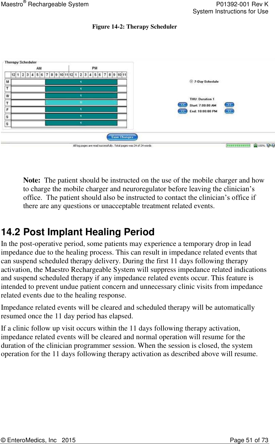
Enteromedics MC2402 Maestro Rechargeable System Mobile Charger User Manual
Enteromedics, Inc. Maestro Rechargeable System Mobile Charger
UserManual.wiki
>
Enteromedics
>
MC2402 User Manual
User Manual
Navigation menu
Upload a User Manual
Namespaces
Wiki Guide
HTML
PDF
Info
Views
User Manual
Discussion / Help
Navigation
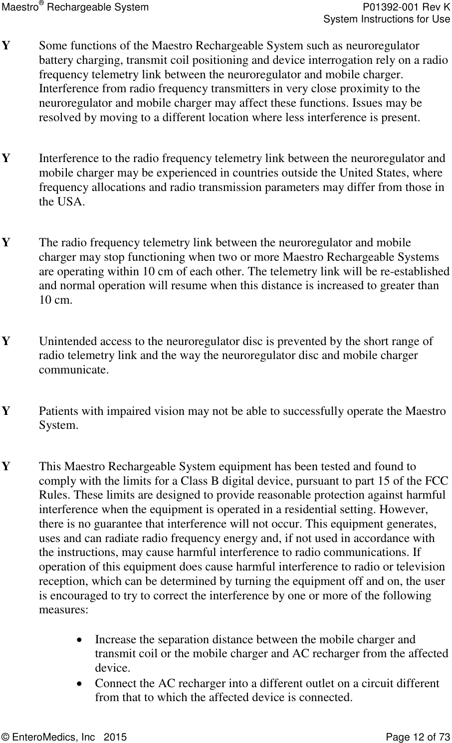

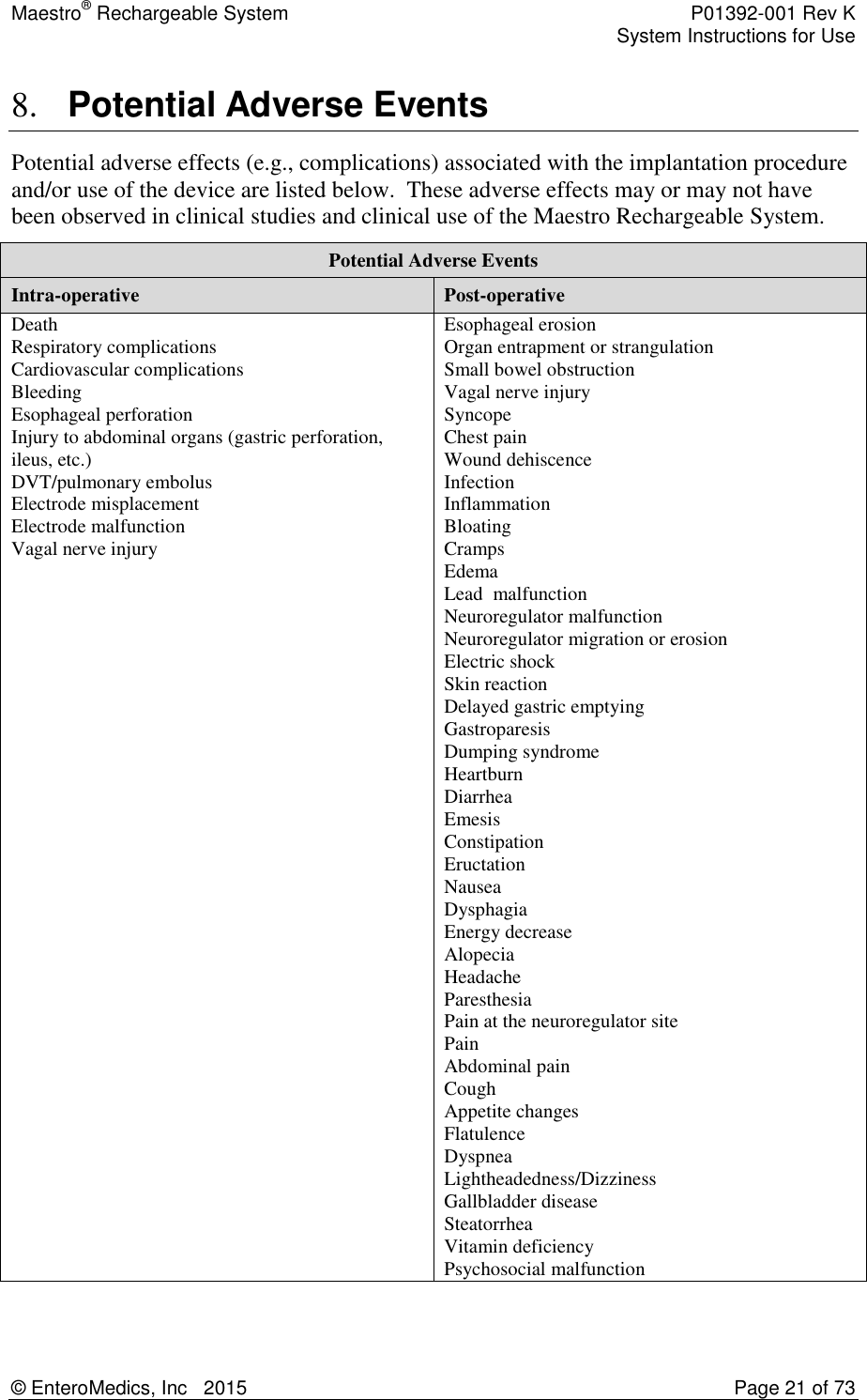
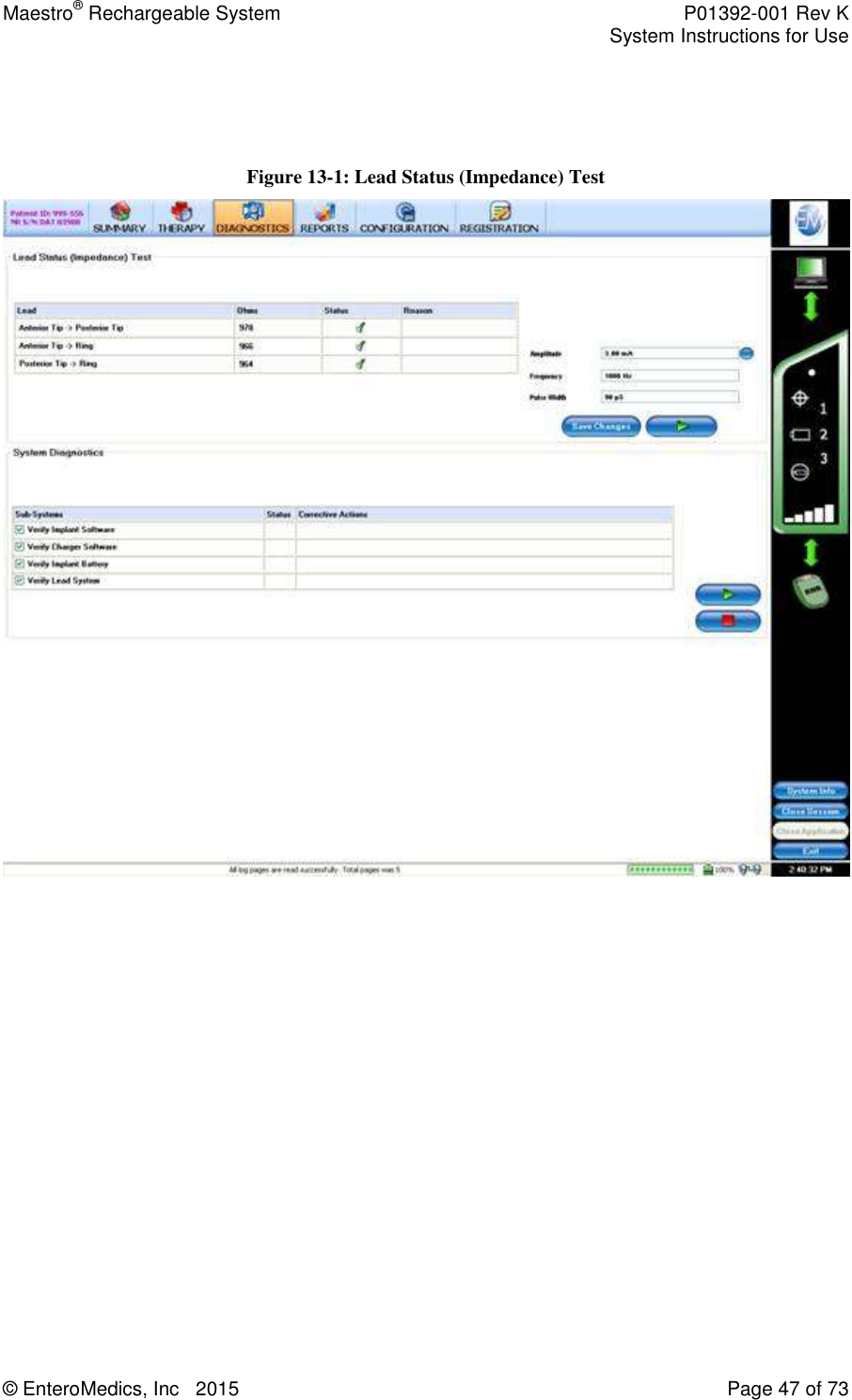
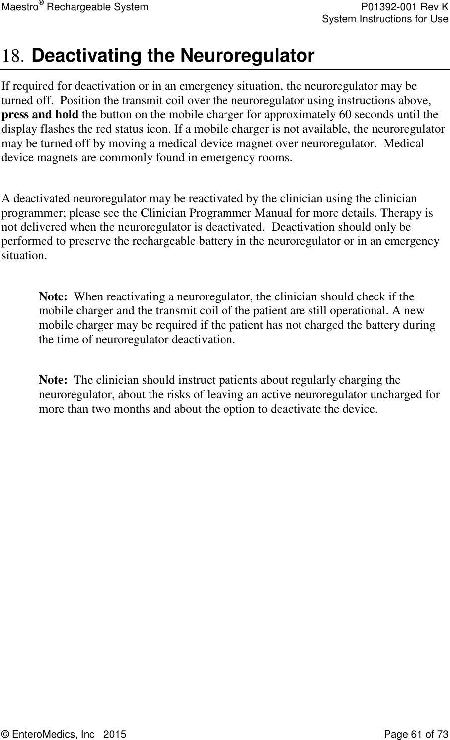
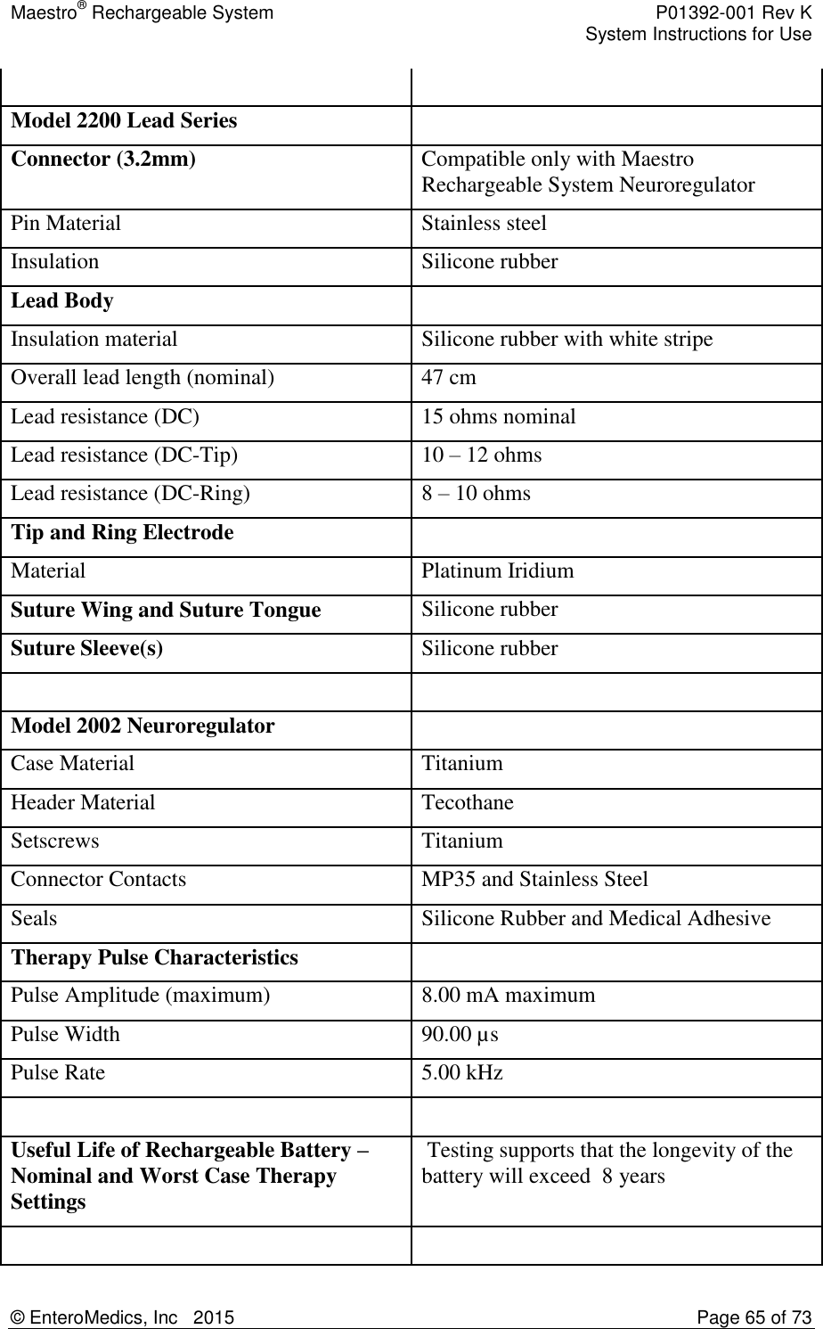
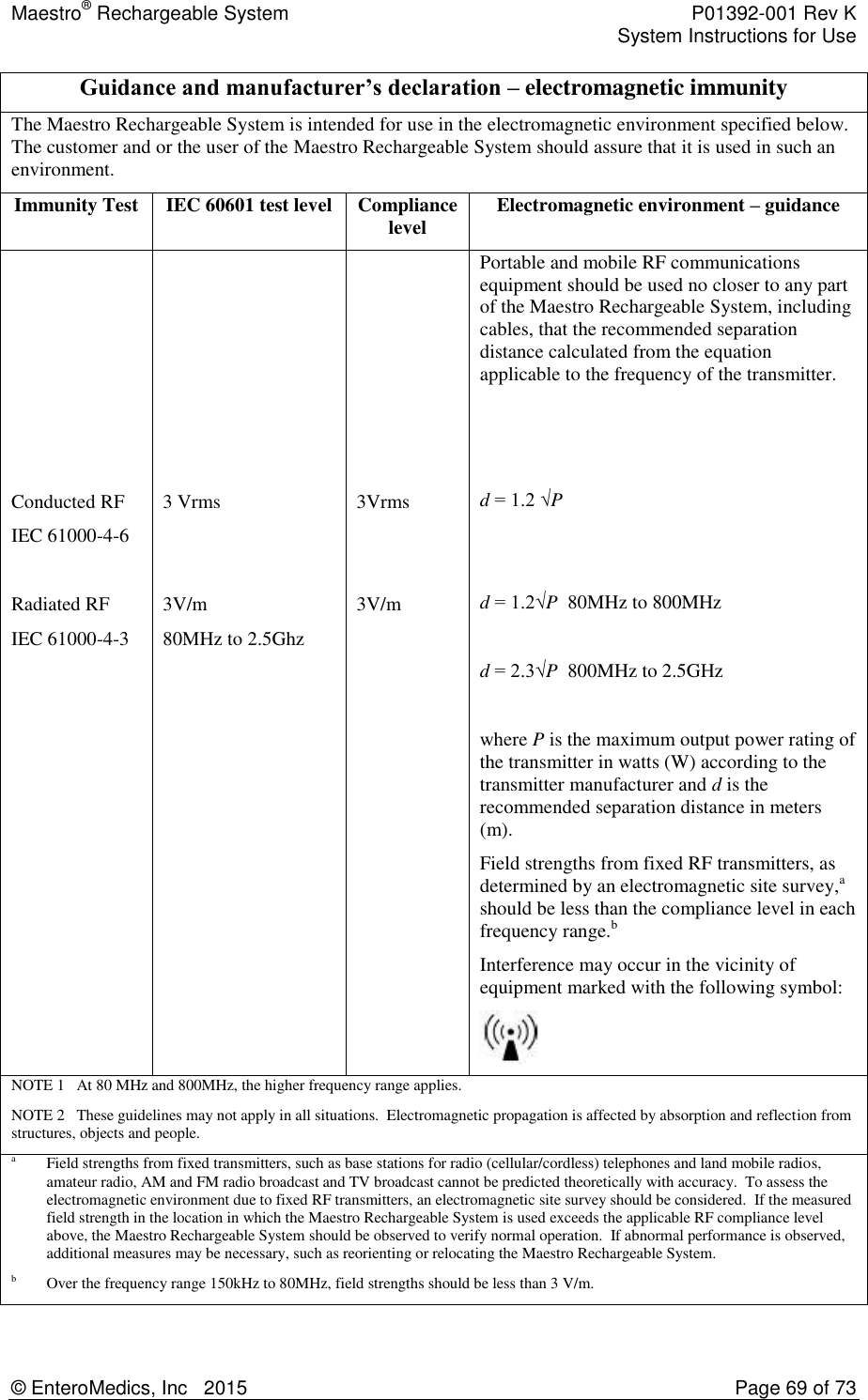
![Maestro® Rechargeable System P01392-001 Rev K System Instructions for Use © EnteroMedics, Inc 2015 Page 24 of 73 Characteristic VBLOC N=162 Sham Control N=77 P-value Dyslipidemia 91 (56.2%) 46 (59.7%) 0.884 Obstructive sleep apnea 33 (20.4%) 23 (29.9%) 0.267 Note: Data are presented as mean ± SD for continuous variables. Data are presented as n (%) for categorical variables. P-values for continuous variables were calculated using a Student's t-test (no asterisk) or a Wilcoxon rank sum test (*) if the variable was not normally distributed based on the Shapiro-Wilk normality test. Categorical variables were compared using Fisher's exact test. 9.4 Primary Safety Endpoint The primary safety SAE rate (Table 9-2), defined as the proportion of subjects in the VBLOC group who experienced an implant/revision procedure, device or therapy-related SAE through 12 months post-implant, was 3.7% (n=6; 95% CI: 1.4% to 7.9%) in the ITT population. This rate was significantly lower than 15% (p<0.0001), so the primary safety endpoint was met. The type, origin, and relatedness of these SAEs are shown in Table 9-3. All SAEs were adjudicated by the Clinical Events Committee (CEC). Table 9-2: Primary Safety Endpoint VBLOC Group SAE Rate (95% CI) [n/N] P-value (SAE Rate < 15%) 3.7% (1.4, 7.9) [6/162] <.0001 Table 9-3: Listing of Events for Primary Safety Endpoint Subject ID SAE Type SAE Origin (Relatedness) 301-303-RC Neuroregulator malfunction Device (Definite) 301-325-RC Pain, neuroregulator site Device (Definite) 311-309-RC Atelectasis Implant/revision procedure (Definite) 311-319-RC Neuroregulator malfunction Device (Definite) 313-323-RC Gallbladder disease Therapy algorithm (Possible) 317-309-RC Emesis (Vomiting) Implant/revision procedure (Definite) Considering all SAEs in the primary safety endpoint as well as those related to the general surgical procedure (e.g., nausea), the rate was 8.6% (Table 9-4), which was also significantly lower than 15%. These additional SAEs related to general surgical procedure included 6 cases of post-operative nausea, cirrhosis (subject not implanted), generalized ileus, and intra-operative oozing. Table 9-4: Rate of SAEs in Primary Safety Endpoint and SAEs Related to General Surgical Procedure](https://usermanual.wiki/Enteromedics/MC2402/User-Guide-2567422-Page-24.png)
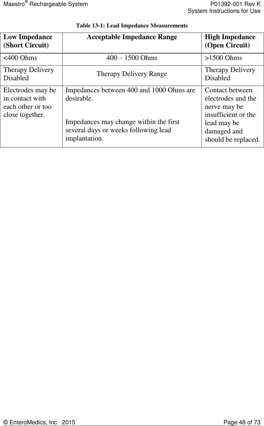
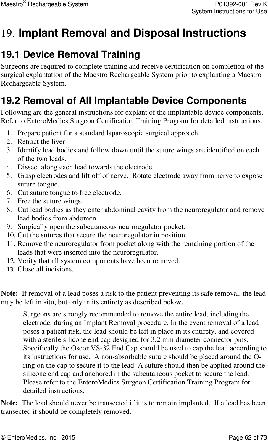
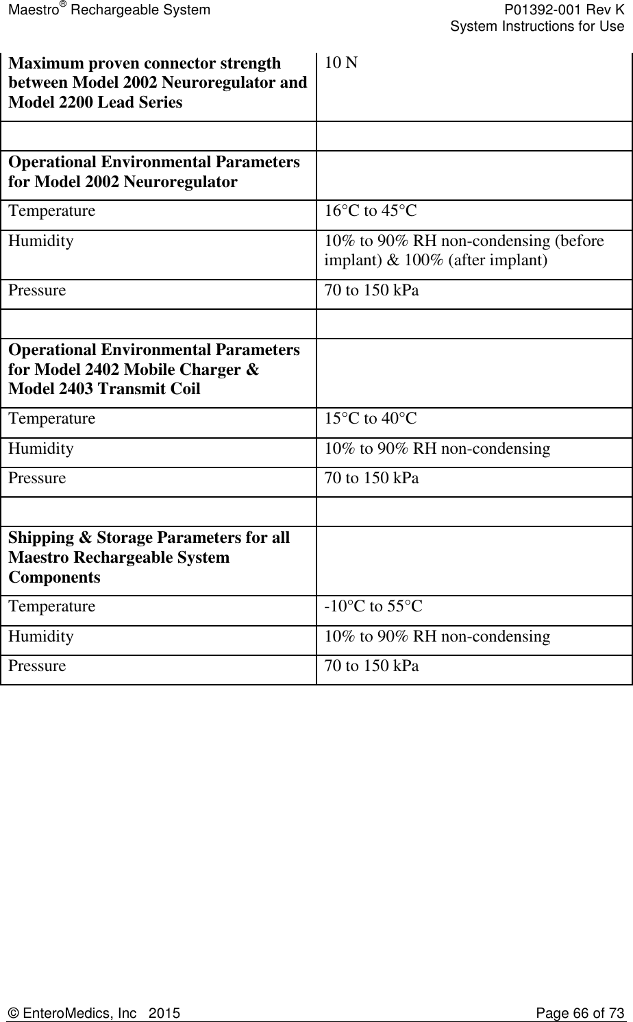
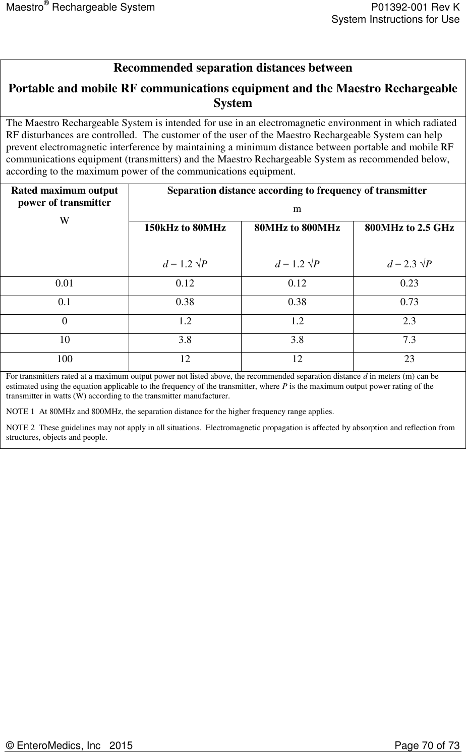
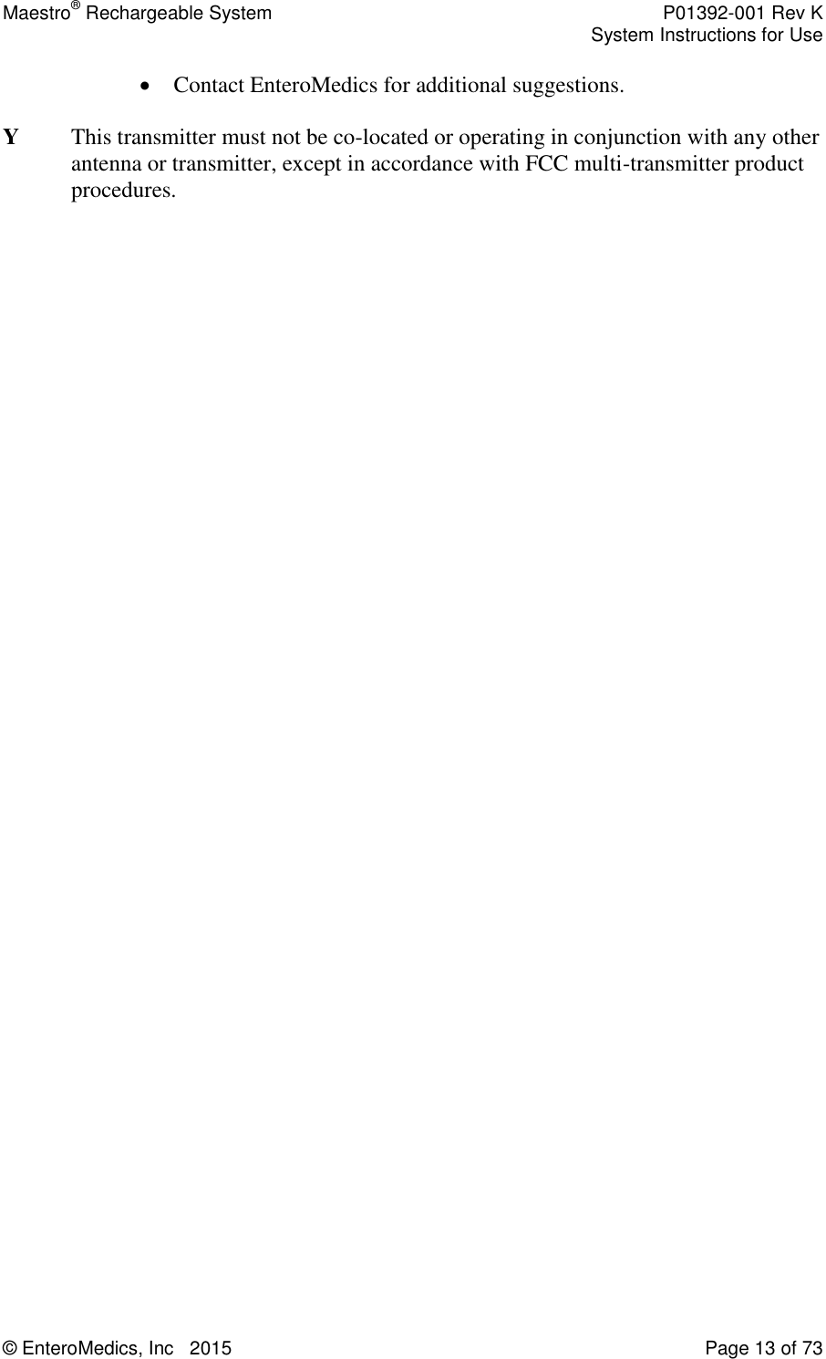
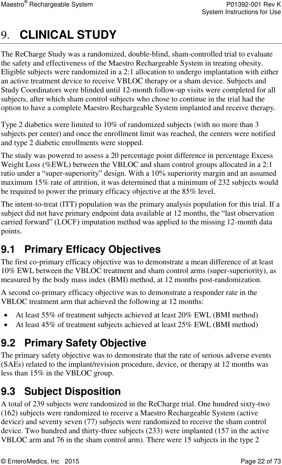
![Maestro® Rechargeable System P01392-001 Rev K System Instructions for Use © EnteroMedics, Inc 2015 Page 25 of 73 VBLOC Group SAE Rate (95% CI) [n/N] P-value (SAE Rate < 15%) 8.6% (4.8, 14.1) [14/162] 0.01 9.4.1 All Serious Adverse Events At 12 months, there were 27 SAEs among 22 VBLOC subjects (13.6%) and 4 SAEs among 4 sham control subjects (5.2%). All SAEs are listed by CEC-determined relatedness (Table 9-5). Table 9-5: Serious Adverse Events by CEC Category Serious Adverse Event VBLOC N=162 Sham Control N=77 N (%) subjects N events N (%) subjects N events SAEs related to device, implant/revision, or therapy Neuroregulator malfunction 2 (1.2) 2 0 (0.0) 0 Atelectasis 1 (0.6) 1 0 (0.0) 0 Gallbladder disease 1 (0.6) 1 0 (0.0) 0 Emesis/vomiting 1 (0.6) 1 0 (0.0) 0 Pain, neuroregulator site 1 (0.6) 1 0 (0.0) 0 SAEs related to general surgical procedure Nausea 6 (3.7) 6 0 (0.0) 0 Cirrhosis* 1 (0.6) 1 0 (0.0) 0 Generalized ileus 1 (0.6) 1 0 (0.0) 0 Intra-operative oozing 1 (0.6) 1 0 (0.0) 0 SAEs related to pre-existing condition or not related Allergic reaction 1 (0.6) 1 0 (0.0) 0 Chest pain 1 (0.6) 1 0 (0.0) 0 Colitis 1 (0.6) 1 0 (0.0) 0 Gallbladder disease 1 (0.6) 1 0 (0.0) 0 Gastritis 0 (0.0) 0 1 (1.3) 1 Infection, other 1 (0.6) 1 1 (1.3) 1 Osteoarthritis 1 (0.6) 1 0 (0.0) 0 Pain, abdominal 1 (0.6) 1 0 (0.0) 0 Pain, other 2 (1.2) 2 0 (0.0) 0](https://usermanual.wiki/Enteromedics/MC2402/User-Guide-2567422-Page-25.png)
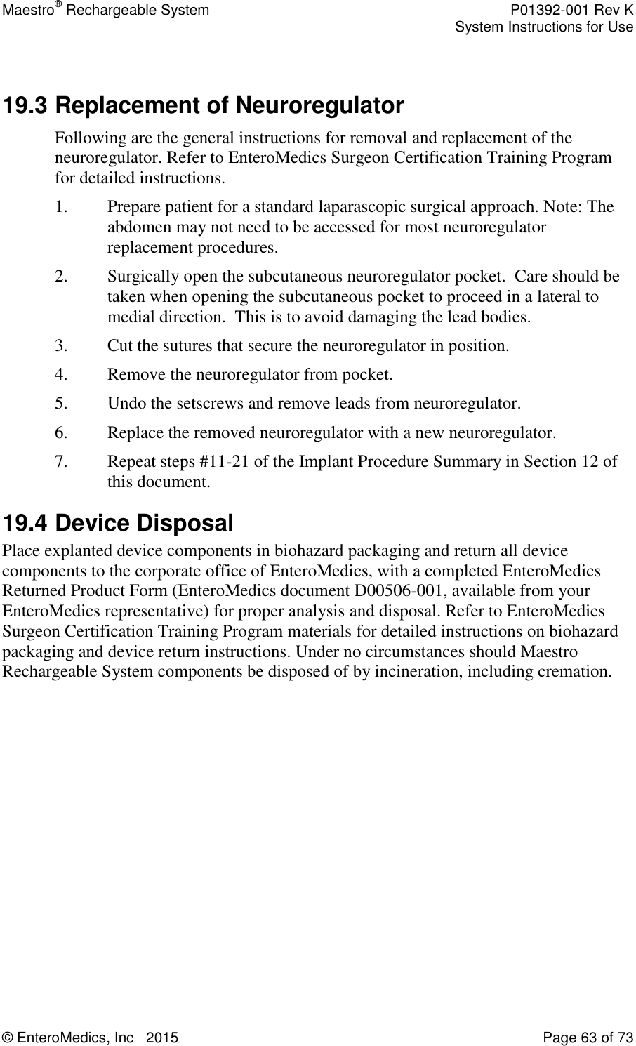
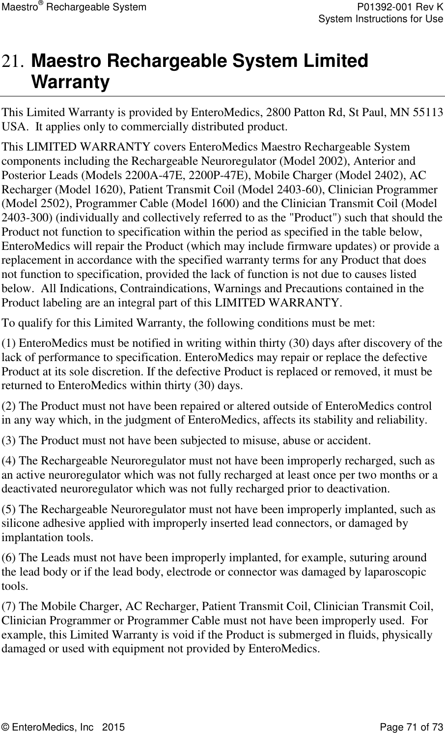
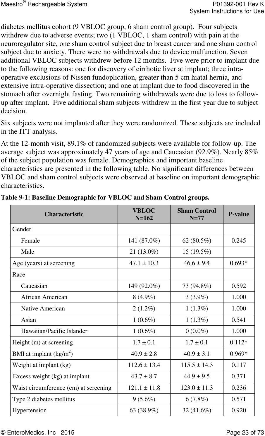
![Maestro® Rechargeable System P01392-001 Rev K System Instructions for Use © EnteroMedics, Inc 2015 Page 26 of 73 Serious Adverse Event VBLOC N=162 Sham Control N=77 N (%) subjects N events N (%) subjects N events Palpitations 1 (0.6) 1 0 (0.0) 0 Pericarditis 1 (0.6) 1 0 (0.0) 0 Breast cancer 0 (0.0) 0 1 (1.3) 1 Worsening back pain 0 (0.0) 0 1 (1.3) 1 * subject not implanted 9.4.2 Overview of All Adverse Events Related to Device, Therapy or Procedure The most common non-serious related AEs through 12 months are shown in Table 9-6. The most common AE in both groups was pain at the neuroregulator site, although there was no statistical difference between groups. The rates of other pain and heartburn were statistically higher in the VBLOC group. This is not unexpected considering the differences in surgical procedure and therapy between the treatment groups. Table 9-6: Most Common Non-Serious Adverse Events Related to Device, Implant/Revision Procedure, or Therapy through 12 Months among Implanted Patients AE Type VBLOC N=157 Sham Control N=76 Difference [95% CI] N patients (%) N events N patients (%) N events Pain, neuroregulator site 60 (38.2%) 72 32 (42.1%) 35 -3.9% [-17.5, 9.8] Other 34 (21.7%) 43 7 (9.2%) 10 12.4% [-1.4, 25.9] Heartburn/dyspepsia 38 (24.2%) 42 3 (3.9%) 3 20.3% [6.5, 33.5] Pain, other 38 (24.2%) 43 0 (0.0%) 0 24.2% [10.5, 37.3] Pain, abdominal 20 (12.7%) 26 2 (2.6%) 2 10.1% [-3.7, 23.7] Nausea 7 (4.5%) 8 1 (1.3%) 1 3.1% [-10.5, 16.8] Dysphagia 13 (8.3%) 13 0 (0.0%) 0 8.3% [-5.4, 21.8] Eructation/belching 13 (8.3%) 13 0 (0.0%) 0 8.3% [-5.4, 21.8] Chest pain 9 (5.7%) 9 2 (2.6%) 2 3.1% [-10.6, 16.8] 9.4.3 Adverse Events Leading to Study Withdrawal There were four adverse events that led to withdrawal from the study before the 12-month visit. In the VBLOC group, one subject (0.6%) withdrew due to pain at the neuroregulator site. Three subjects (3.9%) in the sham control group withdrew for pain at the neuroregulator site, anxiety, and breast cancer, respectively.](https://usermanual.wiki/Enteromedics/MC2402/User-Guide-2567422-Page-26.png)
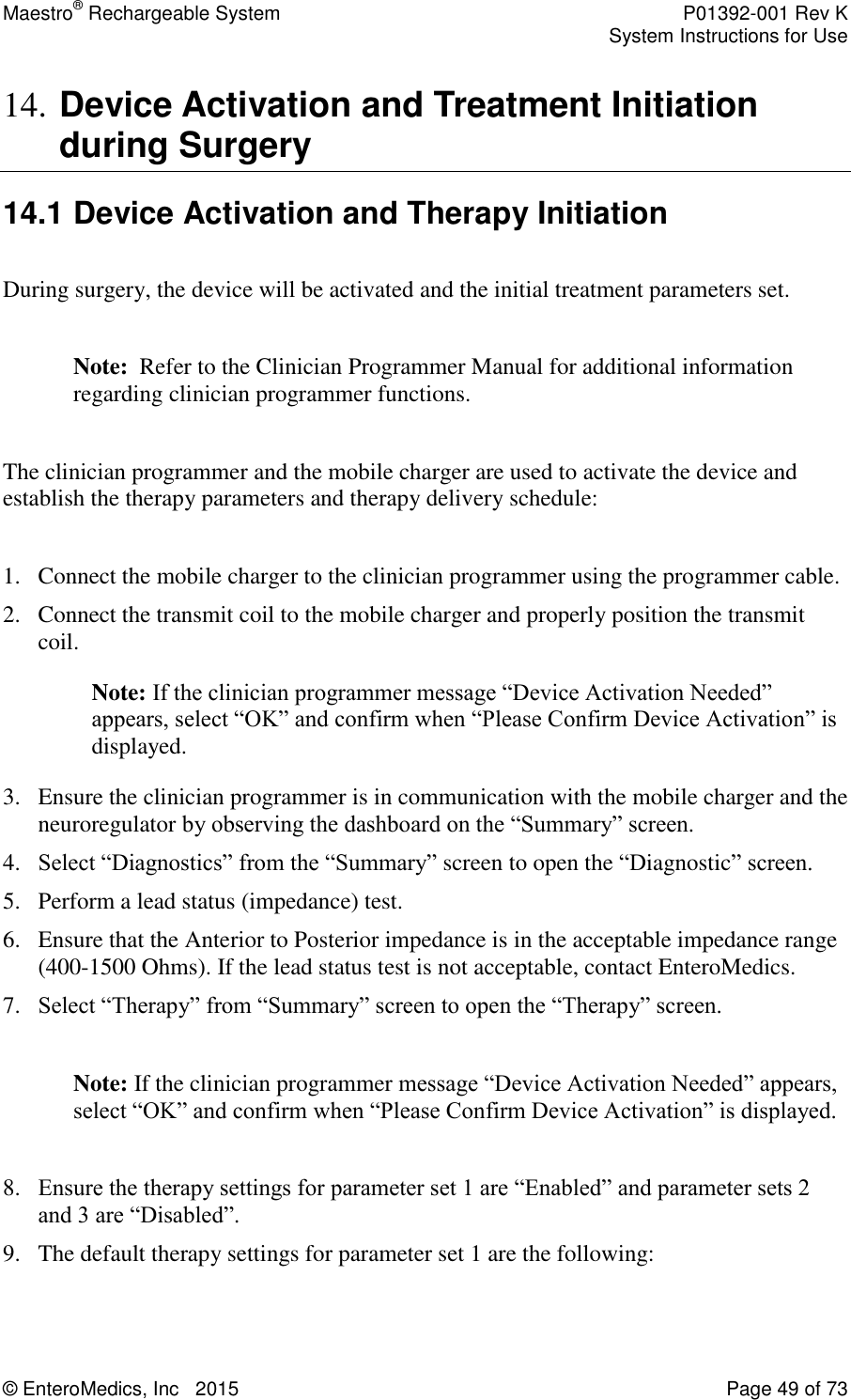
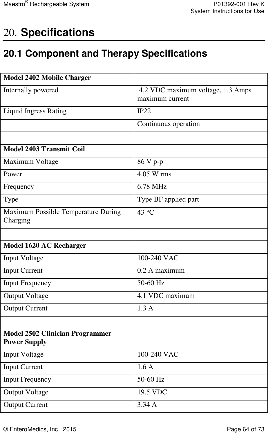
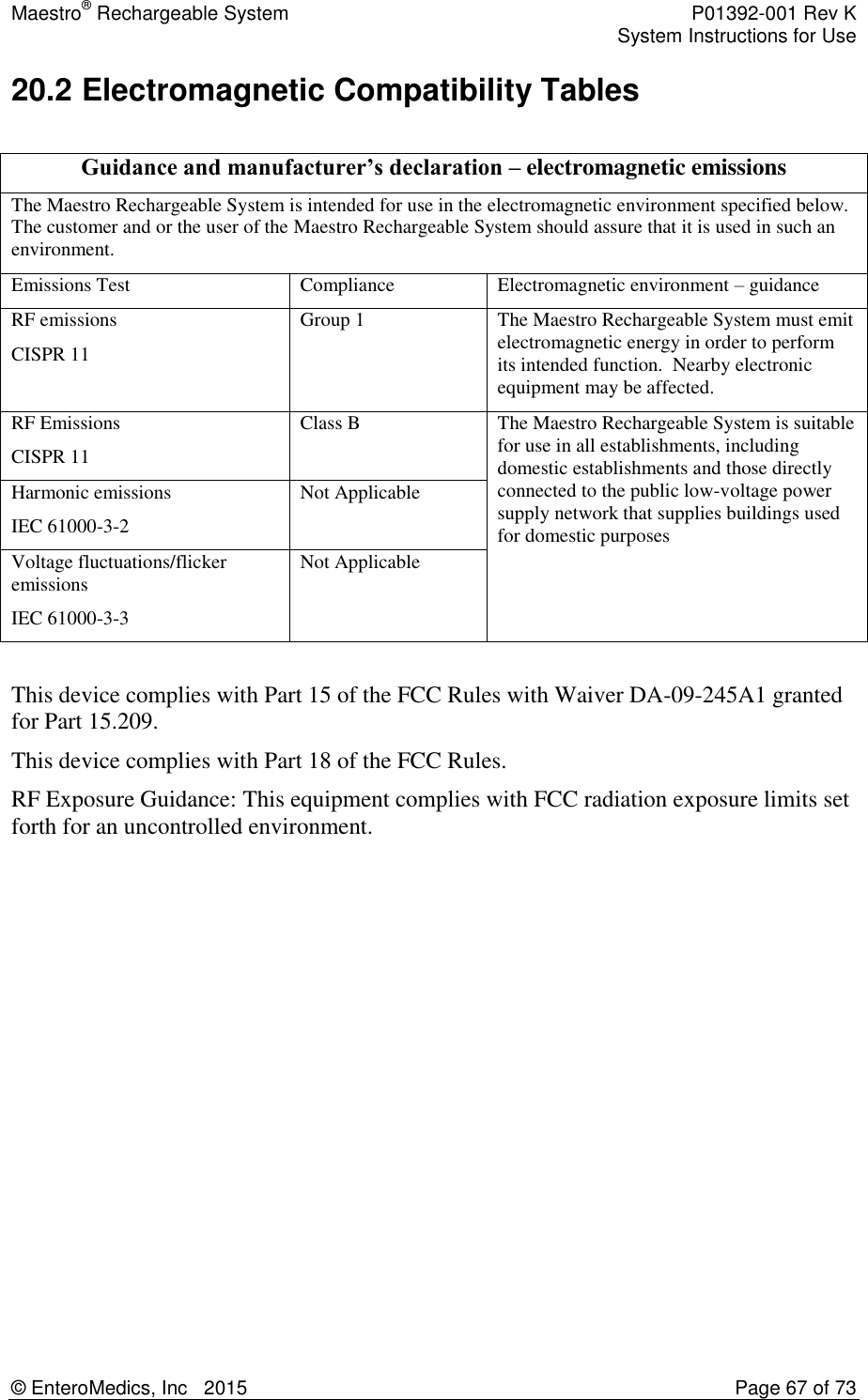
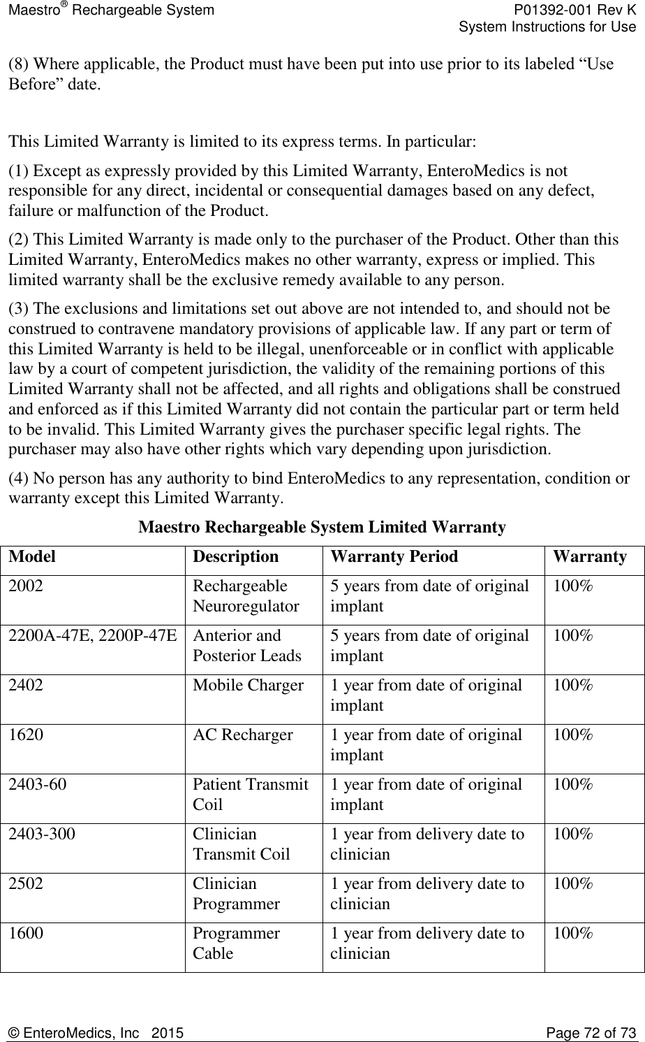
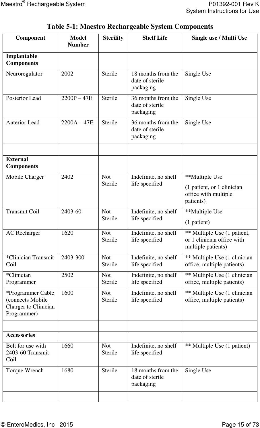
![Maestro® Rechargeable System P01392-001 Rev K System Instructions for Use © EnteroMedics, Inc 2015 Page 29 of 73 9.5.2 Responder Analyses At 12 months in the ITT population, the VBLOC group had 52.5% of subjects with 20% or greater EWL and 38.3% of subjects with 25% or greater EWL, which did not meet the respective performance goals of 55% and 45%. The sham control group had 32.5% of subjects with 20% or greater EWL and 23.4% of subjects with 25% or greater EWL. Responder analyses were conducted comparing the percentage of subjects in each group who achieved levels of response between 20% and 50%. As shown in Table 9-7, there is a statistically significant treatment benefit over sham surgical control at all %EWL thresholds from 20% EWL and above. The difference in responder rates is also presented using odds ratios. The VBLOC group has significantly higher odds of achieving higher %EWL thresholds over sham control at every threshold from 20% and above. Table 9-7: %EWL Thresholds from Implant in ITT Population %EWL Achieved VBLOC N=162 Sham Control N=77 OR [95% CI] 20% EWL 85 (52.5%) 25 (32.5%) 2.3 [1.3, 4.1] 25% EWL 62 (38.3%) 18 (23.4%) 2.0 [1.1, 3.8] 30% EWL 49 (30.2%) 14 (18.2%) 2.0 [1.0, 3.8] 40% EWL 35 (21.6%) 4 (5.2%) 5.0 [1.7, 14.7] 50% EWL 24 (14.8%) 1 (1.3%) 13.2 [1.8, 99.6] 9.5.3 Improvements in Obesity Risk Factors Table 9-8 illustrates the improvements seen in obesity risk factors for the VBLOC and sham control groups. All obesity risk factors trended toward improvement with VBLOC therapy and in the sham control group. Improvements in patient questionnaires (i.e., IWQoL, Three Factor Eating Questionnaire) were also observed consistent with the weight loss. Table 9-8: Change in Obesity Risk Factors at 12 Months Risk Factor VBLOC Sham Control Screening Mean [95% CI] Mean Change from Screening [95% CI] Screening Mean [95% CI] Mean Change from Screening [95% CI] Metabolic Total Cholesterol (mg/dL) 204.2 [198.3, 210.2] -8.7 [-13.5, -3.8] 204.8 [196.5, 213.2] -9.7 [-16.9, -2.6] LDL Cholesterol (mg/dL) 121.9 [116.8, 127.0] -5.2 [-9.6, -0.9] 122.5 [115.8, 129.2] -4.3 [-10.2, 1.7] HDL Cholesterol (mg/dL) 54.3 [51.9, 56.6] 1.0 [-0.5, 2.5] 53.6 [49.3, 57.9] -0.4 [-3.0, 2.3] Triglycerides (mg/dL) 141 [131, 151] -21 [-31, -12] 151 [127, 175] -33 [-48, 18]](https://usermanual.wiki/Enteromedics/MC2402/User-Guide-2567422-Page-29.png)
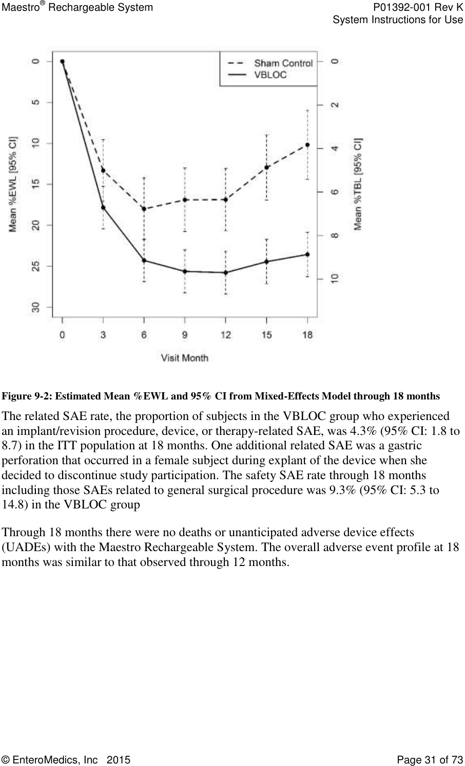
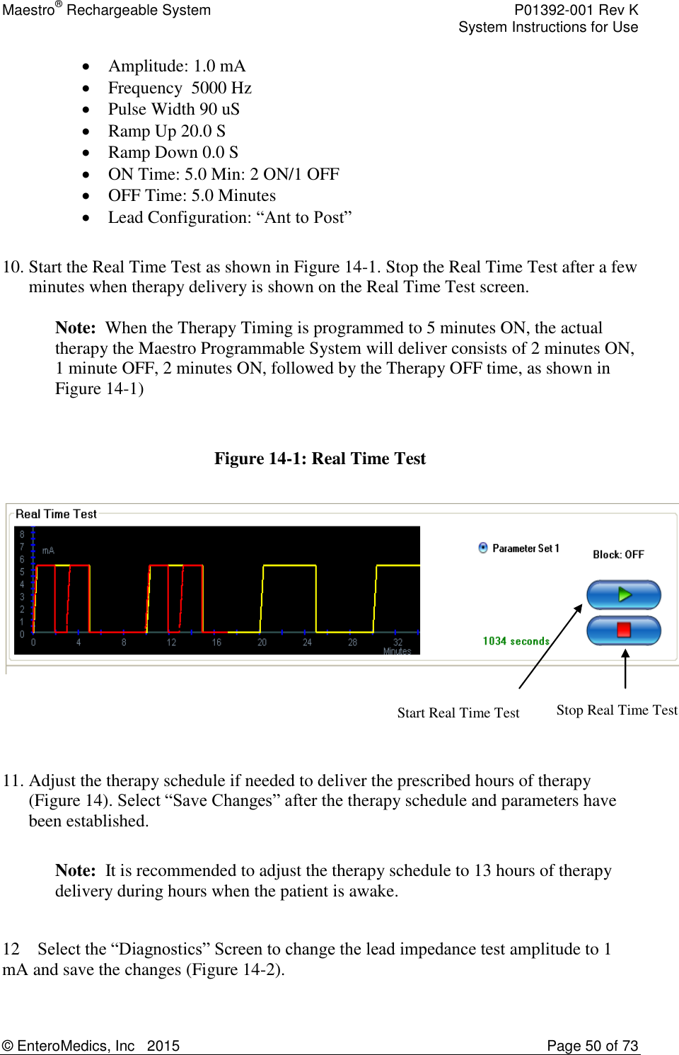
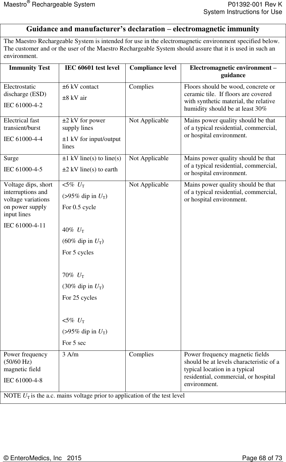
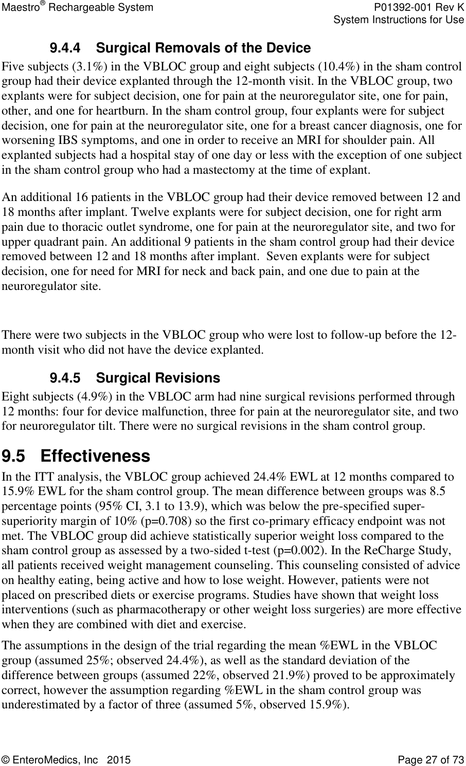
![Maestro® Rechargeable System P01392-001 Rev K System Instructions for Use © EnteroMedics, Inc 2015 Page 30 of 73 Risk Factor VBLOC Sham Control Screening Mean [95% CI] Mean Change from Screening [95% CI] Screening Mean [95% CI] Mean Change from Screening [95% CI] Fasting Plasma Glucose (mg/dL) 96.6 [93.7, 99.5] -1.5 [-4.1, 1.0] 98.4 [89.8,106.9] -0.7 [-3.5, 2.2] HbA1c (%) 5.66 [5.56, 5.77] -0.33 [-0.40, -0.26] 5.85 [5.52, 6.18] -0.31 [-0.43, -0.20] Cardiovascular Systolic Blood Pressure (mmHg) 127.4 [125.4, 129.4] -5.5 [-7.8, -3.2] 129.5 [126.3, 132.7] -4.0 [-7.3, -0.7] Diastolic Blood Pressure (mmHg) 80.7 [79.2, 82.2] -2.8 [-4.3, -1.2] 81.5 [79.1, 84.0] -4.5 [-6.5, -2.4] Heart Rate (bpm) 76.2 [74.7, 77.8] -3.6 [-5.3, -1.9] 74.8 [72.3, 77.3] -3.5 [-6.3, -0.7] Anthropometric Waist Circumference (cm) 121 [120, 123] -10 [-12, -8] 123 [120, 125] -8 [-10, -6] 9.6 Updated Results through 18 Months Complete data were collected on 159 subjects (117 VBLOC and 42 sham control) at 18 months. Since the trial remained blinded until all subjects had completed the 12-month visit, most subjects remained blinded for several months after the 12-month visit. The median time to unblinding was 16 months for both groups. Specifically, at 15 months, 84% of VBLOC subjects and 90% of sham control subjects (86% total) remained blinded. At 18 months, 27% of VBLOC subjects and 25% of sham control subjects (26% total) remained blinded. Efficacy through 18 months was assessed using three statistical techniques: a mixed-effects regression model, the LOCF methodology, as well as without imputation. Results from the mixed-effects model suggest that weight loss with VBLOC therapy was durable, with an estimated mean 25.8% EWL at 12 months, 24.4% at 15 months, and 23.5% EWL at 18 months. The sham control group regained a significant amount of weight following the 12-month visit, with an estimated mean %EWL of 16.9% at 12 months, 12.9% at 15 months, and 10.1% at 18 months. The treatment difference increased from 8.9 percentage points (95% CI: 4.3 to 13.5) at 12 months to 13.4 percentage points (95% CI: 8.4 to 18.4) at 18 months. This increase in relative efficacy as a result of the sham control group gaining weight cannot be largely attributed to unblinding since most subjects remained blinded until the 16-month visit.](https://usermanual.wiki/Enteromedics/MC2402/User-Guide-2567422-Page-30.png)