Enterprise Electronics DWSR-2001X Multi-Mode Radar System User Manual DWSR 2001 2
Enterprise Electronics Corporation Multi-Mode Radar System DWSR 2001 2
Contents
- 1. DWSR 2001X User Manual 1
- 2. DWSR 2001 User Manual 2
DWSR 2001 User Manual 2

CHAPTER 8 INTERFACE CONTROL DOCUMENTS (ICD)
APPENDIX A INTERFACE CONTROL DOCUMENTS (ICD)
ISSUE/REVISION DATE: 25 JULY 2007 TECHNICAL MANUAL
ISO 9001:2000 PROPRIETARY
Interface Control Document (ICD) ENTERPRISE ELECTRONICS CORPORATION
Rev No. 5 Page 1 of 21
Issue Date 25 July 2007 UM-130365
Distribution Data Collection
Module (DDC)
THE DATA PRESENTED HEREIN REPRESENTS THE INTELLECTUAL PROPERTY OF ENTERPRISE ELECTRONICS CORPORATION (EEC). THIS DATA MAY NOT BE DISTRIBUTED OR REPRODUCED BY
ANY MEANS WITHOUT THE EXPRESS, WRITTEN CONSENT OF EEC.
ENTERPRISE ELECTRONICS CORPORATION
128 SOUTH INDUSTRIAL BLVD.
ENTERPRISE, ALABAMA 36330
TELEPHONE: (334) 347-3478
FAX: (334) 393-4556
EMAIL: SALES@EECRADAR.COM
Distribution Data Collection Module (DDC)
User Manual

CHAPTER 8 INTERFACE CONTROL DOCUMENTS (ICD)
APPENDIX A INTERFACE CONTROL DOCUMENTS (ICD)
ISSUE/REVISION DATE: 25 JULY 2007 TECHNICAL MANUAL
ISO 9001:2000 PROPRIETARY
Interface Control Document (ICD) ENTERPRISE ELECTRONICS CORPORATION
Rev No. 5 Page 2 of 21
Issue Date 25 July 2007 UM-130365
Distribution Data Collection
Module (DDC)
THE DATA PRESENTED HEREIN REPRESENTS THE INTELLECTUAL PROPERTY OF ENTERPRISE ELECTRONICS CORPORATION (EEC). THIS DATA MAY NOT BE DISTRIBUTED OR REPRODUCED BY
ANY MEANS WITHOUT THE EXPRESS, WRITTEN CONSENT OF EEC.
Official Enterprise Electronics Corporation (EEC®) Indemnification Clause
The technical data and information (hereinafter “technical data”) contained herein is highly confidential and pro-
prietary in nature and is the sole and exclusive intellectual property of the Enterprise Electronics Corporation
(EEC®). Any company, organization, entity or individual who seeks to benefit from the use of this technical data
(“User”) agrees to hold said information in strict confidence. User agrees that, unless required by law, it shall not
disclose or make the technical data available in any form to a third party without the specific express written con-
sent of EEC® with regard to each such third party. User agrees to take all necessary steps to ensure that Intellec-
tual Property is not disclosed or distributed by its Directors, Officers, employees, representatives or agents in viola-
tion of this condition.
The User of the technical data contained herein agrees to defend (using counsel of EEC’s choosing), indemnify and
hold harmless EEC®, its Directors, Officers and its employees, parent company, affiliate companies and/or
subsidiaries, its successors and assigns, customers and users of its Product(s) against all suits at law or in equity
and from damages, claims and demands arising out of the death or injury to any person or damage of any kind to
User's Directors, Officers, employees, agents or property as a result of User's use, misuse, assumptions or interpre-
tations of the technical data contained herein.
EEC® has made its best effort to offer the most current, correct, and clearly expressed information possible. Nev-
ertheless, inadvertent errors in information may occur. In particular, but without limitation to the above, EEC®
disclaims any responsibility for typographical errors or punctuation errors contained herein.
EEC® is a Registered Trademark of Enterprise Electronics Corporation.
StarDrive™ is a Trademark of EEC®.
EDRP-9™ is a Trademark of EEC®.
ERCP-9™ is a Trademark of EEC®.
Simultaneous dual polarization radar systems offered by EEC® are covered by one or more of the follow patents:
US 6,859,163.
US 6,803,875.
US 7,049,997
Various additional domestic and international patents have been applied for.
Validity Date: 08 Mar 07

CHAPTER 8 INTERFACE CONTROL DOCUMENTS (ICD)
APPENDIX A INTERFACE CONTROL DOCUMENTS (ICD)
ISSUE/REVISION DATE: 25 JULY 2007 TECHNICAL MANUAL
ISO 9001:2000 PROPRIETARY
Interface Control Document (ICD) ENTERPRISE ELECTRONICS CORPORATION
Rev No. 5 Page 3 of 21
Issue Date 25 July 2007 UM-130365
Distribution Data Collection
Module (DDC)
THE DATA PRESENTED HEREIN REPRESENTS THE INTELLECTUAL PROPERTY OF ENTERPRISE ELECTRONICS CORPORATION (EEC). THIS DATA MAY NOT BE DISTRIBUTED OR REPRODUCED BY
ANY MEANS WITHOUT THE EXPRESS, WRITTEN CONSENT OF EEC.
1.0 DDC MODULE DESCRIPTION .......................................................................... 4
2.0 DDC HARDWARE INTERFACE ........................................................................ 5
2.1 DDC GENERAL SPECIFICATIONS ........................................................................... 5
2.2 RS232 PORTS (J1) ................................................................................................. 5
2.2.1 RS232 Pinouts on J1 ..................................................................................... 6
2.3 POWER INPUT (J2) ................................................................................................. 6
2.3.1 Power Pinouts on J2 ..................................................................................... 6
2.4 I/O PORTS (J3,J4) .................................................................................................. 7
2.4.1 I/O Pinouts on J3 .......................................................................................... 10
2.4.2 I/O Pinouts on J4 .......................................................................................... 11
2.5 ETHERNET (J5) ...................................................................................................... 12
3.0 SOFTWARE INTERFACE ................................................................................... 12
3.1 SERIAL CONTROL .................................................................................................. 12
3.2 ETHERNET CONTROL ............................................................................................. 12
3.3 UPDATING THE ON-BOARD SOFTWARE .................................................................. 12
3.3.1 Monitor Program .......................................................................................... 12
3.3.2 Main DDC Program ..................................................................................... 12
4.0 TROUBLESHOOTING THE DDC ...................................................................... 13
4.1 LED INDICATORS .................................................................................................. 13
APPENDIX A – SOFTWARE LOADING ........................................................................ 14
INTRODUCTION ................................................................................................................... 14
TERMINAL SETUP ............................................................................................................... 14
INTERRUPTING THE BOOT PROCESS .................................................................................... 15
OPERATIONAL PARAMETER CONFIGURATION .................................................................... 16
Network Configuration .................................................................................................. 16
MAC Address ............................................................................................................ 17
Additional Configuration ............................................................................................... 17
Wait ............................................................................................................................ 17
Boot To ...................................................................................................................... 17
Exceptions Cause ....................................................................................................... 17
Watch Dog ................................................................................................................. 18
Quiet/Loud Boot ........................................................................................................ 18
APPLICATION FIRMWARE DOWNLOAD ............................................................................... 18
Personality Configuration ............................................................................................. 21
CHAPTER 8 INTERFACE CONTROL DOCUMENTS (ICD)
APPENDIX A INTERFACE CONTROL DOCUMENTS (ICD)
ISSUE/REVISION DATE: 25 JULY 2007 TECHNICAL MANUAL
ISO 9001:2000 PROPRIETARY
Interface Control Document (ICD) ENTERPRISE ELECTRONICS CORPORATION
Rev No. 5 Page 4 of 21
Issue Date 25 July 2007 UM-130365
Distribution Data Collection
Module (DDC)
THE DATA PRESENTED HEREIN REPRESENTS THE INTELLECTUAL PROPERTY OF ENTERPRISE ELECTRONICS CORPORATION (EEC). THIS DATA MAY NOT BE DISTRIBUTED OR REPRODUCED BY
ANY MEANS WITHOUT THE EXPRESS, WRITTEN CONSENT OF EEC.
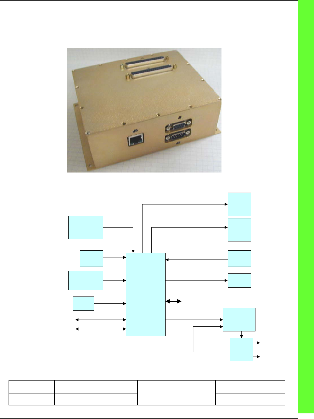
1.0 DDC Module Description
The Distributed Data Collection (DDC) module is an Ethernet, CAN, or serial RS232 controlled
device that collects both analog and digital data as well as controls relays. It outputs TTL sig-
nals under processor control.
DDC MODULE
PROCESSOR
ETHERNET
3 x RS232
16 TTL
INPUTS
8 TTL
OUTPUTS
10
RELAY
DRIVERS
8 INPUT
AUTORANGING
DVM
8 X 10 BIT
ADC
5 TO 30
VDC POWER
INPUT
CONFIGURABLE
EXPANSION
PORT
TEMP
SENSOR
2
SOURCE
DRIVERS
TRIGGER
PROTECTION
GENERATION
TRIGGER X 2
2X
50 OHM
BUFFER
5 TO 30
VDC POWER
INPUT
DDC BLOCK DIAGRAM
CHAPTER 8 INTERFACE CONTROL DOCUMENTS (ICD)
APPENDIX A INTERFACE CONTROL DOCUMENTS (ICD)
ISSUE/REVISION DATE: 25 JULY 2007 TECHNICAL MANUAL
ISO 9001:2000 PROPRIETARY
Interface Control Document (ICD) ENTERPRISE ELECTRONICS CORPORATION
Rev No. 5 Page 5 of 21
Issue Date 25 July 2007 UM-130365
Distribution Data Collection
Module (DDC)
THE DATA PRESENTED HEREIN REPRESENTS THE INTELLECTUAL PROPERTY OF ENTERPRISE ELECTRONICS CORPORATION (EEC). THIS DATA MAY NOT BE DISTRIBUTED OR REPRODUCED BY
ANY MEANS WITHOUT THE EXPRESS, WRITTEN CONSENT OF EEC.
2.0 DDC Hardware Interface
2.1 DDC General Specifications
The DDC module uses a Motorola 5282, 32-Bit processor core module with Ethernet on a Carrier PCA.
The Carrier PCA handles all power supply requirements and signal conditioning for the core processor
module. A Complex Programmable Logic Device (CPLD) is included on the carrier PCA to handle
logic and expansion. Serial ports are buffered on the carrier PCA and routed to the core processor mod-
ule.
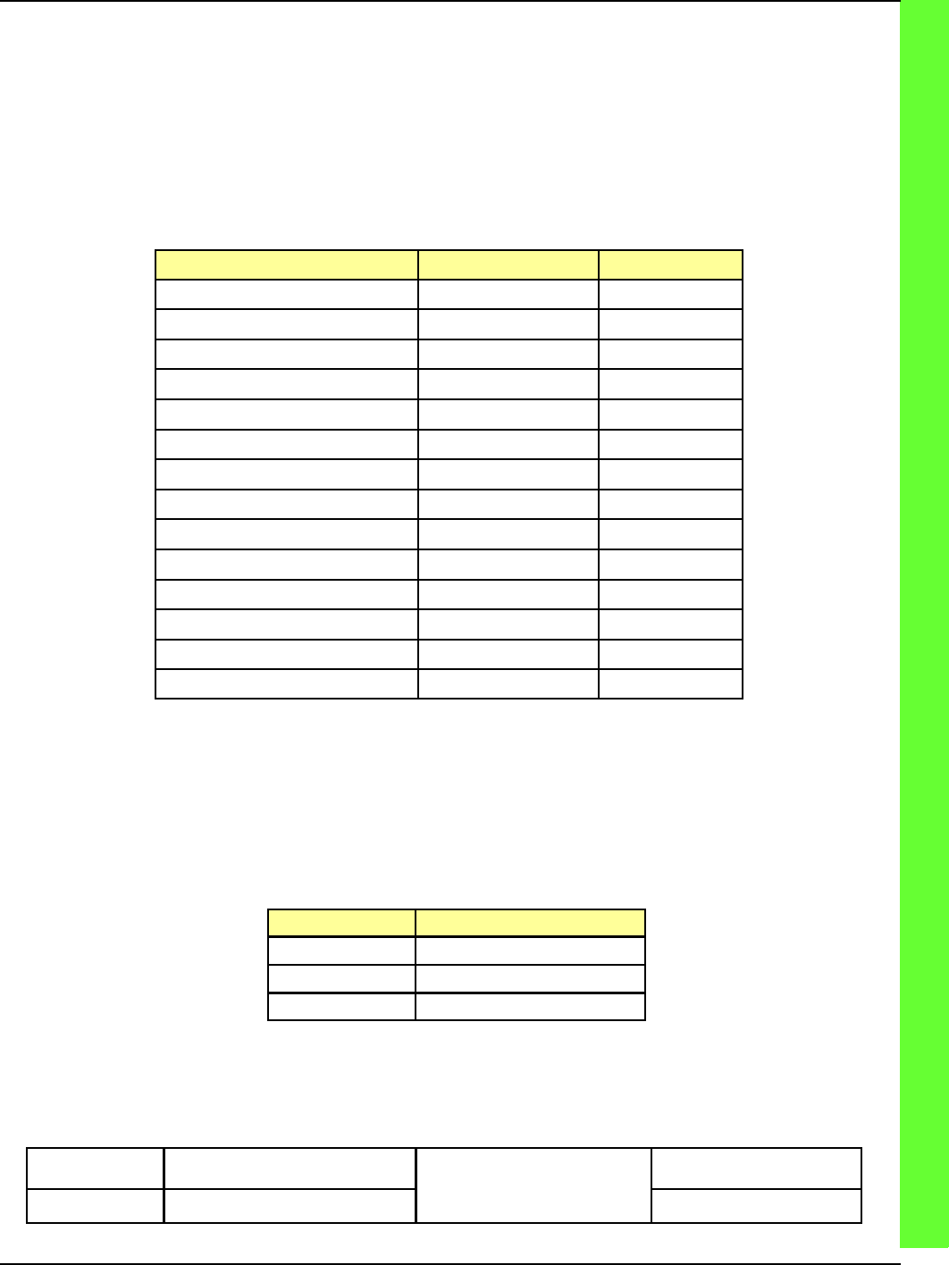
General specifications are listed in Table 1
Specification Value Limit
Power supply +5 to +30 VDC 250ma
Temperature -20 to +120F
RS232 Serial ports 3 RS232 Levels
CAN bus port 1
10 bit ADC channels 8 0-5VDC
DC Voltmeter Inputs 8 +-200 VDC
Discrete Inputs 16 0-30 VDC
TTL outputs 8 40ma
Sink Relay drive outputs 10 500ma
Source +24VDC outputs 2 500ma
Trigger inputs 2 24V peak
Trigger outputs 2 15V or 5V
Programmable Expansion 16 TTL
10/100 Ethernet port 1 10/100
Table 1 - DDC Specifications
2.2 RS232 Ports (J1)
The three DDC RS232 ports are accessible through the 9-pin connector, J1 are listed in Table 2.
Serial Port Usage
Port 0 Processor console
Port 1 General purpose
Port 0 General purpose
Table 2 – RS232 Serial Ports (J1)

CHAPTER 8 INTERFACE CONTROL DOCUMENTS (ICD)
APPENDIX A INTERFACE CONTROL DOCUMENTS (ICD)
ISSUE/REVISION DATE: 25 JULY 2007 TECHNICAL MANUAL
ISO 9001:2000 PROPRIETARY
Interface Control Document (ICD) ENTERPRISE ELECTRONICS CORPORATION
Rev No. 5 Page 6 of 21
Issue Date 25 July 2007 UM-130365
Distribution Data Collection
Module (DDC)
THE DATA PRESENTED HEREIN REPRESENTS THE INTELLECTUAL PROPERTY OF ENTERPRISE ELECTRONICS CORPORATION (EEC). THIS DATA MAY NOT BE DISTRIBUTED OR REPRODUCED BY
ANY MEANS WITHOUT THE EXPRESS, WRITTEN CONSENT OF EEC.
2.2.1 RS232 Pinouts on J1
The RS232 uses a 9 pin D connector but it is used in a NON-STANDARD way: all three serial
ports reside on this connector. These communication ports are simple TX/RX serial ports and do
not have hardware flow control.
Pin Function
1 Ground
2 Port 0 RX
3 Port 0 TX
4 Ground
5 Ground
6 Port 1 TX
7 Port 1 RX
8 Port 2 TX
9 Port 2 RX
Table 3 – RS232 Pinout on J1
2.3 Power Input (J2)
2.3.1 Power Pinouts on J2
Pin Function
1 CAN
2 CAN
3 Ground
4 +24vDC in
5 N/C
6 +24vDC in
7 CAN
8 CAN
9 Ground
Table 4 – Power Pinout
CHAPTER 8 INTERFACE CONTROL DOCUMENTS (ICD)
APPENDIX A INTERFACE CONTROL DOCUMENTS (ICD)
ISSUE/REVISION DATE: 25 JULY 2007 TECHNICAL MANUAL
ISO 9001:2000 PROPRIETARY
Interface Control Document (ICD) ENTERPRISE ELECTRONICS CORPORATION
Rev No. 5 Page 7 of 21
Issue Date 25 July 2007 UM-130365
Distribution Data Collection
Module (DDC)
THE DATA PRESENTED HEREIN REPRESENTS THE INTELLECTUAL PROPERTY OF ENTERPRISE ELECTRONICS CORPORATION (EEC). THIS DATA MAY NOT BE DISTRIBUTED OR REPRODUCED BY
ANY MEANS WITHOUT THE EXPRESS, WRITTEN CONSENT OF EEC.
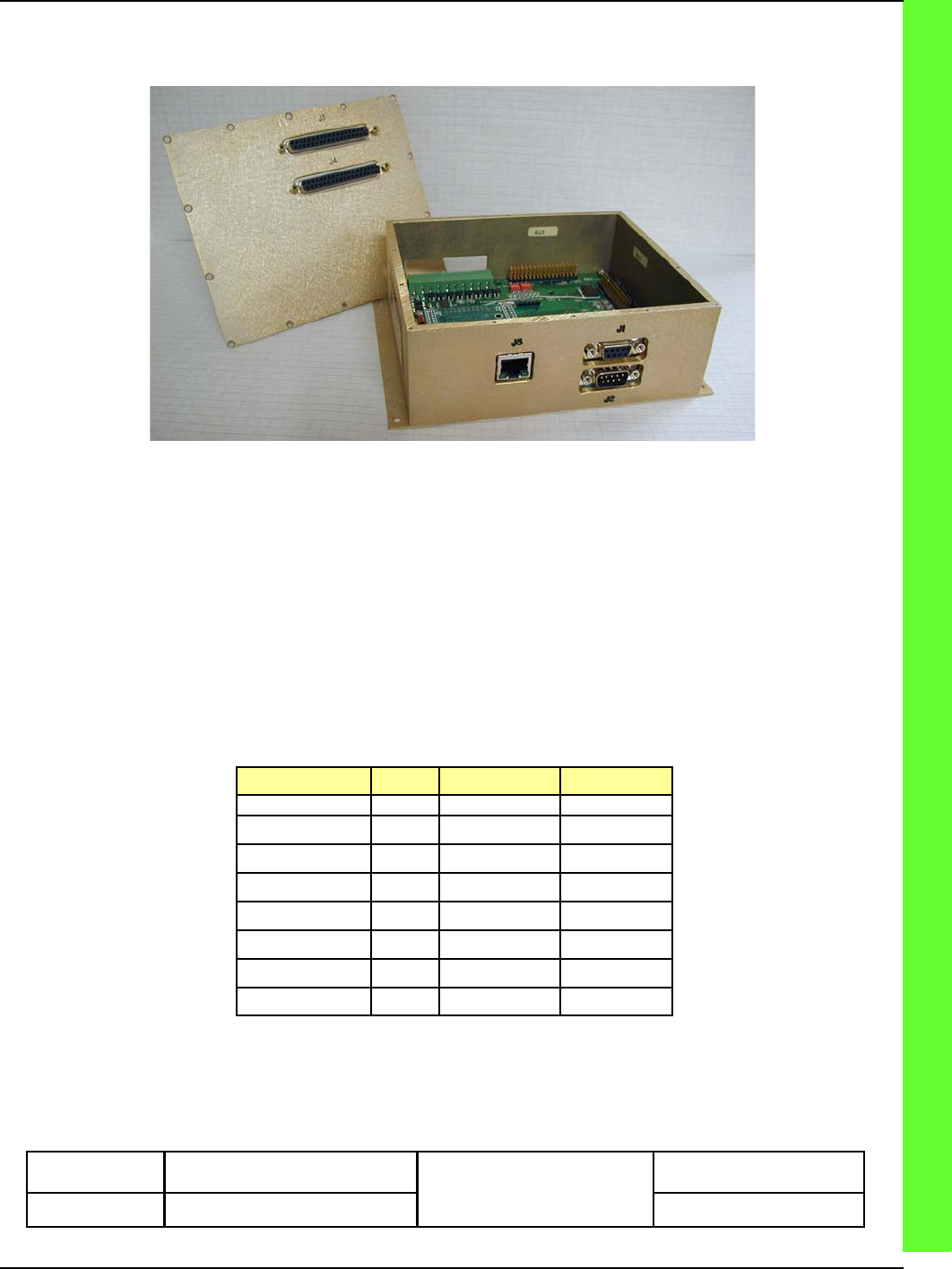
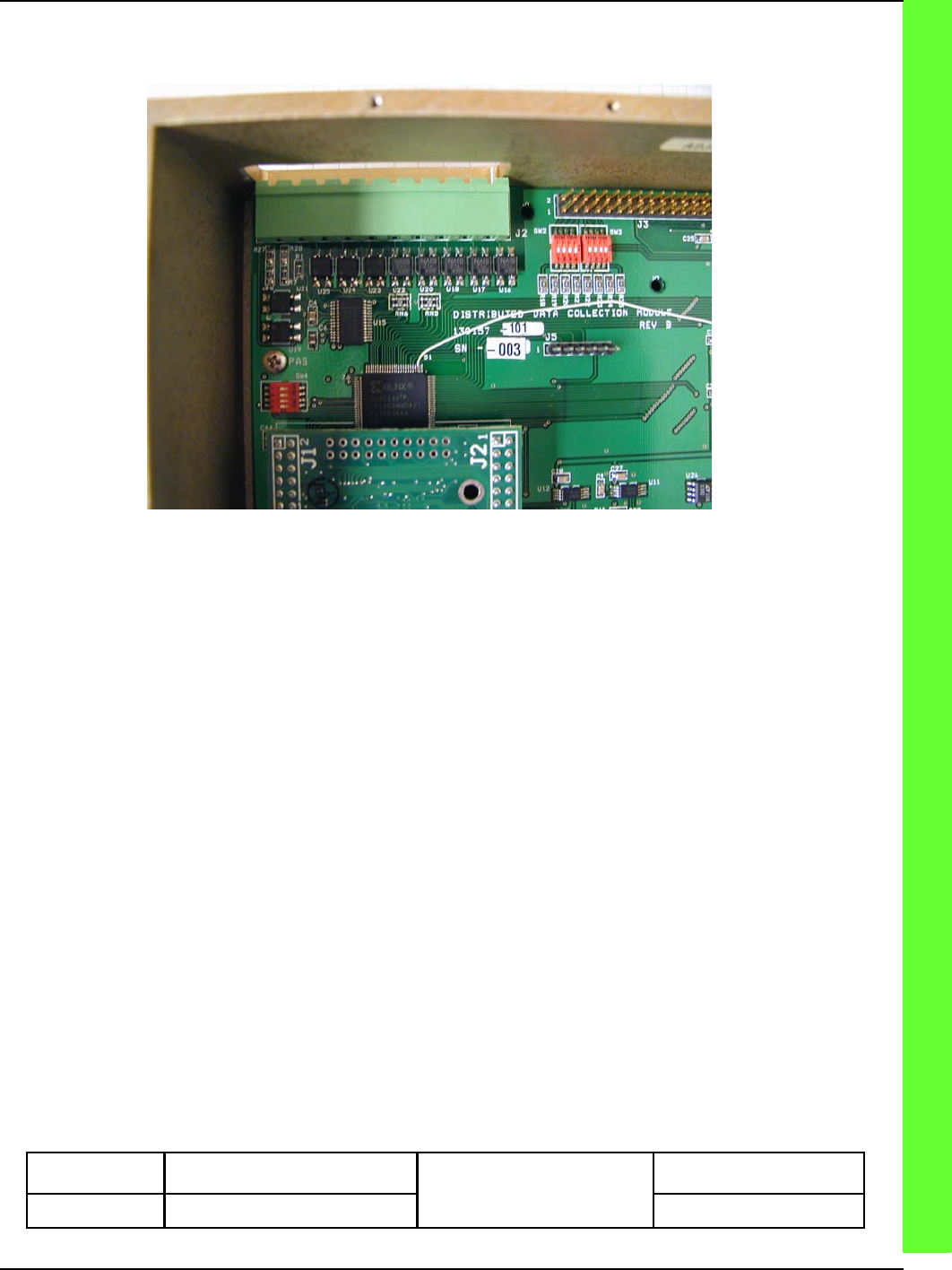
2.4 I/O Ports (J3,J4)
DDC, OPEN
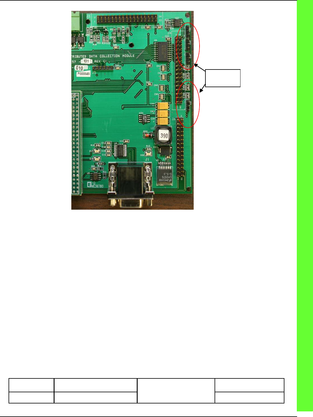
The sixteen wide range discrete DDC inputs are connected to the 37 pin D connector J4 . Each group of
four discrete inputs has an associated pull-up selector, JP1 – JP4. By connecting a jumper between pins
1 & 2 a pull-up will be supplied via 4.7K Ohm resistor to +5VDC. Connecting a jumper between pins 2
& 3 will supply a +24 VDC pull-up voltage via the same 4.7K Ohm resistor. Each discrete input is buff-
ered by a 4.7K Ohm resistor and then a Zener diode regulated to 5.1 volts. A .1 mF capacitor is used as
a filter on each discrete input. Any one of the 16 discrete inputs can recognize a 1.7 to 30 volt signal
without damage to circuits.
JP1 – JP4 Pins J4 Pin Pullup
JP1 1&2 8,9,27,28 +5V
JP1 2&3 +24VDC
JP2 1&2 11,12,29,30 +5V
JP2 2&3 +24VDC
JP3 1&2 13,14,32,33 +5V
JP3 2&3 +24VDC
JP4 1&2 16,17,35,36 +5V
JP4 2&3 +24VDC
Table 5 – JP1-JP4 Pinout
CHAPTER 8 INTERFACE CONTROL DOCUMENTS (ICD)
APPENDIX A INTERFACE CONTROL DOCUMENTS (ICD)
ISSUE/REVISION DATE: 25 JULY 2007 TECHNICAL MANUAL
ISO 9001:2000 PROPRIETARY
Interface Control Document (ICD) ENTERPRISE ELECTRONICS CORPORATION
Rev No. 5 Page 8 of 21
Issue Date 25 July 2007 UM-130365
Distribution Data Collection
Module (DDC)
THE DATA PRESENTED HEREIN REPRESENTS THE INTELLECTUAL PROPERTY OF ENTERPRISE ELECTRONICS CORPORATION (EEC). THIS DATA MAY NOT BE DISTRIBUTED OR REPRODUCED BY
ANY MEANS WITHOUT THE EXPRESS, WRITTEN CONSENT OF EEC.
JP1-JP4
JP1-JP4 LOCATION
The eight buffered TTL outputs are connected to the 37 pin D connector, J4, visible in Figure 4.
The eight analog to digital inputs (ADC) with a resolution of 10 bits are connected to the 37 pin D con-
nector J3, visible in Figure 3. Each input is filtered by a .1 mF capacitor. The reference voltage for the
ADC is 5.0 volts. Input range is from 0 to +5 VDC.
The eight Sink Driver outputs are connected to the 37 pin D connector, J3, visible in Figure 3. Each sink
driver can sink up to 500ma at up to +24VDC. Each sink driver is equipped with a current protection
diode for driving relays or inductive loads.
The DDC auto-ranging DC voltmeter circuit is seen in Figure 5. The auto-ranging DC voltmeter circuit
allows the DDC to be connected to a wide range of bi-polar inputs. Voltage inputs can be bi-polar from
0 to 200 volts. The input impedance is 1 Meg Ohm. There are 8 inputs and 2 grounds. Access to the
voltmeter inputs are through the J2 10-circuit screw down terminal block connector.
CHAPTER 8 INTERFACE CONTROL DOCUMENTS (ICD)
APPENDIX A INTERFACE CONTROL DOCUMENTS (ICD)
ISSUE/REVISION DATE: 25 JULY 2007 TECHNICAL MANUAL
ISO 9001:2000 PROPRIETARY
Interface Control Document (ICD) ENTERPRISE ELECTRONICS CORPORATION
Rev No. 5 Page 9 of 21
Issue Date 25 July 2007 UM-130365
Distribution Data Collection
Module (DDC)
THE DATA PRESENTED HEREIN REPRESENTS THE INTELLECTUAL PROPERTY OF ENTERPRISE ELECTRONICS CORPORATION (EEC). THIS DATA MAY NOT BE DISTRIBUTED OR REPRODUCED BY
ANY MEANS WITHOUT THE EXPRESS, WRITTEN CONSENT OF EEC.
AUTO-RANGING DC VOLTMETER
The DDC module incorporates a digital trigger protection circuit that allows for the input of two sepa-
rate triggers. Trigger inputs are on 37 pin D connector J3 pins 10 and 11. Each trigger input is 50 Ohm
terminated and can take trigger pulses up to 25 V peak with duty up to 50% without damage to circuits.
PRF maximums are set in memory and can be changed at any time using the Ethernet or serial interface.
The DDC provides trigger generation circuitry for local mode testing of the transmitter. The internal/
external trigger mode is selectable via the Ethernet or serial interface and generates 1007 PRF and 250
PRF.
Trigger outputs are on the same 37pin D connector J3 pins 23 and 33.

CHAPTER 8 INTERFACE CONTROL DOCUMENTS (ICD)
APPENDIX A INTERFACE CONTROL DOCUMENTS (ICD)
ISSUE/REVISION DATE: 25 JULY 2007 TECHNICAL MANUAL
ISO 9001:2000 PROPRIETARY
Interface Control Document (ICD) ENTERPRISE ELECTRONICS CORPORATION
Rev No. 5 Page 10 of 21
Issue Date 25 July 2007 UM-130365
Distribution Data Collection
Module (DDC)
THE DATA PRESENTED HEREIN REPRESENTS THE INTELLECTUAL PROPERTY OF ENTERPRISE ELECTRONICS CORPORATION (EEC). THIS DATA MAY NOT BE DISTRIBUTED OR REPRODUCED BY
ANY MEANS WITHOUT THE EXPRESS, WRITTEN CONSENT OF EEC.
I/O Connector J3
Pin Input/
Output Capability
1 AN3 10bit ADC input 0-5VDC
2 AN2 10bit ADC input 0-5VDC
3 AN0 10bit ADC input 0-5VDC
4 AN52 10bit ADC input 0-5VDC
5 Gnd
6 Gnd
7 Gnd
8 Gnd
9 +5VDC VCC
10 TrigIn1 0-30V Pulsed Input
11 TrigIn2 0-30V Pulsed Input
12 TrigOut1 15V or 5V Drive output
13 K8 Relay drive @500ma
14 K6 Relay drive @500ma
15 K4 Relay drive @500ma
16 K2 Relay drive @500ma
17 TrigOut2 5V Drive output
18 NC
19 NC
20 AN1 10bit ADC input 0-5VDC
21 AN56 10bit ADC input 0-5VDC
22 AN53 10bit ADC input 0-5VDC
23 AN55 10bit ADC input 0-5VDC
24 Gnd
25 Gnd
26 Gnd
27 Gnd
28 +5VDC VCC
29 Gnd
30 Gnd
31 Gnd
32 K7 Relay drive @500ma
33 K5 Relay drive @500ma
34 K3 Relay drive @500ma
35 K1 Relay drive @500ma
36 Gnd
37 NC
2.4.1 I/O Pinouts on J3
Table 6 – J3

CHAPTER 8 INTERFACE CONTROL DOCUMENTS (ICD)
APPENDIX A INTERFACE CONTROL DOCUMENTS (ICD)
ISSUE/REVISION DATE: 25 JULY 2007 TECHNICAL MANUAL
ISO 9001:2000 PROPRIETARY
Interface Control Document (ICD) ENTERPRISE ELECTRONICS CORPORATION
Rev No. 5 Page 11 of 21
Issue Date 25 July 2007 UM-130365
Distribution Data Collection
Module (DDC)
THE DATA PRESENTED HEREIN REPRESENTS THE INTELLECTUAL PROPERTY OF ENTERPRISE ELECTRONICS CORPORATION (EEC). THIS DATA MAY NOT BE DISTRIBUTED OR REPRODUCED BY
ANY MEANS WITHOUT THE EXPRESS, WRITTEN CONSENT OF EEC.
2.4.2 I/O Pinouts on J4
I/O Connector J4
Pin Function Capability
1 +24 Source 1 +24VDC Switched @500ma
2 K9 Relay drive @500ma
3 Dout1 TTL output @40ma
4 Dout3 TTL output @40ma
5 Gnd
6 Dout6 TTL output @40ma
7 Dout8 TTL output @40ma
8 Din1 0-30VDC discrete input
9 Din3 0-30VDC discrete input
10 Gnd
11 Din6 0-30VDC discrete input
12 Din8 0-30VDC discrete input
13 Din9 0-30VDC discrete input
14 Din11 0-30VDC discrete input
15 Gnd
16 Din14 0-30VDC discrete input
17 Din16 0-30VDC discrete input
18 NC
19 NC
20 +24V Source 2 +24VDC Switched @500ma
21 K10 Relay drive @500ma
22 Dout2 TTL output @40ma
23 Dout4 TTL output @40ma
24 Dout5 TTL output @40ma
25 Dout7 TTL output @40ma
26 Gnd
27 Din2 0-30VDC discrete input
28 Din4 0-30VDC discrete input
29 Din5 0-30VDC discrete input
30 Din7 0-30VDC discrete input
31 Gnd
32 Din10 0-30VDC discrete input
33 Din12 0-30VDC discrete input
34 Din13 0-30VDC discrete input
35 Din15 0-30VDC discrete input
36 Gnd
37 NC
Table 7 – J4

CHAPTER 8 INTERFACE CONTROL DOCUMENTS (ICD)
APPENDIX A INTERFACE CONTROL DOCUMENTS (ICD)
ISSUE/REVISION DATE: 25 JULY 2007 TECHNICAL MANUAL
ISO 9001:2000 PROPRIETARY
Interface Control Document (ICD) ENTERPRISE ELECTRONICS CORPORATION
Rev No. 5 Page 12 of 21
Issue Date 25 July 2007 UM-130365
Distribution Data Collection
Module (DDC)
THE DATA PRESENTED HEREIN REPRESENTS THE INTELLECTUAL PROPERTY OF ENTERPRISE ELECTRONICS CORPORATION (EEC). THIS DATA MAY NOT BE DISTRIBUTED OR REPRODUCED BY
ANY MEANS WITHOUT THE EXPRESS, WRITTEN CONSENT OF EEC.
2.5 Ethernet (J5)
The Ethernet jack (J5) is located in the rear face of the DDC. This is a standard 10/100-Base-T Ethernet
connection jack.
3.0 Software Interface
There are three communication interfaces that software can use to communicate with the DDC. Serial
and Ethernet interfaces use identical formats for command and control functions in the DDC.
3.1 Serial Control
RS232 serial control is through the console port, Port 0. This port initializes at a baud rate of 115,200
and uses standard 8-N-1 protocol. See section RS232 Pinouts on J1 for more information on the hard-
ware interface.
3.2 Ethernet Control
The DDC has a 10/100 Ethernet interface which can be used for high-speed communications via socket
communications in software.
3.3 Updating the on-board Software
3.3.1 Monitor Program
The DDC has an onboard Monitor program. The monitor program loading is detailed in Appendix A.
3.3.2 Main DDC Program
The main DDC program is flash loaded. To update the program, see Appendix A.
CHAPTER 8 INTERFACE CONTROL DOCUMENTS (ICD)
APPENDIX A INTERFACE CONTROL DOCUMENTS (ICD)
ISSUE/REVISION DATE: 25 JULY 2007 TECHNICAL MANUAL
ISO 9001:2000 PROPRIETARY
Interface Control Document (ICD) ENTERPRISE ELECTRONICS CORPORATION
Rev No. 5 Page 13 of 21
Issue Date 25 July 2007 UM-130365
Distribution Data Collection
Module (DDC)
THE DATA PRESENTED HEREIN REPRESENTS THE INTELLECTUAL PROPERTY OF ENTERPRISE ELECTRONICS CORPORATION (EEC). THIS DATA MAY NOT BE DISTRIBUTED OR REPRODUCED BY
ANY MEANS WITHOUT THE EXPRESS, WRITTEN CONSENT OF EEC.
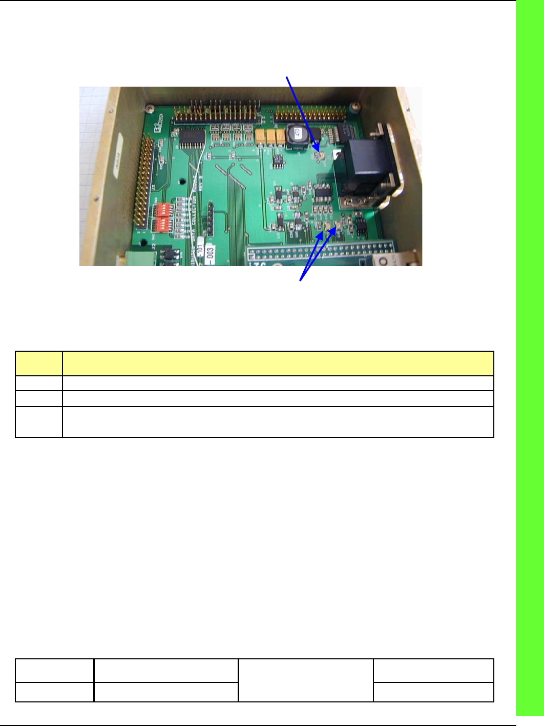
4.0 Troubleshooting the DDC
4.1 LED indicators
LED1
&
2
RS232
The DDC module has three LEDs that are used for the following indications:
Indica-
tor Function
LED 1 Processor running. This LED should blink regularly.
LED 2 Communications link established. This LED should blink regularly.
RS232 RS232 receive level present. This LED should be lit when a good RS232 receive level is detected on
any of the three RS232 ports.
CHAPTER 8 INTERFACE CONTROL DOCUMENTS (ICD)
APPENDIX A INTERFACE CONTROL DOCUMENTS (ICD)
ISSUE/REVISION DATE: 25 JULY 2007 TECHNICAL MANUAL
ISO 9001:2000 PROPRIETARY
Interface Control Document (ICD) ENTERPRISE ELECTRONICS CORPORATION
Rev No. 5 Page 14 of 21
Issue Date 25 July 2007 UM-130365
Distribution Data Collection
Module (DDC)
THE DATA PRESENTED HEREIN REPRESENTS THE INTELLECTUAL PROPERTY OF ENTERPRISE ELECTRONICS CORPORATION (EEC). THIS DATA MAY NOT BE DISTRIBUTED OR REPRODUCED BY
ANY MEANS WITHOUT THE EXPRESS, WRITTEN CONSENT OF EEC.
Appendix A – Software Loading
Introduction
The DRCP firmware and boot configuration data is stored in an on-board flash memory. This document
is to be used as a guide for configuration and downloading of the application firmware. A processor will
need its configuration, modified when it is a new board without an application and initial configuration
or when a configuration item such as the network configuration needs to be changed. Configuration and
application firmware loading is preformed in the boot monitor console.
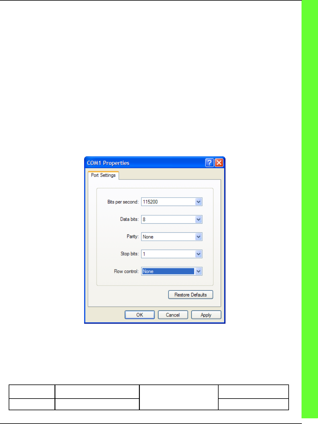
Terminal Setup
The firmware and boot configuration data is accessible via the RS-232 console port of each device and
can easily be accessed at boot time with a PC serial communications program such as Minicom on Linux
or HyperTerminal on Windows.
In our examples we will be using HyperTerminal but these procedures should be preformed easily us-
ing any terminal communications software. The illustration below shows how the communication port
should be configured.
SERIAL PORT CONFIGURATION
CHAPTER 8 INTERFACE CONTROL DOCUMENTS (ICD)
APPENDIX A INTERFACE CONTROL DOCUMENTS (ICD)
ISSUE/REVISION DATE: 25 JULY 2007 TECHNICAL MANUAL
ISO 9001:2000 PROPRIETARY
Interface Control Document (ICD) ENTERPRISE ELECTRONICS CORPORATION
Rev No. 5 Page 15 of 21
Issue Date 25 July 2007 UM-130365
Distribution Data Collection
Module (DDC)
THE DATA PRESENTED HEREIN REPRESENTS THE INTELLECTUAL PROPERTY OF ENTERPRISE ELECTRONICS CORPORATION (EEC). THIS DATA MAY NOT BE DISTRIBUTED OR REPRODUCED BY
ANY MEANS WITHOUT THE EXPRESS, WRITTEN CONSENT OF EEC.
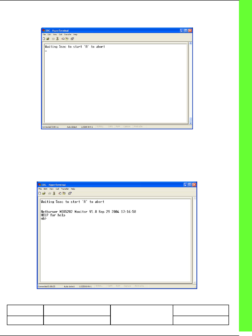
Interrupting the boot process
Once we a have a DRCP module connected to a PC and the terminal software configured properly we
should be able to apply power to the module. When the module begins its boot process it outputs a wait-
ing to start message as displayed below .
WAITING TO START
When the waiting to start message appears the A character must be sent to the device to interrupt the
boot process and enter the configuration screen. Once the boot process has been successfully interrupted,
a command prompt will be displayed as shown below. At this point you are ready to change configura-
tion data or download a new application to the module.
MONITOR PROMPT
CHAPTER 8 INTERFACE CONTROL DOCUMENTS (ICD)
APPENDIX A INTERFACE CONTROL DOCUMENTS (ICD)
ISSUE/REVISION DATE: 25 JULY 2007 TECHNICAL MANUAL
ISO 9001:2000 PROPRIETARY
Interface Control Document (ICD) ENTERPRISE ELECTRONICS CORPORATION
Rev No. 5 Page 16 of 21
Issue Date 25 July 2007 UM-130365
Distribution Data Collection
Module (DDC)
THE DATA PRESENTED HEREIN REPRESENTS THE INTELLECTUAL PROPERTY OF ENTERPRISE ELECTRONICS CORPORATION (EEC). THIS DATA MAY NOT BE DISTRIBUTED OR REPRODUCED BY
ANY MEANS WITHOUT THE EXPRESS, WRITTEN CONSENT OF EEC.
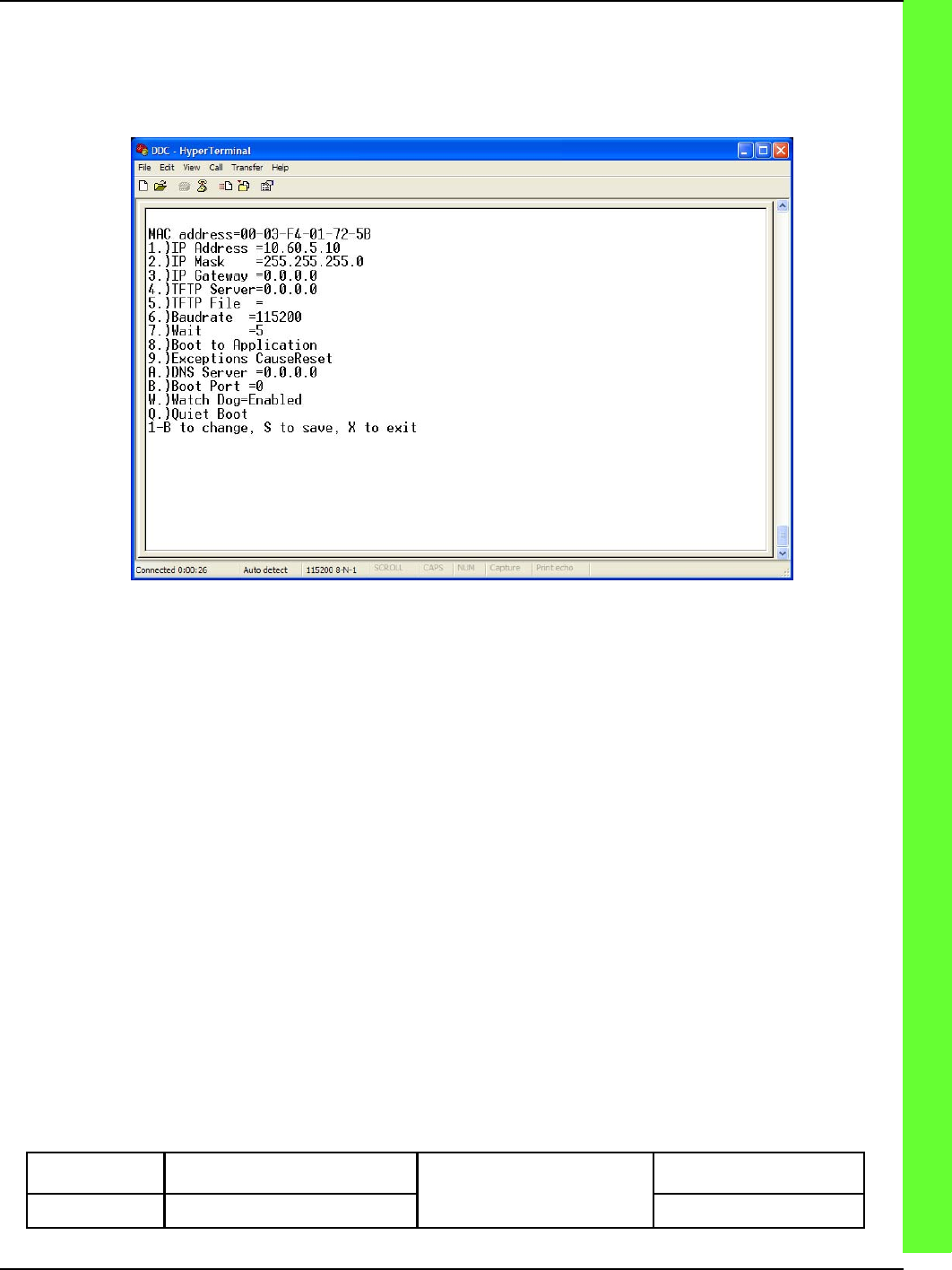
Operational Parameter Configuration
At the command prompt you may enter the setup menu by typing the command setup. The displayed
setup menu should look similar to what is displayed below.
SETUP MENU
The menu is operated by simply entering the number or letter preceding the desired menu option. Once
all desired changes are made simply entering an S will save the options to flash and reboot the processor.
Network Configuration
1) IP ADDRESS
When prompted enter the IP address in the standard IPv4 dotted decimal notation ex: 10.60.5.10.
2) IP MASK
When prompted enter the netmask in the standard IPv4 dotted decimal notation ex: 255.255.255.0
CHAPTER 8 INTERFACE CONTROL DOCUMENTS (ICD)
APPENDIX A INTERFACE CONTROL DOCUMENTS (ICD)
ISSUE/REVISION DATE: 25 JULY 2007 TECHNICAL MANUAL
ISO 9001:2000 PROPRIETARY
Interface Control Document (ICD) ENTERPRISE ELECTRONICS CORPORATION
Rev No. 5 Page 17 of 21
Issue Date 25 July 2007 UM-130365
Distribution Data Collection
Module (DDC)
THE DATA PRESENTED HEREIN REPRESENTS THE INTELLECTUAL PROPERTY OF ENTERPRISE ELECTRONICS CORPORATION (EEC). THIS DATA MAY NOT BE DISTRIBUTED OR REPRODUCED BY
ANY MEANS WITHOUT THE EXPRESS, WRITTEN CONSENT OF EEC.
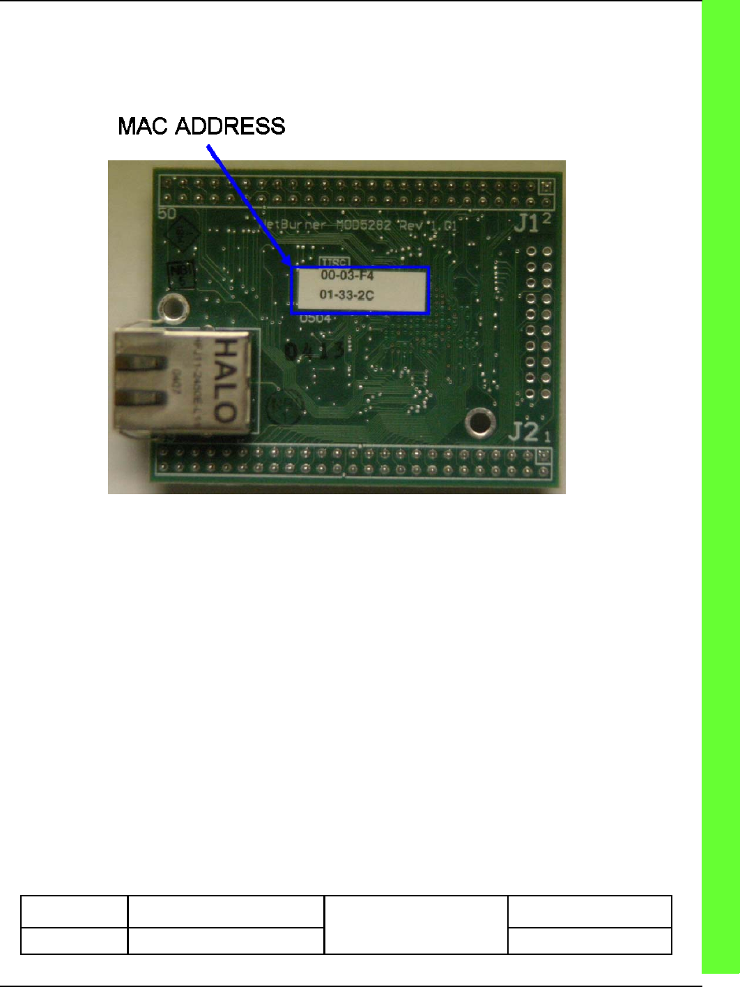
MAC Address
When changing any of the network configuration options you may be asked to enter the 12 digit
Ethernet MAC address of the module if the module does not have a valid MAC address stored in flash.
Each DRCP processor module has a unique MAC address assigned to it. This address can be found on a
label atop the module processor board as illustrated below.
ETHERNET MAC ADDRESS LABEL
In most cases entering of the MAC address will not be required.
Additional Configuration
Besides network configuration it is necessary to configure a few other operating parameters.
Wait
The Wait menu item controls how long the processor waits in seconds before beginning execution of the
application stored in flash.
Boot To
The Boot To menu item controls whether the processor boots to the application software or the monitor
application. This option should be configured to Boot To Application for normal operation.
Exceptions Cause
The Exceptions Cause menu item controls how the monitor firmware will handle exceptions in the appli-
cation firmware. This option should be set to Exceptions CauseReset.
CHAPTER 8 INTERFACE CONTROL DOCUMENTS (ICD)
APPENDIX A INTERFACE CONTROL DOCUMENTS (ICD)
ISSUE/REVISION DATE: 25 JULY 2007 TECHNICAL MANUAL
ISO 9001:2000 PROPRIETARY
Interface Control Document (ICD) ENTERPRISE ELECTRONICS CORPORATION
Rev No. 5 Page 18 of 21
Issue Date 25 July 2007 UM-130365
Distribution Data Collection
Module (DDC)
THE DATA PRESENTED HEREIN REPRESENTS THE INTELLECTUAL PROPERTY OF ENTERPRISE ELECTRONICS CORPORATION (EEC). THIS DATA MAY NOT BE DISTRIBUTED OR REPRODUCED BY
ANY MEANS WITHOUT THE EXPRESS, WRITTEN CONSENT OF EEC.
Watch Dog
The Watch Dog menu item enables or disables the on chip watchdog timer. This item should be enabled
after downloading the application firmware. If this option is enabled and changes need to be made via
the boot monitor console, this item should be changed and saved first. Failure to disable the watchdog
will result in the repeated resetting of the processor while in the boot monitor console.
Quiet/Loud Boot
The Quiet/Loud Boot menu item toggle configures whether the monitor should display the “Waiting to
start message” at boot time. When the menu item reads Quiet Boot the module will display the boot
message and selecting the menu item will toggle it to quite mode. When Loud Boot is displayed, the
boot message will not appear and selecting the menu item will toggle it to loud mode. This option is
used when the NetBurner’s COM0 is used to drive an external device such as a LCD panel and if you do
not wish to see the boot message on the device.
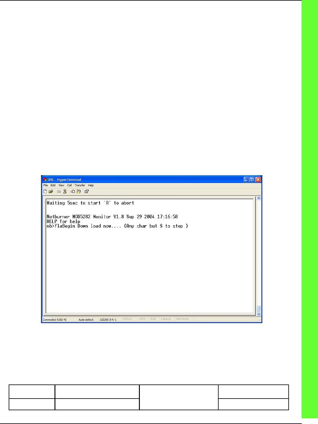
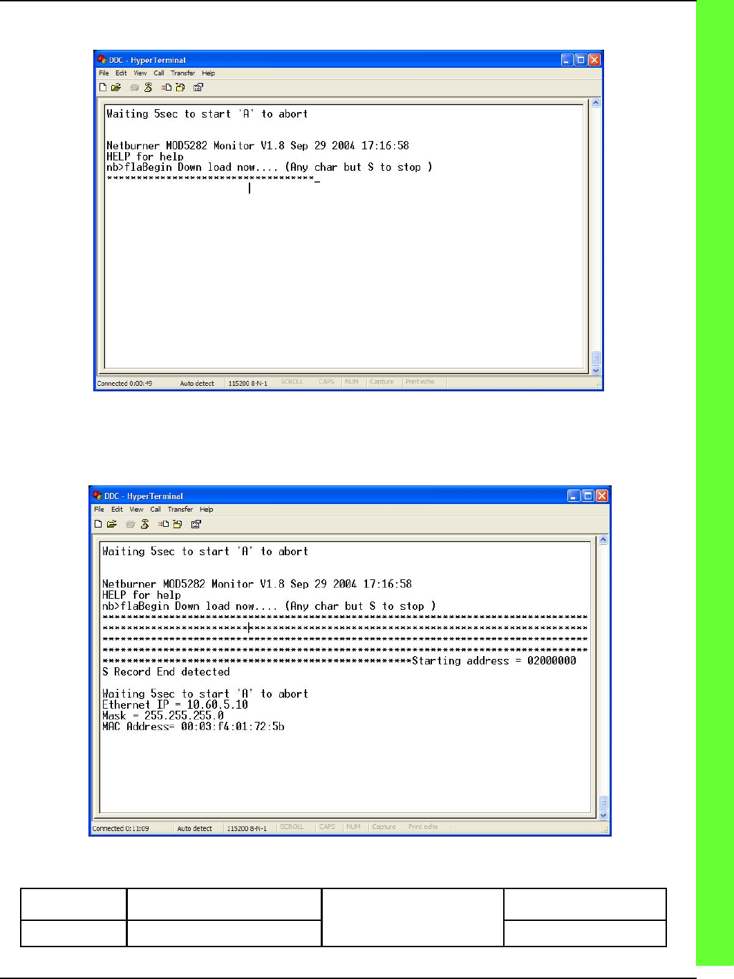
Application Firmware Download
To download the application firmware into flash follow the steps to enter the console monitor prompt
above. Once at the console monitor prompt the application software can be downloaded to the module
using the fla command. This command instructs the module to await transfer of the compressed S record
application image. The module will respond with Begin Down load now… as seen in the figure below.
DOWNLOAD COMMAND
CHAPTER 8 INTERFACE CONTROL DOCUMENTS (ICD)
APPENDIX A INTERFACE CONTROL DOCUMENTS (ICD)
ISSUE/REVISION DATE: 25 JULY 2007 TECHNICAL MANUAL
ISO 9001:2000 PROPRIETARY
Interface Control Document (ICD) ENTERPRISE ELECTRONICS CORPORATION
Rev No. 5 Page 19 of 21
Issue Date 25 July 2007 UM-130365
Distribution Data Collection
Module (DDC)
THE DATA PRESENTED HEREIN REPRESENTS THE INTELLECTUAL PROPERTY OF ENTERPRISE ELECTRONICS CORPORATION (EEC). THIS DATA MAY NOT BE DISTRIBUTED OR REPRODUCED BY
ANY MEANS WITHOUT THE EXPRESS, WRITTEN CONSENT OF EEC.
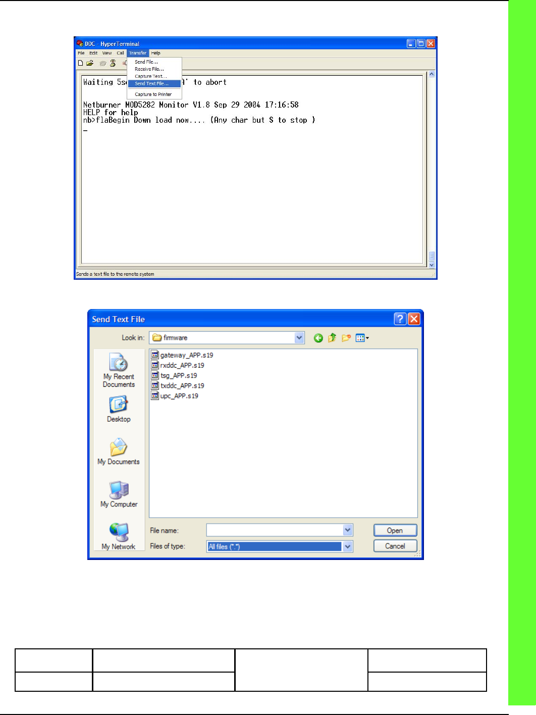
The next step is to transfer the application using your terminal software send text file or ASCII file
transfer function. The next two figures show how this is done in HyperTerminal.
SEND TEXT FILE
SEND TEXT FILE
CHAPTER 8 INTERFACE CONTROL DOCUMENTS (ICD)
APPENDIX A INTERFACE CONTROL DOCUMENTS (ICD)
ISSUE/REVISION DATE: 25 JULY 2007 TECHNICAL MANUAL
ISO 9001:2000 PROPRIETARY
Interface Control Document (ICD) ENTERPRISE ELECTRONICS CORPORATION
Rev No. 5 Page 20 of 21
Issue Date 25 July 2007 UM-130365
Distribution Data Collection
Module (DDC)
THE DATA PRESENTED HEREIN REPRESENTS THE INTELLECTUAL PROPERTY OF ENTERPRISE ELECTRONICS CORPORATION (EEC). THIS DATA MAY NOT BE DISTRIBUTED OR REPRODUCED BY
ANY MEANS WITHOUT THE EXPRESS, WRITTEN CONSENT OF EEC.
While the file download is in progress the module with display a series of * characters indicating that it
is receiving the application from the host.
TRANSFER IN PROGRESS
Once the download is complete the module will announce that it has detected the end of the S record,
reset itself and run the downloaded application.
DOWNLOAD COMPLETE
CHAPTER 8 INTERFACE CONTROL DOCUMENTS (ICD)
APPENDIX A INTERFACE CONTROL DOCUMENTS (ICD)
ISSUE/REVISION DATE: 25 JULY 2007 TECHNICAL MANUAL
ISO 9001:2000 PROPRIETARY
Interface Control Document (ICD) ENTERPRISE ELECTRONICS CORPORATION
Rev No. 5 Page 21 of 21
Issue Date 25 July 2007 UM-130365
Distribution Data Collection
Module (DDC)
THE DATA PRESENTED HEREIN REPRESENTS THE INTELLECTUAL PROPERTY OF ENTERPRISE ELECTRONICS CORPORATION (EEC). THIS DATA MAY NOT BE DISTRIBUTED OR REPRODUCED BY
ANY MEANS WITHOUT THE EXPRESS, WRITTEN CONSENT OF EEC.
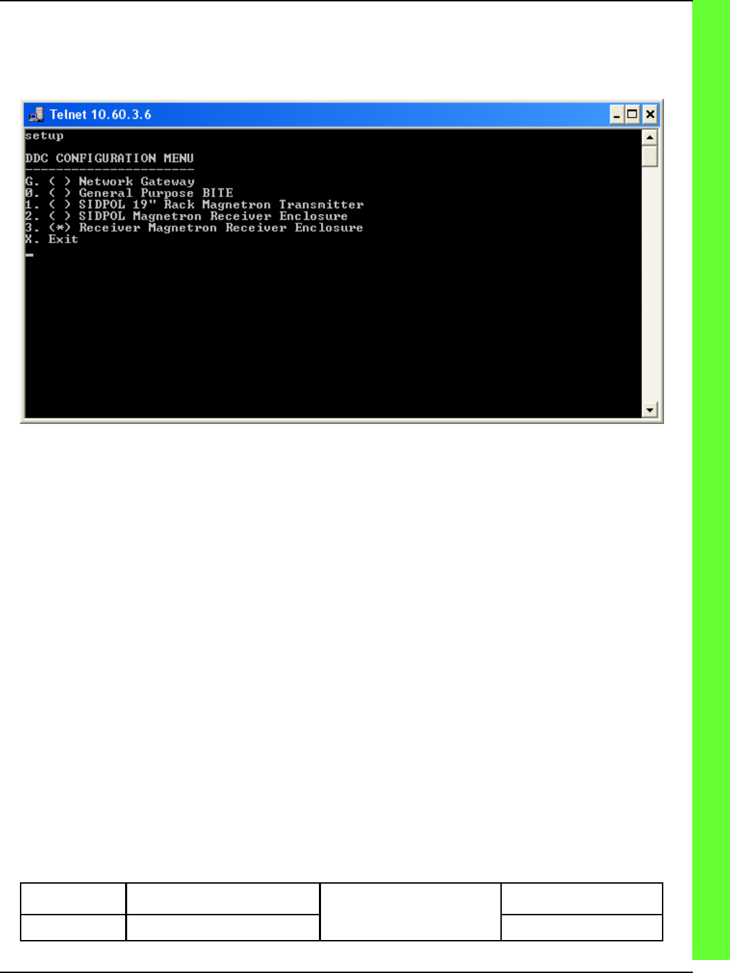
Personality Configuration
Once the DDC software has been downloaded to the device it is necessary to configure the DDC’s per-
sonality by running the setup command from the DDC’s command line interface on COM0 or via telnet.
SETUP
After selecting the correct configuration options for your module it is necessary to reset the module by
issuing the reset command. The DDC will now reboot and run you selected configuration.